Embed Size (px)
Citation preview
KISSsoft 03/2016 – Instruction 102
Consideration of the deformation of a planet carrier
Step by step instructions
KISSsoft AG
Rosengartenstrasse 4
8608 Bubikon
Switzerland
Tel: +41 55 254 20 50
Fax: +41 55 254 20 51
www.KISSsoft.AG

10.03.2016 2 / 17
Contents
1 Introduction .............................................................................................................................................. 3 2 Step by step instructions .......................................................................................................................... 3 3 General comments ................................................................................................................................. 12 Annex 1. Comparison between the deformations of a single-sided and double-sided planet carrier ........... 13
10.03.2016 3 / 17
1 Introduction
Since KISSsoft 2015 version, the misalignment of a planet pin in the planet carrier due to the deformations of
the carrier can be input in many different ways, including its calculation in the background with an FEM tool.
This instruction document explains step by step, how the whole process can be completed.
2 Step by step instructions
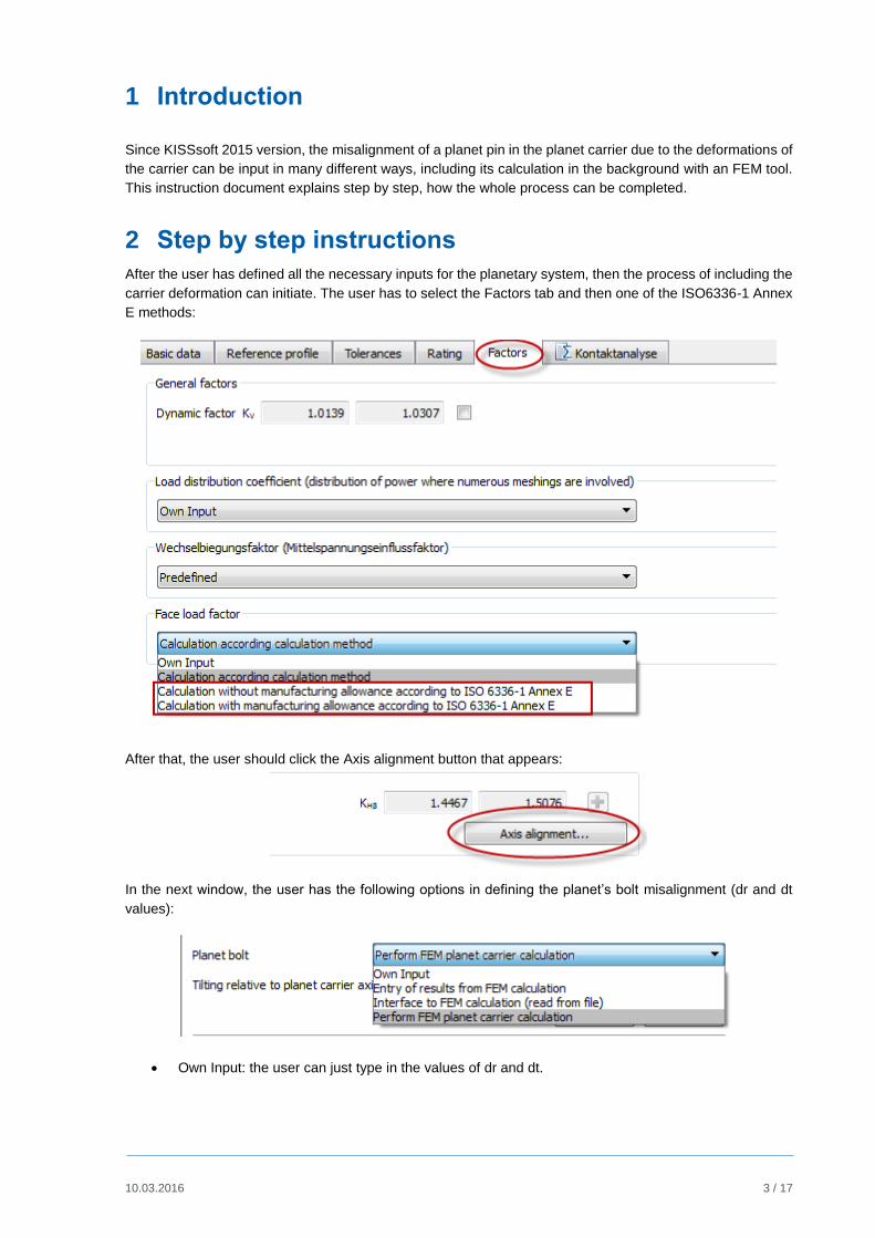
After the user has defined all the necessary inputs for the planetary system, then the process of including the
carrier deformation can initiate. The user has to select the Factors tab and then one of the ISO6336-1 Annex
E methods:
After that, the user should click the Axis alignment button that appears:
In the next window, the user has the following options in defining the planet’s bolt misalignment (dr and dt
values):
Own Input: the user can just type in the values of dr and dt.
10.03.2016 4 / 17
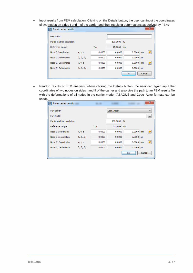
Input results from FEM calculation. Clicking on the Details button, the user can input the coordinates
of two nodes on sides I and II of the carrier and their resulting deformations as derived by FEM:
Read in results of FEM analysis, where clicking the Details button, the user can again input the
coordinates of two nodes on sides I and II of the carrier and also give the path to an FEM results file
with the deformations of all nodes in the carrier model (ABAQUS and Code_Aster formats can be
used).
10.03.2016 5 / 17
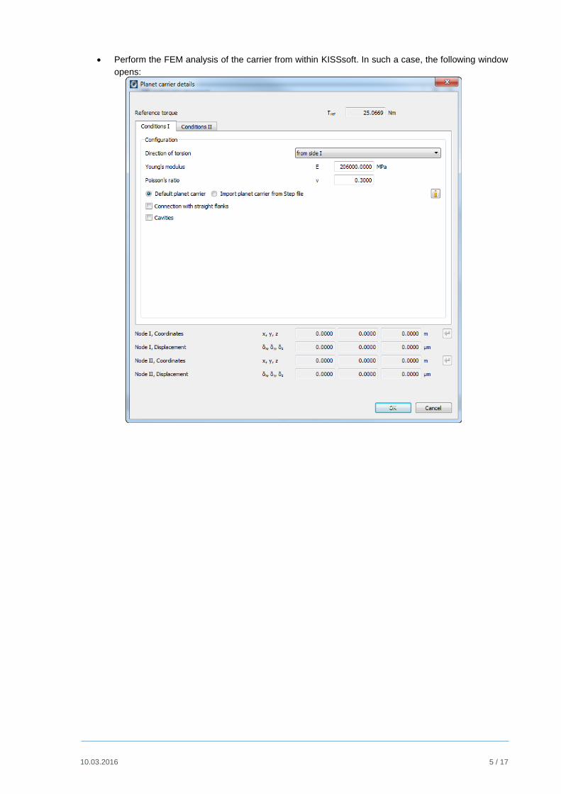
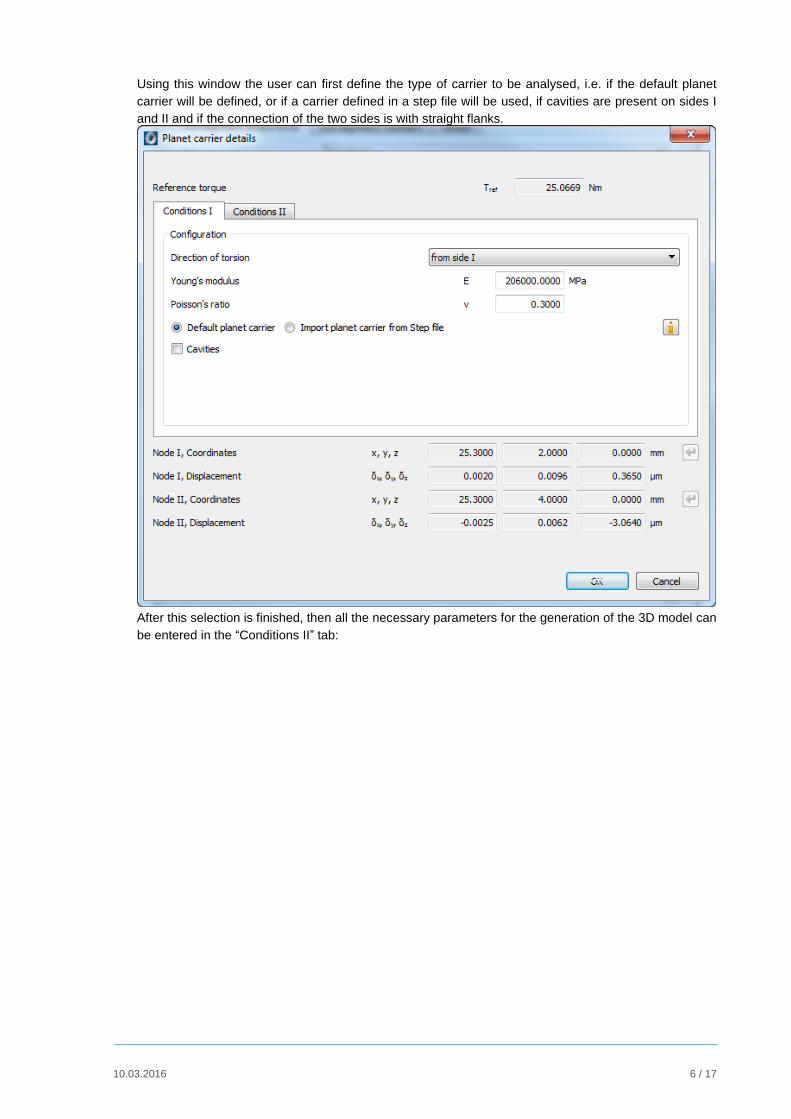
Perform the FEM analysis of the carrier from within KISSsoft. In such a case, the following window
opens:
10.03.2016 6 / 17
Using this window the user can first define the type of carrier to be analysed, i.e. if the default planet
carrier will be defined, or if a carrier defined in a step file will be used, if cavities are present on sides I
and II and if the connection of the two sides is with straight flanks.
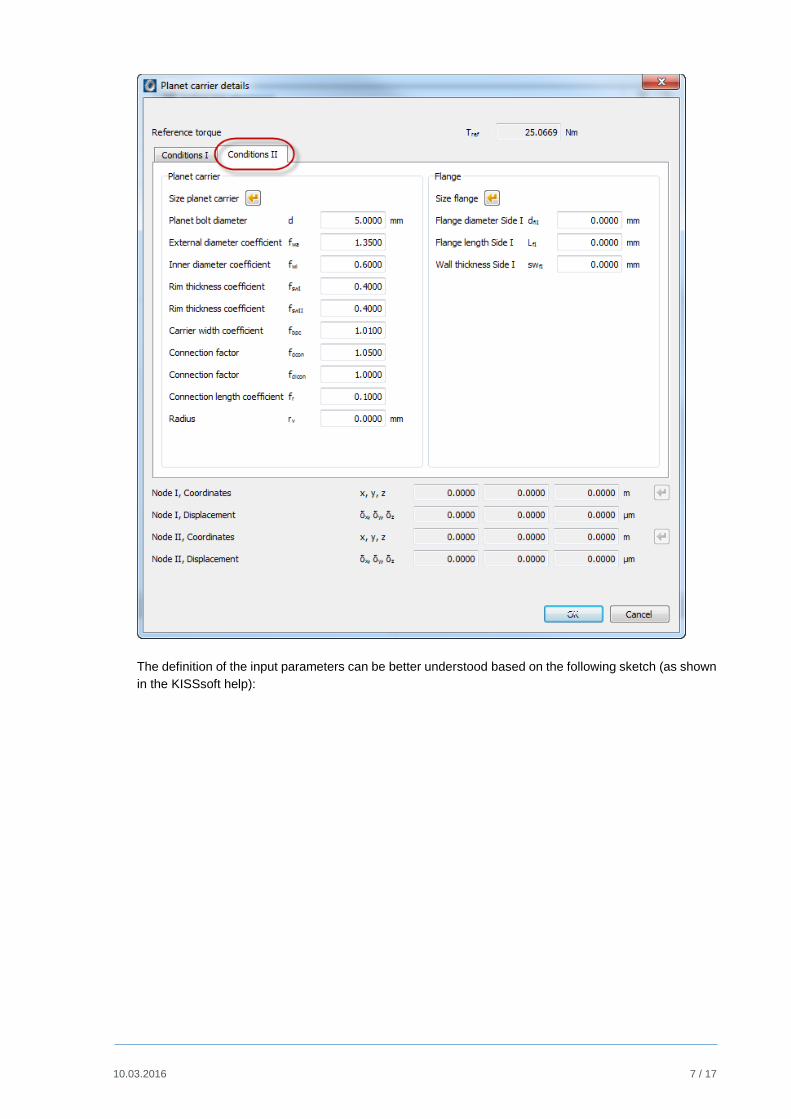
After this selection is finished, then all the necessary parameters for the generation of the 3D model can
be entered in the “Conditions II” tab:
10.03.2016 7 / 17
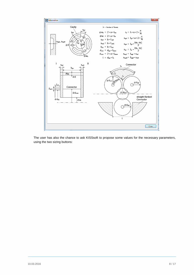
The definition of the input parameters can be better understood based on the following sketch (as shown
in the KISSsoft help):
10.03.2016 8 / 17
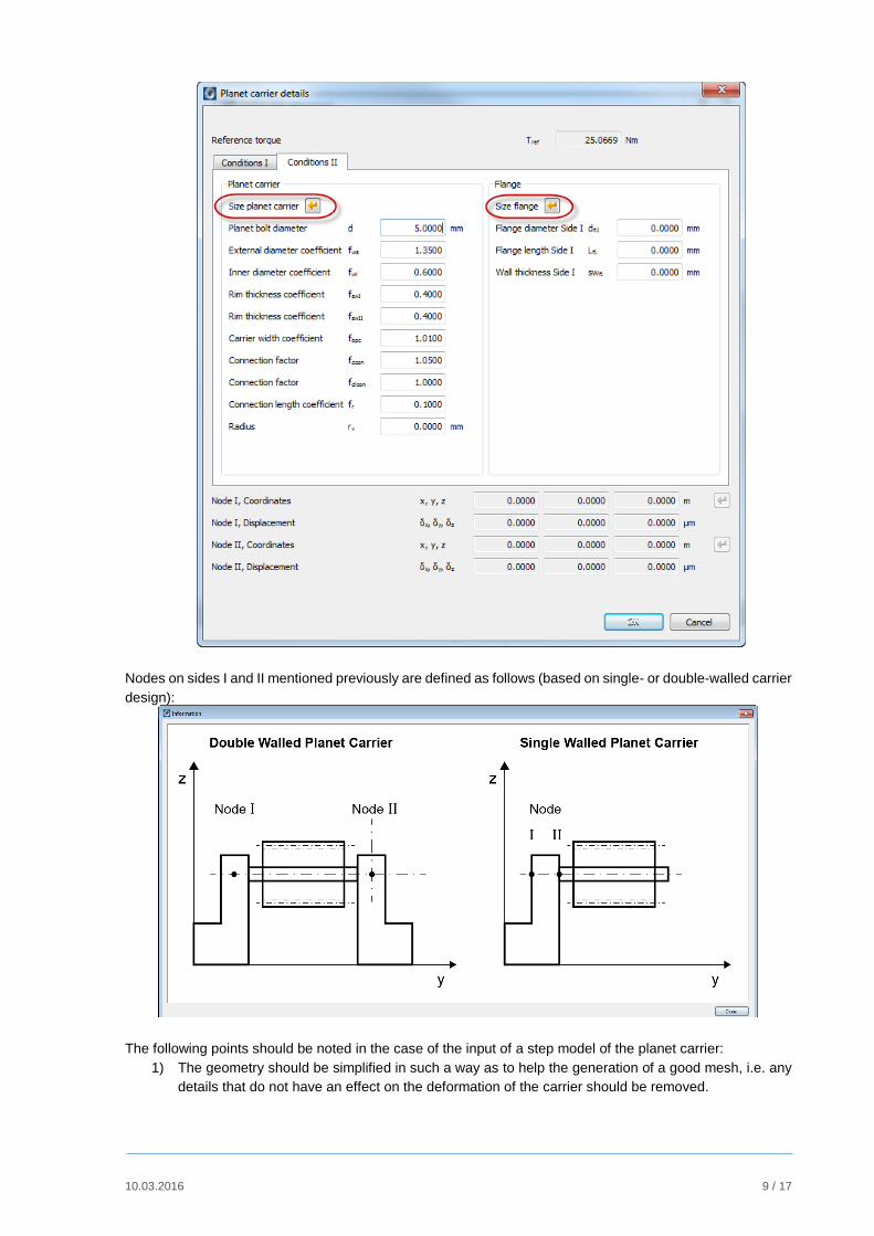
The user has also the chance to ask KISSsoft to propose some values for the necessary parameters,
using the two sizing buttons:
10.03.2016 9 / 17
Nodes on sides I and II mentioned previously are defined as follows (based on single- or double-walled carrier
design):
The following points should be noted in the case of the input of a step model of the planet carrier:
1) The geometry should be simplified in such a way as to help the generation of a good mesh, i.e. any
details that do not have an effect on the deformation of the carrier should be removed.
10.03.2016 10 / 17
2) The planet carrier should not include any planet bolts, since they will be generated automatically.
3) The planet bolt and the flange inner diameters should be given with adequate accuracy, so as to
generate the complete model correctly.
4) The planet carrier is hold in place (clamped) at the cylindrical area defined by the flange diameter
and the start and end clamping positions.
5) The planet bolts are cylinders with the given diameter and length defined by the coordinates of their
start and end positions.
6) It is strictly advised to check the generated mesh inside Salome after the solution, in order to make
sure that it correctly represents the input geometry and boundary conditions.
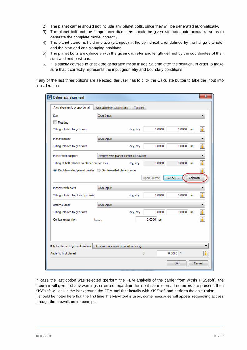
If any of the last three options are selected, the user has to click the Calculate button to take the input into
consideration:
In case the last option was selected (perform the FEM analysis of the carrier from within KISSsoft), the
program will give first any warnings or errors regarding the input parameters. If no errors are present, then
KISSsoft will call in the background the FEM tool that installs with KISSsoft and perform the calculation.
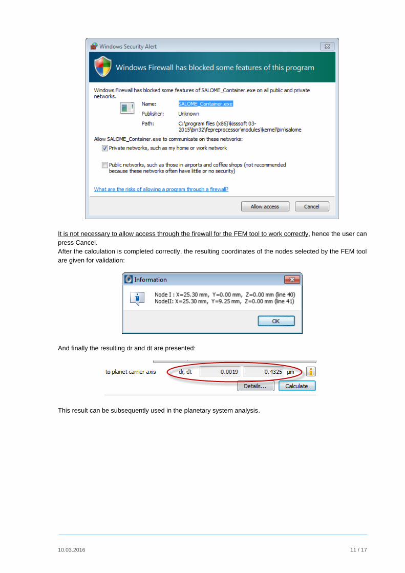
It should be noted here that the first time this FEM tool is used, some messages will appear requesting access
through the firewall, as for example:
10.03.2016 11 / 17
It is not necessary to allow access through the firewall for the FEM tool to work correctly, hence the user can
press Cancel.
After the calculation is completed correctly, the resulting coordinates of the nodes selected by the FEM tool
are given for validation:
And finally the resulting dr and dt are presented:
This result can be subsequently used in the planetary system analysis.
10.03.2016 12 / 17
3 General comments
Further details on the FEM tool used by KISSsoft are given in the KISSsoft manual.
A separate instructions document is available describing the necessary steps to access the 3D
model, the FEM mesh and the FEM results of the planet carrier, as derived in the background by the
FEM tool.
The info buttons in all the above windows can give information on various definitions on the
process, as for example the definition of dr and dt misalignments, or the definition of the parameters
for the 3D model of the planet carrier.
10.03.2016 13 / 17
Annex 1. Comparison between the deformations of a single-sided and double-sided planet carrier
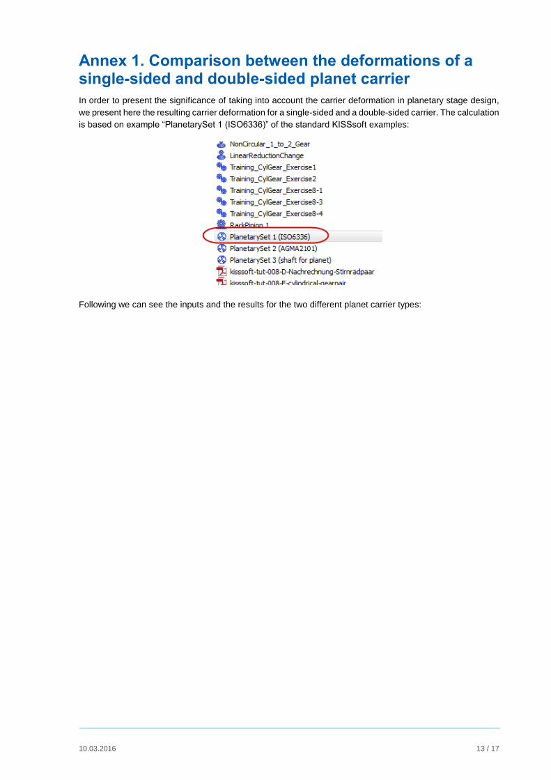
In order to present the significance of taking into account the carrier deformation in planetary stage design,
we present here the resulting carrier deformation for a single-sided and a double-sided carrier. The calculation
is based on example “PlanetarySet 1 (ISO6336)” of the standard KISSsoft examples:
Following we can see the inputs and the results for the two different planet carrier types:
10.03.2016 14 / 17
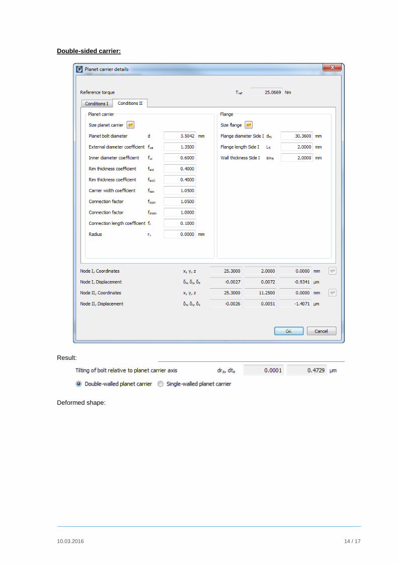
Double-sided carrier:
Result:
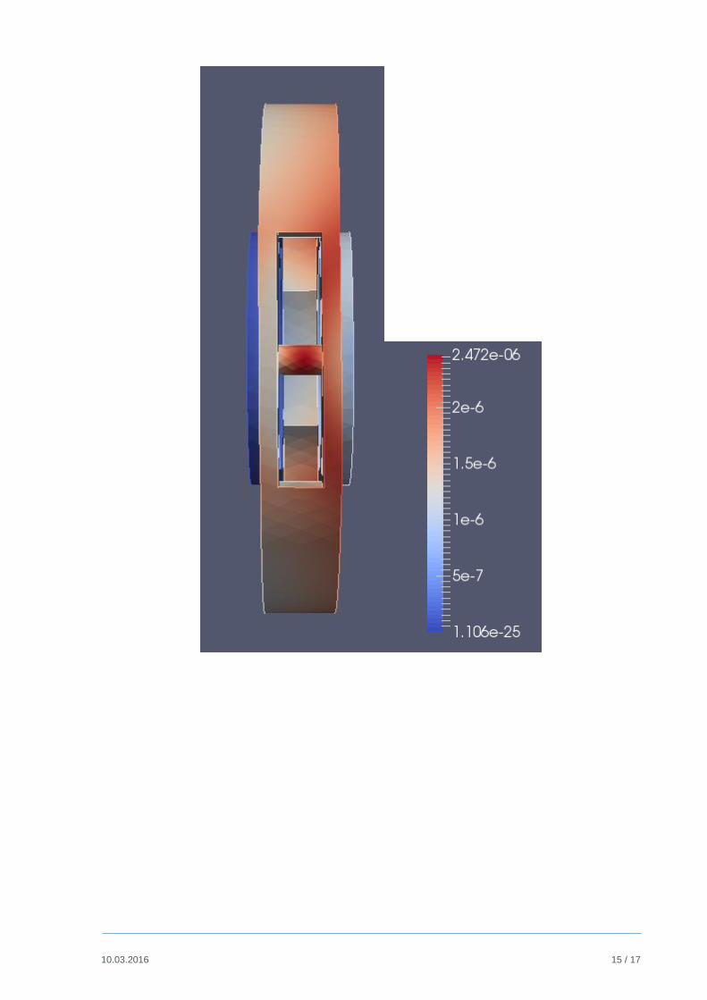
Deformed shape:
10.03.2016 15 / 17
10.03.2016 16 / 17
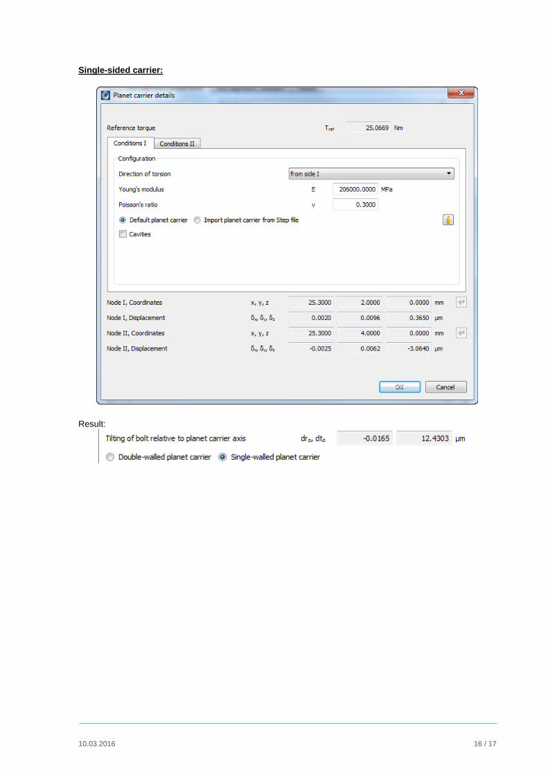
Single-sided carrier:
Result:
10.03.2016 17 / 17
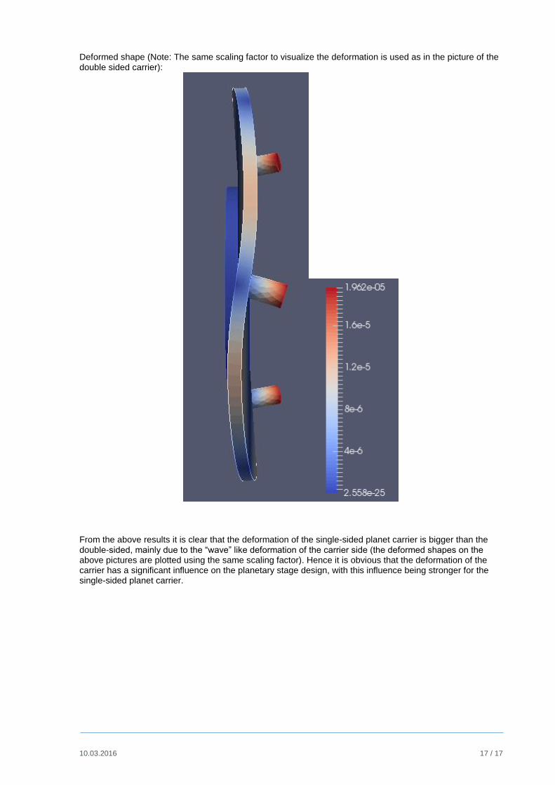
Deformed shape (Note: The same scaling factor to visualize the deformation is used as in the picture of the double sided carrier):
From the above results it is clear that the deformation of the single-sided planet carrier is bigger than the double-sided, mainly due to the “wave” like deformation of the carrier side (the deformed shapes on the above pictures are plotted using the same scaling factor). Hence it is obvious that the deformation of the carrier has a significant influence on the planetary stage design, with this influence being stronger for the single-sided planet carrier.