Embed Size (px)
Citation preview
SymbolsTo allow quick and easy consultation, this manual uses graphic symbols to highlight situations in which maximum care is required, as well as practical advice or information. Pay attention to the meaning of the symbols since they serve to avoid repeating tech-nical concepts or safety warnings throughout the text. The sym-bols should therefore be seen as real reminders. Please refer to this page whenever in doubt as to their meaning.
WarningFailure to follow these instructions might give raise to a dangerous situation and provoke severe personal injuries or even death.
CautionFailure to follow these instructions might cause damages to the vehicle and/or its components.
NotesUseful information on the procedure being described.
ReferencesParts highlighted in grey and with a numeric reference (Example 1 ) are the accessory to be installed and any assembly compo-
nents supplied with the kit.
Parts with an alphabetic reference (Example A ) are the original components fitted on the vehicle.
Any right- or left-hand indication refers to the vehicle direction of travel.
General notes
WarningCarefully perform the operations on the following pages since they might negatively affect rider safety.
WarningCarefully perform the operations on the following pages since they might negatively affect rider safety.
NotesThe following documents are necessary for assembling the Kit: Workshop Manual of your bike model.
NotesShould it be necessary to change any kit parts, please refer to the attached spare part table.
WarningOperating, servicing and maintaining a passenger vehicle or off-highway motor vehicle can expose you to chemicals including en-gine exhaust, carbon monoxide, phthalates, and lead, which are known to the State of California to cause cancer and birth defects or other reproductive harm. To minimize exposure, avoid breath-ing exhaust, do not idle the engine except as necessary, service your vehicle in a well-ventilated area and wear gloves or wash your hands frequently when servicing your vehicle. For more informa-tion go to www.P65Warnings.ca.gov/passenger-vehicle.
Steering damper kit - 96280591AA
SimbologiaPer una lettura rapida e razionale sono stati impiegati simboli che evidenziano situazioni di massima attenzione, consigli pratici o semplici informazioni. Prestare molta attenzione al significato dei simboli, in quanto la loro funzione è quella di non dovere ripete-re concetti tecnici o avvertenze di sicurezza. Sono da considerare, quindi, dei veri e propri “promemoria”. Consultare questa pagina ogni volta che sorgeranno dubbi sul loro significato.
AttenzioneLa non osservanza delle istruzioni riportate può creare una situa-zione di pericolo e causare gravi lesioni personali e anche la morte.
ImportanteIndica la possibilità di arrecare danno al veicolo e/o ai suoi compo-nenti se le istruzioni riportate non vengono eseguite.
NoteFornisce utili informazioni sull’operazione in corso.
RiferimentiI particolari evidenziati in grigio e riferimento numerico (Es. 1 ) rappresentano l’accessorio da installare e gli eventuali componenti di montaggio forniti a kit.
I particolari con riferimento alfabetico (Es. A ) rappresentano i componenti originali presenti sul motoveicolo.
Tutte le indicazioni destro o sinistro si riferiscono al senso di marcia del motociclo.
Avvertenze generali
AttenzioneLe operazioni riportate nelle pagine seguenti devono essere ese-guite da un tecnico specializzato o da un’officina autorizzata Du-cati.
AttenzioneLe operazioni riportate nelle pagine seguenti se non eseguite a re-gola d’arte possono pregiudicare la sicurezza del pilota.
NoteDocumentazione necessaria per eseguire il montaggio del Kit è il Manuale Officina, relativo al modello di moto in vostro possesso.
NoteNel caso fosse necessaria la sostituzione di un componente del kit consultare la tavola ricambi allegata.
Kit ammortizzatore di sterzo - 96280591AA
1
ISTR - 986 / 00
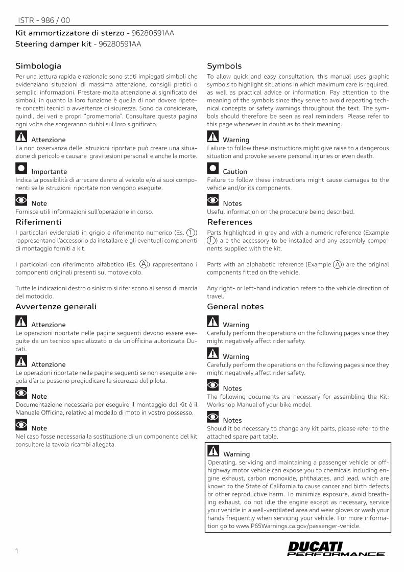
Pos. Denominazione Description
1 Ammortizatore di sterzo Steering damper
2 Morsetto Clamp
3 Staffa centrale Central bracket
4 Staffa laterale Side bracket
5 Vite TCEI M6x45 TCEI screw M6x456 Distanziale Spacer7 Anello OR O-RING8 Distanziale Spacer9 Vite speciale TCCF M6 Special TCCF screw M610 Vite TCEIF M6x30 TCEIF M6x30 screw11 Vite TCEIF M5x14 TCEIF screw M5x1412 Vite STEI M4x6 STEI screw M4x613 Distanziale con collare Spacer with collar14 Rondella Washer15 Vite TBEI M6x25 TBEI screw M6x2516 Vite speciale M6 Special screw M6
2
ISTR 986 / 00
2
1
9
8
7
14
15
16
7
4
10
7
13
11 11
6
7
5
83
10
12
2
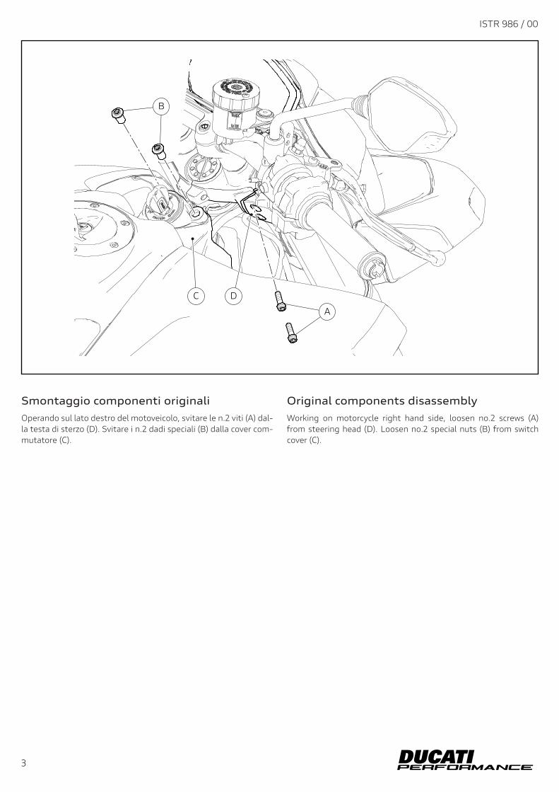
Original components disassemblyWorking on motorcycle right hand side, loosen no.2 screws (A) from steering head (D). Loosen no.2 special nuts (B) from switch cover (C).
Smontaggio componenti originaliOperando sul lato destro del motoveicolo, svitare le n.2 viti (A) dal-la testa di sterzo (D). Svitare i n.2 dadi speciali (B) dalla cover com-mutatore (C).
ISTR 986 / 00
3
A
C D
B
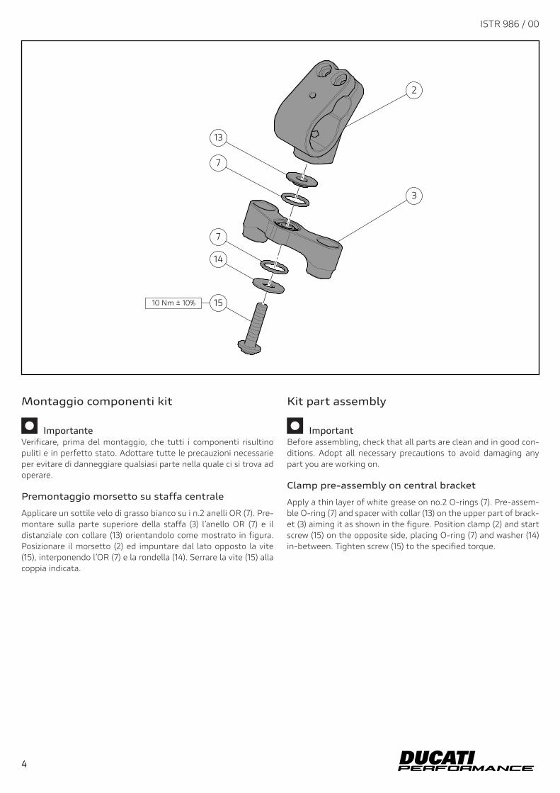
Kit part assembly
ImportantBefore assembling, check that all parts are clean and in good con-ditions. Adopt all necessary precautions to avoid damaging any part you are working on.
Clamp pre-assembly on central bracket
Apply a thin layer of white grease on no.2 O-rings (7). Pre-assem-ble O-ring (7) and spacer with collar (13) on the upper part of brack-et (3) aiming it as shown in the figure. Position clamp (2) and start screw (15) on the opposite side, placing O-ring (7) and washer (14) in-between. Tighten screw (15) to the specified torque.
Montaggio componenti kit
ImportanteVerificare, prima del montaggio, che tutti i componenti risultino puliti e in perfetto stato. Adottare tutte le precauzioni necessarie per evitare di danneggiare qualsiasi parte nella quale ci si trova ad operare.
Premontaggio morsetto su staffa centrale
Applicare un sottile velo di grasso bianco su i n.2 anelli OR (7). Pre-montare sulla parte superiore della staffa (3) l’anello OR (7) e il distanziale con collare (13) orientandolo come mostrato in figura. Posizionare il morsetto (2) ed impuntare dal lato opposto la vite (15), interponendo l’OR (7) e la rondella (14). Serrare la vite (15) alla coppia indicata.
4
ISTR 986 / 00
4
2
13
7
3
7
14
1510 Nm ± 10%
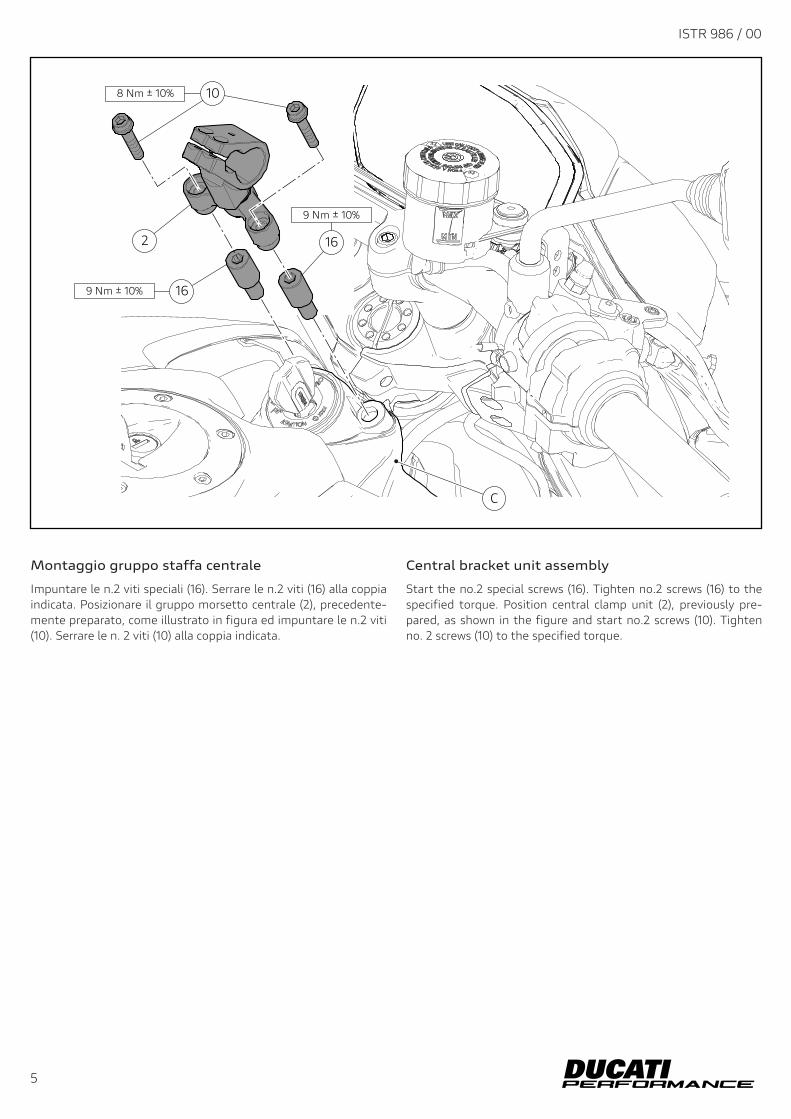
Central bracket unit assembly
Start the no.2 special screws (16). Tighten no.2 screws (16) to the specified torque. Position central clamp unit (2), previously pre-pared, as shown in the figure and start no.2 screws (10). Tighten no. 2 screws (10) to the specified torque.
Montaggio gruppo staffa centrale
Impuntare le n.2 viti speciali (16). Serrare le n.2 viti (16) alla coppia indicata. Posizionare il gruppo morsetto centrale (2), precedente-mente preparato, come illustrato in figura ed impuntare le n.2 viti (10). Serrare le n. 2 viti (10) alla coppia indicata.
ISTR 986 / 00
5
10
2
16
16
C
9 Nm ± 10%
8 Nm ± 10%
9 Nm ± 10%
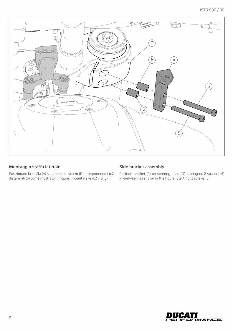
Side bracket assembly
Position bracket (4) on steering head (D) placing no.2 spacers (6) in-between, as shown in the figure. Start no. 2 screws (5).
Montaggio staffa laterale
Posizionare la staffa (4) sulla testa di sterzo (D) interponendo i n.2 distanziali (6) come mostrato in figura. Impuntare le n.2 viti (5).
6
ISTR 986 / 00
6
6
D
6
4
5
5
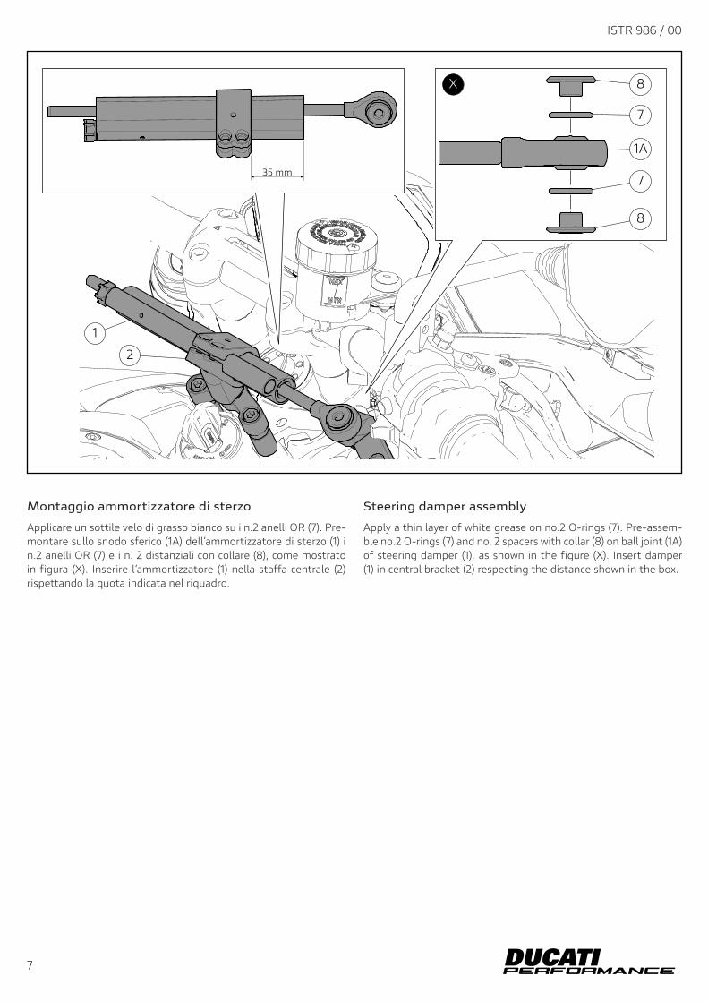
Steering damper assembly
Apply a thin layer of white grease on no.2 O-rings (7). Pre-assem-ble no.2 O-rings (7) and no. 2 spacers with collar (8) on ball joint (1A) of steering damper (1), as shown in the figure (X). Insert damper (1) in central bracket (2) respecting the distance shown in the box.
Montaggio ammortizzatore di sterzo
Applicare un sottile velo di grasso bianco su i n.2 anelli OR (7). Pre-montare sullo snodo sferico (1A) dell’ammortizzatore di sterzo (1) i n.2 anelli OR (7) e i n. 2 distanziali con collare (8), come mostrato in figura (X). Inserire l’ammortizzatore (1) nella staffa centrale (2) rispettando la quota indicata nel riquadro.
ISTR 986 / 00
7
1
2
8
7
1A
7
8
X
35 mm
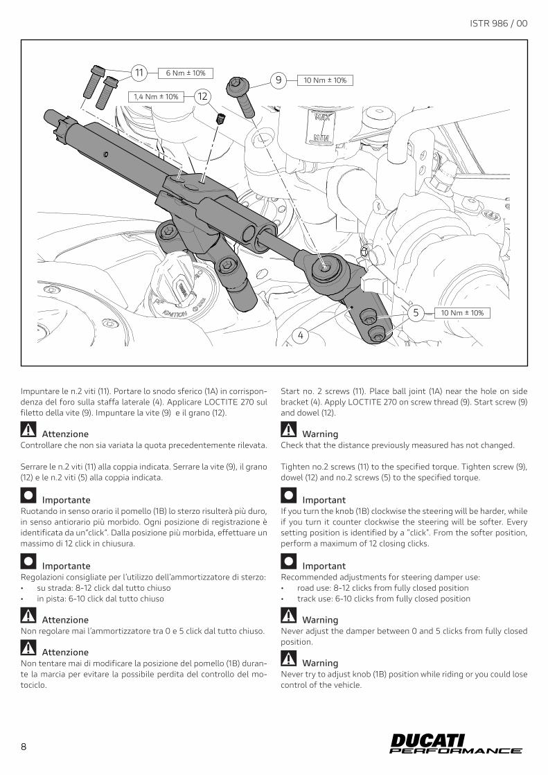
Start no. 2 screws (11). Place ball joint (1A) near the hole on side bracket (4). Apply LOCTITE 270 on screw thread (9). Start screw (9) and dowel (12).
WarningCheck that the distance previously measured has not changed.
Tighten no.2 screws (11) to the specified torque. Tighten screw (9), dowel (12) and no.2 screws (5) to the specified torque.
ImportantIf you turn the knob (1B) clockwise the steering will be harder, while if you turn it counter clockwise the steering will be softer. Every setting position is identified by a "click". From the softer position, perform a maximum of 12 closing clicks.
ImportantRecommended adjustments for steering damper use: • road use: 8-12 clicks from fully closed position• track use: 6-10 clicks from fully closed position
WarningNever adjust the damper between 0 and 5 clicks from fully closed position.
WarningNever try to adjust knob (1B) position while riding or you could lose control of the vehicle.
Impuntare le n.2 viti (11). Portare lo snodo sferico (1A) in corrispon-denza del foro sulla staffa laterale (4). Applicare LOCTITE 270 sul filetto della vite (9). Impuntare la vite (9) e il grano (12).
AttenzioneControllare che non sia variata la quota precedentemente rilevata.
Serrare le n.2 viti (11) alla coppia indicata. Serrare la vite (9), il grano (12) e le n.2 viti (5) alla coppia indicata.
ImportanteRuotando in senso orario il pomello (1B) lo sterzo risulterà più duro, in senso antiorario più morbido. Ogni posizione di registrazione è identificata da un“click“. Dalla posizione più morbida, effettuare un massimo di 12 click in chiusura.
ImportanteRegolazioni consigliate per l’utilizzo dell’ammortizzatore di sterzo: • su strada: 8-12 click dal tutto chiuso• in pista: 6-10 click dal tutto chiuso
AttenzioneNon regolare mai l’ammortizzatore tra 0 e 5 click dal tutto chiuso.
AttenzioneNon tentare mai di modificare la posizione del pomello (1B) duran-te la marcia per evitare la possibile perdita del controllo del mo-tociclo.
1 P/N 商品名
2 P/N 商品名
3 P/N 商品名
4 P/N 商品名
5 P/N 商品名
ご注文商品レース専用部品 ご注文書
モデル名
ご注文日
販売日 年 月 日
1. 上記ご記入の上、弊社アフターセールス部までFAXしてください。FAX : 03 - 6692 - 1317
お客様ご記入欄私は上記レース専用部品を下記車両に装着し、サーキット走行のみに利用し、一般公道には利用しません。
販売店署名
販売店様へお願い
車台番号 ZDM
お客様署名
ドゥカティ正規ネットワーク店記入欄お客様に上記レース専用部品を販売し、レース専用部品のご利用方法を説明いたしました。
1. 上記ご記入の上、弊社アフターセールス部までFAXしてください。FAX : 03 - 6692 - 13172. 取り付け車両1台に1枚でご使用ください。
8
ISTR 986 / 00
8
9
5
11
10 Nm ± 10%
4
10 Nm ± 10%
121,4 Nm ± 10%
6 Nm ± 10%