Embed Size (px)
Citation preview
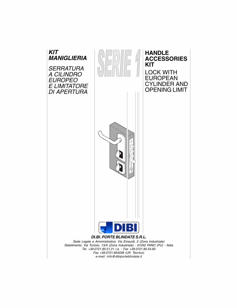
KITMANIGLIERIA
SERRATURAA CILINDROEUROPEOE LIMITATOREDI APERTURA
HANDLEACCESSORIESKITLOCK WITHEUROPEANCYLINDER ANDOPENING LIMIT
DI.BI. PORTE BLINDATE S.R.L.Sede Legale e Amministrativa: Via Einauidi, 2 (Zona Industriale)
Stabilimento: Via Toniolo, 13/A (Zona Industriale) - 61032 FANO (PU) - ItaliaTel. +39.0721.85.51.21 r.a. - Fax +39.0721.85.54.60
Fax +39.0721.854038 (Uff. Tecnico)e-mail: [email protected]

3
CONTENUTO SCATOLA
OPERAZIONIPRELIMINARI
CONTROLLI
CONTENUTOSCATOLA ACCESSORI
ATTREZZI
SMONTAGGIONUCLEO DI SERVIZIO
MONTAGGIO DEFENDER
MONTAGGIONUCLEO E CILINDRO
MONTAGGIO ACCESSORILATO INTERNO
MONTAGGIOPOMOLO FISSO
MONTAGGIO POMOLOO MANIGLIA PASSANTEGIREVOLE
MONTAGGIOOCCHIO MAGICO
CONCLUSIONI
1
2
3
4
5
6
7
8
9
10
11
12
TITOLO CAPITOLOCHAPTER
PAGINAPAGE
4
6
6
6
6
7
8
9
14
18
20
22
23
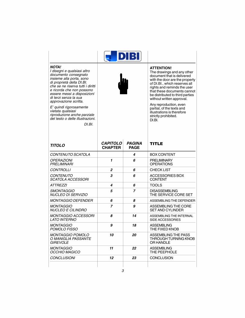
NOTA!I disegni e qualsiasi altrodocumento consegnatoinsieme alla porta, sonodi proprietà della DI.BI.che se ne riserva tutti i dirittie ricorda che non possonoessere messi a disposizionidi terzi senza la suaapprovazione scritta.
E’ quindi rigorosamentevietata qualsiasiriproduzione anche parzialedel testo o delle illustrazioni.
DI.BI.
ATTENTION!The drawings and any otherdocument that is deliveredwith the door are the propertyof DI.BI., which reserves allrights and reminds the userthat these documents cannotbe distributed to third partieswithout written approval.
Any reproduction, evenpartial, of the texts andillustrations is thereforestrictly prohibited.DI.BI.
BOX CONTENT
PRELIMINARYOPERATIONS
CHECK LIST
ACCESSORIES BOXCONTENT
TOOLS
DISASSEMBLINGTHE SERVICE CORE SET
ASSEMBLING THE DEFENDER
ASSEMBLING THE CORESET AND CYLINDER
ASSEMBLING THE INTERNALSIDE ACCESSORIES
ASSEMBLINGTHE FIXED KNOB
ASSEMBLING THE PASSTHROUGH TURNING KNOBOR HANDLE
ASSEMBLINGTHE PEEPHOLE
CONCLUSION
TITLE
4
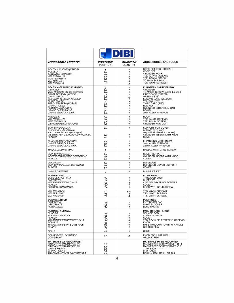
ACCESSORI E ATTREZZI
SCATOLA NUCLEO (VERDE)NUCLEOAGGANCIO CILINDROVITI TCEI M4x12VITE TSEI M5x14VITI TC M4x6VITI TCEI M6x8
SCATOLA CILINDRO EUROPEOCILINDROVITE TS M5x80 (da non utilizzare)PRIMA TESSERA (VERDE)CHIAVI VERDISECONDA TESSERA (GIALLA)CHIAVI GIALLETERZA TESSERA (ROSSA)CHIAVE ROSSAPROLUNGA CILINDROGRANO DI FISSAGGIOCHIAVE BRUGOLA 2 mm.
AGGANCIOVITI TCEI M4x12VITE TSEI M5x14CILINDRO PER LIMITATORE
SUPPORTO PLACCA(+ serrandina da utilizzaresolo con nucleo a doppia mappa)INSERTO PER CILINDRO CON POMOLOPLACCA
QUADRO AD ESPANSIONECHIAVE BRUGOLA 3 mm.CHIAVE BRUGOLA 2,5 mm.
MANIGLIA CON GRANO
SUPPORTO PLACCAINSERTO PER CILINDRO CON POMOLOPLACCA
DEFENDERSUPPORTO PLACCA DEFENDERPLACCA
CHIAVE CANTIERE
POMOLO FISSOBOCCOLA FILETTATASUPPORTOVITI AUTOFILETTANTI 4x25PLACCAPOMOLO CON GRANO
VITI TPS M4x30VITI TPS M4x27VITI TPS M4x14
OCCHIO MAGICOPROLUNGAOSCURANTEPORTALENTE
POMOLO PASSANTEQUADROSUPPORTO PLACCAPLACCAVITI AUTOFILETTANTI TPS 3,2x15POMOLOMANIGLIA PASSANTE GIREVOLEGRANO
COLLA
POMOLO PER LIMITATORECON GRANO
MATERIALE DA PROCURARSICACCIAVITE CALAMITATO Ø 4CACCIAVITE CALAMITATO Ø 6CHIAVE FISSA 7CHIAVE FISSA 8TRAPANO + PUNTA DA FERRO Ø 3
QUANTITA’QUANTITY
1113132
111151511111
1211
1
11
111
1
111
111
1
11411
9+444
111
1114111
1
2
POSIZIONEPOSITION
11a1b1c1d1e1f
22a2b2c2d2e2f2g2h2i2j2k
3a3b3c3d
4a
4b4c
5a5b5c
6
7a7b7c
8a8b8c
9
10a10b10c10d10e
1111a11b
12a12b12c
13a13b13c13d13e13f13g
14
15
5152535455
ACCESSORIES AND TOOLS
CORE SET BOX (GREEN)CORE SETCYLINDER HOOKTCEI M4X12 SCREWSTSEI M5X14 SCREWTC M4x6 SCREWSTCEI M6X8 SCREWS
EUROPEAN CYLINDER BOXCYLINDERTS M5X80 SCREW (not to be used)FIRST CARD (GREEN)GREEN KEYSSECOND CARD (YELLOW)YELLOW KEYSTHIRD CARD (RED)RED KEYCYLINDER EXTENSION BARDOWEL2mm ALLEN WRENCH
HOOKTCEI M4x12 SCREWSTSEI M5x14 SCREWCYLINDER FOR LIMIT
SUPPORT FOR COVER(+ blinds to be usedonly with double-slot core set)CYLINDER INSERT WITH KNOBCOVER
EXPANDING MECHANISM3mm ALLEN WRENCH2.5mm ALLEN WRENCH
HANDLE WITH GRUB SCREW
COVER SUPPORTCYLINDER INSERT WITH KNOBCOVER
DEFENDERDEFENDER COVER SUPPORTCOVER
BUILDER’S KEY
FIXED KNOBTHREADED BUSHSUPPORT4x25 SELF-TAPPING SCREWSCOVERKNOB WITH GRUB SCREW
TPS M4x30 SCREWSTPS M4x27 SCREWSTPS M4x14 SCREWS
PEEPHOLEEXTENSION BARLIGHT BLOCKERLENS CASING
PASS THROUGH KNOBSQUARE RODCOVER SUPPORTCOVERTPS 3.2x15 SELF-TAPPING SCREWSKNOBPASS THROUGH TURNING HANDLEGRUB SCREW
GLUE
KNOB FOR LIMIT WITHGRUB SCREW
MATERIALS TO BE PROCUREDMAGNETIZED SCREWDRIVER Ø 4MAGNETIZED SCREWDRIVER Ø 67” WRENCH8” WRENCHDRILL + IRON DRILL BIT Ø 3
1 1a
1b
1f 1c1d1e
14
2 5b5c
12a
12b 12c
2c
2d
2g2h
2e2f
51 53 52 54
55 3m m
10a
10b10c
10d
10e
3d
3a3b
3c
5a 1f
9
8c
8a
8b
1111a11b
4a
4c
6
7c
11
15 7b
4b
11
7a15
2a2k
2j
2i
13a
13c13b
13d 13g
13e
13g
13f
6
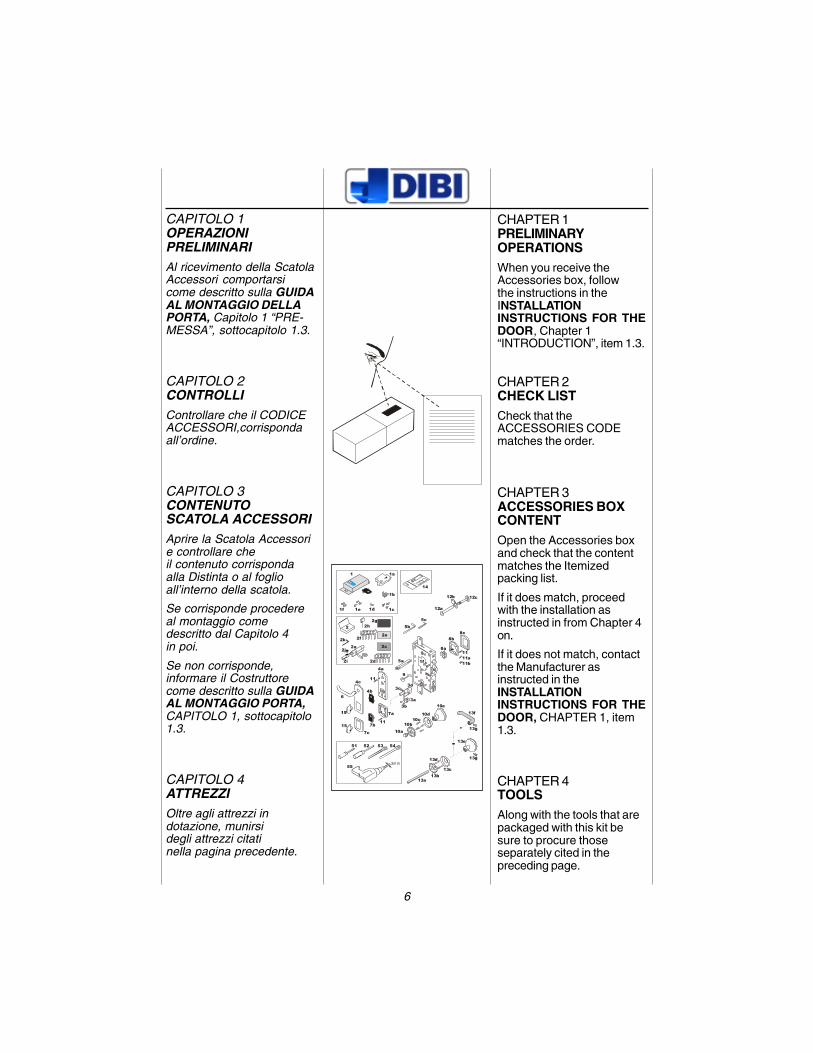
CAPITOLO 1OPERAZIONIPRELIMINARIAl ricevimento della ScatolaAccessori comportarsicome descritto sulla GUIDAAL MONTAGGIO DELLAPORTA, Capitolo 1 “PRE-MESSA”, sottocapitolo 1.3.
CAPITOLO 2CONTROLLIControllare che il CODICEACCESSORI,corrispondaall’ordine.
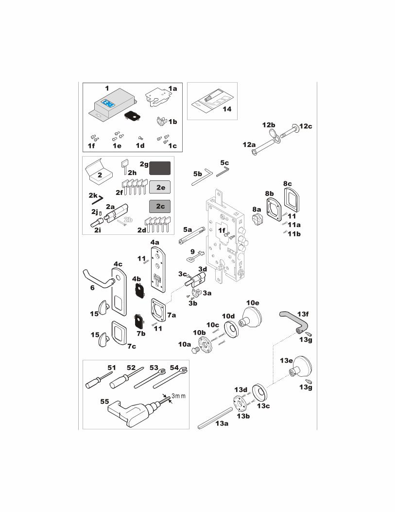
CAPITOLO 3CONTENUTOSCATOLA ACCESSORIAprire la Scatola Accessorie controllare cheil contenuto corrispondaalla Distinta o al foglioall’interno della scatola.
Se corrisponde procedereal montaggio comedescritto dal Capitolo 4in poi.
Se non corrisponde,informare il Costruttorecome descritto sulla GUIDAAL MONTAGGIO PORTA,CAPITOLO 1, sottocapitolo1.3.
CAPITOLO 4ATTREZZIOltre agli attrezzi indotazione, munirsidegli attrezzi citatinella pagina precedente.
1 1a
1b
1f 1c1d1e
14
2 5b5c
12a
12b 12c
2c
2d
2g2h
2e2f
51 53 52 54
55 3m m
10a10b
10c10d
10e
3d
3a3b
3c
5a 1f
9
8c
8a
8b
1111a11b
4a
4c
6
7c
11
15 7b
4b
11
7a15
2a2k
2j
2i
13a
13c13b
13d 13g
13e
13g
13f
CHAPTER 1PRELIMINARYOPERATIONSWhen you receive theAccessories box, followthe instructions in theINSTALLATIONINSTRUCTIONS FOR THEDOOR, Chapter 1“INTRODUCTION”, item 1.3.
CHAPTER 2CHECK LISTCheck that theACCESSORIES CODEmatches the order.
CHAPTER 3ACCESSORIES BOXCONTENTOpen the Accessories boxand check that the contentmatches the Itemizedpacking list.
If it does match, proceedwith the installation asinstructed in from Chapter 4on.
If it does not match, contactthe Manufacturer asinstructed in theINSTALLATIONINSTRUCTIONS FOR THEDOOR, CHAPTER 1, item1.3.
CHAPTER 4TOOLSAlong with the tools that arepackaged with this kit besure to procure thoseseparately cited in thepreceding page.
7
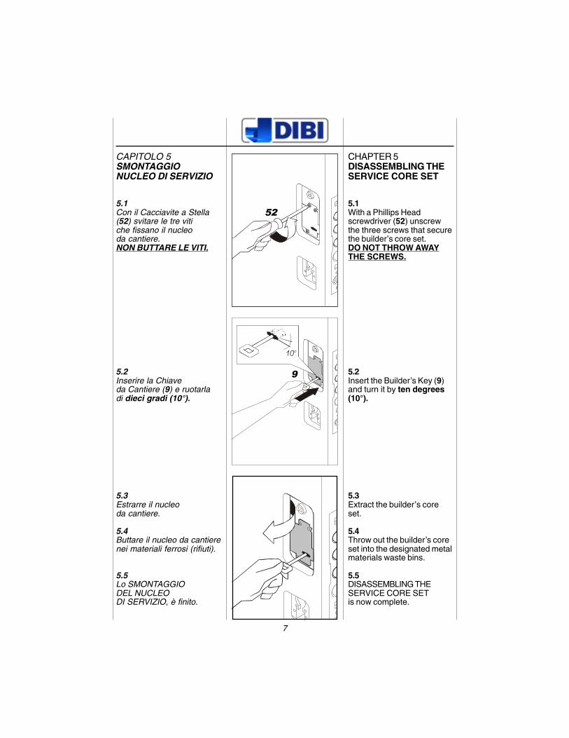
CAPITOLO 5SMONTAGGIONUCLEO DI SERVIZIO
5.1Con il Cacciavite a Stella(52) svitare le tre vitiche fissano il nucleoda cantiere.NON BUTTARE LE VITI.
5.2Inserire la Chiaveda Cantiere (9) e ruotarladi dieci gradi (10°).
5.3Estrarre il nucleoda cantiere.
5.4Buttare il nucleo da cantierenei materiali ferrosi (rifiuti).
5.5Lo SMONTAGGIODEL NUCLEODI SERVIZIO, è finito.
10°
52
9
CHAPTER 5DISASSEMBLING THESERVICE CORE SET
5.1With a Phillips Headscrewdriver (52) unscrewthe three screws that securethe builder’s core set.DO NOT THROW AWAYTHE SCREWS.
5.2Insert the Builder’s Key (9)and turn it by ten degrees(10°).
5.3Extract the builder’s coreset.
5.4Throw out the builder’s coreset into the designated metalmaterials waste bins.
5.5DISASSEMBLING THESERVICE CORE SETis now complete.
8
clack
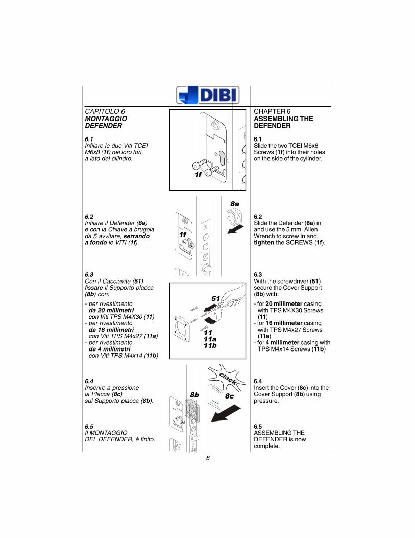
CAPITOLO 6MONTAGGIODEFENDER
6.1Infilare le due Viti TCEIM6x8 (1f) nei loro foria lato del cilindro.
6.2Infilare il Defender (8a)e con la Chiave a brugolada 5 avvitare, serrandoa fondo le VITI (1f).
6.3Con il Cacciavite (51)fissare il Supporto placca(8b) con:
- per rivestimentoda 20 millimetricon Viti TPS M4X30 (11)
- per rivestimentoda 16 millimetricon Viti TPS M4x27 (11a)
- per rivestimentoda 4 millimetricon Viti TPS M4x14 (11b)
6.4Inserire a pressionela Placca (8c)sul Supporto placca (8b).
6.5Il MONTAGGIODEL DEFENDER, è finito.
1f
8a
1f
51
1111a11b
8c8b
CHAPTER 6ASSEMBLING THEDEFENDER
6.1Slide the two TCEI M6x8Screws (1f) into their holeson the side of the cylinder.
6.2Slide the Defender (8a) inand use the 5 mm. AllenWrench to screw in and,tighten the SCREWS (1f).
6.3With the screwdriver (51)secure the Cover Support(8b) with:
- for 20 millimeter casingwith TPS M4X30 Screws(11)
- for 16 millimeter casingwith TPS M4x27 Screws(11a)
- for 4 millimeter casing withTPS M4x14 Screws (11b)
6.4Insert the Cover (8c) into theCover Support (8b) usingpressure.
6.5ASSEMBLING THEDEFENDER is nowcomplete.
9
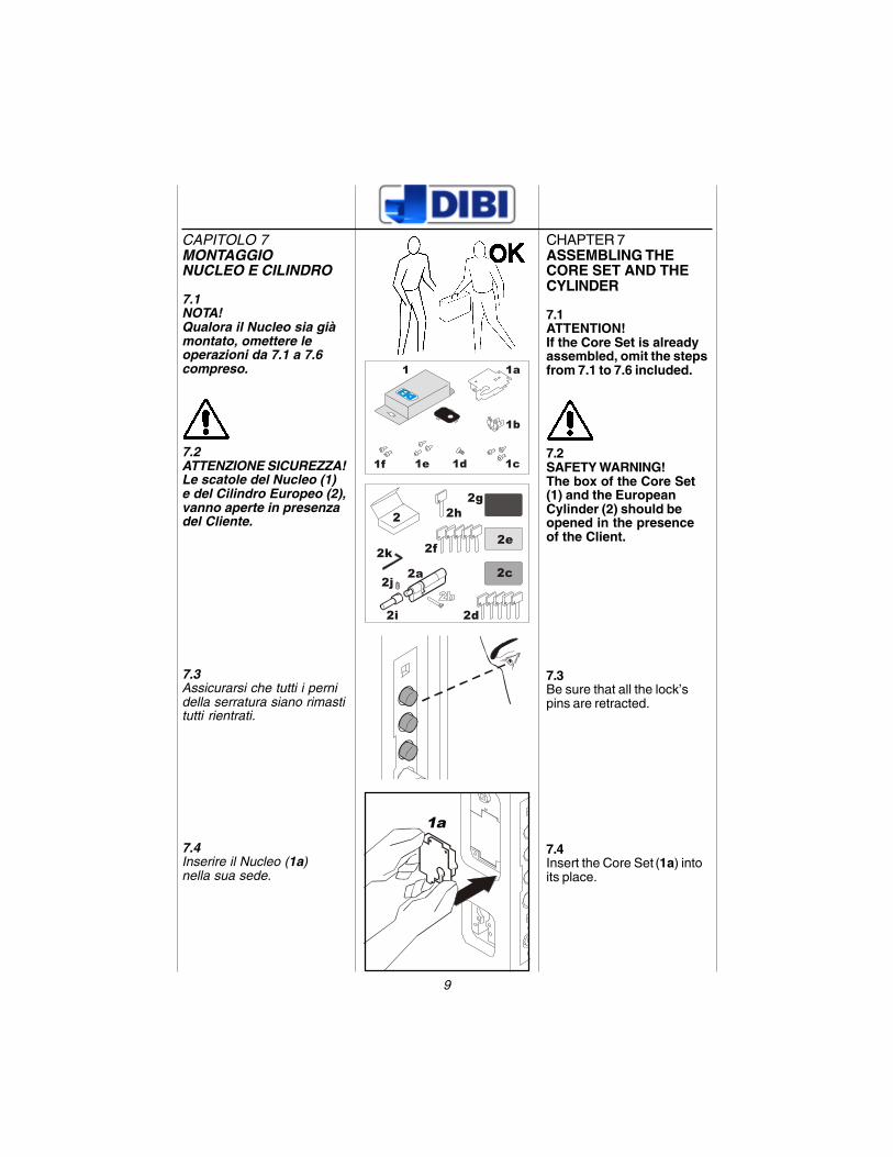
CAPITOLO 7MONTAGGIONUCLEO E CILINDRO
7.1NOTA!Qualora il Nucleo sia giàmontato, omettere leoperazioni da 7.1 a 7.6compreso.
7.2ATTENZIONE SICUREZZA!Le scatole del Nucleo (1)e del Cilindro Europeo (2),vanno aperte in presenzadel Cliente.
7.3Assicurarsi che tutti i pernidella serratura siano rimastitutti rientrati.
7.4Inserire il Nucleo (1a)nella sua sede.
1a
2
2c
2d
2g2h
2e2f
2a2k
2j
2i
1 1a
1b
1f 1c1d1e
CHAPTER 7ASSEMBLING THECORE SET AND THECYLINDER
7.1ATTENTION!If the Core Set is alreadyassembled, omit the stepsfrom 7.1 to 7.6 included.
7.2SAFETY WARNING!The box of the Core Set(1) and the EuropeanCylinder (2) should beopened in the presenceof the Client.
7.3Be sure that all the lock’spins are retracted.
7.4Insert the Core Set
(1a) into
its place.
10
1a1e
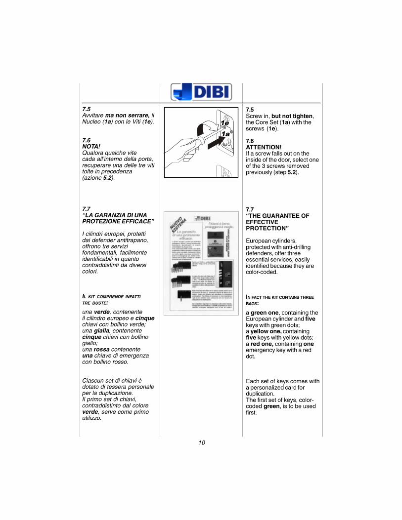
7.5Avvitare ma non serrare, ilNucleo (1a) con le Viti (1e).
7.6NOTA!Qualora qualche vitecada all’interno della porta,recuperare una delle tre vititolte in precedenza(azione 5.2).
7.7“LA GARANZIA DI UNAPROTEZIONE EFFICACE”
I cilindri europei, protettidai defender antitrapano,offrono tre servizifondamentali, facilmenteidentificabili in quantocontraddistinti da diversicolori.
IL KIT COMPRENDE INFATTI
TRE BUSTE:
una verde, contenenteil cilindro europeo e cinquechiavi con bollino verde;una gialla, contenentecinque chiavi con bollinogiallo;una rossa contenenteuna chiave di emergenzacon bollino rosso.
Ciascun set di chiavi èdotato di tessera personaleper la duplicazione.Il primo set di chiavi,contraddistinto dal coloreverde, serve come primoutilizzo.
7.5Screw in, but not tighten,the Core Set (1a) with thescrews (1e).
7.6ATTENTION!If a screw falls out on theinside of the door, select oneof the 3 screws removedpreviously (step 5.2).
7.7“THE GUARANTEE OFEFFECTIVEPROTECTION”
European cylinders,protected with anti-drillingdefenders, offer threeessential services, easilyidentified because they arecolor-coded.
IN FACT THE KIT CONTAINS THREE
BAGS:
a green one, containing theEuropean cylinder and fivekeys with green dots;a yellow one, containingfive keys with yellow dots;a red one, containing oneemergency key with a reddot.
Each set of keys comes witha personalized card forduplication.The first set of keys, color-coded green, is to be usedfirst.
11
2a
1b
5b
1d
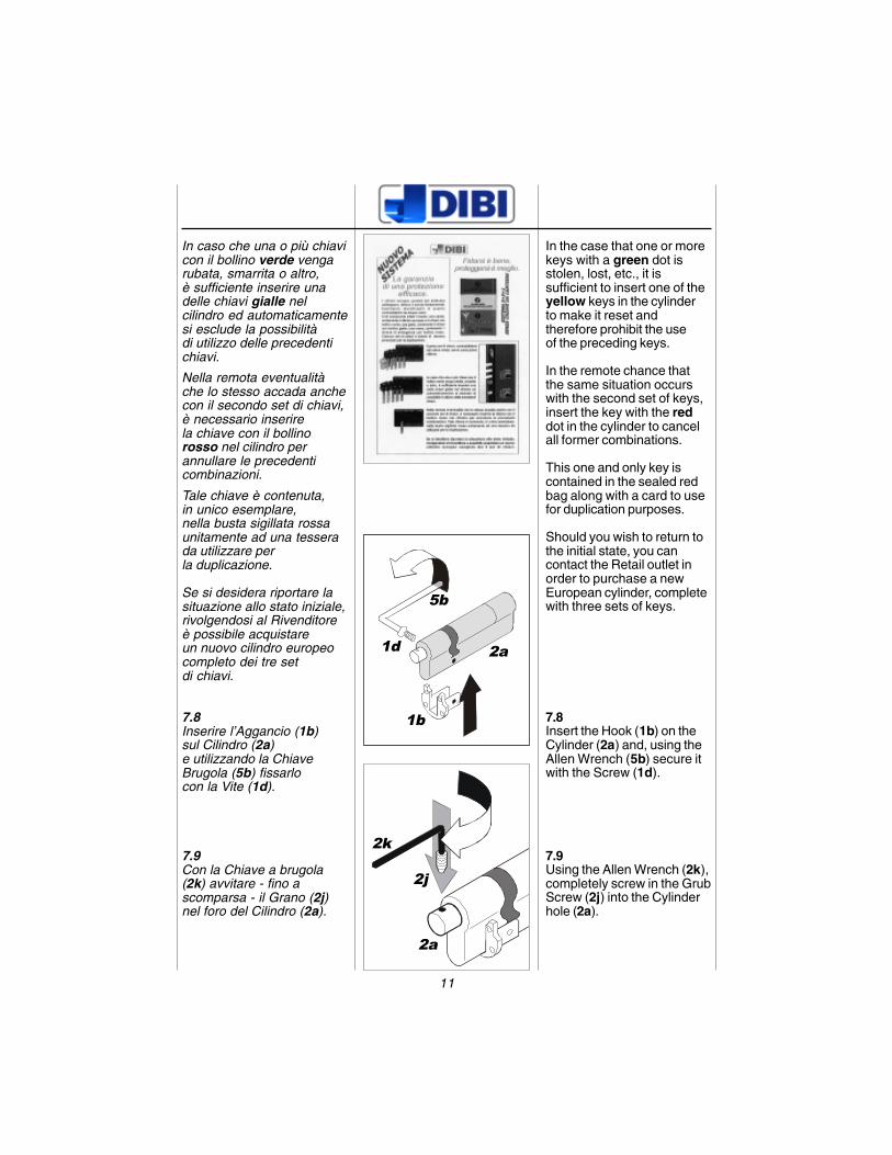
In caso che una o più chiavicon il bollino verde vengarubata, smarrita o altro,è sufficiente inserire unadelle chiavi gialle nelcilindro ed automaticamentesi esclude la possibilitàdi utilizzo delle precedentichiavi.
Nella remota eventualitàche lo stesso accada anchecon il secondo set di chiavi,è necessario inserirela chiave con il bollinorosso nel cilindro perannullare le precedenticombinazioni.
Tale chiave è contenuta,in unico esemplare,nella busta sigillata rossaunitamente ad una tesserada utilizzare perla duplicazione.
Se si desidera riportare lasituazione allo stato iniziale,rivolgendosi al Rivenditoreè possibile acquistareun nuovo cilindro europeocompleto dei tre setdi chiavi.
7.8Inserire l’Aggancio (1b)sul Cilindro (2a)e utilizzando la ChiaveBrugola (5b) fissarlocon la Vite (1d).
7.9Con la Chiave a brugola(2k) avvitare - fino ascomparsa - il Grano (2j)nel foro del Cilindro (2a).
2k
2j
2a
In the case that one or morekeys with a green dot isstolen, lost, etc., it issufficient to insert one of theyellow keys in the cylinderto make it reset andtherefore prohibit the useof the preceding keys.
In the remote chance thatthe same situation occurswith the second set of keys,insert the key with the reddot in the cylinder to cancelall former combinations.
This one and only key iscontained in the sealed redbag along with a card to usefor duplication purposes.
Should you wish to return tothe initial state, you cancontact the Retail outlet inorder to purchase a newEuropean cylinder, completewith three sets of keys.
7.8Insert the Hook (1b) on theCylinder (2a) and, using theAllen Wrench (5b) secure itwith the Screw (1d).
7.9Using the Allen Wrench (2k),completely screw in the GrubScrew (2j) into the Cylinderhole (2a).
12
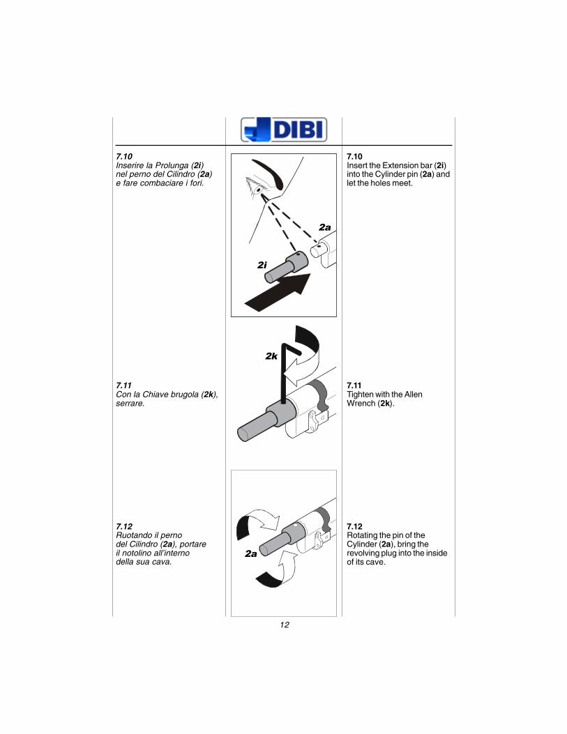
7.10Inserire la Prolunga (2i)nel perno del Cilindro (2a)e fare combaciare i fori.
7.11Con la Chiave brugola (2k),serrare.
7.12Ruotando il pernodel Cilindro (2a), portareil notolino all’internodella sua cava.
2i
2a
2a
2k
7.10Insert the Extension bar (2i)into the Cylinder pin (2a) andlet the holes meet.
7.11Tighten with the AllenWrench (2k).
7.12Rotating the pin of theCylinder (2a), bring therevolving plug into the insideof its cave.
13
OK
2d
2a
5b 1c
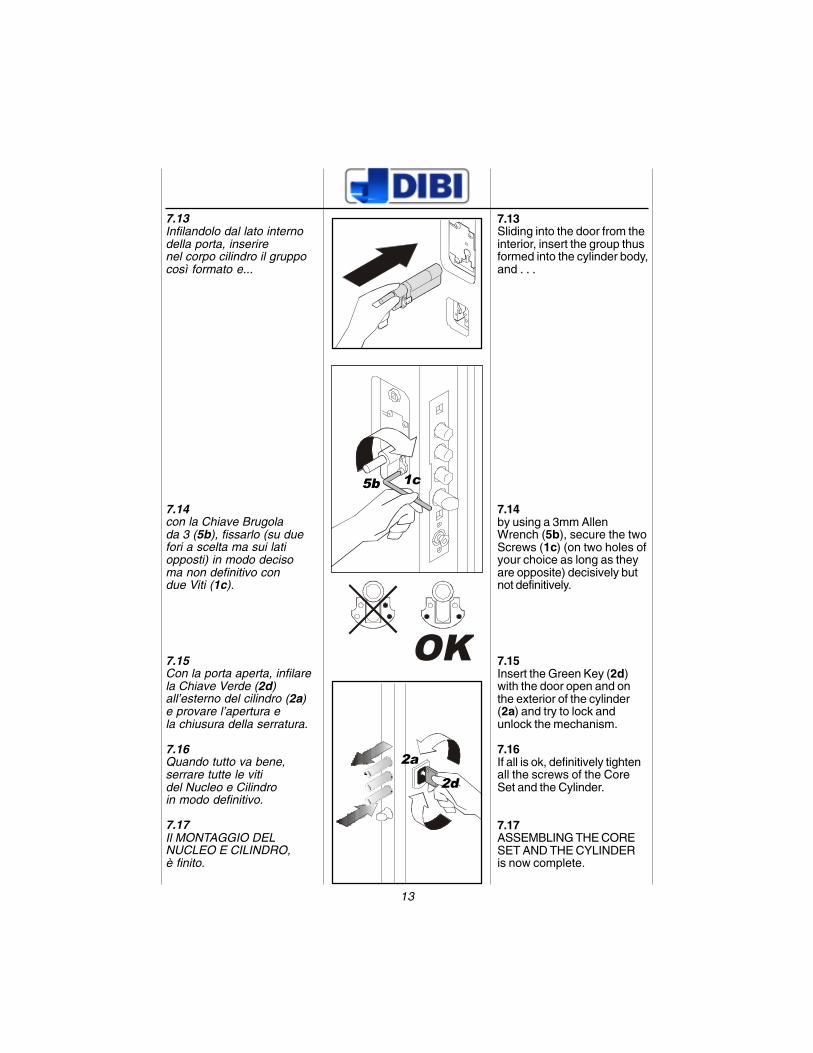
7.13Infilandolo dal lato internodella porta, inserirenel corpo cilindro il gruppocosì formato e...
7.14con la Chiave Brugolada 3 (5b), fissarlo (su duefori a scelta ma sui latiopposti) in modo decisoma non definitivo condue Viti (1c).
7.15Con la porta aperta, infilarela Chiave Verde (2d)all’esterno del cilindro (2a)e provare l’apertura ela chiusura della serratura.
7.16Quando tutto va bene,serrare tutte le vitidel Nucleo e Cilindroin modo definitivo.
7.17Il MONTAGGIO DELNUCLEO E CILINDRO,è finito.
7.13Sliding into the door from theinterior, insert the group thusformed into the cylinder body,and . . .
7.14by using a 3mm AllenWrench (5b), secure the twoScrews (1c) (on two holes ofyour choice as long as theyare opposite) decisively butnot definitively.
7.15Insert the Green Key (2d)with the door open and onthe exterior of the cylinder(2a) and try to lock andunlock the mechanism.
7.16If all is ok, definitively tightenall the screws of the CoreSet and the Cylinder.
7.17ASSEMBLING THE CORESET AND THE CYLINDERis now complete.
14
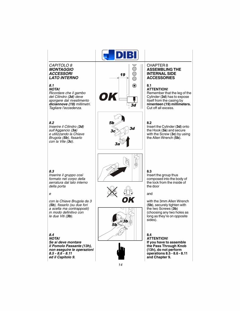
CAPITOLO 8MONTAGGIOACCESSORILATO INTERNO
8.1NOTA!Ricordare che il gambodel Cilindro (3d) devesporgere dal rivestimentodiciannove (19) millimetri.Tagliare l’eccedenza.
8.2Inserire il Cilindro (3d)sull’Aggancio (3a)e utilizzando la ChiaveBrugola (5b), fissarlocon la Vite (3c).
8.3Inserire il gruppo cosìformato nel corpo dellaserratura dal lato internodella porta
e
con la Chiave Brugola da 3(5b), fissarlo (su due foria scelta ma contrapposti)in modo definitivo conle due Viti (3b).
8.4NOTA!Se si deve montareil Pomolo Passante (13h),non eseguire le operazioni8.5 - 8.6 - 8.11ed il Capitolo 9.
OK
OK
19
3d
3d5b
3c
5b3b
3a
CHAPTER 8ASSEMBLING THEINTERNAL SIDEACCESSORIES
8.1ATTENTION!Remember that the leg of theCylinder (3d) has to exposeitself from the casing byninenteen (19) millimeters.Cut off all excess.
8.2Insert the Cylinder (3d) ontothe Hook (3a) and securewith the Screw (3c) by usingthe Allen Wrench (5b).
8.3Insert the group thuscomposed into the body ofthe lock from the inside ofthe door
and
with the 3mm Allen Wrench(5b), securely tighten withthe two Screws (3b)(choosing any two holes aslong as they’re on oppositesides).
8.4ATTENTION!If you have to assemblethe Pass Through Knob(13h), do not performoperations 8.5 - 8.6 - 8.11and Chapter 9.
15
clack
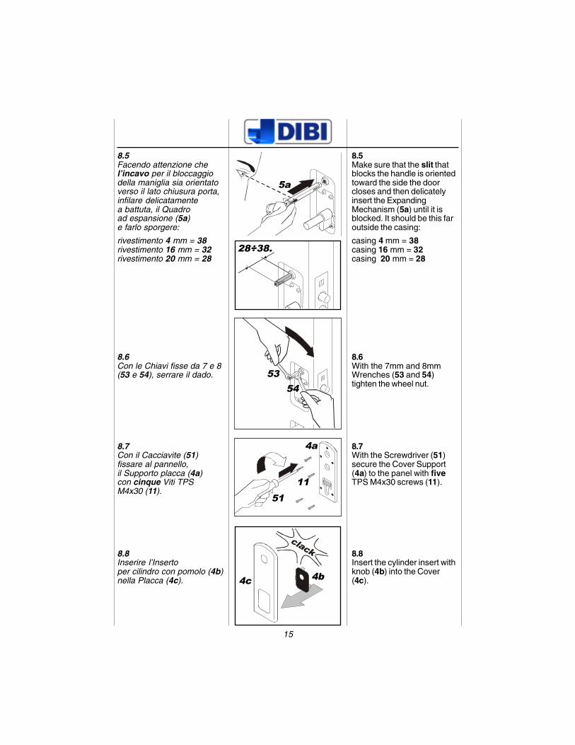
8.5Facendo attenzione chel’incavo per il bloccaggiodella maniglia sia orientatoverso il lato chiusura porta,infilare delicatamentea battuta, il Quadroad espansione (5a)e farlo sporgere:
rivestimento 4 mm = 38rivestimento 16 mm = 32rivestimento 20 mm = 28
8.6Con le Chiavi fisse da 7 e 8(53 e 54), serrare il dado.
8.7Con il Cacciavite (51)fissare al pannello,il Supporto placca (4a)con cinque Viti TPSM4x30 (11).
8.8Inserire l’Insertoper cilindro con pomolo (4b)nella Placca (4c).
5a
28÷38.
5354
4b
5111
4a
4c
8.5Make sure that the slit thatblocks the handle is orientedtoward the side the doorcloses and then delicatelyinsert the ExpandingMechanism (5a) until it isblocked. It should be this faroutside the casing:
casing 4 mm = 38casing 16 mm = 32casing 20 mm = 28
8.6With the 7mm and 8mmWrenches (53 and 54)tighten the wheel nut.
8.7With the Screwdriver (51)secure the Cover Support(4a) to the panel with fiveTPS M4x30 screws (11).
8.8Insert the cylinder insert withknob (4b) into the Cover(4c).
16
clack
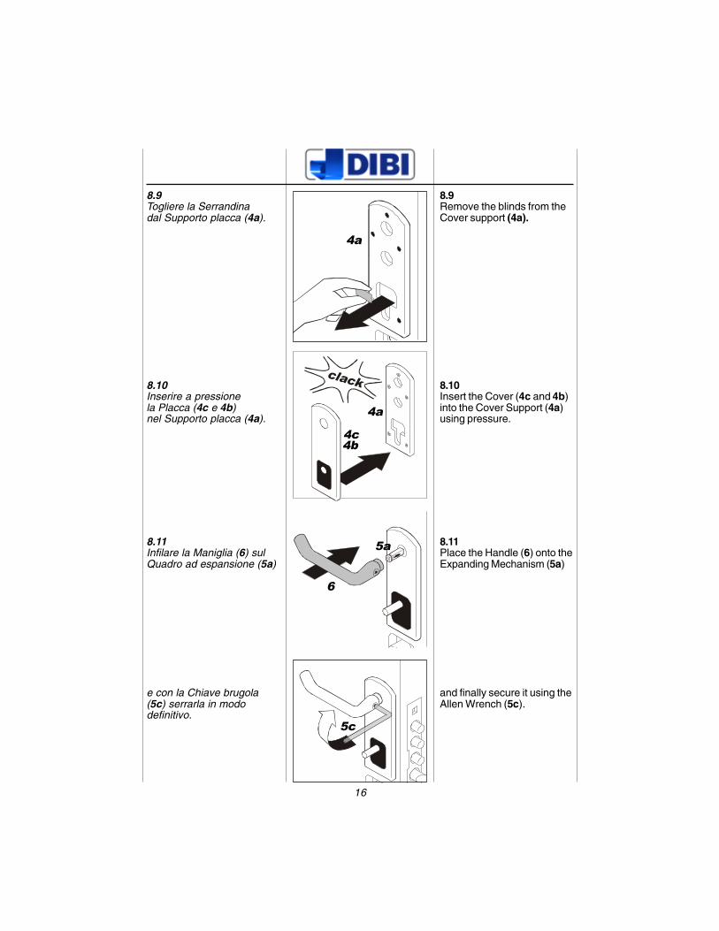
8.9Togliere la Serrandinadal Supporto placca (4a).
8.10Inserire a pressionela Placca (4c e 4b)nel Supporto placca (4a).
8.11Infilare la Maniglia (6) sulQuadro ad espansione (5a)
e con la Chiave brugola(5c) serrarla in mododefinitivo.
4a
4c
4a
6
4b
5c
5a
8.9Remove the blinds from theCover support (4a).
8.10Insert the Cover (4c and 4b)into the Cover Support (4a)using pressure.
8.11Place the Handle (6) onto theExpanding Mechanism (5a)
and finally secure it using theAllen Wrench (5c).
17
clack
clack
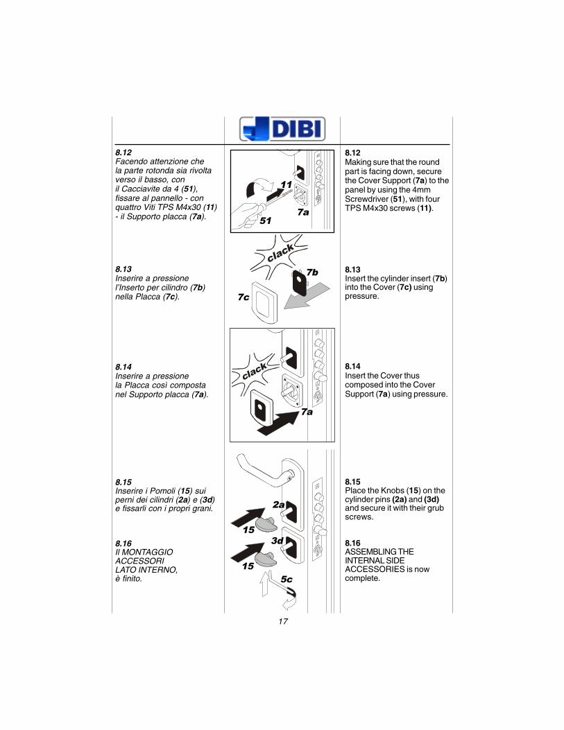
8.12Facendo attenzione chela parte rotonda sia rivoltaverso il basso, conil Cacciavite da 4 (51),fissare al pannello - conquattro Viti TPS M4x30 (11)- il Supporto placca (7a).
8.13Inserire a pressionel’Inserto per cilindro (7b)nella Placca (7c).
8.14Inserire a pressionela Placca così compostanel Supporto placca (7a).
8.15Inserire i Pomoli (15) suiperni dei cilindri (2a) e (3d)e fissarli con i propri grani.
8.16Il MONTAGGIOACCESSORILATO INTERNO,è finito.
51
7b
11
7c
15
7a
7a
15
2a
3d
5c
8.12Making sure that the roundpart is facing down, securethe Cover Support (7a) to thepanel by using the 4mmScrewdriver (51), with fourTPS M4x30 screws (11).
8.13Insert the cylinder insert (7b)into the Cover (7c) usingpressure.
8.14Insert the Cover thuscomposed into the CoverSupport (7a) using pressure.
8.15Place the Knobs (15) on thecylinder pins (2a) and (3d)and secure it with their grubscrews.
8.16ASSEMBLING THEINTERNAL SIDEACCESSORIES is nowcomplete.
18
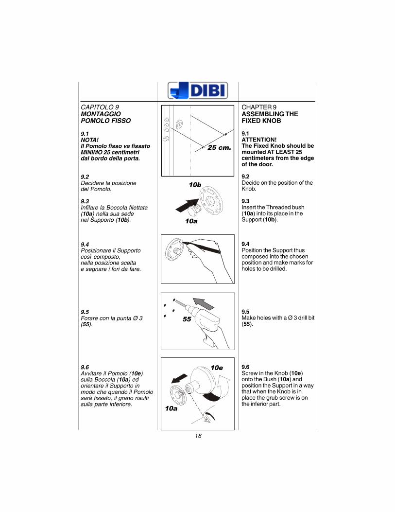
CAPITOLO 9MONTAGGIOPOMOLO FISSO
9.1NOTA!Il Pomolo fisso va fissatoMINIMO 25 centimetridal bordo della porta.
9.2Decidere la posizionedel Pomolo.
9.3Infilare la Boccola filettata(10a) nella sua sedenel Supporto (10b).
9.4Posizionare il Supportocosì composto,nella posizione sceltae segnare i fori da fare.
9.5Forare con la punta Ø 3(55).
9.6Avvitare il Pomolo (10e)sulla Boccola (10a) edorientare il Supporto inmodo che quando il Pomolosarà fissato, il grano risultisulla parte inferiore.
25 cm.
10a
10b
55
10e
10a
CHAPTER 9ASSEMBLING THEFIXED KNOB
9.1ATTENTION!The Fixed Knob should bemounted AT LEAST 25centimeters from the edgeof the door.
9.2Decide on the position of theKnob.
9.3Insert the Threaded bush(10a) into its place in theSupport (10b).
9.4Position the Support thuscomposed into the chosenposition and make marks forholes to be drilled.
9.5Make holes with a Ø 3 drill bit(55).
9.6Screw in the Knob (10e)onto the Bush (10a) andposition the Support in a waythat when the Knob is inplace the grub screw is onthe inferior part.
19
clack
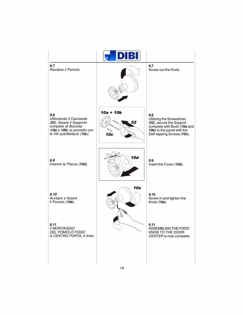
9.7Risvitare il Pomolo.
9.8Utilizzando il Cacciavite(52), fissare il Supportocompleto di Boccola(10a e 10b) al pannello conle Viti autofilettanti (10c).
9.9Inserire la Placca (10d).
9.10Avvitare e fissareil Pomolo (10e).
9.11Il MONTAGGIODEL POMOLO FISSOA CENTRO PORTA, è finito.
52
10a + 10b
10c
10d
10e
9.7Screw out the Knob.
9.8Utilizing the Screwdriver(52), secure the Supportcomplete with Bush (10a and10b) to the panel with theSelf-tapping Screws (10c).
9.9Insert the Cover (10d).
9.10Screw in and tighten theKnob (10e).
9.11ASSEMBLING THE FIXEDKNOB TO THE DOORCENTER is now complete.
20
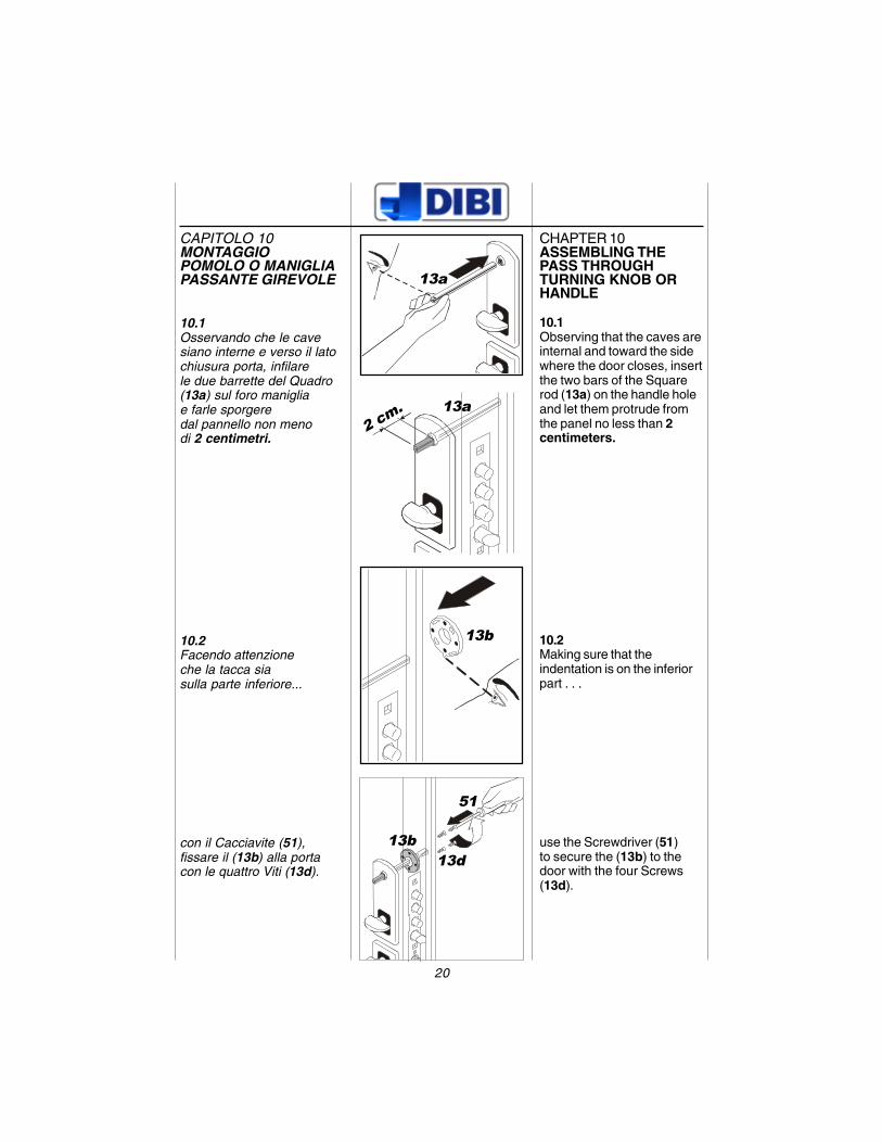
CAPITOLO 10MONTAGGIOPOMOLO O MANIGLIAPASSANTE GIREVOLE
10.1Osservando che le cavesiano interne e verso il latochiusura porta, infilarele due barrette del Quadro(13a) sul foro manigliae farle sporgeredal pannello non menodi 2 centimetri.
10.2Facendo attenzioneche la tacca siasulla parte inferiore...
con il Cacciavite (51),fissare il (13b) alla portacon le quattro Viti (13d).
51
13d13b
13a
2 cm. 13a
13b
CHAPTER 10ASSEMBLING THEPASS THROUGHTURNING KNOB ORHANDLE
10.1Observing that the caves areinternal and toward the sidewhere the door closes, insertthe two bars of the Squarerod (13a) on the handle holeand let them protrude fromthe panel no less than 2centimeters.
10.2Making sure that theindentation is on the inferiorpart . . .
use the Screwdriver (51)to secure the (13b) to thedoor with the four Screws(13d).
21
clack
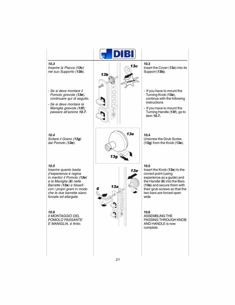
10.3Inserire la Placca (13c)nel suo Supporto (13b).
- Se si deve montare ilPomolo girevole (13e),continuare quì di seguito.
- Se si deve montare laManiglia girevole (13f),passare all’azione 10.7.
10.4Svitare il Grano (13g)dal Pomolo (13e).
10.5Inserire quanto basta(l’esperienza è reginain merito) il Pomolo (13e)e la Maniglia (6) nelleBarrette (13a) e fissarlicon i propri grani in modoche le due barrette sianoforzate ed allargate.
10.6Il MONTAGGIO DELPOMOLO PASSANTEE MANIGLIA, è finito.
13g
13e
13c
13b
13e
13a6
10.3Insert the Cover (13c) into itsSupport (13b).
- If you have to mount theTurning Knob (13e),continue with the followinginstructions
- If you have to mount theTurning Handle (13f), go toitem 10.7.
10.4Unscrew the Grub Screw(13g) from the Knob (13e).
10.5Insert the Knob (13e) to thecorrect point (usingexperience as a guide) andthe Handle (6) into the Bars(13a) and secure them withtheir grub screws so that thetwo bars are forced openwide
10.6ASSEMBLING THEPASSING THROUGH KNOBAND HANDLE is nowcomplete.
22
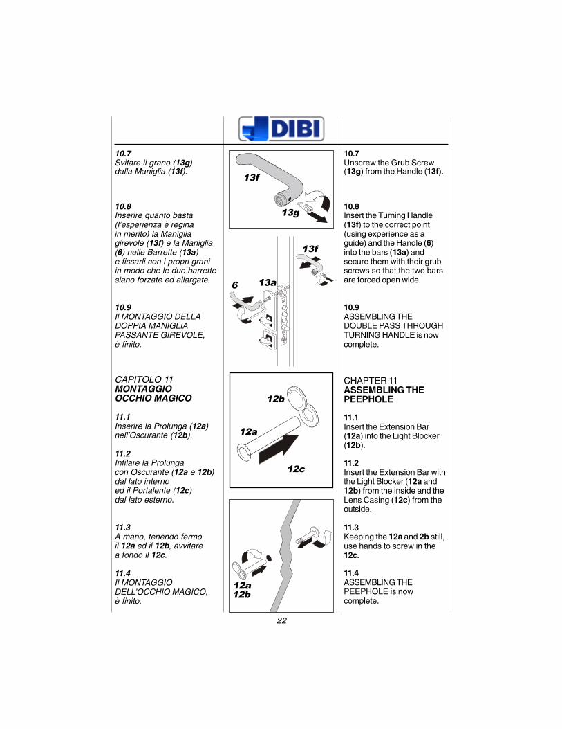
10.7Svitare il grano (13g)dalla Maniglia (13f).
10.8Inserire quanto basta(l’esperienza è reginain merito) la Manigliagirevole (13f) e la Maniglia(6) nelle Barrette (13a)e fissarli con i propri graniin modo che le due barrettesiano forzate ed allargate.
10.9Il MONTAGGIO DELLADOPPIA MANIGLIAPASSANTE GIREVOLE,è finito.
CAPITOLO 11MONTAGGIOOCCHIO MAGICO
11.1Inserire la Prolunga (12a)nell’Oscurante (12b).
11.2Infilare la Prolungacon Oscurante (12a e 12b)dal lato internoed il Portalente (12c)dal lato esterno.
11.3A mano, tenendo fermoil 12a ed il 12b, avvitarea fondo il 12c.
11.4Il MONTAGGIODELL’OCCHIO MAGICO,è finito.
13f
13g
12b
12a
12b
12a
12c
13f
6 13a
10.7Unscrew the Grub Screw(13g) from the Handle (13f).
10.8Insert the Turning Handle(13f) to the correct point(using experience as aguide) and the Handle (6)into the bars (13a) andsecure them with their grubscrews so that the two barsare forced open wide.
10.9ASSEMBLING THEDOUBLE PASS THROUGHTURNING HANDLE is nowcomplete.
CHAPTER 11ASSEMBLING THEPEEPHOLE
11.1Insert the Extension Bar(12a) into the Light Blocker(12b).
11.2Insert the Extension Bar withthe Light Blocker (12a and12b) from the inside and theLens Casing (12c) from theoutside.
11.3Keeping the 12a and 2b still,use hands to screw in the12c.
11.4ASSEMBLING THEPEEPHOLE is nowcomplete.
23
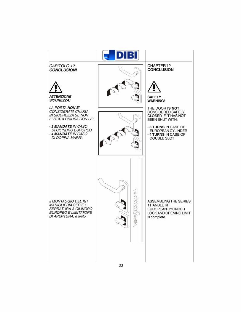
CAPITOLO 12CONCLUSIONI
ATTENZIONESICUREZZA!
LA PORTA NON E’CONSIDERATA CHIUSAIN SICUREZZA SE NONE’ STATA CHIUSA CON LE:
- 3 MANDATE IN CASODI CILINDRO EUROPEO
- 4 MANDATE IN CASODI DOPPIA MAPPA
Il MONTAGGIO DEL KITMANIGLIERIA SERIE 1SERRATURA A CILINDROEUROPEO E LIMITATOREDI APERTURA, è finito.
CHAPTER 12CONCLUSION
SAFETYWARNING!
THE DOOR IS NOTCONSIDERED SAFELYCLOSED IF IT HAS NOTBEEN SHUT WITH:
- 3 TURNS IN CASE OFEUROPEAN CYLINDER
- 4 TURNS IN CASE OFDOUBLE SLOT
ASSEMBLING THE SERIES1 HANDLE KITEUROPEAN CYLINDERLOCK AND OPENING LIMITis complete.

revisione 03 del 09.04.01Rev. 03 dated 09.04.01
DI.BI. PORTE BLINDATE S.R.L.Sede Legale e Amministrativa: Via Einauidi, 2 (Zona Industriale)
Stabilimento: Via Toniolo, 13/A (Zona Industriale) - 61032 FANO (PU) - ItaliaTel. +39.0721.85.51.21 r.a. - Fax +39.0721.85.54.60
Fax +39.0721.854038 (Uff. Tecnico)e-mail: [email protected]