Embed Size (px)
Citation preview
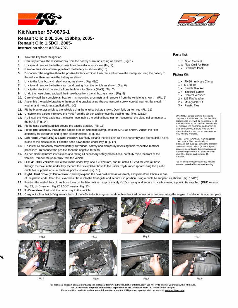
Fig.8
WARNING: Before starting the engine carry out a final fitment check of the K&N performance kit. It will be necessary for all intake systems to be checked periodically for realignment, clearance and tightening of all connections. Failure to follow the above instructions or proper maintenance may void the warranty. FILTER MAINTENANCE: K&N suggests checking the filter periodically for excessive dirt build-up. When the element becomes covered in dirt (or once a year), service it according to the instructions on the Recharger service kit available from your K&N dealer, part number 99- 5003EU. For cleaning instructions please visit our website: www.knfilters.com/cleaning
Parts list: 1 x Filter Element 1 x Flexi Cold Air Hose 1 x Literature Pack Fixing Kit: 1 x 70-90mm Hose Clamp 1 x L Bracket 1 x Saddle Bracket 1 x Tapered Screw 1 x Conical Washer 2 x M6 Flat Washer 2 x M6 Nylock Nut 3 x Plastic Ties
Fig.1 Fig.2 Fig.3
Fig.5
Fig.6
Fig.7
Fig.4
Kit Number 57-0676-1 Renault Clio 2.0L 16v, 138bhp, 2005- Renault Clio 1.5DCi, 2005- Instruction sheet A2054-797-1
1. Take the key from the ignition. 2. Carefully remove the resonator box from the battery surround casing as shown. (Fig. 1) 3. Unclip and remove the battery cover from the vehicle as shown. (Fig. 2) 4. Remove the indicated vent pipe from the battery as shown. (Fig. 3) 5. Disconnect the negative then the positive battery terminal. Unscrew and remove the clamp securing the battery to
the vehicle, then, remove the battery as shown. 6. Unclip the fuse box and relay housing as shown. (Fig. 4&5) 7. Unclip and remove the battery surround casing from the vehicle as shown. (Fig. 6) 8. Unclip the electrical connector from the Mass Air Sensor (MAS). (Fig. 7) 9. Undo the hose clamp and pull the intake hose from the air box as shown. (Fig. 8) 10. Carefully pull the complete air box from its mounting grommets and remove it from the vehicle as shown. (Fig. 9) 11. Assemble the saddle bracket to the mounting bracket using the countersunk screw, conical washer, flat metal
washer and nylock nut supplied. (Fig. 10) 12. Fit the bracket assembly to the vehicle using the original bolt as shown. Don't fully tighten yet! (Fig. 11) 13. Unscrew and carefully remove the MAS from the air box and remove the sealing ring. (Fig. 12&13) 14. Re-install the MAS back into the intake hose, using the original hose clamp. Reconnect the electrical connector to
the MAS. (Fig. 14) 15. Fit the hose clamp supplied around the saddle bracket. (Fig. 15) 16. Fit the filter assembly through the saddle bracket and hose clamp, onto the MAS as shown. Adjust the filter
assembly for clearance and tighten all connections. (Fig. 16) 17. Left Hand Drive (LHD) & 1.5Dci version: Carefully expand the flexi cold air hose assembly and pierce/drill 2 holes
in one of the plastic ends. Feed the hose down to the under tray. (Fig. 17) 18. Re-install all previously removed battery surrounds, battery and clamps by reversing their respective removal
processes. Reconnect the positive then the negative terminal. 19. As per manufacturer's instructions and taking all necessary safety precautions, carefully raise the front of the
vehicle. Remove the under tray from the vehicle. 20. LHD &1.5DCi version: Cut a hole in the under tray, about 70x70 mm, and re-install it. Feed the cold air hose
through the hole in the under tray. Secure the flexi cold air hose to the under tray/bumper spoiler using the plastic cable ties supplied; ensure the hose points forward. (Fig. 18)
21. Right Hand Drive (RHD) version: Carefully expand the flexi cold air hose assembly and pierce/drill 2 holes in one of the plastic ends. Feed the flexi cold air hose into the front grille and secure it in position using a cable tie supplied as shown. (Fig. 19&20)
22. Position the end of the cold air hose towards the filter to finish approximately 4”/10cm away and secure in position using a plastic tie supplied. (RHD version: Fig. 21, LHD version; Fig.22 1.5DCi version Fig. 23)
23. RHD version: Re-install the under tray to the vehicle. 24. Carry out a final height/alignment check of the K&N induction system and double-check all connections before starting the engine. Installation is now complete.
For technical support contact our European technica l team: “[email protected]” We will try to answer your mail within 48 hours. For UK technical enquiries contact R&D department a t 01925-636950, Mon-Thu from 8:30 am to 5 pm.
For other K&N products and / or more information ab out the K&N products please visit our website: www. knfilters.com
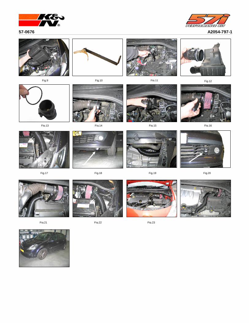
Fig.9
Fig.10
Fig.11 Fig.12
Fig.16
Fig.20
Fig.19
Fig.18
Fig.17
Fig.22 Fig.21
Fig.14 Fig.13 Fig.15
Fig.23
57-0676 A2054-797-1
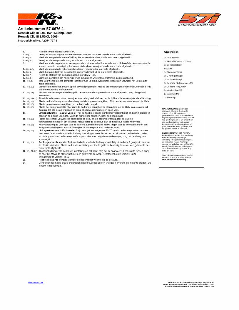
Artikelnummer 57-0676-1 Renault Clio III 2.0L 16v, 138bhp, 2005- Renault Clio III 1.5DCi, 2005- Instructieblad No. A2054-797-1
1. Haal de sleutel uit het contactslot. 2. (Fig.1) Verwijder voorzichtig de resonantiekamer van het omhulsel van de accu zoals afgebeeld. 3. (Fig.2) Maak de aangeduide accu-afdekkap los en verwijder deze uit de auto zoals afgebeeld. 4. (Fig.3) Verwijder de aangeduide slang van de accu zoals afgebeeld. 5. Maak eerst de negatieve en vervolgens de positieve kabel los van de accu. Schroef de klem waarmee de
accu in de auto bevestigd is los en verwijder deze, verwijder nu de accu zoals afgebeeld. 6. (Fig.4+5) Maak de aangeduide zekeringenhouder en relaishouder los zoals afgebeeld. 7. (Fig.6) Maak het omhulsel van de accu los en verwijder het uit de auto zoals afgebeeld. 8. (Fig.7) Neem de stekker van de luchtmassameter (LMM) los. 9. (Fig.8) Maak de slangklem los en verwijder de inlaatslang van het luchtfilterhuis zoals afgebeeld. 10. (Fig.9) Trek voorzichtig de het complete luchtfilterhuis uit zijn bevestigingsrubbers en verwijder het uit de auto
zoals afgebeeld. 11. (Fig.10) Monteer de halfronde beugel op de bevestigingsbeugel met de bijgeleverde platkopschroef, conische ring,
platte metalen ring en borgmoer. 12. (Fig.11) Monteer de samengestelde beugel in de auto met de originele bout zoals afgebeeld. Nog niet geheel
vastzetten! 13. (Fig.12+13) Draai de schroeven los en verwijder voorzichtig de LMM van het luchtfilterhuis en verwijder de afdichtring. 14. (Fig.14) Plaats de LMM terug in de inlaatslang met de originele slangklem. Sluit de stekker weer aan op de LMM. 15. (Fig.15) Plaats de geleverde slangklem om de halfronde beugel. 16. (Fig.16) Plaats het samengestelde filter door de halfronde beugel en de slangklem, op de LMM zoals afgebeeld.
Zorg nu dat alle delen vrijliggen en draai alle bevestigingspunten goed vast. 17. Linksgestuurde + 1.5DCi versie: Trek de flexibele koude-luchtslang voorzichtig uit en boor 2 gaatjes in
een van de plastic uiteinden. Voer de slang naar beneden, naar de bodemplaat. 18. (Fig.17) Plaats alle eerder verwijderde delen rond de accu en de accu weer terug door de diverse
verwijderingsmethoden om te keren. Maak eerst de positieve dan de negatieve kabel weer vast. 19. (Fig.18) Krik voorzichtig de voorzijde van de auto op. Neem hierbij de aanwijzingen van de autofabrikant en alle
veiligheidsmaatregelen in acht. Verwijder de bodemplaat van onder de auto. 20. (Fig.19) Linksgestuurde + 1.5Dci versie: Snijd een gat van ongeveer 70x70 mm in de bodemplaat en monteer
hem weer. Voer nu de koude-luchtslang door dit gat heen. Maak het het einde van de flexibele koude-luchtslang vast aan de bodemplaat/bumperspoiler met de geleverde tie-wraps; zorg dat de slang naar voren wijst.
21. (Fig.20) Rechtsgestuurde versie: Trek de flexibele koude-luchtslang voorzichtig uit en boor 2 gaatjes in een van de plastic uiteinden. Plaats de koude-luchtslang achter de grille en bevestig deze met een geleverde tie-wrap zoals afgebeeld.
22. (Fig.21+22) Richt het uiteinde van de koude-luchtslang op het filter; zorg dat er ongeveer 10 cm ruimte tussen slang en filter zit. Maak de slang vast met een geleverde tie-wrap. (rechtsgestuurde versie: Fig.21 , linksgestuurde versie: Fig.22)
23. Rechtsgestuurde versie: Monteer de bodemplaat weer terug op de auto. 24. Controleer nogmaals of alle onderdelen goed bevestigd zijn en vrij liggen alvorens de motor te starten. De
inbouw is nu voltooid.
Onderdelen 1x Filter-Element 1x Flexibele Koude-Luchtslang
1x Documentatieset
Inbouwkit:-
1x Slangklem 70-90
1x L-vormige Beugel
1x Halfronde Beugel
1x Conische Platkopschroef, M6
1x Conische Ring, Nylon
2x Metalen Ring M6
2x Borgmoer M6
3x Tie-Wrap
WAARSCHUWING: Controleer nogmaals, alvorens de motor te starten, of de K&N-kit correct gemonteerd is. Het is noodzakelijk om regelmatig te controleren of de inlaatkit nog goed vrij ligt en of alle onderdelen nog goed vast zitten. Indien deze instructies niet worden nageleefd of geen onderhoud wordt gepleegd, kan de garantie komen te vervallen. ONDERHOUD VAN HET FILTER: K&N adviseert om het filter regelmatig te inspecteren op overmatige vervuiling. Pleeg onderhoud volgens de instructies van de Recharger service kit, artikelnummer 99-5003EU, verkrijgbaar bij uw K&N verkooppunt, zodra het filter volledig vervuild is (of eens per jaar). Voor informatie over reinigen van het filter kunt u terecht op onze website: www.knfilters.com/cleaning
www.knfilters.com Voor technische ondersteuning in Europa (we proberen binnen 48 uur te antwoorden): "eindhoven.tech@knfi lters.com"
Voor alle informatie over onze producten: www.knfil ters.com
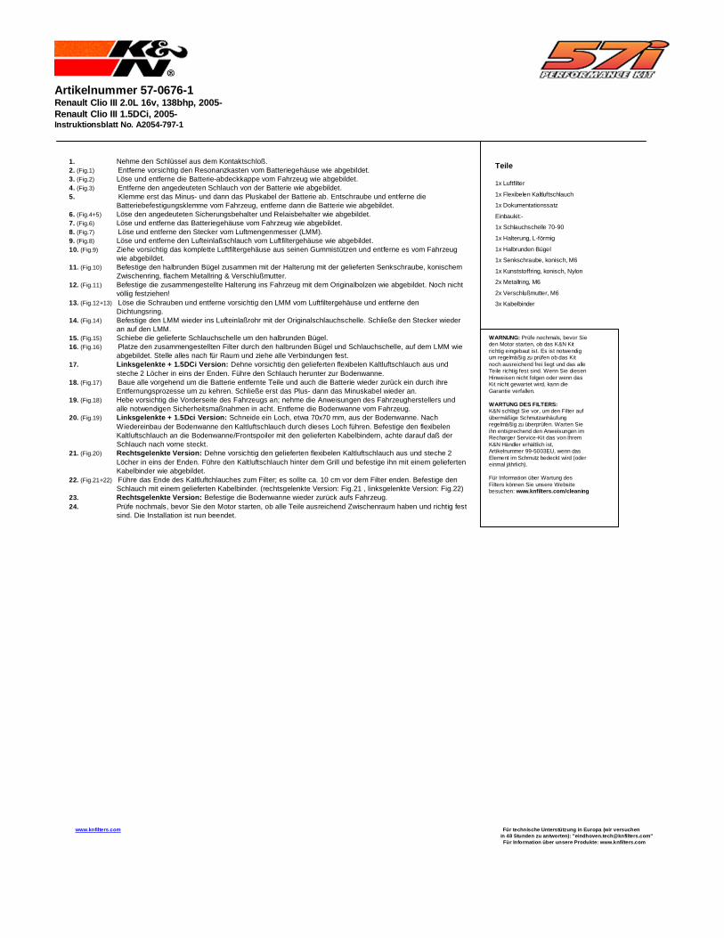
Artikelnummer 57-0676-1 Renault Clio III 2.0L 16v, 138bhp, 2005- Renault Clio III 1.5DCi, 2005- Instruktionsblatt No. A2054-797-1
1. Nehme den Schlüssel aus dem Kontaktschloß. 2. (Fig.1) Entferne vorsichtig den Resonanzkasten vom Batteriegehäuse wie abgebildet. 3. (Fig.2) Löse und entferne die Batterie-abdeckkappe vom Fahrzeug wie abgebildet. 4. (Fig.3) Entferne den angedeuteten Schlauch von der Batterie wie abgebildet. 5. Klemme erst das Minus- und dann das Pluskabel der Batterie ab. Entschraube und entferne die
Batteriebefestigungsklemme vom Fahrzeug, entferne dann die Batterie wie abgebildet. 6. (Fig.4+5) Löse den angedeuteten Sicherungsbehalter und Relaisbehalter wie abgebildet. 7. (Fig.6) Löse und entferne das Batteriegehäuse vom Fahrzeug wie abgebildet. 8. (Fig.7) Löse und entferne den Stecker vom Luftmengenmesser (LMM). 9. (Fig.8) Löse und entferne den Lufteinlaßschlauch vom Luftfiltergehäuse wie abgebildet. 10. (Fig.9) Ziehe vorsichtig das komplette Luftfiltergehäuse aus seinen Gummistützen und entferne es vom Fahrzeug
wie abgebildet. 11. (Fig.10) Befestige den halbrunden Bügel zusammen mit der Halterung mit der gelieferten Senkschraube, konischem
Zwischenring, flachem Metallring & Verschlußmutter. 12. (Fig.11) Befestige die zusammengestellte Halterung ins Fahrzeug mit dem Originalbolzen wie abgebildet. Noch nicht
völlig festziehen! 13. (Fig.12+13) Löse die Schrauben und entferne vorsichtig den LMM vom Luftfiltergehäuse und entferne den
Dichtungsring. 14. (Fig.14) Befestige den LMM wieder ins Lufteinlaßrohr mit der Originalschlauchschelle. Schließe den Stecker wieder
an auf den LMM. 15. (Fig.15) Schiebe die gelieferte Schlauchschelle um den halbrunden Bügel. 16. (Fig.16) Platze den zusammengestellten Filter durch den halbrunden Bügel und Schlauchschelle, auf dem LMM wie
abgebildet. Stelle alles nach für Raum und ziehe alle Verbindungen fest. 17. Linksgelenkte + 1.5DCi Version: Dehne vorsichtig den gelieferten flexibelen Kaltluftschlauch aus und
steche 2 Löcher in eins der Enden. Führe den Schlauch herunter zur Bodenwanne. 18. (Fig.17) Baue alle vorgehend um die Batterie entfernte Teile und auch die Batterie wieder zurück ein durch ihre
Entfernungsprozesse um zu kehren. Schließe erst das Plus- dann das Minuskabel wieder an. 19. (Fig.18) Hebe vorsichtig die Vorderseite des Fahrzeugs an; nehme die Anweisungen des Fahrzeugherstellers und
alle notwendigen Sicherheitsmaßnahmen in acht. Entferne die Bodenwanne vom Fahrzeug. 20. (Fig.19) Linksgelenkte + 1.5Dci Version: Schneide ein Loch, etwa 70x70 mm, aus der Bodenwanne. Nach
Wiedereinbau der Bodenwanne den Kaltluftschlauch durch dieses Loch führen. Befestige den flexibelen Kaltluftschlauch an die Bodenwanne/Frontspoiler mit den gelieferten Kabelbindern, achte darauf daß der Schlauch nach vorne steckt.
21. (Fig.20) Rechtsgelenkte Version: Dehne vorsichtig den gelieferten flexibelen Kaltluftschlauch aus und steche 2 Löcher in eins der Enden. Führe den Kaltluftschlauch hinter dem Grill und befestige ihn mit einem gelieferten Kabelbinder wie abgebildet.
22. (Fig.21+22) Führe das Ende des Kaltluftchlauches zum Filter; es sollte ca. 10 cm vor dem Filter enden. Befestige den Schlauch mit einem gelieferten Kabelbinder. (rechtsgelenkte Version: Fig.21 , linksgelenkte Version: Fig.22)
23. Rechtsgelenkte Version: Befestige die Bodenwanne wieder zurück aufs Fahrzeug. 24. Prüfe nochmals, bevor Sie den Motor starten, ob alle Teile ausreichend Zwischenraum haben und richtig fest
sind. Die Installation ist nun beendet.
Teile 1x Luftfilter
1x Flexibelen Kaltluftschlauch
1x Dokumentationssatz
Einbaukit:-
1x Schlauchschelle 70-90
1x Halterung, L-förmig
1x Halbrunden Bügel
1x Senkschraube, konisch, M6
1x Kunststoffring, konisch, Nylon
2x Metallring, M6
2x Verschlußmutter, M6
3x Kabelbinder
WARNUNG: Prüfe nochmals, bevor Sie den Motor starten, ob das K&N Kit richtig eingebaut ist. Es ist notwendig um regelmäßig zu prüfen ob das Kit noch ausreichend frei liegt und das alle Teile richtig fest sind. Wenn Sie diesen Hinweisen nicht folgen oder wenn das Kit nicht gewartet wird, kann die Garantie verfallen. WARTUNG DES FILTERS: K&N schlägt Sie vor, um den Filter auf übermäßige Schmutzanhäufung regelmäßig zu überprüfen. Warten Sie ihn entsprechend den Anweisungen im Recharger Service-Kit das von Ihrem K&N Händler erhältlich ist, Artikelnummer 99-5003EU, wenn das Element im Schmutz bedeckt wird (oder einmal jährlich). Für Information über Wartung des Filters können Sie unsere Website besuchen: www.knfilters.com/cleaning
www.knfilters.com Für technische Unterst ützung in Europa (wir versuchen in 48 Stunden zu antworten): "eindhoven.tech@knfilt ers.com"
Für Information über unsere Produkte : www.knfilters.com
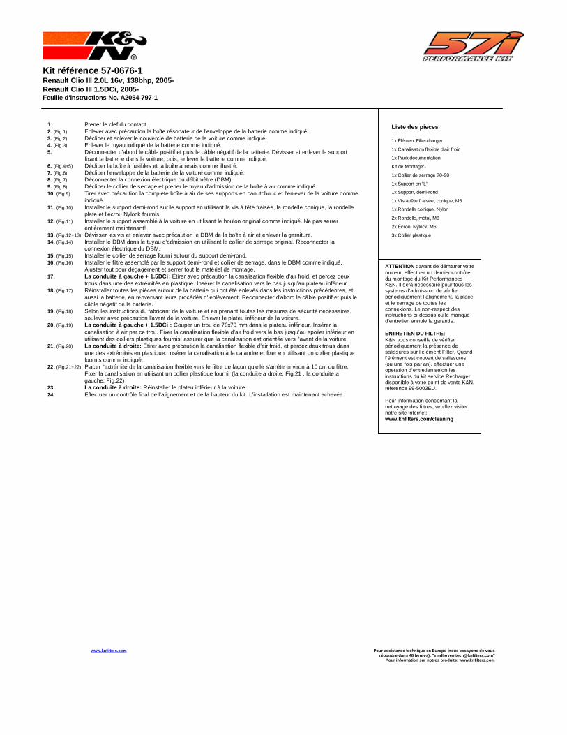
Kit référence 57-0676-1 Renault Clio III 2.0L 16v, 138bhp, 2005- Renault Clio III 1.5DCi, 2005- Feuille d'instructions No. A2054-797-1
1. Prener le clef du contact. 2. (Fig.1) Enlever avec précaution la boîte résonateur de l'enveloppe de la batterie comme indiqué. 3. (Fig.2) Décliper et enlever le couvercle de batterie de la voiture comme indiqué. 4. (Fig.3) Enlever le tuyau indiqué de la batterie comme indiqué. 5. Déconnecter d'abord le câble positif et puis le câble négatif de la batterie. Dévisser et enlever le support
fixant la batterie dans la voiture; puis, enlever la batterie comme indiqué. 6. (Fig.4+5) Décliper la boîte à fusibles et la boîte à relais comme illustré. 7. (Fig.6) Décliper l'enveloppe de la batterie de la voiture comme indiqué. 8. (Fig.7) Déconnecter la connexion électrique du débitmètre (DBM). 9. (Fig.8) Décliper le collier de serrage et prener le tuyau d'admission de la boîte à air comme indiqué. 10. (Fig.9) Tirer avec précaution la complète boîte à air de ses supports en caoutchouc et l'enlever de la voiture comme
indiqué. 11. (Fig.10) Installer le support demi-rond sur le support en utilisant la vis à tête fraisée, la rondelle conique, la rondelle
plate et l’écrou Nylock fournis. 12. (Fig.11) Installer le support assemblé à la voiture en utilisant le boulon original comme indiqué. Ne pas serrer
entièrement maintenant! 13. (Fig.12+13) Dévisser les vis et enlever avec précaution le DBM de la boîte à air et enlever la garniture. 14. (Fig.14) Installer le DBM dans le tuyau d'admission en utilisant le collier de serrage original. Reconnecter la
connexion électrique du DBM. 15. (Fig.15) Installer le collier de serrage fourni autour du support demi-rond. 16. (Fig.16) Installer le filtre assemblé par le support demi-rond et collier de serrage, dans le DBM comme indiqué.
Ajuster tout pour dégagement et serrer tout le matériel de montage. 17. La conduite à gauche + 1.5DCi: Étirer avec précaution la canalisation flexible d’air froid, et percez deux
trous dans une des extrémités en plastique. Insérer la canalisation vers le bas jusqu’au plateau inférieur. 18. (Fig.17) Réinstaller toutes les pièces autour de la batterie qui ont été enlevés dans les instructions précédentes, et
aussi la batterie, en renversant leurs procédés d' enlèvement. Reconnecter d'abord le câble positif et puis le câble négatif de la batterie.
19. (Fig.18) Selon les instructions du fabricant de la voiture et en prenant toutes les mesures de sécurité nécessaires, soulever avec précaution l'avant de la voiture. Enlever le plateu inférieur de la voiture.
20. (Fig.19) La conduite à gauche + 1.5DCi : Couper un trou de 70x70 mm dans le plateau inférieur. Insérer la canalisation à air par ce trou. Fixer la canalisation flexible d’air froid vers le bas jusqu’au spoiler inférieur en utilisant des colliers plastiques fournis; assurer que la canalisation est orientée vers l'avant de la voiture.
21. (Fig.20) La conduite à droite: Étirer avec précaution la canalisation flexible d’air froid, et percez deux trous dans une des extrémités en plastique. Insérer la canalisation à la calandre et fixer en utilisant un collier plastique fournis comme indiqué.
22. (Fig.21+22) Placer l'extrémité de la canalisation flexible vers le filtre de façon qu'elle s'arrête environ à 10 cm du filtre. Fixer la canalisation en utilisant un collier plastique fourni. (la conduite a droite: Fig.21 , la conduite a gauche: Fig.22)
23. La conduite à droite: Réinstaller le plateu inférieur à la voiture. 24. Effectuer un contrôle final de l’alignement et de la hauteur du kit. L’installation est maintenant achevée.
Liste des pieces 1x Élément Filtercharger
1x Canalisation flexible d'air froid
1x Pack documentation
Kit de Montage:-
1x Collier de serrage 70-90
1x Support en "L"
1x Support, demi-rond
1x Vis à tête fraisée, conique, M6
1x Rondelle conique, Nylon
2x Rondelle, métal, M6
2x Écrou, Nylock, M6
3x Collier plastique
ATTENTION : avant de démarrer votre moteur, effectuer un dernier contrôle du montage du Kit Performances K&N. Il sera nécessaire pour tous les systems d’admission de vérifier périodiquement l’alignement, la place et le serrage de toutes les connexions. Le non-respect des instructions ci-dessus ou le manque d’entretien annule la garantie. ENTRETIEN DU FILTRE: K&N vous conseille de vérifier périodiquement la présence de salissures sur l’élément Filter. Quand l’élément est couvert de salissures (ou une fois par an), effectuer une operation d’entretien selon les instructions du kit service Recharger disponible à votre point de vente K&N, référence 99-5003EU. Pour information concernant la nettoyage des filtres, veuillez visiter notre site internet: www.knfilters.com/cleaning
www.knfilters.com Pour assistance technique en Eu rope (nous essayons de vous répondre dans 48 heures): "eindhoven.tech@knfilters .com"
Pour information sur notres produits: www.knfilters .com