Embed Size (px)
Citation preview
Issue Date: July 2017 © 2020 Kiwa Ltd. Page 1 of 15
Kiwa Ltd.Unit 5 Prime Park WayPrime Enterprise ParkDerbyDE1 3QBT: +44 (0)1332 383333W: www.kiwa.co.uk/bda
BAF-18-040-S-A-UKBDA Agrément®
Beamshield Top Sheet/UFH andBeamshield Plus Top Sheet/UFH
Flooring Insulation Systems
Springvale EPS Ltd.Dinting Vale
GlossopDerbyshireSK13 6LG
T: +44 (0)845 769 7452E: [email protected]
W: www.springvale.com
SCOPE OF AGRÉMENT
This Agrément relates to Beamshield Top Sheet/UFH and Beamshield Plus Top Sheet/UFH flooring insulation systems (hereinafter the ‘Systems’). The Systemsare for use as thermal insulation in suspended ground floors in domestic, residential and commercial buildings.
SYSTEM DESCRIPTION
The Systems comprise Beamshield Infill, Beamshield Plus, Beamshield Top Sheet and Beamshield Variable Width Board (hereinafter ‘Beamshield VWB’)expanded polystyrene (hereinafter ‘EPS’) units. The EPS units are available in standard performance (white) or Platinum high performance (grey) versions andare manufactured in accordance with BS EN 15037-4 and BS EN 13163 as applicable. The Systems are used in conjunction with structural concrete toppings,pre-stressed concrete beams and masonry closure and coursing blocks (manufactured by others) in suspended concrete ground floors over a sub-floor void.
SYSTEM ILLUSTRATION
THIRD-PARTY ACCEPTANCE
NHBC - For detailed information see section 3.3 (Third-Party Acceptance).
STATEMENT
It is the opinion of Kiwa Ltd., that the Systems are fit for their intended use, provided they are specified, installed and used in accordance with this Agrément.
Chris Vurley, CEng Mark Crowther, M.A. (Oxon)
Technical Manager, Building Products Kiwa Ltd. Technical Director

Issue Date: July 2017 © 2020 Kiwa Ltd. Page 2 of 15
SUMMARY OF AGRÉMENT
This document provides independent information to specifiers, building control personnel, contractors, installers and other construction industry professionalsconsidering the fitness for the intended use of the Systems. This Agrément covers the following: Conditions of use; Factory Production Control, Quality Management System and the Annual Verification procedure; Points of attention for the Specifier and examples of details; Installation; Independently assessed System characteristics and other information; Compliance with national Building Regulations, other regulatory requirements and Third-Party Acceptance, as appropriate; Sources.
MAJOR POINTS OF ASSESSMENT
Thermal performance - the EPS components used in correctly designed and installed Systems can enable a floor to meet the requirements of the nationalBuilding Regulations in respect of U-value performance (see sections 2.1.9 and 2.1.10).
Condensation and water (vapour) infiltration risk - the EPS components used in correctly designed and installed Systems can contribute to suitablycontrolling the risk of interstitial and surface condensation (see section 2.1.11).
Structural performance - correctly designed and installed Systems will have sufficient strength and rigidity to sustain and transmit both dead and imposed floorloads (see section 2.1.12).
Durability - the EPS components are chemically stable, rot-proof and durable and have a design life equivalent to that of the building in which they areincorporated (see section 2.1.13).
CE marking - the product manufacturers have taken responsibility for CE marking of the products used in the Systems in accordance with all relevantharmonised European Product Standards. An asterisk (*) appearing in this Agrément indicates that data shown is given in the relevant product manufacturer’sDeclaration of Performance (DoP) (see section 2.1.14).
CONTENTS
Chapter 1 - General considerations1.1 - Conditions of use1.2 - Factory Production Control (FPC) and Quality Management System (QMS)1.3 - Annual verification procedure - continuous surveillanceChapter 2 - Technical assessment2.1 - Points of attention to the Specifier2.2 - Examples of details2.3 - Installation2.4 - Independently assessed System characteristics2.5 - System components and ancillary items2.6 - Typical installation examplesChapter 3 - CDM, national Building Regulations and Third-Party Acceptance3.1 - The Construction (Design and Management) Regulations 2015 and The Construction (Design and Management) Regulations (Northern Ireland) 20163.2 - The national Building Regulations3.3 - Third-Party AcceptanceChapter 4 - SourcesChapter 5 - Amendment history

Issue Date: July 2017 © 2020 Kiwa Ltd. Page 3 of 15
CHAPTER 1 - GENERAL CONSIDERATIONS
1.1 - CONDITIONS OF USE
1.1.1 Design considerationsSee section 2.1.
1.1.2 ApplicationThe assessment of the Systems relates to their use in accordance with this Agrément and the Agrément holder’s requirements.
1.1.3 AssessmentKiwa Ltd. has assessed the Systems in combination with their relevant DoPs, test reports, technical literature and factory and site visits. Also, NHBC Standardshave been taken into consideration. Factory Production Control has been assessed.
1.1.4 Installation supervisionThe quality of installation and workmanship must be controlled by a competent person who must be an employee of the installation company.
The Systems must be installed strictly in accordance with the instructions of the Agrément holder and the requirements of this Agrément.
1.1.5 Geographical scopeThe validity of this document is limited to England, Wales, Scotland and Northern Ireland, with due regard to Chapter 3 of this Agrément (CDM, national BuildingRegulations and Third-Party Acceptance).
1.1.6 ValidityThe purpose of this BDA Agrément® is to provide for well-founded confidence to apply the Systems within the Scope described. The validity of this Agrément isthree years after the issue date, and as published on www.kiwa.co.uk/bda.
1.2 - FACTORY PRODUCTION CONTROL (FPC) AND QUALITY MANAGEMENT SYSTEM (QMS)
Kiwa Ltd. has determined that the Agrément holder fulfils all obligations in relation to this Agrément, in respect of the Systems.
The initial FPC audit demonstrated that the Agrément holder has a satisfactory Quality Management System (QMS) and is committed to continuously improvingtheir FPC operations.
Document control and record keeping procedures were deemed satisfactory.
A detailed Production Quality Specification (PQS) has been compiled to ensure traceability and compliance under the terms of this Agrément.
1.3 - ANNUAL VERIFICATION PROCEDURE - CONTINUOUS SURVEILLANCE
To demonstrate that the FPC is in conformity with the requirements of the technical specification described in this Agrément, the continuous surveillance,assessment and approval of the FPC will be done at a frequency of not less than once per year by Kiwa Ltd.

Issue Date: July 2017 © 2020 Kiwa Ltd. Page 4 of 15
CHAPTER 2 - TECHNICAL ASSESSMENT
This Agrément does not constitute a design guide for the Systems. It is intended as an assessment of fitness for purpose only.
2.1 - POINTS OF ATTENTION TO THE SPECIFIER
2.1.1 Design responsibilityA Specifier may undertake a project specific design in which case it is recommended that the Specifier co-operates closely with the Agrément holder; theSpecifier is responsible for the final project specific design.
2.1.2 Applied building physics (heat, air, moisture)The physical behaviour of the building incorporating the Systems shall be verified as suitable by a competent specialist, who can be either a qualified employeeof the Agrément holder or a qualified consultant. The Specialist will check the physical behaviour of the building design and if necessary, can offer advice inrespect of improvements to achieve the final specification. It is recommended that the Specialist co-operates closely with the Agrément holder.
2.1.3 General design considerationsA project specific design will be required and must give due consideration to the composite of the EPS elements (see section 2.1.12.2), the pre-stressedconcrete beams (see section 2.1.12.3) and the structural concrete toppings (see section 2.1.12.4).
2.1.4 Project specific design considerationsNo pre-installation survey is required for the installation of the Systems - see section 2.3.3.
2.1.5 Permitted applicationsOnly applications designed according to the specifications as given in this Agrément are allowed under this Agrément, in each case the Specifier will have to co-operate closely with the Agrément holder.
2.1.6 Installer competence levelThe Systems must be installed strictly in accordance with the instructions of the Agrément holder and the requirements of this Agrément.
Installation can be undertaken by competent persons experienced in this sort of work.
2.1.7 Delivery, storage and site handlingThe Systems are delivered to site in suitable packaging, that bear the System name, the Agrément holder’s name, the CE mark and the BDA Agrément® logoincorporating the number of this Agrément.
Store the System components in accordance with the Agrément holder’s requirements. Particular care must be taken to: stack off the ground (to avoid contamination); protect from damage caused by impact or handling; avoid exposure to direct sunlight and high or low temperatures for extended periods of time; avoid contact with organic solvents; store away from possible ignition sources.
2.1.8 Maintenance and repairOnce installed, the Systems do not require maintenance.
Performance factors in relation to the Major Points of Assessment
2.1.9 Thermal performanceFor the purpose of U-value calculations and to determine if the requirements of the national Building Regulations are met, the thermal resistances of the projectspecific design shall be calculated according to BR 443 and BS EN ISO 10211. The recommendations of the Thermal Bridging Guide should also be observed.
The Agrément holder can provide a service for 2D and 3D calculations for numerically modelled EPS beam and block configurations, complying toBS EN ISO 13370, BS EN ISO 10211 and BR497.
The requirement for limiting heat loss through the building fabric, including the effect of thermal bridging can be satisfied if the U-values of the building elementsdo not exceed the maximum values in the relevant Elemental Methods given in the national Building Regulations. Further information with respect to nationalBuilding Regulations is given in Chapter 3 of this Agrément.
2.1.10 Junction linear thermal transmittance (ψ) valuesThe Agrément holder provides a design service to maximise the benefit of the Systems in improved ψ-values including external walls (perpendicular andparallel), party walls, thresholds and temperature factors. Care must be taken in the overall design and construction of junctions with other elements to minimisethermal bridges and air infiltration. Guidance on linear thermal transmittance, heat flows and surface temperatures can be found in the documents supportingthe national Building Regulations and BS EN ISO 10211, BRE Information Paper IP 1/06, BRE Report 262, BRE Report 497 and PAS 2030 - Building FabricMeasures (BFM). Modelling can be undertaken according to BR 497. Consult the Agrément holder for further details.
Default ψ-values are given in SAP 2012.
2.1.11 Condensation riskGround floors incorporating correctly designed and installed Systems can limit the risk of interstitial and surface condensation when designed in accordance withBS 5250. A condensation risk analysis must be completed by the Specifier at project specific design stage.

Issue Date: July 2017 © 2020 Kiwa Ltd. Page 5 of 15
In order to minimise any risk of interstitial condensation, there must always be an underfloor void of at least 150 mm high beneath the lowest point of the floorconstruction, which incorporates ventilation openings in opposing external walls to facilitate through-ventilation. Any pipes used to carry ventilating air should bea minimum of 100 mm in diameter and ventilation openings should be a minimum of 1500 mm2.m-1 of external wall run or 500 mm2.m-2 of the floor area,depending which is the greatest.
When designed and installed in accordance with this Agrément the Systems will contribute to a convection-free envelope of high vapour resistance.
Wall insulation should extend to at least 150 mm beyond the bottom of the beam in order to minimise any risk of interstitial condensation at junctions of floorsand external walls.
To minimise the risk of condensation at service penetrations, care must be taken to minimise gaps in the insulation layer, for example by filling with expandingfoam insulation.
2.1.12 Structural performance
2.1.12.1 GeneralA qualified structural engineer must ensure that the Systems are suitable for their intended use, including in the temporary works phase prior to the curing of thestructural topping.
Where a partition wall (defined as a blockwork or stud wall) of ≤ 1 kN·m-1 is required, this can be placed in any orientation across the floor area, subject to theStructural Engineer’s project specific design.
Partition walls running parallel to beams must be installed directly above, or within a maximum distance from the supporting beams specified by the StructuralEngineer. The Structural Engineer should be consulted to ensure the structural topping and beam/s have suitable strength and stiffness to transfer the partitionwall loading to supporting structural elements.
Partition walls perpendicular to beams must be adequately supported.
It is important that Beamshield Top Sheets are not installed with joints within any zone of structural loading or influence. These include (but are not limited to)directly over and parallel to the precast concrete beams, nor within 375 mm of the centreline of a partition spanning perpendicular to the beams.
2.1.12.2 Beamshield EPS units (Beamshield Plus and Beamshield Infill), Beamshield Top Sheets and Beamshield VWBThe Beamshield Plus and Beamshield Infill units in conjunction with Beamshield Top Sheets and Beamshield VWB provide a formwork to the structural concretetopping. Only the Beamshield Top Sheets make a further contribution to the long-term structural performance of the floor in the form of load spreading, once thestructural concrete topping has been placed and obtained its’ full design strength.
Installation of the Beamshield EPS units requires free movement of beams, this will also assist with fitting multiple beam units and thicker units.
Placing beams in contact with parallel walls must be avoided as this creates a cold bridge.
When using Beamshield Plus units it is good practice to begin each bay with a Beamshield EPS starter unit and proceed installing the units in the direction ofthe toe and continue to the opposite wall. Change of direction must be avoided as this could lead to gaps in the insulation envelope.
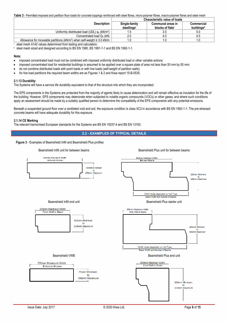
The structural concrete topping over the Beamshield EPS starter and end units shall project no greater than 300 mm and must be designed as a cantileveredslab. Beamshield EPS end units can be cut from full or half units, ensuring that this is done accurately and squarely so they fit closely to the inner leaf of thewall. The Beamshield VWB shall be no greater 350 mm wide.
To reduce the risk of accidental penetration of the System components during the construction phase, spacers for supporting mesh reinforcement should belocated on spreader plates over the Beamshield Top Sheets.
2.1.12.3 Precast concrete beamsThe structural pre-stressed concrete beams act to transfer load to the supporting primary structure.
The project specific pre-stressed concrete beam configuration must be designed in accordance with BS EN 1992-1-1 by the Structural Engineer to ensure thatthe beams are adequate to resist the applied loading. It should be ensured that the natural frequency of the beam exceeds 4 Hz and that the response factor ofthe floor to footfall vibration is in line with design guidance and industry best practice. Due design consideration should be given to vibration from externalsources or rhythmic activity.
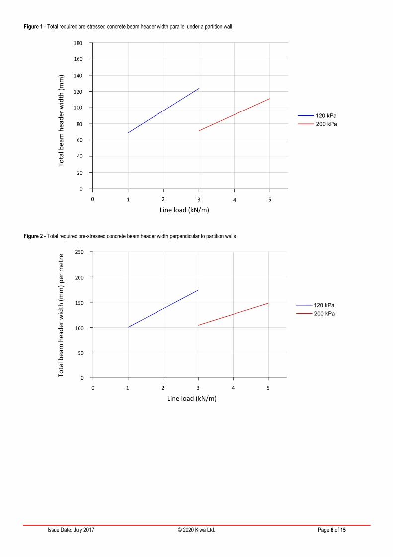
For the total required pre-stressed concrete beam header width parallel and perpendicular to the partition wall for the top sheets defined in Table 6, see Figures1 and 2 respectively.
The pre-stressed concrete beams must be CE marked, designed and manufactured to BS EN 15037-1.
Due consideration should be given to BS EN 1992-1-1 when considering the serviceability deflection limit of pre-stressed concrete beams used in the Systems.
Calculations must be made in line with the guidance and requirements of BS EN 1992-1-1 to determine the maximum effective spans of pre-stressed concretebeams (making the assumption that the pre-stressed concrete beams are simply supporting and self-bearing). The minimum bearing width to support the pre-stressed concrete beam should be 90 mm as defined in BS 8103-1.
Where two or more concrete beams are placed side by side (such as under load-bearing walls), the spaces between the beam webs should be filled with aminimum strength class concrete of C25/30.
Issue Date: July 2017 © 2020 Kiwa Ltd. Page 6 of 15
Figure 1 - Total required pre-stressed concrete beam header width parallel under a partition wall
Figure 2 - Total required pre-stressed concrete beam header width perpendicular to partition walls
0 1 2 3 4
0
20
40
60
80
100
120
140
160
180
Tota
l bea
m h
eade
r wid
th (m
m)
Line load (kN/m)5
0
50
100
150
200
0 1 2 3 4
250
Tota
l bea
m h
eade
r wid
th (m
m) p
er m
etre
Line load (kN/m)5
Issue Date: July 2017 © 2020 Kiwa Ltd. Page 7 of 15
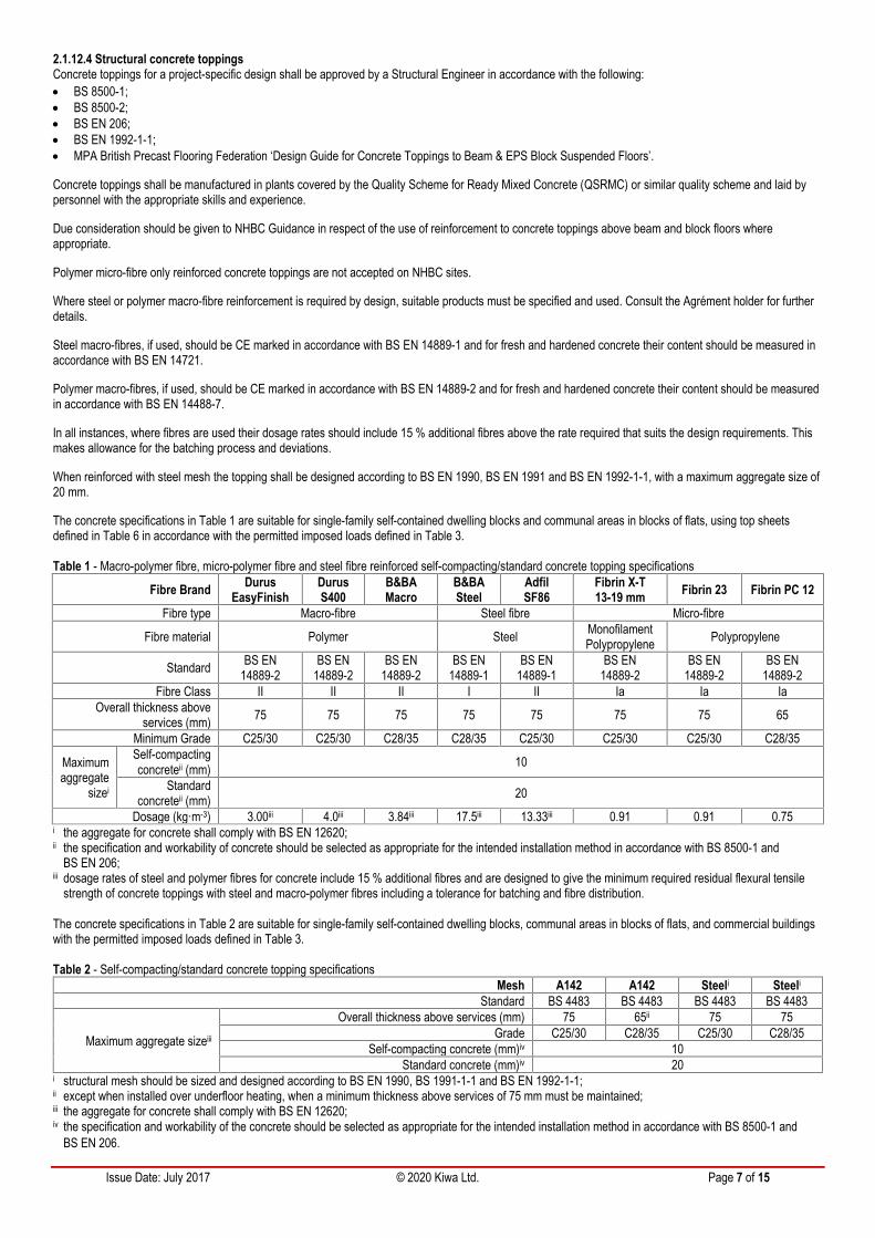
2.1.12.4 Structural concrete toppingsConcrete toppings for a project-specific design shall be approved by a Structural Engineer in accordance with the following: BS 8500-1; BS 8500-2; BS EN 206; BS EN 1992-1-1; MPA British Precast Flooring Federation ‘Design Guide for Concrete Toppings to Beam & EPS Block Suspended Floors’.
Concrete toppings shall be manufactured in plants covered by the Quality Scheme for Ready Mixed Concrete (QSRMC) or similar quality scheme and laid bypersonnel with the appropriate skills and experience.
Due consideration should be given to NHBC Guidance in respect of the use of reinforcement to concrete toppings above beam and block floors whereappropriate.
Polymer micro-fibre only reinforced concrete toppings are not accepted on NHBC sites.
Where steel or polymer macro-fibre reinforcement is required by design, suitable products must be specified and used. Consult the Agrément holder for furtherdetails.
Steel macro-fibres, if used, should be CE marked in accordance with BS EN 14889-1 and for fresh and hardened concrete their content should be measured inaccordance with BS EN 14721.
Polymer macro-fibres, if used, should be CE marked in accordance with BS EN 14889-2 and for fresh and hardened concrete their content should be measuredin accordance with BS EN 14488-7.
In all instances, where fibres are used their dosage rates should include 15 % additional fibres above the rate required that suits the design requirements. Thismakes allowance for the batching process and deviations.
When reinforced with steel mesh the topping shall be designed according to BS EN 1990, BS EN 1991 and BS EN 1992-1-1, with a maximum aggregate size of20 mm.
The concrete specifications in Table 1 are suitable for single-family self-contained dwelling blocks and communal areas in blocks of flats, using top sheetsdefined in Table 6 in accordance with the permitted imposed loads defined in Table 3.
Table 1 - Macro-polymer fibre, micro-polymer fibre and steel fibre reinforced self-compacting/standard concrete topping specifications
Fibre Brand DurusEasyFinish
DurusS400
B&BAMacro
B&BASteel
AdfilSF86
Fibrin X-T13-19 mm Fibrin 23 Fibrin PC 12
Fibre type Macro-fibre Steel fibre Micro-fibre
Fibre material Polymer Steel MonofilamentPolypropylene Polypropylene
Standard BS EN14889-2
BS EN14889-2
BS EN14889-2
BS EN14889-1
BS EN14889-1
BS EN14889-2
BS EN14889-2
BS EN14889-2
Fibre Class II II II I II Ia Ia IaOverall thickness above
services (mm) 75 75 75 75 75 75 75 65
Minimum Grade C25/30 C25/30 C28/35 C28/35 C25/30 C25/30 C25/30 C28/35
Maximumaggregate
sizei
Self-compactingconcreteii (mm) 10
Standardconcreteii (mm) 20
Dosage (kg·m-3) 3.00iii 4.0iii 3.84iii 17.5iii 13.33iii 0.91 0.91 0.75i the aggregate for concrete shall comply with BS EN 12620;ii the specification and workability of concrete should be selected as appropriate for the intended installation method in accordance with BS 8500-1 and
BS EN 206;iii dosage rates of steel and polymer fibres for concrete include 15 % additional fibres and are designed to give the minimum required residual flexural tensile
strength of concrete toppings with steel and macro-polymer fibres including a tolerance for batching and fibre distribution.
The concrete specifications in Table 2 are suitable for single-family self-contained dwelling blocks, communal areas in blocks of flats, and commercial buildingswith the permitted imposed loads defined in Table 3.
Table 2 - Self-compacting/standard concrete topping specificationsMesh A142 A142 Steeli Steeli
Standard BS 4483 BS 4483 BS 4483 BS 4483
Maximum aggregate sizeiii
Overall thickness above services (mm) 75 65ii 75 75Grade C25/30 C28/35 C25/30 C28/35
Self-compacting concrete (mm)iv 10Standard concrete (mm)iv 20
i structural mesh should be sized and designed according to BS EN 1990, BS 1991-1-1 and BS EN 1992-1-1;ii except when installed over underfloor heating, when a minimum thickness above services of 75 mm must be maintained;iii the aggregate for concrete shall comply with BS EN 12620;iv the specification and workability of the concrete should be selected as appropriate for the intended installation method in accordance with BS 8500-1 and
BS EN 206.
Issue Date: July 2017 © 2020 Kiwa Ltd. Page 8 of 15
Table 3 - Permitted imposed and partition floor loads for concrete toppings reinforced with steel fibres, micro-polymer fibres, macro-polymer fibres and steel mesh
DescriptionCharacteristic value of loads
Single-familydwellingsi
Communal areas inblocks of flatsi
Commercialbuildingsii
Uniformly distributed load (UDL) qk (kN/m2) 1.5 3.0 5.0Concentrated load Qk (kN) 2.0 4.0 4.5
Allowance for moveable partitions (kN/m2) when self-weight ≤ 3.0 kN/m 1.0 1.0 1.0i steel mesh A142 values determined from testing and calculation;ii steel mesh sized and designed according to BS EN 1990, BS 1991-1-1 and BS EN 1992-1-1.
Note: imposed concentrated load must not be combined with imposed uniformly distributed load or other variable actions; imposed concentrated load for residential buildings is assumed to be applied over a square plate of area not less than 50 mm by 50 mm; do not combine distributed loads with point loads or with line loads (self-weight of partition walls); for line load partitions the required beam widths are as Figures 1 & 2 and Kiwa report 15-B-0535.
2.1.13 DurabilityThe Systems will have a service life durability equivalent to that of the structure into which they are incorporated.
The EPS components in the Systems are protected from the majority of agents likely to cause deterioration and will remain effective as insulation for the life ofthe building. However, EPS components may deteriorate when subjected to volatile organic compounds (VOCs) or other gases, and where such conditionsapply an assessment should be made by a suitably qualified person to determine the compatibility of the EPS components with any potential emissions.
Beneath a suspended ground floor over a ventilated void and soil, the exposure condition is class XC3 in accordance with BS EN 1992-1-1. The pre-stressedconcrete beams will have adequate durability for this exposure.
2.1.14 CE MarkingThe relevant harmonised European standards for the Systems are BS EN 15037-4 and BS EN 13163.
2.2 - EXAMPLES OF TYPICAL DETAILS
Figure 3 - Examples of Beamshield Infill and Beamshield Plus profiles
Beamshield Infill unit for between beams Beamshield Plus unit for between beams
Beamshield Infill end unit Beamshield Plus starter unit
Beamshield VWB Beamshield Plus end unit
Issue Date: July 2017 © 2020 Kiwa Ltd. Page 9 of 15
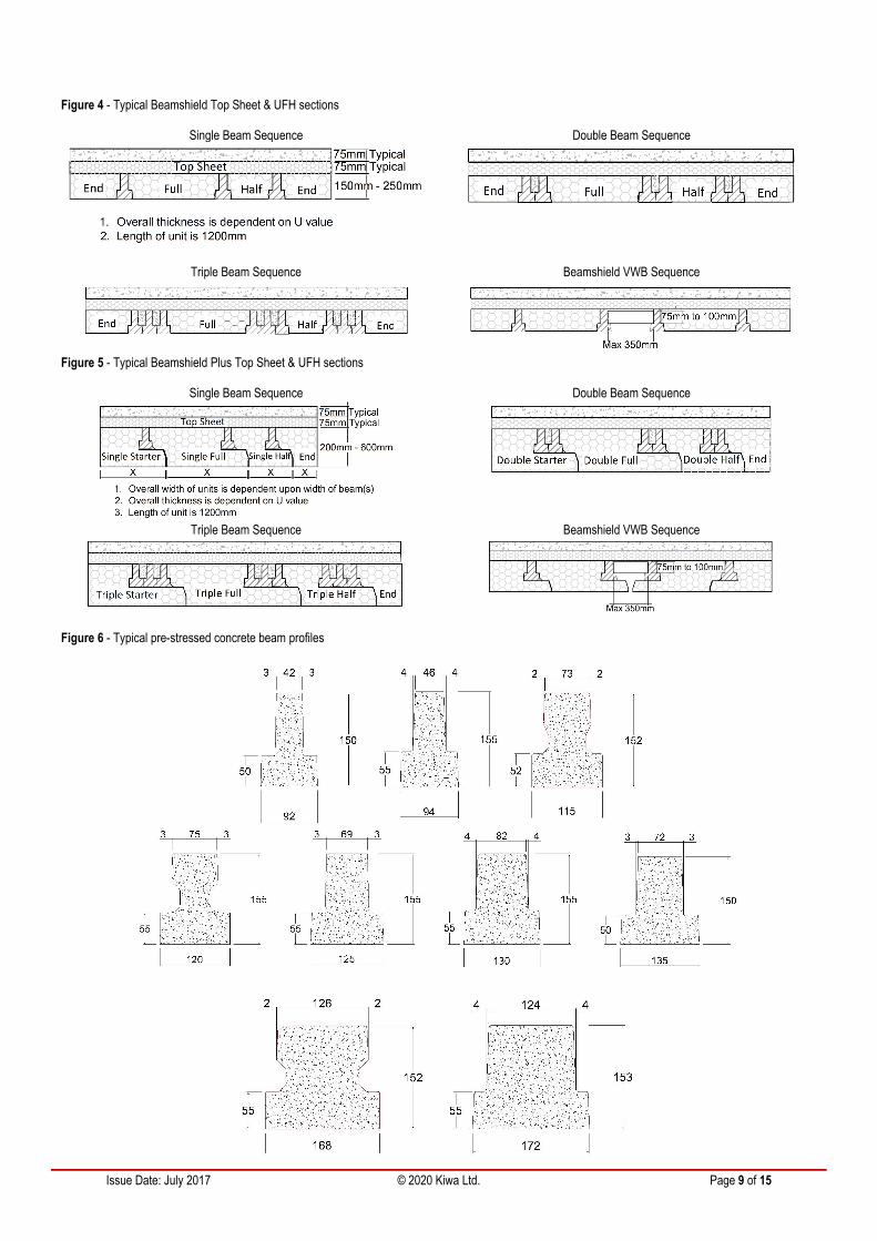
Figure 4 - Typical Beamshield Top Sheet & UFH sections
Single Beam Sequence Double Beam Sequence
Triple Beam Sequence Beamshield VWB Sequence
Figure 5 - Typical Beamshield Plus Top Sheet & UFH sections
Single Beam Sequence Double Beam Sequence
Triple Beam Sequence Beamshield VWB Sequence
Figure 6 - Typical pre-stressed concrete beam profiles
Issue Date: July 2017 © 2020 Kiwa Ltd. Page 10 of 15
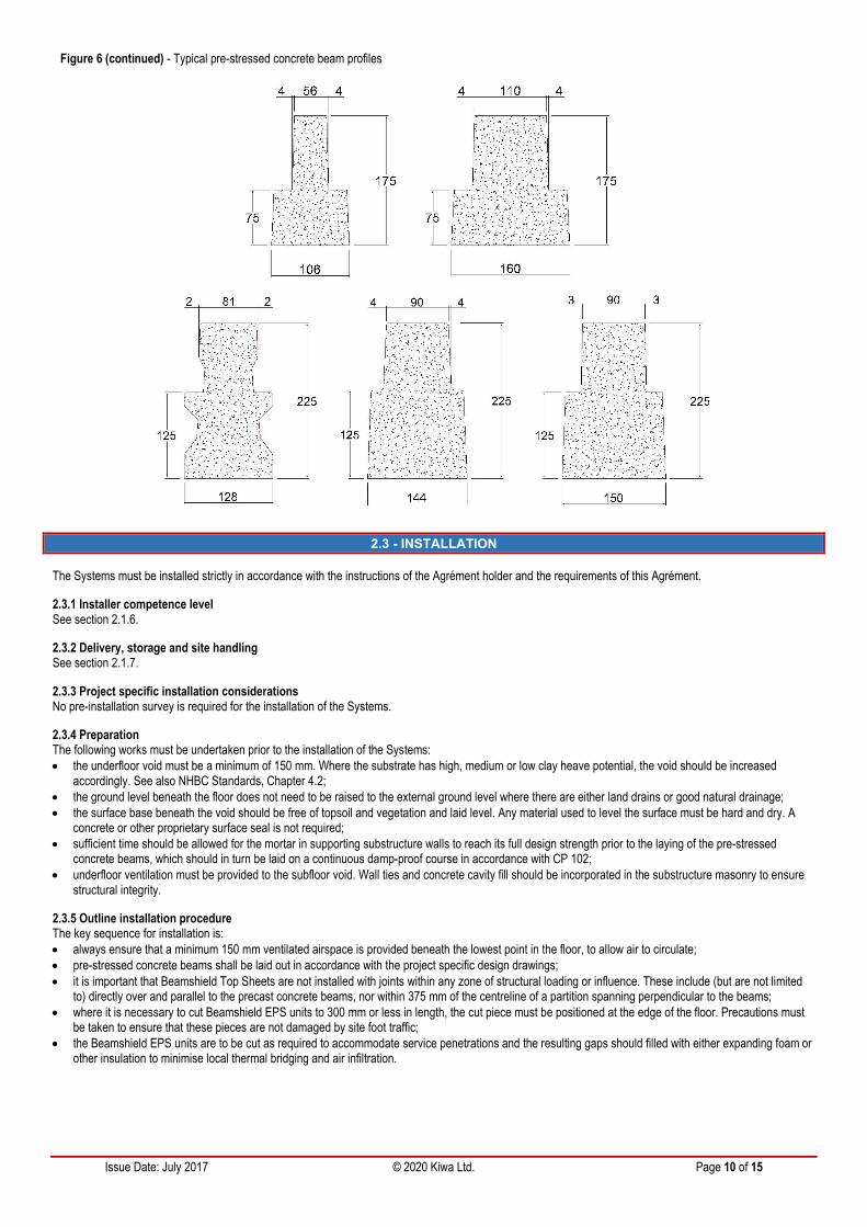
Figure 6 (continued) - Typical pre-stressed concrete beam profiles
2.3 - INSTALLATION
The Systems must be installed strictly in accordance with the instructions of the Agrément holder and the requirements of this Agrément.
2.3.1 Installer competence levelSee section 2.1.6.
2.3.2 Delivery, storage and site handlingSee section 2.1.7.
2.3.3 Project specific installation considerationsNo pre-installation survey is required for the installation of the Systems.
2.3.4 PreparationThe following works must be undertaken prior to the installation of the Systems: the underfloor void must be a minimum of 150 mm. Where the substrate has high, medium or low clay heave potential, the void should be increased
accordingly. See also NHBC Standards, Chapter 4.2; the ground level beneath the floor does not need to be raised to the external ground level where there are either land drains or good natural drainage; the surface base beneath the void should be free of topsoil and vegetation and laid level. Any material used to level the surface must be hard and dry. A
concrete or other proprietary surface seal is not required; sufficient time should be allowed for the mortar in supporting substructure walls to reach its full design strength prior to the laying of the pre-stressed
concrete beams, which should in turn be laid on a continuous damp-proof course in accordance with CP 102; underfloor ventilation must be provided to the subfloor void. Wall ties and concrete cavity fill should be incorporated in the substructure masonry to ensure
structural integrity.
2.3.5 Outline installation procedureThe key sequence for installation is: always ensure that a minimum 150 mm ventilated airspace is provided beneath the lowest point in the floor, to allow air to circulate; pre-stressed concrete beams shall be laid out in accordance with the project specific design drawings; it is important that Beamshield Top Sheets are not installed with joints within any zone of structural loading or influence. These include (but are not limited
to) directly over and parallel to the precast concrete beams, nor within 375 mm of the centreline of a partition spanning perpendicular to the beams; where it is necessary to cut Beamshield EPS units to 300 mm or less in length, the cut piece must be positioned at the edge of the floor. Precautions must
be taken to ensure that these pieces are not damaged by site foot traffic; the Beamshield EPS units are to be cut as required to accommodate service penetrations and the resulting gaps should filled with either expanding foam or
other insulation to minimise local thermal bridging and air infiltration.
Issue Date: July 2017 © 2020 Kiwa Ltd. Page 11 of 15
Beamshield Infill unitsThe following applies with specific regard to Beamshield Infill units: all Beamshield Infill units shall be installed from above; it is good practice to use the appropriate Beamshield Infill unit to measure the distances between beams; Beamshield Infill end units can be cut as required to start and end the sequence.
Beamshield Plus unitsThe following applies with specific regard to Beamshield Plus units: Beamshield Plus starter units are to be attached to the first beam and then positioned tightly against the wall; it is good practice to start each floor with a Beamshield Plus starter unit and proceed in the direction of the toe to the opposite wall; it must be ensured that the correct Beamshield Plus units are used with single beams and multiple beams. The vertical gap between the Beamshield Plus
unit toe and the adjacent Beamshield Plus unit must not exceed 6 mm in order to prevent cold air passing through gaps in the Beamshield Plus units andreducing the thermal performance of the System.
2.3.6 FinishingThe following finishing is required upon completion of the installation: the Agrément holder can supply profiled Beamshield EPS end units for the project specific design. Alternatively, full or half Beamshield EPS units can be
cut down on site to the required size ensuring that they are no more than 300 mm wide at the top; a gas barrier membrane can be installed where specified and laid in accordance with the membrane manufacturer’s requirements; the Beamshield Top Sheet is laid over the precast concrete beams and Beamshield EPS units and cut with a handsaw to accommodate service
penetrations and part sheet widths where necessary. Small offcuts can be used to seal around service penetrations.
Note: At this stage the floor is not suitable to be loaded or to support wheeled traffic/scaffold etc.
Beamshield UFH and Beamshield Plus UFHIf specified, underfloor heating pipes can be installed. These can be secured to the Beamshield Top Sheet using standard pipe clips. A minimum 75 mmthickness of structural concrete topping above the pipes must be maintained.
Structural concrete toppingPrior to the concrete pour, Perimeter Strips (30 mm thick white EPS or 25 mm thick Platinum EPS) must be installed against the exposed inner leaf of theperimeter wall.
The specified structural concrete topping shall be poured carefully and not dropped from a height greater than 500 mm, ensuring that heaping is kept to a heightof not greater than 300 mm.
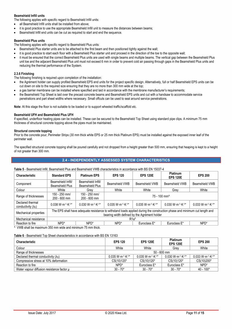
2.4 - INDEPENDENTLY ASSESSED SYSTEM CHARACTERISTICS
Table 5 - Beamshield Infill, Beamshield Plus and Beamshield VWB characteristics in accordance with BS EN 15037-4
Characteristic Standard EPS Platinum EPS EPS 120 EPS 120E PlatinumEPS 120E EPS 200
Component Beamshield Infill/Beamshield Plus
Beamshield Infill/Beamshield Plus Beamshield VWB Beamshield VWB Beamshield VWB Beamshield VWB
Colour White Grey White White Grey White
Range of thicknesses 150 - 250 mm/200 - 600 mm
150 - 250 mm/200 - 600 mm 75 - 100 mm^
Declared thermalconductivity (λD) 0.038 W·m-1·K-1* 0.030 W·m-1·K-1* 0.035 W·m-1·K-1* 0.035 W·m-1·K-1* 0.030 W·m-1·K-1* 0.033 W·m-1·K-1*
Mechanical properties The EPS shall have adequate resistance to withstand loads applied during the construction phase and minimum cut length andbearing width defined by the Agrément holder
Mechanical resistance R1a*Reaction to fire NPD* NPD* NPD* Euroclass E* Euroclass E* NPD*
^ VWB shall be maximum 350 mm wide and minimum 75 mm thick.
Table 6 - Beamshield Top Sheet characteristics in accordance with BS EN 13163
Characteristic EPS 120 EPS 120E PlatinumEPS 120E EPS 200
Colour White White Grey WhiteRange of thicknesses 50 - 600 mmDeclared thermal conductivity (λD) 0.035 W·m-1·K-1* 0.035 W·m-1·K-1* 0.030 W·m-1·K-1* 0.033 W·m-1·K-1*Compressive stress at 10% deformation CS(10)120* CS(10)120* CS(10)120* CS(10)200*Reaction to fire NPD* Euroclass E* Euroclass E* NPD*Water vapour diffusion resistance factor μ 30 - 70* 30 - 70* 30 - 70* 40 - 100*
Issue Date: July 2017 © 2020 Kiwa Ltd. Page 12 of 15
2.5 - SYSTEM COMPONENTS AND ANCILLARY ITEMS
2.5.1 System components included within the scope of this AgrémentThe following components are integral to the Systems:
Table 7 - System componentsComponent Description Dimensions
Beamshield Infill comprising End units, Full units and Half units, in standard (white) or Platinum (grey) EPSmanufactured to BS EN 15037-4 1200 mm long
Beamshield Plus comprising Starter units, Full units, Half units and End units, in standard (white) or Platinum(grey) EPS manufactured to BS EN 15037-4 1200 mm long
Beamshield Top Sheets in standard (white) or Platinum (grey) EPS manufactured to BS EN 13163 1200 mm wide by 2400 mm longBeamshield VWB in standard (white) or Platinum (grey) EPS manufactured to BS EN 15037-4 350 mm wide by 1200 mm long
Ancillary components integral to the Systems: Perimeter Strips - in standard (white) or Platinum (grey) EPS, 25 mm thick (grey) or 30 mm thick (white); concrete toppings - reinforced concrete toppings placed above beam and block systems. These are reinforced with either wire mesh, steel fibres, polymer
macro-fibres or polymer micro-fibres and designed in accordance with BS EN 1990 and BS EN 1992-1-1 or TR34.
2.5.2 Ancillary items falling outside the scope of this AgrémentAncillary items detailed in this section may be used in conjunction with the Systems but fall outside the scope of this Agrément: pre-stressed concrete beams - for transferring load to the supporting primary structure. The pre-stressed concrete beams must be CE marked, designed
and manufactured to BS EN 15037-1. See also section 2.1.12.3; masonry closure and coursing blocks - used as an inner leaf of the wall; gas barrier membranes - for acting as a barrier for gas emissions; damp-proof course - for protection of the structure against water from the ground.
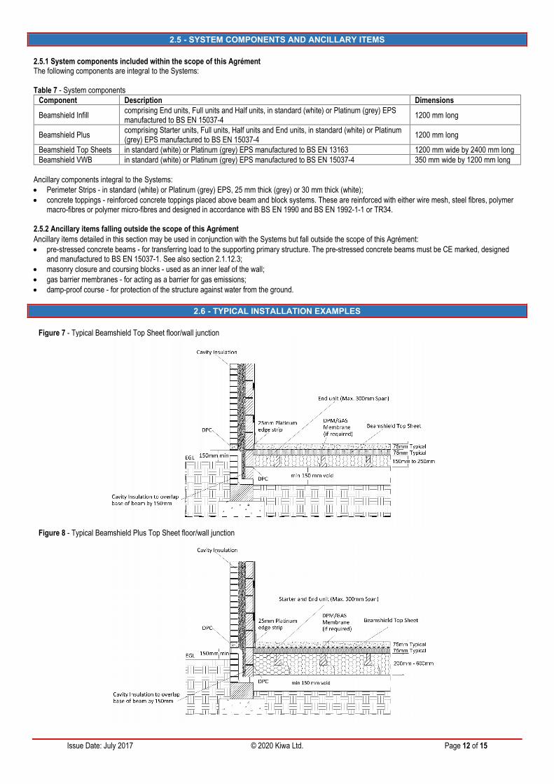
2.6 - TYPICAL INSTALLATION EXAMPLES
Figure 7 - Typical Beamshield Top Sheet floor/wall junction
Figure 8 - Typical Beamshield Plus Top Sheet floor/wall junction
Issue Date: July 2017 © 2020 Kiwa Ltd. Page 13 of 15
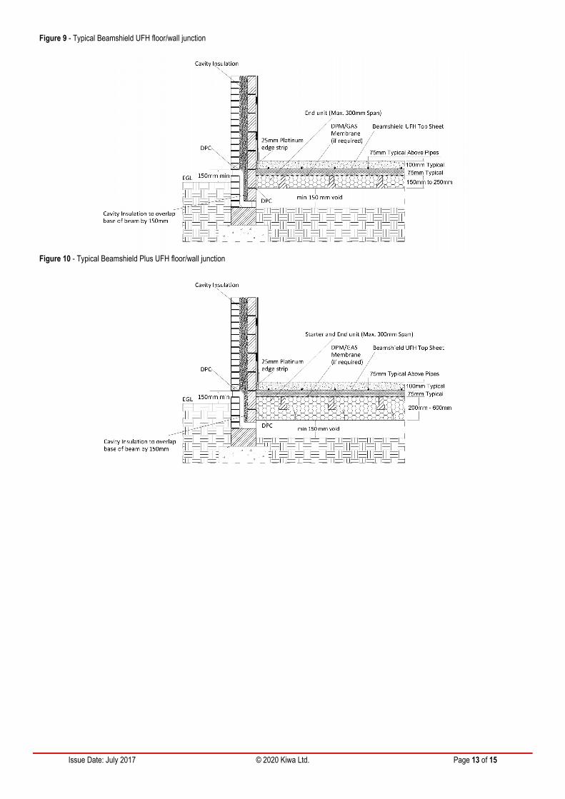
Figure 9 - Typical Beamshield UFH floor/wall junction
Figure 10 - Typical Beamshield Plus UFH floor/wall junction

Issue Date: July 2017 © 2020 Kiwa Ltd. Page 14 of 15
CHAPTER 3 - CDM, NATIONAL BUILDING REGULATIONS AND THIRD-PARTY ACCEPTANCE
3.1 - THE CONSTRUCTION (DESIGN AND MANAGEMENT) REGULATIONS 2015 AND THE CONSTRUCTION (DESIGN ANDMANAGEMENT) REGULATIONS (NORTHERN IRELAND) 2016
Information in this Agrément may assist the client, Principal Designer/CDM co-ordinator, designer and contractors to address their obligations under theseRegulations.
3.2 - THE NATIONAL BUILDING REGULATIONS
In the opinion of Kiwa Ltd., the Systems, if installed and used in accordance with Chapter 2 of this Agrément, can satisfy or contribute to satisfying the relevantrequirements of the following national Building Regulations.
3.2.1 - ENGLANDTHE BUILDING REGULATIONS 2010 AND SUBSEQUENT AMENDMENTS
A1 Loading - the Systems can sustain and transmit dead and imposed floor loads to the ground. C2(c) Resistance to moisture - the EPS units and boards will contribute to limiting the risk of surface and interstitial condensation. L1(a)(i) Conservation of fuel and power - the EPS units and boards will contribute to satisfying this Requirement. Regulation 7 Materials and workmanship - the EPS units and boards are manufactured from suitably safe and durable materials for their application and
can be installed to give a satisfactory performance. Regulation 26 - CO2 emission rates for new buildings - the EPS units and boards will contribute to satisfying this Regulation. Regulation 26A - Fabric energy efficiency rates for new dwellings - the EPS units and boards will contribute to satisfying this Regulation.
3.2.2 - WALESTHE BUILDING REGULATIONS 2010 AND SUBSEQUENT AMENDMENTS
A1 Loading - the Systems can sustain and transmit dead and imposed floor loads to the ground. C2(c) Resistance to moisture - the EPS units and boards will contribute to limiting the risk of surface and interstitial condensation. L1(a)(i) Conservation of fuel and power - the EPS units and boards will contribute to satisfying this Requirement. Regulation 7 Materials and workmanship - the EPS units and boards are manufactured from suitably safe and durable materials for their application and
can be installed to give a satisfactory performance. Regulation 26 - CO2 emission rates for new buildings - the EPS units and boards will contribute to satisfying this Regulation. Regulation 26A - Primary energy consumption rates for new buildings - the EPS units and boards will contribute to satisfying this Regulation. Regulation 26B - Fabric performance values for new dwellings - the EPS units and boards will contribute to satisfying this Regulation.
3.2.3 - SCOTLANDTHE BUILDING (SCOTLAND) REGULATIONS 2004 AND SUBSEQUENT AMENDMENTS
3.2.3.1 Regulations 8 (1)(2) Durability, workmanship and fitness of materials The EPS units and boards are manufactured from acceptable materials and are considered to be adequately resistant to deterioration and wear under
normal service conditions, provided they are installed in accordance with the requirements of this Agrément.3.2.3.2 Regulation 9 Building Standards - Construction 1.1(a)(b) Structure - the Systems can sustain and transmit dead and imposed floor loads to the ground. 3.15 Condensation - the EPS units and boards will contribute to limiting the risk of surface and interstitial condensation. 6 Energy - the EPS units and boards will contribute to satisfying the requirements of 6.1(b) - Carbon dioxide emissions, and 6.2 - Building insulation
envelope. 7.1(a)(b) Statement of sustainability - the EPS units and boards can contribute to satisfying the relevant Requirements of Regulation 9, Standards 1 to 6,
and therefore will contribute to a construction meeting a bronze level of sustainability as defined in this Standard. In addition, the EPS units and boards cancontribute to a construction meeting a higher level of sustainability as defined in this Standard.
3.2.3.3 Regulation 12 Building Standards - Conversions All comments given under Regulation 9 also apply to this Regulation, with reference to Schedule 6 of The Building (Scotland) Regulations 2004 and
subsequent amendments, and clause 0.12 of the Technical Handbook (Domestic).
3.2.4 - NORTHERN IRELANDTHE BUILDING REGULATIONS (NORTHERN IRELAND) 2012 AND SUBSEQUENT AMENDMENTS
23(a)(i)(iii)(b) Fitness of materials and workmanship - the EPS units and boards are manufactured from materials which are considered to be suitably safeand acceptable for use as thermal insulation.
28 Resistance to moisture and weather - the Systems can be constructed so as to prevent any harmful effect on the building or the health of the occupantscaused by the passage of moisture to any part of the building from (a) the ground and (b) the weather.
29 Condensation - the EPS units and boards will contribute to limiting the risk of surface and interstitial condensation. 30 Stability - when installed and used in accordance with this Agrément, the Systems can sustain and transmit dead and imposed floor loads to the ground. The EPS units and boards will contribute to satisfying the requirements of 39(a)(i) - Conservation measures, and 40(2) - Target carbon dioxide emission
rate.
Issue Date: July 2017 © 2020 Kiwa Ltd. Page 15 of 15
3.3 - THIRD-PARTY ACCEPTANCE
NHBC - In the opinion of Kiwa Ltd., the Systems, if installed, used and maintained in accordance with this Agrément, can satisfy or contribute to satisfying therelevant requirements in relation to NHBC Standards, Chapter 5.2.
CHAPTER 4 - SOURCES
BS EN ISO 10211:2017 Thermal bridges in building constructions. Calculation of heat flows and surface temperatures BS EN ISO 13370:2017 Thermal performance of buildings. Heat transfer via the ground. Calculation methods BS EN 206:2013+A1:2016 Concrete. Specification, performance, production and conformity BS EN 1990:2002+A1:2005 - Eurocode. Basis of structural design BS EN 1991-1-1:2002 - Eurocode 1: Actions on structures - Part 1-1: General actions - Densities, self-weight, imposed loads for buildings BS EN 1992-1-1:2004+A1:2014 Eurocode 2: Design of concrete structures. General rules and rules for buildings BS EN 12620:2002+A1:2008 Aggregates for concrete BS EN 13163:2012+A2:2016 Thermal insulation products for buildings. Factory made expanded polystyrene (EPS) products. Specification BS EN 14488-7:2006 Testing sprayed concrete. Fibre content of fibre reinforced concrete BS EN 14721:2005+A1:2007 Test method for metallic fibre concrete. Measuring the fibre content in fresh and hardened concrete BS EN 14889-1:2006 Fibres for concrete. Steel fibres. Definitions, specifications and conformity BS EN 14889-2:2006 Fibres for concrete. Polymer fibres. Definitions, specifications and conformity BS EN 15037-1:2008 Precast concrete products. Beam-and-block floor systems. Beams BS EN 15037-4:2010+A1:2013 Precast concrete products. Beam-and-block floor systems. Expanded polystyrene blocks BS 4483:2005 Steel fabric for the reinforcement of concrete. Specification BS 5250:2011+A1:2016 Code of practice for control of condensation in buildings BS 8102:2009 Code of practice for protection of below ground structures against water from the ground BS 8103-1:2011 Structural design of low-rise buildings. Code of practice for stability, site investigation, foundations, precast concrete floors and ground floor
slabs for housing BS 8500-1:2015+A2:2019 Concrete. Complementary British Standard to BS EN 206. Method of specifying and guidance for the specifier BS 8500-2:2015+A2:2019 Concrete. Complementary British Standard to BS EN 206. Specification for constituent materials and concrete CP 102:1973 Code of practice for protection of buildings against water from the ground BRE Information Paper IP 1/06 Assessing the effects of thermal bridging at junctions and around openings, February 2006 BR262 Thermal insulation: avoiding risks, 2002 edition BR443 Conventions for U-value calculations, 2006 edition, BRE Scotland BR497 Conventions for Calculating Linear thermal transmittance and Temperature Factors, 2016 edition Guide to the installation of Beamshield Plus and Platinum Beamshield Plus Suspended Floor Insulation Design Guide for Concrete Toppings to Beam & EPS Block Suspended Floors, MPA British Precast Flooring Federation, September 2017 NHBC Standards 2020, Chapter 4.2 Building near trees and Chapter 5.2 Suspended ground floors PAS 2030 - Building Fabric Measures (BFM) SAP 2012 Conventions, BRE Standard Assessment Procedure, 2015-10-20 (v 6.0) Technical Data Sheet Springvale Beamshield Flooring Insulation Systems Technical Report No.TR34:2018 TR 34 Concrete industrial ground floors - a guide to design and construction Thermal Bridging Guide - An introductory guide to thermal bridging in homes, Zero Carbon Hub, February 2016
Remark: apart from these sources, technical information and confidential reports have been assessed; any relevant documents are in the possession ofKiwa Ltd. and kept in the Technical Assessment File of this Agrément. The Installation Manual for the Systems may be subject to change, the Agrémentholder should be contacted for clarification of revision.
CHAPTER 5 - AMENDMENT HISTORY
Revision Amendment Description Amended By Approved By Date- Replaces BAF 17-056/01/A C Vurley C Forshaw March 2020A Amendment of fibre types C. Devine C. Vurley November 2020


![Apresentação BRE.pptx [Somente leitura] · APRESENTAÇÃO INICIAL. Nova Configuração Empresas BRE Araçatuba BRE Belo Horizonte BRE Brasília BRE Lauro de Freitas BRE Ribeirão](https://img.pdfslide.net/doc/110x75/5f2922d9461c9308dd412193/apresentao-brepptx-somente-leitura-apresentafo-inicial-nova-configurao.jpg)
![IAB190416 Carlow Concrete · 2020. 4. 21. · IP 1/06[2], BRE report BR 497[3] and I.S. EN ISO 10211[4]. As a result, best practice has been observed to limit heat loss due to thermal](https://img.pdfslide.net/doc/110x75/61335a06dfd10f4dd73b0812/iab190416-carlow-concrete-2020-4-21-ip-1062-bre-report-br-4973-and-is.jpg)


![BASF Polyurethane - Walltite - NSAI · 2020. 8. 11. · BRE report BR 497 [3] and I.S. EN ISO 10211 [4]. As a result, best practice has been observed to limit heat loss due to thermal](https://img.pdfslide.net/doc/110x75/61335a03dfd10f4dd73b0811/basf-polyurethane-walltite-nsai-2020-8-11-bre-report-br-497-3-and-is.jpg)