Embed Size (px)
Citation preview
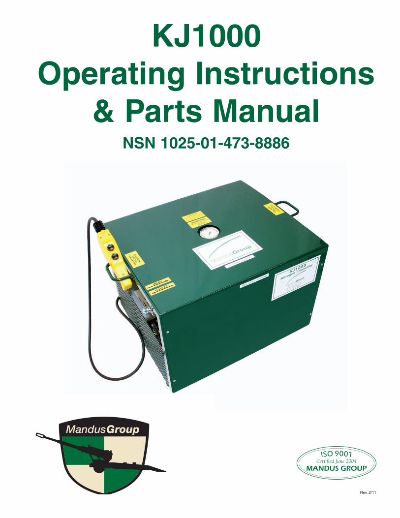
KJ1000 Operating Instructions
amp Parts Manual NSN 1025shy01shy473shy8886
Rev 211
ISO 9001 Certified June 2004
MANDUS GROUP
Mandus Group Ltd
KJ1000 Operators Manual
TABLE OF CONTENTS
General Safety Instructions Page 1 2
Operator InstructionsPage 3 4
KJ1000 Repair Parts ListPage 5
KJ1000 Repair Parts List Description Page 6
Nitrogen Reclaiming Instructions Page 7 8 9
Trouble Shooting Procedures Page 10
Electrical Schematic Page 11
KJ1000 Optional Products List Page 12 13
KJ4000 Information DataPage 14
KJ4000 Optional Products List Page 15
Warranty Information Page 16
GENERAL SAFETY INFORMATION
1 DO NOT operate the KJ1000 or any of its components without first reading and understanding all the operating instructions first
2 DO NOT operate the KJ1000 unless the oil level in the reservoir is 12 inch from the top of the reservoir
3 DO NOT operate the KJ1000 at temperatures greater than 110 degrees F or less than 5 degrees F
4 DO NOT operate the KJ1000 on less than a 20 amp service
5 DO NOT attempt to apply more than 2500 psi anywhere to the KJ1000
6 DO NOT attempt to lift the KJ1000 with less than two men The KJ1000 weighs approx 175 lbs
7 DO NOT attempt to use the KJ1000 and its accessories in any way other than their intended use
8 NEVER USE any oil in the KJ1000 other than the specified oil
GENERAL MAINTENANCE INFORMATION
1 Inspect all oil lines and connections twice a year for any cracks leaks or excessive wear
2 Inspect electric cord once a year for any excessive wear cracks or exposed wires
3 Change oil every 2 years
4 Change Nitrogen Extraction filter yearly
5 Inspect heat exchanger cooling fins once yearly for damage and dirt Clean with air hose if necessary
6 If a blowing oil mist is ever present when disconnecting Schrader Valves at equilibrators or at the recuperator the following steps may need to be taken
Step 1 Replace gas filter element in the Nitrogen Extraction Kit and determine if blowing oil mist stops If it does not perform step 2
Step 2 Contact Mandus Group Ltd for accumulator bladder replacement
Page 1
MANDUS GROUP 888shy922shy8502
SAFETY INSTRUCTIONS
SUMMARY The following are general safety precautions that are not related to any specific procedures and therefore do not appear else where in this manual These are general safety precautions that operators and maintenance personnel must understand and apply during many phases of operation and maintenance to ensure personal safety and protection of the equipment
Throughout this manual three types of notations are provided which contain special information
NOTE Provides additional information that may be helpful in performing a specific task
CAUTION Provides information about conditions which require special attention and precautions to avoid serious or fatal injuries
WARNING Provides information about conditions which require special attention and precautions to avoid serious or fatal injuries
GUIDELINES FOR HANDLING COMPRESSED GAS CYLINDERS bull Nitrogen cylinders are under extremely high pressure (up to 2500psi) and present a number of associated hazards as a result
bull The sudden release of the cylinder pressure whether by puncture damage to a valve caused by dropping or other means can turn the cylinder into a missile which can travel along the ground or through the air at high speeds Take extreme care when filling and handling charged cylinders
bull Do not drag or slide the cylinders by the pressure cap this may cause the sudden release of cylinder pressure Use a suitable hand truck fork lift or similar device for handling large cylinders
bull Do not drop cylinders or permit them to strike against each other or other surfaces this may cause the sudden release of pressure Securely secure the cylinders during filling storage and transport
bull Do not fill cylinders too rapidly excessive heat may build up in the gas which could result in a failure of the cylinder valve seals and possible fire Periodically check the surface temperature of the cylinders during charging
bull Never charge cylinders with nitrogen that are marked for other gasses Always check the cylinder markings and ensure that only cylinders marked for nitrogen are charged with nitrogen Do not use adapters to fill cylinders that do not have the correct fittings for nitrogen
WARNINGS bull Improper use of this product may cause severe personal injury of death Read and understand this manual before using or servicing this product
bull Make sure any equipment connected to the KJ1000 is rated for the applicable pneumatic pressure bull Only factory supplied assemblies may be interchanged to repair the KJ1000 Interchange of parts or assemblies between KJ1000 units may result in damaged parts or components and could void warranty
CAUTIONS bull Risk of electrical shock DO NOT remove covers Refer servicing to qualified service personnel bull Hose fittings must be leak tight A small leak can severely impair performance of the KJ1000 bull If an extension cord must be used to deliver power to the KJ1000 ensure that it is adequately sized and in good repair
bull Risk of electrical shock Refer servicing to qualified service personnel
Page 2
Page 3
OPERATING INSTRUCTIONS amp PARTS MANUAL Model KJ1000
Please read and save these instructions Read carefully before attempting to assemble install operate or maintain the product described Protect yourself and others by observing all safety information Failure to comply with instructions could result in personal injury andor property damage Retain instructions for future reference
Mandus Group Ltd KJ1000 2408 4th Avenue
Rock Island IL 61201 Nitrogen Intensifier 1shy888shy922shy8502
wwwmandusgroupcom
Description The KJ1000 Nitrogen Intensifier was developed to assist in filling nitrogen vessels The KJ1000 is designed to utilize and intensify all but 150 PSI of nitrogen from the supply bottle The KJ1000 accepts nitrogen from a supply source then intensifies the nitrogen source pressure by means of a hydraulic pump and electric motor The intensified nitrogen is then forced into an accepting nitrogen vessel The KJ1000 is engineered to shut down when 150 PSI or less is left in the supply bottle or when the factory set upper level pressure (1950PSI) is obtained
Unpacking KJ1000 When unpacking the KJ1000 inspect for any loose missing or damaged parts Notify Mandus Group Ltd as soon as possible if there are missing or damaged parts KJ1000 uses ISO100 antishyleak antishywear antishyfoam or equivalent hydraulic oil Unit is shipped with oil
General Safety Information 1 Do not use any gas but nitrogen in the KJ1000 2 Do not operate KJ1000 on less than a 20shyamp service
WARNING Do not exceed the maximum input or output pressure of 2500 psi or operate at temperatures lower than 5 degrees F or higher than 110 degrees F WARNING Never attempt to uncouple the quick connects anywhere on system while it is under pressure
Setshyup 1 Remove air chuck and coupling from the customer owned
nitrogen charging kit and install the male quick connect provided with the KJ1000 to the end of the hose
NOTE Remove needle valve from the valve stem if one is present in the equilibrator crossover line This allows a more efficient transfer process
NOTE Do not use a drop cord of more than 50 feet in length and wire gage of cord should be rated at 12 awg Failure to follow this information could result in damage to the KJ1000
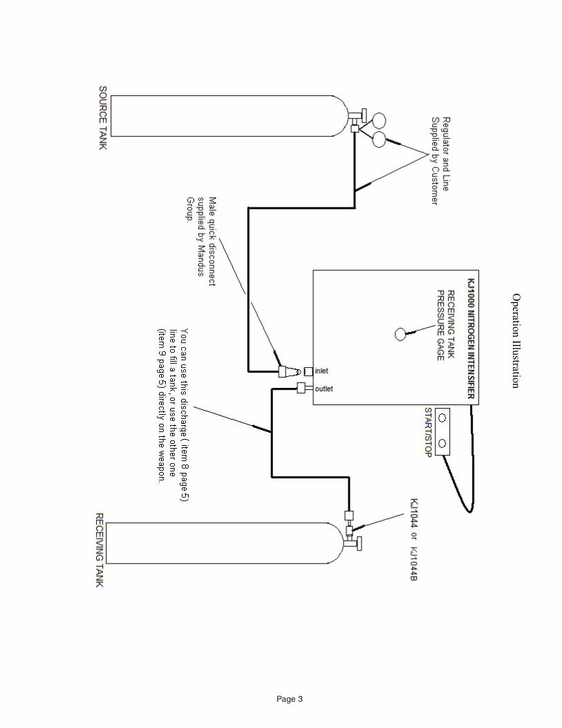
Operating Instructions The KJ1000 requires to be hooked up to a source tank with at least 150 psi (refer to illustration on page 3) The KJ1000 has a pressure switch in it that wonrsquot allow operation unless it has a minimum of 150 psi on the inlet line
There are 2 connection fittings on the KJ1000 They are right next to each other and are clearly marked on the cover as ldquoINLETrdquo and ldquoOUTLETrdquo The female quick disconnect is the inlet connection on the manifold The male quick disconnect on the manifold is the outlet Your source tank should have a regulator on it with a gas line coming off of it The end of this line must have a male quick disconnect on it to connect to the female quick disconnect on the KJ1000
YOU CANNOT USE A REGULATER ON THE RECEIVING TANK You must use the KJ1044 or KJ1044B There should be a 15 foot discharge hose with female disconnects on both ends This hose comes standard with the unit One end attaches to the KJ1000 and the other end attaches to the receiving tank via the KJ1044 or 1044B (the KJ1044 (CGA 580) is for tanks up to 3000 psi the KJ1044B (CGA 680) is for tanks from 3000 psi up to 5500 psi
Once you have both tanks (Source tank and Receiving tank) connected to the KJ1000 Turn the valves on both tanks slowly open until they are wide open The pressure gage on top of the KJ1000 illustrates the pressure in the receiving tank
Plug the KJ1000 in and press the start button on the hand pendant The unit should start to run and will continue running until the receiving tank reaches approximately 1850 psi or until you shut machine off
Page 4
KJ1000 Parts List
1
7
6
3
4
2
5
8 9 10
11
12
13
14 15
16
Page 5
12345678910 111213141516
Repair Parts List
Ref Number Part Number Description KJ1000FA Frame Assembly KJ1000PU Power Unit Assembly KJ1000EX Heat Exchanger Assembly KJ1000MA Manifold Assembly KJ1000EK Extraction Kit Assembly KJ1000AA Accumulator Assembly KJ1000EA Electrical Assembly KJ1000H1 Hose Assembly 1 KJ1000H2 Hose Assembly 2 400077LW 25 Ft Drop Cord KJ1000A1 Adapter Assembly 9928070 Female Disconnect 9928020 Male Disconnect KJ1044 Tank Fill Stem (3000 PSI) KJ1044B Tank Fill Stem (5500 PSI) KJ1000FE Filter Element
Page 6
or to
or you
will
ou must to
into
into
to
on to
to on to
you to in
Figure A
INSTRUCTIONS FOR RECLAIMING NITROGEN FROM AN M198 HOWITZER
1 Tank Fill Stem Assembly KJ1044 KJ 1044B (Item 14 and 15 Page 5) should be attached a standard nitrogen tank with a CGA580 CGA680 valve respectively that are transferring nitrogen TO
NOTE - When this destination tank reaches approximately 1950 PSI the KJ1000 shut down Y then connect Tank Fill Stem another available tank with less than 1950 PSI
NOTE It is assumed that the operator of this equipment is already familiar with the KJ1000 and its operation Make sure you have read the KJ1000 operating instructions and thoroughly understand them Failure to do this could cause serious injury
2 Install the adapter (Item 11 Page 5) the female quick connect end of the discharge hose (see figure A) Use discharge hose with Schrader gas chuck attached (see Page 5 Item 9)
3 Now install the adapter end of the discharge hose from step 2 the inlet side of the KJ1000 (refer Page 8)
4 Attach one end of the second discharge hose (female disconnect each end - refer Page 5 Item 8) the male quick connect the KJ1000 (Page 8) Attach the other end of this hose the Tank Stem
Kit that attached the receiving tank step 1
Page 7
Figure B
Page 8
NOTE Remove needle valve from the valve stem if one is present in the equilibrator crossover line This allows a more efficient transfer process
5 Attach the gas chuck end of the discharge hose with the adapter to the valve on the crossover line or to the Schrader valve on the recuperatorequilibrator
6 Plug the KJ1000 in to your electrical source 7 Slowly open the tank valve on the receiving tank until it is fully open 8 Slowly open the Schrader valve (or valves) at the equilibrator or the recuperator until fully open 9 When the nitrogen supply and source vessel pressures have equalized turn on the KJ1000 10 Run the KJ1000 for approximately 20 minutes and then turn it off (Unless it turns off automatically
The KJ1000 is designed to turn off when supply pressure drops below 150 psi) After 20 minutes you will have reclaimed all but 150 psi of the nitrogen in your supply vessel
IMPORTANT You still have residual pressure in the equilibrator set or recuperator This pressure must be bled off if maintenance is to be performed
11 Close the Schrader valve on the equilibrators or recuperator and also turn off the receiving tank valve Slowly bleed off nitrogen pressure within the KJ1000 and lines by cracking the bleed valve on the discharge hose (refer to Page 5 Item 9) Make sure the pressure gage on the KJ1000 reads 0 (zero) PSI before disconnecting lines
Note Mandus Group Ltd recommends that the customer replace the nitrogen filter element annually Contact Mandus Group Ltd for ordering information
Page 9
Problem Possible Solution 1 KJ1000 wonrsquot turn on 1 Circuit breaker off in control panel
2 Not plugged in 3 Supply pressure not open 4 Supply pressure less than 150 PSI 5 Destination pressure is above 1950 PSI
2 KJ1000 wonrsquot fill vessel 1 Kink in inlet line 2 Obstruction in inlet line 3 Kink in outlet line 4 Needle valves not removed 5 Schrader valve is bad 6 Low oil in reservoir 7 Drop cord is over 50 ft long 8 Drop cord is not 12 AWG 9 Supply pressure is below 200 PSI
3 Oil mist present when disconnecting Schrader Valve
Step 1 Replace gas filter element in the Nitrogen Extraction filter and determine
oil mist stops If it does not perform step 2 Step 2 Contact Mandus Group Ltd for accumulator bladder replacement
Trouble Shooting the KJ1000
Page 10
N
N
_
r
N
r ror
r
or
N
N
Page 11
Product Number Product Description
KJ1045 System Cart shy 5rsquo High
KJ1046 System Cart shy 32rsquo High
KJ1041 Gage Set
KJ1042 Crossover Line
KJ1043 Nitrogen Discharge Hose
KJ1044 Tank Fill Stem (3000 PSI)
KJ1044B Tank Fill Stem (5500 PSI)
KJ1047 Tank Regulator Set
KJ1048 Nitrogen Extraction Kit
KJ1000 Nitrogen Intensifier
OPTIONAL PRODUCTS LIST
See next page for photos and product descriptions
To Order Call 1shy888shy922shy8502 Mandus Group Ltd 2408 4th Avenue
Rock Island IL 61201 1shy888shy922shy8502
wwwmandusgroupcom
Page 12
KJ1045 5rdquo Cart ndash For use with the KJ4000 Oil Transfer System or KJ1000 Nitrogen Intensifier
KJ1046 32rdquo Cart ndash For use with the KJ4000 Oil Transfer System or KJ1000 Nitrogen Intensifier
KJ1041 Gage Set ndash For checking and bleeding nitrogen pressure in equilibrators and recuperators on the 198 Howitzer
KJ1047 Tank Regulator Set ndash For use with 2000 PSI nitrogen tanks Delivery range 0 to 2500 PSI Comes with 15 ft discharge hose to couple up with KJ1000
KJ1044 Tank Fill Stem ndash For use with the KJ1000 Nitrogen Intensifier and the KJ1043 Nitrogen Discharge Hose The tank fill stem allows consolidation of low pressure nitrogen bottles into one tank at pressures from 0 to 3000 PSI
KJ1043 Nitrogen Discharge Hose ndash For use with the KJ1000 Nitrogen Intensifier and KJ1042 Crossover Line or to be used with the KJ1000 Nitrogen Intensifier and the KJ1044 Tank Fill Stem
KJ1044B Tank Fill Stem ndash For use with the KJ1000 Nitrogen Intensifier and the KJ1043 Nitrogen Discharge Hose The tank fill stem allows consolidation of low pressure nitrogen bottles into one tank at pressures from 0 to 5500 PSI
KJ1042 Crossover Line ndash To be used with the KJ1000 Nitrogen Intensifier to fill equilibrators on a 198 Howitzer Can couple up with the standard discharge hose on the KJ1000 or the KJ1043 Nitrogen Discharge Hose
Page 13
KJ4000Oil Transfer System
KJ4000 Oil Transfer System
NSN 1025shy01shy473shy7710
The KJ4000 Oil Transfer System is a newly developed technology for use as an alternative to the M3 oil pump currently being used by all branches of the Armed Services The KJ4000 provides 59 GPM of oil flow for ease in filling oil reservoirs as well as recoil mechanisms buffers and replenishers The KJ4000 can provide oil pressure up to 2500 PSI The KJ4000 is engineered to self purge its system and lines of air prior to pumping oil The KJ4000 accepts oils from pressurized systems through the same line it discharges from by means of an innovative design This design allows oil to flow through a 5 micron high pressure filter in either direction whether it is from a pressurized system or to a pressurized system or reservoir
Available Options
bull An alternative to the M3 oil pump bull 5 gallon reservoir with sight glass bull Increases productivity (standard option) bull 59 GPM of flow bull Self purging design to eliminate pumping bull Manual hand pump backshyup 7 cubic air into a closed system
inches per cycle bull Quick disconnects on all fittings and hoses bull 5 micron filter for transferring fluids to and bull 15 foot oil transfer hose (standard option)
from pressurized system bull Eliminates need for waste oil disposal bull Indicator gage for alerting user when 5 bull Size 20 W X 21 D X 22 12 H
micron filter change is required bull Weight 145 lbs bull 1 Year Warranty
bull 8 gallon reservoir bull 25 foot power supply cord bull 20 and 25 foot oil transfer hose bull Digital totalizing meter
Mandus Group Ltd 2408 4th Avenue TollshyFree (888) 922shy8502 Rock Island IL 61201 wwwmandusgroupcom
Page 14
To Order Call 1shy888shy922shy8502 Mandus Group Ltd 2408 4th Avenue
Rock Island IL 61201 1shy888shy922shy8502
wwwmandusgroupcom
Page 15
Mandus Group Ltd Manufacturerrsquos Limited Warranty
For one year from date of purchase Mandus Group Ltd will repair or replace at its expense and at its option any KJ4000 machine part or machine accessory which in normal use has proven to be defective in workmanship or material provided that the customer returns the product prepaid to Mandus Group Ltdrsquos repair service center and provides Mandus Group Ltd with reasonable opportunity to verify the defects by inspection Mandus Group Ltd will not be responsible for any asserted defect which has resulted from normal wear misuse abuse or repair or alteration made or specifically authorized by
anyone other than an authorized Mandus Group Ltd service facility or representative Under no circumstances will Mandus Group Ltd be liable for incidental or consequential damages resulting from defective products This warranty is Mandus Grouprsquos sole warranty and sets forth the customer exclusive remedy with respect to defective products All other warranties expressed or implied whether of merchantability fitness of purpose or otherwise are expressly disclaimed by Mandus Group Ltd
Page 16
Mandus Group Ltd
KJ1000 Operators Manual
TABLE OF CONTENTS
General Safety Instructions Page 1 2
Operator InstructionsPage 3 4
KJ1000 Repair Parts ListPage 5
KJ1000 Repair Parts List Description Page 6
Nitrogen Reclaiming Instructions Page 7 8 9
Trouble Shooting Procedures Page 10
Electrical Schematic Page 11
KJ1000 Optional Products List Page 12 13
KJ4000 Information DataPage 14
KJ4000 Optional Products List Page 15
Warranty Information Page 16
GENERAL SAFETY INFORMATION
1 DO NOT operate the KJ1000 or any of its components without first reading and understanding all the operating instructions first
2 DO NOT operate the KJ1000 unless the oil level in the reservoir is 12 inch from the top of the reservoir
3 DO NOT operate the KJ1000 at temperatures greater than 110 degrees F or less than 5 degrees F
4 DO NOT operate the KJ1000 on less than a 20 amp service
5 DO NOT attempt to apply more than 2500 psi anywhere to the KJ1000
6 DO NOT attempt to lift the KJ1000 with less than two men The KJ1000 weighs approx 175 lbs
7 DO NOT attempt to use the KJ1000 and its accessories in any way other than their intended use
8 NEVER USE any oil in the KJ1000 other than the specified oil
GENERAL MAINTENANCE INFORMATION
1 Inspect all oil lines and connections twice a year for any cracks leaks or excessive wear
2 Inspect electric cord once a year for any excessive wear cracks or exposed wires
3 Change oil every 2 years
4 Change Nitrogen Extraction filter yearly
5 Inspect heat exchanger cooling fins once yearly for damage and dirt Clean with air hose if necessary
6 If a blowing oil mist is ever present when disconnecting Schrader Valves at equilibrators or at the recuperator the following steps may need to be taken
Step 1 Replace gas filter element in the Nitrogen Extraction Kit and determine if blowing oil mist stops If it does not perform step 2
Step 2 Contact Mandus Group Ltd for accumulator bladder replacement
Page 1
MANDUS GROUP 888shy922shy8502
SAFETY INSTRUCTIONS
SUMMARY The following are general safety precautions that are not related to any specific procedures and therefore do not appear else where in this manual These are general safety precautions that operators and maintenance personnel must understand and apply during many phases of operation and maintenance to ensure personal safety and protection of the equipment
Throughout this manual three types of notations are provided which contain special information
NOTE Provides additional information that may be helpful in performing a specific task
CAUTION Provides information about conditions which require special attention and precautions to avoid serious or fatal injuries
WARNING Provides information about conditions which require special attention and precautions to avoid serious or fatal injuries
GUIDELINES FOR HANDLING COMPRESSED GAS CYLINDERS bull Nitrogen cylinders are under extremely high pressure (up to 2500psi) and present a number of associated hazards as a result
bull The sudden release of the cylinder pressure whether by puncture damage to a valve caused by dropping or other means can turn the cylinder into a missile which can travel along the ground or through the air at high speeds Take extreme care when filling and handling charged cylinders
bull Do not drag or slide the cylinders by the pressure cap this may cause the sudden release of cylinder pressure Use a suitable hand truck fork lift or similar device for handling large cylinders
bull Do not drop cylinders or permit them to strike against each other or other surfaces this may cause the sudden release of pressure Securely secure the cylinders during filling storage and transport
bull Do not fill cylinders too rapidly excessive heat may build up in the gas which could result in a failure of the cylinder valve seals and possible fire Periodically check the surface temperature of the cylinders during charging
bull Never charge cylinders with nitrogen that are marked for other gasses Always check the cylinder markings and ensure that only cylinders marked for nitrogen are charged with nitrogen Do not use adapters to fill cylinders that do not have the correct fittings for nitrogen
WARNINGS bull Improper use of this product may cause severe personal injury of death Read and understand this manual before using or servicing this product
bull Make sure any equipment connected to the KJ1000 is rated for the applicable pneumatic pressure bull Only factory supplied assemblies may be interchanged to repair the KJ1000 Interchange of parts or assemblies between KJ1000 units may result in damaged parts or components and could void warranty
CAUTIONS bull Risk of electrical shock DO NOT remove covers Refer servicing to qualified service personnel bull Hose fittings must be leak tight A small leak can severely impair performance of the KJ1000 bull If an extension cord must be used to deliver power to the KJ1000 ensure that it is adequately sized and in good repair
bull Risk of electrical shock Refer servicing to qualified service personnel
Page 2
Page 3
OPERATING INSTRUCTIONS amp PARTS MANUAL Model KJ1000
Please read and save these instructions Read carefully before attempting to assemble install operate or maintain the product described Protect yourself and others by observing all safety information Failure to comply with instructions could result in personal injury andor property damage Retain instructions for future reference
Mandus Group Ltd KJ1000 2408 4th Avenue
Rock Island IL 61201 Nitrogen Intensifier 1shy888shy922shy8502
wwwmandusgroupcom
Description The KJ1000 Nitrogen Intensifier was developed to assist in filling nitrogen vessels The KJ1000 is designed to utilize and intensify all but 150 PSI of nitrogen from the supply bottle The KJ1000 accepts nitrogen from a supply source then intensifies the nitrogen source pressure by means of a hydraulic pump and electric motor The intensified nitrogen is then forced into an accepting nitrogen vessel The KJ1000 is engineered to shut down when 150 PSI or less is left in the supply bottle or when the factory set upper level pressure (1950PSI) is obtained
Unpacking KJ1000 When unpacking the KJ1000 inspect for any loose missing or damaged parts Notify Mandus Group Ltd as soon as possible if there are missing or damaged parts KJ1000 uses ISO100 antishyleak antishywear antishyfoam or equivalent hydraulic oil Unit is shipped with oil
General Safety Information 1 Do not use any gas but nitrogen in the KJ1000 2 Do not operate KJ1000 on less than a 20shyamp service
WARNING Do not exceed the maximum input or output pressure of 2500 psi or operate at temperatures lower than 5 degrees F or higher than 110 degrees F WARNING Never attempt to uncouple the quick connects anywhere on system while it is under pressure
Setshyup 1 Remove air chuck and coupling from the customer owned
nitrogen charging kit and install the male quick connect provided with the KJ1000 to the end of the hose
NOTE Remove needle valve from the valve stem if one is present in the equilibrator crossover line This allows a more efficient transfer process
NOTE Do not use a drop cord of more than 50 feet in length and wire gage of cord should be rated at 12 awg Failure to follow this information could result in damage to the KJ1000
Operating Instructions The KJ1000 requires to be hooked up to a source tank with at least 150 psi (refer to illustration on page 3) The KJ1000 has a pressure switch in it that wonrsquot allow operation unless it has a minimum of 150 psi on the inlet line
There are 2 connection fittings on the KJ1000 They are right next to each other and are clearly marked on the cover as ldquoINLETrdquo and ldquoOUTLETrdquo The female quick disconnect is the inlet connection on the manifold The male quick disconnect on the manifold is the outlet Your source tank should have a regulator on it with a gas line coming off of it The end of this line must have a male quick disconnect on it to connect to the female quick disconnect on the KJ1000
YOU CANNOT USE A REGULATER ON THE RECEIVING TANK You must use the KJ1044 or KJ1044B There should be a 15 foot discharge hose with female disconnects on both ends This hose comes standard with the unit One end attaches to the KJ1000 and the other end attaches to the receiving tank via the KJ1044 or 1044B (the KJ1044 (CGA 580) is for tanks up to 3000 psi the KJ1044B (CGA 680) is for tanks from 3000 psi up to 5500 psi
Once you have both tanks (Source tank and Receiving tank) connected to the KJ1000 Turn the valves on both tanks slowly open until they are wide open The pressure gage on top of the KJ1000 illustrates the pressure in the receiving tank
Plug the KJ1000 in and press the start button on the hand pendant The unit should start to run and will continue running until the receiving tank reaches approximately 1850 psi or until you shut machine off
Page 4
KJ1000 Parts List
1
7
6
3
4
2
5
8 9 10
11
12
13
14 15
16
Page 5
12345678910 111213141516
Repair Parts List
Ref Number Part Number Description KJ1000FA Frame Assembly KJ1000PU Power Unit Assembly KJ1000EX Heat Exchanger Assembly KJ1000MA Manifold Assembly KJ1000EK Extraction Kit Assembly KJ1000AA Accumulator Assembly KJ1000EA Electrical Assembly KJ1000H1 Hose Assembly 1 KJ1000H2 Hose Assembly 2 400077LW 25 Ft Drop Cord KJ1000A1 Adapter Assembly 9928070 Female Disconnect 9928020 Male Disconnect KJ1044 Tank Fill Stem (3000 PSI) KJ1044B Tank Fill Stem (5500 PSI) KJ1000FE Filter Element
Page 6
or to
or you
will
ou must to
into
into
to
on to
to on to
you to in
Figure A
INSTRUCTIONS FOR RECLAIMING NITROGEN FROM AN M198 HOWITZER
1 Tank Fill Stem Assembly KJ1044 KJ 1044B (Item 14 and 15 Page 5) should be attached a standard nitrogen tank with a CGA580 CGA680 valve respectively that are transferring nitrogen TO
NOTE - When this destination tank reaches approximately 1950 PSI the KJ1000 shut down Y then connect Tank Fill Stem another available tank with less than 1950 PSI
NOTE It is assumed that the operator of this equipment is already familiar with the KJ1000 and its operation Make sure you have read the KJ1000 operating instructions and thoroughly understand them Failure to do this could cause serious injury
2 Install the adapter (Item 11 Page 5) the female quick connect end of the discharge hose (see figure A) Use discharge hose with Schrader gas chuck attached (see Page 5 Item 9)
3 Now install the adapter end of the discharge hose from step 2 the inlet side of the KJ1000 (refer Page 8)
4 Attach one end of the second discharge hose (female disconnect each end - refer Page 5 Item 8) the male quick connect the KJ1000 (Page 8) Attach the other end of this hose the Tank Stem
Kit that attached the receiving tank step 1
Page 7
Figure B
Page 8
NOTE Remove needle valve from the valve stem if one is present in the equilibrator crossover line This allows a more efficient transfer process
5 Attach the gas chuck end of the discharge hose with the adapter to the valve on the crossover line or to the Schrader valve on the recuperatorequilibrator
6 Plug the KJ1000 in to your electrical source 7 Slowly open the tank valve on the receiving tank until it is fully open 8 Slowly open the Schrader valve (or valves) at the equilibrator or the recuperator until fully open 9 When the nitrogen supply and source vessel pressures have equalized turn on the KJ1000 10 Run the KJ1000 for approximately 20 minutes and then turn it off (Unless it turns off automatically
The KJ1000 is designed to turn off when supply pressure drops below 150 psi) After 20 minutes you will have reclaimed all but 150 psi of the nitrogen in your supply vessel
IMPORTANT You still have residual pressure in the equilibrator set or recuperator This pressure must be bled off if maintenance is to be performed
11 Close the Schrader valve on the equilibrators or recuperator and also turn off the receiving tank valve Slowly bleed off nitrogen pressure within the KJ1000 and lines by cracking the bleed valve on the discharge hose (refer to Page 5 Item 9) Make sure the pressure gage on the KJ1000 reads 0 (zero) PSI before disconnecting lines
Note Mandus Group Ltd recommends that the customer replace the nitrogen filter element annually Contact Mandus Group Ltd for ordering information
Page 9
Problem Possible Solution 1 KJ1000 wonrsquot turn on 1 Circuit breaker off in control panel
2 Not plugged in 3 Supply pressure not open 4 Supply pressure less than 150 PSI 5 Destination pressure is above 1950 PSI
2 KJ1000 wonrsquot fill vessel 1 Kink in inlet line 2 Obstruction in inlet line 3 Kink in outlet line 4 Needle valves not removed 5 Schrader valve is bad 6 Low oil in reservoir 7 Drop cord is over 50 ft long 8 Drop cord is not 12 AWG 9 Supply pressure is below 200 PSI
3 Oil mist present when disconnecting Schrader Valve
Step 1 Replace gas filter element in the Nitrogen Extraction filter and determine
oil mist stops If it does not perform step 2 Step 2 Contact Mandus Group Ltd for accumulator bladder replacement
Trouble Shooting the KJ1000
Page 10
N
N
_
r
N
r ror
r
or
N
N
Page 11
Product Number Product Description
KJ1045 System Cart shy 5rsquo High
KJ1046 System Cart shy 32rsquo High
KJ1041 Gage Set
KJ1042 Crossover Line
KJ1043 Nitrogen Discharge Hose
KJ1044 Tank Fill Stem (3000 PSI)
KJ1044B Tank Fill Stem (5500 PSI)
KJ1047 Tank Regulator Set
KJ1048 Nitrogen Extraction Kit
KJ1000 Nitrogen Intensifier
OPTIONAL PRODUCTS LIST
See next page for photos and product descriptions
To Order Call 1shy888shy922shy8502 Mandus Group Ltd 2408 4th Avenue
Rock Island IL 61201 1shy888shy922shy8502
wwwmandusgroupcom
Page 12
KJ1045 5rdquo Cart ndash For use with the KJ4000 Oil Transfer System or KJ1000 Nitrogen Intensifier
KJ1046 32rdquo Cart ndash For use with the KJ4000 Oil Transfer System or KJ1000 Nitrogen Intensifier
KJ1041 Gage Set ndash For checking and bleeding nitrogen pressure in equilibrators and recuperators on the 198 Howitzer
KJ1047 Tank Regulator Set ndash For use with 2000 PSI nitrogen tanks Delivery range 0 to 2500 PSI Comes with 15 ft discharge hose to couple up with KJ1000
KJ1044 Tank Fill Stem ndash For use with the KJ1000 Nitrogen Intensifier and the KJ1043 Nitrogen Discharge Hose The tank fill stem allows consolidation of low pressure nitrogen bottles into one tank at pressures from 0 to 3000 PSI
KJ1043 Nitrogen Discharge Hose ndash For use with the KJ1000 Nitrogen Intensifier and KJ1042 Crossover Line or to be used with the KJ1000 Nitrogen Intensifier and the KJ1044 Tank Fill Stem
KJ1044B Tank Fill Stem ndash For use with the KJ1000 Nitrogen Intensifier and the KJ1043 Nitrogen Discharge Hose The tank fill stem allows consolidation of low pressure nitrogen bottles into one tank at pressures from 0 to 5500 PSI
KJ1042 Crossover Line ndash To be used with the KJ1000 Nitrogen Intensifier to fill equilibrators on a 198 Howitzer Can couple up with the standard discharge hose on the KJ1000 or the KJ1043 Nitrogen Discharge Hose
Page 13
KJ4000Oil Transfer System
KJ4000 Oil Transfer System
NSN 1025shy01shy473shy7710
The KJ4000 Oil Transfer System is a newly developed technology for use as an alternative to the M3 oil pump currently being used by all branches of the Armed Services The KJ4000 provides 59 GPM of oil flow for ease in filling oil reservoirs as well as recoil mechanisms buffers and replenishers The KJ4000 can provide oil pressure up to 2500 PSI The KJ4000 is engineered to self purge its system and lines of air prior to pumping oil The KJ4000 accepts oils from pressurized systems through the same line it discharges from by means of an innovative design This design allows oil to flow through a 5 micron high pressure filter in either direction whether it is from a pressurized system or to a pressurized system or reservoir
Available Options
bull An alternative to the M3 oil pump bull 5 gallon reservoir with sight glass bull Increases productivity (standard option) bull 59 GPM of flow bull Self purging design to eliminate pumping bull Manual hand pump backshyup 7 cubic air into a closed system
inches per cycle bull Quick disconnects on all fittings and hoses bull 5 micron filter for transferring fluids to and bull 15 foot oil transfer hose (standard option)
from pressurized system bull Eliminates need for waste oil disposal bull Indicator gage for alerting user when 5 bull Size 20 W X 21 D X 22 12 H
micron filter change is required bull Weight 145 lbs bull 1 Year Warranty
bull 8 gallon reservoir bull 25 foot power supply cord bull 20 and 25 foot oil transfer hose bull Digital totalizing meter
Mandus Group Ltd 2408 4th Avenue TollshyFree (888) 922shy8502 Rock Island IL 61201 wwwmandusgroupcom
Page 14
To Order Call 1shy888shy922shy8502 Mandus Group Ltd 2408 4th Avenue
Rock Island IL 61201 1shy888shy922shy8502
wwwmandusgroupcom
Page 15
Mandus Group Ltd Manufacturerrsquos Limited Warranty
For one year from date of purchase Mandus Group Ltd will repair or replace at its expense and at its option any KJ4000 machine part or machine accessory which in normal use has proven to be defective in workmanship or material provided that the customer returns the product prepaid to Mandus Group Ltdrsquos repair service center and provides Mandus Group Ltd with reasonable opportunity to verify the defects by inspection Mandus Group Ltd will not be responsible for any asserted defect which has resulted from normal wear misuse abuse or repair or alteration made or specifically authorized by
anyone other than an authorized Mandus Group Ltd service facility or representative Under no circumstances will Mandus Group Ltd be liable for incidental or consequential damages resulting from defective products This warranty is Mandus Grouprsquos sole warranty and sets forth the customer exclusive remedy with respect to defective products All other warranties expressed or implied whether of merchantability fitness of purpose or otherwise are expressly disclaimed by Mandus Group Ltd
Page 16
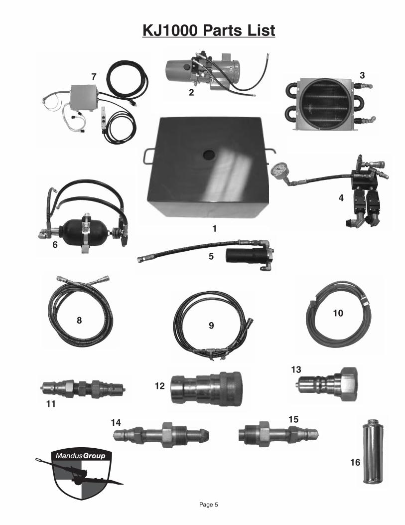
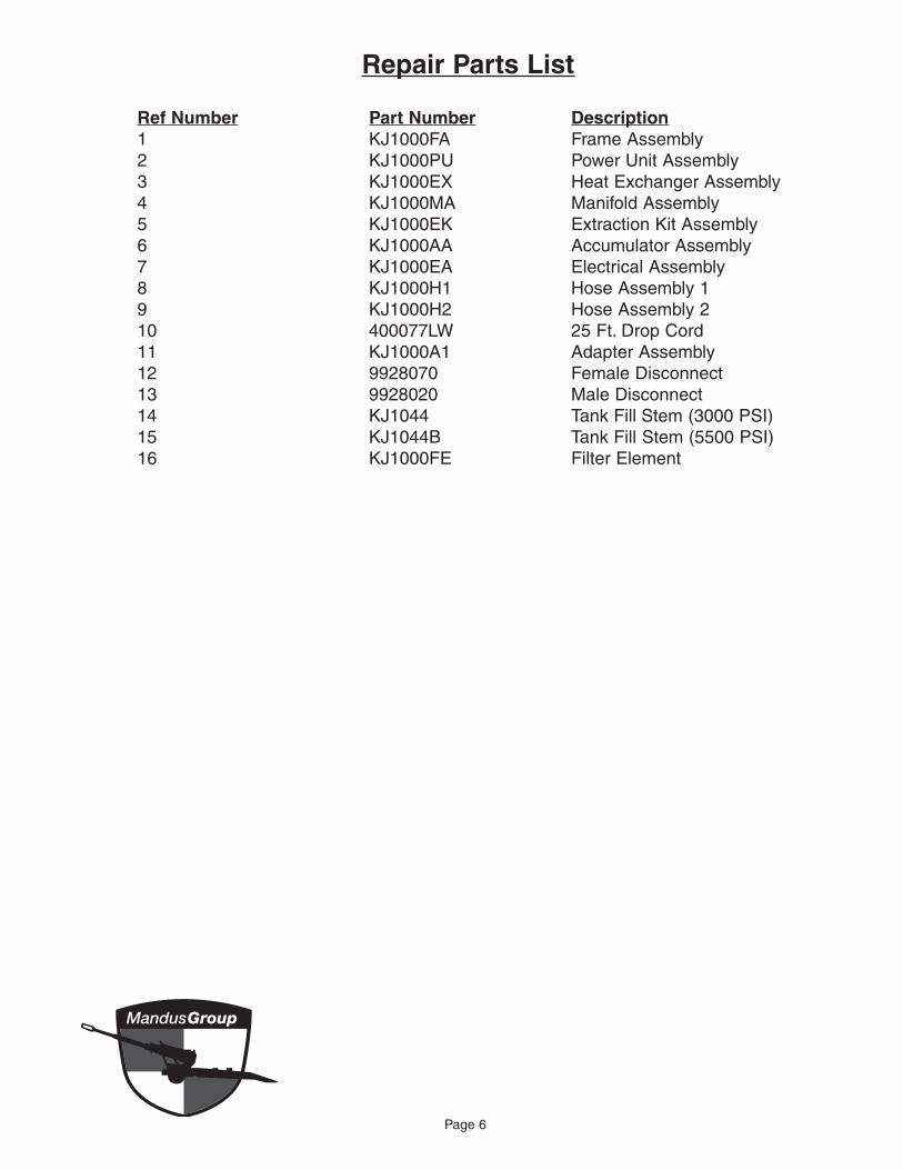
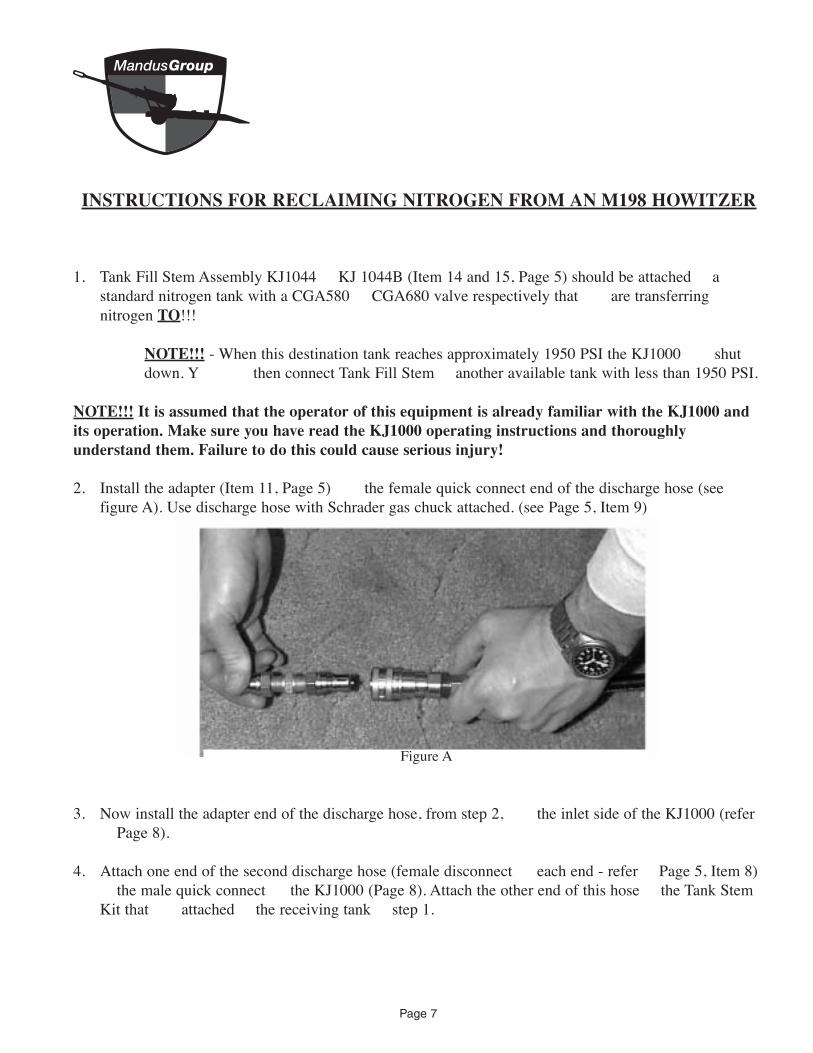
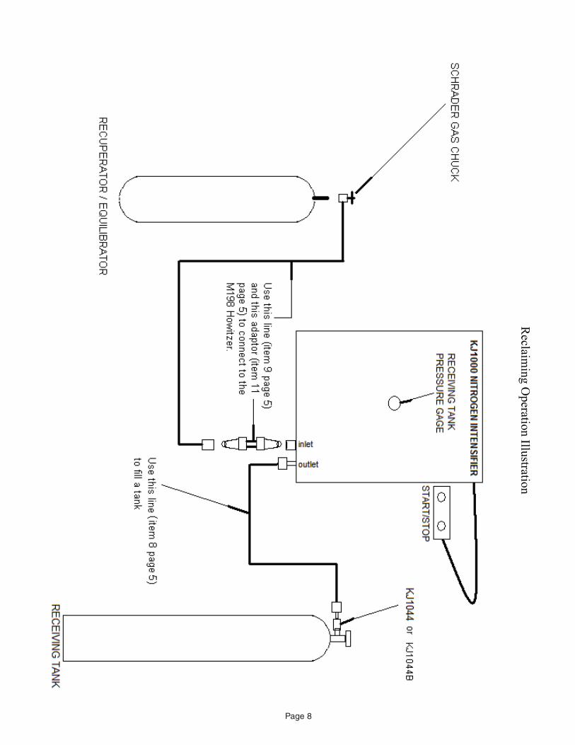
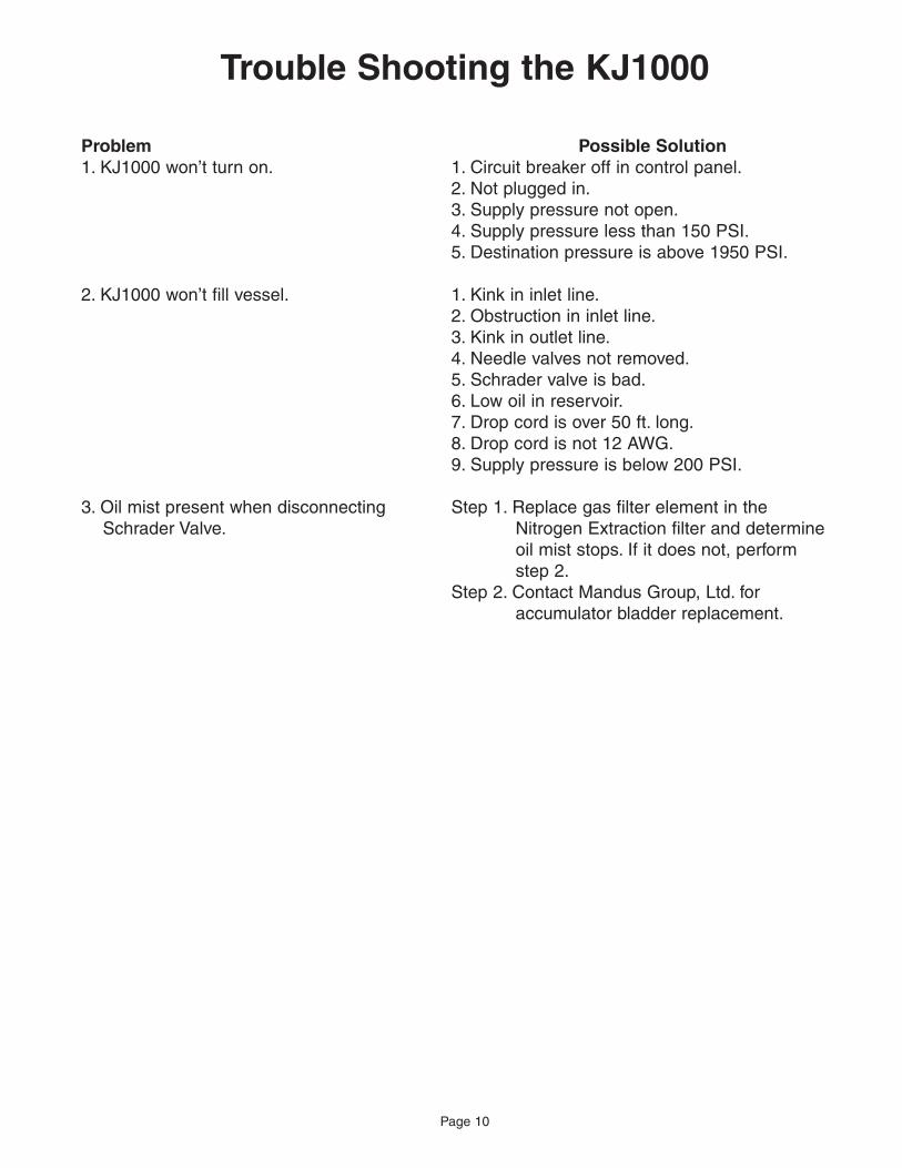
N
N
_
r
N
r ror
r
or
N
N
Page 11
Product Number Product Description
KJ1045 System Cart shy 5rsquo High
KJ1046 System Cart shy 32rsquo High
KJ1041 Gage Set
KJ1042 Crossover Line
KJ1043 Nitrogen Discharge Hose
KJ1044 Tank Fill Stem (3000 PSI)
KJ1044B Tank Fill Stem (5500 PSI)
KJ1047 Tank Regulator Set
KJ1048 Nitrogen Extraction Kit
KJ1000 Nitrogen Intensifier
OPTIONAL PRODUCTS LIST
See next page for photos and product descriptions
To Order Call 1shy888shy922shy8502 Mandus Group Ltd 2408 4th Avenue
Rock Island IL 61201 1shy888shy922shy8502
wwwmandusgroupcom
Page 12
KJ1045 5rdquo Cart ndash For use with the KJ4000 Oil Transfer System or KJ1000 Nitrogen Intensifier
KJ1046 32rdquo Cart ndash For use with the KJ4000 Oil Transfer System or KJ1000 Nitrogen Intensifier
KJ1041 Gage Set ndash For checking and bleeding nitrogen pressure in equilibrators and recuperators on the 198 Howitzer
KJ1047 Tank Regulator Set ndash For use with 2000 PSI nitrogen tanks Delivery range 0 to 2500 PSI Comes with 15 ft discharge hose to couple up with KJ1000
KJ1044 Tank Fill Stem ndash For use with the KJ1000 Nitrogen Intensifier and the KJ1043 Nitrogen Discharge Hose The tank fill stem allows consolidation of low pressure nitrogen bottles into one tank at pressures from 0 to 3000 PSI
KJ1043 Nitrogen Discharge Hose ndash For use with the KJ1000 Nitrogen Intensifier and KJ1042 Crossover Line or to be used with the KJ1000 Nitrogen Intensifier and the KJ1044 Tank Fill Stem
KJ1044B Tank Fill Stem ndash For use with the KJ1000 Nitrogen Intensifier and the KJ1043 Nitrogen Discharge Hose The tank fill stem allows consolidation of low pressure nitrogen bottles into one tank at pressures from 0 to 5500 PSI
KJ1042 Crossover Line ndash To be used with the KJ1000 Nitrogen Intensifier to fill equilibrators on a 198 Howitzer Can couple up with the standard discharge hose on the KJ1000 or the KJ1043 Nitrogen Discharge Hose
Page 13
KJ4000Oil Transfer System
KJ4000 Oil Transfer System
NSN 1025shy01shy473shy7710
The KJ4000 Oil Transfer System is a newly developed technology for use as an alternative to the M3 oil pump currently being used by all branches of the Armed Services The KJ4000 provides 59 GPM of oil flow for ease in filling oil reservoirs as well as recoil mechanisms buffers and replenishers The KJ4000 can provide oil pressure up to 2500 PSI The KJ4000 is engineered to self purge its system and lines of air prior to pumping oil The KJ4000 accepts oils from pressurized systems through the same line it discharges from by means of an innovative design This design allows oil to flow through a 5 micron high pressure filter in either direction whether it is from a pressurized system or to a pressurized system or reservoir
Available Options
bull An alternative to the M3 oil pump bull 5 gallon reservoir with sight glass bull Increases productivity (standard option) bull 59 GPM of flow bull Self purging design to eliminate pumping bull Manual hand pump backshyup 7 cubic air into a closed system
inches per cycle bull Quick disconnects on all fittings and hoses bull 5 micron filter for transferring fluids to and bull 15 foot oil transfer hose (standard option)
from pressurized system bull Eliminates need for waste oil disposal bull Indicator gage for alerting user when 5 bull Size 20 W X 21 D X 22 12 H
micron filter change is required bull Weight 145 lbs bull 1 Year Warranty
bull 8 gallon reservoir bull 25 foot power supply cord bull 20 and 25 foot oil transfer hose bull Digital totalizing meter
Mandus Group Ltd 2408 4th Avenue TollshyFree (888) 922shy8502 Rock Island IL 61201 wwwmandusgroupcom
Page 14
To Order Call 1shy888shy922shy8502 Mandus Group Ltd 2408 4th Avenue
Rock Island IL 61201 1shy888shy922shy8502
wwwmandusgroupcom
Page 15
Mandus Group Ltd Manufacturerrsquos Limited Warranty
For one year from date of purchase Mandus Group Ltd will repair or replace at its expense and at its option any KJ4000 machine part or machine accessory which in normal use has proven to be defective in workmanship or material provided that the customer returns the product prepaid to Mandus Group Ltdrsquos repair service center and provides Mandus Group Ltd with reasonable opportunity to verify the defects by inspection Mandus Group Ltd will not be responsible for any asserted defect which has resulted from normal wear misuse abuse or repair or alteration made or specifically authorized by
anyone other than an authorized Mandus Group Ltd service facility or representative Under no circumstances will Mandus Group Ltd be liable for incidental or consequential damages resulting from defective products This warranty is Mandus Grouprsquos sole warranty and sets forth the customer exclusive remedy with respect to defective products All other warranties expressed or implied whether of merchantability fitness of purpose or otherwise are expressly disclaimed by Mandus Group Ltd
Page 16
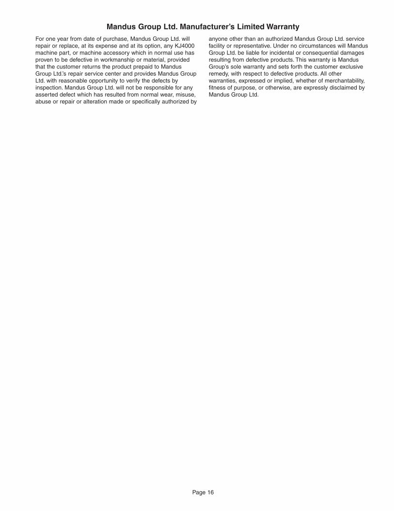

![eConveyancing Operating Requirements · [ 4"]" Operating Requirements 1. Preliminary These Operating Requirements constitute the Operating Requirements determined by the Registrar](https://img.pdfslide.net/doc/110x75/6068afe4cca44b21d4261c59/econveyancing-operating-requirements-4-operating-requirements-1.jpg)