Embed Size (px)
Citation preview

KLIC-DD
KNX – Residential A/C Unit Interface
ZN1CL-KLIC-DD U
SE
R M
AN
UA
L
Application program version: [1.5]
User manual edition: [1.5]_c
www.zennio.com

KLIC-DD
http://www.zennio.com Technical Support: http://support.zennio.com
2
CONTENIDO
Contenido ...................................................................................................................................... 2
Document updates ........................................................................................................................ 3
1 Introduction .......................................................................................................................... 4
1.1 KLIC-DD .......................................................................................................................... 4
1.2 Installation ..................................................................................................................... 5
2 Configuration......................................................................................................................... 7
2.1 Basic control .................................................................................................................. 7
2.2 Advanced functionalities ............................................................................................... 7
3 ETS Parameterizacion .......................................................................................................... 10
3.1 Default configuration .................................................................................................. 10
3.2 General window .......................................................................................................... 12
3.2.1 Device model ................................................................................................... 12
3.2.2 Scenes .............................................................................................................. 12
3.2.3 Temperature limitation ................................................................................... 14
3.2.4 Auto OFF .......................................................................................................... 15
3.2.5 Errors Management ........................................................................................ 15
3.2.6 Start-up configuration ..................................................................................... 16
3.2.7 Advanced climate management...................................................................... 18
3.2.8 Logical functions .............................................................................................. 20
3.3 Mode window ............................................................................................................. 21
3.4 Fan window ................................................................................................................. 22
ANNEX I. Communication objects ............................................................................................... 24
ANNEX II. Correspondence with A/C unit error codes ................................................................ 27

KLIC-DD
http://www.zennio.com Technical Support: http://support.zennio.com
3
DOCUMENT UPDATES
Version Changes Page(s)
[1.5]_c Minor text corrections. -
[1.5]_b
Enlarging the explanation of the Advanced Climate Management.
-
Minor text corrections. -
KLIC-DD
http://www.zennio.com Technical Support: http://support.zennio.com
4
1 INTRODUCTION
1.1 KLIC-DD
KLIC-DD is a Zennio interface that allows bidirectional communication between a KNX
domotic system and residential air-conditioning units.
Due to its bidirectional communication, the air conditioning unit can be controlled in the
same way as using a remote control and the real status of the air-conditioning unit is
checked and sent to the KNX bus for its monitoring.
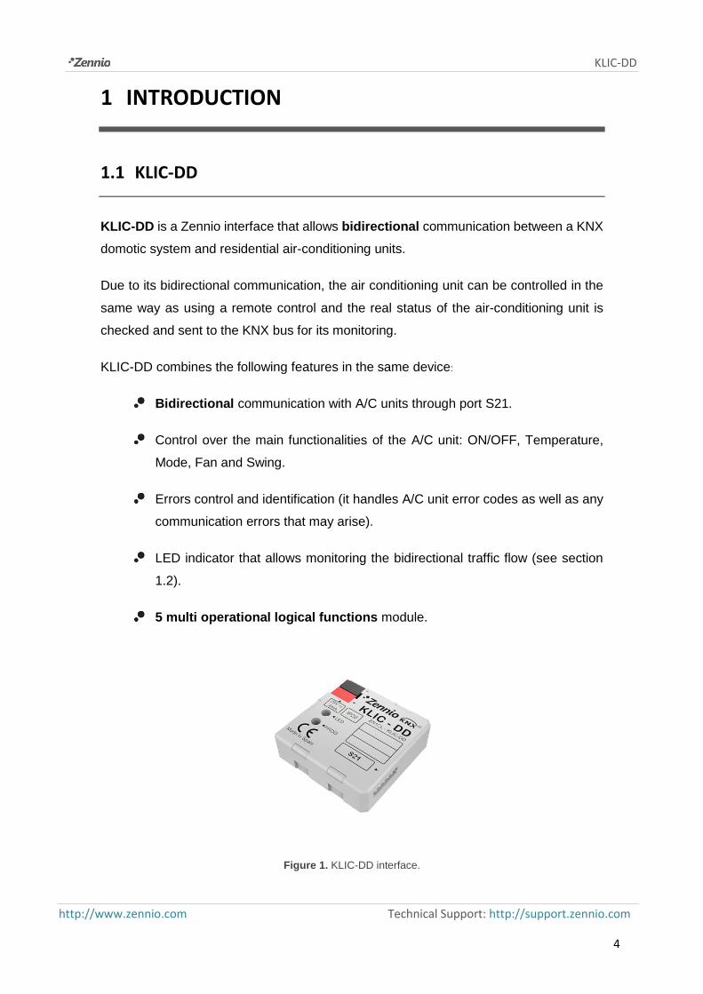
KLIC-DD combines the following features in the same device:
Bidirectional communication with A/C units through port S21.
Control over the main functionalities of the A/C unit: ON/OFF, Temperature,
Mode, Fan and Swing.
Errors control and identification (it handles A/C unit error codes as well as any
communication errors that may arise).
LED indicator that allows monitoring the bidirectional traffic flow (see section
1.2).
5 multi operational logical functions module.
Figure 1. KLIC-DD interface.

KLIC-DD
http://www.zennio.com Technical Support: http://support.zennio.com
5
1.2 INSTALLATION
KLIC-DD interface connects to the KNX bus via the bus connecting terminals (1).
On the other hand, this device is connected to the internal unit PCB, using a special 5-
wire cable with S21 connectors provided in the original device packaging (4).
Once the device is provided with power supply from the KNX bus, both the physical
address and the associated application program can be downloaded.
In the Figure 2, the elements scheme of KLIC-DD is shown.
Figure 2. KLIC-DD Elements scheme.
It is described below the functionality of its main elements:
Programming button (3): a short press on this button set the device in
programming mode, and the associated LED (2) lights red. If this button is held
while plugging the device into de KNX bus, KLIC-DD goes into secure mode.
LED indicator (2): luminous signal that indicates the working state of KLIC-
DD. Besides lighting red when the device is in programming mode, this LED
will also light blue and green, thus indicating the status of the bidirectional
communication between KNX and the A/C unit, resulting very useful in the
installation process. Next, the meaning of each LED color is explained:
➢ Fixed red: KLIC-DD is in programming mode.
1.- KNX connector
2.- LED indicator
3.- Programming button
4.- S21 communication cable

KLIC-DD
http://www.zennio.com Technical Support: http://support.zennio.com
6
➢ Blinking red: KLIC-DD is in secure mode (the LED blinks red every 0.5
seconds).
➢ Blinking green: communication data from A/C unit to KLIC-DD.
➢ Blinking blue: communication data from KLIC-DD to A/C unit.
Communication cable: 5-wire cable to connect KLIC-DD to the PCB board
(S21) of the inner unit of the A/C unit.
To obtain more detailed information about the technical features of KLIC-DD, as well as
security and installation information, please read the controller Datasheet, included in
the original package of the device and also available at http://www.zennio.com.
It is also recommended to consult the KLIC-DD Installation Note, available in the same
web site.

KLIC-DD
http://www.zennio.com Technical Support: http://support.zennio.com
7
2 CONFIGURATION
2.1 BASIC CONTROL
With KLIC-DD, the air-conditioning unit can be monitored and controlled the same way
it is done with the infrared remote control provided with it.
By means of the KNX bus, the following basic functionalities of the air conditioning unit
can be controlled:
ON/OFF
Setpoint Temperature
Operating mode: Auto, Heat, Cool, Fan and Dry.
Fan Speed: 3 or 5 speed levels configuration, besides the automatic speed
(check out the available levels in the A/C unit)
Swing: swing or stopped
These functionalities have associated a machine status, which is periodically sent to
KLIC-DD. When KLIC-DD receives a status different from the previous one from the
machine, it updates the status of the corresponding parameter in the KNX bus.
2.2 ADVANCED FUNCTIONALITIES
Besides the basic control over the air-conditioning system, KLIC-DD offers other
advanced functionalities that give an added value to the remote control:
Scenes configuration: allows establishing a specific parameters combination
and its synchronized sending to the machine, in order to generate a specific
climate ambient in the room. KLIC-DD allows configuring up to 4 different
scenes.

KLIC-DD
http://www.zennio.com Technical Support: http://support.zennio.com
8
Temperature limitation: A/C units are limited in temperature for each
operating mode by default. This functionality allows configuring custom
temperature ranges, via parameter, in such way that the setpoint temperature
will remain in that range. In case of receiving from the KNX bus a temperature
command with a value out of the configured limits, the temperature value sent
to the machine will be the corresponding limit value.
Auto OFF: allows an automatic and temporary switch off of the machine (after
an established delay, if parameterized) if a status change in the communication
object associated to it takes place. Moreover, it has an option called "Flexibility
enabled" that allows, if it is enabled, reactivating the unit although it is in the
auto off.
An example of this functionality could be the use of a window sensor,
associated to the auto switch off, which allows switching off the machine if the
window is opened.
Errors management: this functionality allows sending messages to the KNX
bus informing about errors. Errors management handles A/C unit error codes
as well as any communication errors that may arise.
Besides informing about the apparition of possible errors it can be also
configured the sending of the error type. In case of internal errors, the numerical
code associated to the error type is shown in Table 1.
Regarding the numerical code associated to the type of external errors, please
look up the manual of the installed air-conditioning system.
Error Number Type of Internal Error
1 Problems with the data reception (speed,
parity, etc.)
2 Communication waiting time exceeded
(Time Out)
3 Incorrect checksum
4 Incorrect response from the machine
Table 1. Type of Internal Error.

KLIC-DD
http://www.zennio.com Technical Support: http://support.zennio.com
9
Initial configuration: this functionality allows establishing an initial value for
the A/C unit statuses after installing the system or after recovering from a power
failure. The statuses that may be configured are: ON/OFF, temperature, mode,
fan and swing of the machine.
This initial configuration can be sent both to the KNX bus and to the A/C unit.
Advanced Climate Management: it allows modifying the setpoint temperature
to be sent to the A/C unit according to the current temperature of the room to
climate (temperature measured by an external sensor, as the touch panel
InZennio Z38i). The advanced climate management is useful when the
temperature measured by the external sensor is different than the measured
by the A/C unit. The reference for the user is the temperature of the external
sensor and, sometimes, it does not reach the setpoint temperature.
This functionality consists on a periodical analysis of the difference between
the current temperature and the setpoint temperature. If KLIC-DD detects a
more than 1ºC difference between them, it will readjust the setpoint
temperature value adding it the difference with current temperature. KLIC-DD
keeps a memory of these possible deviations, in order to apply them again after
a reset, change of mode, etc.
Logical functions: KLIC-DD allows enabling and configuring up to 5 different
logical functions. Please read section 3.2.8 for further information.

KLIC-DD
http://www.zennio.com Technical Support: http://support.zennio.com
10
3 ETS PARAMETERIZACION
For starting to parameterize the KLIC-DD interface it is necessary, once the ETS
program has been opened, importing the data base of the product (version 1.5 of the
application program).
Next, the device is added to the project. The configuration process begins by entering
the Parameters tab of the device.
In the following sections there is a detailed explanation about each of the different
functionalities of KLIC-DD in ETS.
3.1 DEFAULT CONFIGURATION
This section shows the default configuration from which the device parameterization
starts.
Figure 3. Default topology in KLIC-DD.
In the default topology window (see Figure 3) appear the communication objects
associated to the sending and reception of the orders for basic control of the A/C unit:
ON/OFF, Temperature, Mode, Fan and Swing.
When entering for the first time to the parameters edition of KLIC-DD, the following
window will be shown:
KLIC-DD
http://www.zennio.com Technical Support: http://support.zennio.com
11
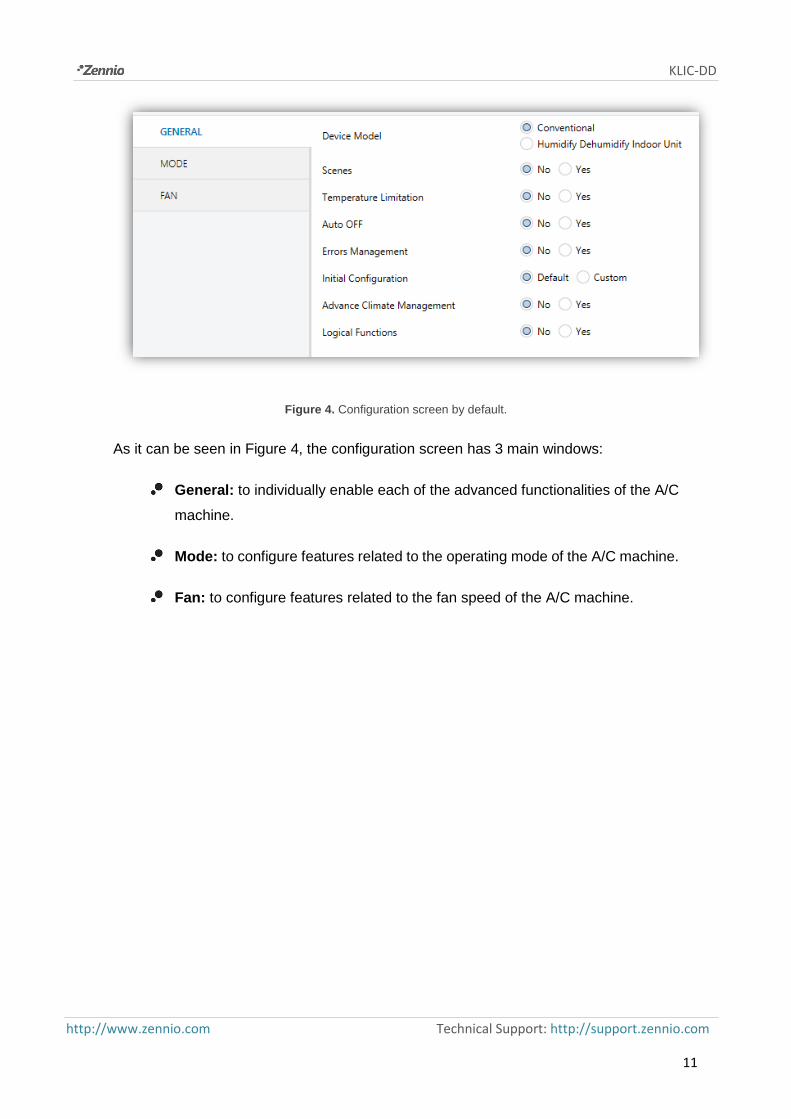
Figure 4. Configuration screen by default.
As it can be seen in Figure 4, the configuration screen has 3 main windows:
General: to individually enable each of the advanced functionalities of the A/C
machine.
Mode: to configure features related to the operating mode of the A/C machine.
Fan: to configure features related to the fan speed of the A/C machine.

KLIC-DD
http://www.zennio.com Technical Support: http://support.zennio.com
12
3.2 GENERAL WINDOW
From the general configuration window the different advanced functionalities of the A/C
unit can be enabled (Scenes, Temperature Limitation, Auto OFF, Errors Management,
Initial Configuration, Advance Climate Management and Logical Functions), as well as
the A/C unit model to control (conventional or Humidify Dehumidify Indoor Unit). All these
advanced functionalities are explained in detail in the following sections.
3.2.1 DEVICE MODEL
This option allows selecting the A/C model to control, choosing between: Conventional
model or Humidify Dehumidify Indoor Unit.
The conventional model includes all the A/C residential machines compatible with the
KLIC-DD interface.
If the second option is chosen, it will appear several communication objects related to
the specific functionality of this A/C model. Moreover, during all the parameterization,
several options with regard to this model will be shown (named in ETS as *Humidify
Dehumidify Indoor Unit).
3.2.2 SCENES
After enabling this functionality, it will appear in the left menu the option Scenes, where
to enable and parameterise each of the 4 available scenes. The scene to be run will be
sent to the KNX bus through the object, enabled for this aim: "Scenes".
Figure 5. Scenes configuration window.

KLIC-DD
http://www.zennio.com Technical Support: http://support.zennio.com
13
For every enabled scene, the parameters that may be configured are the following:
Scene number. It indicates the scene number (from 1 to 64) to which the
corresponding configured orders will be sent to the A/C machine.
ON/OFF. Possibility to choose the A/C machine status: No change, OFF or ON.
Temperature. No change or sending of a new temperature value (from 18ºC
to 30ºC).
Mode. No change, auto, heat, dry, fan, cool or humidify (only for Humidify
Dehumidify models).
Fan. No change, auto, minimum, medium, maximum.
Swing. No change, both stopped, normal swing. And the options for Humidify
Dehumidify Indoor Units: Extra swing or both swing.
In the Figure 6, an example of scene configuration is shown.
Figure 6. Scene configuration example (Scene 1).

KLIC-DD
http://www.zennio.com Technical Support: http://support.zennio.com
14
3.2.3 TEMPERATURE LIMITATION
The air conditioning unit has defined upper and lower temperature limits that cannot be
exceeded. Nevertheless, KLIC-DD offers the possibility of establishing new temperature
limits if they are specified within the A/C unit predefined limits (please, llok up the A/C
unit manual).
Temperature limits can be customized for the three modes that have a temperature
associated: Auto, Cool and Heat.
Figure 7: Temperature limitation configuration.
For these limits to be taken into account, it will be necessary to explicitly enable the
temperature limitation, by sending the value "1" through the specific communication
object "Temperature Limitation". To control the machine using its predefined temperature
limitations, it is necessary to send the value "0" through the same object.
Once established the new temperature limits for every mode and enabled the
functionality, when a value out of the range is sent from the KNX bus, the value that will
be sent to the A/C unit will be the corresponding temperature limit and this new
temperature will be notified, through the object "Temperature sending".
Note: When configuring in ETS the temperature limitation, this functionality is
automatically enabled by default and the personalized ranges will control the unit
performance when it switches on.

KLIC-DD
http://www.zennio.com Technical Support: http://support.zennio.com
15
3.2.4 AUTO OFF
This option allows switching off the A/C machine temporarily if a status change (from
value "0" to value "1") in the associated communication object happens ("Auto-OFF").
Figure 8. Auto OFF configuration.
The following parameters can be configured:
Delay for Auto-OFF: to establish the time, in seconds, KLIC-DD waits before
automatically switching off the A/C machine.
Flexibility enabled?: when enabling this parameter ("Yes"), it will be possible
to restore the unit control although it is in auto off mode: ("Auto-OFF"=1). If this
option is disabled, the unit cannot be controlled after an auto-off order and it
will remain inactive until the object "Auto-OFF" has the value "0".
3.2.5 ERRORS MANAGEMENT
The errors management window allows enabling sending messages to the bus indicating
any error that may arise: internal errors of the communication between KLIC-DD and the
A/C unit, or external errors (errors in the own A/C unit).
Figure 9. Errors management configuration window.
The detection of internal, external or both types of errors can be enabled:

KLIC-DD
http://www.zennio.com Technical Support: http://support.zennio.com
16
Internal errors: when enabling this option, two new communication objects
appear: "Internal error", 1-bit object and "Type of internal error", 1-byte object.
The first one indicates if an internal error has occurred (value "1": there is an
error, value "0": there is not). The second object indicates the code that
identifies the error (numerical value between 1 and 4. See Table 1. Type of
Internal Error.).
External errors: when enabling this option, two new communication objects
appear: "External Error" and "Type of external error". The first one indicates if
an external error has occurred (value "1": there is an error, value "0": there is
not). The second object indicates the code that identifies the error (see the
specific manual of the A/C unit installed).
3.2.6 START-UP CONFIGURATION
This functionality allows configuring the initial statuses of the A/C machine after the
installation or a power failure. This configuration can be default or custom. If a custom
configuration is chosen, the window of the Figure 10 will be shown.
Figure 10. Initial configuration window.
The variables than can be initialized are the following:
ON/OFF: last (the status the machine had before the power failure; after the
first installation, this status will be OFF), ON or OFF.
Temperature: Last or custom (a new field appears to establish the new initial
temperature).

KLIC-DD
http://www.zennio.com Technical Support: http://support.zennio.com
17
Mode: Last, auto, heat, dry, fan, cool or humidify (only for Humidify Dehumidify
models).
Fan: Last, auto, minimum, medium or maximum.
Swing: Last, both stopped, normal swing. And the options for Humidify
Dehumidify Indoor Units: Extra swing or both swing.
Moreover, it can be configured the sending of the statuses to the KNX bus and/or to the
A/C split and when they must be carried out:
Send initial configuration to BUS?: If this sending is enabled ("Yes"), a new
field will appear next: "Delay", where to configure the time, in seconds, KLIC-
DD delays the sending of the statuses to the KNX bus.
Send initial configuration to SPLIT?: If this sending is enabled ("Yes"), a new
field will appear next: "Delay", where to configure the time, in seconds, KLIC-
DD delays the sending of the statuses to the A/C machine.
Note: It is highly recommended to establish a delay for the initial configuration sending
to split of at least 1 minute, in order to leave the machine enough time for recovering
itself after a power failure. It is also recommended to establish a higher delay for the
initial configuration sending to the Bus than for the Split. If not, the values could be sent
to the bus twice: the first one, due to the initial statuses sending to the Bus and other due
to a response to the initial configuration to the Split from the split itself.

KLIC-DD
http://www.zennio.com Technical Support: http://support.zennio.com
18
3.2.7 ADVANCED CLIMATE MANAGEMENT
This functionality allows modifying the setpoint temperature sent to the A/C machine,
with regard to the real temperature of the room to be climate, measured by an external
KNX sensor.
Figure 11. Advance climate management.
The real temperature monitoring is carried out in some periods of time. This analyse
period is configured in the ACM window (Advance Climate Management) in the Analyze
Period field, where the monitoring period should be set in minutes, depending on the
particular conditions of the installation where the A/C unit is located. It is possible to set
periods between 15 and 240 minutes (take into account that the value set in the field
“Analyze period” is internally multiplied by 5, so the allowed range of values is [3-48]).
When enabling this option, two communication objects appear (2-bytes each): "Ambient
Temperature" and "Modified Temperature". The first one receives the value of the current
temperature of the room (this value must be periodically sent by an external KNX
sensor). The second object indicates the setpoint temperature that is sent to the
machine, modified according to the original as indicated next.
The behaviour of this functionality is as follows:
If the ambient temperature is not stable during the analyze period (more than
1ºC variation), KLIC-DD continues monitoring.
If the ambient temperature is stable during the analyze period (maximum
variation 1ºC), KLIC-DD considers that this is the temperature that the indoor
unit will reach with the current setpoint. In this case, this temperature is
compared with the setpoint temperature and, if there is a difference greater
than 1ºC, the setpoint temperature is adjusted by calculating a new modified
setpoint temperature. The new setpoint is sent through the communication

KLIC-DD
http://www.zennio.com Technical Support: http://support.zennio.com
19
object “Modified temperature”. The calculation of the new modified temperature
is obtained applying the next formula:
➢ After download or after a user setpoint change (first calculation):
𝑇𝑚𝑜𝑑. = 𝑇 + (𝑇 − 𝑇𝑟𝑜𝑜𝑚)
➢ Once the first calculation is done, to achieve a more precise adjustment:
𝑇𝑚𝑜𝑑. = 𝑇 + 𝑇𝑚𝑜𝑑. 𝑝𝑟𝑒𝑣𝑖𝑜𝑢𝑠
2+ (
𝑇 + 𝑇𝑚𝑜𝑑.𝑝𝑟𝑒𝑣𝑖𝑜𝑢𝑠
2− 𝑇𝑟𝑜𝑜𝑚)
Where “Tmod.” is the modified temperature; “T”, user setpoint; “Troom”, room
temperature sent by an external sensor and “Tmod previous”, the previous
modified temperature calculated.
Important: Since room temperature is used in modified temperature calculation, this
value must be periodically received in order to have an appropriated behaviour of the
advanced climate management.
Examples:
Setpoint upper than room temperature: if the current room temperature stays
constant to 22ºC during the analyze period and setpoint is equal to 25ºC, the “Modified
Temperature” that will be sent to the A/C machine is: 25 + (25 − 22) = 28ºC.
If during the next analyze period, the room temperature has not reached user setpoint
yet, and stays constant to 23ºC, the “Modified Temperature” that will be sent to the A/C
machine is: 25+28
2+ (
25+28
2− 23) = 28,5ºC
A new modified temperature will be successively calculated until room temperature does
not differ from user setpoint more than 1ºC.
Setpoint lower than room temperature: if the current room temperature stays
constant to 26ºC during the analyze period and setpoint is equal to 24ºC, the “Modified
Temperature” that will be sent to the A/C machine is: 24 + (24 − 26) = 22ºC.
Modified temperature will be successively recalculated until room temperature does not
differ from user setpoint more than 1ºC.

KLIC-DD
http://www.zennio.com Technical Support: http://support.zennio.com
20
It is advisable not to show the object “Modified Temperature” as indicator since this
advanced climate management must be transparent to the user. For this reason, the
object “Temperature Reception” always indicates the temperature sent through the
“Temperature Sending” object.
3.2.8 LOGICAL FUNCTIONS
This module makes it possible to perform numeric and binary operations to incoming
values received from KNX bus, and to send the results through other communication
objects specifically enabled for this purpose.
KLIC-DD can implement up to 5 different and independent functions, each of them
entirely customisable and consisting in up to 4 consecutive operations each one.
The execution of each function can depend on a configurable condition, which will be
evaluated every time the function is triggered through specific, parameterizable
communication objects. The result after executing the operations of the function can also
be evaluated according to certain conditions and afterwards sent (or not) to the KNX
bus, which can be done every time the function is executed, periodically or only when
the results differs from the last one.
Please refer to the “Logic Functions” user manual (available within the KLIC-DD
product section at the Zennio homepage: www.zennio.com) for detailed information
about the functionality and the configuration of the related parameters.

KLIC-DD
http://www.zennio.com Technical Support: http://support.zennio.com
21
3.3 MODE WINDOW
As seen in section 3.1. Default configuration, the specific Mode window allows
configuring featured regarding to the operating mode of the A/C machine.
Figure 12. Mode window.
Individual modes: when selecting this option, 10 new 1-bit communication
objects will be shown. 5 of them are associated to the sending of each of the
available modes (Auto, Cool, Fan, Heat and Dry) and the other 5 objects, to
the reception from the A/C machine of the status of every mode.
The objects associated with the sending are: "Auto Mode Sending", "Cool
Mode Sending", "Fan Mode Sending", "Heat Mode Sending" and "Dry Mode
Sending".
The objects associated to the reception are: "Auto Mode Reception", "Cool
Mode Reception", "Fan Mode Reception", "Heat Mode Reception" and "Dry
Mode Reception".
Moreover, the objects "Mode Sending" and "Mode Reception" (1-byte each and
available by default) may be used.
If the option Individual modes is activated, the operating mode of the A/C
machine can be modified (by writing the value "1" through the sending object
associated to the desired individual mode). Moreover, the current mode will be
also sent to the KNX bus, through the object "Mode Reception" and with the 1-
bit reception object of the individual current mode.
Simplified modes: when selecting this option, the 1-bit object "Simplified
Mode" will be enabled. It allows establishing the desired mode: Cool mode,
writing the value "0" in the object, or Heat mode, writing the value "1". For this
control object there is no status object associated.

KLIC-DD
http://www.zennio.com Technical Support: http://support.zennio.com
22
3.4 FAN WINDOW
In this window it can be configured several features related to the fan speed of the A/C
machine.
Figure 13. Fan window.
Number of levels: this option allows configuring the number of fan levels the
A/C unit has. These may be 3 or 5 levels. The fan speed has associated two
1-byte objects: "Fan [1 Byte] Sending" and "Fan Reception", for controlling and
indicating the fan speed when requested. The control object ("Fan Sending")
records the fan speed in percentage. This value will be interpolated in such a
way that corresponds to the selected number of levels, as it can be seen next.
The status object ("Fan Reception") will show the current fan sped, according
to the interpolated percentages.
➢ 3 levels: The fan speed percentages will be interpolated as shown in Table
2.
Initial Speed
Percentage
Interpolated Speed
Percentage
Level
0% 0% Auto
1-20% 20% Minimum
21-60% 60% Medium
61-100% 100% Maximum
Table 2. Fan speed percentages for 3 levels.

KLIC-DD
http://www.zennio.com Technical Support: http://support.zennio.com
23
➢ 5 levels: The fan speed percentages will be interpolated as shown in Table
3.
Initial Speed
Percentage
Interpolated Speed
Percentage
Level
0% 0% Auto
1-20% 20% Minimum
21-40% 40% Minimum-
Medium
41-60% 60% Medium
61-80% 80% Medium-
Maximum
81-100% 100% Maximum
Table 3. Fan speed percentages for 5 levels.
Step control: the selection of this option ("Yes") enables the 1-bit object "Fan
[1 bit] Sending" that allows increasing (sending the value "1") or decreasing
(value "0") the fan speed in one level (for example, for 3 levels, in the minimum
level of fan speed, the value "1" is sent via the object "Fan [1 bit] Sending", the
fan speed level will go to medium).
The step control is not cyclical. This means that, being in the Auto level (0%),
when decreasing the fan speed level, the A/C machine will stay in the auto
mode until the speed level is increased. The same way, when the speed level
is in the maximum level (100%), the machine will remain in this level until
receiving an order to decrease the speed.

KLIC-DD
http://www.zennio.com Technical Support: http://support.zennio.com
24
ANNEX I. COMMUNICATION OBJECTS
“Functional range” shows the values that, with independence of any other values permitted by the bus according to the object size, may be of any use or have a particular meaning
because of the specifications or restrictions from both the KNX standard or the application program itself.
Number Size I/O Flags Data Type (DPT) Functional Range Name Function 0 1 Bit I C - - W U DPT_Switch 0/1 On/Off Sending Turn ON/OFF the split
1 2 Bytes I C - - W U DPT_Value_Temp 16ºC – 32ºC or ac. to param. Temperature Sending Value sent to the Split
2 1 Byte I C - - W U DPT_HVACContrMode
0 = Auto 1 = Heat 3 = Cool 9 = Fan 14 = Dry
Mode Sending 0=Aut,1=Ht,3=Cool,9=Fan,14=Dry
3 1 Byte I C - - W U DPT_Scaling 0% - 100% Fan [1byte] Sending 0%Au,1-20%Mi,21-40%Mi/Mid,...
(5 levels)
1 Byte I C T - W U DPT_Scaling 0% - 100% Fan [1byte] Sending 0%Aut,1-20%Min,21-60%Mid,>60Ma (3 levels)
4 1 Bit I C - - W U DPT_Switch 0/1 Swing Sending 0=Stop/Step; 1=Swing 5 1 Bit O C T R - - DPT_Switch 0/1 On/Off Reception Split State (ON/OFF)
6 2 Bytes O C T R - - DPT_Value_Temp 16ºC – 32ºC or ac. to param. Temperature Reception Value received from the Split
7 1 Byte O C T R - - DPT_HVACContrMode
0 = Auto 1 = Heat 3 = Cool 9 = Fan 14 = Dry
Mode Reception Actual Mode:0=Auto,1=Heat...
8 1 Byte O C T R - - DPT_Scaling 0% - 100% Fan Reception 0%Aut,20%Min,60%Mid,100%Max
(3 levels)
1 Byte O C T R - - DPT_Scaling 0% - 100% Fan Reception 0%Aut,20%Mi,40%Mi/Mid,60%Mid.. (5 levels)
9 1 Bit O C T R - - DPT_Switch 0/1 Swing Reception Swing Status:0=Stopped,1=Swing 10 1 Bit I C T - W U DPT_Switch 0/1 Auto Mode Sending 1=Set Auto Mode;0=Nothing 11 1 Bit I C T - W U DPT_Switch 0/1 Cool Mode Sending 1=Set Cool Mode;0=Nothing 12 1 Bit I C T - W U DPT_Switch 0/1 Heat Mode Sending 1=Set Heat Mode;0=Nothing

KLIC-DD
http://www.zennio.com Technical Support: http://support.zennio.com
25
13 1 Bit I C T - W U DPT_Switch 0/1 Fan Mode Sending 1=Set Fan Mode;0=Nothing 14 1 Bit I C T - W U DPT_Switch 0/1 Dry Mode Sending 1=Set Dry Mode;0=Nothing 15 1 Bit I C - - W U DPT_Heat_Cool 0/1 Simplified Mode 0=Cool; 1=Heat 16 1 Bit O C T R - - DPT_Switch 0/1 Auto Mode Reception 1=Auto Mode Enabled;0=Disabled 17 1 Bit O C T R - - DPT_Switch 0/1 Cool Mode Reception 1=Cool Mode Enabled;0=Disabled 18 1 Bit O C T R - - DPT_Switch 0/1 Heat Mode Reception 1=Heat Mode Enabled;0=Disabled 19 1 Bit O C T R - - DPT_Switch 0/1 Fan Mode Reception 1=Fan Mode Enabled;0=Disabled 20 1 Bit O C T R - - DPT_Switch 0/1 Dry Mode Reception 1=Dry Mode Enabled;0=Disabled 21 1 Bit I C - - W U DPT_Step 0/1 Fan [1 bit] Sending 0=Down;1=Up 22 1 Byte I C - - W U DPT_SceneControl 0-63; 128-191 Scenes Set Scene "Value" 23 1 Bit I/O C T R W U DPT_Switch 0/1 Temperature Limitation 0=Disable;1=Enable 24 1 Bit I C - - W U DPT_Switch 0/1 Auto-OFF 0=Disable;1=Enable 25 1 Bit O C T R - - DPT_Switch 0/1 Internal Error 0=No Error; 1=Error 26 1 Byte O C T R - - - 1-4 Type of Internal Error 1=Recep.Err,2=TimeOut,3=Che... 27 1 Bit O C T R - - DPT_Switch 0/1 External Error 0=No Error; 1=Error 28 1 Byte O C T R - - - 0-255 Type of External Error Check Errors Table 29 1 Bit I C - - W U DPT_Switch 0/1 Humidify Mode Sending 1=Enable Mode,0=Ignore 30 1 Bit O C T R - - DPT_Bool 0/1 Humidify Mode Reception 0=Disabled,1=Enabled 31 1 Byte O C T R - - DPT_Scaling 0% - 100% Humidify Level Reception 0=Off,25=Low,50=Med,75=Hi... 32 1 Bit I C - - W U DPT_Switch 0/1 Humidify Level Step Sending 0=Down,1=Up 33 1 Bit I C - - W U DPT_Switch 0/1 Extra Swing Sending 0=Stop,1=Move 34 1 Bit O C T R - - DPT_Switch 0/1 Extra Swing Reception 0=Stopped,1=Movement 35 2 Bytes I C - - W U DPT_Value_Temp 16ºC – 32ºC Ambient Temperature Temperature from KNX 36 2 Bytes O C T R - - DPT_Value_Temp 16ºC – 32ºC Modified Temperature Real Temp. Sent to Machine 37 1 Bit I C - - W - DPT_Bool 0/1 [LF] (1 bit) Data Entry 1 Binary Data Entry (0/1) 38 1 Bit I C - - W - DPT_Bool 0/1 [LF] (1 bit) Data Entry 2 Binary Data Entry (0/1) 39 1 Bit I C - - W - DPT_Bool 0/1 [LF] (1 bit) Data Entry 3 Binary Data Entry (0/1) 40 1 Bit I C - - W - DPT_Bool 0/1 [LF] (1 bit) Data Entry 4 Binary Data Entry (0/1) 41 1 Bit I C - - W - DPT_Bool 0/1 [LF] (1 bit) Data Entry 5 Binary Data Entry (0/1) 42 1 Bit I C - - W - DPT_Bool 0/1 [LF] (1 bit) Data Entry 6 Binary Data Entry (0/1) 43 1 Bit I C - - W - DPT_Bool 0/1 [LF] (1 bit) Data Entry 7 Binary Data Entry (0/1) 44 1 Bit I C - - W - DPT_Bool 0/1 [LF] (1 bit) Data Entry 8 Binary Data Entry (0/1) 45 1 Bit I C - - W - DPT_Bool 0/1 [LF] (1 bit) Data Entry 9 Binary Data Entry (0/1) 46 1 Bit I C - - W - DPT_Bool 0/1 [LF] (1 bit) Data Entry 10 Binary Data Entry (0/1) 47 1 Bit I C - - W - DPT_Bool 0/1 [LF] (1 bit) Data Entry 11 Binary Data Entry (0/1) 48 1 Bit I C - - W - DPT_Bool 0/1 [LF] (1 bit) Data Entry 12 Binary Data Entry (0/1) 49 1 Bit I C - - W - DPT_Bool 0/1 [LF] (1 bit) Data Entry 13 Binary Data Entry (0/1)

KLIC-DD
http://www.zennio.com Technical Support: http://support.zennio.com
26
50 1 Bit I C - - W - DPT_Bool 0/1 [LF] (1 bit) Data Entry 14 Binary Data Entry (0/1) 51 1 Bit I C - - W - DPT_Bool 0/1 [LF] (1 bit) Data Entry 15 Binary Data Entry (0/1) 52 1 Bit I C - - W - DPT_Bool 0/1 [LF] (1 bit) Data Entry 16 Binary Data Entry (0/1) 53 1 Byte I C - - W - DPT_Value_1_Ucount 0 - 255 [LF] (1 byte) Data Entry 1 1 byte Data Entry (0-255) 54 1 Byte I C - - W - DPT_Value_1_Ucount 0 - 255 [LF] (1 byte) Data Entry 2 1 byte Data Entry (0-255) 55 1 Byte I C - - W - DPT_Value_1_Ucount 0 - 255 [LF] (1 byte) Data Entry 3 1 byte Data Entry (0-255) 56 1 Byte I C - - W - DPT_Value_1_Ucount 0 - 255 [LF] (1 byte) Data Entry 4 1 byte Data Entry (0-255) 57 1 Byte I C - - W - DPT_Value_1_Ucount 0 - 255 [LF] (1 byte) Data Entry 5 1 byte Data Entry (0-255) 58 1 Byte I C - - W - DPT_Value_1_Ucount 0 - 255 [LF] (1 byte) Data Entry 6 1 byte Data Entry (0-255) 59 1 Byte I C - - W - DPT_Value_1_Ucount 0 - 255 [LF] (1 byte) Data Entry 7 1 byte Data Entry (0-255) 60 1 Byte I C - - W - DPT_Value_1_Ucount 0 - 255 [LF] (1 byte) Data Entry 8 1 byte Data Entry (0-255) 61 2 Bytes I C - - W - DPT_Value_2_Count 0 - FFFF [LF] (2 bytes) Data Entry 1 2 bytes Data Entry 62 2 Bytes I C - - W - DPT_Value_2_Count 0 - FFFF [LF] (2 bytes) Data Entry 2 2 bytes Data Entry 63 2 Bytes I C - - W - DPT_Value_2_Count 0 - FFFF [LF] (2 bytes) Data Entry 3 2 bytes Data Entry 64 2 Bytes I C - - W - DPT_Value_2_Count 0 - FFFF [LF] (2 bytes) Data Entry 4 2 bytes Data Entry 65 2 Bytes I C - - W - DPT_Value_2_Count 0 - FFFF [LF] (2 bytes) Data Entry 5 2 bytes Data Entry 66 2 Bytes I C - - W - DPT_Value_2_Count 0 - FFFF [LF] (2 bytes) Data Entry 6 2 bytes Data Entry 67 2 Bytes I C - - W - DPT_Value_2_Count 0 - FFFF [LF] (2 bytes) Data Entry 7 2 bytes Data Entry 68 2 Bytes I C - - W - DPT_Value_2_Count 0 - FFFF [LF] (2 bytes) Data Entry 8 2 bytes Data Entry 69 1 Bit O C T R - - DPT_Bool 0/1 [LF] Function 1 RESULT (1 bit) FUNCTION 1 Result 70 1 Bit O C T R - - DPT_Bool 0/1 [LF] Function 2 RESULT (1 bit) FUNCTION 2 Result 71 1 Bit O C T R - - DPT_Bool 0/1 [LF] Function 3 RESULT (1 bit) FUNCTION 3 Result 72 1 Bit O C T R - - DPT_Bool 0/1 [LF] Function 4 RESULT (1 bit) FUNCTION 4 Result 73 1 Bit O C T R - - DPT_Bool 0/1 [LF] Function 5 RESULT (1 bit) FUNCTION 5 Result 74 1 Byte O C T R - - DPT_Value_1_Ucount 0 - 255 [LF] Function 1 RESULT (1 byte) FUNCTION 1 Result 75 1 Byte O C T R - - DPT_Value_1_Ucount 0 - 255 [LF] Function 2 RESULT (1 byte) FUNCTION 2 Result 76 1 Byte O C T R - - DPT_Value_1_Ucount 0 - 255 [LF] Function 3 RESULT (1 byte) FUNCTION 3 Result 77 1 Byte O C T R - - DPT_Value_1_Ucount 0 - 255 [LF] Function 4 RESULT (1 byte) FUNCTION 4 Result 78 1 Byte O C T R - - DPT_Value_1_Ucount 0 - 255 [LF] Function 5 RESULT (1 byte) FUNCTION 5 Result 79 2 Bytes O C T R - - DPT_Value_2_Count 0 - FFFF [LF] Function 1 RESULT (2 bytes) FUNCTION 1 Result 80 2 Bytes O C T R - - DPT_Value_2_Count 0 - FFFF [LF] Function 2 RESULT (2 bytes) FUNCTION 2 Result 81 2 Bytes O C T R - - DPT_Value_2_Count 0 - FFFF [LF] Function 3 RESULT (2 bytes) FUNCTION 3 Result 82 2 Bytes O C T R - - DPT_Value_2_Count 0 - FFFF [LF] Function 4 RESULT (2 bytes) FUNCTION 4 Result 83 2 Bytes O C T R - - DPT_Value_2_Count 0 - FFFF [LF] Function 5 RESULT (2 bytes) FUNCTION 5 Result

KLIC-DD
http://www.zennio.com Technical Support: http://support.zennio.com
27
ANNEX II. CORRESPONDENCE WITH A/C UNIT ERROR CODES
Correspondence between the error codes (in decimal form) sent to the KNX bus by KLIC-DD and the error codes of the A/C units themselves.
Bus Code Bus Code Bus Code Bus Code Bus Code Bus Code Bus Code Bus Code Bus Code Bus Code
1 1 26 AA 51 E3 76 HC 101 J5 126 LE 151 U7 176 30 201 49 226 62
2 2 27 AH 52 E4 77 HJ 102 J6 127 LF 152 U8 177 31 202 4A 227 63
3 3 28 AC 53 E5 78 HE 103 J7 128 P0 153 U9 178 32 203 4H 228 64
4 4 29 AJ 54 E6 79 HF 104 J8 129 P1 154 UA 179 33 204 4C 229 65
5 5 30 AE 55 E7 80 F0 105 J9 130 P2 155 UH 180 34 205 4J 230 66
6 6 31 AF 56 E8 81 F1 106 JA 131 P3 156 UC 181 35 206 4E 231 67
7 7 32 C0 57 E9 82 F2 107 JH 132 P4 157 UJ 182 36 207 4F 232 68
8 8 33 C1 58 EA 83 F3 108 JC 133 P5 158 UE 183 37 208 50 233 69
9 9 34 C2 59 EH 84 F4 109 JJ 134 P6 159 UF 184 38 209 51 234 6A
10 0A 35 C3 60 EC 85 F5 110 JE 135 P7 160 M0 185 39 210 52 235 6H
11 0H 36 C4 61 EJ 86 F6 111 JF 136 P8 161 M1 186 3A 211 53 236 6C
12 0C 37 C5 62 EE 87 F7 112 L0 137 P9 162 M2 187 3H 212 54 237 6J
13 0J 38 C6 63 EF 88 F8 113 L1 138 PA 163 M3 188 3C 213 55 238 6E
14 0E 39 C7 64 H0 89 F9 114 L2 139 PH 164 M4 189 3J 214 56 239 6F
15 0F 40 C8 65 H1 90 FA 115 L3 140 PC 165 M5 190 3E 215 57 16 A0 41 C9 66 H2 91 FH 116 L4 141 PJ 166 M6 191 3F 216 58 17 A1 42 CA 67 H3 92 FC 117 L5 142 PE 167 M7 192 40 217 59 18 A2 43 CH 68 H4 93 FJ 118 L6 143 PF 168 M8 193 41 218 5A 19 A3 44 CC 69 H5 94 FE 119 L7 144 U0 169 M9 194 42 219 5H 20 A4 45 CJ 70 H6 95 FF 120 L8 145 U1 170 MA 195 43 220 5C 21 A5 46 CE 71 H7 96 J0 121 L9 146 U2 171 MH 196 44 221 5J 22 A6 47 CF 72 H8 97 J1 122 LA 147 U3 172 MC 197 45 222 5E 23 A7 48 E0 73 H9 98 J2 123 LH 148 U4 173 MJ 198 46 223 5F 24 A8 49 E1 74 HA 99 J3 124 LC 149 U5 174 ME 199 47 224 60 25 A9 50 E2 75 HH 100 J4 125 LJ 150 U6 175 MF 200 48 225 61

Join and send us your inquiries about Zennio devices:
http://support.zennio.com
Zennio Avance y Tecnología S.L. C/ Río Jarama, 132. Nave P-8.11 45007 Toledo (Spain).
Tel. +34 925 232 002. www.zennio.com [email protected]