Embed Size (px)
Citation preview

CATALOGUE
KM 12 0316a
CIRCULAR PIPING PARTS Issued: 3/96
THICK WALLED Page: 1
Pages Total: 8 Thick walled circular piping (further as parts) is designated for use only during assembly of ventilation and air conditioning (HVAC) equipment. They are produced in sizes D = 250 to 2500. Working conditions These parts are used in heavy and heavy duty applications where there are extreme temperature and abrasive stress conditions during operation. To size and including models D = 1120 are designed for steel mill operations. From D = 1250, for power engineering. Design The parts are manufactured from steel sheet, with flanges. Access opening are available. Technical information The connection proportions of the flanges are according to PM 12 0505. The shape, description of the parts, sample denotation, main proportions and general weight including the flange (kg) are given in the following tables: A. Pipes - table 1, 2 and 3 B. Elbows - table 4 and 5 C. Pipe elbows - table 6 and 7 D. Transition pipes - table 8 and 9 E. Wye pipes - table 10 and 11. ZVVZ a. s. Tel: 382552728 Sažinova 888 Fax: 382521252 399 25 MILEVSKO e-mail: [email protected]
A. PIPES
Table 1 SHAPES AND DENOTATION OF PIPES
SHAPE DESCRIPTION AND SAMPLE DENOTATION Pipes with two fixed flanges Pipe D - L KM 12 3016.11 Pipe with one fixed flange And one floating flange Pipe D - L KM 12 0316.14 Pipe with two fixed flanges and an access opening *) Pipe D - L KM 12 0316.17 Pipe with one fixed flange, one floating flange and an access opening *) Pipe D - L KM 12 0316.18
*) For size D = 250 the access opening ∅ 125, for D = 280 to 710 ∅ 180, for D = 800 to 2500 - 630 x 400.
Table 2 MAIN PROPORTIONS AND WEIGHTS OF PIPES D = 250 to 560
L *) L *) D t 501 996 1496 1986 996 D t 503 998 1498 998 Weight (kg) Weight (kg)
250 6 20 39 - 72 41 400 6 34 63 93 67 280 23 44 64 - 48 450 38 71 105 75 315 25 48 72 - 52 500 43 80 117 84 355 29 55 81 - 59 560 46 90 131 94
Table 3 MAIN PROPORTIONS AND WEIGHTS FOR D = 630 to 2500
L *) L *) D t 505 1000 1500 3000 1000 D t 505 1000 1500 3000 1000 Weight (kg) Weight (kg)
630 8 73 135 199 - 140 1250 5 115 192 270 505 202 710 82 153 223 - 157 1400 131 218 306 568 227 800 95 174 254 496 184 1600 148 247 346 642 257 900 105 196 286 555 206 1800 169 281 394 731 291 1000 128 228 328 627 238 2000 6 221 365 521 971 375 1120 144 256 367 703 266 2240 246 410 576 1075 420
2500 272 453 636 1185 463 *) see page 3 top
KM 12 0316a - 2 -
* ) in the last column of tables 2 and 3 are given lengths and weights fro designs .17 and .18 (designs .11 and .12 are in other columns).
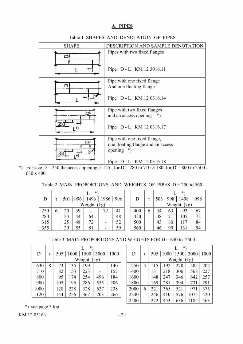
B. ELBOWS
Table 4 SHAPES AND DENOTATION OF ELBOWS
SHAPE DESCRIPTION AND SAMPLE DENOTATION Elbow with two fixed flanges Elbow D / R / α KM 12 0316.11 Elbow with one fixed flange and one floating flange Elbow D / R / α KM 12 0316.14
Table 5 MAIN PROPORTIONS AND WEIGHTS OF ELBOWS
Weight for α Weight for α D R t 30o 60o 90o D R t 30o 60o 90o
250 375 6 9,5 17 24,5 900 900 10 122 227 333 280 420 12 21 31 1000 1000 160 290 420 315 470 14,5 26 38 1120 1120 196 360 524 355 530 18 33 48 1250 1250 6 164 290 415 400 600 8 29 56 82 1400 1400 200 360 495 450 675 36 67 98 1600 1600 250 460 670 500 750 44 83 122 1800 1800 307 562 818 560 840 55 103 152 2000 2000 8 487 908 1330 630 630 10 65 125 180 2240 2240 640 1140 1680 710 710 77 142 209 2500 2500 760 1430 2100 800 800 98 181 265
- 3 - KM 12 0316a
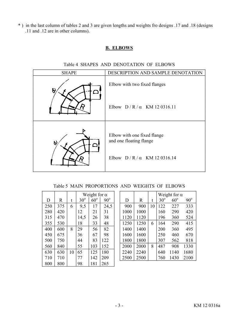
C. PIPE ELBOWS
Table 6 SHAPES AND DENOTATION OF PIPE ELBOWS
SHAPE DESCRIPTION AND SAMPLE DENOTATION Pipe elbow with two fixed flanges Pipe elbow D / R / 15o - L KM 12 0316.31 Pipe elbow with one fixed flange and one floating flange Pipe elbow D / R / 15o - L KM 12 0316.35
Table 7 MAIN PROPORTIONS AND WEIGHTS OF PIPE ELBOWS
D R t L Weight D R t L Weight 250 375 6 897 39 900 900 8 760 196 280 420 886 44 1000 1000 734 228 315 470 873 48 1120 1120 703 256 355 530 856 55 1250 1250 5 668 192 400 600 838 63 1400 1400 628 218 450 675 819 71 1600 1600 576 247 500 750 800 80 1800 1800 523 281 560 840 775 90 2000 2000 6 471 365 630 630 8 830 135 2240 2240 407 410 710 710 810 153 2500 2500 340 453 800 800 786 174
KM 12 0316a - 4 -
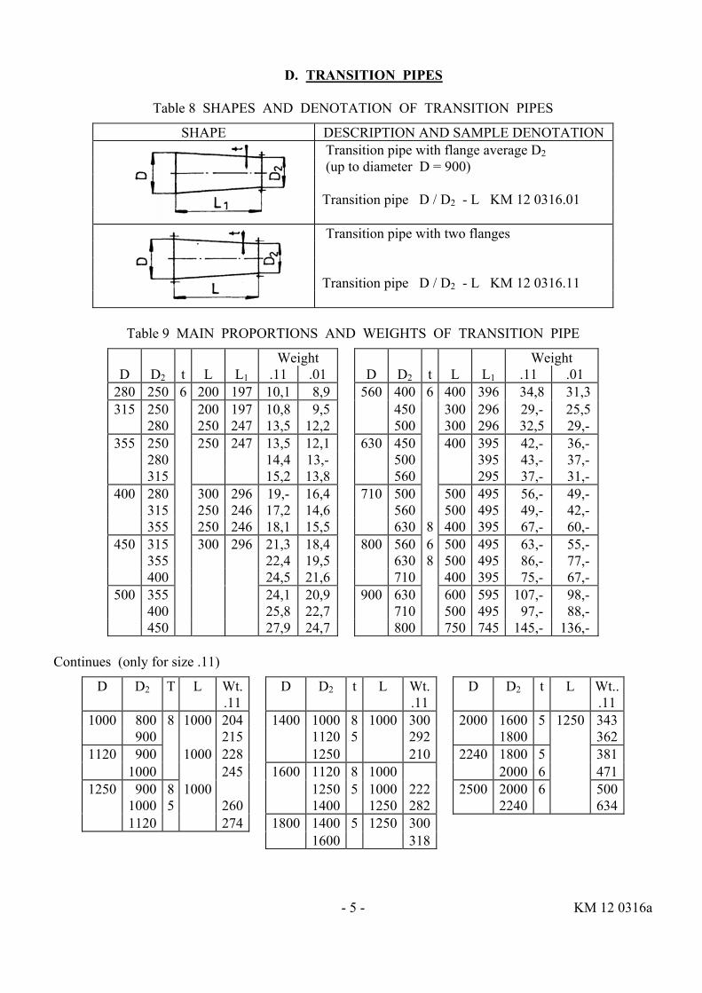
D. TRANSITION PIPES
Table 8 SHAPES AND DENOTATION OF TRANSITION PIPES
SHAPE DESCRIPTION AND SAMPLE DENOTATION Transition pipe with flange average D2 (up to diameter D = 900) Transition pipe D / D2 - L KM 12 0316.01 Transition pipe with two flanges Transition pipe D / D2 - L KM 12 0316.11
Table 9 MAIN PROPORTIONS AND WEIGHTS OF TRANSITION PIPE
Weight Weight D D2 t L L1 .11 .01 D D2 t L L1 .11 .01
280 250 6 200 197 10,1 8,9 560 400 6 400 396 34,8 31,3315 250 200 197 10,8 9,5 450 300 296 29,- 25,5
280 250 247 13,5 12,2 500 300 296 32,5 29,- 355 250 250 247 13,5 12,1 630 450 400 395 42,- 36,-
280 14,4 13,- 500 395 43,- 37,- 315 15,2 13,8 560 295 37,- 31,-
400 280 300 296 19,- 16,4 710 500 500 495 56,- 49,- 315 250 246 17,2 14,6 560 500 495 49,- 42,- 355 250 246 18,1 15,5 630 8 400 395 67,- 60,-
450 315 300 296 21,3 18,4 800 560 6 500 495 63,- 55,- 355 22,4 19,5 630 8 500 495 86,- 77,- 400 24,5 21,6 710 400 395 75,- 67,-
500 355 24,1 20,9 900 630 600 595 107,- 98,- 400 25,8 22,7 710 500 495 97,- 88,- 450 27,9 24,7 800 750 745 145,- 136,-
Continues (only for size .11)
D D2 T L Wt. D D2 t L Wt. D D2 t L Wt.. .11 .11 .11
1000 800 8 1000 204 1400 1000 8 1000 300 2000 1600 5 1250 343 900 215 1120 5 292 1800 362
1120 900 1000 228 1250 210 2240 1800 5 381 1000 245 1600 1120 8 1000 2000 6 471
1250 900 8 1000 1250 5 1000 222 2500 2000 6 500 1000 5 260 1400 1250 282 2240 634 1120 274 1800 1400 5 1250 300 1600 318
- 5 - KM 12 0316a
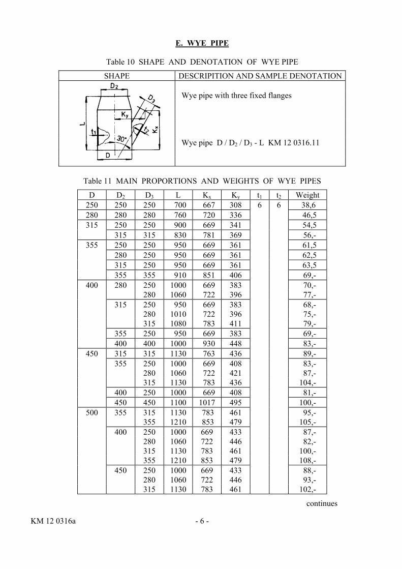
E. WYE PIPE
Table 10 SHAPE AND DENOTATION OF WYE PIPE
SHAPE DESCRIPITION AND SAMPLE DENOTATION Wye pipe with three fixed flanges Wye pipe D / D2 / D3 - L KM 12 0316.11
Table 11 MAIN PROPORTIONS AND WEIGHTS OF WYE PIPES
D D2 D3 L Kx Ky t1 t2 Weight 250 250 250 700 667 308 6 6 38,6 280 280 280 760 720 336 46,5 315 250 250 900 669 341 54,5
315 315 830 781 369 56,- 355 250 250 950 669 361 61,5
280 250 950 669 361 62,5 315 250 950 669 361 63,5 355 355 910 851 406 69,-
400 280 250 1000 669 383 70,- 280 1060 722 396 77,- 315 250 950 669 383 68,- 280 1010 722 396 75,- 315 1080 783 411 79,- 355 250 950 669 383 69,- 400 400 1000 930 448 83,-
450 315 315 1130 763 436 89,- 355 250 1000 669 408 83,- 280 1060 722 421 87,- 315 1130 783 436 104,- 400 250 1000 669 408 81,- 450 450 1100 1017 495 100,-
500 355 315 1130 783 461 95,- 355 1210 853 479 105,- 400 250 1000 669 433 87,- 280 1060 722 446 82,- 315 1130 783 461 100,- 355 1210 853 479 108,- 450 250 1000 669 433 88,- 280 1060 722 446 93,- 315 1130 783 461 102,-
continues
KM 12 0316a - 6 -
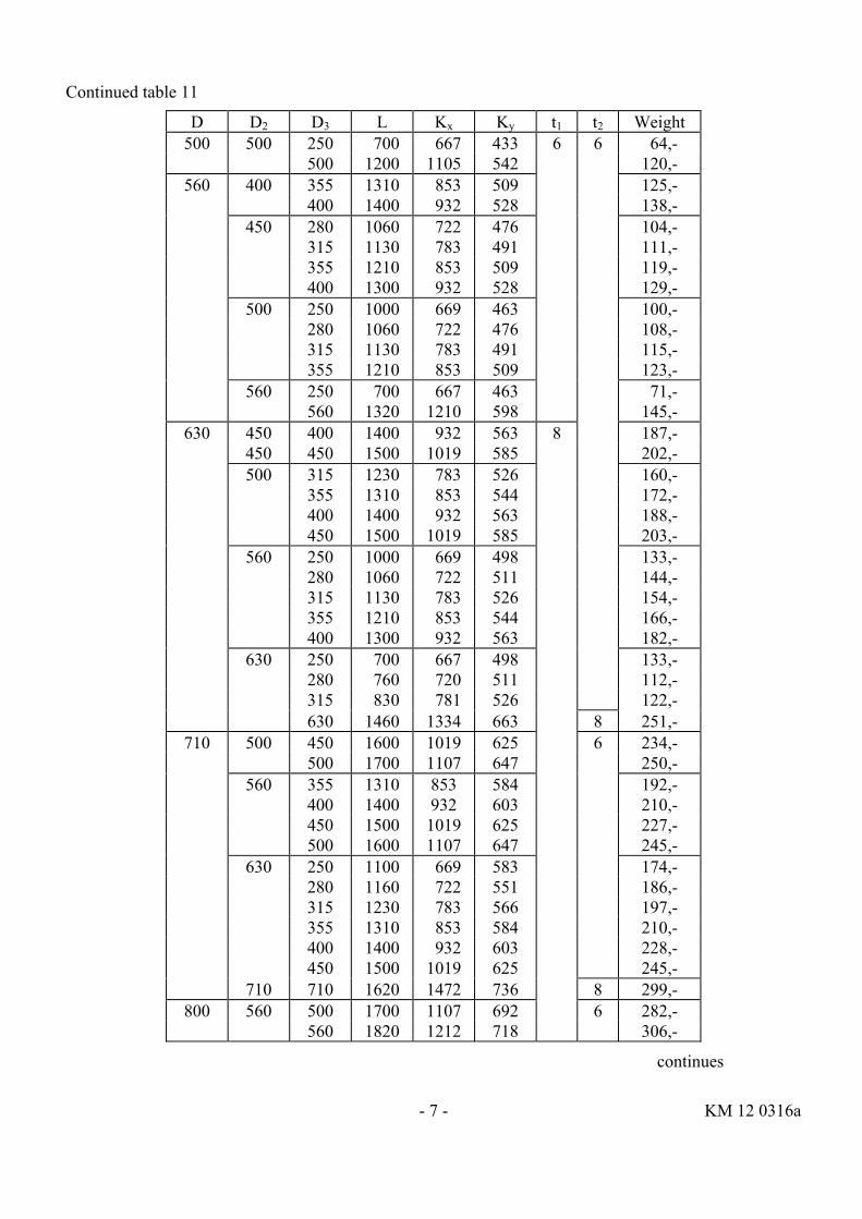
Continued table 11
D D2 D3 L Kx Ky t1 t2 Weight 500 500 250 700 667 433 6 6 64,-
500 1200 1105 542 120,- 560 400 355 1310 853 509 125,-
400 1400 932 528 138,- 450 280 1060 722 476 104,- 315 1130 783 491 111,- 355 1210 853 509 119,- 400 1300 932 528 129,- 500 250 1000 669 463 100,- 280 1060 722 476 108,- 315 1130 783 491 115,- 355 1210 853 509 123,- 560 250 700 667 463 71,- 560 1320 1210 598 145,-
630 450 400 1400 932 563 8 187,- 450 450 1500 1019 585 202,- 500 315 1230 783 526 160,- 355 1310 853 544 172,- 400 1400 932 563 188,- 450 1500 1019 585 203,- 560 250 1000 669 498 133,- 280 1060 722 511 144,- 315 1130 783 526 154,- 355 1210 853 544 166,- 400 1300 932 563 182,- 630 250 700 667 498 133,- 280 760 720 511 112,- 315 830 781 526 122,- 630 1460 1334 663 8 251,-
710 500 450 1600 1019 625 6 234,- 500 1700 1107 647 250,- 560 355 1310 853 584 192,- 400 1400 932 603 210,- 450 1500 1019 625 227,- 500 1600 1107 647 245,- 630 250 1100 669 583 174,- 280 1160 722 551 186,- 315 1230 783 566 197,- 355 1310 853 584 210,- 400 1400 932 603 228,- 450 1500 1019 625 245,- 710 710 1620 1472 736 8 299,-
800 560 500 1700 1107 692 6 282,- 560 1820 1212 718 306,-
continues
- 7 - KM 12 0316a

Continued table 11
D D2 D3 L Kx Ky t1 t2 Weight 800 630 400 1500 932 648 8 6 265,-
450 1600 1019 670 290,- 500 1700 1107 692 304,- 560 1820 1212 718 328,- 710 280 1160 722 596 206,- 315 1230 783 611 218,- 355 1310 853 629 234,- 400 1400 932 648 255,- 450 1500 1019 670 274,-
900 630 630 2060 1334 798 8 400,- 710 500 1700 1107 742 6 340,- 560 1820 1212 768 366,- 630 1960 1334 798 8 408,- 800 315 1580 783 661 6 289,- 355 1670 853 679 304,- 400 1760 932 698 324,- 450 1860 1019 720 343,- 500 1960 1107 742 388,-
ZVVZ a. s. Tel: 382552728 Sažinova 888 Fax: 382521252 399 25 MILEVSKO e-mail: [email protected] KM 12 0316a
ZVVZ a. s. Ecological equipment supplier
INSTRUCTIONS
CIRCULATR PIPING PARTS - THICK WALLED
Base number: KM 12 0316a Attachment 1 Pages total: 4
MARCH 1998
Attachment 1 to KM 12 0316a
1 INTRODUCTION 1.1 The instructions for the thick walled circular piping (further as parts) are designed to be used by any party installing them into their operations. The instructions contain safety precautions, supply, shipping, hand over, storage, installation, maintenance, disposal and guarantees.
1.2 Maintenance of the parts may be done only by authorised personnel trained for such work and in accordance to these instructions.
PIPE
1.3 The products specifications are detailed in the affixed label.
2 SAFETY 2.1 Safety is a condition of the quality of installation into the pipeline network.
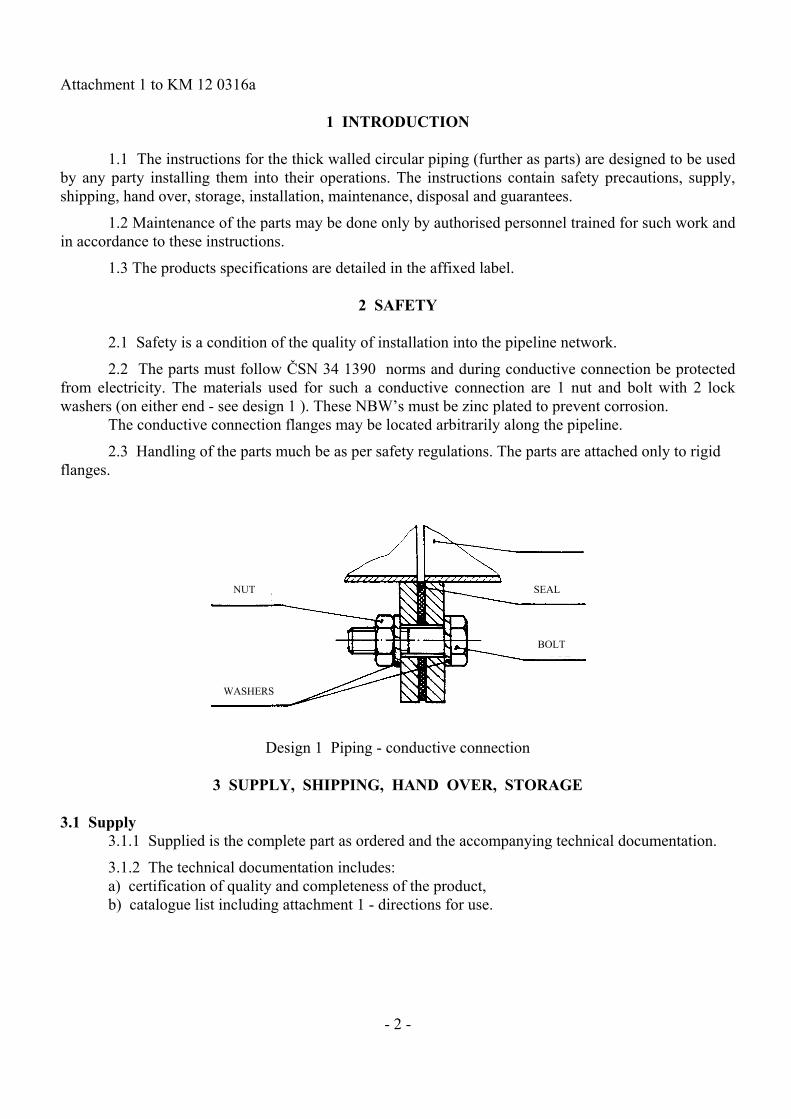
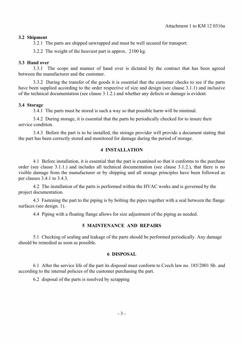
2.2 The parts must follow ČSN 34 1390 norms and during conductive connection be protected from electricity. The materials used for such a conductive connection are 1 nut and bolt with 2 lock washers (on either end - see design 1 ). These NBW’s must be zinc plated to prevent corrosion. The conductive connection flanges may be located arbitrarily along the pipeline.
2.3 Handling of the parts much be as per safety regulations. The parts are attached only to rigid flanges.
NUT SEAL
BOLT
WASHERS
Design 1 Piping - conductive connection
3 SUPPLY, SHIPPING, HAND OVER, STORAGE
3.1 Supply 3.1.1 Supplied is the complete part as ordered and the accompanying technical documentation.
3.1.2 The technical documentation includes: a) certification of quality and completeness of the product, b) catalogue list including attachment 1 - directions for use.
- 2 -
Attachment 1 to KM 12 0316a 3.2 Shipment 3.2.1 The parts are shipped unwrapped and must be well secured for transport.
3.2.2 The weight of the heaviest part is approx. 2100 kg. 3.3 Hand over 3.3.1 The scope and manner of hand over is dictated by the contract that has been agreed between the manufacturer and the customer.
3.3.2 During the transfer of the goods it is essential that the customer checks to see if the parts have been supplied according to the order respective of size and design (see clause 3.1.1) and inclusive of the technical documentation (see clause 3.1.2.) and whether any defects or damage is evident. 3.4 Storage 3.4.1 The parts must be stored is such a way so that possible harm will be minimal.
3.4.2 During storage, it is essential that the parts be periodically checked for to insure their service condition.
3.4.3 Before the part is to be installed, the storage provider will provide a document stating that the part has been correctly stored and monitored for damage during the period of storage.
4 INSTALLATION 4.1 Before installation, it is essential that the part is examined so that it conforms to the purchase order (see clause 3.1.1.) and includes all technical documentation (see clause 3.1.2.), that there is no visible damage from the manufacturer or by shipping and all storage principles have been followed as per clauses 3.4.1 to 3.4.3.
4.2 The installation of the parts is performed within the HVAC works and is governed by the project documentation.
4.3 Fastening the part to the piping is by bolting the pipes together with a seal between the flange surfaces (see design. 1).
4.4 Piping with a floating flange allows for size adjustment of the piping as needed.
5 MAINTENANCE AND REPAIRS 5.1 Checking of sealing and leakage of the parts should be performed periodically. Any damage should be remedied as soon as possible.
6 DISPOSAL 6.1 After the service life of the part its disposal must conform to Czech law no. 185/2001 Sb. and according to the internal policies of the customer purchasing the part.
6.2 disposal of the parts is resolved by scrapping
- 3 -

Attachment 1 to KM 12 0316a
7 GUARANTEES 7.1 any interference into the construction of the part or use other than what it has been designed for is contrary to these instructions and thus negates any warrantee of any kind.
APPENDIX Related norms and regulations
ČSN 34 1390 Electro technical regulations. Regulations for protection against lightning + Za,Zb,Zc,Z4 PM 12 0505-1 Connection proportions for HVAC attachments. Part 1: Circular flanges Public notice no. 48/1982 Sb., which outlines the general principles of safety in the workplace including later regulations and technical equipment Public notice no. 324/1990 Sb., safety in the workplace and technical equipment used in the process of construction work Processed by: ZVVZ a. s. - DV - TK - TÚ - NOR ZVVZ a. s. - Stoinova 888 - 399 25 Milevsko
- 4 -