Embed Size (px)
Citation preview
Kongsberg Mesotech Ltd.
Port Coquitlam, BC - Canada
FS 70 Trawl Sonar System
Operator Manual
SIMRAD

974-24007001/4.1 III
974-24007001/4.1
FS70 Trawl Sonar System Operator manual
FS70 Trawl Sonar System
IV 974-24007001/4.1
Document revisions
Version Date Written by Checked by Approved by
4.1 January 04, 2011 LF/BC JH BC
About this document
The information contained in this document is subject to change without prior notice.
Kongsberg Mesotech Ltd. shall not be liable for errors contained herein, or for incidental or
consequential damages in connection with the furnishing, performance, or use of this
document.
© 2010 Kongsberg Mesotech Ltd. All rights reserved. No part of this work covered by the
copyright hereon may be reproduced or otherwise copied without prior permission from
Kongsberg Mesotech Ltd.
974-24007001/4.1 V
Table of contents
1 SYSTEM FAMILIARIZATION ............................................................................ 1
1.1 Overview ............................................................................................................. 1
1.2 Equipment List .................................................................................................... 2
1.3 Typical System Configurations .......................................................................... 2
1.4 Display Monitor .................................................................................................. 3
1.5 Processor Unit ..................................................................................................... 4
1.6 Power /TTM Interface Module ........................................................................... 4
1.7 Deployment Housing Unit .................................................................................. 5
1.8 Jointing Tool ....................................................................................................... 5
1.9 Catch Sensors ...................................................................................................... 6
1.10 PI Sensors Option ............................................................................................ 6
1.11 Depth, Temperature & Sensors NMEA Output .............................................. 6
1.12 Trawl Cable, Winch and Block ....................................................................... 6
2 THEORY OF OPERATION ................................................................................... 8
2.1 Introduction ......................................................................................................... 8
2.2 Basic Principles ................................................................................................... 8
2.3 Determining Target Position ............................................................................... 8
2.4 Forming an Image ............................................................................................... 9
2.5 Key Features Setting ......................................................................................... 10
2.5.1 Automatic Gain Control (AGC) ..................................................................... 10
2.5.2 Reverberation Controlled Gain (RCG) ........................................................... 10
2.5.3 RX Gain Response and Type.......................................................................... 10
2.5.4 Pulse Length Control ...................................................................................... 11
2.5.5 Peak Detection ................................................................................................ 11
3 FS 70 SYSTEM OPERATION ............................................................................. 12
3.1 Introduction ....................................................................................................... 12
3.2 Control Panel .................................................................................................... 13
3.2.1 Operating Control Panel Page ........................................................................ 14
3.2.2 Display Control Panel Page ............................................................................ 15
3.2.3 Setup Control Panel Page ............................................................................... 15
3.2.4 Users Settings Control Panel Page ................................................................. 16
3.2.5 Sensors Control Panel Page ............................................................................ 16
FS70 Trawl Sonar System
VI 974-24007001/4.1
3.2.5.1 PI 40 kHz Channel Sensors Setup ........................................................... 18
3.2.6 PI 40 kHz Sensors Receiver Setup ................................................................. 19
3.2.7 PI 40 kHz Sensors Activation Menu .............................................................. 20
3.2.8 PI 70 kHz Sensors Activation Menu .............................................................. 21
3.2.9 Advanced Panel Page ..................................................................................... 22
3.2.10 Advanced Operation TVG Mode ................................................................... 23
3.2.11 Display Recording Toolbar ............................................................................ 23
3.2.12 Record Selection ............................................................................................. 24
3.3 Display Tools Selection .................................................................................... 25
3.4 Depths and Temperature Graphs ...................................................................... 25
3.5 Language Selection ........................................................................................... 26
3.6 Audio Set-up ..................................................................................................... 26
3.7 Activating the Sonar ......................................................................................... 27
4 FS 70 INSTALLATION INSTRUCTIONS ......................................................... 29
4.1 Installation procedure ....................................................................................... 29
4.2 Surface Unit Installation ................................................................................... 29
4.2.1 Mounting of Units .......................................................................................... 29
4.2.2 Ship Power Requirement ................................................................................ 30
4.2.3 Display Unit .................................................................................................... 31
4.2.4 Power/TTM Unit ............................................................................................ 31
4.2.5 Connecting the Processing Unit ..................................................................... 32
4.2.6 Interconnect Cables Description ..................................................................... 33
4.2.7 Connection the USB Security Key “Dongle” ................................................. 33
4.2.8 Connecting the USB/RS232 to the TTM Unit ............................................... 34
4.2.9 Optional Ethernet Server Device Specification .............................................. 35
4.2.10 Connecting the Optional Ethernet Server Device to the TTM Unit ............... 36
4.2.11 Connecting a GPS ........................................................................................... 37
4.2.12 Connecting a Echo Sounder ........................................................................... 37
4.2.13 Connecting a Heading Sensor......................................................................... 37
4.2.14 Connection to Cable Winch/Slip-Rings ......................................................... 38
4.2.15 Assembling of the Trawl Unit ........................................................................ 38
4.2.16 FS 70 Configuration ....................................................................................... 38
4.3 System Set-up and Testing using the test cable ................................................ 39
974-24007001/4.1 VII
4.3.1 FS Processor & TTM Communication set-Up ............................................... 39
4.3.2 Optional Ethernet Processor System Set-Up .................................................. 39
4.3.3 Security Firewall Protection System Set-Up .................................................. 43
4.3.4 Start Up ........................................................................................................... 44
4.3.5 Power-Up Configuration ................................................................................ 45
4.3.6 Selecting the Trawl Output Voltage ............................................................... 45
4.3.7 FS 70 Start-up Procedure ................................................................................ 46
4.3.8 FS 70 Run-up Procedure ................................................................................ 49
4.3.9 Advanced Menu Display Settings .................................................................. 50
4.3.10 Control Setting ................................................................................................ 50
4.3.11 Head Sensors Setting ...................................................................................... 51
4.3.12 FS 70 Head Setting ......................................................................................... 52
4.3.13 Transmit Setting ............................................................................................. 53
4.3.14 System Info ..................................................................................................... 54
4.3.15 TVG Page Setting ........................................................................................... 55
4.3.16 Sensors Page ................................................................................................... 56
4.3.17 Auxiliary Transducer (Net Sounder) .............................................................. 57
4.3.18 Save User setting ............................................................................................ 58
4.3.19 Add User Setting ............................................................................................ 59
4.3.20 Final System Test ........................................................................................... 60
4.3.21 Completing the Trawl Unit Assembly ............................................................ 60
4.3.22 Mounting the Catch Sensors ........................................................................... 61
4.3.23 Mounting the Geometry Sensors .................................................................... 62
4.3.24 PI Receiver Basic Configuration Settings ...................................................... 63
5 TROUBLESHOOTING AND MAINTENANCE ............................................... 64
5.1 Introduction ....................................................................................................... 64
5.2 System overview ............................................................................................... 64
5.3 Handling & maintenance .................................................................................. 64
5.3.1 Wheelhouse Electronics ................................................................................. 65
5.3.2 Trawl Unit ...................................................................................................... 65
5.3.2.1 Handling Tips .......................................................................................... 65
5.3.2.2 Maintenance Schedule............................................................................. 66
FS70 Trawl Sonar System
VIII 974-24007001/4.1
5.3.2.3 Connector Maintenance........................................................................... 67
5.3.2.4 Excessive Impacts ................................................................................... 67
5.3.2.5 Corrosion ................................................................................................. 68
5.3.2.6 Shaft or Transducer Damage ................................................................... 68
5.3.3 FA 701 Catch and PI Sensors ......................................................................... 68
5.3.4 Winch Slip-Rings and Trawl Cable ................................................................ 69
5.4 On-board System Troubleshooting ................................................................... 70
5.4.1 System Tools .................................................................................................. 70
5.4.2 Test Cable ....................................................................................................... 71
5.4.3 Power Supply Meter Readings ....................................................................... 71
5.4.4 Trawl Cable Gain............................................................................................ 72
5.4.5 Testing the Trawl Cable ................................................................................. 73
5.4.5.1 Trawl Cable Insulation Measurement ..................................................... 73
5.4.5.2 Closed Loop Resistance, Voltage and Current at Trawl Unit ................. 73
5.4.5.3 Test for Water Ingress in the Trawl Cable .............................................. 75
5.4.6 Telemetry Errors ............................................................................................. 76
5.4.7 Diagnostic Recordings .................................................................................... 76
5.4.8 System Info Page ............................................................................................ 77
5.4.9 Bitmap “Snapshots” Sonar Image .................................................................. 77
5.4.10 Manual Recordings ......................................................................................... 78
5.4.11 Automatic Recordings .................................................................................... 79
5.4.12 Diagnostic and Message Files Transfer Procedure ........................................ 79
5.4.13 Diagnosing Problems ...................................................................................... 80
5.4.14 Troubleshooting Problems .............................................................................. 81
5.4.15 Power up Sequence of Events ........................................................................ 81
5.4.16 Host FS70 Software Start-up Sequence of Events ......................................... 82
5.4.17 What happens when you click “RUN” ........................................................... 82
5.5 Catch sensors .................................................................................................... 85
5.6 Winch slip-rings and trawl cable ...................................................................... 85
6 DRAWINGS ........................................................................................................... 86
ANNEX A - FS SONAR TEST REPORT ................................................................... 95
WARRANTY POLICY ................................................................................................. 97

974-24007001/4.1 IX
<This page is left intentionally blank>

FS70 Trawl Sonar System
X 974-24007001/4.1
<This page is left intentionally blank>
System Familiarization
974-24007001/4.1 1
1 SYSTEM FAMILIARIZATION
1.1 Overview
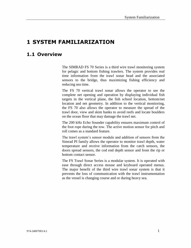
The SIMRAD FS 70 Series is a third wire trawl monitoring system
for pelagic and bottom fishing trawlers. The system provides real
time information from the trawl sonar head and the associated
sensors to the bridge, thus maximizing fishing efficiency and
reducing sea time.
The FS 70 vertical trawl sonar allows the operator to see the
complete net opening and operation by displaying individual fish
targets in the vertical plane, the fish school location, bottom/net
location and net geometry. In addition to the vertical monitoring,
the FS 70 also allows the operator to measure the spread of the
trawl door, view and skim banks to avoid reefs and locate boulders
on the ocean floor that may damage the trawl net.
The 200 kHz Echo Sounder capability ensures maximum control of
the foot rope during the tow. The active motion sensor for pitch and
roll comes as a standard feature.
The trawl system’s sensor module and addition of sensors from the
Simrad PI family allows the operator to monitor trawl depth, water
temperature and receive information from the catch sensors, the
doors spread sensors, the cod end depth sensor and from the rip or
bottom contact sensor.
The FS Trawl Sonar Series is a modular system. It is operated with
ease through direct access mouse and keyboard operated menus.
The major benefit of the third wire trawl sonar system is that it
prevents the loss of communication with the trawl instrumentation
as the vessel is changing course and or during heavy sea.
FS70 Trawl Sonar System
2 974-24007001/4.1
1.2 Equipment List
A typical FS70 Trawl Monitoring System consists of:
FS 70 Deployment Housing
FS 70, Vertical Sonar Head 120kHz, or 330kHz,
200kHz Sounder Transducer
40kHz or 70kHz Catch Sensors
FS PWR/TTM Interface Unit
USB/RS232 or optional Ethernet/RS232 converters
FS 70 PC based Processing Unit.
LCD display monitors.
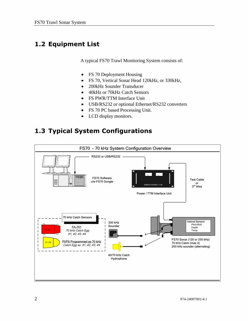
1.3 Typical System Configurations
FS70 - 70 kHz System Configuration Overview
SIMRAD POWER / TTM
RS232 or USB/RS232
200 kHz
Sounder
40/70 kHz Catch
Hydrophone
FS70 Sonar (120 or 330 kHz)
70 kHz Catch (max 4)
200 kHz sounder (alternating)
FA 701 FA-701
70 kHz Catch Egg #1, #2, #3, #4
PI / PS PI/PS Programmed as 70 kHz
Catch Egg as #1, #2, #3, #4
Power / TTM Interface Unit
FS70 Software
c/w FS70 Dongle
Internal Sensors
· Pitch/Roll
· Depth
· Temp
70 kHz Catch Sensors
Test Cable
or
3rd
Wire
System Familiarization
974-24007001/4.1 3
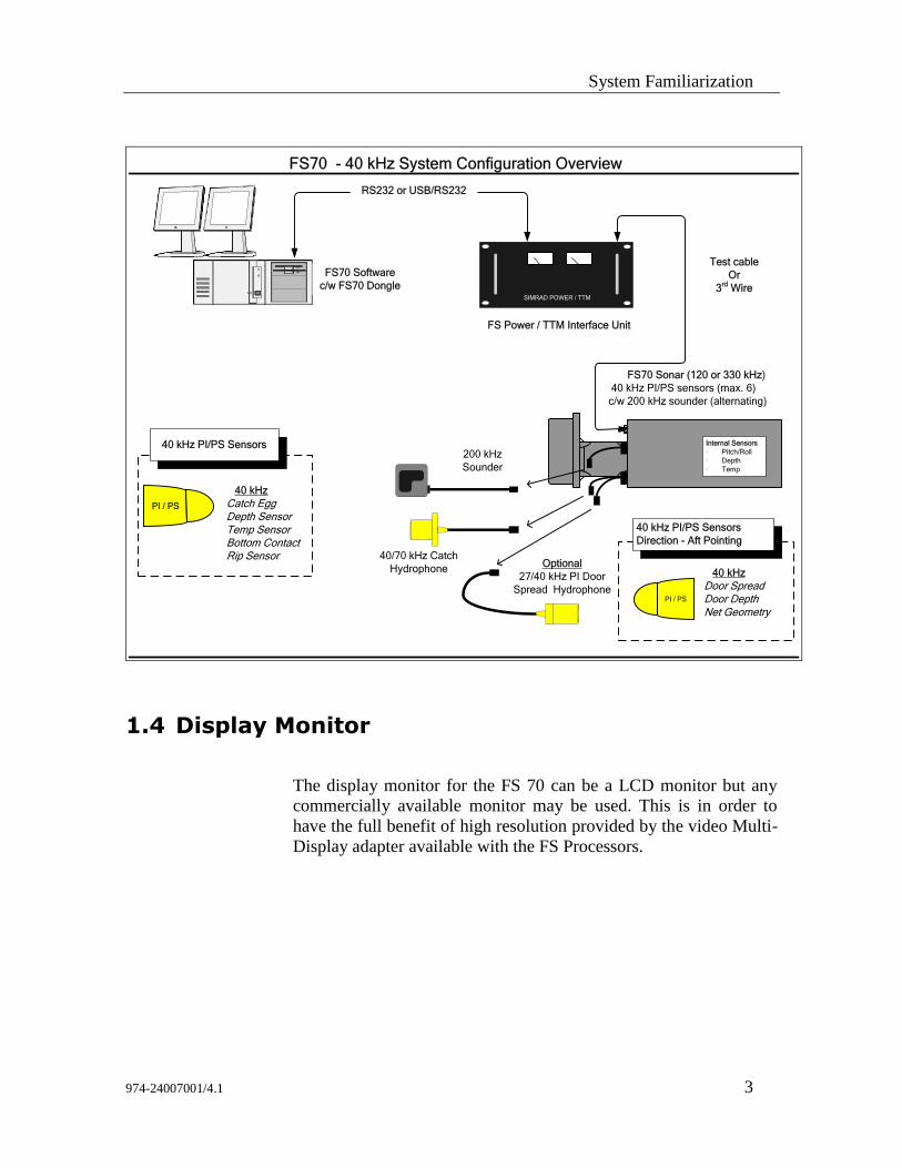
FS70 - 40 kHz System Configuration Overview
SIMRAD POWER / TTM
RS232 or USB/RS232
200 kHz
Sounder
40/70 kHz Catch
Hydrophone
FS70 Sonar (120 or 330 kHz)
40 kHz PI/PS sensors (max. 6)
c/w 200 kHz sounder (alternating)
PI / PS
40 kHz
Catch EggDepth SensorTemp SensorBottom ContactRip Sensor
FS Power / TTM Interface Unit
FS70 Software
c/w FS70 Dongle
Internal Sensors
· Pitch/Roll
· Depth
· Temp
40 kHz PI/PS Sensors
Test cable
Or
3rd
Wire
Optional
27/40 kHz PI Door
Spread Hydrophone
40 kHz PI/PS Sensors
Direction - Aft Pointing
40 kHz
Door SpreadDoor DepthNet Geometry
PI / PS
1.4 Display Monitor
The display monitor for the FS 70 can be a LCD monitor but any
commercially available monitor may be used. This is in order to
have the full benefit of high resolution provided by the video Multi-
Display adapter available with the FS Processors.
FS70 Trawl Sonar System
4 974-24007001/4.1
1.5 Processor Unit
The FS 70 19” Rack mounted Industrial Processing unit is the
control unit for the system. The rear panel of the Processing unit
contains the connectors for AC power, Dual Monitor port, one
Serial port and several USB ports, Keyboard, Mouse, Printer, and
Network port. The Network Ethernet port can be used to connect
the remote workstation or connect with the factory for remote
service support.
The installed FS 70 system software provides a mechanism for the
sonar head detection, setup and operation. It is operated through the
Main Control panel to enable the Sonar selection, tilt, range, gain,
cursor, and by moving the mouse pointer over the toolbar will allow
the operator to perform certain operations with a simple Right or
Left mouse click.
The sector heading and width are also controlled by a single mouse
click used to set the center and the width of the sector scan. In polar
mode the sector width can be extended up to 360°.
NOTE: A security key or (“dongle”) must be attached to a USB
port to enable full operation of the system.
1.6 Power /TTM Interface Module
The FS 19” Rack mounted Power/TTM interface Module unit
provides the supply voltage required by the trawl sonar and the
telemetry translation between the Processing Unit Serial or USB
port and the sonar head. The DC output voltage is combined with
the telemetry signals and supplied to the trawl sonar.
The voltage and current supplied to the sonar head are monitored by
voltage and current meters. A selector switch located below the
voltage meter can be used to select the output voltage of the power
supply required for the appropriate system configuration. Also, a
separate on/off switch is located in the front panel.
NOTE: The main on/off switch input voltage selector and input
fuse are located on the rear panel of the TTM Module.
System Familiarization
974-24007001/4.1 5
A test cable connector and selection switch between the trawl cable
and test cable are accessible on the front panel, providing quick
access for a test cable without disconnecting the 3rd
wire cable from
the rear of the TTM.
1.7 Deployment Housing Unit
The trawl deployment housing unit is made from polyurethane and
designed for the harshest of environments yet it is easy to handle.
The FS 70 trawl unit sits within the deployment housing unit and
contains the vertical sonar head, catch hydrophone receiver, the
optional forward hydrophone, the 200 kHz echo sounder transducer
and depth and temperature sensors. The mounting kit supplied
contains the strain relief cable gland and other hardware used to
attach the trawl cable to the trawl head rope.
The trawl cable is connected to the trawl sonar by a watertight
connector and a locking sleeve.
1.8 Jointing Tool
Jointing tools and materials are required for splicing the trawl cable
and attaching the trawl “2 pin pigtail” connector to the trawl sonar.
We recommend using 3M 72-N1 jointing tool kits that can be
purchase locally and are designed for coaxial cable with a breaking
point of 1500kg. The jointing kit will allow you to make 1 cable
joint.
NOTE: The size of the required joining and crimping sleeve
will be determined by the type of 3rd
wire you are using.
FS70 Trawl Sonar System
6 974-24007001/4.1
1.9 Catch Sensors
The catch sensor “eggs” are wireless sensors mounted on the cod-
end of the trawl net to detect the stretch of the net as it fills up with
the catch. When sufficient stretch of the net occurs, the catch sensor
is triggered and sends an acoustic signal to the trawl sonar through
the catch receiver. The information is then sent to the processor and
displayed on the monitor.
The sensors have a rugged construction in order to withstand the
strain from winches and the power block. The operator can use up
to six sensors (with the 40 kHz system) simultaneously. The catch
sensors are equipped with rechargeable batteries.
1.10 PI Sensors Option
The FS 70 provides full integration with the PI System sensors.
Door Spread, Net Geometry, Bottom Contact, Rip Sensor and Cod
End Depth Sensors available from Simrad AS, Horten Norway.
1.11 Depth, Temperature & Sensors NMEA Output
The FS 70 Processing Unit can be configured to output NMEA data
information. The integrated sensor module will output Depth,
Temperature and PI Sensors data when interfaced to echo sounders
or other onboard equipments. The head rope depth information
appears on the sounder showing the location of the trawl in relation
to the fish or bottom returns.
1.12 Trawl Cable, Winch and Block
The trawl cable and the associated equipment are supplied by the
vessel. The trawl cable is chosen for maximum mechanical strength,
durability and minimum attenuation of the signals. Cables in
common use are coaxial with breaking points of 1500kg and
6000kg.
System Familiarization
974-24007001/4.1 7
Cable winches are delivered in different types and with different
capacities; low-pressure hydraulic, high-pressure hydraulic and
electrically driven. Choice of winch is dependent on prevailing
conditions; type and length of cable and available source of power.
Most types operate automatically - the cable is pulled out, kept tight
during towing, and hauled in together with the trawl. Control of the
winch is done remotely from the bridge.
Any commercially available pulley block may be used to properly
align the cable onto the winch. A snatch block has the advantage
that it may be installed without having to thread the cable through
it. A unit with two movable steering arms (one on each side of the
pulley) is recommended to prevent the cable from coming off the
pulley and causing damage to the cable.
FS70 Trawl Sonar System
8 974-24007001/4.1
2 THEORY OF OPERATION
2.1 Introduction
This section explains the theory of operation of the Vertical and
Sounder Scanning Trawl Monitoring Sonar System.
2.2 Basic Principles
Sound waves travel very efficiently through water.
A sound pulse can be projected through water in a controlled
direction with the sonar transducer.
An object in the path of the projected sound pulse will reflect some
sound pulses back toward the sonar transducer.
The speed of the sound pulse projected through the water can be
predicted for given conditions.
2.3 Determining Target Position
The trawl scanning sonar processor measures the time from the start
of the sound pulse projected through water, to the reception of the
sound pulse reflected back to the sonar transducer. The measured
time is then converted to distance by using the value of sound speed
through water.
Since the sound pulse is projected in a known direction, the bearing
of the reflected object is also known. This makes it possible to
locate the object with respect to the sonar transducer; the
information will be used to plot the position of the reflected target
on a video graphic display monitor.
Theory of Operation
974-24007001/4.1 9
2.4 Forming an Image
The sound pulse projected will be attenuated as it travels through
the water from the transducer to the target and back. Much of this
attenuation is a predictable function of the total time or the distance
the sound pulse travelled through water. Increasing the receiving
gain with time can compensate for this decrease in the signal level.
This is done automatically in the sonar with a Time Varying Gain
(TVG) circuit.
After the TVG correction, the absolute levels of the received signals
will be determined by the acoustic response of the reflecting target.
The sonar processor system repeatedly measures the TVG corrected
target levels by digitizing a sequence of samples after each sound
pulse transmission. Each sample is then plotted on the video display
at the appropriate position according to its range and bearing. The
level of the target strength sample determines the colour used to
plot each sample.
The process can be repeated with the transducer pointed in different
directions, forming an image of a large area of the bottom, (or the
trawl net geometry) and displaying it on the video screen.
In simple words, the TVG function controls the gain of the
receiver so that a school with a given size and density is presented
with approximately the same strength on the display, inside the
regulated TVG range.
FS70 Trawl Sonar System
10 974-24007001/4.1
2.5 Key Features Setting
The following paragraph will explain some of the key features of
the FS 70 System.
2.5.1 Automatic Gain Control (AGC)
The AGC “Automatic Gain Control” algorithm increases the gain
during low acoustic returns and reduces the gain during strong
acoustic returns. The speed with which the gain is adjusted is
determined by the setting of the “RX Gain Response”
2.5.2 Reverberation Controlled Gain (RCG)
The RCG filter senses the noise level (reverberation, propeller
noise, etc.), and adjusts the gain of each of the received beams in
order to eliminate noise on the display. The strength of the filter can
be selected in the menu. With maximum strength selected, the RCG
will effectively reduce the bottom in shallow water, while variation
on the bottom will be displayed.
Note that scattered fish can be perceived as reverberation. The RCG
filter must be used with care if scattered schools are to be detected.
2.5.3 RX Gain Response and Type
The setting of the “RX Gain Response” determines the response of
the filter algorithm as selected by the “RX Gain Type”. For the
AGC, this setting determines the speed by which the gain is
adjusted. For the RCG, this setting determines the influence of the
previous ping average over the current ping. If set to “Slow” the
overall average is given by the sum of 20% current and 80% of
previous average. In “Medium” this ratio is 50% to 50%, and in
“Fast” the ratio is 80% to 20%.
Theory of Operation
974-24007001/4.1 11
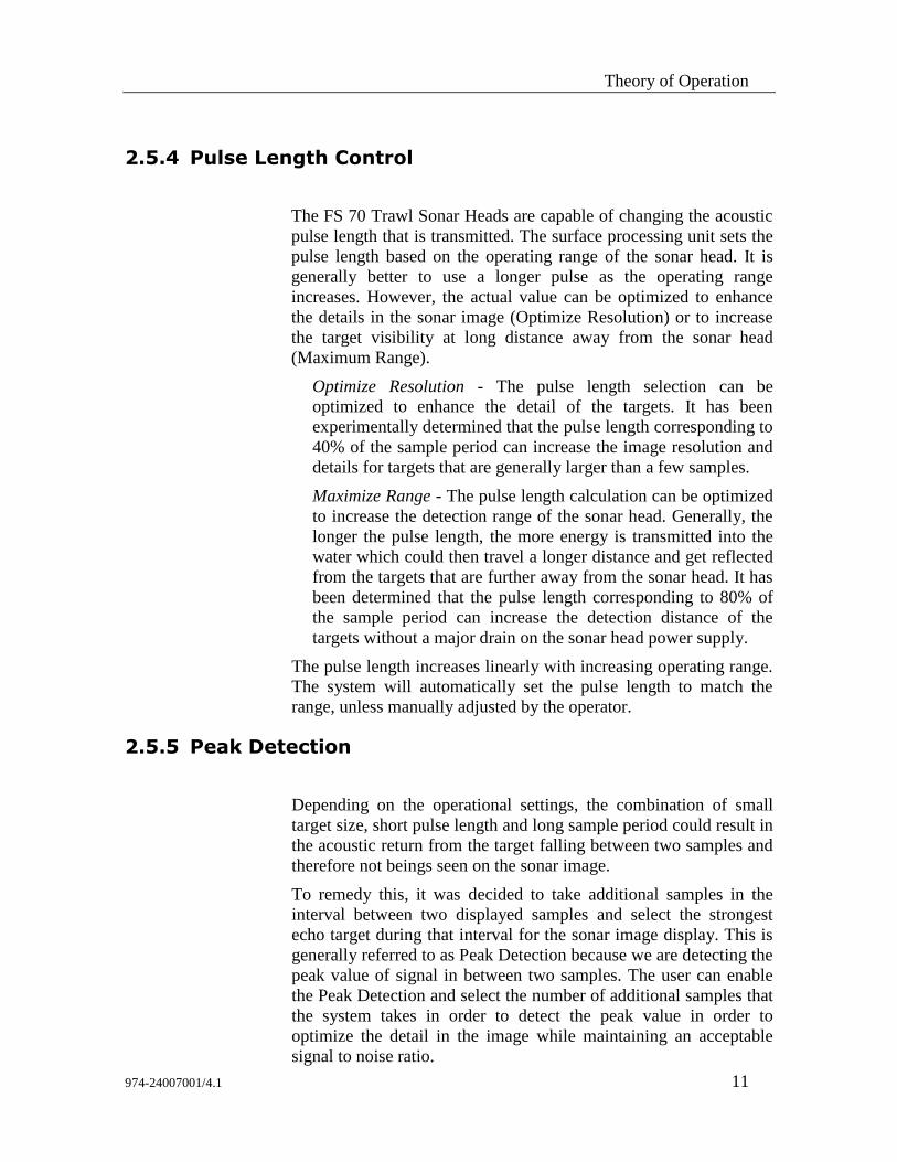
2.5.4 Pulse Length Control
The FS 70 Trawl Sonar Heads are capable of changing the acoustic
pulse length that is transmitted. The surface processing unit sets the
pulse length based on the operating range of the sonar head. It is
generally better to use a longer pulse as the operating range
increases. However, the actual value can be optimized to enhance
the details in the sonar image (Optimize Resolution) or to increase
the target visibility at long distance away from the sonar head
(Maximum Range).
Optimize Resolution - The pulse length selection can be
optimized to enhance the detail of the targets. It has been
experimentally determined that the pulse length corresponding to
40% of the sample period can increase the image resolution and
details for targets that are generally larger than a few samples.
Maximize Range - The pulse length calculation can be optimized
to increase the detection range of the sonar head. Generally, the
longer the pulse length, the more energy is transmitted into the
water which could then travel a longer distance and get reflected
from the targets that are further away from the sonar head. It has
been determined that the pulse length corresponding to 80% of
the sample period can increase the detection distance of the
targets without a major drain on the sonar head power supply.
The pulse length increases linearly with increasing operating range.
The system will automatically set the pulse length to match the
range, unless manually adjusted by the operator.
2.5.5 Peak Detection
Depending on the operational settings, the combination of small
target size, short pulse length and long sample period could result in
the acoustic return from the target falling between two samples and
therefore not beings seen on the sonar image.
To remedy this, it was decided to take additional samples in the
interval between two displayed samples and select the strongest
echo target during that interval for the sonar image display. This is
generally referred to as Peak Detection because we are detecting the
peak value of signal in between two samples. The user can enable
the Peak Detection and select the number of additional samples that
the system takes in order to detect the peak value in order to
optimize the detail in the image while maintaining an acceptable
signal to noise ratio.
FS70 Trawl Sonar System
12 974-24007001/4.1
3 FS 70 SYSTEM OPERATION
3.1 Introduction
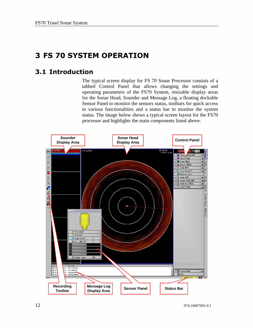
The typical screen display for FS 70 Sonar Processor consists of a
tabbed Control Panel that allows changing the settings and
operating parameters of the FS70 System, resizable display areas
for the Sonar Head, Sounder and Message Log, a floating dockable
Sensor Panel to monitor the sensors status, toolbars for quick access
to various functionalities and a status bar to monitor the system
status. The image below shows a typical screen layout for the FS70
processor and highlights the main components listed above:
Sonar Head
Display Area
Sounder
Display AreaControl Panel
Message Log
Display AreaSensor Panel
Recording
ToolbarStatus Bar
FS 70 System Operation
974-24007001/4.1 13
This chapter describes the navigation through the menu system and
explains the adjustments to the menu settings that may be made to
control the sonar operation
3.2 Control Panel
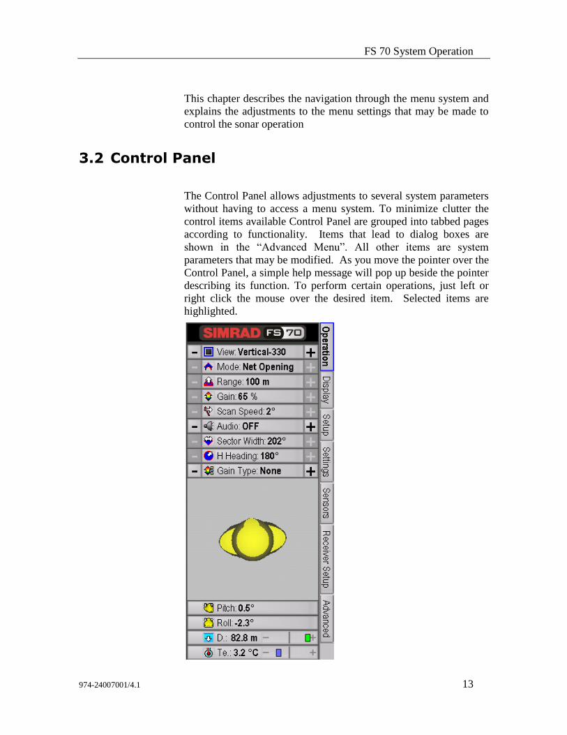
The Control Panel allows adjustments to several system parameters
without having to access a menu system. To minimize clutter the
control items available Control Panel are grouped into tabbed pages
according to functionality. Items that lead to dialog boxes are
shown in the “Advanced Menu”. All other items are system
parameters that may be modified. As you move the pointer over the
Control Panel, a simple help message will pop up beside the pointer
describing its function. To perform certain operations, just left or
right click the mouse over the desired item. Selected items are
highlighted.
FS70 Trawl Sonar System
14 974-24007001/4.1
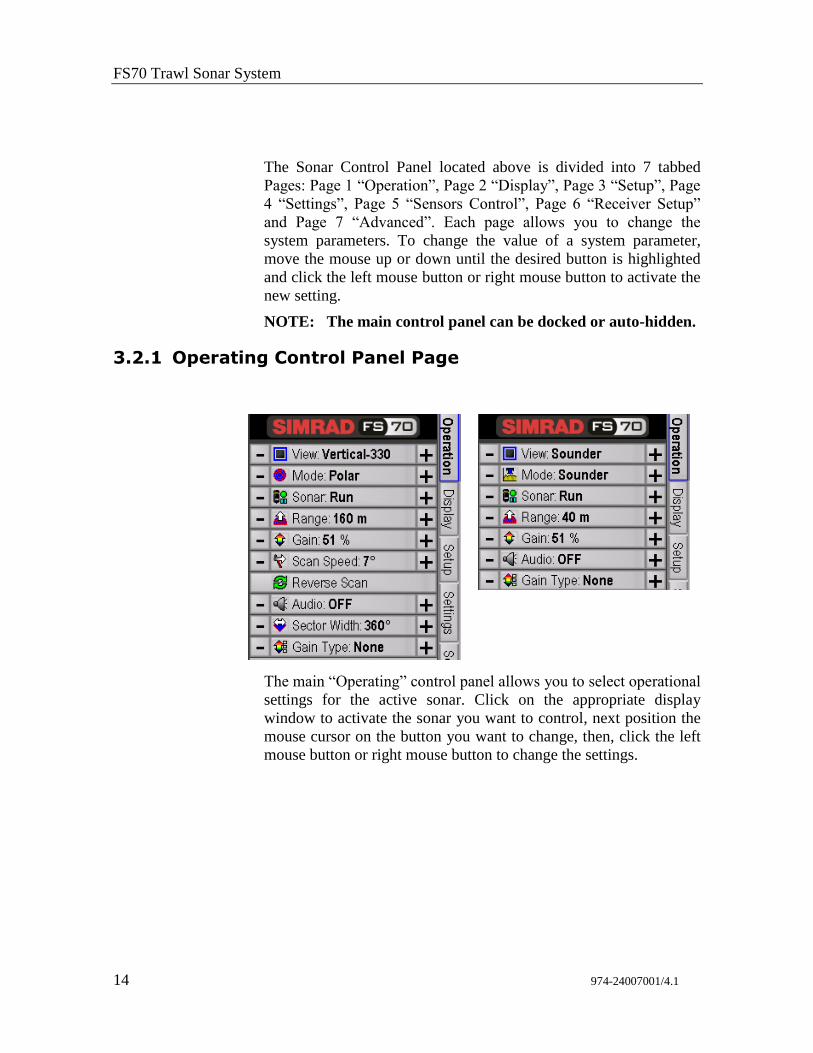
The Sonar Control Panel located above is divided into 7 tabbed
Pages: Page 1 “Operation”, Page 2 “Display”, Page 3 “Setup”, Page
4 “Settings”, Page 5 “Sensors Control”, Page 6 “Receiver Setup”
and Page 7 “Advanced”. Each page allows you to change the
system parameters. To change the value of a system parameter,
move the mouse up or down until the desired button is highlighted
and click the left mouse button or right mouse button to activate the
new setting.
NOTE: The main control panel can be docked or auto-hidden.
3.2.1 Operating Control Panel Page
The main “Operating” control panel allows you to select operational
settings for the active sonar. Click on the appropriate display
window to activate the sonar you want to control, next position the
mouse cursor on the button you want to change, then, click the left
mouse button or right mouse button to change the settings.
FS 70 System Operation
974-24007001/4.1 15
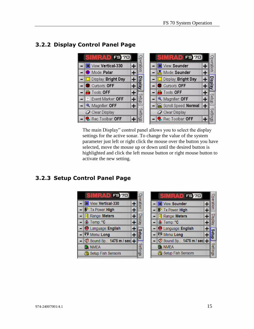
3.2.2 Display Control Panel Page
The main Display” control panel allows you to select the display
settings for the active sonar. To change the value of the system
parameter just left or right click the mouse over the button you have
selected, move the mouse up or down until the desired button is
highlighted and click the left mouse button or right mouse button to
activate the new setting.
3.2.3 Setup Control Panel Page
FS70 Trawl Sonar System
16 974-24007001/4.1
The main “Setup” control panel allows you to set up system
parameters for the active sonar. To change the value of the system
parameter just left or right click the mouse over the button you have
selected, move the mouse up or down until the desired button is
highlighted and click the left mouse button or right mouse button to
activate the new setting.
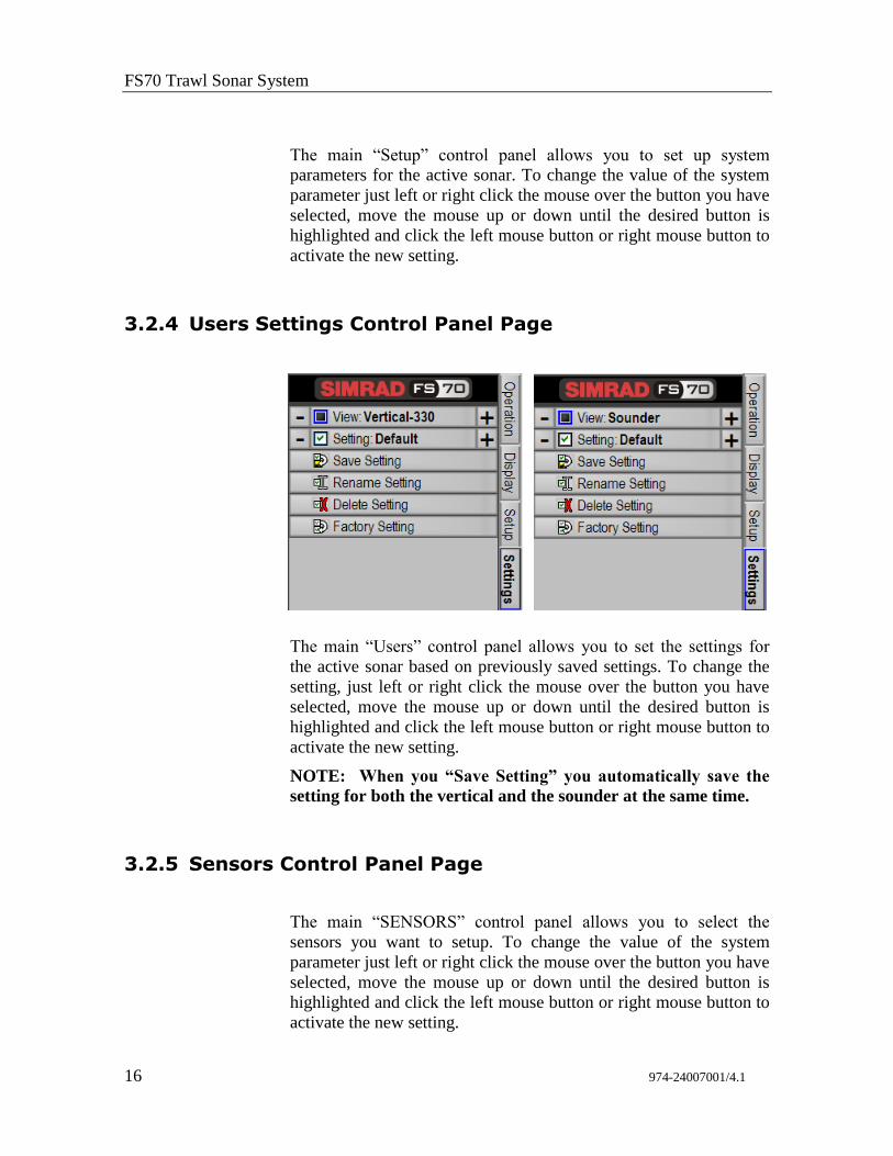
3.2.4 Users Settings Control Panel Page
The main “Users” control panel allows you to set the settings for
the active sonar based on previously saved settings. To change the
setting, just left or right click the mouse over the button you have
selected, move the mouse up or down until the desired button is
highlighted and click the left mouse button or right mouse button to
activate the new setting.
NOTE: When you “Save Setting” you automatically save the
setting for both the vertical and the sounder at the same time.
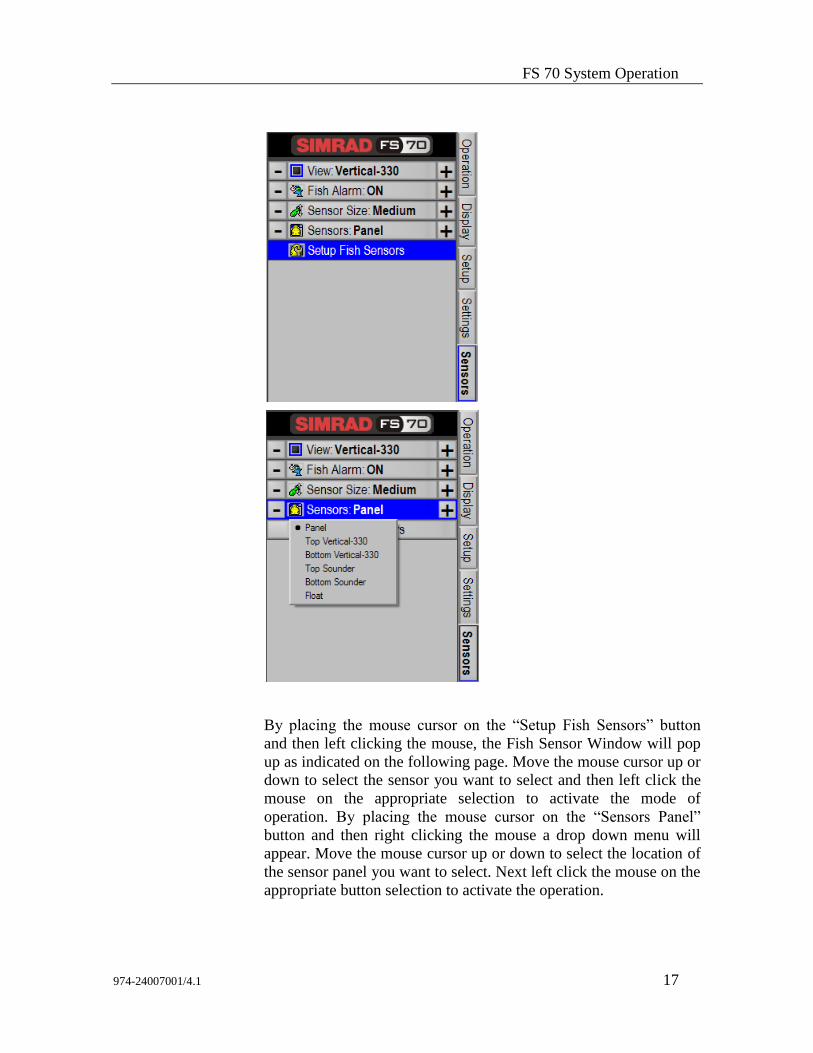
3.2.5 Sensors Control Panel Page
The main “SENSORS” control panel allows you to select the
sensors you want to setup. To change the value of the system
parameter just left or right click the mouse over the button you have
selected, move the mouse up or down until the desired button is
highlighted and click the left mouse button or right mouse button to
activate the new setting.
FS 70 System Operation
974-24007001/4.1 17
By placing the mouse cursor on the “Setup Fish Sensors” button
and then left clicking the mouse, the Fish Sensor Window will pop
up as indicated on the following page. Move the mouse cursor up or
down to select the sensor you want to select and then left click the
mouse on the appropriate selection to activate the mode of
operation. By placing the mouse cursor on the “Sensors Panel”
button and then right clicking the mouse a drop down menu will
appear. Move the mouse cursor up or down to select the location of
the sensor panel you want to select. Next left click the mouse on the
appropriate button selection to activate the operation.
FS70 Trawl Sonar System
18 974-24007001/4.1
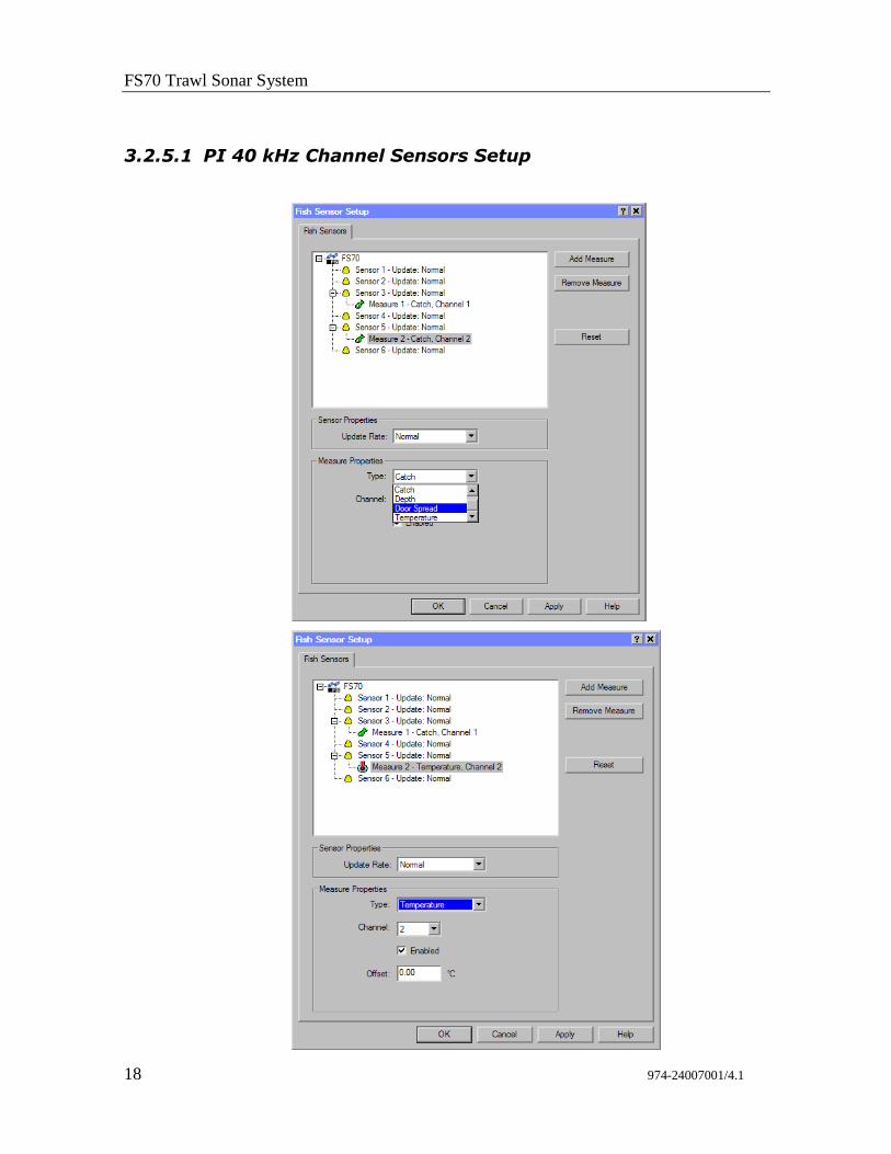
3.2.5.1 PI 40 kHz Channel Sensors Setup
FS 70 System Operation
974-24007001/4.1 19
The next step after the above operation, for example, will be to add
a catch sensor.
Click on “sensor 5”; next select Door Spread or catch #2; next you
would select the channel of operation, in this case you would have
selected #2.
If you are adding for example a temperature sensor you can setup
an offset. See the windows above for the example.
Note: For additional information on the Simrad PI Setup, please
refer to your PI Instruction Manual.
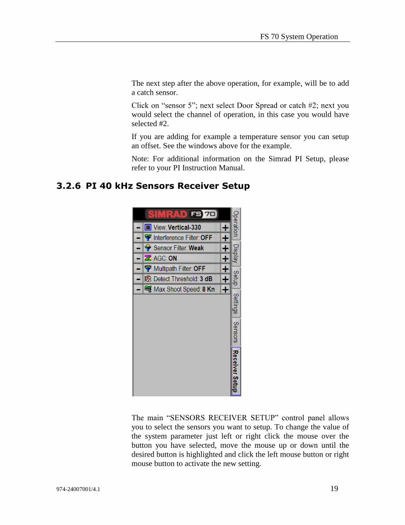
3.2.6 PI 40 kHz Sensors Receiver Setup
The main “SENSORS RECEIVER SETUP” control panel allows
you to select the sensors you want to setup. To change the value of
the system parameter just left or right click the mouse over the
button you have selected, move the mouse up or down until the
desired button is highlighted and click the left mouse button or right
mouse button to activate the new setting.
FS70 Trawl Sonar System
20 974-24007001/4.1
NOTE: For additional information on the Simrad PI Sensors
Setup, please refer to your PI Instruction Manual.
NOTE: The PI sensor setup menus are not available if you are
using a 70 kHz Catch Sensors system.
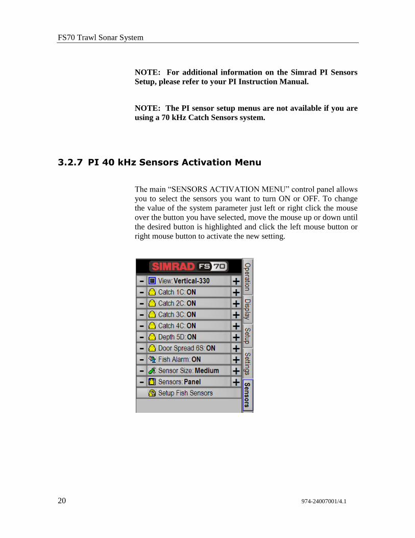
3.2.7 PI 40 kHz Sensors Activation Menu
The main “SENSORS ACTIVATION MENU” control panel allows
you to select the sensors you want to turn ON or OFF. To change
the value of the system parameter just left or right click the mouse
over the button you have selected, move the mouse up or down until
the desired button is highlighted and click the left mouse button or
right mouse button to activate the new setting.
FS 70 System Operation
974-24007001/4.1 21
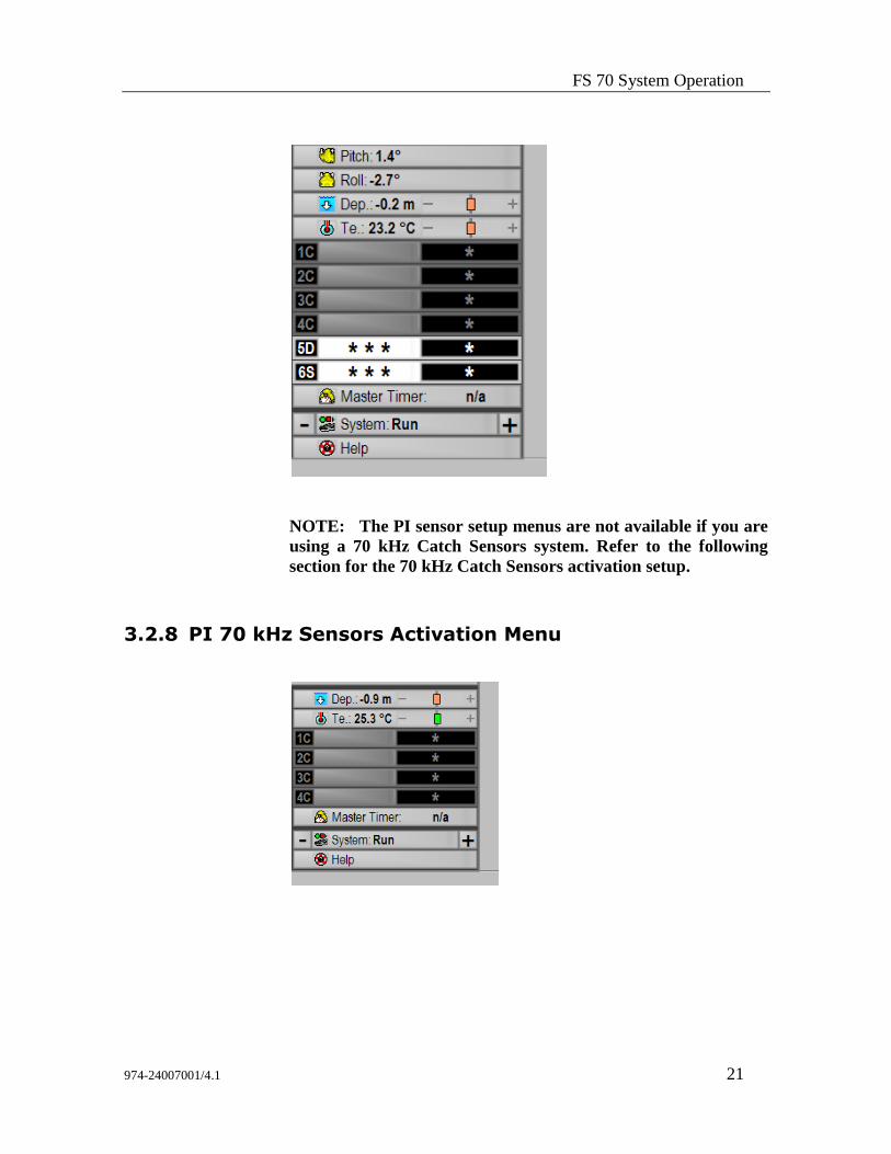
NOTE: The PI sensor setup menus are not available if you are
using a 70 kHz Catch Sensors system. Refer to the following
section for the 70 kHz Catch Sensors activation setup.
3.2.8 PI 70 kHz Sensors Activation Menu
FS70 Trawl Sonar System
22 974-24007001/4.1
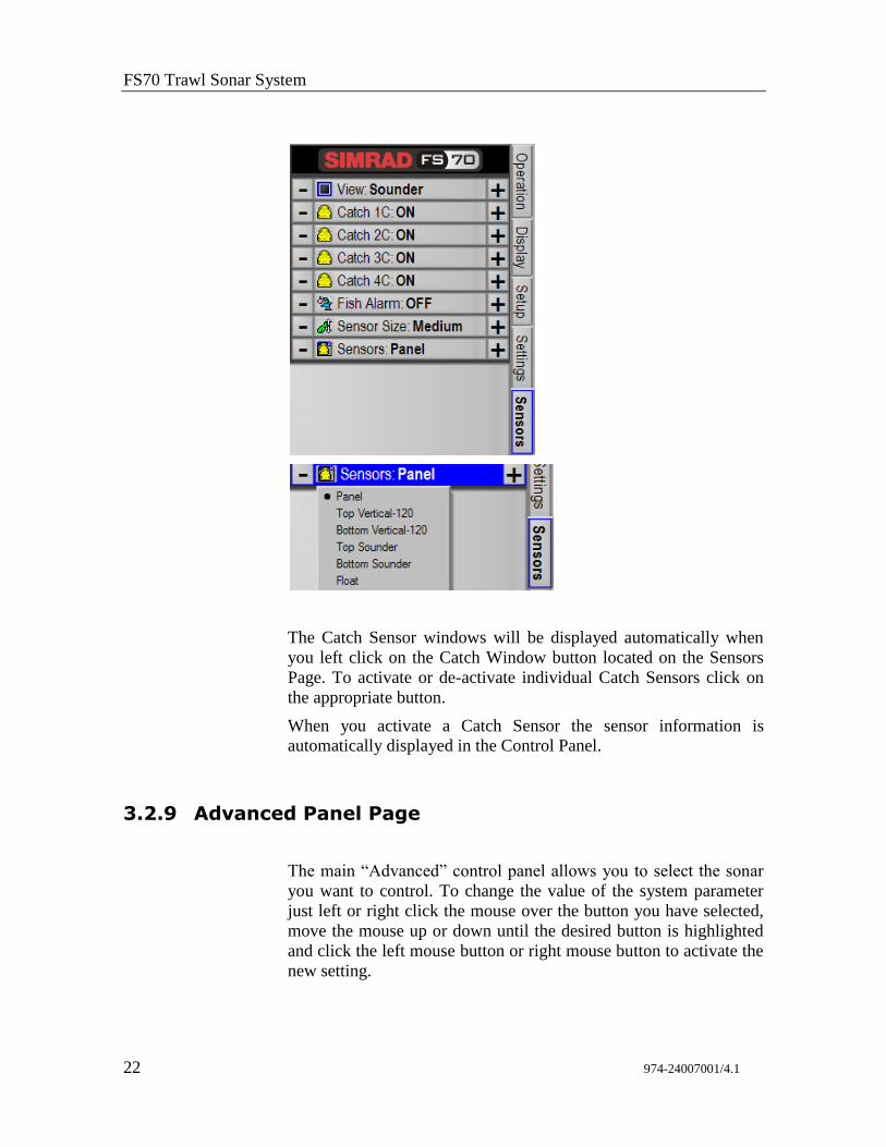
The Catch Sensor windows will be displayed automatically when
you left click on the Catch Window button located on the Sensors
Page. To activate or de-activate individual Catch Sensors click on
the appropriate button.
When you activate a Catch Sensor the sensor information is
automatically displayed in the Control Panel.
3.2.9 Advanced Panel Page
The main “Advanced” control panel allows you to select the sonar
you want to control. To change the value of the system parameter
just left or right click the mouse over the button you have selected,
move the mouse up or down until the desired button is highlighted
and click the left mouse button or right mouse button to activate the
new setting.
FS 70 System Operation
974-24007001/4.1 23
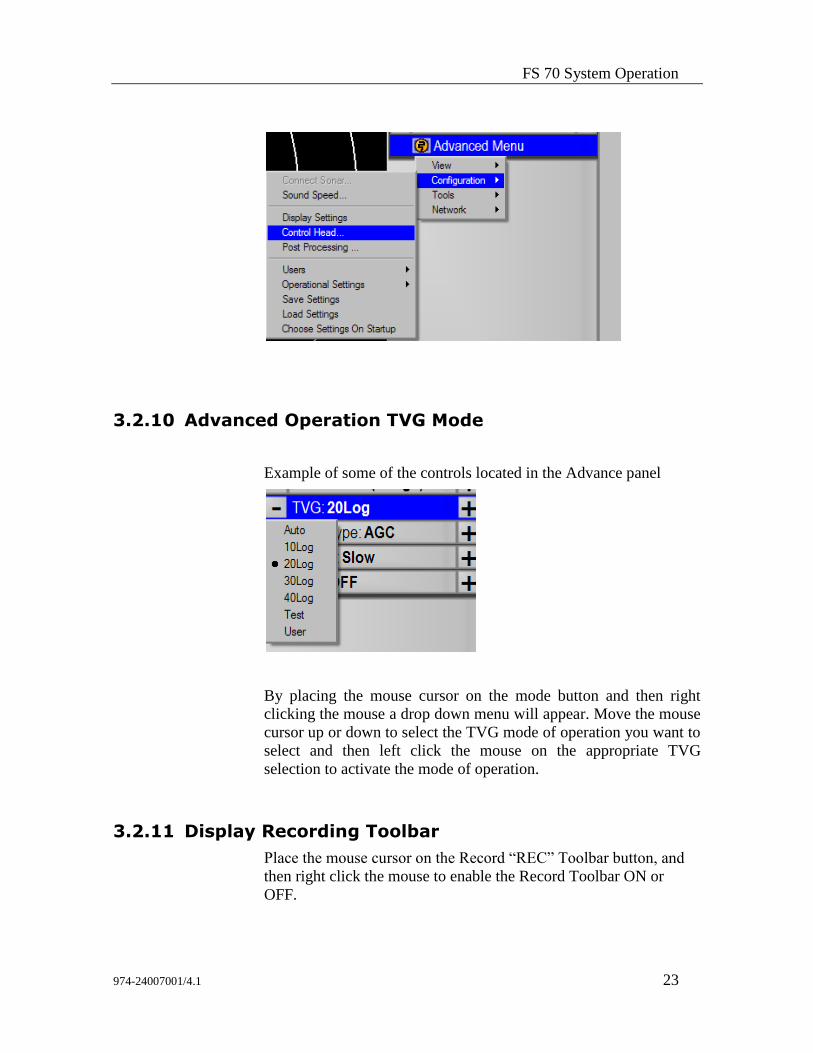
3.2.10 Advanced Operation TVG Mode
Example of some of the controls located in the Advance panel
By placing the mouse cursor on the mode button and then right
clicking the mouse a drop down menu will appear. Move the mouse
cursor up or down to select the TVG mode of operation you want to
select and then left click the mouse on the appropriate TVG
selection to activate the mode of operation.
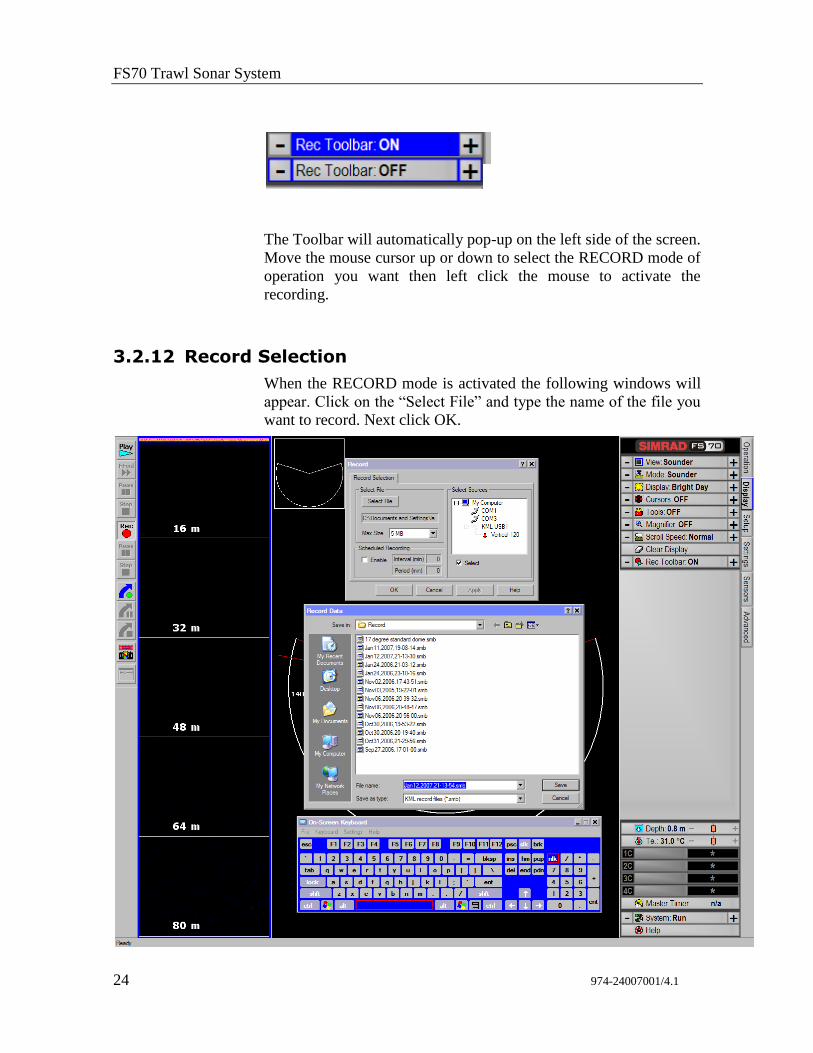
3.2.11 Display Recording Toolbar
Place the mouse cursor on the Record “REC” Toolbar button, and
then right click the mouse to enable the Record Toolbar ON or
OFF.
FS70 Trawl Sonar System
24 974-24007001/4.1
The Toolbar will automatically pop-up on the left side of the screen.
Move the mouse cursor up or down to select the RECORD mode of
operation you want then left click the mouse to activate the
recording.
3.2.12 Record Selection
When the RECORD mode is activated the following windows will
appear. Click on the “Select File” and type the name of the file you
want to record. Next click OK.
FS 70 System Operation
974-24007001/4.1 25
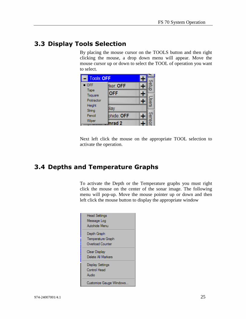
3.3 Display Tools Selection
By placing the mouse cursor on the TOOLS button and then right
clicking the mouse, a drop down menu will appear. Move the
mouse cursor up or down to select the TOOL of operation you want
to select.
Next left click the mouse on the appropriate TOOL selection to
activate the operation.
3.4 Depths and Temperature Graphs
To activate the Depth or the Temperature graphs you must right
click the mouse on the center of the sonar image. The following
menu will pop-up. Move the mouse pointer up or down and then
left click the mouse button to display the appropriate window
FS70 Trawl Sonar System
26 974-24007001/4.1
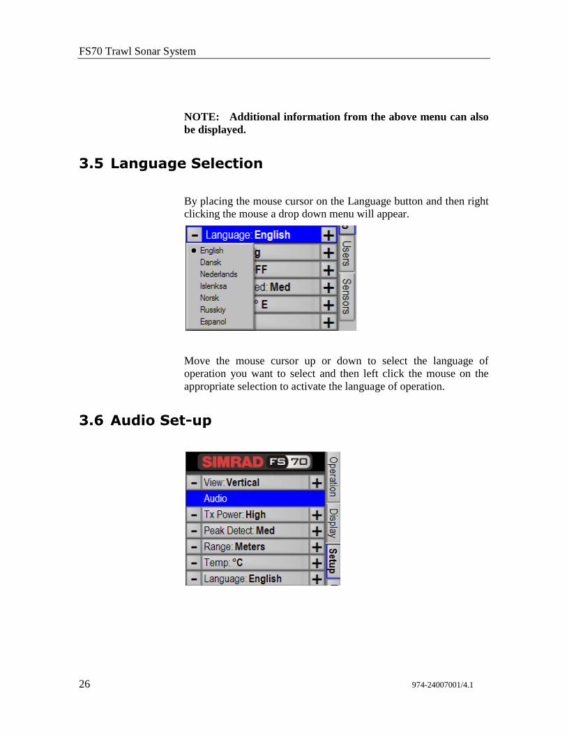
NOTE: Additional information from the above menu can also
be displayed.
3.5 Language Selection
By placing the mouse cursor on the Language button and then right
clicking the mouse a drop down menu will appear.
Move the mouse cursor up or down to select the language of
operation you want to select and then left click the mouse on the
appropriate selection to activate the language of operation.
3.6 Audio Set-up
FS 70 System Operation
974-24007001/4.1 27
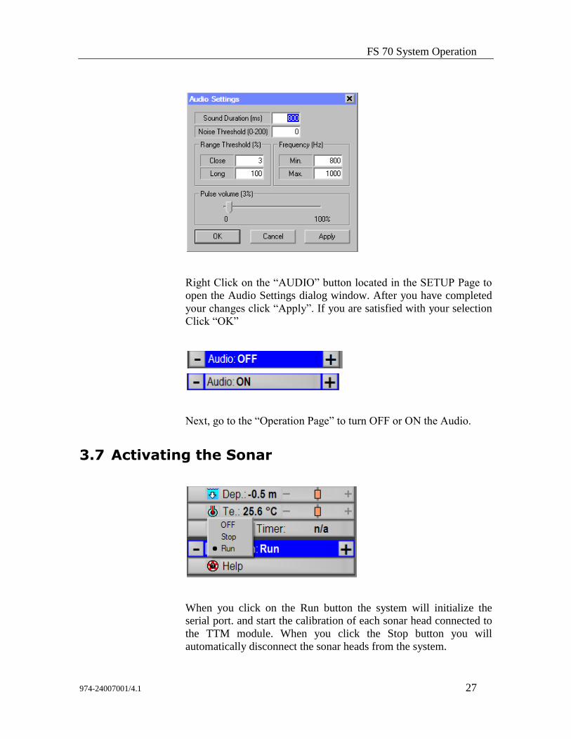
Right Click on the “AUDIO” button located in the SETUP Page to
open the Audio Settings dialog window. After you have completed
your changes click “Apply”. If you are satisfied with your selection
Click “OK”
Next, go to the “Operation Page” to turn OFF or ON the Audio.
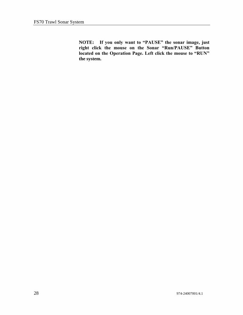
3.7 Activating the Sonar
When you click on the Run button the system will initialize the
serial port. and start the calibration of each sonar head connected to
the TTM module. When you click the Stop button you will
automatically disconnect the sonar heads from the system.
FS70 Trawl Sonar System
28 974-24007001/4.1
NOTE: If you only want to “PAUSE” the sonar image, just
right click the mouse on the Sonar “Run/PAUSE” Button
located on the Operation Page. Left click the mouse to “RUN”
the system.
FS 70 Installation Instructions
974-24007001/4.1 29
4 FS 70 INSTALLATION INSTRUCTIONS
4.1 Installation procedure
The installation of the FS 70 Trawl Monitoring System involves the
following steps:
• Deciding on the locations in the wheel house for the surface units.
• Mounting the surface units and making the connections between the
FS 70 Processor, the display unit, the FS Power Supply/TTM
interface unit, and other optional equipment being installed.
• Assembling the trawl unit.
• Running up the system on the test cable to verify proper installation,
configuring the control unit, and performing initial system tests.
• Installing the cable winch, snatch block and trawl cable, and
connecting the winch slip-rings to the control unit.
• Mounting the trawl unit to the head rope and completing the final
system test.
• Mounting the catch sensors to the cod-end of the trawl and other PI
sensors.
4.2 Surface Unit Installation
4.2.1 Mounting of Units
If you have selected the FS Integrated Rack Mounted System, you
can install the cabinet up to 30 meters from the monitors. With a
KVM extender option you can install the cabinet up to 150 meters
away from the monitors. If not, you will have to follow the
procedure indicated below.
The display unit should be located in the wheel house in a place that
provides a good view of the screen and avoids direct sunlight if
possible. Depending on the monitor that was selected the unit may
be mounted on top or recessed into the bridge console. Simrad
supplied display units include the necessary mounting brackets.
FS70 Trawl Sonar System
30 974-24007001/4.1
If you have not selected the Rack Mounted System, the FS 70
Processing unit should be mounted in close vicinity to the operator's
position in the wheel house and near the display unit. The unit may
be mounted on top of the bridge console or recessed into a cabinet.
Note: You must have access to the ON/OFF switch and provide
proper ventilation to avoid overheating.
The Power Supply/TTM Interface Unit supplied with the system may
be mounted on top of the bridge console or recessed and flush
mounted into the bridge console. Sufficient space should be left
around the control unit for proper ventilation.
Optional equipment for interface to the control unit may be mounted
in any convenient location provided the user supplied interconnects
cables is of sufficient length and the required power is available.
NOTE: The Processing Unit and the Power/TTM must be
connected to a dedicated UPS.
4.2.2 Ship Power Requirement
The display unit, generally, will require 120 VAC or 230 VAC.
Depending on the capabilities of the unit chosen, it may
automatically detect the supply voltage or the unit may have to be
ordered for the correct voltage.
The FS 70 Processor will operate from either 120 VAC or 230 VAC.
IF input voltage must be selected then a voltage input selector switch
is located at the rear of the unit. Some of the processors are equipped
with auto detection voltage input.
The FS Power Supply/TTM module can be operated with either 120
VAC or 230 VAC. Selection of the supply voltage is done by moving
the voltage selector card located in the power entry module at the rear
panel. Details on selecting the proper voltage are indicated on the
voltage card. You must position the “indicator pin” location to the
desired voltage.
To change the input line voltage, use a small blade screwdriver and
pop the cover. Pull the voltage selector card straight out from the
housing, and place the indicator pin to the selected voltage. Reinsert
the card, reinstall the cover and verify that the indicator shows the
desired voltage. You must insure that the proper fuse rating is
installed, 2 A for 230 VAC and 4 A for 110 VAC. Spare fuses are
supplied with the TTM module.
NOTE: Failure to select the proper input voltage will damage
the internal power supply.
FS 70 Installation Instructions
974-24007001/4.1 31
4.2.3 Display Unit
Either an LCD/DVI or VGA monitor may be connected to the FS
70 Processor. Depending on which type of monitor is used, the
video output type must be set accordingly.
An industry standard VGA monitor will connect directly to the
miniature DB-15 connector located on the rear panel of the processor
unit.
The FS 70 Processor Unit has a Dual NVIDIA Quadro Video
interface card installed as standard equipment. You must set up your
display software as per your requirement. If you have only one
monitor, simply plug your monitor cable into the monitor “Y”
adaptor connector marked “Connector 1” on the adapter card. If you
are using two monitors, you must connect the 2nd
monitor to the
“Connector 2” on the adapter card.
NOTE: The FS 70 Processor must be is turned “OFF” prior to
connecting the video monitors
A User Guide manual is provided with the system including a
Recovery CD-ROM. With this CD you can recover your system as
delivered and run the diagnostics.
NOTE: The Dual NVIDIA software is installed at the factory,
you only have to set up your monitor configuration as per
“Microsoft Window’s Operating System” provided with the FS
processor unit.
4.2.4 Power/TTM Unit
The Power/TTM Interface comes with the long line power supply
incorporated in one unit, thus making the installation easier.
The Front Panel comes with an ON/Off switch, trawl DC output
voltage meter, amperage meter and a four position trawl voltage
rotary selection switch. The possible selections are; “OFF”, “TEST”,
“120 V” and “200 V”. A “TEST/TRAWL” selector switch and test
cable connector is also provided in the front panel.
The Rear Panel of the Power/TTM Interface comes with 110/230
VAC power input, master ON/OFF switch and fuse located in the AC
power entry module, and RS232 serial ports “A”, “B” and “C”
including the 3rd wire trawl cable connector.
FS70 Trawl Sonar System
32 974-24007001/4.1
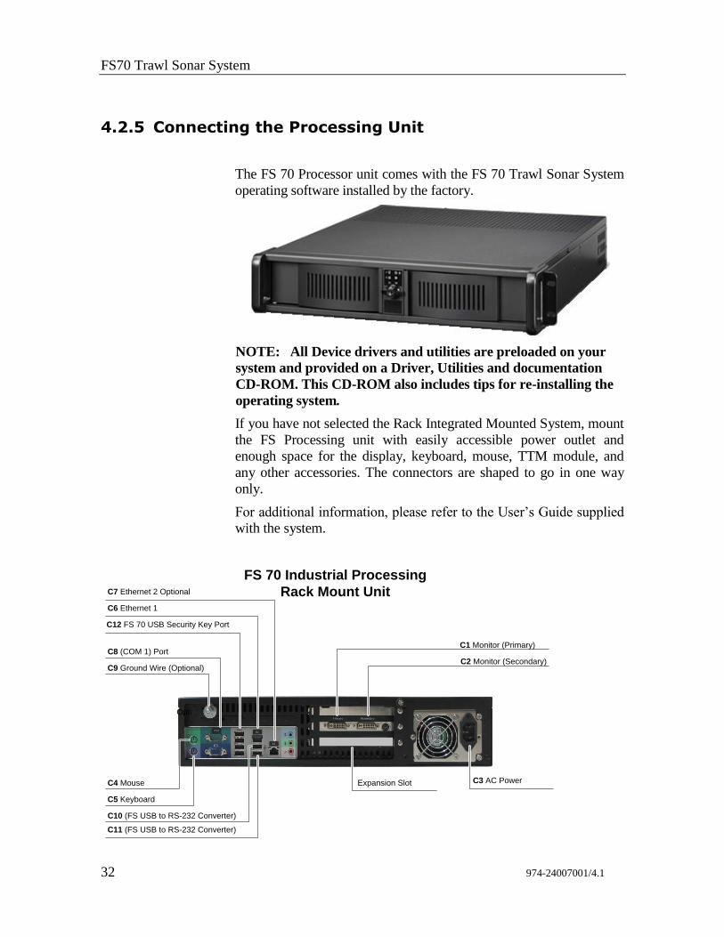
4.2.5 Connecting the Processing Unit
The FS 70 Processor unit comes with the FS 70 Trawl Sonar System
operating software installed by the factory.
NOTE: All Device drivers and utilities are preloaded on your
system and provided on a Driver, Utilities and documentation
CD-ROM. This CD-ROM also includes tips for re-installing the
operating system.
If you have not selected the Rack Integrated Mounted System, mount
the FS Processing unit with easily accessible power outlet and
enough space for the display, keyboard, mouse, TTM module, and
any other accessories. The connectors are shaped to go in one way
only.
For additional information, please refer to the User’s Guide supplied
with the system.
C6 Ethernet 1
C7 Ethernet 2 Optional
C3 AC PowerC4 Mouse
C5 Keyboard
C1 Monitor (Primary)
C2 Monitor (Secondary)
C10 (FS USB to RS-232 Converter)
C9 Ground Wire (Optional)
C8 (COM 1) Port
Opti
C12 FS 70 USB Security Key Port
C11 (FS USB to RS-232 Converter)
Expansion Slot
FS 70 Industrial Processing
Rack Mount Unit
FS 70 Installation Instructions
974-24007001/4.1 33
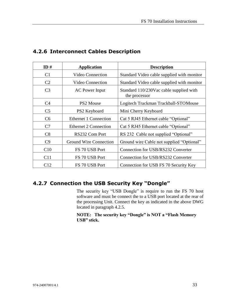
4.2.6 Interconnect Cables Description
ID # Application Description
C1 Video Connection Standard Video cable supplied with monitor
C2 Video Connection Standard Video cable supplied with monitor
C3 AC Power Input Standard 110/230Vac cable supplied with
the processor
C4 PS2 Mouse Logitech Trackman Trackball-STO Mouse
C5 PS2 Keyboard Mini Cherry Keyboard
C6 Ethernet 1 Connection Cat 5 RJ45 Ethernet cable “Optional”
C7 Ethernet 2 Connection Cat 5 RJ45 Ethernet cable “Optional”
C8 RS232 Com Port RS 232 Cable not supplied “Optional”
C9 Ground Wire Connection Ground wire Cable not supplied “Optional”
C10 FS 70 USB Port Connection for USB/RS232 Converter
C11 FS 70 USB Port Connection for USB/RS232 Converter
C12 FS 70 USB Port Connection for USB FS 70 Security Key
4.2.7 Connection the USB Security Key “Dongle”
The security key “USB Dongle” is require to run the FS 70 host
software and must be connect the to a USB port located at the rear of
the processing Unit. Connect the key as indicated in the above DWG
located in paragraph 4.2.5.
NOTE: The security key “Dongle” is NOT a “Flash Memory
USB” stick.
FS70 Trawl Sonar System
34 974-24007001/4.1
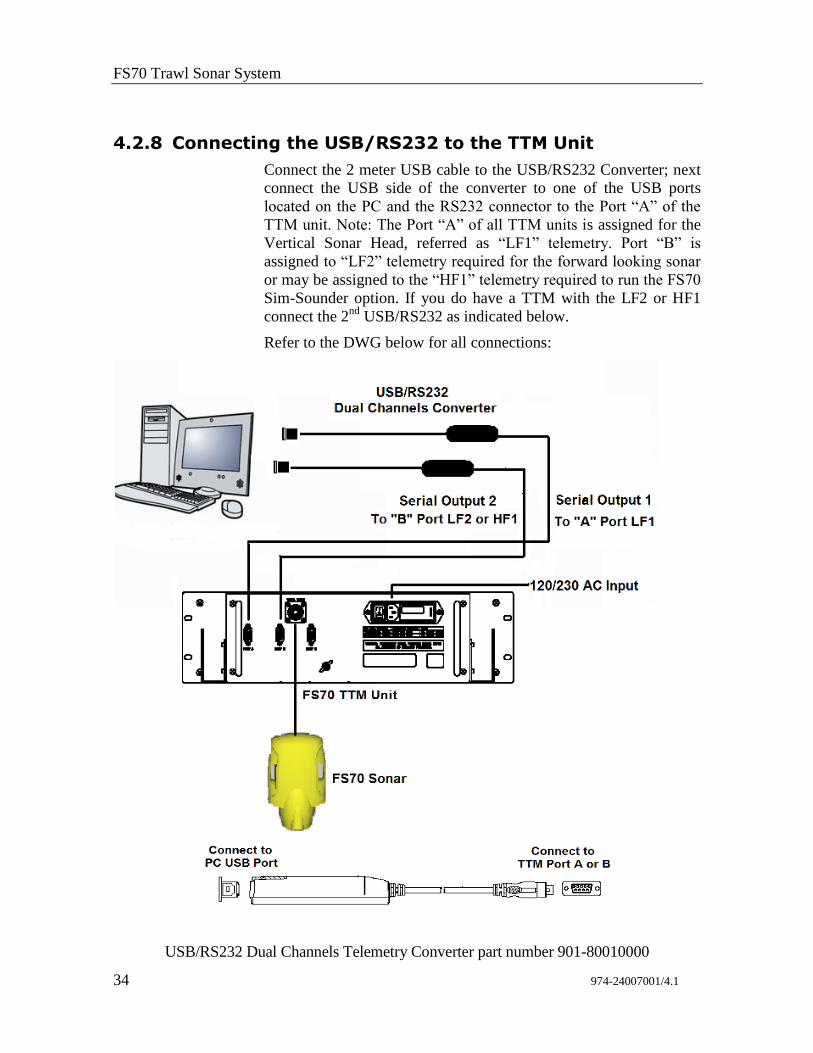
4.2.8 Connecting the USB/RS232 to the TTM Unit
Connect the 2 meter USB cable to the USB/RS232 Converter; next
connect the USB side of the converter to one of the USB ports
located on the PC and the RS232 connector to the Port “A” of the
TTM unit. Note: The Port “A” of all TTM units is assigned for the
Vertical Sonar Head, referred as “LF1” telemetry. Port “B” is
assigned to “LF2” telemetry required for the forward looking sonar
or may be assigned to the “HF1” telemetry required to run the FS70
Sim-Sounder option. If you do have a TTM with the LF2 or HF1
connect the 2nd
USB/RS232 as indicated below.
Refer to the DWG below for all connections:
USB/RS232 Dual Channels Telemetry Converter part number 901-80010000
FS 70 Installation Instructions
974-24007001/4.1 35
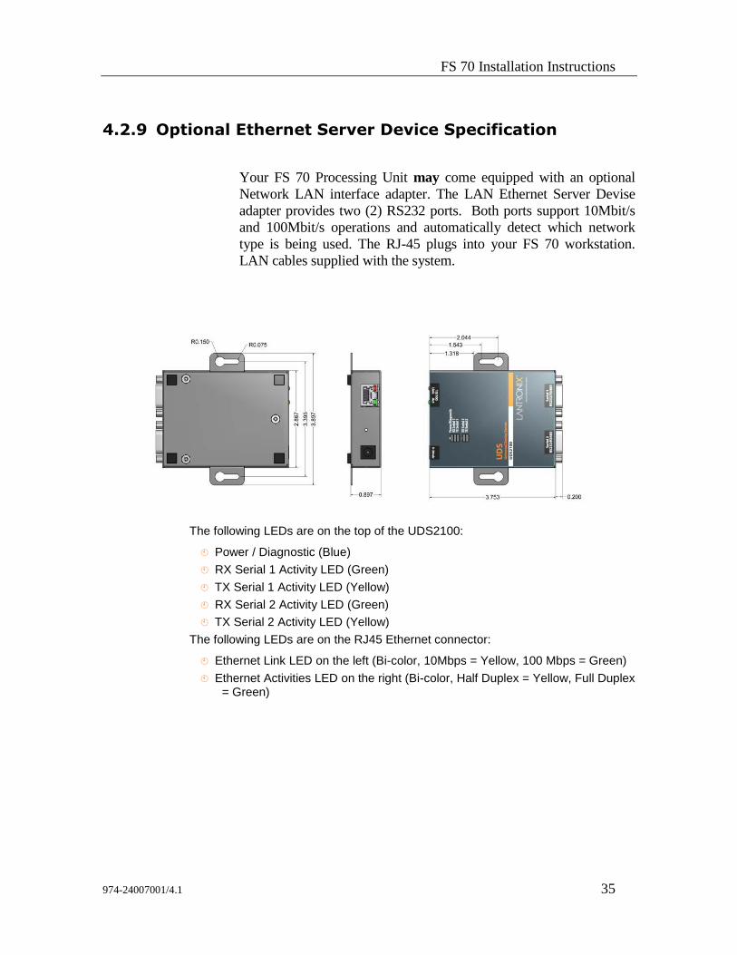
4.2.9 Optional Ethernet Server Device Specification
Your FS 70 Processing Unit may come equipped with an optional
Network LAN interface adapter. The LAN Ethernet Server Devise
adapter provides two (2) RS232 ports. Both ports support 10Mbit/s
and 100Mbit/s operations and automatically detect which network
type is being used. The RJ-45 plugs into your FS 70 workstation.
LAN cables supplied with the system.
The following LEDs are on the top of the UDS2100:
Power / Diagnostic (Blue)
RX Serial 1 Activity LED (Green)
TX Serial 1 Activity LED (Yellow)
RX Serial 2 Activity LED (Green)
TX Serial 2 Activity LED (Yellow)
The following LEDs are on the RJ45 Ethernet connector:
Ethernet Link LED on the left (Bi-color, 10Mbps = Yellow, 100 Mbps = Green)
Ethernet Activities LED on the right (Bi-color, Half Duplex = Yellow, Full Duplex = Green)
FS70 Trawl Sonar System
36 974-24007001/4.1
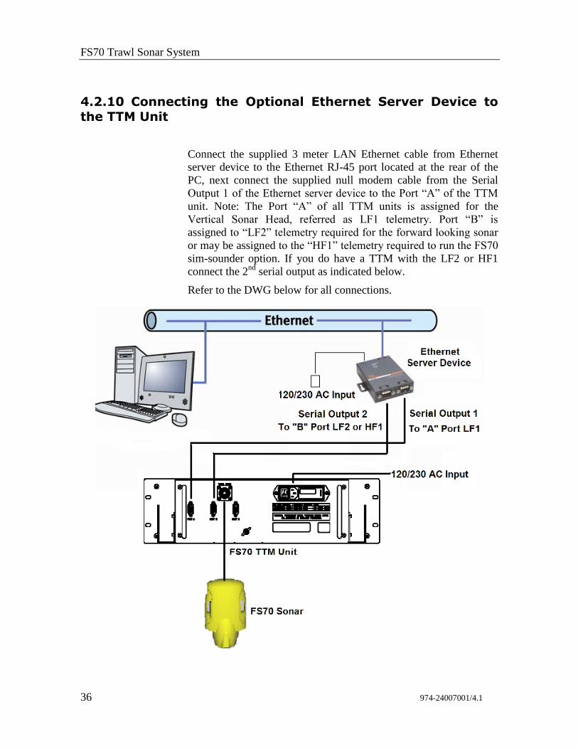
4.2.10 Connecting the Optional Ethernet Server Device to
the TTM Unit
Connect the supplied 3 meter LAN Ethernet cable from Ethernet
server device to the Ethernet RJ-45 port located at the rear of the
PC, next connect the supplied null modem cable from the Serial
Output 1 of the Ethernet server device to the Port “A” of the TTM
unit. Note: The Port “A” of all TTM units is assigned for the
Vertical Sonar Head, referred as LF1 telemetry. Port “B” is
assigned to “LF2” telemetry required for the forward looking sonar
or may be assigned to the “HF1” telemetry required to run the FS70
sim-sounder option. If you do have a TTM with the LF2 or HF1
connect the 2nd
serial output as indicated below.
Refer to the DWG below for all connections.
FS 70 Installation Instructions
974-24007001/4.1 37
4.2.11 Connecting a GPS
The GPS NMEA 183 output can be connected to the serial port at the
rear of the processing unit. The interconnect cable is not supplied.
The pin connections for your GPS input/output PC/RS232 are as
follows:
Pin number “2” - 232 Rx,
Pin number “3” - 232 Tx,
Pin number “5” - GND.
4.2.12 Connecting a Echo Sounder
The FS 70 Processor Unit may be connected to an echo sounder for
display of the trawl unit depth on the sounder. This is made via the
RS232 serial port on the rear panel of the processing unit or an
RS232/USB converter. The processor will output the Temperature
and the Depth from the trawl integrated sensor module in the
NMEA 0183 format.
If port “B” is not available you will have to install an additional
serial card or install an RS232/USB external converter.
4.2.13 Connecting a Heading Sensor
If you need to connect a heading sensor output to the serial port at the
rear of the processing unit, you will have to install an additional serial
card in the Processing Unit or install an RS232/USB external
converter. The pinout for your heading sensor input/output RS232
connection is as follows:
Pin number “2” 232 Rx,
Pin number “3” 232 Tx,
Pin number “5” GND.
For additional information, please refer to the User’s Guide supplied
with the system.
FS70 Trawl Sonar System
38 974-24007001/4.1
4.2.14 Connection to Cable Winch/Slip-Rings
The connection between the FS TTM Interface unit and the cable
winch/slip-rings should be made with a 12AWG or heavier,
shielded pair cable. The connection to the control unit is made using
the 3-pin MS connector supplied in the TTM module accessory kit.
To minimize noise interference on the cable, the shield of the cable
should be attached to the connector.
NOTES:
1. The shield of the cable between the FS TTM module and the
slip-rings should be connected at the TTM module, but NOT
at the slip-rings.
2. Based on experience from previous installations, good
results were achieved using a section of your 3rd wire cable
for this connection.
4.2.15 Assembling of the Trawl Unit
Assembling the trawl unit for the first time should be conducted in
the wheel house where the surface unit electronics have been
mounted. This will facilitate testing the trawl unit using the test
cable.
4.2.16 FS 70 Configuration
The FS 70 trawl configurations all consist of an FS 70, 120 kHz or
330 kHz vertical sonar head with a 200 kHz echo sounder, an FS 70
sensor module is integrated in the trawl sonar head. The FS 70
polyurethane housing includes mounting and assembling hardware
and a strain relief. The trawl unit also contains a catch receiver unit
and the echo sounder transducer. Assembly of the unit involves
correctly locating the sonar head, attaching the strain relief to the
trawl cable, proper routing and connection of the cable to the sonar
head and bolting the polyurethane housing together. This section
describes the connection and location of the sonar head, echo
sounder transducer and catch receive transducer. Final assembly is
illustrated in the “Drawings” section.
FS 70 Installation Instructions
974-24007001/4.1 39
A locating block located at the end of the housing or a guide bracket
is used to prevent the sonar head from rotating. Only one guide
block is required and it can be placed into the positioning hole of the
bottom half of the trawl unit housing as shown in the assembly
drawing in Chapter 6.
NOTE: Dow Corning “#55” grease must be applied to all
mating surfaces of underwater connectors to insure proper
sealing. Sufficient grease should be applied so that excess
squeezes out with any air when the connectors are mated. RTV
or any other sealant must NOT be used, and when tightening
the locking sleeves, do NOT use a wrench or pliers!
4.3 System Set-up and Testing using the test cable
Initial power-up, set-up and test of the system should be made with
the trawl unit connected to the PWR/TTM module using the
supplied test cable. The 3-pin MS connector of the test cable is
attached to the connector labelled “TEST CABLE” located on the
front panel of the PWR/TTM unit. The other end of the test cable is
plugged into the 2-pin connector on the sonar head of the trawl unit.
4.3.1 FS Processor & TTM Communication set-Up
The commnunication between the FS Processor and the TTM unit
can be achive 3 ways depending on the type of communication
ports available in the processor unit:
1. If standard serial COM ports are available you may use a RS232
Null Modem cable, KML part number 144-0217, supplied with the
processor.
2. If USB ports are available then use the USB/RS232 telemetry
converter, KML part number 901-80010000, supplied with the
processor.
3. If the Ethernet port is desirable for communication then the
Ethernet/RS232 Server kit, KML part number 422-42140000, can
be purchased as an option.
4.3.2 Optional Ethernet Processor System Set-Up
Setting up your surface Window Processor to communicate with the
Ethernet converter, static “IP” addresses and “Subnet Mask” are
used to communicate between the processor and the Ethernet
converter.
IP Adress: 192.168.000.XX
Subnet Mask: 255.255.255.00
FS70 Trawl Sonar System
40 974-24007001/4.1
Where “X” is a decimal number between 1 and 254, the number
“0” and “255” are reserved numbers to set-up the static “IP”
adresses.
To set-up your computer Ethernet adapter “IP” address.
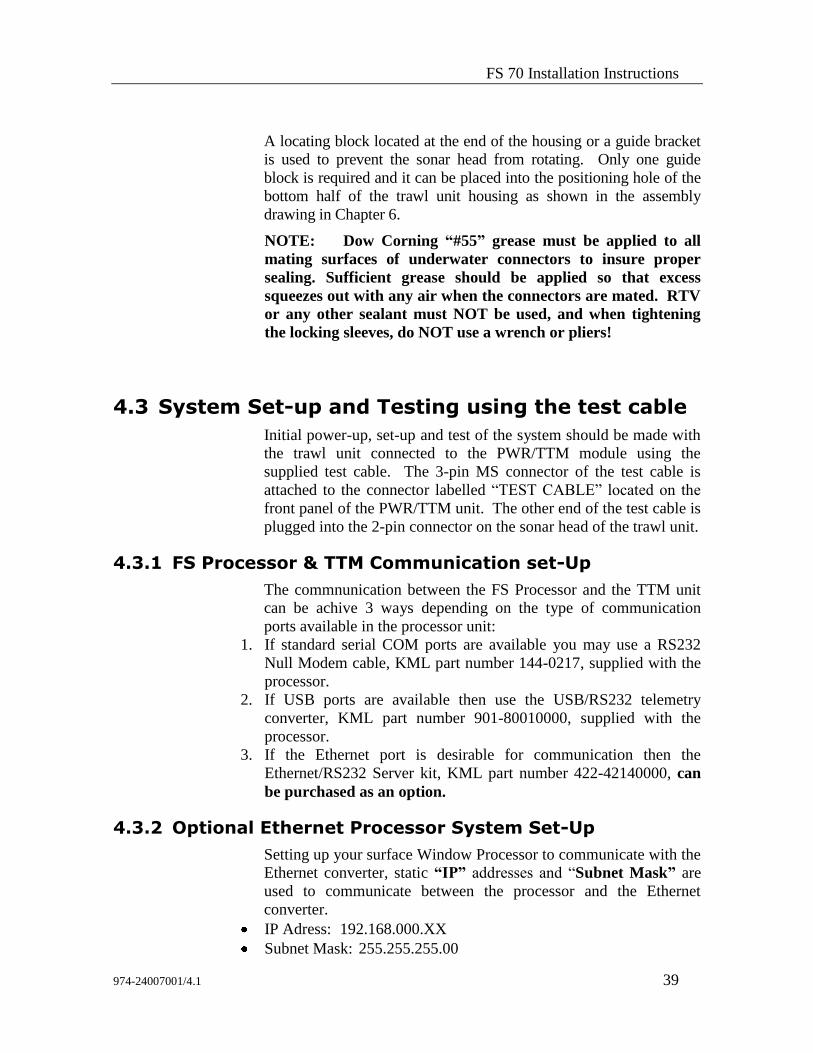
On your computer desktop, click Start> Control Panel> next
double left click on Network Connection. The following window
below will pop-up.
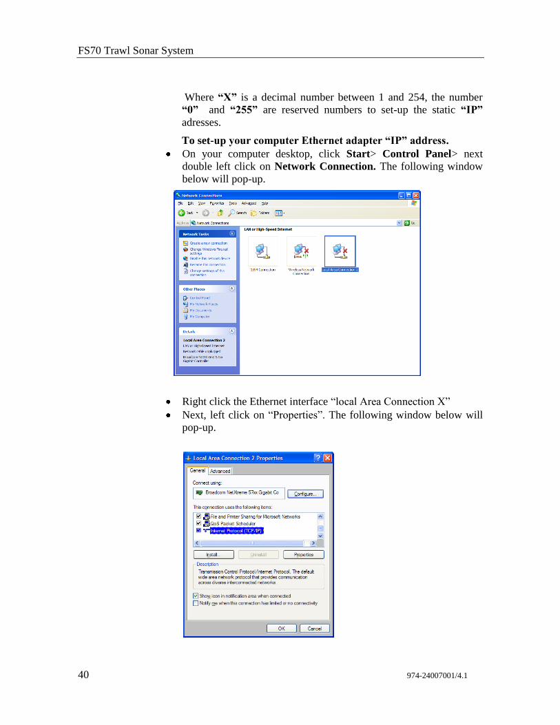
Right click the Ethernet interface “local Area Connection X”
Next, left click on “Properties”. The following window below will
pop-up.
FS 70 Installation Instructions
974-24007001/4.1 41
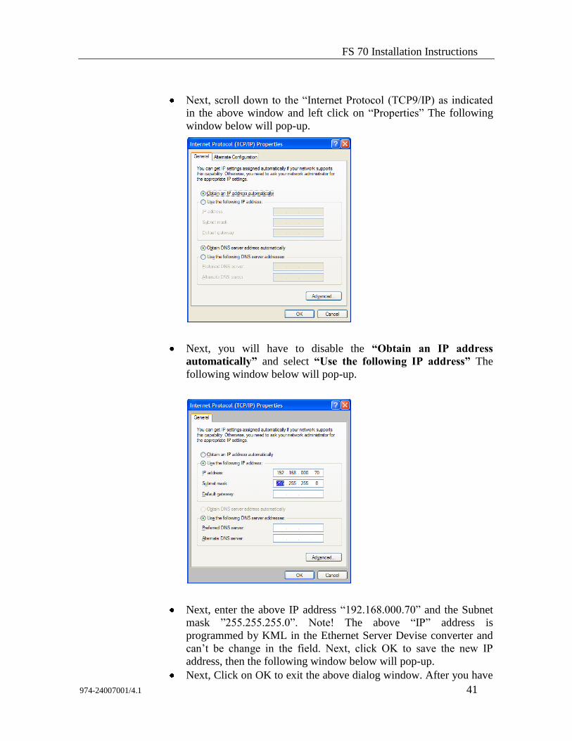
Next, scroll down to the “Internet Protocol (TCP9/IP) as indicated
in the above window and left click on “Properties” The following
window below will pop-up.
Next, you will have to disable the “Obtain an IP address
automatically” and select “Use the following IP address” The
following window below will pop-up.
Next, enter the above IP address “192.168.000.70” and the Subnet
mask ”255.255.255.0”. Note! The above “IP” address is
programmed by KML in the Ethernet Server Devise converter and
can’t be change in the field. Next, click OK to save the new IP
address, then the following window below will pop-up.
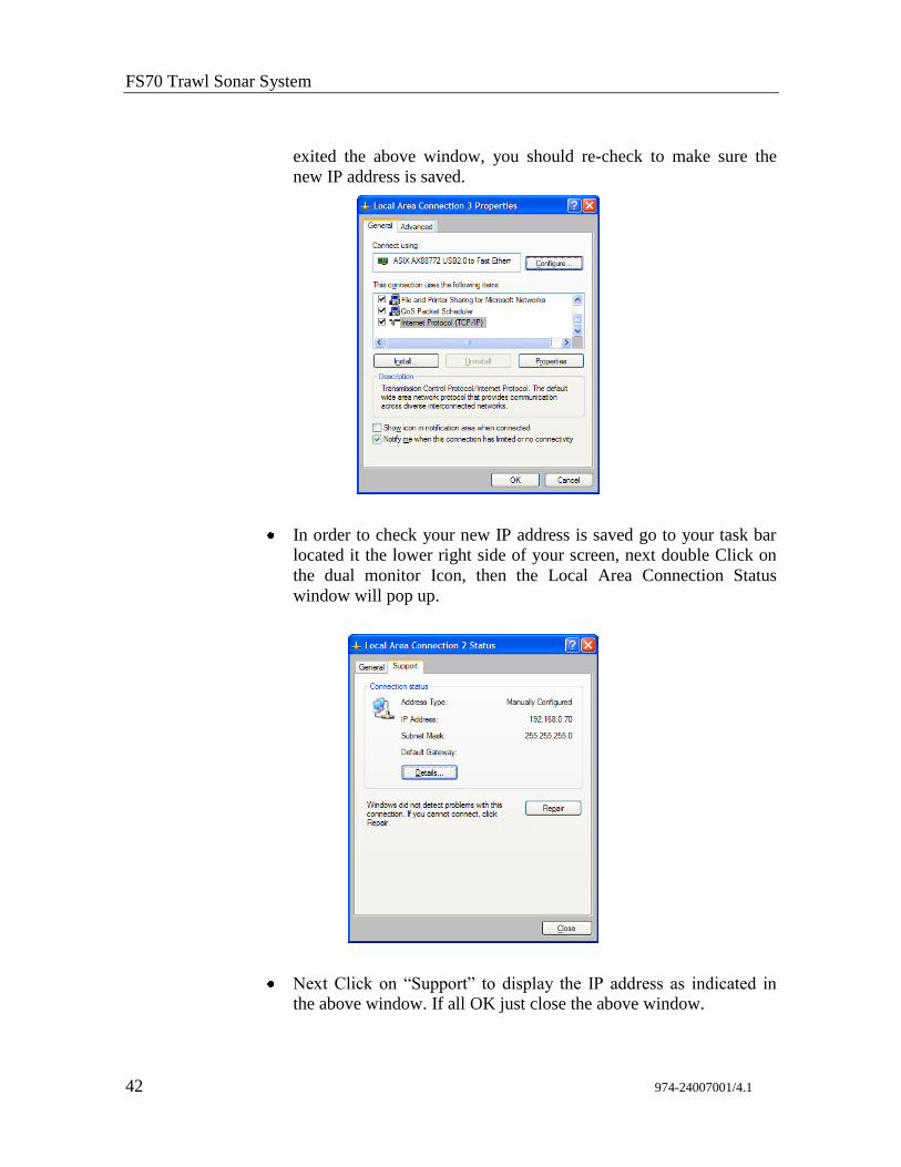
Next, Click on OK to exit the above dialog window. After you have
FS70 Trawl Sonar System
42 974-24007001/4.1
exited the above window, you should re-check to make sure the
new IP address is saved.
In order to check your new IP address is saved go to your task bar
located it the lower right side of your screen, next double Click on
the dual monitor Icon, then the Local Area Connection Status
window will pop up.
Next Click on “Support” to display the IP address as indicated in
the above window. If all OK just close the above window.
FS 70 Installation Instructions
974-24007001/4.1 43
4.3.3 Security Firewall Protection System Set-Up
The Firewall protection is an important part of the processor unit.
There is no problem in having the security protection disabled
providing the processor in not connected to any outside provider
“Ethernet” or connected to a central internal “Hub” system.
We recommend that the “Firewall” protection be ENABLE at all
times. The following chapter will explain the proper procedure to
Disable/Enable the firewall protection.
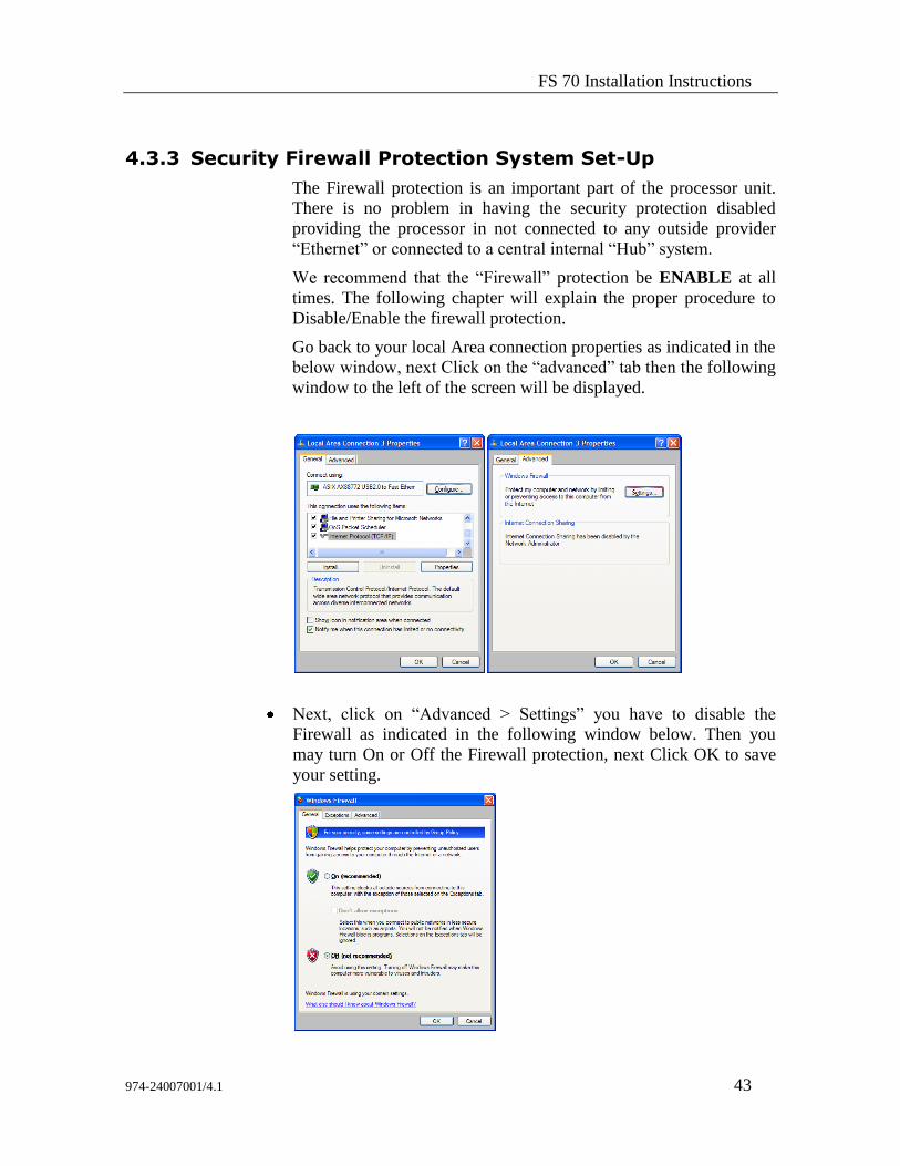
Go back to your local Area connection properties as indicated in the
below window, next Click on the “advanced” tab then the following
window to the left of the screen will be displayed.
Next, click on “Advanced > Settings” you have to disable the
Firewall as indicated in the following window below. Then you
may turn On or Off the Firewall protection, next Click OK to save
your setting.
FS70 Trawl Sonar System
44 974-24007001/4.1
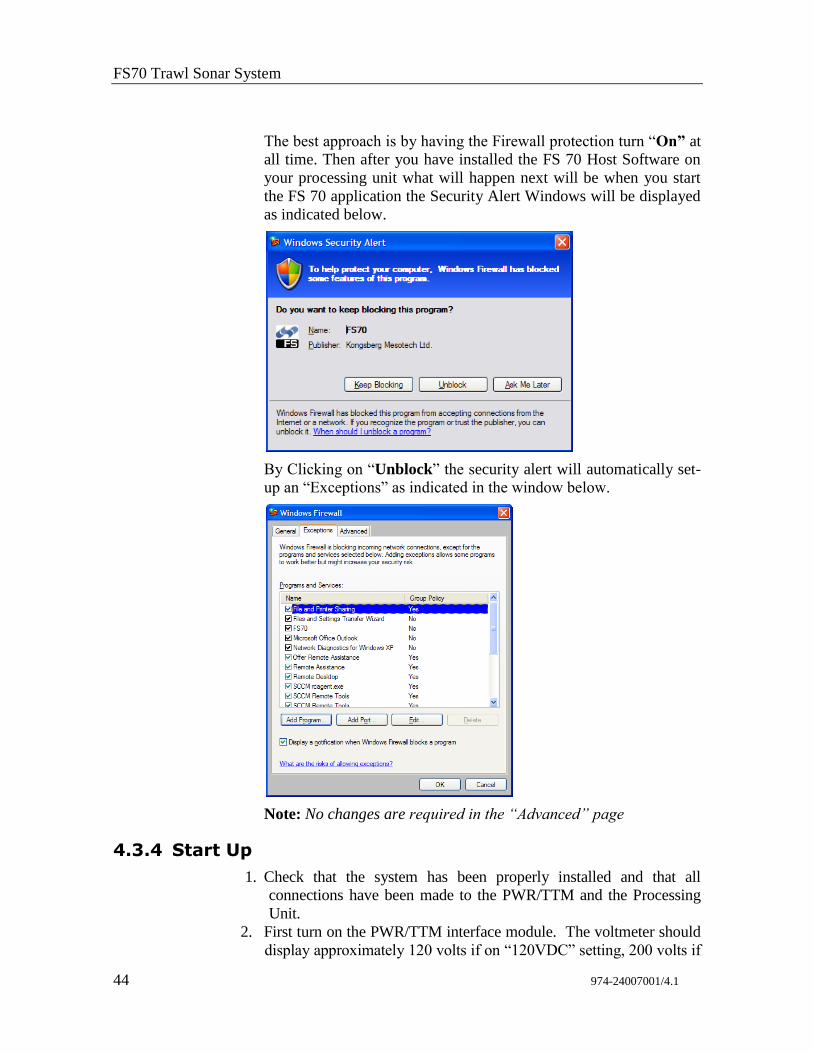
The best approach is by having the Firewall protection turn “On” at
all time. Then after you have installed the FS 70 Host Software on
your processing unit what will happen next will be when you start
the FS 70 application the Security Alert Windows will be displayed
as indicated below.
By Clicking on “Unblock” the security alert will automatically set-
up an “Exceptions” as indicated in the window below.
Note: No changes are required in the “Advanced” page
4.3.4 Start Up
1. Check that the system has been properly installed and that all
connections have been made to the PWR/TTM and the Processing
Unit.
2. First turn on the PWR/TTM interface module. The voltmeter should
display approximately 120 volts if on “120VDC” setting, 200 volts if
FS 70 Installation Instructions
974-24007001/4.1 45
on the “200VDC” setting and approximately 60 volts if on “TEST”
setting. The current meter should read approximately 0.15 – 0.7
amps.
3. Next turn on the display monitor, and then turn on the processing
unit. The system will start up automatically.
4.3.5 Power-Up Configuration
For the system to operate properly the trawl unit configuration must
be selected correctly. In addition, modification of these power-up
configuration parameters is done in a special mode selected after
power-up of the Processor unit.
The following sections describe the process of configuring these
parameters. These steps must be followed only when the system is
powered-up for the first time or when you have to replace the
Processing unit or the TTM Module assembly.
4.3.6 Selecting the Trawl Output Voltage
You must select the proper trawl voltage in accordance with the
under water trawl unit system you are using,
In the “OFF” position, no voltage is applied to the trawl cable.
In the “TEST” position, 60 VDC will be provided to the trawl cable.
Note: The “TEST” position is provided for the old FS 3300, 1000
meter sonar head. You must connect the test cable supplied with the
system to the front panel connector of the TTM marked “TEST
CABLE” and position the Trawl/Test switch located on the front
panel of the TTM module to “TEST”.
In the “120 V” position, 120 VDC will be provided to the trawl
cable. The 120 VDC is provided to run all FS3300, 1800 meter sonar
head. The same procedure should be used to test an FS3300 1800
meter head.
In the “200V” position, 200VDC will be provided to the trawl cable.
The 200VDC is provided to run all TS10, TS15, TS15S and the FS70
sonar heads.
NOTE: To test a TS10, TS15, TS15S and FS70 sonar head
position the trawl voltage switch to 120 VDC, connect the test
cable supplied with the system to the front panel connector
marked “TEST CABLE” and position the Trawl/Test switch
located on the front panel of the TTM Interface Unit to
“TEST”.
WARNING: Make sure you have selected the trawl voltage for
the appropriate sonar head before turning power ON.
FS70 Trawl Sonar System
46 974-24007001/4.1
4.3.7 FS 70 Start-up Procedure
For the purpose of demonstrating the Start-up Procedure in this
chapter, we are using the recommended Processing Unit that has 2
COM Ports, COM 1 and COM 3. The COM 1 and COM 3 Ports
from the Processing Unit are not connected to the FS TTM module
RS 232 port “A”. No communication will be made from the COM 1
or COM 3 to the TTM module. We will be using an RS232/USB
telemetry converter “KML-USB1” connected to the “A” port of the
TTM module
We will be using an FS 70, 120 kHz/40 kHz Catch Trawl Sonar
Head with the 200 kHz net sounder option with the integrated
sensor module.
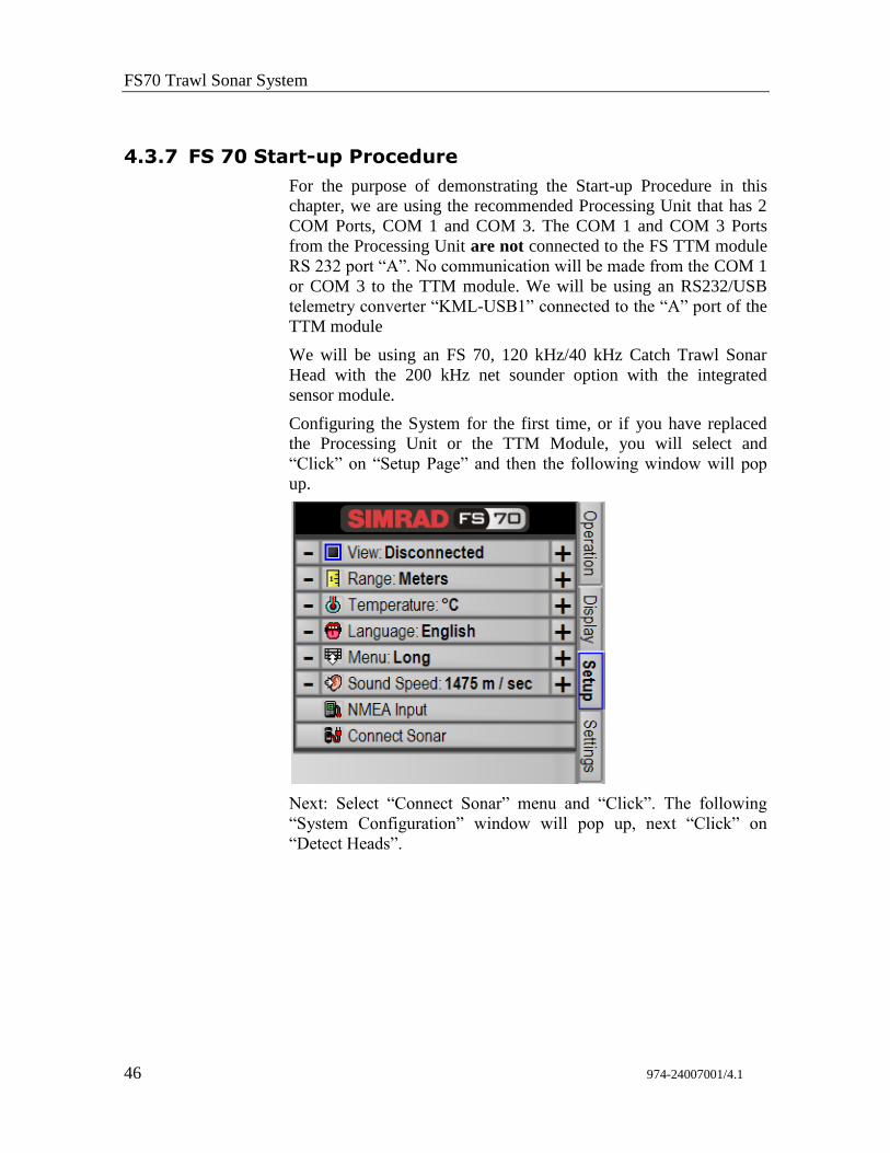
Configuring the System for the first time, or if you have replaced
the Processing Unit or the TTM Module, you will select and
“Click” on “Setup Page” and then the following window will pop
up.
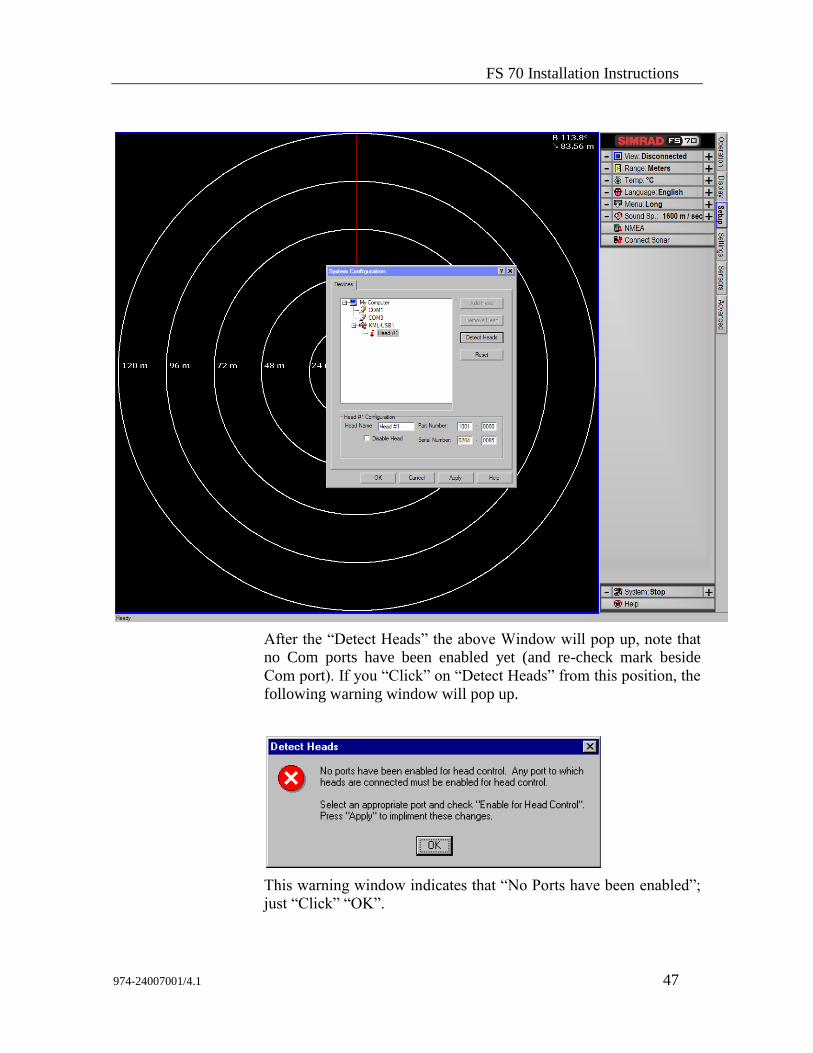
Next: Select “Connect Sonar” menu and “Click”. The following
“System Configuration” window will pop up, next “Click” on
“Detect Heads”.
FS 70 Installation Instructions
974-24007001/4.1 47
After the “Detect Heads” the above Window will pop up, note that
no Com ports have been enabled yet (and re-check mark beside
Com port). If you “Click” on “Detect Heads” from this position, the
following warning window will pop up.
This warning window indicates that “No Ports have been enabled”;
just “Click” “OK”.
FS70 Trawl Sonar System
48 974-24007001/4.1
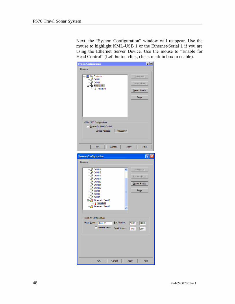
Next, the “System Configuration” window will reappear. Use the
mouse to highlight KML-USB 1 or the Ethernet/Serial 1 if you are
using the Ethernet Server Device. Use the mouse to “Enable for
Head Control” (Left button click, check mark in box to enable).
FS 70 Installation Instructions
974-24007001/4.1 49
“Click” on “Apply”. The following window will appear, overlaying
the above window, asking you to reboot the computer. Just “Click”
“OK” and do not “Reboot the computer now”; “Click” “OK” in the
“System Configuration” window.
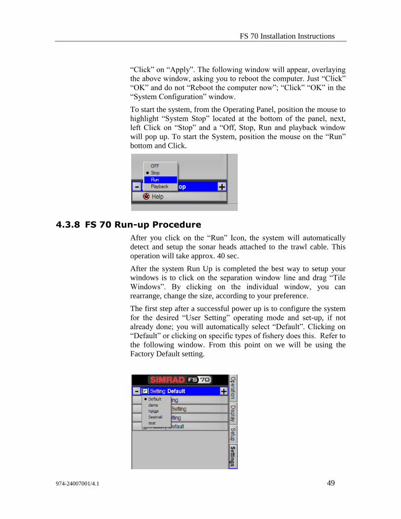
To start the system, from the Operating Panel, position the mouse to
highlight “System Stop” located at the bottom of the panel, next,
left Click on “Stop” and a “Off, Stop, Run and playback window
will pop up. To start the System, position the mouse on the “Run”
bottom and Click.
4.3.8 FS 70 Run-up Procedure
After you click on the “Run” Icon, the system will automatically
detect and setup the sonar heads attached to the trawl cable. This
operation will take approx. 40 sec.
After the system Run Up is completed the best way to setup your
windows is to click on the separation window line and drag “Tile
Windows”. By clicking on the individual window, you can
rearrange, change the size, according to your preference.
The first step after a successful power up is to configure the system
for the desired “User Setting” operating mode and set-up, if not
already done; you will automatically select “Default”. Clicking on
“Default” or clicking on specific types of fishery does this. Refer to
the following window. From this point on we will be using the
Factory Default setting.
FS70 Trawl Sonar System
50 974-24007001/4.1
By clicking on the “Vertical Window” of the Sounder Window you
will have control over the selected Sonar. The sonar you have
selected will be highlighted by a blue bar across the top.
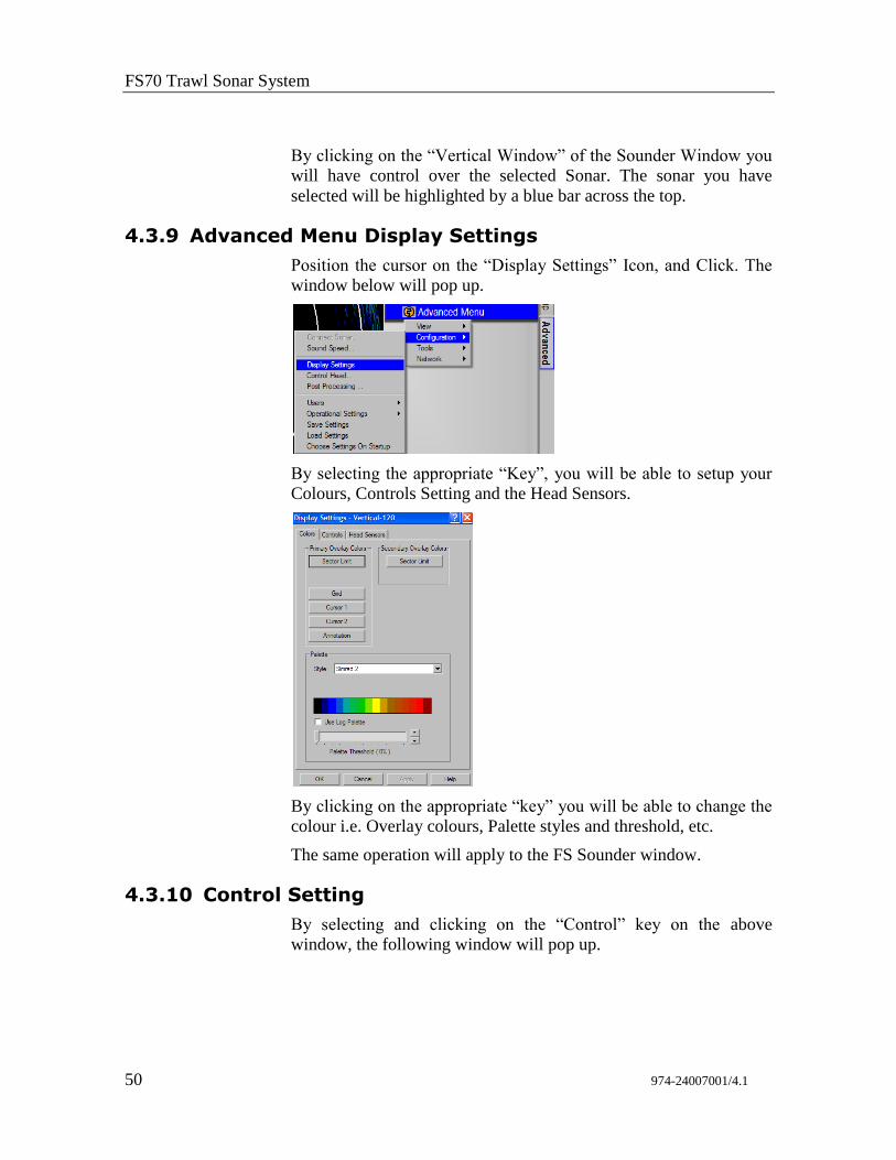
4.3.9 Advanced Menu Display Settings
Position the cursor on the “Display Settings” Icon, and Click. The
window below will pop up.
By selecting the appropriate “Key”, you will be able to setup your
Colours, Controls Setting and the Head Sensors.
By clicking on the appropriate “key” you will be able to change the
colour i.e. Overlay colours, Palette styles and threshold, etc.
The same operation will apply to the FS Sounder window.
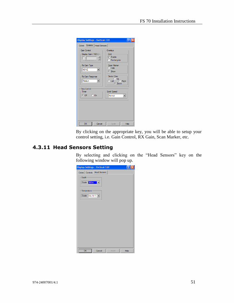
4.3.10 Control Setting
By selecting and clicking on the “Control” key on the above
window, the following window will pop up.
FS 70 Installation Instructions
974-24007001/4.1 51
By clicking on the appropriate key, you will be able to setup your
control setting, i.e. Gain Control, RX Gain, Scan Marker, etc.
4.3.11 Head Sensors Setting
By selecting and clicking on the “Head Sensors” key on the
following window will pop up.
FS70 Trawl Sonar System
52 974-24007001/4.1
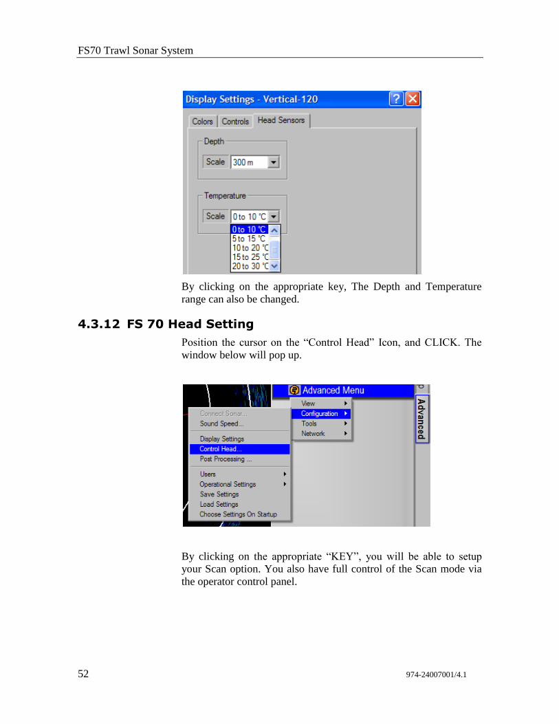
By clicking on the appropriate key, The Depth and Temperature
range can also be changed.
4.3.12 FS 70 Head Setting
Position the cursor on the “Control Head” Icon, and CLICK. The
window below will pop up.
By clicking on the appropriate “KEY”, you will be able to setup
your Scan option. You also have full control of the Scan mode via
the operator control panel.
FS 70 Installation Instructions
974-24007001/4.1 53
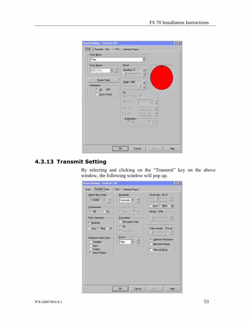
4.3.13 Transmit Setting
By selecting and clicking on the “Transmit” key on the above
window, the following window will pop up.
FS70 Trawl Sonar System
54 974-24007001/4.1
By clicking on the appropriate key, you will be able to setup your
Transmitter configuration in order to optimize fish detection. The
same operation will apply to the FS Sounder Window.
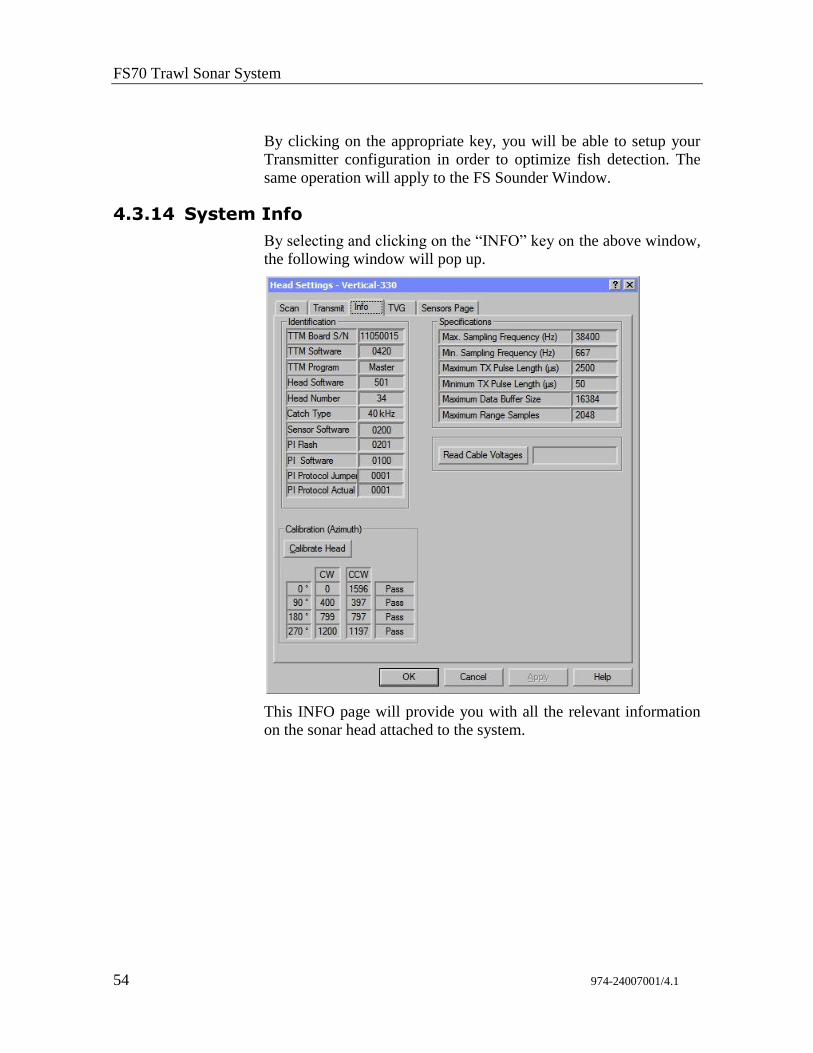
4.3.14 System Info
By selecting and clicking on the “INFO” key on the above window,
the following window will pop up.
This INFO page will provide you with all the relevant information
on the sonar head attached to the system.
FS 70 Installation Instructions
974-24007001/4.1 55
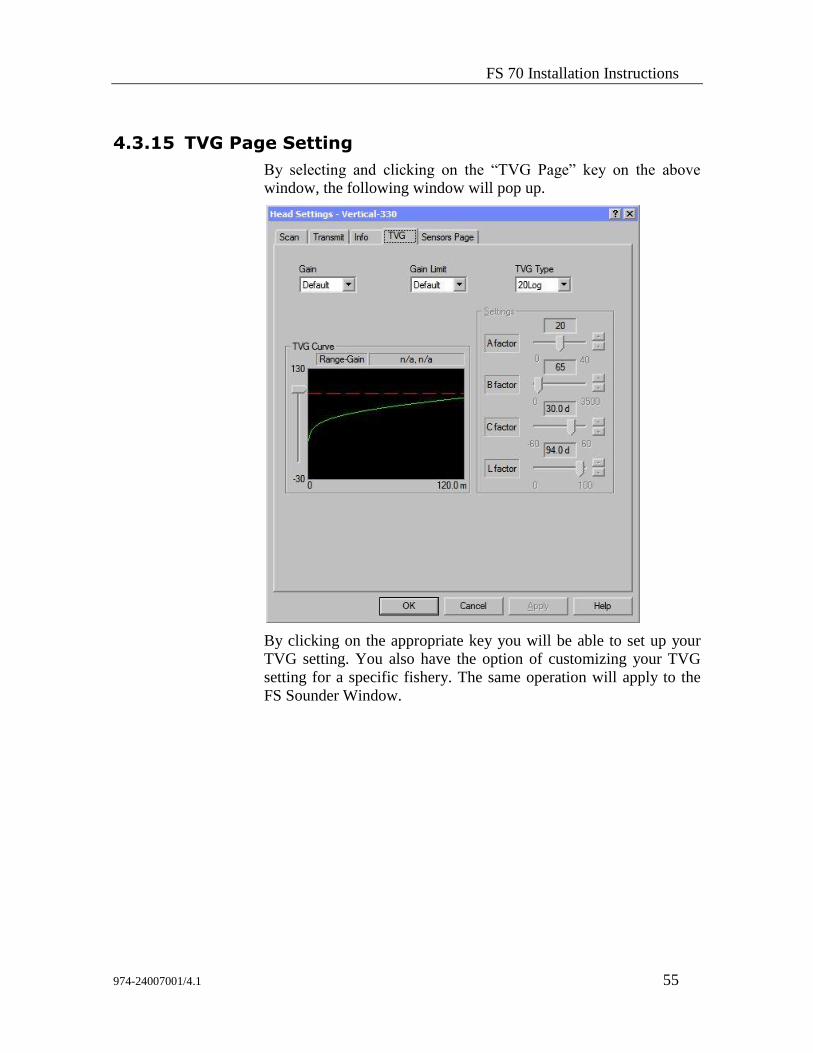
4.3.15 TVG Page Setting
By selecting and clicking on the “TVG Page” key on the above
window, the following window will pop up.
By clicking on the appropriate key you will be able to set up your
TVG setting. You also have the option of customizing your TVG
setting for a specific fishery. The same operation will apply to the
FS Sounder Window.
FS70 Trawl Sonar System
56 974-24007001/4.1
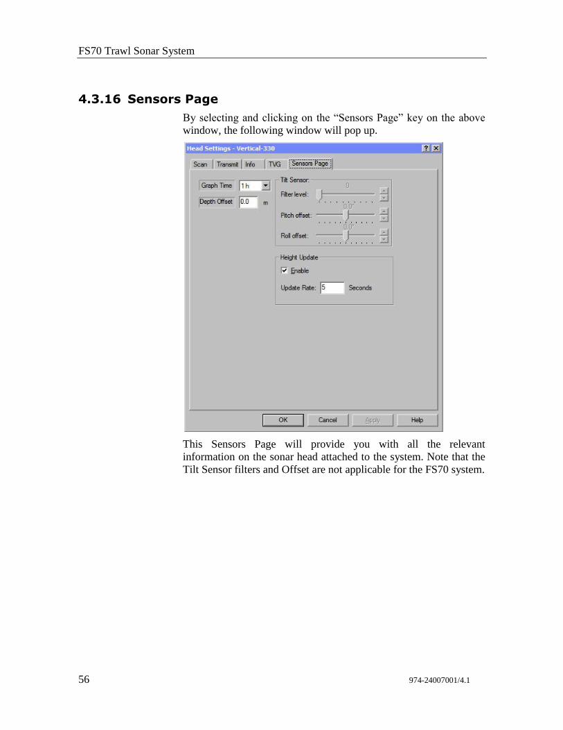
4.3.16 Sensors Page
By selecting and clicking on the “Sensors Page” key on the above
window, the following window will pop up.
This Sensors Page will provide you with all the relevant
information on the sonar head attached to the system. Note that the
Tilt Sensor filters and Offset are not applicable for the FS70 system.
FS 70 Installation Instructions
974-24007001/4.1 57
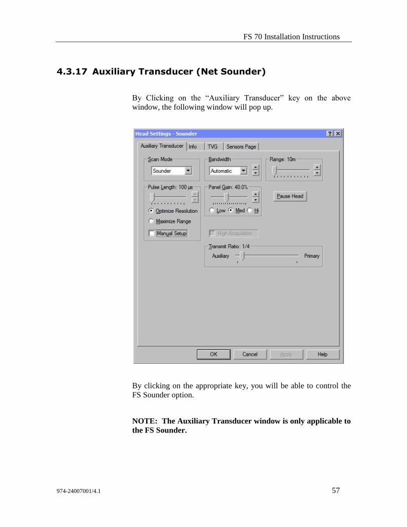
4.3.17 Auxiliary Transducer (Net Sounder)
By Clicking on the “Auxiliary Transducer” key on the above
window, the following window will pop up.
By clicking on the appropriate key, you will be able to control the
FS Sounder option.
NOTE: The Auxiliary Transducer window is only applicable to
the FS Sounder.
FS70 Trawl Sonar System
58 974-24007001/4.1
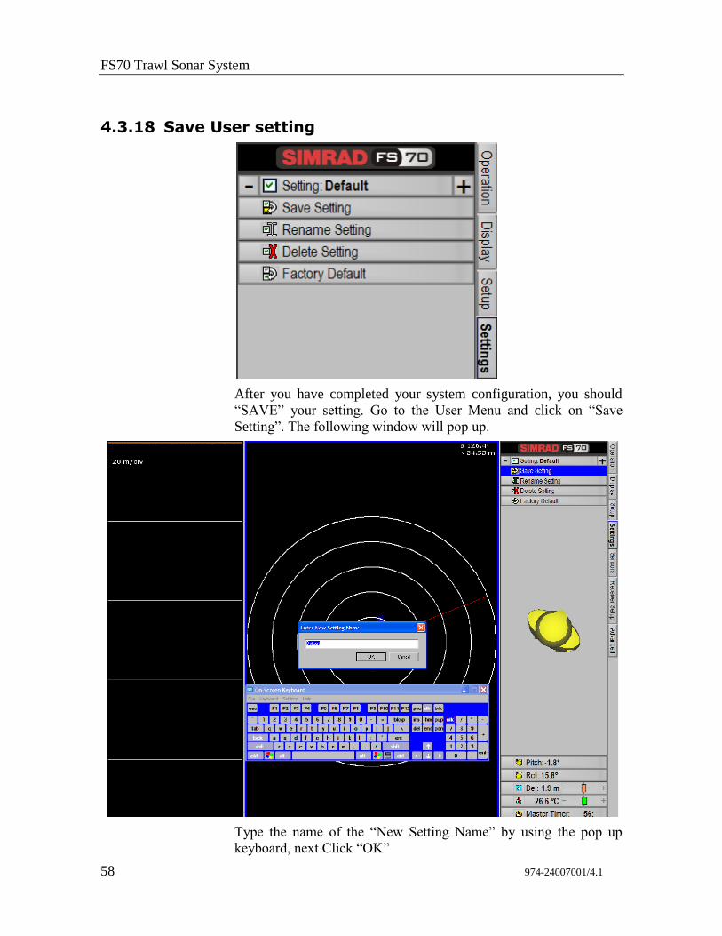
4.3.18 Save User setting
After you have completed your system configuration, you should
“SAVE” your setting. Go to the User Menu and click on “Save
Setting”. The following window will pop up.
Type the name of the “New Setting Name” by using the pop up
keyboard, next Click “OK”
FS 70 Installation Instructions
974-24007001/4.1 59
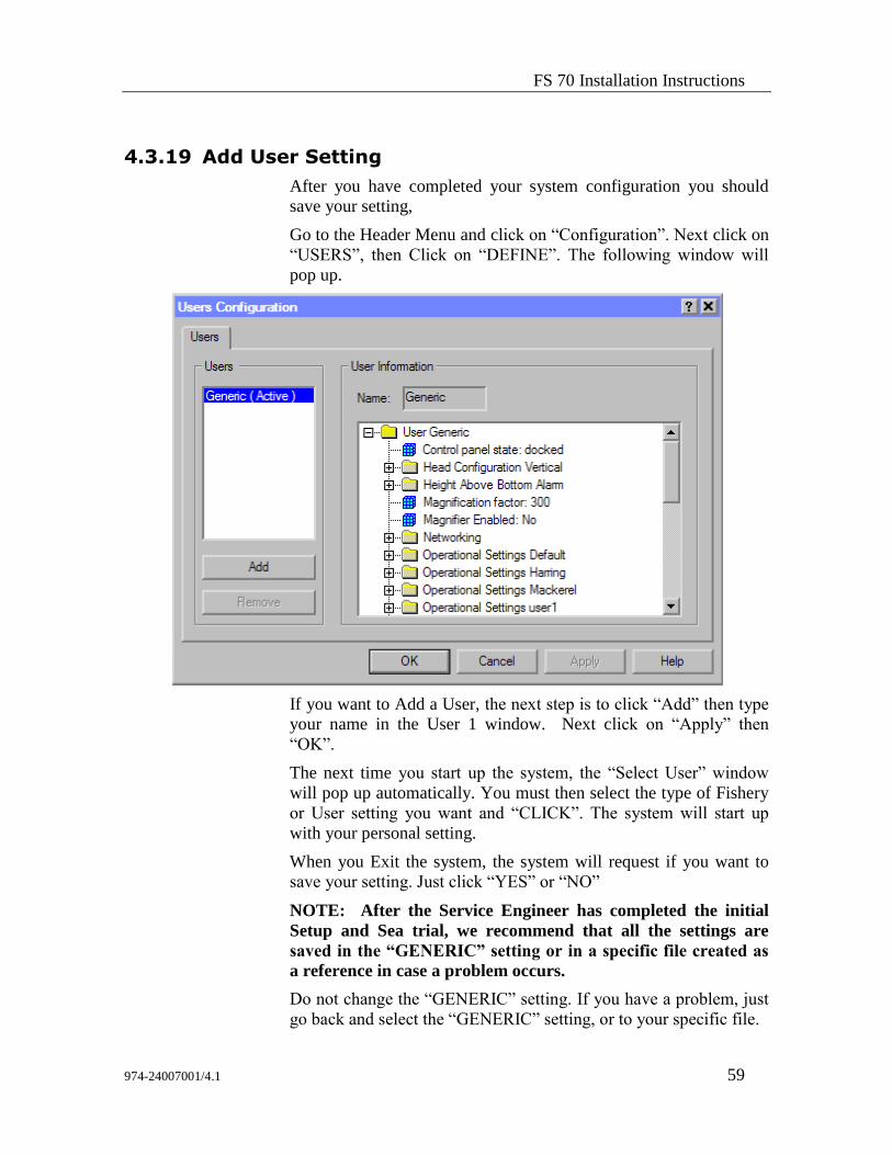
4.3.19 Add User Setting
After you have completed your system configuration you should
save your setting,
Go to the Header Menu and click on “Configuration”. Next click on
“USERS”, then Click on “DEFINE”. The following window will
pop up.
If you want to Add a User, the next step is to click “Add” then type
your name in the User 1 window. Next click on “Apply” then
“OK”.
The next time you start up the system, the “Select User” window
will pop up automatically. You must then select the type of Fishery
or User setting you want and “CLICK”. The system will start up
with your personal setting.
When you Exit the system, the system will request if you want to
save your setting. Just click “YES” or “NO”
NOTE: After the Service Engineer has completed the initial
Setup and Sea trial, we recommend that all the settings are
saved in the “GENERIC” setting or in a specific file created as
a reference in case a problem occurs.
Do not change the “GENERIC” setting. If you have a problem, just
go back and select the “GENERIC” setting, or to your specific file.
FS70 Trawl Sonar System
60 974-24007001/4.1
4.3.20 Final System Test
After preparing the trawl cable and before the final trawl unit
assembly a system test should be conducted to insure correct
operation of the FS 70 Trawl Monitoring System over the trawl
cable.
As before, the start- up procedures should be followed to power up
the system. Once the FS 70 has been turned on, the power supply
voltage and current meters should be examined. Expected values are
0.2 – 0.5 A, (output voltage selection switch should be set to
200VDC). If the voltage and current values differ significantly from
these values, it indicates a problem with the trawl cable or its
connections.
If there are any errors during the calibration a status report page will
appear containing the results that the control unit obtained from the
tests performed. Again, any errors will be due to the trawl cable or
its connections. Check the connections again and ensure that the
signal polarity at the trawl unit is correct. A DC voltmeter can be
used to check that the positive voltage is on the small pin of the
pigtail when the FS PWR/TTM unit is powered up.
If all is okay then the sonar head will begin scanning and the sonar
image display will appear.
4.3.21 Completing the Trawl Unit Assembly
First, the plastic cable strain relief supplied with the trawl unit must
be bolted to the trawl cable. The location should be at or very near
the pigtail splice, but NOT on the pigtail itself. You must slide the
rubber hose on the trawl cable, if used, down so that approximately
3.4 cm (1’.2") of the hose is clamped inside the strain relief.
Next, the trawl cable is connected to the sonar head. Liberal amounts
of Dow Corning #55 grease are applied to the connector surfaces
before mating so that a water tight seal is obtained. The locking
sleeve is then hand-tightened.
NOTE: Dow Corning “#55” grease must be applied to all
mating surfaces of underwater connectors to insure proper
sealing. Sufficient grease should be applied so that excess
squeezes out with any air when the connectors are mated. RTV
or any other sealant must NOT be used, and when tightening
the locking sleeves do NOT use a wrench or pliers!
FS 70 Installation Instructions
974-24007001/4.1 61
The plastic strain relief attached to the trawl cable is now placed in
the trawl unit housing containing the electronics and the excess cable
is routed in the housing. Care must be taken to insure that all cables
within the trawl unit housing are properly placed to avoid being
pinched and possibly damaged. The top half of the trawl unit
housing is then placed on top and the two halves are secured together
with the bolts supplied. Finally, the dome is secured over the
Vertical Sonar Head transducer with four additional bolts.
The fully assembled trawl unit is now ready for mounting to the trawl
head rope in the chosen manner.
4.3.22 Mounting the Catch Sensors
Proper mounting of the catch sensors on the cod-end is shown in
drawing # 830-056482.
The fill of the cod-end and the sensitivity of the sensors are
dependent upon the number of mesh knots between the catch sensor
and the rubber straps. Make sure that the sensor is mounted in the
correct direction with the transducer pointing towards the trawl unit
(the metal lid pointing aft).
WARNING: Make sure that the chains do not strain the net when
the cod-end is being filled with fish. This is controlled by
stretching the net to capacity in the direction which is relevant
AFTER THE SENSORS HAVE BEEN MOUNTED TO THE
TRAWL. The purpose of the chains is to prevent the sensor from
turning, and as an insurance against loss should the rubber straps
break. Mounting the chains too tight can result in the fastening
ears being ripped off.
If a system with four catch sensors has been ordered, sensors
numbered 1 and 2 can be used on the trawl and the other two sensors
kept for reserve.
For deep trawling, and when fish are abundant, it can be
advantageous to mount three or four catch indicators in such a way
that cod-end filling can be monitored continuously to insure that the
trawl is hauled back in time.
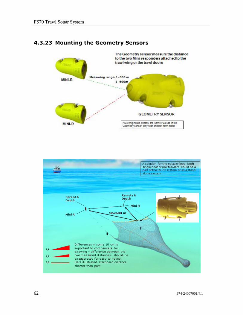
FS70 Trawl Sonar System
62 974-24007001/4.1
4.3.23 Mounting the Geometry Sensors
FS 70 Installation Instructions
974-24007001/4.1 63
The PI Geometry sensors are mounted behind the headrope at the
top of the trawl opening, or behind the footrope at the bottom
depending on the required application.
The two Mini-R responders are normally mounted in dedicated
adaptors on the two doors. They may also be mounted on the trawl
wings.
Communication link between the PI sensors and the two Mini-R
responders may be done via the FS 70 head rope unit forward
hydrophone located inside the DP housing or via the PI hydrophone
mounted below the ship hull.
Refer to the SIMRAD supplied PI Net Geometry Installation
Manual for additional information.
4.3.24 PI Receiver Basic Configuration Settings
When you put the PI Geometry to use, you must set it up with one
unique sensor number with two measurements. Only one update
rate can be chosen, this is common for both measurements. The
channel numbers are defined individually for the two
measurements.
Both the update rate and the channel numbers must be chosen
according to the sensor’s configuration. Write down this
configuration for future reference.
For default settings, to the SIMRAD supplied PI Net Geometry
Installation Manual table in section about sensor configuration.
If your PI system is fitted with MMI software version 0.50 and DSP
software version 1.11 or later, use the following recommended
receiver settings:
– Interference filter: On
– Interference filter level: 8
– Sensor filter: Light
– Catch/Bottom sensor filter: Light
– AGC: Off
– Manual gain: 20 dB
– Multipath filter: On
– Water profile: Salt
– Detection threshold (DT): 8 dB
– Maximum shooting speed: 1 knot
FS70 Trawl Sonar System
64 974-24007001/4.1
5 TROUBLESHOOTING AND MAINTENANCE
5.1 Introduction
This section provides instructions for the proper handling,
maintenance and troubleshooting of the FS 70 Trawl Monitoring
System.
5.2 System overview
The Simrad FS Trawl Monitoring System FS 70 consists of
wheelhouse electronics and a trawl unit. The wheelhouse
electronics include the display unit, the FS Processing Unit, and the
PWR/TTM interface unit. The trawl unit electronics include the
sonar head with a integrated sensor module, receiver transducer,
and up to four catch sensors and door spreads sensors. In addition
to the above equipment, but not supplied by Simrad, the system
requires a winch with slip-rings, and a trawl cable for connection of
the FS trawl unit to the wheelhouse electronics.
The FS PWR/TTM unit contains the power modules to provide the
Test Voltage, the 120 and 200 VDC @ 1 A maximum for powering
the trawl unit electronics, and the voltage and ampere meters. The
low-frequency telemetry adapter “LF 1” Low Frequency PCB and
the telemetry translation module “TTM” PC interface is now
incorporated into one unit.
With the FS 70 system, the trawl cable connects directly to the
PWR/TTM unit. Furthermore, the compensation for signal loss
over the long trawl cable is done automatically within the Processor
Unit each time it is powered up. In this way changes to the cable
loss do not affect the intensity of the sonar return displayed.
5.3 Handling & maintenance
The most common causes of failures to the Simrad FS Trawl
Monitoring system are:

Troubleshooting and Maintenance
974-24007001/4.1 65
1. Trawl cable and/or winch slip-ring problems,
2. Sonar head and sensor module connector and interconnect cable
failures,
3. Excessive impacts and/or physical damage to trawl unit
electronics.
In all three cases, proper handling and maintenance can
significantly reduce the frequency of FS failures. The following
sections outline the recommended handling and maintenance for the
FS system.
5.3.1 Wheelhouse Electronics
Once installed these units require little maintenance other than
removing dust. A damp, lint-free cloth should be used for this
purpose.
5.3.2 Trawl Unit
The Trawl Unit is subjected to the harshest conditions and therefore
proper handling and maintenance is crucial to ensure trouble free
operation.
5.3.2.1 Handling Tips
Though the trawl unit electronics are ruggedized for the fishing
environment mishandling or repeated impacts may result in damage
to, or failure of, the electronic components. Care should be taken at
all times to avoid dropping or impacting the trawl unit or the
individual components.
Avoid scratching the surface of the sonar head housings. The
anodized surfaces (black coating) are there to protect the electronic
housings from corrosion and any damage to these surfaces will
increase the likelihood of corrosion.
Ensure correct installation of the sonar head into the trawl housing
to avoid improper operation. A locking block is located at the end
cap to secure the sonar head into the lower part of the housing.
Protect connector mating surfaces from corrosion and damage. At
the first sign of damage, connectors should be replaced!
Pigtails must be properly attached to the trawl cable and the
FS70 Trawl Sonar System
66 974-24007001/4.1
connector mating surface must be protected from moisture and dirt
at all times. Failure to do this may result in water damage to the
cable causing improper operation of the sonar system.
5.3.2.2 Maintenance Schedule
For optimum performance and trouble free operation, follow the
maintenance schedule below.
Beginning of Fishing Season
Service all connectors
Every Two Weeks of Continuous Use
The trawl unit package should be opened and the components
cleaned with fresh water. The trawl sonar head should be inspected
for corrosion or damage. Service all connectors. The FS processor
should be checked and cleaned if required.
End of Fishing Season
The trawl unit package should be opened and the components
cleaned with fresh water. The trawl sonar head should be inspected
for corrosion or damage. Service all connectors and cover them
with plastic. Store unit in a dry, clean area.
Every Twelve (12) Months Heavy usage or Every Two Years
Return the trawl sonar to a qualified Simrad service facility for
inspection of connectors, seals and shaft assembly. Have parts
replaced as required.
Every Four Years
The trawl sonar head should be returned to a qualified Simrad
service facility for recalibration and upgrade to the latest
specifications, and inspection of connectors and housings for
damage.
Troubleshooting and Maintenance
974-24007001/4.1 67
5.3.2.3 Connector Maintenance
Proper connector maintenance is crucial to the prevention of
connector failure that may result in failure of the sonar system and
possible water damage to the sonar head. The following steps
should be taken whenever the connectors are assembled, or at
regular intervals as outlined in the “Maintenance Schedule” section
above.
1. Wipe connectors clean of old grease and dirt with a lint free
cloth.
2. Inspect the connector’s metal contacts and sealing surfaces for
corrosion, wear or damage. If problems are found, return the
unit to a qualified Simrad service facility for replacement of the
connector!
3. Apply liberal amounts of Dow Corning “55” grease to each of
the connector prongs and to the sealing surfaces of the
connectors. Do not use a silicone rubber adhesive sealant!
4. Press connectors together until fully seated. Excess grease
should be squeezed out of the connector sockets.
5. Hands tighten the locking sleeve. Do not use a wrench or
pliers! 6. When separating the connectors, avoid wrenching or bending
connector.
WARNING: Failure to correctly maintain connectors may cause
damage to the system and will void the warranty.
5.3.2.4 Excessive Impacts
Though the FS Trawl Unit is designed for the harsh fishing
environment, excessive impacts to the trawl unit or the individual
components may damage them.
Excessive impacts to the trawl unit usually result in physical
damage to this housing. However with the newer, more durable
urethane housing, excessive impacts to the trawl unit may NOT
cause physical damage to either the trawl housing or the exterior of
the individual electronic units, but may result in damage to the
electronics.
FS70 Trawl Sonar System
68 974-24007001/4.1
NOTE: As with all electronics, careful handling of the trawl
unit will reduce the likelihood of FS failures.
5.3.2.5 Corrosion
If on examination corrosion has occurred to the sonar head metal
parts these areas should be cleaned well and the area sealed with
paint or a sealant to prevent continuation of the corrosion in this
area.
WARNING: If corrosion is allowed to continue, flooding of the
unit may result.
5.3.2.6 Shaft or Transducer Damage
The transducer and shaft are protected by a flexible dome and
should be inspected for damage. If the transducer dome has
experienced an impact this could bend the shaft and eventually
allow water into the housing. If the shaft is bent the unit should be
returned to a qualified Simrad service facility for replacement of the
shaft seal assembly.
NOTE: If the sonar head is correctly installed in the
trawl unit, with proper placement of the locating block,
then damage to the transducer and shaft should not
occur.
5.3.3 FA 701 Catch and PI Sensors
The catch sensors are relatively maintenance free except to charge
the batteries. Refer to your Simrad FA701 and or PI 32 Catch
sensors operator and installation manual for the information on both
the charging of the catch sensors and the proper mounting of these
sensors on the trawl.
Troubleshooting and Maintenance
974-24007001/4.1 69
5.3.4 Winch Slip-Rings and Trawl Cable
The winch slip-rings and trawl cable are the umbilical cord between
the processor unit and trawl unit electronics, and are critical to the
proper operation of the Simrad FS Trawl Monitoring system.
Damaged, worn or poorly maintained cable or slip-rings will
degrade the performance of the system and may cause or lead to a
complete system failure.
Worn, dirty or wet winch slip-rings may add noise, current spikes or
additional losses to cable. Slip-ring assemblies should be checked
regularly for wear and proper sealing against the weather. Slip-ring
technology has improved considerably over the past several years
and sealed units from several suppliers (such as IEC Corp.) have
proven to be very reliable.
Trawl cables, particularly the plastic jacketed type, are extremely
susceptible to damage and wear that may adversely affect system
operation. Proper maintenance is very important to ensure cable
losses are minimized and adequate isolation between the cable
conductors and sea water are maintained. Common problems
include poor splices, water damage, cracked or worn outer casing
(insulating jacket), or severed cable. The trawl cable should be
routinely checked for damage and affected sections removed,
splices redone or the entire cable replaced as required.
The pigtails spliced to the end of the trawl cable are susceptible to
damage and corrosion and must be checked and if necessary
replaced every time prior to connecting the trawl unit. When not in
use the pigtail should be wrapped in a plastic bag and stored out of
the weather and away from being stepped on or damaged in any
other way.
Polarity of the signals applied to the trawl cable (coax) may also be
important in the proper operation of the system. To provide
optimum shielding from noise, we recommend the positive signal
be applied to the center conductor and the negative signal to the
shield.
FS70 Trawl Sonar System
70 974-24007001/4.1
5.4 On-board System Troubleshooting
There are a number of tools available with the FS Trawl Monitoring
system that allows its performance to be checked. When these tools
are utilized as part of the regular maintenance they provide
information about the state of the system and allow it to be
monitored. This can be valuable in detecting problems before they
cause an FS system failure.
In the event the FS Trawl Monitoring system does not operate,
correct care must be taken to properly diagnose the cause of the
failure. Quite often the failure is thought to be with the FS
electronics when the actual cause is due to the winch slip-rings, the
interconnect cable or the trawl cable. The following sections
provide helpful advice on troubleshooting the FS system.
5.4.1 System Tools
The system tools available for troubleshooting the FS system are:
Test Cable
Voltage and Current Meters
Cable Gain Number
Cable Voltage and Resistance
System Info Page
Diagnostic Recording “SMB Format”
Errors Message Log File
4 Hrs of Auto Recording “SMB Format”
User Recording “SMB Format”
Sonar Images and System Text Document “Bitmap Image
Format”
Troubleshooting and Maintenance
974-24007001/4.1 71
5.4.2 Test Cable
With every FS Trawl Monitoring system a 50’ test cable is supplied
for testing the system without requiring the 3rd
wire trawl cable.
This provides a quick and simple way of verifying whether
problems are due to the trawl cable or winch slip-rings.
NOTE: The initial system performance values that are
measured on the test cable during the installation and
commissioning of the system provide a base for later
comparison.
5.4.3 Power Supply Meter Readings
The 3rd
wire trawl cable voltage and ampere meters are useful for
monitoring the trawl unit power requirements. For the most benefit
these meters are mounted on the front panel of the PWR/TTM unit
next to the trawl voltage selection switch for continuous
monitoring.
When the system is first installed or when the trawl cable is
replaced the trawl cable voltage selection switch should be set to
200 VDC and current values should be recorded when the unit is
running in normal operating mode (i.e., with range and scan speed
set to values normally used during fishing) or set to the Factory
Default Setting.
Typical “Current Meter” values will typically vary from 190 mA to
350 mA depending on the type of sonar head connected to the 3rd
wire. To facilitate monitoring of this information these values
should be recorded on the test report charts provided at the end of
this manual.
Any changes in the recorded meter values during normal operation
may indicate a potential problem even if the unit continues to
operate properly. Common cases are:
1. Current Meter Jitters:
This is commonly due to dirty, wet or worn winch slip-rings that
cause current spikes on the trawl cable when the winch is rotating.
FS70 Trawl Sonar System
72 974-24007001/4.1
A test for slip-ring problems is to slow down the winch (at high
winch speeds you will not see jitter on the current meters) and
check if the current meter is jittering and whether the jitter rate
changes with the winch speed.
Note: The current meter will pulse each time the transmitter pings.
The pulse will be at a constant rate depending on your operating
setting.
2. Increase in Current:
Gradual increases in the trawl unit current may be due to either the
trawl cable or the trawl unit electronics. A higher cable closed loop
resistance, due to cable damage, poor splices, poor winch slip-rings
or water ingress in the cable may reduce the voltage supplied to the
sonar head below the required minimum DC voltage. This will
result in the sonar head drawing more current. Alternatively there
may be a problem in the sonar head that causes additional current
draw.
To diagnose this problem a current reading should be made with the
system running on the test cable. If this value is higher than a
previous value obtained on the test cable or when connected to the
cable simulator then the problem is likely with the trawl unit
electronics. If the current readings are the same on test the cable as
previously obtained, then the trawl cable and winch slip-rings
should be checked.
5.4.4 Trawl Cable Gain
By periodically checking the cable compensation gain obtained
from the system unit and comparing it to a previously recorded
value the condition of the 3rd
wire trawl cable can be monitored.
Acceptable cable gain values have less than “10, XXX” for the first
gain number. If the first gain value is over “10, XXX” then there
may be a problem with the 3rd
wire trawl cable and the system
should be checked on the test cable. To facilitate monitoring of the
trawl cable, the cable gain values should be recorded on the test
report.
Troubleshooting and Maintenance
974-24007001/4.1 73
5.4.5 Testing the Trawl Cable
If after testing the FS system the trawl cable is suspected to be
faulty, then troubleshooting is needed to determine what and where
the problem is. For problems that are not obvious, however, this
can be quite difficult to do and may require someone experienced
with testing trawl cables. This following paragraph provides some
basic tips in troubleshooting trawl cables but is in no way a
complete and comprehensive guide.
5.4.5.1 Trawl Cable Insulation Measurement
The use of a Mega-Ohmmeter to check the impedance of the trawl
cable may be the most useful test. It can be done with or without
the slip-rings connected and readings should be taken between the
cable’s two conductors and also from each conductor to the fishing
vessels hull. Typically the impedance should be greater than 2 MΩ,
and preferably over 6 MΩ and lower readings may be indicative of
potential problems with the third wire cabling.
Caution: The FS system MUST be disconnected from trawl cable
during Mega-Ohmmeter tests to prevent possible damage to the
electronics!
If the impedance between the cable’s two conductors is relatively
low then the cable should be inspected for possible problems with
splices, water ingress, and moisture in slip-rings (if connected
during test).
If the impedance between the cable’s conductors and the vessel’s
hull is relatively low then inspect the cable for any visible damage
to the cable armour/jacket. Other possible causes are bad splices or
bad slip-rings (if connected during test)
5.4.5.2 Closed Loop Resistance, Voltage and Current at Trawl
Unit
As previously mentioned, the closed loop resistance must be less
than 100 Ohms for proper operation of the FS system.
This test should be done with the FS system disconnected but with
the winch slip-rings included. For whatever cable type and length
used the following specifications must be met for operation with the
Simrad FS trawl Monitoring system:
Cable Closed Loop Resistance <100 ohms
FS70 Trawl Sonar System
74 974-24007001/4.1
Signal Attenuation Through Cable:
<40 dB (1/100 signal amplitude) @ 55 kHz
<20 dB (1/10 signal amplitude) @ 12 kHz
The cable closed loop resistance determines the maximum voltage
drop along the trawl cable. For proper operation the FS 70 trawl
unit electronics require a supply voltage of 60 to 200 VDC. For
typical operation, the current is approximately 195 mA to 250 mA
with peaks to 450 mA. The equations for calculating the voltage
drop along the trawl cable are described in the next paragraph.
There are two methods to check the closed loop resistance of the 3rd
wire:
Method 1
To do the test the conductors at one end of cable should be shorted
together. An ohmmeter is then used at the other end of cable to
measure the resistance between the conductors.
Method 2
An estimate of cable losses and resistance can be done by
measuring the voltage and current at the trawl unit. This
measurement requires the trawl unit electronics to be connected and
the FS system powered up. This test is done where the trawl cable
pigtail plugs into the sonar head.
The cable closed loop resistance determines the maximum voltage
drop along the trawl cable. For proper operation, the FS Trawl
Sonar System requires between 120 VDC or 200 VDC @ 1 A
maximum depending on the type of sonar head you are using. For
typical operation, the current is approximately 195 mA to 350 mA
with peaks to up to 450 mA.
The equation for calculating the resistance of the 3rd
wire trawl
cable from the TTM to the sonar head is:
Cable Resistance =
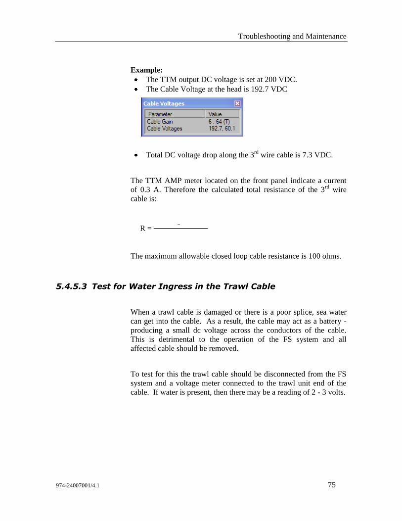
Troubleshooting and Maintenance
974-24007001/4.1 75
Example:
The TTM output DC voltage is set at 200 VDC.
The Cable Voltage at the head is 192.7 VDC
Total DC voltage drop along the 3rd
wire cable is 7.3 VDC.
The TTM AMP meter located on the front panel indicate a current
of 0.3 A. Therefore the calculated total resistance of the 3rd
wire
cable is:
R = –
The maximum allowable closed loop cable resistance is 100 ohms.
5.4.5.3 Test for Water Ingress in the Trawl Cable
When a trawl cable is damaged or there is a poor splice, sea water
can get into the cable. As a result, the cable may act as a battery -
producing a small dc voltage across the conductors of the cable.
This is detrimental to the operation of the FS system and all
affected cable should be removed.
To test for this the trawl cable should be disconnected from the FS
system and a voltage meter connected to the trawl unit end of the
cable. If water is present, then there may be a reading of 2 - 3 volts.
FS70 Trawl Sonar System
76 974-24007001/4.1
5.4.6 Telemetry Errors
In the normal operation of the FS Trawl Monitoring system
commands are sent from the processor unit down the trawl cable to
the trawl unit electronics and acknowledgments are then sent back
up to the processor unit. Some error checking of these commands is
performed to monitor the performance of the Uplink and Downlink
telemetry.
Telemetry errors can result from noise induced on the trawl cable
due to interference or problems with the 3rd
wire trawl cable or
trawl unit electronics.
Though a few telemetry errors are quite common and acceptable, an
excessive number of errors will adversely affect the sonar operation
and may indicate a problem that will eventually cause a system
failure.
The most common type of telemetry errors is time-outs. This
problem indicates the trawl unit electronics are not responding to
the processor unit or the integrated sensor module is not responding
to the sonar head.
If the processor unit displays changes in the “Baud Rate”
(highlighted in red and flashing) the change indicates that the
Uplink signal to the processor may have a problem then refer to the
“Message Log” file and record the “Errors” including the cable gain
number values and make note of any other failure.
If no errors are recorded in the “Message Log” file, then re-set the
baud rate to 115.2 kbps and implement a system re-calibration.
Next record the results obtained. The changes may have been
caused by noise or other interference.
5.4.7 Diagnostic Recordings
The system will save your screen displays in three different ways.
Two of these ways are manually started by the operator and the
third is automatically managed by the system. All three methods
create files on the system which can be sent to your service provider
for analysis.
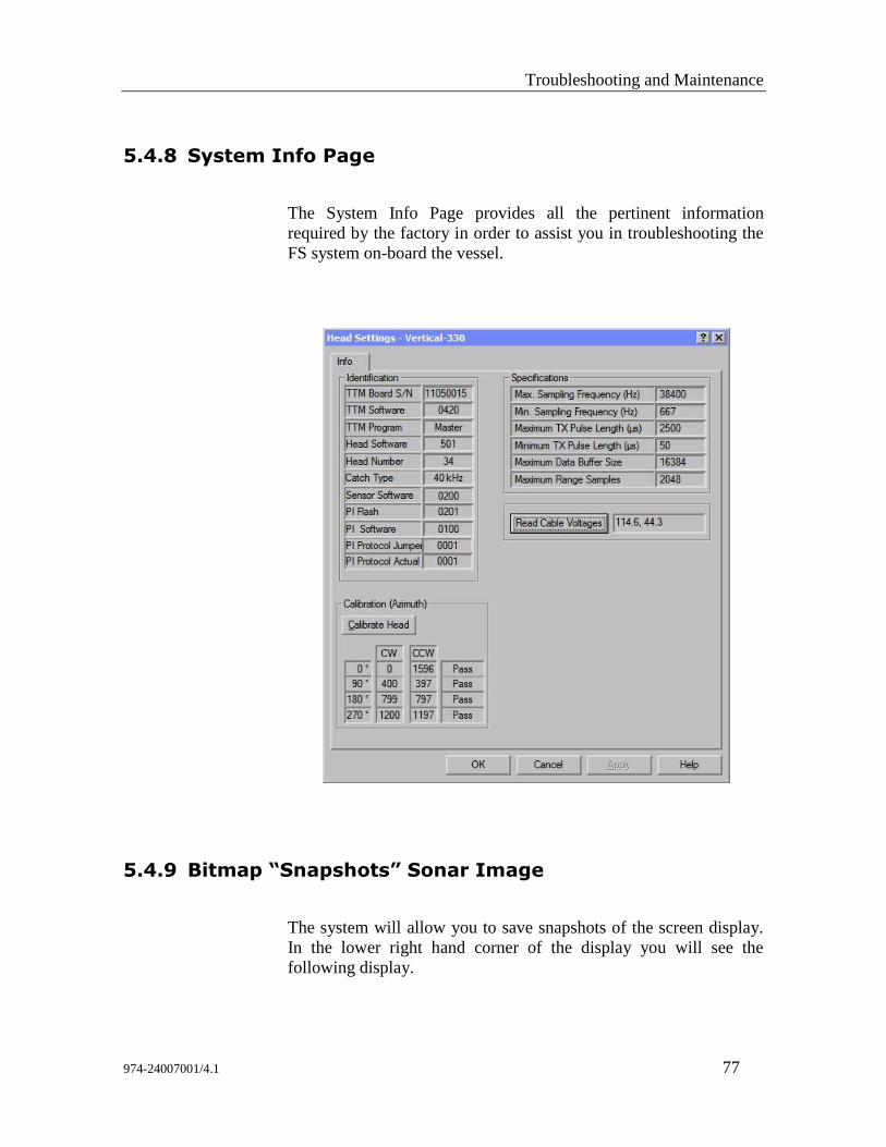
Troubleshooting and Maintenance
974-24007001/4.1 77
5.4.8 System Info Page
The System Info Page provides all the pertinent information
required by the factory in order to assist you in troubleshooting the
FS system on-board the vessel.
5.4.9 Bitmap “Snapshots” Sonar Image
The system will allow you to save snapshots of the screen display.
In the lower right hand corner of the display you will see the
following display.
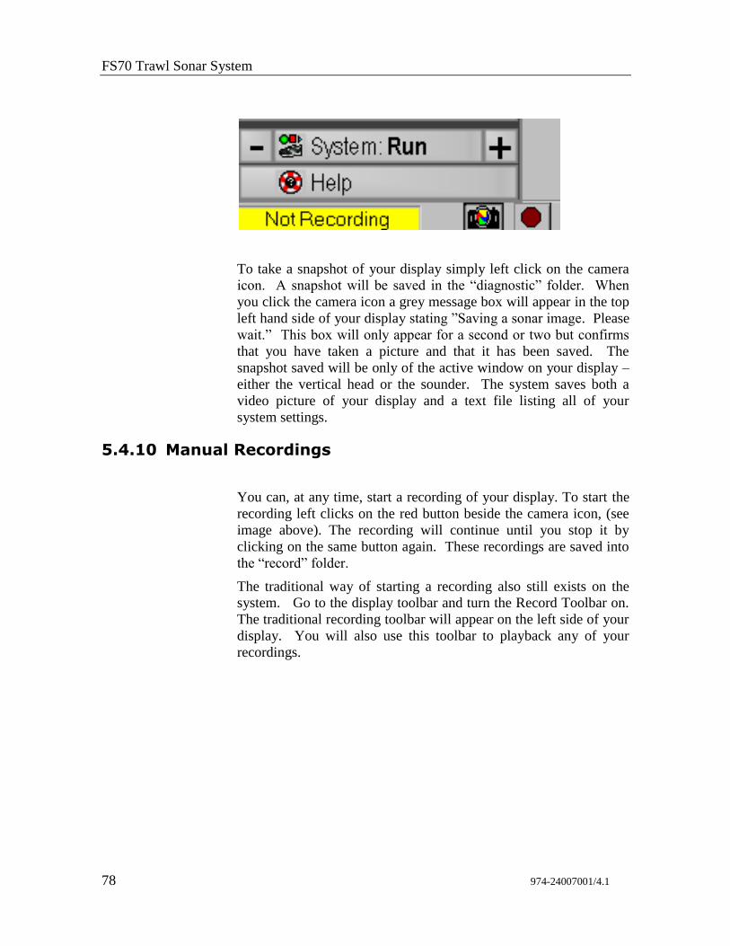
FS70 Trawl Sonar System
78 974-24007001/4.1
To take a snapshot of your display simply left click on the camera
icon. A snapshot will be saved in the “diagnostic” folder. When
you click the camera icon a grey message box will appear in the top
left hand side of your display stating ”Saving a sonar image. Please
wait.” This box will only appear for a second or two but confirms
that you have taken a picture and that it has been saved. The
snapshot saved will be only of the active window on your display –
either the vertical head or the sounder. The system saves both a
video picture of your display and a text file listing all of your
system settings.
5.4.10 Manual Recordings
You can, at any time, start a recording of your display. To start the
recording left clicks on the red button beside the camera icon, (see
image above). The recording will continue until you stop it by
clicking on the same button again. These recordings are saved into
the “record” folder.
The traditional way of starting a recording also still exists on the
system. Go to the display toolbar and turn the Record Toolbar on.
The traditional recording toolbar will appear on the left side of your
display. You will also use this toolbar to playback any of your
recordings.
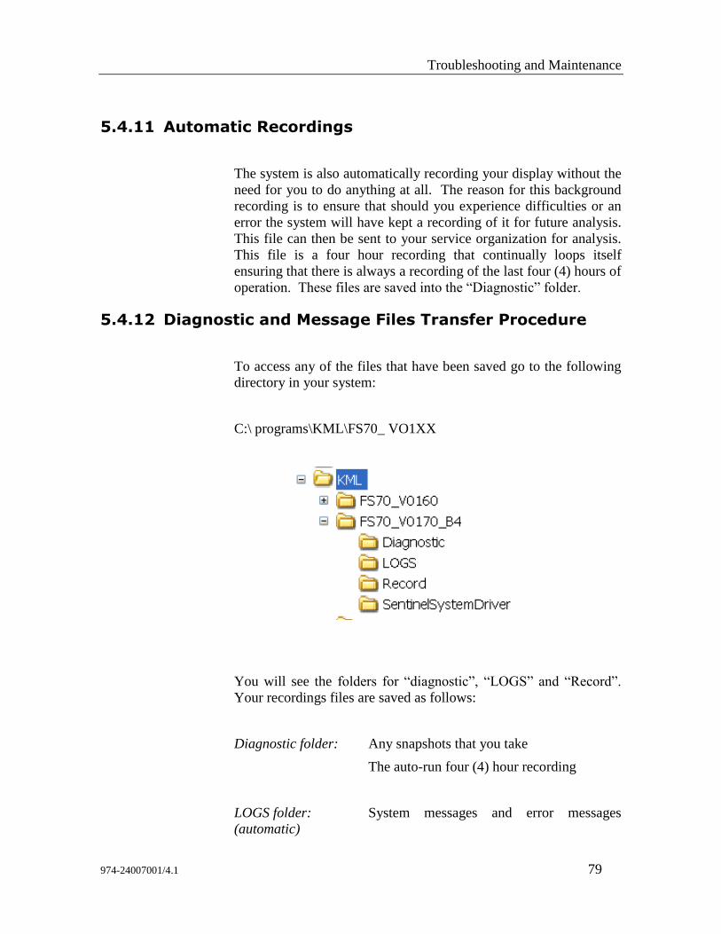
Troubleshooting and Maintenance
974-24007001/4.1 79
5.4.11 Automatic Recordings
The system is also automatically recording your display without the
need for you to do anything at all. The reason for this background
recording is to ensure that should you experience difficulties or an
error the system will have kept a recording of it for future analysis.
This file can then be sent to your service organization for analysis.
This file is a four hour recording that continually loops itself
ensuring that there is always a recording of the last four (4) hours of
operation. These files are saved into the “Diagnostic” folder.
5.4.12 Diagnostic and Message Files Transfer Procedure
To access any of the files that have been saved go to the following
directory in your system:
C:\ programs\KML\FS70_ VO1XX
You will see the folders for “diagnostic”, “LOGS” and “Record”.
Your recordings files are saved as follows:
Diagnostic folder: Any snapshots that you take
The auto-run four (4) hour recording
LOGS folder: System messages and error messages
(automatic)
FS70 Trawl Sonar System
80 974-24007001/4.1
Record folder: Any recordings that you manually start
All of these files are date and time stamped so you will know
exactly when they occurred.
If you have experienced a problem with the system you want to
ensure that the auto recording of the event will not be overwritten.
In this event you want to simply move the file from the “diagnostic”
folder and place it into a folder where you will easily be able to find
it. This file should be sent to your service provider at your earliest
convenience so that they can help determine what has caused the
problem.
5.4.13 Diagnosing Problems
The usefulness of these tools is greatly enhanced when they are
used on a regular basis to monitor system performance. Records of
past system performance (when the unit is operating properly)
provide a basis for comparison that may assist in diagnosing the
problem when an FS system fails.
If the FS system develops a problem, or if it fails completely, the
steps below should be followed.
1. Check the power supply unit meters and record their values. If the
failure was on power up, ensure the voltage selection switch is on
high and that the power is on. If the system developed a problem
or failed while operating, then note the voltage and current meter
behaviour. If the current meter jitters, then stop the trawl winch if
rotating, and note any changes in the meter values or their
behaviour.
2. If the processor unit displays a system test result page then record
the values and make note of any failure (highlighted in red). If not,
then implement a system test and record the results obtained.
3. Disconnect the trawl unit from the trawl cable and re-connect to the
FS system using the test cable, next re-power up the system. If the
system failed then you will have to troubleshoot the problem.
Troubleshooting and Maintenance
974-24007001/4.1 81
5.4.14 Troubleshooting Problems
The first step in troubleshooting the problem would be to retrieve
the “Errors” message log file located in the KLM directory as
indicated in paragraph 5.4.12. The errors log file will provide some
information of what when wrong with the system.
The next step is to understand the “Power up Sequence of Events”
when you power up the FS system. By understanding the system
sequence of events it will help you in diagnosing where the problem
may be.
5.4.15 Power up Sequence of Events
What happens when you turn “ON” the Power/TTM?
1. When you turn ON the TTM you apply power to the Pre-
Regulator board located in the sonar head.
2. Next, the pre-regulator board applies power to the main power
supply.
3. Next, the main power supply board sets-up the voltages
required to run the sonar head.
4. Next the motor will lock up in position “will not rotate freely by
hand”.
If the Pre-regulator and Power supply boards are functioning
correctly, the TTM panel meter should indicate 200Vdc and a
current of approx 0.20 Amp.
Troubleshooting system power problems:
Check TTM Interface unit panel meters for voltage and
current, ensure unit is on and confirm voltage meter
indicates 200 VDC.
If no current is indicated then turn power off and disconnect
the third wire cable from the TTM Unit. Check wiring
continuity between the MS connector and the 2 pin
connector at the trawl unit. If OK, then the sonar head needs
servicing.
FS70 Trawl Sonar System
82 974-24007001/4.1
5.4.16 Host FS70 Software Start-up Sequence of Events
In this section we will be addressing the telemetry communication
and highlighting the action/problems and the possible causes.
What happens when you start up the host software?
When you start up the FS host software you are establishing
“Digital” communication with the TTM boards located inside the
Power/TTM unit.
The communication is establish between the PC and the TTM using
the host software commend by clicking on “Detect Head” if the host
do not detect the “Head” you will have to troubleshoot where the
problem may be as indicated below.
Troubleshooting head detection problems:
Check COM port is activated in host software. If not, then
activate the COM port and re-detect head.
If head not detected, then check connection between the PC
and TTM. If OK, the TTM needs servicing.
After the host has detected the “digital side” of the TTM board, the
“Analog” side of the TTM board and via the LF1 telemetry board
unit completes the downlink communication through the LF1
telemetry board located in the sonar head.
5.4.17 What happens when you click “RUN”
The next steps after the host software is detected and you hit the
“Run” button are:
Cable Calibration
The CPU board will request a series of transmit pulses from the
transmitter to initiate the cable calibration. While this is occurring
the surface unit (via the TTM/LF1 board) will increase/decrease the
values (returned signal “echo’s”) via the receiver board and will be
uplinked and written to the Digital-to-Analog Converter “DAC”
such that the Gain-Detect (monitor by the TTM) is first detected
then intentionally turned off and then detected again by changing
Troubleshooting and Maintenance
974-24007001/4.1 83
the values being uplinked and re-written back to the DACs. The
final values written to the DACs directly represent what we refer to
as the “Cable Gain Numbers” i.e., example “6, 23” to compensate
for the signal loss through the 3rd wire.
The most important steps regarding the Downlink and Uplink
communication between the host software, the TTM and the sonar
head is completed. If any problems were detected with the TTM/
LF1 telemetry, the LF1 telemetry board in the sonar head, the CPU
board, the transmitter or the receiver boards the cable calibration
would have failed.
Motor Calibration
After the downloading of the head parameters is completed the host
software via the CPU board will request a motor calibration. The
motor driver board will come online and calibrate the motor with a
series of rotations in order to detect the optocouplers located in the
motor housing and set-up each quadrant. The 4 quadrants and
calibration numbers will be recorded in the host software “info”
page.
If the motor calibration fails the problem may be with the motor
controller board of the optocouplers located in the motor housing.
Sensors Info Request
The next step the host must know what is connected to the system
in respect to the type of sensors. A command requesting is
downlinked to the head CPU board, the CPU will request the info
from the sensors controller board, e.g., Catch sensors, temp and
depth, Door Spread sensors etc. After the controller board has
completed the detection the info is uplinked back to the host
software via the CPU, LF1 telemetry board in the sonar head, then
uplinked to the TTM via the LF1 telemetry board.
After the Host has received the information then the sensors page
including the data will be displayed on the sonar image.
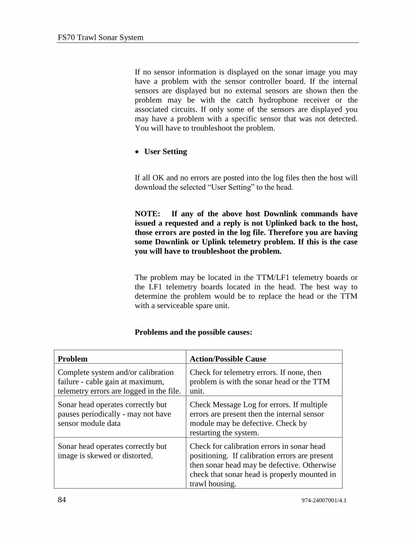
FS70 Trawl Sonar System
84 974-24007001/4.1
If no sensor information is displayed on the sonar image you may
have a problem with the sensor controller board. If the internal
sensors are displayed but no external sensors are shown then the
problem may be with the catch hydrophone receiver or the
associated circuits. If only some of the sensors are displayed you
may have a problem with a specific sensor that was not detected.
You will have to troubleshoot the problem.
User Setting
If all OK and no errors are posted into the log files then the host will
download the selected “User Setting” to the head.
NOTE: If any of the above host Downlink commands have
issued a requested and a reply is not Uplinked back to the host,
those errors are posted in the log file. Therefore you are having
some Downlink or Uplink telemetry problem. If this is the case
you will have to troubleshoot the problem.
The problem may be located in the TTM/LF1 telemetry boards or
the LF1 telemetry boards located in the head. The best way to
determine the problem would be to replace the head or the TTM
with a serviceable spare unit.
Problems and the possible causes:
Problem Action/Possible Cause
Complete system and/or calibration
failure - cable gain at maximum,
telemetry errors are logged in the file.
Check for telemetry errors. If none, then
problem is with the sonar head or the TTM
unit.
Sonar head operates correctly but
pauses periodically - may not have
sensor module data
Check Message Log for errors. If multiple
errors are present then the internal sensor
module may be defective. Check by
restarting the system.
Sonar head operates correctly but
image is skewed or distorted.
Check for calibration errors in sonar head
positioning. If calibration errors are present
then sonar head may be defective. Otherwise
check that sonar head is properly mounted in
trawl housing.
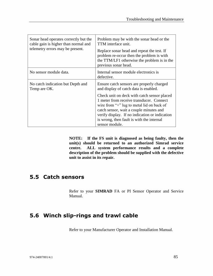
Troubleshooting and Maintenance
974-24007001/4.1 85
Sonar head operates correctly but the
cable gain is higher than normal and
telemetry errors may be present.
Problem may be with the sonar head or the
TTM interface unit.
Replace sonar head and repeat the test. If
problem re-occur then the problem is with
the TTM/LF1 otherwise the problem is in the
previous sonar head.
No sensor module data. Internal sensor module electronics is
defective.
No catch indication but Depth and
Temp are OK.
Ensure catch sensors are properly charged
and display of catch data is enabled.
Check unit on deck with catch sensor placed
1 meter from receive transducer. Connect
wire from “+” lug to metal lid on back of
catch sensor, wait a couple minutes and
verify display. If no indication or indication
is wrong, then fault is with the internal
sensor module.
NOTE: If the FS unit is diagnosed as being faulty, then the
unit(s) should be returned to an authorized Simrad service
centre. ALL system performance results and a complete
description of the problem should be supplied with the defective
unit to assist in its repair.
5.5 Catch sensors
Refer to your SIMRAD FA or PI Sensor Operator and Service
Manual.
5.6 Winch slip-rings and trawl cable
Refer to your Manufacturer Operator and Installation Manual.
FS70 Trawl Sonar System
86 974-24007001/4.1
6 DRAWINGS
Drawings List
436-00411000 - Test Cable
901-60181001 - FS power/TTM Outline Dwg
901-60181003 - FS Power/TTM Wiring Diagram
974-80161000 - FS 70 Housing Dwg (4 Dwgs)
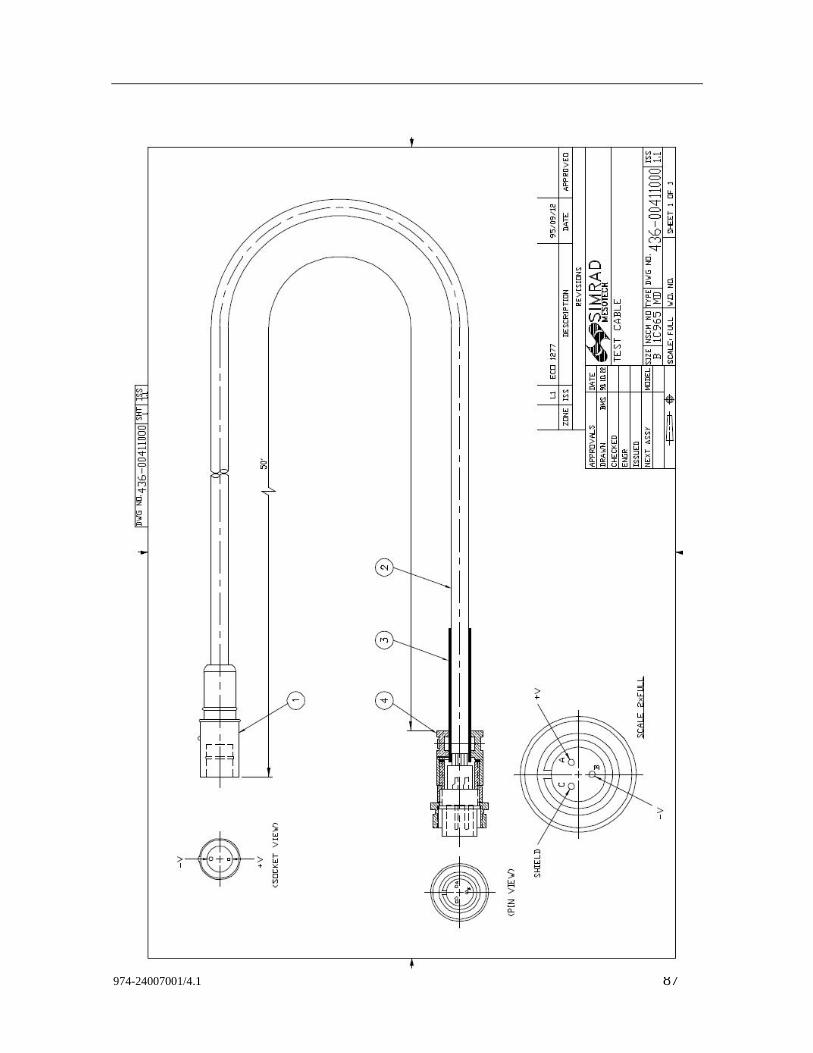
974-24007001/4.1 87
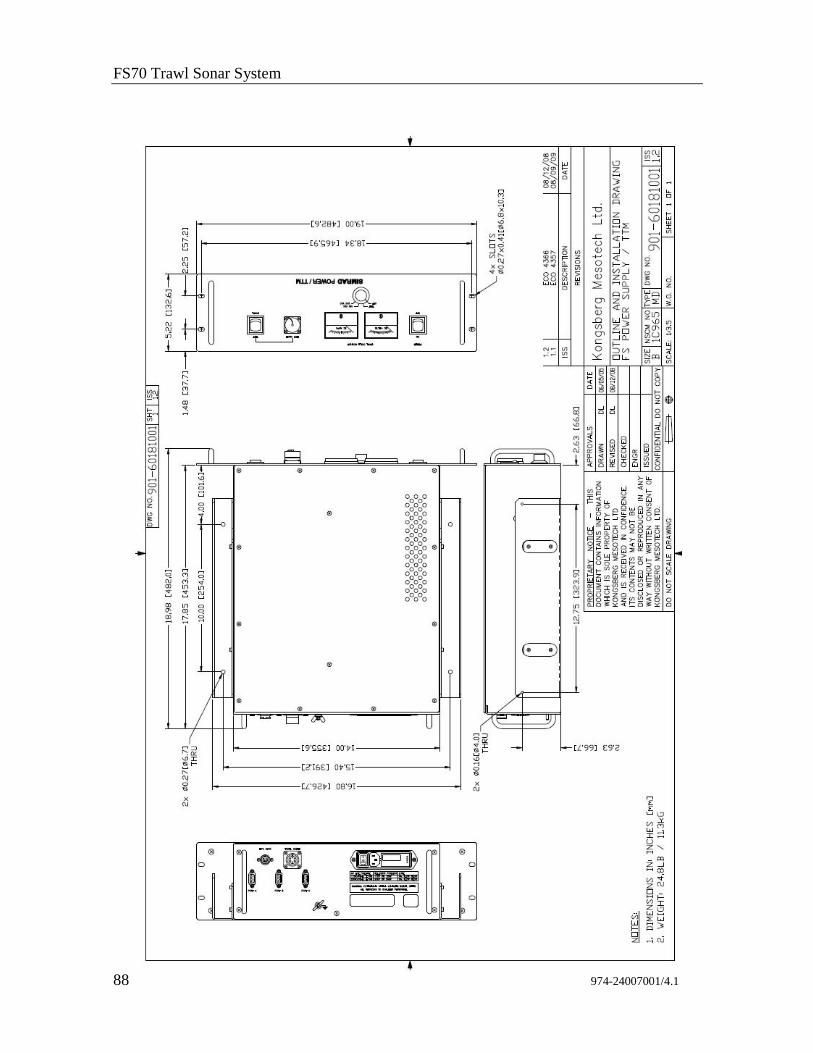
FS70 Trawl Sonar System
88 974-24007001/4.1
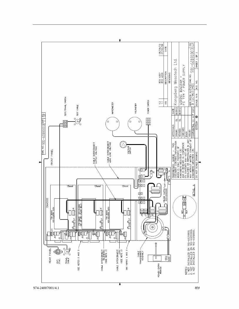
974-24007001/4.1 89
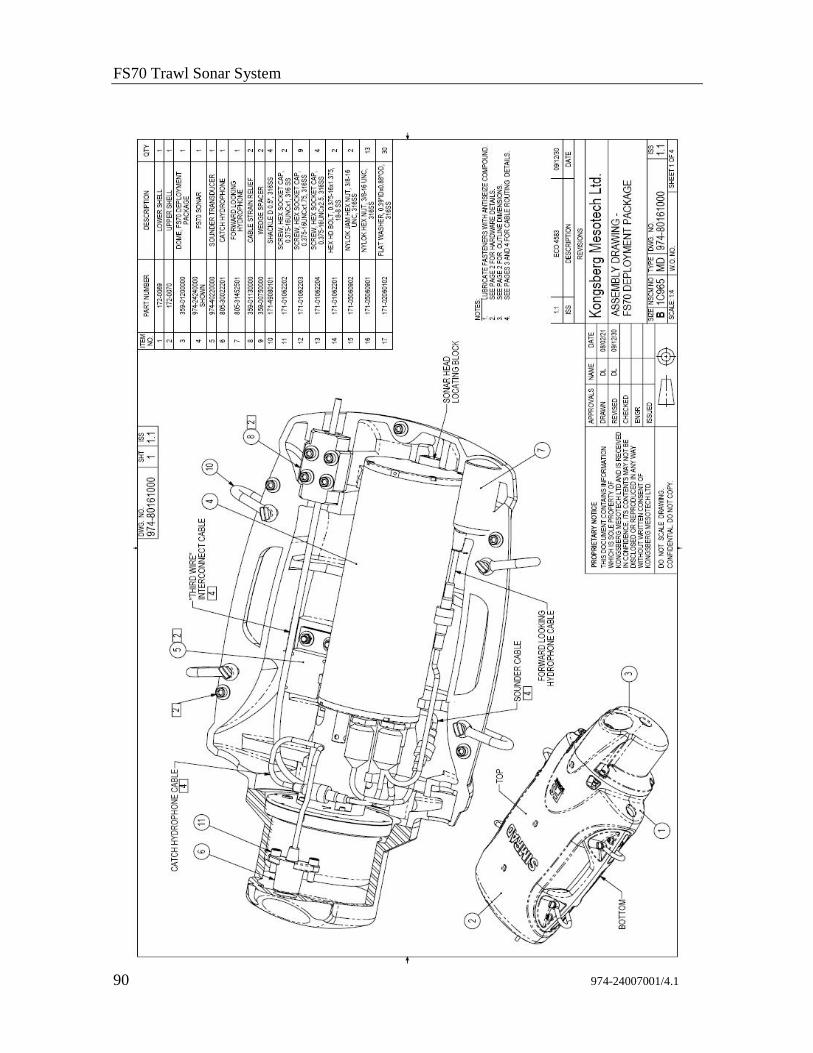
FS70 Trawl Sonar System
90 974-24007001/4.1
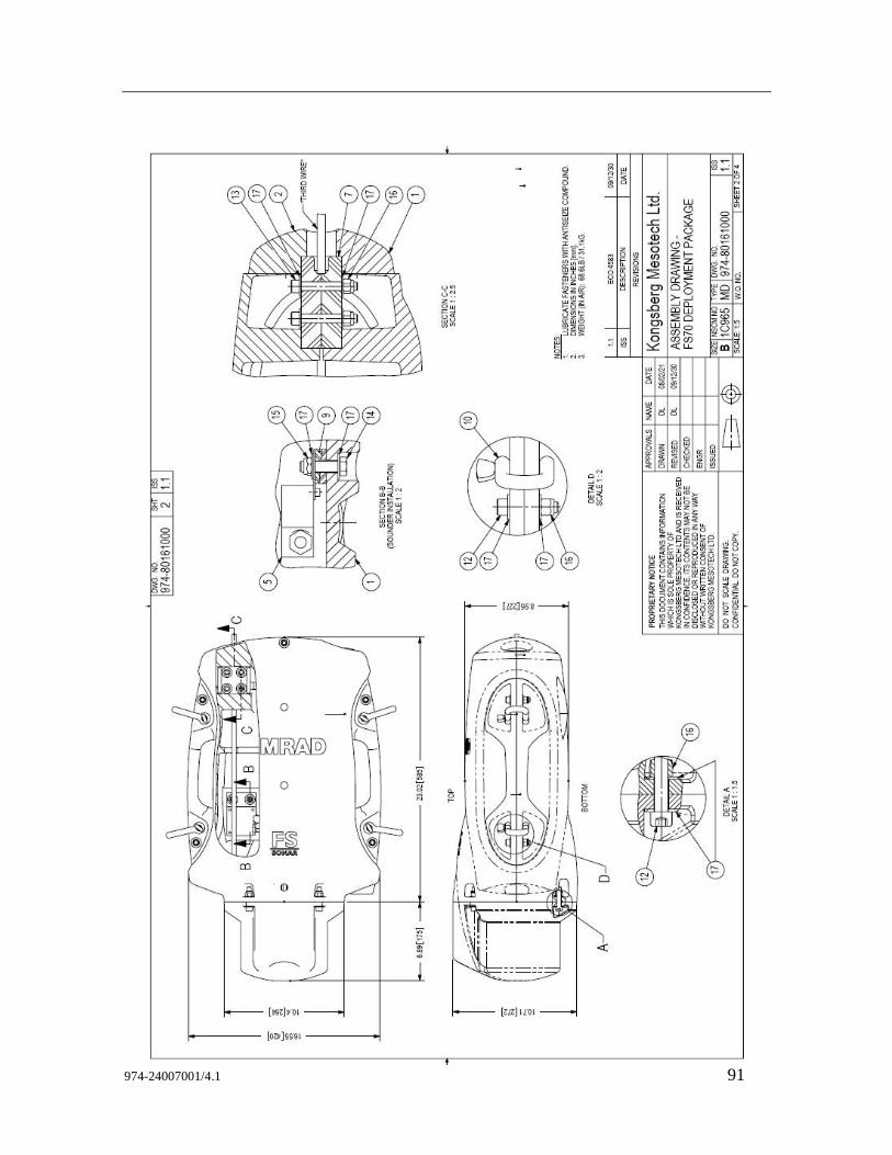
974-24007001/4.1 91
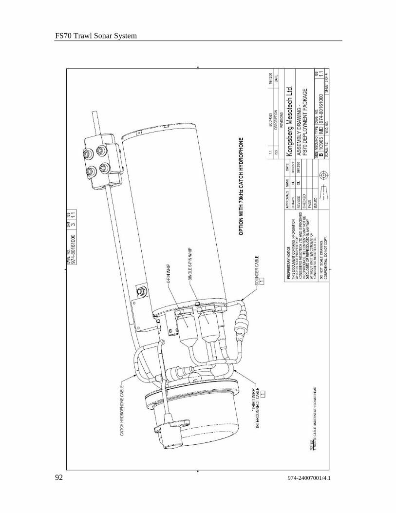
FS70 Trawl Sonar System
92 974-24007001/4.1
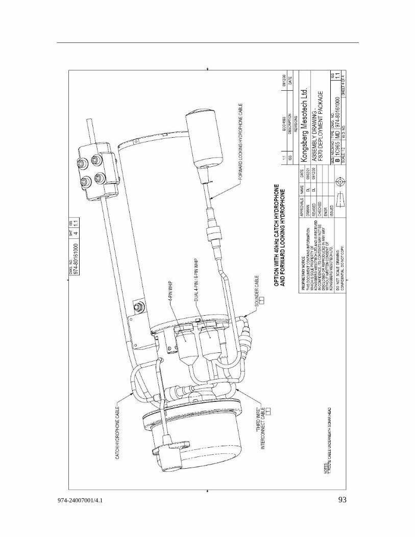
974-24007001/4.1 93

FS70 Trawl Sonar System
94 974-24007001/4.1
<This page is left intentionally blank>
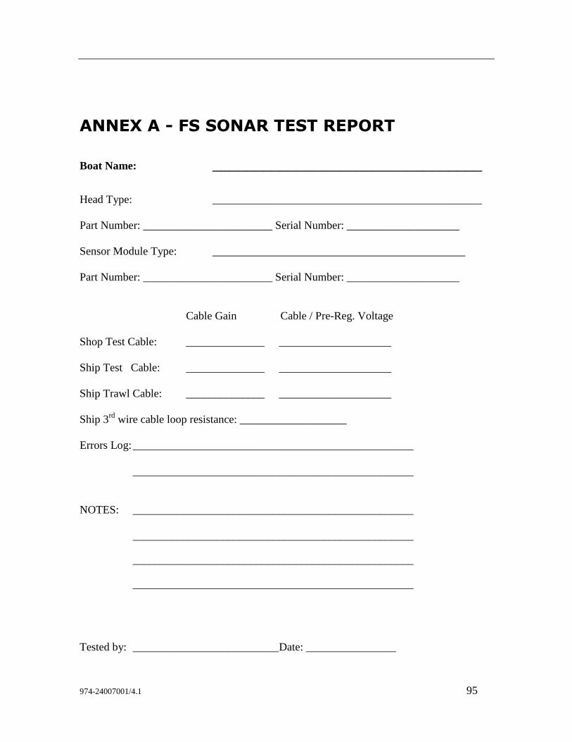
974-24007001/4.1 95
ANNEX A - FS SONAR TEST REPORT
Boat Name: ________________________________
Head Type: ________________________________________________
Part Number: _______________________ Serial Number: ____________________
Sensor Module Type: _____________________________________________
Part Number: _______________________ Serial Number: ____________________
Cable Gain Cable / Pre-Reg. Voltage
Shop Test Cable: ______________ ____________________
Ship Test Cable: ______________ ____________________
Ship Trawl Cable: ______________ ____________________
Ship 3rd
wire cable loop resistance: ___________________
Errors Log: __________________________________________________
__________________________________________________
NOTES: __________________________________________________
__________________________________________________
__________________________________________________
__________________________________________________
Tested by: __________________________ Date: ________________

FS70 Trawl Sonar System
96 974-24007001/4.1
<This page is left intentionally blank>
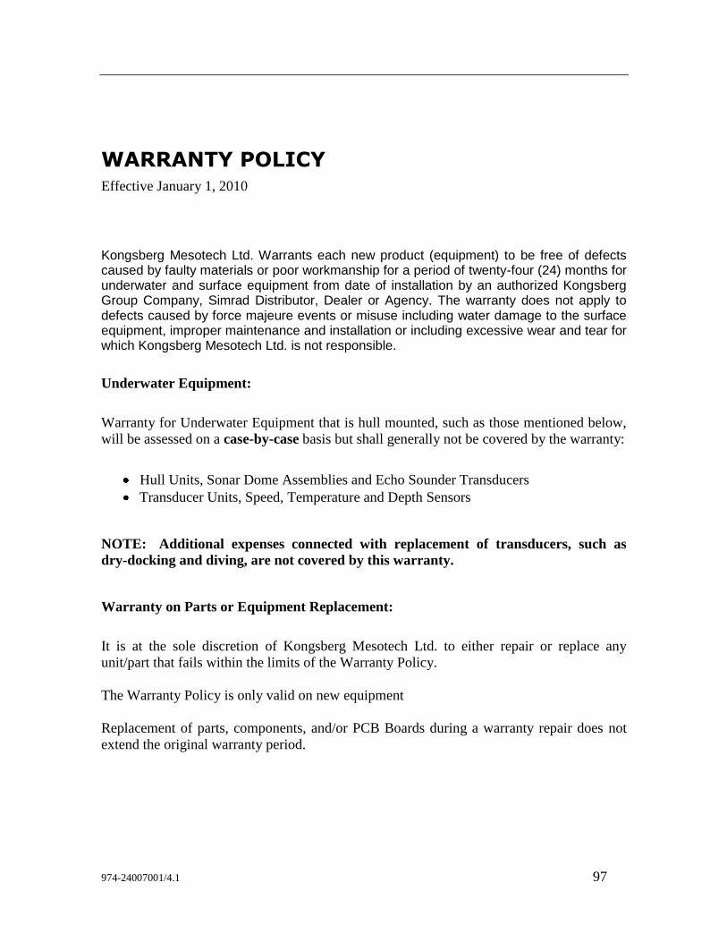
974-24007001/4.1 97
WARRANTY POLICY
Effective January 1, 2010
Kongsberg Mesotech Ltd. Warrants each new product (equipment) to be free of defects caused by faulty materials or poor workmanship for a period of twenty-four (24) months for underwater and surface equipment from date of installation by an authorized Kongsberg Group Company, Simrad Distributor, Dealer or Agency. The warranty does not apply to defects caused by force majeure events or misuse including water damage to the surface equipment, improper maintenance and installation or including excessive wear and tear for which Kongsberg Mesotech Ltd. is not responsible.
Underwater Equipment:
Warranty for Underwater Equipment that is hull mounted, such as those mentioned below,
will be assessed on a case-by-case basis but shall generally not be covered by the warranty:
Hull Units, Sonar Dome Assemblies and Echo Sounder Transducers
Transducer Units, Speed, Temperature and Depth Sensors
NOTE: Additional expenses connected with replacement of transducers, such as
dry-docking and diving, are not covered by this warranty.
Warranty on Parts or Equipment Replacement:
It is at the sole discretion of Kongsberg Mesotech Ltd. to either repair or replace any
unit/part that fails within the limits of the Warranty Policy.
The Warranty Policy is only valid on new equipment
Replacement of parts, components, and/or PCB Boards during a warranty repair does not
extend the original warranty period.
FS70 Trawl Sonar System
98 974-24007001/4.1
Consumable Materials:
Consumable materials, such as lamps, fuses, O-rings, gaskets and batteries, will not be
replaced free of charge.
Warranty Service:
Warranty service is available worldwide through authorized Kongsberg Group Companies,
Simrad Distributors, Dealers or Agencies. When requesting warranty service, you must
supply the following information:
1. Proof of purchase.
2. Equipment part number and serial number.
3. Fault description and all relevant vessel information.
Labour cost for the repair or replacement of any products/equipment and/or module/parts is
the responsibility of the servicing agent or dealer.
All customs duties, brokerage charges local taxes, overtime, expenses for meals, tools,
launch services, ferries, lodgings, normal adjustments and routine maintenance are not
covered by this warranty policy.
DISCLAIMER
Maximum liability shall not, in any case, exceed the contract price of the products claimed
to be defective.
Consequential damages including, but not limited to, any loss of profit, property damage or
personal injury, are not covered by the warranty policy.
This equipment is not certified or approved for navigation and/or safe-navigation practices,
and is not to be used for navigation purposes under any circumstances.

<This page is left intentionally blank>

2010 Kongsberg Mesotech
SIMRAD