Embed Size (px)
Citation preview
Knowledge-based control of vision systems
C. Shekhara,* , S. Moisanb, R. Vincentc, P. Burlinaa, R. Chellappaa
aCenter for Automation Research, University of Maryland, College Park, MD 20742, USAbINRIA Sophia-Antipolis, 2004 Route des Lucioles, Sophia-Antipolis Cedex, France
cDepartment of Computer Science, University of Massachusetts, Amherst, MA 01003-4610, USA
Received 16 September 1997; received in revised form 10 April 1998; accepted 22 April 1998
Abstract
We propose a framework for the development of vision systems that incorporate, along with the executable computer algorithms, theproblem-solving knowledge required to obtain optimal performance from them. In this approach, the user provides the input data, specifiesthe vision task to be performed, and then provides feedback in the form of qualitative evaluations of the results obtained. These assessmentsare interpreted in a knowledge-based framework to automatically select algorithms and set parameters until results of the desired quality areobtained. This approach is illustrated on two real applications, and examples from the knowledge bases developed are discussed in detail.q 1999 Elsevier Science B.V. All rights reserved.
Keywords:Vision system; Knowledge-based control; Self-tuning; Algorithm selection; Parameter tuning
1. Introduction
Vision systems used in challenging operational environ-ments should satisfy the conflicting requirements of flex-ibility and convenience. Flexibility is the ability toaccommodate variations in operating conditions. Conveni-ence pertains to the ease of operation of the system by a userwho is not familiar with the technical details of the algo-rithms employed.
Variations in image characteristics are caused by anumber of factors such as weather, lighting conditions andimage acquisition parameters. A vision system shouldaccommodate a reasonable amount of such variation, andshould degrade gracefully as the image characteristics deviatefrom the ideal. One can allow for such variations by providingalternative algorithms for each task, as well as tuning para-meters for each algorithm. In most cases, a judicious choice ofalgorithms and parameters provides results of acceptablequality under a wide range of operating conditions.
Vision systems in the real world are often utilized byusers who, while competent in the visual analysis of images,may not be familiar with the technical details of the algo-rithms they employ. It is not reasonable to expect the userfunctioning in an operational situation to select and tune thealgorithms for the task (s)he is required to perform. Thisfunction is best left to the designer, the vision specialist,
who may not be available during the system’s operation.It is thus obvious that a vision system that providesflexibil-ity in the choice of algorithms and parameter values may notbe veryconvenientfor the user to utilize.
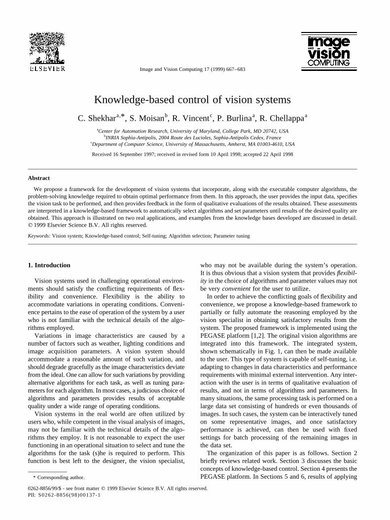
In order to achieve the conflicting goals of flexibility andconvenience, we propose a knowledge-based framework topartially or fully automate the reasoning employed by thevision specialist in obtaining satisfactory results from thesystem. The proposed framework is implemented using thePEGASE platform [1,2]. The original vision algorithms areintegrated into this framework. The integrated system,shown schematically in Fig. 1, can then be made availableto the user. This type of system is capable of self-tuning, i.e.adapting to changes in data characteristics and performancerequirements with minimal external intervention. Any inter-action with the user is in terms of qualitative evaluation ofresults, and not in terms of algorithms and parameters. Inmany situations, the same processing task is performed on alarge data set consisting of hundreds or even thousands ofimages. In such cases, the system can be interactively tunedon some representative images, and once satisfactoryperformance is achieved, can then be used with fixedsettings for batch processing of the remaining images inthe data set.
The organization of this paper is as follows. Section 2briefly reviews related work. Section 3 discusses the basicconcepts of knowledge-based control. Section 4 presents thePEGASE platform. In Sections 5 and 6, results of applying
Image and Vision Computing 17 (1999) 667–683
0262-8856/99/$ - see front matterq 1999 Elsevier Science B.V. All rights reserved.PII: S0262-8856(98)00137-1
* Corresponding author.
our methodology to two candidate applications (syntheticaperture radar (SAR) image analysis and vehicle detectionin aerial imagery) are presented. These applications, devel-oped at the University of Maryland, were selected firstlybecause they address interesting and non-trivial problems,and secondly because their developers were available toprovide the required expertise, indispensable for construct-ing the knowledge bases. The final section contains theconclusions resulting from our work, as well as a list ofareas for further investigation.
2. Previous work
As vision algorithms and systems have grown in powerand complexity during the past few decades, there has beena corresponding growth in software platforms tailored tovision system development. Traditional methods rangefrom graphical script generators, to vision toolkits, toobject-oriented protocols for data and program interchange.The emphasis is on abstracting the types of objects andcomputational geometries used in image understandinginto useful programming constructs [3]. One of the objec-tives is to enable the rapid design of algorithms using a tool-box of pre-existing constructs, and prototyping of longerprocessing chains by linking simpler elements together.The user is often provided with a visual programming envir-onment (VPE), which enables him or her to mix-and-matchbetween the available methods. For the most part, thesesystems offer onlysyntactic integrationof vision algo-rithms. They provide a means to integrate code and usagesyntaxes, but do not provide a means to incorporate furtherknowledge about the algorithms.
Knowledge-based techniques can be used in various ways
in the development of vision systems. For an excellentsurvey of this topic, see Ref. [4]. Knowledge-based systems,also known as expert systems, have been traditionally usedfor the high-level interpretation of images, and for specificvision tasks such as segmentation (e.g. Ref. [5]). Theyincorporate mechanisms for the spatial and temporal reason-ing that is characteristic of intermediate- and high-levelimage understanding. These knowledge-based systems aretailored towards specific tasks, and are usually not general-izable to other tasks. The work presented in this paper isdifferent in that it proposes a general-purpose framework forknowledge-based control of vision systems. The approachcan be used to develop knowledge-based autonomous orsemi-autonomous systems for any vision application. Thispaper builds on work previously reported in Refs. [6,7].
Some of the early work with a similar motivation isreported in Refs. [8–12]. More recently, this problem hasbeen addressed in the context of the VIDIMUS project [13],with the aim of developing an intelligent vision environ-ment for industrial inspection. A knowledge-based system(VSDE) was built within this environment, which can auto-matically configure a vision system for a given inspectionproblem. The automatic generation of an image-processingscript based on a user request and a knowledge-based modelof an application domain is addressed in Ref. [14]. In Ref.[15] vision algorithm control is modeled as a Markov deci-sion problem. This model is used to automatically assembleobject recognition algorithms from existing vision modules.In Refs. [16,17] a context-based vision paradigm isproposed, where the basic aim is to use contextual informa-tion to select methods and parameters in a vision applica-tion. The authors emphasize the need for explicitly encodingsemantic knowledge about vision algorithms such asassumptions about their use and their inherent limitations.
C. Shekhar et al. / Image and Vision Computing 17 (1999) 667–683668
Fig. 1. Architecture of a self-tuning vision system. The vision system has a number of stages of processing, with different possible algorithm choices at eachstep. Each algorithm may have one or more tunable parameters. The user evaluates the result(s) of processing, and the control module uses this feedback tochange algorithms or parameters in order to improve the results.
The work reported in Ref. [18] is very close in spirit to theapproach presented in this paper. The authors’ motivation isto make it easier for non-specialists to use the SPIDER [11]image-processing library. They propose a three-layeredknowledge-based system: the first layer contains generalknowledge about problem-solving and the use of softwarepackages, the second contains knowledge about imageprocessing and the third contains knowledge about theSPIDER library. The problem-solving strategy consists ofproblem classification, division of the problem into sub-problems, selection of appropriate methods and invocationof the appropriate SPIDER routines. Routines are automa-tically parameterized and executed. Intermediate results areevaluated to decide whether alternative ways of processingare preferable. They provide a backtrack mechanism tohandle failures. The main limitation of their method istheir reliance on the characteristics of the SPIDER library,which has been designed in a specific fashion, using princ-iples of modularity, homogeneity and software re-use.Unlike the approach presented here, their method is noteasily extensible to other algorithm libraries. Anotherlimitation is their use of Prolog to represent all types ofknowledge, whereas certain types of knowledge, such asthe structure of algorithms, are better represented usingframes.
3. Knowledge-based control
In a typical vision application, a number of stages ofprocessing are involved in going from the raw input data
to the final result, as shown in Fig. 1. Typically, at eachstage of processing a number of alternative algorithms canbe employed. Each of these algorithms, in turn, may haveone or more tunable parameters. These parameters may becontinuously variable, or may take discrete sets of values.Often, due to uncertainty in the data and in the problemmodel, it is not possible to predict beforehand if a givenalgorithm sequence will produce the desired result for acertain parameter setting. It may be necessary to start witha rough guess of the parameter values, execute the algorithmsequence, examine the results and, if necessary, modify theparameter values or the selection of algorithms, and repeatthe procedure until results of the desired quality areobtained.
In this section, we examine the types of knowledge usedby a vision specialist (and therefore required for knowledge-based control), and the implications for the design of self-tuning vision systems.
3.1. Smart modules
From a problem-solving perspective, the task of solving avision problem using a given set of algorithms involvesthree types of knowledge: syntax, semantics and strategy.Syntactic knowledge is information about input and outputdata types and formats, input parameters, command-linearguments, etc. Information such as memory required mayalso be considered as syntactic knowledge. Semantic knowl-edge is the vision specialist’s expertise about the character-istics of the algorithms, result evaluation, assembly ofalgorithms for a given task, etc. Strategic knowledgepertains to the high-level decisions that should be madeabout result evaluation (by the system, by the user, or notat all) and failure handling (repair failure at the currentmodule or at another place in the chain of processing, repairfailure by parameter tuning or by algorithm reselection,etc.).
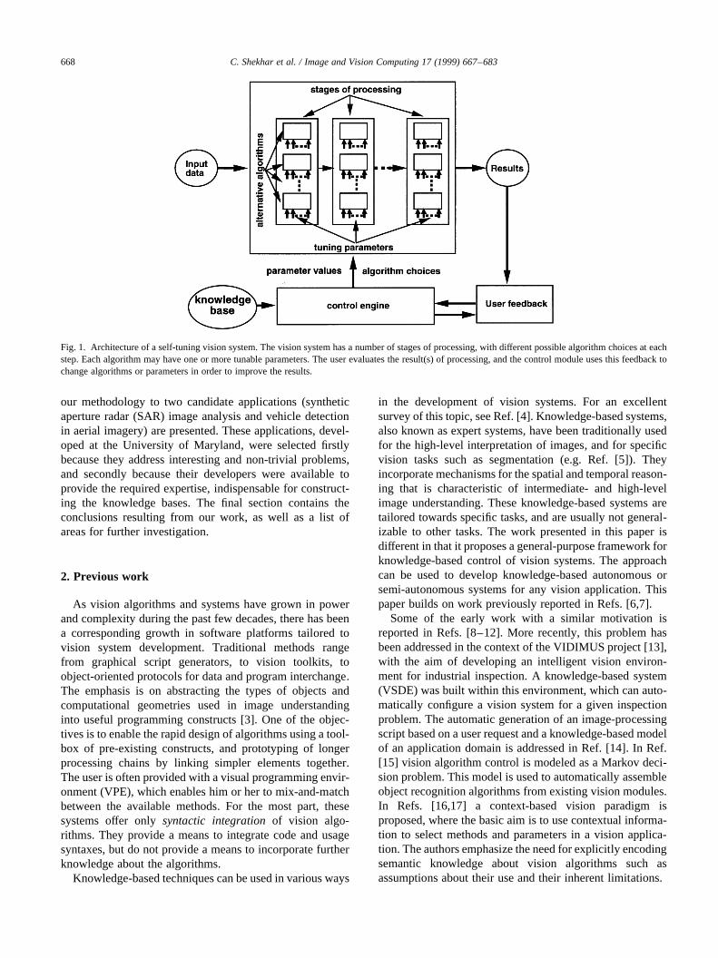
The objective of knowledge-based control is to provide asuitable framework for ‘packaging’ algorithms using thethree types of knowledge described above. Conceptually,as shown in Fig. 2, raw algorithms are wrapped with layersof syntactic, semantic and strategic knowledge to form‘smart’ modules. This can be done in a recursive fashionfor more complex tasks—smart modules can be connectedsequentially, or in parallel, or selectively, and the ensemblecan then be re-wrapped.
3.2. Self-tuning
Self-tuning is the ability of the vision system to select theappropriate algorithms and parameter values based on theinput data, contextual information, and feedback from theuser in the form of result evaluations. In many cases, algo-rithms can be selected based on contextual informationalone [16], before any data processing has taken place. Para-meter tuning, on the other hand, is dependent on the char-acteristics of the specific data set. It has to be interleaved
C. Shekhar et al. / Image and Vision Computing 17 (1999) 667–683 669
Fig. 2. Packaging a vision algorithm into a ‘smart’ module. A ‘raw’ algo-rithm (in the form of an executable computer program) is not useful toanyone except the specialist who designed and implemented it. In orderfor another person, particularly a non-specialist, to use the algorithm, itmust be accompanied by some knowledge about how to run it, how toevaluate its results, how to tune it, etc. Smart modules can themselves beconnected in various ways and re-packaged for more complex tasks.
with the processing of the data, based on the operator’sevaluation of the results. In the cases where no satisfactoryresult is obtained even after tuning the parameters, one ormore algorithms may have to be replaced by more suitableones.
Consider a vision systemA composed ofmstages, withni
parameters in theith stage:
A� A1A2…Ai…Am
where eachAi is of the form
Ai � Ai�pi1;pi2;…pini�
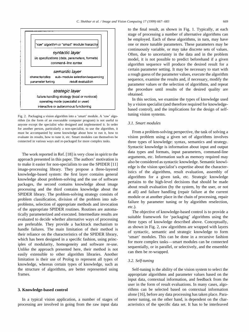
As shown in Fig. 3 the entire vision system can be regardedas consisting of a single algorithmA(p1,p2,…,pN). The Nparameters that tune this ‘black box’ algorithm are theSi�1
m ni parameters of them individual stages. We refer toa specific setting of theseN parameters as an operating point(OP). We define an acceptable operating point as a para-meter setting that yields satisfactory performance for thegiven data set. Our basic assumption is that there exists atleast one acceptable operating point (or, more generally, toaccount for continuous-valued parameters, operatingregion). In general, the default parameter setting will notbe an acceptable one. The objective, then, is to be able tofind an acceptable OP for the given data set in an efficientmanner. In the case of discrete parameters, if each parameter
pi has ki possible values, the total number of parametersettings isP iki. An exhaustive search of theN-dimensionalparameter space may therefore be too computationallyexpensive. The situation is even worse with continuouslyvalued parameters, since there are an infinite number ofpotential parameter settings. Further, it is bound to be tire-some for the user who has to evaluate the results at each stepand provide feedback. This is where it is advantageous touse a knowledge-based approach. A vision specialistemploys a problem-solving technique consisting of heuris-tics, rules of thumb, etc., which effectively help him or herfind a short cut (‘tuning path’) to an acceptable operatingpoint, without having to explore the entire parameter space.If there are multiple operating regions we need to be able tofind a tuning path to an acceptable operating point lying inany one of them. Using a knowledge-based approach, thetechnique employed by the specialist can be integrated intothe vision system to give it a self-tuning capability.
3.3. Modes of operation
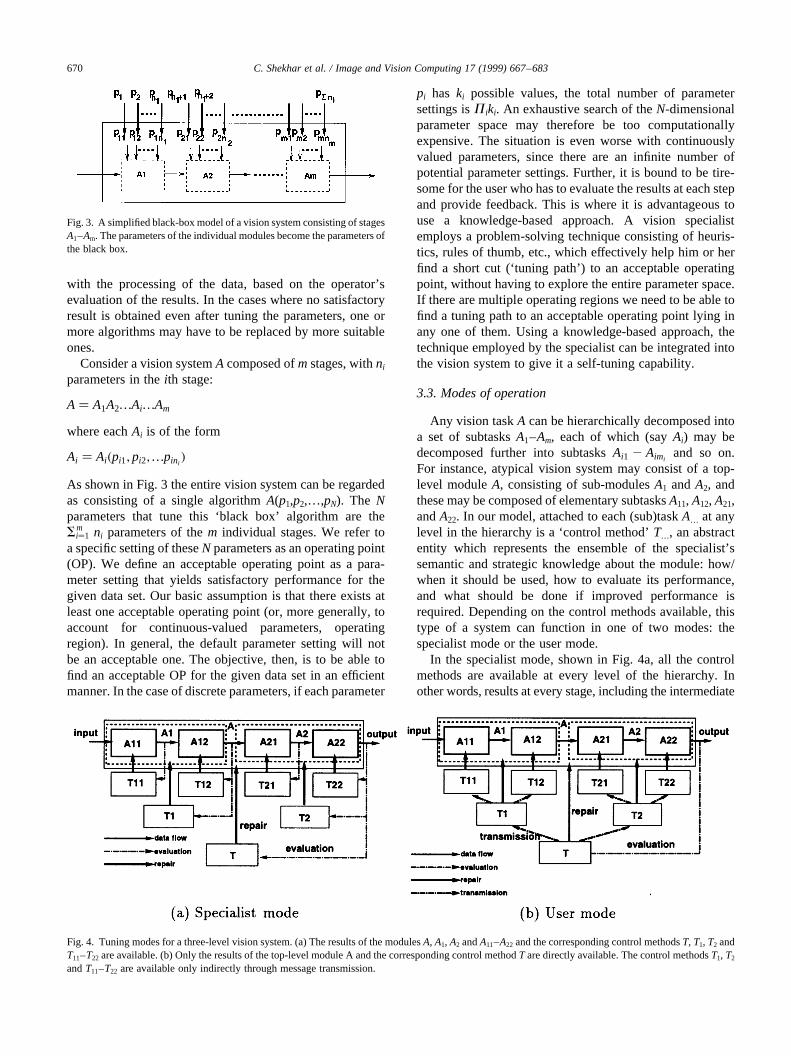
Any vision taskA can be hierarchically decomposed intoa set of subtasksA1–Am, each of which (sayAi) may bedecomposed further into subtasksAi1 2 Aimi
and so on.For instance, atypical vision system may consist of a top-level moduleA, consisting of sub-modulesA1 andA2, andthese may be composed of elementary subtasksA11, A12, A21,andA22. In our model, attached to each (sub)taskA… at anylevel in the hierarchy is a ‘control method’T…, an abstractentity which represents the ensemble of the specialist’ssemantic and strategic knowledge about the module: how/when it should be used, how to evaluate its performance,and what should be done if improved performance isrequired. Depending on the control methods available, thistype of a system can function in one of two modes: thespecialist mode or the user mode.
In the specialist mode, shown in Fig. 4a, all the controlmethods are available at every level of the hierarchy. Inother words, results at every stage, including the intermediate
C. Shekhar et al. / Image and Vision Computing 17 (1999) 667–683670
Fig. 3. A simplified black-box model of a vision system consisting of stagesA1–Am. The parameters of the individual modules become the parameters ofthe black box.
Fig. 4. Tuning modes for a three-level vision system. (a) The results of the modulesA, A1, A2 andA11–A22 and the corresponding control methodsT, T1, T2 andT11–T22 are available. (b) Only the results of the top-level module A and the corresponding control methodT are directly available. The control methodsT1, T2
andT11–T22 are available only indirectly through message transmission.

ones, are available for evaluation by the specialist. This isapplicable to the test phase when the specialist is in theprocess of testing the functioning of the system. In theuser mode, shown in Fig. 4b, only the top-level controlmethodT is directly available and only the results of thefinal stage are available for evaluation by the user. Thismode is designed for the operational phase. From acontrol–theoretic viewpoint, a self-tuning vision systemcan be regarded as a closed-loop system where the observeris the user, who provides feedback in the form of resultevaluations. This feedback can be either at the highestlevel (corresponding to the user mode), or at all levels(corresponding to the specialist mode).
In the specialist mode, the availability of intermediateresults enables linear planning for the fine-grain local opti-mization of algorithms. The user mode, however, necessi-tates the use of more complex reasoning, since only the finalresult is available, based on which any algorithm may haveto be retuned at any stage of the processing.
3.4. Result evaluation
In the user mode, the vision system is tuned based on theevaluation of results by the user. We can define two types ofresult evaluation: general and specific. General evaluationconsists of qualitative global judgments about algorithmsand results (“too many false alarms”, “too many misseddetections at road intersections”, etc.). Specific evaluation,on the other hand, pertains to particular objects or regions inthe result (“this airplane is a false alarm”, “this portion ofthe image contains too many false alarms”, etc.). It can bequalitative or quantitative in nature. An example of eachtype of evaluation is shown in Fig. 5. Both types ofevaluation have their advantages and drawbacks. Specificevaluations are simple, intuitive, and precise. The user is notexpected to make any detailed analysis of the results.
Further, for certain applications such as target detection,specific evaluations provide a very rich form of feedbackto the control engine. However, they are difficult to dealwith in a general-purpose framework, since they requirethe software platform to have special features (e.g. GUIcomponents) that are application-dependent. Thismakes separation of the platform architecture from theapplication more difficult. General evaluations are of amore complex nature than specific evaluations, sincethey require more detailed feedback from the user onthe types of errors present in the output. However, theyare more suitable for a general-purpose framework,since they require only generic, application-independentmechanisms. In this paper, we deal primarily withgeneral evaluations.
4. The PEGASE platform
PEGASE, which is a successor of OCAPI [6], is ageneral-purpose platform for algorithm control (also termed‘program supervision’), consisting of a kernel library, aknowledge base description language called YAKL, verifi-cation and validation facilities, and other tools. A GUI isprovided for examining knowledge bases as well as formonitoring applications during their execution. A completedescription of this platform is beyond the scope of thispaper; the interested reader is referred to Refs. [1,2]. Anumber of control engines with different characteristicsare possible in this framework. In this work, we use acontrol engine that provides hierarchical and skeletal-based planning interleaved with control of execution [2].It has been previously used to model the use of astronomicalimage-processing algorithms [19].
The functioning of the control engine (Fig. 6) can bedecomposed into a number of phases:planning and
C. Shekhar et al. / Image and Vision Computing 17 (1999) 667–683 671
Fig. 5. Example of the two types of result evaluation. The application here is the detection of vehicles in an aerial image. The user can provide feedback eitherin the form of general remarks about the overall result, or in more specific terms.
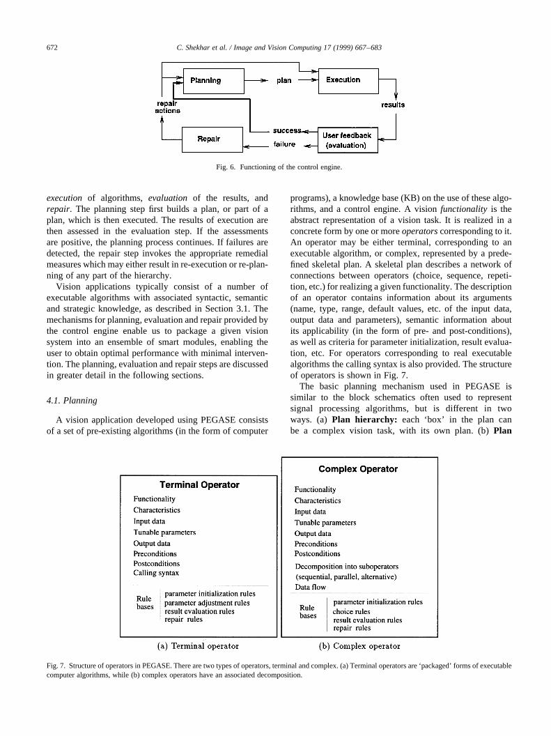
execution of algorithms, evaluation of the results, andrepair. The planning step first builds a plan, or part of aplan, which is then executed. The results of execution arethen assessed in the evaluation step. If the assessmentsare positive, the planning process continues. If failures aredetected, the repair step invokes the appropriate remedialmeasures which may either result in re-execution or re-plan-ning of any part of the hierarchy.
Vision applications typically consist of a number ofexecutable algorithms with associated syntactic, semanticand strategic knowledge, as described in Section 3.1. Themechanisms for planning, evaluation and repair provided bythe control engine enable us to package a given visionsystem into an ensemble of smart modules, enabling theuser to obtain optimal performance with minimal interven-tion. The planning, evaluation and repair steps are discussedin greater detail in the following sections.
4.1. Planning
A vision application developed using PEGASE consistsof a set of pre-existing algorithms (in the form of computer
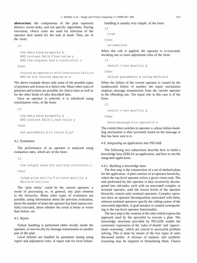
programs), a knowledge base (KB) on the use of these algo-rithms, and a control engine. A visionfunctionality is theabstract representation of a vision task. It is realized in aconcrete form by one or moreoperatorscorresponding to it.An operator may be either terminal, corresponding to anexecutable algorithm, or complex, represented by a prede-fined skeletal plan. A skeletal plan describes a network ofconnections between operators (choice, sequence, repeti-tion, etc.) for realizing a given functionality. The descriptionof an operator contains information about its arguments(name, type, range, default values, etc. of the input data,output data and parameters), semantic information aboutits applicability (in the form of pre- and post-conditions),as well as criteria for parameter initialization, result evalua-tion, etc. For operators corresponding to real executablealgorithms the calling syntax is also provided. The structureof operators is shown in Fig. 7.
The basic planning mechanism used in PEGASE issimilar to the block schematics often used to representsignal processing algorithms, but is different in twoways. (a) Plan hierarchy: each ‘box’ in the plan canbe a complex vision task, with its own plan. (b)Plan
C. Shekhar et al. / Image and Vision Computing 17 (1999) 667–683672
Fig. 6. Functioning of the control engine.
Fig. 7. Structure of operators in PEGASE. There are two types of operators, terminal and complex. (a) Terminal operators are ‘packaged’ forms of executablecomputer algorithms, while (b) complex operators have an associated decomposition.
abstraction: the components of the plan representabstract vision tasks, and not specific algorithms. Duringexecution, choice rules are used for selection of theoperator best suited for the task at hand. They are ofthe form:
if
the data have property xAND context field f has value yAND the request has a constraint z
then
choose an operator with characteristic bAND do not choose operator w
The above example shows only some of the possible typesof premises and actions in a choice rule. Many other types ofpremises and actions are possible, for choice rules as well asfor the other kinds of rules described later.
Once an operator is selected, it is initialized usinginitialization rules, of the form:
if
the data have property xAND context field c f has value y
then
set parameter p to value f x( y)
4.2. Evaluation
The performance of an operator is analyzed usingevaluation rules, which are of the form:
if
the output does not satisfy criterion c
then
judge plan entity P to have quality qdeclare failure
The ‘plan entity’ could be the current operator, aresult of processing or, in general, any plan elementin the hierarchy. Many other types of evaluation arepossible, using information about the previous evaluation,about the number of times the operator has been (unsuccess-fully) executed, about whether the result is better or worsethan before, etc.
4.3. Repair
Failure handling is performed either locally inside theoperator, or non-locally by message transmission to anotherpart of the plan.
Local failures are handled by parameter tuning usingrepair andadjustment rules. A repair rule for local failure-
handling is usually very simple, of the form:
if
true
then
re-execute
When this rule is applied, the operator is re-executed,invoking one or more adjustment rules of the form:
if
result r has quality q
then
adjust parameter p using method m
When the failure of the current operator is caused by the(undetected) failure of another, the repair mechanismemploys message transmission from the current operatorto the offending one. The repair rule in this case is of theform:
if
result r has quality q
then
send message mto operator o
The control then switches to operatoro, whose failure-hand-ling mechanism is then activated, based on the messagemthat has been sent to it.
4.4. Integrating an application into PEGASE
The following two subsections describe how to build aknowledge base (KB) for an application, and how to run theintegrated application.
4.4.1. Building a knowledge baseThe first step is the construction of a set of skeletal plans
for the application. A plan consists of an operator hierarchy,where the top-level operator solves a given vision task. Thetask performed by this operator is then recursively decom-posed into sub-tasks, each with an associated complex orterminal operator, until the lowest levels of the operatorhierarchy contain only terminal operators. Complex opera-tors have an operator decomposition associated with them,whereas terminal operators specify the calling syntax of theassociated algorithm. A goal instance is created correspond-ing to the top-level operator functionality.
The next step is the creation of the rules which express theapproach used by the specialist to execute a plan. Theknowledge structures provided by PEGASE enable thesystematic expression of the ‘rules of thumb’ and ‘approx-imate reasoning,’ which are crucial to successful problemsolving. This is done by means of the five types of rulesdiscussed earlier. A mixture of numeric and symbolicreasoning may be required in formulating them. Choice
C. Shekhar et al. / Image and Vision Computing 17 (1999) 667–683 673
rules, being the simplest, are defined first. They use thevalues of context fields, data definitions, constraints in therequest, etc., to select an operator from among the choicesavailable. Initialization rules are defined next. These may besomewhat more difficult, in that they have to formalize the‘rough initial guesses’ that the specialist makes before start-ing an vision task. Adjustment rules are then defined foroperators which have adjustable parameters. Step sizes forparameters have to be carefully chosen so that the change inthe behavior of the algorithm is neither too sudden nor toogradual. Then evaluation rules are defined. This is a ratherdifficult task, since the question “Are the results goodenough?” is often subjective, and appropriate qualitymeasures may not be readily available. However, a closeexamination of the specialist’s problem-solving techniqueoften reveals hidden reasoning capable of being expressedin concrete terms as evaluation rules. Finally, the repairrules are defined. These rules determine the overall fail-ure-handling mechanism, and are crucial to the success ofthe application.
4.4.2. Running an applicationThe solving of a problem starts with the creation of a
request, which states the functionality, the data on whichthis is to be achieved, and the context in which the problemis being solved. Using choice rules, the available operatorsfor the functionality are rank-ordered. The best operator isselected, and executed on the given data after the operator’sinitialization rules have been applied. If the operator is aterminal one, this corresponds to the execution of the corre-sponding algorithm. If it is a complex one, its children are
pushed onto an execution stack, to be examined in turn andexecuted depending on their sequencing. If the mode ofexecution control calls for it, the results of executing anoperator are judged using evaluation rules and, in theevent of a failure, either the same operator is re-executedafter its parameters have been adjusted using the relevantrules, or the next best operator is applied. In the event ofsuccessful execution, the next operator in the sequence isselected for execution. This continues until the executionstack is empty. It is to be noted that, during this wholeprocess, the knowledge base is not modified at all, i.e.there is no learning taking place. Only the choice of algo-rithms and parameters is modified. The knowledge base iscreated off-line, and provided at the outset.
The next two sections illustrate our approach using tworeal applications. The first application, synthetic apertureradar (SAR) image analysis, illustrates the specialist modeof self-tuning, while the second application, vehicle detec-tion, illustrates the user mode.
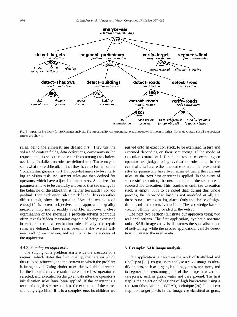
5. Example: SAR image analysis
This application is based on the work of Kuttikkad andChellappa [20]. Its goal is to analyze a SAR image to iden-tify objects, such as targets, buildings, roads, and trees, andto segment the remaining parts of the image into variouscategories, such as grass, water and bare ground. The firststep is the detection of regions of high backscatter using aconstant false alarm rate (CFAR) technique [20]. In the nextstep, non-target pixels in the image are classified as grass,
C. Shekhar et al. / Image and Vision Computing 17 (1999) 667–683674
Fig. 8. Operator hierarchy for SAR image analysis. The functionality corresponding to each operator is shown in italics. To avoid clutter, not all theoperatornames are shown.

tree, bare ground, road or shadow using a maximum like-lihood (ML) approach. Training data obtained from otherimages of similar scenes is employed. This is a preliminaryclassification, using no high-level information whatsoever.A large percentage of the pixels are likely to be misclassi-fied.
Shadow regions are detected and then eroded and grownusing morphological operations. The same is done for pixelsclassified as road. Very small regions of either class areeliminated, and the rest are grouped into homogeneousregions. Shadow regions that are adjacent to a bright streak(in the CFAR output) towards the sensor are classified asbuilding shadows. Roads are verified using a shape/sizecriterion. ML segmentation is then repeated for pixelspreviously misclassified as road and shadow, this time clas-sifying them as grass, bare ground or trees. Tree regions aregrown using morphological operations, and verified using asize argument, as well as by the presence of adjoiningshadow regions away from the sensor. In the CFAR output,streaks corresponding to buildings are eliminated, and theremaining target pixels are grouped into clusters. In the finalstep, ML segmentation is repeated, and based on the
previous steps, pixels misclassified as shadow, road or treeare re-classified into grass or bare ground (Fig. 8). Sampleresults obtained by the approach are shown in Fig. 9.
5.1. Knowledge base
The hierarchy of operators for this application is shown inFig. 8. The knowledge base consists of the following majorcomponents: 21 operators (13 terminal and seven complex),18 sequential and two choice links, and a total of 29 produc-tion rules (two choice, 10 initialization, six evaluation, sixadjustment and five repair). Some simple examples fromthis KB are presented to give the reader a feel for thekinds of objects and reasoning involved in a real application.
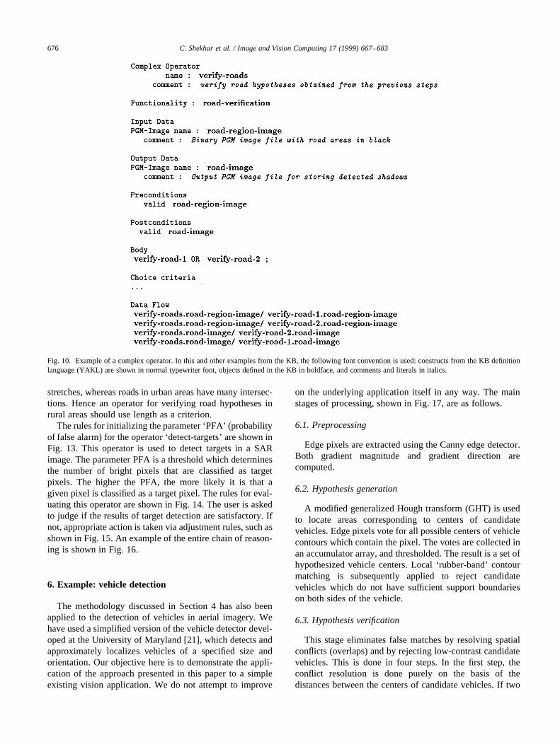
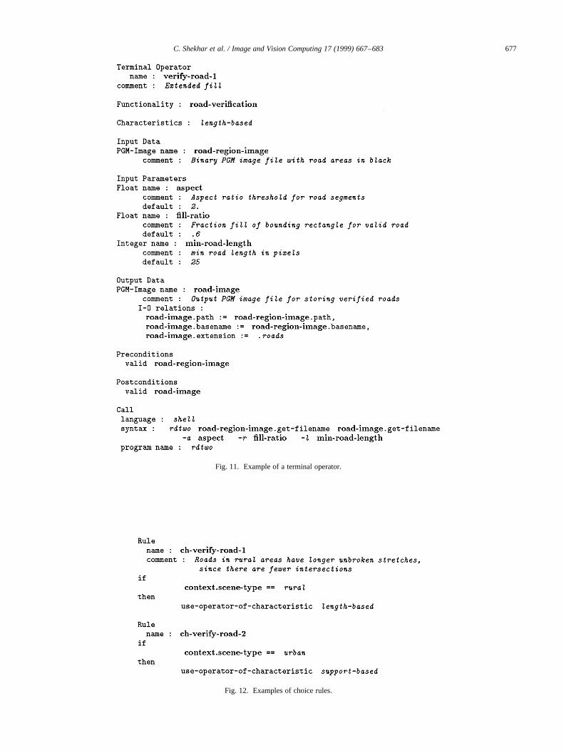
An example of a complex operator is shown in Fig. 10.The functionality is road verification, which verifies roadhypotheses obtained by pixel classification and region grow-ing. This operator has a decomposition into a choicebetween two terminal operators, one of which is shown inFig. 11. The choice rules for deciding which operator toselect are shown in Fig. 12. The reasoning is as follows:in rural areas, roads are likely to have longer unbroken
C. Shekhar et al. / Image and Vision Computing 17 (1999) 667–683 675
Fig. 9. Sample results of SAR image analysis.
stretches, whereas roads in urban areas have many intersec-tions. Hence an operator for verifying road hypotheses inrural areas should use length as a criterion.
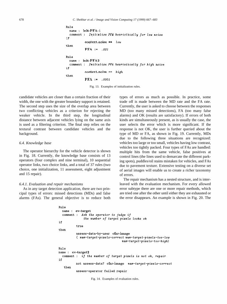
The rules for initializing the parameter ‘PFA’ (probabilityof false alarm) for the operator ‘detect-targets’ are shown inFig. 13. This operator is used to detect targets in a SARimage. The parameter PFA is a threshold which determinesthe number of bright pixels that are classified as targetpixels. The higher the PFA, the more likely it is that agiven pixel is classified as a target pixel. The rules for eval-uating this operator are shown in Fig. 14. The user is askedto judge if the results of target detection are satisfactory. Ifnot, appropriate action is taken via adjustment rules, such asshown in Fig. 15. An example of the entire chain of reason-ing is shown in Fig. 16.
6. Example: vehicle detection
The methodology discussed in Section 4 has also beenapplied to the detection of vehicles in aerial imagery. Wehave used a simplified version of the vehicle detector devel-oped at the University of Maryland [21], which detects andapproximately localizes vehicles of a specified size andorientation. Our objective here is to demonstrate the appli-cation of the approach presented in this paper to a simpleexisting vision application. We do not attempt to improve
on the underlying application itself in any way. The mainstages of processing, shown in Fig. 17, are as follows.
6.1. Preprocessing
Edge pixels are extracted using the Canny edge detector.Both gradient magnitude and gradient direction arecomputed.
6.2. Hypothesis generation
A modified generalized Hough transform (GHT) is usedto locate areas corresponding to centers of candidatevehicles. Edge pixels vote for all possible centers of vehiclecontours which contain the pixel. The votes are collected inan accumulator array, and thresholded. The result is a set ofhypothesized vehicle centers. Local ‘rubber-band’ contourmatching is subsequently applied to reject candidatevehicles which do not have sufficient support boundarieson both sides of the vehicle.
6.3. Hypothesis verification
This stage eliminates false matches by resolving spatialconflicts (overlaps) and by rejecting low-contrast candidatevehicles. This is done in four steps. In the first step, theconflict resolution is done purely on the basis of thedistances between the centers of candidate vehicles. If two
C. Shekhar et al. / Image and Vision Computing 17 (1999) 667–683676
Fig. 10. Example of a complex operator. In this and other examples from the KB, the following font convention is used: constructs from the KB definitionlanguage (YAKL) are shown in normal typewriter font, objects defined in the KB in boldface, and comments and literals in italics.
C. Shekhar et al. / Image and Vision Computing 17 (1999) 667–683 677
Fig. 11. Example of a terminal operator.
Fig. 12. Examples of choice rules.
candidate vehicles are closer than a certain fraction of theirwidth, the one with the greater boundary support is retained.The second step uses the size of the overlap area betweentwo conflicting vehicles as a criterion for rejecting theweaker vehicle. In the third step, the longitudinaldistance between adjacent vehicles lying on the same axisis used as a filtering criterion. The final step relies on thetextural contrast between candidate vehicles and thebackground.
6.4. Knowledge base
The operator hierarchy for the vehicle detector is shownin Fig. 18. Currently, the knowledge base consists of 13operators (four complex and nine terminal), 10 sequentialoperator links, two choice links, and a total of 37 rules (twochoice, one initialization, 11 assessment, eight adjustmentand 15 repair).
6.4.1. Evaluation and repair mechanismsAs in any target detection application, there are two prin-
cipal types of errors: missed detections (MDs) and falsealarms (FAs). The general objective is to reduce both
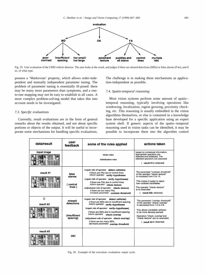
types of errors as much as possible. In practice, sometrade off is made between the MD rate and the FA rate.Currently, the user is asked to choose between the responsesMD (too many missed detections), FA (too many falsealarms) and OK (results are satisfactory). If errors of bothkinds are simultaneously present, as is usually the case, theuser selects the error which is more significant. If theresponse is not OK, the user is further queried about thetype of MD or FA, as shown in Fig. 19. Currently, MDsdue to the following three situations are recognized:vehicles too large or too small, vehicles having low contrast,vehicles too tightly packed. Four types of FAs are handled:multiple hits from the same vehicle, false positives atcontrol lines (the lines used to demarcate the different park-ing spots), puddles/oil stains mistaken for vehicles, and FAsdue to pavement texture. Extensive testing on a diverse setof aerial images will enable us to create a richer taxonomyof errors.
The repair mechanism has a nested structure, and is inter-leaved with the evaluation mechanism. For every allowederror subtype there are one or more repair methods, whichare tried one after the other until either they are exhausted orthe error disappears. An example is shown in Fig. 20. The
C. Shekhar et al. / Image and Vision Computing 17 (1999) 667–683678
Fig. 13. Examples of initialization rules.
Fig. 14. Examples of evaluation rules.
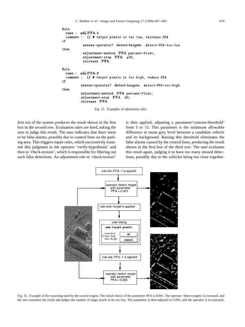
first run of the system produces the result shown in the firstbox in the second row. Evaluation rules are fired, asking theuser to judge this result. The user indicates that there seemto be false alarms, possibly due to control lines on the park-ing area. This triggers repair rules, which successively trans-mit this judgment to the operator ‘verify-hypotheses’ andthen to ‘check-texture’, which is responsible for filtering outsuch false detections. An adjustment rule in ‘check-texture’
is then applied, adjusting a parameter‘contrast-threshold’from 5 to 15. This parameter is the minimum allowabledifference in mean grey level between a candidate vehicleand its background. Raising this threshold eliminates thefalse alarms caused by the control lines, producing the resultshown in the first box of the third row. The user evaluatesthis result again, judging it to have too many missed detec-tions, possibly due to the vehicles being too close together.
C. Shekhar et al. / Image and Vision Computing 17 (1999) 667–683 679
Fig. 15. Examples of adjustment rules.
Fig. 16. Example of the reasoning used by the control engine. The initial choice of the parameter PFA is 0.001. The operator ‘detect-targets’ is executed, andthe user examines the result and judges the number of target pixels to be too low. The parameter is then adjusted to 0.005, and the operator is re-executed.

This judgment triggers a sequence of repair and adjustmentrules, resulting in the decrement of a parameter whichspecifies the factor by which vehicles have to be scaledbefore deciding that they overlap. This allows candidatevehicles spaced closer together to be judged as non-overlapping, and hence acceptable. The final result, whichthe user judges to be ‘OK’, is shown in the first box on thelast row.
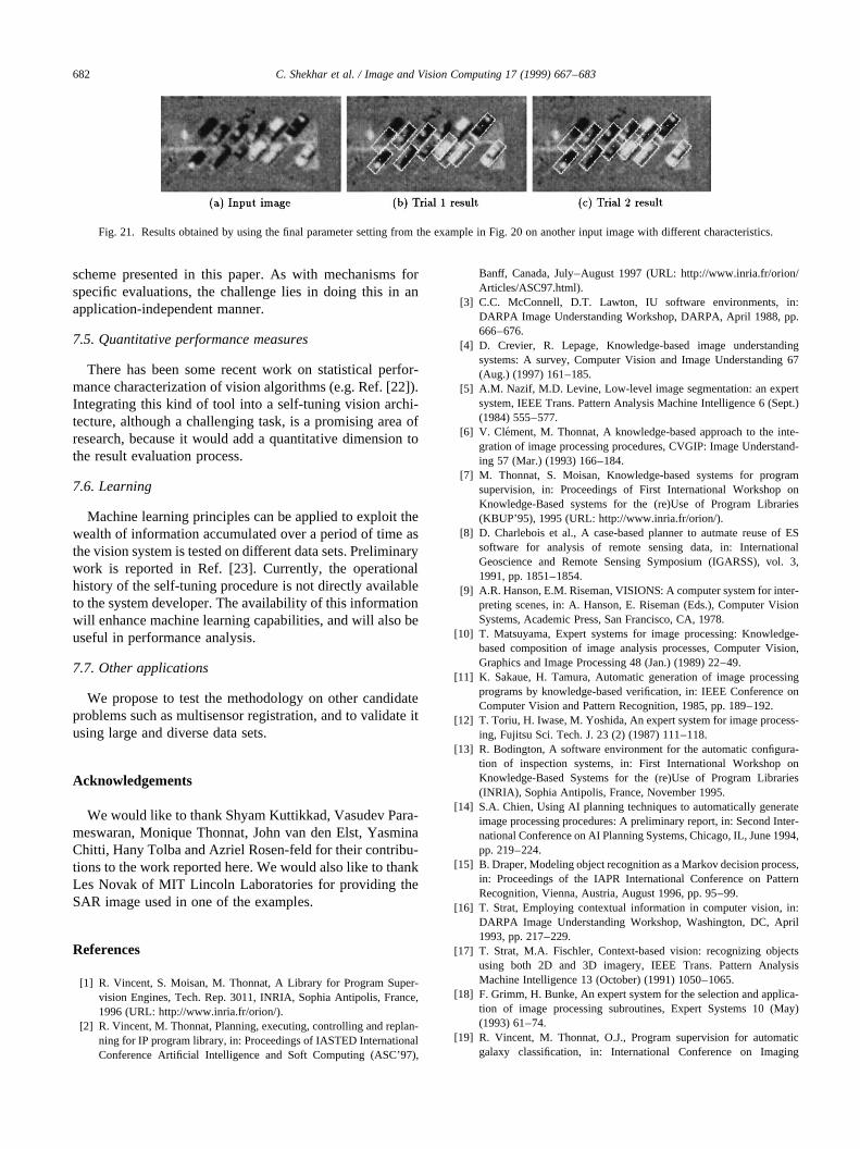
At the end of this process, we are left with a parametersetting which is optimal for input images with characteris-tics similar to the one used in Fig. 20. If this parametersetting is used on a very different type of input image, wemay not obtain comparable results. In Fig. 21, we show theresults on another input image using this parameter setting.This input image (Fig. 21a) has a different texture, and thevehicles are oriented differently. As a result, the result of thefirst trial (Fig. 21b) is unsatisfactory. As in the previouscase, the user judges that there are missed detections dueto the vehicles being too close together. This triggers thesame repair/adjustment sequence as before, producing theresult in (Fig. 21c).
7. Conclusions and future work
This paper has presented a methodology for adding flex-ibility and convenience to an existing vision system by inte-grating the vision specialist’s knowledge into it using aknowledge-based architecture. The proposed methodologyassumes that the vision system has a non-empty operatingregion at which it yields satisfactory results. It imitates theapproach used by the specialist in reaching a point in thisregion from a given or default setting. The system can thusself-tune in response to the user’s evaluations. This type of asystem will be of immense value in making the full power ofvision algorithms available to end-users. Here are somepossible directions for future work:
7.1. Detecting failure
Obviously, if no combination of the tuning parameterscan yield satisfactory results, neither the specialist nor theself-tuning framework will have any chance of succeeding.On the other hand, if the self-tuning mechanism does notcapture the full complexity of the specialist’s reasoning, itmay fail in difficult cases even if a solution exists. Detectingthis failure may not always be easy for the user, since theself-tuning mechanism may have loops and other complexchains of reasoning. If the system does not solve theproblem in a reasonable amount of time, it should be consid-ered as having failed. Experimentation on large and diversedata sets and constant refinement of the knowledge base willensure that such failures do not occur too often.
7.2. Validity of the model
Closely related to the problem of detecting failures is thevalidation of the basic self-tuning model itself. This modelassumes that based on certain‘symptoms’ of the result, adiagnosis can be made as to which parameter (or algorithm)is at fault. As in Ref. [15], the vision system is assumed to
C. Shekhar et al. / Image and Vision Computing 17 (1999) 667–683680
Fig. 17. A simplified version of the UMD vehicle detector. The input is anaerial image. Contours are extracted, and vehicle hypotheses are generated.These hypotheses are then validated to obtain the final result.
Fig. 18. Operator hierarchy for the UMD vehicle detector. The functionality corresponding to each operator is shown in italics.
possess a ‘Markovian’ property, which allows order-inde-pendent and mutually independent parameter tuning. Theproblem of parameter tuning is essentially ill-posed: theremay be many more parameters than symptoms, and a one-to-one mapping may not be easy to establish in all cases. Amore complex problem-solving model that takes this intoaccount needs to be investigated.
7.3. Specific evaluations
Currently, result evaluations are in the form of generalremarks about the results obtained, and not about specificportions or objects of the output. It will be useful to incor-porate some mechanisms for handling specific evaluations.
The challenge is in making these mechanisms as applica-tion-independent as possible.
7.4. Spatio-temporal reasoning
Most vision systems perform some amount of spatio–temporal reasoning, typically involving operations likewindowing, localization, region growing, proximity check-ing, etc. This reasoning is usually embedded in the visionalgorithms themselves, or else is contained in a knowledgebase developed for a specific application using an expertsystem shell. If generic aspects of the spatio–temporalreasoning used in vision tasks can be identified, it may bepossible to incorporate them into the algorithm control
C. Shekhar et al. / Image and Vision Computing 17 (1999) 667–683 681
Fig. 19. User evaluation of the UMD vehicle detector. The user looks at the result, and judges if there are missed detections (MDs) or false alarms (FAs), and ifso, of what type.
Fig. 20. Example of the execution–evaluation–repair cycle.
scheme presented in this paper. As with mechanisms forspecific evaluations, the challenge lies in doing this in anapplication-independent manner.
7.5. Quantitative performance measures
There has been some recent work on statistical perfor-mance characterization of vision algorithms (e.g. Ref. [22]).Integrating this kind of tool into a self-tuning vision archi-tecture, although a challenging task, is a promising area ofresearch, because it would add a quantitative dimension tothe result evaluation process.
7.6. Learning
Machine learning principles can be applied to exploit thewealth of information accumulated over a period of time asthe vision system is tested on different data sets. Preliminarywork is reported in Ref. [23]. Currently, the operationalhistory of the self-tuning procedure is not directly availableto the system developer. The availability of this informationwill enhance machine learning capabilities, and will also beuseful in performance analysis.
7.7. Other applications
We propose to test the methodology on other candidateproblems such as multisensor registration, and to validate itusing large and diverse data sets.
Acknowledgements
We would like to thank Shyam Kuttikkad, Vasudev Para-meswaran, Monique Thonnat, John van den Elst, YasminaChitti, Hany Tolba and Azriel Rosen-feld for their contribu-tions to the work reported here. We would also like to thankLes Novak of MIT Lincoln Laboratories for providing theSAR image used in one of the examples.
References
[1] R. Vincent, S. Moisan, M. Thonnat, A Library for Program Super-vision Engines, Tech. Rep. 3011, INRIA, Sophia Antipolis, France,1996 (URL: http://www.inria.fr/orion/).
[2] R. Vincent, M. Thonnat, Planning, executing, controlling and replan-ning for IP program library, in: Proceedings of IASTED InternationalConference Artificial Intelligence and Soft Computing (ASC’97),
Banff, Canada, July–August 1997 (URL: http://www.inria.fr/orion/Articles/ASC97.html).
[3] C.C. McConnell, D.T. Lawton, IU software environments, in:DARPA Image Understanding Workshop, DARPA, April 1988, pp.666–676.
[4] D. Crevier, R. Lepage, Knowledge-based image understandingsystems: A survey, Computer Vision and Image Understanding 67(Aug.) (1997) 161–185.
[5] A.M. Nazif, M.D. Levine, Low-level image segmentation: an expertsystem, IEEE Trans. Pattern Analysis Machine Intelligence 6 (Sept.)(1984) 555–577.
[6] V. Clement, M. Thonnat, A knowledge-based approach to the inte-gration of image processing procedures, CVGIP: Image Understand-ing 57 (Mar.) (1993) 166–184.
[7] M. Thonnat, S. Moisan, Knowledge-based systems for programsupervision, in: Proceedings of First International Workshop onKnowledge-Based systems for the (re)Use of Program Libraries(KBUP’95), 1995 (URL: http://www.inria.fr/orion/).
[8] D. Charlebois et al., A case-based planner to autmate reuse of ESsoftware for analysis of remote sensing data, in: InternationalGeoscience and Remote Sensing Symposium (IGARSS), vol. 3,1991, pp. 1851–1854.
[9] A.R. Hanson, E.M. Riseman, VISIONS: A computer system for inter-preting scenes, in: A. Hanson, E. Riseman (Eds.), Computer VisionSystems, Academic Press, San Francisco, CA, 1978.
[10] T. Matsuyama, Expert systems for image processing: Knowledge-based composition of image analysis processes, Computer Vision,Graphics and Image Processing 48 (Jan.) (1989) 22–49.
[11] K. Sakaue, H. Tamura, Automatic generation of image processingprograms by knowledge-based verification, in: IEEE Conference onComputer Vision and Pattern Recognition, 1985, pp. 189–192.
[12] T. Toriu, H. Iwase, M. Yoshida, An expert system for image process-ing, Fujitsu Sci. Tech. J. 23 (2) (1987) 111–118.
[13] R. Bodington, A software environment for the automatic configura-tion of inspection systems, in: First International Workshop onKnowledge-Based Systems for the (re)Use of Program Libraries(INRIA), Sophia Antipolis, France, November 1995.
[14] S.A. Chien, Using AI planning techniques to automatically generateimage processing procedures: A preliminary report, in: Second Inter-national Conference on AI Planning Systems, Chicago, IL, June 1994,pp. 219–224.
[15] B. Draper, Modeling object recognition as a Markov decision process,in: Proceedings of the IAPR International Conference on PatternRecognition, Vienna, Austria, August 1996, pp. 95–99.
[16] T. Strat, Employing contextual information in computer vision, in:DARPA Image Understanding Workshop, Washington, DC, April1993, pp. 217–229.
[17] T. Strat, M.A. Fischler, Context-based vision: recognizing objectsusing both 2D and 3D imagery, IEEE Trans. Pattern AnalysisMachine Intelligence 13 (October) (1991) 1050–1065.
[18] F. Grimm, H. Bunke, An expert system for the selection and applica-tion of image processing subroutines, Expert Systems 10 (May)(1993) 61–74.
[19] R. Vincent, M. Thonnat, O.J., Program supervision for automaticgalaxy classification, in: International Conference on Imaging
C. Shekhar et al. / Image and Vision Computing 17 (1999) 667–683682
Fig. 21. Results obtained by using the final parameter setting from the example in Fig. 20 on another input image with different characteristics.

Science, Systems and Technology (CISST’97), Las Vegas, NV, June1997.
[20] S. Kuttikkad, R. Chellappa, Building wide area 2D site models fromhigh resolution polarimetric synthetic aperture radar images, Tech.Rep. CAR-TR-776, Computer Vision Laboratory, University ofMaryland, College Park, MD 20742-3275, June 1995.
[21] R. Chellappa, X. Zhang, P. Burlina, C.L. Lin, Q. Zheng, L.S. Davis,A. Rosenfeld, An integrated system for site-model supported moni-toring of transportation activities in aerial images, in: DARPA Image
Understanding Workshop, vol. 1, Palm Springs, CA, February 1996,pp. 275–304.
[22] X. Liu, T. Kanungo, R.M. Haralick, Statistical validation of computervision software, in: DARPA Image Understanding Workshop, vol. 2,Palm Springs, CA, February 1996, pp. 1533–1540.
[23] R. Vincent, S. Moisan, M. Thonnat, Learning as a means to refine aknowledge-based system, in: Proceedings of Third Japanese Knowl-edge Acquisition for Knowledge-Based Systems Workshop,Hatoyama, Japan, November 1994, pp. 17–31.
C. Shekhar et al. / Image and Vision Computing 17 (1999) 667–683 683