Embed Size (px)
Citation preview

Eindhoven University of Technology
MASTER
Knowledge needed to develop malware to infect and impact industrial control systems
van de Wouw, D.A.
Award date:2013
Link to publication
DisclaimerThis document contains a student thesis (bachelor's or master's), as authored by a student at Eindhoven University of Technology. Studenttheses are made available in the TU/e repository upon obtaining the required degree. The grade received is not published on the documentas presented in the repository. The required complexity or quality of research of student theses may vary by program, and the requiredminimum study period may vary in duration.
General rightsCopyright and moral rights for the publications made accessible in the public portal are retained by the authors and/or other copyright ownersand it is a condition of accessing publications that users recognise and abide by the legal requirements associated with these rights.
• Users may download and print one copy of any publication from the public portal for the purpose of private study or research. • You may not further distribute the material or use it for any profit-making activity or commercial gain
Department of Mathematics andComputer ScienceDen Dolech 2, 5612 AZ EindhovenP.O. Box 513, 5600 MB EindhovenThe Netherlandswww.tue.nl
Supervisorprof.dr. Sandro Etalle (TU/e)
SectionSecurity group
SupervisorTrajce Dimkov, PhD (Deloitte)
SectionSecurity and Privacy
DateOctober 21, 2013
Version1.0
Knowledge needed to develop malware to infectand impact Industrial Control Systems
Master’s Thesis
D.A. van de Wouw

ii

ChapterExecutive Summary
Industrial Control Systems (ICSs) have been with us for more than five decades. They are used to perform a broadrange of automated tasks, such as the production of food, drinks, electricity and oil. ICSs are also used to controlservices like traffic lights, safe railroad crossings or transport luggage on an airport conveyor belt. Some ICSs arecritical to society, like a power plant: households can experience a black-out if a power plant stops working.
ICSs were initially communicating through proprietary control protocols on specialized hardware and software,isolated from the rest of the world. Later, standardized communication protocols, hardware and software wereintroduced and recently businesses have started to integrate ICS with regular Information Technology (IT).These changes enable new functionality but also imply that ICSs become more accessible to the outside worldand IT problems, including malicious software (malware), become a threat to ICS networks.
Malware is omnipresent and malware is now able to reach ICSs. This could cause financial loss or physical damage.Developing malware that can infect and impact ICSs requires a certain amount of prior system knowledge. Ifthe information needed to develop malware for a specific target was kept secret by ICS managers/employees, itwould be harder to target that ICS using malware.
This brought up the research question: “What system knowledge is needed for a malware developer to create malwareto infect and impact an Industrial Control System?”. We divided it into two sub-questions, the first is about theknowledge needed to infect ICSs and the second about the knowledge needed to impact the security of ICSs.
We first set up an environment to represent a chemical plant which contained drums, pumps and valves. Then,we developed malware that was able to infect the plant and impact the integrity and availability by disruptingplant supervision and overflowing or emptying the drums.
A list of possible environmental changes was prepared which was reviewed and completed by ICS and malwarespecialists. We changed the environment according to an item on the list and determined if the change reducedor diminished the effects of the malware. System knowledge was needed if the malware was unable to infect orimpact the security of the plant when this was not caused by a design decision. These findings were analyzedand together with the learned lessons the sub-questions were answered.
The outcome of the thesis was that malware developers need to acquire certain knowledge to launch a targetedattack on an ICS. If an attacker wants to impact the security of the ICS with malware, he needs to infect the ICSfirst. This requires knowledge about what Operating Systems (OSs) (e.g., Windows, Linux) need to be infected.One or more exploits compatible with the OS are needed to infect the targeted machines. Knowledge about theOS version is needed, depending on the vulnerabilities that the exploits target. If the target is not connectedto the Internet (i.e., completely air-gapped) then an attack scenario with corresponding exploits is needed (e.g.,a scenario where the malware infects USB-drives). Knowledge about firewalls and their rules will enable theattacker to develop malware that can spread and scan through networks without being blocked. The attackershould know a (unique) property of the target for the malware to detect if it has reached its target.
If the malware reaches a machine that can control the environment it will try to impact the integrity and/oravailability of the system. If the malware can create a backdoor that is able to communicate with a commandand control server, then it becomes possible for the attacker to analyze the environment manually. Otherwise,more knowledge would be needed during development, such as knowledge about the physical processes that arecontrolled by the ICS and how the processes are controlled. Knowledge about the (Supervisory Control and DataAcquisition (SCADA) or Human Machine Interface (HMI)) software used at the ICS can be used to develop extraexploits and enumerate connected Programmable Logic Controllers (PLCs) at runtime.
The main impact of the research is that it provides a list of system knowledge that is needed to develop malwareto infect and impact the security of an ICS. As part of their defence in depth strategy, ICS staff should keep theinformation described here secret to make it harder for malware developers to launch targeted attacks.
iii

iv
ChapterAcknowledgements
While I wrote my thesis I had a lot of support from colleagues at Deloitte, family and friends. I would like totake this opportunity to thank them. First, I want to thank my supervisors Trajce Dimkov and Sandro Etalle forguiding me through the process of performing research, reviewing my thesis and providing useful insights. Iwould like to thank Dmitri Jarnikov for being a voting member in the assessment committee.Then I would like to thank my colleagues from the Security and Privacy team of Deloitte for the interestingdiscussions and for creating a fun environment to work in. I want to thank Floris Schoenmakers and SergioHernando for sharing their knowledge about Industrial Control Systems. I also want to thank Thijs Bosschert forgetting me up to speed with malware (development). I would like to thank Spase Stojanovski for his opinion andsuggestions regarding the setup of an Industrial Control System environment. I want to thank the participants ofthe questionnaire for providing valuable feedback. Finally, I would like to thank my family, friends, and girlfriendfor their support.
v

vi
ChapterContents
Executive Summary iii
Acknowledgements v
1 Introduction 1
1.1 Scenario . . . . . . . . . . . . . . . . . . . . . . . . . . . . . . . . . . . . . . . . . . . . . . . . . . 1
1.2 Problem description . . . . . . . . . . . . . . . . . . . . . . . . . . . . . . . . . . . . . . . . . . . . 2
1.3 Research question . . . . . . . . . . . . . . . . . . . . . . . . . . . . . . . . . . . . . . . . . . . . . 2
1.4 Research method . . . . . . . . . . . . . . . . . . . . . . . . . . . . . . . . . . . . . . . . . . . . . 3
1.5 Contribution . . . . . . . . . . . . . . . . . . . . . . . . . . . . . . . . . . . . . . . . . . . . . . . . 3
1.6 Thesis structure . . . . . . . . . . . . . . . . . . . . . . . . . . . . . . . . . . . . . . . . . . . . . . 4
2 Industrial Control Systems 5
2.1 History . . . . . . . . . . . . . . . . . . . . . . . . . . . . . . . . . . . . . . . . . . . . . . . . . . . 5
2.2 Control Theory . . . . . . . . . . . . . . . . . . . . . . . . . . . . . . . . . . . . . . . . . . . . . . 6
2.3 Architecture . . . . . . . . . . . . . . . . . . . . . . . . . . . . . . . . . . . . . . . . . . . . . . . . 6
2.3.1 Level 0 - Processes . . . . . . . . . . . . . . . . . . . . . . . . . . . . . . . . . . . . . . . . 6
2.3.2 Level 1 - Basic Control . . . . . . . . . . . . . . . . . . . . . . . . . . . . . . . . . . . . . . 7
2.3.3 Level 2 - Area Control . . . . . . . . . . . . . . . . . . . . . . . . . . . . . . . . . . . . . . 8
2.3.4 Level 3 - Site Control . . . . . . . . . . . . . . . . . . . . . . . . . . . . . . . . . . . . . . . 8
2.3.5 Level 4 and 5 - Enterprise zone . . . . . . . . . . . . . . . . . . . . . . . . . . . . . . . . . 8
2.3.6 Demilitarized zone (DMZ) . . . . . . . . . . . . . . . . . . . . . . . . . . . . . . . . . . . . 8
2.4 Comparison of ICS and IT . . . . . . . . . . . . . . . . . . . . . . . . . . . . . . . . . . . . . . . . 9
3 Experimental environment 11
3.1 Scenario . . . . . . . . . . . . . . . . . . . . . . . . . . . . . . . . . . . . . . . . . . . . . . . . . . 11
3.2 Components . . . . . . . . . . . . . . . . . . . . . . . . . . . . . . . . . . . . . . . . . . . . . . . . 13
3.2.1 HMI software . . . . . . . . . . . . . . . . . . . . . . . . . . . . . . . . . . . . . . . . . . . 13
3.2.2 Programmable Logic Controller (PLC) . . . . . . . . . . . . . . . . . . . . . . . . . . . . . 14
3.3 Physical processes . . . . . . . . . . . . . . . . . . . . . . . . . . . . . . . . . . . . . . . . . . . . . 15
3.4 Malware . . . . . . . . . . . . . . . . . . . . . . . . . . . . . . . . . . . . . . . . . . . . . . . . . . 16
3.4.1 ICS targeted malware . . . . . . . . . . . . . . . . . . . . . . . . . . . . . . . . . . . . . . . 16
vii
Chapter 0. Contents
3.4.2 IT targeted malware . . . . . . . . . . . . . . . . . . . . . . . . . . . . . . . . . . . . . . . 16
3.4.3 Custom ICS tailored malware . . . . . . . . . . . . . . . . . . . . . . . . . . . . . . . . . . 17
4 Results 23
4.1 Methodology . . . . . . . . . . . . . . . . . . . . . . . . . . . . . . . . . . . . . . . . . . . . . . . . 23
4.2 Default environment . . . . . . . . . . . . . . . . . . . . . . . . . . . . . . . . . . . . . . . . . . . 24
4.3 Environmental change results . . . . . . . . . . . . . . . . . . . . . . . . . . . . . . . . . . . . . . 27
4.3.1 Example of an environmental change . . . . . . . . . . . . . . . . . . . . . . . . . . . . . . 27
4.3.2 Summary . . . . . . . . . . . . . . . . . . . . . . . . . . . . . . . . . . . . . . . . . . . . . 29
5 Analysis 35
5.1 Analysis methodology . . . . . . . . . . . . . . . . . . . . . . . . . . . . . . . . . . . . . . . . . . 35
5.2 System knowledge needed to infect ICSs . . . . . . . . . . . . . . . . . . . . . . . . . . . . . . . . 35
5.2.1 Analysis of environmental changes . . . . . . . . . . . . . . . . . . . . . . . . . . . . . . . 35
5.2.2 Lessons learned . . . . . . . . . . . . . . . . . . . . . . . . . . . . . . . . . . . . . . . . . . 35
5.2.3 Conclusion . . . . . . . . . . . . . . . . . . . . . . . . . . . . . . . . . . . . . . . . . . . . 38
5.3 System knowledge needed to impact the security of ICSs . . . . . . . . . . . . . . . . . . . . . . . 39
5.3.1 Analysis of environmental changes . . . . . . . . . . . . . . . . . . . . . . . . . . . . . . . 39
5.3.2 Lessons learned . . . . . . . . . . . . . . . . . . . . . . . . . . . . . . . . . . . . . . . . . . 39
5.3.3 Conclusion . . . . . . . . . . . . . . . . . . . . . . . . . . . . . . . . . . . . . . . . . . . . 42
6 Related research 45
6.1 State of the art in ICS simulation . . . . . . . . . . . . . . . . . . . . . . . . . . . . . . . . . . . . . 45
6.2 State of the art in malware development . . . . . . . . . . . . . . . . . . . . . . . . . . . . . . . . 46
6.3 Comparable research with regard to impact on ICSs . . . . . . . . . . . . . . . . . . . . . . . . . . 46
7 Conclusions and future work 49
7.1 Answer to the research question . . . . . . . . . . . . . . . . . . . . . . . . . . . . . . . . . . . . . 49
7.1.1 Answer to the first sub-question . . . . . . . . . . . . . . . . . . . . . . . . . . . . . . . . 49
7.1.2 Answer to the second sub-question . . . . . . . . . . . . . . . . . . . . . . . . . . . . . . . 50
7.1.3 Conclusion . . . . . . . . . . . . . . . . . . . . . . . . . . . . . . . . . . . . . . . . . . . . 50
7.2 Improvements . . . . . . . . . . . . . . . . . . . . . . . . . . . . . . . . . . . . . . . . . . . . . . . 51
7.3 Impact of the research . . . . . . . . . . . . . . . . . . . . . . . . . . . . . . . . . . . . . . . . . . . 51
7.4 Future work . . . . . . . . . . . . . . . . . . . . . . . . . . . . . . . . . . . . . . . . . . . . . . . . 52
Definitions 53
Appendix A Questionnaire 55
Appendix B Questionnaire Response 59
viii

Chapter 0. Contents
Appendix C Environmental changes 61
Appendix D VBscript physical environment code 89
ix

x
ChapterIntroduction1
Industrial Control Systems (ICSs) have been with us for more than five decades. They are used to perform a broadrange of automated tasks, such as the production of food, drinks, electricity and oil. ICSs are also used to controlservices like traffic lights, safe railroad crossings or transport luggage on an airport conveyor belt. Some ICSs arecritical to society, like a power plant: households can experience a black-out if a power plant stops working.
ICSs were initially communicating through proprietary control protocols on specialized hardware and software,isolated from the rest of the world. Later, standardized communication protocols, hardware and software wereintroduced and recently businesses have started to integrate ICS with regular Information Technology (IT).These changes enable new functionality such as remote supervision and presenting production information tothe business side of the company. The additional functionality enables cost efficient operations or increasedproduction. The integration also implies that ICSs become more accessible to the outside world and IT problems,including malicious software (malware), become a threat to ICS networks.
ICSs have been a target by increasingly sophisticated attacks. An attack in 2000 targeted a sewage control systemin Queensland [27]. The attacker used a laptop and a radio transmitter to take control of 150 sewage pumpingstations right after the system was installed. Over a three-month period the attacker released one million litersof untreated sewage into a stormwater drain from where it flowed to local waterways.One of the most famous attacks, Stuxnet, consisted of malware that targeted an Iranian uranium enrichmentfacility in 2009-2010. Its purpose was to stop or at least delay Iran’s nuclear program. It reprogrammed uraniumenrichment centrifuges controllers to adjust their spinning speed. The result was that Stuxnet destroyed morethan a thousand uranium enrichment centrifuges.
1.1 Scenario
To set the context of the thesis, we use a scenario. Consider a chemical plant which mixes chemicals in largedrums until the right ratio is obtained. An Industrial Control System (ICS) controls this process with sensors andactuators. The whole process is supervised by engineers in the control room. The plant is also connected to theInternet so it can be supervised from home.
Consider the following two attack scenarios: In scenario one, an employee wants to supervise the plant from aremote location. He will do that from a computer or laptop that is connected to the Internet. If that machine isinfected or taken over, it will create an opening for an attacker to gain control over a machine in the plant. Inattack scenario two, an infected Universal Serial Bus (USB) stick with malware is dropped near the plant. If theUSB stick gets inserted inside the plant then the malware can infect a plant that is otherwise isolated from theInternet (air-gapped).
Once the malware gains access to the plant it could create have different implications. Possible outcomes of amalware infected plant could be one of the following: The malware can overflow drums with chemicals whichcauses production losses and environmental damages. An outcome could be that themalware causes the chemicalsto be mixed in the wrong ratio. A wrong ratio can have several implications; it can create production losses,possibly endanger health if the plant produces flavours or drinkable products or initiate a chemical reaction thatcauses a fire or explosion at the plant. Yet another outcome could be that the malware tries to make the plantuncontrollable by performing an attack on the supervisory and control system. An uncontrolled plant could causeany of the above outcomes.
1
Chapter 1. Introduction §1.2. Problem description
1.2 Problem description
Malware is omnipresent and while ICS tailored malware exists, most malware is intended for regular IT infras-tructures. The problem is that malware can now reach ICSs and when it does, it could cause financial loss orphysical damage.
To develop malware which can infect and impact ICSs requires a certain amount of prior system knowledge. Forinstance, the malware should contain exploits that perform on the applications or Operating Systems (OSs) usedin the plant. Malware might also need to communicate with the Programmable Logic Controllers (PLCs) andmanipulate the values on the addresses linked to actuators to create a state that is not desired for day-to-dayoperations.
If the system knowledge needed to develop ICS tailored malware is kept secret, it will become harder for malwaredevelopers to attack a ICS.
1.3 Research question
To research the knowledge needed for a malware developer to create ICS malware, we first need to find theanswer to the following question:
“What system knowledge is needed for a malware developer to create malware to infect and impact an IndustrialControl System?”
The answer to this question will provide insight into what system knowledge is needed to create malware forICS. ICS management staff can use this knowledge to define what information should be kept secret. A cleardefinition of what information should be kept secret can make it easier for ICS staff to prevent the informationfrom leaking and will make it more difficult for malware developers to obtain the knowledge to create and testmalware.
To answer the research question two sub-questions should be answered:
I “What system knowledge is required for malware to infect Industrial Control Systems?”The way malware spreads can be seen as the repeated process of infection, privilege escalation and propa-gation by using exploits. An exploit will not work if an application, service or OS is not vulnerable to theexploit. Prior knowledge about the target systems, like which OS and programs are installed, is needed towrite an exploit.The answer to this research question will provide a list with the system knowledge information needed toinfect an ICS.
II “What system knowledge is required for malware to impact the security of an Industrial Control System?”The ‘impact on security’ can be categorized as Confidentiality, Integrity and Availability (CIA). Confiden-tiality is arguably not important to ICSs because usually no personal or secret data is handled. A data leakdoes not have direct consequences; it will not affect the productivity or safety of the system. The loss ofAvailability or Integrity can lead to direct consequences. Availability is often most important since a lossof availability means that it is no longer possible to control or supervise the system. Integrity is importantbecause the loss of integrity could lead to a process that is controlled in an undesirable way and result inproduction losses, loss of equipment or endangerment of human safety. The ‘impact’ or ‘impact on security’will refer to the loss of Availability or Integrity.System knowledge is needed If malware manipulates the values on the addresses linked to actuators it mightneed to know what values to write, what addresses to write to, what protocol to use in communication andwith what system it should talk.Answering this research question will provide a list of system knowledge information needed to impact anICS.
The ‘knowledge needed’ lists obtained from the two sub-questions will help us answer the research question.
2

Chapter 1. Introduction §1.4. Research method
1.4 Research method
To perform this research we set up a simulated environment that helped us determine the knowledge that wasneeded to develop malware.
The methodology to the research question, is:
1. Set up a virtual environmentA virtual environment where an ICS is integrated with IT is set up to perform experiments. It includes aPLC, supervisory and control software with an Human Machine Interface (HMI) and a regular computer.
2. Create malwareCreatemalware that can exploit a generic OS type vulnerability to spread towards an ICS and aHMI softwarevulnerability to infect the ICS. This step will provide lessons learned knowledge on the development ofmalware for ICSs.
3. Prepare a list of possible changes in the environmentA list of possible changes in the environment will be made and used as test scenarios. This list willbe reviewed and complemented by ICS and malware specialists with the use of a questionnaire. Thequestionnaire and the initial list of environmental changes is placed in Appendix A. The response to thequestionnaire is in Appendix B. A code review is performed on the malware’s code to find constant/staticinformation, such as addresses, ports, implemented protocols and paths, and used to extract environmentalchanges from. The feedback obtained from the questionnaire increases the completeness and decreasesbias of the list.
4. Change the environment or the malware according to a change mentioned on the listThe environment will be changed to determine what changes affect the malware. If a change decreases themalware’s capability to perform, it might indicate certain system knowledge is needed.
5. Determine the impact of the changeFor the first research question we check if the malware is able to infect, escalate and propagate. For thesecond question we check the malware’s capability to impact availability and integrity.
The results of the first research question will create a ‘System knowledge needed to infect ICSs with malware’checklist and it will be possible to extrapolate further requirements for general cases.
The impact of each change in the environment is a result and analysis will provide a list of the system knowledgeneeded to develop malware.
1.5 Contribution
The possibility to create ICS tailored malware with simulation software (MAlSim) has been researched [3, 21].Several ICS attack models and scenarios have been defined and the attack scenarios were staged at a testbed[29]. Stealthy deception attacks were also investigated [2] where the attack was implemented at a physical canal.Several sources [2, 29] indicate that some system knowledge is needed to attack an ICS.
In the current state of the art the system knowledge needed to implement ICS tailored malware is not investigated.
To contribute to the state of the art, we define the system knowledge needed for ICS malware to:
i infect Industrial Control Systems.
ii impact availability or integrity of ICS components.
3

Chapter 1. Introduction §1.6. Thesis structure
1.6 Thesis structure
Chapter 2 discusses the history of ICSs, typical architectures and differences between ICS and regular IT systems.Chapter 3 contains the details of the experimental environment, the used components to create the environment,and provides explanation about the physical environment. The chapter furthermore provides background infor-mation on malware, explains how the malware is written and the malware’s exploits and payloads. Chapter 4contains the results of the infection and impact phase of the malware. A summary is given of the results obtainedfrom changing the environment. The complete results can be found in Appendix C. In Chapter 5 we analyze theresults and give an answer to the research questions. In Chapter 6 we discuss related work. Chapter 7 concludesthe whole thesis and mentions future work.
4

ChapterIndustrial Control Systems2
Industrial Control System are being used in many applications, for example in the production of food, drinks,electricity and oil. Other ICS control, elevators, traffic lights, rail traffic management and luggage conveyor beltsat airports. They control physical processes with the use of hard-/software in an automated way. This chapterwill explain the background of ICSs, how they work and provide insights into ICS security.
2.1 History
The first recorded application of a control method is believed to be Ktesibios’s water clock in Alexandria (Egypt)dated ~250 BC. The principle behind a water clock is to let water drip at a constant rate from one reservoirto another reservoir. The second reservoir tells the time accordingly to its water level. This initial design isnot entirely accurate since the water drip rate is higher when the first reservoir is fuller. This is where thecontrol mechanism comes into the picture. A third reservoir and a ‘float regulator’ are introduced to fill themiddle reservoir to an always full state. Figure 2.1 shows the mechanism. This control system ensured a constantpressure and a constant drip rate.
Reservoir
Regulatingvessel
Measuring vessel
Float
Timescale
Figure 2.1: Ktesibios’s water clock
Computer-controlled systems emerged during the late 1950’s - begin 1960’s [17]. In the 1990’s ICSs looked differentthan the ICSs we know today; proprietary protocols, software and hardware were used and ICSs were isolatedfrom the outside world. These properties made it impossible, or at least much harder, to perform computer-relatedattacks. Equipment safety, reliability and efficiency were important while cyber-security was not of importance[25]. Later, proprietary protocols, software and hardware were standardized to reduce costs. In the last decadebusinesses started integrating control systems with their business networks. The exchange of data between thecontrol systems and business networks can enable cost efficient operations or increased production.
Supervisory Control and Data Acquisition (SCADA) systems are a type of ICSs and feature large scale processesthat can include multiple sites and cover a large geographical area. Sometimes the term SCADA is used to referto ICSs. This is because the term SCADA is generally better known by the layperson.
5
Chapter 2. Industrial Control Systems §2.2. Control Theory
2.2 Control Theory
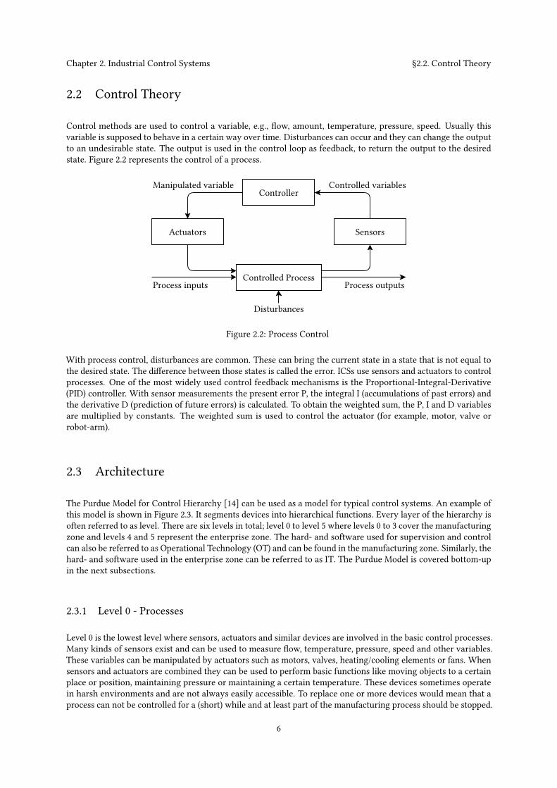
Control methods are used to control a variable, e.g., flow, amount, temperature, pressure, speed. Usually thisvariable is supposed to behave in a certain way over time. Disturbances can occur and they can change the outputto an undesirable state. The output is used in the control loop as feedback, to return the output to the desiredstate. Figure 2.2 represents the control of a process.
Controller
SensorsActuators
Controlled Process
Disturbances
Process inputs Process outputs
Manipulated variable Controlled variables
Figure 2.2: Process Control
With process control, disturbances are common. These can bring the current state in a state that is not equal tothe desired state. The difference between those states is called the error. ICSs use sensors and actuators to controlprocesses. One of the most widely used control feedback mechanisms is the Proportional-Integral-Derivative(PID) controller. With sensor measurements the present error P, the integral I (accumulations of past errors) andthe derivative D (prediction of future errors) is calculated. To obtain the weighted sum, the P, I and D variablesare multiplied by constants. The weighted sum is used to control the actuator (for example, motor, valve orrobot-arm).
2.3 Architecture
The Purdue Model for Control Hierarchy [14] can be used as a model for typical control systems. An example ofthis model is shown in Figure 2.3. It segments devices into hierarchical functions. Every layer of the hierarchy isoften referred to as level. There are six levels in total; level 0 to level 5 where levels 0 to 3 cover the manufacturingzone and levels 4 and 5 represent the enterprise zone. The hard- and software used for supervision and controlcan also be referred to as Operational Technology (OT) and can be found in the manufacturing zone. Similarly, thehard- and software used in the enterprise zone can be referred to as IT. The Purdue Model is covered bottom-upin the next subsections.
2.3.1 Level 0 - Processes
Level 0 is the lowest level where sensors, actuators and similar devices are involved in the basic control processes.Many kinds of sensors exist and can be used to measure flow, temperature, pressure, speed and other variables.These variables can be manipulated by actuators such as motors, valves, heating/cooling elements or fans. Whensensors and actuators are combined they can be used to perform basic functions like moving objects to a certainplace or position, maintaining pressure or maintaining a certain temperature. These devices sometimes operatein harsh environments and are not always easily accessible. To replace one or more devices would mean that aprocess can not be controlled for a (short) while and at least part of the manufacturing process should be stopped.
6

Chapter 2. Industrial Control Systems §2.3. Architecture
HMILevel 2
Level 3
Level 1
Firewall
Firewall
Email, Intranet, etc. Site business planning and logistics network
Enterprise network
Level 4
Level 5
Area Control
Site ControlProductionManagement
Control RoomWorkstations
DataHistorian
WorkstationEngineer
StationOperator
AntivirusServer
PatchManagementMirror
Historian
ApplicationServer
ZoneManufacturing
Zone (DMZ)Demilitarized
Enterprise Zone
PLC RTU IED Basic Control
Level 0 Processes
FlowLightTemperature
PressureSensors
Speed
Position Robot-armLamp/laser
MotorHeat/coolValve
FanActuators
Figure 2.3: ICS architecture. Inspired by CISCO [6] and NIST [16].
2.3.2 Level 1 - Basic Control
This level consists of devices that control level 0 devices using discrete and analog signals. Three devices can befound in this layer; Programmable Logic Controllers (PLCs), Remote Terminal Units (RTUs) and Intelligent Elec-tronic Devices (IEDs). They take the role of the controller shown in Figure 2.2. These devices can be programmedto control processes using multiple sensors and actuators. While their overall features are quite similar, they havedifferences.
The Programmable Logic Controller (PLC) is a microprocessor-based device often used in in SCADA and Dis-tributed Control Systems (DCSs) [6]. It is usually highly configurable; they can be programmed to control acomplex processes using logic, timing, counting and PID control. A PLC can used in a large range of applicationsas a generic solution and therefor the cost is relatively low, compared to a custom-designed component.
The Remote Terminal Unit (RTU), sometimes called a Remote Telemetry Unit, is often used for the purpose ofremote control. It can come equipped with a wireless radio and has extensive communication options. This makesthe RTU useful when a control system covers a large geographical area.
The Intelligent Electronic Device (IED) can perform control and monitor functions and communicate to SCADAsystems with wired or wireless communication. It also includes protection functions, such as voltage regulators,
7
Chapter 2. Industrial Control Systems §2.3. Architecture
circuit breaker controllers, recloser controllers and capacitor bank switches. IEDs can include a HMI, such as adisplay and buttons for supervision and control.
2.3.3 Level 2 - Area Control
Level 2 represents an area within a site or a manufacturing process. The main elements are Distributed ControlServers (DCSs), Human Machine Interfaces (HMIs), operator stations, engineer workstations and switches.
A Distributed Control Server (DCS) can be used to control systems which are deployed at the same location.It supervises and controls level 1 controllers using communication protocols, such as Modbus or Fieldbus overTransmission Control Protocol (TCP). The DCS contains applications for product-, site asset- and performance-management.
The Human Machine Interface (HMI) is an interface for humans and machines to communicate. This is often adisplay or screen and buttons. The HMI is sometimes called a Man Machine Interface (MMI) or Graphical UserInterface (GUI). It can be used to monitor or modify a state or a process. It can also be used to configure controlalgorithms and parameters in controllers. Typically it is used locally for one machine or piece of equipment. TheHMI can also be used to display reports or historical data.
An operator station offers the same functionality as the HMI, but for multiple machines or pieces of equipment.
An engineer workstation is a regular personal computer where an engineer can supervise and control the area ormanufacturing process. The engineering workstation can also be used to (re)program the logic of the PLC’s. APLC should either be connected to the engineering workstation with a programming interface to be programmedor have a SD-card or USB interface to load its new configuration from. A version of Windows is often used as OSfor personal computers.
Switches are used to connect level 1 devices to level 2 and level 2 devices to level 3. The switch can contain afirewall, an Intrusion Detection System (IDS) or Port security. Port security prevents intruders to just physicallyplug a network cable into the network port and connect to the network. This is done by matching the MediaAccess Control (MAC) address of the connecting device with a known MAC address. A match will allow thedevice to connect. The communication link will be disabled if there is no match.
2.3.4 Level 3 - Site Control
This level supervises and controls the whole site. It contains a Data Historian, which is a centralized databasefor logging. A Data Historian logs all process information within an ICS so that the stored information canbe accessed to support various analysis. A control room with engineer workstations, HMIs or other site leveloperation management is used by engineers to supervise and control the whole site. Production ManagementSoftware is used for scheduling and production reporting to manage the productivity of the site.
2.3.5 Level 4 and 5 - Enterprise zone
Levels 4 and 5 are not part of the control system zone. The enterprise zone contains regular IT equipment and isconnected to the Internet. Level 4 is used for site business planning and logistics. Level 5 can contain all regularbusiness activities. While important, these systems are not critical to the control system zone.
2.3.6 Demilitarized zone (DMZ)
The Demilitarized zone (DMZ) acts as a divisor between enterprise environment and the manufacturing envi-ronment so that data can be shared. It can segment control of the enterprise environment and manufacturingenvironment. No traffic should pass the DMZ directly, but should always travel through it. Firewalls should beconfigured to enforce this. The DMZ adds another layer of security. For example, the historian mirror in theDMZ synchronizes at an interval with the historian in level 3. If a level 4 or 5 application needs information from
8
Chapter 2. Industrial Control Systems §2.4. Comparison of ICS and IT
the historian it can now connect to the historian mirror in the DMZ. There is no longer a need to connect to theManufacturing zone. This reduces the number of connections from the Enterprise zone to the Manufacturingzone.
2.4 Comparison of ICS and IT
As stated in Section 2.1 ‘History’, ICS are resembling IT systems more than before. They have their similarities butalso their differences. One of the biggest differences is that ICSs directly affect the physical world with actuatorsto, for instance, produce a product or provide a service. If the control system is not able to produce a product orprovide a service, it will likely result in immediate financial loss or other damages. Availability is therefor oftenseen as the most important aspect. Another important aspect for ICSs is safety in the sense of physical safety andequipment safety. The loss of integrity could mean that a controller would control a process in an undesirableway and lead to production losses, loss of equipment, endangerment of human safety or environmental damages.
In Table 2.1 several key-differences between IT systems and ICS are pointed out. An important item to note ischange management. The availability and integrity requirements make ICSs hard to patch. Many ICSs are notoften patched or not patched at all [18]. Since components can have a lifetime up to 15-20 years, it is possible tofind old unpatched systems. This creates a big contrast to IT systems where new equipment is bought every fewyears and (security) patches are often automatically installed. Old and unpatched systems may contain knownvulnerabilities that can be exploited by malware.
9

Chapter 2. Industrial Control Systems §2.4. Comparison of ICS and IT
Category Information Technology System Industrial Control System
Risk ManagementRequirements
Data confidentiality and integrity isparamount
Fault tolerance is less important -momentary downtime is not a major risk
Major risk impact is delay of businessoperations
Human safety is paramount, followed byprotection of the process
Fault tolerance is essential, even momentarydowntime may not be acceptable
Major risk impacts are regulatorynon-compliance, environmental impacts,loss of life, equipment, or production
Architecture SecurityFocus
Primary focus is protecting the IT assets,and the information stored on or transmittedamong these assets. Central server mayrequire more protection
Primary goal is to protect edge clients (e.g.,field devices such as process controllers)Protection of central server is also important
UnintendedConsequences
Security solutions are designed aroundtypical IT systems
Security tools must be tested (e.g., off-line ona comparable ICS) to ensure that they do notcompromise normal ICS operation
Time-critical Interaction Less critical emergency interaction
Tightly restricted access control can beimplemented to the degree necessary forsecurity
Response to human and other emergencyinteraction is critical
Access to ICS should be strictly controlled,but should not hamper or interfere withhuman-machine interaction
System Operation Systems are designed for use with typicaloperating systems
Upgrades are straightforward with theavailability of automated deployment tools
Differing and possibly proprietary operatingsystems, often without security capabilitiesbuilt in
Software changes must be carefully made,usually by software vendors, because of thespecialized control algorithms and perhapsmodified hardware and software involved
Communications Standard communications protocols
Primarily wired networks with somelocalized wireless capabilities
Typical IT networking practices
Many proprietary and standardcommunication protocols
Several types of communications media usedincluding dedicated wire and wireless (radioand satellite)
Networks are complex and sometimesrequire the expertise of control engineers
Resource Constraints Systems are specified with enough resourcesto support the addition of third-partyapplications such as security solutions
Systems are designed to support theintended industrial process and may nothave enough memory and computingresources to support the addition of securitycapabilities
Change Management Software changes are applied in a timelyfashion in the presence of good securitypolicy and procedures. The procedures areoften automated
Software changes must be thoroughly testedand deployed incrementally throughout asystem to ensure that the integrity of thecontrol system is maintained. ICS outagesoften must be planned and scheduleddays/weeks in advance. ICS may use OSsthat are no longer supported
Component Lifetime Lifetime in the order of 3-5 years Lifetime in the order of 15-20 years
Access to Components Components are usually local and easy toaccess
Components can be isolated, remote, andrequire extensive physical effort to gainaccess to them
Table 2.1: Differences between IT and ICS. Obtained from NIST Special Publication [16].
10

ChapterExperimental environment3
This chapter describes the environment andmalware used in the tests. A simulated environment was used becausethe developed malware will try to impact availability and integrity, the properties that are most important toICSs. It is not feasible to test malware on a real working ICS. The scenario, set-up and the components of theenvironment will be discussed here.
A literature study on ICS simulation testbeds was performed. Several testbeds were found, such as the onedescribed by Béla Genge et al. [13] based on Emulab to create cyber components and Simulink to create physicalprocesses. The testbed is used to measure the impact of attacks against the cyber and physical parts of the system.Another testbed described by Fovino et al. [10] uses an experimental test-bed, deployed in Italy, to simulate attackscenarios against SCADA systems. The experimental testbed contains a physical power plant emulator withreal PLCs and sensors. Reaves et al. propose a virtual testbed for industrial security research [23] build using anetwork simulator called ‘ns-2’.
The purpose of this research is to research the knowledge needed to develop malware to infect and impactan Industrial Control System. For that we need to measure the effect of a change in the environment on themalware and be able to determine if the malware can adapt to different environments. We need an experimentalenvironment that can be changed and adapted according to the changes we would like to make in the environment.We also need real ICS software for the malware to exploit.
The testbed described by Béla Genge et al. [13] is not very suitable because Emulab has disabled several Windowsfacilities/services (e.g., firewall) that we plan to use as one of our change in the environment. While all Windows7 changes are documented, this is not the case for the Windows XP changes 1. The testbed described by Fovinoet al. [10] can not be used because setting up a real physical testlab with PLCs, sensors and actuators is outsideof the scope. The testbed proposed by Reaves et al. [23] is not suitable because it does not provide full supportfor the TCP protocol (e.g. no RESET segments) 2. We can obtain unreliable results if any of the unimplementedTCP functionality is used by the HMI or malware to communicate with the PLC during our tests.
We looked at existing ICS testbeds but we can also consider other ICS software and simulators that are available.We chose this approach because it provides a fast way to start the project and is available for free. The HMIsoftware provided a graphical demo project that we use to get started. We extend the setup according to ourneeds and described it in the following sections.
3.1 Scenario
The experimental environment will represent a part of the chemical plant which mixes and stores chemicals inlarge tanks. The tanks are connected by pipes and pumps are used to pump chemicals from one tank to another.The first tank has an entry point with a valve to add chemicals while another tank has an exit point with a valvefor chemicals to flow to the next process. This is shown in picture 3.1. The chemicals should be in exactly theright ratio before they leave the final tank. An ICS is used to control the processes using sensors and actuators.Sensors read the chemical levels in the tanks while the actuators control the state of the valves and pumps. APLC is able to communicate with the sensors and actuators as well as with other systems. The PLC containsprogrammable logic to perform basic control of the mixing process.
Engineers can supervise and control these processes using a HMI which queries the PLC for sensor values andgraphically displays it a screen. The software also enables engineers to control the actuators through the PLC. It
1https://wiki.emulab.net/wiki/Emulab/wiki/Windows2http://www.isi.edu/nsnam/ns/ns-limitations.html
11
Chapter 3. Experimental environment §3.1. Scenario
Figure 3.1: Overview chemical plant HMI
is important to note that software influences the physical world using actuators. Supervision and management isdone at the plant in a control room.
One day an employee wants to supervise the plant from home using his work-laptop. At the plant he sets up aremote desktop service and configures his laptop to connect to the service. Consider the case where the employeegoes home and his laptop gets infected with malware. When the employee uses his credentials to log-in to theremote desktop service the malware records his credentials. With these credentials malware can also log in andspread to the plant.
Malware can also spread to the plant in other ways. USB sticks or other USB devices are being used to transportconfiguration files of the logic of the PLC. Another way to spread would be to infect a USB stick with these fileson it. The malware will spread once the USB stick is inserted in a machine in the plant. These infection paths areshown in Figure 3.2.
1.
2. 3.
Chemical plantOperational Technology
1. Infected USB device2. Infected USB device, network share or physical movement of laptop3. Infected USB device or HMI software exploit
Employeelaptop
HMI
Attacker
PC PLC
1.
Figure 3.2: Infection path
Inside the plant malware spreads to a machine where it can communicate with the PLC and intercept traffic
12

Chapter 3. Experimental environment §3.2. Components
between the HMI and the PLC. It can tell the PLC to manipulate valves and pumps to mix the chemicals in anundesirable way or overflow a tank with chemicals while telling the control software that everything is normal.This way malware can influence the physical world and create production losses, environmental damages or evenpotentially affect human safety.
3.2 Components
The mentioned scenario is recreated in a virtual environment where every component is running in its ownVirtual Machine (VM). The VMs are run with VirtualBox 3. A virtual network is made between the machinesaccording to Figure 3.2. The ‘Employee laptop’ and ‘PC’ described in Figure 3.2 will run Windows 7 SP0. Anolder version of Windows is used for the OT part of the plant because software updates are not often updatedor patched or not patched at all [18]. Windows XP SP3 is used for the VMs in the OT part of the plant. Thecomponents described in this section are used to represent the described scenario.
3.2.1 HMI software
Interactive Graphical SCADA System (IGSS) version 9 is used 4 to supervise and control the environment. IGSSis developed by 7-Technologies (7T). 7-Technologies has been acquired by Schneider Electric in August 2011. Anewer version of IGSS, version 10 is released in September 2012. This version is most likely not adopted everyonebecause of the slow rate of which updates are planned for ICSs as mentioned in Section 2.4. IGSS provides: atool to design HMIs which in turn can be used to supervise and control a SCADA system; support for manycommunication protocols; and functionality to set preventive maintenance jobs. Warnings and alarms are definedin the HMI designer. A graphical effect or other actions are configured on a warning or alarm. It is also possibleto generate rapports and monitor communications.
Configuration
The HMI software that represents the scenario is shown in Figure 3.1. The case where all drums are overflowingis shown in Figure 3.3. In the figure we can see that the level indicators on each drum indicate a full drum. On theright we see the number of chemical units that have overflowed. Also note the orange square in the right lowercorner. This object is linked to the alarm module of the HMI. The alarm module shows all errors and warnings.The square’s color shows the type of error or warning and the number indicates the amount.
As visible in figures 3.1 and 3.3, each drum has two indicators which indicate the chemical level: A bar placed onthe drum and an additional pie indicator. It is possible to configure warnings and alarms for each drum. Everydrum is set to give a warning when it is almost empty or almost full. The almost empty warnings are configuredwhen the drum reaches a chemical level of 5 units or below and the almost warning is configured when the drumcan only store less than 10 units more. The pie indicator marks those areas with red. In Figure 3.3 all drums arefull, i.e., the chemical level reaches 100 units. A full drum is not desirable because any addition of chemicals willresult in an overflow. An alarm is configured to fire during this condition. It is also possible to set an ‘animatedsymbol’ during warnings or alarms. This way it is possible to show, hide, blink or change the color of an existingelement. An animated symbol is used to create an ‘overflow animation’ which is linked to the ‘drum is full’ alarm.We’ve used this to create the overflow animation.
Vulnerabilities
ICS environments are often equipped with old and unpatched systems and software as revealed in survey [18]and discussed in Section 2.4. This opens the possibility for attackers to use existing exploits to target ICSs.
3http://www.virtualbox.org/4http://igss.schneider-electric.com/products/igss/
13
Chapter 3. Experimental environment §3.2. Components
Figure 3.3: HMI representation of the chemical plant with drums overflowing.
IGSS version 9 has several remote vulnerabilities. It is possible to infect the HMI by exploiting two of these remotevulnerabilities.
The first service IGSSdataServer runs on port 12401 and is responsible for the synchronization of data, includingthe HMI description, between the IGSS server and the operator stations. This functionality is also used whena setup is created with a primary and a secondary hot-backup server. The graphical HMI description is storedin several files. The service synchronizes the HMI description files with remote read, create, write, rename anddelete commands. With a directory traversal attack it is possible to perform those actions for any file on thesystem 5. The protocol used by the service is TCP/Internet Protocol (IP) with a proprietary application levelprotocol.
Another vulnerability is the directory traversal vulnerability in the Data Collector dc.exe which can be accessedfrom port 12397. The service collects and calculates the data which is shown on the HMI. It also contains an EXEopcode to run an executable with a CreateProcessA() function as a new thread. Arguments can be given but areoptional. This functionality is not protected against directory traversal attacks. By exploiting this vulnerabilityany file can be executed on the remote host 6. TCP/IP with a proprietary application level protocol is used.
All versions ≤ 9.00 of IGSSdataServer and versions ≤ 9.00 of dc.exe are vulnerable. The exploit details state thatthey are tested with IGSS versions 9 and lower that run on Windows XP, Windows 7 and Windows Server 2003 /R2. Service packs do not have any influence on the exploit.
3.2.2 Programmable Logic Controller (PLC)
The PLC is simulated using a Modbus PLC simulator program called Mod_RSsim 7. A running instance is shownin Figure 3.4. The simulator shows coil outputs, digital and analogue inputs and registers that can be writtento or read from. These are shown in a table with 10 addresses per row and the values can be shown in decimal,hexadecimal, as a float or character string. The PLC simulator supports multiple connections and is able tocommunicate using Modbus/RS-232, Modbus/TCP and DF1 (configured as an Allen Bradley Slave or a simplemaster that simulates a JOY SCC386). A communication monitor can show all send and received messages.
The values of the coils and registers can be manipulated by the PLC simulator to simulate a physical environment.5CVE-2011-15656CVE-2011-15667http://www.plcsimulator.org/
14

Chapter 3. Experimental environment §3.3. Physical processes
Figure 3.4: Mod_RSsim - PLC simulator
The PLC simulator can be automated with a Visual Basic script that is executed every 500ms. Some functionshave been provided for the script to interact with the simulator. For instance the functions GetRegisterValueand SetRegisterValue can be used by the VBscript to read register states from the PLC and write register valuesback. We use this functionality to simulate the physical processes of the chemical plant. The physical processesdescribed in Section 3.1 are simulated with a Visual Basic script and described in the next subsection.
3.3 Physical processes
This subsection will explain the physical processes of the chemical plant example that is used throughout ourexperiments. The in Section 3.1 described part of the chemical plant contains four drums and four pumps topump chemicals from one drum to another in a clockwise fashion. A valve regulates the addition of chemicals todrum 1 and another valve regulates the amount of chemicals that leave the process through drum 2. This processis shown in Figure 3.5.
Pump 2
Pump 3
In-valveOut-valve Pump 1
Pump 4
Drum 2
Drum 3 Drum 4
Drum 1
Figure 3.5: Overview chemical plant
The amount of chemicals a drums is able to contain ranges from 0 to 100 units where 0 is completely empty and100 means full. If chemicals flow to a full drum, it will result in an overflow. An undesired state or ‘critical state’is reached when the drums are completely empty or overflowing. The amount of spilled chemicals is recorded
15
Chapter 3. Experimental environment §3.4. Malware
and shown on the HMI. The actuators are simulated once every time the script is executed. Pumps have threesettings: ‘On’, ‘Off’ and ‘Automatic’. The setting ‘On’ will pump chemicals with a speed of 2 units per scriptexecution to the next drum. When the pump is set to ‘Off’ it will not do anything. The setting ‘Automatic’ onlypumps chemicals to the next drum when the chemical level of the current drum is higher than 80 and the nextdrum has a lower chemical level than the current drum. Valves have two settings: ‘open’ and ‘close’. When avalve is open it will enable a chemical flow with a speed of 1 unit per script execution. These physical processeswill be simulated by the Visual Basic script and can be found in Appendix D.
The default physical environment state is the following; both in- and out-valves are closed, drum 1 has a chemicallevel of 55, drum 2 has a chemical level of 60, drum 3 has a chemical level of 70 and drum 4 has a chemical levelof 45. Pumps 1 and 3 are set to ‘auto’ and pumps 2 and 4 are off. This state has been chosen because it is a stablestate; nothing changes. This way, it is possible to get repeatable results since the time between resetting thedefault physical environment state and the execution of the malware is not important.
The described environment will be referenced from now as the ‘default environment’ or ‘clean environment’. Wewrite malware that is able to infect and impact this setup according to the specifications described in the nextsection.
3.4 Malware
This section covers different existing IT and ICSmalware and describes the intentions and structure of themalwarethat is developed for this environment.
3.4.1 ICS targeted malware
Stuxnet was different from other malware as it directly targeted Operational Technology. Stuxnet is a computerworm type ofmalware that targeted Iran’s uranium enrichment facilities to sabotage the ICSs [9]. It was discoveredin June 2010 and believed to be created by the U.S. and Israel [24] to stop or at least delay Iran’s nuclear program.Stuxnet includes a few known exploits, four zero-day exploits, the first ever PLC rootkit, a Windows rootkit,peer-to-peer updates, a command and control center and other functionalities [9]. The uranium enrichmentfacility’s centrifuges were targeted by reprogramming the PLCs to repeatedly adjust the spinning speed to veryslow and faster than normal [9]. This process will make it look like the centrifuge broken down because thecentrifuge was of low quality. Stuxnet destroyed more than a thousand centrifuges.
3.4.2 IT targeted malware
The following malware have not directly targeted the OT part of the ICS but mainly targeted the IT part or wereused for espionage.
Duqu’s main purpose is to gather information and assets from entities such as industrial infrastructure and systemmanufacturers. This is to obtain information such as design documents to more easily perform future attacks.Duqu is found in September 2011. It is a Remote Access Trojan and it does not contain code to replicate itself orany code related to ICSs. Duqu was written by the same authors as Stuxnet (or those with access to the code)[28].
Flame, also known as Flamer and sKyWIper, is a modular malware used for targeted cyber espionage in MiddleEastern countries. It can record audio, screenshots, keystrokes, network traffic and Skype conversations [8].Flame uses five encryption methods and SQLite to store structured information [7]. To reduce the probability ofdetection it also determines what antivirus software is installed to customise its own behavior. The in May 2012discovered Flame is very large for a malicious program: it is 20 megabytes large. It allows other attack modulesto be loaded after infection. The source code of at least one module of Flame was used in Stuxnet. This provesthat the Stuxnet and Flame developers have cooperated at least once during early development [15].
Night Dragon is a coordinated covert and targeted cyberattacks against global oil, energy and petrochemicalcompanies that has been conducted since November 2009 [26]. Night Dragon is a Trojan backdoor with the
16
Chapter 3. Experimental environment §3.4. Malware
goal to obtain sensitive competitive proprietary operations and financial information. These attacks primarilyoriginated from China and involved social engineering, exploitation of Windows OS vulnerabilities, MicrosoftActive Directory Compromises and the use of remote administration tools [26].
Shamoon (Disttrack) is a modular computer virus that attacks Windows OSs and is used for cyber-sabotage in theenergy sector. Shamoon is build up out of three components: a Dropper, which is the main component and sourceof the infection; a Reporter, which reports infection information back to the attacker; and a Wiper that corruptsfiles on an infected machine and overwrites the Master Boot Record. The wiper component is responsible for thedestructive functionality; it replaces an existing driver with another digitally signed driver that enables user-modeapplications to read and write to disk [1].
3.4.3 Custom ICS tailored malware
With all those different malware out there, we can ask ourselves: ‘Why not reuse Stuxnet to answer the researchquestion?’. It is possible to download the reverse engineered Stuxnet source code. At first it seems like a goodidea, because it saves time. On the other hand, we need to familiarize ourselves with the reverse engineeredStuxnet code. The code is not well documented and while most functions have understandable names, mostvariable names are not representative; they are a combination of a letter and a number. We need to know the codewell enough it we want to modify it. This takes considerable time. Another counterargument is that Stuxnet wasprogrammed to target one type of plant and will not activate unless it detects that it has reached its target. Torecreate that plant might also take a long time. In the end it will likely take less time to develop malware ourselves.This way we can implement the functionality we need and we have more freedom to choose and modify ourenvironment.
We will develop malware and test if it still spread and affect the integrity and availability of the ICS when theexperimental environment changes. The malware’s goal is to spread to the chemical plant and create a securityimpact at the plant. When the malware infects a regular IT system it will not try to impact the system, since itis not the goal of the malware. This action would do more harm than good as it increase the chance of gettingdetected. Initially the malware only scans for other systems and spread. Only once the malware detects that itreached its target, it will try to create an impact on the security of the plant. This strategy is programmed intoour malware. The malware’s architecture is shown in Figure 3.6.
Strategy
BufferIO FileIO NetwIO & WinpcapIO WindowsIO
IT generic payloads ICS specific payloads
Modbus
Figure 3.6: Malware architecture
The malware works according to the scenario described in Section 3.1 and infection path shown in Figure 3.2.An attack graph is given in Figure 3.7 and described here. The initial infection can be caused by a targetedattack. The attacker will either infect a USB device or an attachment and target a plant employee or someonerelated. When an infected USB device is used as attack vector, it can be left in front of the home or car of a plantemployee or be given to a family member. When the USB stick is plugged in a computer it will automatically
17
Chapter 3. Experimental environment §3.4. Malware
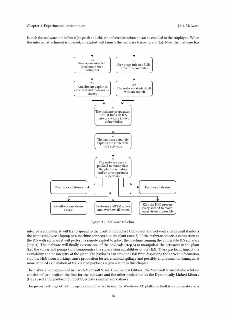
launch the malware and infect it (steps 1b and 2b). An infected attachment can be emailed to the employee. Whenthe infected attachment is opened, an exploit will launch the malware (steps 1a and 2a). Now the malware has
1.aUser opens infectedattachment on a
computer
1.bUser plugs infected USB
drive in a computer
Overflows all drums Empties all drums
Overflows one druma.s.a.p.
Performs a MITM attackand overflow all drums
Kills the HMI processevery second to makesupervision impossible
a.
3.The malware propagates
until it finds an ICSnetwork with a known
vulnerability
2.bThe malware starts itself
with an exploit
2.aAttachment exploit is
executed and malware isstarted
4.The malware remotelyexploits the vulnerable
ICS software
c. d.
b.
e.
5.The malware uses apayload to manipulatethe plant’s actuatorsand/or to compromise
supervision
Figure 3.7: Malware timeline
infected a computer, it will try to spread to the plant. It will infect USB drives and network shares until it infectsthe plant-employee’s laptop or a machine connected to the plant (step 3). If the malware detects a connection tothe ICS with software it will perform a remote exploit to infect the machine running the vulnerable ICS software(step 4). The malware will finally execute one of the payloads (step 5) to manipulate the actuators in the plant(i.e., the valves and pumps) and compromise the supervision capabilities of the HMI. These payloads impact theavailability and/or integrity of the plant. The payloads can stop the HMI from displaying the correct information,stop the HMI from working, cause production losses, chemical spillage and possibly environmental damages. Amore detailed explanation of the created payloads is given later in this chapter.
Themalware is programmed in CwithMicrosoft Visual C++ Express Edition. TheMicrosoft Visual Studio solutionconsists of two project; the first for the malware and the other project builds the Dynamically Linked Library(DLL) used a the payload to infect USB drives and network shares.
The project settings of both projects should be set to use the Windows XP platform toolkit so our malware is
18
Chapter 3. Experimental environment §3.4. Malware
compatible with Windows XP. The runtime library setting should be set from ‘Multi-threaded DLL’ to ‘Multi-threaded’ so that most libraries (DLLs) will be included in the executable. This will make our malware lessdependent on the other system’s libraries. During the development phase we have tested basic changes on the‘Employee laptop’ and the ‘PC’ as defined in Section 3.1. These changes include; removing admin privileges,changing OS version, changing network interface configurations and changing IP addresses. This was mainlydone to iron out bugs but also to asses the malware’s stability.
Design decisions
Arguably the biggest design choice had to be made during the implementation of the Man-in-the-Middle (MITM)attack. During our attack we would like to let the HMI believe that all systems work as normal. This is done byperforming a MITM attack; we send traffic to the HMI and make it look like it came from the PLC and vice versa.When performing a MITM attack, we need to forge (spoof) packets. This makes the target believe a packet isoriginated from a specific machine. Since we want to spoof Modbus/TCP traffic, we need to spoof TCP and IPfields. These spoofed packets should contain the source IP address of another machine and we also need to setother TCP and IP fields. This information is usually filled in automatically when a network socket is created andit can not be changed. To set these fields we need a raw socket. If we have a raw socket we can manipulate allfields of the packet.
C does not support raw sockets for TCP connections 8. This means that there is no easy way of spoofing TCPtraffic. It is possible to implement custom network sockets (in Assembly or if possible in C) but this would takequite some time and research. Another option was to use the tool ‘winpcap’ 9. Winpcap is a link-layer networkaccess for Windows environments, it allows applications to capture and transmit network packets bypassing theprotocol stack. It is used as capture and filtering engine of many known network tools. Winpcap can be used tochange any packet field necessary. We decided to use the winpcap functionality for spoofing packets because adetermined attacker will likely be able to spoof packets. A determined attacker can create the functionality tosend raw packets over the network, embed the winpcap installer into the malware or create the same functionalityas winpcap provides.
Another design decision was whether to use a scanner or not. Currently our malware uses one remote exploit.It is possible to run the exploit on every IP address in the subnet’s range. This would require quite some timesince the timeout of every connection is set to 30 seconds. A scanner would enable solution that is faster andmore scalable with the number of exploits. The method we’re looking for should be fairly accurate, preferablyfast and simple. We will therefor not scan every port of every machine but just one port per machine. A simpleping sweep would do the job here as it meets all requirements. We have used a simple ping scan to detect allmachines in the network.
The malware is supposed to execute its final payload only when it has reached the plant. The malware determinesif it reached the plant by checking if the infected machine had HMI software (IGSS) installed. This means thatthe malware could also have triggered on nontargets that used the same HMI software.
Payloads
Eight payloads were developed, two to infect the plant and six more to create an impact on the security of theplant.
PAY-1. The first payload is used to infect USB devices and shared folders. It uses the same vulnerability 10 in theWindows’ explorer program as Stuxnet did. When explorer shows a folder to the user, it will load thefiles and, if visible, their icons. A shortcut file (.lnk) is a Windows shortcut to another file. It will usuallydisplay the icon of the file it links to, but their icon can be changed more dynamically than any other filetype. When a specially crafted icon of a shortcut is shown, an arbitrary library (DLL) can be specified tobe loaded and executed.
8http://msdn.microsoft.com/en-us/library/windows/desktop/ms740548(v=vs.85).aspx9http://www.winpcap.org/10The ‘ms10_046 shortcut icon DLL loader’ vulnerability
19
Chapter 3. Experimental environment §3.4. Malware
A library was developed to find and execute our malware. This library will be seen as part of the malware.When the malware infects a shared medium, it will copy itself to the shared medium and create an infectedshortcut. The shortcut’s icon references to the malware (library part). In short; when a folder with theinfected shortcut is shown, part of our malware will be loaded and executed. The malware will run as partof the exploited explorer process with the same rights. Our malware infects USB devices and networkshares with shortcut files and it also copies itself there. This payload is used to infect USB devices andnetwork shares in step 1b, 2b and 3 of Figure 3.7. This exploit will later be referenced as the ‘shortcutexploit’ or ‘shortcut vulnerability’.
PAY-2. This payload is used to infect the HMI in the environment. It exploits the remote vulnerabilities in theIGSS services mentioned in Section 3.2.1. The IGSS data server service contains a directory traversalvulnerability which can be used to perform file operations. The data collector service has a directorytraversal vulnerability which can be exploited to run any executable present on the remote machine. Thesevulnerabilities are remotely exploited by the malware to copy and execute itself on the target machine.This payload is used in step 4 of Figure 3.7.
PAY-3. The payload’s goal is to put the system in a critical state; it will overflow all drums. It impacts the integrityof the plant by manipulating actuators. The payload sends Modbus/TCP commands to the PLC to openthe ‘in-valve’, close the ‘out-valve’ and set the pumps to automatic. The drums will gradually fill andeventually overflow. No MITM attack is performed so the HMI will show the real state of the controlsystem during the attack. The harmful state is written to the PLC periodically (e.g., every second) or everytime an engineer manipulates the state of the pumps or valves.
PAY-4. The previous payload can be modified to empty all drums. This payload is a copied version of payloadPAY-3 with the exception that it empties all drums.
PAY-5. To create impact as quickly as possible, a payload can be used that only overflows the fullest drum. Thispayload checks the chemical levels in each drum and overflows only the fullest drum by manipulatingthe pumps and valves.
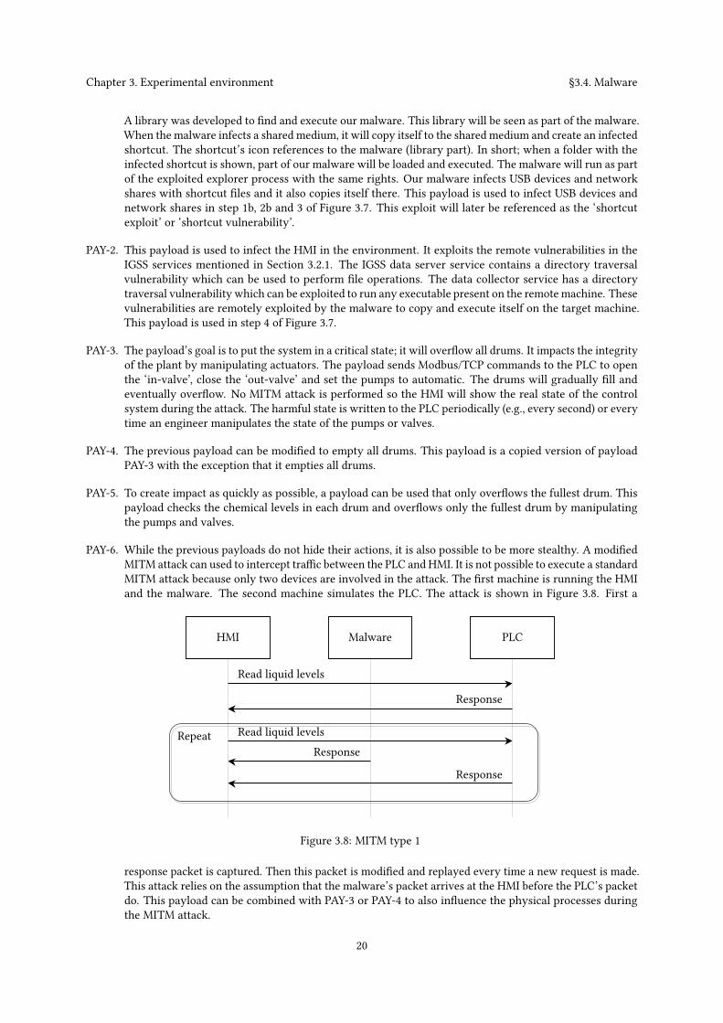
PAY-6. While the previous payloads do not hide their actions, it is also possible to be more stealthy. A modifiedMITM attack can used to intercept traffic between the PLC and HMI. It is not possible to execute a standardMITM attack because only two devices are involved in the attack. The first machine is running the HMIand the malware. The second machine simulates the PLC. The attack is shown in Figure 3.8. First a
HMI Malware PLC
Read liquid levels
Response
Read liquid levelsResponse
Response
Repeat
Figure 3.8: MITM type 1
response packet is captured. Then this packet is modified and replayed every time a new request is made.This attack relies on the assumption that the malware’s packet arrives at the HMI before the PLC’s packetdo. This payload can be combined with PAY-3 or PAY-4 to also influence the physical processes duringthe MITM attack.
20
Chapter 3. Experimental environment §3.4. Malware
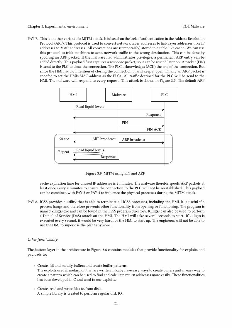
PAY-7. This is another variant of aMITM attack. It is based on the lack of authentication in the Address ResolutionProtocol (ARP). This protocol is used to convert network layer addresses to link layer addresses, like IPaddresses to MAC addresses. All conversions are (temporarily) stored in a table-like cache. We can usethis protocol to trick machines to send network traffic to the wrong destination. This can be done byspoofing an ARP packet. If the malware had administrator privileges, a permanent ARP entry can beadded directly. This payload first captures a response packet, so it can be resend later on. A packet (FIN)is send to the PLC to close the connection. The PLC acknowledges (ACK) the end of the connection. Butsince the HMI had no intention of closing the connection, it will keep it open. Finally an ARP packet isspoofed to set the HMIs MAC address as the PLCs. All traffic destined for the PLC will be send to theHMI. The malware will respond to every request. This attack is shown in Figure 3.9. The default ARP
HMI Malware PLC
Read liquid levels
Response
Read liquid levelsResponse
Repeat
FIN
FIN ACK
ARP broadcastARP broadcast90 sec
Figure 3.9: MITM using FIN and ARP
cache expiration time for unused IP addresses is 2 minutes. The malware therefor spoofs ARP packets atleast once every 2 minutes to ensure the connection to the PLC will not be reestablished. This payloadcan be combined with PAY-3 or PAY-4 to influence the physical processes during the MITM attack.
PAY-8. IGSS provides a utility that is able to terminate all IGSS processes, including the HMI. It is useful if aprocess hangs and therefore prevents other functionality from opening or functioning. The program isnamed killigss.exe and can be found in the IGSS program directory. Killigss can also be used to performa Denial of Service (DoS) attack on the HMI. The HMI will take several seconds to start. If killigss isexecuted every second, it would be very hard for the HMI to start up. The engineers will not be able touse the HMI to supervise the plant anymore.
Other functionality
The bottom layer in the architecture in Figure 3.6 contains modules that provide functionality for exploits andpayloads to;
• Create, fill and modify buffers and create buffer patterns.The exploits used in metasploit that are written in Ruby have easy ways to create buffers and an easy way tocreate a pattern which can be used to find and calculate return addresses more easily. These functionalitieshas been developed in C and used to our exploits.
• Create, read and write files to/from disk.A simple library is created to perform regular disk IO.
21
Chapter 3. Experimental environment §3.4. Malware
• Connect and communicate with a Modbus/TCP device.Libmodbus 11 is integrated into the malware to provide this functionality.
• We can make regular network connectionsRegular network connections are used to scan the local network for machines and to determine if specificports, used by vulnerable services, are open.
• Sniff and spoof traffic.The winpcap library is used to sniff traffic and send raw TCP packets. A layer on top of that provides thefunctionality to interpret the raw traffic, modify and spoof it.
• Obtain information about the current machine.We can obtain information such as the name and IP address of the system, current logged in user, if thecurrent user has admin rights and we can read from and write to registers.
In the next chapter we obtain results according to the methodology described there.
11http://libmodbus.org/
22
ChapterResults4
Now that the environment is setup and the malware is implemented, it is possible to understand what knowledgeis needed to develop malware for the environment. In this chapter two types of results are described: the firstresult describes how the malware infects and impacts the security of the environment. This environment is calledthe ‘default environment’ or the ‘clean environment’. Secondly we will change the environment and determineif the malware is still able to infect and impact the security of the environment. The process of changing theenvironment will be called an ‘environmental change’.
If an environmental change reduces or diminishes the effect of the malware, it does not immediately imply thatthe developer lacked system knowledge. The developer might have made a design decision that another developerwould have made differently. Some design decisions do not support certain changes in the environment. Thosedesign decisions will be revised to mature the malware without introducing new system knowledge. For instance,when the malware was first developed, it scanned the network for vulnerable machines with a ping scan. Theping scan was blocked when firewalls were enabled. The design decision was revised by implementing an ARPscanner. Sometimes the malware can not adapt to the changing environment, not because it was due to a designdecision, but because the developer lacked system knowledge. For example, the malware developer needs toknow what communication protocol is used between the HMI and PLCs. If the malware does not support theprotocol that is used, it might not be able to impact the integrity of the processes. This means that sometimesmultiple attempts are required to determine if an environmental change can reduce or diminish the effect of themalware. Those ‘attempts’ are called ‘tests’. The first test will determine the effect of the environmental changeon the malware. If the malware fails to successfully execute a payload we either modify the malware and performanother test or we determine that system knowledge is needed. If a test succeeds, we can test other variations ordecide to stop.
The rest of the chapter is structured as follows: First, the methodology for obtaining the results is defined. Thena description on how the malware infects and impacts the security of the default environment is given. Lastly wediscuss if the malware was still able to infect and impact the security of the environment after an environmentalchange. These results will help answer the research questions in the next chapter ‘Analysis’.
4.1 Methodology
To get reliable and repeatable results, we need a methodology to perform environmental changes. The methodol-ogy includes: 1) allowed user-interaction; 2) what is monitored and 3) which payloads are used. The methodologywill be linked to the previously defined scenarios in sections 3.1 and 3.4 to show these steps are conform.
The method to test the impact of the payloads on the clean and changed environment is explained here.
1. For each test we start with a clean environment because a well defined starting point will enable us to haverepeatable results. We also do not want malware from the previous test to interfere with the new test.
2. We implement an environmental change before our first test. This step will not be performed when we testthe impact of the malware on the clean environment. For every next test we either change the environmentor change the malware without introducing new system-knowledge in the malware.
3. When we initiate a test we perform limited user-interaction; we only run the malware. The tests areaccording to the infection path defined in Section 3.1, Figure 3.2 and the malware timeline mentioned inSection 3.4.3, Figure 3.7. The step where the malware is manually executed simulates the opening of theinfected attachment in scenario 1a and 2a in Figure 3.7. The step where the USB drive is used representsscenario 1b and 2b in Figure 3.7. To start the malware we:
23
Chapter 4. Results §4.2. Default environment
a. execute the malware once from command line or by double click orb. insert a USB drive. If autoplay is not configured, navigate with explorer to the root of the drive.
No further user-interaction with the system is performed after one of the scenarios is initiated.
4. The systems is monitored according to how the malware is supposed to behave.
(a) If the USB drive is used as an infection medium we check if the malware launches using the shortcutexploit. If the malware launches, payload PAY-1 is successful.
(b) We check if the malware executes the remote exploit (PAY-2) to propagate to the HMI.(c) We check if the malware infects the HMI. If the malware starts, payload PAY-2 has executed success-
fully.(d) The malware is supposed to choose and execute one of its payloads.
• If the malware terminated the HMI process, payload PAY-8 has executed successfully.• The malware should able to modify the PLC address(es) used by the actuator(s). Payloads PAY-3,PAY-4 and PAY-5 are successful if the state of at least one actuator is changed.
• Payloads PAY-6 and PAY-7 execute successfully if the HMI displays the PLC state that spoofedby the malware (and the response from the PLC is discarded or no response from the PLC isreceived).
The results of these tests can be found in Section 4.2.
When we determine if an environmental changes reduced or diminishes the impact of the malware we performthe steps mentioned above. We execute step 2 to change the environment before we test the effect of the malware.For some environmental changes we felt the need to perform multiple tests. For some environmental changeswe needed to perform up to four tests to learn the effect of the environmental change on the malware. For everyadditional test we either modified the environment or malware and the changes were documented. If the malwarecould not (completely) adapt it often meant new system knowledge was needed. We noted if the malware did notbehave exactly as in the clean environment.
Several payloads are considered successful under the same conditions. Therefor we will not test all payloadswhen we test the effect of the environmental changes. For every environmental change we check if the malware;
1. can spread using both infection methods; with the HMI exploit (PAY-2) and the USB exploit (PAY-1);
2. can modify the state of the actuators (PAY-3);
3. is able to perform a MITM attack (PAY-7) and
4. can terminate the process of the HMI repeatedly (PAY-8).
For some environmental changes we felt the need to test more or all payloads. We have noted which additionalpayloads are tested. This way we can reduce a big amount of tests in a way that will not influence our results.
Now that we have defined our tests, we can start performing them.
4.2 Default environment
Eight payloads were developed to infect and impact the security of the system. The effect of the execution ofeach payloads will be discussed here.
RESULT-1. Payload PAY-2 scans for USB drives and network shares and infects them with crafted shortcuts. Theexploit is triggered if a user views the contents of the infected folder and the malware is executed.When an infected folder is accessed through command line it will not trigger the exploit since nographical information is processed.
24

Chapter 4. Results §4.2. Default environment
RESULT-2. Payload PAY-2 exploits the vulnerable services of the HMI by coping and executing itself to anothermachine. The exploited services can not be disabled in the HMI interface. Several services can beenabled and disabled in the project properties. The exploited services are listed there, but can not bedisabled since they are checked and their checkbox is disabled. If the services are manually terminated,they are restarted automatically by the HMI master program. During our tests, there was not a singleinstance when the HMI service exploits failed. These properties combined make the infection phaseof this exploit very reliable.
RESULT-3. Payload PAY-3, fills and overflows all drums. The payload keeps writing a harmful state to the PLC.It will open the ‘in-valve’, close the ‘out-valve’ and manipulate the pumps. This state is graphicallyrepresented in Figure 4.1. This state will fill every drum simultaneously to the rim and eventuallyoverflow.
Auto
Pump 2
Pump 3
In-valveOut-valveDrum 1Drum 2
Drum 3 Drum 4
Pump 1
Pump 4Auto
Auto
Off
OpenClosed
Figure 4.1: A state where all drums are filled until they overflow.
RESULT-4. Payload PAY-4, has a similar logic but will try to empty all drums. The state it will try to maintaincan be found in Figure 4.2.
On
Pump 2
Pump 3
In-valveOut-valveDrum 1Drum 2
Drum 3 Drum 4
Pump 1
Pump 4Off
On
On
ClosedOpen
Figure 4.2: A state where all drums are emptied.
RESULT-5. Payload PAY-5 overflows the fullest drum as fast as possible. It will read the chemical level in alldrums, choose the fullest one, open the in-valve and close the out-valve. For example, if we would
25
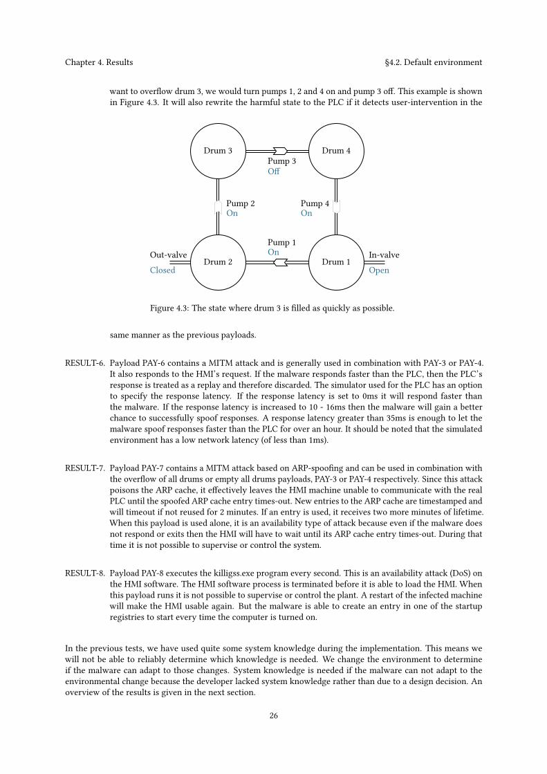
Chapter 4. Results §4.2. Default environment
want to overflow drum 3, we would turn pumps 1, 2 and 4 on and pump 3 off. This example is shownin Figure 4.3. It will also rewrite the harmful state to the PLC if it detects user-intervention in the
On
Pump 2
Pump 3
In-valveOut-valveDrum 1Drum 2
Drum 3 Drum 4
Pump 1
Pump 4On
Off
On
OpenClosed
Figure 4.3: The state where drum 3 is filled as quickly as possible.
same manner as the previous payloads.
RESULT-6. Payload PAY-6 contains a MITM attack and is generally used in combination with PAY-3 or PAY-4.It also responds to the HMI’s request. If the malware responds faster than the PLC, then the PLC’sresponse is treated as a replay and therefore discarded. The simulator used for the PLC has an optionto specify the response latency. If the response latency is set to 0ms it will respond faster thanthe malware. If the response latency is increased to 10 - 16ms then the malware will gain a betterchance to successfully spoof responses. A response latency greater than 35ms is enough to let themalware spoof responses faster than the PLC for over an hour. It should be noted that the simulatedenvironment has a low network latency (of less than 1ms).
RESULT-7. Payload PAY-7 contains a MITM attack based on ARP-spoofing and can be used in combination withthe overflow of all drums or empty all drums payloads, PAY-3 or PAY-4 respectively. Since this attackpoisons the ARP cache, it effectively leaves the HMI machine unable to communicate with the realPLC until the spoofed ARP cache entry times-out. New entries to the ARP cache are timestamped andwill timeout if not reused for 2 minutes. If an entry is used, it receives two more minutes of lifetime.When this payload is used alone, it is an availability type of attack because even if the malware doesnot respond or exits then the HMI will have to wait until its ARP cache entry times-out. During thattime it is not possible to supervise or control the system.
RESULT-8. Payload PAY-8 executes the killigss.exe program every second. This is an availability attack (DoS) onthe HMI software. The HMI software process is terminated before it is able to load the HMI. Whenthis payload runs it is not possible to supervise or control the plant. A restart of the infected machinewill make the HMI usable again. But the malware is able to create an entry in one of the startupregistries to start every time the computer is turned on.
In the previous tests, we have used quite some system knowledge during the implementation. This means wewill not be able to reliably determine which knowledge is needed. We change the environment to determineif the malware can adapt to those changes. System knowledge is needed if the malware can not adapt to theenvironmental change because the developer lacked system knowledge rather than due to a design decision. Anoverview of the results is given in the next section.
26
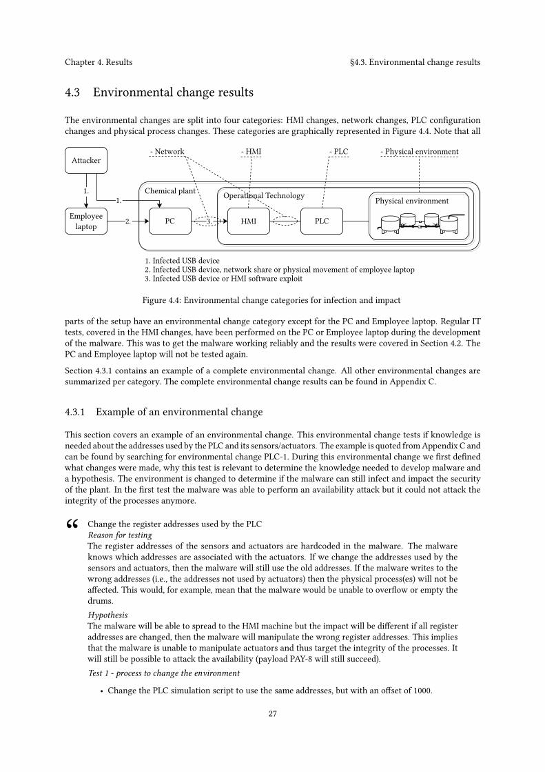
Chapter 4. Results §4.3. Environmental change results
4.3 Environmental change results
The environmental changes are split into four categories: HMI changes, network changes, PLC configurationchanges and physical process changes. These categories are graphically represented in Figure 4.4. Note that all
- HMI
1.
2.
Chemical plant Operational Technology
1. Infected USB device2. Infected USB device, network share or physical movement of employee laptop3. Infected USB device or HMI software exploit
Employeelaptop HMI
Physical environment
- Network - PLC - Physical environment
PLCPC
Attacker
3.
1.
Figure 4.4: Environmental change categories for infection and impact
parts of the setup have an environmental change category except for the PC and Employee laptop. Regular ITtests, covered in the HMI changes, have been performed on the PC or Employee laptop during the developmentof the malware. This was to get the malware working reliably and the results were covered in Section 4.2. ThePC and Employee laptop will not be tested again.
Section 4.3.1 contains an example of a complete environmental change. All other environmental changes aresummarized per category. The complete environmental change results can be found in Appendix C.
4.3.1 Example of an environmental change
This section covers an example of an environmental change. This environmental change tests if knowledge isneeded about the addresses used by the PLC and its sensors/actuators. The example is quoted fromAppendix C andcan be found by searching for environmental change PLC-1. During this environmental change we first definedwhat changes were made, why this test is relevant to determine the knowledge needed to develop malware anda hypothesis. The environment is changed to determine if the malware can still infect and impact the securityof the plant. In the first test the malware was able to perform an availability attack but it could not attack theintegrity of the processes anymore.
“ Change the register addresses used by the PLCReason for testingThe register addresses of the sensors and actuators are hardcoded in the malware. The malwareknows which addresses are associated with the actuators. If we change the addresses used by thesensors and actuators, then the malware will still use the old addresses. If the malware writes to thewrong addresses (i.e., the addresses not used by actuators) then the physical process(es) will not beaffected. This would, for example, mean that the malware would be unable to overflow or empty thedrums.HypothesisThe malware will be able to spread to the HMI machine but the impact will be different if all registeraddresses are changed, then the malware will manipulate the wrong register addresses. This impliesthat the malware is unable to manipulate actuators and thus target the integrity of the processes. Itwill still be possible to attack the availability (payload PAY-8 will still succeed).Test 1 - process to change the environment
• Change the PLC simulation script to use the same addresses, but with an offset of 1000.
27
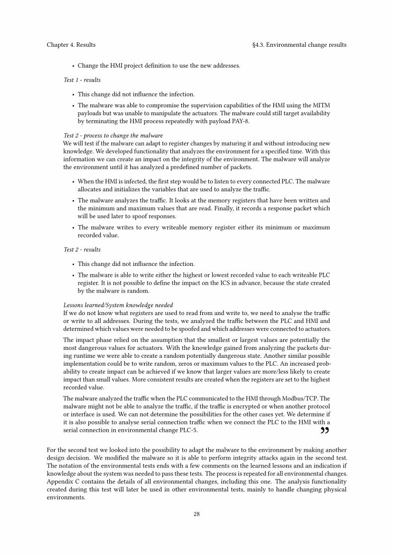
Chapter 4. Results §4.3. Environmental change results
• Change the HMI project definition to use the new addresses.
Test 1 - results
• This change did not influence the infection.• The malware was able to compromise the supervision capabilities of the HMI using the MITMpayloads but was unable to manipulate the actuators. The malware could still target availabilityby terminating the HMI process repeatedly with payload PAY-8.
Test 2 - process to change the malwareWe will test if the malware can adapt to register changes by maturing it and without introducing newknowledge. We developed functionality that analyzes the environment for a specified time. With thisinformation we can create an impact on the integrity of the environment. The malware will analyzethe environment until it has analyzed a predefined number of packets.
• When the HMI is infected, the first step would be to listen to every connected PLC. The malwareallocates and initializes the variables that are used to analyze the traffic.
• The malware analyzes the traffic. It looks at the memory registers that have been written andthe minimum and maximum values that are read. Finally, it records a response packet whichwill be used later to spoof responses.
• The malware writes to every writeable memory register either its minimum or maximumrecorded value.
Test 2 - results
• This change did not influence the infection.• The malware is able to write either the highest or lowest recorded value to each writeable PLCregister. It is not possible to define the impact on the ICS in advance, because the state createdby the malware is random.
Lessons learned/System knowledge neededIf we do not know what registers are used to read from and write to, we need to analyse the trafficor write to all addresses. During the tests, we analyzed the traffic between the PLC and HMI anddeterminedwhich values were needed to be spoofed andwhich addresses were connected to actuators.The impact phase relied on the assumption that the smallest or largest values are potentially themost dangerous values for actuators. With the knowledge gained from analyzing the packets dur-ing runtime we were able to create a random potentially dangerous state. Another similar possibleimplementation could be to write random, zeros or maximum values to the PLC. An increased prob-ability to create impact can be achieved if we know that larger values are more/less likely to createimpact than small values. More consistent results are created when the registers are set to the highestrecorded value.The malware analyzed the traffic when the PLC communicated to the HMI throughModbus/TCP. Themalware might not be able to analyze the traffic, if the traffic is encrypted or when another protocolor interface is used. We can not determine the possibilities for the other cases yet. We determine ifit is also possible to analyse serial connection traffic when we connect the PLC to the HMI with aserial connection in environmental change PLC-5. ”
For the second test we looked into the possibility to adapt the malware to the environment by making anotherdesign decision. We modified the malware so it is able to perform integrity attacks again in the second test.The notation of the environmental tests ends with a few comments on the learned lessons and an indication ifknowledge about the systemwas needed to pass these tests. The process is repeated for all environmental changes.Appendix C contains the details of all environmental changes, including this one. The analysis functionalitycreated during this test will later be used in other environmental tests, mainly to handle changing physicalenvironments.
28
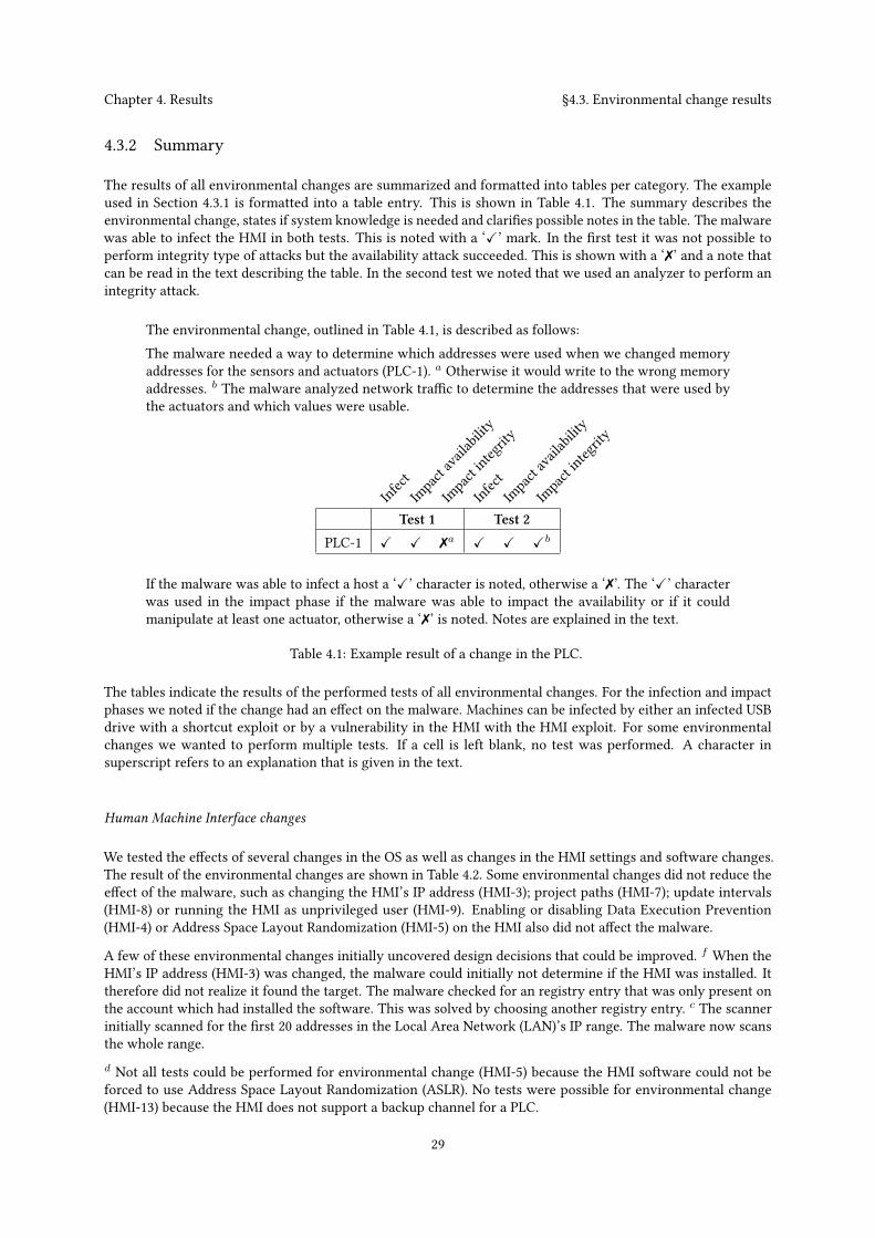
Chapter 4. Results §4.3. Environmental change results
4.3.2 Summary
The results of all environmental changes are summarized and formatted into tables per category. The exampleused in Section 4.3.1 is formatted into a table entry. This is shown in Table 4.1. The summary describes theenvironmental change, states if system knowledge is needed and clarifies possible notes in the table. The malwarewas able to infect the HMI in both tests. This is noted with a ‘X’ mark. In the first test it was not possible toperform integrity type of attacks but the availability attack succeeded. This is shown with a ‘✗’ and a note thatcan be read in the text describing the table. In the second test we noted that we used an analyzer to perform anintegrity attack.
The environmental change, outlined in Table 4.1, is described as follows:The malware needed a way to determine which addresses were used when we changed memoryaddresses for the sensors and actuators (PLC-1). a Otherwise it would write to the wrong memoryaddresses. b The malware analyzed network traffic to determine the addresses that were used bythe actuators and which values were usable.
Infect
Impact availability
Impact integrity
Infect
Impact availability
Impact integrity
Test 1 Test 2
PLC-1 X X ✗a X X Xb
If the malware was able to infect a host a ‘X’ character is noted, otherwise a ‘✗’. The ‘X’ characterwas used in the impact phase if the malware was able to impact the availability or if it couldmanipulate at least one actuator, otherwise a ‘✗’ is noted. Notes are explained in the text.
Table 4.1: Example result of a change in the PLC.
The tables indicate the results of the performed tests of all environmental changes. For the infection and impactphases we noted if the change had an effect on the malware. Machines can be infected by either an infected USBdrive with a shortcut exploit or by a vulnerability in the HMI with the HMI exploit. For some environmentalchanges we wanted to perform multiple tests. If a cell is left blank, no test was performed. A character insuperscript refers to an explanation that is given in the text.
Human Machine Interface changes
We tested the effects of several changes in the OS as well as changes in the HMI settings and software changes.The result of the environmental changes are shown in Table 4.2. Some environmental changes did not reduce theeffect of the malware, such as changing the HMI’s IP address (HMI-3); project paths (HMI-7); update intervals(HMI-8) or running the HMI as unprivileged user (HMI-9). Enabling or disabling Data Execution Prevention(HMI-4) or Address Space Layout Randomization (HMI-5) on the HMI also did not affect the malware.
A few of these environmental changes initially uncovered design decisions that could be improved. f When theHMI’s IP address (HMI-3) was changed, the malware could initially not determine if the HMI was installed. Ittherefore did not realize it found the target. The malware checked for an registry entry that was only present onthe account which had installed the software. This was solved by choosing another registry entry. c The scannerinitially scanned for the first 20 addresses in the Local Area Network (LAN)’s IP range. The malware now scansthe whole range.d Not all tests could be performed for environmental change (HMI-5) because the HMI software could not beforced to use Address Space Layout Randomization (ASLR). No tests were possible for environmental change(HMI-13) because the HMI does not support a backup channel for a PLC.
29
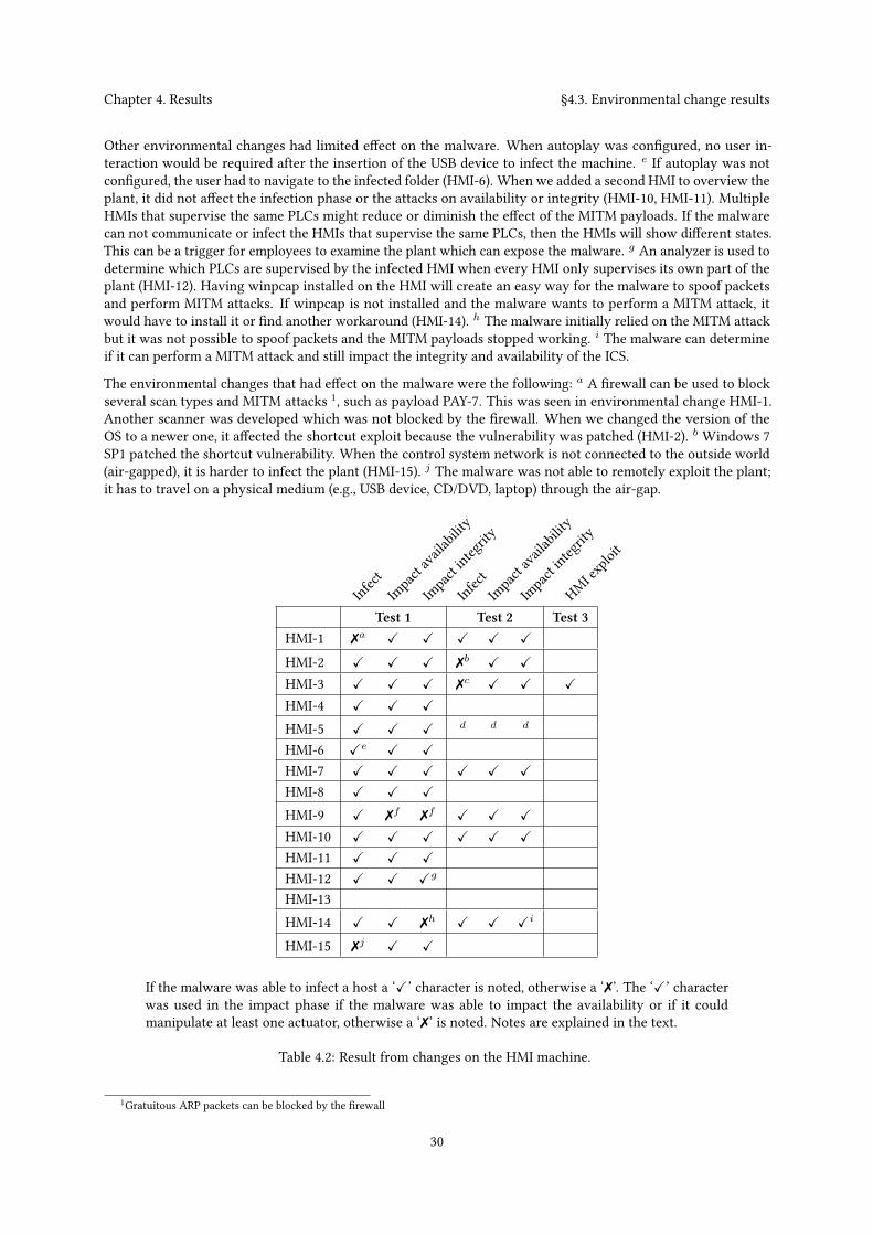
Chapter 4. Results §4.3. Environmental change results
Other environmental changes had limited effect on the malware. When autoplay was configured, no user in-teraction would be required after the insertion of the USB device to infect the machine. e If autoplay was notconfigured, the user had to navigate to the infected folder (HMI-6). When we added a second HMI to overview theplant, it did not affect the infection phase or the attacks on availability or integrity (HMI-10, HMI-11). MultipleHMIs that supervise the same PLCs might reduce or diminish the effect of the MITM payloads. If the malwarecan not communicate or infect the HMIs that supervise the same PLCs, then the HMIs will show different states.This can be a trigger for employees to examine the plant which can expose the malware. g An analyzer is used todetermine which PLCs are supervised by the infected HMI when every HMI only supervises its own part of theplant (HMI-12). Having winpcap installed on the HMI will create an easy way for the malware to spoof packetsand perform MITM attacks. If winpcap is not installed and the malware wants to perform a MITM attack, itwould have to install it or find another workaround (HMI-14). h The malware initially relied on the MITM attackbut it was not possible to spoof packets and the MITM payloads stopped working. i The malware can determineif it can perform a MITM attack and still impact the integrity and availability of the ICS.
The environmental changes that had effect on the malware were the following: a A firewall can be used to blockseveral scan types and MITM attacks 1, such as payload PAY-7. This was seen in environmental change HMI-1.Another scanner was developed which was not blocked by the firewall. When we changed the version of theOS to a newer one, it affected the shortcut exploit because the vulnerability was patched (HMI-2). b Windows 7SP1 patched the shortcut vulnerability. When the control system network is not connected to the outside world(air-gapped), it is harder to infect the plant (HMI-15). j The malware was not able to remotely exploit the plant;it has to travel on a physical medium (e.g., USB device, CD/DVD, laptop) through the air-gap.
Infect
Impact availability
Impact integrity
Infect
Impact availability
Impact integrity
HMI exploit
Test 1 Test 2 Test 3HMI-1 ✗a X X X X X
HMI-2 X X X ✗b X X
HMI-3 X X X ✗c X X X
HMI-4 X X X
HMI-5 X X X d d d
HMI-6 Xe X X
HMI-7 X X X X X X
HMI-8 X X X
HMI-9 X ✗f ✗f X X X
HMI-10 X X X X X X
HMI-11 X X X
HMI-12 X X Xg
HMI-13HMI-14 X X ✗h X X Xi
HMI-15 ✗j X X
If the malware was able to infect a host a ‘X’ character is noted, otherwise a ‘✗’. The ‘X’ characterwas used in the impact phase if the malware was able to impact the availability or if it couldmanipulate at least one actuator, otherwise a ‘✗’ is noted. Notes are explained in the text.
Table 4.2: Result from changes on the HMI machine.
1Gratuitous ARP packets can be blocked by the firewall
30
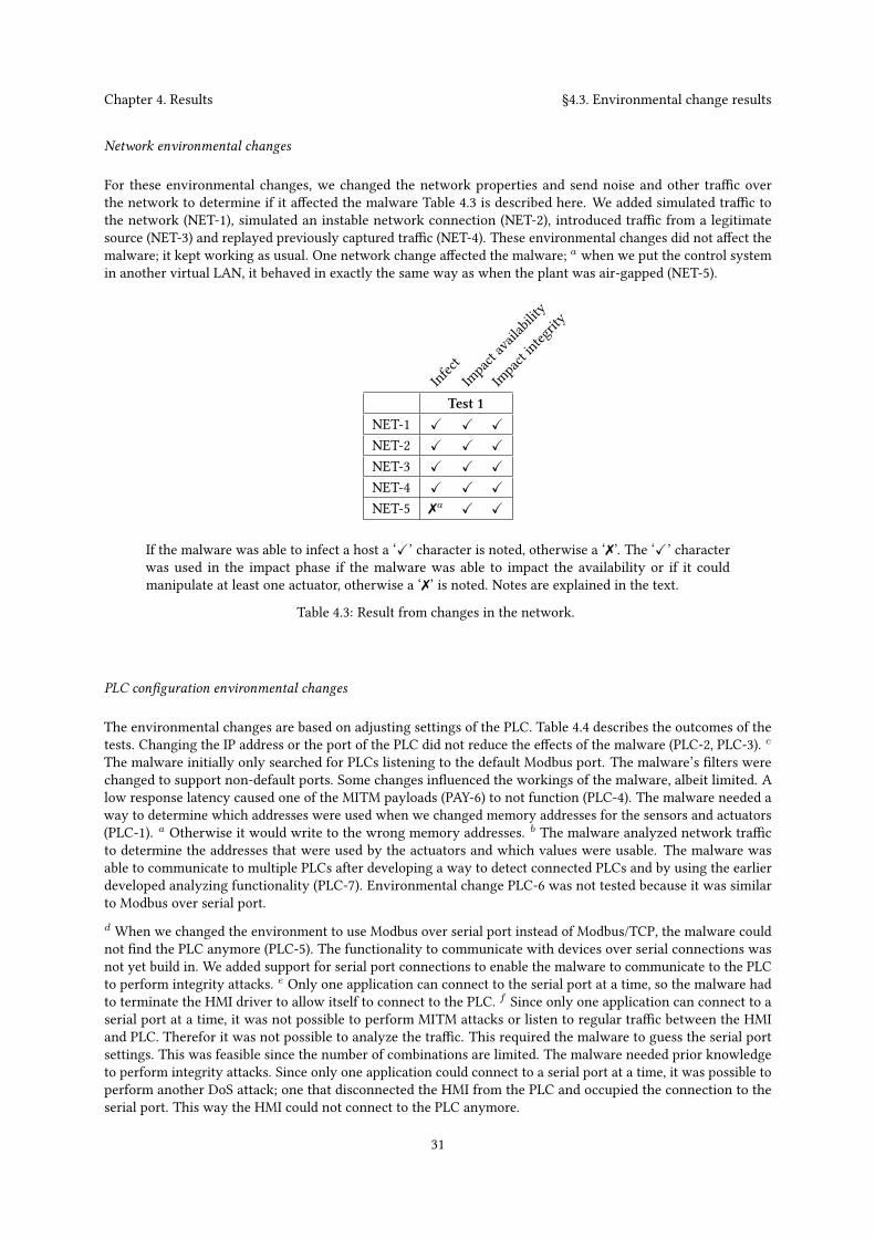
Chapter 4. Results §4.3. Environmental change results
Network environmental changes
For these environmental changes, we changed the network properties and send noise and other traffic overthe network to determine if it affected the malware Table 4.3 is described here. We added simulated traffic tothe network (NET-1), simulated an instable network connection (NET-2), introduced traffic from a legitimatesource (NET-3) and replayed previously captured traffic (NET-4). These environmental changes did not affect themalware; it kept working as usual. One network change affected the malware; a when we put the control systemin another virtual LAN, it behaved in exactly the same way as when the plant was air-gapped (NET-5).
Infect
Impact availability
Impact integrity
Test 1NET-1 X X X
NET-2 X X X
NET-3 X X X
NET-4 X X X
NET-5 ✗a X X
If the malware was able to infect a host a ‘X’ character is noted, otherwise a ‘✗’. The ‘X’ characterwas used in the impact phase if the malware was able to impact the availability or if it couldmanipulate at least one actuator, otherwise a ‘✗’ is noted. Notes are explained in the text.
Table 4.3: Result from changes in the network.
PLC configuration environmental changes
The environmental changes are based on adjusting settings of the PLC. Table 4.4 describes the outcomes of thetests. Changing the IP address or the port of the PLC did not reduce the effects of the malware (PLC-2, PLC-3). cThe malware initially only searched for PLCs listening to the default Modbus port. The malware’s filters werechanged to support non-default ports. Some changes influenced the workings of the malware, albeit limited. Alow response latency caused one of the MITM payloads (PAY-6) to not function (PLC-4). The malware needed away to determine which addresses were used when we changed memory addresses for the sensors and actuators(PLC-1). a Otherwise it would write to the wrong memory addresses. b The malware analyzed network trafficto determine the addresses that were used by the actuators and which values were usable. The malware wasable to communicate to multiple PLCs after developing a way to detect connected PLCs and by using the earlierdeveloped analyzing functionality (PLC-7). Environmental change PLC-6 was not tested because it was similarto Modbus over serial port.d When we changed the environment to use Modbus over serial port instead of Modbus/TCP, the malware couldnot find the PLC anymore (PLC-5). The functionality to communicate with devices over serial connections wasnot yet build in. We added support for serial port connections to enable the malware to communicate to the PLCto perform integrity attacks. e Only one application can connect to the serial port at a time, so the malware hadto terminate the HMI driver to allow itself to connect to the PLC. f Since only one application can connect to aserial port at a time, it was not possible to perform MITM attacks or listen to regular traffic between the HMIand PLC. Therefor it was not possible to analyze the traffic. This required the malware to guess the serial portsettings. This was feasible since the number of combinations are limited. The malware needed prior knowledgeto perform integrity attacks. Since only one application could connect to a serial port at a time, it was possible toperform another DoS attack; one that disconnected the HMI from the PLC and occupied the connection to theserial port. This way the HMI could not connect to the PLC anymore.
31
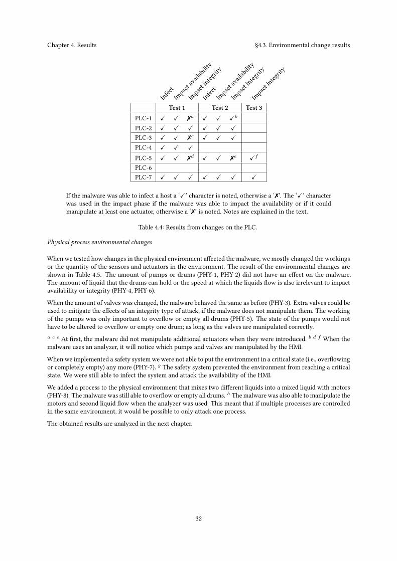
Chapter 4. Results §4.3. Environmental change results
Infect
Impact availability
Impact integrity
Infect
Impact availability
Impact integrity
Impact integrity
Test 1 Test 2 Test 3
PLC-1 X X ✗a X X Xb
PLC-2 X X X X X X
PLC-3 X X ✗c X X X
PLC-4 X X X
PLC-5 X X ✗d X X ✗e Xf
PLC-6PLC-7 X X X X X X X
If the malware was able to infect a host a ‘X’ character is noted, otherwise a ‘✗’. The ‘X’ characterwas used in the impact phase if the malware was able to impact the availability or if it couldmanipulate at least one actuator, otherwise a ‘✗’ is noted. Notes are explained in the text.
Table 4.4: Results from changes on the PLC.
Physical process environmental changes
When we tested how changes in the physical environment affected the malware, we mostly changed the workingsor the quantity of the sensors and actuators in the environment. The result of the environmental changes areshown in Table 4.5. The amount of pumps or drums (PHY-1, PHY-2) did not have an effect on the malware.The amount of liquid that the drums can hold or the speed at which the liquids flow is also irrelevant to impactavailability or integrity (PHY-4, PHY-6).
When the amount of valves was changed, the malware behaved the same as before (PHY-3). Extra valves could beused to mitigate the effects of an integrity type of attack, if the malware does not manipulate them. The workingof the pumps was only important to overflow or empty all drums (PHY-5). The state of the pumps would nothave to be altered to overflow or empty one drum; as long as the valves are manipulated correctly.a c e At first, the malware did not manipulate additional actuators when they were introduced. b d f When themalware uses an analyzer, it will notice which pumps and valves are manipulated by the HMI.
When we implemented a safety systemwe were not able to put the environment in a critical state (i.e., overflowingor completely empty) any more (PHY-7). g The safety system prevented the environment from reaching a criticalstate. We were still able to infect the system and attack the availability of the HMI.
We added a process to the physical environment that mixes two different liquids into a mixed liquid with motors(PHY-8). Themalware was still able to overflow or empty all drums. h Themalware was also able tomanipulate themotors and second liquid flow when the analyzer was used. This meant that if multiple processes are controlledin the same environment, it would be possible to only attack one process.
The obtained results are analyzed in the next chapter.
32
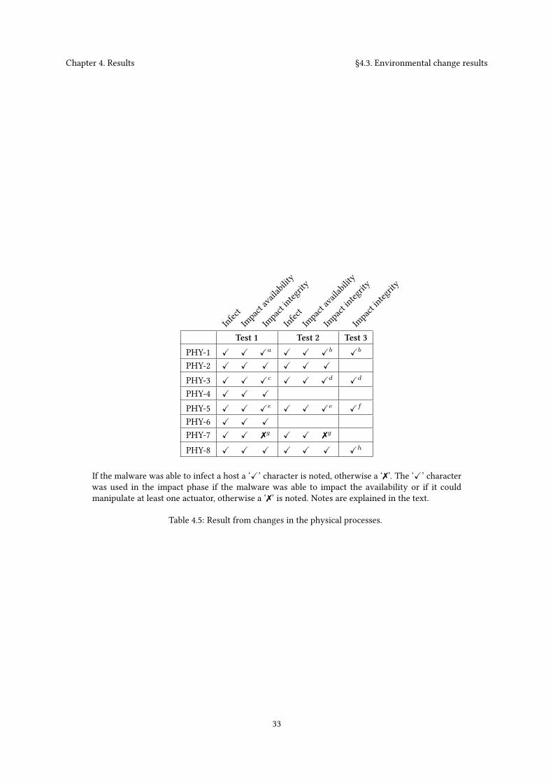
Chapter 4. Results §4.3. Environmental change results
Infect
Impact availability
Impact integrity
Infect
Impact availability
Impact integrity
Impact integrity
Test 1 Test 2 Test 3
PHY-1 X X Xa X X Xb Xb
PHY-2 X X X X X X
PHY-3 X X Xc X X Xd Xd
PHY-4 X X X
PHY-5 X X Xe X X Xe Xf
PHY-6 X X X
PHY-7 X X ✗g X X ✗g
PHY-8 X X X X X X Xh
If the malware was able to infect a host a ‘X’ character is noted, otherwise a ‘✗’. The ‘X’ characterwas used in the impact phase if the malware was able to impact the availability or if it couldmanipulate at least one actuator, otherwise a ‘✗’ is noted. Notes are explained in the text.
Table 4.5: Result from changes in the physical processes.
33

34

ChapterAnalysis5
This chapter describes the analysis of the results. First, the chapter defines the methodology to analyze the results.Then the chapter states the analysis of the environmental changes. The chapter ends with an answer to theresearch sub-questions.
5.1 Analysis methodology
We analyze the results of both research sub-questions separately.First, we analyze the result of each environmental change with regard to infection. If the malware’s impact wasreduced or diminished during the environmental changes, a closer look was taken at why the environmentalchange reduced or diminished the malware’s impact. In some cases, a design decision prevented the malwarefrom adapting to the changed environment. In those cases the design of the malware was revised withouthaving to introduce system knowledge. Furthermore, the lessons learned in the process of building and adaptingthe malware, were covered with regard to infection. Experiences and difficulties were highlighted and a fewenvironmental changes will be discussed and generalized. Finally, the analyzed results of the environmentalchanges and the lessons learned will help to answer to the research sub-question: “What system knowledge isrequired for malware to infect Industrial Control Systems?”.
The same steps were followed to analyze the results with regard to the impact on security. Finally, an answer wasgiven to the research sub-question: “What system knowledge is required for malware to impact the security ofan Industrial Control System?”.
5.2 System knowledge needed to infect ICSs
We defined the way malware spreads as the repeated process of infection, privilege escalation and propagation inSection 1.3. The focus lies on infection and propagation because the used exploits to infect the ICS do not requireadministrator privileges.
5.2.1 Analysis of environmental changes
Tables 5.1 and 5.2 were obtained from analyzing the obtained results and describe the required knowledge for themalware to spread to the ICS based on each environmental change.
Section 4.3 showed that the infection-phase was not affected by changes in the PLC configuration or physicalenvironment. The explanationwould obviously be: when themalware spread, it did not have a direct connection tothe PLC or physical environment until it reached the HMI. Therefore, changes in the PLC or physical environmentwould most likely not influence the infection stage.
5.2.2 Lessons learned
Lessons were learned during the development of the malware, when the impact of the malware on the unchangedenvironment was determined and when the effect of the environmental changes were tested.
35
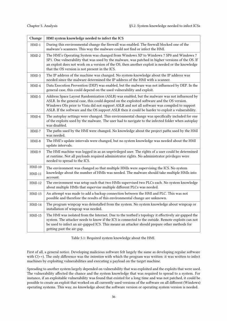
Chapter 5. Analysis §5.2. System knowledge needed to infect ICSs
Change HMI system knowledge needed to infect the ICS
HMI-1 During this environmental change the firewall was enabled. The firewall blocked one of themalware’s scanners. This way the malware could not find or infect the HMI.
HMI-2 The HMI’s Operating System was changed from Windows XP to Windows 7 SP0 and Windows 7SP1. One vulnerability that was used by the malware, was patched in higher versions of the OS. Ifan exploit does not work on a version of the OS, then another exploit is needed or the knowledgethat the OS version is not present in the ICS.
HMI-3 The IP address of the machine was changed. No system-knowledge about the IP address wasneeded since the malware determined the IP address of the HMI with a scanner.
HMI-4 Data Execution Prevention (DEP) was enabled, but the malware was not influenced by DEP. In thegeneral case, this could depend on the used vulnerability and exploit.
HMI-5 Address Space Layout Randomization (ASLR) was enabled, but the malware was not influenced byASLR. In the general case, this could depend on the exploited software and the OS version.Windows OSs prior to Vista did not support ASLR and not all software was compiled to supportASLR. If the software and the OS support ASLR then it could be harder to exploit a vulnerability.
HMI-6 The autoplay settings were changed. This environmental change was specifically included for oneof the exploits used by the malware. The user had to navigate to the infected folder when autoplaywas disabled.
HMI-7 The paths used by the HMI were changed. No knowledge about the project paths used by the HMIwas needed.
HMI-8 The HMI’s update intervals were changed, but no system knowledge was needed about the HMIupdate intervals.
HMI-9 The HMI machine was logged in as an unprivileged user. The rights of a user could be determinedat runtime. Not all payloads required administrator rights. No administrator privileges wereneeded to spread to the ICS.
HMI-10
HMI-11The environment was changed so that multiple HMIs were supervising the ICS. No systemknowledge about the number of HMIs was needed. The malware should take multiple HMIs intoaccount.
HMI-12 The environment was setup such that two HMIs supervised two PLCs each. No system knowledgeabout multiple HMIs that supervise multiple different PLCs was needed.
HMI-13 An attempt was made to add a backup connection between the HMI and PLC. This was notpossible and therefore the results of this environmental change are unknown.
HMI-14 The program winpcap was deïnstalled from the system. No system knowledge about winpcap orinstallation of winpcap was needed.
HMI-15 The HMI was isolated from the Internet. Due to the testbed’s topology it effectively air-gapped thesystem. The attacker needs to know if the ICS is connected to the outside. Remote exploits can notbe used to infect an air-gapped ICS. This means an attacker should prepare other methods forgetting past the air-gap.
Table 5.1: Required system knowledge about the HMI.
First of all, a general notice. Developing malicious software felt largely the same as developing regular softwarewith C(++). The only difference was the intention with which the program was written: it was written to infectmachines by exploiting vulnerabilities and executing a payload on the target machine.
Spreading to another system largely depended on vulnerability that was exploited and the exploits that were used.The vulnerability affected the chance and the system knowledge that was required to spread to a system. Forinstance, if an exploitable vulnerability was found that existed for a long time and was not patched, it could bepossible to create an exploit that worked on all currently used versions of the software on all different (Windows)operating systems. This way, no knowledge about the software version or operating system version is needed.
36
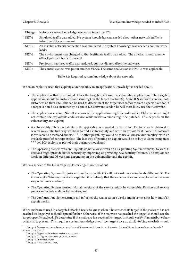
Chapter 5. Analysis §5.2. System knowledge needed to infect ICSs
Change Network system knowledge needed to infect the ICS
NET-1 Simulated traffic was added. No system knowledge was needed about other network traffic toinfect the ICS environment.
NET-2 An instable network connection was simulated. No system knowledge was needed about networkloads.
NET-3 The environment was changed so that legitimate traffic was added. The attacker should assumeother legitimate traffic is present.
NET-4 Previously captured traffic was replayed, but this did not affect the malware.NET-5 The control system was put in another VLAN. The same analysis as in HMI-15 was applicable.
Table 5.2: Required system knowledge about the network.
When an exploit is used that exploits a vulnerability in an application, knowledge is needed about:
• The application that is exploited: Does the targeted ICS use the vulnerable application? The targetedapplication should be installed (and running) on the target machine(s). Some ICS software vendors notecustomers on their site. This can be used to determine if the target uses software from a specific vendor. Ifa target is noted as a customer by a certain ICS software vendor, he will most likely use their software;
• The application version: Not all versions of the application might be vulnerable. Older versions mightnot contain the exploitable code/service while newer versions might be patched. This depends on thevulnerability and exploit;
• A vulnerability: The vulnerability in the application is exploited by the exploit. Exploits can be obtained inseveral ways. The first way would be to find a vulnerability and write an exploit for it. Some ICS softwareis available to download and use 1 2. Another possibility would be to use a ‘known vulnerability’ with anavailable proof of concept exploit. The last way of gaining an exploit would be to buy it. Some companies3 4 5 sell ICS exploits as part of their business model; and
• The Operating System version: Exploits do not always work on all Operating System versions. Newer OSversions might provide better security by improving or providing new security features. The exploit canwork on different OS versions depending on the vulnerability and the exploit.
When a service of the OS is targeted, knowledge is needed about:
• The Operating System: Exploits written for a specific OS will not work on a completely different OS. Forinstance; if a Windows service is exploited it is unlikely that the same service can be exploited in the sameway on a Linux machine;
• The Operating System version: Not all versions of the service might be vulnerable. Patches and servicepacks can include updates for services; and
• The configuration: Some settings can influence the way a service works and in some cases how and if anexploit works.
When malware is used in a targeted attack it needs to know when it has reached its target. If the malware has notreached its target yet it should spread further. Otherwise, if the malware has reached the target, it should use thetarget-specific payload. To determine if the malware has reached its target, it should verify if an attribute/char-acteristic is present. This requires system knowledge about the target since an attribute/characteristic should
1http://automation.siemens.com/mcms/human-machine-interface/en/visualization-software/scada/simatic-wincc/
2http://igss.schneider-electric.com/3http://gleg.net/agora_scada.shtml4http://revuln.com/5http://www.vupen.com/
37

Chapter 5. Analysis §5.2. System knowledge needed to infect ICSs
be known in advance. Examples of characteristics or unique properties are: a MAC address; an IP address (orrange); the presence of a specific software package; aWindows license key; the use of industrial protocols and/or adomain name or computer name. The malware will execute its payload on the systems that have the characteristicor unique property. If a non-unique property is used, then the malware can possibly impact nontargets.
5.2.3 Conclusion
The analysis and the learned lessons were used to list the knowledge needed to infect an ICS. First, the knowledgeneeded during the development is discussed and then the knowledge needed that should be obtained at runtime.The system knowledge needed during development to infect an ICS is listed here.
The interesting findings were that the malware developer needs to know:
• If custom firewall rules are configured and which custom firewall rules are configured.If custom firewall rules were configured, then the firewall can block the malware’s scans or networkcommunication. If the firewall blocks a scan, then the malware will not find any other machine which canresult in the malware not executing a remote exploit against connected and vulnerable targets.
• If the ICS is physically isolated from other networks (air-gapped).If the ICS is air-gapped, then the malware will need to be moved through the air-gap. This implies that atleast one scenario and exploit should be developed that is compatible with physically moving the malwarethrough the air-gap. A few example scenarios for moving the malware through the air-gap are by physicallytransporting, walking, dropping or throwing the malware on a USB stick, laptop or WiFi-hotspot devicethrough the air-gap. After the malware has reached the ICS it should be executed. This can require anexploit.
• A unique property of the target to determine if the malware has reached its target.Since the malware should behave differently when it has not reached its target than when it has reachedits target, it should be able to make that distinction.
And the malware developers that target ICSs also need to know:
• The Operating System (e.g., Windows, Linux) and OS versions used in the ICS.(Malicious) software written for Windows OSs will generally not work on Linux based OSs and vice versa.Knowledge about the version is needed if the used exploits do not run on all versions of a specific OS. Ifthe ICS contains versions of the OS that are not compatible with the exploit, then the malware will not beable to infect the ICS.
• The software and software versions used in the ICS (to supervise and control the PLCs).More exploits can be included in the malware depending on the knowledge of the software used by thetargeted ICS. If the attacker downloads/buys the software he could search for remote exploits and experiencehow the software reacts to exploits.
• Vulnerabilities and exploits.One or preferably more exploits that work with the OS and software versions are needed. If knowledge isobtained about the OS/software versions or patch frequency, a decision can bemade if known vulnerabilitiescan be used. A privilege escalation exploit would be needed if the malware contains functionalities thatrequire administrator privileges.
System knowledge that the malware needs to obtain at runtime:
• Which machines/devices can be targeted.One way to infect other machines, is to infect machines in the LAN. A scan can be performed to learnwhich machines are present in the LAN. Other ways to infect other machines are to infect shared media,such as, USB-drives, printers or network shares.
38
Chapter 5. Analysis §5.3. System knowledge needed to impact the security of ICSs
• If a machine is vulnerable to the remote exploits contained by the malware.If a machine is vulnerable, then the malware will run the corresponding exploit and it will propagate to themachine.
• If the current machine is the final target machine.The malware needs to determine if the current machine is the final target. If not, the malware will try tospread further. If the current machine is the final target, then the malware will run a special payload. Itshould check if a unique property, that was defined during development, is present in the current machineor its environment.
5.3 System knowledge needed to impact the security of ICSs
The impact on security was defined as an attack on availability or integrity. An attack on integrity was performedwhen the malware changed at least one of the actuators of the system. An attack on availability was successfulwhen it stopped engineers from supervising or controlling the ICS.
5.3.1 Analysis of environmental changes
Tables 5.3, 5.4 and 5.5 were obtained from analyzing all obtained results. The tables indicate for each environmentalchange the required knowledge to impact the security of the ICS.
The payloads used to impact the ICS were not affected by network changes, as seen in Section 4.3.
5.3.2 Lessons learned
Payload PAY-8, which targeted availability, succeeded almost every time during the environmental changesbecause DoS attacks on the HMI required little system knowledge. A few examples of attacks that targetedthe availability of the HMI were; poisoning the ARP cache, terminating the HMI process or simply shuttingdown/rebooting the HMI machine. Those availability attacks were less dependent on influences from the PLCsor physical environment than integrity attacks.
Spoofing traffic turned out to be a big challenge. As mentioned in Section 3.4.3 Windows XP SP2 and newerplace restrictions on the creation of raw TCP sockets. Without raw sockets it is not possible to modify Ethernetheaders like: destination MAC address; source MAC address; or source IP address. This made spoofing packets alot harder. One way to create raw TCP sockets was to use winpcap. Winpcap is a network interface and providesthe options to send raw data, but it has to be installed first. This enables attackers to spoof packets with malware.
When the MITM functionality was developed, the malware needed to listen and respond to requests. The malwarelistened to what was send over the network. It had to interpret Modbus traffic from connected PLCs and filterout all the other traffic (e.g., HMI synchronisation traffic or HTTP traffic). The malware used a filter that onlylet traffic to and from the connected PLCs through. A command-line tool, netstat 6, was used to enumerate theconnected PLCs (i.e., ports and IP addresses). This information was also used to differentiate between differentPLCs. To select the right connections with netstat, the name of the service responsible for communicating withthe PLCs was required.
Functionality was needed to analyze the physical environment when no prior system knowledge was available.The analyzer first enumerated all connected PLCs and allocated enough memory. It then listened to the traffic fora predefined number of useful responses (packets). The analyzer kept track of all minimum and maximum valuesthat the HMI read (read single or multiple registers) from the PLC. It also kept a record of all register-addressesthe HMI wrote to (write single or multiple register). Those addresses were used by the actuators and would laterbe used to write to (integrity attack). When the analyzer had almost received the predefined number of usefulresponses, it would also record read requests so they could later be used to spoof traffic.
6in environmental change PLC-7 test 2
39

Chapter 5. Analysis §5.3. System knowledge needed to impact the security of ICSs
Change HMI system knowledge needed to impact the system
HMI-1 During this environmental change the firewall was enabled. No system knowledge about thefirewall configuration was needed to impact the system. It was possible to create a local DoSattack or spoof packets to take over a connect.
HMI-2 The HMI’s Operating System was changed from Windows XP to Windows 7 SP0 and Windows 7SP1. No system knowledge about the used OS version was needed during the environmental tests.
HMI-3 The IP address of the machine was changed. No system-knowledge about IP addresses of the HMIwas needed since the malware was already on the machine and was able to request the IPaddresses of each network interface at runtime.
HMI-4 Data Execution Prevention (DEP) was enabled, but this was not relevant at the stage where themalware had already infected the system.
HMI-5 Address Space Layout Randomization (ASLR) was enabled, but this was not relevant at the stagewhere the malware had already infected the system.
HMI-6 The autoplay settings were changed. No knowledge about autoplay was needed.HMI-7 The paths used by the HMI were changed. No knowledge about the project paths used by the HMI
was needed.HMI-8 The HMI’s update intervals were changed, but this did not influence the malware. The used
physical environment did not contain time-critical processes. The outcome of this environmentalchange could be different in more time constraint or real-time environments.
HMI-9 The HMI machine was logged in as an unprivileged user. The malware also had limited privileges.The rights of a user could be determined at runtime. Not all payloads required administratorrights. The malware did not need administrator privileges to impact the ICS.
HMI-10
HMI-11
If multiple HMIs were present and supervising the same (part of the) system the malware shouldperform a MITM attack on as many HMIs as possible. For instance, if multiple HMIs supervise thesame (part of the) system and the malware performs a MITM attack on all except one, then thatHMI would be capable of reading the true system state and possibly be used to intervene. Nosystem knowledge was needed to impact the security. The number of HMIs only affected thesuccess of the MITM attacks. To perform a successful MITM attack, the malware needs:knowledge about the HMIs that supervise the process; an exploit to reprogram the PLC likeStuxnet did; or a thorough scan and be able to communicate with all HMIs to perform a MITM.
HMI-12 The environment was setup such that two HMIs supervised two PLCs each. The same knowledgewas needed as in environmental changes HMI-11 and PLC-7 combined.
HMI-13 An attempt was made to add a backup connection between the HMI and PLC. This was notpossible and therefore the results of this environmental change are unknown.
HMI-14 The program winpcap was deïnstalled from the system. Winpcap was not needed to impact theavailability or integrity of the ICS but the malware could not perform an MITM attack without it.
HMI-15 The HMI was isolated from the Internet. Due to the testbed’s topology it effectively air-gapped thesystem. No knowledge was needed about whether the ICS was air-gapped or not, to impact theICS. Once the malware infected the air-gapped ICS it could proceed as usual. The malware couldprobably not create a backdoor to communicate to a command and control server.
Table 5.3: Required system knowledge about the HMI.
When the analyzer was done, the malware started the MITM attack. It disconnected the PLCs from the HMIand wrote randomly either the lowest or highest value to each writable register address. It assumed that thelowest or highest values were most likely the worst settings, to create a potential dangerous state. Although notimplemented, it would be possible to analyze the effect of the written state and if the current state did not causethe appropriate effect write a new random state.
Other, but more protocol specific, ways exist to impact the security of the ICS. The Modbus/TCP protocol specifies
40

Chapter 5. Analysis §5.3. System knowledge needed to impact the security of ICSs
Change PLC system knowledge needed to impact the system
PLC-1 The addresses that were used for the sensors and actuators were changed. The malware couldanalyze which addresses were used at runtime if the PLC was connected via Ethernet and noencryption was used.
PLC-2 The IP address of the PLC was changed. No system-knowledge about IP addresses was neededsince the IP addresses of the PLCs were determined at runtime.
PLC-3 The PLC initially used the default Modbus port. Another port was configured for the PLC to listento. The ports used by the PLCs were determined at runtime.
PLC-4 The PLC’s response latency was changed but this did not reduce the malware’s impact.PLC-5 A serial connection was setup for the HMI to communicate with the PLC. If a serial interface was
used to connect the PLC to the HMI then the malware would need to know the baud rate. WhenModbus was used then the transition mode (i.e., RTU or ASCII) would also be needed. It was notpossible to analyze the traffic because it was not possible to open the same port twice withoutmodifying drivers or hardware. This means knowledge about the environment and whichaddresses were used to write to was needed.
PLC-6 The protocol used by the HMI and PLC was not changed to DF-1 because it would not create anynew insights compared with the previous environmental change.
PLC-7 The number of PLCs was changed but did not stop the malware from impacting the securityduring the environmental changes.
Table 5.4: Required system knowledge about the PLC.
Change Physical environment knowledge needed to impact the system
PHY-1 The number of pumps in the environment was changed. Some actuators are be more importantthan other actuators.
PHY-2 The number of drums were changed. The malware did not need knowledge about the amount ofdrums.
PHY-3 Addition in- or out-valves were added. The malware did not need to know the exact number of in-or out-valves to impact the environment. Additional valves could be used to prevent the systemfrom reaching a critical state.
PHY-4 The amount of liquid a drum could hold was altered. The malware did not need to know aboutthis. It could have been used to check if the integrity attack put the system in a critical state.
PHY-5 The working of the pumps was changed and this influenced the malware when it used thehardcoded values.
PHY-6 The flow speed of the liquid was changed, but this was not important for the malware to impactthe system.
PHY-7 When a safety system was added, it prevented the malware from overflowing or emptying drums.The attacker needs to know if a safety system is in place. This changes the available options toimpact the integrity of the system.
PHY-8 A process that required engaging motors for mixing the fluids in the tanks was added. When themalware targeted one process, it did not require knowledge about other processes.
Table 5.5: Required system knowledge about the physical processes.
the possibility to set/force the PLC to a ‘listen only’-mode. This creates a DoS attack since the HMI would not beable to read or write values from or to the PLC anymore. Another option in the Modbus/TCP protocol would bethe ‘restart communications’-option which forces a restart and power up self-tests of the PLC. If this is performedrepeatedly, it will be impossible for the HMI to control the system. Yet another option would be the followingscenario: every time a HMI sends a request, the PLC should respond within a timeframe. The PLC will usuallybe able to reply under normal circumstances, otherwise it has the option to send a ‘Slave Device Busy Exception
41
Chapter 5. Analysis §5.3. System knowledge needed to impact the security of ICSs
Code Delay’-response which notifies the HMI that the PLC is busy. An attacker can use this functionality topostpone an action or an alarm by responding with a ‘Slave Device Busy Exception Code Delay’ to a request.This would also create a DoS.
5.3.3 Conclusion
The analysis and the learned lessons were used to list the knowledge needed to impact the security of an ICS. Thesystem knowledge needed during development to impact the security of an ICS with malware is described here.
An interesting finding was that a malware developer would need to know:
• If it is possible to create a backdoor that has access to the Internet.A backdoor, created by the malware, that is able to communicate with a command and control server creates,the possibility to analyze the environment manually. The attacker can use the backdoor to determine whichsoftware is used to supervise the plant and which communication interfaces are used to communicate withthe PLC. The attacker can also obtain records of the traffic and HMI configurations and (project) files. TheHMI project files contain detailed information about the environment. A record of the traffic can revealthe communication protocols that are used, information about the processes, and how the actuators arecontrolled. An optimized payload can be developed based on this analysis;
A malware developer that target ICSs also needs to know:
• The software used to supervise and control the PLCs or the software used to program the PLCs.If the attacker knows which HMI software and which version of the software is used, it would be possible toeasily enumerate all connections made by the HMI and thus enumerate all connected PLCs. If the softwareis obtained then the attacker can experience how the software responds to MITM and DoS attacks. If thedeveloper knows which application is used to program the PLCs he might use it to exploit the applicationto reprogram the PLC;
• The communication interface and protocols used in the ICS, especially for communicating between theHMI and PLC.If the attacker wants to impact the integrity of the system but does not reprogram the PLC, then theattacker would have to communicate to the PLCs. The communication to the PLC is needed to manipulatethe actuators and attack the integrity of the processes in the ICS. This would require knowledge about thecommunication interface and protocols.It is possible to support multiple (most commonly used) protocols and determine the used protocol atruntime. If a protocol is used that uses authentication / encryption it will become harder or impossible toanalyze the environment. The malware can still impact the integrity of the environment if it writes randomdata to (all) addresses or if it uses another way to find the actuators. The use of authentication preventsspoofing traffic and performing MITM attacks. This would make it harder to completely hide the malware’spresence.Depending on the protocol, one or more interfaces (e.g., Ethernet, serial port) are supported. As seen inthe environmental changes, the used communication interface matters. The malware could analyze thetraffic and perform MITM attacks when Modbus/TCP was used in the ICS. The malware could not analyzethe traffic or perform a MITM attack any more when Modbus over a serial connection was used. Whena serial connected was used, it enabled an extra attack on availability by stopping the process that usesthe serial port and connecting and occupying the port. If it is not known which interface is used then themalware will have to support both Ethernet and serial port interfaces. If a serial connection is used, thenknowledge is needed about: the used baud rate; the number of data- and stop-bits; and depending on theprotocol, which mode is used;
• Knowledge about the physical processes controlled by the ICS.Since the attacker is performing a targeted attack, he should already know what the ICS does. The attackershould delve deeper into what processes are controlled by the ICS if he wants to put the system in a criticalstate. Knowledge about possible time-critical processes can create more options for the malware to impactthe security of the system;
42
Chapter 5. Analysis §5.3. System knowledge needed to impact the security of ICSs
• What equipment is in place and how the processes are controlled.The malware should manipulate the actuators if it wants to impact the integrity of the ICS. If the malwarewants to manipulate the processes in a controlled way, it should know what actions the actuators takedepending on the values. This requires knowledge about the installed sensors and actuators; and
• If a safety system is in place and what it protects.A safety system can protect the processes from reaching undesired or critical states. It can prevent malwarefrom putting the processes in a critical state.
System knowledge that the malware needs to obtain at runtime:
• A list of connected PLCs, their IP addresses and ports.During the attack, the malware needs to know which PLCs are connected. If the malware can not figureout which PLCs are connected it will likely not be able to impact the integrity of the ICS. If a malwaredeveloper has detailed information on the processes and how they are controlled, it is possible to hard-codeor search for this information at runtime. Otherwise, the malware can still impact the integrity of the ICSby manipulating every actuator the malware can find.
• Which addresses are read and which addresses are written to by the HMI.The malware analyzes the environment to know which addresses are read and which addresses are writtento. The values that are read from the PLC can be recorded to spoof traffic. The HMI writes to the addressesthat are used by the actuators. The malware can use those addresses to manipulate actuators and put thesystem into a critical state (e.g., overflowing). If the malware analyzes the minimum and maximum valuesread from the sensors it is possible to determine if the current manipulated state affects the state of thesystem.
43

44

ChapterRelated research6
This chapter will cover the related work discovered during the literature study phase.
6.1 State of the art in ICS simulation
Several testbeds were found during the literature study, such as the one described by Genge et al. [13] that wasbased on Emulab. Emulab is a network testbed that consists of hundreds of PCs hosted by the University ofUtah. Emulab can be used to create cyber components (e.g., SCADA servers, corporate network) and the paperdescribed a setup where Matlab Simulink was used to create physical processes. The testbed was used to measurethe impact of attacks against the cyber and physical parts of the system.
Another testbed described by Fovino et al. [10] uses an experimental test-bed, deployed in Italy. It is used tosimulate attack scenarios against SCADA systems and to test countermeasures in a safe way. The environmentreproduces the dynamics of a physical power plant with real PLCs and sensors. Four attack scenarios werepresented: a DoS attack on the Remote Authentication Dial in User Service (RADIUS); a computer worm; a processnetwork malware infection; and phishing attacks together with local DNS poisoning. A set of countermeasuresare proposed, such as the use of encryption and authentication for regular TCP/IP traffic as for SCADA traffic,and filtering and monitoring with firewalls and IDSs. This research also showed that the four attack scenarioswere realistic and feasible. The process network malware infection attack was similar to the malware developedin this thesis.
Genge et al. determined the impact of network infrastructure parameters to the effectiveness of cyber attacksagainst ICSs [12]. The research determined if network delays, packet losses, background traffic and control logicscheduling time influenced the outcome attacks against networked ICSs. The attack scenario involved an attackerthat is able to send legitimate Modbus packets/commands with the goal of bringing the control system in a criticalstate. The research showed that network delays, packet losses and background traffic have limited effect on theattack. This was also true for the environmental changes that were performed in this thesis.
Chunlei et al. assessed a representative simulated environment for SCADA security analysis [5]. The environmentincluded several PLCs from different vendors. Their results demonstrate the effectiveness and practicability ofthe simulation environment by showing that it was possible to perform an attack scenario. The attack scenarioconsisted of: 1) gaining access to the simulated SCADA system; 2) Gaining local SCADA access via the enterprisenetwork and scanning the network; and 3) Compromising the master device by exploiting a vulnerability. Themalware created during this thesis was also able to perform these steps on our environment.
Perez-Garcia et al. determined how different design choices, e.g., use of specific tools, can affect the repeatabilityof the experiments of an emulation testbed [22]. The testbed was based on the Emulab software. They showedthat Emulab’s scheduling mechanism, built-in packet generators and Iperf can sufficiently support repeatableexperiments. They also showed that TCPreplay did not support repeatable experiments and that an alternativetool named TCPivo should be used instead. TCPreplay was used in this thesis for environmental test NET-4.Repeatable experiments were not required for the purpose of replaying traffic to see if it interfered with themalware.
Reaves et al. propose a virtual testbed for industrial security research [23] that was created using Python. Thevirtual devices were able to communicate with each other, the simulator, and with actual ICS devices. The virtualdevices supported multiple protocols. Logging devices were developed to capture and replay virtual system traffic.
Genge et al. analyzed cyber-physical attacks on networked Industrial Control System [11]. This paper definedan efficient approach for conducting experiments that measure the impact of attacks on the cyber and physical
45

Chapter 6. Related research §6.2. State of the art in malware development
components of the ICS. It represented an advancement over existing approaches by using a hybrid architecture.It emulated the protocols and components such as the SCADA servers and PLCs and simulated the physical layerusing Matlab Simulink.
Morris et al. describes the Mississippi State University SCADA security laboratory [20]. The laboratory containsmultiple power and energy ICSs (i.e., a raised water tower, gas pipeline, factory conveyor and industrial blower)with functional physical processes controlled by commercial hardware and software. They made a distinctionbetween two categories based upon the communication type; serial port or Ethernet communications. Themalware developed in this thesis was also able to infect and impact both categories.
Wu and Kubara made a comparison of the tools and simulators for control system security studies [30]. Theyclassified the tools/simulators into four types according to their important characteristics. The four types were:single simulation tools for devices; network simulation tools; integration simulation tools; and realistic testbedtools. Finally they compared the complexity, realistic capability real-time simulation performance and simulatedsecurity events. The environment used in this thesis can be categorized as an integration simulation tool sinceit is setup by integrating different kinds of security simulation on devices, data, and network. The comparisonstates that the integration simulator has a ‘middle complexity’, a ‘high realistic capability’ and a ‘low real-timesimulation performance’. These statements seem representative for our environment because it was relativelyeasy to setup the environment, real SCADA software was used and this setup would likely not be able to simulatelarge ICS environments in realtime.
6.2 State of the art in malware development
The possibility to create ICS tailored malware with simulation software (MAlSim) has been researched [3, 21] byCarcano and Fovino et al. Both papers describe the same research that was performed by the same researchersbut they papers were published in different journals. These papers were the most relevant papers for this thesis.The papers describe the development of a worm that is able to communicate with PLCs over Modbus/TCP. Theworm has two infection steps. The worm first infects PCs in the Company Intranet from the Internet. Then, ifa infected PC opens a VPN connection, the worm spreads itself through the VPN and infect PCs in the processnetwork. If the worm discovers Modbus slaves in the network, it will communicate with them. Two scenarioswere created, a scenario to perform a DoS attack and a scenario to take control of the slaves. The DoS attackwas performed by sending Modbus packets to desynchronize or completely interrupt the master/slave Modbuscommand flow. They found that systems with a low scanning rate desynchronized faster than systems with ahigh scanning rate when they were under attack. The second scenario is created with the intention to take controlof the slaves by taking advantage of the lack of authentication and integrity verification. The worm code was alot more complex, but, potentially, also a lot more dangerous. The worm was developed in a incremental mannerand three prototypes were made in the process. The first prototype forced each coil in a sequence of coils toeither ON or OFF. Closing or opening the coils could have a very high impact in a SCADA system. The secondprototype targeted the input register. It wrote the biggest allowed value (i.e., a 16-bit word) to all registers. Thefinal prototype read the state of the coils and wrote the inverted state to each coil. This attack strategy completelychanged the coil configuration. It was stated that the attacker has to know at least the high-level details of thearchitecture of the system under attack in order to write an "attack strategy module" with high effectiveness.Which high-level details of the architecture of the system were needed was not clearly defined. This thesis’sgoal was to describe the needed knowledge, including details of the architecture, needed to write malware withpayloads ("attack strategy modules").
6.3 Comparable research with regard to impact on ICSs
Several ICS attack models and scenarios have been defined and the attack scenarios were staged at a testbed [29].An experimental setup with four water tanks was controlled over a wireless network. The setup was used toillustrate attack scenarios, their consequences, and potential counter-measures. A figure in the paper describes athree dimensional cyber-physical attack space which depicts several attack scenarios that were described in thepaper. The figure used in the paper is shown in Figure 6.1. One of axis describes the ‘a priori’ system knowledge
46
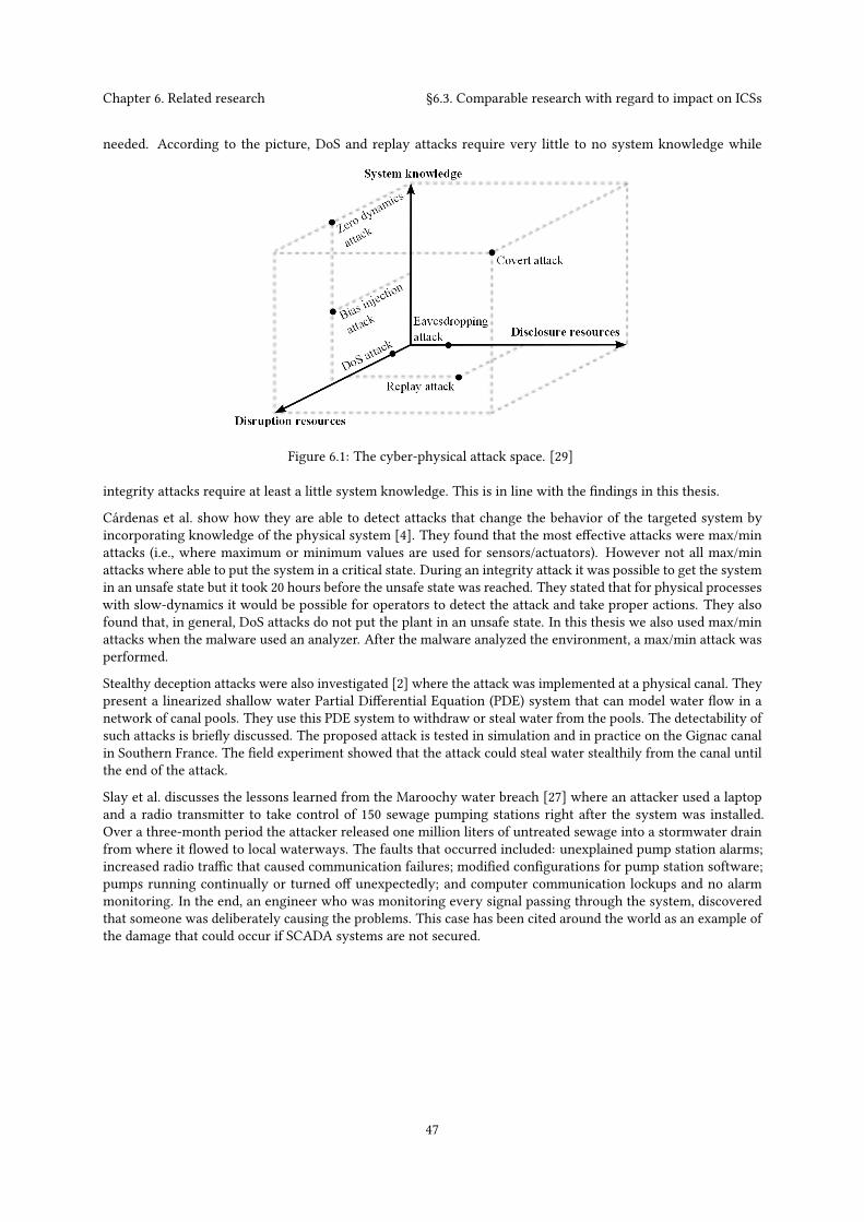
Chapter 6. Related research §6.3. Comparable research with regard to impact on ICSs
needed. According to the picture, DoS and replay attacks require very little to no system knowledge while
Figure 6.1: The cyber-physical attack space. [29]
integrity attacks require at least a little system knowledge. This is in line with the findings in this thesis.
Cárdenas et al. show how they are able to detect attacks that change the behavior of the targeted system byincorporating knowledge of the physical system [4]. They found that the most effective attacks were max/minattacks (i.e., where maximum or minimum values are used for sensors/actuators). However not all max/minattacks where able to put the system in a critical state. During an integrity attack it was possible to get the systemin an unsafe state but it took 20 hours before the unsafe state was reached. They stated that for physical processeswith slow-dynamics it would be possible for operators to detect the attack and take proper actions. They alsofound that, in general, DoS attacks do not put the plant in an unsafe state. In this thesis we also used max/minattacks when the malware used an analyzer. After the malware analyzed the environment, a max/min attack wasperformed.
Stealthy deception attacks were also investigated [2] where the attack was implemented at a physical canal. Theypresent a linearized shallow water Partial Differential Equation (PDE) system that can model water flow in anetwork of canal pools. They use this PDE system to withdraw or steal water from the pools. The detectability ofsuch attacks is briefly discussed. The proposed attack is tested in simulation and in practice on the Gignac canalin Southern France. The field experiment showed that the attack could steal water stealthily from the canal untilthe end of the attack.
Slay et al. discusses the lessons learned from the Maroochy water breach [27] where an attacker used a laptopand a radio transmitter to take control of 150 sewage pumping stations right after the system was installed.Over a three-month period the attacker released one million liters of untreated sewage into a stormwater drainfrom where it flowed to local waterways. The faults that occurred included: unexplained pump station alarms;increased radio traffic that caused communication failures; modified configurations for pump station software;pumps running continually or turned off unexpectedly; and computer communication lockups and no alarmmonitoring. In the end, an engineer who was monitoring every signal passing through the system, discoveredthat someone was deliberately causing the problems. This case has been cited around the world as an example ofthe damage that could occur if SCADA systems are not secured.
47

48

ChapterConclusions and future work7
In the introduction we identified the following problem, namely, that malicious software (malware) is omnipresentand that malware is now able to reach Industrial Control Systems (ICSs). This could cause financial loss or physicaldamage. Developingmalware that can infect and impact ICSs requires a certain amount of prior system knowledge.If the information needed to develop malware for a specific target was kept secret by ICS managers/employees,it would be harder to target that ICS using malware. This brought up the question: “What system knowledgeis needed for a malware developer to create malware to infect and impact an Industrial Control System?”. Wefirst need to answer the following two sub-questions: “What system knowledge is required for malware to infectIndustrial Control Systems?” and “What system knowledge is required for malware to impact the security ofan Industrial Control System?”. The methodology for answering the sub-questions was: first, setting up anenvironment and developing malware; then we prepared a list of possible changes in the environment after whichthe environment was changed according to one of the changes in the list; finally, the changes that reduced ordiminished the effects of the malware were determined.
This methodology could not be executed without learning about Industrial Control Systems first. The PurdueModel for Control Hierarchy described a model for typical control systems and the relevant components. Thedifference between ICSs and regular Information Technology (IT) systems was explained and the describedcomponents were used to setup an environment. We set up an environment to represent a chemical plant whichcontained drums, pumps and valves. We developed malware that was able to infect the plant and impact theintegrity and availability by disrupting plant supervision and overflowing or emptying the drums.
We prepared a list of possible environmental changes and the list was reviewed and completed by ICS andmalwarespecialists. This resulted in a list of 35 environmental changes. We changed the environment according to an itemon the list and determined if the change reduced or diminished the effects of the malware. System knowledgewas needed if the malware was unable to infect or impact the security of the plant when this was not caused bya design decision. These findings were analyzed and together with the learned lessons the sub-questions wereanswered.
This chapter concludes the research. First, the main research question will be answered. Then, possible improve-ments of the research are stated. Furthermore, the impact of the research is discussed. Finally, possible futurework is listed.
7.1 Answer to the research question
This section covers the answers to both sub-questions and the research question. The research question is statedas follows:
“What system knowledge is needed for a malware developer to create malware to infect and impact an IndustrialControl System?”
The research question was divided into two sub-questions which were answered separately. The answers arecombined to answer the research question. We expected some answers since they were quite obvious but we alsoobtained a answers that were quite interesting. A distinction is made between the expected and interesting items.
7.1.1 Answer to the first sub-question
We stated the second research question as:
“What system knowledge is required for malware to infect Industrial Control Systems?”
49

Chapter 7. Conclusions and future work §7.1. Answer to the research question
The way malware spreads was defined as the repeated process of infection, privilege escalation and propagation.The focus, to answer the research question, lies on infection and propagation because the used exploits do notrequire administrator privileges to propagate.
The interesting findings were that the malware developer needs to know:
• If custom firewall rules are configured and which custom firewall rules are configured.
• If the ICS is physically isolated from other networks (air-gapped).
• A unique property of the target to determine if the malware has reached its target.
And the malware developer that target ICSs also need to know:
• The Operating System (e.g., Windows, Linux) and Operating System (OS) versions used in the ICS.
• The software and software versions used in the ICS (to supervise and control the Programmable LogicControllers (PLCs)).
• Vulnerabilities and exploits.
7.1.2 Answer to the second sub-question
We stated the second research question as:
“What system knowledge is required for malware to impact the security of an Industrial Control System?”
The impact on security was defined as an attack on availability or integrity. An attack on integrity was performedwhen the malware changed at least one of the actuators of the system. An attack on availability was successfulwhen it stopped engineers from supervising or controlling the ICS.
An interesting finding was that a malware developer would need to know:
• If it is possible to create a backdoor that has access to the Internet.
A malware developer that target ICSs also needs to know:
• If a safety system is in place and what it protects.
• The software used to supervise and control the PLCs or the software used to program the PLCs.
• The communication interface and protocols used in the ICS, especially for communicating between theHuman Machine Interface (HMI) and PLC.
• Knowledge about the physical processes controlled by the ICS.
• What equipment is in place and how the processes are controlled.
7.1.3 Conclusion
Malware developers need to acquire certain knowledge to launch a targeted attack on an ICS.
If an attacker wants to impact the security of the ICS with malware, he needs to infect the ICS first. This requiresknowledge about what OSs (e.g., Windows, Linux) need to be infected. One or more exploits compatible withthe OS are needed to infect the targeted machines. Knowledge about the OS version is needed, depending on thevulnerabilities that the exploits target. If the target is not connected to the Internet (i.e., completely air-gapped)then an attack scenario with corresponding exploits is needed (e.g., a scenario where the malware infects USB-drives). Knowledge about firewalls and their rules will enable the attacker to develop malware that can spread
50
Chapter 7. Conclusions and future work §7.2. Improvements
and scan through networks without being blocked. The attacker should know a (unique) property of the targetso the malware can use that to detect if it has reached its target.
If the malware reaches a machine that can control the environment it will try to impact the integrity and/oravailability of the system. If the malware can create a backdoor that is able to communicate with a commandand control server, then it becomes possible for the attacker to analyze the environment manually. Otherwise,more knowledge would be needed during development, such as knowledge about the physical processes thatare controlled by the ICS and how the processes are controlled. Knowledge about the (Supervisory Control andData Acquisition (SCADA) or HMI) software used at the ICS can be used to develop extra exploits and enumerateconnected PLCs at runtime.
7.2 Improvements
During the research some improvements came tomind. Ideally, this researchwould have been done by two persons.One person would create and operate the ICS and the other would develop the malware. If both persons wouldnot discuss their setup and code, then it would be possible to more accurately measure the knowledge needed todevelop malware. The malware developer can test his malware on the unknown environment. If he needs moreknowledge to make the malware function, he can ask the ICS creator a question about the environment. The ICScreator would provide an answer and thus leak system knowledge. If the question and answers are documented,it would be possible to determine which system knowledge needed to be leaked to launch a targeted attack.
A weak point of the methodology was the generalization. The results of the environmental changes wheregeneralized. The generalizations are made for cases where malware wants to spread using remote exploits andan exploit compatible with portable media. The infected portable media can be used to infect other machines andto get past an airgap. In our case a remote exploit was used to infect the HMI. The answers obtained from theresearch gave few interesting findings. Nothing spectacular or ground breaking was discovered. The researchcould have given more interesting findings if a broader question was researched, for instance, “what knowledgeis needed to infect and impact the ICS stealthily?”.
If more time would have been spend in creating the questionnaire, then it would have been possible to get moreor higher quality answers. If the questionnaire was also send to an ICS or malware community, even more diverseenvironmental changes could have been obtained. This would also imply that more time was needed to testand analyze the additional information. A small improvement would have been to include privilege escalationexploits to the infection phase. Finally, the environment could have been setup more accurate by including aDemilitarized zone (DMZ). This would add another layer of security. But since the machines and software in theDMZ can contain vulnerabilities as well, it would only require one additional exploit for the malware to get pastthe DMZ. If the software used in the DMZ is made by the same vendor as the software used in the OperationalTechnology (OT) network, it could be the case that the vulnerability is present in both instances. This wouldmean only one exploit is needed to infect both machines.
7.3 Impact of the research
The problem description stated that malware was omnipresent and that it would require prior system-knowledgeto develop malware to infect and impact the security of an ICSs. The main impact of the research is that it providesa list of system knowledge that is needed to develop malware to infect and impact the security of an ICS. The listis not very large and some items can be guessed or easily obtained. This underlines the importance of securingICSs by airgapping, updating and patching them. As part of their defence in depth strategy, ICS staff should notshare the information described here to make it harder for malware developers to launch targeted attacks.
Attackers that are planning to target an ICS with malware will most likely start by learning as much as possibleabout their target. One of the easiest ways for attackers (malware developers) to gain Intel about a target isby obtaining the information using social engineering. When ICS management and engineers are aware of theinformation that should be secret, it would be easier to differentiate between a legitimate question and a social
51
Chapter 7. Conclusions and future work §7.4. Future work
engineering attack. This way, social engineering attacks can be spotted more easily making it even possible todetect the information gathering phase of a targeted attack.
The result of the research can also be used for forensics and incident response. When a malware sample isobtained, it is possible to more quickly determine if the malware is used for a targeted attack. If most of theinformation of the checklist is found, it will be likely that it is a targeted attack
7.4 Future work
The research also raised questions that could be researched in the future.
It would be interesting to determine the knowledge that is needed to infect and impact an ICS in a stealthy way.The result of the research combined with this research will provide a more complete picture of the requiredknowledge needed to stealthy infect and impact the security of the ICS. If malware is not stealthy, it can bediscovered more easily before the ICS is infected or before it impacted the security of the ICS. If the malware isvery stealthy it can take a long time before anyone detects it.
This research can also be performed with an emulated environment with real physical environment parametersor with a real ICS with physical components. This can provide more accurate insight into the knowledge neededto put the system in a critical state. If a real ICS setup is used, it would be interesting to look to the effect of certainprotocol specific commands that can be used to control the PLC’s behavior. For instance, theModbus/TransmissionControl Protocol (TCP) protocol specifies the possibility to set/force the PLC to a ‘listen only’ mode. The ‘restartcommunications’ option which forces a restart and power up self-tests of the PLC, could be used repeatedlyto make it impossible for the HMI to control the system. Future work can include a research to determinethe knowledge that is needed to reprogram a PLC. Future research could determine the knowledge needed formalware to communicate with PLCs using different protocols. Does it take more knowledge to use DF-1 insteadof Modbus? And how does encryption and authentication exactly influence the developer’s required knowledgeto create malware to impact the integrity of the ICS? Will authentication between the HMI and PLC completelyblock the malware from talking to the PLC? Or can the malware recover keys that are used by the HMI once ithas infected it? If different HMI software can be obtained, it would be possible to research the behavior of thesoftware on different Man-in-the-Middle (MITM) and availability attacks. This would require HMI software frommultiple vendors. Future research could provide more insight into the difference in knowledge that is needed toinfect and impact IT systems or Industrial Control Systems.
Future research could determine the knowledge needed for many other different physical environments. Doesit take more or different knowledge to impact the security of power plants, than to impact food manufacturingfacilities? This could provide ICS managers and engineers a more tailored advice on what information should bekept more securely.
Research could be performed to gain more insights into a human factor in control system security. How canmalware manipulate engineers to trick them into making wrong decisions to impact the integrity or availabilityof the system? Would manipulation of the data shown on the HMI be enough? If malware is able to impact theintegrity of the system, it could also do it with the purpose of triggering the safety system instead of putting thesystem in a critical state. The malware’s goal would be to trigger the safety system repeatedly during a MITMattack, to let the ICS engineers suspect that the safety system is not working properly. The malware can try toput the system in a critical state if the engineers take action towards the safety system by, for instance, ignoringit, disabling it or reprogramming it. How would engineers react to such an attack scenario?
Research into the remote access vendors use can provide new attack vectors. Is it possible to use this function-ality during attacks? What are the benefits for malware developers to target ICS vendors to obtain details andcredentials and attack ICS that way? Does this decrease the knowledge needed to write malware? And how canICS be secured against these attacks?
52
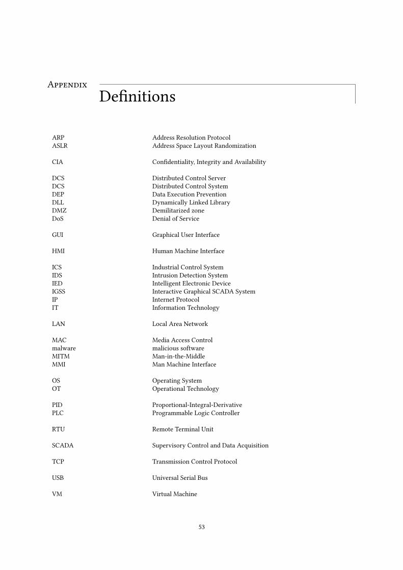
AppendixDefinitions
ARP Address Resolution ProtocolASLR Address Space Layout Randomization
CIA Confidentiality, Integrity and Availability
DCS Distributed Control ServerDCS Distributed Control SystemDEP Data Execution PreventionDLL Dynamically Linked LibraryDMZ Demilitarized zoneDoS Denial of Service
GUI Graphical User Interface
HMI Human Machine Interface
ICS Industrial Control SystemIDS Intrusion Detection SystemIED Intelligent Electronic DeviceIGSS Interactive Graphical SCADA SystemIP Internet ProtocolIT Information Technology
LAN Local Area Network
MAC Media Access Controlmalware malicious softwareMITM Man-in-the-MiddleMMI Man Machine Interface
OS Operating SystemOT Operational Technology
PID Proportional-Integral-DerivativePLC Programmable Logic Controller
RTU Remote Terminal Unit
SCADA Supervisory Control and Data Acquisition
TCP Transmission Control Protocol
USB Universal Serial Bus
VM Virtual Machine
53

54
AppendixQuestionnaireA
Dear,
A while ago I started writing my master-thesis for my Information Security study at Technical University Eind-hoven (The Netherlands). The subject of my master-thesis is: “What system-knowledge is needed for malware toinfect and impact Industrial Control Systems?”. To research this topic I created malware and set up a simulatedICS environment. I would like to ask a few minutes of your time to fill out this questionnaire.
My methodology was to create malware compatible with an environment and change the environment accordingto a list of test-cases. This created a lack of knowledge on the malware side. If the malware doesn’t work after achange it could indicated the need for more knowledge. Since I know the environment, I’m able to make a biasedlist and only perform test-cases that wouldn’t influence the malware. I can’t reliably measure knowledge whenthe list is biased.
I suppose that I will always be biased, but if you and other people will take a look and add ‘environmental change’items to my list, the completeness of the list will increase and the bias from my side will decrease. For this reason,I cannot give you information about my setup or malware. The questions can be found after the test-case-list.Could you please take a look at it? All I need to do next is to perform the test-cases.
Thanks a lot in advance!
Test-cases; environmental changes
I’ve started with a list of several possible test-case scenarios. I will test if the created malware is still able to infectand create loss of availability or integrity in a changing environment. The test-cases are categorized:
Changes on the HMI machine
• Change the OS
• Change IP
• Enable DEP
• Enable ASLR
• Enable firewall
– and block ping with firewall
• Change project paths used by HMI
• Increase/decrease HMI’s update intervals
• Run the HMI as unprivileged user
• When multiple PLC’s are used, make the HMI supervise only part of the PLC’s
• Add a secondary hot backup server
55
Appendix A. Questionnaire
Changes in PLC configuration
• Change memory addresses used
• Change IP
• Change port (not 502)
• Change response latency
• Use Modbus over RS232 instead of TCP/IP
• Change protocol to DF-1
• Change number of PLC’s
– and with different protocols
Change physical processes
• Change number of drums
• Change number of pumps
• Change number of in- or out-valves
• Change amount of liquid drums can hold
• Change working of the pumps
Change network
• Add simulated traffic
Constraints
Some constraints I’ve noticed while I created this list:
1. The setup still resembles the type of plant I started with
2. The PLC simulator I use only supports Modbus over TCP/IP or RS232 and DF-1. To test other protocols, Iwill need another PLC simulator.
3. Just one Supervisory and Control software package is used. If I would want to use other software, I wouldneed to obtain another exploit. This process will take quite some time while, in my opinion, it doesn’tprovide much added value.
Questions
All feedback is welcome:
1. Should any of the test-cases be removed?
2. Would you modify any of the test-cases?
56

Appendix A. Questionnaire
3. Do you have additional test-cases?
4. Is the current list constrained in any other way?
5. Do you have any other remarks I should take into account?
57

58
AppendixQuestionnaire ResponseB
The following responses were obtained from the questionnaire;
Constraints
1. The setup still resembles the type of plant I started with.This is not a problem if you modify the scope.
2. The PLC simulator I use only supports Modbus over TCP/Internet Protocol (IP) or RS232 and DF-1. To testother protocols, I will need another PLC simulator.Do you have other candidates?
3. Just one Supervisory and Control software package is used. If I would want to use other software, I wouldneed to obtain another exploit. This process will take quite some time while, in my opinion, it doesn’tprovide much added value.You should first do the tasks with most impact and the least effort.
Questions
1. Should any of the test-cases be removed?No.
2. Would you modify any of the test-cases?
• No.• For the environmental changes "Use Modbus over RS232" and "Change the protocol to DF-1" you willneed to interface an RS232 device on the other end. This is not TCP/IP traffic and you will need extraeffort to simulate this. If you have time, it is ok to do this.
3. Do you have additional test-cases?
• Have two channels open with the PLCs• Isolate the HMI from the internet / external access• Report to two HMIs• Include safety parameters• Make the liquid flow slower or faster• Enable/Disable autorun when Universal Serial Bus (USB) is connected (if you try spreading yourmalware through USB)
• If possible create different types of processes. The idea is to see different types of values sent throughModbus/TCP.– Process that requires liquid level control and draining if the level is too high.– Process that requires heating and cooling of a liquid.– Process that requires measuring pressure.– Process that requires engaging motors for mixing of fluids in tanks.
59

Appendix B. Questionnaire Response
• Add simulated traffic from different types of protocols.• Try to replay previously captured traffic.• Create an instable / very busy network with a lot of noise.• Use a real tool that communicates over the network. It can interfere with the exploit/malware.• Put the system in another VLAN.• Use other IP address series (10.x instead of 192.168.x).
4. Is the current list constrained in any other way?
• No.• The constraints you pointed out are not an issue for a targeted attack but they are for general malware.More about this in the next question.
5. Do you have any other remarks I should take into account?
• No.• I think that if we take a targeted attack in mind, the current limitations will cover the possibilities. Youwill not perform such an attack without gathering sufficient information about the target. In that casethe limitations will cover most variations. However if we take malware that targets different kinds ofICSs in mind, you would have to take; software types, versions, different OSs and other possibilitiesinto account.
60
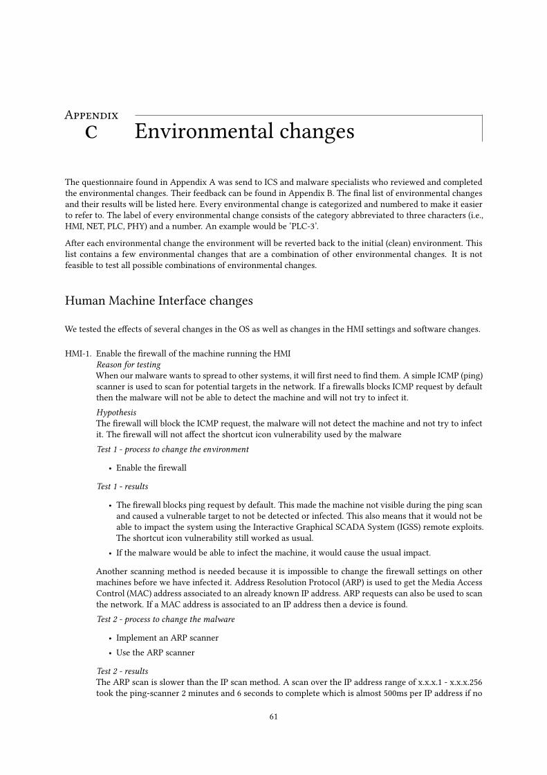
AppendixEnvironmental changesC
The questionnaire found in Appendix A was send to ICS and malware specialists who reviewed and completedthe environmental changes. Their feedback can be found in Appendix B. The final list of environmental changesand their results will be listed here. Every environmental change is categorized and numbered to make it easierto refer to. The label of every environmental change consists of the category abbreviated to three characters (i.e.,HMI, NET, PLC, PHY) and a number. An example would be ‘PLC-3’.
After each environmental change the environment will be reverted back to the initial (clean) environment. Thislist contains a few environmental changes that are a combination of other environmental changes. It is notfeasible to test all possible combinations of environmental changes.
Human Machine Interface changes
We tested the effects of several changes in the OS as well as changes in the HMI settings and software changes.
HMI-1. Enable the firewall of the machine running the HMIReason for testingWhen our malware wants to spread to other systems, it will first need to find them. A simple ICMP (ping)scanner is used to scan for potential targets in the network. If a firewalls blocks ICMP request by defaultthen the malware will not be able to detect the machine and will not try to infect it.HypothesisThe firewall will block the ICMP request, the malware will not detect the machine and not try to infectit. The firewall will not affect the shortcut icon vulnerability used by the malwareTest 1 - process to change the environment
• Enable the firewall
Test 1 - results
• The firewall blocks ping request by default. This made the machine not visible during the ping scanand caused a vulnerable target to not be detected or infected. This also means that it would not beable to impact the system using the Interactive Graphical SCADA System (IGSS) remote exploits.The shortcut icon vulnerability still worked as usual.
• If the malware would be able to infect the machine, it would cause the usual impact.
Another scanning method is needed because it is impossible to change the firewall settings on othermachines before we have infected it. Address Resolution Protocol (ARP) is used to get the Media AccessControl (MAC) address associated to an already known IP address. ARP requests can also be used to scanthe network. If a MAC address is associated to an IP address then a device is found.Test 2 - process to change the malware
• Implement an ARP scanner• Use the ARP scanner
Test 2 - resultsThe ARP scan is slower than the IP scan method. A scan over the IP address range of x.x.x.1 - x.x.x.256took the ping-scanner 2 minutes and 6 seconds to complete which is almost 500ms per IP address if no
61
Appendix C. Environmental changes
response is given and 1-2ms if a host responds. The ARP-scanner took 13 minutes and 9 seconds overthe same range before it was finished. This means it takes three seconds for the ARP-request to time outif no response received. The ARP-scanner is 6 times slower compared to the ping-scanner. The scannerscan be speeded by using multiple threads.
• This change did not influence the infection• This change did not influence the impact
Lessons learned/System knowledge neededDuring the first test we have found that ping is blocked by the firewall by default. If we want to use thisscanning method we need to know if firewalls are in place and which rules apply. We have implementedand tested another scanning method, based on ARP requests, that is not affected by the default firewallconfiguration. It would be unlikely that ARP requests are blocked. This would either hinder IP trafficfrom functioning or require static ARP entries. This makes the ARP scan more reliable than the pingscan.
HMI-2. Change the Operating System (OS) version on which the HMI runsReason for testingIGSS runs in our environment onWindowsXP SP3. This is an old operating system. It might be interestingto see how the malware reacts on a newer operating system. Note that IGSS does not run on Linux orMacOS based OSs, so our tests will only cover windows based systems.HypothesisThis change should not influence the exploits used according to their specifications.Test 1 - process to change the environment
• Set up a new Virtual Machine (VM) with Windows 7 Service Pack 0 (SP0)• Install IGSS
Test 1 - results
• The firewall in Windows 7SP0 blocks ping request by default. The firewall did not influence themalware when the ARP-scan was chosen as scan method. The shortcut icon vulnerability stillworked.
• This change did not influence the impact
Test 2 - process to change the environment
• Set up a new VM with Windows 7 Service Pack 1 (SP1)• Install IGSS
Test 2 - resultsWe encountered the same results as in test 1 with the exception that the shortcut icon vulnerability waspatched and therefore not useable.System knowledge neededIn the tests where we ran IGSS on newer OSs, i.e. Windows 7 SP0 and Windows 7 SP1, we noticed thatthe used OS affected the infection stage of the malware.
HMI-3. Change the IP address of the machineReason for testingIP addresses can be dynamically assigned. The infection process of the malware would likely fail ifthe IP address was hardcoded. That is why the malware uses a scanner. The scanner scans a range ofIP addresses for every network interface. The infected machine has two network interfaces, one forconnections to the Internet and one for the local subnet. The default scan range is from x.x.x.1 to x.x.x.20and this can be adjusted as needed.HypothesisAs long as the target’s IP address is in the scanner’s scan range, it would pose no problems to infectionor impact. The default IP address of the machine is 192.168.1.14.Test 1 - process to change the environment
62
Appendix C. Environmental changes
• Change the IP address to 192.168.1.20• Change the Local IP address in the used Modbus/TCP driver in System Configuration of IGSS.
Test 1 - results
• This change did not influence the infection• This change did not influence the impact
Test 2 - process to change the environment
• Change the IP address to 192.168.1.150• Change the local IP address in the used Modbus/TCP driver in System Configuration of IGSS.
Test 2 - results
• This IP address was not in the scanners range. No check was performed on the machine if it wasvulnerable and it attempt was made to infect it. It was still possible to infect the machine with aninfected USB drive.
• If the malware would be able to infect the machine, it would cause the usual impact
Test 3 - process to change the malware
• Set the scan range from x.x.x.1 to x.x.x.256.
Test 3 - resultsThe scan took 2 minutes and 6 seconds to complete. That is almost 500ms per IP address if no responseis given and 1-2ms if a host responds.
• This change did not influence the infection.• This change did not influence the impact.
Test 4 - process to change the environmentFor this environmental change we want to change the IP address of the HMI machine to an IP addressin the 10.x range. It is not possible to only change the HMI machine’s address because it would leave itunable to communicate with the PLC or any other machine. Therefore we also change the PLC and theinfected machine’s IP addresses.
• Change the PLC machine address to 10.11.12.13 .• Change the HMI machine address to 10.11.12.14 .• Change the infected machine address to 10.11.12.15 .• Change the IP address IGSS uses to communicate with the PLC.
Test 4 - results
• This change did not influence the infection.• This change did not influence the impact.
Lessons learned/System knowledge neededDuring this environmental change we learned that if an IP address is not in the range of the scanner, itwould also not be scanned. If it is in the range it would be scanned. The scan range can be determined atruntime by requesting the subnet-mask of the local machine and OR-ing it to obtain the network prefix.All underlying IP addresses should be scanned
HMI-4. Enable Data Execution Prevention (DEP)Reason for testingCertain parts of a program contain just data and no code. DEP is used to mark these parts of memory asnon-executable. This helps to prevent execution of data. DEP was introduced in Windows XP SP2 andDEP is only enabled for essential Windows programs and services by default.
63
Appendix C. Environmental changes
HypothesisThis should not affect the malware since our infection exploits are based on directory traversal vulnera-bilities and do not contain shellcode.Process to change the environment
• Turn on DEP for all programs and services
Results
• This change did not influence the infection• This change did not influence the impact
Lessons learned/System knowledge neededIn our case, the malware is not influenced by Data Execution Prevention (DEP).
HMI-5. Enable Address Space Layout Randomization (ASLR)Reason for testingAddress Space Layout Randomization (ASLR) is one of the security features provided by the OS. Itrandomizes address offsets of (e.g. stack, heap, libraries) in the process’s address space. This will make itharder to predict addresses that point to shellcode in the program.HypothesisThis should not affect the malware since our infection exploits are based on directory traversal vulnera-bilities.Background informationSince ASLR was not available in Windows XP and introduced in Windows Vista, it is not possible touse the default environment. The already set-up Windows 7 environment is used in this test. ASLR ison by default. However, this does not mean this test was cleared when Windows 7 was used as OS inenvironmental change HMI-2. Mark Russinovich’s Process Explorer shows that while IGSSmaster.exehas ASLR enabled, dc.exe and IGSSdataServer.exe are not ASLR-aware build, i.e., they are not build withthe /DYNAMICBASE linker flag.Test 1 - process to change the environment
• Use the Windows 7 machine with default ASLR settings
Test 1 - results
• This change did not influence the infection using the IGSS exploits.• This change did not influence the impact.
Test 2 - process to change the environment
• Use the previously setup Windows 7 environment.• Install Windows update 1 which enables forced ASLR settings.• Add forced ASLR entries for dc.exe and IGSSdataServer.exe to the register.
Test 2 - results
• IGSS could not start the dc.exe and IGSSdataServer.exe services. No supervision was possible.
As stated by Microsoft 1; forcing ASLR for a program with the registry-key MitigationOptions set to0x300 will prevent the program from loading if no reallocations are present.Lessons learned/System knowledge neededIn this case ASLR could not influence the exploits because the services did not support ASLR. If an exploitis affected by ASLR, a type of shellcode named an ‘egg-hunter’ can be used to work around ASLR.
1http://support.microsoft.com/kb/2639308/en-us
64
Appendix C. Environmental changes
HMI-6. Enable/Disable autoplay when a USB storage device is connectedReason for testingAutplay is a Windows feature that scans newly discovered media and performs an action / launches aprogram based on the contents. This environmental change will test the effect of autoplay on payloadPAY-1 (infection by USB drive).HypothesisWhen autoplay is set to ‘Open folder to view files using Windows Explorer’ then the malware is able torun without user interaction when the USB drive is inserted. The user has to open the infected folder ifAutoPlay is set to another value.Process to change the environment To set the autoplay functionality:
• For Windows 7:– Go to the Control Panel -> Hardware and Sound -> Autoplay .– Set the Mixed content value to ‘Open folder to view files using Windows Explorer’.
• For Windows XP:– When the USB stick is inserted a ‘Removable Disk’ window is opened, check ‘Always do the
Selected action’ and click ‘Open folder to view files using Windows Explorer’.
Results
• The malware was able to spread using the shortcut vulnerability without user-interaction if theUSB folder was automatically opened. Otherwise the user had to navigate to the infected foldermanually. The other infection method was unaffected.
• This change did not influence the impact.
Lessons learned/System knowledge neededThe autoplay functionality is not configured by default. If autoplay is set to ‘Open folder’, explorer willautomatically show the contents of the USB drive and the vulnerability would be executed. Otherwise itis up to the user to open the root folder of the infected drive. This is a plausible scenario since the userinserted the USB drive for a reason. It is also possible to automatically start malicious software in otherways using other techniques. A U3 USB stick can be used or a USB stick with a custom USB driver thatsimulates a keyboard can be used.
HMI-7. Change project paths used by HMIReason for testingPayload PAY-2 used to infect the IGSS HMI contains hardcoded paths that define where it copies itselfto and where it executes itself from. It copies itself to ‘C:\Documents and Settings\All Users\ApplicationData\7T’. If these are changed it might influence the infection processHypothesisThe IGSS copy exploit will place the malware in another folder. The IGSS execute exploit will not be ableto find the executable.Test 1 - process to change the environmentThe default project path is ‘C:\Documents and Settings\All Users\Application Data\7T\IGSS32\V9.0’.
• Copy the project from the default project path to the desktop• Make the default path inaccessible. We can do this by renaming the folder ‘7T’ in the default projectpath to ‘C:\Documents and Settings\All Users\Application Data\7T_renamed\IGSS32\V9.0’.
Test 1 - results
• The IGSS copy exploit created the folder ‘7T’ and placed the malware there. Infection proceededlike normal and succeeded.
• This change did not influence the impact
Test 2 - process to change the environment
65

Appendix C. Environmental changes
• Change to Windows 7SP1 because Windows 7 does not have the ‘C:\Documents and Settings’ path.
Test 2 - results
• The IGSS copy exploit placed the malware in the hidden folder ‘C:\ProgramData\7T’. Infectionproceeded like normal and succeeded.
• This change did not influence the impact.
Lessons learned/System knowledge neededThe exploits used did not require prior knowledge on system paths.
HMI-8. Increase/decrease HMI software update intervalsReason for testingThe HMI software’s update intervals indicate the time between each request to the PLC. A change in thetime interval could possibly influence the MITM payloads. The default scan interval is 1000ms.HypothesisThis will have no effect on infection or impact.Process to change the environment
• Scan intervals can be modified in IGSS during ‘Design Mode’ in ‘System Configuration’. After eachchange the HMI interface will have to be updated. This is done by opening the Definitions moduleand saving the project.– Change scan interval to 2,000ms– Change scan interval to 500ms– Change scan interval to 10,000ms
Results
• This change did not influence the infection• This change did not influence the impact
Lessons learned/System knowledge neededThe frequency of which the HMI requests updates did not influence the infection or impact stage.
HMI-9. Run the HMI software as unprivileged userReason for testingFunctionality which requires administrator privileges do not run under an unprivileged account. If themalware uses such functionality it might fail during the infection or impact stage.HypothesisOur malware is still able to perform the tasks as usual.Test 1 - process to change the environment
• Create a new account with limited privileges.• Copy the IGSS HMI project somewhere else because we can not alter the project used by theAdministrator.
• Open the project in IGSS.
Test 1 - results
• This change did not influence the infection• The malware ran a few seconds after the infection and then successfully exited. This was becauseit could not find the registry key used to check if IGSS was installed. We use an IGSS register thatstates that the current user has installed IGSS. The new account did not have the registry entry hasall IGSS registers except the installed register because another user installed IGSS. We should haveused another register for this check.
66
Appendix C. Environmental changes
Test 2 - process to change the malwareChange the malware to use another registry key to determine if IGSS is installed.Test 2 - results
• This change did not influence the infection• This change did not influence the impact
Lessons learned/System knowledge neededIn this case only unprivileged functionality was used by the malware. A privilege escalation exploit canbe used if administrator rights are needed.
HMI-10. Add a secondary hot backup serverReason for testingOur malware now infects one HMI. Only one malware instance attempts to impact the environment atany given time. If the control system consisted of two HMIs, two HMIs would be infected. Would themalware interfere with the other infection?HypothesisBoth machines will be infected. The created impact will depend on the payload. The payloads without aMITM will perform as usual. Payload PAY-7 that performs a MITM will not work.Test 1 - Process to change the environment
• Change the Station type to Station type to Server 1 in a Dualized System• Create a new station like current station with the same drivers, interfaces and nodes but set it toServer 2 in a Dualized System. Also set the IP address to the IP address that will be used for thesecondary machine.
• Clone the current HMI Virtual Machine• Change the IP address on the secondary machine• Change the MAC address on the secondary machine• Start Sync Server Configuration on the secondary machine• Start IGSS on the secondary machine and select Server 2 in a Dualized System as Station type
Test 1 - Results
• This change did not influence the infection. The malware infected both machines.• This change did not influence the impact. The PLC address was ARP spoofed twice so effectivelyall traffic was send to the machine that was the latest infected. The malware on each machineresponded only to their own HMI and filtered out the traffic of the other HMI.
Test 2 - Process to change the environmentThis test determines how the malware reacts if it is unable to infect one of the two HMIs.
• Modify the malware so that it does not infect the second HMI by hardcoding its address in it.
Test 2 - Results
• This malware only infected one HMI.• This change did not influence the impact. When PLC address was ARP-spoofed all traffic from bothHMIs was send to the infected HMI. The malware on the infected HMI only responded to its ownHMI and filtered out the traffic of the other HMI. The first HMI did not notice anything different butthe other HMI did not receive any responses from the PLC since it send the request to the infectedHMI and the malware did not respond. The second HMI gave a communication problem warningbut it could not reconnect.
67
Appendix C. Environmental changes
Lessons learned/System knowledge neededThe amount of HMI only affected the MITM payloads, so the lessons we’ve learned are mainly about them.If the malware can infect all HMIs, then the impact phase of a MITM attack should start synchronouslyacross multiple machines that supervise a specific part. If the malware can not infect all HMIs but cancommunicate with them and spoof their ARP cache, it can still perform a MITM attack. It only needs torespond to their requests. This would mean that it should change its filter and optionally enumerate theaffected HMIs at runtime. Otherwise; the HMIs the malware can not infect and communicate with, willbe able to read the true state of the PLC or possibly be used to intervene.
HMI-11. Two single user supervisory and control machines (Report to two HMIs)Reason for testingThis test looks a lot like environmental change HMI-10, but the machines are running totally separate. Itis also possible to let the second single user machine only supervise part of the plant.HypothesisThis environmental change will lead to the same results as in environmental change HMI-10.Process to change the environment
• Change the Station type to Single user• Clone the current HMI Virtual Machine• Change the IP address on the secondary machine• Change the MAC address on the secondary machine• Start IGSS on the secondary machine
Results
• This change did not influence the infection• This change did influence the impact. The second machine was infected a second later than thefirst. The malware on the second machine started spoofing responses after the malware on thefirst machine performed the first action, i.e., opening the in-valve. This means the HMI on thesecond machine showed this action. As with the last environmental change the PLC address wasARP-spoofed twice so effectively all traffic was send to the machine that was the latest infected.The malware on each machine responded to their HMI.
Lessons learned/System knowledge neededSame as in environmental change HMI-10.
HMI-12. When multiple PLCs are used, make each HMI supervise only part of the PLCsReason for testingThis environmental change tests how the malware responds to the scenario where it can only influencean unknown part of the setup. This environmental change also contains changes from PLC-1 ‘Usedregister addresses’, HMI-11 ‘Two supervisory and control machines’ and PLC-7 ‘use multiple PLCs’.HypothesisThe malware will infect both HMIs and infect and impact the system as usual.Process to change the environment
• Use the environment created during the ‘two single user supervisory and control system’ HMI-11environmental changes.
• Delete from HMI 1 the left half of the system (i.e., drum 2, pump 2, drum 3, pump 3 and out valve)since it will only supervise the right half. See Figure C.1.
• Delete from HMI 2 the right half of the system (i.e., drum 1, pump 1, drum 4, pump 4 and in valve)because it will only supervise the left half.
• Configure each of the drum and pump to a PLC like in environmental change PLC-7 ‘Change numberof PLCs’.
Results
68

Appendix C. Environmental changes
Pump 2
Pump 3
In-valveOut-valveDrum 1Drum 2
Drum 3 Drum 4
Pump 1
Pump 4
HMI 1 HMI 2
PLC2
PLC3
PLC1
PLC4
Figure C.1: Chemical plant where two HMIs supervise two PLCs each
• This change did not influence the infection• The malware is able to write either the highest or lowest recorded value to each writable PLCregister. It is not possible to define the impact on the ICS in advance because the state created bythe malware is random.
Lessons learned/System knowledge neededThe malware behaved the same as in environmental changes PLC-7 and HMI-11 combined and had thesame result as mentioned in those environmental changes PLC-7 and HMI-11.
HMI-13. Have two channels open with the PLCsReason for testingIn this environmental change two connections will be opened between the HMI and the PLC; one nor-mal connection and one backup connection. The backup connection will be used in case the normalconnection does not respond.HypothesisIf both connections use the same network, the malware will perform as usual. But if both connectionsdo not use the same network, the malware will not be able to disconnect the second connection betweenthe HMI and PLC, giving the HMI a way to detect the MITM attack. All other payloads will perform asusual.Process to change the environment / ResultsThe current HMI software does not support backup connections to the PLC. It is therefor not possible totest this environmental change.
HMI-14. Uninstall winpcap from the HMIReason for testingWireshark and winpcap were installed for debugging purposes. As discussed in environmental change3.4.3, C does not support raw TCP sockets. Winpcap is used as an alternative to spoof packets.HypothesisIf the malware does not have a way to spoof packets, it will not be able to perform MITM attacks. Allother functionality will still work.Test 1 - process to change the environment
69
Appendix C. Environmental changes
• uninstall winpcap
Test 1 - results
• This change did not influence the infection
• The malware did not know winpcap was not installed and could not be used to spoof packets. Itdecided to use the default payloads; PAY-7 with PAY-3 to overflow the drums while performinga MITM attack. When the malware requested all network interfaces from winpcap, the winpcapcall returned an error and the malware decided to quit. MITM payloads PAY-6 and PAY-7 stoppedworking. The malware did not impact the environment.
Test 2 - process to change the malware
• implement a check to see if winpcap is installed
• if winpcap is not installed, use payload PAY-3 without MITM attack.
Test 2 - results
• This change did not influence the infection.
• Payloads PAY-3, PAY-4, PAY-5 and PAY-8 worked as usual.
Lessons learned/System knowledge neededIf the malware is not able to create raw sockets or use similar functionality, it is not possible to spooftraffic. Other payloads were not affected.
HMI-15. Isolate the HMI from the Internet or external accessReason for testingIf the HMI is isolated or air-gapped from the outside then it would become hard, or nearly impossibleto infect it. Isolating the HMI would mean the operational technology of the plant would be air-gappedwith the outside world.
HypothesisThe malware is not able to exploit the HMI and thus not impact the control system.
Process to change the environment
• Use the VirtualBox Network Manager to isolate the machine running the HMI from any othernetwork except the control system network. Only the HMI and the PLC can be connected to thiscontrol system network. This way the plant is not connected to the outside world.
Results
• The malware was not able to detect any other machines and thus was not able infect the HMI. If aUSB drive is available to the infected machine when the malware was running, it will be infected.It can infect the plant only if this infected USB drive was transported past the air-gap, and insertedin a machine at the plant. This does not have to be the machine running the HMI, but can also be amachine connected to it.
• Since the malware did not infect the plant, it could not impact it.
Lessons learned/System knowledge neededIf the plant is air-gapped, it is hard to infect it. The malware would have to physically travel past theair-gap on a storage device. This would require physical access to the plant and to a machine inside theplant. It would likely be impossible to create a backdoor to send information to a Command and Controlserver.
70

Appendix C. Environmental changes
Network changes
For these environmental changes, we changed the network properties and send noise and other traffic over thenetwork to determine if it affected the malware
NET-1. Add simulated trafficReason for testingThis test will determine if the malware is affected by latencies or delays.HypothesisThis change will not affect the capability of the malware to infect or impact.Process to change the environmentA script sends random traffic from the infected machine to the HMI and from the HMI to the PLC.
• Download netcat for windows. Netcat allows us to read from and write to network connectionsusing TCP or UDP.
• Download Zero and Random device driver 2 which emulate ‘/dev/zero’ and ‘/dev/random’ in *nixlike environments. This will be used to discard data and generate random data from the commandline.
• The following command;nc.exe -Lvvup 1234 > nulcan be used to receive traffic from port 1234 and throw it away. Andtype \\.\random\ | nc.exe -vvu targetip 1234can be used to send random traffic to a target on port 1234.One connection can generate around 3Mbps of traffic. To create multiple connections we can use afor loop. The following for loops are supposed to be one line but since it does not fit on one line,two lines are used.
for /L \%i in (1234,1,1240) do@start "Receive on %i" "cmd.exe" "/c nc.exe -Lvvup %i > nul"
can be used to listen on ports 1234 to 1240. And the command
for /L %i in (1234,1,1240) do@start "Send to %i" "cmd.exe" "/c type \\.\random\ | nc -vvu targetip %i"
can be used to send random traffic to a target on ports 1234 to 1240.• Use these commands to send random traffic from the infected machine to the HMI.
ResultsFor this test we generated around 55Mbps of traffic with loop parameters (1234,1,1250). On asidenote; both sender and receiver had a high CPU load.
• This change did not influence the infection• This change did not influence the impact
Lessons learned/System knowledge neededOther random traffic does not have influence on the malware.
NET-2. Instable network connectionReason for testingSince it is not possible to introduce noise on the Virtualbox virtual network, we’ll try to simulate a verybusy Local Area Network (LAN) with 100% network utilization. We will use the same method as in theprevious environmental change, NET-1.
2http://www.ltr-data.se/opencode.html/#ZeroDrv
71
Appendix C. Environmental changes
HypothesisThe malware spreads ‘slower’ and it will take longer during the infection phase. This way of networksimulation will also create a 100% CPU load on both sender and receiver.Process to change the environment
• Assign three CPU cores to the HMI machine• Assign two CPU cores to the infected machine• Perform the same steps described in environmental changeNET-1with loop parameters(1234,1,1290)
ResultsA 99% network utilization was created on the 100Mbps connection between the infected machine and theHMI machine. The generation of random numbers took quite some CPU time on the sender’s machine.This resulted in a 100% CPU load on the sender’s machine. The receiving machine also had a 100% CPUload because a lot of processed were created and this resulted in a lot of interrupts.
• This change did influence the infection speed. Every step of the process took at least two or threetimes longer but the functionality remained the same. The malware did infect the HMI.
• This change did influence the speed and latency of which it started the payload.
Lessons learned/System knowledge neededA 99% network utilization and a 100% CPU load did slow the malware down but did not limit its function-ality.
NET-3. Introduce traffic from a legitimate sourceReason for testingIn this environmental change network traffic from a legitimate source was added. The only legitimateICS type of network traffic we’re able to create at this moment is the traffic between two HMI servers.HypothesisThis will not reduce the impact of the malware.Process to change the environmentIn environmental change HMI-10 a secondary hot backup server was added. A primary and a secondaryserver are able to synchronized project data on port 12397. This port is also used by the malware.
• Add a secondary hot backup server.• Start SyncSrvCfg.exe to synchronize between both servers. This service will communicate with theprimary HMI machine on port 12397.
Results
• This change did not influence the infection.• This change did not influence the impact.
Lessons learned/System knowledge neededIntroducing legitimate traffic did not reduce the impact of the malware.
NET-4. Replay some previously captured trafficReason for testingIn this environmental change we test if other traffic, including Modbus traffic interferes with the malware.HypothesisIt will not affect the malware.Process to change the environmentIn this test network traffic will be replayed while our malware tries to infect and impact the system. Thisrequires a recorded network traffic file. The MITM payloads where able to spoof traffic for over an hour.During this tests we recorded the traffic with Wireshark in a .pcapng file. We use the recorded traffic filefrom the RESULT-7. test.
72
Appendix C. Environmental changes
• Set up a Linux based virtual machine, for example Kali.• Connect it to the virtual network.• Use tcpreplay: tcpreplay –intf1=eth0 -x=2.0 recordedtraffic.pcapng
Results
• This change did not influence the infection.• This change did not influence the impact.
Lessons learned/System knowledge neededThe malware filters traffic on IP addresses and ports. It was important here to set the filters correctlybecause the malware could respond to the replayed traffic otherwise. The ports used in the recordedtraffic file where not the same because IGSS uses a random port every time it starts. This way the malwareignored all replayed traffic.
NET-5. Put the control system in another VLANReason for testingThis environmental change looks a lot like environmental change HMI-15. The difference is that environ-mental change HMI-15 separates the infected machine from the plant physically while this environmentalchange only separates the infected machine from the plant logically.HypothesisThe same outcome as in environmental change HMI-15 since it does not matter how the plant is separatedfrom the infected machine.Process to change the environment
• Use the VirtualBox Network Manager to isolate the HMI from the infected machine by placing theHMI and the PLC machine on another network that is not connected to the network containing theinfected machine. This way the HMI and the PLC are not connected to the infected machine.
Results Same as in environmental change HMI-15.Lessons learned/System knowledge neededThe lessons learned are the same as in environmental change HMI-15 since it did not matter to themalware how the plant was separated from the outside world (physically or logically).
PLC configuration changes
The environmental changes are based on adjusting settings of the PLC.
PLC-1. Change the register addresses used by the PLCReason for testingThe register addresses of the sensors and actuators are hardcoded in the malware. The malware knowswhich addresses are associated with the actuators. If we change the addresses used by the sensors andactuators, then the malware will still use the old addresses. If the malware writes to the wrong addresses(i.e., the addresses not used by actuators) then the physical process(es) will not be affected. This would,for example, mean that the malware would be unable to overflow or empty the drums.HypothesisThe malware will be able to spread to the HMI machine but the impact will be different if all registeraddresses are changed, then the malware will manipulate the wrong register addresses. This implies thatthe malware is unable to manipulate actuators and thus target the integrity of the processes. It will stillbe possible to attack the availability (payload PAY-8 will still succeed).Test 1 - process to change the environment
• Change the PLC simulation script to use the same addresses, but with an offset of 1000.
73
Appendix C. Environmental changes
• Change the HMI project definition to use the new addresses.
Test 1 - results
• This change did not influence the infection.• The malware was able to compromise the supervision capabilities of the HMI using the MITMpayloads but was unable to manipulate the actuators. The malware could still target availability byterminating the HMI process repeatedly with payload PAY-8.
Test 2 - process to change the malwareWe will test if the malware can adapt to register changes by maturing it and without introducing newknowledge. We developed functionality that analyzes the environment for a specified time. With thisinformation we can create an impact on the integrity of the environment. The malware will analyze theenvironment until it has analyzed a predefined number of packets.
• When the HMI is infected, the first step would be to listen to every connected PLC. The malwareallocates and initializes the variables that are used to analyze the traffic.
• The malware analyzes the traffic. It looks at the memory registers that have been written and theminimum and maximum values that are read. Finally, it records a response packet which will beused later to spoof responses.
• The malware writes to every writeable memory register either its minimum or maximum recordedvalue.
Test 2 - results
• This change did not influence the infection.• The malware is able to write either the highest or lowest recorded value to each writeable PLCregister. It is not possible to define the impact on the ICS in advance, because the state created bythe malware is random.
Lessons learned/System knowledge neededIf we do not know what registers are used to read from and write to, we need to analyse the traffic orwrite to all addresses. During the tests, we analyzed the traffic between the PLC and HMI and determinedwhich values were needed to be spoofed and which addresses were connected to actuators.The impact phase relied on the assumption that the smallest or largest values are potentially the mostdangerous values for actuators. With the knowledge gained from analyzing the packets during runtimewe were able to create a random potentially dangerous state. Another similar possible implementationcould be to write random, zeros or maximum values to the PLC. An increased probability to create impactcan be achieved if we know that larger values are more/less likely to create impact than small values.More consistent results are created when the registers are set to the highest recorded value.The malware analyzed the traffic when the PLC communicated to the HMI through Modbus/TCP. Themalware might not be able to analyze the traffic, if the traffic is encrypted or when another protocol orinterface is used. We can not determine the possibilities for the other cases yet. We determine if it is alsopossible to analyse serial connection traffic when we connect the PLC to the HMI with a serial connectionin environmental change PLC-5.
PLC-2. Change the IP addressReason for testingIf the IP address of the PLC was hardcoded it could prevent the payload from executing. When themalware wants to determine the IP address of the PLC it will listen to all TCP/IP traffic between thecurrent machine and port 502 of another machine. It uses a filter to block out all other network traffic.It saves the connection information like the port, IP address and MAC of the source and destination in a‘connection’ struct.HypothesisBoth infection and impact will execute as usual.Test 1 - process to change the environment
74
Appendix C. Environmental changes
• Change the IP address the PLC listens to 192.168.1.196 .• Change the IP address IGSS uses to communicate with the PLC.
Test 1 - results
• This change did not influence the infection.• This change did not influence the impact.
Test 2 - process to change the environment and resultsThe environmental change to test IP addresses to an address in the range of 10.x has been described inenvironmental change HMI-3 in test 3.Lessons learned/System knowledge neededThe supervisory software interacts with the PLC. If we know the process that is responsible for commu-nication with the PLC it is possible to get communication details like IP addresses and ports with thenetstat command.
PLC-3. Change the portReason for testingThe default Modbus port is 502. When the malware tries to determine the IP address of the PLC it willlisten to traffic destined for port 502. All other traffic is filtered out. This filter will likely influence themalware when a non-standard port is used.HypothesisInfection will proceed a usual but it will not be able to find a PLC and thus not impact the environment.Test 1 - process to change the environment
• Change the port the PLC listens to (port 507).• Change the port IGSS uses to communicate with the PLC.
Test 1 - results
• This change did not influence the infection.• No PLC was found and therefor the malware could not communicate with the PLC to impact theenvironment. Payload PAY-8 was not affected.
Test 2 - process to change the malware
• Change the filter used by the malware so that it does not filter traffic on port 502. The only filterremaining filters on TCP/IP traffic.
Test 2 - results
• This change did not influence the infection.• This change did not influence the impact.
Lessons learned/System knowledge neededIt is convenient if port 502 is used for Modbus traffic, but this information can be gathered during runtime.In environmental change PLC-7 we discuss other possibilities to enumerate connected PLCs at runtime.
PLC-4. Change response latencyReason for testingThe malware might be sensitive to late responses from the PLC. The standard latency of the PLC can beset to a value between 0 and 10000ms and is set to 100ms in our default setup.HypothesisThis change will not affect the capability of the malware to infect or impact.Process to change the environment
• Change the PLC responsiveness to:
75
Appendix C. Environmental changes
– 0ms latency– 20ms latency– 50ms latency– 500ms latency– 3,000ms latency– 10,000ms latency
Results
• This change did not influence the infection• This change did not influence the impact of any payload except for payload IV with the MITM type1 attack that simply tries to respond faster than the PLC. Delays larger than ~20ms were no problem,but delays smaller proved to be too fast for the malware to respond. This delay might be due to theCPU-scheduler, scheduling the malware after the HMI software. As said before; all other payloads,including the other MITM, worked fine.
Lessons learned/System knowledge neededWe did not see any differences in the malware’s behavior during the change of the response delay.
PLC-5. Use Modbus over RS232 instead of TCP/IPReason for testingThe malware has no build in support for the RS232 interface (serial port).HypothesisThe malware is not able to find any connections to PLCs. It will just exit without trying to cause animpact. If support is added, it will not be able to communicate to the PLC since the HMI software isalready connected to the serial port.Test 1 - process to change the environment
• Add a serial interface (COM1) between the HMI machine and the PLC machine.• Set the PLC simulator to use Modbus over RS232 on port COM1 with a baud rate of 19200, Parity‘Even’, 8 data bits, 1 stop bit and RTS control to ‘Enable’.
• Open the System configuration module in the HMI software. Add a new ‘Modicon Modbus protocol’driver. Configure this driver to connect to COM1 with the same settings as the PLC. Add a nodeand set the node number to 1.
• Open the Definitions module and set every sensor and actuator to use the new driver and node 1.
Test 1 - results
• This change did not influence the infection.• The malware was not able to find any connected PLC and did not impact the system. Payload PAY-8still worked.
Test 2 - process to change the malwareThe malware should be able to connect and communicate with a PLC over RS232 using Modbus.
• Add functionality to list all available serial ports.• Add functionality to determine the port that is used by the HMI software.• Add functionality to use Modbus over serial port.
Test 2 - results
• This change did not influence the infection.• The malware was not able to connect to the serial port when the HMI software was running.
Test 3 - process to change the malwareA connection should be made even when the HMI software runs.
76

Appendix C. Environmental changes
• The malware should be able to terminate the processes that communicate over the serial port. Theprocesses that connect to the PLC are 7tdrv.ex and dc.exe.
Test 3 - results
• This change did not influence the infection.• The malware was able to connect to the serial port and communicate with the PLC to overflowthe drums. Since the malware did not release the serial port connection, it left the HMI unable toreconnect. If the HMI software can not reconnect to the serial port after a few, probably one ortwo, tries it will stop trying and give a warning on the initial ‘welcome’/‘configuration’ screen. It islikely that this screen is not visible but the HMI is shown instead because this screen can be used tosupervise and control the processes. The HMI does not give any warning/alarm. This means thatwhen the HMI screen is shown, the only way to see the connection loss would be to see a smallchange in the IGSS icon in the taskbar. The HMI will show the last remembered state during theattack until the supervision capabilities of the HMI are restarted. This is a Denial of Service (DoS)attack since it is not possible to communicate with the PLC or modify its registers.
Test 4 - process to change the malwareThis test is to determine if there is a way to keep both HMI software and the malware connected to thesame PLC without either of them giving warnings.
• Change the malware to write a harmful state to the PLC in a loop. Start this loop by terminatingthe supervisory processes that communicate with the PLC over the serial port, connect to the PLCover this serial port and write the harmful state. The final steps would be to close the connectionand sleep for five seconds.
Test 4 - results
• This change did not influence the infection• By closing the serial port every time after user we allow the HMI software to restart the communi-cation services and reconnect to the PLC over the serial port. This way both software and malwarecan use the same serial connection. The HMI software will give no warnings or errors. The HMI isable to show the values from the PLC and modify registers although it is not very responsive. It isnot very responsive because it only updates in a short time span and when the HMI is outdated it isnot possible to modify actuators. The HMI can be used to manipulate the PLC registers to delay theimpact of the malware but since this functionality is only available for a short period of time, it isnot possible to completely protect from it.
Lessons learned/System knowledge neededIt is possible to connect to the PLC and keep the HMI working without errors or warnings. Modbus overRS232 supports two transition modes; RTU and ASCII. This affects the number of bits per byte and codingsystem. The baud rate is also required to communicate with the PLC but does not have to be known inadvance. According to the Modbus specification [19] the baud rates 9600 bps and 19.2 Kbps are requiredto implement and 19.2 Kbps is the required default. The number of possible baud rates is also limitedand it is possible to try and guess the correct baud rate in a limited number of tries. The node id canbe determined by requesting information from the PLC. Knowledge about the environment is needed inadvance since it is not possible to have a serial port opened twice without installing new drivers, changingsettings or physically changing cables. We can analyze the state of the PLC over a period of time with thesame mechanism as we use to write to the PLC. First disconnect the HMI from the serial port, connect tothe serial port, read the PLC state and then close the connection to give the HMI a chance to connect. Wecan not sniff the write messages performed by the HMI because these can only happen when the HMI isconnected.
PLC-6. Change protocol to DF-1This protocol uses the serial port as the previous environmental change (PLC-5) where Modbus is used asprotocol. The difference between the two environmental changes is the protocol. No implementation ofthe DF-1 in C is available for Windows based systems. It would be possible to develop the DF-1 protocol
77
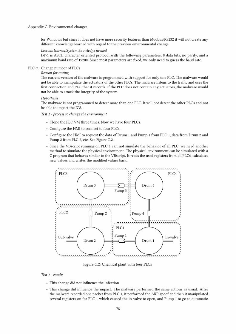
Appendix C. Environmental changes
for Windows but since it does not have more security features than Modbus/RS232 it will not create anydifferent knowledge learned with regard to the previous environmental change.Lessons learned/System knowledge neededDF-1 is ASCII character oriented protocol with the following parameters; 8 data bits, no parity, and amaximum baud rate of 19200. Since most parameters are fixed, we only need to guess the baud rate.
PLC-7. Change number of PLCsReason for testingThe current version of the malware is programmed with support for only one PLC. The malware wouldnot be able to manipulate the actuators of the other PLCs. The malware listens to the traffic and uses thefirst connection and PLC that it records. If the PLC does not contain any actuators, the malware wouldnot be able to attack the integrity of the system.HypothesisThe malware is not programmed to detect more than one PLC. It will not detect the other PLCs and notbe able to impact the ICS.Test 1 - process to change the environment
• Clone the PLC VM three times. Now we have four PLCs.• Configure the HMI to connect to four PLCs.• Configure the HMI to request the data of Drum 1 and Pump 1 from PLC 1, data from Drum 2 andPump 2 from PLC 2, etc. See Figure C.2.
• Since the VBscript running on PLC 1 can not simulate the behavior of all PLC, we need anothermethod to simulate the physical environment. The physical environment can be simulated with aC program that behaves similar to the VBscript. It reads the used registers from all PLCs, calculatesnew values and writes the modified values back.
Pump 2
Pump 3
In-valveOut-valveDrum 1Drum 2
Drum 3 Drum 4
Pump 1
Pump 4PLC2
PLC1
PLC3 PLC4
Figure C.2: Chemical plant with four PLCs
Test 1 - results
• This change did not influence the infection• This change did influence the impact. The malware performed the same actions as usual. Afterthe malware recorded one packet from PLC 1, it performed the ARP-spoof and then it manipulatedseveral registers on for PLC 1 which caused the in-valve to open, and Pump 1 to go to automatic.
78
Appendix C. Environmental changes
The states of the other pumps and valve remained unchanged. The result was that drum 1 and 2were filled and eventually overflowed.
The result of the test was more luck than wisdom because the first PLC contained an important valve, e.g.,the in-valve, the addresses of the in-valve and pump 1 where the same and the malware had knowledgeabout how the valves and pumps worked. The goal now would be to change the malware so it would notuse this information any more.Test 2 - process to change the malwareWe will change the malware so that it identifies all PLCs, analyzes the traffic and finally interact with theactuators while it performs a MITM attack.
• The first step would be to identify the connections to the PLCs. This can be done in several ways,three of those are: we can search through the HMI software’s project files to look for connectionsand properties. The second way is to sniff traffic to find out which connections are established to thedefault Modbus port. Another way is to list all connections established by the HMI’s communicationdriver (with the netstat command). The first options needs to know which HMI system softwareis running and takes more time to define for multiple HMI software packages. The second optionassumes that a specific protocol is used on the default port for all PLCs while the third option needsto know the name of the HMI’s driver. The last option would only needs the name of the servicethat communicates with the PLCs and it is possible to predefine several options for several HMIsoftware packages that can be tested at runtime with the same accuracy. The last option is chosento implement.
• The next step would be to listen to every connection to allocate memory and initialize the variablesand buffers we use to analyze the traffic.
• To analyze the traffic we record the memory registers that have been written to and the minimumand maximum values of the next n samples. Finally we record a response packet for each request.These responses will be used to spoof responses after the ARP-spoof.
• Modify the ARP-spoof functionality so it sends ARP packages to all PLCs.• Modify the response part so it uses the recorded packets to respond to each corresponding PLC.• Add functionality to send to each PLC for every writable memory register either its minimum ormaximum recorded value.
Test 2 - results
• The infection part worked as usual• The malware behaved as it should; it identified all PLCs, analyzed the traffic, wrote to the PLCsand performed the ARP spoof. The result was that the C program, that simulated the physicalenvironment, could not communicate to the other PLCs any more and was therefor unable tosimulate the physical environment.
Test 3 - process to change the environmentWe now need to modify the environment and physical environment simulation program so that it willkeep functioning during the attack.
• create a new local network for the sole purpose of simulating the physical environment.• connect it to the machines that simulate the PLCs and assign a unique IP address to every machine.• modify the physical environment simulation program to use the new IP addresses. Now it will notbe affected any more by the ARP spoof.
Test 3 - results
• This change did not influence the infection.• Themalware is able to write either the highest or lowest recorded value to each writable PLC register.It is not possible to define the impact on the ICS in advance because the state created by the malwareis random.
79
Appendix C. Environmental changes
Lessons learned/System knowledge neededDuring this test we needed a way to identify the connections between the HMI and PLCs. We can get alist of all connections if we know something about the IP addresses or ports in advance or if we know theprocess name that communicates with the PLCs.The same lessons as in environmental change PLC-1 ‘PLC change register address’ test are applicablehere; in this environmental change we also analyzed the network traffic and created a random potentiallydangerous state.
Physical process changes
When we tested how changes in the physical environment affected the malware, we mostly changed the workingsor the quantity of the sensors and actuators in the environment.
PHY-1. Change number of pumpsReason for testingThe number of pumps is hardcoded in the malware. We test if the amount of pumps influence the malware.HypothesisThe malware will ignore the fifth pump and create the same impact as before. The analysis functionalitydeveloped during environmental change PLC-1 ‘Change memory addresses used’ will enable the malwareto create a random potentially dangerous system state.Test 1 - process to change the environment
• Open the Definition module where the HMI can be changed.• Add a new pump, name it ‘Pump_5’ and add pipes to visually connect the pump from Drum 1 toDrum 3.
• Update the physical environment simulation script to support the fifth pump.
Test 1 - results
• This change did not influence the infection• This change did not influence the impact
Test 2 - process to change the malware
• Use the analysis functionality developed in environmental change PLC-1 ‘Changememory addressesused’.
Test 2 - results
• This change did not influence the infection• The malware is able to write either the highest or lowest recorded value to each writable PLCregister. It is not possible to define the impact on the ICS in advance because the state created bythe malware is random.
Test 3 - process to change the environment
• Remove Pump 2
Test 3 - results
• This change did not influence the infection• Same impact as in the previous two tests
80
Appendix C. Environmental changes
Lessons learned/System knowledge neededThe amount of pumps did not have influence on the malware. If the in-valve is open and the out-valve isclosed, the total amount of chemicals in the system will increase and (at least) one drum will overfloweventually. The same holds for the case if the in-valve is closed and the out-valve is opened; the totalamount of chemicals in the system decreases and at least one drum will eventually be empty.
PHY-2. Change number of drumsReason for testingThe number of drums is hardcoded in the malware. We will test if a change in the number of drums canreduce or diminish the effect of the malware.HypothesisThe malware will not be influenced by the number of drums.Test 1 - process to change the environment If we add a drum, it would make sense to also add a connectionbetween the newly added drum and the other drums. To connect the new drum to the other drums, pipesand a pump are added.
• Open the Definition module where the HMI can be changed.• Add a new drum, name it ‘Drum_5’ and add a pump and pipes to connect the drum to from Drum 4and Drum 1. Now we have a circle of five drums instead of four.
• Update the physical environment simulation script to support the fifth drum and pump.
Test 1 - results
• This change did not influence the infection• This change did not influence the impact
Test 2 - process to change the environment
• Start from the clean environment (where we have four drums).• Remove Drum 4. Now we have three drums.
Test 2 - results
• This change did not influence the infection• This change did not influence the impact
Lessons learned/System knowledge neededThe malware does not need to know how many drums are present in the plant. If a drum is added, itsstate will also be spoofed during the MITM attack.
PHY-3. Change number of in- or out-valvesReason for testingThe malware is able to overflow the system by putting the opening the in-valve and the closing theout-valve. The state of the other actuators is of minor importance. If the total amount of chemicals in thesystem increases, it will overflow eventually.HypothesisThe malware is able to impact the system in the same way as before. If an attack, intended to overflowall drums, is detected it can be prevented by opening the second out-valve. This will create a balancebetween the amount of chemicals flowing in and out. This way the malware will not be able to overflowthe drums any more. A similar scenario holds when a second in-valve is present and the malware wantsto empty all drums.Test 1 - process to change the environment
• Open the Definition module where the HMI can be changed.• Add a new valve and add pipes to visually connect the valve to Drum 3.• Update the physical environment simulation script to support the second out-valve.
81
Appendix C. Environmental changes
Test 1 - results
• This change did not influence the infection• This change did not influence the impact if the attack was not detected. If it was detected and itwas an overflow-type attack, it could be prevented by opening the second out-valve. However; theactuators, including the second out-valve, can not be manipulated from the infected HMI.
Test 2 - process to change the malware
• Use the analysis functionality developed in environmental change PLC-1 ‘Changememory addressesused’.
Test 2 - results
• This change did not influence the infection• The malware is able to write either the highest or lowest recorded value to each writable PLCregister. It is not possible to define the impact on the ICS in advance because the state created bythe malware is random.
Test 3 - process to change the environment
• Open the Definition module where the HMI can be changed.• Add a new valve and add pipes to visually connect the valve to Drum 4.• Update the physical environment simulation script to support the second in-valve.
Test 3 - resultsIn this test we use the unmodified malware that uses hardcoded values.
• This change did not influence the infection• This change did not influence the impact if the attack was not detected. If it was detected and itwas an empty-type attack, it could be prevented by opening the second in-valve. However; theactuators, including the second in-valve, can not be manipulated from the infected HMI.
test 4 - process to change the malware
• Use the analysis functionality developed in environmental change PLC-1 ‘Changememory addressesused’.
Test 4 - results
• This change did not influence the infection• The malware is able to write either the highest or lowest recorded value to each writable PLCregister. It is not possible to define the impact on the ICS in advance because the state created bythe malware is random.
If the in- or out-valve is removed from the initial setting it would make the system lose critical function-ality. Therefor these tests are not performed.Lessons learned/System knowledge neededIt can be crucial for a predefined attack to have knowledge of all important actuators. The malware canuse a scanner to determine which actuators are available
PHY-4. Change amount of liquid drums can holdReason for testingThis test determines if the malware depends on maximum liquid levels.HypothesisThis will not influence the malware but it will influence the time it takes to fill and overflow the drumssince the flow speed of the liquids is still the same.Process to change the environment
82
Appendix C. Environmental changes
• Open the Definition module where the HMI can be changed.• Define for every drum the maximum liquid level to 250 and set the alarms and warnings accordingly.• Update the physical environment simulation script so that drums can hold up to 250 liquid.
Results
• This change did not influence the infection• This change did not influence the impact
Lessons learned/System knowledge neededThe amount of liquid a drum can hold is not important to know in advance. The amount of liquid a drumcan contain only affects the time it takes to put the system in a critical state.
PHY-5. Change working of the pumpsReason for testingThe values of the settings of the pumps are hardcoded in the initial version of the malware. The defaultsettings of the pump are 0 for Auto, 1 for Off and 2 for On. If this is different in the physical environmentthen the malware can put a pump in a different state than intended.HypothesisThe malware will write the same values as before to the pumps.Test 1 - process to change the environment
• Update the physical environment simulation script with the following settings:– Assign 0 to ‘Off’ (0 is by default ‘Auto’)– Assign 1 to ‘On’ (1 is by default ‘Off’)– Assign 2 to ‘Auto’ (2 is by default ‘On’)
Test 1 - results
• This change did not influence the infection• The malware tries to overflow the drums and sets most pumps now to ‘Off’ instead of ‘Auto’ andPump 4 to ‘On’ instead of ‘Off’. This resulted in Drum 1 overflowing and Drum 4 being emptied.
Test 2 - process to change the malware
• Use payload PAY-4 ‘empty all drums’.
Test 2 - results
• This change did not influence the infection• The malware tries to empty all drums and sets most pumps now to ‘Auto’ instead of ‘On’ and Pump2 to ‘On’ instead of ‘Off’. This resulted in Drum 2 being emptied at a fast rate while the other drumsmore or less kept their liquid levels.
Test 3 - process to change the malware
• Use the analysis functionality developed in environmental change PLC-1 ‘Changememory addressesused’.
Test 3 - results
• This change did not influence the infection• The malware is able to write either the highest or lowest recorded value to each writable PLCregister. It is not possible to define the impact on the ICS in advance because the state created bythe malware is random.
83

Appendix C. Environmental changes
Lessons learned/System knowledge neededThe valves are also used to create an impact and if the malware can use the pumps correctly it canoptimize the impact. For instance, if we want to empty a drum we can open the out-valve but if we wantto empty all drums we would have to enable the pumps. Although it is not necessary to know how theactuators work, it is very convenient to know. Without this knowledge we would have to analyze andguess the potentially harmful state of each actuator and thus decreasing the success-rate.
PHY-6. Make the liquid flow slower/fasterReason for testingThis environmental change will test if the flow speed of the liquid affects the malware. The valves let 1liquid unit flow in or out and pump pumps 2 liquid units by default.HypothesisIf the liquid flow is faster, the critical state is reached faster. If the liquid flow is slower, it will take alonger time to reach a critical state.Process to change the environment
• Update the physical environment simulation to change the valve and pump flow speeds• Set the valve flow speed to 3.• Set the pump flow speed to 4.
Results
• This change did not influence the infection• This change did influence the time it took before the payload emptied or overflowed the drums.
Lessons learned/System knowledge neededNo prior system knowledge is needed about the liquid flow speed. The liquid flow speed only affects thetime it takes to impact the system.
PHY-7. Add a process that requires liquid level control and draining if the level is too high. (Include safetyparameters)Reason for testingIn this test a safety system is included to prevent drums from overflowing or being emptied. The safetysystem should prevent the physical environment from reaching a critical state.HypothesisThe malware will not be able to overflow or empty any drum.Process to change the environment
• Include a safety system in the physical environment simulation script. This safety system shouldhave priority other write commands and it should not be accessible from the HMI.
• The safety system will check the chemical level of every drum. If the chemical level of the currentdrum is higher than the maximum level safety threshold, set the pump to ‘auto’. If all drums arealmost full, close the in-valve. If the chemical level of the current drum is lower than the minimumlevel safety threshold, set the previous pump to ‘on’. If all drums are almost empty, close theout-valve.
• The safety system uses 5 units as the minimum level safety threshold and 95 units as the maximumlevel safety threshold.
Test 1 - results
• This change did not influence the infection.• The malware could not overflow a drum. The chemical levels did not exceed 1 unit more than themaximum chemical level safety threshold.
Test 2 - process to change the malware
84
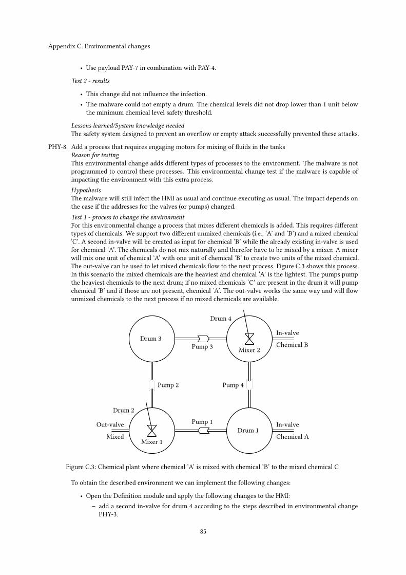
Appendix C. Environmental changes
• Use payload PAY-7 in combination with PAY-4.
Test 2 - results
• This change did not influence the infection.• The malware could not empty a drum. The chemical levels did not drop lower than 1 unit belowthe minimum chemical level safety threshold.
Lessons learned/System knowledge neededThe safety system designed to prevent an overflow or empty attack successfully prevented these attacks.
PHY-8. Add a process that requires engaging motors for mixing of fluids in the tanksReason for testingThis environmental change adds different types of processes to the environment. The malware is notprogrammed to control these processes. This environmental change test if the malware is capable ofimpacting the environment with this extra process.HypothesisThe malware will still infect the HMI as usual and continue executing as usual. The impact depends onthe case if the addresses for the valves (or pumps) changed.Test 1 - process to change the environmentFor this environmental change a process that mixes different chemicals is added. This requires differenttypes of chemicals. We support two different unmixed chemicals (i.e., ‘A’ and ‘B’) and a mixed chemical‘C’. A second in-valve will be created as input for chemical ‘B’ while the already existing in-valve is usedfor chemical ‘A’. The chemicals do not mix naturally and therefor have to be mixed by a mixer. A mixerwill mix one unit of chemical ‘A’ with one unit of chemical ‘B’ to create two units of the mixed chemical.The out-valve can be used to let mixed chemicals flow to the next process. Figure C.3 shows this process.In this scenario the mixed chemicals are the heaviest and chemical ‘A’ is the lightest. The pumps pumpthe heaviest chemicals to the next drum; if no mixed chemicals ‘C’ are present in the drum it will pumpchemical ‘B’ and if those are not present, chemical ‘A’. The out-valve works the same way and will flowunmixed chemicals to the next process if no mixed chemicals are available.
Pump 2
Pump 3
In-valveOut-valveDrum 1
Drum 2
Drum 3
Drum 4
Pump 1
Pump 4
In-valve
MixedMixer 1
Mixer 2
Chemical A
Chemical B
Figure C.3: Chemical plant where chemical ‘A’ is mixed with chemical ‘B’ to the mixed chemical C
To obtain the described environment we can implement the following changes:
• Open the Definition module and apply the following changes to the HMI:– add a second in-valve for drum 4 according to the steps described in environmental change
PHY-3.
85
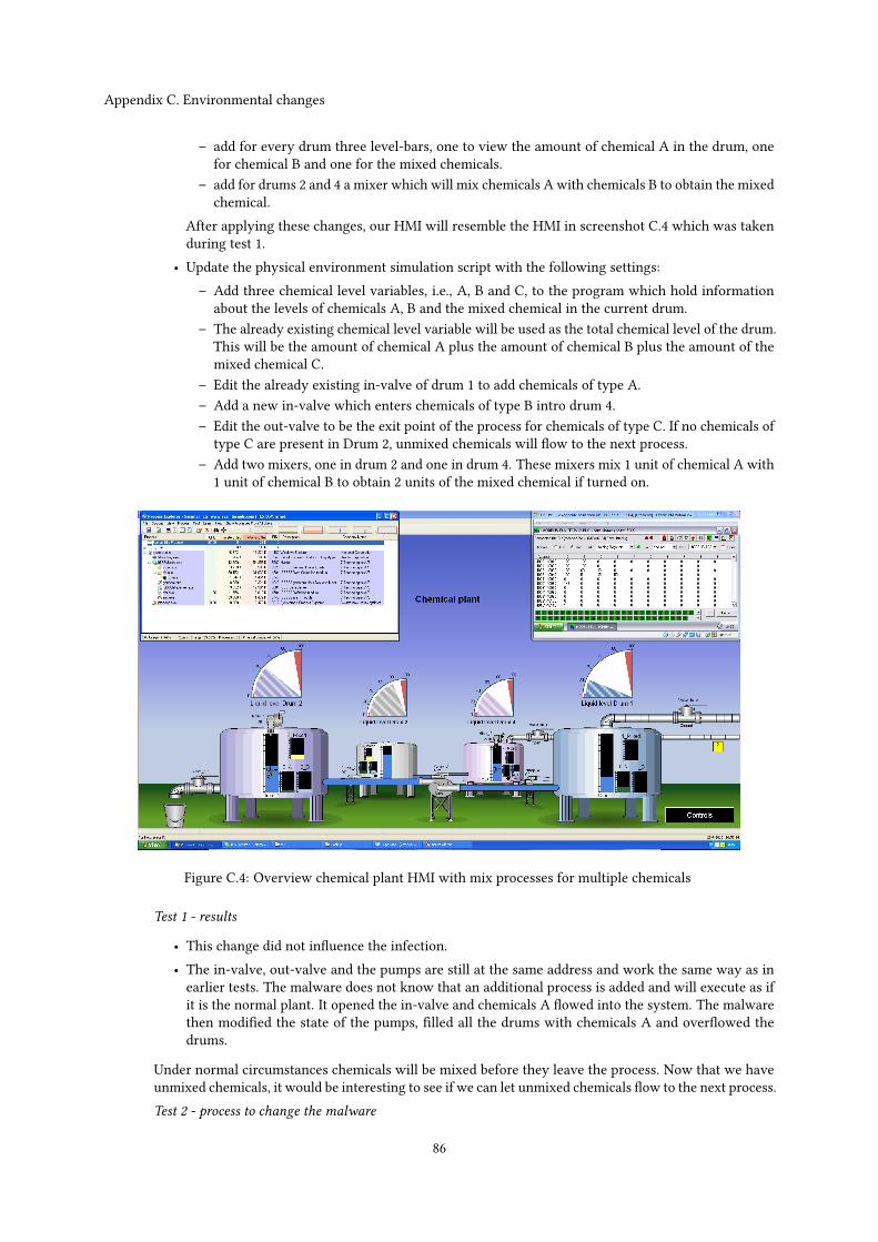
Appendix C. Environmental changes
– add for every drum three level-bars, one to view the amount of chemical A in the drum, onefor chemical B and one for the mixed chemicals.
– add for drums 2 and 4 a mixer which will mix chemicals A with chemicals B to obtain the mixedchemical.
After applying these changes, our HMI will resemble the HMI in screenshot C.4 which was takenduring test 1.
• Update the physical environment simulation script with the following settings:– Add three chemical level variables, i.e., A, B and C, to the program which hold information
about the levels of chemicals A, B and the mixed chemical in the current drum.– The already existing chemical level variable will be used as the total chemical level of the drum.This will be the amount of chemical A plus the amount of chemical B plus the amount of themixed chemical C.
– Edit the already existing in-valve of drum 1 to add chemicals of type A.– Add a new in-valve which enters chemicals of type B intro drum 4.– Edit the out-valve to be the exit point of the process for chemicals of type C. If no chemicals of
type C are present in Drum 2, unmixed chemicals will flow to the next process.– Add two mixers, one in drum 2 and one in drum 4. These mixers mix 1 unit of chemical A with
1 unit of chemical B to obtain 2 units of the mixed chemical if turned on.
Figure C.4: Overview chemical plant HMI with mix processes for multiple chemicals
Test 1 - results
• This change did not influence the infection.• The in-valve, out-valve and the pumps are still at the same address and work the same way as inearlier tests. The malware does not know that an additional process is added and will execute as ifit is the normal plant. It opened the in-valve and chemicals A flowed into the system. The malwarethen modified the state of the pumps, filled all the drums with chemicals A and overflowed thedrums.
Under normal circumstances chemicals will be mixed before they leave the process. Now that we haveunmixed chemicals, it would be interesting to see if we can let unmixed chemicals flow to the next process.Test 2 - process to change the malware
86
Appendix C. Environmental changes
• Use payload PAY-7 in combination with PAY-4.
Test 2 - results
• This change did not influence the infection.• The in-valve, out-valve and the pumps are still at the same address and work the same way as inearlier tests. The malware emptied all drums completely and unmixed chemicals left the processbefore they were mixed.
Test 3 - process to change the malwareThe last results were obtained because the environment was largely the same and no additional modifica-tions on the added process were required to create impact. This test determines the impact if the analyzeris used.
• Use the analysis functionality developed in environmental change PLC-1 ‘Changememory addressesused’.
Test 3 - results
• This change did not influence the infection.• The malware was able to write either the highest or lowest recorded value to each writable PLCregister. The malware has a higher change to overflow the drums since the environment containstwo in-valves and just one out-valve. It is not possible to define the impact on the ICS in advancebecause the state created by the malware is random.
Lessons learned/System knowledge neededIt is possible to just target one process in a control system where multiple processes are controlled. Forexample; we can attack the system by emptying or overflowing the drums. We can also attack the systemby letting unmixed chemicals flow to the next process or by creating a dangerous chemical ratio betweentwo or three chemicals in a drum. We are able to create a potentially harmful state in test 3 for bothprocesses.
87

88
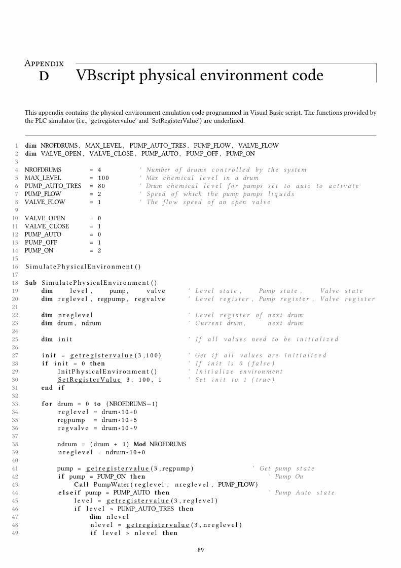
AppendixVBscript physical environment codeD
This appendix contains the physical environment emulation code programmed in Visual Basic script. The functions provided bythe PLC simulator (i.e., ‘getregistervalue’ and ‘SetRegisterValue’) are underlined.
1 dim NROFDRUMS , MAX_LEVEL , PUMP_AUTO_TRES , PUMP_FLOW, VALVE_FLOW2 dim VALVE_OPEN , VALVE_CLOSE , PUMP_AUTO, PUMP_OFF , PUMP_ON34 NROFDRUMS = 4 ' Number o f drums c o n t r o l l e d by t h e sy s t em5 MAX_LEVEL = 100 ' Max ch em i c a l l e v e l i n a drum6 PUMP_AUTO_TRES = 80 ' Drum ch em i c a l l e v e l f o r pumps s e t t o au t o t o a c t i v a t e7 PUMP_FLOW = 2 ' Spe ed o f which t h e pump pumps l i q u i d s8 VALVE_FLOW = 1 ' The f l ow s p e e d o f an open v a l v e910 VALVE_OPEN = 011 VALVE_CLOSE = 112 PUMP_AUTO = 013 PUMP_OFF = 114 PUMP_ON = 21516 S imu l a t ePhy s i c a l Env i r onmen t ( )1718 Sub S imu l a t ePhy s i c a l Env i r onmen t ( )19 dim l e v e l , pump , v a l v e ' L e v e l s t a t e , Pump s t a t e , Va l v e s t a t e20 dim r e g l e v e l , regpump , r e g v a l v e ' L e v e l r e g i s t e r , Pump r e g i s t e r , Va l v e r e g i s t e r2122 dim n r e g l e v e l ' L e v e l r e g i s t e r o f n e x t drum23 dim drum , ndrum ' Cu r r e n t drum , n e x t drum2425 dim i n i t ' I f a l l v a l u e s need t o be i n i t i a l i z e d2627 i n i t = g e t r e g i s t e r v a l u e ( 3 , 1 0 0 ) ' Get i f a l l v a l u e s a r e i n i t i a l i z e d28 i f i n i t = 0 then ' I f i n i t i s 0 ( f a l s e )29 I n i t P hy s i c a l E n v i r o nmen t ( ) ' I n i t i a l i z e env i r onmen t30 S e t R e g i s t e r V a l u e 3 , 1 00 , 1 ' S e t i n i t t o 1 ( t r u e )31 end i f3233 f o r drum = 0 to (NROFDRUMS−1)34 r e g l e v e l = drum ∗10+035 regpump = drum ∗10+536 r e g v a l v e = drum ∗10+93738 ndrum = ( drum + 1 ) Mod NROFDRUMS39 n r e g l e v e l = ndrum ∗10+04041 pump = g e t r e g i s t e r v a l u e ( 3 , regpump ) ' Get pump s t a t e42 i f pump = PUMP_ON then ' Pump On43 Ca l l PumpWater ( r e g l e v e l , n r e g l e v e l , PUMP_FLOW)44 e l s e i f pump = PUMP_AUTO then ' Pump Auto s t a t e45 l e v e l = g e t r e g i s t e r v a l u e ( 3 , r e g l e v e l )46 i f l e v e l > PUMP_AUTO_TRES then47 dim n l e v e l48 n l e v e l = g e t r e g i s t e r v a l u e ( 3 , n r e g l e v e l )49 i f l e v e l > n l e v e l then
89
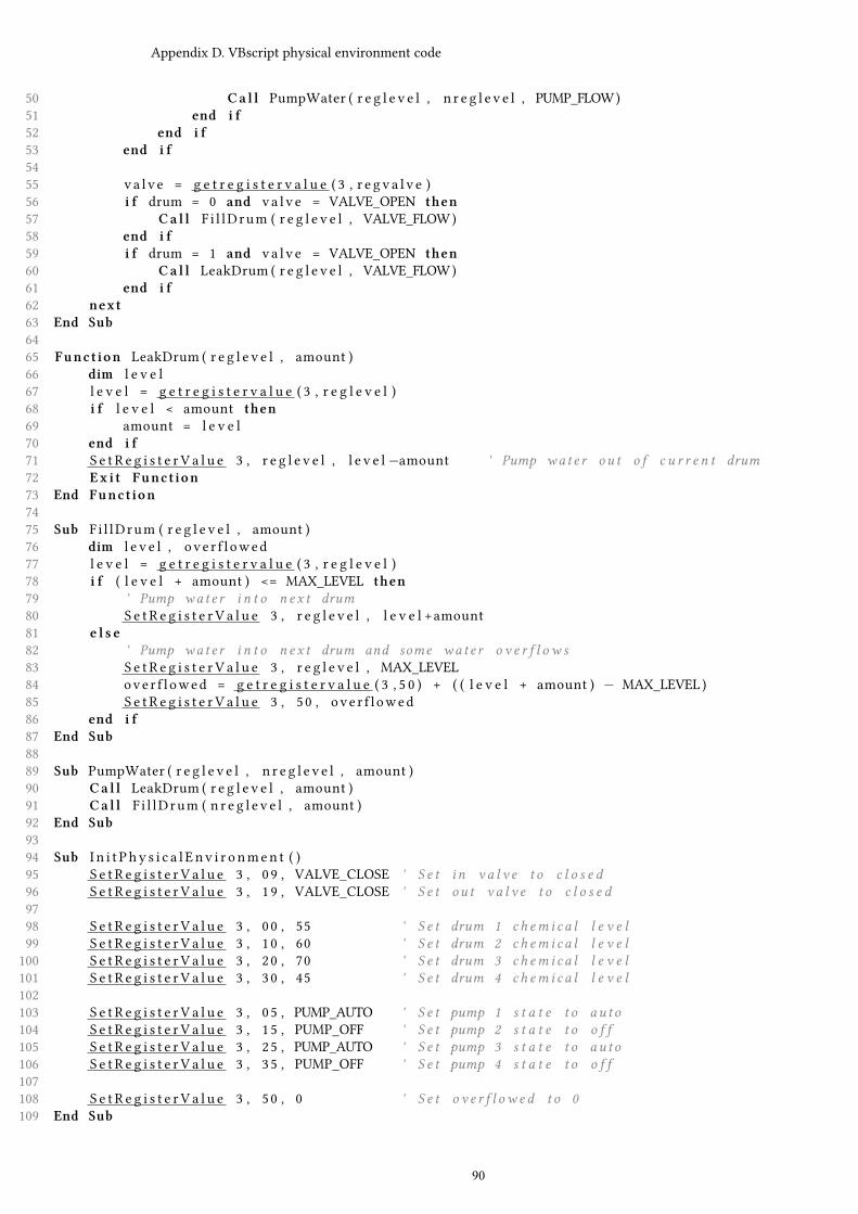
Appendix D. VBscript physical environment code
50 Ca l l PumpWater ( r e g l e v e l , n r e g l e v e l , PUMP_FLOW)51 end i f52 end i f53 end i f5455 va l v e = g e t r e g i s t e r v a l u e ( 3 , r e g v a l v e )56 i f drum = 0 and va l v e = VALVE_OPEN then57 Ca l l F i l lDrum ( r e g l e v e l , VALVE_FLOW)58 end i f59 i f drum = 1 and va l v e = VALVE_OPEN then60 Ca l l LeakDrum ( r e g l e v e l , VALVE_FLOW)61 end i f62 next63 End Sub6465 Funct ion LeakDrum ( r e g l e v e l , amount )66 dim l e v e l67 l e v e l = g e t r e g i s t e r v a l u e ( 3 , r e g l e v e l )68 i f l e v e l < amount then69 amount = l e v e l70 end i f71 S e t R e g i s t e r V a l u e 3 , r e g l e v e l , l e v e l−amount ' Pump wat e r ou t o f c u r r e n t drum72 Ex i t Funct ion73 End Funct ion7475 Sub F i l lDrum ( r e g l e v e l , amount )76 dim l e v e l , ove r f l owed77 l e v e l = g e t r e g i s t e r v a l u e ( 3 , r e g l e v e l )78 i f ( l e v e l + amount ) <= MAX_LEVEL then79 ' Pump wat e r i n t o n e x t drum80 S e t R e g i s t e r V a l u e 3 , r e g l e v e l , l e v e l +amount81 e l s e82 ' Pump wat e r i n t o n e x t drum and some wat e r o v e r f l o w s83 S e t R e g i s t e r V a l u e 3 , r e g l e v e l , MAX_LEVEL84 ove r f l owed = g e t r e g i s t e r v a l u e ( 3 , 5 0 ) + ( ( l e v e l + amount ) − MAX_LEVEL )85 S e t R e g i s t e r V a l u e 3 , 50 , ove r f l owed86 end i f87 End Sub8889 Sub PumpWater ( r e g l e v e l , n r e g l e v e l , amount )90 Ca l l LeakDrum ( r e g l e v e l , amount )91 Ca l l F i l lDrum ( n r e g l e v e l , amount )92 End Sub9394 Sub I n i t P hy s i c a l E nv i r o nmen t ( )95 S e t R e g i s t e r V a l u e 3 , 09 , VALVE_CLOSE ' S e t i n v a l v e t o c l o s e d96 S e t R e g i s t e r V a l u e 3 , 19 , VALVE_CLOSE ' S e t ou t v a l v e t o c l o s e d9798 S e t R e g i s t e r V a l u e 3 , 00 , 55 ' S e t drum 1 ch em i c a l l e v e l99 S e t R e g i s t e r V a l u e 3 , 10 , 60 ' S e t drum 2 ch em i c a l l e v e l100 S e t R e g i s t e r V a l u e 3 , 20 , 70 ' S e t drum 3 ch em i c a l l e v e l101 S e t R e g i s t e r V a l u e 3 , 30 , 45 ' S e t drum 4 ch em i c a l l e v e l102103 S e t R e g i s t e r V a l u e 3 , 05 , PUMP_AUTO ' S e t pump 1 s t a t e t o au t o104 S e t R e g i s t e r V a l u e 3 , 15 , PUMP_OFF ' S e t pump 2 s t a t e t o o f f105 S e t R e g i s t e r V a l u e 3 , 25 , PUMP_AUTO ' S e t pump 3 s t a t e t o au t o106 S e t R e g i s t e r V a l u e 3 , 35 , PUMP_OFF ' S e t pump 4 s t a t e t o o f f107108 S e t R e g i s t e r V a l u e 3 , 50 , 0 ' S e t o v e r f l ow e d t o 0109 End Sub
90
AppendixBibliographyD
[1] Richard Adhikari. As middle eastern malware goes, shamoon’s a strange bird. TechNewsWorld, 08 2012.
[2] Saurabh Amin, Xavier Litrico, S Shankar Sastry, and Alexandre M Bayen. Stealthy deception attacks onwater scada systems. In Proceedings of the 13th ACM international conference on Hybrid systems: computationand control, pages 161–170. ACM, 2010.
[3] Andrea Carcano, Igor Nai Fovino, Marcelo Masera, and Alberto Trombetta. Scada malware, a proof ofconcept. In Critical Information Infrastructure Security, pages 211–222. Springer, 2009.
[4] Alvaro A Cárdenas, Saurabh Amin, Zong-Syun Lin, Yu-Lun Huang, Chi-Yen Huang, and Shankar Sastry.Attacks against process control systems: risk assessment, detection, and response. In Proceedings of the 6thACM Symposium on Information, Computer and Communications Security, pages 355–366. ACM, 2011.
[5] Wang Chunlei, Fang Lan, and Dai Yiqi. A simulation environment for scada security analysis and assessment.InMeasuring Technology andMechatronics Automation (ICMTMA), 2010 International Conference on, volume 1,pages 342–347. IEEE, 2010.
[6] Cisco. Ethernet-to-the-Factory 1.2 Design and Implementation Guide. Cisco, 1.2 edition, July 22 2008. TextPart Number: OL-14268-01.
[7] Budapest University of Technology CrySyS Lab and Economics. skywiper (a.k.a. flame a.k.a. flamer) : Acomplex malware for targeted attacks. page 64, 05 2012.
[8] Alexander Gostev (Kaspersky Lab Expert). The flame: Questions and answers. Securelist, 05 2012.
[9] Nicolas Falliere, Liam OMurchu, and Eric Chien. W32. stuxnet dossier. White paper, Symantec Corp., SecurityResponse, 2011.
[10] I Nai Fovino, Marcelo Masera, Luca Guidi, and Giorgio Carpi. An experimental platform for assessingscada vulnerabilities and countermeasures in power plants. In Human System Interactions (HSI), 2010 3rdConference on, pages 679–686. IEEE, 2010.
[11] Bela Genge, Igor Nai Fovino, Christos Siaterlis, and Marcelo Masera. Analyzing cyber-physical attacks onnetworked industrial control systems. In Critical Infrastructure Protection V, pages 167–183. Springer, 2011.
[12] Béla Genge, Christos Siaterlis, and Marc Hohenadel. Impact of network infrastructure parameters to theeffectiveness of cyber attacks against industrial control systems. 2006.
[13] Béla Genge, Christos Siaterlis, Igor Nai Fovino, and Marcelo Masera. A cyber-physical experimentationenvironment for the security analysis of networked industrial control systems. Computers & ElectricalEngineering, 2012.
[14] Williams T J. The Purdue enterprise reference model, a technical guide for CIM planning and implementation.Instrumentation, System and Automation Society, 1992.
[15] Kaspersky. Resource 207: Kaspersky lab research proves that stuxnet and flame developers are connected.06 2012.
[16] Karen Scarfone Keith Stouffer, Joe Falco. Guide to Industrial Control Systems (ICS) Security. National Instituteof Standards and Technology, special publication 800-82 edition, June 2011.
[17] F.L. Lewis. Introduction to Modern Control Theory: A Brief History of Feedback Control. Prentice-Hall, 1992.Chapter 1 in: F.L. Lewis, Applied Optimal Control and Estimation.
91

Bibliography Bibliography
[18] Marcelo Masera, Igor Nai Fovino, and Rafal Leszczyna. Security assessment of a turbo-gas power plant. InCritical Infrastructure Protection II, pages 31–40. Springer, 2009.
[19] Modbus.org. MODBUS over serial line specification and implementation guide. Modbus.org,http://www.modbus.org/, v1.0 edition, 02 2002.
[20] Thomas Morris, Rayford Vaughn, and Yoginder Dandass. A testbed for scada control system cybersecurityresearch and pedagogy. In proceedings of the Seventh Annual Workshop on Cyber Security and InformationIntelligence Research (CSIIRW’11), 2011.
[21] Igor Nai Fovino, Andrea Carcano, Marcelo Masera, and Alberto Trombetta. An experimental investigationof malware attacks on scada systems. International Journal of Critical Infrastructure Protection, 2(4):139–145,2009.
[22] Andres Perez-Garcia, Christos Siaterlis, and Marcelo Masera. Designing repeatable experiments on anemulab testbed. In Broadband Communications, Networks, and Systems, pages 28–39. Springer, 2012.
[23] Bradley Reaves and Thomas Morris. An open virtual testbed for industrial control system security research.International Journal of Information Security, 11(4):215–229, 2012.
[24] David E. Sanger. Obama order sped up wave of cyberattacks against iran. The New York Times, 6 2012.
[25] F.A. (Floris) Schoenmakers. Perspectives on control system security. Master thesis, Delft University ofTechnology, April 2013. Assessing security risks resulting from contradicting values between Operationaland Information Technology.
[26] McAfee Foundstone Professional Services and McAfee Labs. Global energy cyberattacks: "night dragon".retrieved. page 19, 2 2011.
[27] Jill Slay and Michael Miller. Lessons learned from the maroochy water breach. Springer, 2007.
[28] Symantec. W32.duqu the precursor to the next stuxnet. 11 2011.
[29] André Teixeira, Daniel Pérez, Henrik Sandberg, and Karl Henrik Johansson. Attack models and scenarios fornetworked control systems. In Proceedings of the 1st international conference on High Confidence NetworkedSystems, pages 55–64. ACM, 2012.
[30] Jun Wu and Kazukuni Kobara. Comparison of tools and simulators for control system security studies. InIndustrial Informatics (INDIN), 2012 10th IEEE International Conference on, pages 45–50. IEEE, 2012.
92


![Malware Fails Best Bugs in Malware Felix Leder [Malware ... · 1 Malware Fails Best Bugs in Malware Felix Leder [Malware Detection Team] Felix.Leder@norman.com 5. desember 2011 malware](https://img.pdfslide.net/doc/110x75/5e24a0182957fc7c07460194/malware-fails-best-bugs-in-malware-felix-leder-malware-1-malware-fails-best.jpg)