Embed Size (px)
Citation preview

2

3
KNX function and configuration
Introduction
A presence detector monitors the detection zone for occupancy, and causes one or more actions to be executed when a person enters the detection area. In their simplest form, presence detectors could be used to turn on a light when a person enters a room, and to turn it off again after the person leaves.
This range of presence detectors use the same basic infrared or microwave detection technology, but make use of the KNX system to communicate with other devices. The KNX standard defines how devices should communicate with each other, allowing systems to be constructed using components from many different manufacturers. The standard also guarantees that a presence detector from one manufacturer will effectively control a lighting dimmer or HVAC system from another.
Central to the KNX system is the ETS configuration tool. This application allows an installer to configure all functions of each individual device in the system, and also how triggers and data are passed between different devices. For instance, the tool can be used to set the sensitivity of the presence detector, and can be associated with a particular lighting on-off channel. When someone walks into the room, the light will be turned on, and turned off after a configurable delay. The tool maintains a configuration database for the entire system, and downloads this configuration to each system element.
Functional Description
The presence detector consists of a infrared detector element, reflected light sensor and two SELV switch inputs. The KNX application has been designed to offer the installer a variety of useful functions such as movement detection, manual switch dimming, constant brightness control, user timers, lighting scene recall via infrared handset and simple transmission of input states.
The presence detector consists of two main modes of operation, a preset mode and an advanced mode. In preset mode the internal logic controllers and timers are pre-configured to achieve specific functions such as presence detection and constant brightness control or absence detection and manual switching, along with many others. Using preset modes allows for a quick and easy commissioning process.
When using the device in a preset mode you are presented with a choice of standard functions/ modes. Once the relevant mode has been selected you can assign values to parameters in the Settings tab. Only parameters relevant to that mode will be made visible. Once the various parameters have been set the user is required to assign group addresses via the group objects tab. Only group objects relevant to the selected mode will be visible.
For more bespoke functionality the device can be used in advanced mode. This mode should only be required when you have a specific function that is not covered by any of the preset modes.
If the device is used in advanced mode the internal logic controllers and user timers are made visible to the user. The expressions within the Logic controllers and user timers will need to be configured to achieve the required functionality. Depending on the configuration of the logic controllers the relevant group objects will be made visible in the group objects tab. The user is required to assign group addresses to the relevant group objects.
For larger rooms, several presence detectors can be used to increase the coverage area. In this configuration, one presence detector acts as the master, and all other detectors act as slaves. When movement is detected by any of the slave detectors, a telegram is sent to the master over the KNX bus. The master detector uses this information as part of a logic expression to send dimming, scene recall or brightness commands to the controlled device. The movement timeout period is defined on the master device; slave devices simply need to send a telegram whenever movement is sensed.
Configuration
Import the device definitions into ETS Download the ETS product file containing all the data for the CP Electronics KNX detector range from the appropriate page on the CP Electronics website, and import it into your ETS application as a product catalogue. Once imported, the device can be added to a project, assigned an individual address, and have its behaviour programmed.
Putting the device into programming mode The first time you program the detector you need to put it into programming mode. After you assign the device an address in ETS you can also put it into programming mode directly from ETS.
Exiting programming mode The device automatically leaves programming mode after ETS programming is complete. If you have the UHS5 handset: you can exit programming mode before the detector has been programmed:

4
Each Preset Mode has been defined using options and logic controllers available in Advanced Mode. For ease of implementation, logic controllers perform the same functions in each of the various preset modes. More information on how these modes are implemented in Advanced Mode is the subject of a separate manual.
Logic controller 1 (motion): responsible for switching on the lights, either through motion detection, slave motion
detection or manual switch input. The controller will send either a binary 'on' command, recall a scene, or recall a specific brightness value
Logic controller 2 (motion): responsible for switching off the lights, or setting a standby level at the end of the
motion event. The controller sends either a binary 'off' command, or a brightness value depending on configuration
Logic controller 3 (brightness): responsible for maintaining a particular brightness level by adjusting the value
sent to the dimmer. In some modes, the controller will be used to maintain a constant brightness level through use of the built-in lux sensor. Other modes use this controller to send user-specified brightness values to the dimmer, i.e. in response to dim up and dim down commands
User timer 1: responsible for performing an action at the end of a standby illumination period, if configured.
Typically this will switch off the lights by way of an 'off' telegram, although it can also recall a scene or set a brightness value
KNX function and configuration (continued)
Preset modes
Presence Modes (fully automatic)
Presence detection & manual switching & dimming.
Presence detection and constant brightness control.
Presence detection, constant brightness control, and Man-ual Switching and dimming.
Presence detection, constant brightness control, Manual Switching and dimming, and lux switching.
Presence detection and lux switching.
Absence Modes (semi-automatic)
Absence detection and Manual switching
Absence detection and Constant brightness control
Absence detection, constant brightness control and manual switching and dimming.
Absence detection, constant brightness control and lux switching.
Absence detection and lux switching.
Photocell Modes
Constant brightness control.
Constant brightness control & manual switching & dimming.
Lux switching.
Lux switching and manual switching and dimming.
Other Modes
Manual Switching and dimming
Slave mode
Setting Options Description
Set Movement Timeout Remotely Yes/ No Movement timeout may be set statically using ETS or alternatively set by
other devices on the KNX bus.
Movement Timeout 0-32767 secs, 0-546 mins, 0-9
hours
How long to wait after the last movement is detected before signalling a
movement cleared state
Detector Sensitivity 0-9 Increase or decrease the detector’s sensitivity to movement. 0 is least
sensitive, 9 is most sensitive. The sensitivity can be overridden by infrared
remote, but will be overwritten when parameters are updated via ETS
Walk Test LED Disable, Enable Enable or disable the sensor walk test LED, triggered when movement is
detected. This is useful for commissioning or if the detector is to be used in bedrooms. Note that the walk test function can also be turned on and off via
infrared remote control.
Initial Brightness level On telegram, Dimmer Value 0-
100%, Scene Number 1-64 Specify the type of control signal sent once movement has been detected.
Mask Sensor Re-triggers within
time period Yes/ No If set to 'No' the slave sensor will send 'ON' telegrams on every movement
event. If set to 'Yes' and for example a mask time period of 1 minute is set, when movement is detected an 'On' telegram will be sent every 59 seconds, triggers within this time period are masked to reduce bus traffic. This
parameter may be useful in installations using large numbers of slave
sensors on the same KNX segment.
Mask Period 0-32767 secs, 0-546 mins, 0-9
hours Define the mask period.
Detector settings
Preset modes settings

5
Setting Options Description
Switch On Threshold 0-100000 Lux Defines the lux level that the measured lux level must be below before the
lighting is switched on. If the measured lux level is above this threshold the
lights will remain off.
Switch OFF Threshold 0-100000 Lux Defines the lux level that the measured lux level must be Above before the
lighting is switched off. If the measured lux level is below this threshold the
lights will remain on.
Lux Switch Delay 0-32767 secs, 0-546 mins, 0-9
hours
Specifies the amount of time that the measured lux level must be above the
switch off threshold before the lighting is switched off or to a standby level. This is useful to mask the effects of moving clouds that may cause the lighting to switch off undesirably. Note this delay only applies to the Switch
OFF threshold.
Lux Multiplier 0-100000 Value to multiply raw light level readings by to obtain true lux value. In
practice, this will need to be set with the aid of a light meter in the environment that the detector is used in, as reflected light and even choice of
furnishings can dramatically affect the readings obtained.
Light Level Transmission mode Send Light level cyclically 0-
65535s, Send light level on
change 0-100%
Choose either to send light level telegrams on the bus cyclically at the
specified rate or only when there is a change greater than the percentage
specified.
Send Light level telegrams every 0-65535s Defines how often to send light level telegrams if the light level transmission
mode is set to 'send light level cyclically'
Do Not send Light level if within 0-1000 Lux Defines how often to send light level telegrams if the light level transmission
mode is set to 'Send light level on change'
Setting Options Description
Set Target lux value remotely Yes/ No The target lux level may be set statically via ETS or remotely via other devices on the bus
Target Lux Value 0-1000 Lux Target value in lux for the brightness controller to aim for.
Brightness delay 0-32767 secs, 0-546
mins, 0-9 hours
Specify the amount of time that the measured lux level must be out of the target lux range
( target lux value +/- dimming deadband) before the brightness controller sends dimming
telegrams.
Dimming Increment 100%
50% 25% 12.5%
6.25% 3.125%
1.5625%
The amount by which each subsequent dimming telegram raises or lowers the light level.
Typically a small value will be used here, but will depend on the environment. Large
values may cause the dimmer to oscillate between light and dark.
Dimming Deadband 0-1000 Lux Deadband value in lux within which the controller will not attempt to vary the light output. If
set to 50 the controller will not attempt to vary the light output unless the measured lux
level is +/- 50 lux of the target lux value.
Lux Multiplier 0-100000 Value to multiply raw light level readings by to obtain true lux value. In practice, this will
need to be set with the aid of a light meter in the environment that the detector is used in, as reflected light and even choice of furnishings will dramatically affect the readings
obtained.
Light Level Transmission
mode
Send Light level cyclically
0-65535s, Send light level
on change 0-1000 Lux
Choose either to send light level telegrams on the bus cyclically at the specified rate or
only when there is a change greater than the lux value specified.
Send Light level telegrams
every 0-65535s Defines how often to send light level telegrams if the light level transmission mode is set
to 'send light level cyclically'
Do Not send Light level if
within 0-1000 Lux Defines how often to send light level telegrams if the light level transmission mode is set
to 'Send light level on change'
Telegram Interval 0-65535ms Specify the rate to send constant brightness control telegrams when the measured lux
level is out of the target lux range, (target lux value +/- dimming deadband)
PRESET MODES SETTINGS: Lux switching
PRESET MODES SETTINGS: Constant brightness control
KNX function and configuration (continued)

6
KNX function and configuration (continued)
Setting Options Description
Standby Level Yes/ No Choose whether to implement a standby light level. The standby light level is
set when movement has cleared or (if using modes with lux switching) when the measured lux level is above the 'switch off threshold'. This allows the user to set a low level of light for when the area is unoccupied, in safety
critical applications
Value 0-100% Define the percentage level the lights will go to when movement has cleared
or a lux switch off event has occurred
Standby Timeout Yes/ No Select whether to hold the lights at the standby level indefinitely until the
next movement or lux switch event occurs, or to stay at the standby level for a set period of time after which the lights can be switched off entirely or go to
another specified level.
Standby Timer Duration 0-32767 secs, 0-546 mins, 0-9 Defines the amount of time that the lights stay at the standby level.
Action on standby timeout OFF telegram, Brightness value,
Scene number Define the type of control signal sent when the standby time has elapsed.
Brightness 0-100% If the 'action on standby timeout' is set to 'brightness value', this parameter
defines the brightness percentage sent when the standby timer elapses.
Scene number 0-64 If the 'action on standby timeout' is set to 'Scene number', this parameter
defines the scene number sent when the standby timer elapses.
PRESET MODES SETTINGS: Standby
Setting Options Description
Switch telegram repeat interval 0-65535ms Define the interval between repeat dimming telegrams (dim up / dim down
telegrams). This parameter allows you to control the speed of manual dimming, if found to be too slow decrease this value if too fast increase this
Dim up/ dim down step
percentage
100%
50% 25% 12.5%
6.25% 3.125%
1.5625%
The percentage to add or subtract from the current dimmer value when the
relevant button is pressed. Smaller percentages offer finer-grained control,
but require the user to press the button more times to change the light level.
Manual Override time 0-32767 secs, 0-546 mins, 0-9
hours
Define the amount of time that a switch input event will override the logic and
brightness controllers. When using the device in a photocell mode this parameter allows you to define a period of time in which the brightness controllers and logic controllers will be overridden by a switch input event
such as switching the lights off or dimming the lights down for a
presentation.
PRESET MODES SETTINGS: Switch

7
Lights will be switched on automatically when movement is detected, and switched off automatically when movement has ceased and the movement timeout period has elapsed. The lights can be switched on or off and dimmed up and down via a two position centre-biased retractive switch wired to sw1 and sw2. Sw1 input will send an On telegram when pressed momentarily or dim up when held. Sw2 input will send an off telegram when pressed momentarily or dim down when held.
Group object Description
Logic Controller 1 (motion) - Switch state output Binary switch-on telegram sent to turn on connected device at start of controlled event, when
'Initial brightness level' is set to 'On telegram'.
This should be linked to the dimmer's on/off group object.
Logic Controller 1 (motion) - Slave trigger input Input from one or more slave movement sensors, allowing several sensors to cover a larger
area. The master unit is responsible for all timing. This should be linked to the slave sensor's switch state output when it has been set to slave
mode.
Logic Controller 1 (motion) - Movement timeout input Allows movement timeout period to be adjusted remotely if required, for instance allowing a
shorter timeout at night to be programmed. This group object is available when 'Set movement timeout remotely' is set to 'Yes'.
All movement timeout inputs on the master sensor should be linked to a device providing this
timeout value. The value is in seconds.
Logic Controller 1 (motion) - Absolute dimmer
percentage output
Percentage value sent to turn on connected device at start of controlled event, when 'Initial
brightness level' is set to 'Brightness value'.
This should be linked to the dimmer's absolute dimming (percentage) group object.
Logic Controller 1 (motion) - Scene recall output Scene number sent to turn on connected device at start of controlled event, when 'Initial
brightness level' is set to 'Scene number'.
This should be linked to the dimmer's scene recall group object.
Logic Controller 2 (motion) - Switch state output Binary switch-off telegram sent to turn off the connected device at the end of the controlled
event, when 'Standby level' is set to 'No'.
This should be linked to the dimmer's on/off group object.
Logic Controller 2 (motion) - Slave trigger input Input from one or more slave movement sensors, allowing several sensors to cover a larger
area. The master unit is responsible for all timing. This should be linked to the slave sensor's switch state output when it has been set to slave
mode.
Logic Controller 2 (motion) - Movement timeout input Allows movement timeout period to be adjusted remotely if required, for instance allowing a
shorter timeout at night to be programmed. This group object is available when 'Set movement timeout remotely' is set to 'Yes'.
All movement timeout inputs on the master sensor should be linked to a device providing this
timeout value. The value is in seconds.
Logic Controller 2 (motion) - Absolute dimmer
percentage output
Sets a standby illumination percentage at the end of the controlled event, rather than turning
the connected lights off. This requires 'Standby level' to be set to 'Yes'.
This should be linked to the dimmer's absolute dimming (percentage) group object.
Logic Controller 3 (motion) - Percentage output For modes incorporating either constant brightness control or manual dimming, this provides an
absolute percentage value for the controlled dimmer. Depending on the mode, it will be adjusted up and down to maintain a constant brightness, or a brightness level specified by the user via remote switch.
This should be linked to the dimmer's absolute dimming (percentage) group object.
Logic Controller 3 (motion) - Dimmer feedback input Feedback from the dimmer is used to determine a starting value for certain dimming and
constant brightness modes.
This should be linked to the dimmer's absolute (percentage) feedback group object if available.
PRESET MODE: Presence detection and Manual Switching and Dimming
Preset modes
KNX function and configuration (continued)

8
Group object Description
Logic Controller 3 (motion) - Dimmer feedback input Feedback from the dimmer is used to determine a starting value for certain dimming and
constant brightness modes.
This should be linked to the dimmer's absolute (percentage) feedback group object if available.
Logic Controller 3 (motion) - Dimmer feedback input Feedback from the dimmer is used to determine a starting value for certain dimming and
constant brightness modes.
This should be linked to the dimmer's absolute (percentage) feedback group object if available.
Logic Controller 3 (motion) - Dimmer override input 4-bit dim up/dim down telegram input, allowing remote KNX switches to vary the brightness level
in some modes. This is equivalent to using built-in GPI inputs or IR remote control to vary the brightness level.
This should be linked to the remote switch 4-bit relative dimming output group object.
User Timer 1 - Switch state output Binary switch-off telegram sent to turn off the connected device at the end of the standby
timeout, when 'Standby level' is set to 'Yes', and 'Action on standby timeout' is set to 'Off telegram'.
This should be linked to the dimmer's on/off group object.
User Timer 1 - Slave trigger input Input from one or more slave movement sensors, allowing several sensors to cover a larger
area. The master unit is responsible for all timing. This should be linked to the slave sensor's switch state output when it has been set to slave
mode.
User Timer 1 - movement timeout input Allows movement timeout period to be adjusted remotely if required, for instance allowing a
shorter timeout at night to be programmed. This group object is available when 'Set movement timeout remotely' is set to 'Yes'.
All movement timeout inputs on the master sensor should be linked to a device providing this
timeout value. The value is in seconds.
User Timer 1 - Absolute dimmer percentage out Absolute dimmer percentage telegram sent to the connected device at the end of the standby
timeout, when 'Standby level' is set to 'Yes', and 'Action on standby timeout' is set to 'Brightness value'.
This should be linked to the dimmer's absolute dimming (percentage) group object.
User Timer 1 - Scene recall output Scene recall telegram sent to the connected device at the end of the standby timeout, when
'Standby level' is set to 'Yes', and 'Action on standby timeout' is set to 'Scene number'.
This should be linked to the dimmer's scene recall group object.
IR remote control - Scene recall output Independent scene recall output for use with a compatible IR remote control, allowing a scene to
be recalled on a compatible dimmer.
This should be linked to the dimmer's scene recall group object.
IR remote control - Switch output Switch on/off output for use with a compatible IR remote control, allowing a remote device to be
switched on or off. Note that in some modes, IR switch status is automatically processed, and there is no need to link to this group object.
This should be linked to the controlled device's on/off control group object.
IR remote control - Dimming control output Dim up/dim down output for use with a compatible IR remote control, allowing adjustment of a
remote dimmer's brightness value. Note that in some modes, IR dim up/dim down commands are automatically processed, and there is no need to link to this group object.
This should be linked to the controlled dimmer's 4-bit relative dimming group object.
KNX function and configuration (continued)
PRESET MODE: Presence detection and Manual Switching and Dimming (continued)

9
Lights will be switched on automatically when movement is detected, and switched off automatically when movement has ceased and the movement timeout period has elapsed. When the sensor has detected movement the Constant brightness controller within the detector will aim to maintain a target lux value set by the user.
Group object Description
Logic Controller 1 (motion) - Switch state output Binary switch-on telegram sent to turn on connected device at start of controlled event, when
'Initial brightness level' is set to 'On telegram'.
This should be linked to the dimmer's on/off group object.
Logic Controller 1 (motion) - Slave trigger input Input from one or more slave movement sensors, allowing several sensors to cover a larger
area. The master unit is responsible for all timing. This should be linked to the slave sensor's switch state output when it has been set to slave
Logic Controller 1 (motion) - Movement timeout input Allows movement timeout period to be adjusted remotely if required, for instance allowing a
shorter timeout at night to be programmed. This group object is available when 'Set movement timeout remotely' is set to 'Yes'.
All movement timeout inputs on the master sensor should be linked to a device providing this
timeout value. The value is in seconds.
Logic Controller 1 (motion) - Absolute dimmer
percentage output
Percentage value sent to turn on connected device at start of controlled event, when 'Initial
brightness level' is set to 'Brightness value'.
This should be linked to the dimmer's absolute dimming (percentage) group object.
Logic Controller 1 (motion) - Scene recall output Scene number sent to turn on connected device at start of controlled event, when 'Initial
brightness level' is set to 'Scene number'.
This should be linked to the dimmer's scene recall group object.
Logic Controller 2 (motion) - Switch state output Binary switch-off telegram sent to turn off the connected device at the end of the controlled
event, when 'Standby level' is set to 'No'.
This should be linked to the dimmer's on/off group object.
Logic Controller 2 (motion) - Slave trigger input Input from one or more slave movement sensors, allowing several sensors to cover a larger
area. The master unit is responsible for all timing. This should be linked to the slave sensor's switch state output when it has been set to slave
Logic Controller 2 (motion) - Movement timeout input Allows movement timeout period to be adjusted remotely if required, for instance allowing a
shorter timeout at night to be programmed. This group object is available when 'Set movement timeout remotely' is set to 'Yes'.
All movement timeout inputs on the master sensor should be linked to a device providing this
timeout value. The value is in seconds.
Logic Controller 2 (motion) - Absolute dimmer
percentage output
Sets a standby illumination percentage at the end of the controlled event, rather than turning
the connected lights off. This requires 'Standby level' to be set to 'Yes'.
This should be linked to the dimmer's absolute dimming (percentage) group object.
Logic Controller 3 (motion) - Percentage output For modes incorporating either constant brightness control or manual dimming, this provides
an absolute percentage value for the controlled dimmer. Depending on the mode, it will be adjusted up and down to maintain a constant brightness, or a brightness level specified by the user via remote switch.
This should be linked to the dimmer's absolute dimming (percentage) group object.
Logic Controller 3 (motion) - Dimmer feedback input Feedback from the dimmer is used to determine a starting value for certain dimming and
constant brightness modes.
This should be linked to the dimmer's absolute (percentage) feedback group object if available.
PRESET MODE: Presence Detection and Constant Brightness Control
KNX function and configuration (continued)

10
Group object Description
Logic Controller 3 (motion) - Dimmer override
input
4-bit dim up/dim down telegram input, allowing remote KNX switches to vary the brightness level
in some modes. This is equivalent to using built-in GPI inputs or IR remote control to vary the brightness level.
This should be linked to the remote switch 4-bit relative dimming output group object.
Logic Controller 3 (motion) - Target lux input Allows the lux target to be adjusted remotely if required, for instance allowing a lower lux target on
weekends. This group object is available when 'Set target lux value remotely' is set to 'Yes'.
User Timer 1 - Switch state output Binary switch-off telegram sent to turn off the connected device at the end of the standby timeout,
when 'Standby level' is set to 'Yes', and 'Action on standby timeout' is set to 'Off telegram'.
This should be linked to the dimmer's on/off group object.
User Timer 1 - Slave trigger input Input from one or more slave movement sensors, allowing several sensors to cover a larger area.
The master unit is responsible for all timing. This should be linked to the slave sensor's switch state output when it has been set to slave
User Timer 1 - movement timeout input Allows movement timeout period to be adjusted remotely if required, for instance allowing a
shorter timeout at night to be programmed. This group object is available when 'Set movement timeout remotely' is set to 'Yes'.
All movement timeout inputs on the master sensor should be linked to a device providing this
timeout value. The value is in seconds.
User Timer 1 - Absolute dimmer percentage out Absolute dimmer percentage telegram sent to the connected device at the end of the standby
timeout, when 'Standby level' is set to 'Yes', and 'Action on standby timeout' is set to 'Brightness value'.
This should be linked to the dimmer's absolute dimming (percentage) group object.
User Timer 1 - Scene recall output Scene recall telegram sent to the connected device at the end of the standby timeout, when
'Standby level' is set to 'Yes', and 'Action on standby timeout' is set to 'Scene number'.
This should be linked to the dimmer's scene recall group object.
General - Light level output Transmits the measured lux level from the sensor onto the KNX bus at the specified rate.
IR remote control - Scene recall output Independent scene recall output for use with a compatible IR remote control, allowing a scene to
be recalled on a compatible dimmer.
This should be linked to the dimmer's scene recall group object.
IR remote control - Switch output Switch on/off output for use with a compatible IR remote control, allowing a remote device to be
switched on or off. Note that in some modes, IR switch status is automatically processed, and there is no need to link to this group object.
This should be linked to the controlled device's on/off control group object.
IR remote control - Dimming control output Dim up/dim down output for use with a compatible IR remote control, allowing adjustment of a
remote dimmer's brightness value. Note that in some modes, IR dim up/dim down commands are automatically processed, and there is no need to link to this group object.
This should be linked to the controlled dimmer's 4-bit relative dimming group object.
KNX function and configuration (continued)
PRESET MODE: Presence Detection and Constant Brightness Control
(continued)
11
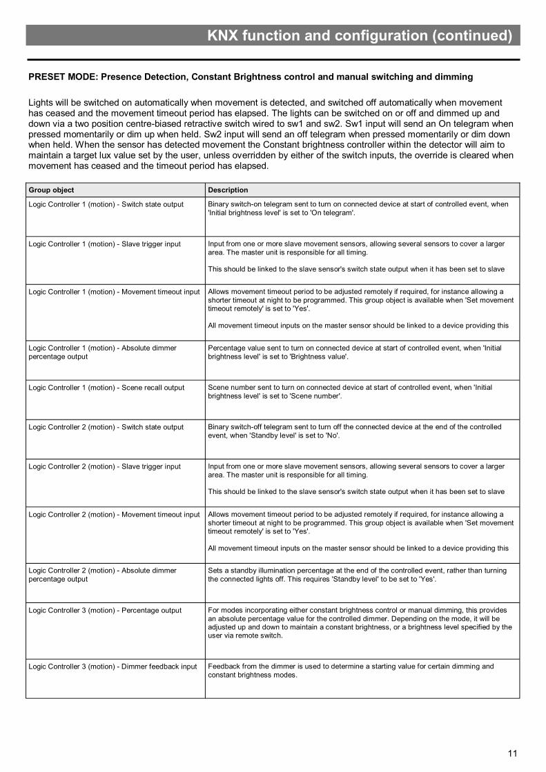
Lights will be switched on automatically when movement is detected, and switched off automatically when movement has ceased and the movement timeout period has elapsed. The lights can be switched on or off and dimmed up and down via a two position centre-biased retractive switch wired to sw1 and sw2. Sw1 input will send an On telegram when pressed momentarily or dim up when held. Sw2 input will send an off telegram when pressed momentarily or dim down when held. When the sensor has detected movement the Constant brightness controller within the detector will aim to maintain a target lux value set by the user, unless overridden by either of the switch inputs, the override is cleared when movement has ceased and the timeout period has elapsed.
Group object Description
Logic Controller 1 (motion) - Switch state output Binary switch-on telegram sent to turn on connected device at start of controlled event, when
'Initial brightness level' is set to 'On telegram'.
Logic Controller 1 (motion) - Slave trigger input Input from one or more slave movement sensors, allowing several sensors to cover a larger
area. The master unit is responsible for all timing. This should be linked to the slave sensor's switch state output when it has been set to slave
Logic Controller 1 (motion) - Movement timeout input Allows movement timeout period to be adjusted remotely if required, for instance allowing a
shorter timeout at night to be programmed. This group object is available when 'Set movement timeout remotely' is set to 'Yes'.
All movement timeout inputs on the master sensor should be linked to a device providing this
Logic Controller 1 (motion) - Absolute dimmer
percentage output
Percentage value sent to turn on connected device at start of controlled event, when 'Initial
brightness level' is set to 'Brightness value'.
Logic Controller 1 (motion) - Scene recall output Scene number sent to turn on connected device at start of controlled event, when 'Initial
brightness level' is set to 'Scene number'.
Logic Controller 2 (motion) - Switch state output Binary switch-off telegram sent to turn off the connected device at the end of the controlled
event, when 'Standby level' is set to 'No'.
Logic Controller 2 (motion) - Slave trigger input Input from one or more slave movement sensors, allowing several sensors to cover a larger
area. The master unit is responsible for all timing. This should be linked to the slave sensor's switch state output when it has been set to slave
Logic Controller 2 (motion) - Movement timeout input Allows movement timeout period to be adjusted remotely if required, for instance allowing a
shorter timeout at night to be programmed. This group object is available when 'Set movement timeout remotely' is set to 'Yes'.
All movement timeout inputs on the master sensor should be linked to a device providing this
Logic Controller 2 (motion) - Absolute dimmer
percentage output
Sets a standby illumination percentage at the end of the controlled event, rather than turning
the connected lights off. This requires 'Standby level' to be set to 'Yes'.
Logic Controller 3 (motion) - Percentage output For modes incorporating either constant brightness control or manual dimming, this provides
an absolute percentage value for the controlled dimmer. Depending on the mode, it will be adjusted up and down to maintain a constant brightness, or a brightness level specified by the user via remote switch.
Logic Controller 3 (motion) - Dimmer feedback input Feedback from the dimmer is used to determine a starting value for certain dimming and
constant brightness modes.
KNX function and configuration (continued)
PRESET MODE: Presence Detection, Constant Brightness control and manual switching and dimming

12
PRESET MODE: Presence Detection, Constant Brightness control and manual switching and dimming (continued)
Group object Description
Logic Controller 3 (motion) - Dimmer override
input
4-bit dim up/dim down telegram input, allowing remote KNX switches to vary the brightness level in
some modes. This is equivalent to using built-in GPI inputs or IR remote control to vary the brightness level.
Logic Controller 3 (motion) - Target lux input Allows the lux target to be adjusted remotely if required, for instance allowing a lower lux target on
weekends. This group object is available when 'Set target lux value remotely' is set to 'Yes'.
User Timer 1 - Switch state output Binary switch-off telegram sent to turn off the connected device at the end of the standby timeout,
when 'Standby level' is set to 'Yes', and 'Action on standby timeout' is set to 'Off telegram'.
This should be linked to the dimmer's on/off group object.
User Timer 1 - Slave trigger input Input from one or more slave movement sensors, allowing several sensors to cover a larger area.
The master unit is responsible for all timing.
This should be linked to the slave sensor's switch state output when it has been set to slave mode.
User Timer 1 - movement timeout input Allows movement timeout period to be adjusted remotely if required, for instance allowing a shorter
timeout at night to be programmed. This group object is available when 'Set movement timeout remotely' is set to 'Yes'.
All movement timeout inputs on the master sensor should be linked to a device providing this
timeout value. The value is in seconds.
User Timer 1 - Absolute dimmer percentage out Absolute dimmer percentage telegram sent to the connected device at the end of the standby
timeout, when 'Standby level' is set to 'Yes', and 'Action on standby timeout' is set to 'Brightness value'.
This should be linked to the dimmer's absolute dimming (percentage) group object.
User Timer 1 - Scene recall output Scene recall telegram sent to the connected device at the end of the standby timeout, when
'Standby level' is set to 'Yes', and 'Action on standby timeout' is set to 'Scene number'.
This should be linked to the dimmer's scene recall group object.
General - Light level output Transmits the measured lux level from the sensor onto the KNX bus at the specified rate.
IR remote control - Scene recall output Independent scene recall output for use with a compatible IR remote control, allowing a scene to
be recalled on a compatible dimmer.
This should be linked to the dimmer's scene recall group object.
IR remote control - Switch output Switch on/off output for use with a compatible IR remote control, allowing a remote device to be
switched on or off. Note that in some modes, IR switch status is automatically processed, and there is no need to link to this group object.
This should be linked to the controlled device's on/off control group object.
IR remote control - Dimming control output Dim up/dim down output for use with a compatible IR remote control, allowing adjustment of a
remote dimmer's brightness value. Note that in some modes, IR dim up/dim down commands are automatically processed, and there is no need to link to this group object.
This should be linked to the controlled dimmer's 4-bit relative dimming group object.
KNX function and configuration (continued)

13
Lights will be switched on automatically when movement is detected provided the measured lux level is below the 'switch on threshold' set. The lights will be switched off automatically when movement has ceased and the movement timeout period has elapsed. The lights can be switched on or off and dimmed up and down via a two position centre-biased retractive switch wired to sw1 and sw2. Sw1 input will send an On telegram when pressed momentarily or dim up when held. Sw2 input will send an off telegram when pressed momentarily or dim down when held. When the sensor has detected movement the Constant brightness controller within the detector will aim to maintain a target lux value set by the user, unless overridden by either of the switch inputs, the override is cleared when movement has ceased and the timeout period has elapsed.
Group object Description
Logic Controller 1 (motion) - Switch state output Binary switch-on telegram sent to turn on connected device at start of controlled event, when
'Initial brightness level' is set to 'On telegram'.
This should be linked to the dimmer's on/off group object.
Logic Controller 1 (motion) - Slave trigger input Input from one or more slave movement sensors, allowing several sensors to cover a larger
area. The master unit is responsible for all timing. This should be linked to the slave sensor's switch state output when it has been set to slave
Logic Controller 1 (motion) - Movement timeout input Allows movement timeout period to be adjusted remotely if required, for instance allowing a
shorter timeout at night to be programmed. This group object is available when 'Set movement timeout remotely' is set to 'Yes'.
All movement timeout inputs on the master sensor should be linked to a device providing this
timeout value. The value is in seconds.
Logic Controller 1 (motion) - Absolute dimmer
percentage output
Percentage value sent to turn on connected device at start of controlled event, when 'Initial
brightness level' is set to 'Brightness value'.
This should be linked to the dimmer's absolute dimming (percentage) group object.
Logic Controller 1 (motion) - Scene recall output Scene number sent to turn on connected device at start of controlled event, when 'Initial
brightness level' is set to 'Scene number'.
This should be linked to the dimmer's scene recall group object.
Logic Controller 2 (motion) - Switch state output Binary switch-off telegram sent to turn off the connected device at the end of the controlled
event, when 'Standby level' is set to 'No'.
This should be linked to the dimmer's on/off group object.
Logic Controller 2 (motion) - Slave trigger input Input from one or more slave movement sensors, allowing several sensors to cover a larger
area. The master unit is responsible for all timing. This should be linked to the slave sensor's switch state output when it has been set to slave
Logic Controller 2 (motion) - Movement timeout input Allows movement timeout period to be adjusted remotely if required, for instance allowing a
shorter timeout at night to be programmed. This group object is available when 'Set movement timeout remotely' is set to 'Yes'.
All movement timeout inputs on the master sensor should be linked to a device providing this
timeout value. The value is in seconds.
Logic Controller 2 (motion) - Absolute dimmer
percentage output
Sets a standby illumination percentage at the end of the controlled event, rather than turning
the connected lights off. This requires 'Standby level' to be set to 'Yes'.
This should be linked to the dimmer's absolute dimming (percentage) group object.
Logic Controller 3 (motion) - Percentage output For modes incorporating either constant brightness control or manual dimming, this provides
an absolute percentage value for the controlled dimmer. Depending on the mode, it will be adjusted up and down to maintain a constant brightness, or a brightness level specified by the user via remote switch.
This should be linked to the dimmer's absolute dimming (percentage) group object.
Logic Controller 3 (motion) - Dimmer feedback input Feedback from the dimmer is used to determine a starting value for certain dimming and
constant brightness modes. This should be linked to the dimmer's absolute (percentage) feedback group object if
PRESET MODE: Presence Detection, Constant Brightness control, manual switching and dimming and lux
switching
KNX function and configuration (continued)

14
Group object Description
Logic Controller 3 (motion) - Dimmer override input 4-bit dim up/dim down telegram input, allowing remote KNX switches to vary the brightness level
in some modes. This is equivalent to using built-in GPI inputs or IR remote control to vary the brightness level.
Logic Controller 3 (motion) - Target lux input Allows the lux target to be adjusted remotely if required, for instance allowing a lower lux target
on weekends. This group object is available when 'Set target lux value remotely' is set to 'Yes'.
User Timer 1 - Switch state output Binary switch-off telegram sent to turn off the connected device at the end of the standby
timeout, when 'Standby level' is set to 'Yes', and 'Action on standby timeout' is set to 'Off telegram'.
User Timer 1 - Slave trigger input Input from one or more slave movement sensors, allowing several sensors to cover a larger
area. The master unit is responsible for all timing. This should be linked to the slave sensor's switch state output when it has been set to slave
User Timer 1 - movement timeout input Allows movement timeout period to be adjusted remotely if required, for instance allowing a
shorter timeout at night to be programmed. This group object is available when 'Set movement timeout remotely' is set to 'Yes'.
All movement timeout inputs on the master sensor should be linked to a device providing this
timeout value. The value is in seconds.
User Timer 1 - Absolute dimmer percentage out Absolute dimmer percentage telegram sent to the connected device at the end of the standby
timeout, when 'Standby level' is set to 'Yes', and 'Action on standby timeout' is set to 'Brightness value'.
User Timer 1 - Scene recall output Scene recall telegram sent to the connected device at the end of the standby timeout, when
'Standby level' is set to 'Yes', and 'Action on standby timeout' is set to 'Scene number'.
This should be linked to the dimmer's scene recall group object.
General - Light level output Transmits the measured lux level from the sensor onto the KNX bus at the specified rate.
IR remote control - Scene recall output Independent scene recall output for use with a compatible IR remote control, allowing a scene to
be recalled on a compatible dimmer.
This should be linked to the dimmer's scene recall group object.
IR remote control - Switch output Switch on/off output for use with a compatible IR remote control, allowing a remote device to be
switched on or off. Note that in some modes, IR switch status is automatically processed, and there is no need to link to this group object.
IR remote control - Dimming control output Dim up/dim down output for use with a compatible IR remote control, allowing adjustment of a
remote dimmer's brightness value. Note that in some modes, IR dim up/dim down commands are automatically processed, and there is no need to link to this group object.
KNX function and configuration (continued)
PRESET MODE: Presence detection, constant brightness control, manual switching & dimming & lux switching (continued)

15
Lights will be switched on automatically when movement is detected, provided the measured lux level is below the 'switch on threshold' set. The lights will be switched off automatically when movement has ceased and the movement timeout period has elapsed, or if the measured lux level is above the set 'switch off threshold'.
Group object Description
Logic Controller 1 (motion) - Switch state output Binary switch-on telegram sent to turn on connected device at start of controlled event, when
'Initial brightness level' is set to 'On telegram'.
This should be linked to the dimmer's on/off group object.
Logic Controller 1 (motion) - Slave trigger input Input from one or more slave movement sensors, allowing several sensors to cover a larger
area. The master unit is responsible for all timing. This should be linked to the slave sensor's switch state output when it has been set to slave
Logic Controller 1 (motion) - Movement timeout input Allows movement timeout period to be adjusted remotely if required, for instance allowing a
shorter timeout at night to be programmed. This group object is available when 'Set movement timeout remotely' is set to 'Yes'.
All movement timeout inputs on the master sensor should be linked to a device providing this
timeout value. The value is in seconds.
Logic Controller 1 (motion) - Absolute dimmer
percentage output
Percentage value sent to turn on connected device at start of controlled event, when 'Initial
brightness level' is set to 'Brightness value'.
This should be linked to the dimmer's absolute dimming (percentage) group object.
Logic Controller 1 (motion) - Scene recall output Scene number sent to turn on connected device at start of controlled event, when 'Initial
brightness level' is set to 'Scene number'.
This should be linked to the dimmer's scene recall group object.
Logic Controller 2 (motion) - Switch state output Binary switch-off telegram sent to turn off the connected device at the end of the controlled
event, when 'Standby level' is set to 'No'.
This should be linked to the dimmer's on/off group object.
Logic Controller 2 (motion) - Slave trigger input Input from one or more slave movement sensors, allowing several sensors to cover a larger
area. The master unit is responsible for all timing. This should be linked to the slave sensor's switch state output when it has been set to slave
Logic Controller 2 (motion) - Movement timeout input Allows movement timeout period to be adjusted remotely if required, for instance allowing a
shorter timeout at night to be programmed. This group object is available when 'Set movement timeout remotely' is set to 'Yes'.
All movement timeout inputs on the master sensor should be linked to a device providing this
timeout value. The value is in seconds.
Logic Controller 2 (motion) - Absolute dimmer
percentage output
Sets a standby illumination percentage at the end of the controlled event, rather than turning
the connected lights off. This requires 'Standby level' to be set to 'Yes'.
This should be linked to the dimmer's absolute dimming (percentage) group object.
PRESET MODE: Presence Detection and Lux Switching
KNX function and configuration (continued)

16
Group object Description
User Timer 1 - Switch state output Binary switch-off telegram sent to turn off the connected device at the end of the standby
timeout, when 'Standby level' is set to 'Yes', and 'Action on standby timeout' is set to 'Off telegram'.
This should be linked to the dimmer's on/off group object.
User Timer 1 - Slave trigger input Input from one or more slave movement sensors, allowing several sensors to cover a larger
area. The master unit is responsible for all timing. This should be linked to the slave sensor's switch state output when it has been set to slave
mode.
User Timer 1 - movement timeout input Allows movement timeout period to be adjusted remotely if required, for instance allowing a
shorter timeout at night to be programmed. This group object is available when 'Set movement timeout remotely' is set to 'Yes'.
All movement timeout inputs on the master sensor should be linked to a device providing this
timeout value. The value is in seconds.
User Timer 1 - Absolute dimmer percentage out Absolute dimmer percentage telegram sent to the connected device at the end of the standby
timeout, when 'Standby level' is set to 'Yes', and 'Action on standby timeout' is set to 'Brightness value'.
This should be linked to the dimmer's absolute dimming (percentage) group object.
User Timer 1 - Scene recall output Scene recall telegram sent to the connected device at the end of the standby timeout, when
'Standby level' is set to 'Yes', and 'Action on standby timeout' is set to 'Scene number'.
This should be linked to the dimmer's scene recall group object.
General - Light level output Transmits the measured lux level from the sensor onto the KNX bus at the specified rate.
IR remote control - Scene recall output Independent scene recall output for use with a compatible IR remote control, allowing a scene
to be recalled on a compatible dimmer.
This should be linked to the dimmer's scene recall group object.
IR remote control - Switch output Switch on/off output for use with a compatible IR remote control, allowing a remote device to
be switched on or off. Note that in some modes, IR switch status is automatically processed, and there is no need to link to this group object.
This should be linked to the controlled device's on/off control group object.
IR remote control - Dimming control output Dim up/dim down output for use with a compatible IR remote control, allowing adjustment of a
remote dimmer's brightness value. Note that in some modes, IR dim up/dim down commands are automatically processed, and there is no need to link to this group object.
This should be linked to the controlled dimmer's 4-bit relative dimming group object.
KNX function and configuration (continued)
PRESET MODE: Presence Detection and Lux Switching (continued)

17
Lights will be switched on when movement is detected and sw1 input is pressed momentarily. The lights will be switched off automatically when movement has ceased and the movement timeout period has elapsed. The lights can be switched on or off and dimmed up and down via a two position centre-biased retractive switch wired to sw1 and sw2. Sw1 input will send an On telegram when pressed momentarily or dim up when held. Sw2 input will send an off telegram when pressed momentarily or dim down when held.
Group object Description
Logic Controller 1 (motion) - Switch state output Binary switch-on telegram sent to turn on connected device at start of controlled event, when
'Initial brightness level' is set to 'On telegram'.
This should be linked to the dimmer's on/off group object.
Logic Controller 1 (motion) - Slave trigger input Input from one or more slave movement sensors, allowing several sensors to cover a larger
area. The master unit is responsible for all timing. This should be linked to the slave sensor's switch state output when it has been set to slave
Logic Controller 1 (motion) - Movement timeout input Allows movement timeout period to be adjusted remotely if required, for instance allowing a
shorter timeout at night to be programmed. This group object is available when 'Set movement timeout remotely' is set to 'Yes'.
All movement timeout inputs on the master sensor should be linked to a device providing this
timeout value. The value is in seconds.
Logic Controller 1 (motion) - Absolute dimmer
percentage output
Percentage value sent to turn on connected device at start of controlled event, when 'Initial
brightness level' is set to 'Brightness value'.
This should be linked to the dimmer's absolute dimming (percentage) group object.
Logic Controller 1 (motion) - Scene recall output Scene number sent to turn on connected device at start of controlled event, when 'Initial
brightness level' is set to 'Scene number'.
This should be linked to the dimmer's scene recall group object.
Logic Controller 2 (motion) - Switch state output Binary switch-off telegram sent to turn off the connected device at the end of the controlled
event, when 'Standby level' is set to 'No'.
This should be linked to the dimmer's on/off group object.
Logic Controller 2 (motion) - Slave trigger input Input from one or more slave movement sensors, allowing several sensors to cover a larger
area. The master unit is responsible for all timing. This should be linked to the slave sensor's switch state output when it has been set to slave
Logic Controller 2 (motion) - Movement timeout input Allows movement timeout period to be adjusted remotely if required, for instance allowing a
shorter timeout at night to be programmed. This group object is available when 'Set movement timeout remotely' is set to 'Yes'.
All movement timeout inputs on the master sensor should be linked to a device providing this
timeout value. The value is in seconds.
Logic Controller 2 (motion) - Absolute dimmer
percentage output
Sets a standby illumination percentage at the end of the controlled event, rather than turning
the connected lights off. This requires 'Standby level' to be set to 'Yes'.
This should be linked to the dimmer's absolute dimming (percentage) group object.
Logic Controller 3 (motion) - Percentage output For modes incorporating either constant brightness control or manual dimming, this provides
an absolute percentage value for the controlled dimmer. Depending on the mode, it will be adjusted up and down to maintain a constant brightness, or a brightness level specified by the user via remote switch.
This should be linked to the dimmer's absolute dimming (percentage) group object.
PRESET MODE: Absence Detection and Manual switching and dimming
KNX function and configuration

18
Group object Description
Logic Controller 3 (motion) - Dimmer feedback input Feedback from the dimmer is used to determine a starting value for certain dimming and
constant brightness modes.
This should be linked to the dimmer's absolute (percentage) feedback group object if available.
Logic Controller 3 (motion) - Dimmer override input 4-bit dim up/dim down telegram input, allowing remote KNX switches to vary the brightness
level in some modes. This is equivalent to using built-in GPI inputs or IR remote control to vary the brightness level.
User Timer 1 - Switch state output Binary switch-off telegram sent to turn off the connected device at the end of the standby
timeout, when 'Standby level' is set to 'Yes', and 'Action on standby timeout' is set to 'Off telegram'.
User Timer 1 - Slave trigger input Input from one or more slave movement sensors, allowing several sensors to cover a larger
area. The master unit is responsible for all timing. This should be linked to the slave sensor's switch state output when it has been set to slave
User Timer 1 - movement timeout input Allows movement timeout period to be adjusted remotely if required, for instance allowing a
shorter timeout at night to be programmed. This group object is available when 'Set movement timeout remotely' is set to 'Yes'.
All movement timeout inputs on the master sensor should be linked to a device providing this
timeout value. The value is in seconds.
User Timer 1 - Absolute dimmer percentage out Absolute dimmer percentage telegram sent to the connected device at the end of the standby
timeout, when 'Standby level' is set to 'Yes', and 'Action on standby timeout' is set to 'Brightness value'.
User Timer 1 - Scene recall output Scene recall telegram sent to the connected device at the end of the standby timeout, when
'Standby level' is set to 'Yes', and 'Action on standby timeout' is set to 'Scene number'.
This should be linked to the dimmer's scene recall group object.
IR remote control - Scene recall output Independent scene recall output for use with a compatible IR remote control, allowing a scene
to be recalled on a compatible dimmer.
This should be linked to the dimmer's scene recall group object.
IR remote control - Switch output Switch on/off output for use with a compatible IR remote control, allowing a remote device to
be switched on or off. Note that in some modes, IR switch status is automatically processed, and there is no need to link to this group object.
IR remote control - Dimming control output Dim up/dim down output for use with a compatible IR remote control, allowing adjustment of a
remote dimmer's brightness value. Note that in some modes, IR dim up/dim down commands are automatically processed, and there is no need to link to this group object.
KNX function and configuration (continued)
PRESET MODE: Absence Detection and Manual switching and dimming (continued)

19
Lights will be switched on when movement is detected and sw1 input is pressed momentarily. The lights will be switched off automatically when movement has ceased and the movement timeout period has elapsed. When the sen-sor has detected movement the Constant brightness controller within the detector will aim to maintain a target lux value set by the user.
Group object Description
Logic Controller 1 (motion) - Switch state output Binary switch-on telegram sent to turn on connected device at start of controlled event, when
'Initial brightness level' is set to 'On telegram'.
This should be linked to the dimmer's on/off group object.
Logic Controller 1 (motion) - Slave trigger input Input from one or more slave movement sensors, allowing several sensors to cover a larger
area. The master unit is responsible for all timing. This should be linked to the slave sensor's switch state output when it has been set to slave
Logic Controller 1 (motion) - Movement timeout input Allows movement timeout period to be adjusted remotely if required, for instance allowing a
shorter timeout at night to be programmed. This group object is available when 'Set movement timeout remotely' is set to 'Yes'.
All movement timeout inputs on the master sensor should be linked to a device providing this
timeout value. The value is in seconds.
Logic Controller 1 (motion) - Absolute dimmer
percentage output
Percentage value sent to turn on connected device at start of controlled event, when 'Initial
brightness level' is set to 'Brightness value'.
This should be linked to the dimmer's absolute dimming (percentage) group object.
Logic Controller 1 (motion) - Scene recall output Scene number sent to turn on connected device at start of controlled event, when 'Initial
brightness level' is set to 'Scene number'.
This should be linked to the dimmer's scene recall group object.
Logic Controller 2 (motion) - Switch state output Binary switch-off telegram sent to turn off the connected device at the end of the controlled
event, when 'Standby level' is set to 'No'.
This should be linked to the dimmer's on/off group object.
Logic Controller 2 (motion) - Slave trigger input Input from one or more slave movement sensors, allowing several sensors to cover a larger
area. The master unit is responsible for all timing. This should be linked to the slave sensor's switch state output when it has been set to slave
Logic Controller 2 (motion) - Movement timeout input Allows movement timeout period to be adjusted remotely if required, for instance allowing a
shorter timeout at night to be programmed. This group object is available when 'Set movement timeout remotely' is set to 'Yes'.
All movement timeout inputs on the master sensor should be linked to a device providing this
timeout value. The value is in seconds.
Logic Controller 2 (motion) - Absolute dimmer
percentage output
Sets a standby illumination percentage at the end of the controlled event, rather than turning
the connected lights off. This requires 'Standby level' to be set to 'Yes'.
This should be linked to the dimmer's absolute dimming (percentage) group object.
Logic Controller 3 (motion) - Percentage output For modes incorporating either constant brightness control or manual dimming, this provides
an absolute percentage value for the controlled dimmer. Depending on the mode, it will be adjusted up and down to maintain a constant brightness, or a brightness level specified by the user via remote switch.
This should be linked to the dimmer's absolute dimming (percentage) group object.
PRESET MODE: Absence detection and Constant brightness control
KNX function and configuration (continued)

20
Group object Description
Logic Controller 3 (motion) - Dimmer feedback input Feedback from the dimmer is used to determine a starting value for certain dimming and
constant brightness modes. This should be linked to the dimmer's absolute (percentage) feedback group object if
Logic Controller 3 (motion) - Target lux input Allows the lux target to be adjusted remotely if required, for instance allowing a lower lux
target on weekends. This group object is available when 'Set target lux value remotely' is set
to 'Yes'.
User Timer 1 - Switch state output Binary switch-off telegram sent to turn off the connected device at the end of the standby
timeout, when 'Standby level' is set to 'Yes', and 'Action on standby timeout' is set to 'Off telegram'.
This should be linked to the dimmer's on/off group object.
User Timer 1 - Slave trigger input Input from one or more slave movement sensors, allowing several sensors to cover a larger
area. The master unit is responsible for all timing. This should be linked to the slave sensor's switch state output when it has been set to slave
mode.
User Timer 1 - movement timeout input Allows movement timeout period to be adjusted remotely if required, for instance allowing a
shorter timeout at night to be programmed. This group object is available when 'Set movement timeout remotely' is set to 'Yes'.
All movement timeout inputs on the master sensor should be linked to a device providing this
timeout value. The value is in seconds.
User Timer 1 - Absolute dimmer percentage out Absolute dimmer percentage telegram sent to the connected device at the end of the standby
timeout, when 'Standby level' is set to 'Yes', and 'Action on standby timeout' is set to 'Brightness value'.
This should be linked to the dimmer's absolute dimming (percentage) group object.
User Timer 1 - Scene recall output Scene recall telegram sent to the connected device at the end of the standby timeout, when
'Standby level' is set to 'Yes', and 'Action on standby timeout' is set to 'Scene number'.
This should be linked to the dimmer's scene recall group object.
General - Light level output Transmits the measured lux level from the sensor onto the KNX bus at the specified rate.
IR remote control - Scene recall output Independent scene recall output for use with a compatible IR remote control, allowing a scene
to be recalled on a compatible dimmer.
This should be linked to the dimmer's scene recall group object.
IR remote control - Switch output Switch on/off output for use with a compatible IR remote control, allowing a remote device to
be switched on or off. Note that in some modes, IR switch status is automatically processed, and there is no need to link to this group object.
This should be linked to the controlled device's on/off control group object.
IR remote control - Dimming control output Dim up/dim down output for use with a compatible IR remote control, allowing adjustment of a
remote dimmer's brightness value. Note that in some modes, IR dim up/dim down commands are automatically processed, and there is no need to link to this group object.
This should be linked to the controlled dimmer's 4-bit relative dimming group object.
KNX function and configuration (continued)
PRESET MODE: Absence detection and Constant brightness control (continued)

21
Lights will be switched on when movement is detected or sw1 input is pressed momentarily. The lights will be switched off automatically when movement has ceased and the movement timeout period has elapsed. The lights can be switched on or off and dimmed up and down via a two position centre-biased retractive switch wired to sw1 and sw2. Sw1 input will send an On telegram when pressed momentarily or dim up when held. Sw2 input will send an off telegram when pressed momentarily or dim down when held. When the sensor has detected movement the Constant brightness controller within the detector will aim to maintain a target lux value set by the user, unless overridden by either of the switch inputs, the override is cleared when movement has ceased and the timeout period has elapsed.
Group object Description
Logic Controller 1 (motion) - Switch state output Binary switch-on telegram sent to turn on connected device at start of controlled event, when
'Initial brightness level' is set to 'On telegram'.
This should be linked to the dimmer's on/off group object.
Logic Controller 1 (motion) - Slave trigger input Input from one or more slave movement sensors, allowing several sensors to cover a larger
area. The master unit is responsible for all timing. This should be linked to the slave sensor's switch state output when it has been set to slave
Logic Controller 1 (motion) - Movement timeout input Allows movement timeout period to be adjusted remotely if required, for instance allowing a
shorter timeout at night to be programmed. This group object is available when 'Set movement timeout remotely' is set to 'Yes'.
All movement timeout inputs on the master sensor should be linked to a device providing this
timeout value. The value is in seconds.
Logic Controller 1 (motion) - Absolute dimmer
percentage output
Percentage value sent to turn on connected device at start of controlled event, when 'Initial
brightness level' is set to 'Brightness value'.
This should be linked to the dimmer's absolute dimming (percentage) group object.
Logic Controller 1 (motion) - Scene recall output Scene number sent to turn on connected device at start of controlled event, when 'Initial
brightness level' is set to 'Scene number'.
This should be linked to the dimmer's scene recall group object.
Logic Controller 2 (motion) - Switch state output Binary switch-off telegram sent to turn off the connected device at the end of the controlled
event, when 'Standby level' is set to 'No'.
This should be linked to the dimmer's on/off group object.
Logic Controller 2 (motion) - Slave trigger input Input from one or more slave movement sensors, allowing several sensors to cover a larger
area. The master unit is responsible for all timing. This should be linked to the slave sensor's switch state output when it has been set to slave
Logic Controller 2 (motion) - Movement timeout input Allows movement timeout period to be adjusted remotely if required, for instance allowing a
shorter timeout at night to be programmed. This group object is available when 'Set movement timeout remotely' is set to 'Yes'.
All movement timeout inputs on the master sensor should be linked to a device providing this
timeout value. The value is in seconds.
Logic Controller 2 (motion) - Absolute dimmer
percentage output
Sets a standby illumination percentage at the end of the controlled event, rather than turning
the connected lights off. This requires 'Standby level' to be set to 'Yes'.
This should be linked to the dimmer's absolute dimming (percentage) group object.
Logic Controller 3 (motion) - Percentage output For modes incorporating either constant brightness control or manual dimming, this provides
an absolute percentage value for the controlled dimmer. Depending on the mode, it will be adjusted up and down to maintain a constant brightness, or a brightness level specified by the user via remote switch.
This should be linked to the dimmer's absolute dimming (percentage) group object.
Logic Controller 3 (motion) - Dimmer feedback input Feedback from the dimmer is used to determine a starting value for certain dimming and
constant brightness modes. This should be linked to the dimmer's absolute (percentage) feedback group object if
PRESET MODE: Absence detection, Constant brightness control and manual switching and dimming
KNX function and configuration (continued)
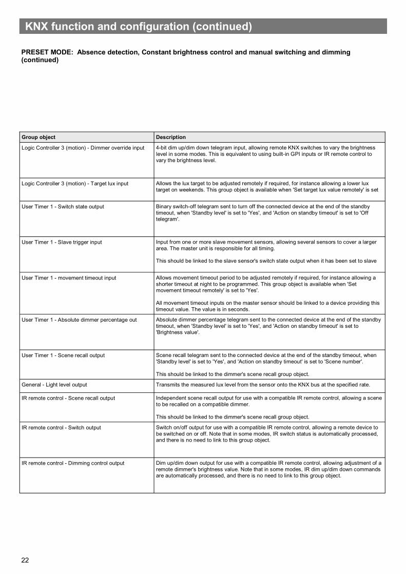
22
Group object Description
Logic Controller 3 (motion) - Dimmer override input 4-bit dim up/dim down telegram input, allowing remote KNX switches to vary the brightness
level in some modes. This is equivalent to using built-in GPI inputs or IR remote control to vary the brightness level.
Logic Controller 3 (motion) - Target lux input Allows the lux target to be adjusted remotely if required, for instance allowing a lower lux
target on weekends. This group object is available when 'Set target lux value remotely' is set
User Timer 1 - Switch state output Binary switch-off telegram sent to turn off the connected device at the end of the standby
timeout, when 'Standby level' is set to 'Yes', and 'Action on standby timeout' is set to 'Off telegram'.
User Timer 1 - Slave trigger input Input from one or more slave movement sensors, allowing several sensors to cover a larger
area. The master unit is responsible for all timing. This should be linked to the slave sensor's switch state output when it has been set to slave
User Timer 1 - movement timeout input Allows movement timeout period to be adjusted remotely if required, for instance allowing a
shorter timeout at night to be programmed. This group object is available when 'Set movement timeout remotely' is set to 'Yes'.
All movement timeout inputs on the master sensor should be linked to a device providing this
timeout value. The value is in seconds.
User Timer 1 - Absolute dimmer percentage out Absolute dimmer percentage telegram sent to the connected device at the end of the standby
timeout, when 'Standby level' is set to 'Yes', and 'Action on standby timeout' is set to 'Brightness value'.
User Timer 1 - Scene recall output Scene recall telegram sent to the connected device at the end of the standby timeout, when
'Standby level' is set to 'Yes', and 'Action on standby timeout' is set to 'Scene number'.
This should be linked to the dimmer's scene recall group object.
General - Light level output Transmits the measured lux level from the sensor onto the KNX bus at the specified rate.
IR remote control - Scene recall output Independent scene recall output for use with a compatible IR remote control, allowing a scene
to be recalled on a compatible dimmer.
This should be linked to the dimmer's scene recall group object.
IR remote control - Switch output Switch on/off output for use with a compatible IR remote control, allowing a remote device to
be switched on or off. Note that in some modes, IR switch status is automatically processed, and there is no need to link to this group object.
IR remote control - Dimming control output Dim up/dim down output for use with a compatible IR remote control, allowing adjustment of a
remote dimmer's brightness value. Note that in some modes, IR dim up/dim down commands are automatically processed, and there is no need to link to this group object.
KNX function and configuration (continued)
PRESET MODE: Absence detection, Constant brightness control and manual switching and dimming (continued)

23
Lights will be switched on when movement is detected, sw1 input is pressed momentarily and the measured lux level is below the set 'switch on threshold'. The lights will be switched off automatically when movement has ceased and the movement timeout period has elapsed. if the switch-on criteria have been satisfied the Constant brightness controller within the detector will aim to maintain a target lux value set by the user.
Group object Description
Logic Controller 1 (motion) - Switch state output Binary switch-on telegram sent to turn on connected device at start of controlled event, when
'Initial brightness level' is set to 'On telegram'.
This should be linked to the dimmer's on/off group object.
Logic Controller 1 (motion) - Slave trigger input Input from one or more slave movement sensors, allowing several sensors to cover a larger area.
The master unit is responsible for all timing. This should be linked to the slave sensor's switch state output when it has been set to slave
Logic Controller 1 (motion) - Movement timeout
input
Allows movement timeout period to be adjusted remotely if required, for instance allowing a
shorter timeout at night to be programmed. This group object is available when 'Set movement timeout remotely' is set to 'Yes'.
All movement timeout inputs on the master sensor should be linked to a device providing this
timeout value. The value is in seconds.
Logic Controller 1 (motion) - Absolute dimmer
percentage output
Percentage value sent to turn on connected device at start of controlled event, when 'Initial
brightness level' is set to 'Brightness value'.
This should be linked to the dimmer's absolute dimming (percentage) group object.
Logic Controller 1 (motion) - Scene recall output Scene number sent to turn on connected device at start of controlled event, when 'Initial
brightness level' is set to 'Scene number'.
This should be linked to the dimmer's scene recall group object.
Logic Controller 2 (motion) - Switch state output Binary switch-off telegram sent to turn off the connected device at the end of the controlled event,
when 'Standby level' is set to 'No'.
This should be linked to the dimmer's on/off group object.
Logic Controller 2 (motion) - Slave trigger input Input from one or more slave movement sensors, allowing several sensors to cover a larger area.
The master unit is responsible for all timing. This should be linked to the slave sensor's switch state output when it has been set to slave
Logic Controller 2 (motion) - Movement timeout
input
Allows movement timeout period to be adjusted remotely if required, for instance allowing a
shorter timeout at night to be programmed. This group object is available when 'Set movement timeout remotely' is set to 'Yes'.
All movement timeout inputs on the master sensor should be linked to a device providing this
timeout value. The value is in seconds.
Logic Controller 2 (motion) - Absolute dimmer
percentage output
Sets a standby illumination percentage at the end of the controlled event, rather than turning the
connected lights off. This requires 'Standby level' to be set to 'Yes'.
This should be linked to the dimmer's absolute dimming (percentage) group object.
Logic Controller 3 (motion) - Percentage output For modes incorporating either constant brightness control or manual dimming, this provides an
absolute percentage value for the controlled dimmer. Depending on the mode, it will be adjusted up and down to maintain a constant brightness, or a brightness level specified by the user via remote switch.
This should be linked to the dimmer's absolute dimming (percentage) group object.
PRESET MODE: Absence detection, Constant brightness control and lux switching
KNX function and configuration (continued)

24
Group object Description
Logic Controller 3 (motion) - Dimmer feedback
input
Feedback from the dimmer is used to determine a starting value for certain dimming and constant
brightness modes.
This should be linked to the dimmer's absolute (percentage) feedback group object if available.
Logic Controller 3 (motion) - Target lux input Allows the lux target to be adjusted remotely if required, for instance allowing a lower lux target
on weekends. This group object is available when 'Set target lux value remotely' is set to 'Yes'.
User Timer 1 - Switch state output Binary switch-off telegram sent to turn off the connected device at the end of the standby timeout,
when 'Standby level' is set to 'Yes', and 'Action on standby timeout' is set to 'Off telegram'.
This should be linked to the dimmer's on/off group object.
User Timer 1 - Slave trigger input Input from one or more slave movement sensors, allowing several sensors to cover a larger area.
The master unit is responsible for all timing. This should be linked to the slave sensor's switch state output when it has been set to slave
mode.
User Timer 1 - movement timeout input Allows movement timeout period to be adjusted remotely if required, for instance allowing a
shorter timeout at night to be programmed. This group object is available when 'Set movement timeout remotely' is set to 'Yes'.
All movement timeout inputs on the master sensor should be linked to a device providing this
timeout value. The value is in seconds.
User Timer 1 - Absolute dimmer percentage out Absolute dimmer percentage telegram sent to the connected device at the end of the standby
timeout, when 'Standby level' is set to 'Yes', and 'Action on standby timeout' is set to 'Brightness value'.
This should be linked to the dimmer's absolute dimming (percentage) group object.
User Timer 1 - Scene recall output Scene recall telegram sent to the connected device at the end of the standby timeout, when
'Standby level' is set to 'Yes', and 'Action on standby timeout' is set to 'Scene number'.
This should be linked to the dimmer's scene recall group object.
General - Light level output Transmits the measured lux level from the sensor onto the KNX bus at the specified rate.
IR remote control - Scene recall output Independent scene recall output for use with a compatible IR remote control, allowing a scene to
be recalled on a compatible dimmer.
This should be linked to the dimmer's scene recall group object.
IR remote control - Switch output Switch on/off output for use with a compatible IR remote control, allowing a remote device to be
switched on or off. Note that in some modes, IR switch status is automatically processed, and there is no need to link to this group object.
IR remote control - Dimming control output Dim up/dim down output for use with a compatible IR remote control, allowing adjustment of a
remote dimmer's brightness value. Note that in some modes, IR dim up/dim down commands are automatically processed, and there is no need to link to this group object.
KNX function and configuration (continued)
PRESET MODE: Absence detection, Constant brightness control and lux switching (continued)

25
Lights will be switched on when movement is detected, sw1 input is pressed momentarily and the measured lux level is below the set 'switch on threshold'. The lights will be switched off automatically when movement has ceased and the movement timeout period has elapsed, or if the measured lux level is above the set 'switch off threshold'
Group object Description
Logic Controller 1 (motion) - Switch state output Binary switch-on telegram sent to turn on connected device at start of controlled event, when
'Initial brightness level' is set to 'On telegram'.
This should be linked to the dimmer's on/off group object.
Logic Controller 1 (motion) - Slave trigger input Input from one or more slave movement sensors, allowing several sensors to cover a larger
area. The master unit is responsible for all timing. This should be linked to the slave sensor's switch state output when it has been set to slave
mode.
Logic Controller 1 (motion) - Movement timeout
input
Allows movement timeout period to be adjusted remotely if required, for instance allowing a
shorter timeout at night to be programmed. This group object is available when 'Set movement timeout remotely' is set to 'Yes'.
All movement timeout inputs on the master sensor should be linked to a device providing this
timeout value. The value is in seconds.
Logic Controller 1 (motion) - Absolute dimmer
percentage output
Percentage value sent to turn on connected device at start of controlled event, when 'Initial
brightness level' is set to 'Brightness value'.
This should be linked to the dimmer's absolute dimming (percentage) group object.
Logic Controller 1 (motion) - Scene recall output Scene number sent to turn on connected device at start of controlled event, when 'Initial
brightness level' is set to 'Scene number'.
This should be linked to the dimmer's scene recall group object.
Logic Controller 2 (motion) - Switch state output Binary switch-off telegram sent to turn off the connected device at the end of the controlled
event, when 'Standby level' is set to 'No'.
This should be linked to the dimmer's on/off group object.
Logic Controller 2 (motion) - Slave trigger input Input from one or more slave movement sensors, allowing several sensors to cover a larger
area. The master unit is responsible for all timing. This should be linked to the slave sensor's switch state output when it has been set to slave
mode.
Logic Controller 2 (motion) - Movement timeout
input
Allows movement timeout period to be adjusted remotely if required, for instance allowing a
shorter timeout at night to be programmed. This group object is available when 'Set movement timeout remotely' is set to 'Yes'.
All movement timeout inputs on the master sensor should be linked to a device providing this
timeout value. The value is in seconds.
Logic Controller 2 (motion) - Absolute dimmer
percentage output
Sets a standby illumination percentage at the end of the controlled event, rather than turning
the connected lights off. This requires 'Standby level' to be set to 'Yes'.
This should be linked to the dimmer's absolute dimming (percentage) group object.
User Timer 1 - Switch state output Binary switch-off telegram sent to turn off the connected device at the end of the standby
timeout, when 'Standby level' is set to 'Yes', and 'Action on standby timeout' is set to 'Off telegram'.
User Timer 1 - Slave trigger input Input from one or more slave movement sensors, allowing several sensors to cover a larger
area. The master unit is responsible for all timing. This should be linked to the slave sensor's switch state output when it has been set to slave
mode.
User Timer 1 - movement timeout input Allows movement timeout period to be adjusted remotely if required, for instance allowing a
shorter timeout at night to be programmed. This group object is available when 'Set movement timeout remotely' is set to 'Yes'.
All movement timeout inputs on the master sensor should be linked to a device providing this
User Timer 1 - Absolute dimmer percentage out Absolute dimmer percentage telegram sent to the connected device at the end of the standby
timeout, when 'Standby level' is set to 'Yes', and 'Action on standby timeout' is set to 'Brightness value'.
PRESET MODE: Absence detection and Lux switching
KNX function and configuration (continued)
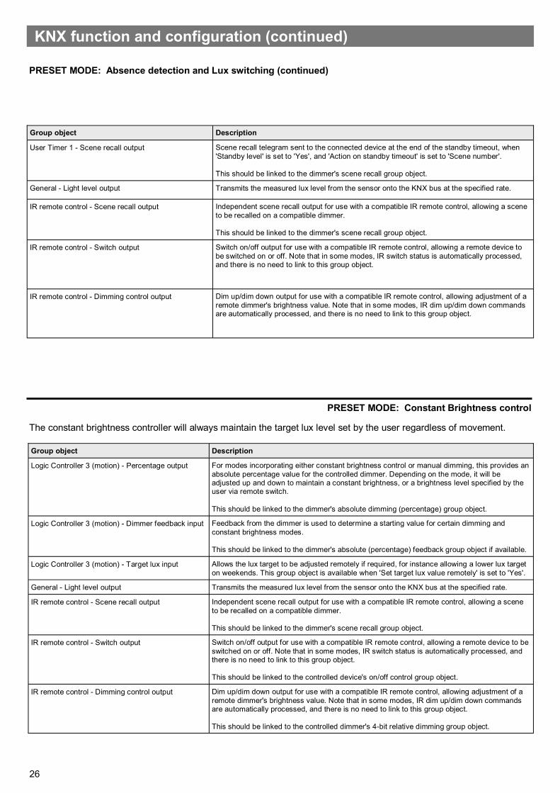
26
Group object Description
User Timer 1 - Scene recall output Scene recall telegram sent to the connected device at the end of the standby timeout, when
'Standby level' is set to 'Yes', and 'Action on standby timeout' is set to 'Scene number'.
This should be linked to the dimmer's scene recall group object.
General - Light level output Transmits the measured lux level from the sensor onto the KNX bus at the specified rate.
IR remote control - Scene recall output Independent scene recall output for use with a compatible IR remote control, allowing a scene
to be recalled on a compatible dimmer.
This should be linked to the dimmer's scene recall group object.
IR remote control - Switch output Switch on/off output for use with a compatible IR remote control, allowing a remote device to
be switched on or off. Note that in some modes, IR switch status is automatically processed, and there is no need to link to this group object.
IR remote control - Dimming control output Dim up/dim down output for use with a compatible IR remote control, allowing adjustment of a
remote dimmer's brightness value. Note that in some modes, IR dim up/dim down commands are automatically processed, and there is no need to link to this group object.
KNX function and configuration (continued)
The constant brightness controller will always maintain the target lux level set by the user regardless of movement.
Group object Description
Logic Controller 3 (motion) - Percentage output For modes incorporating either constant brightness control or manual dimming, this provides an
absolute percentage value for the controlled dimmer. Depending on the mode, it will be adjusted up and down to maintain a constant brightness, or a brightness level specified by the user via remote switch.
This should be linked to the dimmer's absolute dimming (percentage) group object.
Logic Controller 3 (motion) - Dimmer feedback input Feedback from the dimmer is used to determine a starting value for certain dimming and
constant brightness modes.
This should be linked to the dimmer's absolute (percentage) feedback group object if available.
Logic Controller 3 (motion) - Target lux input Allows the lux target to be adjusted remotely if required, for instance allowing a lower lux target
on weekends. This group object is available when 'Set target lux value remotely' is set to 'Yes'.
General - Light level output Transmits the measured lux level from the sensor onto the KNX bus at the specified rate.
IR remote control - Scene recall output Independent scene recall output for use with a compatible IR remote control, allowing a scene
to be recalled on a compatible dimmer.
This should be linked to the dimmer's scene recall group object.
IR remote control - Switch output Switch on/off output for use with a compatible IR remote control, allowing a remote device to be
switched on or off. Note that in some modes, IR switch status is automatically processed, and there is no need to link to this group object.
This should be linked to the controlled device's on/off control group object.
IR remote control - Dimming control output Dim up/dim down output for use with a compatible IR remote control, allowing adjustment of a
remote dimmer's brightness value. Note that in some modes, IR dim up/dim down commands are automatically processed, and there is no need to link to this group object.
This should be linked to the controlled dimmer's 4-bit relative dimming group object.
PRESET MODE: Constant Brightness control
PRESET MODE: Absence detection and Lux switching (continued)

27
The constant brightness controller will always maintain the target lux level set by the user regardless of movement, unless overridden by one of the switch inputs. The override is cleared when the 'manual override time' set by the user elapses. The lights can be switched on or off and dimmed up and down via a two position centre-biased retractive switch wired to sw1 and sw2. Sw1 input will send an On telegram when pressed momentarily or dim up when held. Sw2 input will send an off telegram when pressed momentarily or dim down when held.
Group object Description
Logic Controller 3 (motion) - Percentage output For modes incorporating either constant brightness control or manual dimming, this provides an
absolute percentage value for the controlled dimmer. Depending on the mode, it will be adjusted up and down to maintain a constant brightness, or a brightness level specified by the
user via remote switch.
Logic Controller 3 (motion) - Dimmer feedback input Feedback from the dimmer is used to determine a starting value for certain dimming and
constant brightness modes.
Logic Controller 3 (motion) - Target lux input Allows the lux target to be adjusted remotely if required, for instance allowing a lower lux target
on weekends.
General - Light level output Transmits the measured lux level from the sensor onto the KNX bus at the specified rate.
IR remote control - Scene recall output Independent scene recall output for use with a compatible IR remote control, allowing a scene
to be recalled on a compatible dimmer.
IR remote control - Switch output Switch on/off output for use with a compatible IR remote control, allowing a remote device to be
switched on or off. Note that in some modes, IR switch status is automatically processed, and
there is no need to link to this group object.
This should be linked to the controlled device's on/off control group object.
IR remote control - Dimming control output Dim up/dim down output for use with a compatible IR remote control, allowing adjustment of a
remote dimmer's brightness value. Note that in some modes, IR dim up/dim down commands
are automatically processed, and there is no need to link to this group object.
This should be linked to the controlled dimmer's 4-bit relative dimming group object.
Logic Controller 3 (motion) - Dimmer override input 4-bit dim up/dim down telegram input, allowing remote KNX switches to vary the brightness
level in some modes. This is equivalent to using built-in GPI inputs or IR remote control to vary
the brightness level.
PRESET MODE: Constant Brightness control and manual switching and dimming
KNX function and configuration (continued)

28
KNX function and configuration (continued)
The constant brightness controller will always maintain the target lux level set by the user regardless of movement, unless overridden by one of the switch inputs. The override is cleared when the 'manual override time' set by the user elapses. The lights can be switched on or off and dimmed up and down via a two position centre-biased retractive switch wired to sw1 and sw2. Sw1 input will send an On telegram when pressed momentarily or dim up when held. Sw2 input will send an off telegram when pressed momentarily or dim down when held. The lights will be switched OFF if the measured lux level is above the set 'switch off threshold'. The lights will remain off until the measured light level is below the 'switch on threshold'. If the lights have been switched off or held off due to lux no constant brightness telegrams will be sent.
Group object Description
Logic Controller 1 (motion) - Switch state output Binary switch-on telegram sent to turn on the connected device if the lux level is below the set
threshold.
This should be linked to the dimmer's on/off group object.
Logic Controller 2 (motion) - Switch state output Binary switch-off telegram sent to turn off the connected device if the lux level is above the set
threshold.
This should be linked to the dimmer's on/off group object.
Logic Controller 3 (motion) - Percentage output For modes incorporating either constant brightness control or manual dimming, this provides
an absolute percentage value for the controlled dimmer. Depending on the mode, it will be adjusted up and down to maintain a constant brightness, or a brightness level specified by the user via remote switch.
This should be linked to the dimmer's absolute dimming (percentage) group object.
Logic Controller 3 (motion) - Dimmer feedback input Feedback from the dimmer is used to determine a starting value for certain dimming and
constant brightness modes.
Logic Controller 3 (motion) - Target lux input Allows the lux target to be adjusted remotely if required, for instance allowing a lower lux target
on weekends. This group object is available when 'Set target lux value remotely' is set to 'Yes'.
General - Light level output Transmits the measured lux level from the sensor onto the KNX bus at the specified rate.
IR remote control - Scene recall output Independent scene recall output for use with a compatible IR remote control, allowing a scene
to be recalled on a compatible dimmer.
This should be linked to the dimmer's scene recall group object.
IR remote control - Switch output Switch on/off output for use with a compatible IR remote control, allowing a remote device to
be switched on or off. Note that in some modes, IR switch status is automatically processed, and there is no need to link to this group object.
This should be linked to the controlled device's on/off control group object.
IR remote control - Dimming control output Dim up/dim down output for use with a compatible IR remote control, allowing adjustment of a
remote dimmer's brightness value. Note that in some modes, IR dim up/dim down commands are automatically processed, and there is no need to link to this group object.
This should be linked to the controlled dimmer's 4-bit relative dimming group object.
PRESET MODE: Constant Brightness control, manual switching and dimming and lux switching
Lights will only be switched on if the measured lux level is below the set 'switch On threshold'. The lights will be switched OFF if the measured lux level is above the set 'switch off threshold'.
Group object Description
Logic Controller 1 (motion) - Switch state
output
Binary switch-on telegram sent to turn on the connected device if the lux level is below the set threshold.
This should be linked to the dimmer's on/off group object.
Logic Controller 2 (motion) - Switch state
output
Binary switch-off telegram sent to turn off the connected device if the lux level is above the set threshold.
This should be linked to the dimmer's on/off group object.
General - Light level output Transmits the measured lux level from the sensor onto the KNX bus at the specified rate.
IR remote control - Scene recall output Independent scene recall output for use with a compatible IR remote control, allowing a scene to be
recalled on a compatible dimmer.
IR remote control - Switch output Switch on/off output for use with a compatible IR remote control, allowing a remote device to be switched
on or off. Note that in some modes, IR switch status is automatically processed, and there is no need to link to this group object.
IR remote control - Dimming control output Dim up/dim down output for use with a compatible IR remote control, allowing adjustment of a remote
dimmer's brightness value. Note that in some modes, IR dim up/dim down commands are automatically processed, and there is no need to link to this group object.
PRESET MODE: Lux switching

29
Lights will only be switched on if the measured lux level is below the set 'switch On threshold'. The lights will be switched OFF if the measured lux level is above the set 'switch off threshold'. The lights can be switched on or off and dimmed up and down via a two position centre-biased retractive switch wired to sw1 and sw2. Sw1 input will send an On tele-gram when pressed momentarily or dim up when held. Sw2 input will send an off telegram when pressed momentarily or dim down when held. Note if the lights are switched on/off or dimmed via the switch the lux switching is overridden. The override is cleared when the manual override time elapses.
Group object Description
Logic Controller 1 (motion) - Switch state output Binary switch-on telegram sent to turn on the connected device if the lux level is below the set
threshold.
Logic Controller 2 (motion) - Switch state output Binary switch-off telegram sent to turn off the connected device if the lux level is above the set
threshold.
Logic Controller 3 (motion) - Percentage output For modes incorporating either constant brightness control or manual dimming, this provides an
absolute percentage value for the controlled dimmer. Depending on the mode, it will be adjusted up and down to maintain a constant brightness, or a brightness level specified by the user via remote switch.
This should be linked to the dimmer's absolute dimming (percentage) group object.
Logic Controller 3 (motion) - Dimmer feedback input Feedback from the dimmer is used to determine a starting value for certain dimming and
constant brightness modes.
This should be linked to the dimmer's absolute (percentage) feedback group object if available.
Logic Controller 3 (motion) - Dimmer override input 4-bit dim up/dim down telegram input, allowing remote KNX switches to vary the brightness
level in some modes. This is equivalent to using built-in GPI inputs or IR remote control to vary the brightness level.
General - Light level output Transmits the measured lux level from the sensor onto the KNX bus at the specified rate.
IR remote control - Scene recall output Independent scene recall output for use with a compatible IR remote control, allowing a scene
to be recalled on a compatible dimmer.
This should be linked to the dimmer's scene recall group object.
IR remote control - Switch output Switch on/off output for use with a compatible IR remote control, allowing a remote device to be
switched on or off. Note that in some modes, IR switch status is automatically processed, and there is no need to link to this group object.
IR remote control - Dimming control output Dim up/dim down output for use with a compatible IR remote control, allowing adjustment of a
remote dimmer's brightness value. Note that in some modes, IR dim up/dim down commands are automatically processed, and there is no need to link to this group object.
PRESET MODE: Lux Switching and manual switching and dimming
KNX function and configuration (continued)

30
Select one of the 4 switch types, two pole retractive centre off, two pole latching centre off, single pole retractive push to make, single pole latching push to make. Simply link the group objects to allow on/off or dim up/down functionality de-pending on the switch type selected.
Group object Description
Switch Inputs - Switch 1 state output Binary switch-on/off telegram sent to turn on/off the connected device if the switch is pressed.
Switch Inputs - Switch 2 state output Binary switch-off telegram sent to turn off the connected device if the switch is pressed.
Switch Inputs - Switch 1 dimming control output Depending on the switch type selected this group object is used to send Dim up/down telegrams to
Switch Inputs - Switch 2 dimming control output Depending on the switch type selected this group object is used to send Dim down telegrams to the
IR remote control - Scene recall output Independent scene recall output for use with a compatible IR remote control, allowing a scene to be
recalled on a compatible dimmer.
IR remote control - Switch output Switch on/off output for use with a compatible IR remote control, allowing a remote device to be
switched on or off. Note that in some modes, IR switch status is automatically processed, and there is no need to link to this group object.
IR remote control - Dimming control output Dim up/dim down output for use with a compatible IR remote control, allowing adjustment of a
remote dimmer's brightness value. Note that in some modes, IR dim up/dim down commands are automatically processed, and there is no need to link to this group object.
To be used in conjunction with a 'master' and/ or multiple slave sensors. The detector will send out On telegrams when movement is detected. No telegram will be sent when movement has cleared, this is sent by the master sensor.
Group object Description
Logic Controller 1 (motion) - Switch state output Binary switch-on telegram sent to re/trigger the master detector.
IR remote control - Scene recall output Independent scene recall output for use with a compatible IR remote control, allowing a scene to
be recalled on a compatible dimmer.
This should be linked to the dimmer's scene recall group object.
IR remote control - Switch output Switch on/off output for use with a compatible IR remote control, allowing a remote device to be
switched on or off. Note that in some modes, IR switch status is automatically processed, and there is no need to link to this group object.
IR remote control - Dimming control output Dim up/dim down output for use with a compatible IR remote control, allowing adjustment of a
remote dimmer's brightness value. Note that in some modes, IR dim up/dim down commands are automatically processed, and there is no need to link to this group object.
PRESET MODE: Manual switching
PRESET MODE: Slave
KNX function and configuration (continued)

31
Four ETS-configurable logic controllers allow the installer to fine-tune the behaviour of the detector in response to sen-sor state, switch inputs and KNX group objects offering a level of control that would normally require an external logic block.
The various functions are grouped in ETS as follows:
General settings
Basic settings such as walk test LED enable/disable, sensor sensitivity, movement timeout and light sensor cali-bration.
Switch inputs
Defines the behaviour when each of the switch inputs change state, e.g. dimming, switching or scene recall. Switch inputs may also be used as inputs to the three logic controllers.
Infrared scene control
Defines which KNX scenes are mapped to the scene recall button on the UHS7 remote control, and how the on/off buttons should behave.
Logic controller 1/2 (switch/scene)
Defines a custom logic function using simple drop-down boxes to send either switch or scene recall telegrams in response to the state of various inputs, sensor state and KNX group objects.
Logic controller 3/4 (brightness)
Defines a custom logic function using simple drop-down boxes to determine a brightness target value that should be maintained. The logic function may use various inputs, sensor state and KNX group objects to determine which brightness target should be active.
User timer 1/2
Each timer can be configured with up to two logic functions: one to start the timer, and one to stop it. The timer period can be independently set, and commands can be sent when the timer starts, is stopped or when the time period expires.
Basic trigger for alarm security and slave sensors
Raw switch output from the movement detector, suitable for signalling security systems or master sensors when used in master-slave mode.
Advanced mode
KNX function and configuration (continued)

32
KNX function and configuration (continued)
Setting Options Description
Sensor walk test LED Disable
Enable
Enable or disable the sensor walk test LED, triggered when movement is
detected. This is useful for commissioning, (or if the detector is to be used in bedrooms). Note that the walk test function can also be turned on and off via infrared remote control.
Sensor sensitivity 0 to 9 Increase or decrease the detector's sensitivity to movement. 0 is least
sensitive, 9 is most sensitive. The sensitivity can be overridden via infrared remote, but will be overwritten when parameters are updated via ETS.
Lux multiplier Floating point Value to multiply raw light level readings by to obtain true lux value. In
practice, this will need to be set with the aid of a light meter in the environment that the detector is used in, as reflected light and even choice of furnishings will dramatically affect the readings obtained.
Send light level telegrams every 0 – 65535s Defines how often to send light level telegrams. It is only possible to send
cyclically: immediate transmission would overload the bus.
Light Level Transmission mode Send Light level telegrams every...
Send on light level change
Defines the transmission mode for sending light level telegrams over the
KNX bus
Group Object Data Type Description
Light level output 9.4 DPT_Value_Lux Simple cyclical output of current brightness in lux.
ADVANCED MODE: General settings
The general configuration tab contains settings which relate to general operation of the detector, such as sensitivity, timeouts and whether the walk test LED should be enabled or disabled. Settings made in this section will also affect inputs to the various controllers detailed below, with the exception of the basic movement detection controller.
The detector contains a light sensor for use as part of the constant brightness controller, and to send light level readings to other devices on the KNX bus. It is important to note that the light sensor requires calibration in order to produce real lux values, and this calibration should take place once installed using a light meter.
To perform a calibration, the light level multiplier should initially be set to 1.0. The room should be furnished as reflected light (e.g. from uncovered floor tiles) will dramatically change the measured value. Using the ETS group monitor, record several lux values for different levels of illumination, with the light meter placed normally within the room. It will be necessary to assign a group address to the light level output group object.
Once these values have been recorded, the multiplier can be calculated as follows:
Light meter value Detector value Calculated Multiplier
590 534 1.105
928 816 1.137
Multiplier = lightmetervalue
detectorvalue For example.
An average of the calculated multiplier values yields a multiplier of 1.121.
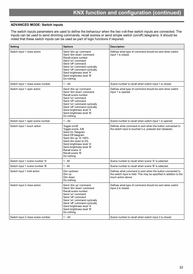
33
The switch inputs parameters are used to define the behaviour when the two volt-free switch inputs are connected. The inputs can be used to send dimming commands, recall scenes or send simple switch (on/off) telegrams. It should be noted that these switch inputs can be used as part of logic functions if required.
Setting Options Description
Switch input 1 close action Send 'dim up' command Send 'dim down' command
Recall scene number Send 'on' command Send 'off' command
Send 'on' command cyclically Send 'off' command cyclically Send brightness level ‘A’
Send brightness level ‘B’ Do nothing
Defines what type of command should be sent when switch input 1 is closed.
Switch input 1 close scene number 1 – 64 Scene number to recall when switch input 1 is closed
Switch input 1 open action Send 'dim up' command Send 'dim down' command
Recall scene number Send 'on' command Send 'off' command
Send 'on' command cyclically Send 'off' command cyclically Send brightness level ‘A’
Send brightness level ‘B’ Do nothing
Defines what type of command should be sent when switch input 1 is opened.
Switch input 1 open scene number 1 – 64 Scene number to recall when switch input 1 is opened.
Switch input 1 touch action Toggle on/off Toggle scene A/B
Send On Telegram Send Off telegram Send dim up 10 100%
Send dim down to 0% Send brightness level ‘A’ Send brightness level ‘B’
Recall scene ‘A’ Recall scene ‘B’ Do nothing
Defines what command is sent when the button connected to the switch input is touched (i.e. pressed and released)
Switch input 1 scene number 'A’ 1 - 64 Scene number to recall when scene 'A' is selected.
Switch input 1 scene number 'B’ 1 - 64 Scene number to recall when scene 'B' is selected.
Switch input 1 hold action Dim up/down Dim up
Dim down Do nothing
Defines what command is sent when the button connected to the switch input is held. This may be specified in addition to the
touch action above
Switch input 2 close action Send 'dim up' command Send 'dim down' command
Recall scene number Send 'on' command Send 'off' command
Send 'on' command cyclically Send 'off' command cyclically Send brightness level ‘A’
Send brightness level ‘B’ Do nothing
Defines what type of command should be sent when switch input 2 is closed.
Switch input 2 close scene number 1 – 64 Scene number to recall when switch input 2 is closed.
ADVANCED MODE: Switch inputs
KNX function and configuration (continued)

34
Setting Options Description
Switch input 2 open action Send 'dim up' command Send 'dim down' command
Recall scene number Send 'on' command Send 'off' command
Send 'on' command cyclically Send 'off' command cyclically Send brightness level ‘A’
Send brightness level ‘B’ Do nothing
Defines what type of command should be sent when switch input 2 is opened.
Switch input 2 open scene number 1 – 64 Scene number to recall when switch input 2 is opened.
Switch input 2 touch action Toggle on/off Toggle scene A/B
Send On Telegram Send Off telegram Send dim up 10 100%
Send dim down to 0% Send brightness level ‘A’ Send brightness level ‘B’
Recall scene ‘A’ Recall scene ‘B’ Do nothing
Defines what command is sent when the button connected to the switch input is touched (i.e. pressed and released)
Switch input 2 scene number 'A’ 1 - 64 Scene number to recall when scene 'A' is selected.
Switch input 2 scene number 'B’ 1 - 64 Scene number to recall when scene 'B' is selected.
Switch input 2 hold action Dim up/down Dim up
Dim down Do nothing
Defines what command is sent when the button connected to the switch input is held. This may be specified in addition to the touch
action above
Dim up/dim down step percentage 100% 50%
25% 12.5% 6.25%
3.125% 1.5625%
The percentage to add or subtract from the current dimmer value when the relevant button is pressed. Smaller percentages offer
finer-grained control, but require the user to press the button more times to change the light level.
Send switch 1 cyclical telegrams every 0 – 65535s Defines how often to send switch state telegrams if cyclical sending has been chosen.
Send switch 2 cyclical telegrams every 0 – 65535s Defines how often to send switch state telegrams if cyclical sending
has been chosen.
Update Repeat interval when button is held
0 – 65535ms Defines the period of time between repeat dimming telegrams. i.e. When the button is held. Can be used to speed up or slow
down the manual dimming process.
Switch 1 scene recall 17.1 DPT_SceneNumber Scene number transmitted when switch 1 changes state if in scene recall mode.
Switch 2 scene recall 17.1 DPT_SceneNumber Scene number transmitted when switch 2 changes state if in scene recall mode.
Switch 1 state output 1.1 DPT_Switch On/off switch state telegram if configured.
Switch 2 state output 1.1 DPT_Switch On/off switch state telegram if configured.
Switch 1 dimming control output' 3.7 DPT_Control_Dimming Dimming control output if switches are configured for dim up/dim down operation.
Switch 2 dimming control output' 3.7 DPT_Control_Dimming Dimming control output if switches are configured for dim up/dim down operation.
KNX function and configuration (continued)
ADVANCED MODE: Switch inputs (continued)

35
The infrared scene control parameters are used to configure the scene recall behaviour when the sensor is used with the UHS7 remote control handset. This handset provides eight scene recall buttons, dim up/down buttons and on/off buttons. As KNX defines a maximum of 64 scenes per group object, the parameter page allows these scenes to be mapped to the 8 remote control buttons.
In addition, the on/off buttons may be used to transmit a simple switch telegram, or alternatively used to recall an additional two scenes. This would allow the 'off' scene to preserve a low level of light at all times.
Dim up/dim down buttons are provided for direct control of the dimmer; the dimming interval may also be set. Note that variations to brightness using this method will not be 'saved' by the dimmer; subsequent scene recalls will revert to programmed values.
Setting Options Description
On/off button command type Switch Scene Recall
Defines whether the on/off buttons should be used to send switch or scene recall telegrams
Map 'on' button to scene 1 – 64 Scene number to be associated with 'on' button
Map 'off' button to scene 1 – 64 Scene number to be associated with 'off' button
Map button 1 to scene 1 – 64 Scene number to be associated with IR button 1
Map button 2 to scene 1 – 64 Scene number to be associated with IR button 2
Map button 3 to scene 1 – 64 Scene number to be associated with IR button 3
Map button 4 to scene 1 – 64 Scene number to be associated with IR button 4
Map button 5 to scene 1 – 64 Scene number to be associated with IR button 5
Map button 6 to scene 1 – 64 Scene number to be associated with IR button 6
Map button 7 to scene 1 – 64 Scene number to be associated with IR button 7
Map button 8 to scene 1 – 64 Scene number to be associated with IR button 8
Dim up/dim down step percentage 100% 50%
25% 12.5% 6.25%
3.125% 1.5625%
The percentage to add or subtract from the current dimmer value. Smaller percentages offer finer-
grained control, but require the user to press the
button more times to change the light level
Group Object Data Type Description
Scene recall output 17.1 DPT_SceneNumber Scene number transmitted when IR scene ‘Button is pressed, or on/off buttons in
scene recall mode.
Switch output 1.1 DPT_Switch Switch on/off telegram transmitted when IR on/off buttons are pressed.
Dimming control output 3.7 DPT_Control_Dimming Dimming telegram transmitted when IR dim up/dim down buttons are pressed. The
increment can be configured by the installer.
ADVANCED MODE: Infrared scene control
KNX function and configuration (continued)
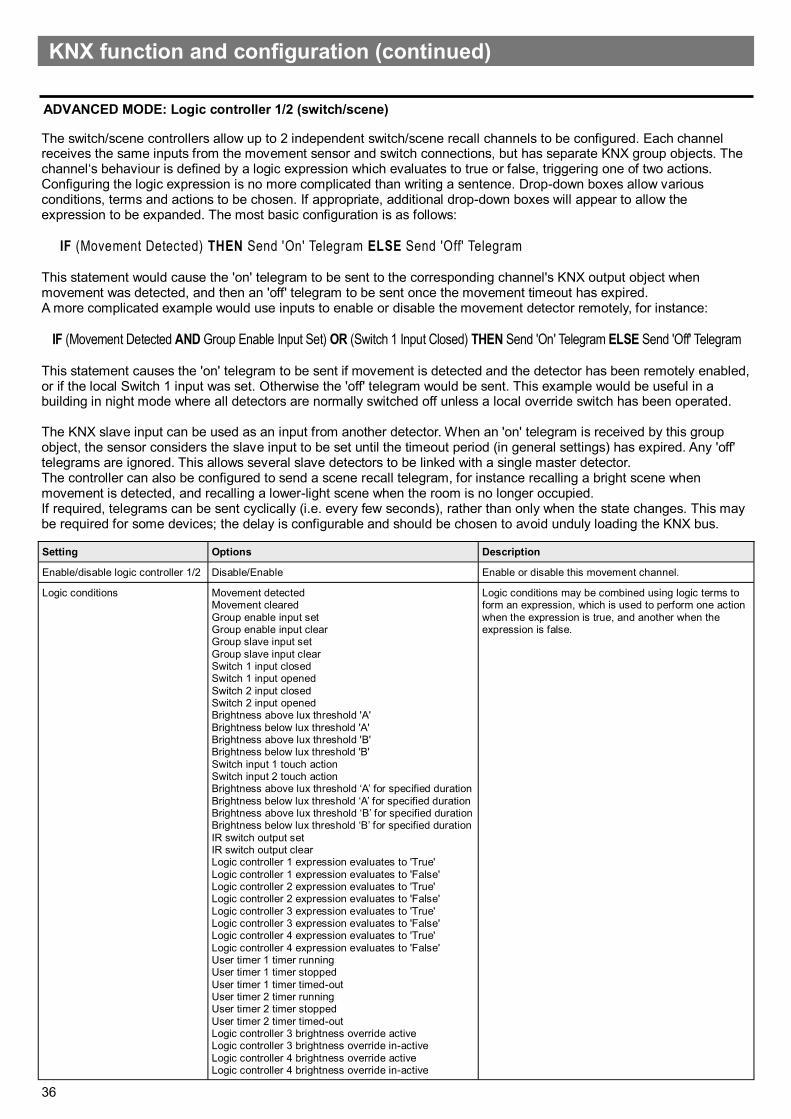
36
The switch/scene controllers allow up to 2 independent switch/scene recall channels to be configured. Each channel receives the same inputs from the movement sensor and switch connections, but has separate KNX group objects. The channel‘s behaviour is defined by a logic expression which evaluates to true or false, triggering one of two actions. Configuring the logic expression is no more complicated than writing a sentence. Drop-down boxes allow various conditions, terms and actions to be chosen. If appropriate, additional drop-down boxes will appear to allow the expression to be expanded. The most basic configuration is as follows:
IF (Movement Detected) THEN Send 'On' Telegram ELSE Send 'Off' Telegram This statement would cause the 'on' telegram to be sent to the corresponding channel's KNX output object when movement was detected, and then an 'off' telegram to be sent once the movement timeout has expired. A more complicated example would use inputs to enable or disable the movement detector remotely, for instance:
IF (Movement Detected AND Group Enable Input Set) OR (Switch 1 Input Closed) THEN Send 'On' Telegram ELSE Send 'Off' Telegram
This statement causes the 'on' telegram to be sent if movement is detected and the detector has been remotely enabled, or if the local Switch 1 input was set. Otherwise the 'off' telegram would be sent. This example would be useful in a building in night mode where all detectors are normally switched off unless a local override switch has been operated. The KNX slave input can be used as an input from another detector. When an 'on' telegram is received by this group object, the sensor considers the slave input to be set until the timeout period (in general settings) has expired. Any 'off' telegrams are ignored. This allows several slave detectors to be linked with a single master detector. The controller can also be configured to send a scene recall telegram, for instance recalling a bright scene when movement is detected, and recalling a lower-light scene when the room is no longer occupied. If required, telegrams can be sent cyclically (i.e. every few seconds), rather than only when the state changes. This may be required for some devices; the delay is configurable and should be chosen to avoid unduly loading the KNX bus.
Setting Options Description
Enable/disable logic controller 1/2 Disable/Enable Enable or disable this movement channel.
Logic conditions Movement detected Movement cleared
Group enable input set Group enable input clear Group slave input set
Group slave input clear Switch 1 input closed Switch 1 input opened
Switch 2 input closed Switch 2 input opened Brightness above lux threshold 'A'
Brightness below lux threshold 'A' Brightness above lux threshold 'B' Brightness below lux threshold 'B'
Switch input 1 touch action Switch input 2 touch action Brightness above lux threshold ‘A’ for specified duration
Brightness below lux threshold ‘A’ for specified duration Brightness above lux threshold ‘B’ for specified duration Brightness below lux threshold ‘B’ for specified duration
IR switch output set IR switch output clear Logic controller 1 expression evaluates to 'True'
Logic controller 1 expression evaluates to 'False' Logic controller 2 expression evaluates to 'True' Logic controller 2 expression evaluates to 'False'
Logic controller 3 expression evaluates to 'True' Logic controller 3 expression evaluates to 'False' Logic controller 4 expression evaluates to 'True'
Logic controller 4 expression evaluates to 'False' User timer 1 timer running User timer 1 timer stopped
User timer 1 timer timed-out User timer 2 timer running User timer 2 timer stopped
User timer 2 timer timed-out Logic controller 3 brightness override active Logic controller 3 brightness override in-active
Logic controller 4 brightness override active Logic controller 4 brightness override in-active
Logic conditions may be combined using logic terms to form an expression, which is used to perform one action
when the expression is true, and another when the expression is false.
ADVANCED MODE: Logic controller 1/2 (switch/scene)
KNX function and configuration (continued)

37
Group Object Data Type Description
Logic controller 1 (motion) - Switch state output 1.1 DPT_Switch The main output from the channel's logic expression.
Logic controller 1 (motion) - Scene recall output 17.1 DPT_SceneNumber Configured scene number is sent via this group object if required.
Logic controller 1 (motion) - Enable input 1.3 DPT_Enable Global enable/disable input for this channel allowing remote
devices to participate in the logic function.
Logic controller 1 (motion) - Slave trigger input 1.1 DPT_Switch Slave input for this channel, allowing the state of other detectors
to be read as part of the logic function.
Logic controller 1 (motion) - Movement timeout input 7.5 DPT_TimePeriodSec Allows a remote device to change the movement
timeout, if this option is selected. The value must be in seconds.
Logic controller 1 (motion) - Absolute dimmer
percentage
5.4 DPT_Percent_U8 Configured dimmer percentage is sent via this group
object if required.
Logic controller 2 (motion) - Switch state output 1.1 DPT_Switch The main output from the channel's logic expression.
Logic controller 2 (motion) - Scene recall output 17.1 DPT_SceneNumber Configured scene number is sent via this group object if required.
Logic controller 2 (motion) - Enable input 1.3 DPT_Enable Global enable/disable input for this channel allowing remote
devices to participate in the logic function.
Logic controller 2 (motion) - Slave trigger input 1.1 DPT_Switch Slave input for this channel, allowing the state of other detectors
to be read as part of the logic function.
Logic controller 2 (motion) - Movement timeout input 7.5 DPT_TimePeriodSec Allows a remote device to change the movement
timeout, if this option is selected. The value must be in seconds.
Logic controller 2 (motion) - Absolute dimmer
percentage
5.4 DPT_Percent_U8 Configured dimmer percentage is sent via this group
object if required.
Setting Options Description
Logic terms AND OR
THEN
Logic terms are used to define the function. The AND term indicates that ALL inputs must be true for the expression to be
true, whereas the OR term will return true if one of the inputs is true. The THEN term is used to indicate that the expression is complete, and that the next item is an action.
Logic actions Send 'on' telegram Send 'off' telegram
Send 'on' telegram cyclically Send 'off' telegram cyclically Recall scene 'A'
Recall scene 'B' Set brightness level ‘A' Set brightness level ‘B
Send nothing
When the logic expression is evaluated, an action may be associated with both the if-then and else portions of the
expression, i.e. Send 'on' telegram if the expression is true, else Send 'off' telegram.
Movement timeout source ETS parameter or Group object Movement timeout may be set statically using ETS, or alternatively may be changed by other devices on the KNX bus
Movement timeout 0 – 32767 secs, 0 - 546 mins, 0 - 9hrs
How long to wait after the last movement is detected before signalling a 'movement cleared' state
Brightness threshold ‘A’ Floating point Lux value to be used as comparison value in logic function, e.g. above or below this value.
Brightness threshold ‘B’ Floating point Lux value to be used as comparison value in logic function, e.g. above or below this value.
Scene 'A' 1 - 64 KNX scene number to be recalled on command.
Scene 'B' 1 - 64 KNX scene number to be recalled on command..
Brightness setting 'A' 0 - 100% The brightness percentage to send to the dimmer when required.
Brightness setting 'B' 0 - 100% The brightness percentage to send to the dimmer when required.
Send cyclical telegrams every 0 – 65535s How often to send cyclical telegrams if selected as part of the logic function.
Trigger Duration 0-32767 secs, 0-546 mins, 0-9 hours
Defines how long the measured light level has to be above/ below the brightness threshold (A/B) before an action is
performed.
Brightness Level ‘A’ 0-100% Defines the brightness level to send to the dimmer when required
Brightness Level ‘B’ 0-100% Defines the brightness level to send to the dimmer when required
Delay before sending action 0-32767 secs, 0-546 mins, 0-9 hours
Defines how long to delay the output before an action is sent
ADVANCED MODE: Logic controller 1/2 (switch/scene) (continued)
KNX function and configuration (continued)

38
The brightness logic controller aims to maintain a uniform brightness in the sensor area at all times (known as daylight linking, daylight harvesting or maintained illuminance). Two brightness targets can be defined, subject to a successful calibration (as detailed earlier). In similar fashion to the movement controllers, a logic expression can be constructed to choose which brightness target the controller should try to achieve. This would allow the lights to be turned off overnight, or for the lights to be made brighter when the room is occupied. The controller sends an 8-bit absolute percentage value to the dimmer. The installer may choose suitable values for the dimming increment and interval: these values should be chosen to minimise dimmer oscillation and response time. A deadband setting prevents the controller from making unnecessary adjustments. It is also possible to set a brightness target via a KNX group object, allowing the brightness target to be controlled from elsewhere. This might be useful in combination with a room reservations system, or to make the lights dimmer at weekends. Dimming telegrams are sent when required by the controller; the controller will not send dimming telegrams when the measured light level is close to the target value, subject to the deadband setting, or if in the override state.
Setting Options Description
Enable/disable logic controller 3 Disable Enable
Enable or disable the logic controller function.
Logic conditions Movement detected Movement cleared Group enable input set Group enable input clear Group slave input set Group slave input clear Switch 1 input closed Switch 1 input opened Switch 2 input closed Switch 2 input opened Switch input 1 touch action Switch input 2 touch action Brightness above lux threshold ‘A’ for specified duration Brightness below lux threshold ‘A’ for specified duration Brightness above lux threshold ‘B’ for specified duration Brightness below lux threshold ‘B’ for specified duration IR switch output set IR switch output clear Logic controller 1 expression evaluates to 'True' Logic controller 1 expression evaluates to 'False' Logic controller 2 expression evaluates to 'True' Logic controller 2 expression evaluates to 'False' Logic controller 3 expression evaluates to 'True' Logic controller 3 expression evaluates to 'False' Logic controller 4 expression evaluates to 'True' Logic controller 4 expression evaluates to 'False' User timer 1 timer running User timer 1 timer stopped User timer 1 timer timed-out User timer 2 timer running User timer 2 timer stopped User timer 2 timer timed-out Dimmer override active Dimmer override not active
Logic conditions may be combined using logic terms to form an expression, which is used to perform one action when the expression is true, and another when the expression is false.
Logic terms AND OR THEN
Logic terms are used to define the function. The AND term indicates that ALL inputs must be true for the expression to be true, whereas the OR term will return true if one of the inputs is true. The THEN term is used to indicate that the expression is complete, and that the next item is an action.
Logic actions Set brightness target A Set brightness target B Set remote brightness target Set dimmer on Set dimmer off Set absolute dimmer level Do nothing
When the logic expression is evaluated, an action may be associated with both the if-then and else portions of the expression, i.e. Set brightness target 1 if the expression is true, else Set brightness target 2.
Movement timeout source ETS parameter or Group object Movement timeout may be set statically using ETS, or alternatively may be changed by other devices on the KNX bus
Movement timeout 0 – 32767 secs, 0 - 546 mins, 0 - 9hrs How long to wait after the last movement is detected before signalling a 'movement cleared' state
Brightness target A Floating point Target value in lux for the brightness controller to aim for.
Brightness target B Floating point Target value in lux for the brightness controller to aim for.
Telegram interval 0 – 65535 milliseconds How often to send commands to the dimmer when varying the brightness.
ADVANCED MODE: Logic controller 3/4 (brightness)
KNX function and configuration (continued)

39
Group Object Data Type Description
Percentage output 5.4 DPT_Percent_U8 Brightness control for connected dimmer. The constant brightness controller will increase or decrease this value depending on the target selected
Enable input 1.3 DPT_Enable Global enable/disable input for this channel allowing remote devices to participate in the logic function.
Slave trigger input 1.1 DPT_Switch Slave input for this channel, allowing the state of other detectors to be read as part of the logic function.
Movement timeout input 7.5 DPT_TimePeriodSec Allows a remote device to change the movement timeout, if this option is selected. The value must be in seconds.
Target lux input 9.4 DPT_Value_Lux Brightness target value set by an external device, rather than an internal preset
Target lux output 9.4 DPT_Value_Lux Brightness target value selected by logic function, for use by other devices.
Dimmer override input Dimming control Allows an external KNX switch to override the brightness controller
Setting Options Description
Dimming increment 100% 50% 25% 12.5% 6.25% 3.125% 1.5625%
The amount by which each subsequent dimming telegram raises or lowers the light level. Typically a small value will be used here, but will depend on the environment. Large values may cause the dimmer to oscillate between light and dark.
Dimming deadband Floating point Deadband value in lux within which the controller will not attempt to vary the light output.
Brightness threshold ‘A’ Floating point Lux value to be used as comparison value in logic function, e.g. above or below this value.
Trigger Duration 0-32767 secs, 0-546 mins, 0-9 hours Defines how long the measured light level has to be above/ below the brightness threshold (A/B) before an action is performed.
Brightness threshold ‘B’ Floating point Lux value to be used as comparison value in logic function, e.g. above or below this value.
Trigger Duration 0-32767 secs, 0-546 mins, 0-9 hours Defines how long the measured light level has to be above/ below the brightness threshold (A/B) before an action is performed.
Starting % source for 'THEN' condition Last value sent to dimmer Preset Value, 0-100% Remote dimmer feedback input
Define the percentage for the brightness controller to start from when the expression evaluates to true.
Starting % source for ‘ELSE' condition Last value sent to dimmer Preset Value, 0-100% Remote dimmer feedback input
Define the percentage for the brightness controller to start from when the expression evaluates to false.
Control source for dimmer override Dimmer override input GPI switches Infra red remote control
Dimmer, GPI and infra red inputs Override disabled
Select, if applicable the override source for the constant brightness controller, telegrams sent from the control source will override the constant
brightness controller. The override is cleared when the controller changes state.
Absolute dimmer level 0-100% Defines the brightness level to send to the dimmer when required
ADVANCED MODE: Logic controller 3/4 (brightness)
(continued)
KNX function and configuration (continued)

40
Two user-configurable timers may be used to send commands based on timed events. Each timer may be started and stopped using independent logic expressions, for instance starting a timer when movement is detected, and stopping it if a final exit switch is closed. Once started, a timer will run until it expires, or is stopped. If the 'start' condition is matched again (for instance, additional motion is detected), then the time period will be reset.
Commands may be attached to three timer events: timer start, timer stop and timeout. These commands may be used to switch a remote device on or off, set a scene or set a brightness level. It is possible to use both timers together to achieve a three-stage illumination profile.
Setting Options Description
Timer start logic expression Movement detected Movement cleared
Group enable input set Group enable input clear Group slave input set
Group slave input clear Switch 1 input closed Switch 1 input opened
Switch 2 input closed Switch 2 input opened Brightness above lux threshold 'A'
Brightness below lux threshold 'A' Brightness above lux threshold 'B' Brightness below lux threshold 'B'
Switch input 1 touch action Switch input 2 touch action Brightness above lux threshold ‘A’ for specified duration
Brightness below lux threshold ‘A’ for specified duration Brightness above lux threshold ‘B’ for specified duration Brightness below lux threshold ‘B’ for specified duration
IR switch output set IR switch output clear Logic controller 1 expression evaluates to 'True'
Logic controller 1 expression evaluates to 'False' Logic controller 2 expression evaluates to 'True' Logic controller 2 expression evaluates to 'False'
Logic controller 3 expression evaluates to 'True' Logic controller 3 expression evaluates to 'False' Logic controller 4 expression evaluates to 'True'
Logic controller 4 expression evaluates to 'False' User timer 1 timer running User timer 1 timer stopped
User timer 1 timer timed-out User timer 2 timer running User timer 2 timer stopped
User timer 2 timer timed-out Logic controller 3 brightness override active Logic controller 3 brightness override in-active
Logic controller 4 brightness override active Logic controller 4 brightness override in-active
Logic conditions may be combined using logic terms to form an expression which, when true, starts (or restarts) the timer.
There is no action when the expression evaluates to false.
Logic terms AND OR
THEN
Logic terms are used to define the function. The AND term indicates that ALL inputs must be true for the expression to
be true, whereas the OR term will return true if one of the inputs is true. The THEN term is used to indicate that the expression is complete, and that the next item is an action.
Timer stop logic expression Movement detected Movement cleared Group enable input set Group enable input clear Group slave input set Group slave input clear Switch 1 input closed Switch 1 input opened Switch 2 input closed Switch 2 input opened Brightness above lux threshold 'A' Brightness below lux threshold 'A'
Brightness above lux threshold 'B' Brightness below lux threshold 'B' Switch input 1 touch action
Switch input 2 touch action Brightness above lux threshold ‘A’ for specified duration Brightness below lux threshold ‘A’ for specified duration
Brightness above lux threshold ‘B’ for specified duration Brightness below lux threshold ‘B’ for specified duration IR switch output set
IR switch output clear
Logic conditions may be combined using logic terms to form an expression which, when true, stops the timer. There is no
action when the expression evaluates to false.
ADVANCED MODE: User timer 1/2
KNX function and configuration (continued)

41
Setting Options Description
Logic controller 1 expression evaluates to 'True' Logic controller 1 expression evaluates to 'False'
Logic controller 2 expression evaluates to 'True' Logic controller 2 expression evaluates to 'False' Logic controller 3 expression evaluates to 'True'
Logic controller 3 expression evaluates to 'False' Logic controller 4 expression evaluates to 'True' Logic controller 4 expression evaluates to 'False'
User timer 1 timer running User timer 1 timer stopped User timer 1 timer timed-out
User timer 2 timer running User timer 2 timer stopped User timer 2 timer timed-out
Logic controller 3 brightness override active Logic controller 3 brightness override in-active Logic controller 4 brightness override active
Logic controller 4 brightness override in-active
Logic terms AND OR
THEN
Logic terms are used to define the function. The AND term indicates that ALL inputs must be true for the expression to be true,
whereas the OR term will return true if one of the inputs is true. The THEN term is used to indicate that the expression is complete, and that the next item is an action.
Movement timeout source ETS parameter or Group object Movement timeout may be set statically using ETS, or alternatively
may be changed by other devices on the KNX bus
Movement timeout 0 – 32767 secs, 0 - 546 mins, 0 - 9hrs How long to wait after the last movement is detected before signalling a 'movement cleared' state
Brightness threshold ‘A’ Floating point Lux value to be used as comparison value in logic function, e.g.
above or below this value.
Brightness threshold ‘B’ Floating point Lux value to be used as comparison value in logic function, e.g.
above or below this value.
Timer duration 0 – 32767 secs, 0 - 546 mins, 0 - 9hrs How long the timer remains active. Once started, the timer will run for the duration, then signal a timeout. If
the start condition is set again, then the timer will be re-started. If the timer is stopped, the timeout condition will not be reached.
Action on timer start Send 'on' telegram Send 'off' telegram
Set scene number Set dimmer value Do nothing
Defines the command to send when the timer event occurs. Only one command will be sent for each event - for instance, if a timer
start event has been sent, the timer must be stopped or must time out before another start event will be triggered.
Scene # 1 - 64 KNX scene number to be recalled on command.
Brightness 0 - 100% The brightness percentage to send to the dimmer when required.
Action on timer stop Send 'on' telegram Send 'off' telegram
Set scene number Set dimmer value Do nothing
Defines the command to send when the timer event occurs. Only one command will be sent for each event - for instance, if a timer
start event has been sent, the timer must be stopped or must time out before another start event will be triggered.
Scene # 1 - 64 KNX scene number to be recalled on command..
Brightness 0 - 100% The brightness percentage to send to the dimmer when required.
Brightness threshold ‘A’ Floating point Lux value to be used as comparison value in logic function, e.g. above or below this value.
Trigger Duration 0-32767 secs, 0-546 mins, 0-9 hours Defines how long the measured light level has to be above/ below the brightness threshold (A/B) before an action is performed.
Brightness threshold ‘B’ Floating point Lux value to be used as comparison value in logic function, e.g. above or below this value.
Trigger Duration 0-32767 secs, 0-546 mins, 0-9 hours Defines how long the measured light level has to be above/ below the brightness threshold (A/B) before an action is performed.
Action on timer timeout Send 'on' telegram Send 'off' telegram
Set scene number Set dimmer value Do nothing
Defines the command to send when the timer times-out.
ADVANCED MODE: User timer 1/2
(continued)
KNX function and configuration (continued)

42
The basic movement detection parameters are designed to provide raw access to the movement sensor itself. Movement detection by this function is not affected by the movement timeout parameter in the General parameters settings section – i.e. an telegram indicating an absence of movement will be sent relatively quickly.
'For operation as a slave device in a multi-sensor environment, it is necessary to configure the sensor to send an 'on' command when movement is detected. There is no need to configure the corresponding 'off' command, as this timeout is handled by the master detector. The switch state group object should be linked with the corresponding slave input on the master detector.
Setting Options Description
When movement detected Send 'on' command Send 'off' command
Do nothing
Defines which switch telegram should be sent when movement is detected.
When movement cleared Send 'on' command Send 'off' command
Do nothing
Defines which switch telegram should be sent when movement is no longer detected.
Group Object Data Type Description
Movement state output 1.1 DPT_Switch Switch state transmitted when movement is detected,
or movement is no longer detected. Note that this is the raw sensor state - timeouts do not apply
Group Object Data Type Description
User timer 1 - Switch state output 1.1 DPT_Switch On/off command sent from timer start, stop and
timeout events if configured.
User timer 1 - Scene recall output 17.1 DPT_SceneNumber Scene preset sent from timer start, stop and timeout
events if configured.
User timer 1 - Absolute dimmer percentage 5.4 DPT_Percent_U8 Preset dimmer percentage sent from timer start, stop
and timeout events if configured.
User timer 1 - Enable input 1.3 DPT_Enable Global enable/disable input for this channel allowing
remote devices to participate in the logic function.
User timer 1 - Slave trigger input 1.1 DPT_Switch Slave input for this channel, allowing the state of
other detectors to be read as part of the logic function.
User timer 1 - Movement timeout input 7.5 DPT_TimePeriodSec Allows a remote device to change the movement
timeout, if this option is selected. The value must be in seconds.
User timer 2 - Switch state output 1.1 DPT_Switch On/off command sent from timer start, stop and
timeout events if configured.
User timer 2 - Scene recall output 17.1 DPT_SceneNumber Scene preset sent from timer start, stop and timeout
events if configured.
User timer 2 - Absolute dimmer percentage 5.4 DPT_Percent_U8 Preset dimmer percentage sent from timer start, stop
and timeout events if configured.
User timer 2 - Enable input 1.3 DPT_Enable Global enable/disable input for this channel allowing
remote devices to participate in the logic function.
User timer 2 - Slave trigger input 1.1 DPT_Switch Slave input for this channel, allowing the state of
other detectors to be read as part of the logic function.
User timer 2 - Movement timeout input 7.5 DPT_TimePeriodSec Allows a remote device to change the movement
timeout, if this option is selected. The value must be in seconds.
ADVANCED MODE: User timer 1/2 (continued)
ADVANCED MODE: Basic triggers for alarm, security and slave
KNX function and configuration (continued)

43

44
Ref: #WD783 Issue 3