Embed Size (px)
Citation preview
Kodak DryView
8300/8600/8610 LASER IMAGING SYSTEMS
Service Bulletins
SERVICE BULLETIN Health Imaging Products
Eastman Kodak Company, Health Imaging, Rochester, NY 14650
©Eastman Kodak Company, 2004 Eastman Kodak Company Restricted Pub No. 7F6652
SERVICE BULLETIN NO. 884 June 2004
Kodak DryView 8300 LASER IMAGER
Service Codes: 1425, 1426, 1427
New Solution for EC 27 or EC 28 Caused by FILM Stalling in the PROCESSOR
Purpose
The purpose of this Service Bulletin is to communicate that the cause of, and solution for, FILM stalling in the PROCESSOR has been determined.
Description
The main cause of FILM stalling in the PROCESSOR is the inability of the RUBBER IDLER ROLLER at the entrance to the PROCESSOR to turn freely as FILM enters the PROCESSOR. This condition causes the FILM to slip and after some time, the software times out and displays EC 27 or EC 28.
Note: EC 28 is usually caused by FILM slipping at the entrance to the PROCESSOR. However, the EC is displayed when the FILM does not exit in the time expected by the software. This is because if the FILM gets a slow start into the PROCESSOR, the FILM may eventually pass through the PROCESSOR, but the FILM still does not exit in the time expected by the software.
Solution
If an IMAGER experiences repetitive EC 27 or EC 28 errors, replace the gray plastic BUSHINGS that hold the RUBBER IDLER ROLLER in place with a pair of METAL BALL BEARING BUSHINGS (7E9722). Replace the gray plastic BUSHINGS only at the PROCESSOR entrance.

Printed in the USA. Pub No. 7F6652 ©Eastman Kodak Company, 2004 Rochester, NY 14650
HEALTH IMAGING
Service Information
Gary Ketch, Service Engineer-Oakdale
For more information please contact:
Eastman Kodak Company Health Imaging 1 Imation Way Discovery Building 3B-62 Oakdale, MN 55128-3414, USA 1-800-328-2910
Kodak and DryView are trademarks of Eastman Kodak Company.

SERVICE BULLETIN Health Imaging Products
Eastman Kodak Company, Health Imaging, Rochester, NY 14650
Eastman Kodak Company, 2004 Eastman Kodak Company Restricted Pub No. 7F6199
SERVICE BULLETIN NO. 860 APRIL 2004
Kodak DryView 8300 LASER IMAGER
Service Codes: 1425, 1426, 1427
ProComm Plus COMMUNICATIONS PROGRAM To Be Used When Uploading System Software
Purpose
The purpose of this Service Bulletin is to communicate that the Hyperterminal COMMUNICATIONS PROGRAM does not function adequately when used with the newest models of LAPTOP COMPUTERS.
Description
The inefficiency of the Hyperterminal COMMUNICATIONS PROGRAM, when used with the new higher-speed LAPTOP COMPUTERS, can cause it to take up to four hours to upload new system software into the Kodak DryView 8300 LASER IMAGER. The Pro Comm Plus COMMUNICATIONS PROGRAM is a more sophisticated program that will allow software uploads to take no longer than 10-12 minutes. In addition, the ProComm Plus COMMUNICATIONS PROGRAM will provide an estimate of the total time required for a software upload as well as a progress gauge.
Procedure
The next time you install a software upgrade in a Kodak DryView 8300 LASER IMAGER, follow the procedure in paragraph 2-9-2 in the SERVICE MANUAL for the Kodak DryView 8300 LASER IMAGER.
Printed in the USA. Pub No. 7F6199 ©Eastman Kodak Company, 2004 Rochester, NY 14650
HEALTH IMAGING
Gary Ketch, Service Engineer-Oakdale
For more information please contact:
Eastman Kodak Company Health Imaging 1 Imation Way Discovery Building 3B-62 Oakdale, MN 55128-3414, USA 1-800-328-2910
Kodak and DryView are trademarks of Eastman Kodak Company.
SERVICE BULLETIN Health Imaging Products
Eastman Kodak Company, Health Imaging, Rochester, NY 14650
SERVICE BULLETIN NO. 26 NOVEMBER 2003
1425, 1426, 1427 Kodak DryView 8300 LASER IMAGER Procedure to Reduce Film Errors (EC33)
Purpose
The purpose of this Service Bulletin is to communicate that there is a relatively easy way to reduce the number of film-feed retries and failures that result in EC 33. On your next service call, examine the Error Log, which can be accessed from the Test Menu (911). If there are EC 33s listed in the log, perform the procedure below.
Details
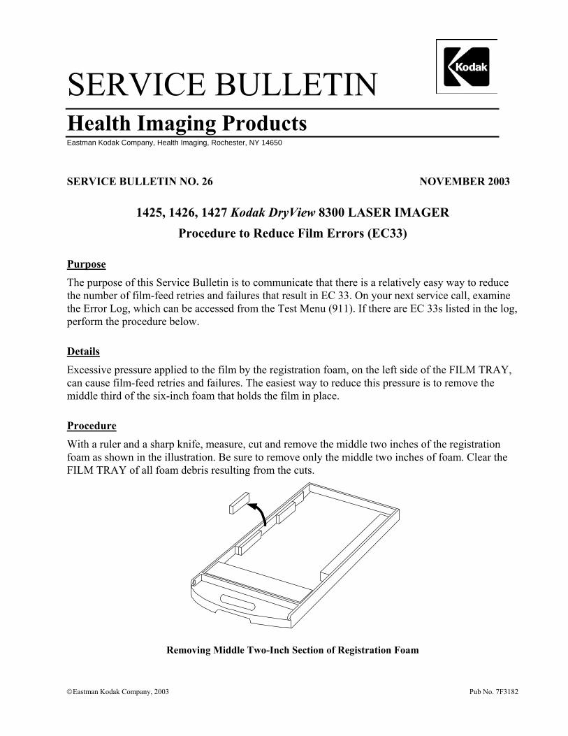
Excessive pressure applied to the film by the registration foam, on the left side of the FILM TRAY, can cause film-feed retries and failures. The easiest way to reduce this pressure is to remove the middle third of the six-inch foam that holds the film in place.
Procedure
With a ruler and a sharp knife, measure, cut and remove the middle two inches of the registration foam as shown in the illustration. Be sure to remove only the middle two inches of foam. Clear the FILM TRAY of all foam debris resulting from the cuts.
Removing Middle Two-Inch Section of Registration Foam
Eastman Kodak Company, 2003 Pub No. 7F3182

Gary J. Ketch, Service Engineer-Oakdale
For more information please contact:
Eastman Kodak Company Health Imaging 1 Imation Way Discovery Building 3B-62 Oakdale, MN 55128-3414, USA 1-800-328-2910
Kodak and DryView are trademarks.
Printed in the USA. Pub No. 7F3182 ©Eastman Kodak Company, 2003 Rochester, NY 14650
HEALTH IMAGING

SERVICE BULLETIN Health Imaging Products
Eastman Kodak Company, Health Imaging, Rochester, NY 14650
�Eastman Kodak Company, 2002 Pub No. 8E7557
SERVICE BULLETIN NO. 25 November 2002
1425, 1426 and 1427 Kodak DryView 8300 LASER IMAGER
GAS SHOCK ABSORBER May Allow TOP COVER to Close
Purpose
The purpose of this service bulletin is to communicate that if the GAS SHOCK ABSORBER becomes weak, it may allow the TOP COVER to close even if the operator does not want it to close.
Procedure
On the next service call and then during each PM call thereafter, check the operation of the GAS SHOCK ABSORBER (SP78-8100-0495-8) that is used to keep the TOP COVER open. If it fails to securely hold the TOP COVER in its full open position, replace it.

Printed in the USA. Pub No. 8E7557 ©Eastman Kodak Company, 2002 Rochester, NY 14650 HEALTH IMAGING
Gary Ketch, Service Engineer-Oakdale For more information please contact:
Eastman Kodak Company Health Imaging 1 Imation Way Discovery Building 3B-62 Oakdale, MN 55128-3414, USA 1-800-328-2910
Kodak and DryView are trademarks.
SERVICE BULLETIN Health Imaging Products
Eastman Kodak Company, Health Imaging, Rochester, NY 14650
�Eastman Kodak Company, 2002 Pub No. 8E6997
SERVICE BULLETIN NO. 24 October 2002
1425, 1426 and 1427 Kodak DryView 8300 LASER IMAGER
Scratch Reduction Tool Available
Purpose
The purpose of this service bulletin is to provide information about a new tool that can be used to reduce repetitive scratching caused by particles or nicks on the FILM GUIDE SCOOP.
Procedure
To assist in the removal of repetitive scratches caused by particles or nicks on the lower FILM GUIDE SCOOP order the CROCUS CLOTH KIT 8E2083.
The CROCUS CLOTH is inserted manually onto the SCOOP, in the same manner as a piece of film would travel on the scoop. It is then rubbed against the entire length of the SCOOP so that it reaches the top edge, near the CAPSTAN ROLLER.
Once the polishing process is complete, clean the SCOOP thoroughly with an alcohol wipe such as a TX-1065 to remove any particles that were dislodged by the CROCUS CLOTH.
Printed in the USA. Pub No. 8E6997 ©Eastman Kodak Company Rochester, NY 14650
HEALTH IMAGING
Gary Ketch, Service Engineer-Oakdale
For more information please contact:
Eastman Kodak Company Health Imaging 1 Imation Way Discovery Building 3B-62 Oakdale, MN 55128-3414, USA 1-800-328-2910
Kodak and DryView are trademarks.
SERVICE BULLETIN Health Imaging Products
Eastman Kodak Company, Health Imaging, Rochester, NY 14650
�Eastman Kodak Company, 2002 Pub No. 8E6688
SERVICE BULLETIN NO. 23 AUGUST 2002
1425, 1426 and 1427 Kodak DryView 8300 LASER IMAGER
Instructions for Grounding the PROCESSOR ASSEMBLY to Eliminate EC88s
Purpose
The purpose of this service bulletin is to provide instructions for grounding the PROCESSOR ASSEMBLY using the PROCESSOR GROUNDING HARDWARE KIT, 8E2003.
Procedure
1. Remove the SPRING CLIPS from the FRAME and CLAMSHELL of the PROCESSOR ASSEMBLY (see Fig. 1).
2. Attach one end of the WIRE (supplied in the KIT) to the STRIPPER ASSEMBLY using the right mounting SCREW of the STRIPPER ASSEMBLY (see Fig. 2).
3. Attach one end of 1 small STRAP (supplied in the KIT) along with the loose end of the WIRE referred to in Step 2, to the FRAME where the CLIP was removed in Step 1 (see Fig. 2).
4. Remove the SCREW holding the ROLLER ASSEMBLY MOUNTING ROD, and using the supplied SPACER and SCREW, attach the loose end of the small STRAP to the ROLLER ASSEMBLY MOUNTING ROD (see Fig. 2).
5. Repeat Steps 3 and 4 to attach the remaining small STRAP to either side of the CLAMSHELL portion of the PROCESSOR ASSEMBLY.

Page 2 Pub No. 8E6688
Figure 1
Figure 2
1. Remove
2. Connect WIRE to STRIPPER ASSEMBLY
3. Connect WIRE to one end of STRAP
4. Add STRAP, SPACER and SCREW to ROLLER ASSEMBLY

Pub No. 8E6688 Page 3
Gary Ketch, Service Engineer-Oakdale For more information please contact:
Eastman Kodak Company Health Imaging 1 Imation Way Discovery Building 3B-62 Oakdale, MN 55128-3414, USA 1-800-328-2910
SERVICE BULLETIN Health Imaging Products
Eastman Kodak Company, Health Imaging, Rochester, NY 14650
�Eastman Kodak Company, 2002 Pub No. 8E6674
SERVICE BULLETIN NO. 22 AUGUST 2002
1425, 1426 and 1427 Kodak DryView 8300 LASER IMAGER
Clicking Sound Coming From Left Side of IMAGER
Purpose
The purpose of this service bulletin is to communicate what causes, and how to correct the intermittent clicking sound that may be heard in the left side of the IMAGER.
Cause
The BEARINGS inside the COMPOUND PULLEY are loose causing them to move in and out. The BEARING ASSEMBLIES are supposed to be glued into the COMPOUND PULLEY so that they can’t be removed.
Solution
Replace the COMPOUND PULLEY 78-8100-0410-7. Before installing it into the IMAGER, be sure that both BEARINGS are firmly in place within the COMPOUND PULLEY.

Printed in the USA. Pub No. 8E6674 ©Eastman Kodak Company, 2002 Rochester, NY 14650 HEALTH IMAGING
Gary Ketch, Service Engineer-Oakdale For more information please contact:
Eastman Kodak Company Health Imaging 1 Imation Way Discovery Building 3B-61 Oakdale, MN 55128-3414, USA 1-800-328-2910
Kodak and DryView are trademarks.
Health Imaging
Technical Bulletin 8300
Eastman Kodak Company
1 Imation WayOakdale, MN 55128
Health Imaging Products
http://www.kodak.comPrinted in the U.S.A.
© Kodak 2000 Sept.
5-9/00 Clicking Sound from Left Side of Imager
Problem:Intermittent clicking sound from the left side of the imager.
Cause:The Compound Pulley (78-8100-0410-7), which transfers power from the main drive belt to the Separator Assembly, is made up of a black plastic pulley housing and two bearings. If one of the bearings starts to deteriorate, it will cause the pulley to emit an intermittent clicking sound.
Solution:Replace the bad bearing. The bearings are the same Common Bearing (78-8113-2008-0) used throughout the imager, and can be replaced individually. If the Pulley Mounting Shaft (78-8100-0614-4) has been damaged by the bearing, it also can be easily replaced.
6-9/00 Thumping Sound from Left Side of Imager
Problem:Occasional thumping sound from the left side of the imager.
Cause:The main drive belt, which connects the main stepper motor to the Separator Assembly and the Processor Assembly, can skip a tooth from time to time, causing the thumping sound. This skipping of teeth, which can be caused by a loose belt, results in belt wear. The belt wear is evidenced by a buildup of black “powder” (belt particles) on the left side frame and base plate. If the problem condition has existed for a long time, the black powder can build up on the teeth of the Compound (two part) Pulley. This buildup on the pulley can cause the belt to continue to skip, even after its tension has been adjusted.
Solution:Tighten the tension of the main drive belt, as necessary, by adjusting the eccentric. Check for powder buildup on the Compound Pulley, and clean the pulley, as necessary. (The Compound Pulley is black, so the powder buildup is not easy to see.)
2
7-9/00 Thin Horizontal Line Across Width of Film
Problem:A horizontal line appears across the film, about 5-1/2 inches from the top. It may look like image data is missing in one or two scan lines. The line, which may be intermittent, occurs across the entire width of the film, traversing both the image and the borders.
Cause:The operator may have removed a jam and attempted to snap the upper film guide back into place, but only one side got latched. The line is caused by the film hesitating while it is being imaged, as it enters the processor assembly.
Solution:As a phone fix, ask the operator to reseat the upper film guide and ensure that it is snapped into place on both sides.
Model 8300 Technical Bulletins
7-2/98
ATL HDI DICOM Print Setup
Currently the HDI 3000 and 5000 have DICOM print available, but the HDI 1000 does not. Use thefollowing procedures to change the DICOM print parameters on the HDI 3000 and 5000.
All options are selected by moving the cursor with the trackball to the appropriate menu item andpressing the Select key.
Network Printer Configuration Parameters
1. Press the Setups key to access the Setups Options directory.
2. Select Access Link Directory.
3. Select Configuration Files.
4. Select Edit.
5. Select Host Table.
6. Scroll to and select Image Parameters.
Model 8300 Technical Bulletins
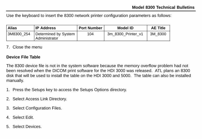
Use the keyboard to insert the 8300 network printer configuration parameters as follows:
Alias IP Address Port Number Model ID AE Title
3M8300_254 Determined by SystemAdministrator
104 3m_8300_Printer_v1 3M_8300
7. Close the menu
Device File Table
The 8300 device file is not in the system software because the memory overflow problem had notbeen resolved when the DICOM print software for the HDI 3000 was released. ATL plans an 8300disk that will be used to install the table on the HDI 3000 and 5000. The table can also be installedmanually.
1. Press the Setups key to access the Setups Options directory.
2. Select Access Link Directory.
3. Select Configuration Files.
4. Select Edit.
5. Select Devices.
Model 8300 Technical Bulletins
6. Move the cursor to the appropriate file name (such as 3M–8300.V1) and press the Select key todisplay it in the selection window.
7. Move the cursor to OK to display the device file.
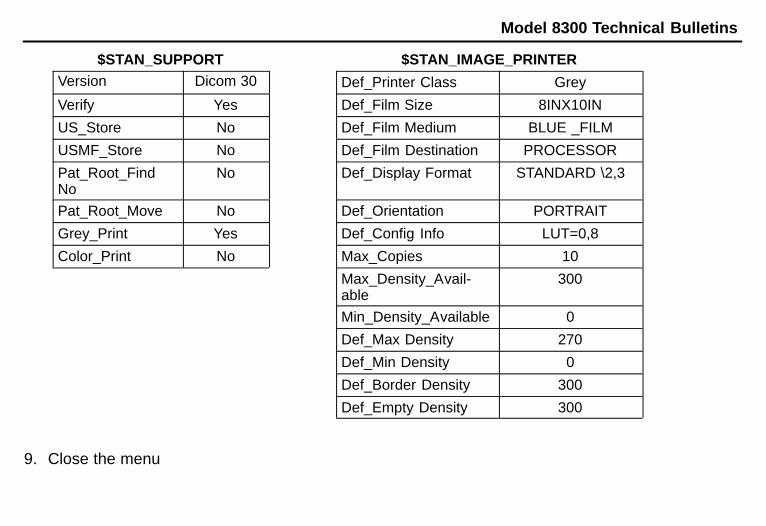
8. Scroll and edit the device file. For the 8300, the $STAN_SUPPORT and$STAN_IMAGE_PRINTER sections of the device file should be as follows:
Model 8300 Technical Bulletins
$STAN_SUPPORT $STAN_IMAGE_PRINTERVersion Dicom 30 Def_Printer Class Grey
Verify Yes Def_Film Size 8INX10IN
US_Store No Def_Film Medium BLUE _FILM
USMF_Store No Def_Film Destination PROCESSOR
Pat_Root_FindNo
No Def_Display Format STANDARD \2,3
Pat_Root_Move No Def_Orientation PORTRAIT
Grey_Print Yes Def_Config Info LUT=0,8
Color_Print No Max_Copies 10
Max_Density_Avail-able
300
Min_Density_Available 0
Def_Max Density 270
Def_Min Density 0
Def_Border Density 300
Def_Empty Density 300
9. Close the menu
Model 8300 Technical Bulletins
Operator accessible printer parameters
The clinical operators of the HDI 3000 will not access the above tables. They can select format,orientation, maximum and minimum density, and number of copies within the operator’s B&W printermenu. The HDI 3000 will be installed with the LUT set for the customer by ATL marketing personnel,not to be changed unless the customer wants a different look for the films.
Imation Enterprises Corp.1 Imation PlaceOakdale, MN 55128�3414888 466 3456 phone888 704 7100 faxhttp://www.imation.com
Printed in the U.S.A.
Imation 1998 December
Technical Bulletin 12/28/98
DryView LaserImagerModel 8300
TM
25�12/98 Cart Commercially Available
Rubbermaid makes a flat shelf cart that can support up to 200 lbs. and is big enough for the 8300.The model number is 4505 and costs approximately $120. Thanks to John Bennie for supplyingthis tip.
26�12/98 Remote Acquire Unit Available From SPC
Some ultrasound customers want the 8300 to be able to acquire images by pressing the Print orExpose keys on their ultrasound consoles instead of using the 8300's remote keypad. There is nowan interface device available that connects between the 8300, its remote keypad and the ultrasoundunit which will trigger the 8300 to acquire when the signal is received from the ultrasound. The kit(interface box and cable) is available through sales with part number 78�8114�2797�6 and has a listprice of $195.
Kodak Health Imaging1 Imation PlaceDiscovery 4B-74Oakdale, MN 55125Tel. (651) 704-4000http://www.kodak.com
Printed in the U.S.A. Kodak 1999 July
Technical Bulletin 07/30/99
DryView Laser ImagerModel 8300
3-6/99 Film Count (Exposures) Meter ReadingThere are two quick ways to check the film count on the 8300. First, press either Setup button,followed by 999 and Enter. Then arrow down to item 10. Exposures . The film count labelledExposures will be displayed. Press Exit to return the 8300 to the Ready condition. A second andquicker way is to press Test, followed by 911 and Enter. The first menu item displayed is 1. ExamineSystem Error Log . Press Enter and the first log entry will display the film count labelled asExposures. Press Exit twice to return the 8300 to the Ready condition.

Health Imaging
Technical Bulletin 8300
Eastman Kodak Company
1 Imation WayOakdale, MN 55128
Health Imaging Products
http://www.kodak.comPrinted in the U.S.A.
© Kodak 2000 Dec.
8-11/00 POEIB No longer AvailableThe POEIB was originally designed as an interface to allow the DryView 8300 to be connected to and print from an 8800. There is a highly intermittent software bug in the 8800 that causes the system to hang up. Because of the age of this equipment, and because the PACS Link 9410 Acquisition System is a viable substitute, the POEIB is no longer available for sale, and no new installations of this equipment are to be made.

2
Blank Page
Health Imaging
Technical Bulletin DryView 8300
Eastman Kodak Company
1 Imation WayOakdale, MN 55128
Health Imaging Products
http://www.kodak.comPrinted in the U.S.A.© Kodak 2001 Jan.
9-01/01 DryView Film Numbering Code Change
There will be a slight change in what the Lumonics system will print on the edge of all sheets of DryView film. The letter that designates whether the product is DVB, DVC, or DVM has been eliminated. Following is an example of what used to be printed on the film:
KODAK DRYVIEW M EXP 03/01 D2231-01-B 03 2945
Where: KODAK = Company nameDRYVIEW = ProductM = Subproduct: either M (Mammo), B (Blue), or C (Clear)EXP 03/01 = Expiration dateD = Plant code for White City2231 = Lot number-01 = Jumbo number-B = Band within jumbo03 = Sheeter number2945 = Sheet number within band
This is how the new printing will look:
KODAK DRYVIEW EXP 03/01 D2231-01-B 03 2945
Note that all items are the same as in the earlier format except the letter designation between DRYVIEW and the expiration date has been eliminated.
Health Imaging
Technical Bulletin DryView 8300
Eastman Kodak Company
1 Imation WayOakdale, MN 55128
Health Imaging Products
http://www.kodak.comPrinted in the U.S.A.© Kodak 2001 Feb.
10-02/01 EC27 - Film Stopping in Processor
ProblemFilm takes too long to pass through the processor, and the software times out, producing an Error Code 27.
CauseFilm did not get a positive start into the processor. There are several possible causes of this:
1. Bowed entrance guides caused by over-tightening of the mounting hardware during production. The bow produces a high resistance in the film path. (See solution 1 below.)
2. Metal entrance roller is slipping on its shaft. (See Solution 2 below.)
3. Rubber entrance pinch roller has become glazed or hardened and is no longer grabbing the leading edge of the film.
Solution1. Remove the processor assembly and loosen the screws and/or nuts that secure the entrance guides
(located on the under side). Confirm that the guides are no longer bowed. Then tighten the hardware only enough to keep the guides from moving.
2. Remove the metal entrance roller and confirm that the drive side shaft is securely attached to the roller. If it is not, remove the shaft, put a small drop of epoxy in the roller and slowly press the shaft back into the roller. If you are unsuccessful in securing the shaft, replace the roller (78-8100-0293-7).
3. Clean the rubber roller with alcohol. If the surface does not appear to be soft and supple after cleaning, replace the roller (78-8113-2104-7).

2
This page is intentionally left blank.
Service & SupportHealth Imaging
Kodak DryView 8300 LASER IMAGERS
Technical Bulletin August 2001
Eastman Kodak Company
1 Imation WayOakdale, MN 55128
Health Imaging Products
http://www.kodak.comPrinted in the U.S.A.
© Kodak 2001 August
11-08/01 EC27 or EC28 - Film Stopping in Processor (Reissue)
This Technical Bulletin is a revision and reissue of Technical Bulletin 14-04/01, EC27 - Film Stopping in Processor.
ProblemFilm moves through the PROCESSOR too slowly and the software times out, producing an Error Code 27 or Error Code 28.
CauseFilm did not start correctly into the PROCESSOR. There are several possible causes, in addition to CPU PWA resistors R36 and R39 (see Technical Bulletin 21-11/98):
1. Bowed ENTRANCE GUIDES caused by over-tightening the MOUNTING HARDWARE. The bow produces a high resistance in the film path. (See Solution 1.)
2. Metal ENTRANCE or EXIT ROLLER has broken loose from their SHAFT. (See Solution 2.)
3. Rubber ENTRANCE and EXIT PINCH ROLLERS are coated or hardened and cannot capture the leading edge of the film. (See Solution 3.)
4. The ends of the SHAFT of the rubber ENTRANCE and EXIT PINCH ROLLERS are contaminated and do not rotate freely in their BUSHINGS.
Solution1. Remove the PROCESSOR ASSEMBLY and loosen the SCREWS and/or NUTS that secure the
ENTRANCE GUIDES (located on the underside). Check that the GUIDES are not bowed., then tighten the HARDWARE only enough to keep the GUIDES from bowing.
2. Remove the metal ENTRANCE or EXIT ROLLERS and check that each DRIVE SIDE SHAFT is correctly installed on the ROLLER. If it is not, remove the SHAFT, put a small drop of epoxy in the ROLLER and slowly press the SHAFT back into the ROLLER. If you cannot install the SHAFT, replace the ENTRANCE ROLLER (78-8100-0293-7) or EXIT ROLLER (78-8100-0431-3), as needed.
3. Clean both rubber ROLLERS with alcohol. If the surface is not soft and supple after cleaning, replace the ROLLER (78-8113-2104-7).
4. Remove the ROLLERS from their BUSHINGS in the PROCESSOR and clean the ends of the SHAFTS with a SCOURING PAD or STEEL WOOL until they are smooth. Clean the insides of the BUSHINGS to remove any contamination. Check that the BUSHINGS rotate freely on the ends of the SHAFTS before installing in the PROCESSOR ASSEMBLY. If the BUSHINGS are scored or still do not rotate freely, install new BUSHINGS (8E2021, set of 2).
Service & SupportHealth Imaging
Kodak DryView 8300 LASER IMAGERS
Technical Bulletin October 2001
Eastman Kodak Company
1 Imation WayOakdale, MN 55128
Health Imaging Products
http://www.kodak.comPrinted in the U.S.A.
© Kodak 2001
13-10/01 Disable Debug after a Service Call
If you use the Debug software (Control+D) during a service call to monitor IMAGER operations such as calibrating or transporting a film or the temperature of the DRUM, you must disable it before leaving the account.
If Debug is not disabled, it could cause film calibration to take several minutes longer than normal. Failure to disable Debug might also cause the IMAGER to beep when there is a small deviation in temperature readings from the DRUM.
If your COMPUTER is connected to the IMAGER, type [Control+D] to disable Debug. If your COMPUTER has been disconnected and you don’t know if Debug is still active, energize and then de-energize the IMAGER to disable Debug.

Printed in U.S.A. • 13-10-01_disableDebug.fm
EASTMAN KODAK COMPANYRochester, NY 14650 HEALTH IMAGING
DryView and Kodak are trademarks.
Service & SupportHealth Imaging
Kodak DryView 8300 LASER IMAGERS
Technical Bulletin January 2002
Eastman Kodak Company
1 Imation WayOakdale, MN 55128
Health Imaging Products
http://www.kodak.comPrinted in the U.S.A.
© Kodak 2002
14-01/02 Light Density Streaks on Film - Reissue
ProblemLight streaks appear down the film, usually around the middle, and most are visible in the mid-tone grays of the images.
CauseDust has collected on the final MIRROR that directs the laser beam to the film.
Solution1. Make a print of a calibration sheet. A calibration sheet might show the artifact.
2. Remove the OPTICS MODULE from the imager and set it on a TABLE in the same position as when it is in the imager.
3. Using the OPTICS MODULE CLEANING KIT 74-0401-8238-3, insert the NOZZLE from the CANISTER into the laser-beam aperture slot of the OPTICS MODULE.
4. Holding the CANISTER upright, spray short bursts while moving the NOZZLE back and forth along the aperture slot.
NoteDo not touch the MIRROR with the NOZZLE and do not tilt, invert or shake the CANISTER while spraying air into the opening.
5. Remove the NOZZLE and install the OPTICS MODULE in the imager.
6. Make another print of a calibration sheet.
7. Compare the print with the calibration sheet from Step 1 to check that the light streak has been removed.
Service & SupportHealth Imaging
Kodak DryView 8300 LASER IMAGERS
Technical Bulletin October 2001
Eastman Kodak Company
1 Imation WayOakdale, MN 55128
Health Imaging Products
http://www.kodak.comPrinted in the U.S.A.
© Kodak 2001
15-10/01 Cost Savings for Replacing PRESSURE ROLLERS
If the UPPER PRESSURE ROLLERS in the PROCESSOR stop turning, the ROLLERS can deplate or flatten. If this occurs, the DRUM will be covered with aluminum deposits and change to a black color. If you have a problem with the UPPER PRESSURE ROLLERS, installing only the ROLLER ASSEMBLY in place of installing a new PROCESSOR ASSEMBLY will result in a cost savings for Kodak.
To correct this problem, install a new ROLLER ASSEMBLY(S) and clean the DRUM. This will result in the following cost savings:
• Installing 9 ROLLER ASSEMBLY (cover) and 3 ROLLER ASSEMBLY (base): savings = $2506.00.
• Installing 9 ROLLER ASSEMBLY (cover), 3 ROLLER ASSEMBLY (cover), and the DRUM: savings = $1651.00.
Service & SupportHealth Imaging
Kodak DryView 8300 LASER IMAGERS
Technical Bulletin December 2001
Eastman Kodak Company
1 Imation WayOakdale, MN 55128
Health Imaging Products
http://www.kodak.comPrinted in the U.S.A.
© Kodak 2001
16-12/01 Light-Weight FILM FEED ROLLERS
All new Kodak DryView 8300 LASER IMAGERS are being sent with the same light-weight FILM FEED ROLLER that has been used in the Kodak DryView 8600 and 8610 LASER IMAGERS. With the light-weight FILM FEED ROLLER, there will be a reduction in the number of scratches caused when a sheet of film feeds from the FILM TRAY.
The new light-weight FILM FEED ROLLER 6E8549, which is stocked in Service Parts, includes 4 nylon SPACERS to install in place of the old ROLLER.
ImportantWhen the new ROLLER is installed, the FILM TRAY might not eject to its full normal position.
After installing the light-weight FILM FEED ROLLER, do the following:
1. Locate the TRAY POSITIONING GUIDE on the left side of the FILM TRAY slot.
2. Remove:
• 2 spring-loaded PADS
• SPRINGS
3. Install the TRAY POSITIONING GUIDE again.
If the new FILM FEED ROLLER cannot feed the last sheets of film in the FILM TRAY, the FILM TRAY might have to be replaced with a FILM TRAY with lighter-density foam. All of the FILM TRAYS stocked in Service Parts have FOAM with a lighter density. The new FILM TRAYS can be identified by the ½-in. Kodak logo on the outside bottom of the TRAY.
Printed in U.S.A. • 16_17-12-01_FilmTray_FilmFeed.fm
EASTMAN KODAK COMPANYRochester, NY 14650 HEALTH IMAGING
17-12/01 FILM TRAY will not feed Film
Problem
Continual EC 33 error codes occur, or the new light-weight FILM FEED ROLLER cannot feed the last sheets of film in the FILM TRAY.
Cause
When the film is at a low level, the density of the FOAM used for registration in the FILM TRAY causes pressure on the film.
Solution
Replace the FILM TRAY 78-8096-3201-7. All of the FILM TRAYS stocked in Service Parts have FOAM with a lighter density. The new FILM TRAYS can be identified by the ½-in. Kodak logo on the outside bottom of the TRAY.
Kodak and DryView are trademarks.
Service & SupportHealth Imaging
Kodak DryView 8300 LASER IMAGERS
Technical Bulletin January 2002
Eastman Kodak Company
1 Imation WayOakdale, MN 55128
Health Imaging Products
http://www.kodak.comPrinted in the U.S.A.
© Kodak 2002
18-01/02 FILM TRAY will not Unlock - Reissue
Problem
The FILM TRAY will not unlock and cannot be pulled out because the FILM TRAY DETECTION PIN is caught on the side of the FILM TRAY.
Cause
The TOP COVER RELEASE BUTTON is partially engaged because it is pressed against the RIGHT SIDE PANEL. This binds up the LOCKING MECHANISM so it cannot move freely and release the FILM TRAY.
Solution
Install a new COVER RELEASE BUTTON ASSEMBLY 78-8113-2013-0 that includes a smaller RELEASE BUTTON.
Service & SupportHealth Imaging
Kodak DryView 8300 LASER IMAGERS
Technical Bulletin January 2002
Eastman Kodak Company
1 Imation WayOakdale, MN 55128
Health Imaging Products
http://www.kodak.comPrinted in the U.S.A.
© Kodak 2002
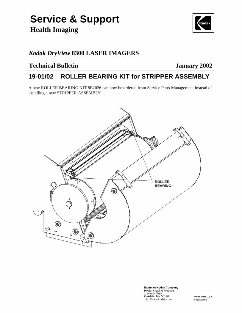
19-01/02 ROLLER BEARING KIT for STRIPPER ASSEMBLY
A new ROLLER BEARING KIT 8E2026 can now be ordered from Service Parts Management instead of installing a new STRIPPER ASSEMBLY.
ROLLERBEARING
Service & SupportHealth Imaging
Kodak DryView 8300 LASER IMAGER SYSTEM
Technical Bulletin April 2002
Eastman Kodak Company
1 Imation WayOakdale, MN 55128
Health Imaging Products
http://www.kodak.comPrinted in the U.S.A.© Kodak 2002
20-04/02 Version 4.9 Firmware Contrast IssueChanges made in the firmware for V 4.9 cause films from the Kodak DirectView CR 800 SYSTEM to be light and might cause contrast problems for other MODALITIES.
The 2 changes are:
• MODALITY group numbering was changed from the range 0 – 10 to the range 1 – 11 (numbering change only).
• The internal handling of the contrast in the host control DZO of the 8300 LASER IMAGER. Command was changed to ignore the default setting on the LOCAL PANEL but increases the selection from 1 to 264.
These changes will be corrected and released on the firmware for the 8300 LASER IMAGER (effective with V4.9.1) as soon as possible. Until then:
1. The “Modality Groups” on the “8300 Service Installation” menu are now numbered from 1 to 11. If you select group number 2 before installing V 4.9 firmware, you should select group number 3 after installation. Version 4.9 firmware contains a feature that automatically changes the default from 2 to 3. Check this after completing the installation.
2. The internal DZO handling will only impact performance with the Kodak PACS LINK 9410 ACQUISITION SYSTEM, Kodak PACS LINK MEDICAL IMAGER MANAGERS 100/200/50, Kodak PACS LINK 25 PRINT SERVER and Kodak PACS LINK DICOM PRINT SERVERS, or HOST CONTROL INTERFACES for OEMs that control the SERIAL INTERFACE on the 8300 LASER IMAGER.
To prevent any grayscale or contrast problems caused by selecting incorrect contrast tables, you should install V 4.6 firmware instead of V4.9 firmware.

SERVICE BULLETIN Health Imaging Products
Eastman Kodak Company, Health Imaging, Rochester, NY 14650
�Eastman Kodak Company, 2002 Pub No. 8E6644
SERVICE BULLETIN NO. 21 AUGUST 2002
1425, 1426 and 1427 Kodak DryView 8300 LASER IMAGER
EC27 or EC28 – Film Stopping in PROCESSOR
Purpose
The purpose of this service bulletin is to communicate how to correct a problem that is caused when the film moves too slowly through the PROCESSOR.
Problem
The film moves through the PROCESSOR too slowly and the system software times out, producing an Error Code 27 or Error Code 28.
Cause
The film did not start correctly into the PROCESSOR because the metal entrance DRIVE ROLLER is too smooth and does not positively “grab” the film.
Solution
Remove the metal entrance DRIVE ROLLER from the PROCESSOR assembly. Hold the ROLLER firmly in one hand, and wrap a piece of 7447 (very fine) 3M Scotch-Brite PAD (TL5635) partially around the ROLLER with the other hand. While turning, pushing and pulling the ROLLER with one hand, hold the PAD against the ROLLER and turn and twist with the other hand. The expected result is that the PAD will create a very subtle dull, cross-hatched pattern on the ROLLER that will make it rough enough to properly grab the film. As an alternative, a factory rough DRIVE ROLLER (8E2075) is available from Service Parts.
When replacing the ROLLER into the PROCESSOR, be sure to position the SPACER WASHERS so that their smooth edge faces the BUSHINGS that hold the ROLLER in position.
After replacing the ROLLER if there is still a problem with film stopping in the PROCESSOR, refer to Technical Bulletin 11-08/01.

Printed in the USA. Pub No. 8E6644 ©Eastman Kodak Company, 2002 Rochester, NY 14650 HEALTH IMAGING
Gary Ketch, Service Engineer-Oakdale For more information please contact:
Eastman Kodak Company Health Imaging 1 Imation Way Discovery Building 3B-61 Oakdale, MN 55128-3414, USA 1-800-328-2910
Kodak and DryView are trademarks.
Kodak Health Imaging1 Imation PlaceDiscovery 4B-74Oakdale, MN 55125Tel. (651) 704-4000http://www.kodak.com
Printed in the U.S.A. Kodak 1999 October
Technical Bulletin 10/15/99
DryView Laser ImagingSystem / for Mammography8600
1-10/99 8600 Training BulletinThis training document is for Field Engineers (FEs) who have been trained on the 8300 and have hadsome hands-on experience with that system. In addition, the FEs must have been trained on thePACS Link 9410 Acquisition System. The information supplied in this bulletin is specific to theinstallation and operation of the Kodak DryView 8600 Laser Imaging System / for Mammography. Formore detailed information on the 9410, please see the PACS Link 9410 Acquisition System ServiceManual.
NoteThe following information is organized in the section by section format of the 8300 and 8600Service Manual.
1. Specifications
1-1. Dimensions
Height: 46 cm (18 in.)Width: 46 cm (18 in.)Depth: 66 cm (26 in.)Weight 56 Kg (124 lb.)
1-2. Electrical
Phase: SingleVoltage: 100-240 VAC ± 10%
50 – 60 Hz ± 3 HzPower: 450 WattsCurrent: 6.3/3.2 Amperes
1-3. Operating Environment
Temperature: 15 to 32°C (59 to 90°F)Relative Humidity: 15% to 75% RH, NoncondensingMagnetic Field: <= 100 GaussHeat Production: 700 BTU, typicalAcoustic Noise: <55dB standby; <60 dB transient
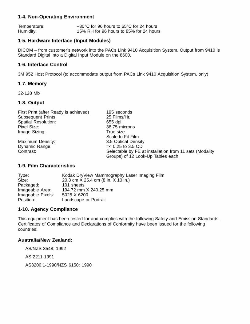
1-4. Non-Operating Environment
Temperature: –30°C for 96 hours to 65°C for 24 hoursHumidity: 15% RH for 96 hours to 85% for 24 hours
1-5. Hardware Interface (Input Modules)
DICOM – from customer’s network into the PACs Link 9410 Acquisition System. Output from 9410 isStandard Digital into a Digital Input Module on the 8600.
1-6. Interface Control
3M 952 Host Protocol (to accommodate output from PACs Link 9410 Acquisition System, only)
1-7. Memory
32-128 Mb
1-8. Output
First Print (after Ready is achieved) 195 secondsSubsequent Prints: 25 Films/Hr.Spatial Resolution: 655 dpiPixel Size: 38.75 micronsImage Sizing: True size
Scale to Fit FilmMaximum Density: 3.5 Optical DensityDynamic Range: =< 0.25 to 3.5 ODContrast: Selectable by FE at installation from 11 sets (Modality
Groups) of 12 Look-Up Tables each
1-9. Film Characteristics
Type: Kodak DryView Mammography Laser Imaging FilmSize: 20.3 cm X 25.4 cm (8 in. X 10 in.)Packaged: 101 sheetsImageable Area: 194.72 mm X 240.25 mmImageable Pixels: 5025 X 6200Position: Landscape or Portrait
1-10. Agency Compliance
This equipment has been tested for and complies with the following Safety and Emission Standards.Certificates of Compliance and Declarations of Conformity have been issued for the followingcountries:
Australia/New Zealand:
AS/NZS 3548: 1992
AS 2211-1991
AS3200.1-1990/NZS 6150: 1990
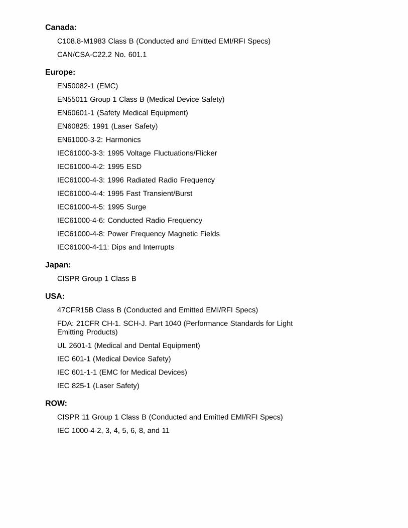
Canada:
C108.8-M1983 Class B (Conducted and Emitted EMI/RFI Specs)
CAN/CSA-C22.2 No. 601.1
Europe:
EN50082-1 (EMC)
EN55011 Group 1 Class B (Medical Device Safety)
EN60601-1 (Safety Medical Equipment)
EN60825: 1991 (Laser Safety)
EN61000-3-2: Harmonics
IEC61000-3-3: 1995 Voltage Fluctuations/Flicker
IEC61000-4-2: 1995 ESD
IEC61000-4-3: 1996 Radiated Radio Frequency
IEC61000-4-4: 1995 Fast Transient/Burst
IEC61000-4-5: 1995 Surge
IEC61000-4-6: Conducted Radio Frequency
IEC61000-4-8: Power Frequency Magnetic Fields
IEC61000-4-11: Dips and Interrupts
Japan:
CISPR Group 1 Class B
USA:
47CFR15B Class B (Conducted and Emitted EMI/RFI Specs)
FDA: 21CFR CH-1. SCH-J. Part 1040 (Performance Standards for Light Emitting Products)
UL 2601-1 (Medical and Dental Equipment)
IEC 601-1 (Medical Device Safety)
IEC 601-1-1 (EMC for Medical Devices)
IEC 825-1 (Laser Safety)
ROW:
CISPR 11 Group 1 Class B (Conducted and Emitted EMI/RFI Specs)
IEC 1000-4-2, 3, 4, 5, 6, 8, and 11

CE Marking:
This equipment is part of a medical system and conforms to the medical safety and EMC inEN60601-1-1, EN60601-1-2, and the 93/42/EEC, MDD (Medical Device Directive).
A Technical File and Declaration of Conformity with the Essential Requirements of the Medical DeviceDirective have been prepared and signed by the appropriate personnel and are located at:
Kodak AGQuality Services and Product Safety70323 Stuttgart GermanyTelephone 49-0711-40-06-5291
FCC:
This device complies with the limits for a Class B digital device listed in Part 15 of the FCC Rules.Operation is subject to the following two conditions:
(1) This device may not cause harmful interference, and
(2) This device must accept any interference received, including interference that may causeundesired operation.
Industry Canada:
This Class B digital apparatus meets all requirements of the Canadian Interference-CausingEquipment Regulations.
Cet appareil numérique de la Classe B respecte toutes les exigences du Règlement sur le matérialbrouilleur du Canada.
EU:
This equipment complies with the January 1996 EU Community EMC Requirements, per EN55011Class B.
2. Installation
2-1. General
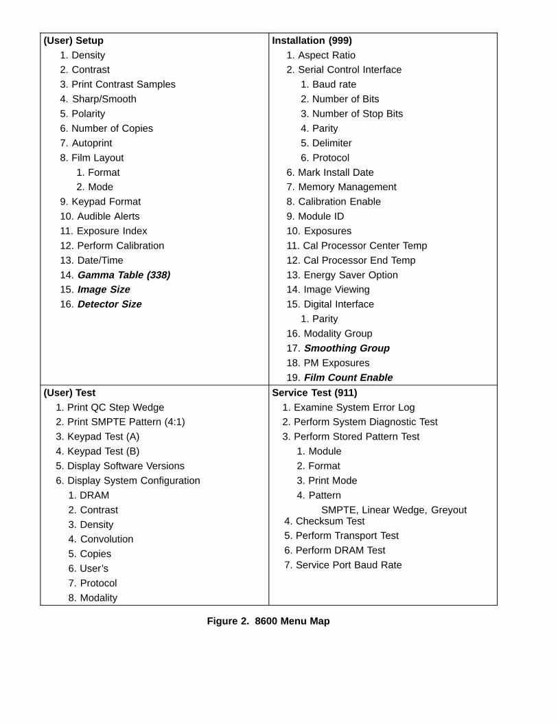
The 8600 is sold as the preferred printing choice for many Full Field Digital Mammography (FFDM)OEMs. Currently, the big players in this market are GE, Lorad (Trex) and Fischer. While the basichardware installation is the same for all FFDM modalities, the image quality parameters establishedduring OEM qualifications may be different. The basic hardware installation (see Figure 1) consists ofa 9410 Print Server that is connected to the customer’s network and receives FFDM DICOM images.The 9410 then converts the images using 952 host protocol and sends them via a COPCIL board tothe 8600 digital input module.
The reason that the 9410 is being used as a print server between the modality and the 8600, is toensure maximum throughput. The Network Input Module used in the 8300 will work in the 8600.However, the DICOM data transfer rate of the 8300 Network Input Module is too slow to handle thevery large FFDM images, which can be as large as 30 Mb. The typical ultrasound image is only1/4 Mb, so the transfer rate is not an issue when using the 8300 Network Input Module in thatapplication. Because the 8600 printing speed is greatly reduced from that of the 8300 (see paragraph1-8, Output), the data transfer rate needs to be optimum.
! CautionAs noted in the Agency Compliance paragraph above, the leakage current rating of the 8600meets the requirements for medical equipment. However the PACS Link 9410 only meetsleakage current ratings for a PC, so it must be installed no closer that 1.8 meters from a patientbed or chair, as stated in the PACS Link 9410 User Guide.
In addition, when preparing to install the system, please be aware of the following statement:
! CautionDo not use in the presence of flammable anesthetics, oxygen or nitrous oxide. Thisequipment does not have a gas sealed electronics enclosure and could ignite anyflammable or explosive gases present in its environment.
Figure 1. System Hardware Configuration
2-2. Installing the 8600
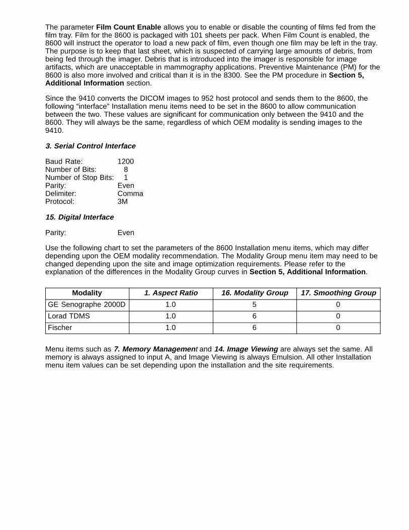
The 8600 hardware is installed the same way that an 8300 is, except that the 8600 is shipped only inone configuration: with a Digital Input Module. The input module should be in slot A, even though thelocal panel has Setup A and Setup B buttons. You may need to advise the customer that only SetupA is used. As in the 8300, the necessary Installation menu items should be configured before the“customer accessible” Setup menus items are defined. The parameters listed in both the installationand user setup menus are shown in the menu map in Figure 2.
2-2-1. Installation Menu
Two installation menu items are new to the 8600: 17. Smoothing Group and 19. Film CountEnable . The Smoothing Group will allow you to select, in the future, from 11 different (0-10)interpolation groups that will be applied in the Sharp/Smooth setting. Group 0 is the same group thathas always been used in the 8300, and is currently the recommended value for the 8600.
(User) Setup1. Density2. Contrast
3. Print Contrast Samples
4. Sharp/Smooth
5. Polarity
6. Number of Copies
7. Autoprint
8. Film Layout
1. Format2. Mode
9. Keypad Format
10. Audible Alerts
11. Exposure Index
12. Perform Calibration
13. Date/Time
14. Gamma Table (338)15. Image Size16. Detector Size
Installation (999)1. Aspect Ratio2. Serial Control Interface
1. Baud rate
2. Number of Bits
3. Number of Stop Bits
4. Parity
5. Delimiter
6. Protocol
6. Mark Install Date7. Memory Management
8. Calibration Enable
9. Module ID
10. Exposures
11. Cal Processor Center Temp
12. Cal Processor End Temp
13. Energy Saver Option14. Image Viewing
15. Digital Interface
1. Parity
16. Modality Group
17. Smoothing Group18. PM Exposures
19. Film Count Enable(User) Test
1. Print QC Step Wedge2. Print SMPTE Pattern (4:1)
3. Keypad Test (A)
4. Keypad Test (B)
5. Display Software Versions
6. Display System Configuration
1. DRAM
2. Contrast
3. Density4. Convolution
5. Copies
6. User’s
7. Protocol
8. Modality
Service Test (911)1. Examine System Error Log2. Perform System Diagnostic Test
3. Perform Stored Pattern Test
1. Module
2. Format
3. Print Mode
4. Pattern
SMPTE, Linear Wedge, Greyout4. Checksum Test5. Perform Transport Test
6. Perform DRAM Test
7. Service Port Baud Rate
Figure 2. 8600 Menu Map
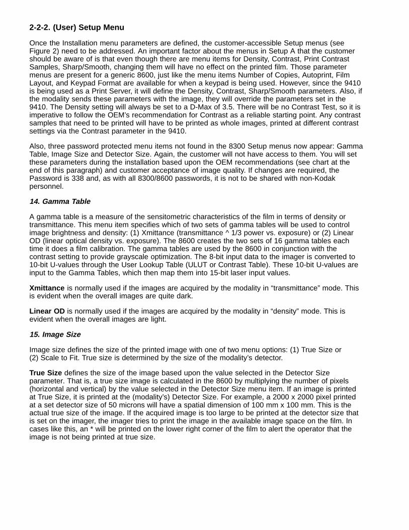
The parameter Film Count Enable allows you to enable or disable the counting of films fed from thefilm tray. Film for the 8600 is packaged with 101 sheets per pack. When Film Count is enabled, the8600 will instruct the operator to load a new pack of film, even though one film may be left in the tray.The purpose is to keep that last sheet, which is suspected of carrying large amounts of debris, frombeing fed through the imager. Debris that is introduced into the imager is responsible for imageartifacts, which are unacceptable in mammography applications. Preventive Maintenance (PM) for the8600 is also more involved and critical than it is in the 8300. See the PM procedure in Section 5,Additional Information section.
Since the 9410 converts the DICOM images to 952 host protocol and sends them to the 8600, thefollowing “interface” Installation menu items need to be set in the 8600 to allow communicationbetween the two. These values are significant for communication only between the 9410 and the8600. They will always be the same, regardless of which OEM modality is sending images to the9410.
3. Serial Control Interface
Baud Rate: 1200Number of Bits: 8Number of Stop Bits: 1Parity: EvenDelimiter: CommaProtocol: 3M
15. Digital Interface
Parity: Even
Use the following chart to set the parameters of the 8600 Installation menu items, which may differdepending upon the OEM modality recommendation. The Modality Group menu item may need to bechanged depending upon the site and image optimization requirements. Please refer to theexplanation of the differences in the Modality Group curves in Section 5, Additional Information .
Modality 1. Aspect Ratio 16. Modality Group 17. Smoothing Group
GE Senographe 2000D 1.0 5 0
Lorad TDMS 1.0 6 0
Fischer 1.0 6 0
Menu items such as 7. Memory Managemen t and 14. Image Viewing are always set the same. Allmemory is always assigned to input A, and Image Viewing is always Emulsion. All other Installationmenu item values can be set depending upon the installation and the site requirements.
2-2-2. (User) Setup Menu
Once the Installation menu parameters are defined, the customer-accessible Setup menus (seeFigure 2) need to be addressed. An important factor about the menus in Setup A that the customershould be aware of is that even though there are menu items for Density, Contrast, Print ContrastSamples, Sharp/Smooth, changing them will have no effect on the printed film. Those parametermenus are present for a generic 8600, just like the menu items Number of Copies, Autoprint, FilmLayout, and Keypad Format are available for when a keypad is being used. However, since the 9410is being used as a Print Server, it will define the Density, Contrast, Sharp/Smooth parameters. Also, ifthe modality sends these parameters with the image, they will override the parameters set in the9410. The Density setting will always be set to a D-Max of 3.5. There will be no Contrast Test, so it isimperative to follow the OEM’s recommendation for Contrast as a reliable starting point. Any contrastsamples that need to be printed will have to be printed as whole images, printed at different contrastsettings via the Contrast parameter in the 9410.
Also, three password protected menu items not found in the 8300 Setup menus now appear: GammaTable, Image Size and Detector Size. Again, the customer will not have access to them. You will setthese parameters during the installation based upon the OEM recommendations (see chart at theend of this paragraph) and customer acceptance of image quality. If changes are required, thePassword is 338 and, as with all 8300/8600 passwords, it is not to be shared with non-Kodakpersonnel.
14. Gamma Table
A gamma table is a measure of the sensitometric characteristics of the film in terms of density ortransmittance. This menu item specifies which of two sets of gamma tables will be used to controlimage brightness and density: (1) Xmittance (transmittance ^ 1/3 power vs. exposure) or (2) LinearOD (linear optical density vs. exposure). The 8600 creates the two sets of 16 gamma tables eachtime it does a film calibration. The gamma tables are used by the 8600 in conjunction with thecontrast setting to provide grayscale optimization. The 8-bit input data to the imager is converted to10-bit U-values through the User Lookup Table (ULUT or Contrast Table). These 10-bit U-values areinput to the Gamma Tables, which then map them into 15-bit laser input values.
Xmittance is normally used if the images are acquired by the modality in “transmittance” mode. Thisis evident when the overall images are quite dark.
Linear OD is normally used if the images are acquired by the modality in “density” mode. This isevident when the overall images are light.
15. Image Size
Image size defines the size of the printed image with one of two menu options: (1) True Size or(2) Scale to Fit. True size is determined by the size of the modality’s detector.
True Size defines the size of the image based upon the value selected in the Detector Sizeparameter. That is, a true size image is calculated in the 8600 by multiplying the number of pixels(horizontal and vertical) by the value selected in the Detector Size menu item. If an image is printedat True Size, it is printed at the (modality’s) Detector Size. For example, a 2000 x 2000 pixel printedat a set detector size of 50 microns will have a spatial dimension of 100 mm x 100 mm. This is theactual true size of the image. If the acquired image is too large to be printed at the detector size thatis set on the imager, the imager tries to print the image in the available image space on the film. Incases like this, an * will be printed on the lower right corner of the film to alert the operator that theimage is not being printed at true size.
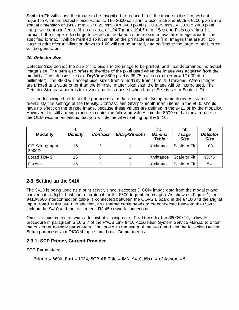
Scale to Fit will cause the image to be magnified or reduced to fit the image to the film, withoutregard to what the Detector Size value is. The 8600 can print a pixel matrix of 5025 x 6200 pixels in aspatial dimension of 194.7 mm x 240.25 mm. (An 8600 pixel is 0.03875 mm.) A 2000 x 2000 pixelimage will be magnified to fill up an area of 194.7 mm x 194.7 mm if Scale to Fit is used in a 1:1format. If the image is too large to be accommodated in the maximum available image area for thespecified format, it will be minified so it can fit on the printable area of film. Images that are still toolarge to print after minification down to 1.00 will not be printed, and an “image too large to print” errorwill be generated.
16. Detector Size
Detector Size defines the size of the pixels in the image to be printed, and thus determines the actualimage size. The term also refers to the size of the pixel used when the image was acquired from themodality. The intrinsic size of a DryView 8600 pixel is 38.75 microns (a micron = 1/1000 of amillimeter). The 8600 will accept pixel sizes from a modality from 10 to 250 microns. When imagesare printed at a value other than the intrinsic imager pixel size, the image will be interpolated. TheDetector Size parameter is irrelevant and thus unused when Image Size is set to Scale to Fit.
Use the following chart to set the parameters for the appropriate Setup menu items. As statedpreviously, the settings of the Density, Contrast, and Sharp/Smooth menu items in the 8600 shouldhave no effect on the printed image, because these values are defined in the 9410 or by the modality.However, it is still a good practice to enter the following values into the 8600 so that they equate tothe OEM recommendations that you will define when setting up the 9410.
Modality1.
Density2.
Contrast4.
Sharp/Smooth14.
GammaTable
15.ImageSize
16.Detector
Size
GE Senographe2000D
16 3 1 Xmittance Scale to Fit 100
Lorad TDMS 16 6 1 Xmittance Scale to Fit 38.75
Fischer 16 3 1 Xmittance Scale to Fit 54
2-3. Setting up the 9410
The 9410 is being used as a print server, since it accepts DICOM image data from the modality andconverts it to digital host control protocol for the 8600 to print the images. As shown in Figure 1, the9410/8600 interconnection cable is connected between the COPSIL board in the 9410 and the DigitalInput Board in the 8600. In addition, an Ethernet cable needs to be connected between the RJ-45jack on the 9410 and the customer’s RJ-45 network connection.
Once the customer’s network administrator assigns an IP address for the 8600/9410, follow theprocedure in paragraph 3-10-3-7 of the PACS Link 9410 Acquisition System Service Manual to enterthe customer network parameters. Continue with the setup of the 9410 and use the following DeviceSetup parameters for DICOM Inputs and Local Output menus.
2-3-1. SCP Printer, Current Provider
SCP Parameters:
Printer = 8600, Port = 1024, SCP AE Title = IMN_9410, Max. # of Assoc. = 5
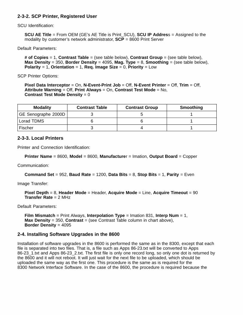
2-3-2. SCP Printer, Registered User
SCU Identification:
SCU AE Title = From OEM (GE’s AE Title is Print_SCU), SCU IP Addres s = Assigned to themodality by customer’s network administrator, SCP = 8600 Print Server
Default Parameters:
# of Copies = 1, Contrast Table = (see table below), Contrast Group = (see table below), Max Density = 350, Border Density = 4095, Mag. Type = 8, Smoothing = (see table below),Polarity = 1, Orientation = 1, Req. Image Size = 0, Priority = Low
SCP Printer Options:
Pixel Data Interceptor = On, N-Event-Print Job = Off, N-Event Printer = Off, Trim = Off,Attribute Warning = Off, Print Always = On, Contrast Test Mode = No,Contrast Test Mode Density = 0
Modality Contrast Table Contrast Group Smoothing
GE Senographe 2000D 3 5 1
Lorad TDMS 6 6 1
Fischer 3 4 1
2-3-3. Local Printers
Printer and Connection Identification:
Printer Name = 8600, Model = 8600, Manufacture r = Imation, Output Board = Copper
Communication:
Command Set = 952, Baud Rate = 1200, Data Bits = 8, Stop Bits = 1, Parity = Even
Image Transfer:
Pixel Depth = 8, Header Mode = Header, Acquire Mode = Line, Acquire Timeout = 90Transfer Rate = 2 MHz
Default Parameters:
Film Mismatch = Print Always, Interpolation Type = Imation 831, Interp Num = 1,Max Density = 350, Contrast = (see Contrast Table column in chart above), Border Density = 4095
2-4. Installing Software Upgrades in the 8600
Installation of software upgrades in the 8600 is performed the same as in the 8300, except that eachfile is separated into two files. That is, a file such as Apps 86-23.txt will be converted to Apps86-23_1.txt and Apps 86-23_2.txt. The first file is only one record long, so only one dot is returned bythe 8600 and it will not reboot. It will just wait for the next file to be uploaded, which should beuploaded the same way as the first one. This procedure is the same as is required for the8300 Network Interface Software. In the case of the 8600, the procedure is required because the
8600 internal flash memory is quite large and it takes a couple of seconds to make a backup copy ofit. The 8600 sends an X-Off to Hyperterminal to buy time, but Hyperterminal can’t react fast enoughand bits are dropped. By sending a very short first file that starts the backup copy process,Hyperterminal does not have to X-Off. By the time the second file is sent, the backup of the 8600internal flash memory is complete.
2-5. 8600 Installation Checklist
� Unpack and install the 8600 and 9410 hardware, following the procedure in Section 2 ofthe Service Manual.
� Ensure that the 8600 is configured to accept digital images from the 9410.
� Set up the 9410 with the IP Address that will put it onto the customer’s network.
� Set up the 9410 SMT SCP Printer and Local Printers parameters.
� Print a test image from the 9410.
� Send (or have the operator send) a test image from the modality work station.
� Confirm that the image is acceptable for the image parameters selected for the OEMequipment.
� Train the operators using the Operator Training Guidelines in the back of the 8600 UserGuide.
� Ask the operator to demonstrate printing a QC step wedge.
� Ask the operator to print some images that are stored on the user’s work station.
� Get image approvals from the chief radiologist who will be reading films printed on the8600.
3. Adjustments. Same as the 8300.
4. Disassembly/Reassembly. Same as the 8300.
5. Additional Information
5-1. Profile of the Mammography Customer
The majority of mammography customers, especially the first group of 8600 users, will definitely fitthe following profile. It is important for the field engineer to understand that most mammographycenters depend on high uptime and little downtime, and productivity is a key to success, especially forscreening clinics. Diagnostic centers need to see the films before the patient leaves. Most of theusers (at the beginning) will want to print images, as these are easier to compare with pastmammograms. (Comparison with previous films is common practice in mammography, and mostradiologists will not report the case if previous films are not available.) Customers are used to a fastresponse time for processing and for repair of equipment breakdowns. (Most are used to schedulePMs on x-ray equipment.) Under MQSA (Mammography Quality Standards Act), facilities cannotprocess mammograms if the processor is out of control, and customers want same day service. Weare sure they will treat the 8600 similarly and demand same day service.
In screening, the radiologist can review up to 800 films at one sitting. Artifacts of any kind tend tointerfere with the ability to quickly interpret mammograms. See new User Cleaning (paragraph 5-6)and PM (paragraph 5-7) procedures. Screening countries, and US with MQSA, are very focused onimage quality, and tend to be quality control fanatics.
5-2. Equipment Configurations
US Configuration
96-0000-1786-1 (Cat no. 1609171) DryView 8600 Laser Imager System
This should be the only configuration of the DryView 8600 that can be created by the S&SP. It is theonly configuration sold in the US. There will be no direct connects to the second input of theDryView 8600. The configuration includes:
Drop shipped from Harris:DryView 8600 Laser Imager (Cat no. 8263725)64 Mb memory (2) 32 Mb SIMMsDigital Input Module
Drop shipped from Columbia:PacsLink 9410Copcil Kit (Board/Cable/Gender changer)APC Model BK300 UPS (uninterruptable power supply)Ethernet cable (3 meter)
OUS Configuration
96-0000-1787-9 (Cat no. 8912545) DryView 8600 Laser Imager System. Includes:
DryView 8600 Laser Imager (Cat no. 1138841)Digital Input Module 64 Mb memory (2) 32 Mb SIMMs 9410 Copper Output Package (Cat no. 8983454), which includes:
96-0000-2417-2 = 9410 Base96-0000-4052-5 = Copper Output
APC Model BK300 MI UPS, 180 watt (uninterruptable power supply for 220 VAC forthe 9410, to be purchased locally in the country of installation)
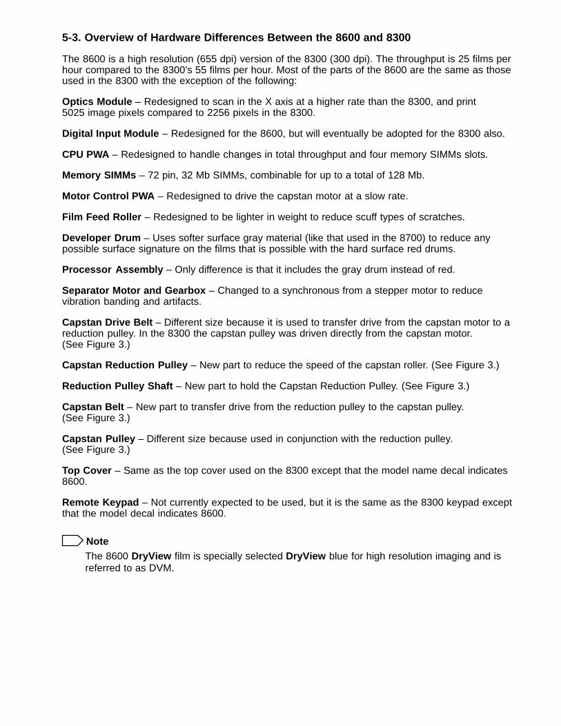
5-3. Overview of Hardware Differences Between the 8600 and 8300
The 8600 is a high resolution (655 dpi) version of the 8300 (300 dpi). The throughput is 25 films perhour compared to the 8300’s 55 films per hour. Most of the parts of the 8600 are the same as thoseused in the 8300 with the exception of the following:
Optics Module – Redesigned to scan in the X axis at a higher rate than the 8300, and print5025 image pixels compared to 2256 pixels in the 8300.
Digital Input Module – Redesigned for the 8600, but will eventually be adopted for the 8300 also.
CPU PWA – Redesigned to handle changes in total throughput and four memory SIMMs slots.
Memory SIMMs – 72 pin, 32 Mb SIMMs, combinable for up to a total of 128 Mb.
Motor Control PWA – Redesigned to drive the capstan motor at a slow rate.
Film Feed Roller – Redesigned to be lighter in weight to reduce scuff types of scratches.
Developer Drum – Uses softer surface gray material (like that used in the 8700) to reduce anypossible surface signature on the films that is possible with the hard surface red drums.
Processor Assembly – Only difference is that it includes the gray drum instead of red.
Separator Motor and Gearbox – Changed to a synchronous from a stepper motor to reducevibration banding and artifacts.
Capstan Drive Belt – Different size because it is used to transfer drive from the capstan motor to areduction pulley. In the 8300 the capstan pulley was driven directly from the capstan motor.(See Figure 3.)
Capstan Reduction Pulley – New part to reduce the speed of the capstan roller. (See Figure 3.)
Reduction Pulley Shaft – New part to hold the Capstan Reduction Pulley. (See Figure 3.)
Capstan Belt – New part to transfer drive from the reduction pulley to the capstan pulley.(See Figure 3.)
Capstan Pulley – Different size because used in conjunction with the reduction pulley.(See Figure 3.)
Top Cover – Same as the top cover used on the 8300 except that the model name decal indicates8600.
Remote Keypad – Not currently expected to be used, but it is the same as the 8300 keypad exceptthat the model decal indicates 8600.
NoteThe 8600 DryView film is specially selected DryView blue for high resolution imaging and isreferred to as DVM.
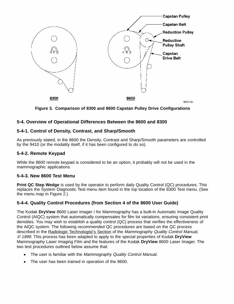
Figure 3. Comparison of 8300 and 8600 Capstan Pulley Drive Configurations
5-4. Overview of Operational Differences Between the 8600 and 8300
5-4-1. Control of Density, Contrast, and Sharp/Smooth
As previously stated, in the 8600 the Density, Contrast and Sharp/Smooth parameters are controlledby the 9410 (or the modality itself, if it has been configured to do so).
5-4-2. Remote Keypad
While the 8600 remote keypad is considered to be an option, it probably will not be used in themammographic applications.
5-4-3. New 8600 Test Menu
Print QC Step Wedge is used by the operator to perform daily Quality Control (QC) procedures. Thisreplaces the System Diagnostic Test menu item found in the top location of the 8300 Test menu. (Seethe menu map in Figure 2.)
5-4-4. Quality Control Procedures (from Section 4 of the 8600 User Guide)
The Kodak DryView 8600 Laser Imager / for Mammography has a built-in Automatic Image QualityControl (AIQC) system that automatically compensates for film lot variations, ensuring consistent printdensities. You may wish to establish a quality control (QC) process that verifies the effectiveness ofthe AIQC system. The following recommended QC procedures are based on the QC processdescribed in the Radiologic Technologist’s Section of the Mammography Quality Control Manual, � 1999. This process has been adapted to apply to the special properties of Kodak DryViewMammography Laser Imaging Film and the features of the Kodak DryView 8600 Laser Imager. Thetwo test procedures outlined below assume that:
� The user is familiar with the Mammography Quality Control Manual.
� The user has been trained in operation of the 8600.
Running a QC Baseline Test
This test sets up a baseline set of film parameter values which will be used as a standard forcomparison in daily quality control tests. The baseline test must be run when the 8600 is firstinstalled, and it must be repeated every time a box of film with a different emulsion number is used.
1. Apply power to the 8600 and allow it to warm to READY, as indicated on the local panel. The8600 will print a film calibration sheet, to put its Automatic Image Quality Control (AIQC) system incontrol.
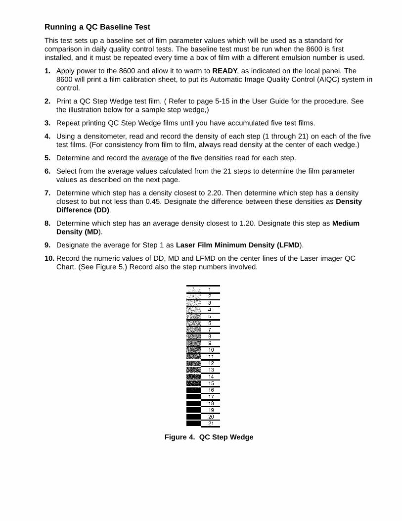
2. Print a QC Step Wedge test film. ( Refer to page 5-15 in the User Guide for the procedure. Seethe illustration below for a sample step wedge,)
3. Repeat printing QC Step Wedge films until you have accumulated five test films.
4. Using a densitometer, read and record the density of each step (1 through 21) on each of the fivetest films. (For consistency from film to film, always read density at the center of each wedge.)
5. Determine and record the average of the five densities read for each step.
6. Select from the average values calculated from the 21 steps to determine the film parametervalues as described on the next page.
7. Determine which step has a density closest to 2.20. Then determine which step has a densityclosest to but not less than 0.45. Designate the difference between these densities as DensityDifference (DD) .
8. Determine which step has an average density closest to 1.20. Designate this step as MediumDensity (MD ).
9. Designate the average for Step 1 as Laser Film Minimum Density (LFMD ).
10. Record the numeric values of DD, MD and LFMD on the center lines of the Laser imager QCChart. (See Figure 5.) Record also the step numbers involved.
Figure 4. QC Step Wedge
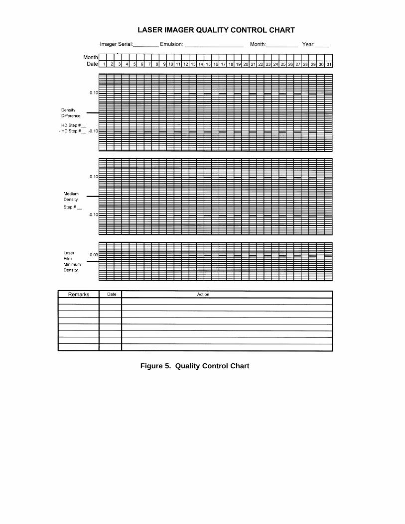
Figure 5. Quality Control Chart
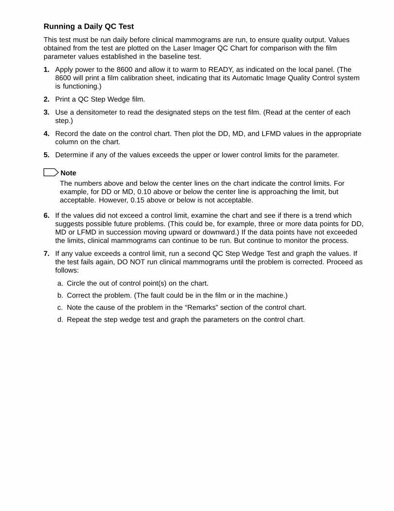
Running a Daily QC Test
This test must be run daily before clinical mammograms are run, to ensure quality output. Valuesobtained from the test are plotted on the Laser Imager QC Chart for comparison with the filmparameter values established in the baseline test.
1. Apply power to the 8600 and allow it to warm to READY, as indicated on the local panel. (The8600 will print a film calibration sheet, indicating that its Automatic Image Quality Control systemis functioning.)
2. Print a QC Step Wedge film.
3. Use a densitometer to read the designated steps on the test film. (Read at the center of eachstep.)
4. Record the date on the control chart. Then plot the DD, MD, and LFMD values in the appropriatecolumn on the chart.
5. Determine if any of the values exceeds the upper or lower control limits for the parameter.
NoteThe numbers above and below the center lines on the chart indicate the control limits. Forexample, for DD or MD, 0.10 above or below the center line is approaching the limit, butacceptable. However, 0.15 above or below is not acceptable.
6. If the values did not exceed a control limit, examine the chart and see if there is a trend whichsuggests possible future problems. (This could be, for example, three or more data points for DD,MD or LFMD in succession moving upward or downward.) If the data points have not exceededthe limits, clinical mammograms can continue to be run. But continue to monitor the process.
7. If any value exceeds a control limit, run a second QC Step Wedge Test and graph the values. Ifthe test fails again, DO NOT run clinical mammograms until the problem is corrected. Proceed asfollows:
a. Circle the out of control point(s) on the chart.
b. Correct the problem. (The fault could be in the film or in the machine.)
c. Note the cause of the problem in the “Remarks” section of the control chart.
d. Repeat the step wedge test and graph the parameters on the control chart.
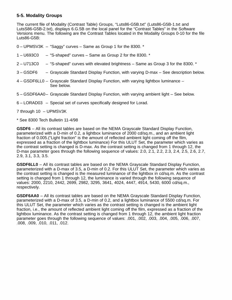
5-5. Modality Groups
The current file of Modality (Contrast Table) Groups, “Luts86-G5B.txt” (Luts86-G5B-1.txt andLutsS86-G5B-2.txt), displays 6.G.5B on the local panel for the “Contrast Tables” in the SoftwareVersions menu. The following are the Contrast Tables located in the Modality Groups 0-10 for the fileLuts86-G5B:
0 – UPMSV3K – “Saggy” curves – Same as Group 1 for the 8300. *
1 – U693C0 – “S-shaped” curves – Same as Group 2 for the 8300. *
2 – U713C0 – “S-shaped” curves with elevated brightness – Same as Group 3 for the 8300. *
3 – GSDF6 – Grayscale Standard Display Function, with varying D-max – See description below.
4 – GSDF6LL0 – Grayscale Standard Display Function, with varying lightbox luminance –See below.
5 – GSDF6AA0– Grayscale Standard Display Function, with varying ambient light – See below.
6 – LORAD03 – Special set of curves specifically designed for Lorad.
7 through 10 – UPMSV3K
* See 8300 Tech Bulletin 11-4/98
GSDF6 – All its contrast tables are based on the NEMA Grayscale Standard Display Function,parameterized with a D-min of 0.2, a lightbox luminance of 2000 cd/sq.m., and an ambient lightfraction of 0.005.(“Light fraction” is the amount of reflected ambient light coming off the film,expressed as a fraction of the lightbox luminance) For this ULUT Set, the parameter which varies asthe contrast setting is changed is D-max. As the contrast setting is changed from 1 through 12, theD-max parameter goes through the following sequence of values: 2.0, 2.1, 2.2, 2.3, 2.4, 2.5, 2.6, 2.7,2.9, 3.1, 3.3, 3.5.
GSDF6LL0 – All its contrast tables are based on the NEMA Grayscale Standard Display Function,parameterized with a D-max of 3.5, a D-min of 0.2. For this ULUT Set, the parameter which varies asthe contrast setting is changed is the measured luminance of the lightbox in cd/sq.m. As the contrastsetting is changed from 1 through 12, the luminance is varied through the following sequence ofvalues: 2000, 2210, 2442, 2699, 2982, 3295, 3641, 4024, 4447, 4914, 5430, 6000 cd/sq.m.,respectively.
GSDF6AA0 – All its contrast tables are based on the NEMA Grayscale Standard Display Function,parameterized with a D-max of 3.5, a D-min of 0.2, and a lightbox luminance of 5500 cd/sq.m. Forthis ULUT Set, the parameter which varies as the contrast setting is changed is the ambient lightfraction, i.e., the amount of reflected ambient light coming off the film, expressed as a fraction of thelightbox luminance. As the contrast setting is changed from 1 through 12, the ambient light fractionparameter goes through the following sequence of values: .001, .002, .003, .004, .005, .006, .007,.008, .009, .010, .011, .012.
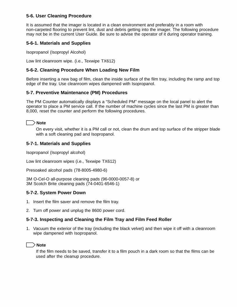
5-6. User Cleaning Procedure
It is assumed that the imager is located in a clean environment and preferably in a room withnon-carpeted flooring to prevent lint, dust and debris getting into the imager. The following proceduremay not be in the current User Guide. Be sure to advise the operator of it during operator training.
5-6-1. Materials and Supplies
Isopropanol (Isopropyl Alcohol)
Low lint cleanroom wipe. (i.e., Texwipe TX612)
5-6-2. Cleaning Procedure When Loading New Film
Before inserting a new bag of film, clean the inside surface of the film tray, including the ramp and topedge of the tray. Use cleanroom wipes dampened with Isopropanol.
5-7. Preventive Maintenance (PM) Procedures
The PM Counter automatically displays a “Scheduled PM” message on the local panel to alert theoperator to place a PM service call. If the number of machine cycles since the last PM is greater than8,000, reset the counter and perform the following procedures.
NoteOn every visit, whether it is a PM call or not, clean the drum and top surface of the stripper bladewith a soft cleaning pad and Isopropanol.
5-7-1. Materials and Supplies
Isopropanol (Isopropyl alcohol)
Low lint cleanroom wipes (i.e., Texwipe TX612)
Presoaked alcohol pads (78-8005-4980-6)
3M O-Cel-O all-purpose cleaning pads (96-0000-0057-8) or 3M Scotch Brite cleaning pads (74-0401-6546-1)
5-7-2. System Power Down
1. Insert the film saver and remove the film tray.
2. Turn off power and unplug the 8600 power cord.
5-7-3. Inspecting and Cleaning the Film Tray and Film Feed Roller
1. Vacuum the exterior of the tray (including the black velvet) and then wipe it off with a cleanroomwipe dampened with Isopropanol.
NoteIf the film needs to be saved, transfer it to a film pouch in a dark room so that the films can beused after the cleanup procedure.
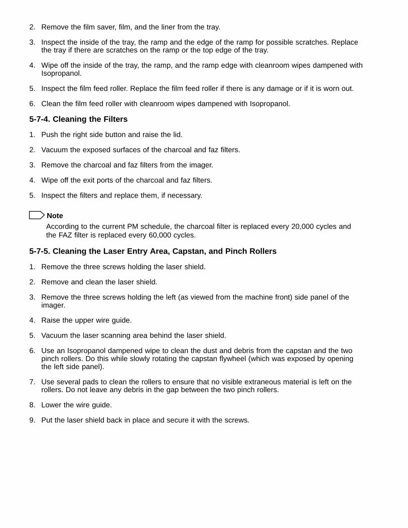
2. Remove the film saver, film, and the liner from the tray.
3. Inspect the inside of the tray, the ramp and the edge of the ramp for possible scratches. Replacethe tray if there are scratches on the ramp or the top edge of the tray.
4. Wipe off the inside of the tray, the ramp, and the ramp edge with cleanroom wipes dampened withIsopropanol.
5. Inspect the film feed roller. Replace the film feed roller if there is any damage or if it is worn out.
6. Clean the film feed roller with cleanroom wipes dampened with Isopropanol.
5-7-4. Cleaning the Filters
1. Push the right side button and raise the lid.
2. Vacuum the exposed surfaces of the charcoal and faz filters.
3. Remove the charcoal and faz filters from the imager.
4. Wipe off the exit ports of the charcoal and faz filters.
5. Inspect the filters and replace them, if necessary.
NoteAccording to the current PM schedule, the charcoal filter is replaced every 20,000 cycles andthe FAZ filter is replaced every 60,000 cycles.
5-7-5. Cleaning the Laser Entry Area, Capstan, and Pinch Rollers
1. Remove the three screws holding the laser shield.
2. Remove and clean the laser shield.
3. Remove the three screws holding the left (as viewed from the machine front) side panel of theimager.
4. Raise the upper wire guide.
5. Vacuum the laser scanning area behind the laser shield.
6. Use an Isopropanol dampened wipe to clean the dust and debris from the capstan and the twopinch rollers. Do this while slowly rotating the capstan flywheel (which was exposed by openingthe left side panel).
7. Use several pads to clean the rollers to ensure that no visible extraneous material is left on therollers. Do not leave any debris in the gap between the two pinch rollers.
8. Lower the wire guide.
9. Put the laser shield back in place and secure it with the screws.
5-7-6. Cleaning the Scoop and other Exposed Areas
1. Raise the upper wire guide and pull down the lower wire guide.
2. Vacuum all the exposed surfaces, including: scoop, scoop cover plate, film tray housing,separator roller, film entrance guide, etc.
3. Use the alcohol dampened cleanroom wipe to wipe all the exposed areas.
4. Access and clean the top end of the scoop as much as possible.
5. Raise and lock the lower wire guide, and lower and lock the upper wire guide.
5-7-7. Cleaning the Processor
5-7-7-1. Removing the Processor
1. Remove the right side panel of the imager.
2. Remove all the processor cables attached to the 8600 system boards.
3. Remove the four screws holding the processor assembly.
4. Remove the processor assembly from the imager.
5. Vacuum the exposed area in the imager after the processor assembly has been removed.
6. Open the processor hinge and remove the processor half (procedure 4-7-2 in the 8300 ServiceManual) that pivots on the screws.
5-7-7-2. Cleaning the Drum
1. Rotate the processor drum wheel on the left side while cleaning the processor drum surface withalcohol dampened cleanroom wipes.
NoteDO NOT use 3M Troubleshooter to clean. Use full strength Isopropanol.
2. Use multiple wipes to ensure that the drum surface is clean.
5-7-7-3. Cleaning the Processor Rollers
1. Remove the processor drum (procedure 4-7-3 in the 8300 Service Manual).
2. Inspect the roller assembly and behind the rollers. If these areas show significant fazaccumulation, remove the rollers for cleaning.
3. Use the Isopropanol dampened wipes to clean the upper and bottom pressure rollers. UseAll-Purpose cleaning pads or 3M Scotch Brite pads to remove tough stains from the rollers.
! CautionTo prevent deplating of the rollers, do not rub rub the rollers hard with the cleaning pads.
4. Clean the metal surfaces behind the rollers using cleanroom wipes and Isopropanol. UseIsopropanol dampened cleaning pads to remove tough stains.
5. If deplating or degradation of the rollers is evident, replace them.
5-7-7-4. Cleaning the Stripper Blade
1. Clean the metal surfaces of the stripper blade (top and bottom), using cleanroom wipes andIsopropanol.
2. Ensure that all deposits on the bottom of the blade are removed by using an all-purpose cleaningpad. If deposits build up they can damage the drum.
NoteIf the felt pad assemblies are not to be replaced during the PM, do not allow cleaning solutionsto touch them.
5-7-7-5. Cleaning the Film Guide
Remove and separate the Ultem film guide at the processor entrance (procedure 4-7-7 in the 8300Service Manual), and clean with Isopropanol and cleanroom wipes or all-purpose cleaning pads.
5-7-7-6. Cleaning the Densitometer
1. Separate the densitometer assembly by removing the horizontally oriented screws from bothends.
NoteTake care not to lose the spacer bars.
2. Clean the inside surfaces with Isopropanol soaked cleanroom wipes.
3. Clean the sensor lens on the upper surface with a presoaked alcohol pad. Take care not toscratch the surface.
4. Clean the glass lens with a presoaked alcohol pad.
NoteDuring reassembly, make sure that the actuator arm on the exit sensor is in the slot. Also, do notforget to put back the spacers between the two halves of the densitometer assembly.
5-7-7-7. Cleaning the Entrance and Exit Rollers
Rotate and clean the processor entrance and exit rollers with Isopropanol soaked cleanroom wipes.
5-7-8. Reassembly
After PM, reassemble the system.
6. Theory of Operation. Sequence flow charts are the same as for the 8300.
7. Diagrams. A new diagram will be supplied in the 8600 Service Manual.
8. Troubleshooting
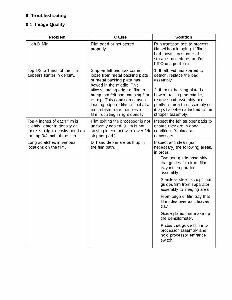
8-1. Image Quality
Problem Cause Solution
High D-Min Film aged or not storedproperly.
Run transport test to processfilm without imaging. If film isbad, advise customer ofstorage procedures and/orFIFO usage of film.
Top 1/2 to 1 inch of the filmappears lighter in density.
Stripper felt pad has comeloose from metal backing plateor metal backing plate hasbowed in the middle. Thisallows leading edge of film tobump into felt pad, causing filmto hop. This condition causesleading edge of film to cool at amuch faster rate than rest offilm, resulting in light density.
1. If felt pad has started todetach, replace the padassembly.
2. If metal backing plate isbowed, raising the middle,remove pad assembly andgently re-form the assembly soit lays flat when attached to thestripper assembly.
Top 4 inches of each film isslightly lighter in density orthere is a light density band onthe top 3/4 inch of the film.
Film exiting the processor is notuniformly cooled. (Film is notstaying in contact with lower feltstripper pad.)
Inspect the felt stripper pads toensure they are in goodcondition. Replace asnecessary.
Long scratches in variouslocations on the film.
Dirt and debris are built up inthe film path.
Inspect and clean (asnecessary) the following areas,in order:
Two part guide assemblythat guides film from filmtray into separatorassembly.
Stainless steel “scoop” thatguides film from separatorassembly to imaging area.
Front edge of film tray thatfilm rides over as it leavestray.
Guide plates that make upthe densitometer.
Plates that guide film intoprocessor assembly andhold processor entranceswitch.
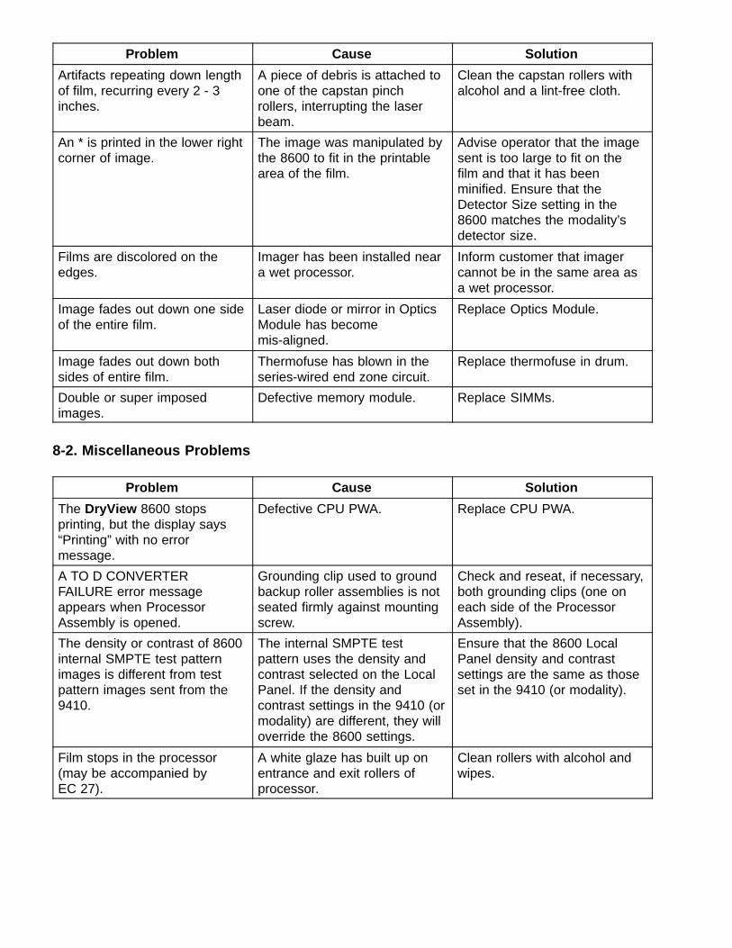
Problem Cause Solution
Artifacts repeating down lengthof film, recurring every 2 - 3inches.
A piece of debris is attached toone of the capstan pinchrollers, interrupting the laserbeam.
Clean the capstan rollers withalcohol and a lint-free cloth.
An * is printed in the lower rightcorner of image.
The image was manipulated bythe 8600 to fit in the printablearea of the film.
Advise operator that the imagesent is too large to fit on thefilm and that it has beenminified. Ensure that theDetector Size setting in the8600 matches the modality’sdetector size.
Films are discolored on theedges.
Imager has been installed neara wet processor.
Inform customer that imagercannot be in the same area asa wet processor.
Image fades out down one sideof the entire film.
Laser diode or mirror in OpticsModule has becomemis-aligned.
Replace Optics Module.
Image fades out down bothsides of entire film.
Thermofuse has blown in theseries-wired end zone circuit.
Replace thermofuse in drum.
Double or super imposedimages.
Defective memory module. Replace SIMMs.
8-2. Miscellaneous Problems
Problem Cause Solution
The DryView 8600 stopsprinting, but the display says“Printing” with no errormessage.
Defective CPU PWA. Replace CPU PWA.
A TO D CONVERTERFAILURE error messageappears when ProcessorAssembly is opened.
Grounding clip used to groundbackup roller assemblies is notseated firmly against mountingscrew.
Check and reseat, if necessary,both grounding clips (one oneach side of the ProcessorAssembly).
The density or contrast of 8600internal SMPTE test patternimages is different from testpattern images sent from the9410.
The internal SMPTE testpattern uses the density andcontrast selected on the LocalPanel. If the density andcontrast settings in the 9410 (ormodality) are different, they willoverride the 8600 settings.
Ensure that the 8600 LocalPanel density and contrastsettings are the same as thoseset in the 9410 (or modality).
Film stops in the processor(may be accompanied byEC 27).
A white glaze has built up onentrance and exit rollers ofprocessor.
Clean rollers with alcohol andwipes.
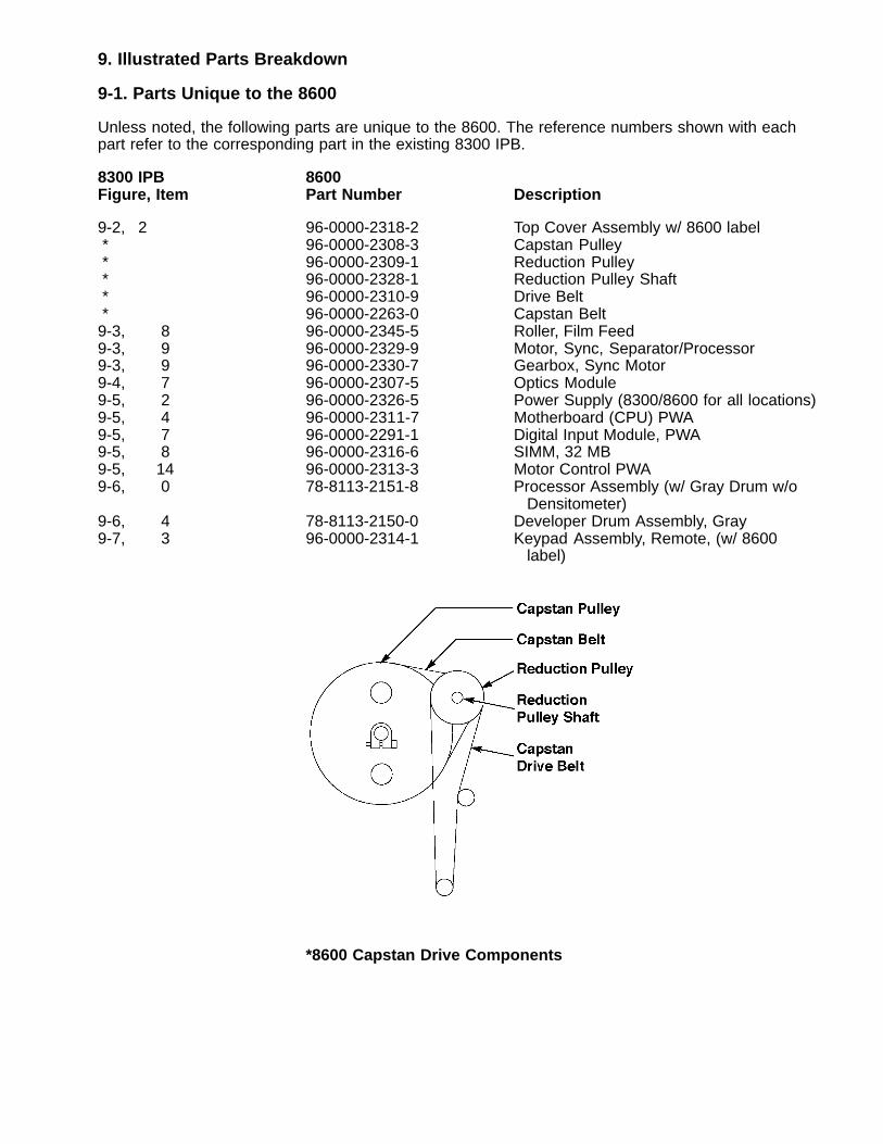
9. Illustrated Parts Breakdown
9-1. Parts Unique to the 8600
Unless noted, the following parts are unique to the 8600. The reference numbers shown with eachpart refer to the corresponding part in the existing 8300 IPB.
8300 IPB 8600Figure, Item Part Number Description
9-2, 2 96-0000-2318-2 Top Cover Assembly w/ 8600 label * 96-0000-2308-3 Capstan Pulley * 96-0000-2309-1 Reduction Pulley * 96-0000-2328-1 Reduction Pulley Shaft * 96-0000-2310-9 Drive Belt * 96-0000-2263-0 Capstan Belt9-3, 8 96-0000-2345-5 Roller, Film Feed9-3, 9 96-0000-2329-9 Motor, Sync, Separator/Processor9-3, 9 96-0000-2330-7 Gearbox, Sync Motor9-4, 7 96-0000-2307-5 Optics Module9-5, 2 96-0000-2326-5 Power Supply (8300/8600 for all locations)9-5, 4 96-0000-2311-7 Motherboard (CPU) PWA9-5, 7 96-0000-2291-1 Digital Input Module, PWA9-5, 8 96-0000-2316-6 SIMM, 32 MB9-5, 14 96-0000-2313-3 Motor Control PWA9-6, 0 78-8113-2151-8 Processor Assembly (w/ Gray Drum w/o Densitometer)9-6, 4 78-8113-2150-0 Developer Drum Assembly, Gray9-7, 3 96-0000-2314-1 Keypad Assembly, Remote, (w/ 8600
label)
*8600 Capstan Drive Components
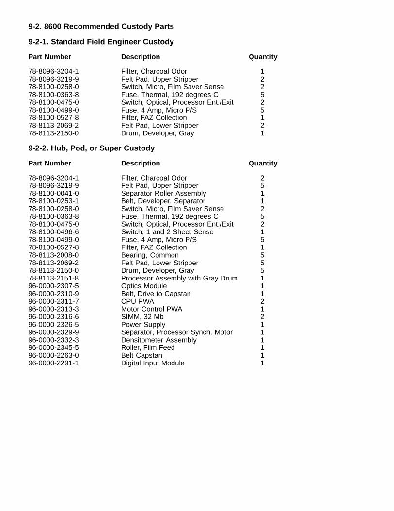
9-2. 8600 Recommended Custody Parts
9-2-1. Standard Field Engineer Custody
Part Number Description Quantity
78-8096-3204-1 Filter, Charcoal Odor 178-8096-3219-9 Felt Pad, Upper Stripper 278-8100-0258-0 Switch, Micro, Film Saver Sense 278-8100-0363-8 Fuse, Thermal, 192 degrees C 578-8100-0475-0 Switch, Optical, Processor Ent./Exit 278-8100-0499-0 Fuse, 4 Amp, Micro P/S 578-8100-0527-8 Filter, FAZ Collection 178-8113-2069-2 Felt Pad, Lower Stripper 278-8113-2150-0 Drum, Developer, Gray 1
9-2-2. Hub, Pod, or Super Custody
Part Number Description Quantity
78-8096-3204-1 Filter, Charcoal Odor 278-8096-3219-9 Felt Pad, Upper Stripper 578-8100-0041-0 Separator Roller Assembly 178-8100-0253-1 Belt, Developer, Separator 178-8100-0258-0 Switch, Micro, Film Saver Sense 278-8100-0363-8 Fuse, Thermal, 192 degrees C 578-8100-0475-0 Switch, Optical, Processor Ent./Exit 278-8100-0496-6 Switch, 1 and 2 Sheet Sense 178-8100-0499-0 Fuse, 4 Amp, Micro P/S 578-8100-0527-8 Filter, FAZ Collection 178-8113-2008-0 Bearing, Common 578-8113-2069-2 Felt Pad, Lower Stripper 578-8113-2150-0 Drum, Developer, Gray 578-8113-2151-8 Processor Assembly with Gray Drum 196-0000-2307-5 Optics Module 196-0000-2310-9 Belt, Drive to Capstan 196-0000-2311-7 CPU PWA 296-0000-2313-3 Motor Control PWA 196-0000-2316-6 SIMM, 32 Mb 296-0000-2326-5 Power Supply 196-0000-2329-9 Separator, Processor Synch. Motor 196-0000-2332-3 Densitometer Assembly 196-0000-2345-5 Roller, Film Feed 196-0000-2263-0 Belt Capstan 196-0000-2291-1 Digital Input Module 1
Kodak Health Imaging1 Imation WayDiscovery 4B-74Oakdale, MN 55128http://www.kodak.com
Printed in the U.S.A. Kodak 2000 January
Technical Bulletin 01/26/00
DryView Laser ImagingSystem / for Mammography8600
1-1/00 “Fail to Get DICOM Printer Status” Modality ErrorMessage
Problem : A new installation with a GE FFDM system passes successful Pings and Send Echocommands, but the error message “Fail to Get DICOM Printer Status” displays on the modality’smonitor when a Print command is sent to the 8600/9410.
Cause : The wrong modality AE Title was entered for the Registered User on the 9410. It wasoriginally documented that “Print_SCU” was the default AE Title for GE Senographe 2000D. However,this is not always the case.
Solution : Obtain the proper AE Title from the GE representative and enter it for the Registered Userin the SCP Printer file.
2-1/00 QC Step Wedge Density Measurements Not asExpected
Problem : The density measurements of specific steps in the QC step wedge are not what the OEMexpects for the (Contrast) Modality Group selected in the 8600 or 9410.
Cause : The selected Modality Group is not the correct group of contrast tables (those recommendedby the OEM). The groups have been renumbered since you first received information on groupnumbering in the original 8600 Training Bulletin. The Modality Group numbers now range from 1-11instead of 0-10 as in the past.
Solution : Change the Modality Group number to reflect the desired group. In most cases, this is assimple as increasing the number by one. For example, if group 5 was used when the groups werelabeled 0-10, group 6 will need to be selected now that the groups are labeled 1-11.
3-1/00 Frequent Error Code 27’sProblem : Films stop intermittently in the Processor at various positions for no apparent reasoncausing EC27 to be displayed.
Cause : The system software may have timed out because the film took too long to travel through theProcessor.
Solution : First adjust the Processor drive belt to specification (paragraph 3-12 in the ServiceManual). Then remove the non-driven entrance and exit rollers and clean the rubber surface of therollers with alcohol. Also clean the roller shafts and associated bearings.
4-1/00 Power Distribution Error and/or Laser BoardFailure with 9410 Connected
Problem : A power distribution error and/or a Laser Board Failure message appears on the 8600local panel when a 9410 is connected to the host control connector on the 8600.
Cause : The 9410 may be loading down the 8600 power supply.
Solution : Check the position of the +/– 12V CTS/RTS Switch on the Digital Input Module of the8600. It should be set in the CTS/RTS position. (The +/– 12V position is for keypad control and theCTS/RTS position is for host control.) To change the position of the switch, power off and use aball-point pen to press the white center portion down on the end closest to the CTS/RTS marking onthe circuit board.

Health Imaging
Technical Bulletin 8600
Eastman Kodak Company
1 Imation WayOakdale, MN 55128
Health Imaging Products
http://www.kodak.comPrinted in the U.S.A.© Kodak 2000 Sept.
5-9/00 Clicking Sound from Left Side of Imager
Problem:Intermittent clicking sound from the left side of the imager.
Cause:The Compound Pulley (78-8100-0410-7), which transfers power from the main drive belt to the Separator Assembly, is made up of a black plastic pulley housing and two bearings. If one of the bearings starts to deteriorate, it will cause the pulley to emit an intermittent clicking sound.
Solution:Replace the bad bearing. The bearings are the same Common Bearing (78-8113-2008-0) used throughout the imager, and can be replaced individually. If the Pulley Mounting Shaft (78-8100-0614-4) has been damaged by the bearing, it also can be easily replaced.
6-9/00 Thumping Sound from Left Side of Imager
Problem:Occasional thumping sound from the left side of the imager.
Cause:The main drive belt, which connects the main stepper motor to the Separator Assembly and the Processor Assembly, can skip a tooth from time to time, causing the thumping sound. This skipping of teeth, which can be caused by a loose belt, results in belt wear. The belt wear is evidenced by a buildup of black �powder� (belt particles) on the left side frame and base plate. If the problem condition has existed for a long time, the black powder can build up on the teeth of the Compound (two part) Pulley. This buildup on the pulley can cause the belt to continue to skip, even after its tension has been adjusted.
Solution:Tighten the tension of the main drive belt, as necessary, by adjusting the eccentric. Check for powder buildup on the Compound Pulley, and clean the pulley, as necessary. (The Compound Pulley is black, so the powder buildup is not easy to see.)
7-9/00 New 9410 Version 1.3 Menu Items Applicable to the 8600
The PACS Link 9410 units currently being shipped with 8600 Laser Imagers all have SMT Version 1.3 software installed. Consequently, the 8600s need to have system software Version 2.4 installed. If you are at a new installation and the 8600 does not have Version 2.4 software, contact TAC for a copy or upload it from the Service CD-ROM, Rev. S. Use the software installation procedure provided in the Installation section of the 8600 Service Manual.
While SMT Version 1.1 had control only over Density, Contrast, and Smoothing in the 8600, SMT Version 1.3 can control those three parameters plus Modality (Contrast) Group, Smoothing (Kernel) Group, and Gamma Table. Additional menu items have been added to the Registered Users menu of SCP Printers and to the Local Printers menu to accommodate the new capabilities. Accordingly, the following new menu items must be configured at installation.
Registered UsersTFT/ULUT - Not configurable for the 8600Gamma Table = Linear in TransmittanceContrast Group = 6 (for GE Senographe 2000D). For other OEMs see Table 2-4 in the 8600 Service Manual.Kernel Group = 1
Local PrintersInstalled TFT/ULUT - Not configurable for the 8600
All other menu items should be configured as noted in the Installation section of the 8600 Service Manual.
8-9/00 Thin Horizontal Line Across Width of Film
Problem:A horizontal line appears across the film, about 5-1/2 inches from the top. It may look like image data is missing in one or two scan lines. The line, which may be intermittent, occurs across the entire width of the film, traversing both the image and the borders.
Cause:The operator may have removed a jam and attempted to snap the upper film guide back into place, but only one side got latched. The line is caused by the film hesitating while it is being imaged, as it enters the processor assembly.
Solution:As a phone fix, ask the operator to reseat the upper film guide and ensure that it is snapped into place on both sides.
Health Imaging
Technical Bulletin 8600/8610
Eastman Kodak Company
1 Imation WayOakdale, MN 55128
Health Imaging Products
http://www.kodak.comPrinted in the U.S.A.© Kodak 2000 Dec.
9-12/00 8610 Laser Imaging Training BulletinIntroductionThis training document is intended for FEs previously trained on the Kodak DryView 8300 and 8600, who have had some hands-on experience on both models. In addition, the FEs must have been trained on the Kodak PACS Link 9410 Acquisition System. The information supplied in this bulletin is specific to the installation and operation of the Kodak DryView 8610 Laser Imaging System / for Mammography. For more detailed information on the 9410, please see the PACS Link 9410 Acquisition System ServiceManual.
Functional Differences Between 8610 and 8600There are two main operational differences between the 8610 and the 8600. The 8610 prints films at a rate of 40 films per hour, compared to the 25 films per hour that the 8600 produces. In addition, the 8610 prints images from 12-bit input data, compared to the 8-bit input data limitation of the 8600 (see paragraph 2-12 in the attached Installation instructions). Because of these features, the 8610 has replaced the 8600, which is now out of production.
Parts DifferencesSeven spare parts are unique to the 8610. These are listed below. The rest of the 8610 parts are identical to the parts found in the IPB section of the 8600 Service Manual. Please note that the 8610 is shipped with 128 Mb of image memory, compared to 64 Mb in the 8600. The reference numbers shown with each part refer to the corresponding part in the current 8600 IPB.
8600 IPB 8610Figure, Item Part Number Description8-2, 2 6E8532 Top Cover Assembly w/ 8610 label8-3 3 78-8113-2189-8 Capstan Stepper Motor8-4, 7 74-0401-8003-1 Optics Module8-5, 4 78-8113-2195-5 Motherboard (CPU) PWA8-5, 7 78-8113-2176-5 Digital Input Module, PWA8-5, 8 78-8113-2187-2 SIMM, 128 MB8-5, 12 78-8113-2184-9 Motor Control PWA
Service ManualThe 8600 Service Manual is being replaced by the 8600/8610 Service Manual, which will be included in the next revision of the Service Collection CD-ROM, Rev. T. The following pages are from the Installation section of the new 8600/8610 Service Manual.
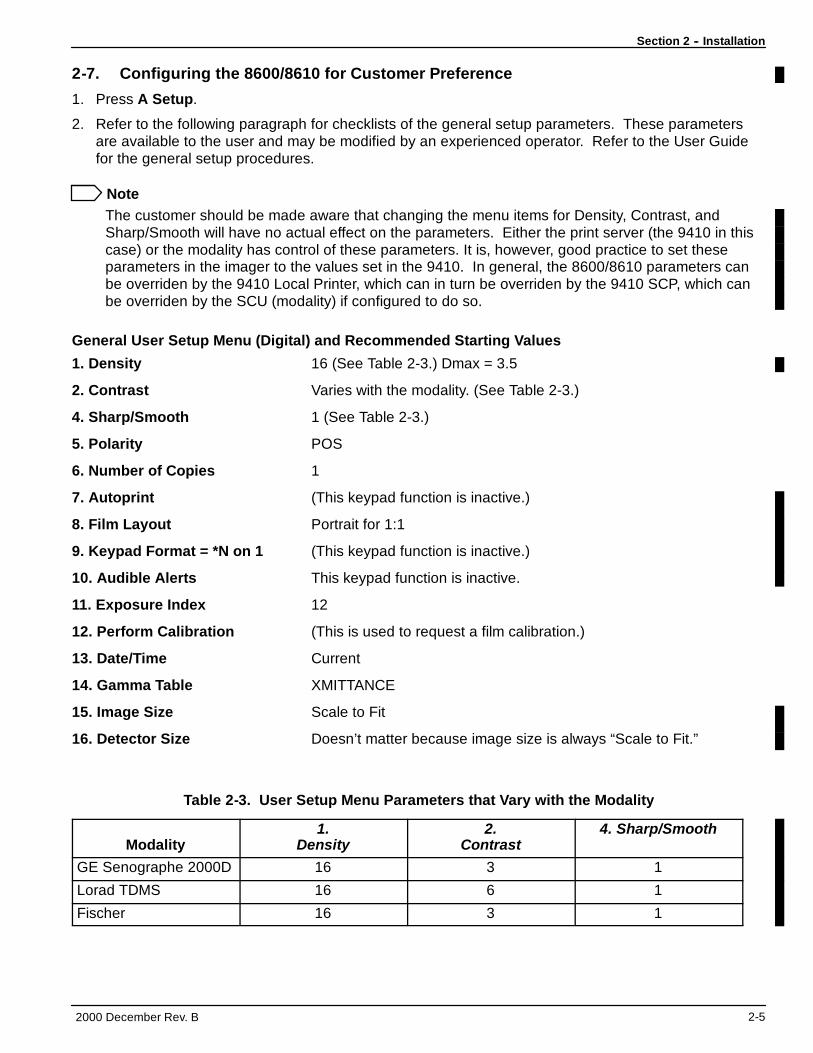
Section 2 -- Installation
2000 December Rev. B 2-5
2-7. Configuring the 8600/8610 for Customer Preference
1. Press A Setup.
2. Refer to the following paragraph for checklists of the general setup parameters. These parametersare available to the user and may be modified by an experienced operator. Refer to the User Guidefor the general setup procedures.
NoteThe customer should be made aware that changing the menu items for Density, Contrast, andSharp/Smooth will have no actual effect on the parameters. Either the print server (the 9410 in thiscase) or the modality has control of these parameters. It is, however, good practice to set theseparameters in the imager to the values set in the 9410. In general, the 8600/8610 parameters canbe overriden by the 9410 Local Printer, which can in turn be overriden by the 9410 SCP, which canbe overriden by the SCU (modality) if configured to do so.
General User Setup Menu (Digital) and Recommended Starting Values
1. Density 16 (See Table 2-3.) Dmax = 3.5
2. Contrast Varies with the modality. (See Table 2-3.)
4. Sharp/Smooth 1 (See Table 2-3.)
5. Polarity POS
6. Number of Copies 1
7. Autoprint (This keypad function is inactive.)
8. Film Layout Portrait for 1:1
9. Keypad Format = *N on 1 (This keypad function is inactive.)
10. Audible Alerts This keypad function is inactive.
11. Exposure Index 12
12. Perform Calibration (This is used to request a film calibration.)
13. Date/Time Current
14. Gamma Table XMITTANCE
15. Image Size Scale to Fit
16. Detector Size Doesn’t matter because image size is always “Scale to Fit.”
Table 2-3. User Setup Menu Parameters that Vary with the Modality
Modality1.
Density2.
Contrast4. Sharp/Smooth
GE Senographe 2000D 16 3 1
Lorad TDMS 16 6 1
Fischer 16 3 1
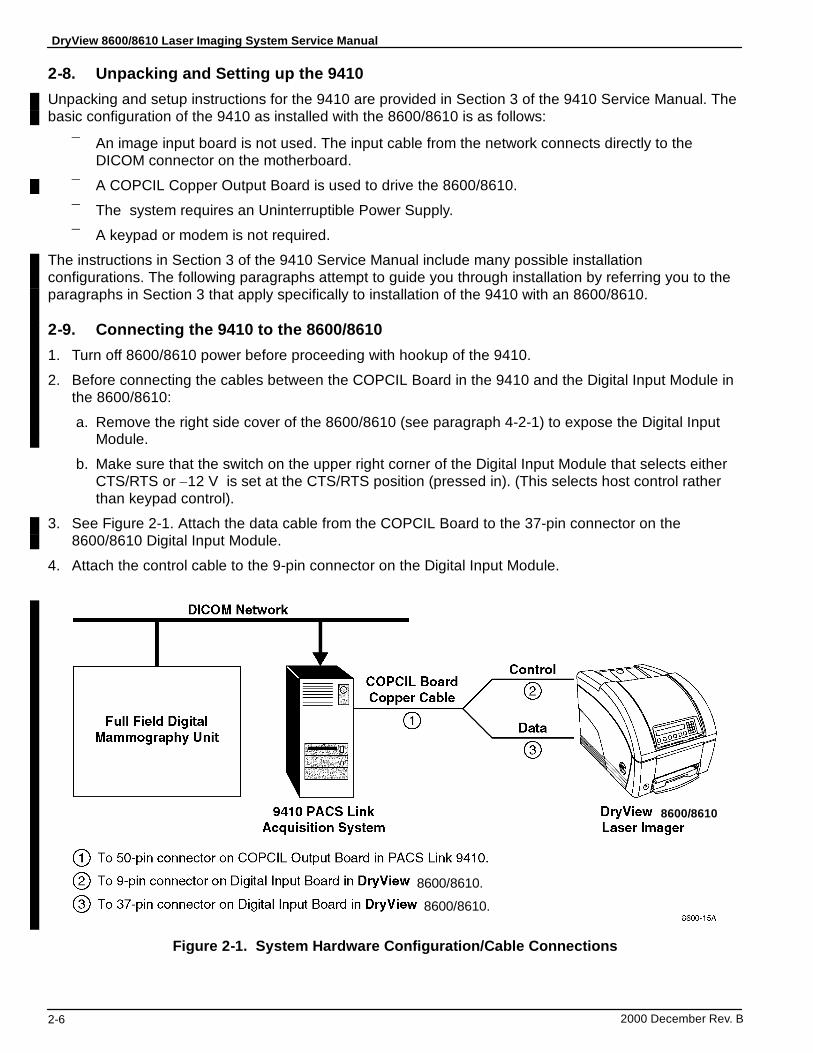
DryView 8600/8610 Laser Imaging System Service Manual
2000 December Rev. B2-6
2-8. Unpacking and Setting up the 9410
Unpacking and setup instructions for the 9410 are provided in Section 3 of the 9410 Service Manual. Thebasic configuration of the 9410 as installed with the 8600/8610 is as follows:
¯ An image input board is not used. The input cable from the network connects directly to theDICOM connector on the motherboard.
¯ A COPCIL Copper Output Board is used to drive the 8600/8610.
¯ The system requires an Uninterruptible Power Supply.
¯ A keypad or modem is not required.
The instructions in Section 3 of the 9410 Service Manual include many possible installationconfigurations. The following paragraphs attempt to guide you through installation by referring you to theparagraphs in Section 3 that apply specifically to installation of the 9410 with an 8600/8610.
2-9. Connecting the 9410 to the 8600/8610
1. Turn off 8600/8610 power before proceeding with hookup of the 9410.
2. Before connecting the cables between the COPCIL Board in the 9410 and the Digital Input Module inthe 8600/8610:
a. Remove the right side cover of the 8600/8610 (see paragraph 4-2-1) to expose the Digital InputModule.
b. Make sure that the switch on the upper right corner of the Digital Input Module that selects eitherCTS/RTS or ±12 V is set at the CTS/RTS position (pressed in). (This selects host control ratherthan keypad control).
3. See Figure 2-1. Attach the data cable from the COPCIL Board to the 37-pin connector on the8600/8610 Digital Input Module.
4. Attach the control cable to the 9-pin connector on the Digital Input Module.
8600/8610
8600/8610.
8600/8610.
Figure 2-1. System Hardware Configuration/Cable Connections
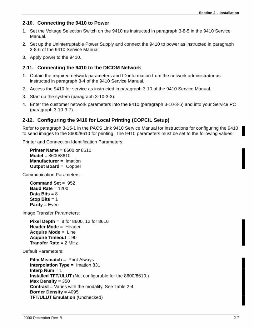
Section 2 -- Installation
2000 December Rev. B 2-7
2-10. Connecting the 9410 to Power
1. Set the Voltage Selection Switch on the 9410 as instructed in paragraph 3-8-5 in the 9410 ServiceManual.
2. Set up the Uninterruptable Power Supply and connect the 9410 to power as instructed in paragraph3-8-6 of the 9410 Service Manual.
3. Apply power to the 9410.
2-11. Connecting the 9410 to the DICOM Network
1. Obtain the required network parameters and ID information from the network administrator asinstructed in paragraph 3-4 of the 9410 Service Manual.
2. Access the 9410 for service as instructed in paragraph 3-10 of the 9410 Service Manual.
3. Start up the system (paragraph 3-10-3-3).
4. Enter the customer network parameters into the 9410 (paragraph 3-10-3-6) and into your Service PC(paragraph 3-10-3-7).
2-12. Configuring the 9410 for Local Printing (COPCIL Setup)
Refer to paragraph 3-15-1 in the PACS Link 9410 Service Manual for instructions for configuring the 9410to send images to the 8600/8610 for printing. The 9410 parameters must be set to the following values:
Printer and Connection Identification Parameters:
Printer Name = 8600 or 8610Model = 8600/8610Manufacturer = ImationOutput Board = Copper
Communication Parameters:
Command Set = 952Baud Rate = 1200Data Bits = 8Stop Bits = 1Parity = Even
Image Transfer Parameters:
Pixel Depth = 8 for 8600, 12 for 8610Header Mode = HeaderAcquire Mode = LineAcquire Timeout = 90Transfer Rate = 2 MHz
Default Parameters:
Film Mismatch = Print AlwaysInterpolation Type = Imation 831Interp Num = 1Installed TFT/ULUT (Not configurable for the 8600/8610.)Max Density = 350Contrast = Varies with the modality. See Table 2-4.Border Density = 4095TFT/ULUT Emulation (Unchecked)
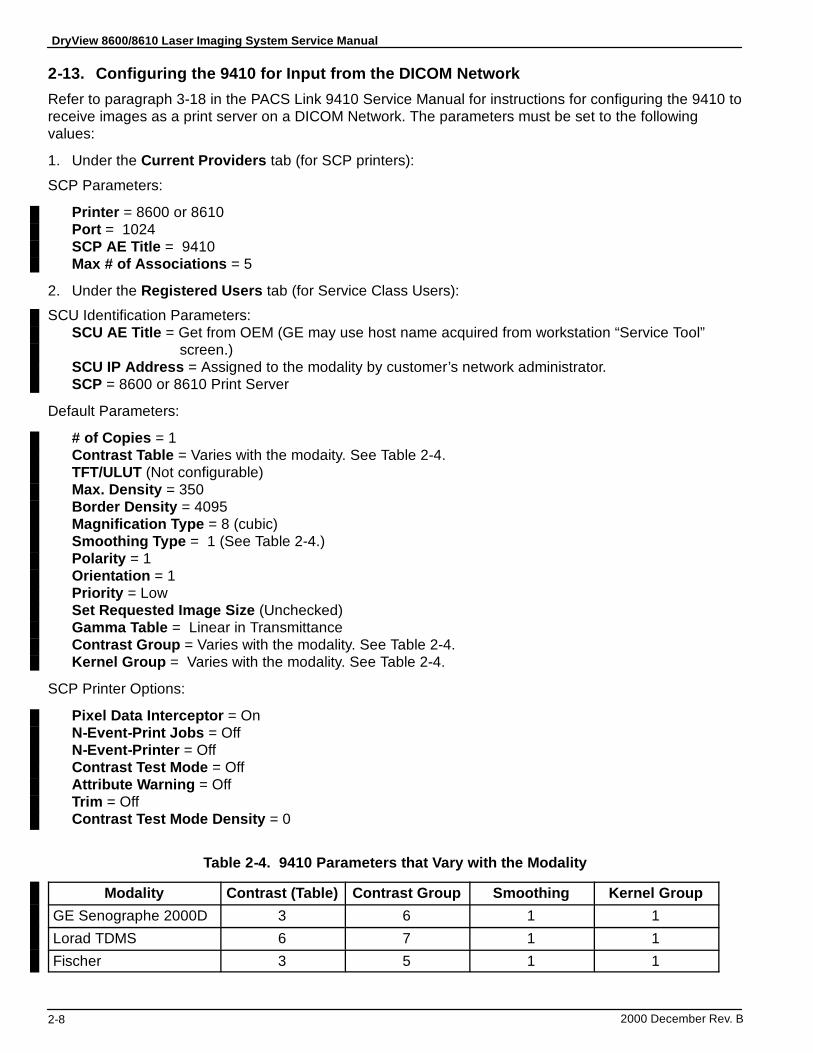
DryView 8600/8610 Laser Imaging System Service Manual
2000 December Rev. B2-8
2-13. Configuring the 9410 for Input from the DICOM Network
Refer to paragraph 3-18 in the PACS Link 9410 Service Manual for instructions for configuring the 9410 toreceive images as a print server on a DICOM Network. The parameters must be set to the followingvalues:
1. Under the Current Providers tab (for SCP printers):
SCP Parameters:
Printer = 8600 or 8610Port = 1024SCP AE Title = 9410Max # of Associations = 5
2. Under the Registered Users tab (for Service Class Users):
SCU Identification Parameters:SCU AE Title = Get from OEM (GE may use host name acquired from workstation “Service Tool”
screen.)SCU IP Address = Assigned to the modality by customer’s network administrator.SCP = 8600 or 8610 Print Server
Default Parameters:
# of Copies = 1Contrast Table = Varies with the modaity. See Table 2-4.TFT/ULUT (Not configurable)Max. Density = 350Border Density = 4095Magnification Type = 8 (cubic)Smoothing Type = 1 (See Table 2-4.)Polarity = 1Orientation = 1Priority = LowSet Requested Image Size (Unchecked)Gamma Table = Linear in TransmittanceContrast Group = Varies with the modality. See Table 2-4.Kernel Group = Varies with the modality. See Table 2-4.
SCP Printer Options:
Pixel Data Interceptor = OnN-Event-Print Jobs = OffN-Event-Printer = OffContrast Test Mode = OffAttribute Warning = OffTrim = OffContrast Test Mode Density = 0
Table 2-4. 9410 Parameters that Vary with the Modality
Modality Contrast (Table) Contrast Group Smoothing Kernel GroupGE Senographe 2000D 3 6 1 1Lorad TDMS 6 7 1 1Fischer 3 5 1 1
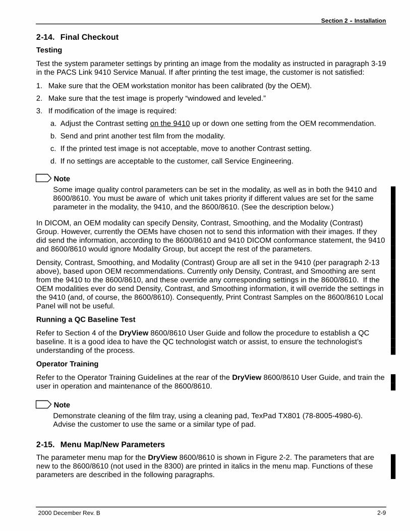
Section 2 -- Installation
2000 December Rev. B 2-9
2-14. Final Checkout
Testing
Test the system parameter settings by printing an image from the modality as instructed in paragraph 3-19in the PACS Link 9410 Service Manual. If after printing the test image, the customer is not satisfied:
1. Make sure that the OEM workstation monitor has been calibrated (by the OEM).
2. Make sure that the test image is properly “windowed and leveled.”
3. If modification of the image is required:
a. Adjust the Contrast setting on the 9410 up or down one setting from the OEM recommendation.
b. Send and print another test film from the modality.
c. If the printed test image is not acceptable, move to another Contrast setting.
d. If no settings are acceptable to the customer, call Service Engineering.
NoteSome image quality control parameters can be set in the modality, as well as in both the 9410 and8600/8610. You must be aware of which unit takes priority if different values are set for the sameparameter in the modality, the 9410, and the 8600/8610. (See the description below.)
In DICOM, an OEM modality can specify Density, Contrast, Smoothing, and the Modality (Contrast)Group. However, currently the OEMs have chosen not to send this information with their images. If theydid send the information, according to the 8600/8610 and 9410 DICOM conformance statement, the 9410and 8600/8610 would ignore Modality Group, but accept the rest of the parameters.
Density, Contrast, Smoothing, and Modality (Contrast) Group are all set in the 9410 (per paragraph 2-13above), based upon OEM recommendations. Currently only Density, Contrast, and Smoothing are sentfrom the 9410 to the 8600/8610, and these override any corresponding settings in the 8600/8610. If theOEM modalities ever do send Density, Contrast, and Smoothing information, it will override the settings inthe 9410 (and, of course, the 8600/8610). Consequently, Print Contrast Samples on the 8600/8610 LocalPanel will not be useful.
Running a QC Baseline Test
Refer to Section 4 of the DryView 8600/8610 User Guide and follow the procedure to establish a QCbaseline. It is a good idea to have the QC technologist watch or assist, to ensure the technologist’sunderstanding of the process.
Operator Training
Refer to the Operator Training Guidelines at the rear of the DryView 8600/8610 User Guide, and train theuser in operation and maintenance of the 8600/8610.
NoteDemonstrate cleaning of the film tray, using a cleaning pad, TexPad TX801 (78-8005-4980-6).Advise the customer to use the same or a similar type of pad.
2-15. Menu Map/New Parameters
The parameter menu map for the DryView 8600/8610 is shown in Figure 2-2. The parameters that arenew to the 8600/8610 (not used in the 8300) are printed in italics in the menu map. Functions of theseparameters are described in the following paragraphs.
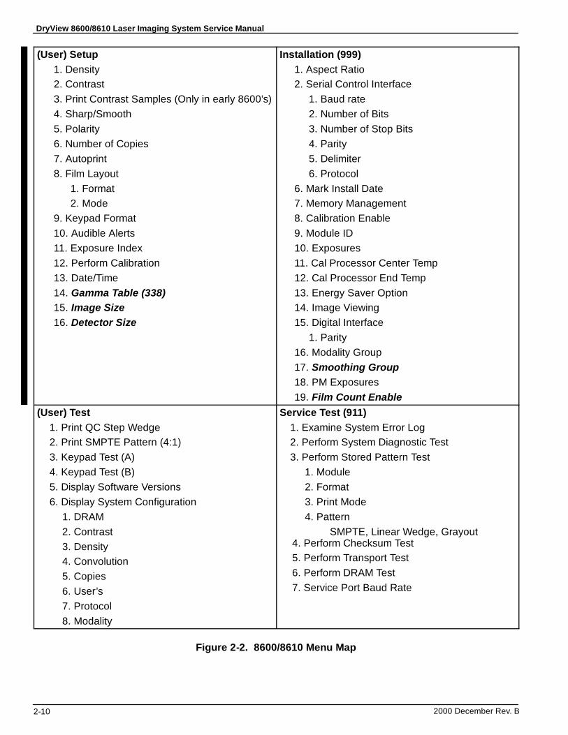
DryView 8600/8610 Laser Imaging System Service Manual
2000 December Rev. B2-10
(User) Setup1. Density2. Contrast3. Print Contrast Samples (Only in early 8600’s)4. Sharp/Smooth5. Polarity6. Number of Copies7. Autoprint8. Film Layout
1. Format2. Mode
9. Keypad Format10. Audible Alerts11. Exposure Index12. Perform Calibration13. Date/Time14. Gamma Table (338)15. Image Size16. Detector Size
Installation (999)1. Aspect Ratio2. Serial Control Interface
1. Baud rate2. Number of Bits3. Number of Stop Bits4. Parity5. Delimiter6. Protocol
6. Mark Install Date7. Memory Management8. Calibration Enable9. Module ID10. Exposures11. Cal Processor Center Temp12. Cal Processor End Temp13. Energy Saver Option14. Image Viewing15. Digital Interface
1. Parity16. Modality Group17. Smoothing Group18. PM Exposures19. Film Count Enable
(User) Test1. Print QC Step Wedge2. Print SMPTE Pattern (4:1)3. Keypad Test (A)4. Keypad Test (B)5. Display Software Versions6. Display System Configuration
1. DRAM2. Contrast3. Density4. Convolution5. Copies6. User’s7. Protocol8. Modality
Service Test (911)1. Examine System Error Log2. Perform System Diagnostic Test3. Perform Stored Pattern Test
1. Module2. Format3. Print Mode4. Pattern
SMPTE, Linear Wedge, Grayout4. Perform Checksum Test5. Perform Transport Test6. Perform DRAM Test7. Service Port Baud Rate
Figure 2-2. 8600/8610 Menu Map
Health Imaging
Technical Bulletin DryView 8600/8610
Eastman Kodak Company
1 Imation WayOakdale, MN 55128
Health Imaging Products
http://www.kodak.comPrinted in the U.S.A.© Kodak 2001 April
12-04/01 Artifacts and Scratches on Film
NoteThis Technical Bulletin is a revision and reissue of Technical Bulletin 10-01/01, Artifacts on Film.
Because of the desire of mammography customers to obtain artifact-free images, this Tech Bulletin provides trouble analysis procedures relating to artifacts that might appear on Kodak Dryview Mammography Laser Imaging Film used in Kodak DryView 8600 and 8610 LASER IMAGERS.
1. White Spot Line
ProblemWhite spots on the image, clumped together, approximately 3/8 inch (9 mm) apart, that appear to coincide with the spacing of the top separator assembly O-rings. The spots tend to be irregularly shaped and100-200 microns in size. The spot clumps form a line approximately 1-1/8 inch (2.8 cm), for the 8600, or7/8 inch (2.2 cm), for the 8610, from the leading edge of the film. The line can repeat itself (very lightly) down the film about every 2 inches (5.08 cm), which corresponds to a roller diameter of 5/8 inch (16 mm). The spots are most visible on higher density images, such as Dmax, although they can also be seen on lower density films.
CauseThe spots are actually unexposed areas of emulsion from a shadow of debris that blocks the laser beam during imaging. The debris is trailing-edge coating delamination that gets loosened by the separatorO-rings if they continue to drive after the separator clutches de-energize. The clutches de-energize when the leading edge of the film enters the capstan area and actuates the capstan media sense switch. When the clutches de-energize, the separator rollers are supposed to turn freely on the trailing edge of the film while it is pulled into the capstan area by the capstan pinch roller. If the separator rollers do not turn freely, theO-rings loosen trailing edge particles, which then are deposited onto the first capstan pinch roller when the trailing edge of the film reaches it. These particles then get transferred from the pinch roller onto the next sheet of film, about 1 inch (2.54 cm) from the top edge, when it enters the capstan area.
SolutionTo prevent the separator rollers from continuing to drive after the separator clutches are de-energized, order and install a spring-loaded separator assembly (8E2001).
NoteThe spring-loaded separator assembly and a modified scoop have been added to all 8610’s, serial number 86ED11090 and higher, so this artifact should not occur with these newer machines. Contact TAC if one of these imagers is still experiencing this artifact.
2. Fine Line, Repetitive Scratches
ProblemScratches on the film on the emulsion side, in the same direction as film travel, deep enough to be seen on a light box. Typically, the scratches are in the same location on each film and are repetitive from film to film. This type of scratching is different from the random fine-line scratching that occurs when the sheet of film rubs on the film below it as it is being fed from the film tray. (See Article 3 following for a discussion of random fine line scratches.)
CauseScratching is usually caused by small specks of debris that accumulate in the film path in specific areas. Common areas where this occurs are (1) the ramp edge of the film tray, (2) the entrance guide from the film tray to the separator rollers, and (3) the top edge of the scoop in the capstan area.
SolutionRemove the small specks of debris from the top three areas of accumulation indicated above.
1. The operator should clean the film tray (which includes the ramp edge) each time a new package of film is loaded, as outlined in the User Guides for the 8600 and 8610. After cleaning there sometimes is still a small burr on the ramp edge that needs to be polished off with fine lapping paper.
2. The entrance guide to the separator area in the 8610 is made of a Rigitex material, and has been designed to reduce scratching in this area. In any 8600 that exhibits scratching, the entrance guide (part number 6E8510) needs to be replaced. If the entrance guide has been updated and is still causing scratches, it may need to be polished with lapping paper to remove any buildup of debris.
3. The scoop, which provides a path for the film to move from the separator assembly to the capstan area, should also be composed of Rigitex. The top edge of the scoop, closest to the capstan pinch rollers, may also need to be polished with lapping paper. To gain access to the top edge, remove the capstan pinch rollers. Once the scoop is polished and the pinch rollers are back in place, print several films to verify that scratching has been eliminated.
3. Random Fine Line Scratches
ProblemFine line scratches on the emulsion side of the film, in the same direction as film travel, deep enough to be seen on a light box. Typically, the scratches are not in the same location on each film, and are relatively short in length, often less than 3 inches (75 mm). In many cases, they are more predominant on the bottom one third of the film.
CauseThis fine line scratching occurs when the sheet of film rubs on the film below it when it is being fed from the film tray.
SolutionThis is a system problem, and there is no comprehensive solution, since both the equipment and the film are responsible for the scratches. If a customer has lodged a complaint, prepare to send some example films with the offending scratches identified (marked). Call TAC to obtain the address to send the example film to, and for the next step in resolving the customer complaint.
4. “Milky Way”
ProblemThis artifact, called “Milky Way,” is a line of very fine white specks in the image, which is visible usually only with a minimum of 2X magnification. The specks are approximately 20 microns in size, and they form a line approximately 1/16 inch (1.6 mm) in width, located approximately 1-1/8 inch (2.8 cm), for the 8600, or 7/8 inch (2.2 cm), for the 8610, from the leading edge of the film. The line is called “Milky Way” because the specks resemble a cluster of stars in a dark sky. The line of specks may or may not appear across the entire width of the film, and are most visible in lower density image areas, but may also be seen in Dmax areas.
CauseThe specks are shadow artifacts of unexposed areas of emulsion where debris has blocked the laser beam during imaging. The debris appears to be small particles that accumulate on the trailing edge of the film, and then get deposited onto the first capstan pinch roller when the trailing edge is released by the roller. The particles then transfer from the pinch roller onto the next sheet of film, about 1 inch (2.54 cm) from the top edge, when it enters the capstan area.
SolutionThere is no comprehensive solution, since it is not perfectly clear why the particles accumulate on the film’s trailing edge. If a customer has complained, prepare to send some example films with the offending artifacts identified (marked). Call TAC to obtain the address to send the example films to, and for the next step in resolving the customer complaint.
5. Thin Band, 5-1/2 Inches from the Top of the Film
ProblemA thin lower density band or line, across the entire width of the film, located 5-1/2 inches (13.8 cm) from the top.
CauseThe band is caused by a hesitation while the film is being imaged. Either the upper wire film guide is not properly snapped into place, or the processor entrance guides are bowed, or the processor assembly is not seated squarely on the machine frame on which it rests.
Solution
1. Advise the operator to be sure that both sides of the upper wire film guide are snapped back into place if the film guide is ever moved (for example, if it had to be released to remove a film jam).
2. Check the processor entrance guide plates to make sure they are not bowed. Bowing can occur if the mounting screws and nuts have been overtightened during assembly.
3. Make sure that the processor assembly is seated properly, and that the upper wire film guide is snapped into place.
6. Vertical Streaks Down the Length of the Film (Processor Related)
ProblemThin (1 to 5 mm) vertical streaks down the entire length of the film. To confirm that the streaks are not optics-related, remove a sheet of film from the film tray and expose it to ambient light for only about 2-3 seconds. Then reinsert it into the film tray. Run the transport test, which sends film through the imager with the optics module deactivated. If the streaks appear on the processed film, they are processor (drum) related.
CauseThe streaks are actually a difference in density from the rest of the image, caused by a scored drum surface. The drum gets scored when small deposits of faz accumulate on the under side of the stripper assembly. This sometimes is the result of the operator powering the imager off at night, which allows the faz to cool and harden.
Solution
Replace the drum if its scored surface is causing the streaks. To prevent such streaks from occurring again, clean the underside of the stripper assembly when you are doing a PM. In addition, advise the operator that it is recommended that the power to the imager be left on 24 hours a day.
7. Vertical Streaks Down the Length of the Film (Optics Related)
ProblemWide vertical streaks down the film that are most obvious on the mid-tone bands of the film calibration sheet. The streaks are generally near the center third of the film. To confirm that the streaks are optics-related, remove a sheet of film from the film tray and expose it to ambient light for only about 2-3 seconds. Then reinsert it into the film tray. Run the transport test, which sends film through the imager with the optics module deactivated. If the streaks still appear on the processed film, they are processor (drum) related, not optics related. (In this case, see the preceding paragraph.)
CauseDust off the final deflection mirror in the optics module.
SolutionRemove the optics module and use canned air to blow the dust off the deflection mirror, as viewed through the aperture. Make sure to hold the can upright and sweep across the mirror with smooth but definite motion. If you do not use this technique, the air may sputter, causing liquid spots on the mirror. Reinstall the optics module and run several films to verify that the mirror is now clean.
8. Mini Moire
ProblemThe artifact called “Mini-Moire” is a very subtle pattern across the width of the film that appears as swirled pixels. Its thickness can range from a few scan lines up to an inch (2.54 cm) in height.
CauseThis artifact is the result of a stability problem in the optics module galvanometer.
Solution
Replace the optics module.
Service & SupportHealth Imaging
Kodak DryView 8600/8610 LASER IMAGING SYSTEMS
Technical Bulletin July 2001
Eastman Kodak Company
1 Imation WayOakdale, MN 55128
Health Imaging Products
http://www.kodak.comPrinted in the U.S.A.
© Kodak 2001 July
14-07/01 EC27 or EC28 - Film Stopping in Processor
This is a reissue of Technical Bulletin 13-04/01, EC27 or EC28 - Film Stopping in Processor.
ProblemFILM moves through the processor too slowly and the SOFTWARE times out, producing an Error Code 27 or Error Code 28.
CauseFILM did not get a positive start into the PROCESSOR. Possible causes include:
1. Bowed ENTRANCE GUIDES caused by over-tightening of the MOUNTING HARDWARE during production. The bow causes a high resistance in the FILM path. (See Solution 1.)
2. Metal ENTRANCE or EXIT ROLLER is broken loose from the SHAFT. (See Solution 2.)
3. RUBBER ENTRANCE or EXIT PINCH ROLLERS are coated or hardened and can no longer capture the leading edge of the FILM. (See Solution 3.)
4. The ends of the SHAFT of the RUBBER ENTRANCE and EXIT PINCH ROLLERS are contaminated and no longer rotate freely in their BUSHINGS. (See Solution 4.)
Solution1. Remove the PROCESSOR ASSEMBLY and loosen the SCREWS and/or NUTS that hold the
ENTRANCE GUIDES (located on the under side). Check that the GUIDES are no longer bowed. Then tighten the HARDWARE to keep the GUIDES from bowing.
2. Remove the Metal ENTRANCE or EXIT ROLLERs and check that each DRIVE SIDE SHAFT is correctly held in place on the ROLLER. If not, remove the SHAFT, place a small drop of EPOXY GLUE in the ROLLER and slowly press the SHAFT back into the ROLLER. If you cannot install the SHAFT, install a new ENTRANCE ROLLER (78-8100-0293-7) or EXIT ROLLER (78-8100-0431-3), as necessary.
3. Clean both RUBBER ROLLERS with ALCOHOL. If the surface is not soft after cleaning, install a new ROLLER (78-8113-2104-7).
4. Remove the ROLLERS from their BUSHINGS in the PROCESSOR and clean the ends of the SHAFTS with a SCOURING PAD or STEEL WOOL until they are smooth. Clean the insides of the BUSHINGS to remove any contamination. Check that the BUSHINGS rotate freely on the ends of the SHAFTS before installing in the PROCESSOR ASSEMBLY. If the BUSHINGS are badly scored or still do not rotate freely, install new BUSHINGS (8E2021, set of 2).
Service & SupportHealth Imaging
Kodak DryView 8600/8610 LASER IMAGERS
Technical Bulletin September 2001
Eastman Kodak Company
1 Imation WayOakdale, MN 55128
Health Imaging Products
http://www.kodak.comPrinted in the U.S.A.
© Kodak 2001
15-09/01 Milky Way Artifacts
ProblemThe artifact known as “Milky Way” prints as a line of fine, white specks on the image, normally only visible with a minimum of 2X magnification.
The size of the specks is about 20 microns and they form a line about 1/16 in. thick. Distance from the leading edge is about:
• 1 1/8 in. for Kodak DryView 8600 LASER IMAGERS
• 7/8 in. for Kodak DryView 8610 LASER IMAGERS
The artifact is called “Milky Way” because it resembles a cluster of stars in a dark sky. The line of specks might or might not cover the width of the film. The specks are most visible in low-density image areas but might also be visible in D-max areas.
The Milky Way artifact is similar to the “White Spot Line” artifact, but is not the same. The spots caused by the “White Spot Line” artifact are 100-200 microns in size and are visible without any magnification.
CauseThe specks are shadow artifacts of unexposed areas of emulsion caused when debris blocks the laser beam during imaging. As small particles of debris accumulate on the trailing edge of the film, they are deposited on the first CAPSTAN PINCH ROLLER when the ROLLER releases the trailing edge of the film. These particles are then transferred from the CAPSTAN PINCH ROLLER to the next sheet of film (about 1 in. from the top edge) when it enters the area of the CAPSTAN.
SolutionInstall a new CAPSTAN PINCH ROLLER ASSEMBLY 8E2016 that has ROLLERS with smooth surfaces that do not accumulate debris.
Service & SupportHealth Imaging
Kodak DryView 8600/8610 LASER IMAGERS
Technical Bulletin September 2001
Eastman Kodak Company
1 Imation WayOakdale, MN 55128
Health Imaging Products
http://www.kodak.comPrinted in the U.S.A.
© Kodak 2001
16-09/01 Film Scratches
Scratches Visible in Reflected Light
Problem
Scratches on the emulsion side of the film that are visible with reflected light. The scratches are normally located in the same position on each sheet and occur in the same direction that the film moves.
Cause
This scratching occurs when the soft emulsion of the processed sheet of film moves over contamination on the FELT PAD or only the metal part of the STRIPPER, or a dirty DENSITOMETER.
Solution
Clean the STRIPPER and DENSITOMETER and remove any FELT PADS that have any FAZ or other hardened contaminants and install new FELT PADS. You might have to install a new STRIPPER if the old one cannot be cleaned.
Some small surface scratches will still be visible under reflected light because they are inherent in this IMAGER. Advise the customer that this type of scratch is not visible with transmitted light and will not affect their reading.
Random Fine Line Scratches Visible in Transmitted Light
Problem
Random line scratches on the emulsion side of the film are visible with transmitted light from a light box or “hot light.” The scratches occur in the same direction that the film moves. Normally, these scratches are most visible when viewed directly, but are not normally visible when viewed left or right of center.
Cause
Fine line scratches occur when a sheet of film rubs on the sheet under it as the film is fed from the FILM TRAY.
Solution
Fine line scratches visible with transmitted light is a SYSTEM problem because both the IMAGER and the film cause the scratches. Changing to another lot of film might reduce the occurrences. Advise the customer that this type of scratching is random and we are working on a solution.
Service & SupportHealth Imaging
Kodak DryView 8600 and 8610 LASER IMAGERS
Technical Bulletin September 2001
Eastman Kodak Company
1 Imation WayOakdale, MN 55128
Health Imaging Products
http://www.kodak.comPrinted in the U.S.A.
© Kodak 2001
17-09/01 Light Density Streaks on Film
ProblemLight streaks appear down the film, usually around the middle, and most are visible in the mid-tone grays of the images.
CauseDust has collected on the final MIRROR that directs the laser beam to the film.
Solution1. Print an image to be used for comparison. A film calibration sheet might show the artifact.
2. Remove the OPTICS MODULE from the imager and set it on a TABLE in the same position as when it is in the imager.
3. Insert the NOZZLE from the CANISTER in the OPTICS MODULE CLEANING KIT 74-0401-82380-3 into the laser-beam aperture slot toward the top of the OPTICS MODULE.
4. Holding the CANISTER upright, spray short bursts while moving the NOZZLE back and forth along the aperture slot.
NoteDo not touch the MIRROR with the NOZZLE and do not tilt, invert or shake the CANISTER while spraying air into the opening.
5. Remove the NOZZLE and replace the OPTICS MODULE into the imager.
6. Run a comparison image to check that the light streak has been removed.
Service & SupportHealth Imaging
Kodak DryView 8600/8610 LASER IMAGERS
Technical Bulletin October 2001
Eastman Kodak Company
1 Imation WayOakdale, MN 55128
Health Imaging Products
http://www.kodak.comPrinted in the U.S.A.
© Kodak 2001
19-10/01 Scan Lines/Grid Lines Visible in the IMAGER
Problem
The customer has identified an intermittent pattern on the FILM that appears under magnification and resembles “scan lines” or “grid lines.” The lines are spaced at about 4-6 per mm and are most visible in the mid-tone gray areas of test images with flat-field areas. These lines result from density variations and are caused by small, intermittent placement errors of the actual scan lines. The eye sees these as “scan lines” or “grid lines.”
Cause
A vibration transmitted to the OPTICS MODULE causes the intermittent scan lines as the laser beam images the FILM. A vibration in the bearings of the FAZ FILTER FAN is the most frequent cause. To verify this, temporarily disconnect the power to the FAZ FILTER FAN.
Solution
If disconnecting the power or replacing the FAZ FILTER FAN does not decrease the artifact to a level acceptable by the customer, you might have to install a new OPTICS MODULE. Call the Technical Assistance Center at 1-800-328-2910, silent prompt 9 for permission to order a new OPTICS MODULE.
Service & SupportHealth Imaging
Kodak DryView 8600/8610 LASER IMAGERS
Technical Bulletin October 2001
Eastman Kodak Company
1 Imation WayOakdale, MN 55128
Health Imaging Products
http://www.kodak.comPrinted in the U.S.A.
© Kodak 2001
20-10/01 Large Side Border from General Electric SENOGRAPHE ACQUISITION WORKSTATION
Problem
Images that are acquired from the General Electric SENOGRAPHE 2000D FFDM ACQUISITION WORKSTATION are printed smaller than the images printed from the General Electric REVIEW WORKSTATION. This results in a larger border on one side of the image.
Cause
General Electric adds patient information to the bottom of the images that are printed from the ACQUISITION WORKSTATION. This patient information is not included on images printed from the REVIEW WORKSTATION.
The patient information results in a shorter image height and to keep the correct aspect ratio, the image width is also cut down. The smaller width increases the border on one side of the image.
Solution
Inform the customer that this is a function of the ACQUISITION WORKSTATION and that images printed from the REVIEW WORKSTATION will be true size, but images printed from the ACQUISITION WORKSTATION will not.
Service & SupportHealth Imaging
Kodak DryView 8600/8610 LASER IMAGERS
Technical Bulletin October 2001
Eastman Kodak Company
1 Imation WayOakdale, MN 55128
Health Imaging Products
http://www.kodak.comPrinted in the U.S.A.
© Kodak 2001
21-10/01 Abrupt Density Changes or Course Scan Lines
Problem
The 8610 LASER IMAGER produces images with abrupt density changes, or horizontal bands that appear as if some scan lines are missing.
Cause
The MOTOR CONTROL BOARD is causing the CAPSTAN MOTOR to operate erratically.
Solution
Replace the MOTOR CONTROL BOARD.
Service & SupportHealth Imaging
Kodak DryView 8600/8610 LASER IMAGERS
Technical Bulletin December 2001
Eastman Kodak Company
1 Imation WayOakdale, MN 55128
Health Imaging Products
http://www.kodak.comPrinted in the U.S.A.
© Kodak 2001
22-12/01 Scan Lines/Grid Lines Visible in the IMAGER - Reissue
Problem
The customer has identified an intermittent pattern on the FILM that appears under magnification and resembles “scan lines” or “grid lines.” The lines are spaced at about 4-6 per mm and are most visible in the mid-tone gray areas of test images with flat-field areas. These lines result from density variations and are caused by small, intermittent placement errors of the actual scan lines. The eye sees these as “scan lines” or “grid lines.”
Cause
A vibration transmitted to the OPTICS MODULE causes the intermittent scan lines as the laser beam images the FILM. A vibration in the bearings of the FAZ FILTER FAN is the most frequent cause. To verify this, temporarily disconnect the power to the FAZ FILTER FAN.
Solution
Install the new FAZ FILTER FAN 8E2050 made for the 8600/8610 LASER IMAGERS. If replacing the FAZ FILTER FAN does not decrease the artifact, you might have to install a new OPTICS MODULE. Call the Technical Assistance Center at 1-800-328-2910, silent prompt 9 for permission to order a new OPTICS MODULE.
Service & SupportHealth Imaging
Kodak DryView 8600 and 8610 LASER IMAGERS
Technical Bulletin December 2001
Eastman Kodak Company
1 Imation WayOakdale, MN 55128
Health Imaging Products
http://www.kodak.comPrinted in the U.S.A.
© Kodak 2001
23-12/01 Operator Training Materials
A TRAINING MANUAL is now being sent with all Kodak DryView 8610 LASER IMAGERS. The MANUAL is provided as a help tool for the FE to use when doing operator training.
The TRAINING MANUAL includes:
• a 3-ring binder with laminated slides that can be used as a flip chart.
• 5 sets of SLIDES for the training participants.
• an INSTRUCTOR GUIDE with a SCRIPT.
24-12/01 Network Connection Inputs
The Kodak DryView 8610 LASER IMAGER allows only 1 Digital Host Control (copper) input from the Kodak PACS LINK 9410 ACQUISITION SYSTEM.
The Kodak DryView 8610 LASER IMAGER allows only 1 DICOM network connection input to the Kodak PACS LINK 9410 ACQUISITION SYSTEM. If a customer wants a second MODALITY to make a print on the 8610 LASER IMAGER, the MODALITY must be a Registered User and send its images through the network connection. If the second MODALITY is not DICOM-compatible, a second 9410 ACQUISITION SYSTEM must be added as a MODALITY SERVER. This MODALITY SERVER will convert the output of the MODALITY to a usable DICOM format to be sent to the 8610 LASER IMAGER/ 9410 ACQUISITION SYSTEM.
Printed in U.S.A. • 23_24_ 25_TrngMat_SysInputs_FeedFilm.fm
EASTMAN KODAK COMPANYRochester, NY 14650 HEALTH IMAGING
25-12/01 FILM TRAY will not Feed Film
Problem
Continual EC 33 error codes occur, or the new light-weight FILM FEED ROLLER cannot feed the last sheets of film in the FILM TRAY.
Cause
When the film is at a low level, the density of the FOAM used for registration in the FILM TRAY causes pressure on the film.
Solution
Replace the FILM TRAY 78-8096-3201-7. All of the FILM TRAYS stocked in Service Parts have FOAM with a lighter density. The new FILM TRAYS can be identified by the ½-in. Kodak logo on the outside bottom of the TRAY.
Kodak and DryView are trademarks.
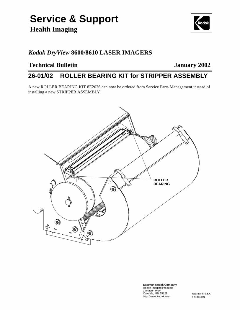
Service & SupportHealth Imaging
Kodak DryView 8600/8610 LASER IMAGERS
Technical Bulletin January 2002
Eastman Kodak Company
1 Imation WayOakdale, MN 55128
Health Imaging Products
http://www.kodak.comPrinted in the U.S.A.
© Kodak 2002
26-01/02 ROLLER BEARING KIT for STRIPPER ASSEMBLY
A new ROLLER BEARING KIT 8E2026 can now be ordered from Service Parts Management instead of installing a new STRIPPER ASSEMBLY.
ROLLERBEARING
Service & SupportHealth Imaging
Kodak DryView 8600/8610 LASER IMAGERS
Technical Bulletin January 2002
Eastman Kodak Company
1 Imation WayOakdale, MN 55128
Health Imaging Products
http://www.kodak.comPrinted in the U.S.A.
© Kodak 2002
27-01/02 Purple/Green Reflections on Film
Problem
When the surface of the “antihalation” side of the film is viewed in reflected fluorescent light, purple/green streaks or wavy colored areas are visible. When the film is viewed in only reflected “incandescent” light, the colors are not visible.
Cause
Fluorescent TUBES have high quantities of energy in narrow-wavelength bands in the purple/green area of the visible spectrum. When this light is viewed reflected from the “antihalation” side of the film, the coherency of these narrow-wavelength bands is enough to cause interference effects in the thin layer on the “antihalation” side of the film. The effect is a contour map of the thin film thickness in the “antihalation coating” where the interference occurs.
When this light is viewed reflected from the “antihalation” side of the film, the coherency of these narrow-wavelength bands is enough to cause interference effects (i.e., a contour map) in the thin-film layer on the “antihalation” side of the film.
Solution
When the radiologists view the films on a normal light box during transmission, the purple/green variations or density variations will have no affect on the film reading.
There can be large variations between film lots. Customers who see a large number of variations can order new film to minimize their concern.
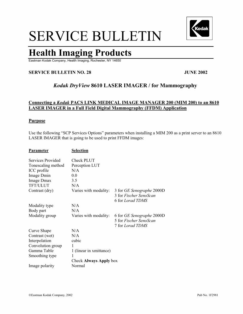
SERVICE BULLETINHealth Imaging ProductsEastman Kodak Company, Health Imaging, Rochester, NY 14650
�Eastman Kodak Company, 2002 Pub No. 1F2981
SERVICE BULLETIN NO. 28 JUNE 2002
Kodak DryView 8610 LASER IMAGER / for Mammography
Connecting a Kodak PACS LINK MEDICAL IMAGE MANAGER 200 (MIM 200) to an 8610LASER IMAGER in a Full Field Digital Mammography (FFDM) Application
Purpose
Use the following “SCP Services Options” parameters when installing a MIM 200 as a print server to an 8610LASER IMAGER that is going to be used to print FFDM images:
Parameter Selection
Services Provided Check PLUTTonescaling method Perception LUTICC profile N/AImage Dmin 0.0Image Dmax 3.5TFT/ULUT N/AContrast (dry) Varies with modality: 3 for GE Senographe 2000D
3 for Fischer SenoScan6 for Lorad TDMS
Modality type N/ABody part N/AModality group Varies with modality: 6 for GE Senographe 2000D
5 for Fischer SenoScan7 for Lorad TDMS
Curve Shape N/AContrast (wet) N/AInterpolation cubicConvolution group 1Gamma Table 1 (linear in xmittance)Smoothing type 1
Check Always Apply boxImage polarity Normal
Printed in the USA. Pub No. 1F2981
©Eastman Kodak CompanyRochester, NY 14650
HEALTH IMAGING
Gary Ketch, Service Engineer-OakdaleFor more information please contact:
Eastman Kodak CompanyHealth Imaging – TSC6200 Tennyson ParkwayPlano, TX 75024, USA(800) 544-7009
Kodak and DryView are trademarks.
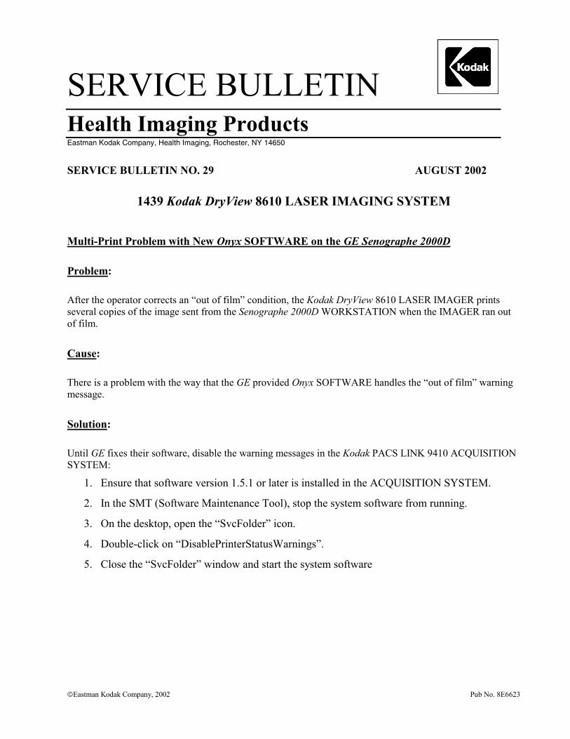
SERVICE BULLETIN Health Imaging Products
Eastman Kodak Company, Health Imaging, Rochester, NY 14650
�Eastman Kodak Company, 2002 Pub No. 8E6623
SERVICE BULLETIN NO. 29 AUGUST 2002
1439 Kodak DryView 8610 LASER IMAGING SYSTEM
Multi-Print Problem with New Onyx SOFTWARE on the GE Senographe 2000D
Problem:
After the operator corrects an “out of film” condition, the Kodak DryView 8610 LASER IMAGER prints several copies of the image sent from the Senographe 2000D WORKSTATION when the IMAGER ran out of film.
Cause:
There is a problem with the way that the GE provided Onyx SOFTWARE handles the “out of film” warning message.
Solution:
Until GE fixes their software, disable the warning messages in the Kodak PACS LINK 9410 ACQUISITION SYSTEM:
1. Ensure that software version 1.5.1 or later is installed in the ACQUISITION SYSTEM.
2. In the SMT (Software Maintenance Tool), stop the system software from running.
3. On the desktop, open the “SvcFolder” icon.
4. Double-click on “DisablePrinterStatusWarnings”.
5. Close the “SvcFolder” window and start the system software

Printed in the USA. Pub No. 8E6623 ©Eastman Kodak Company Rochester, NY 14650 HEALTH IMAGING
Gary Ketch, Service Engineer-Oakdale For more information please contact:
Eastman Kodak Company Health Imaging 1 Imation Way Discovery Building 3B-61 Oakdale, MN 55128-3414, USA 1-800-328-2910
Kodak and DryView are trademarks.
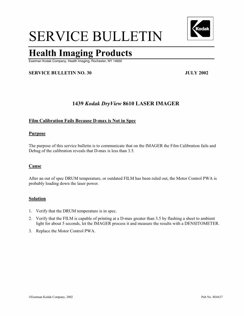
SERVICE BULLETIN Health Imaging Products
Eastman Kodak Company, Health Imaging, Rochester, NY 14650
�Eastman Kodak Company, 2002 Pub No. 8E6637
SERVICE BULLETIN NO. 30 JULY 2002
1439 Kodak DryView 8610 LASER IMAGER
Film Calibration Fails Because D-max is Not in Spec
Purpose
The purpose of this service bulletin is to communicate that on the IMAGER the Film Calibration fails and Debug of the calibration reveals that D-max is less than 3.5.
Cause
After an out of spec DRUM temperature, or outdated FILM has been ruled out, the Motor Control PWA is probably loading down the laser power.
Solution
1. Verify that the DRUM temperature is in spec.
2. Verify that the FILM is capable of printing at a D-max greater than 3.5 by flashing a sheet to ambient light for about 5 seconds, let the IMAGER process it and measure the results with a DENSITOMETER.
3. Replace the Motor Control PWA.

Printed in the USA. Pub No. 8E6637 ©Eastman Kodak Company, 2002 Rochester, NY 14650 HEALTH IMAGING
Gary Ketch, Service Engineer-Oakdale For more information please contact:
Eastman Kodak Company Health Imaging 1 Imation Way Discovery Building 3B-61 Oakdale, MN 55128-3414, USA 1-800-328-2910
Kodak and DryView are trademarks.
SERVICE BULLETIN Health Imaging Products
Eastman Kodak Company, Health Imaging, Rochester, NY 14650
�Eastman Kodak Company, 2002 Pub No. 8E6670
SERVICE BULLETIN NO. 31 AUGUST 2002
1437 and 1439 Kodak DryView 8600/8610 LASER IMAGERS
EC27 or EC28 – Film Stopping in PROCESSOR
Purpose
The purpose of this service bulletin is to communicate how to correct a problem that is caused when the film moves too slowly through the PROCESSOR.
Problem
The film moves through the PROCESSOR too slowly and the system software times out, producing an Error Code 27 or Error Code 28.
Cause
The film did not start correctly into the PROCESSOR because the metal entrance DRIVE ROLLER is too smooth and does not positively “grab” the film.
Solution
Remove the metal entrance DRIVE ROLLER from the PROCESSOR assembly. Hold the ROLLER firmly in one hand, and wrap a piece of 7447 (very fine) 3M Scotch-Brite PAD (TL5635) partially around the ROLLER with the other hand. While turning, pushing and pulling the ROLLER with one hand, hold the PAD against the ROLLER and turn and twist with the other hand. The expected result is that the PAD will create a very subtle dull, cross-hatched pattern on the ROLLER that will make it rough enough to properly grab the film. As an alternative, a factory rough DRIVE ROLLER (8E2075) is available from Service Parts.
When replacing the ROLLER into the PROCESSOR, be sure to position the SPACER WASHERS so that their smooth edge faces the BUSHINGS that hold the ROLLER in position.
After replacing the ROLLER if there is still a problem with film stopping in the PROCESSOR, refer to Technical Bulletin 11-08/01.

Printed in the USA. Pub No. 8E6670 ©Eastman Kodak Company, 2002 Rochester, NY 14650 HEALTH IMAGING
Gary Ketch, Service Engineer-Oakdale For more information please contact:
Eastman Kodak Company Health Imaging 1 Imation Way Discovery Building 3B-62 Oakdale, MN 55128-3414, USA 1-800-328-2910
Kodak and DryView are trademarks.
SERVICE BULLETIN Health Imaging Products
Eastman Kodak Company, Health Imaging, Rochester, NY 14650
©Eastman Kodak Company, 2002 Pub No. 8E6694
SERVICE BULLETIN NO. 32 SEPTEMBER 2002
1437 and 1439 Kodak DryView 8600/8610 LASER IMAGING SYSTEM
Cost Savings for Replacing PRESSURE ROLLERS
Purpose
The purpose of this service bulletin is to identify the cost savings possible when it is necessary to replace the following parts in the PROCESSOR ASSEMBLY 78-8113-2151-8.
Part Number Description 78-8113-2150-0 DEVELOPER DRUM ASSEMBLY, Gray 78-8113-2102-1 PRESSURE (3) ROLLER ASSEMBLY, Base 78-8113-2103-9 PRESSURE (9) ROLLER ASSEMBLY, Cover
Problem Description
If a PRESSURE ROLLER in either ROLLER ASSEMBLY stops rotating, the ROLLER surface could deplate or flatten in areas. When this occurs, aluminum deposits could cover the DRUM and change the DRUM color to black.
Problem Correction
If the ROLLERS are damaged, install a new ROLLER ASSEMBLY and clean the DRUM. If the DRUM is also damaged, install a new DRUM. Do not install a new PROCESSOR ASSEMBLY to correct these problems.
Cost Savings
Replacing only the damaged ROLLER ASSEMBLIES and DRUM, in place of installing a new PROCESSOR ASSEMBLY, will result in the following cost savings for Kodak.
Printed in the USA. Pub No. 8E6694 ©Eastman Kodak Company Rochester, NY 14650
HEALTH IMAGING
• Installing only a PRESSURE (9) ROLLER ASSEMBLY (Cover) and a PRESSURE (3) ROLLER ASSEMBLY (Base) will provide a savings of $2506.00 over replacing the entire PROCESSOR ASSEMBLY.
• Installing a DRUM in addition to the PRESSURE (9) ROLLER ASSEMBLY (Cover) and a PRESSURE (3) ROLLER ASSEMBLY (Base) will provide a savings of $1651.00 over replacing the entire PROCESSOR ASSEMBLY.
Gary Ketch, Service Engineer-Oakdale For more information please contact:
Eastman Kodak Company Health Imaging 1 Imation Way Discovery Building 3B-62 Oakdale, MN 55128-3414, USA 1-800-328-2910
Kodak and DryView are trademarks.
SERVICE BULLETIN Health Imaging Products
Eastman Kodak Company, Health Imaging, Rochester, NY 14650
�Eastman Kodak Company, 2002 Pub No. 8E6697
SERVICE BULLETIN NO. 33 AUGUST 2002
1437 and 1439 Kodak DryView 8600/8610 LASER IMAGING SYSTEM
Instructions for Grounding the PROCESSOR ASSEMBLY to Eliminate EC88s
Purpose
The purpose of this service bulletin is to provide instructions for grounding the PROCESSOR ASSEMBLY using the PROCESSOR GROUNDING HARDWARE KIT, 8E2003.
Procedure
1. Remove the SPRING CLIPS from the FRAME and CLAMSHELL of the PROCESSOR ASSEMBLY (see Fig. 1).
2. Attach one end of the WIRE (supplied in the KIT) to the STRIPPER ASSEMBLY using the right mounting SCREW of the STRIPPER ASSEMBLY (see Fig. 2).
3. Attach one end of 1 small STRAP (supplied in the KIT) along with the loose end of the WIRE referred to in Step 2, to the FRAME where the CLIP was removed in Step 1 (see Fig. 2).
4. Remove the SCREW holding the ROLLER ASSEMBLY MOUNTING ROD, and using the supplied SPACER and SCREW, attach the loose end of the small STRAP to the ROLLER ASSEMBLY MOUNTING ROD (see Fig. 2).
5. Repeat Steps 3 and 4 to attach the remaining small STRAP to either side of the CLAMSHELL portion of the PROCESSOR ASSEMBLY.
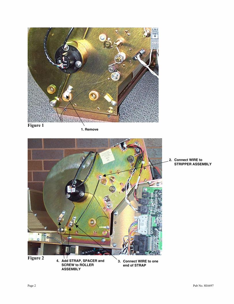
Page 2 Pub No. 8E6697
Figure 1
Figure 2
1. Remove
2. Connect WIRE to STRIPPER ASSEMBLY
3. Connect WIRE to one end of STRAP
4. Add STRAP, SPACER and SCREW to ROLLER ASSEMBLY

Pub No. 8E6697 Page 3
Gary Ketch, Service Engineer-Oakdale For more information please contact:
Eastman Kodak Company Health Imaging 1 Imation Way Discovery Building 3B-62 Oakdale, MN 55128-3414, USA 1-800-328-2910

Printed in the USA. Pub No. 8E6697 ©Eastman Kodak Company Rochester, NY 14650 HEALTH IMAGING
Kodak and DryView are trademarks.
SERVICE BULLETIN Health Imaging Products
Eastman Kodak Company, Health Imaging, Rochester, NY 14650
�Eastman Kodak Company, 2002 Pub No. 8E6797
SERVICE BULLETIN NO. 34 SEPTEMBER 2002
1437 and 1439 Kodak DryView 8600/8610 LASER IMAGER
Responding to Concerns About Subtle Artifacts
Purpose
The purpose of this service bulletin is to communicate how to respond to customers who may have questions about subtle artifacts that may occur on films printed with either of these IMAGERS. While the following information should not be given directly to the customer, it should be used to help the FE understand that the position of Kodak agrees with guidelines established by the American College of Radiology (ACR).
Response
The QC tests and procedures for full field digital mammography hardcopy films are not defined by ACR or Mammography Quality Standards Act (MQSA) at this time. The FDA’s position is to follow recommendations of Kodak until a formal process is in place. The most appropriate procedure is to follow the one for analog mammography films as outlined in the ACR Mammography Quality Control Manual. On page 255 the ALARA (as low as reasonably achievable) concept is described: “Not all artifacts can be totally eliminated. It may be helpful to use the concept of ALARA when attacking artifacts. If they can be easily eliminated, they should be. If the artifact is difficult or expensive to eliminate and it is subtle (not mimicking or obscuring clinical information), it may be tolerable. The medical physicist should consult with the interpreting physician as to whether the artifact is tolerable.” A flat-field gray-out test pattern is the most demanding type of test pattern for viewing certain types of artifacts. Artifacts, such as a low level of “banding”, which is a repeated small density variation down the ten-inch direction of the film, are typically evident in gray-outs produced by the IMAGER, and they normally meet our manufacturing release tolerances.
Printed in the USA. Pub No. 8E6797 ©Eastman Kodak Company Rochester, NY 14650 HEALTH IMAGING
The IMAGER was designed for use with full field digital mammography units. Kodak worked with GE and other major OEMs during the design of the IMAGER and the subsequent approval by the FDA for full field digital mammography applications. Based on our experience, we believe that typical IMAGER low-level artifacts will not mimic or obscure clinical information. Gary Ketch, Service Engineer-Oakdale For more information please contact:
Eastman Kodak Company Health Imaging 1 Imation Way Discovery Building 3B-62 Oakdale, MN 55128-3414, USA 1-800-328-2910
Kodak and DryView are trademarks of Eastman Kodak Company.
SERVICE BULLETIN Health Imaging Products
Eastman Kodak Company, Health Imaging, Rochester, NY 14650
�Eastman Kodak Company, 2002 Pub No. 8E6812
SERVICE BULLETIN NO. 35 SEPTEMBER 2002
1437 and 1439 Kodak DryView 8600/8610 LASER IMAGER
SCRATCH REDUCTION TOOL Available
Purpose
The purpose of this service bulletin is to provide information about a new tool that can be used to reduce repetitive scratching caused by particles or nicks on the FILM GUIDE SCOOP.
Procedure
To assist in the removal of repetitive scratches caused by particles or nicks on the lower FILM GUIDE SCOOP order the CROCUS CLOTH KIT 8E2083.
The CROCUS CLOTH is inserted manually onto the SCOOP, in the same manner as a piece of film would travel on the scoop. It is then rubbed against the entire length of the SCOOP so that it reaches the top edge, near the CASTAN ROLLER.
Once the polishing process is complete, clean the SCOOP thoroughly with an ALCOHOL WIPE such as a TX-1065 to remove any particles that were dislodged by the CROCUS CLOTH.
Printed in the USA. Pub No. 8E6812 ©Eastman Kodak Company Rochester, NY 14650 HEALTH IMAGING
Gary Ketch, Service Engineer-Oakdale For more information please contact:
Eastman Kodak Company Health Imaging 1 Imation Way Discovery Building 3B-62 Oakdale, MN 55128-3414, USA 1-800-328-2910
Kodak and DryView are trademarks.
SERVICE BULLETIN Health Imaging Products
Eastman Kodak Company, Health Imaging, Rochester, NY 14650
�Eastman Kodak Company, 2002 Pub No. 8E6874
SERVICE BULLETIN NO. 36 OCTOBER 2002
1437 and 1439 Kodak DryView 8600/8610 LASER IMAGERS
FILM TRAY Ejects While Full or Partially Full
Purpose
The purpose of this service bulletin is to communicate the causes for the FILM TRAY being ejected by the LASER IMAGER even though it is not empty.
Normal Operation
The Kodak DryView MAMMOGRAPHY LASER IMAGING FILM (DVM) is packaged with 101 sheets of film and the LASER IMAGER counts down from 100 to 0 if Film Counting is enabled. During proper operation, the FILM TRAY should be ejected with one (sometimes two) sheets left in the bottom.
Problem
The causes are generally operator error and may be different between each model LASER IMAGER. In most cases, the reason is because the operator uses the FILM SAVER while loading new film. The FILM SAVER should be used only when there is a need to open the LASER IMAGER (i.e., to remove a jam, etc.) and not for loading new film. The 8600 LASER IMAGER may also prematurely eject the FILM TRAY if the operator presses the Enter key within two seconds of inserting a new TRAY of film. While pressing the Enter key is part of the procedure, some operators may be too hasty to do so.
Printed in the USA. Pub No. 8E6874 ©Eastman Kodak Company Rochester, NY 14650 HEALTH IMAGING
The 8610 LASER IMAGER may also prematurely eject the FILM TRAY if the TRAY unlocks, as it should after the 100th sheet is fed, but the FILM TRAY stays in place and does not back out. The message “REMOVE, LOAD AND INSERT FILM TRAY (30) PRESS ENTER WHEN READY TO REMOVE TRAY” is displayed on the LOCAL PANEL. The operator then presses the Enter key, removes the FILM TRAY, loads it with a new bag of film, reinserts the FILM TRAY and presses Enter within two seconds.
Solution
Advise the operator that the FILM SAVER is not needed to load new film as stated on page 3-2 of the User Guide.
Advise the operator to wait a full three seconds after inserting the FILM TRAY, before pressing Enter to put the LASER IMAGER on-line.
Gary Ketch, Service Engineer-Oakdale For more information please contact:
Eastman Kodak Company Health Imaging 1 Imation Way Discovery Building 3B-62 Oakdale, MN 55128-3414, USA 1-800-328-2910
Kodak and DryView are trademarks.
SERVICE BULLETIN Health Imaging Products
Eastman Kodak Company, Health Imaging, Rochester, NY 14650
Eastman Kodak Company, 2002 Pub No. 8E6990
SERVICE BULLETIN NO. 37 October 2002
1437 and 1439 Kodak DryView 8600/8610 LASER IMAGERS
EC 67 FIFO Not Empty Failure When Connected to the Kodak PACS LINK MEDICAL IMAGE MANAGER 200 (MIM 200)
Purpose
The purpose of this service bulletin is to communicate the cause of the EC 67, when the PRINT SERVER for the IMAGER is a MIM 200.
Problem
EC 67 is generated when the FIFO does not empty in the DIGITAL INPUT MODULE of the IMAGER.
Cause
The COPCIL BOARD in the MIM 200 is causing the IMAGER to incorrectly generate the error message.
Solution
Replace the COPCIL in the MIM 200.

Printed in the USA. Pub No. 8E6990 ©Eastman Kodak Company Rochester, NY 14650
HEALTH IMAGING
Gary Ketch, Service Engineer-Oakdale
For more information please contact:
Eastman Kodak Company Health Imaging 1 Imation Way Discovery Building 3B-62 Oakdale, MN 55128-3414, USA 1-800-328-2910
Kodak and DryView are trademarks.
SERVICE BULLETIN Health Imaging Products
Eastman Kodak Company, Health Imaging, Rochester, NY 14650
�Eastman Kodak Company, 2002 Pub No. 8E6991
SERVICE BULLETIN NO. 38 October 2002
1437 and 1439 Kodak DryView 8600/8610 LASER IMAGERS
Processor Banding and Density Variations
Purpose
The purpose of this service bulletin is to communicate how to correct banding and density variations within the PROCESSOR ASSEMBLY.
Problem
1. Horizontal banding that appears to repeat at a 2-inch interval, often more evident down the center of the film when viewed in portrait mode.
2. Variation in density from one side of the film to the other, when the film is viewed in portrait mode.
Cause
1. One or 2 ROLLERS of the set of 3 PROCESSOR PRESSURE ROLLERS is slightly out of round causing differences in the pressure applied to the film during development. In severe cases, some of the nickel plating will be worn off of a portion of the defective ROLLERS.
2. The LOWER FELT PAD in the STRIPPER ASSEMBLY may not be seated tightly against the front metal portion of the STRIPPER BAR, or the felt may have become detached on one end, or an UPPER FELT PAD has been installed in the LOWER PAD position.
Solution
1. Replace the set of 3 PRESSURE ROLLERS with a new set, SP78-8113-2102-1. 2. Replace or reposition the LOWER FELT PAD, SP78-8113-2069-2.
Printed in the USA. Pub No. 8E6991 ©Eastman Kodak Company Rochester, NY 14650
HEALTH IMAGING
Gary Ketch, Service Engineer-Oakdale
For more information please contact:
Eastman Kodak Company Health Imaging 1 Imation Way Discovery Building 3B-62 Oakdale, MN 55128-3414, USA 1-800-328-2910
Kodak and DryView are trademarks.
SERVICE BULLETIN Health Imaging Products
Eastman Kodak Company, Health Imaging, Rochester, NY 14650
�Eastman Kodak Company, 2002 Pub No. 8E6992
SERVICE BULLETIN NO. 39 OCTOBER 2002
1437 and 1439 Kodak DryView 8600/8610 LASER IMAGERS
Clicking Sound Coming From Left Side of IMAGER
Purpose
The purpose of this service bulletin is to communicate what causes, and how to correct the intermittent clicking sound that may be heard in the left side of the IMAGER.
Cause
The BEARINGS inside the COMPOUND PULLEY are loose causing them to move in and out. The BEARING ASSEMBLIES are supposed to be glued into the COMPOUND PULLEY so that they can’t be removed.
Solution
Replace the COMPOUND PULLEY 78-8100-0410-7. Before installing it into the IMAGER, be sure that both BEARINGS are firmly in place within the COMPOUND PULLEY.

Printed in the USA. Pub No. 8E6992 ©Eastman Kodak Company, 2002 Rochester, NY 14650 HEALTH IMAGING
Gary Ketch, Service Engineer-Oakdale For more information please contact:
Eastman Kodak Company Health Imaging 1 Imation Way Discovery Building 3B-62 Oakdale, MN 55128-3414, USA 1-800-328-2910
Kodak and DryView are trademarks.
SERVICE BULLETIN Health Imaging Products
Eastman Kodak Company, Health Imaging, Rochester, NY 14650
�Eastman Kodak Company, 2002 Pub No. 8E6993
SERVICE BULLETIN NO. 40 October 2002
1437 and 1439 Kodak DryView 8600/8610 LASER IMAGERS
Light Density Streaks on Film
Purpose
The purpose of this service bulletin is to communicate how to correct the cause of light density streaks on imaged films.
Problem
Light streaks appear down the film, usually around the middle, and most are visible in the mid-tone gray areas of the images.
Cause
Dust has collected on the final MIRROR that directs the laser beam onto the film.
Solution
1. Make a print of a film calibration sheet which should show the artifact in the mid-tone bands.
2. Remove the OPTICS MODULE from the IMAGER and set it on a table in the same position as when it is in the IMAGER.
3. Using the OPTICS MODULE CLEANING KIT SP74-0401-8238-3, insert the end of the NOZZLE from the CANISTER into the laser-beam aperture slot of the OPTICS MODULE.
4. Holding the CANISTER upright, spray short bursts while moving the NOZZLE back and forth along the aperture slot.
Printed in the USA. Pub No. 8E6993 ©Eastman Kodak Company Rochester, NY 14650 HEALTH IMAGING
NOTE: Do not touch the MIRROR with the NOZZLE and do not tilt, invert or shake the CANISTER while spraying air into the opening. A tilted CANISTER will cause fluid to be sprayed which will permanently damage the MIRROR.
5. Remove the NOZZLE and install the OPTICS MODULE back into the IMAGER.
6. Make another print of a film calibration sheet.
7. Compare the print with the film calibration sheet from Step 1 to confirm that the light streaks have been eliminated.
Gary Ketch, Service Engineer-Oakdale For more information please contact:
Eastman Kodak Company Health Imaging 1 Imation Way Discovery Building 3B-62 Oakdale, MN 55128-3414, USA 1-800-328-2910
Kodak and DryView are trademarks.
SERVICE BULLETIN Health Imaging Products
Eastman Kodak Company, Health Imaging, Rochester, NY 14650
�Eastman Kodak Company, 2002 Pub No. 8E7558
SERVICE BULLETIN NO. 41 November 2002
1437, 1438 and 1439 Kodak DryView 8600/8610 LASER IMAGERS
GAS SHOCK ABSORBER May Allow TOP COVER to Close
Purpose
The purpose of this service bulletin is to communicate that if the GAS SHOCK ABSORBER becomes weak, it may allow the TOP COVER to close even if the operator does not want it to close.
Procedure
On the next service call and then during each PM call thereafter, check the operation of the GAS SHOCK ABSORBER (SP78-8100-0495-8) that is used to keep the TOP COVER open. If it fails to securely hold the TOP COVER in its full open position, replace it.

Printed in the USA. Pub No. 8E7558 ©Eastman Kodak Company, 2002 Rochester, NY 14650 HEALTH IMAGING
Gary Ketch, Service Engineer-Oakdale For more information please contact:
Eastman Kodak Company Health Imaging 1 Imation Way Discovery Building 3B-62 Oakdale, MN 55128-3414, USA 1-800-328-2910
Kodak and DryView are trademarks.
SERVICE BULLETIN Health Imaging Products
Eastman Kodak Company, Health Imaging, Rochester, NY 14650
SERVICE BULLETIN NO. 43 October 2003
Kodak DryView 8600/8610 LASER IMAGERS Service Codes: 1437, 1438, 1439
New System Software to Accommodate Future FILM Offerings
Purpose The purpose of this service bulletin is to communicate that there is new system software being released to the field that will allow both IMAGERS to print images on new, faster FILM than what is currently available.
The plan is to update all IMAGERS in the field to permit the possible future introduction of the new faster FILM without requiring a mandatory software update before the new FILM is used.
Details The system software to accomplish this is Version 2.5 for the Kodak DryView 8600 LASER IMAGER and Version 2.4 for the Kodak DryView 8610 LASER IMAGER. The system software is different for each model of IMAGER and is not interchangeable. This software includes the most recent contrast tables and correction of some minor bugs. Additionally, in the case of the Kodak DryView 8610 LASER IMAGER, this software simplifies the adjustment of the PROCESSOR temperature by eliminating the need for end zone adjustment. The software for both IMAGERS is downloaded using the procedure in the service manual and by following the modification instructions in Modification Number 1.
Eastman Kodak Company, 2003 Pub No. 8E9726
Kodak DryView 8600 LASER IMAGER, Version 2.5 Changes In addition to allowing faster FILM to be used in the IMAGER and correcting some minor internal bugs, Version. 2.5 will also provide the following features:
• The FILM calibration will have 23 bands instead of 20. • Contrast tables will be updated to 6.G.7. • Host control (831, 952) commands can now be monitored at the SERIAL SERVICE
PORT with a SERVICE COMPUTER by pressing [CTRL] A, after Debug is enabled (CTRL D). Each incoming command will be represented by A<, and A> will represent each response. Retransmitted IMAGER responses to the HOST will be indicated with A+>.
• Fewer progress dots will be sent back to the SERVICE COMPUTER, which should allow future system software to be downloaded faster.
• When a FILM calibration fails on the last sheet of FILM, calibration will resume when new FILM is loaded.
Kodak DryView 8610 LASER IMAGER, Version 2.4 Changes In addition to allowing faster FILM to be used in the IMAGER and correcting some minor internal bugs, Version. 2.4 will provide the following features:
• The FILM calibration sheet will have 23 bands instead of 20. • Contrast tables will be updated to 6.P.2. • Calibration with a TEMPERATURE METER of the end zone of the DRUM is no
longer required. The end zone is now calculated as a percentage of the center zone. After downloading the system software, and then accessing the End Zone installation menu, the end zone should be manually set to 100 percent.
• To aid in troubleshooting the premature ejection of a full or partially full FILM TRAY, “FILM TRAY EMPTY – INSERT FILM (29)” error message is logged in the error log when all of the following conditions are met:
o FILM TRAY is ejected o OUT OF FILM switch is activated o FILM counting is enabled o FILM count (number of sheets fed) is not 100.
Page 2 Pub No. 8E9726

Procedure
The procedure in the SERVICE MANUAL and the Mod 1 instructions refer to installing software upgrades when using HyperTerminal software that is resident in the Windows OPERATING SYSTEMS (OS). While HyperTerminal software is adequate for SERVICE COMPUTERS using the Windows 95 or 98 OS, the download process is too slow when using the software with Windows NT OS or Windows 2000 OS. Users of Windows NT OS and Windows 2000 OS must use more sophisticated software such as ProComm Plus to be able to download the IMAGER system software in less than one half hour. If ProComm Plus is used, follow these setup instructions:
• Launch ProComm Plus
• In the Options pull-down menu, select System Options, followed by Modem Connection.
• Find the Current Modem/Connection: pull-down menu and then select “direct connect-Com1”
• Click on Modem/Connection Properties… button and then make the following selections:
o Baud rate: = 38400
o Parity: = None
o Data bits: = 8
o Stop bits: = 1
o Check only the box for: Use software flow control
o Click on OK to close the Modem/Connection Properties window.
• Click on OK again to close the (Options) Setup window.
To start the download, click on the Send File icon, browse the file names provided in the Mod 1 modification instructions and continue with the rest software installation.
Page 3 Pub No. 8E9726
Gary Ketch, Service Engineer-Oakdale
For more information please contact:
Eastman Kodak Company Health Imaging 1 Imation Way Discovery Building 3B-62 Oakdale, MN 55128-3414, USA 1-800-328-2910
Kodak and DryView are trademarks of Eastman Kodak Company.
Printed in the USA. Pub No. 8E9726 ©Eastman Kodak Company Rochester, NY 14650 HEALTH IMAGING

SERVICE BULLETIN Health Imaging Products
Eastman Kodak Company, Health Imaging, Rochester, NY 14650
Eastman Kodak Company, 2002 Pub No. 8E9858
SERVICE BULLETIN NO. 44 AUGUST 2003
1437, 1438, 1439 Kodak DryView 8600/8610 LASER IMAGERS
New Version 3 Film for Mammography
Purpose
The purpose of this service bulletin is to communicate that there is a new Mammography (DVM) film designed specifically for the Kodak DryView 8600/8610 LASER IMAGERS. DVM Version 3.0 is a new release of Kodak DryView Mammography LASER IMAGING Film. The new film is identified by a new catalog number (864-0823), and a change in packaging. The film should be used exactly as the previous DVM Version 2.5 film (839-5139) that it replaces.
Details
Customers should not notice the change or they will see a slight increase in blue image tone with the new film. The film will have a slightly higher D-min than the previous film. Because customers are sensitive to even small changes in the appearance of their images and may see these changes in either a positive or negative way, they may not immediately be comfortable with the new film. In customer tests, it was discovered that it is important that the 8610 Laser Imagers be setup to the proper defaults recommended by the OEMs. If the customer has concerns about the appearance follow the procedure to optimize the images.
Procedure
Check all parameters for the imager and the print server, as outlined for each OEM in the Installation section of the service manual. As usual, a one or two position up or down of only the Contrast setting is permitted to achieve that optimum quality for customer acceptance. If, after ensuring that the parameters are correct, and no Contrast adjustment can satisfy the customer with the image quality or the tint or tone of the film, escalate the account with the local FS via the normal escalation procedures.
Printed in the USA. Pub No. 8E9858 ©Eastman Kodak Company Rochester, NY 14650 HEALTH IMAGING
Gary Ketch, Service Engineer-Oakdale
For more information please contact:
Eastman Kodak Company Health Imaging 1 Imation Way Discovery Building 3B-62 Oakdale, MN 55128-3414, USA 1-800-328-2910
Kodak and DryView are trademarks.
SERVICE BULLETIN Health Imaging Products
Eastman Kodak Company, Health Imaging, Rochester, NY 14650
SERVICE BULLETIN NO. 42 MAY 2003
1439 Kodak DryView 8610 LASER IMAGING SYSTEM
Artifacts Caused by MOTOR CONTROL BOARD
Purpose
The purpose of this Service Bulletin is to communicate the many ways that a defective MOTOR CONTROL PWA can cause image artifacts on the Kodak DryView 8610 LASER IMAGING SYSTEM only. There is no other circuit board that can produce such a wide range of symptoms, which usually leads the Field Engineer to incorrectly replace the OPTICS MODULE or the CPU PWA.
The MOTOR CONTROL PWA is not a problem in the Kodak DryView 8600 LASER IMAGING SYSTEM or in the Kodak DryView 8300 LASER IMAGING SYSTEM.
Problem Most of the symptoms are horizontal artifacts, which means they occur when the film is passing the laser beam to accomplish the Y-axis scanning. Y-axis artifacts are never caused by the OPTICS MODULE in 8 inch x 10 inch systems, but are due to film movement. Film movement is the job of the CAPSTAN MOTOR and the MOTOR CONTROL PWA.
However, a defective MOTOR CONTROL BOARD may also cause a faded image artifact. The following images show examples of the types of artifacts that can be caused by a defective MOTOR CONTROL BOARD.
Eastman Kodak Company, 2003 Pub No. 8E9185
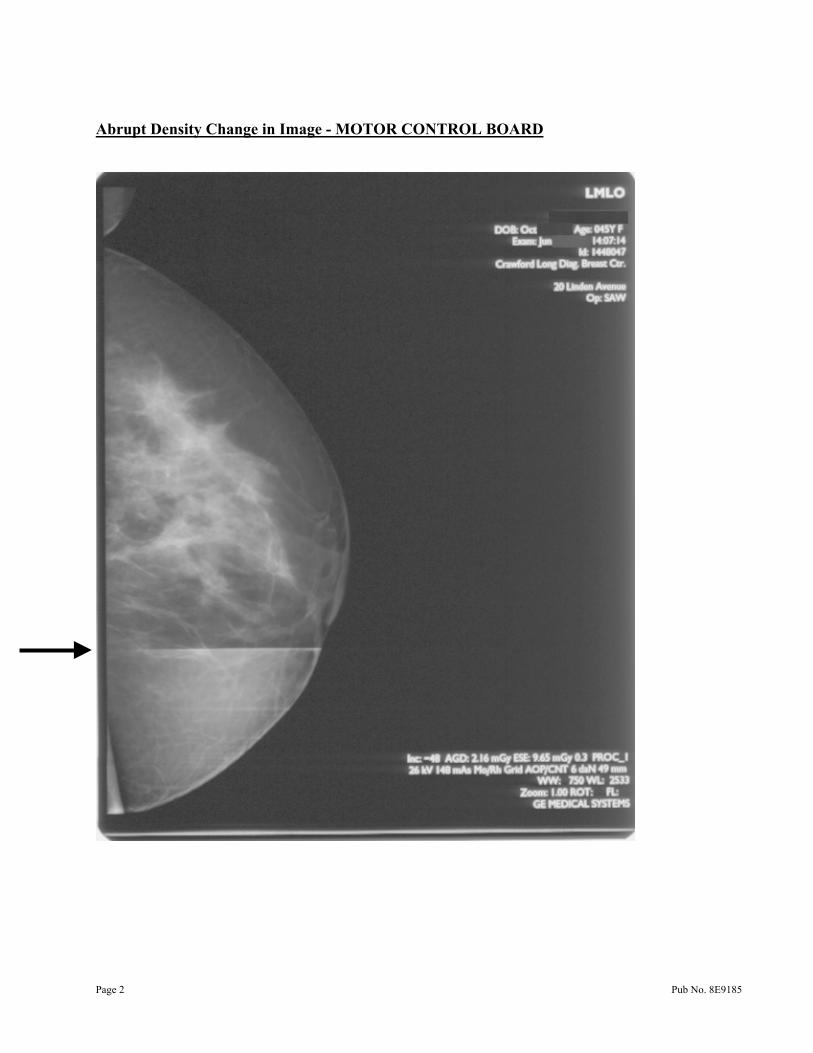
Abrupt Density Change in Image - MOTOR CONTROL BOARD
Page 2 Pub No. 8E9185
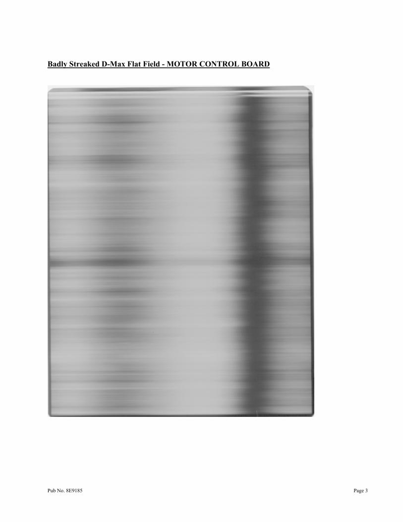
Badly Streaked D-Max Flat Field - MOTOR CONTROL BOARD
Pub No. 8E9185 Page 3
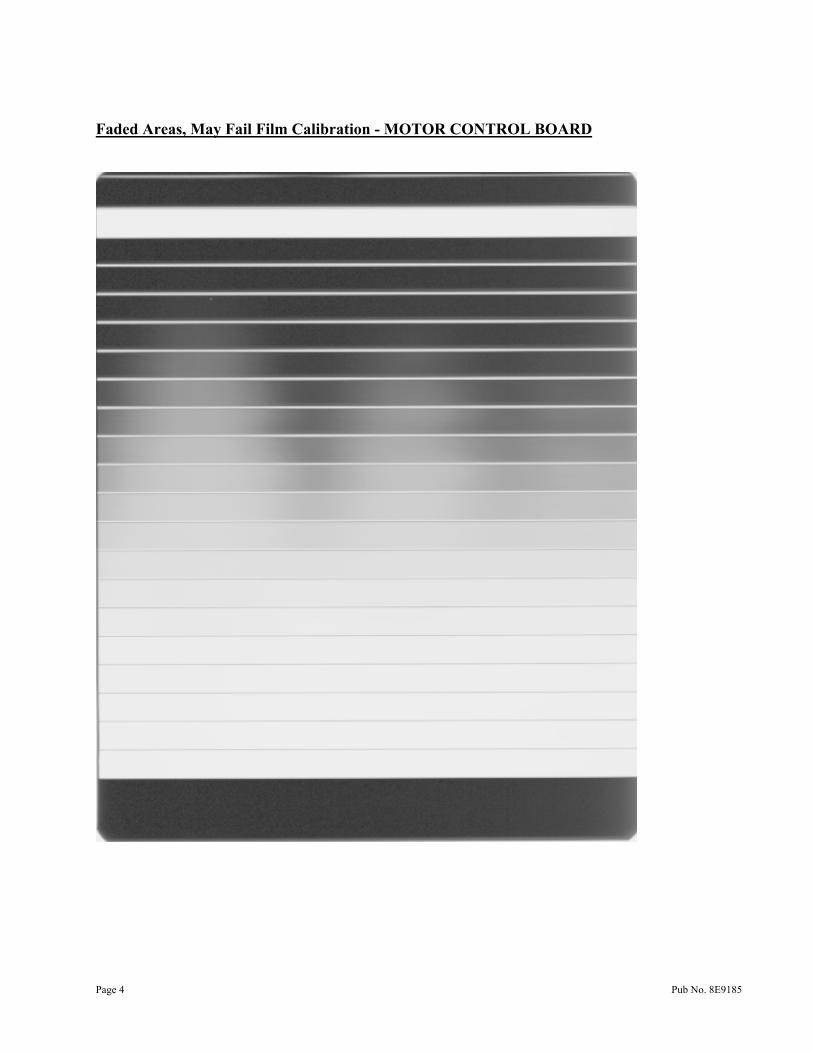
Faded Areas, May Fail Film Calibration - MOTOR CONTROL BOARD
Page 4 Pub No. 8E9185
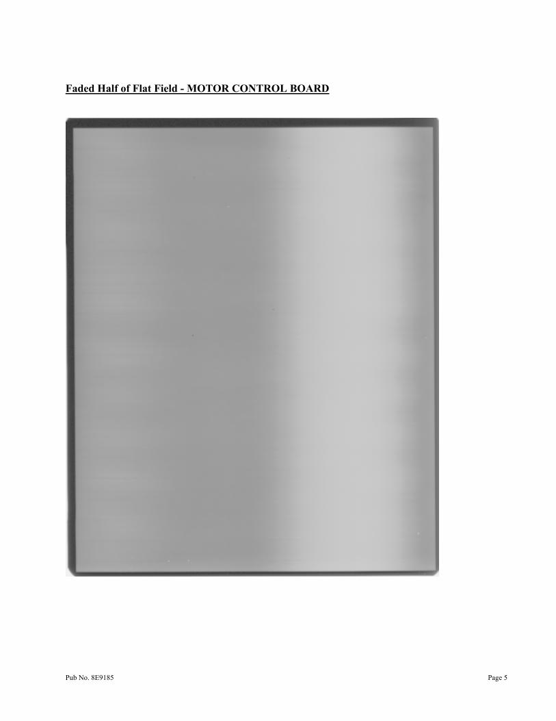
Faded Half of Flat Field - MOTOR CONTROL BOARD
Pub No. 8E9185 Page 5
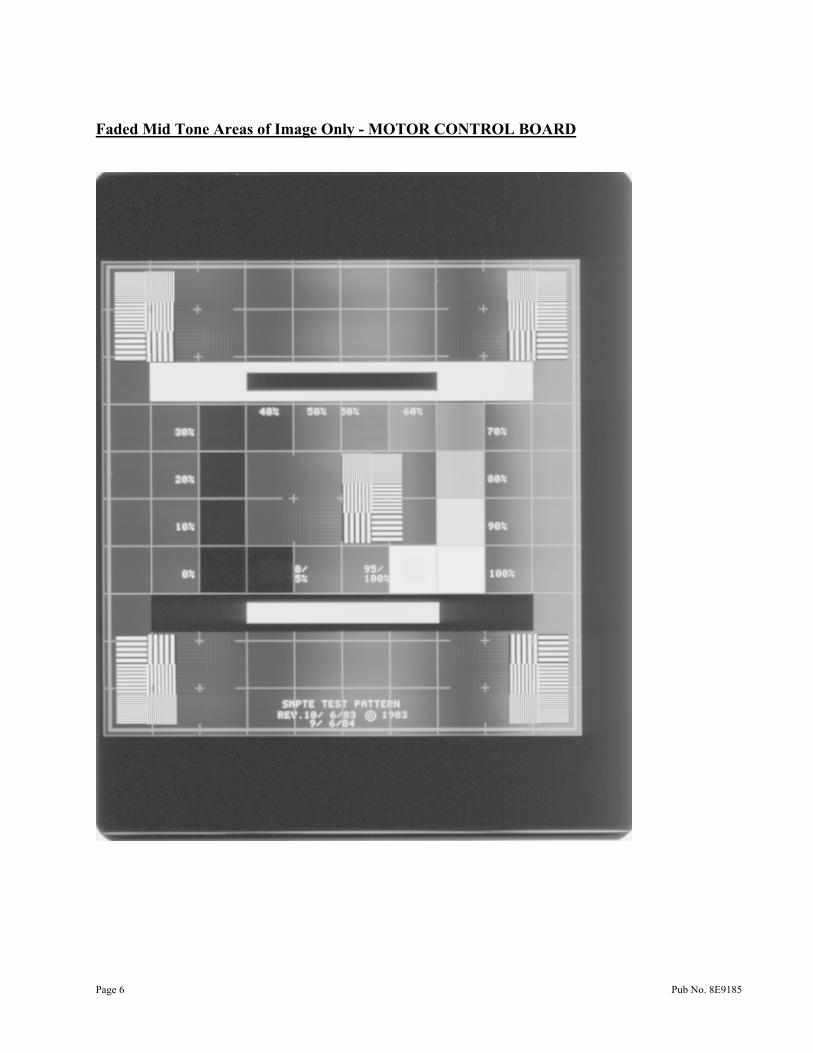
Faded Mid Tone Areas of Image Only - MOTOR CONTROL BOARD
Page 6 Pub No. 8E9185
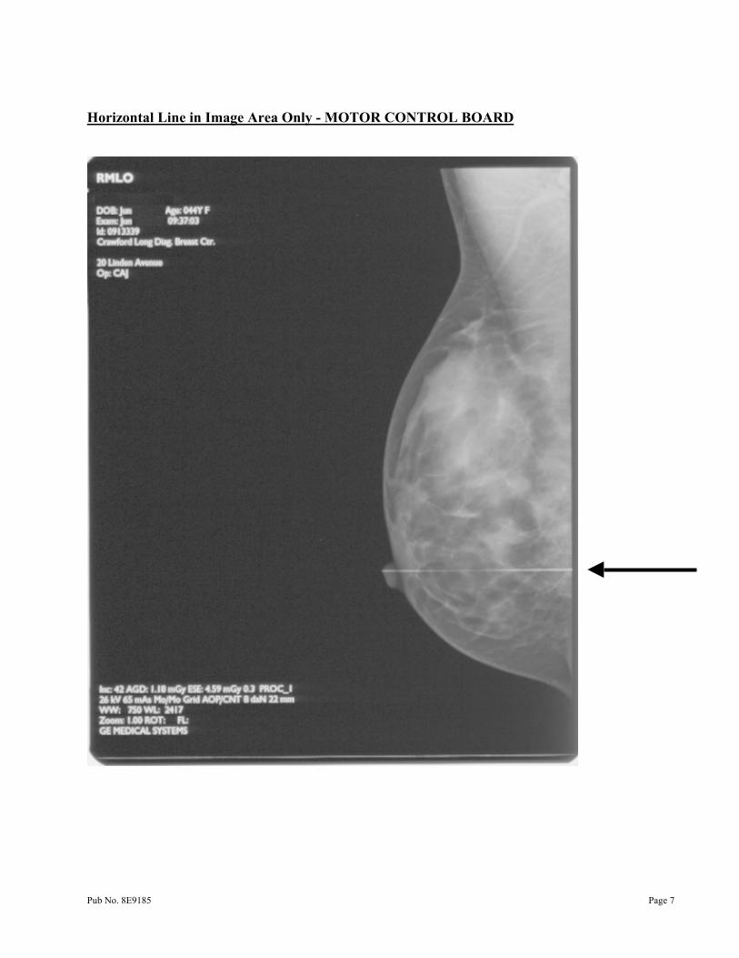
Horizontal Line in Image Area Only - MOTOR CONTROL BOARD
Pub No. 8E9185 Page 7
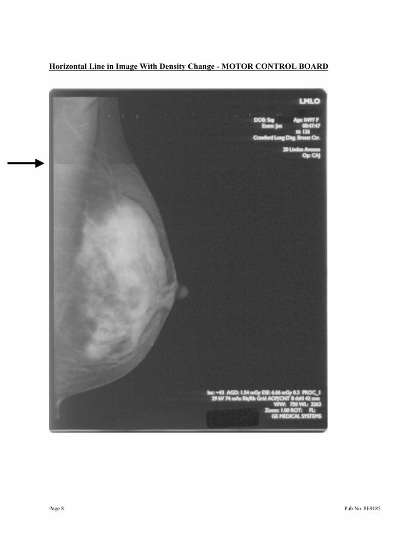
Horizontal Line in Image With Density Change - MOTOR CONTROL BOARD
Page 8 Pub No. 8E9185
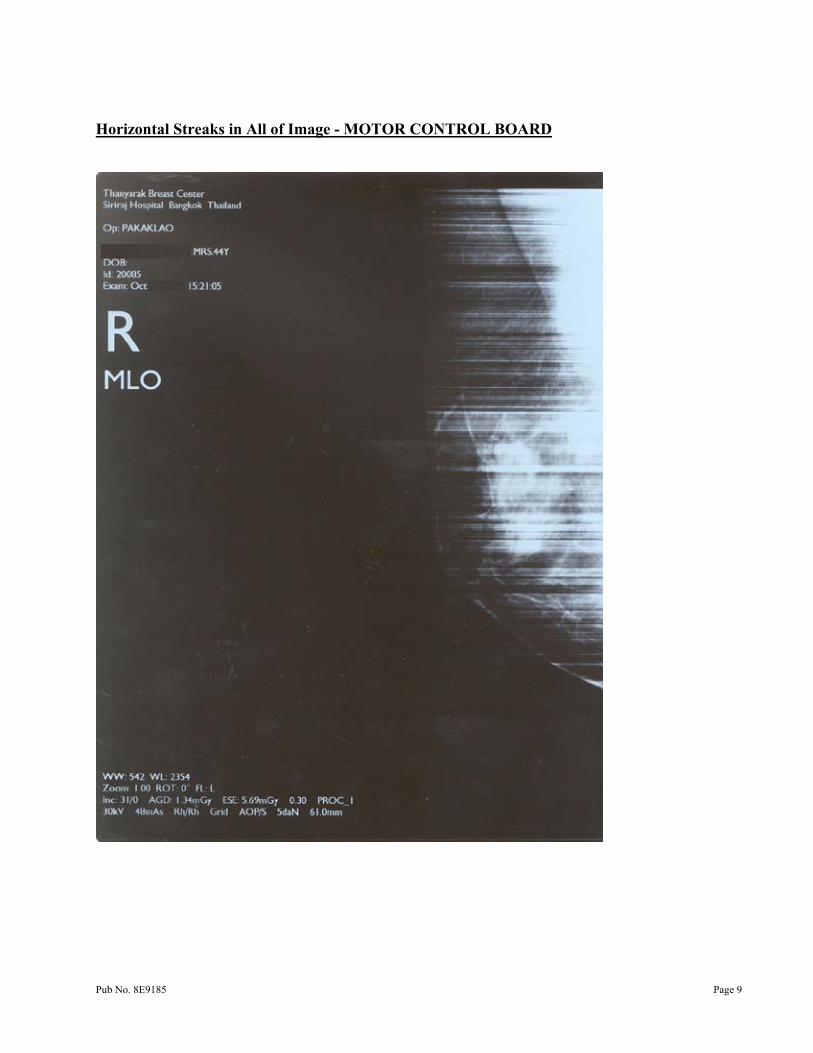
Horizontal Streaks in All of Image - MOTOR CONTROL BOARD
Pub No. 8E9185 Page 9
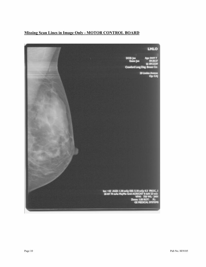
Missing Scan Lines in Image Only - MOTOR CONTROL BOARD
Page 10 Pub No. 8E9185
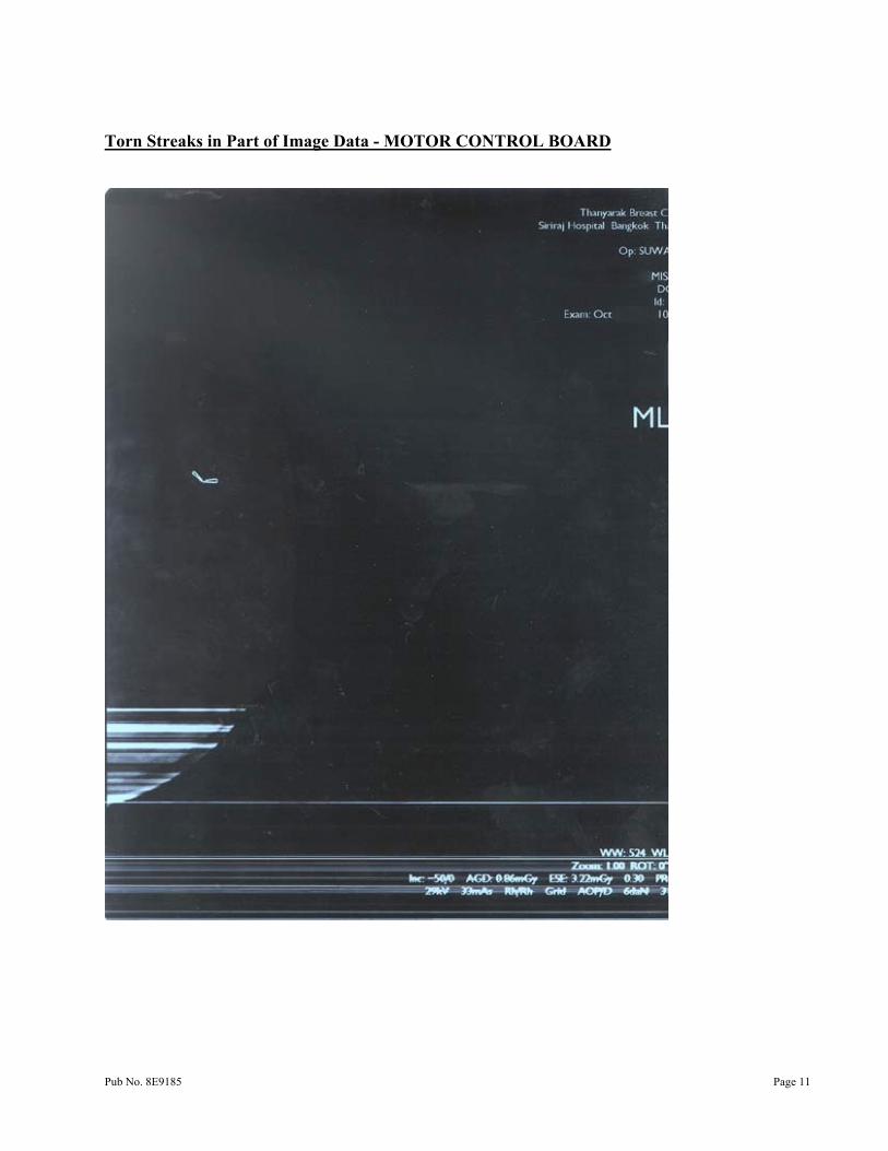
Torn Streaks in Part of Image Data - MOTOR CONTROL BOARD
Pub No. 8E9185 Page 11

Gary Ketch, Service Engineer-Oakdale
For more information please contact:
Eastman Kodak Company Health Imaging 1 Imation Way Discovery Building 3B-62 Oakdale, MN 55128-3414, USA 1-800-328-2910
Kodak and DryView are trademarks.
Printed in the USA. Pub No. 8E9185 ©Eastman Kodak Company Rochester, NY 14650 HEALTH IMAGING

Printed in the USA. Pub No. 8E6812 ©Eastman Kodak Company Rochester, NY 14650 HEALTH IMAGING
Gary Ketch, Service Engineer-Oakdale For more information please contact:
Eastman Kodak Company Health Imaging 1 Imation Way Discovery Building 3B-62 Oakdale, MN 55128-3414, USA 1-800-328-2910
Kodak and DryView are trademarks.
SERVICE BULLETIN
Health Imaging Products
Eastman Kodak Company, Health Imaging, Rochester, NY 14650
SERVICE BULLETIN NO. 01 APRIL 2003
1425, 1426, and 1427 Kodak DryView 8300 LASER IMAGING SYSTEMS
1437, 1438, and 1439 Kodak DryView 8600/8610 LASER IMAGING SYSTEMS
New DRUM Available Purpose The purpose of this service bulletin is to communicate the availability of the new “pink” DRUM that is being shipped in all 8300 LASER IMAGING SYSTEMS starting with serial number 83CL3084 and in all 8600/8610 LASER IMAGING SYSTEMS starting with serial number 86EC1421.
Implementation The DRUMS and PROCESSOR ASSEMBLIES containing these DRUMS will be phased into Service Parts inventory as the older red (8300) and gray (8600/8610) DRUM stocks are depleted.
This new “pink” DRUM has been previously referred to as the “red” DRUM in the 8100/8200 and 8500/8700 programs. However, it is the same material and the other programs will soon be referring to their “red” DRUMS as “pink” DRUMS.
Unlike the 8100/8200 and 8500/8700 programs, the “pink” DRUMS are not intended to extend the PM cycle. Until a more specific cleaning procedure is defined in the service manuals, the current 8300, 8600 and 8610 DRUM cleaning procedure can continue to be followed.
Eastman Kodak Company, 2003 Pub No. 8E9123

Gary Ketch, Service Engineer-Oakdale
For more information please contact:
Eastman Kodak Company Health Imaging 1 Imation Way Discovery Building 3B-62 Oakdale, MN 55128-3414, USA 1-800-328-2910
Kodak and DryView are trademarks.
Printed in the USA. Pub No. 8E9123 ©Eastman Kodak Company Rochester, NY 14650
HEALTH IMAGING
Deleted Technical Bulletins • Aspect Ratio (see Section 2 of Service Manual) • ATL Demo Van User ID Numbers (see Section 5 of Service Manual) • ATL HDI 3000 Video Calibration Test Patterns (see Section 5 of Service Manual) • ATL HDI MO Print Setup (see Section 5 of Service Manual) • ATL Purchase Agreement (Deleted) • Clicking Sound from Left Side of Imager (see Section 7 of Service Manual) • Compound Pully at SPC (see Section 8 of Service Manual) • Default Router Address (see Section 2 of Service Manual) • DICOM Troubleshooting with Ethernet (ControlE) Debug Menu (see Section 7 of
Service Manual) • Drum Temperature Errors (see Section 7 of Service Manual) • EC27 or EC28 – Film Stopping in Processor (see Section 7 of Service Manual) • Error Code 20 Repeats (see Section 7 of Service Manual) • Exchange Program for Repairable Items (Deleted) • Film Stops in the Processor Assembly (see Section 7 of Service Manual) • Film Tray Unlocking (see Section 7 of Service Manual) • “ Film Tray Won’t Unlock” Error Message (see Section 7 of Service Manual) • Flash EPROM Failure Recovery Procedure (see Section 7 of Service Manual) • Intermittent A to D Converter Errors (see Section 7 of Service Manual) • Introducing the DryView 8600 Laser Imager (Deleted) • Lamp Fails to Reach Temperature (see Section 7 of Service Manual) • Light Density at the Top of Film (see Section 7 of Service Manual) • Load New System Software When Replacing the CPU Board (see Section 4 of
Service Manual) • Local Panel Blank at Power-Up (see Section 7 of Service Manual) • Lot Numbers for DryView DVB (Blue) Film (Deleted) • Lower Felt Stripper Pad, New (see Section 7 of Service Manual) • Memory SIMM Needs to be in Lower Slot (see Section 4 of Service Manual) • Mini-Hub Required When Connecting 8300 to 10 Base 2 Network (see Section 2 of
Service Manual) • Missing “ Configure Client Defaults” Menu Item (see Section 7 of Service Manual) • Network Parameter Changes (see Section 2 of Service Manual) • Network Software in New 8300s May Not be the Latest (see Section 4 of Service
Manual) • Outdated Version 2.1 Network Firmware (Deleted) • POEIB No Longer Available (Deleted) • Possible Video Problem (see Section 7 of Service Manual) • Power Distribution Error and/or Laser Board Failure with 9410 Connected (see
Section 7 of Service Manual) • “ Processing Failure” DICOM Error Message at the Modality (see Section 7 of
Service Manual) • Processor Drum Related Error Codes (see Section 7 of Service Manual) • Scratching (see Section 7 of Service Manual) • Service Manual, DryView Laser Imager (Deleted) • Service Manual Update (Deleted) • Service Manual Update (Deleted)

• Software Correction for Pixely Images (Deleted) • Software Version 4.2 Highlights (Deleted) • Sony. Color Printer Option Availability (Deleted) • Thermal Fuse Upgrade/Replacement Overview (see Section 4 of Service Manual) • Thin Horizontal Line Across Width of Film (see Section 7 of Service Manual) • Thumping Sound from Left Side of Imager (see Section 7 of Service Manual) • ULUT, Options, New (see Section 2 of Service Manual) • Unable to Feed Film – Error Code 31 (see Section 7 of Service Manual) • Versions 4.2 and 4.4 Status and Error Messages (see Section 7 of Service Manual) • Video Connections in OEM Demo Vans (see Section 2 of Service Manual)
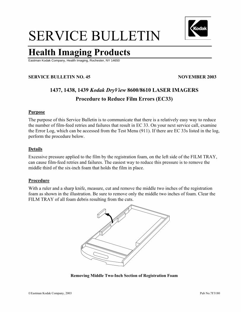
SERVICE BULLETIN Health Imaging Products
Eastman Kodak Company, Health Imaging, Rochester, NY 14650
SERVICE BULLETIN NO. 45 NOVEMBER 2003
1437, 1438, 1439 Kodak DryView 8600/8610 LASER IMAGERS Procedure to Reduce Film Errors (EC33)
Purpose
The purpose of this Service Bulletin is to communicate that there is a relatively easy way to reduce the number of film-feed retries and failures that result in EC 33. On your next service call, examine the Error Log, which can be accessed from the Test Menu (911). If there are EC 33s listed in the log, perform the procedure below.
Details
Excessive pressure applied to the film by the registration foam, on the left side of the FILM TRAY, can cause film-feed retries and failures. The easiest way to reduce this pressure is to remove the middle third of the six-inch foam that holds the film in place.
Procedure
With a ruler and a sharp knife, measure, cut and remove the middle two inches of the registration foam as shown in the illustration. Be sure to remove only the middle two inches of foam. Clear the FILM TRAY of all foam debris resulting from the cuts.
Removing Middle Two-Inch Section of Registration Foam
Eastman Kodak Company, 2003 Pub No.7F3180
Gary J. Ketch, Service Engineer-Oakdale
For more information please contact:
Eastman Kodak Company Health Imaging 1 Imation Way Discovery Building 3B-62 Oakdale, MN 55128-3414, USA 1-800-328-2910
Kodak and DryView are trademarks.
Printed in the USA. Pub No. 7F3180 ©Eastman Kodak Company, 2003 Rochester, NY 14650
HEALTH IMAGING
SERVICE BULLETIN Health Imaging Products
Eastman Kodak Company, Health Imaging, Rochester, NY 14650
Eastman Kodak Company, 2004 Eastman Kodak Company Restricted Pub No. 7F6200
SERVICE BULLETIN NO. 861 APRIL 2004
Kodak DryView 8600/8610 LASER IMAGERS
Service Codes: 1437, 1438, 1439
ProComm Plus COMMUNICATIONS PROGRAM To Be Used When Uploading System Software
Purpose
The purpose of this Service Bulletin is to communicate that the Hyperterminal COMMUNICATIONS PROGRAM does not function adequately when used with the newest models of LAPTOP COMPUTERS.
Description
The inefficiency of the Hyperterminal COMMUNICATIONS PROGRAM, when used with the new higher-speed LAPTOP COMPUTERS, can cause it to take up to four hours to upload new system software into the Kodak DryView 8600/8610 LASER IMAGERS. The Pro Comm Plus COMMUNICATIONS PROGRAM is a more sophisticated program that will allow software uploads to take no longer than 10-12 minutes. In addition, the ProComm Plus COMMUNICATIONS PROGRAM will provide an estimate of the total time required for a software upload as well as a progress gauge.
Procedure
The next time you install a software upgrade in a Kodak DryView 8600/8610 LASER IMAGER, follow the procedure in paragraph 2-17-2 in the SERVICE MANUAL for the Kodak DryView 8600/8610 LASER IMAGERS.

Printed in the USA. Pub No. 7F6200 ©Eastman Kodak Company, 2004 Rochester, NY 14650
HEALTH IMAGING
Gary Ketch, Service Engineer-Oakdale
For more information please contact:
Eastman Kodak Company Health Imaging 1 Imation Way Discovery Building 3B-62 Oakdale, MN 55128-3414, USA 1-800-328-2910
Kodak and DryView are trademarks of Eastman Kodak Company.
SERVICE BULLETIN Health Imaging Products
Eastman Kodak Company, Health Imaging, Rochester, NY 14650
Eastman Kodak Company, 2004 Pub No. 8F0642
SERVICE BULLETIN NO. 942 November 2004
Kodak DryView 8600/8610 LASER IMAGERS
Service Codes: 1437, 1438, 1439
Re-Issue: New System Software to Accommodate Film Offerings
Purpose The purpose of this Service Bulletin is to communicate that new system software being released to the field that will allow both imagers to print images on new, faster film.
Originally, the software was developed for future film offerings, but we have since found that it is often needed to allow DVM Version 3.0, Catalog Number 864-0823, film to function properly in some imagers.
The plan now is to update all imagers in the field with a required modification to permit the introduction of new faster film such as DVM Version 3.0.
Details The system software to accomplish this is Version 2.5 for the Kodak DryView 8600 LASER IMAGER and Version 2.4 for the Kodak DryView 8610 LASER IMAGER. The system software is different for each model of imager and is not interchangeable. This software includes the most recent contrast tables and correction of some minor bugs. Additionally, in the case of the Kodak DryView 8610 LASER IMAGER, this software simplifies the adjustment of the processor temperature by eliminating the need for end zone adjustment. The software for both imagers is downloaded from the “86upgrade” folder on the Service Collection CD, using the procedure in the Service Manual for the Kodak DryView 8600/8610 LASER IMAGERS and by following the instructions in Modification Number 1.
Page 2 Pub No. 8F0642
Kodak DryView 8600 LASER IMAGER, Version 2.5 Changes In addition to allowing faster film to be used in the imager and correcting some minor internal bugs, Version. 2.5 will also provide the following features:
The film calibration will have 23 bands instead of 20. Contrast tables will be updated to 6.G.7. Host control (831, 952) commands can now be monitored at the serial service port with
a service computer by pressing [CTRL] A, after Debug is enabled (CTRL D). Each incoming command will be represented by A<, and A> will represent each response. Retransmitted imager responses to the host will be indicated with A+>.
Fewer progress dots will be sent back to the service computer, which should allow future system software to be downloaded faster.
When a film calibration fails on the last sheet of film, calibration will resume when new film is loaded.
Kodak DryView 8610 LASER IMAGER, Version 2.4 Changes In addition to allowing faster film to be used in the imager and correcting some minor internal bugs, Version. 2.4 will provide the following features:
The film calibration sheet will have 23 bands instead of 20. Contrast tables will be updated to 6.P.2. Calibration with a temperature meter of the end zone of the drum is no longer required.
The end zone is now calculated as a percentage of the center zone. After downloading the system software, and then accessing the End Zone installation menu, the end zone should be manually set to 100 percent.
To aid in troubleshooting the premature ejection of a full or partially full film tray, “FILM TRAY EMPTY – INSERT FILM (29)” error message is logged in the error log when all of the following conditions are met:
o Film tray is ejected o Out of film switch is activated o Film counting is enabled o Film count (number of sheets fed) is not 100.
Page 3 Pub No. 8F0642
Procedure
The procedure in the Service Manual for the Kodak DryView 8600/8610 LASER IMAGERS and the Mod 1 instructions refer to installing software upgrades using the HyperTerminal program that is resident in the Windows OPERATING SYSTEMS (OS). However, while the HyperTerminal program was adequate for older service computers using the Windows 95 OS, the download process is too slow when using the program with the newer service computers. Users of newer service computers must use a more sophisticated program such as ProComm Plus to be able to download the imager system software in less than one half hour. Follow the setup instructions for ProComm Plus in Section 2-17-2 in the Service Manual for the Kodak DryView 8600/8610 LASER IMAGERS.
Printed in the USA. Pub No. 8F0642 ©Eastman Kodak Company Rochester, NY 14650
HEALTH IMAGING
For more information please contact:
Glen Moede / Gary Ketch, Service Engineer-Oakdale Eastman Kodak Company Health Imaging 1 Imation Way Discovery Building 3B-62 Oakdale, MN 55128-3414, USA 1-800-328-2910
Kodak and DryView are trademarks of Eastman Kodak Company.
SERVICE BULLETIN Health Imaging Products
Eastman Kodak Company, Health Imaging, Rochester, NY 14650
©Eastman Kodak Company, 2004 Eastman Kodak Company Restricted Pub No.7F6993
SERVICE BULLETIN NO. 903 AUGUST 2004
Kodak DryView 8600 LASER IMAGER Service Codes: 1437, 1438
Kodak DryView 8610 LASER IMAGER Service Code: 1439
Procedure to Address FILM Calibration Failures that May Occur After Version 3.0 FILM is Loaded for the First Time
Purpose
The purpose of this service bulletin is to communicate the steps that should be taken to correct FILM calibration failures that may occur after a customer loads Kodak DVM (Ver 3.0) Catalog Ref # 864 0823 FILM into their Kodak DryView 8600/8610 LASER IMAGER for the first time.
Procedure
Follow this procedure if FILM calibration failures occur immediately after a customer switches from DVM (Ver 2.5) Catalog Ref # 839 5139 FILM to DVM (Ver 3.0) Catalog Ref # 864 0823 FILM.
1. Because each occurrence must be tracked, first call the TSC, Level 2 and report the situation. Provide the account name, the serial number of the IMAGER, and the lot number of the FILM. The TSC engineer will record the information and ask you to perform the steps following this one.
2. Check the temperature of the PROCESSOR DRUM with a TEMP METER known to be in good calibration.
3. If the temperature of the PROCESSOR DRUM is not within the 122.2 ± 1 degree C specification, follow the temperature calibration procedure in Section 3-1 of the SERVICE MANUAL for the Kodak DryView 8600/8610 LASER IMAGING SYSTEM/for Mammography 74-0401-8699-6.
4. Have the IMAGER perform a FILM calibration.
a. If the FILM calibration passes, notify the TSC engineer and complete the service call.
b. If the FILM calibration fails again or if the temperature of the PROCESSOR DRUM is in specification, continue with Step 5.
Printed in the USA. Pub No. 7F6993 ©Eastman Kodak Company, 2004 Rochester, NY 14650 HEALTH IMAGING
5. Connect a Service Computer to the IMAGER, launch a terminal program, and capture the debug log (Ctrl+D) while the FILM calibration is being performed.
6. Analyze the log using the guidelines in Section 7-1-2-2 in the SERVICE MANUAL for the 8600/8610 LASER IMAGING SYSTEM/for Mammography 74-0401-8699-6.
7. If the cause of the FILM calibration failure is not apparent after analyzing the log, e-mail the log to the TSC engineer with whom you are working.
Note: The TSC engineer might engage a Service Engineer if necessary. Service Engineering may then suggest uploading one of the following System Software versions:
! Version 2.5 for an 8600 LASER IMAGER
! Version 2.4 for an 8610 LASER IMAGER
8. If none of the suggestions results in a successful FILM calibration, escalate the account.
Note: TSC engineer will make arrangements to have a case of DVM (Ver 2.5) Catalog Ref # 839 5139 FILM shipped to the account so that the customer can continue imaging while Service Engineering assists in obtaining a solution for the escalation.
Gary Ketch, Glenn Moede, Service Engineers – Oakdale, MN
For more information please contact:
Eastman Kodak Company Health Imaging – TSC 6200 Tennyson Parkway Plano, TX 75024, USA (800) 544-7009
Kodak and DryView are trademarks.
SERVICE BULLETIN
Health Imaging Products
Eastman Kodak Company, Health Imaging, Rochester, NY 14650
©Eastman Kodak Company, 2004 Eastman Kodak Company Restricted Pub No. 7F6651
SERVICE BULLETIN NO. 885 June 2004
Kodak DryView 8600 LASER IMAGER
Kodak DryView 8610 LASER IMAGER
Service Codes: 1437, 1438, 1439
New Solution for EC 27 or EC 28 Caused by FILM Stalling in the PROCESSOR
Purpose
The purpose of this Service Bulletin is to communicate that the cause of, and solution for, FILM stalling in the PROCESSOR has been determined.
Description
The main cause of FILM stalling in the PROCESSOR is the inability of the RUBBER IDLER ROLLER at the entrance to the PROCESSOR to turn freely as FILM enters the PROCESSOR. This condition causes the FILM to slip and after some time, the software times out and displays EC 27 or EC 28.
Note: EC 28 is usually caused by FILM slipping at the entrance to the PROCESSOR. However, the EC is displayed when the FILM does not exit in the time expected by the software. This is because if the FILM gets a slow start into the PROCESSOR, the FILM may eventually pass through the PROCESSOR, but the FILM still does not exit in the time expected by the software.
Solution
If an IMAGER experiences repetitive EC 27 or EC 28 errors, replace the gray plastic BUSHINGS that hold the RUBBER IDLER ROLLER in place with a pair of METAL BALL BEARING BUSHINGS (7E9722). Replace the gray plastic BUSHINGS only at the PROCESSOR entrance.
Printed in the USA. Pub No. 7F6651 ©Eastman Kodak Company, 2004 Rochester, NY 14650
HEALTH IMAGING
Service Information
Gary Ketch, Service Engineer-Oakdale
For more information please contact:
Eastman Kodak Company Health Imaging 1 Imation Way Discovery Building 3B-62 Oakdale, MN 55128-3414, USA 1-800-328-2910
Kodak and DryView are trademarks of Eastman Kodak Company.
SERVICE BULLETIN Health Imaging Products
Eastman Kodak Company, Health Imaging, Rochester, NY 14650
©Eastman Kodak Company, 2004 Eastman Kodak Company Restricted Pub No. 7F6592
SERVICE BULLETIN NO. 882 June 2004
Kodak DryView 8600 LASER IMAGING SYSTEM
Kodak DryView 8610 LASER IMAGING SYSTEM
Service Codes: 1437, 1438, 1439
Customer QC Control Charts Going Out of Control with Version 3.0 DVM FILM
Purpose
The purpose of this service bulletin is to communicate how to respond when customers place service calls because their QC charts are suddenly out of control after they begin using Version 3.0 DVM FILM (Catalog Reference Number 864-0823).
Description
Since Version 3.0 is currently being rolled out to our customers worldwide, they may start to experience their daily QC Control Charts suddenly going out of control. If customers indicate that when they started using a new shipment of FILM, their daily QC suddenly was out of control, ask customers if they have created a new baseline for the new FILM. Many customers have gotten comfortable over time with the stability of the AIQC system and have become lax in performing this procedure. Also, customers may think that creating a new baseline is the same as doing a five-day average like wet processor systems and they feel that creating a new baseline is too time-consuming.
Procedure
Direct customers to Section 4 of the following manuals:
! User Guide for the Kodak DryView 8600 LASER IMAGING SYSTEM / for Mammography
! User Guide for the Kodak DryView 8610 LASER IMAGING SYSTEM / for Mammography
Remind customers that Kodak recommends that they create a new baseline every time they insert FILM with a new emulsion number into their IMAGER. This is especially important for customers when they convert to Version 3.0 FILM because it is a very different emulsion than the one they were using previously. Once customers establish a new baseline, their system should then remain in control.
Printed in the USA. Pub No. 7F6592 ©Eastman Kodak Company, 2004 Rochester, NY 14650
HEALTH IMAGING
Customers may prefer not to print five QC STEP WEDGE FILMS in a row to establish a new baseline as recommended in Section 4. Advise customers that because the stability of the LASER IMAGERS has been established over time, they can still establish an effective new baseline by printing only two FILMS in a row and then averaging the density values.
Gary Ketch, Service Engineer-Oakdale
For more information please contact:
Eastman Kodak Company Health Imaging 1 Imation Way Discovery Building 3B-62 Oakdale, MN 55128-3414, USA 1-800-328-2910
Kodak and DryView are trademarks of Eastman Kodak Company.