Embed Size (px)
Citation preview

POMORSTVO • Scientific Journal of Maritime Research • 26/2(2012) • str./pp. 289-306 289
Aleksandar Cuculić, mag. ing.Dr. sc. Dubravko Vučetić / Ph. D. Sveučilište u Rijeci / University of RijekaPomorski fakultet u Rijeci / Faculty of Maritime Studies RijekaStudentska 2, 51000 Rijeka
Dr. sc. Danko Kezić / Ph. D.Sveučilište u Splitu / University of SplitPomorski fakultet / Faculty of Maritime StudiesZrinsko-frankopanska 38, 21000 Split
Hrvatska / Croatia
Izvorni znanstveni rad Original Scientific Paper
UDK / UDC: 621.314.26
629.5.03
Primljeno / Received: 23. rujna 2012. / 23rd September 2012
Odobreno / Accepted: 29. listopada 2012. / 29th October 2012
KOMPARATIVNA ANALIZA METODA ŠIRINSKO-IMPULSNE MODULACIJE PROPULZIJSKOG PRETVARAČA FREKVENCIJE
COMPARATIVE ANALYSIS OF THE PULSE WIDTH MODULATION
METHODS FOR THE PROPULSION FREQUENCY CONVERTER
SAŽETAK
U radu su pomoću simulacijskog modela razvijenog u programskom alatu Simulink analizirane tri najčešće korištene metode širinsko-impulsne modulacije: metoda histereze, sinusno-trokutna metoda i metoda modulacije prostornog vektora. Simulacija je izvršena u vremenskoj domeni, a za analizu rezultata je primijenjen kvazistacionarni pristup. Usporedno su analizirani valni oblici i harmonička izobličenja statorskih napona i struja propulzijskog elektromotora pri različitim brzinama vrtnje i odgovarajućim opterećenjima za sve tri metode modulacije. Dobiveni rezultati pokazuju da su pri približno istim frekven-cijama prekapčanja ukupna harmonička izobličenja napona i struje propulzijskog elektromotora uvjerljivo najmanja kod metode modulacije prostornog vektora, a najveća kod metode histereze. Indeks frekventne modulacije ima relativno mali utjecaj na THDu, ali vrlo velik utjecaj na THDi.
Ključne riječi: širinsko-impulsna modulacija, električna propulzija, brod, pretvarač frekvencije, modulacijske tehnike
SUMMARY
In this paper, using a simulation model developed in Simulink, the three most common Pulse Width Modulation techniques are analyzed: hysteresis current control method, sine-triangle method, and space vector modulation method. Simulation is performed in the time domain and a quasi-stationary approach is applied for the simulation results analysis. Waveforms and harmonic distortion of propulsion motor’s stator voltage and current are analyzed at different speeds and appropriate loads for all three modulation methods. The obtained results indicate that, at approximately equal switching frequencies, the total harmonic distortions of propulsion motor voltage and current are arguably lowest when the space vector modulation method is used and are highest with the hysteresis current control method. Frequency modulation index has a relative small impact on THDu and a very large impact on THDi.
Key words: Pulse Width Modulation, electric propulsion, ship, frequency converter, modulation techniques

A. Cuculić, D. Vučetić, D. Kezić: KOMPARATIVNA ANALIZA METODA ŠIRINSKO-IMPULSNE...
290 POMORSTVO • Scientific Journal of Maritime Research • 26/2(2012) • str./pp. 289-306
1. UVOD
Na plovilima s električnom propulzijom da-nas prevladava koncept kod kojeg je sustav električne propulzije potpuno integriran unutar elektroenergetskog sustava plovila (IEP–Inte-grated electrical propulsion). Brzina vrtnje pro-pulzijskih elektromotora regulira se pomoću statičkih pretvarača frekvencije napajanih iz brodske mreže konstantnog napona i frekvenci-je. Pretvarač frekvencije ključna je komponenta takvog sustava, o kojoj u velikoj mjeri ovise nje-gova efikasnost i dinamički odziv.
U počecima primjene, jedino su mrežno ko-mutirani tiristorski pretvarači mogli dati dovoljno veliku snagu za pogon propulzijskih ele ktromotora. Tu se prvenstveno misli na ciklo koverter i sinkrokonverter kao tipične predstavnike ovoga tipa pretvarača [1].
Pretvarači koji koriste poluvodičke ventile s mogućnošću prisilne, odnosno programirane komutacije imaju bolje karakteristike i manja harmoničkaizobličenja, ali je njihova upotreba za velike snage bila sve donedavno ili preskupa, ili vrlo teško izvediva. Tek je razvoj na polju energetske elektronike tijekom proteklog de-setljeća omogućio njihovu primjenu i kod elek-tromotornih pogona velikih snaga.
Tome je svakako išao u prilog i stalan pad ci-jena poluvodičkih komponenata. Širinsko-im-pulsno modulirani (ŠIM) pretvarači s utisnutim naponom su danas daleko najrasprostranjeniji tip ovakvih pretvarača frekvencije, uglavnom zahvaljujući njihovoj širokoj primjeni kod indu-strijskih elektromotornih pogona malih i sred-njih snaga. Zbog svoje kompatibilnosti sa svim vrstama izmjeničnih elektromotora i odličnih dinamičkih karakteristika nameću se kao opti-malan izbor u većini primjena, pa tako i kod brodske električne propulzije.
Smisao ovoga rada je komparativna analiza triju najčešćekorištenih metoda širinsko- im-pulsne modulacije (metode histereze, sinusno-trokutne metode (STM) i metode modulacije prostornog vektora (SVM)), s obzirom na kva-litetu napona i struje propulzijskog elektromo-tora napajanog pomoću pretvarača frekvencije s utisnutim naponom. Izvršena analiza temelje-na je na simulacijskom modelu.
1 INTRODUCTION
The Integrated Electric Propulsion (IEP), where the propulsion system is fully integrated into the ship’s power network, is the prevailing concept on board modern electrically propelled vessels. The speed of the propulsion motor is controlled by the static frequency converter supplied from the electrical network of con-stant voltage and frequency; therefore, it has a major influence on the efficiency and dynamic response of the IEP system.
In the beginning of the frequency converters application on board ships, only the naturally commutated thyristor converters (cycloconvert-er and synchroconverter) were able to provide sufficient power for propulsion motors [1].
Converters with force commutated switching devices have better properties and a lower har-monic distortion, but until recently, their appli-cation was limited to low and medium power ranges. However, the development of power electronics and a constant decline of semicon-ductor prices over the past decade enabled their use in high power electrical propulsion drives.
The Pulse Width Modulated (PWM) voltage source frequency converters are nowadays the most common type of electric motor drives, thanks to their wide application in industry, compatibility with all types of AC motors and excellent dynamic characteristics. They present an optimal choice for most of the applications, including the ship’s electrical propulsion.
The purpose of this paper is a comparative analysis of the three most common PWM meth-ods (hysteresis current control method, sine-triangle method (STM) and space vector mod-ulation method (SVM)), considering the quality of the propulsion electric motor voltage and current when fed by a voltage source PWM frequency converter.
2 SIMULATION MODEL OF THE PROPULSION PWM VOLTAGE
SOURCE FREQUENCY CONVERTER
The model of a propulsion motor fed by the PWM frequency converter is shown in Figure 1.
A six-pulse two level PWM inverter is real-ized with six IGBTs and connected to the ship’s

A. Cuculić, D. Vučetić, D. Kezić: COMPARATIVE ANALYSIS OF THE PULSE WIDTH MODULATION METHODS...
POMORSTVO • Scientific Journal of Maritime Research • 26/2(2012) • str./pp. 289-306 291
2. SIMULACIJSKI MODEL PROPULZIJSKOG ŠIM
PRETVARAČA S UTISNUTIM NAPONOM
Model brodskog propulzijskog elektromoto-ra napajanog pomoću ŠIM pretvarača s utisnu-tim naponomprikazan je na slici 1.
Šesteropulsni ŠIM izmjenjivač s dvije napon-ske razine realiziran je pomoću šest IGBT-a i spojen na brodsku mrežu preko dvanaesteropul-snog ispravljačkog sklopa, koji se sastoji od tro-namotnog trofaznog transformatora u spoju Y/y/d i dva serijski spojena šesteropulsna diodna ispravljača. Dvanaesteropulsna konfiguracija ispravljačkog sklopa odabrana je iz razloga što se ona najčešće koristi kod brodske električne pro-pulzije, a ujedno daje dovoljno kvalitetan napon istosmjernog međukruga. Kako se u ovome radu primarno analiziraju naponi i struje propulzij-skog elektromotora, a ne i utjecaj na brodski elektroenergetski sustav, neupravljivi diodni mo-stovi u potpunosti zadovoljavaju postavljene uvjete i istovremeno omogućuju mnogo jedno-stavniju realizaciju simulacijskog modela, nego u slučaju primjene aktivnih ispravljača.
U modelu je na izlaz ŠIM izmjenjivača spo-jen kavezni asinkroni elektromotor, simuliran u stacionarnom referentnom okviru kod kojega se sve električne varijable i parametri preslika-vaju na stator te je stoga izuzetno pogodan za analizu struja i napona kojim pretvarač fre-kvencije napaja elektromotor (Slika 2) [2] [3].
power system via a twelve-pulse rectifier con-sisting of three-phase, three windings trans-former in Y/y/d connection and two six-pulse diode rectifiers connected in series. The twelve-pulse rectifier circuit is chosen due to its com-mon use in marine electrical propulsion and low ripple output voltage. As this paper prima-rily analyzes the propulsion motor voltage and current, and not the frequency converter im-
30/pi
Current
Torque
A
B
C
a2b2c2a3b3c3
Three-PhaseTransformer
(Three Windings)
g CE
T6
g CE
T5
g CE
T4
g CE
T3
g CE
T2
g CE
T1
A
B
C
Ship's electrical networkA
B
C
+
-
A
B
C
+
-
mABC
Tm
Propulsion electric motor
PWM PULSES
PWM Generator
f(u)
Fcn
-Udc
+Udc
<Rotor speed (wm)>
<Electromagnetic torque Te (N*m)>
<Stator current is_a (A)>
0
Slika 1. Simulink model propulzijskog elektromotora napajanog pomoću ŠIM pretvarača s utisnutim naponomFigure 1 Simulink model of propulsion motor feed from PWM voltage source converter
Izvor/Source: autori/authors
pact on the ship’s electrical system, passive di-ode bridges fully meet the set requirements, si-multaneously providing a much simpler implementation of the simulation model than in the case of an active rectifier application.
The induction motor, simulated in a station-ary reference frame (Figure 2) is connected to the output of the PWM inverter. The stationary reference frame, where all electrical variables and parameters are mapped to the stator side, is particularly suitable for the parameter analy-sis of the electric motor fed by adjustable speed drive[2][3].
The electrical model is described with the following equations (1 – 9):
(1)
(2)
(3)
(4)

A. Cuculić, D. Vučetić, D. Kezić: KOMPARATIVNA ANALIZA METODA ŠIRINSKO-IMPULSNE...
292 POMORSTVO • Scientific Journal of Maritime Research • 26/2(2012) • str./pp. 289-306
Električni model opisan je jednadžbama (1 – 9):
(1)
(2)
(3)
(4)
(5)
(6)
(7)
(8)
(9)
gdje su Rs iL1s otpor i rasipni induktivitet statora,R’ri L’1r otpor i rasipni induktivitet rotora, Lm glavni induktivitet, Ls, L’r ukupni in-duktiviteti statora i rotora,Uqs, iqs napon i struja statora na q osi, U’qr, i’qr, napon i struja rotora na q osi,Uds, idsnapon i struja statora na d osi, U’dr, i’dr napon i struja rotora na d osi, fqs, fds ma-
dsi
sR lsLmL
'r qrω φ− 'dri
+
-
+
-
dsU 'drU'lrL 'rR
qsi
sR lsLmL
'r drω φ− 'qri
+
-
+
-
qsU 'qrU
q-axis
'lrL 'rR
d-axis
Slika 2. Nadomjesna shema kaveznog asinkronkronog motora u stacionarnom referentnom okviruFigure 2 Induction motor equivalent circuit in stationary reference frame
Izvor/Source: autori prema [2] i [3] / authors according to [2] and [3]
(5)
(6)
(7)
(8)
(9)
where Rs i L1s are stator resistance and leak-age inductance, R’r i L’1r rotor resistance and leakage inductance, Lm main inductance, Ls, L’r stator and rotor total inductances, Uqs, iqs stator voltage and current on q-axis, U’qr, i’qr, rotor voltage and current on q-axis, Uds, ids stator volt-age and current on d-axis, U’dr, i’dr rotor voltage and current on d-axis, fqs, fds stator magnetic fluxes on q-axis and d-axis, f’qr, f’dr rotor mag-netic fluxes on q-axis and d-axis and p is the number of pole pairs.
The mechanical system dynamic included in the induction motor model is described with the equation (10):
(10)
where ωr is an electric angular speed, Te an elec-tromagnetic torque, Tm a mechanical load torque, J a total rotor and load inertia coeffi-

A. Cuculić, D. Vučetić, D. Kezić: COMPARATIVE ANALYSIS OF THE PULSE WIDTH MODULATION METHODS...
POMORSTVO • Scientific Journal of Maritime Research • 26/2(2012) • str./pp. 289-306 293
gnetski tokovi statora na d i q osi, f’qr, f’dr ma-gnetski tokovi rotora na d i q osi i p− broj pari polova.
Dinamika mehaničkog sustava koji je uklju-čen u model asinkronog motora opisana je po-moću jednadžbe (10):
(10)
gdje su: električna kutna brzina, Te elektroma-gnetski moment, Tm moment tereta, J ukupni moment inercije rotora i tereta spojenog na osovinu motora i F ukupni koeficijent trenja ro-tora i tereta spojenog na osovinu motora [2] [3].
Moment tereta koji razvija brodski vijak Tm približno je proporcionalan kvadratu brzine:
(11)
gdje je K je konstanta određena nazivnim vri-jednostima momenta i brzine vrtnje motora, a ωm kutna brzina rotora.
Odabran je prikaz veličina u relativnim jedi-nicama, odnosno Per-Unit (p.u.) sustavu. To znači da je vrijednost pojedinih veličina (napon, struja, moment, ...) izražena kao omjer izmjere-ne i nominalne vrijednosti. Takav sustav je oda-bran zbog lakšeg i zornijeg prikaza međuodno-sa mjerenih veličina, ali i iz jednog čisto praktičnog razloga. Naime, p.u. sustav je vrlo pogodan za modeliranje elektromotora, zbog toga što se vrijednosti reaktancija izražene u re-lativnim jedinicama vrlo malo mijenjaju prili-kom promjene vrijednosti napona napajanja i snage elektromotora. Čest je slučaj da su po-znati osnovni parametri motora, ali ne i eleme-nata u nadomjesnoj shemi, pa se odabirom standardnih p.u. vrijednosti mogu na jednosta-van način dobiti njihove dovoljno točne vrijed-nosti [4].
3. ŠIRINSKO-IMPULSNA MODULACIJA PRIMJENOM
METODE HISTEREZE
Metoda histereze temelji se na strujnoj po-vratnoj vezi. U korištenom modelu, referentna vrijednost sinusne struje željene amplitude i frekvencije uspoređuje se sa stvarnom linijskom strujom propulzijskog elektromotora koja mora pratiti referentnu vrijednost unutar granice po-
cient and F is a total rotor and load friction co-efficient [2][3].
The load torque Tm developed by the propel-ler is approximately proportional to the square of the propulsion motor speed:
(11)
where K is a constant determined by the nomi-nal values of the motor speed and torque and ωm is the rotor angular speed.
All parameters and measured values in the presented model are displayed in the relative or Per Unit (p.u.) system. It means that the value of a certain parameter (voltage, current, torque, etc.) is expressed as the ratio of the measured and nominal values. Such a system is chosen for a clearer and easier representation of t he relationship between the measured val-ues, but also from purely practical reasons. Specifically, the p.u. system is very suitable for electric motors modelling, because, when ex-pressed in relative units, the values of motor re-actances change very little with the variation of supply voltage and electric motor power. It is often the case that the basic parameters of the electric motor are known, but not the values of the motor equivalent circuit elements. By using the p.u. system, sufficiently accurate values of those elements can be obtained [4].
3 PULSE WIDTH MODULATION USING THE HYSTERESIS
CURRENT CONTROL METHOD
The Hysteresis current control PWM meth-od is based on the current feedback. In the model used, the reference value of the sinusoi-dal current with the desired amplitude and fre-quency is compared with the actual propulsion motors line current. The propulsion motor cur-rent must follow the reference value within the error limits given by the hysteresis bandwidth (HB) (Figure 3).
If it rises above the upper threshold level of the hysteresis band, the IGBT of the inverter upper branch that corresponds to the phase of the observed motor current switch to the OFF state, and the corresponding IGBT in the lower branch switches to the ON state. As a result, the amplitude of the output phase voltage drops from the maximum (+0.5 Udc) to the minimum value (-0.5 Udc).

A. Cuculić, D. Vučetić, D. Kezić: KOMPARATIVNA ANALIZA METODA ŠIRINSKO-IMPULSNE...
294 POMORSTVO • Scientific Journal of Maritime Research • 26/2(2012) • str./pp. 289-306
greške zadane širinom pojasa histereze (HB) (Slika 3).
Ukoliko struja propulzijskog elektromotora poraste iznad gornjeg praga pojasa histereze, gornji ventil grane izmjenjivača koji odgovara fazi promatrane struje elektromotora prelazi u stanje zapiranja, a donji u stanje vođenja. Kao rezultat tog, amplituda izlaznog faznog napona pada sa svoje najviše vrijednosti (+0,5Udc) na najnižu (−0,5Udc).
Kada struja padne ispod donjeg praga pojasa histereze ventili zamjene stanja i struja ponovo počinje rasti. Stvarna vrijednost struje stoga je pomoću naizmjeničnog prekapčanja poluvodič-kih ventila u gornjoj i donjoj grani prisiljena pratiti valni oblik sinusne referentne struje unutar pojasa histereze. Ako bi se na taj način regulirala npr. linijska struja izmjenjivača na sli-ci 1., tada bi ulogu gornjeg ventila imao IGBT tranzistor T1, a donjeg T4.
Kada se gornji ventil (T1) nalazi u stanju vo-đenja, pozitivni i negativni nagib struje mogu se odrediti pomoću izraza (12):
(12)
gdje je 0,5Udc narinuti napon, Ucemf sin(ωt)tre-nutna vrijednost protuelektromotorne sile tere-ta (motora), a L predstavlja ukupni serijski in-duktivitet tereta. Izmjenjivač se tada zapravo
-0.5
0
0.5
Line current (Ia) and Reference current (I*)
t
Ia,
I* [
p.u.
]
-1
-0.5
0
0.5
1Phase voltage Ua0
t
Udc
[p.
u.]
I*Ia
Slika 3. Princip generiranja ŠIM impulsa primjenom metode histerezeFigure 3 The principle of generating PWM pulses using Hysteresis method
Izvor/Source: autori/authors
When the current falls below the hysteresis band lower threshold, the IGBTs switch the states and the current starts to rise again. The propulsion motor current is, therefore, forced to follow the reference current sinusoidal wave-form within the hysteresis band, by the alter-nate switching of the semiconductor valves in the inverter upper and lower branch. If, e.g., the line current ia of the inverter (Figure 1) is considered, then T1 has the role of the upper branch valve and T4 is the lower branch valve.
During the period when T1 is in ON state, the positive and negative slope of the current can be determined by (12):
(12)
where 0.5Udc is the applied voltage, Ucemf sin(ωt) the instantaneous value of the electric motor counter electromotive force, and L is the load serial inductance. The inverter actually behaves as a sinusoidal current source. The current is determined only by the fluctuations in the hys-teresis bandwidth and is independent of the DC link voltage ripple.
During each transition between the conduc-tion states of semiconductor valves, it is neces-sary to ensure an adequate lock-out time in or-der to prevent possible major faults caused by the breakdown of semiconductor valves.
The Simulink model of the hysteresis current control PWM circuit is shown in Figure 4. The

A. Cuculić, D. Vučetić, D. Kezić: COMPARATIVE ANALYSIS OF THE PULSE WIDTH MODULATION METHODS...
POMORSTVO • Scientific Journal of Maritime Research • 26/2(2012) • str./pp. 289-306 295
ponaša kao strujni izvor koji generira struju čija je fluktuacija određena samo širinom pojasa hi-stereze i neovisna je o valovitosti napona isto-smjernog međukruga.
Prilikom svakog prijelaza između dvaju sta-nja poluvodičkih ventila potrebno je osigurati odgovarajuće vrijeme zaključavanja (engl. lock-out time) da bi se spriječili mogući veći kvarovi uzrokovani probojem elektroničkih ventila.
Simulink model sklopa za širinsko-impulsnu modulaciju pomoću metode histereze prikazan je na slici 4. Na ulaz komparatora s histerezom dovodi se signal razlike između stvarne struje propulzijskog elektromotora i referentne sinu-sne struje. Uvjet za prelazak gornjih poluvodič-kih ventila (T1, T3 i T5) u stanje vođenja pri tome je (i*-i)>+HB, dok je (i*-i)< -HB uvjet za prelazak u stanje vođenja donjih poluvodič-kih ventila (T2, T4, T6) [5].
1
PWMPulses
Mux
NOT
NOT
NOT
Demux
Demux
double
double
boolean
boolean
doubleboolean
Comparator with histeresys
2
Iabc*
1
Iabc
Slika 4. Simulink model sklopa za širinsko-impulsnu modulaciju pomoću metode histerezeFigure 4 Simulink model of hysteresis band PWM circuit
Izvor/Source: autori prema [3]/authors according to [3]
signal difference between the actual propulsion motor current and the reference current is sup-plied to the input of the HB comparator. The condition for the conduction of the upper branch IGBTs (T1, T3, T5) is (i*-i )> +HB, and (i*-i) < -HB is the condition for the con-duction of the lower branch IGBTs (T2, T4, T6) [5].
4 PULSE WIDTH MODULATION USING THE SINE-TRIANGLE
MODULATION METHOD
The circuit diagram of the STM model is shown in Figure 5, and the principle of the out-put voltage waveform generation is shown in Figure 6. The symmetrical, isosceles triangular voltage Utr with the frequency fc is compared with the sinusoidal reference voltage with the
fundamental frequency f0. The points where the curves of these voltage waveforms intersect de-termine the switching points of the inverter’s semiconductor valves, e.g., the phase voltage Ua0 waveform in the presented model is gener-ated by switching T1 and T4 in the points where the triangular carrier crosses the reference volt-age sinusoid Ua* (marked by the dotted line in Figure 6).
When Ua* > Utr, then the voltage Ua0=Udc/2, and for Ua* < Utr, Ua0 = -Udc/2. An analogue procedure applies for Ub0 i Uc0. Line voltages at the output of the inverter can be expressed as:
4. ŠIRINSKO-IMPULSNA MODULACIJA PRIMJENOM
SINUSNO-TROKUTNE METODE
Unutarnja shema sklopa za generiranje ŠIM impulsa korištenjem sinusno-trokutne metode prikazana je na slici 5., a princip dobivanja val-nih oblika izlaznog napona na slici 6. Simetri-čan, jednakokračan trokutni napon frekvencije fc uspoređuje se sa sinusnim referentnim napo-nom osnovne frekvencije f0. Mjesta gdje se kri-vulje koje predstavljaju valne oblike tih napona sijeku, određuju točke prekapčanja poluvodič-

A. Cuculić, D. Vučetić, D. Kezić: KOMPARATIVNA ANALIZA METODA ŠIRINSKO-IMPULSNE...
296 POMORSTVO • Scientific Journal of Maritime Research • 26/2(2012) • str./pp. 289-306
1
PWM pulses
mIndex
Phase
Uref
Triangle carrierfc
U Y
Select3
U Y
Select1B
U Y
Select1A
>=
>=
sin
Refence voltage
f0
-1
pi/180
-K-
boolean
boolean
double
Internal
Internal_Phase
12:34
Clock
NOT
NOT
Slika 5. Simulink model sklopa za širinsko-impulsnu modulaciju pomoću sinusno-trokutne metodeFigure 5 Simulink model of Sine-Triangle PWM circuit
Izvor/Source: autori prema [3]/authors according to[3]
-1
0
1
t
U*,
Utr
[p.u
.]
Sine Triangle PWM
-0.5
0
0.5
Phase voltage Ua0
t
Udc
[p.u
.]
-0.5
0
0.5
Phase voltage Ub0
t
Udc
[p.u
.]
-0.5
0
0.5
Phase voltage Uco
t
Udc
[p.u
.]
Ua*Ub*Uc*Utr
Slika 6. Princip generiranja ŠIM impulsa primjenom sinusno-trokutne metodeFigure 6 The principle of generating PWM pulses using Sine-Triangle method
Izvor/Source: autori/authors

A. Cuculić, D. Vučetić, D. Kezić: COMPARATIVE ANALYSIS OF THE PULSE WIDTH MODULATION METHODS...
POMORSTVO • Scientific Journal of Maritime Research • 26/2(2012) • str./pp. 289-306 297
kih ventila u izmjenjivaču. Tako npr. valni oblik napona za ua0 u modelu sa slike 1. nastaje ukap-čanjem IGBT tranzistora T1 i T4 u trenucima-kada trokutni nositelj siječe referentnu sinusoi-du osnovne frekvencije napona Ua* (označeno crtkanom linijom na slici 6).
Kada je Ua*>Utr, napon Ua0=Udc/2, a za Ua*<Utr, Ua0 =-Udc/2. Analogan postupak vrije-di i za Ub0 i Uc0. Za linijske napone na izlazu ŠIM pretvarača vrijedi:
(13)
Širina impulsa, dakle varira po sinusnom za-konu, iz čega proizlazi da je frekvencija osnov-nog harmonika napona ŠIM pretvarača jedna-ka f0, dok je njegova amplituda proporcionalna amplitudi modulacijskog napona. Isti trokutni val nositelja može se koristiti za dobivanje na-pona svih triju faza (kao što se vidi sa slike 6).
Izmjenjivač u modelu sa slike 1 koristi bipo-larnu shemu prekapčanja, pa se u spektru izla-znog linijskog napona javljaju harmonici čiji red h zadovoljava uvjet (14):
(14)
gdje je mf = fc/f0 indeks modulacije, a k i l cjelo-brojne vrijednosti. Za neparne vrijednosti k, postojat će harmonici samo kod parnih vrijed-nosti l i obratno [6][7].
Dakle, kvaliteta izlaznog napona, odnosno harmonička izobličenja ovise o indeksu fre-kvencijske modulacije, odnosno omjeru fre-kvencije vala nositelja fc (trokutnog napona) i frekvencije osnovne komponente modulacij-skog naponafo.
Indeks amplitudne modulacije ma jednak je omjeru vršne vrijednosti modulirajućeg napona i vršne vrijednosti napona nositelja ma=Ua*/Utr.
Ukoliko se želi dobiti linearna ovisnost izme-đu modulirajućeg i izlaznog napona, tada vri-jednost indeksa ma mora biti između nula i je-dan (0 <ma< 1). U tom slučaju izmjenjivač se zapravo može promatrati kao linearno pojačalo čije je pojačanje:
(15)
(13)
The pulse width then varies according to a si-nusoidal law, which means that the fundamen-tal harmonic frequency of the PWM inverter output voltage is equal to fo, while its ampli-tude is proportional to the amplitude of the modulation voltage. The same triangular carri-er can be used for generating voltages of all three phases (Figure 6).
In the presented model, the inverter uses a bipolar switching scheme, therefore the har-monics of order h, which satisfies condition (14), appears in its output voltage spectrum:
(14)
where mf = fc/f0 is the modulation index, and k , l are integers. For odd values of k, harmonics will exist only for even values of l and vice versa [6][7].
Thus, the quality of the output voltage and harmonic distortions depend on the frequency modulation index, i.e., the ratio of the carrier frequency fc (triangular voltage) and the output voltage fundamental frequency fo.
The amplitude modulation index is equal to the ratio of the modulation voltage and carrier peak values ma=Ua*/Utr.
To obtain the linear dependence between the modulation and the output voltage, the value of the amplitude modulation index ma should be between zero and one (0 < ma < 1). In that case, the inverter behaves as a linear amplifier with gain:
(15)

A. Cuculić, D. Vučetić, D. Kezić: KOMPARATIVNA ANALIZA METODA ŠIRINSKO-IMPULSNE...
298 POMORSTVO • Scientific Journal of Maritime Research • 26/2(2012) • str./pp. 289-306
5. ŠIRINSKO-IMPULSNA MODULACIJA PRIMJENOM
METODE MODULACIJE PROSTORNOG VEKTORA
Za trofazni mosni izmjenjivač prikazan u modelu sa slike 1 postoji ukupno osam mogu-ćih stanja vektora izlaznog napona, što daje osam kombinacija linijskih i faznih napona (Sli-ka 7).
T4 T6 T2
T1 T3 T5
U0=[0 0 0]
T4 T6 T2
T1 T3 T5
U1=[1 0 0]
T4 T6 T2
T1 T3 T5
U2=[1 1 0]
T4 T6 T2
T1 T3 T5
U3=[0 1 0]
T4 T6 T2
T1 T3 T5
U4=[0 1 1]
T4 T6 T2
T1 T3 T5
U5=[0 0 1]
T4 T6 T2
T1 T3 T5
U6=[1 0 1]
T4 T6 T2
T1 T3 T5
U7=[1 1 1]
a b c
a' b' c'
a b c
a' b' c'
a b c
a' b' c'
a b c
a' b' c'
a b c
a' b' c'
a b c
a' b' c'
a b c
a' b' c'
a b c
a' b' c'
Slika 7. Moguća stanja vektora izlaznog napona za trofazni izmjenjivač s dvije naponske razineFigure 7 Possible states ofoutput voltage vector for three phase two level inverter
Izvor/Source: autori/authors
5 PULSE WIDTH MODULATION USING THE SPACE VECTOR
MODULATION METHOD
There are eight possible states of the output voltage vector of three phase inverter used in the presented model (Figure 7).
Line voltage can be expressed in the form of a vector (16) and the phase voltages in the form of a vector (17):
(16)
(17)
where a, b i c are the switching states of the semiconductor valves (Figure 7). When one of the upper branch valves conducts (ON state) then a, b or c equals to 1, while the correspond-ing valve in the lower branch is in OFF state, i.e., a’, b’ or c’ is equal to 0.
The basic principle of the space vector mod-ulation method is to treat the sinusoidal voltage as a vector with the constant magnitude and an-gular frequency. The reference voltage U* is approximated by combining eight voltage vec-
Vektor linijskog napona jednak je:
(16)
gdje a, b i c predstavljaju stanja sklopki. Kada vodi neki od gornjih ventila, tada je a, b ili c jednako 1, a odgovarajući donji ventil je pritom u stanju zapiranja, odnosno a’, b’ ili c’ jednako 0.
Fazni naponi mogu se izraziti pomoću vekto-ra:
(17)
Osnovni princip modulacije metodom pro-stornog vektora, na kojemu je temeljen i pred-stavljeni model, je taj da se sinusni napon treti-ra kao vektor konstantne amplitude koji rotira konstantnom frekvencijom. Referentni napon

A. Cuculić, D. Vučetić, D. Kezić: COMPARATIVE ANALYSIS OF THE PULSE WIDTH MODULATION METHODS...
POMORSTVO • Scientific Journal of Maritime Research • 26/2(2012) • str./pp. 289-306 299
U* se aproksimira kombiniranjem osam vekto-ra U0-U7. Pri tome se vrši transformacija vekto-ra trofaznog napona u stacionarni αβ referentni okvir (Clarkeova transformacija) koji predstav-lja sumu prostornih vektora trofaznog izmjenič-nog napona, te se odrede Uα, Uβ, U* i kut α (jednadžbe 18−21). Frekvencija osnovnog har-monika izlaznog napona ŠIM izmjenjivača označena je s f0.
(18)
(19)
(20)
(21)
Vektori U1-U6 dijele ravninu na šest sektora (svakom sektoru odgovara kut od 60°). Referen-tni napon generira se pomoću dvaju susjednih nenultih vektora i dvaju nultih vektora (Slika 8).
Nakon toga potrebno je odrediti vremena prekapčanja t1, t2 i t0 za svaki pojedini sektor. Općenito vrijedi:
(22)
(23)
axisα −
axisβ −
*U
1U
2U
3U
4U
5U
6U
7U 0U
T1
T2
1
2
3
4
5
6
α0
1U
2U
*U
α1
1z
t Ut
22
z
t Ut
0
Slika 8. Osnovni prostorni vektori s pripadajućim sektorima i vektor referentnog naponaFigure 8 Basic space vectors with corresponding sectors and reference voltage vector
Izvor/Source: autori prema [5]/authors according to [5]
tors U0-U7, wherein the transformation of three phase voltage vectors in the stationary αβ refer-ence frame is carried out. Voltages and α angle are determined according to the equations (18-21). The fundamental frequency of the output PWM voltage is f0.
(18)
(19)
(20)
(21)
Vectors U1-U6 divide the plane in six sectors (each sector corresponds to 60° angle). The ref-erence voltage is generated by two adjacent non zero vectors and two zero vectors (Figure 8).
After that, the switching times t1, t2 i t0 for each sector should be determined:
(22)
(23)
sector and
(24)
A. Cuculić, D. Vučetić, D. Kezić: KOMPARATIVNA ANALIZA METODA ŠIRINSKO-IMPULSNE...
300 POMORSTVO • Scientific Journal of Maritime Research • 26/2(2012) • str./pp. 289-306
(24)
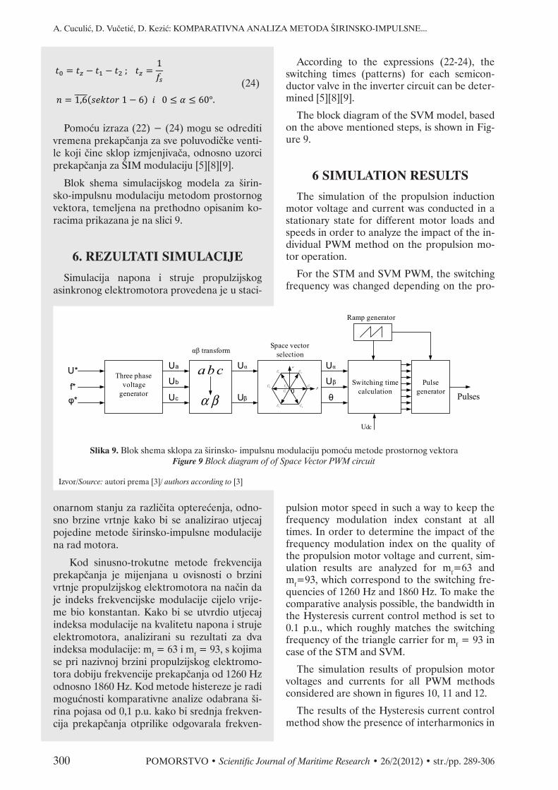
Pomoću izraza (22) − (24) mogu se odrediti vremena prekapčanja za sve poluvodičke venti-le koji čine sklop izmjenjivača, odnosno uzorci prekapčanja za ŠIM modulaciju [5][8][9].
Blok shema simulacijskog modela za širin-sko-impulsnu modulaciju metodom prostornog vektora, temeljena na prethodno opisanim ko-racima prikazana je na slici 9.
6. REZULTATI SIMULACIJE
Simulacija napona i struje propulzijskog asinkronog elektromotora provedena je u staci-
Three phasevoltage
generator
Ua
f*φ*
Ub
Uc α β
abc α
β1U
2U
3U
4U
5U
6U
7U
0U
0
Uα
Uβ
U* Uα
Uβ
θ
Switching time calculation
Pulsegenerator
Ramp generator
Pulses
Udc
αβ transformSpace vector
selection
Slika 9. Blok shema sklopa za širinsko- impulsnu modulaciju pomoću metode prostornog vektoraFigure 9 Block diagram of of Space Vector PWM circuit
Izvor/Source: autori prema [3]/ authors according to [3]
According to the expressions (22-24), the switching times (patterns) for each semicon-ductor valve in the inverter circuit can be deter-mined [5][8][9].
The block diagram of the SVM model, based on the above mentioned steps, is shown in Fig-ure 9.
6 SIMULATION RESULTS
The simulation of the propulsion induction motor voltage and current was conducted in a stationary state for different motor loads and speeds in order to analyze the impact of the in-dividual PWM method on the propulsion mo-tor operation.
For the STM and SVM PWM, the switching frequency was changed depending on the pro-
pulsion motor speed in such a way to keep the frequency modulation index constant at all times. In order to determine the impact of the frequency modulation index on the quality of the propulsion motor voltage and current, sim-ulation results are analyzed for mf=63 and mf=93, which correspond to the switching fre-quencies of 1260 Hz and 1860 Hz. To make the comparative analysis possible, the bandwidth in the Hysteresis current control method is set to 0.1 p.u., which roughly matches the switching frequency of the triangle carrier for mf = 93 in case of the STM and SVM.
The simulation results of propulsion motor voltages and currents for all PWM methods considered are shown in figures 10, 11 and 12.
The results of the Hysteresis current control method show the presence of interharmonics in
onarnom stanju za različita opterećenja, odno-sno brzine vrtnje kako bi se analizirao utjecaj pojedine metode širinsko-impulsne modulacije na rad motora.
Kod sinusno-trokutne metode frekvencija prekapčanja je mijenjana u ovisnosti o brzini vrtnje propulzijskog elektromotora na način da je indeks frekvencijske modulacije cijelo vrije-me bio konstantan. Kako bi se utvrdio utjecaj indeksa modulacije na kvalitetu napona i struje elektromotora, analizirani su rezultati za dva indeksa modulacije: mf = 63 i mf = 93, s kojima se pri nazivnoj brzini propulzijskog elektromo-tora dobiju frekvencije prekapčanja od 1260 Hz odnosno 1860 Hz. Kod metode histereze je radi mogućnosti komparativne analize odabrana ši-rina pojasa od 0,1 p.u. kako bi srednja frekven-cija prekapčanja otprilike odgovarala frekven-

A. Cuculić, D. Vučetić, D. Kezić: COMPARATIVE ANALYSIS OF THE PULSE WIDTH MODULATION METHODS...
POMORSTVO • Scientific Journal of Maritime Research • 26/2(2012) • str./pp. 289-306 301
ciji trokutnog nositelja za indeks modulacije mf = 93.
Rezultati simulacije koji prikazuju napone i struje propulzijskog elektromotora za sve tri modulacijske metode prikazani su na slikama 10, 11 i 12. Kod metode histereze prisutni su međuharmonici u struji tereta zbog toga što frekvencija širinsko-impulsne modulacije tije-kom periode izlaznog napona nije konstantna (varira zbog širine pojasa histereze), što je ujed-no i jedan od glavnih nedostataka ove tehnike.
Kod sinusno-trokutne metode i metode mo-dulacije prostornog vektora može se vidjeti po-javljivanje najnižih harmonika u blizini harmo-nika čiji red odgovara indeksu frekvencijske modulacije mf. Također se može vidjeti da se amplitude harmonika ne smanjuju povećanjem njihovog reda, kao npr. kod ispravljača, već po-stoji svojevrsno grupiranje harmonika oko više-kratnika indeksa modulacije, stoga se može go-voriti o pojasevima harmonika. S obzirom da se prvi značajni harmonici mogu očekivati u blizi-ni harmonika čiji red odgovara indeksu modu-
0 0,01 0,02 0,03 0,04 0,05
-1
-0.5
0
0.5
1
t(s)
Udc
[p.
u.]
Propulsion motor line voltage (Uab)
0 0,01 0,02 0,03 0,04 0,05-1
-0.5
0
0.5
1
t(s)
Ia [
p.u.
]
Propulsion motor line current (Ia)
0 500 1000 1500 2000 2500 30000
10
20
30
40
50
60
Frequency (Hz)
Fundamental (20Hz); THDu = 168.81%
Mag
(%
of
Fund
amen
tal)
0 500 1000 1500 2000 2500 30000
0.5
1
1.5
2
2.5
Fundamental (20Hz); THDi= 9.86%
Frequency (Hz)
Mag
(%
of
Fund
amen
tal)
Slika 10. Struja, napon, THDi i THDu propulzijskog elektromotora pri nazivnom opterećenju (metoda histereze s HB = 0,1 p.u.)
Figure 10 Propulsion motor current, voltage, THDi and THDu at nominal load (Hysteresis band PWM with HB=0.1 p.u.)
Izvor/Source: autori/authors
the load current, caused by a variable frequency of the pulse width modulation during the peri-od of output voltage (it varies due to the hyster-esis bandwidth). This is a main drawback of this modulation technique.
When the STM and SVM methods are used, it can be seen that the lowest harmonics appear close to the harmonic, the order of which cor-responds to frequency modulation index mf. In addition, the amplitudes of harmonics are not reduced with the increase of the harmonics or-der, but there is a sort of harmonics grouping (harmonic bands) around multiples of the fre-quency modulation index. Since the first signifi-cant harmonics can be expected near the har-monics whose order corresponds to mf, then, with a sufficiently high switching frequency, the first harmonics occur at relatively high frequen-cies and they are easily filtered by the propul-sion motor inductance.
The comparison of voltage and current har-monic distortions (THDu and THDi) depend-ing on the propulsion motor speed is shown in Figures 13 and 14.

A. Cuculić, D. Vučetić, D. Kezić: KOMPARATIVNA ANALIZA METODA ŠIRINSKO-IMPULSNE...
302 POMORSTVO • Scientific Journal of Maritime Research • 26/2(2012) • str./pp. 289-306
0 0,01 0,02 0,03 0,04 0,05
-1
-0.5
0
0.5
1
t (s)
Udc
[p.
u.]
Propulsion motor line voltage (Uab)
0 0,01 0,02 0,03 0,04 0,05-1
-0.5
0
0.5
1
Propulsion motor line current (ia)
t (s)
Ia [
p.u.
]
0 500 1000 1500 2000 2500 30000
5
10
15
20
25
30
Fundamental (20Hz), mf=63 , THDu= 68.66%
Frequency (Hz)
Mag
(%
of
Fund
amen
tal)
0 500 1000 1500 2000 2500 30000
1
2
3
4
5
6
Fundamental (20Hz), mf=63 , THDi= 9.14%
Frequency (Hz)
Mag
(%
of
Fund
amen
tal)
Slika 11. Struja, napon, THDi i THDu propulzijskog elektromotora pri nazivnom opterećenju (Sinusno-trokutna metoda, mf = 63)
Figure 11 Propulsion motor current, voltage, THDi and THDu at nominal load (Sine-triangle PWM, mf = 63)
Izvor/Source: autori/authors
lacije mf, tada se uz dovoljno veliku frekvenciju prekapčanja najveći harmonici napona javljaju na relativno visokim frekvencijama, što indukti-vitet propulzijskog elektromotora lako filtrira.
Usporedba ukupnih harmoničkih izobličenja struje i napona u ovisnosti o brzini vrtnje pro-pulzijskog elektromotora prikazana je na slika-ma 13 i 14.
Kod metode histereze javljaju se povećana harmonička izobličenja struje propulzijskog elektromotora pri malom broju okretaja, što se moglo i očekivati s obzirom da je širina pojasa histereze držana konstantnom u svim režimima rada. Kada je širina pojasa histereze u simulacij-skom modelu smanjena s 0,1 p.u. na 0,05 p.u., THDi se u području niskih okretaja smanjio na 8,14%, ali se istovremeno frekvencija prekapča-nja povećala za otprilike 2,5 puta. Dakle, za bo-lje rezultate trebalo bi koristiti neku od metoda adaptivnog upravljanja širinom pojasa histereze koja zahtijeva složene matematičke izračune, te složeniju i skuplju izvedbu [10] [11].
With the hysteresis current control PWM method, the increased harmonic distortions are present at lower motor speeds, as might be ex-pected, because the HB was kept constant throughout the entire speed range. When the HB in the simulation model has been reduced from 0.1 to 0.05 p.u., the THDi at low speeds decreased to 8.14%, but at the same time the switching frequency was increased by approxi-mately 2.5 times. Therefore, to obtain the ac-ceptable harmonic distortion, more complex and computational demanding methods of the adaptive HB control should be used [10] [11].
For the STM and SVM methods, the THDu of the propulsion motor line voltage does not change with the load if the frequency modula-tion index mf is constant, because, in this case, the voltage waveform and thus the harmonic spectrum are nearly identical throughout the entire speed range. Increasing the mf by in-creasing the switching frequency does not im-prove the THDu significantly, which was ex-pected considering the waveform of such a

A. Cuculić, D. Vučetić, D. Kezić: COMPARATIVE ANALYSIS OF THE PULSE WIDTH MODULATION METHODS...
POMORSTVO • Scientific Journal of Maritime Research • 26/2(2012) • str./pp. 289-306 303
Ukupno harmoničko izobličenje izlaznog na-pona pretvarača kod sinusno-trokutne metode i metode modulacije prostornog vektora ne mije-nja se s opterećenjem ako se zadržava isti indeks frekventne modulacije jer je u tom slučaju valni oblik, a prema tome i harmonički spektar napo-na približno isti. Povećanjem indeksa frekventne modulacije, a to znači i frekvencije prekapčanja ventila ne poboljšava se bitno THDu koji kod obje metode ostaje vrlo visok što je i razumljivo ako se uzme u obzir valni oblik tako modulira-nog napona (sl. 11, 12). Pri tome treba naglasiti da je THDu napona uvjerljivo najbolji kod me-tode modulacije prostornog vektora, a uvjerljivo najlošiji kod metode histereze.
Razlike, međutim, dolaze do punog izražaja kada se usporede ukupna harmonička izobliče-nja struje prikazana na slici 13. Očekivano, THDi je najmanji kod metode modulacije pro-stornog vektora, a najveći kod metode histere-ze. Od sve tri promatrane metode, metoda mo-dulacije prostornog vektora daje i najveću
0 0,01 0,02 0,03 0,04 0,05
-1
-0.5
0
0.5
1
t (s)
Udc
[p
.u]
Propulsion motor line voltage (Uab)
0 0,01 0,02 0,03 0,04 0,05-1
-0.5
0
0.5
1
Propulsion motor line current (Ia)
t (s)
Ia [
p.u.
]
0 500 1000 1500 2000 2500 30000
5
10
15
20
Fundamental (20Hz), mf=63 , THDu= 52.80%
Frequency (Hz)
Mag
(%
of
Fund
amen
tal)
0 500 1000 1500 2000 2500 30000
1
2
3
4
Fundamental (20Hz), mf=63 , THDi= 7.2%
Frequency (Hz)
Mag
(%
of
Fund
amen
tal)
Slika 12. Struja, napon, THDi i THDu propulzijskog elektromotora pri nazivnom opterećenju (Metoda modulacije prostornog vektora, mf = 63)
Figure 10 Propulsion motor current, voltage, THDi and THDu at nominal load (Space vector PWM, mf =63)
Izvor/Source: autori/authors
modulated voltage. It should be noted that the propulsion motor voltage THDu is arguably the best when the SVM method is used and the worst one with the hysteresis current control method.
Differences, however, become more intense when the THDi of the propulsion motor cur-rents are compared (Figure 13). As expected, the lowest THDi is with the SVM and the high-est with the hysteresis current control method. In addition, the SVM method provides the highest effective DC link voltage utilization of all three methods [5] [8].
It is important to note that the index of the frequency modulation has a very large impact on the THDi, so that, e.g., with the STM and mf=93 better results are obtained than with the SVM and mf=63.
Increasing the switching frequency signifi-cantly reduces the current THDi and thus the vibration and copper losses of the propulsion motor, but also increases the switching and pro-

A. Cuculić, D. Vučetić, D. Kezić: KOMPARATIVNA ANALIZA METODA ŠIRINSKO-IMPULSNE...
304 POMORSTVO • Scientific Journal of Maritime Research • 26/2(2012) • str./pp. 289-306
efektivnu iskoristivost napona istosmjernog međukruga [5] [8].
Važno je, međutim, uočiti da indeks frekven-tne modulacije ima vrlo velik utjecaj na THDi,
0
20
40
60
80
100
120
4
6
8
10
12
14
16
10 20 30 40 50 60 70 80 90 100
% o
f nom
inal
pro
puls
ion
mot
or lo
ad
Prop
ulsi
on m
otor
TH
Di
(%)
% of nominal propulsion motor speed (rpm)
Hyst. (HB=10A) STM (mf=63) STM (mf=93)
SVM (mf=63) SVM (mf=93) Load
Slika 13. Usporedba ukupnih harmoničkih izobličenja struje kod simuliranih metoda modulacije uz različite indekse frekventne modulacije u ovisnosti o brzini vrtnje propulzijskog elektromotora
Figure 13 Comparison of total current harmonic distortion between simulated methods with different frequency modulation indexes as a function propulsion motor speed
Izvor/Source: autori/authors
0
20
40
60
80
100
120
45
50
55
60
65
70
75
80
85
10 20 30 40 50 60 70 80 90 100 % o
f nom
inal
pro
puls
ion
mot
or lo
ad
Prop
ulsi
on m
otor
TH
Du
(%)
% of nominal propulsion motor speed (rpm)
Hyst. (HB=10A) STM (mf=63) STM (mf=93)
SVM (mf=63) SVM (mf=93) Load
Slika 14. Usporedba ukupnih harmoničkih izobličenja napona kod simuliranih metoda modulacije uz različite indekse frekventne modulacije u ovisnosti o brzini vrtnje propulzijskog elektromotora
Figure 14 Comparison of total voltage harmonic distortion between simulated methods with different frequency modulation indexes as a function propulsion motor speed
Izvor/Source: autori/authors
pulsion motor iron losses. Therefore, an opti-mal modulation frequency should be selected so that the total loss of the entire system, in-cluding the electrical propulsion electric motor, is minimal.

A. Cuculić, D. Vučetić, D. Kezić: COMPARATIVE ANALYSIS OF THE PULSE WIDTH MODULATION METHODS...
POMORSTVO • Scientific Journal of Maritime Research • 26/2(2012) • str./pp. 289-306 305
tako da se npr. s mf = 93 i trokutno-sinusnom metodom dobiju bolji rezultati, nego s mf = 63 i metodom modulacije prostornog vektora.
Povećanjem frekvencije prekapčanja bitno se, dakle smanjuje ukupno harmoničko izobli-čenje struje (THDi), a samim time i vibracije i gubici u bakru namotaja propulzijskog elektro-motora. No povećanje frekvencije prekapčanja za sobom povlači povećanje gubitaka prekapča-nja na poluvodičkim ventilima izmjenjivača, ali i gubitaka u željezu motora. Optimalnu fre-kvenciju, odnosno indeks frekventne modulaci-je treba stoga odabrati tako da je ukupni gubi-tak cijelog sustava uključujući i propulzijski elektromotor minimalan.
7. ZAKLJUČAKIzvršena komparativna analiza utjecaja me-
toda širinsko-impulsne modulacije na kvalitetu struje i napona propulzijskog elektromotora pokazala je da se najveća izobličenja struje i na-pona javljaju kod metode histereze, posebice pri niskim okretajima kada se koristi konstan-tna širina pojasa. Ukoliko se pri smanjenom broju okretaja elektromotora na maksimalnoj prihvatljivoj frekvenciji prekapčanja ukupna harmonička izobličenja mogu držati dovoljno malima, zbog svoje jednostavne i jeftine imple-mentacije, kao i posebno male osjetljivosti na valovitost i izobličenja ulaznog napona, metoda histereze može predstavljati prihvatljivo, ali uglavnom ne i najbolje rješenje za potrebe elek-trične propulzije broda. Donekle zadovoljava-jući rezultati korištenjem ove metode mogu se postići samo primjenom složenih adaptivnih al-goritama za kontrolu širine pojasa, čime se na-vedene prednosti jeftine implementacije gube.
Kod približno istih indeksa modulacije sinu-sno-trokutna metoda i metoda modulacije pro-stornog vektora daju puno bolji izlazni napon u kojem su zbog konstantne frekvencije prekap-čanja tijekom periode međuharmonici potisnu-ti, dok se prvi viši harmonici i njihovi bočni po-jasevi javljaju tek pri višim frekvencijama, oko reda koji odgovara indeksu frekvencijske mo-dulacije. Povećanje frekvencije prekapčanja ne mijenja značajno THDu motora, ali se zato THDi osjetno smanjuje.
Gledajući na kvalitetu napona i struje pro-pulzijskog elektromotora, pri približno istim frekvencijama prekapčanja poluvodičkih venti-la u izmjenjivaču, metoda modulacije prostor-
7 CONCLUSION
A comparative analysis of the propulsion motor voltage and current with respect to the applied PWM method has shown that the greatest harmonic distortions occur with the hysteresis current control method. This is espe-cially noticeable at low speeds when the con-stant hysteresis bandwidth is used. If the THDu and THDi can be kept constant at low speeds, this method may represent an acceptable, but, generally, not the best solution for the ship electrical propulsion applications, mainly due to its simple, low cost implementation and low sensitivity to input voltage ripple. Fairly satis-factory results with the hysteresis current con-trol PWM can only be achieved by applying complex adaptive algorithms to control the hys-teresis bandwidth, but the above mentioned benefits are then lost.
With approximately the same switching fre-quencies, the STM and SVM methods give much better output voltage, where the interhar-monics are suppressed due to the constant switching frequency during the period. The first harmonics group appear at higher frequencies around the harmonic order that corresponds to the modulation frequency. Increasing the switching frequency does not change the THDu significantly, but the THDi is greatly reduced.
The analysis of the simulation results show that, at approximately the same switching fre-quencies, the SVM PWM method gives by far the best results. Adding the highest effective usage of the DC link voltage and excellent dy-namic properties, it may be concluded that the SVM PWM method represents the best choice for the control of the propulsion PWM fre-quency converters.

A. Cuculić, D. Vučetić, D. Kezić: KOMPARATIVNA ANALIZA METODA ŠIRINSKO-IMPULSNE...
306 POMORSTVO • Scientific Journal of Maritime Research • 26/2(2012) • str./pp. 289-306
nog vektora daje uvjerljivo najbolje rezultate. Doda li se tome i najveća efektivna iskoristivost napona istosmjernog međukruga, te odlične di-namičke osobine, može se zaključiti da metoda modulacije prostornog vektora predstavlja naj-bolji izbor kod upravljanja propulzijskim ŠIM pretvaračima.
LITERATURA / REFERENCES
[1] Vlahinić, I., D.Vučetić, Perspektiva razvoja statičkih pretvarača frekvencije u sustavu električne propulzije broda, Pomorstvo, 15(2001), str. 117-131.
[2] Ong, C.M., Dynamic simulation of electric machinery using MATLAB/SIMULINK, Prentice Hall Inc., 1997. [3] Hydro-Quebec, SimPowerSystems™ R2012b User’s Guide, MathWorks, 2012. [4] Vasudevan, K., Rao, G.S., Rao P.S., Electrical Machines I, Indian Institute of technology-Madras. On line at:
http://nptel.iitm.ac.in/courses/IIT-MADRAS/Electrical_Machines_I/, October 2012. [5] Bose, B.K., Modern Power Electronics and AC drives, Prentice Hall Inc., 2005. [6] Arilaga, J., N. R. Watson, Power System Harmonics, Wiley, 2003. [7] Rashid, M. H., Power Electronics Handbook, Academic Press, 2001. [8] Vintoh, K.K., et al., Simulation and comparison of SPWM and SVPWM control for three phase inverter, ARPN
Journal of Engineering and Applied Sciences, 5 (2010), 7, str. 61-74. [9] Zhou, K., D. Wang, Relationship Between Space-Vector Modulation and Three-Phase Carrier-Based PWM: A
Comprehensive Analysis, IEEE Transactions on Industrial Electronics, 48 (2002), 1, str.186-196. [10] Bose, B.K., An Adaptive Hysteresis-band Current Control Technique of a Voltage-fed PWM Inverter for Machine
Drives System, IEEE Trans. on Industrial Electronics, 37 (1990), 5. [11] Jena, S., B. C. Babu, S. R. S. Mohaptara, Comparative Study Between Adaptive Hysteresis and SVPWM Current
Control for Grid-connected Inverter System, Proceeding of the IEEE Student’s Technology Symposium, 2011.