Embed Size (px)
Citation preview
2004.3Ver. 1.0
Di1611/Di2011SERVICE MANUAL
© 2004 KONICA MINOLTA BUSINESS TECHNOLOGIES, INC.
Printed in Japan4034-7991-1104030700
Use of this manual should be strictly supervised toavoid disclosure of confidential information.
FIELD SERVICE
2004.3 Ver.1.0
Di1611/D
i2011F
IELD
SE
RV
ICE
Read carefully the Safety and Important Warning Items described below to understand them before doing service work.
Because of possible hazards to an inexperienced person servicing this product as well as the risk of damage to the product, Konica Minolta Business Technologies, INC. (hereafter called the KMBT) strongly recommends that all servicing be performed only by KMBT-trained service technicians.Changes may have been made to this product to improve its performance after this Service Manual was printed. Accordingly, KMBT does not warrant, either explicitly or implicitly, that the information contained in this Service Manual is complete and accurate.The user of this Service Manual must assume all risks of personal injury and/or damage to the product while servicing the product for which this Service Manual is intended.Therefore, this Service Manual must be carefully read before doing service work both in the course of technical training and even after that, for performing maintenance and control of the product properly.Keep this Service Manual also for future service.
In this Service Manual, each of three expressions “ DANGER”, “ WARNING”, and
“ CAUTION” is defined as follows together with a symbol mark to be used in a limited meaning. When servicing the product, the relevant works (disassembling, reassembling, adjustment,
SAFETY AND IMPORTANT WARNING ITEMS
IMPORTANT NOTICE
DESCRIPTION ITEMS FOR DANGER,WARNING AND CAUTION
P-1
repair, maintenance, etc.) need to be conducted with utmost care.
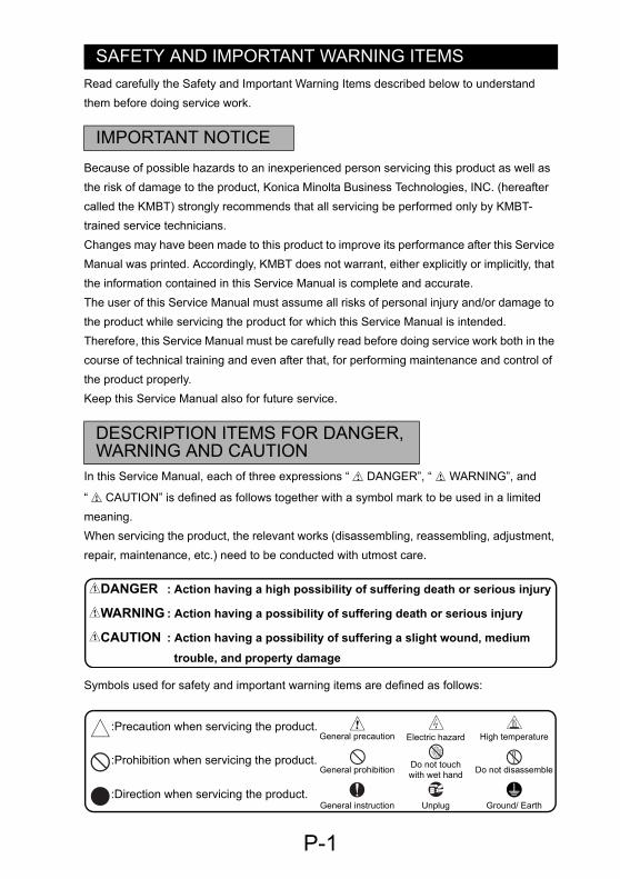
Symbols used for safety and important warning items are defined as follows:
DANGER : Action having a high possibility of suffering death or serious injury
WARNING : Action having a possibility of suffering death or serious injury
CAUTION : Action having a possibility of suffering a slight wound, medium trouble, and property damage
:Precaution when servicing the product.General precaution Electric hazard High temperature
:Prohibition when servicing the product.General prohibition Do not touch
with wet hand Do not disassemble
:Direction when servicing the product.General instruction Unplug Ground/ Earth
SAFETY WARNINGS
1. MODIFICATIONS NOT AUTHORIZED BYKONICA MINOLTA BUSINESS TECHNOLOGIES, INC.
Konica Minolta brand products are renowned for their high reliability. This reliability is achieved through high-quality design and a solid service network.Product design is a highly complicated and delicate process where numerous mechanical, physical, and electrical aspects have to be taken into consideration, with the aim of arriving at proper tolerances and safety factors. For this reason, unauthorized modifications involve a high risk of degradation in performance and safety. Such modifications are therefore strictly prohibited. the points listed below are not exhaustive, but they illustrate the reason-ing behind this policy.
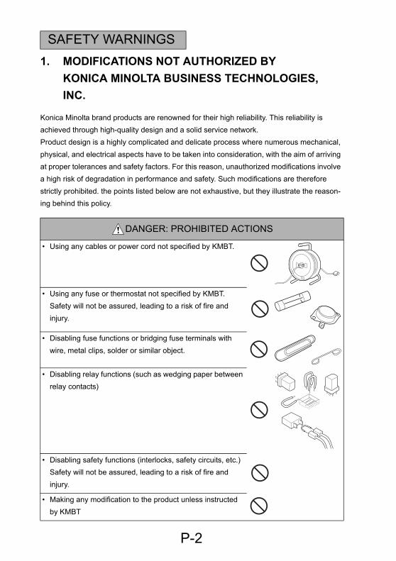
DANGER: PROHIBITED ACTIONS
• Using any cables or power cord not specified by KMBT.
• Using any fuse or thermostat not specified by KMBT. Safety will not be assured, leading to a risk of fire and injury.
• Disabling fuse functions or bridging fuse terminals with wire, metal clips, solder or similar object.
P-2
• Disabling relay functions (such as wedging paper between relay contacts)
• Disabling safety functions (interlocks, safety circuits, etc.) Safety will not be assured, leading to a risk of fire and injury.
• Making any modification to the product unless instructed by KMBT
2. CHECKPOINTS WHEN PERFORMING ON-SITE SER-VICE
Konica Minolta brand products are extensively tested before shipping, to ensure that all applicable safety standards are met, in order to protect the customer and customer engi-neer (hereafter called the CE) from the risk of injury. However, in daily use, any electrical equipment may be subject to parts wear and eventual failure. In order to maintain safety and reliability, the CE must perform regular safety checks.
1. Power Supply
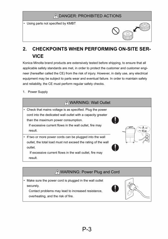
• Using parts not specified by KMBT
WARNING: Wall Outlet
• Check that mains voltage is as specified. Plug the power cord into the dedicated wall outlet with a capacity greater than the maximum power consumption.
If excessive current flows in the wall outlet, fire may result.
• If two or more power cords can be plugged into the wall outlet, the total load must not exceed the rating of the wall outlet.
DANGER: PROHIBITED ACTIONS
P-3
If excessive current flows in the wall outlet, fire may result.
WARNING: Power Plug and Cord
• Make sure the power cord is plugged in the wall outlet securely.
Contact problems may lead to increased resistance, overheating, and the risk of fire.
WARNING: Power Plug and Cord
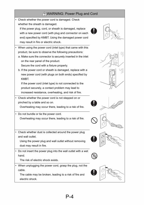
• Check whether the power cord is damaged. Check whether the sheath is damaged.
If the power plug, cord, or sheath is damaged, replace with a new power cord (with plug and connector on each end) specified by KMBT. Using the damaged power cord may result in fire or electric shock.
• When using the power cord (inlet type) that came with this product, be sure to observe the following precautions: a. Make sure the connector is securely inserted in the inlet
on the rear panel of the product.Secure the cord with a fixture properly.
b. If the power cord or sheath is damaged, replace with a new power cord (with plugs on both ends) specified by KMBT. If the power cord (inlet type) is not connected to the product securely, a contact problem may lead to increased resistance, overheating, and risk of fire.
• Check whether the power cord is not stepped on or pinched by a table and so on.
Overheating may occur there, leading to a risk of fire.
• Do not bundle or tie the power cord. Overheating may occur there, leading to a risk of fire.
P-4
• Check whether dust is collected around the power plug and wall outlet.
Using the power plug and wall outlet without removing dust may result in fire.
• Do not insert the power plug into the wall outlet with a wet hand.
The risk of electric shock exists.
• When unplugging the power cord, grasp the plug, not the cable.
The cable may be broken, leading to a risk of fire and electric shock.
2. Installation Requirements
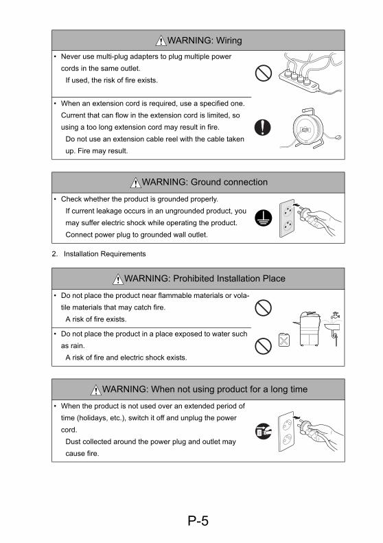
WARNING: Wiring
• Never use multi-plug adapters to plug multiple power cords in the same outlet.
If used, the risk of fire exists.
• When an extension cord is required, use a specified one.Current that can flow in the extension cord is limited, so using a too long extension cord may result in fire.
Do not use an extension cable reel with the cable taken up. Fire may result.
WARNING: Ground connection
• Check whether the product is grounded properly.If current leakage occurs in an ungrounded product, you may suffer electric shock while operating the product. Connect power plug to grounded wall outlet.
WARNING: Prohibited Installation Place
• Do not place the product near flammable materials or vola-tile materials that may catch fire.
A risk of fire exists.
• Do not place the product in a place exposed to water such
P-5
as rain.A risk of fire and electric shock exists.
WARNING: When not using product for a long time
• When the product is not used over an extended period of time (holidays, etc.), switch it off and unplug the power cord.
Dust collected around the power plug and outlet may cause fire.

CAUTION: Ventilation
• The product generates ozone gas during operation, but it will not be harmful to the human body.
If a bad smell of ozone is present in the following cases, ventilate the room.
a. When the product is used in a poorly ventilated roomb. When taking a lot of copiesc. When using multiple products at the same time
CAUTION: Fixing
• Be sure to lock the caster stoppers.In the case of an earthquake and so on, the product may slide, leading to a injury.
CAUTION: Inspection before Servicing
• Before conducting an inspection, read all relevant docu-mentation (service manual, technical notices, etc.) and proceed with the inspection following the prescribed pro-cedure, using only the prescribed tools. Do not make any adjustment not described in the documentation.
If the prescribed procedure or tool is not used, the prod-uct may break and a risk of injury or fire exists.
• Before conducting an inspection, be sure to disconnect the power plugs from the product and options.
P-6
When the power plug is inserted in the wall outlet, some units are still powered even if the POWER switch is turned OFF. A risk of electric shock exists.
• The area around the fixing unit is hot.You may get burnt.
WARNING: Work Performed with the product Powered
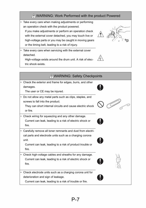
• Take every care when making adjustments or performing an operation check with the product powered.
If you make adjustments or perform an operation check with the external cover detached, you may touch live or high-voltage parts or you may be caught in moving gears or the timing belt, leading to a risk of injury.
• Take every care when servicing with the external cover detached.
High-voltage exists around the drum unit. A risk of elec-tric shock exists.
WARNING: Safety Checkpoints
• Check the exterior and frame for edges, burrs, and other damages.
The user or CE may be injured.
• Do not allow any metal parts such as clips, staples, and screws to fall into the product.
They can short internal circuits and cause electric shock or fire.
• Check wiring for squeezing and any other damage. Current can leak, leading to a risk of electric shock or fire.
P-7
• Carefully remove all toner remnants and dust from electri-cal parts and electrode units such as a charging corona unit.
Current can leak, leading to a risk of product trouble or fire.
• Check high-voltage cables and sheaths for any damage.Current can leak, leading to a risk of electric shock or fire.
• Check electrode units such as a charging corona unit for deterioration and sign of leakage.
Current can leak, leading to a risk of trouble or fire.
WARNING: Safety Checkpoints
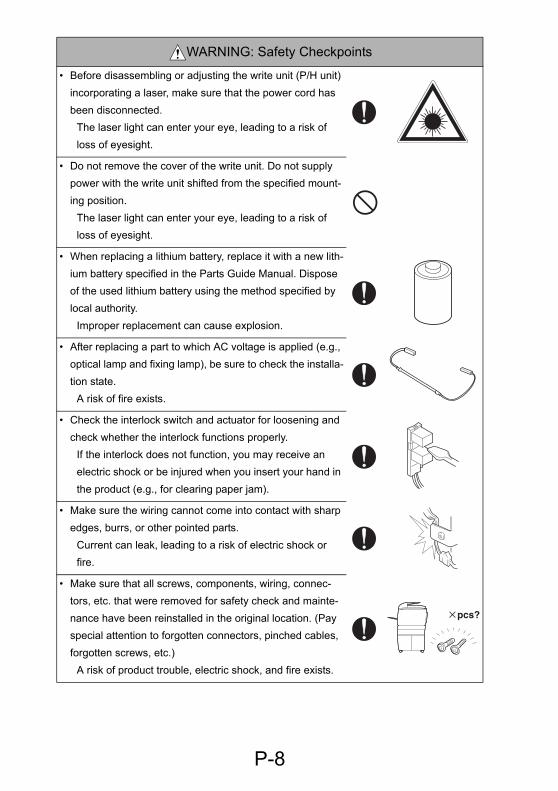
• Before disassembling or adjusting the write unit (P/H unit) incorporating a laser, make sure that the power cord has been disconnected.
The laser light can enter your eye, leading to a risk of loss of eyesight.
• Do not remove the cover of the write unit. Do not supply power with the write unit shifted from the specified mount-ing position.
The laser light can enter your eye, leading to a risk of loss of eyesight.
• When replacing a lithium battery, replace it with a new lith-ium battery specified in the Parts Guide Manual. Dispose of the used lithium battery using the method specified by local authority.
Improper replacement can cause explosion.
• After replacing a part to which AC voltage is applied (e.g., optical lamp and fixing lamp), be sure to check the installa-tion state.
A risk of fire exists.
• Check the interlock switch and actuator for loosening and check whether the interlock functions properly.
If the interlock does not function, you may receive an electric shock or be injured when you insert your hand in the product (e.g., for clearing paper jam).
P-8
• Make sure the wiring cannot come into contact with sharp edges, burrs, or other pointed parts.
Current can leak, leading to a risk of electric shock or fire.
• Make sure that all screws, components, wiring, connec-tors, etc. that were removed for safety check and mainte-nance have been reinstalled in the original location. (Pay special attention to forgotten connectors, pinched cables, forgotten screws, etc.)
A risk of product trouble, electric shock, and fire exists.
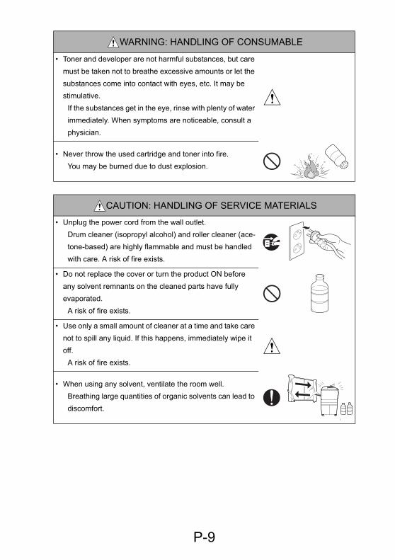
WARNING: HANDLING OF CONSUMABLE
• Toner and developer are not harmful substances, but care must be taken not to breathe excessive amounts or let the substances come into contact with eyes, etc. It may be stimulative.
If the substances get in the eye, rinse with plenty of water immediately. When symptoms are noticeable, consult a physician.
• Never throw the used cartridge and toner into fire.You may be burned due to dust explosion.
CAUTION: HANDLING OF SERVICE MATERIALS
• Unplug the power cord from the wall outlet.Drum cleaner (isopropyl alcohol) and roller cleaner (ace-tone-based) are highly flammable and must be handled with care. A risk of fire exists.
• Do not replace the cover or turn the product ON before any solvent remnants on the cleaned parts have fully evaporated.
A risk of fire exists.
• Use only a small amount of cleaner at a time and take care not to spill any liquid. If this happens, immediately wipe it
P-9
off.A risk of fire exists.
• When using any solvent, ventilate the room well.Breathing large quantities of organic solvents can lead to discomfort.
3. MEASURES TO TAKE IN CASE OF AN ACCIDENT
1. If an accident has occurred, the distributor who has been notified first must immediately take emergency measures to provide relief to affected persons and to prevent further damage.
2. If a report of a serious accident has been received from a customer, an on-site evalua-tion must be carried out quickly and KMBT must be notified.
3. To determine the cause of the accident, conditions and materials must be recorded through direct on-site checks, in accordance with instructions issued by KMBT.
4. CONCLUSION
1. Safety of users and customer engineers depends highly on accurate maintenance and administration. Therefore, safety can be maintained by the appropriate daily service work conducted by the customer engineer.
2. When performing service, each product on the site must be tested for safety. The cus-tomer engineer must verify the safety of parts and ensure appropriate management of the equipment.
P-10

INDEX
ADJUSTING/SETTING
MAINTENANCE
TROUBLESHOOTING
CONTENTS1. MODIFICATIONS NOT AUTHORIZED BY
KONICA MINOLTA BUSINESS TECHNOLOGIES, INC. ................................ P-22. CHECKPOINTS WHEN PERFORMING ON-SITE SERVICE ......................... P-33. MEASURES TO TAKE IN CASE OF AN ACCIDENT ...................................... P-104. CONCLUSION ................................................................................................. P-10
MAINTENANCE1. SAFETY INFORMATION ................................................................................. 1-1
1.1 Laser Safety ............................................................................................. 1-11.2 Internal Laser Radiation ........................................................................... 1-11.3 Laser Safety Label ................................................................................... 1-41.4 Laser Caution Label ................................................................................. 1-41.5 Precautions for Handling the Laser Equipment ........................................ 1-5
2. OTHER PRECAUTIONS .................................................................................. 1-53. PRECAUTIONS FOR DISASSEMBLY/ADJUSTMENTS ................................. 1-6
3.1 Parts That Must Not be Touched ............................................................. 1-63.1.1 Red Painted Screws ...................................................................... 1-63.1.2 Variable resistors on board ............................................................ 1-63.1.3 Other Screws not Marked with Red Paint ...................................... 1-6
4. SERVICE TOOLS ............................................................................................ 1-74.1 Jigs and Tools .......................................................................................... 1-7
5. MAINTENANCE SCHEDULE .......................................................................... 1-85.1 PM Parts List ............................................................................................ 1-85.2 Guidelines for Life-time Expected Values by Unit .................................... 1-95.3 Replacement and Cleaning of Parts ........................................................ 1-10
5.3.1 Paper Take-up/Transport Section ................................................. 1-10(1) Removal of the Paper Separator Roller Assy and Paper Take-Up
Roller. ..................................................................................... 1-10(2) Cleaning of the Paper Separator Roller ................................. 1-11(3) Cleaning of the Paper Take-Up Roller ................................... 1-11(4) Cleaning of the Upper/Lower Synchronizing Rollers ............. 1-11
i
(5) Removal of the Paper Dust Remover Assy ........................... 1-12(6) Cleaning of the Paper Dust Remover .................................... 1-12(7) Cleaning of the Bypass Transport Roller/Roll ........................ 1-12
5.3.2 IR Section ...................................................................................... 1-13(1) Cleaning of the Original Glass and Original Scanning Glass . 1-13(2) Cleaning of Mirrors ................................................................. 1-13(3) Cleaning of the Lens .............................................................. 1-14(4) Cleaning of the CCD Sensor .................................................. 1-14(5) Cleaning of the Scanner Rails/Bushings ................................ 1-15
5.3.3 PH Section ..................................................................................... 1-15(1) Cleaning of the PH Window ................................................... 1-15
5.3.4 Imaging Unit (IU) ........................................................................... 1-16(1) Removal of the Imaging Unit (IU) ........................................... 1-16(2) Disassembly of the IU ............................................................ 1-16(3) Removal of the PC Drum ....................................................... 1-18(4) Removal of the Ozone Filter .................................................. 1-18(5) Removal of the PC Drum Charge Corona Assy ..................... 1-19
(6) Removal of the Cleaning Blade ............................................. 1-19
(7) Cleaning of the PC Drum Paper Separator Fingers ............... 1-19(8) Cleaning of the Ds Collars ..................................................... 1-20(9) Cleaning of the Developer Scattering Prevention Plate ......... 1-20(10) Replacement of the Developer .............................................. 1-20(11) Cleaning of the Pre-Image Transfer Guide Plate ................... 1-21(12) Replacement of the ATDC Sensor ......................................... 1-21(13) Application of Toner ............................................................... 1-225.3.5 IMAGE TRANSFER SECTION ...................................................... 1-24(1) Removal of the Image Transfer Roller Assy .......................... 1-24(2) Cleaning of the Pre-Image Transfer Lower Guide Plate ........ 1-24(3) Cleaning of the Charge Neutralizing Plate ............................. 1-24
5.3.6 FUSING SECTION ........................................................................ 1-25(1) Removal of the Fusing Unit .................................................... 1-25
6. MISCELLANEOUS PARTS .............................................................................. 1-266.1 Disassembly and Reassembly ................................................................. 1-26
6.1.1 Identification and Removal Procedures of Doors, Covers, and Exterior Parts 1-26(1) Copier .................................................................................... 1-26
6.1.2 Removal of Circuit Boards and Other Electric Components .......... 1-28(1) Removal of the Master Board (PWB-A) ................................. 1-29(2) Removal of the Control Board (PWB-C/C) ............................. 1-30(3) Removal of the High Voltage Unit (HV1) ............................... 1-31(4) Removal of the Power Supply Unit (PU1) .............................. 1-32(5) Removal of the Paper Size Detecting Board (PWB-I) ............ 1-33(6) Removal of the Heater Relay Board (PWB-RY): 200 V area only 1-
34(7) Removal of the Pre-image Transfer Board (PWB-R2) ........... 1-34
6.1.3 Removal of Units ........................................................................... 1-35(1) Removal of the Manual Bypass ............................................. 1-35(2) Removal of the Manual Bypass (Duplex Unit): Di2011 Only . 1-35(3) Removal of the Toner Hopper Unit ........................................ 1-35(4) Removal of the PH Unit ......................................................... 1-36(5) Disassembly of the Fusing Unit ............................................. 1-37
ii
6.1.4 Disassembly of the IR Section ....................................................... 1-40(1) Removal of the CCD Unit ....................................................... 1-40(2) Installation of the CCD Unit .................................................... 1-41(3) Removal of the Scanner, Exposure Lamp, and Inverter Board (PU2)
1-41(4) Removal of the Scanner Motor .............................................. 1-43(5) Removal of the Scanner Drive Cables ................................... 1-44(6) Winding of the Scanner Drive Cables .................................... 1-47
6.1.5 Disassembly of the Engine Section ............................................... 1-52(1) Removal of the Main Motor .................................................... 1-52(2) Removal of the Power Unit Cooling Fan Motor ...................... 1-52(3) Removal of the Fusing Cooling Fan Motor ............................ 1-53(4) Removal of the Paper Size Sensor Assy ............................... 1-54(5) Removal of the Fusing Unit Interlock Switch ......................... 1-55(6) Removal of the Inch/Metric Sensor/1 Assy (3rd area Only) ... 1-57(7) Removal of the Flickerless Resistor (Only for 200 V area of Di1611)
1-57
6.2 Remounting of the EEPROM (U16) ......................................................... 1-58
6.3 Installation of the Key Counter ................................................................. 1-597. UPGRADING THE FIRMWARE ....................................................................... 1-617.1 Upgrading the Copier Firmware (PWB-C/C) ............................................ 1-61
7.1.1 Installing the Driver ........................................................................ 1-61(1) Plug and Play Installation of the GDI Printer/TWAIN Driver .. 1-61
7.1.2 Procedure for Upgrading the GDI Firmware .................................. 1-637.1.3 Procedure when Upgrading the Firmware has failed .................... 1-65
ADJUSTING/SETTING1. HOW TO USE THE ADJUSTMENT SECTION ................................................ 2-1
1.1 Composition ............................................................................................. 2-11.1.1 Checking before starting work ....................................................... 2-11.1.2 Checkpoints when conducting on-site service ............................... 2-1
3. UTILITY MODE ................................................................................................ 2-53.1 Utility Mode Function Tree ....................................................................... 2-53.2 Utility Mode Setting Procedure ................................................................. 2-73.3 Setting in the Utility Mode ........................................................................ 2-7
3.3.1 MACHINE SETTING ..................................................................... 2-7(1) AUTO PANEL RESET ........................................................... 2-7(2) ENERGY SAVE MODE ......................................................... 2-7(3) AUTO SHUT OFF .................................................................. 2-7(4) DENSITY (ADF) ..................................................................... 2-8(5) DENSITY (BOOK) .................................................................. 2-8(6) PRINT DENSITY .................................................................... 2-8(7) LCD CONTRAST ................................................................... 2-8(8) LANGUAGE ........................................................................... 2-8
3.3.2 PAPER SOURCE SETUP ............................................................. 2-9(1) INCH/METRIC ....................................................................... 2-9(2) TRAY1 PAPER ...................................................................... 2-9(3) PAPER TYPE ........................................................................ 2-9
3.3.3 USER MANAGEMENT .................................................................. 2-10(1) DRUM DEHUMIDIFY ............................................................. 2-10
iii
(2) TONER REPLENISHER ........................................................ 2-103.3.4 ADMIN. MANAGEMENT ............................................................... 2-11
(1) AUTO SHUT OFF .................................................................. 2-11(2) COPY TRACK ........................................................................ 2-11
3.3.5 COPY SETTING 1 ......................................................................... 2-14(1) PAPER PRIORITY ................................................................. 2-14(2) DENSITY PRIORITY ............................................................. 2-14(3) DENSITY LEVEL (A) ............................................................. 2-14(4) DENSITY LEVEL (M) ............................................................. 2-14(5) BINDING POS. ...................................................................... 2-14(6) MARGIN SETTING ................................................................ 2-14(7) ERASE SETTING .................................................................. 2-15(8) SMALL ORIGINAL ................................................................. 2-15
3.3.6 COPY SETTING 2 ......................................................................... 2-15(1) MIXED ORIGINAL ................................................................. 2-15(2) COPY PRIORITY ................................................................... 2-15(3) OUTPUT PRIORITY .............................................................. 2-15(4) 4IN1 COPY ORDER .............................................................. 2-16
(5) CRISSCROSS MODE ........................................................... 2-16
(6) DUPLEX COPY ..................................................................... 2-164. SERVICE MODE .............................................................................................. 2-174.1 Service Mode Function Tree .................................................................... 2-174.2 Service Mode Function Setting Procedure ............................................... 2-204.3 Setting in the Service Mode ..................................................................... 2-21
4.3.1 SERVICE’S CHOICE ..................................................................... 2-21(1) SHIPMENT DESTINATION ................................................... 2-21(2) MAINTENANCE COUNTER .................................................. 2-22(3) IU LIFE STOP MODE ............................................................ 2-22(4) ID ADJUST ............................................................................ 2-22(5) VG ADJUST ........................................................................... 2-23(6) FUSER TEMP. Ad (PLAIN) .................................................... 2-23(7) FUSER TEMP. Ad (THICK) ................................................... 2-24(8) FUSER TEMP. Ad (OHP) ...................................................... 2-25(9) LEADING EDGE ERASE ....................................................... 2-26(11) TRAILING EDGE ERASE ...................................................... 2-27(12) VERTICAL EDGE ERASE ..................................................... 2-28(13) LOOP ADJUST (TRAY1) ....................................................... 2-29(14) LOOP ADJUST (TRAY2 TO TRAY5) .................................... 2-29(15) LOOP ADJUST (DUPLEX): Di2011 Only .............................. 2-30(16) LOOP ADJUST (BYPASS) .................................................... 2-30(17) FLS PAPER SIZE .................................................................. 2-31(18) CCD APS SIZE ...................................................................... 2-31(19) GDI TIMEOUT ....................................................................... 2-31
4.3.2 ADJUST ......................................................................................... 2-32(1) PRN MAIN REGIST ............................................................... 2-32(2) PRN SUB REGIST ................................................................. 2-33(3) CCD MAIN ZOOM ................................................................. 2-34(4) CCD SUB ZOOM ................................................................... 2-35(5) CCD MAIN REGIST ............................................................... 2-36(6) CCD SUB REGIST ................................................................ 2-37(7) ADF SUB ZOOM .................................................................... 2-38(8) ADF MAIN REGIST ............................................................... 2-38
iv
(9) ADF SUB REGIST1 ............................................................... 2-38(10) ADF SUB REGIST2 ............................................................... 2-39(11) ADF REG. LOOP1 ................................................................. 2-39(12) ADF REG. LOOP2 ................................................................. 2-39(13) ATDC GAIN ........................................................................... 2-39(14) MODEL SETTING .................................................................. 2-40
4.3.3 COUNTER ..................................................................................... 2-40(1) TOTAL COUNTER ................................................................. 2-40(5) SIZE COUNTER .................................................................... 2-40(6) PM COUNTER ....................................................................... 2-40(7) MAINTENANCE COUNTER .................................................. 2-41(8) SUPPLIES LIFE COUNT. ...................................................... 2-41(9) APPLICATION COUNTER .................................................... 2-41(10) SCAN COUNTER .................................................................. 2-41(11) PAPER SIZE COUNTER ....................................................... 2-42(12) MISFEED COUNTER ............................................................ 2-42(13) TROUBLE COUNTER ........................................................... 2-43
4.3.4 DISPLAY ....................................................................................... 2-44
(1) TONER DENSITY LEVEL ...................................................... 2-44(2) PROCESS CONTROL ........................................................... 2-44(3) MAIN F/W VER. (PWB-C/C) .................................................. 2-45(4) ENGINE F/W VER. (PWB-A) ................................................. 2-45(5) PCL F/W VER. ....................................................................... 2-45(6) NIC F/W VER. ........................................................................ 2-45(7) ADF F/W VER. ....................................................................... 2-45(8) MAIN RAM SIZE .................................................................... 2-45(9) PCL RAM SIZE ...................................................................... 2-45(10) SERIAL NO. ........................................................................... 2-45(11) CUSTOMER ID ...................................................................... 2-464.3.5 FUNCTION .................................................................................... 2-46(1) PAPER FEED TEST .............................................................. 2-46(2) PROCESS CHECK ................................................................ 2-46(3) ATDC AUTO ADJUST ........................................................... 2-46(4) PRINT TEST PATTERN ........................................................ 2-47(5) ADF FEED TEST ................................................................... 2-47(6) COPY ADF GLASS AREA ..................................................... 2-47(7) CCD MOVE TO HOME .......................................................... 2-48(8) SCAN TEST ........................................................................... 2-48(9) ADF WIDTH ADJ. (MAX) ....................................................... 2-48(10) ADF WIDTH ADJ. (MIN) ........................................................ 2-48(11) ADF SENSOR ADJUST ......................................................... 2-48
4.3.6 ADMIN. REGISTRATION .............................................................. 2-494.3.7 FIXED ZOOM CHANGE ................................................................ 2-50
(1) Japan ..................................................................................... 2-50(2) Metric ..................................................................................... 2-50(3) Inch ........................................................................................ 2-50(4) China ...................................................................................... 2-50(5) Latin America (Metric) ............................................................ 2-51(6) Latin America (Inch) ............................................................... 2-51(7) OEM1 US ............................................................................... 2-51
4.3.8 FACTORY TEST ........................................................................... 2-51
v
(1) PANEL BUZZER TEST .......................................................... 2-51(2) RAM TEST ............................................................................. 2-51
4.3.9 CLEAR DATA ................................................................................ 2-52(1) MEMORY CLEAR .................................................................. 2-52(2) PM COUNTER ....................................................................... 2-52(3) MAINTENANCE COUNTER .................................................. 2-52(4) SUPPLIES LIFE COUNT. ...................................................... 2-52(5) APPLICATION COUNTER .................................................... 2-52(6) SCAN COUNTER .................................................................. 2-52(7) PAPER SIZE COUNTER ....................................................... 2-53(8) MISFEED COUNTER ............................................................ 2-53(9) TROUBLE COUNTER ........................................................... 2-53(10) ADF BACKUP CLEAR (Di2011 Only) .................................... 2-53
4.3.10SECURITY .................................................................................... 2-53(1) TOTAL COUNTER COUNT ................................................... 2-53(2) SIZE COUNTER COUNT ...................................................... 2-54(3) PLUG-IN COUNTER COPY .................................................. 2-54
(4) MACHINE COUNTER ............................................................ 2-54
5. MECHANICAL ADJUSTMENTS ...................................................................... 2-555.1 Adjustment of the Position of the Scanner and 2nd/3rd Mirrors Carriage 2-555.2 CCD Unit Position Adjustment ................................................................. 2-575.3 Adjustment of the Gap between the Doctor Blade and Sleeve Roller (Db
Adjustment) .............................................................................................. 2-585.4 Manual Bypass (for the optional AD-17) CD Registration Adjustment ..... 2-60
TROUBLESHOOTING1. INTRODUCTION .............................................................................................. 3-1
1.1 Electrical Components Check Procedure ................................................ 3-11.1.1 Sensor ........................................................................................... 3-11.1.2 Switch ............................................................................................ 3-21.1.3 Solenoid ......................................................................................... 3-21.1.4 Clutch ............................................................................................ 3-21.1.5 Motor ............................................................................................. 3-3
2. MISFEEDS ....................................................................................................... 3-42.1 Initial Checks ............................................................................................ 3-42.2 Paper Misfeed Detection .......................................................................... 3-4
2.2.1 Outline ........................................................................................... 3-42.3 Misfeed Display ........................................................................................ 3-52.4 Misfeed-Detecting Sensor Layout ............................................................ 3-62.5 Misfeed Detection Timing/Troubleshooting Procedures .......................... 3-7
2.5.1 Misfeed at the Paper Feed Tray/1 Paper Take-up Section ........... 3-72.5.2 Misfeed at the Manual Bypass Paper Take-up Section ................. 3-82.5.3 Misfeed at the Multiple Bypass Paper Take-up Section (When the
optional Multiple Bypass MB-6 is mounted) 3-92.5.4 Misfeed at the Paper Feed Unit Paper Take-up/Vertical Transport Section
(When the optional Paper Feed Unit PF-126 is mounted) 3-102.5.5 Misfeed at the Paper Separating Section ...................................... 3-112.5.6 Misfeed at the Fusing/Exit Section ................................................ 3-122.5.7 Misfeed at the Document Take-up Section (When the optional Automatic
vi
Document Feeder AF-12 is mounted) 3-132.5.8 Misfeed at the Document Transport Section (When the optional
Automatic Document Feeder AF-12 is mounted) 3-142.5.9 Misfeed at the Document Exit Section (When the optional Automatic
Document Feeder AF-12 is mounted) 3-153. MALFUNCTIONS ............................................................................................. 3-16
3.1 List of Malfunction Codes ......................................................................... 3-163.2 Resetting Procedure by Malfunction Code ............................................... 3-203.3 Malfunction Detection Timing and Troubleshooting Procedure ............... 3-21
(1) C0000 Main Motor malfunction .............................................. 3-21(2) C0044 ADF Cooling Fan Failure
(When the optional Duplexing Document Feeder AFR-19 is mount-ed) .......................................................................................... 3-22
(3) C0045 Fusing Cooling Fan Motor Malfunction ....................... 3-23(4) C004E Power Supply Cooling Fan Motor Malfunction ........... 3-24(5) C0070 Toner Replenishing Motor Malfunction ....................... 3-25(6) C0210 Abnormal Image Transfer Voltage ............................. 3-26
(7) C0500 Warm-up Failure
C0501 Warm-up Failure 2 (Di2011 Only)C0510 Fusing Failure (Abnormally Low Fusing Temperature)C0511 Fusing Failure (Abnormally Low Fusing Temperature 2) (Di2011 Only)C0520 Fusing Failure (Abnormally High Fusing Temperature)C0521 Fusing Failure (Abnormally High Fusing Temperature 2) (Di2011 Only) ......................................................................... 3-27(8) C0650 Faulty Scanner Home Position Sensor ...................... 3-30(9) C0F32 Faulty ATDC Sensor
C0F33 Improperly Adjusted ATDC Sensor ............................ 3-31(10) C1038 Engine Connection Failure ......................................... 3-32(11) C1200 Faulty ASIC/Memory .................................................. 3-33(12) C1300 Polygon Motor Malfunction
C13F0 Faulty HSYNC ............................................................ 3-34(13) C133B Communication with Option Error
C133D ROM Check Error ...................................................... 3-35(14) C1468 Faulty EEPROM ......................................................... 3-35(15) C14A3 IR Fluorescent Lamp Fault ......................................... 3-36
3.4 Miscellaneous Errors ................................................................................ 3-373.4.1 Flash ROM Error ........................................................................... 3-37
3.5 Power Source-Related Malfunctions ........................................................ 3-38(1) The copier does not turn ON. ................................................. 3-38
4. IMAGE FAILURE ............................................................................................. 3-404.1 Image Failure Troubleshooting ................................................................ 3-404.2 Initial Checks ............................................................................................ 3-404.3 Identification of the Faulty System ........................................................... 3-414.4 Troubleshooting Procedures by Image Failure ........................................ 3-42
4.4.1 Image Reading Section: Blank copy .............................................. 3-424.4.2 Image Reading Section: black copy .............................................. 3-434.4.3 Image Reading Section: Low image density ................................. 3-444.4.4 Image Reading Section: Foggy background or rough image ........ 3-454.4.5 Image Reading Section: Black streaks or bands ........................... 3-46
vii
4.4.6 Image Reading Section: Black spots ............................................. 3-474.4.7 Image Reading Section: Blank streaks or bands ........................... 3-484.4.8 Image Reading Section: Uneven image density ............................ 3-494.4.9 Image Reading Section: Gradation reproduction failure ................ 3-504.4.10 Image Reading Section: Periodically uneven image ..................... 3-514.4.11 Image Reading Section: Moire ...................................................... 3-524.4.12Printer Section: Blank copy ........................................................... 3-534.4.13Printer Section: Black copy ............................................................ 3-544.4.14Printer Section: Low image density ............................................... 3-554.4.15Printer Section: Foggy background or rough image ...................... 3-564.4.16Printer Section: Black streaks or bands ......................................... 3-574.4.17Printer Section: Black spots ........................................................... 3-584.4.18Printer Section: Blank streaks or bands ........................................ 3-594.4.19Printer Section: Void areas ............................................................ 3-604.4.20Printer Section: Smear on back ..................................................... 3-614.4.21Printer Section: Uneven image density ......................................... 3-62

4.4.22Printer Section: Gradation reproduction failure ............................. 3-63
4.4.23Printer Section: Periodically uneven image ................................... 3-64viii

MAINTENANCE
19971
Di1611/Di2011 FIELD SERVICE Ver.1.0 Mar. 2004 MAINTENANCE
1. SAFETY INFORMATION1.1 Laser Safety• This is a digital machine certified as a class 1 laser product. There is no possibility of
danger from a laser, provided the machine is serviced according to the instruction in this manual.
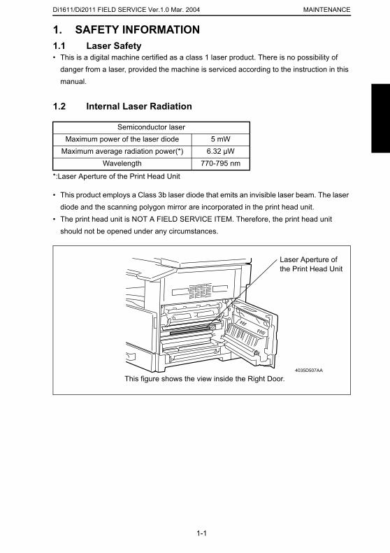
1.2 Internal Laser Radiation
*:Laser Aperture of the Print Head Unit
• This product employs a Class 3b laser diode that emits an invisible laser beam. The laser diode and the scanning polygon mirror are incorporated in the print head unit.
• The print head unit is NOT A FIELD SERVICE ITEM. Therefore, the print head unit should not be opened under any circumstances.
Semiconductor laserMaximum power of the laser diode 5 mW
Maximum average radiation power(*) 6.32 µWWavelength 770-795 nm
Laser Aperture ofthe Print Head Unit
1-1
4035D507AA
This figure shows the view inside the Right Door.
Di1611/Di2011 FIELD SERVICE Ver.1.0 Mar. 2004MAINTENANCE
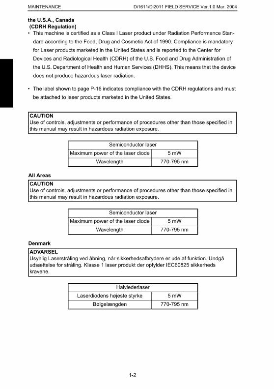
the U.S.A., Canada (CDRH Regulation)
• This machine is certified as a Class I Laser product under Radiation Performance Stan-dard according to the Food, Drug and Cosmetic Act of 1990. Compliance is mandatory for Laser products marketed in the United States and is reported to the Center for Devices and Radiological Health (CDRH) of the U.S. Food and Drug Administration of the U.S. Department of Health and Human Services (DHHS). This means that the device does not produce hazardous laser radiation.
• The label shown to page P-16 indicates compliance with the CDRH regulations and must be attached to laser products marketed in the United States.
All Areas
Denmark
CAUTIONUse of controls, adjustments or performance of procedures other than those specified in this manual may result in hazardous radiation exposure.
Semiconductor laserMaximum power of the laser diode 5 mW
Wavelength 770-795 nm
CAUTIONUse of controls, adjustments or performance of procedures other than those specified in this manual may result in hazardous radiation exposure.
Semiconductor laserMaximum power of the laser diode 5 mW
Wavelength 770-795 nm
1-2
ADVARSELUsynlig Laserstråling ved åbning, når sikkerhedsafbrydere er ude af funktion. Undgå udsættelse for stråling. Klasse 1 laser produkt der opfylder IEC60825 sikkerheds kravene.
HalvlederlaserLaserdiodens højeste styrke 5 mW
Bølgelængden 770-795 nm
Di1611/Di2011 FIELD SERVICE Ver.1.0 Mar. 2004 MAINTENANCE
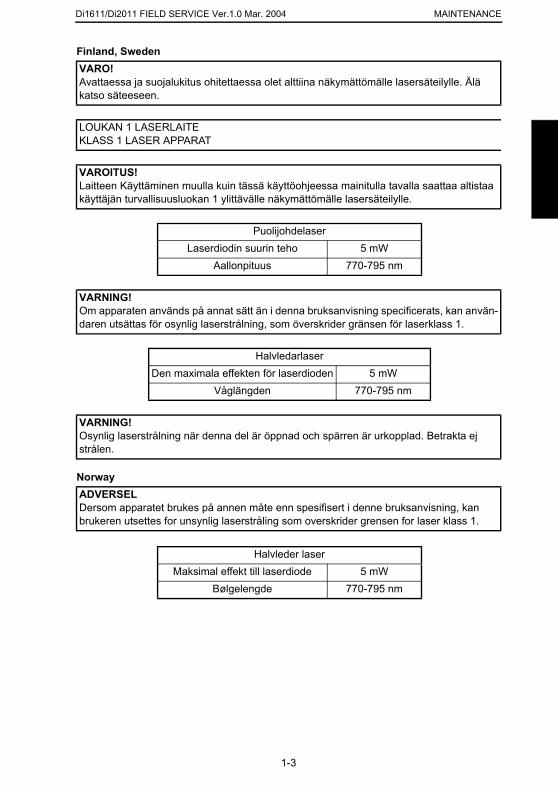
Finland, Sweden
Norway
VARO!Avattaessa ja suojalukitus ohitettaessa olet alttiina näkymättömälle lasersäteilylle. Älä katso säteeseen.
LOUKAN 1 LASERLAITEKLASS 1 LASER APPARAT
VAROITUS!Laitteen Käyttäminen muulla kuin tässä käyttöohjeessa mainitulla tavalla saattaa altistaa käyttäjän turvallisuusluokan 1 ylittävälle näkymättömälle lasersäteilylle.
PuolijohdelaserLaserdiodin suurin teho 5 mW
Aallonpituus 770-795 nm
VARNING!Om apparaten används på annat sätt än i denna bruksanvisning specificerats, kan använ-daren utsättas för osynlig laserstrålning, som överskrider gränsen för laserklass 1.
HalvledarlaserDen maximala effekten för laserdioden 5 mW
Våglängden 770-795 nm
VARNING!Osynlig laserstrålning när denna del är öppnad och spärren är urkopplad. Betrakta ej strålen.
1-3
ADVERSELDersom apparatet brukes på annen måte enn spesifisert i denne bruksanvisning, kan brukeren utsettes for unsynlig laserstråling som overskrider grensen for laser klass 1.
Halvleder laserMaksimal effekt till laserdiode 5 mW
Bølgelengde 770-795 nm
Di1611/Di2011 FIELD SERVICE Ver.1.0 Mar. 2004MAINTENANCE
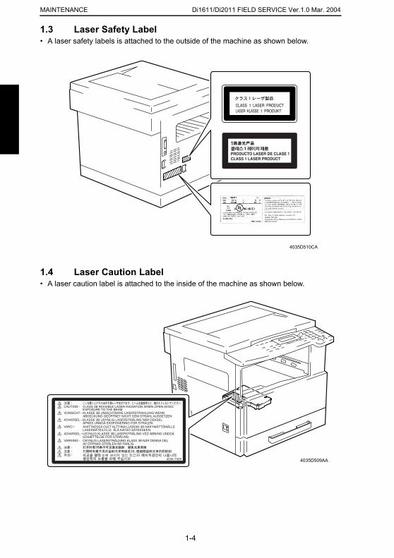
1.3 Laser Safety Label• A laser safety labels is attached to the outside of the machine as shown below.
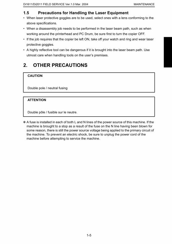
1.4 Laser Caution Label• A laser caution label is attached to the inside of the machine as shown below.
4035D510CA
1-4
4035D509AA
Di1611/Di2011 FIELD SERVICE Ver.1.0 Mar. 2004 MAINTENANCE
1.5 Precautions for Handling the Laser Equipment• When laser protective goggles are to be used, select ones with a lens conforming to the
above specifications.• When a disassembly job needs to be performed in the laser beam path, such as when
working around the printerhead and PC Drum, be sure first to turn the copier OFF.• If the job requires that the copier be left ON, take off your watch and ring and wear laser
protective goggles.• A highly reflective tool can be dangerous if it is brought into the laser beam path. Use
utmost care when handling tools on the user’s premises.
2. OTHER PRECAUTIONS
✽ A fuse is installed in each of both L and N lines of the power source of this machine. If the machine is brought to a stop as a result of the fuse on the N line having been blown for some reason, there is still the power source voltage being applied to the primary circuit of the machine. To prevent an electric shock, be sure to unplug the power cord of the machine before attempting to service the machine.
CAUTION
Double pole / neutral fusing
ATTENTION
Double pôle / fusible sur le neutre.
1-5
Di1611/Di2011 FIELD SERVICE Ver.1.0 Mar. 2004MAINTENANCE
3. PRECAUTIONS FOR DISASSEMBLY/ADJUST-
MENTS3.1 Parts That Must Not be Touched
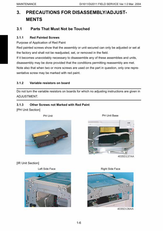
3.1.1 Red Painted ScrewsPurpose of Application of Red PaintRed painted screws show that the assembly or unit secured can only be adjusted or set at the factory and shall not be readjusted, set, or removed in the field.If it becomes unavoidably necessary to disassemble any of these assemblies and units, disassembly may be done provided that the conditions permitting reassembly are met. Note also that when two or more screws are used on the part in question, only one repre-sentative screw may be marked with red paint.
3.1.2 Variable resistors on board
Do not turn the variable resistors on boards for which no adjusting instructions are given in ADJUSTMENT.
3.1.3 Other Screws not Marked with Red Paint[PH Unit Section]
PH Unit PH Unit Base
1-6
[IR Unit Section]
4035D137AA
4035D136AA
Right Side FaceLeft Side Face
Di1611/Di2011 FIELD SERVICE Ver.1.0 Mar. 2004 MAINTENANCE
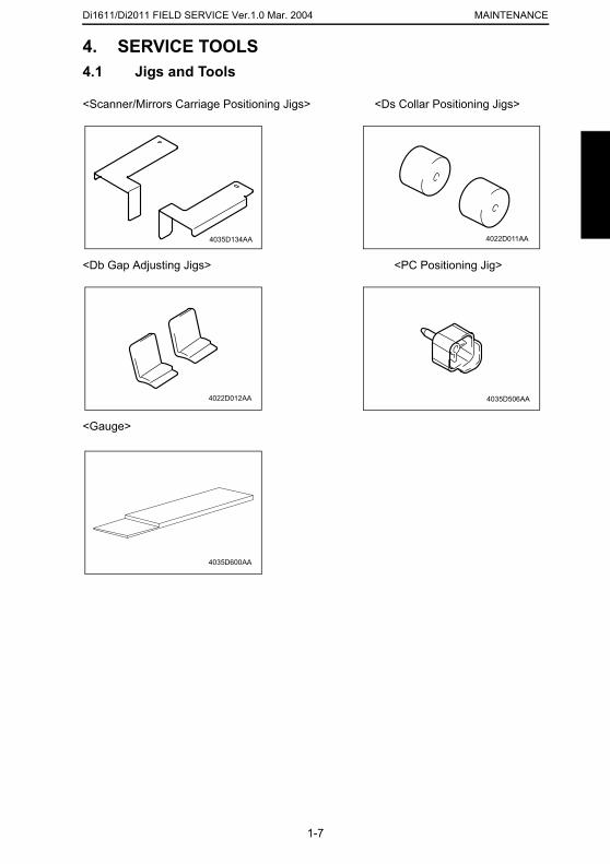
4. SERVICE TOOLS4.1 Jigs and Tools
<Scanner/Mirrors Carriage Positioning Jigs> <Ds Collar Positioning Jigs>
<Db Gap Adjusting Jigs> <PC Positioning Jig>
<Gauge>
4035D134AA 4022D011AA
4022D012AA 4035D506AA
1-7
4035D600AA
Di1611/Di2011 FIELD SERVICE Ver.1.0 Mar. 2004MAINTENANCE
5. MAINTENANCE SCHEDULE
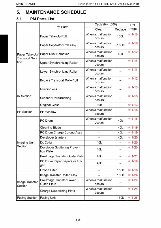
5.1 PM Parts ListPM PartsCycle (K=1,000) Ref.
PageClean Replace
Paper Take-Up/Transport Sec-tion
Paper Take-Up Roll When a malfunction occurs 150k ☞ 1-10
Paper Separator Roll Assy When a malfunction occurs 150k ☞ 1-10
Paper Dust Remover When a malfunction occurs 40k ☞ 1-12
Upper Synchronizing Roller When a malfunction occurs – ☞ 1-11
Lower Synchronizing Roller When a malfunction occurs – ☞ 1-11
Bypass Transport Roller/roll When a malfunction occurs – ☞ 1-12
IR Section
Mirrors/Lens When a malfunction occurs – ☞ 1-13
Scanner Rails/Bushing When a malfunction occurs – ☞ 1-15
Original Glass 80k – ☞ 1-13
PH Section PH Window When a malfunction occurs – ☞ 1-15
Imaging Unit Section
PC Drum When a malfunction occurs 40k ☞ 1-16
Cleaning Blade – 40k ☞ 1-19PC Drum Charge Corona Assy – 40k ☞ 1-19Developer (starter) – 40k ☞ 1-20Ds Collar 40k – ☞ 1-20
1-8
Developer Scattering Preven-tion Plate 40k – ☞ 1-20
Pre-Image Transfer Guide Plate 40k – ☞ 1-21PC Drum Paper Separator Fin-ger 40k – ☞ 1-19
Ozone Filter – 150k ☞ 1-18
Image Transfer Section
Image Transfer Roller Assy – 150k ☞ 1-24Pre-Image Transfer Lower Guide Plate
When a malfunction occurs – ☞ 1-24
Charge Neutralizing Plate When a malfunction occurs – ☞ 1-24
Fusing Section Fusing Unit – 150k ☞ 1-25
Di1611/Di2011 FIELD SERVICE Ver.1.0 Mar. 2004 MAINTENANCE
NOTES• The contents of the maintenance schedule are subject to change without notice.• For part numbers, see Parts Manual and Parts Modification Notice.• Both for the copier and options, check the PM counter values for performing the service
procedures.☞ 2-22
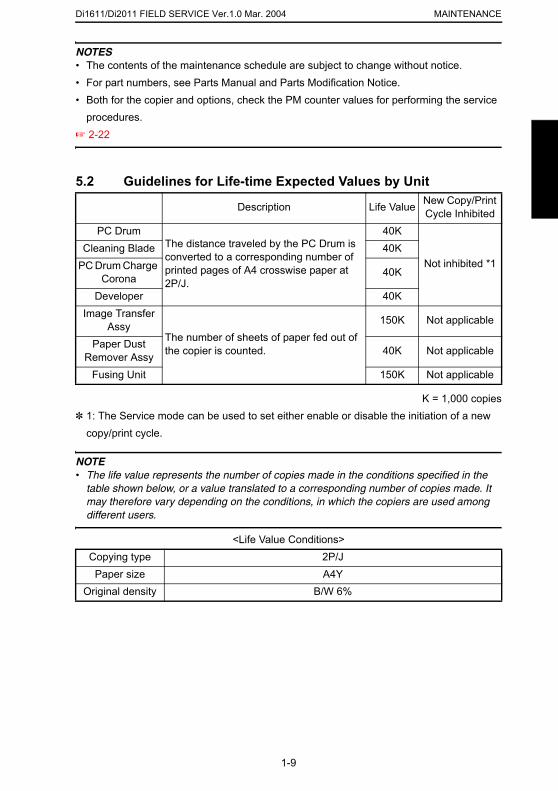
5.2 Guidelines for Life-time Expected Values by Unit
K = 1,000 copies✽ 1: The Service mode can be used to set either enable or disable the initiation of a new
copy/print cycle.
NOTE• The life value represents the number of copies made in the conditions specified in the
table shown below, or a value translated to a corresponding number of copies made. It
Description Life Value New Copy/Print Cycle Inhibited
PC DrumThe distance traveled by the PC Drum is converted to a corresponding number of printed pages of A4 crosswise paper at 2P/J.
40K
Not inhibited *1Cleaning Blade 40K
PC Drum Charge Corona 40K
Developer 40KImage Transfer
AssyThe number of sheets of paper fed out of the copier is counted.
150K Not applicable
Paper Dust Remover Assy 40K Not applicable
Fusing Unit 150K Not applicable
1-9
may therefore vary depending on the conditions, in which the copiers are used among different users.
<Life Value Conditions>Copying type 2P/J
Paper size A4YOriginal density B/W 6%
Di1611/Di2011 FIELD SERVICE Ver.1.0 Mar. 2004MAINTENANCE
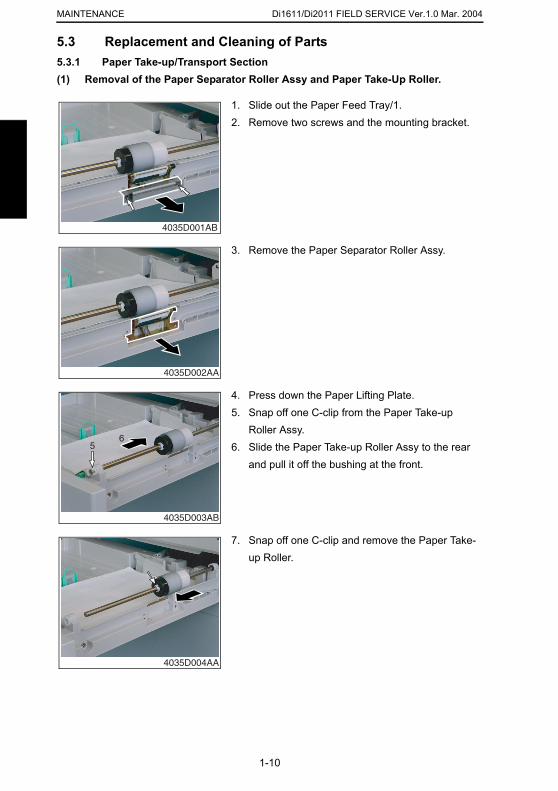
5.3 Replacement and Cleaning of Parts
5.3.1 Paper Take-up/Transport Section(1) Removal of the Paper Separator Roller Assy and Paper Take-Up Roller.1. Slide out the Paper Feed Tray/1.2. Remove two screws and the mounting bracket.
4035D001AB
3. Remove the Paper Separator Roller Assy.
4035D002AA
4. Press down the Paper Lifting Plate.5. Snap off one C-clip from the Paper Take-up
Roller Assy.6. Slide the Paper Take-up Roller Assy to the rear
and pull it off the bushing at the front.
56
1-10
4035D003AB
7. Snap off one C-clip and remove the Paper Take-up Roller.
4035D004AA
Di1611/Di2011 FIELD SERVICE Ver.1.0 Mar. 2004 MAINTENANCE
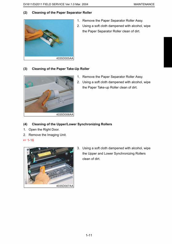
(2) Cleaning of the Paper Separator Roller
(3) Cleaning of the Paper Take-Up Roller
(4) Cleaning of the Upper/Lower Synchronizing Rollers1. Open the Right Door.2. Remove the Imaging Unit.☞ 1-16
1. Remove the Paper Separator Roller Assy.2. Using a soft cloth dampened with alcohol, wipe
the Paper Separator Roller clean of dirt.
4035D005AA
1. Remove the Paper Separator Roller Assy.2. Using a soft cloth dampened with alcohol, wipe
the Paper Take-up Roller clean of dirt.
4035D006AA
3. Using a soft cloth dampened with alcohol, wipe
1-11
the Upper and Lower Synchronizing Rollers clean of dirt.
4035D007AA
Di1611/Di2011 FIELD SERVICE Ver.1.0 Mar. 2004MAINTENANCE
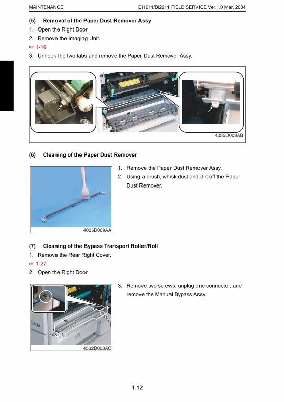
(5) Removal of the Paper Dust Remover Assy1. Open the Right Door.
2. Remove the Imaging Unit.☞ 1-163. Unhook the two tabs and remove the Paper Dust Remover Assy.(6) Cleaning of the Paper Dust Remover
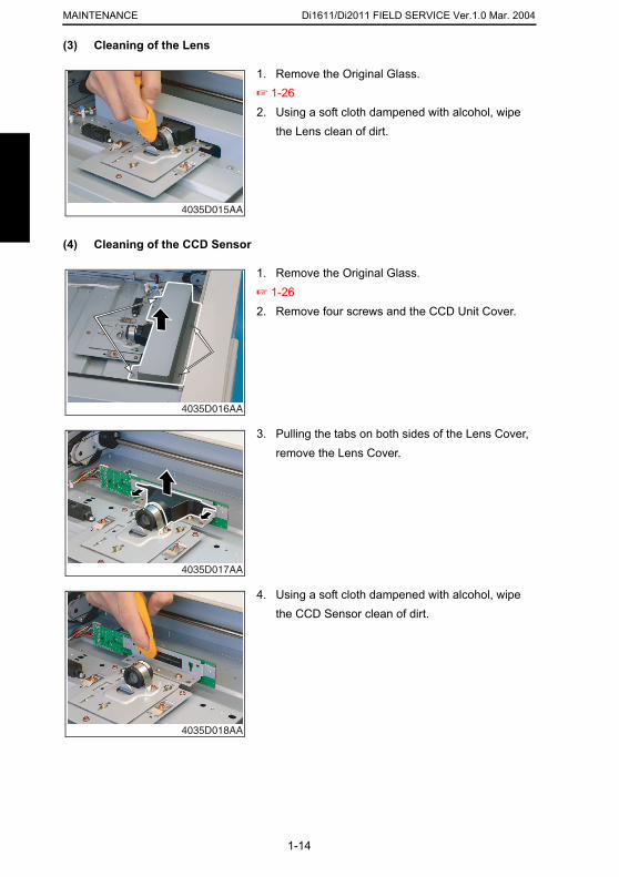
(7) Cleaning of the Bypass Transport Roller/Roll1. Remove the Rear Right Cover.
4035D008AB
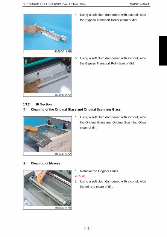
1. Remove the Paper Dust Remover Assy.2. Using a brush, whisk dust and dirt off the Paper
Dust Remover.
4035D009AA
1-12
☞ 1-272. Open the Right Door.
3. Remove two screws, unplug one connector, and remove the Manual Bypass Assy.
4532D008AC
Di1611/Di2011 FIELD SERVICE Ver.1.0 Mar. 2004 MAINTENANCE
5.3.2 IR Section(1) Cleaning of the Original Glass and Original Scanning Glass
4. Using a soft cloth dampened with alcohol, wipe the Bypass Transport Roller clean of dirt.
4035D011AB
5. Using a soft cloth dampened with alcohol, wipe the Bypass Transport Roll clean of dirt.
4532D015AA
1. Using a soft cloth dampened with alcohol, wipe the Original Glass and Original Scanning Glass clean of dirt.
1-13
(2) Cleaning of Mirrors
4035D013AA
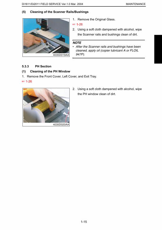
1. Remove the Original Glass.☞ 1-262. Using a soft cloth dampened with alcohol, wipe
the mirrors clean of dirt.
4035D014AB
Di1611/Di2011 FIELD SERVICE Ver.1.0 Mar. 2004MAINTENANCE
(3) Cleaning of the Lens
(4) Cleaning of the CCD Sensor
1. Remove the Original Glass.☞ 1-262. Using a soft cloth dampened with alcohol, wipe
the Lens clean of dirt.
4035D015AA
1. Remove the Original Glass.☞ 1-262. Remove four screws and the CCD Unit Cover.
4035D016AA
3. Pulling the tabs on both sides of the Lens Cover, remove the Lens Cover.
1-14
4035D017AA
4. Using a soft cloth dampened with alcohol, wipe the CCD Sensor clean of dirt.
4035D018AA
Di1611/Di2011 FIELD SERVICE Ver.1.0 Mar. 2004 MAINTENANCE
(5) Cleaning of the Scanner Rails/Bushings
5.3.3 PH Section(1) Cleaning of the PH Window1. Remove the Front Cover, Left Cover, and Exit Tray.☞ 1-26
1. Remove the Original Glass.☞ 1-262. Using a soft cloth dampened with alcohol, wipe
the Scanner rails and bushings clean of dirt.
NOTE• After the Scanner rails and bushings have been
cleaned, apply oil (copier lubricant A or FLOIL 947P).4035D019AA
2. Using a soft cloth dampened with alcohol, wipe the PH window clean of dirt.
4035D020AA
1-15
Di1611/Di2011 FIELD SERVICE Ver.1.0 Mar. 2004MAINTENANCE
5.3.4 Imaging Unit (IU)
NOTE• When the developer is to be changed, it is necessary that toner in the Recycled Toner
Recycling Duct and Toner Conveying Duct be fed into the Developer Mixing Chamber. To do that, remove the Toner Bottle and run “ATDC Auto Adjust” twice.
☞ 2-46
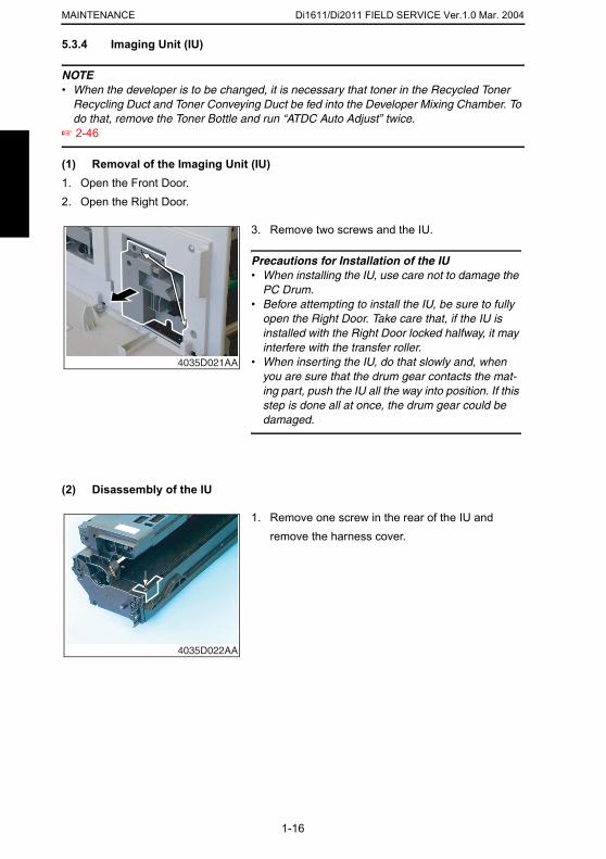
(1) Removal of the Imaging Unit (IU)1. Open the Front Door.2. Open the Right Door.
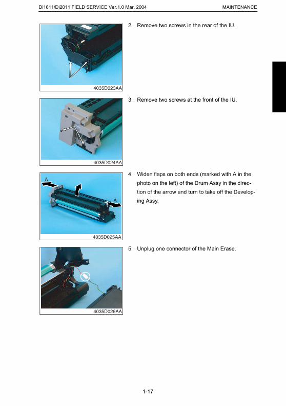
(2) Disassembly of the IU
3. Remove two screws and the IU.
Precautions for Installation of the IU• When installing the IU, use care not to damage the
PC Drum.• Before attempting to install the IU, be sure to fully
open the Right Door. Take care that, if the IU is installed with the Right Door locked halfway, it may interfere with the transfer roller.
• When inserting the IU, do that slowly and, when you are sure that the drum gear contacts the mat-ing part, push the IU all the way into position. If this step is done all at once, the drum gear could be damaged.
4035D021AA
1. Remove one screw in the rear of the IU and remove the harness cover.
1-16
4035D022AA
Di1611/Di2011 FIELD SERVICE Ver.1.0 Mar. 2004 MAINTENANCE
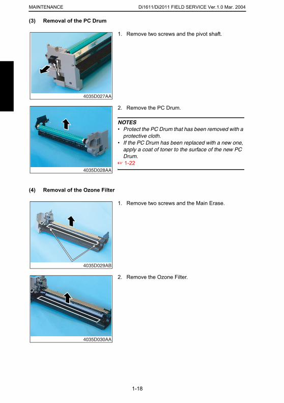
2. Remove two screws in the rear of the IU.
4035D023AA
3. Remove two screws at the front of the IU.
4035D024AA
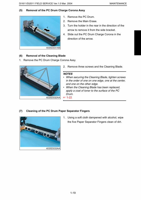
4. Widen flaps on both ends (marked with A in the photo on the left) of the Drum Assy in the direc-tion of the arrow and turn to take off the Develop-ing Assy.
4035D025AA
A
A
5. Unplug one connector of the Main Erase.
1-17
4035D026AA
Di1611/Di2011 FIELD SERVICE Ver.1.0 Mar. 2004MAINTENANCE
(3) Removal of the PC Drum
(4) Removal of the Ozone Filter
1. Remove two screws and the pivot shaft.
4035D027AA
2. Remove the PC Drum.
NOTES• Protect the PC Drum that has been removed with a
protective cloth.• If the PC Drum has been replaced with a new one,
apply a coat of toner to the surface of the new PC Drum.
☞ 1-224035D028AA
1. Remove two screws and the Main Erase.
1-18
4035D029AB
2. Remove the Ozone Filter.
4035D030AA
Di1611/Di2011 FIELD SERVICE Ver.1.0 Mar. 2004 MAINTENANCE
(5) Removal of the PC Drum Charge Corona Assy
(6) Removal of the Cleaning Blade1. Remove the PC Drum Charge Corona Assy.
(7) Cleaning of the PC Drum Paper Separator Fingers
1. Remove the PC Drum.2. Remove the Main Erase.3. Turn the holder in the rear in the direction of the
arrow to remove it from the side bracket.4. Slide out the PC Drum Charge Corona in the
direction of the arrow.
4035D031AB
43
2. Remove three screws and the Cleaning Blade.
NOTES• When securing the Cleaning Blade, tighten screws
in the order of one on one edge, one at the center, and one on the other edge.
• When the Cleaning Blade has been replaced, apply a coat of toner to the surface of the PC Drum.
☞ 1-224035D032AA
1. Using a soft cloth dampened with alcohol, wipe the five Paper Separator Fingers clean of dirt.
1-19
4035D033AA
Di1611/Di2011 FIELD SERVICE Ver.1.0 Mar. 2004MAINTENANCE
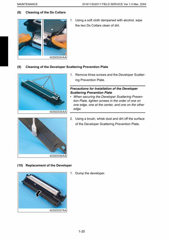
(8) Cleaning of the Ds Collars
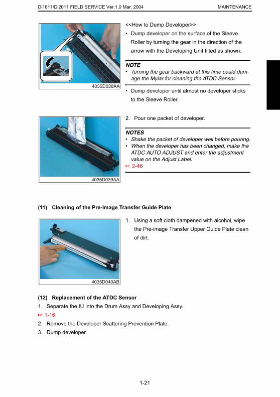
(9) Cleaning of the Developer Scattering Prevention Plate
1. Using a soft cloth dampened with alcohol, wipe the two Ds Collars clean of dirt.
4035D034AA
1. Remove three screws and the Developer Scatter-ing Prevention Plate.
Precautions for Installation of the Developer Scattering Prevention Plate• When securing the Developer Scattering Preven-
tion Plate, tighten screws in the order of one on one edge, one at the center, and one on the other edge.
4035D035AA
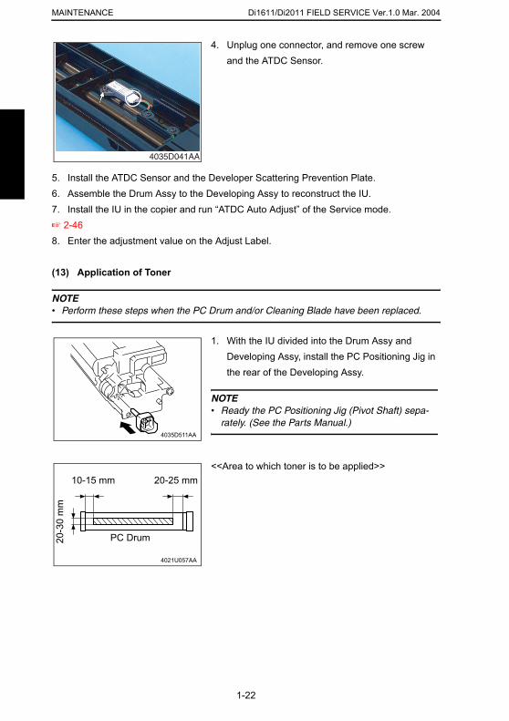
2. Using a brush, whisk dust and dirt off the surface of the Developer Scattering Prevention Plate.
1-20
(10) Replacement of the Developer
4035D036AA
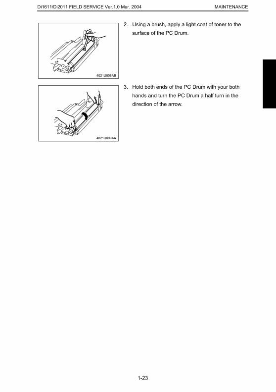
1. Dump the developer.
4035D037AA
Di1611/Di2011 FIELD SERVICE Ver.1.0 Mar. 2004 MAINTENANCE
(11) Cleaning of the Pre-Image Transfer Guide Plate
<<How to Dump Developer>>• Dump developer on the surface of the Sleeve
Roller by turning the gear in the direction of the arrow with the Developing Unit tilted as shown.
NOTE• Turning the gear backward at this time could dam-
age the Mylar for cleaning the ATDC Sensor.
• Dump developer until almost no developer sticks to the Sleeve Roller.
4035D038AA
2. Pour one packet of developer.
NOTES• Shake the packet of developer well before pouring.• When the developer has been changed, make the
ATDC AUTO ADJUST and enter the adjustment value on the Adjust Label.
☞ 2-46
4035D039AA
1. Using a soft cloth dampened with alcohol, wipe the Pre-image Transfer Upper Guide Plate clean of dirt.
1-21
(12) Replacement of the ATDC Sensor1. Separate the IU into the Drum Assy and Developing Assy.☞ 1-162. Remove the Developer Scattering Prevention Plate.3. Dump developer.
4035D040AB
Di1611/Di2011 FIELD SERVICE Ver.1.0 Mar. 2004MAINTENANCE
4. Unplug one connector, and remove one screw
5. Install the ATDC Sensor and the Developer Scattering Prevention Plate.6. Assemble the Drum Assy to the Developing Assy to reconstruct the IU.7. Install the IU in the copier and run “ATDC Auto Adjust” of the Service mode.☞ 2-46 8. Enter the adjustment value on the Adjust Label.
(13) Application of Toner
NOTE• Perform these steps when the PC Drum and/or Cleaning Blade have been replaced.
and the ATDC Sensor.
4035D041AA
1. With the IU divided into the Drum Assy and Developing Assy, install the PC Positioning Jig in the rear of the Developing Assy.
NOTE• Ready the PC Positioning Jig (Pivot Shaft) sepa-
rately. (See the Parts Manual.)4035D511AA
1-22
<<Area to which toner is to be applied>>
4021U057AA
20-25 mm10-15 mm
20-3
0 m
m
PC Drum
Di1611/Di2011 FIELD SERVICE Ver.1.0 Mar. 2004 MAINTENANCE
2. Using a brush, apply a light coat of toner to the surface of the PC Drum.
4021U008AB
3. Hold both ends of the PC Drum with your both hands and turn the PC Drum a half turn in the direction of the arrow.
4021U009AA
1-23
Di1611/Di2011 FIELD SERVICE Ver.1.0 Mar. 2004MAINTENANCE
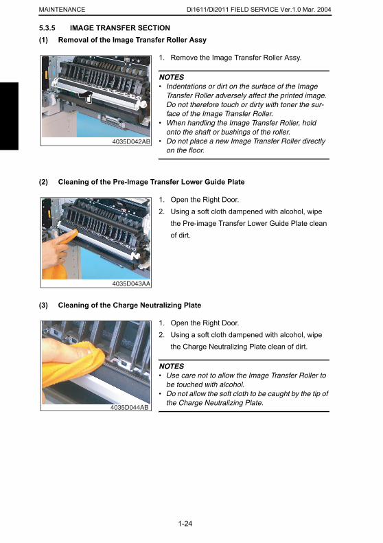
5.3.5 IMAGE TRANSFER SECTION(1) Removal of the Image Transfer Roller Assy
(2) Cleaning of the Pre-Image Transfer Lower Guide Plate
(3) Cleaning of the Charge Neutralizing Plate
1. Remove the Image Transfer Roller Assy.
NOTES• Indentations or dirt on the surface of the Image
Transfer Roller adversely affect the printed image. Do not therefore touch or dirty with toner the sur-face of the Image Transfer Roller.
• When handling the Image Transfer Roller, hold onto the shaft or bushings of the roller.
• Do not place a new Image Transfer Roller directly on the floor.
4035D042AB
1. Open the Right Door.2. Using a soft cloth dampened with alcohol, wipe
the Pre-image Transfer Lower Guide Plate clean of dirt.
4035D043AA
1. Open the Right Door.2. Using a soft cloth dampened with alcohol, wipe
the Charge Neutralizing Plate clean of dirt.
1-24
NOTES• Use care not to allow the Image Transfer Roller to
be touched with alcohol.• Do not allow the soft cloth to be caught by the tip of
the Charge Neutralizing Plate. 4035D044AB
Di1611/Di2011 FIELD SERVICE Ver.1.0 Mar. 2004 MAINTENANCE
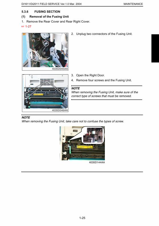
5.3.6 FUSING SECTION
(1) Removal of the Fusing Unit1. Remove the Rear Cover and Rear Right Cover.☞ 1-27NOTEWhen removing the Fusing Unit, take care not to confuse the types of screw.
2. Unplug two connectors of the Fusing Unit.
4035D045AA
3. Open the Right Door.4. Remove four screws and the Fusing Unit.
NOTEWhen removing the Fusing Unit, make sure of the correct type of screws that must be removed.
4035D046AA
1-25
4035D144AA
Di1611/Di2011 FIELD SERVICE Ver.1.0 Mar. 2004MAINTENANCE
6. MISCELLANEOUS PARTS
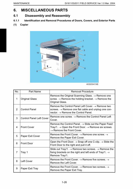
6.1 Disassembly and Reassembly6.1.1 Identification and Removal Procedures of Doors, Covers, and Exterior Parts(1) CopierNo. Part Name Removal Procedure
1 Original GlassRemove the Original Scanning Glass. → Remove one screw. → Remove the holding bracket. → Remove the Original Glass.
2 Control PanelRemove the Control Panel Left Cover. → Remove two screws. → Remove one flat cable and unplug one con-nector. → Remove the Control Panel.
3 Control Panel Left Cover Remove one screw. → Remove the Control Panel Left Cover.
4035D047AB
1
10
9
6
2
8
4
5
7
3
11
1-26
4 Front CoverRemove the Control Panel. → Slide out the Paper Feed Tray/1. → Open the Front Door. → Remove six screws. → Remove the Front Cover.
5 Paper Exit Cover Remove the Front Cover. → Remove one screw. → Remove the Paper Exit Cover.
6 Front Door Open the Front Door. → Snap off one C-clip. → Slide the Front Door to the right and pull it off.
7 Tray 1Slide out Tray/1. → Remove two screws. → Remove the fixing brackets on the right and left ends of Tray/1. → Remove Tray/1.
8 Left Cover Remove the Front Cover. → Remove five screws. → Remove the Left Cover.
9 Paper Exit Tray Remove the Front Cover. → Remove two screws. → Remove the Paper Exit Tray.

Di1611/Di2011 FIELD SERVICE Ver.1.0 Mar. 2004 MAINTENANCE
10 Rear Inside CoverRemove the Left Cover. → Remove the Paper Exit Tray. → Remove two screws. → Remove the Rear Inside Cover.
11 Original Scanning Glass Remove the Left Cover. → Remove two screws. → Remove the Original Scanning Glass.
No. Part Name Removal Procedure12 Rear Right Cover Remove two screws. → Remove the Rear Right Cover.
13 Left Rear Cover Remove the Upper Rear Cover. → Remove four screws. → Remove the Left Rear Cover.
No. Part Name Removal Procedure
4035D048AB
17
13
15
12
14
16
1-27
14 Upper Rear Cover Remove four screws. → Remove the Upper Rear Cover.
15 Rear Cover
Remove nine screws. → Remove the Rear Cover.
NOTEWhen the Rear Cover is to be installed, make sure of type of screw.(9735-0306-14 × 8 Screw, 9770-0308-14 × 1 Screw)
16 Right Rear Cover Remove the Upper Rear Cover. → Remove three screws. → Remove the Right Rear Cover.
17 Right CoverRemove the Upper Rear Cover. → Remove the Front Cover. → Remove four screws. → Remove the Right Cover.
Di1611/Di2011 FIELD SERVICE Ver.1.0 Mar. 2004MAINTENANCE
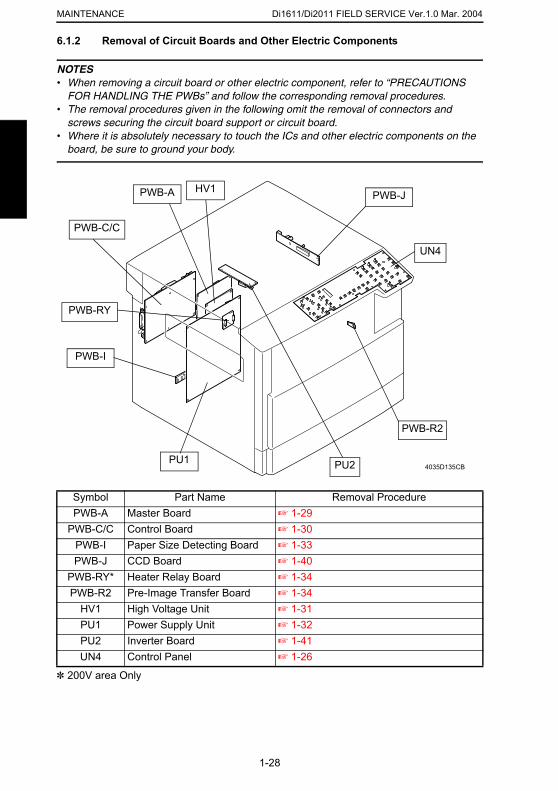
6.1.2 Removal of Circuit Boards and Other Electric Components
NOTES• When removing a circuit board or other electric component, refer to “PRECAUTIONS
FOR HANDLING THE PWBs” and follow the corresponding removal procedures.• The removal procedures given in the following omit the removal of connectors and
screws securing the circuit board support or circuit board.• Where it is absolutely necessary to touch the ICs and other electric components on the
board, be sure to ground your body.
Symbol Part Name Removal Procedure
PU1
HV1PWB-A
4035D135CB
PWB-C/C
PWB-J
PWB-I
PU2
UN4
PWB-R2
PWB-RY
1-28
✽ 200V area Only
PWB-A Master Board ☞ 1-29PWB-C/C Control Board ☞ 1-30
PWB-I Paper Size Detecting Board ☞ 1-33PWB-J CCD Board ☞ 1-40
PWB-RY* Heater Relay Board ☞ 1-34PWB-R2 Pre-Image Transfer Board ☞ 1-34
HV1 High Voltage Unit ☞ 1-31PU1 Power Supply Unit ☞ 1-32PU2 Inverter Board ☞ 1-41UN4 Control Panel ☞ 1-26
Di1611/Di2011 FIELD SERVICE Ver.1.0 Mar. 2004 MAINTENANCE
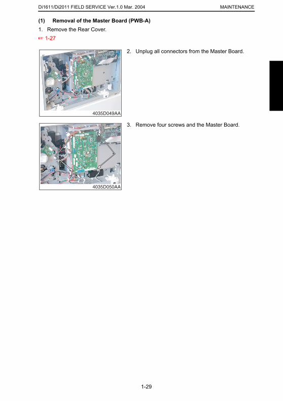
(1) Removal of the Master Board (PWB-A)
1. Remove the Rear Cover.☞ 1-272. Unplug all connectors from the Master Board.
4035D049AA
3. Remove four screws and the Master Board.
4035D050AA
1-29
Di1611/Di2011 FIELD SERVICE Ver.1.0 Mar. 2004MAINTENANCE
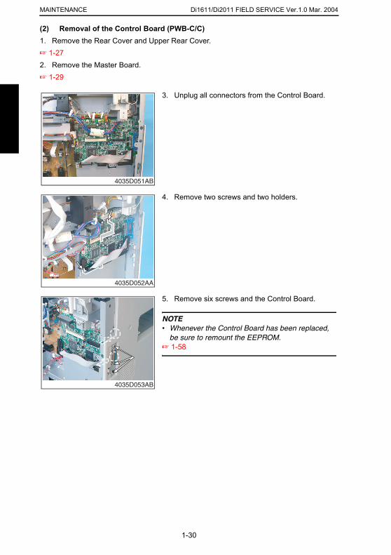
(2) Removal of the Control Board (PWB-C/C)1. Remove the Rear Cover and Upper Rear Cover.
☞ 1-272. Remove the Master Board.☞ 1-293. Unplug all connectors from the Control Board.
4035D051AB
4. Remove two screws and two holders.
4035D052AA
5. Remove six screws and the Control Board.
NOTE• Whenever the Control Board has been replaced,
be sure to remount the EEPROM.☞ 1-58
1-30
4035D053AB
Di1611/Di2011 FIELD SERVICE Ver.1.0 Mar. 2004 MAINTENANCE
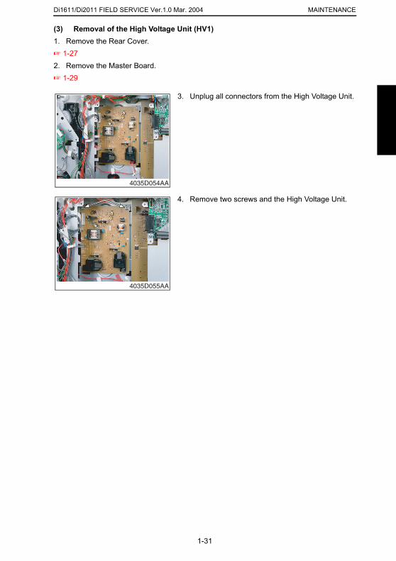
(3) Removal of the High Voltage Unit (HV1)
1. Remove the Rear Cover.☞ 1-272. Remove the Master Board.☞ 1-293. Unplug all connectors from the High Voltage Unit.
4035D054AA
4. Remove two screws and the High Voltage Unit.
4035D055AA
1-31
Di1611/Di2011 FIELD SERVICE Ver.1.0 Mar. 2004MAINTENANCE
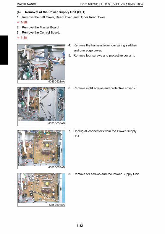
(4) Removal of the Power Supply Unit (PU1)1. Remove the Left Cover, Rear Cover, and Upper Rear Cover.
☞ 1-262. Remove the Master Board.3. Remove the Control Board.☞ 1-304. Remove the harness from four wiring saddles and one edge cover.
5. Remove four screws and protective cover 1.
4035D522AA
6. Remove eight screws and protective cover 2.
4035D056AB
7. Unplug all connectors from the Power Supply Unit.
1-32
4035D057AB
8. Remove six screws and the Power Supply Unit.
4035D523AA
Di1611/Di2011 FIELD SERVICE Ver.1.0 Mar. 2004 MAINTENANCE
(5) Removal of the Paper Size Detecting Board (PWB-I)
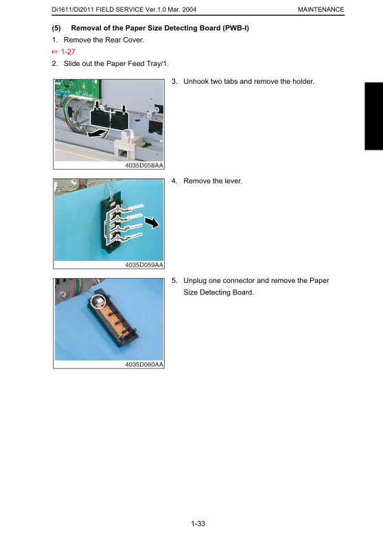
1. Remove the Rear Cover.☞ 1-272. Slide out the Paper Feed Tray/1.3. Unhook two tabs and remove the holder.
4035D058AA
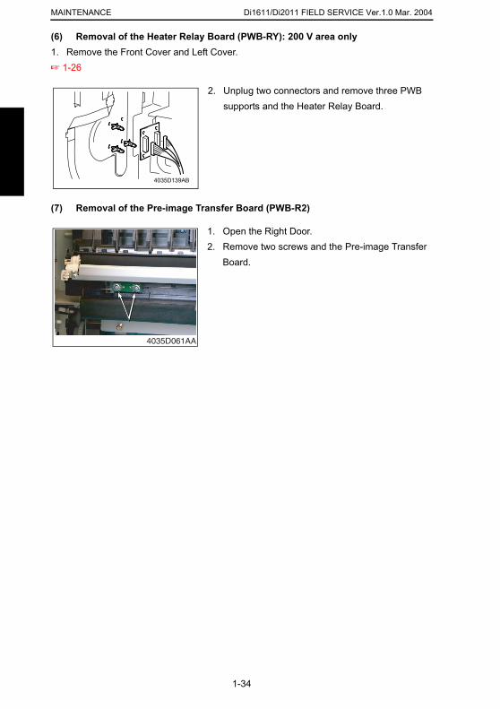
4. Remove the lever.
4035D059AA
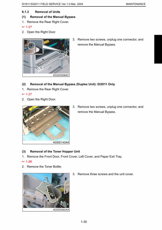
5. Unplug one connector and remove the Paper Size Detecting Board.
1-33
4035D060AA
Di1611/Di2011 FIELD SERVICE Ver.1.0 Mar. 2004MAINTENANCE
(6) Removal of the Heater Relay Board (PWB-RY): 200 V area only1. Remove the Front Cover and Left Cover.
☞ 1-26(7) Removal of the Pre-image Transfer Board (PWB-R2)
2. Unplug two connectors and remove three PWB supports and the Heater Relay Board.
4035D139AB
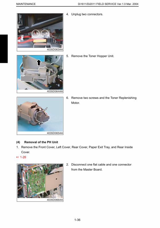
1. Open the Right Door.2. Remove two screws and the Pre-image Transfer
Board.
4035D061AA
1-34
Di1611/Di2011 FIELD SERVICE Ver.1.0 Mar. 2004 MAINTENANCE
6.1.3 Removal of Units
(1) Removal of the Manual Bypass1. Remove the Rear Right Cover.☞ 1-272. Open the Right Door.(2) Removal of the Manual Bypass (Duplex Unit): Di2011 Only1. Remove the Rear Right Cover.☞ 1-272. Open the Right Door.
3. Remove two screws, unplug one connector, and remove the Manual Bypass.
4532D008AC
3. Remove two screws, unplug one connector, and remove the Manual Bypass.
4035D143AA
1-35
(3) Removal of the Toner Hopper Unit1. Remove the Front Door, Front Cover, Left Cover, and Paper Exit Tray.☞ 1-262. Remove the Toner Bottle.
3. Remove three screws and the unit cover.
4035D062AA
Di1611/Di2011 FIELD SERVICE Ver.1.0 Mar. 2004MAINTENANCE
4. Unplug two connectors.
(4) Removal of the PH Unit
4035D063AA
5. Remove the Toner Hopper Unit.
4035D064AA
6. Remove two screws and the Toner Replenishing Motor.
4035D065AA
1-36
1. Remove the Front Cover, Left Cover, Rear Cover, Paper Exit Tray, and Rear Inside Cover.
☞ 1-26
2. Disconnect one flat cable and one connector from the Master Board.
4035D066AA
Di1611/Di2011 FIELD SERVICE Ver.1.0 Mar. 2004 MAINTENANCE
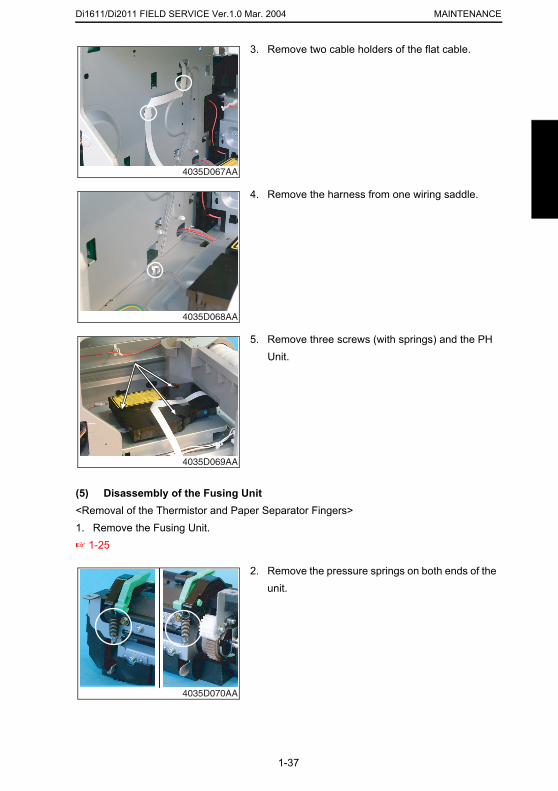
3. Remove two cable holders of the flat cable.
4035D067AA
4. Remove the harness from one wiring saddle.
4035D068AA
5. Remove three screws (with springs) and the PH Unit.
4035D069AA
1-37
(5) Disassembly of the Fusing Unit<Removal of the Thermistor and Paper Separator Fingers>1. Remove the Fusing Unit.☞ 1-25
2. Remove the pressure springs on both ends of the unit.
4035D070AA
Di1611/Di2011 FIELD SERVICE Ver.1.0 Mar. 2004MAINTENANCE
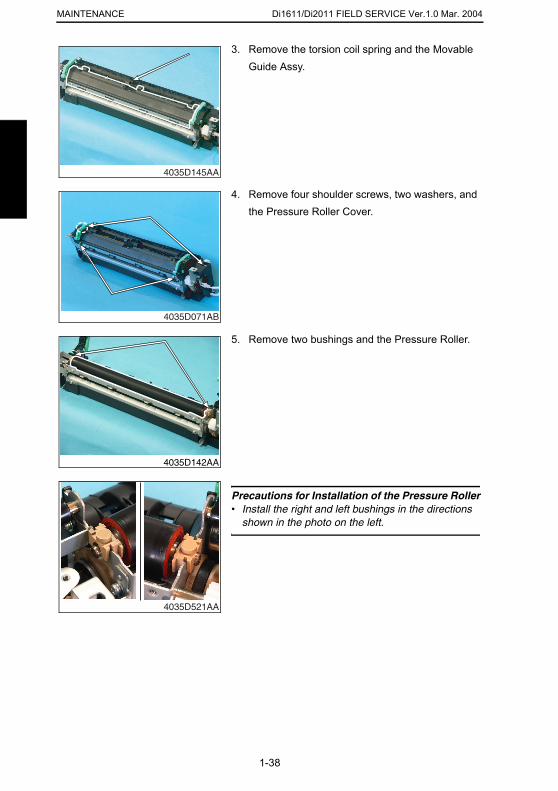
3. Remove the torsion coil spring and the Movable
Guide Assy.4035D145AA
4. Remove four shoulder screws, two washers, and the Pressure Roller Cover.
4035D071AB
5. Remove two bushings and the Pressure Roller.
4035D142AA
Precautions for Installation of the Pressure Roller• Install the right and left bushings in the directions
1-38
shown in the photo on the left.
4035D521AA
Di1611/Di2011 FIELD SERVICE Ver.1.0 Mar. 2004 MAINTENANCE
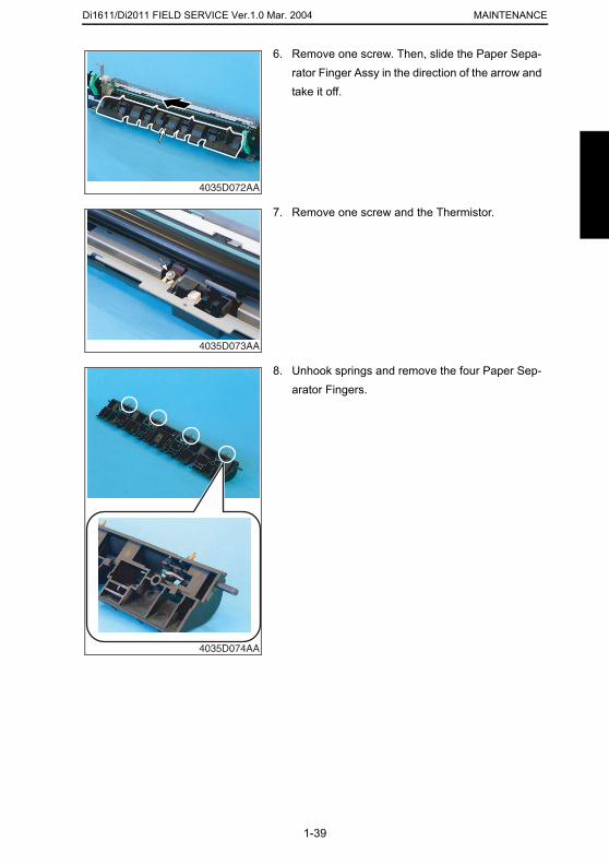
6. Remove one screw. Then, slide the Paper Sepa-rator Finger Assy in the direction of the arrow and take it off.
4035D072AA
7. Remove one screw and the Thermistor.
4035D073AA
8. Unhook springs and remove the four Paper Sep-arator Fingers.
1-39
4035D074AA
Di1611/Di2011 FIELD SERVICE Ver.1.0 Mar. 2004MAINTENANCE
6.1.4 Disassembly of the IR Section(1) Removal of the CCD Unit
1. Remove the Original Glass.☞ 1-262. Remove four screws and the CCD Unit Cover.
4035D016AA
3. Mark a line along the profile of the CCD Unit mounting bracket as shown on the left.
4035D075AA
4. Unplug one connector.
1-40
4035D076AA
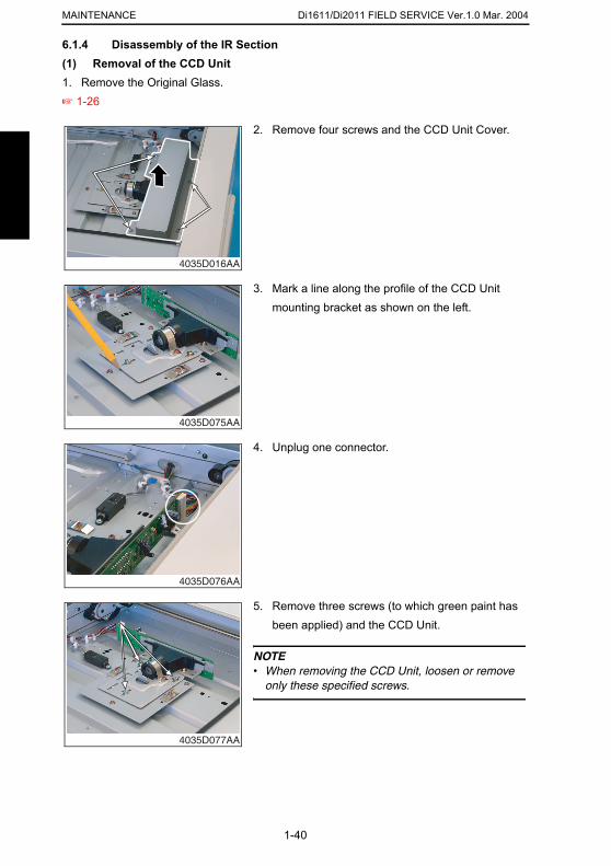
5. Remove three screws (to which green paint has been applied) and the CCD Unit.
NOTE• When removing the CCD Unit, loosen or remove
only these specified screws.
4035D077AA
Di1611/Di2011 FIELD SERVICE Ver.1.0 Mar. 2004 MAINTENANCE
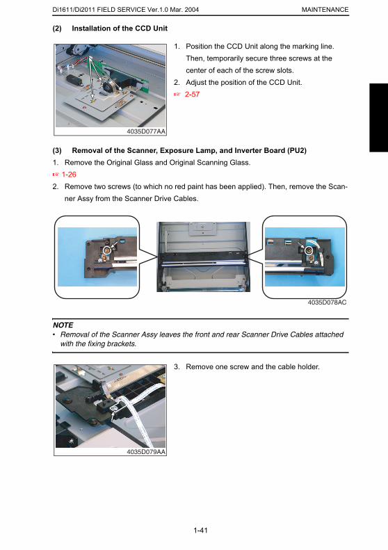
(2) Installation of the CCD Unit
(3) Removal of the Scanner, Exposure Lamp, and Inverter Board (PU2)1. Remove the Original Glass and Original Scanning Glass.☞ 1-262. Remove two screws (to which no red paint has been applied). Then, remove the Scan-
ner Assy from the Scanner Drive Cables.
NOTE• Removal of the Scanner Assy leaves the front and rear Scanner Drive Cables attached
1. Position the CCD Unit along the marking line. Then, temporarily secure three screws at the center of each of the screw slots.
2. Adjust the position of the CCD Unit.☞ 2-57
4035D077AA
4035D078AC
1-41
with the fixing brackets.
3. Remove one screw and the cable holder.
4035D079AA
Di1611/Di2011 FIELD SERVICE Ver.1.0 Mar. 2004MAINTENANCE
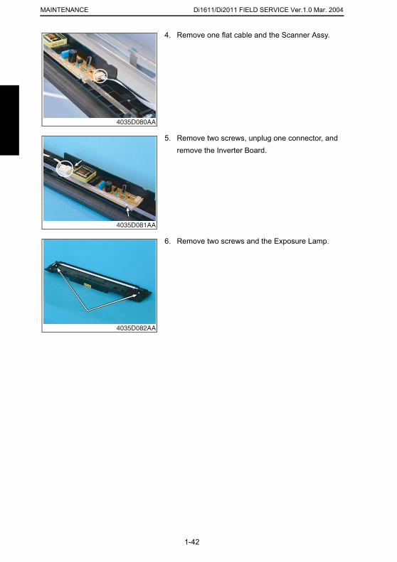
4. Remove one flat cable and the Scanner Assy.
4035D080AA
5. Remove two screws, unplug one connector, and remove the Inverter Board.
4035D081AA
6. Remove two screws and the Exposure Lamp.
4035D082AA
1-42
Di1611/Di2011 FIELD SERVICE Ver.1.0 Mar. 2004 MAINTENANCE
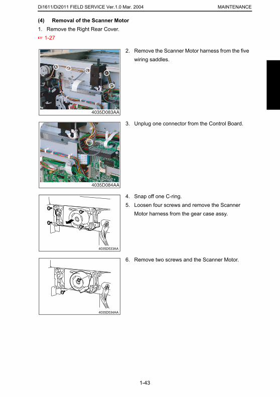
(4) Removal of the Scanner Motor
1. Remove the Right Rear Cover.☞ 1-272. Remove the Scanner Motor harness from the five wiring saddles.
4035D083AA
3. Unplug one connector from the Control Board.
4035D084AA
4. Snap off one C-ring.5. Loosen four screws and remove the Scanner
Motor harness from the gear case assy.
1-43
4035D533AA
6. Remove two screws and the Scanner Motor.
4035D534AA
Di1611/Di2011 FIELD SERVICE Ver.1.0 Mar. 2004MAINTENANCE
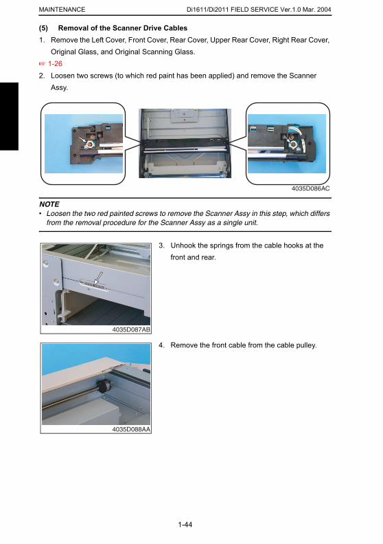
(5) Removal of the Scanner Drive Cables1. Remove the Left Cover, Front Cover, Rear Cover, Upper Rear Cover, Right Rear Cover,
Original Glass, and Original Scanning Glass.☞ 1-262. Loosen two screws (to which red paint has been applied) and remove the Scanner
Assy.
NOTE• Loosen the two red painted screws to remove the Scanner Assy in this step, which differs
from the removal procedure for the Scanner Assy as a single unit.
4035D086AC
3. Unhook the springs from the cable hooks at the front and rear.
4035D087AB
4. Remove the front cable from the cable pulley.
1-44
4035D088AA
Di1611/Di2011 FIELD SERVICE Ver.1.0 Mar. 2004 MAINTENANCE
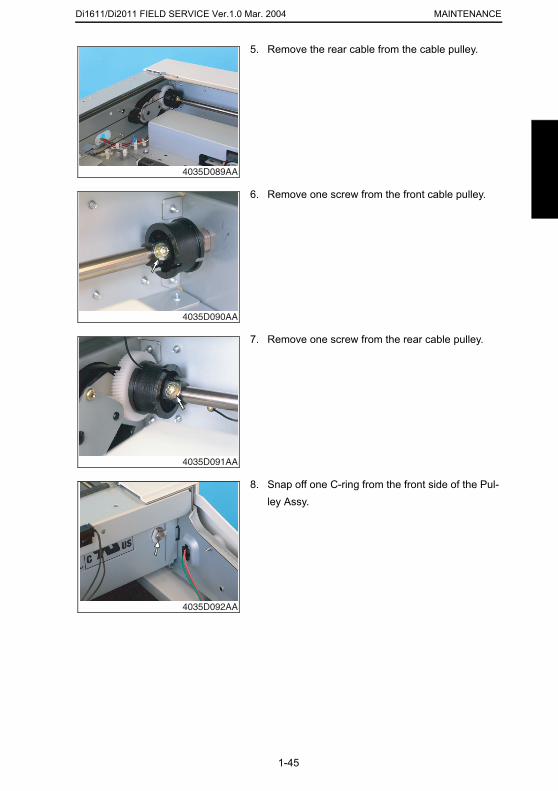
5. Remove the rear cable from the cable pulley.
4035D089AA
6. Remove one screw from the front cable pulley.
4035D090AA
7. Remove one screw from the rear cable pulley.
4035D091AA
8. Snap off one C-ring from the front side of the Pul-
1-45
ley Assy.
4035D092AA
Di1611/Di2011 FIELD SERVICE Ver.1.0 Mar. 2004MAINTENANCE
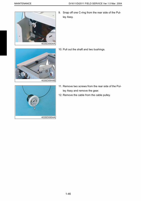
9. Snap off one C-ring from the rear side of the Pul-
ley Assy.4035D093AA
10. Pull out the shaft and two bushings.
4035D094AB
11. Remove two screws from the rear side of the Pul-ley Assy and remove the gear.
12. Remove the cable from the cable pulley.
4035D095AA
1-46
Di1611/Di2011 FIELD SERVICE Ver.1.0 Mar. 2004 MAINTENANCE
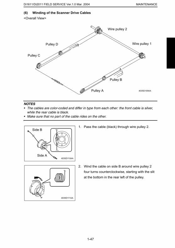
(6) Winding of the Scanner Drive Cables
<Overall View>NOTES• The cables are color-coded and differ in type from each other: the front cable is silver,
while the rear cable is black.• Make sure that no part of the cable rides on the other.
4035D109AAPulley A
Pulley B
Pulley C
Pulley D
Wire pulley 2
Wire pulley 1
1. Pass the cable (black) through wire pulley 2.Side B
1-47
4035D110AASide A
2. Wind the cable on side B around wire pulley 2 four turns counterclockwise, starting with the slit at the bottom in the rear left of the pulley.
4035D111AA
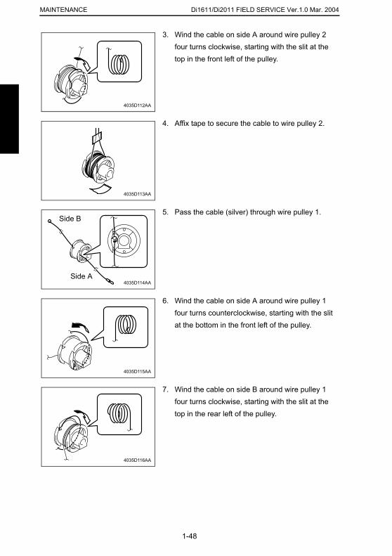
Di1611/Di2011 FIELD SERVICE Ver.1.0 Mar. 2004MAINTENANCE
3. Wind the cable on side A around wire pulley 2
four turns clockwise, starting with the slit at the top in the front left of the pulley.4035D112AA
4. Affix tape to secure the cable to wire pulley 2.
4035D113AA
5. Pass the cable (silver) through wire pulley 1.
4035D114AA
Side B
Side A
6. Wind the cable on side A around wire pulley 1 four turns counterclockwise, starting with the slit at the bottom in the front left of the pulley.
1-48
4035D115AA
7. Wind the cable on side B around wire pulley 1 four turns clockwise, starting with the slit at the top in the rear left of the pulley.
4035D116AA
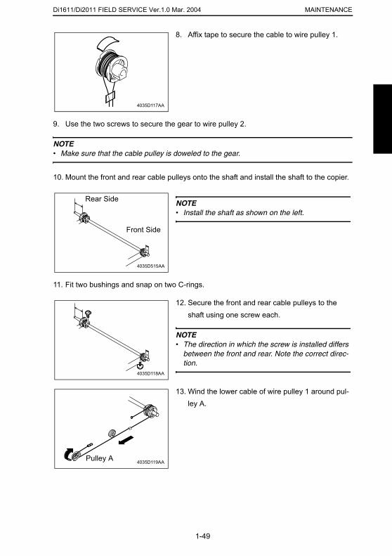
Di1611/Di2011 FIELD SERVICE Ver.1.0 Mar. 2004 MAINTENANCE
9. Use the two screws to secure the gear to wire pulley 2.
NOTE• Make sure that the cable pulley is doweled to the gear.
10. Mount the front and rear cable pulleys onto the shaft and install the shaft to the copier.
11. Fit two bushings and snap on two C-rings.
8. Affix tape to secure the cable to wire pulley 1.
4035D117AA
NOTE• Install the shaft as shown on the left.
4035D515AA
Rear Side
Front Side
12. Secure the front and rear cable pulleys to the shaft using one screw each.
NOTE• The direction in which the screw is installed differs
1-49
between the front and rear. Note the correct direc-tion.
4035D118AA
13. Wind the lower cable of wire pulley 1 around pul-ley A.
4035D119AAPulley A
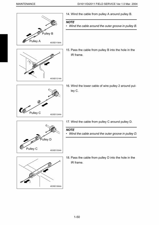
Di1611/Di2011 FIELD SERVICE Ver.1.0 Mar. 2004MAINTENANCE
14. Wind the cable from pulley A around pulley B.
NOTE• Wind the cable around the outer groove in pulley B.
4035D119AAPulley A
Pulley B
15. Pass the cable from pulley B into the hole in the IR frame.
4035D121AA
16. Wind the lower cable of wire pulley 2 around pul-ley C.
4035D124AAPulley C
17. Wind the cable from pulley C around pulley D.
NOTE• Wind the cable around the outer groove in pulley D.
Pulley D
1-50
4035D125AAPulley C
18. Pass the cable from pulley D into the hole in the IR frame.
4035D126AA
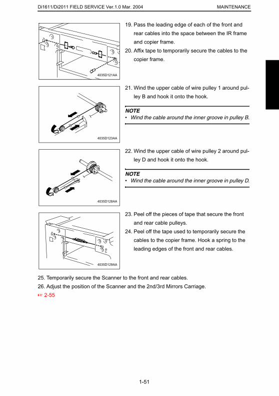
Di1611/Di2011 FIELD SERVICE Ver.1.0 Mar. 2004 MAINTENANCE
19. Pass the leading edge of each of the front and rear cables into the space between the IR frame and copier frame.
20. Affix tape to temporarily secure the cables to the copier frame.
4035D121AA
21. Wind the upper cable of wire pulley 1 around pul-ley B and hook it onto the hook.
NOTE• Wind the cable around the inner groove in pulley B.
4035D123AA
22. Wind the upper cable of wire pulley 2 around pul-ley D and hook it onto the hook.
NOTE• Wind the cable around the inner groove in pulley D.
4035D128AA
23. Peel off the pieces of tape that secure the front and rear cable pulleys.
24. Peel off the tape used to temporarily secure the cables to the copier frame. Hook a spring to the
1-51
25. Temporarily secure the Scanner to the front and rear cables.26. Adjust the position of the Scanner and the 2nd/3rd Mirrors Carriage.☞ 2-55
leading edges of the front and rear cables.
4035D129AA
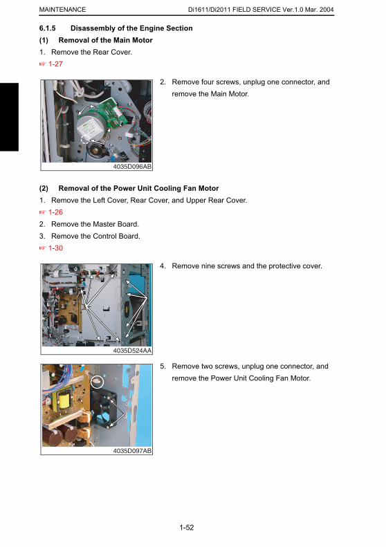
Di1611/Di2011 FIELD SERVICE Ver.1.0 Mar. 2004MAINTENANCE
6.1.5 Disassembly of the Engine Section(1) Removal of the Main Motor
1. Remove the Rear Cover.☞ 1-27(2) Removal of the Power Unit Cooling Fan Motor1. Remove the Left Cover, Rear Cover, and Upper Rear Cover.☞ 1-262. Remove the Master Board.3. Remove the Control Board.☞ 1-30
2. Remove four screws, unplug one connector, and remove the Main Motor.
4035D096AB
4. Remove nine screws and the protective cover.
4035D524AA
1-52
5. Remove two screws, unplug one connector, and remove the Power Unit Cooling Fan Motor.
4035D097AB
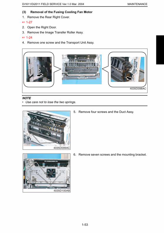
Di1611/Di2011 FIELD SERVICE Ver.1.0 Mar. 2004 MAINTENANCE
(3) Removal of the Fusing Cooling Fan Motor
1. Remove the Rear Right Cover.☞ 1-272. Open the Right Door.3. Remove the Image Transfer Roller Assy.☞ 1-244. Remove one screw and the Transport Unit Assy.NOTE• Use care not to lose the two springs.
4035D098AC
5. Remove four screws and the Duct Assy.
1-53
4035D099AC
6. Remove seven screws and the mounting bracket.
4035D100AB
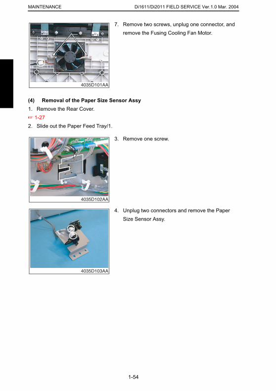
Di1611/Di2011 FIELD SERVICE Ver.1.0 Mar. 2004MAINTENANCE
7. Remove two screws, unplug one connector, and
(4) Removal of the Paper Size Sensor Assy1. Remove the Rear Cover.☞ 1-272. Slide out the Paper Feed Tray/1.
remove the Fusing Cooling Fan Motor.
4035D101AA
3. Remove one screw.
4035D102AA
4. Unplug two connectors and remove the Paper Size Sensor Assy.
1-54
4035D103AA
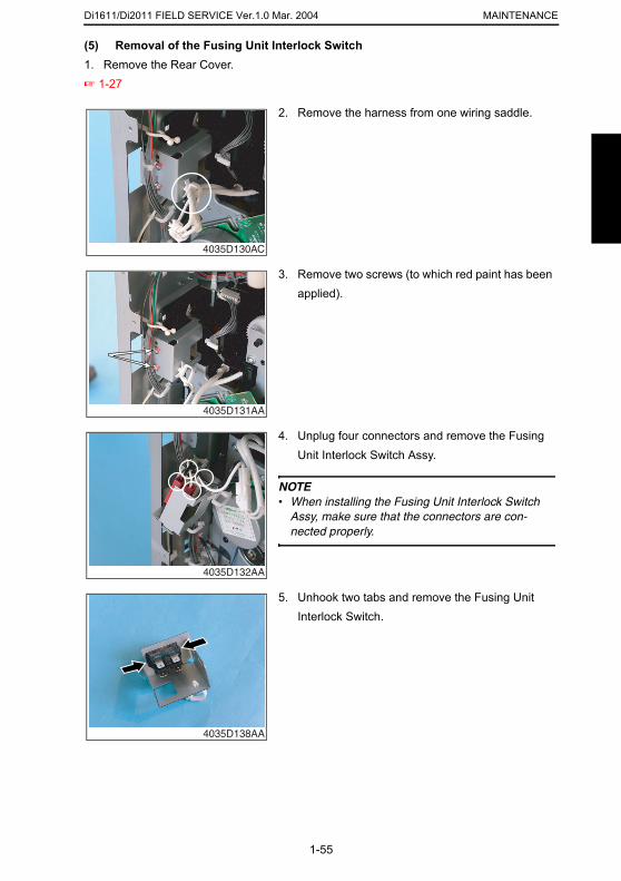
Di1611/Di2011 FIELD SERVICE Ver.1.0 Mar. 2004 MAINTENANCE
(5) Removal of the Fusing Unit Interlock Switch
1. Remove the Rear Cover.☞ 1-272. Remove the harness from one wiring saddle.
4035D130AC
3. Remove two screws (to which red paint has been applied).
4035D131AA
4. Unplug four connectors and remove the Fusing Unit Interlock Switch Assy.
NOTE• When installing the Fusing Unit Interlock Switch
Assy, make sure that the connectors are con-nected properly.
1-55
4035D132AA
5. Unhook two tabs and remove the Fusing Unit Interlock Switch.
4035D138AA
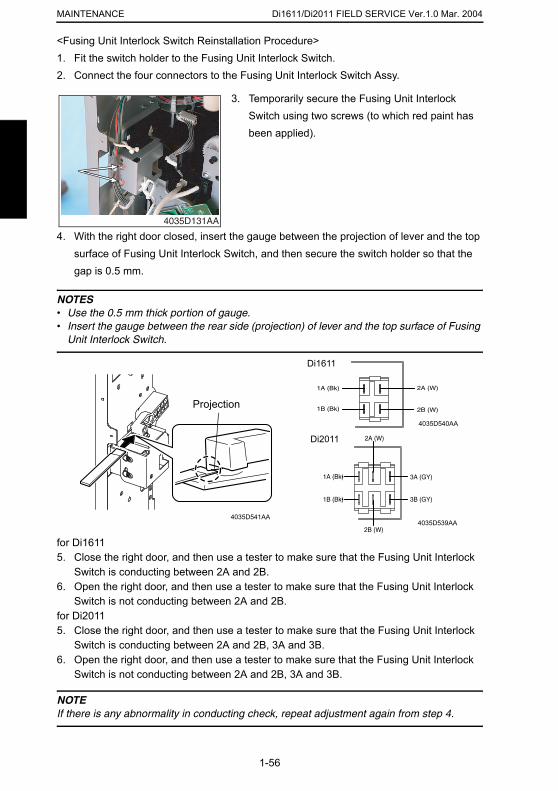
Di1611/Di2011 FIELD SERVICE Ver.1.0 Mar. 2004MAINTENANCE
<Fusing Unit Interlock Switch Reinstallation Procedure>1. Fit the switch holder to the Fusing Unit Interlock Switch.
2. Connect the four connectors to the Fusing Unit Interlock Switch Assy.4. With the right door closed, insert the gauge between the projection of lever and the top surface of Fusing Unit Interlock Switch, and then secure the switch holder so that the gap is 0.5 mm.
NOTES• Use the 0.5 mm thick portion of gauge.• Insert the gauge between the rear side (projection) of lever and the top surface of Fusing
Unit Interlock Switch.
3. Temporarily secure the Fusing Unit Interlock Switch using two screws (to which red paint has been applied).
4035D131AA
Projection
Di1611
Di2011
4035D540AA
1-56
for Di16115. Close the right door, and then use a tester to make sure that the Fusing Unit Interlock
Switch is conducting between 2A and 2B.6. Open the right door, and then use a tester to make sure that the Fusing Unit Interlock
Switch is not conducting between 2A and 2B.for Di20115. Close the right door, and then use a tester to make sure that the Fusing Unit Interlock
Switch is conducting between 2A and 2B, 3A and 3B.6. Open the right door, and then use a tester to make sure that the Fusing Unit Interlock
Switch is not conducting between 2A and 2B, 3A and 3B.
NOTEIf there is any abnormality in conducting check, repeat adjustment again from step 4.
4035D541AA4035D539AA
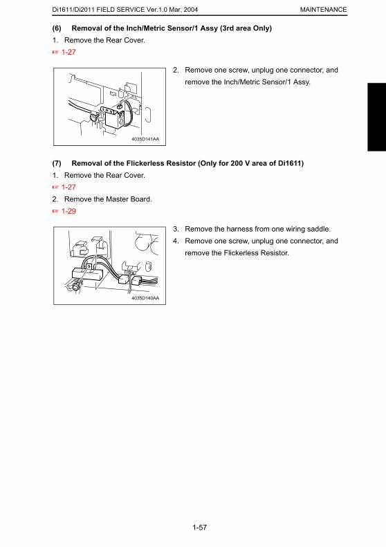
Di1611/Di2011 FIELD SERVICE Ver.1.0 Mar. 2004 MAINTENANCE
(6) Removal of the Inch/Metric Sensor/1 Assy (3rd area Only)
1. Remove the Rear Cover.☞ 1-27(7) Removal of the Flickerless Resistor (Only for 200 V area of Di1611)1. Remove the Rear Cover.☞ 1-272. Remove the Master Board.☞ 1-29
2. Remove one screw, unplug one connector, and remove the Inch/Metric Sensor/1 Assy.
4035D141AA
3. Remove the harness from one wiring saddle.4. Remove one screw, unplug one connector, and
remove the Flickerless Resistor.
4035D140AA
1-57
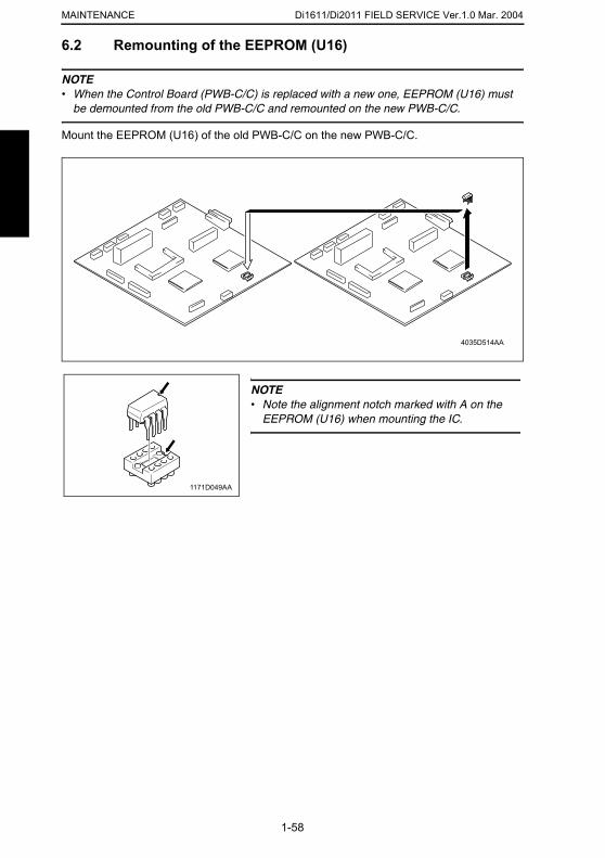
Di1611/Di2011 FIELD SERVICE Ver.1.0 Mar. 2004MAINTENANCE
6.2 Remounting of the EEPROM (U16)
NOTE• When the Control Board (PWB-C/C) is replaced with a new one, EEPROM (U16) must
be demounted from the old PWB-C/C and remounted on the new PWB-C/C.
Mount the EEPROM (U16) of the old PWB-C/C on the new PWB-C/C.
4035D514AA
NOTE• Note the alignment notch marked with A on the
EEPROM (U16) when mounting the IC.
1171D049AA
1-58
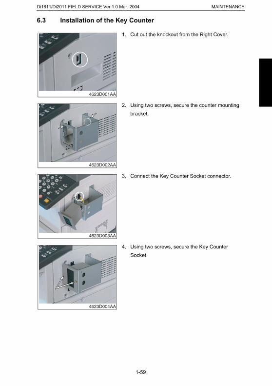
Di1611/Di2011 FIELD SERVICE Ver.1.0 Mar. 2004 MAINTENANCE
6.3 Installation of the Key Counter
1. Cut out the knockout from the Right Cover.
4623D001AA
2. Using two screws, secure the counter mounting bracket.
4623D002AA
3. Connect the Key Counter Socket connector.
4623D003AA
1-59
4. Using two screws, secure the Key Counter Socket.
4623D004AA
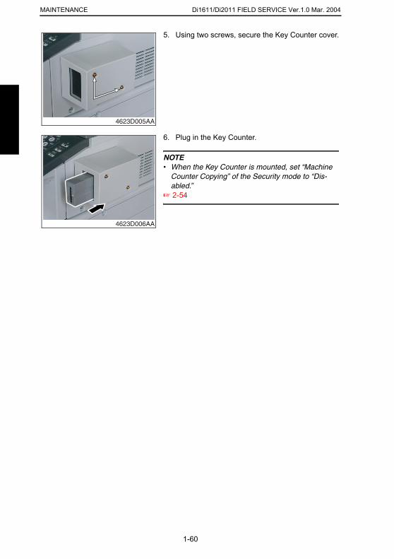
Di1611/Di2011 FIELD SERVICE Ver.1.0 Mar. 2004MAINTENANCE
5. Using two screws, secure the Key Counter cover.
4623D005AA
6. Plug in the Key Counter.
NOTE• When the Key Counter is mounted, set “Machine
Counter Copying” of the Security mode to “Dis-abled.”
☞ 2-54
4623D006AA
1-60

Di1611/Di2011 FIELD SERVICE Ver.1.0 Mar. 2004 MAINTENANCE
7. UPGRADING THE FIRMWARE7.1 Upgrading the Copier Firmware (PWB-C/C)7.1.1 Installing the Driver
NOTES• Since USB is used to upgrade the firmware, the host computer must be run on an OS of
Windows 98 or later.• The TWAIN driver must previously be installed in the host computer that is used to
upgrade the firmware.• If the TWAIN driver has not been installed, use the procedure below to install it.• If the TWAIN driver has already been installed, proceed with the section on “Firmware
upgrading procedure” to upgrade the firmware.
(1) Plug and Play Installation of the GDI Printer/TWAIN Driver<For Windows XP>1. Start the host computer.2. Turn on the power switch of copier.3. Use a USB cable to connect the copier to host computer.4. In the “Found New Hardware Wizard” dialog box, choose “Install from a list or specific
location (Advanced)”, and then click [Next].5. Under “Search for the best driver in these locations”, choose “Include this location in the
search”, and then click [Browse].6. Specify “\(name of any given language)\WinXP” in the folder in which the TWAIN driver
is stored, and then click [OK].7. Click [Next] and then [Finish].8. The “Found New Hardware Wizard” dialog box will appear again: Repeat steps 4~7 to
install all drivers.
<For Windows 2000>
1-61
1. Prepare the files necessary for upgrading the firmware, and copy them to PC.2. Start the host computer.3. Turn on the power switch of copier.4. Use a USB cable to connect the copier to host computer.
The “Found New Hardware Wizard” dialog box will appear.5. In the “Install Hardware Device Printers” dialog box, choose “Search for a suitable
driver for my device (recommended)”, and then click [Next].6. In the “Locate Driver Files” dialog box, choose “Specify a location”, and then click
[Next].7. Click [Browse], specify “\(name of any given language)\Win2000” in the folder in which
the TWAIN driver is stored, and then click [OK].8. Click [OK]. Then, continue following the instructions in the dialog boxes that will appear
until the “Completing the Found New Hardware Wizard” dialog box appears.
Di1611/Di2011 FIELD SERVICE Ver.1.0 Mar. 2004MAINTENANCE
9. Click [Finish].10. The “Found New Hardware Wizard” dialog box will appear again: Repeat steps 4~8 to
install all drivers.
<For Windows Me/98>1. Prepare the files necessary for upgrading the firmware, and copy them to PC.2. Start the host computer.3. Turn on the power switch of copier.4. Use a USB cable to connect the copier to host computer.
The “Add New Hardware Wizard” dialog box will appear.5. With Windows Me, choose “Specify the location of the driver (Advanced)”, and then
click [Next].With Windows 98, click [Next]. Then, in the dialog box that will then appear, choose “Search for the best driver for your device (recommended)”, and then click [Next].
6. Choose “Specify a location”, and then click [Browse].7. Specify “\(name of any given language)\Win9X” in the folder in which the TWAIN driver
is stored, and then click [OK].8. Click [Next]. Then, continue following the instructions in the dialog boxes that will
appear until the “Finish” button appears.9. Click [Finish].10. The “Add New Hardware Wizard” dialog box will appear again: Repeat steps 4~8 to
install all drivers.
1-62
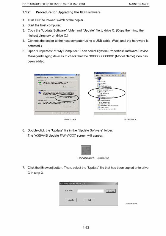
Di1611/Di2011 FIELD SERVICE Ver.1.0 Mar. 2004 MAINTENANCE
7.1.2 Procedure for Upgrading the GDI Firmware
1. Turn ON the Power Switch of the copier.2. Start the host computer.3. Copy the “Update Software” folder and “Update” file to drive C. (Copy them into the
highest directory on drive C.)4. Connect the copier to the host computer using a USB cable. (Wait until the hardware is
detected.)5. Open “Properties” of “My Computer.” Then select System Properties/Hardware/Device
Manager/Imaging devices to check that the “XXXXXXXXXXX” (Model Name) icon has been added.
6. Double-click the “Update” file in the “Update Software” folder.The “A3S/A4S Update F/W-VXXX” screen will appear.
4035D525CA 4035D526CA
1-63
7. Click the [Browse] button. Then, select the “Update” file that has been copied onto drive C in step 3.
4980D047AA
4035D531AA
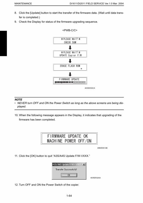
Di1611/Di2011 FIELD SERVICE Ver.1.0 Mar. 2004MAINTENANCE
8. Click the [Update] button to start the transfer of the firmware data. (Wait until data trans-
fer is completed.)9. Check the Display for status of the firmware upgrading sequence.
NOTE• NEVER turn OFF and ON the Power Switch as long as the above screens are being dis-
played.
10. When the following message appears in the Display, it indicates that upgrading of the firmware has been completed.
4035D530CA
<PWB-C/C>
1-64
11. Click the [OK] button to quit “A3S/A4S Update F/W-VXXX.”
12. Turn OFF and ON the Power Switch of the copier.
4980D051AB
4035D532AA
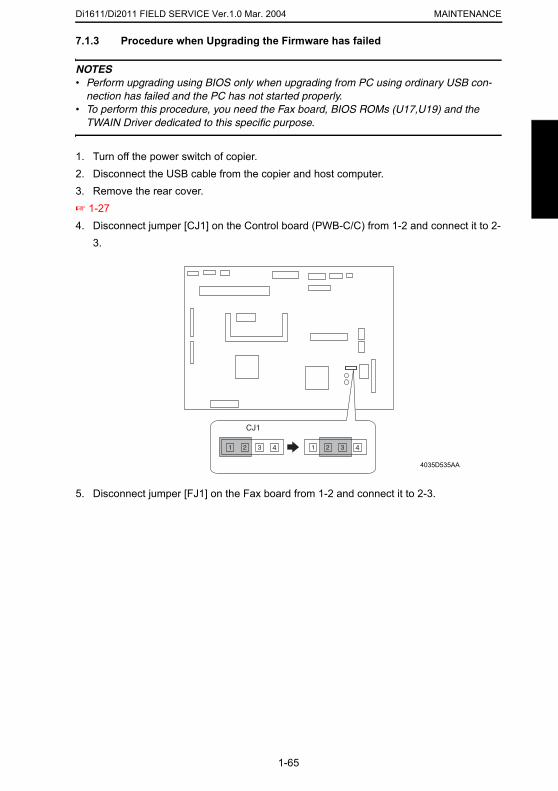
Di1611/Di2011 FIELD SERVICE Ver.1.0 Mar. 2004 MAINTENANCE
7.1.3 Procedure when Upgrading the Firmware has failed
NOTES• Perform upgrading using BIOS only when upgrading from PC using ordinary USB con-
nection has failed and the PC has not started properly.• To perform this procedure, you need the Fax board, BIOS ROMs (U17,U19) and the
TWAIN Driver dedicated to this specific purpose.
1. Turn off the power switch of copier.2. Disconnect the USB cable from the copier and host computer.3. Remove the rear cover.☞ 1-274. Disconnect jumper [CJ1] on the Control board (PWB-C/C) from 1-2 and connect it to 2-
3.
4035D535AA
1-65
5. Disconnect jumper [FJ1] on the Fax board from 1-2 and connect it to 2-3.
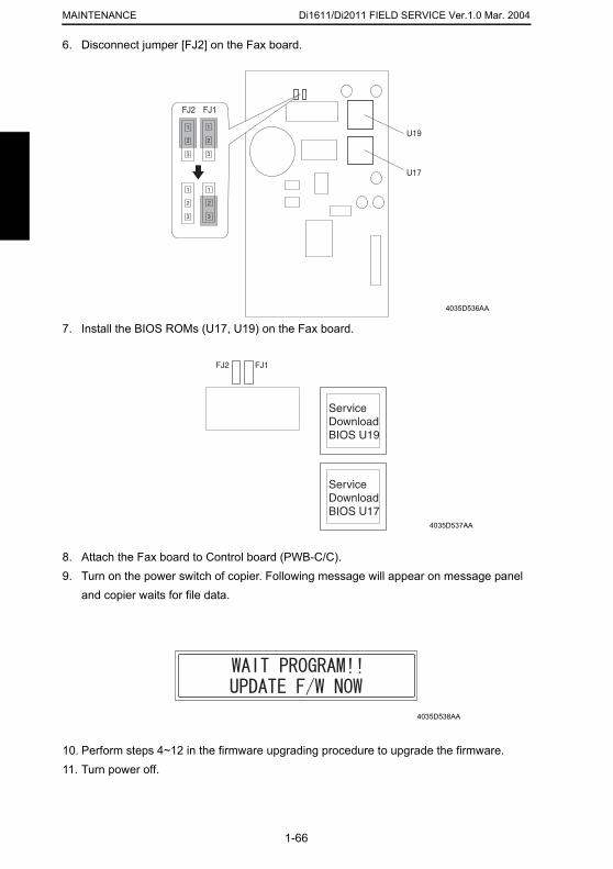
Di1611/Di2011 FIELD SERVICE Ver.1.0 Mar. 2004MAINTENANCE
6. Disconnect jumper [FJ2] on the Fax board.
7. Install the BIOS ROMs (U17, U19) on the Fax board.
8. Attach the Fax board to Control board (PWB-C/C).
4035D536AA
4035D537AA
1-66
9. Turn on the power switch of copier. Following message will appear on message panel and copier waits for file data.
10. Perform steps 4~12 in the firmware upgrading procedure to upgrade the firmware.11. Turn power off.
4035D538AA
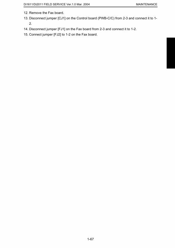
Di1611/Di2011 FIELD SERVICE Ver.1.0 Mar. 2004 MAINTENANCE
12. Remove the Fax board.
13. Disconnect jumper [CJ1] on the Control board (PWB-C/C) from 2-3 and connect it to 1-2.14. Disconnect jumper [FJ1] on the Fax board from 2-3 and connect it to 1-2.15. Connect jumper [FJ2] to 1-2 on the Fax board.
1-67

Di1611/Di2011 FIELD SERVICE Ver.1.0 Mar. 2004MAINTENANCE
1-68

ADJUSTING/SETTING
19971
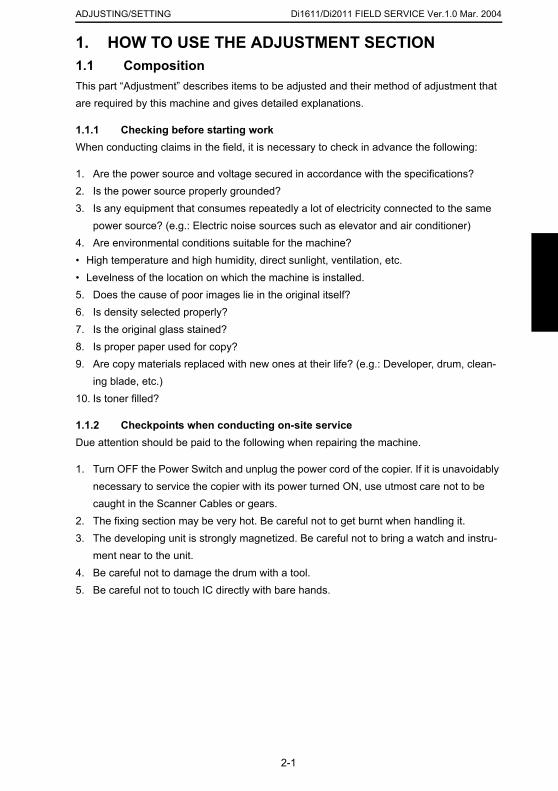
Di1611/Di2011 FIELD SERVICE Ver.1.0 Mar. 2004ADJUSTING/SETTING
1. HOW TO USE THE ADJUSTMENT SECTION1.1 CompositionThis part “Adjustment” describes items to be adjusted and their method of adjustment that are required by this machine and gives detailed explanations.
1.1.1 Checking before starting workWhen conducting claims in the field, it is necessary to check in advance the following:
1. Are the power source and voltage secured in accordance with the specifications?2. Is the power source properly grounded?3. Is any equipment that consumes repeatedly a lot of electricity connected to the same
power source? (e.g.: Electric noise sources such as elevator and air conditioner)4. Are environmental conditions suitable for the machine?• High temperature and high humidity, direct sunlight, ventilation, etc.• Levelness of the location on which the machine is installed.5. Does the cause of poor images lie in the original itself?6. Is density selected properly?7. Is the original glass stained?8. Is proper paper used for copy?9. Are copy materials replaced with new ones at their life? (e.g.: Developer, drum, clean-
ing blade, etc.)10. Is toner filled?
1.1.2 Checkpoints when conducting on-site serviceDue attention should be paid to the following when repairing the machine.
1. Turn OFF the Power Switch and unplug the power cord of the copier. If it is unavoidably necessary to service the copier with its power turned ON, use utmost care not to be
2-1
caught in the Scanner Cables or gears.2. The fixing section may be very hot. Be careful not to get burnt when handling it.3. The developing unit is strongly magnetized. Be careful not to bring a watch and instru-
ment near to the unit.4. Be careful not to damage the drum with a tool.5. Be careful not to touch IC directly with bare hands.

Di1611/Di2011 FIELD SERVICE Ver.1.0 Mar. 2004 ADJUSTING/SETTING
2-2

Di1611/Di2011 FIELD SERVICE Ver.1.0 Mar. 2004ADJUSTING/SETTING
2-3

Di1611/Di2011 FIELD SERVICE Ver.1.0 Mar. 2004 ADJUSTING/SETTING
2-4
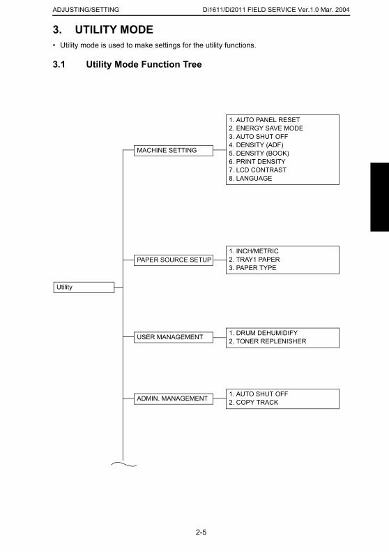
Di1611/Di2011 FIELD SERVICE Ver.1.0 Mar. 2004ADJUSTING/SETTING
3. UTILITY MODE• Utility mode is used to make settings for the utility functions.
3.1 Utility Mode Function Tree
Utility
1. AUTO PANEL RESET2. ENERGY SAVE MODE3. AUTO SHUT OFF4. DENSITY (ADF)5. DENSITY (BOOK)6. PRINT DENSITY7. LCD CONTRAST8. LANGUAGE
1. INCH/METRIC2. TRAY1 PAPER3. PAPER TYPE
PAPER SOURCE SETUP
1. DRUM DEHUMIDIFY2. TONER REPLENISHERUSER MANAGEMENT
MACHINE SETTING
2-5
ADMIN. MANAGEMENT1. AUTO SHUT OFF2. COPY TRACK
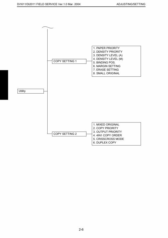
Di1611/Di2011 FIELD SERVICE Ver.1.0 Mar. 2004 ADJUSTING/SETTING
Utility
COPY SETTING 1
1. PAPER PRIORITY2. DENSITY PRIORITY3. DENSITY LEVEL (A)4. DENSITY LEVEL (M)5. BINDING POS.6. MARGIN SETTING7. ERASE SETTING8. SMALL ORIGINAL
COPY SETTING 2
1. MIXED ORIGINAL2. COPY PRIORITY3. OUTPUT PRIORITY4. 4IN1 COPY ORDER5. CRISSCROSS MODE6. DUPLEX COPY
2-6
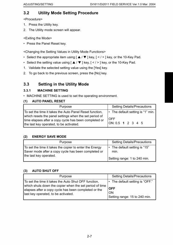
Di1611/Di2011 FIELD SERVICE Ver.1.0 Mar. 2004ADJUSTING/SETTING
3.2 Utility Mode Setting Procedure<Procedure>1. Press the Utility key.2. The Utility mode screen will appear.
<Exiting the Mode>• Press the Panel Reset key.
<Changing the Setting Values in Utility Mode Functions>• Select the appropriate item using [ ▲ / ▼ ] key, [ < / > ] key, or the 10-Key Pad.• Select the setting value using [ ▲ / ▼ ] key, [ < / > ] key, or the 10-Key Pad.1. Validate the selected setting value using the [Yes] key.2. To go back to the previous screen, press the [No] key.
3.3 Setting in the Utility Mode3.3.1 MACHINE SETTING• MACHINE SETTING is used to set the operating environment.(1) AUTO PANEL RESET
(2) ENERGY SAVE MODE
Purpose Setting Details/PrecautionsTo set the time it takes the Auto Panel Reset function, which resets the panel settings when the set period of time elapses after a copy cycle has been completed or the last key operated, to be activated.
• The default setting is “1” min.
OFFON: 0.5 1 2 3 4 5
Purpose Setting Details/PrecautionsTo set the time it takes the copier to enter the Energy Saver mode after a copy cycle has been completed or
• The default setting is “15” min.
2-7
(3) AUTO SHUT OFF
the last key operated.Setting range: 1 to 240 min.
Purpose Setting Details/PrecautionsTo set the time it takes the Auto Shut OFF function, which shuts down the copier when the set period of time elapses after a copy cycle has been completed or the last key operated, to be activated.
• The default setting is “OFF.”
OFFONSetting range: 15 to 240 min.
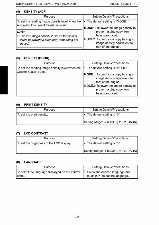
Di1611/Di2011 FIELD SERVICE Ver.1.0 Mar. 2004 ADJUSTING/SETTING
(4) DENSITY (ADF)Purpose Setting Details/Precautions
(5) DENSITY (BOOK)
(6) PRINT DENSITY
(7) LCD CONTRAST
To set the reading image density level when the Automatic Document Feeder is used.
NOTE• The low image density is set as the default
value to prevent a dirty copy from being pro-duced.
• The default setting is “MODE1.”
MODE1: To lower the image density to prevent a dirty copy from being produced.
MODE2: To produce a copy having an image density equivalent to that of the original.
Purpose Setting Details/PrecautionsTo set the reading image density level when the Original Glass is used.
• The default setting is “MODE1.”
MODE1: To produce a copy having an image density equivalent to that of the original.
MODE2: To lower the image density to prevent a dirty copy from being produced.
Purpose Setting Details/PrecautionsTo set the print density. • The default setting is “0.”
Setting range: -2 (LIGHT) to +2 (DARK)
Purpose Setting Details/PrecautionsTo set the brightness of the LCD display. • The default setting is “0.”
2-8
(8) LANGUAGE
Setting range: -1 (LIGHT) to +2 (DARK)
Purpose Setting Details/PrecautionsTo select the language displayed on the control panel.
• Select the desired language and touch [OK] to set the language.
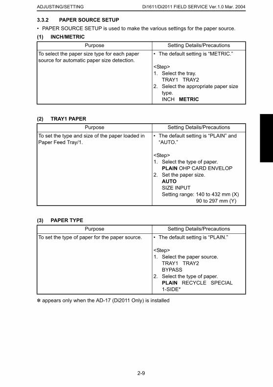
Di1611/Di2011 FIELD SERVICE Ver.1.0 Mar. 2004ADJUSTING/SETTING
3.3.2 PAPER SOURCE SETUP
• PAPER SOURCE SETUP is used to make the various settings for the paper source.(1) INCH/METRIC(2) TRAY1 PAPER
(3) PAPER TYPE
Purpose Setting Details/PrecautionsTo select the paper size type for each paper source for automatic paper size detection.
• The default setting is “METRIC.”
<Step>1. Select the tray.
TRAY1 TRAY22. Select the appropriate paper size
type.INCH METRIC
Purpose Setting Details/PrecautionsTo set the type and size of the paper loaded in Paper Feed Tray/1.
• The default setting is “PLAIN” and “AUTO.”
<Step>1. Select the type of paper.
PLAIN OHP CARD ENVELOP2. Set the paper size.
AUTOSIZE INPUTSetting range: 140 to 432 mm (X)
90 to 297 mm (Y)
Purpose Setting Details/PrecautionsTo set the type of paper for the paper source. • The default setting is “PLAIN.”
2-9
✽ appears only when the AD-17 (Di2011 Only) is installed
<Step>1. Select the paper source.
TRAY1 TRAY2BYPASS
2. Select the type of paper.PLAIN RECYCLE SPECIAL1-SIDE*

Di1611/Di2011 FIELD SERVICE Ver.1.0 Mar. 2004 ADJUSTING/SETTING
3.3.3 USER MANAGEMENT(1) DRUM DEHUMIDIFY
(2) TONER REPLENISHER
Purpose Setting Details/PrecautionsTo run a drum dry sequence.
✽ The drum dry sequence is run when an image problem occurs due to condensation formed on the surface of the PC Drum as a result of a sudden change in temperature or an increased humidity.
<Step>1. Select “DRUM DEHUMIDIFY” and
press the [Yes] key.2. The drum dry sequence is automat-
ically terminated after the lapse of a predetermined period of time and the initial screen reappears.
Purpose Setting Details/PrecautionsTo forcedly replenish the supply of toner when ID drops as a result of a reduced T/C ratio after a large number of copies have been made from an original having a high image density, thereby achieving the set T/C level.
• When “TONER REPLENISHER” is executed, the copier first detects the current toner density. If it is found that the density is lower than the ref-erence value, supply of toner is replenished and then toner is agi-tated. If the density is found to be higher than the reference value, the copier simply agitates toner to com-plete the sequence.
<Step>1. Select “TONER REPLENISHER”
and press the [Yes] key.2. The toner replenisher sequence is
automatically terminated after a given period of time or when the specified toner density is recov-ered. Then, the initial screen reap-pears.
2-10
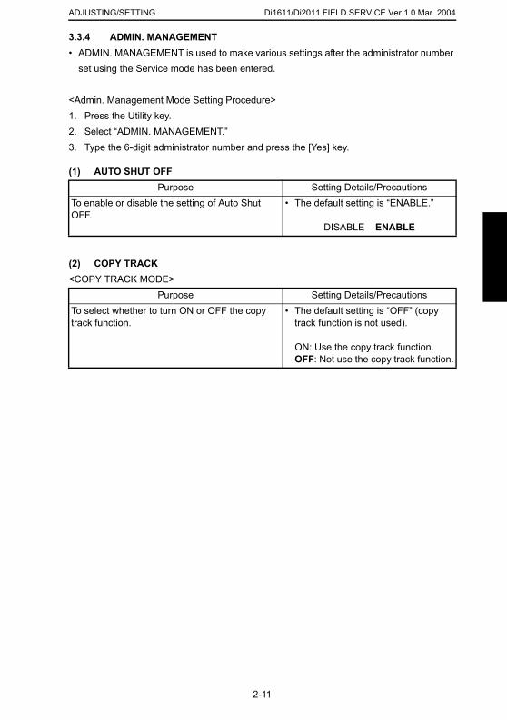
Di1611/Di2011 FIELD SERVICE Ver.1.0 Mar. 2004ADJUSTING/SETTING
3.3.4 ADMIN. MANAGEMENT
• ADMIN. MANAGEMENT is used to make various settings after the administrator numberset using the Service mode has been entered.
<Admin. Management Mode Setting Procedure>1. Press the Utility key.2. Select “ADMIN. MANAGEMENT.”3. Type the 6-digit administrator number and press the [Yes] key.
(1) AUTO SHUT OFF
(2) COPY TRACK<COPY TRACK MODE>
Purpose Setting Details/PrecautionsTo enable or disable the setting of Auto Shut OFF.
• The default setting is “ENABLE.”
DISABLE ENABLE
Purpose Setting Details/PrecautionsTo select whether to turn ON or OFF the copy track function.
• The default setting is “OFF” (copy track function is not used).
ON: Use the copy track function.OFF: Not use the copy track function.
2-11
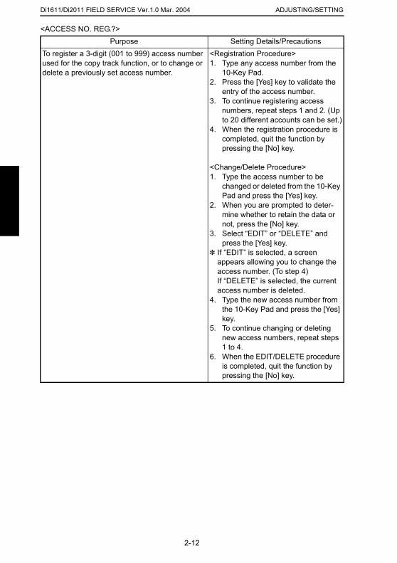
Di1611/Di2011 FIELD SERVICE Ver.1.0 Mar. 2004 ADJUSTING/SETTING
<ACCESS NO. REG.?>Purpose Setting Details/Precautions
To register a 3-digit (001 to 999) access number used for the copy track function, or to change or delete a previously set access number.
<Registration Procedure>1. Type any access number from the
10-Key Pad.2. Press the [Yes] key to validate the
entry of the access number.3. To continue registering access
numbers, repeat steps 1 and 2. (Up to 20 different accounts can be set.)
4. When the registration procedure is completed, quit the function by pressing the [No] key.
<Change/Delete Procedure>1. Type the access number to be
changed or deleted from the 10-Key Pad and press the [Yes] key.
2. When you are prompted to deter-mine whether to retain the data or not, press the [No] key.
3. Select “EDIT” or “DELETE” and press the [Yes] key.
✽ If “EDIT” is selected, a screen appears allowing you to change the access number. (To step 4)If “DELETE” is selected, the current access number is deleted.
4. Type the new access number from the 10-Key Pad and press the [Yes] key.
5. To continue changing or deleting new access numbers, repeat steps 1 to 4.
6. When the EDIT/DELETE procedure
2-12
is completed, quit the function by pressing the [No] key.
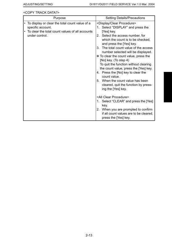
Di1611/Di2011 FIELD SERVICE Ver.1.0 Mar. 2004ADJUSTING/SETTING
<COPY TRACK DATA?>
Purpose Setting Details/Precautions• To display or clear the total count value of a specific account.
• To clear the total count values of all accounts under control.
<Display/Clear Procedure>1. Select “DISPLAY” and press the
[Yes] key.2. Select the access number, for
which the count is to be checked, and press the [Yes] key.
3. The total count value of the access number selected will be displayed.
✽ To clear the count value, press the [No] key. (To step 4)To quit the function without clearing the count value, press the [Yes] key.
4. Press the [No] key to clear the count value.
5. When the count value has been cleared, quit the function by press-ing the [Yes] key.
<All Clear Procedure>1. Select “CLEAR” and press the [Yes]
key.2. When you are prompted to confirm
if all count values are to be cleared, press the [Yes] key.
2-13
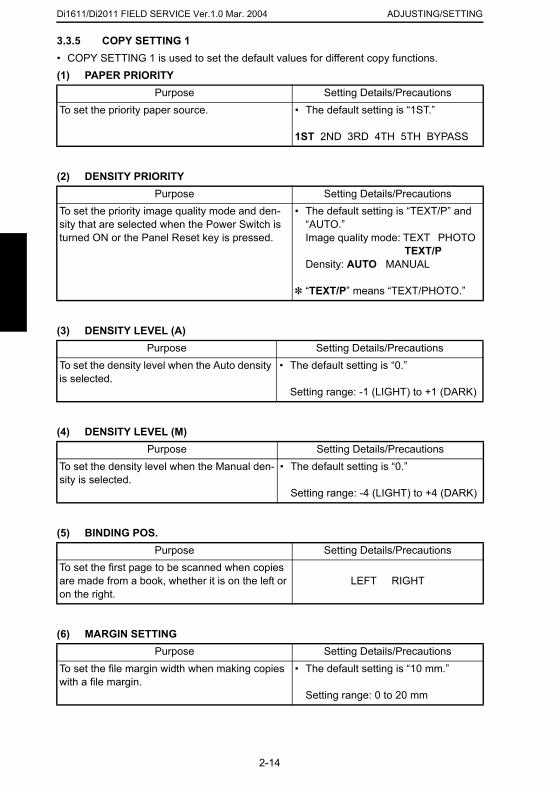
Di1611/Di2011 FIELD SERVICE Ver.1.0 Mar. 2004 ADJUSTING/SETTING
3.3.5 COPY SETTING 1• COPY SETTING 1 is used to set the default values for different copy functions.
(1) PAPER PRIORITY(2) DENSITY PRIORITY
(3) DENSITY LEVEL (A)
(4) DENSITY LEVEL (M)
Purpose Setting Details/PrecautionsTo set the priority paper source. • The default setting is “1ST.”
1ST 2ND 3RD 4TH 5TH BYPASS
Purpose Setting Details/PrecautionsTo set the priority image quality mode and den-sity that are selected when the Power Switch is turned ON or the Panel Reset key is pressed.
• The default setting is “TEXT/P” and “AUTO.”Image quality mode: TEXT PHOTO
TEXT/PDensity: AUTO MANUAL
✽ “TEXT/P” means “TEXT/PHOTO.”
Purpose Setting Details/PrecautionsTo set the density level when the Auto density is selected.
• The default setting is “0.”
Setting range: -1 (LIGHT) to +1 (DARK)
Purpose Setting Details/PrecautionsTo set the density level when the Manual den-sity is selected.
• The default setting is “0.”
Setting range: -4 (LIGHT) to +4 (DARK)
2-14
(5) BINDING POS.
(6) MARGIN SETTING
Purpose Setting Details/PrecautionsTo set the first page to be scanned when copies are made from a book, whether it is on the left or on the right.
LEFT RIGHT
Purpose Setting Details/PrecautionsTo set the file margin width when making copies with a file margin.
• The default setting is “10 mm.”
Setting range: 0 to 20 mm
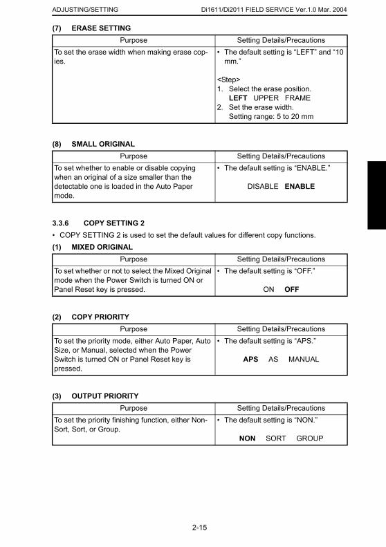
Di1611/Di2011 FIELD SERVICE Ver.1.0 Mar. 2004ADJUSTING/SETTING
(7) ERASE SETTING
(8) SMALL ORIGINAL
3.3.6 COPY SETTING 2• COPY SETTING 2 is used to set the default values for different copy functions.(1) MIXED ORIGINAL
(2) COPY PRIORITY
Purpose Setting Details/PrecautionsTo set the erase width when making erase cop-ies.
• The default setting is “LEFT” and “10 mm.”
<Step>1. Select the erase position.
LEFT UPPER FRAME2. Set the erase width.
Setting range: 5 to 20 mm
Purpose Setting Details/PrecautionsTo set whether to enable or disable copying when an original of a size smaller than the detectable one is loaded in the Auto Paper mode.
• The default setting is “ENABLE.”
DISABLE ENABLE
Purpose Setting Details/PrecautionsTo set whether or not to select the Mixed Original mode when the Power Switch is turned ON or Panel Reset key is pressed.
• The default setting is “OFF.”
ON OFF
Purpose Setting Details/Precautions
2-15
(3) OUTPUT PRIORITY
To set the priority mode, either Auto Paper, Auto Size, or Manual, selected when the Power Switch is turned ON or Panel Reset key is pressed.
• The default setting is “APS.”
APS AS MANUAL
Purpose Setting Details/PrecautionsTo set the priority finishing function, either Non-Sort, Sort, or Group.
• The default setting is “NON.”
NON SORT GROUP
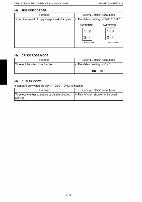
Di1611/Di2011 FIELD SERVICE Ver.1.0 Mar. 2004 ADJUSTING/SETTING
(4) 4IN1 COPY ORDERPurpose Setting Details/Precautions
(5) CRISSCROSS MODE
(6) DUPLEX COPY✽ appears only when the AD-17 (Di2011 Only) is installed
To set the layout of copy images in 4in1 copies. • The default setting is “PATTERN1.”
Purpose Setting Details/PrecautionsTo select the crisscross function. • The default setting is “ON.”
ON OFF
Purpose Setting Details/PrecautionsTo select whether to enable or disable 2-sided copying.
✽ This function should not be used.
4035S501AA
PATTERN1 PATTERN2
4035S502AA
2-16
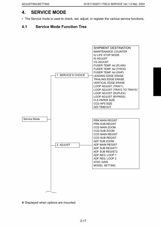
Di1611/Di2011 FIELD SERVICE Ver.1.0 Mar. 2004ADJUSTING/SETTING
4. SERVICE MODE• The Service mode is used to check, set, adjust, or register the various service functions.
4.1 Service Mode Function Tree
Service Mode
SHIPMENT DESTINATIONMAINTENANCE COUNTERIU LIFE STOP MODEID ADJUSTVG ADJUSTFUSER TEMP. Ad (PLAIN)FUSER TEMP. Ad (THICK)FUSER TEMP. Ad (OHP)LEADING EDGE ERASETRAILING EDGE ERASEVERTICAL EDGE ERASELOOP ADJUST (TRAY1)LOOP ADJUST (TRAY2 TO TRAY5)*LOOP ADJUST (DUPLEX)LOOP ADJUST (BYPASS)FLS PAPER SIZECCD APS SIZEGDI TIMEOUT
PRN MAIN REGISTPRN SUB REGISTCCD MAIN ZOOMCCD SUB ZOOMCCD MAIN REGISTCCD SUB REGISTADF SUB ZOOM
1. SERVICE’S CHOICE
2-17
✽ Displayed when options are mounted.
ADF MAIN REGISTADF SUB REGIST1ADF SUB REGIST2ADF REG. LOOP 1ADF REG. LOOP 2ATDC GAINMODEL SETTING
2. ADJUST
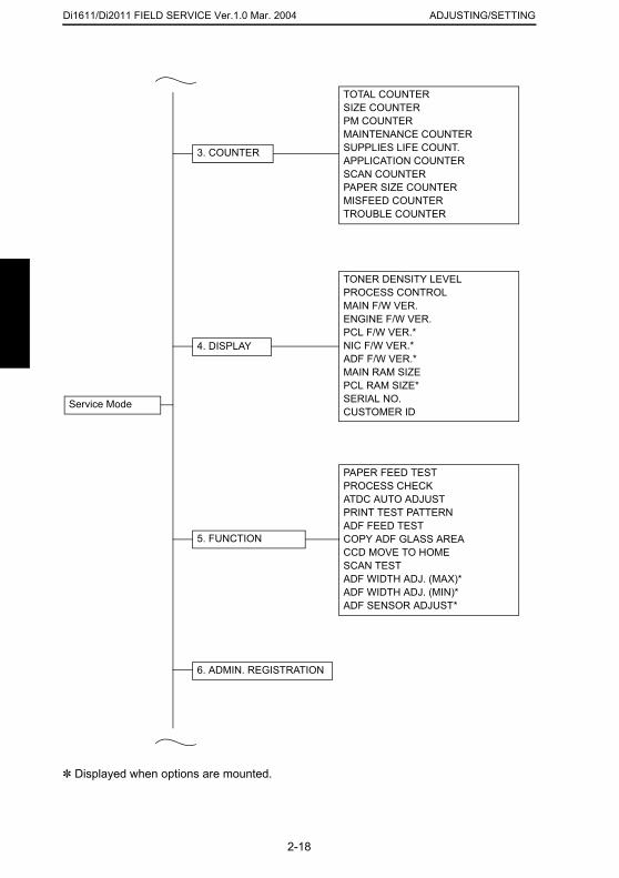
Di1611/Di2011 FIELD SERVICE Ver.1.0 Mar. 2004 ADJUSTING/SETTING
3. COUNTER
TOTAL COUNTERSIZE COUNTERPM COUNTERMAINTENANCE COUNTERSUPPLIES LIFE COUNT.APPLICATION COUNTERSCAN COUNTERPAPER SIZE COUNTERMISFEED COUNTERTROUBLE COUNTER
PAPER FEED TESTPROCESS CHECKATDC AUTO ADJUSTPRINT TEST PATTERNADF FEED TESTCOPY ADF GLASS AREACCD MOVE TO HOMESCAN TEST
TONER DENSITY LEVELPROCESS CONTROLMAIN F/W VER.ENGINE F/W VER.PCL F/W VER.*NIC F/W VER.*ADF F/W VER.*MAIN RAM SIZEPCL RAM SIZE*SERIAL NO.CUSTOMER ID
4. DISPLAY
Service Mode
5. FUNCTION
2-18
✽ Displayed when options are mounted.
ADF WIDTH ADJ. (MAX)*ADF WIDTH ADJ. (MIN)*ADF SENSOR ADJUST*
6. ADMIN. REGISTRATION
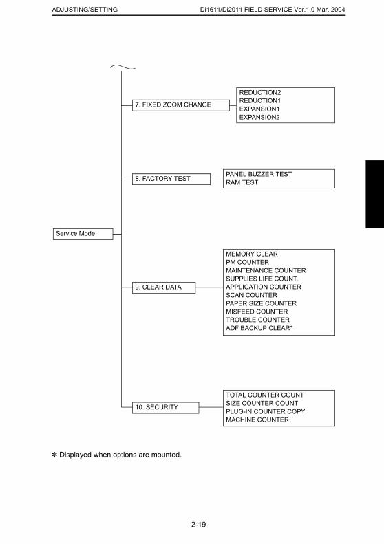
Di1611/Di2011 FIELD SERVICE Ver.1.0 Mar. 2004ADJUSTING/SETTING
REDUCTION2REDUCTION1EXPANSION1EXPANSION2
7. FIXED ZOOM CHANGE
8. FACTORY TESTPANEL BUZZER TESTRAM TEST
9. CLEAR DATA
MEMORY CLEARPM COUNTERMAINTENANCE COUNTERSUPPLIES LIFE COUNT.APPLICATION COUNTERSCAN COUNTERPAPER SIZE COUNTERMISFEED COUNTERTROUBLE COUNTERADF BACKUP CLEAR*
Service Mode
2-19
✽ Displayed when options are mounted.
TOTAL COUNTER COUNTSIZE COUNTER COUNTPLUG-IN COUNTER COPYMACHINE COUNTER
10. SECURITY
Di1611/Di2011 FIELD SERVICE Ver.1.0 Mar. 2004 ADJUSTING/SETTING
4.2 Service Mode Function Setting Procedure
NOTE• Care must be used to ensure that only the personnel who are involved in service jobs
know the procedure to enter the Service mode.
<Procedure>1. Press the Utility key.2. Press the following keys in this order.3. Stop → 0 → 0 → Stop → 0 → 14. The Service mode menu screen will appear.
<Exiting the Mode>• Press the Panel Reset key as many times as it is required to display the initial screen.
<Service Mode Function Setting Value Changing Procedure>1. Select the desired item using [ ▲ / ▼ ] key.2. Select the setting value using [ ▲ / ▼ ] key, [ < / > ] key, or the 10-Key Pad.3. Validate the selection by pressing the [Yes] key.4. To go back to previous screen, press the [No] key.
2-20
Di1611/Di2011 FIELD SERVICE Ver.1.0 Mar. 2004ADJUSTING/SETTING
4.3 Setting in the Service Mode4.3.1 SERVICE’S CHOICE• SERVICE’S CHOICE is used to make the various service settings.
(1) SHIPMENT DESTINATIONPurpose Setting Details/Precautions
To select the display of the fixed zoom ratios and paper sizes according to the applicable market-ing area.
• The default setting is “METRIC”
METRICINCHJAPANCHINAL. AMERICA (METRIC)L. AMERICA (INCH)
2-21
Di1611/Di2011 FIELD SERVICE Ver.1.0 Mar. 2004 ADJUSTING/SETTING
(2) MAINTENANCE COUNTERPurpose Setting Details/Precautions
(3) IU LIFE STOP MODE
To enter an appropriate counter value (0 to 999999) as the tentative maintenance time.
Specify the setting on maintenance counter to “1” or “2”: If the maintenance life is reached, the maintenance call (M1) or Tech. Rep. call [Call Service (M1)] will appear.
• The default setting is “0.”
0: Not counted1: Counted (The maintenance call dis-
play is given when the counter reaches 0.)
2: Counted (The Tech. Rep. call display is given and the initiation of any new copy cycle is inhibited when the counter reaches 0.)
✽ When “1” or “2” is selected, a screen will then appear to allow the counter value to be entered.
NOTE• The counter value is decremented
until it reaches -999999 even after it has counted 0.
Purpose Setting Details/PrecautionsWhen the Supplies Life Count. reaches the life value, the IU life will be detected. The mode when the IU life is reached, is specified by this setting.
• The default setting is “CONTINU-OUS.”
CONTINUOUS: Enables copying. Maintenance call display is given.STOP: Disables copying. Tech. Rep. call display is given and the initiation of any new copy cycle is inhibited.
NOTE
2-22
(4) ID ADJUST
• The counter value is decremented until it reaches -999999 even after it has counted 0. In this case, however, no image quality is guaranteed.
Purpose Setting Details/PrecautionsTo set the image density by varying Vg and Vb on the engine side.
✽ Used when the image density is high or low.
• The default setting is “0.”
Setting range: -3 to +3
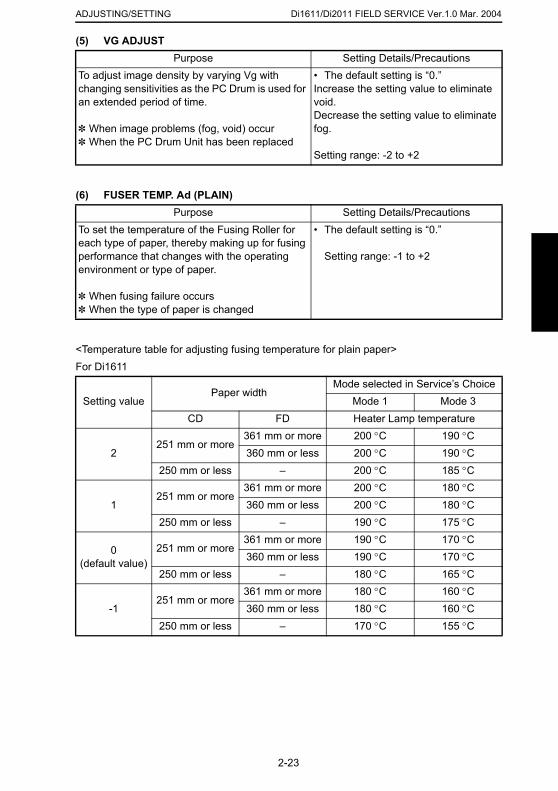
Di1611/Di2011 FIELD SERVICE Ver.1.0 Mar. 2004ADJUSTING/SETTING
(5) VG ADJUST
(6) FUSER TEMP. Ad (PLAIN)
<Temperature table for adjusting fusing temperature for plain paper> For Di1611
Purpose Setting Details/PrecautionsTo adjust image density by varying Vg with changing sensitivities as the PC Drum is used for an extended period of time.
✽ When image problems (fog, void) occur✽ When the PC Drum Unit has been replaced
• The default setting is “0.”Increase the setting value to eliminate void.Decrease the setting value to eliminate fog.
Setting range: -2 to +2
Purpose Setting Details/PrecautionsTo set the temperature of the Fusing Roller for each type of paper, thereby making up for fusing performance that changes with the operating environment or type of paper.
✽ When fusing failure occurs✽ When the type of paper is changed
• The default setting is “0.”
Setting range: -1 to +2
Setting valuePaper width
Mode selected in Service’s ChoiceMode 1 Mode 3
CD FD Heater Lamp temperature
2251 mm or more
361 mm or more 200 °C 190 °C360 mm or less 200 °C 190 °C
250 mm or less – 200 °C 185 °C361 mm or more 200 °C 180 °C
2-23
1251 mm or more
360 mm or less 200 °C 180 °C250 mm or less – 190 °C 175 °C
0(default value)
251 mm or more361 mm or more 190 °C 170 °C360 mm or less 190 °C 170 °C
250 mm or less – 180 °C 165 °C
-1251 mm or more
361 mm or more 180 °C 160 °C360 mm or less 180 °C 160 °C
250 mm or less – 170 °C 155 °C
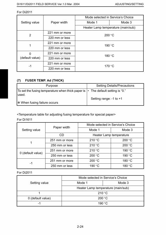
Di1611/Di2011 FIELD SERVICE Ver.1.0 Mar. 2004 ADJUSTING/SETTING
For Di2011Mode selected in Service’s Choice
(7) FUSER TEMP. Ad (THICK)
<Temperature table for adjusting fusing temperature for special paper>For Di1611
Setting value Paper width Mode 1 Mode 3Heater Lamp temperature (main/sub)
2221 mm or more
200 °C220 mm or less
1221 mm or more
190 °C220 mm or less
0(default value)
221 mm or more180 °C
220 mm or less
-1221 mm or more
170 °C220 mm or less
Purpose Setting Details/PrecautionsTo set the fusing temperature when thick paper is used.
✽ When fusing failure occurs
• The default setting is “0.”
Setting range: -1 to +1
Setting valuePaper width
Mode selected in Service’s ChoiceMode 1 Mode 3
CD Heater Lamp temperature
1251 mm or more 210 °C 200 °C250 mm or less 210 °C 200 °C251 mm or more 210 °C 190 °C
2-24
For Di2011
0 (default value)250 mm or less 200 °C 190 °C
-1251 mm or more 200 °C 180 °C250 mm or less 190 °C 180 °C
Setting valueMode selected in Service’s Choice
Mode 1 Mode 3Heater Lamp temperature (main/sub)
1 210 °C0 (default value) 200 °C
-1 190 °C
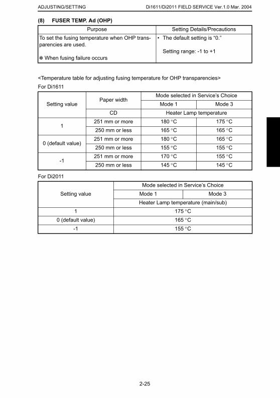
Di1611/Di2011 FIELD SERVICE Ver.1.0 Mar. 2004ADJUSTING/SETTING
(8) FUSER TEMP. Ad (OHP)
<Temperature table for adjusting fusing temperature for OHP transparencies>For Di1611
For Di2011
Purpose Setting Details/PrecautionsTo set the fusing temperature when OHP trans-parencies are used.
✽ When fusing failure occurs
• The default setting is “0.”
Setting range: -1 to +1
Setting valuePaper width
Mode selected in Service’s ChoiceMode 1 Mode 3
CD Heater Lamp temperature
1251 mm or more 180 °C 175 °C250 mm or less 165 °C 165 °C
0 (default value)251 mm or more 180 °C 165 °C250 mm or less 155 °C 155 °C
-1251 mm or more 170 °C 155 °C250 mm or less 145 °C 145 °C
Setting valueMode selected in Service’s Choice
Mode 1 Mode 3Heater Lamp temperature (main/sub)
1 175 °C0 (default value) 165 °C
-1 155 °C
2-25
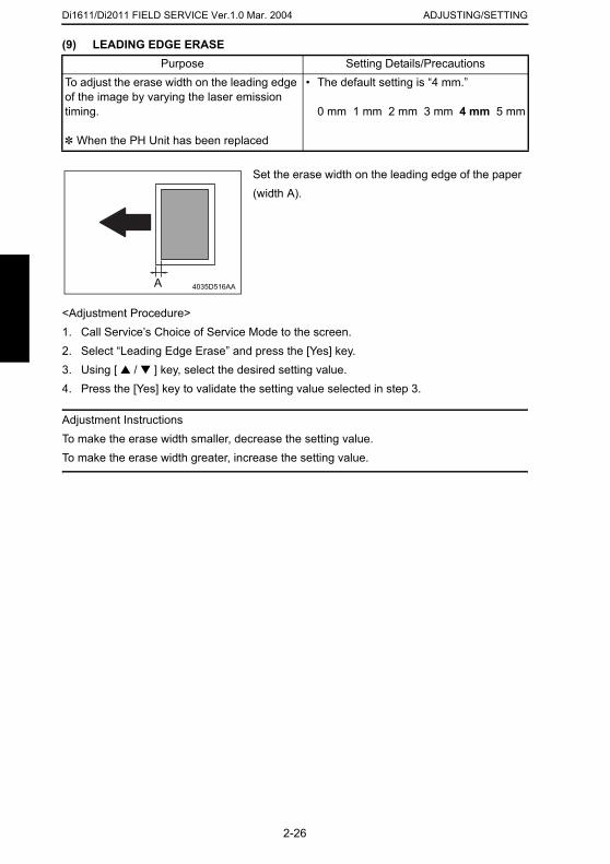
Di1611/Di2011 FIELD SERVICE Ver.1.0 Mar. 2004 ADJUSTING/SETTING
(9) LEADING EDGE ERASEPurpose Setting Details/Precautions
<Adjustment Procedure>1. Call Service’s Choice of Service Mode to the screen.2. Select “Leading Edge Erase” and press the [Yes] key.3. Using [ ▲ / ▼ ] key, select the desired setting value.4. Press the [Yes] key to validate the setting value selected in step 3.
Adjustment InstructionsTo make the erase width smaller, decrease the setting value.To make the erase width greater, increase the setting value.
To adjust the erase width on the leading edge of the image by varying the laser emission timing.
✽ When the PH Unit has been replaced
• The default setting is “4 mm.”
0 mm 1 mm 2 mm 3 mm 4 mm 5 mm
Set the erase width on the leading edge of the paper (width A).
4035D516AAA
2-26
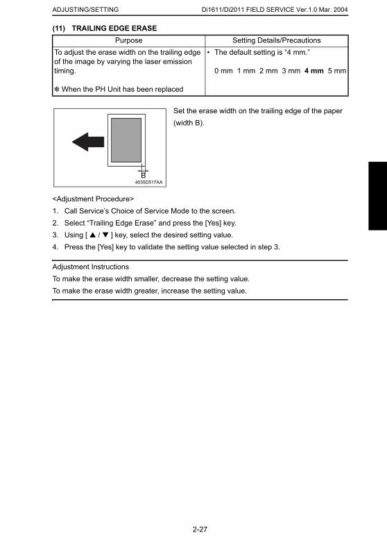
Di1611/Di2011 FIELD SERVICE Ver.1.0 Mar. 2004ADJUSTING/SETTING
(11) TRAILING EDGE ERASE
<Adjustment Procedure>1. Call Service’s Choice of Service Mode to the screen.2. Select “Trailing Edge Erase” and press the [Yes] key.3. Using [ ▲ / ▼ ] key, select the desired setting value.4. Press the [Yes] key to validate the setting value selected in step 3.
Adjustment InstructionsTo make the erase width smaller, decrease the setting value.To make the erase width greater, increase the setting value.
Purpose Setting Details/PrecautionsTo adjust the erase width on the trailing edge of the image by varying the laser emission timing.
✽ When the PH Unit has been replaced
• The default setting is “4 mm.”
0 mm 1 mm 2 mm 3 mm 4 mm 5 mm
Set the erase width on the trailing edge of the paper (width B).
B4035D517AA
2-27

Di1611/Di2011 FIELD SERVICE Ver.1.0 Mar. 2004 ADJUSTING/SETTING
(12) VERTICAL EDGE ERASEPurpose Setting Details/Precautions
<Adjustment Procedure>1. Call Service’s Choice of Service Mode to the screen.2. Select “Vertical Edge Erase” and press the [Yes] key.3. Using [ ▲ / ▼ ] key, select the desired setting value.4. Press the [Yes] key to validate the setting value selected in step 3.
Adjustment InstructionsTo make the erase width smaller, decrease the setting value.To make the erase width greater, increase the setting value.
To adjust the erase width on both edges of the image (in CD direction) by varying the laser emission timing.
✽ When the PH Unit has been replaced
Select the erase width value in the CD direction. (The default setting is “4 mm.”)
0 mm 1 mm 2 mm 3 mm 4 mm 5 mm
Set the erase width on both edges of the paper (width C).C
4035D518AA
C
2-28
Di1611/Di2011 FIELD SERVICE Ver.1.0 Mar. 2004ADJUSTING/SETTING
(13) LOOP ADJUST (TRAY1)
<Adjustment Procedure>1. Call Service’s Choice of Service Mode to the screen.2. Select “Loop Adjust (Tray1)” and press the [Yes] key.3. Using [ ▲ / ▼ ] key, select the desired setting value.4. Press the [Yes] key to validate the setting value selected in step 3.
Adjustment Instructions• Try a different setting value until there are no variations in the amount of void on the lead-
ing edge, and paper skew, fold, or misfeed.
(14) LOOP ADJUST (TRAY2 TO TRAY5)
Purpose Setting Details/PrecautionsTo adjust the length of the loop formed in the paper before the Synchronizing Roller.
✽ When a skew feed, fold, or misfeed of paper occurs
✽ When variations in the amount of void on the leading edge occurs
Setting range: -3.9 to 3.9 mm (1 step: 0.6 mm)
Purpose Setting Details/PrecautionsTo adjust the length of the loop formed in the paper before the Synchronizing Roller when the optional Paper Feed Unit is used.
✽ When a skew feed, fold, or misfeed of paper occurs
✽ When variations in the amount of void on
✽ Refer to the option service manual (PF-126) for details.
2-29
the leading edge occurs
Di1611/Di2011 FIELD SERVICE Ver.1.0 Mar. 2004 ADJUSTING/SETTING
(15) LOOP ADJUST (DUPLEX): Di2011 OnlyPurpose Setting Details/Precautions
(16) LOOP ADJUST (BYPASS)
<Adjustment Procedure>1. Call Service’s Choice of Service Mode to the screen.2. Select “Loop Adjust (Bypass)” and press the [Yes] key.3. Using [ ▲ / ▼ ] key, select the desired setting value.4. Press the [Yes] key to validate the setting value selected in step 3.
Adjustment Instructions• Try a different setting value until there are no variations in the amount of void on the lead-
ing edge, and paper skew, fold, or misfeed.
To adjust the length of the loop formed in the paper before the Synchronizing Roller.
✽ When a skew feed, fold, or misfeed of paper occurs
✽ When variations in the amount of void on the leading edge occurs
✽ Refer to the option service manual (AD-17) for details.
Purpose Setting Details/PrecautionsTo adjust the length of the loop formed in the paper before the Synchronizing Roller when the Manual Bypass is used.
✽ When a skew feed, fold, or misfeed of paper occurs
✽ When variations in the amount of void on the leading edge occurs
Setting range: -3.9 to 3.9 mm (1 step: 0.6 mm)
2-30
Di1611/Di2011 FIELD SERVICE Ver.1.0 Mar. 2004ADJUSTING/SETTING
(17) FLS PAPER SIZE
(18) CCD APS SIZE
(19) GDI TIMEOUT
Purpose Setting Details/PrecautionsTo select the paper size for FLS.
✽ When the FLS paper size is changed✽ At setup
• The default setting is “330✽210.”
330✽203 330✽210330✽216 330✽220337✽206
Purpose Setting Details/PrecautionsTo set the automatic paper size detection function for CCD scan.
• The default setting is “PATTERN1.”
PATTERN1 PATTERN2
Purpose Setting Details/PrecautionsTo specify the time for timeout when data from PC is interrupted during GDI printing.
• The default setting is “6.”
0 (5 sec.), 1 (10 sec.), 2 (20 sec.), 3 (30 sec.), 4 (40 sec.), 5 (50 sec.), 6 (60 sec.)
2-31
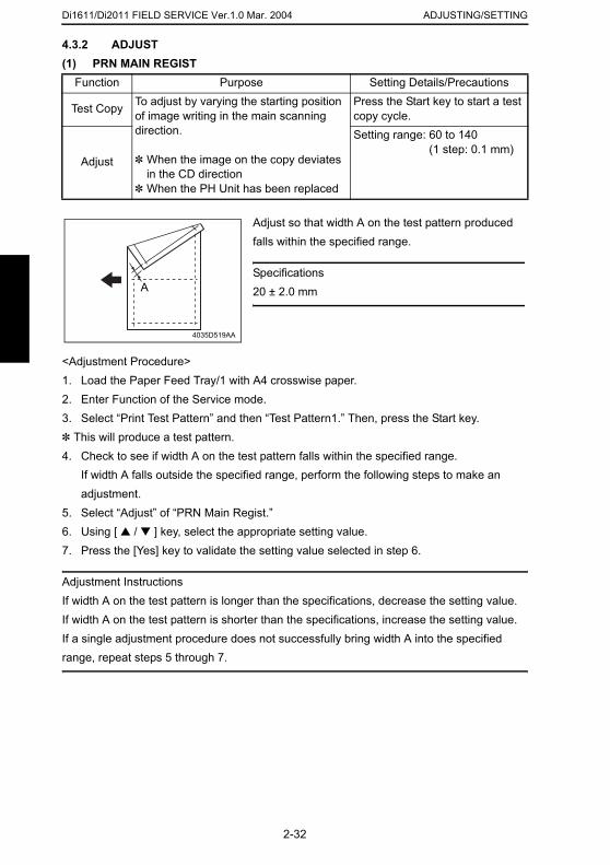
Di1611/Di2011 FIELD SERVICE Ver.1.0 Mar. 2004 ADJUSTING/SETTING
4.3.2 ADJUST(1) PRN MAIN REGIST
<Adjustment Procedure>1. Load the Paper Feed Tray/1 with A4 crosswise paper.2. Enter Function of the Service mode.3. Select “Print Test Pattern” and then “Test Pattern1.” Then, press the Start key.✽ This will produce a test pattern.4. Check to see if width A on the test pattern falls within the specified range.
If width A falls outside the specified range, perform the following steps to make an adjustment.
5. Select “Adjust” of “PRN Main Regist.”6. Using [ ▲ / ▼ ] key, select the appropriate setting value.7. Press the [Yes] key to validate the setting value selected in step 6.
Function Purpose Setting Details/Precautions
Test Copy To adjust by varying the starting position of image writing in the main scanning direction.
✽ When the image on the copy deviates in the CD direction
✽ When the PH Unit has been replaced
Press the Start key to start a test copy cycle.
Adjust
Setting range: 60 to 140 (1 step: 0.1 mm)
Adjust so that width A on the test pattern produced falls within the specified range.
Specifications20 ± 2.0 mm
4035D519AA
A
2-32
Adjustment InstructionsIf width A on the test pattern is longer than the specifications, decrease the setting value.If width A on the test pattern is shorter than the specifications, increase the setting value.If a single adjustment procedure does not successfully bring width A into the specified range, repeat steps 5 through 7.
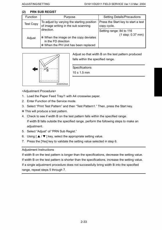
Di1611/Di2011 FIELD SERVICE Ver.1.0 Mar. 2004ADJUSTING/SETTING
(2) PRN SUB REGIST
<Adjustment Procedure>1. Load the Paper Feed Tray/1 with A4 crosswise paper.2. Enter Function of the Service mode.3. Select “Print Test Pattern” and then “Test Pattern1.” Then, press the Start key.✽ This will produce a test pattern.4. Check to see if width B on the test pattern falls within the specified range.
If width B falls outside the specified range, perform the following steps to make an adjustment.
5. Select “Adjust” of “PRN Sub Regist.”6. Using [ ▲ / ▼ ] key, select the appropriate setting value.7. Press the [Yes] key to validate the setting value selected in step 6.
Function Purpose Setting Details/Precautions
Test Copy To adjust by varying the starting position of image writing in the sub scanning direction.
✽ When the image on the copy deviates in the FD direction
✽ When the PH Unit has been replaced
Press the Start key to start a test copy cycle.
Adjust
Setting range: 84 to 116 (1 step: 0.37 mm)
Adjust so that width B on the test pattern produced falls within the specified range.
Specifications10 ± 1.5 mm
4035D520AA
B
2-33
Adjustment InstructionsIf width B on the test pattern is longer than the specifications, decrease the setting value.If width B on the test pattern is shorter than the specifications, increase the setting value.If a single adjustment procedure does not successfully bring width B into the specified range, repeat steps 5 through 7.
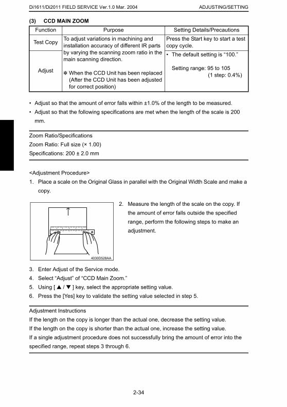
Di1611/Di2011 FIELD SERVICE Ver.1.0 Mar. 2004 ADJUSTING/SETTING
(3) CCD MAIN ZOOMFunction Purpose Setting Details/Precautions
• Adjust so that the amount of error falls within ±1.0% of the length to be measured.• Adjust so that the following specifications are met when the length of the scale is 200
mm.
Zoom Ratio/SpecificationsZoom Ratio: Full size (× 1.00)Specifications: 200 ± 2.0 mm
<Adjustment Procedure>1. Place a scale on the Original Glass in parallel with the Original Width Scale and make a
copy.
Test Copy To adjust variations in machining and installation accuracy of different IR parts by varying the scanning zoom ratio in the main scanning direction.
✽ When the CCD Unit has been replaced (After the CCD Unit has been adjusted for correct position)
Press the Start key to start a test copy cycle.
Adjust
• The default setting is “100.”
Setting range: 95 to 105 (1 step: 0.4%)
2. Measure the length of the scale on the copy. If the amount of error falls outside the specified range, perform the following steps to make an adjustment.
4030D528AA
2-34
3. Enter Adjust of the Service mode.4. Select “Adjust” of “CCD Main Zoom.”5. Using [ ▲ / ▼ ] key, select the appropriate setting value.6. Press the [Yes] key to validate the setting value selected in step 5.
Adjustment InstructionsIf the length on the copy is longer than the actual one, decrease the setting value.If the length on the copy is shorter than the actual one, increase the setting value.If a single adjustment procedure does not successfully bring the amount of error into the specified range, repeat steps 3 through 6.
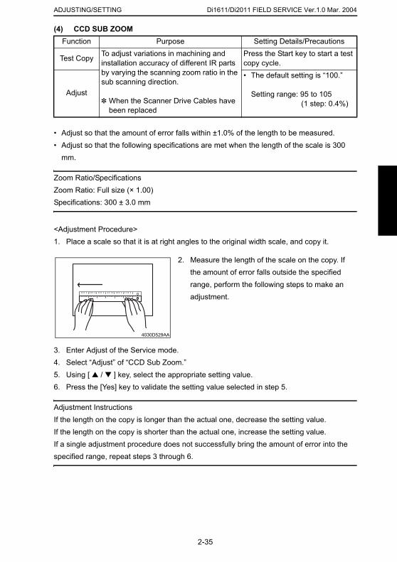
Di1611/Di2011 FIELD SERVICE Ver.1.0 Mar. 2004ADJUSTING/SETTING
(4) CCD SUB ZOOM
• Adjust so that the amount of error falls within ±1.0% of the length to be measured.• Adjust so that the following specifications are met when the length of the scale is 300
mm.
Zoom Ratio/SpecificationsZoom Ratio: Full size (× 1.00)Specifications: 300 ± 3.0 mm
<Adjustment Procedure>1. Place a scale so that it is at right angles to the original width scale, and copy it.
Function Purpose Setting Details/Precautions
Test Copy To adjust variations in machining and installation accuracy of different IR parts by varying the scanning zoom ratio in the sub scanning direction.
✽ When the Scanner Drive Cables have been replaced
Press the Start key to start a test copy cycle.
Adjust
• The default setting is “100.”
Setting range: 95 to 105 (1 step: 0.4%)
2. Measure the length of the scale on the copy. If the amount of error falls outside the specified range, perform the following steps to make an adjustment.
4030D529AA
2-35
3. Enter Adjust of the Service mode.4. Select “Adjust” of “CCD Sub Zoom.”5. Using [ ▲ / ▼ ] key, select the appropriate setting value.6. Press the [Yes] key to validate the setting value selected in step 5.
Adjustment InstructionsIf the length on the copy is longer than the actual one, decrease the setting value.If the length on the copy is shorter than the actual one, increase the setting value.If a single adjustment procedure does not successfully bring the amount of error into the specified range, repeat steps 3 through 6.
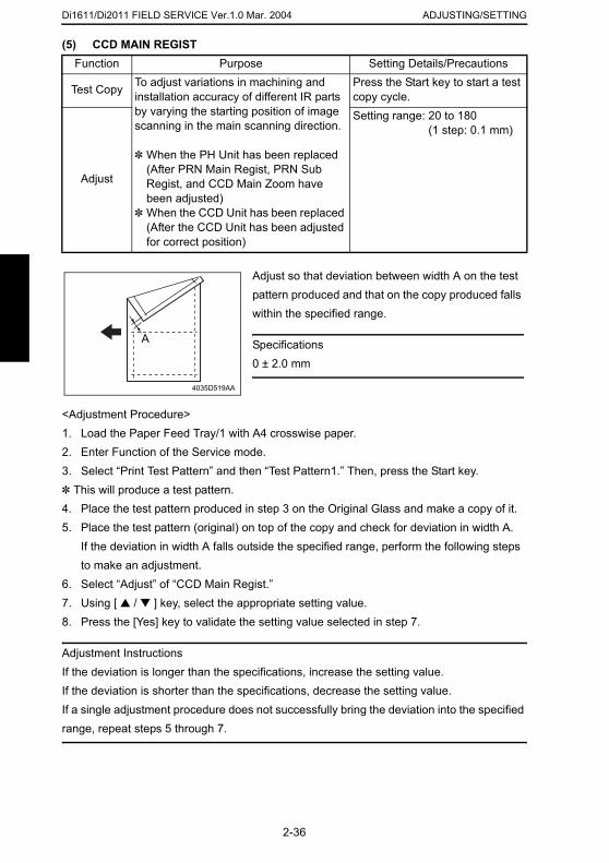
Di1611/Di2011 FIELD SERVICE Ver.1.0 Mar. 2004 ADJUSTING/SETTING
(5) CCD MAIN REGISTFunction Purpose Setting Details/Precautions
<Adjustment Procedure>1. Load the Paper Feed Tray/1 with A4 crosswise paper.2. Enter Function of the Service mode.3. Select “Print Test Pattern” and then “Test Pattern1.” Then, press the Start key.✽ This will produce a test pattern.4. Place the test pattern produced in step 3 on the Original Glass and make a copy of it.5. Place the test pattern (original) on top of the copy and check for deviation in width A.
If the deviation in width A falls outside the specified range, perform the following steps
Test Copy To adjust variations in machining and installation accuracy of different IR parts by varying the starting position of image scanning in the main scanning direction.
✽ When the PH Unit has been replaced (After PRN Main Regist, PRN Sub Regist, and CCD Main Zoom have been adjusted)
✽ When the CCD Unit has been replaced (After the CCD Unit has been adjusted for correct position)
Press the Start key to start a test copy cycle.
Adjust
Setting range: 20 to 180 (1 step: 0.1 mm)
Adjust so that deviation between width A on the test pattern produced and that on the copy produced falls within the specified range.
Specifications0 ± 2.0 mm
4035D519AA
A
2-36
to make an adjustment.6. Select “Adjust” of “CCD Main Regist.”7. Using [ ▲ / ▼ ] key, select the appropriate setting value.8. Press the [Yes] key to validate the setting value selected in step 7.
Adjustment InstructionsIf the deviation is longer than the specifications, increase the setting value.If the deviation is shorter than the specifications, decrease the setting value.If a single adjustment procedure does not successfully bring the deviation into the specified range, repeat steps 5 through 7.
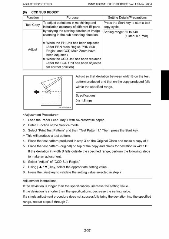
Di1611/Di2011 FIELD SERVICE Ver.1.0 Mar. 2004ADJUSTING/SETTING
(6) CCD SUB REGIST
<Adjustment Procedure>1. Load the Paper Feed Tray/1 with A4 crosswise paper.2. Enter Function of the Service mode.3. Select “Print Test Pattern” and then “Test Pattern1.” Then, press the Start key.✽ This will produce a test pattern.4. Place the test pattern produced in step 3 on the Original Glass and make a copy of it.5. Place the test pattern (original) on top of the copy and check for deviation in width B.
Function Purpose Setting Details/Precautions
Test Copy To adjust variations in machining and installation accuracy of different IR parts by varying the starting position of image scanning in the sub scanning direction.
✽ When the PH Unit has been replaced (After PRN Main Regist, PRN Sub Regist, and CCD Main Zoom have been adjusted)
✽ When the CCD Unit has been replaced (After the CCD Unit has been adjusted for correct position)
Press the Start key to start a test copy cycle.
Adjust
Setting range: 60 to 140 (1 step: 0.1 mm)
Adjust so that deviation between width B on the test pattern produced and that on the copy produced falls within the specified range.
Specifications0 ± 1.5 mm
4035D520AA
B
2-37
If the deviation in width B falls outside the specified range, perform the following steps to make an adjustment.
6. Select “Adjust” of “CCD Sub Regist.”7. Using [ ▲ / ▼ ] key, select the appropriate setting value.8. Press the [Yes] key to validate the setting value selected in step 7.
Adjustment InstructionsIf the deviation is longer than the specifications, increase the setting value.If the deviation is shorter than the specifications, decrease the setting value.If a single adjustment procedure does not successfully bring the deviation into the specified range, repeat steps 5 through 7.
Di1611/Di2011 FIELD SERVICE Ver.1.0 Mar. 2004 ADJUSTING/SETTING
(7) ADF SUB ZOOM✽ appears only when the AF-12 or AFR-19 (Di2011 Only) is installed
(8) ADF MAIN REGIST✽ appears only when the AF-12 or AFR-19 (Di2011 Only) is installed
(9) ADF SUB REGIST1✽ appears only when the AF-12 or AFR-19 (Di2011 Only) is installed
Function Purpose Setting Details/PrecautionsTest Copy To adjust variations in machining and
installation accuracy of different parts by varying the scanning zoom ratio in the sub scanning direction when the Auto-matic Document Feeder is used.
✽ Refer to the option service manual (AF-12, AFR-19) for details.
Adjust
Function Purpose Setting Details/PrecautionsTest Copy To adjust variations in machining and
installation accuracy of different parts by varying the scanning start position in the main scanning direction when the Auto-matic Document Feeder is used.
✽ Refer to the option service manual (AF-12, AFR-19) for details.
Adjust
Function Purpose Setting Details/PrecautionsTest Copy To adjust variations in machining and
installation accuracy of different parts by varying the scanning start position in the sub scanning direction when the Auto-matic Document Feeder is used.
NOTE• This adjustment should be made after
✽ Refer to the option service manual (AF-12, AFR-19) for details.
Adjust
2-38
the ADF Sub Zoom adjustment.
Di1611/Di2011 FIELD SERVICE Ver.1.0 Mar. 2004ADJUSTING/SETTING
(10) ADF SUB REGIST2
✽ appears only when the AFR-19 (Di2011 Only) is installed(11) ADF REG. LOOP1✽ appears only when the AFR-19 (Di2011 Only) is installed
(12) ADF REG. LOOP2✽ appears only when the AFR-19 (Di2011 Only) is installed
Function Purpose Setting Details/PrecautionsTest Copy To adjust variations in machining and
installation accuracy of different parts by varying the scanning start position in the sub scanning direction when the Auto-matic Document Feeder is used.
NOTE• This adjustment should be made after
the ADF Sub Zoom adjustment.
✽ Refer to the option service manual (AFR-19) for details.
Adjust
Purpose Setting Details/PrecautionsTo adjust the length of loop formed in the orig-inal before the Registration Roller.
✽ When a skew feed, fold, or misfeed of the original occurs
✽ Refer to the option service manual (AFR-19) for details.
Purpose Setting Details/PrecautionsTo adjust the length of loop formed in the orig-inal before the Registration Roller.
✽ When a skew feed, fold, or misfeed of the
✽ Refer to the option service manual (AFR-19) for details.
2-39
(13) ATDC GAIN
original occurs
Purpose Setting Details/PrecautionsTo manually adjust the ATDC Sensor voltage. • The default setting is “155.”
Setting range: 123 to 186
✽ The adjusted value of the ATDC Auto Adjust is the setting value.
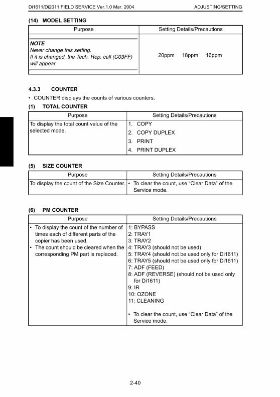
Di1611/Di2011 FIELD SERVICE Ver.1.0 Mar. 2004 ADJUSTING/SETTING
(14) MODEL SETTINGPurpose Setting Details/Precautions
4.3.3 COUNTER• COUNTER displays the counts of various counters.(1) TOTAL COUNTER
(5) SIZE COUNTER
(6) PM COUNTER
NOTENever change this setting.If it is changed, the Tech. Rep. call (C03FF) will appear.
20ppm 18ppm 16ppm
Purpose Setting Details/PrecautionsTo display the total count value of the selected mode.
1. COPY2. COPY DUPLEX3. PRINT4. PRINT DUPLEX
Purpose Setting Details/PrecautionsTo display the count of the Size Counter. • To clear the count, use “Clear Data” of the
Service mode.
Purpose Setting Details/Precautions• To display the count of the number of
times each of different parts of the copier has been used.
• The count should be cleared when the corresponding PM part is replaced.
1: BYPASS2: TRAY13: TRAY24: TRAY3 (should not be used)5: TRAY4 (should not be used only for Di1611)
2-40
6: TRAY5 (should not be used only for Di1611)7: ADF (FEED)8: ADF (REVERSE) (should not be used only
for Di1611)9: IR10: OZONE11: CLEANING
• To clear the count, use “Clear Data” of the Service mode.
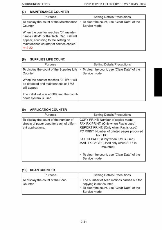
Di1611/Di2011 FIELD SERVICE Ver.1.0 Mar. 2004ADJUSTING/SETTING
(7) MAINTENANCE COUNTER
(8) SUPPLIES LIFE COUNT.
(9) APPLICATION COUNTER
Purpose Setting Details/PrecautionsTo display the count of the Maintenance Counter.
When the counter reaches “0”, mainte-nance call M1 or the Tech. Rep. call will appear, according to the setting on maintenance counter of service choice.☞ 2-22
• To clear the count, use “Clear Data” of the Service mode.
Purpose Setting Details/PrecautionsTo display the count of the Supplies Life Counter.
When the counter reaches “0”, life 1 will be detected and maintenance call M2 will appear.
The initial value is 40000, and the count-down system is used.
• To clear the count, use “Clear Data” of the Service mode.
Purpose Setting Details/PrecautionsTo display the count of the number of sheets of paper used for each of differ-ent applications.
COPY PRINT: Number of copies madeFAX RX PRINT: (Only when Fax is used)REPORT PRINT: (Only when Fax is used)PC PRINT: Number of printed pages produced
from PCFAX TX PAGE: (Only when Fax is used)
2-41
(10) SCAN COUNTER
MAIL TX PAGE: (Used only when SU-6 is mounted)
• To clear the count, use “Clear Data” of the Service mode.
Purpose Setting Details/PrecautionsTo display the count of the Scan Counter.
• The number of scan motions carried out for copying is not counted.
• To clear the count, use “Clear Data” of the Service mode.
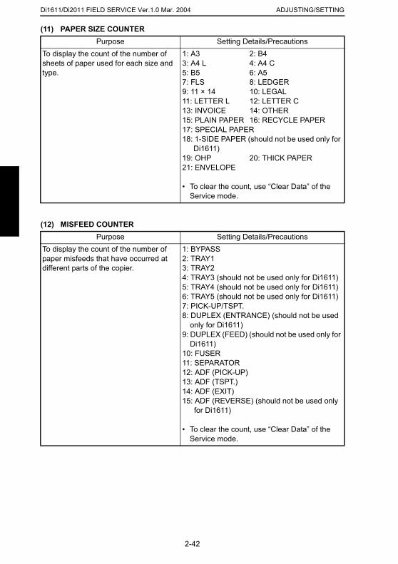
Di1611/Di2011 FIELD SERVICE Ver.1.0 Mar. 2004 ADJUSTING/SETTING
(11) PAPER SIZE COUNTERPurpose Setting Details/Precautions
(12) MISFEED COUNTER
To display the count of the number of sheets of paper used for each size and type.
1: A3 2: B43: A4 L 4: A4 C5: B5 6: A57: FLS 8: LEDGER9: 11 × 14 10: LEGAL11: LETTER L 12: LETTER C13: INVOICE 14: OTHER15: PLAIN PAPER 16: RECYCLE PAPER17: SPECIAL PAPER18: 1-SIDE PAPER (should not be used only for
Di1611)19: OHP 20: THICK PAPER21: ENVELOPE
• To clear the count, use “Clear Data” of the Service mode.
Purpose Setting Details/PrecautionsTo display the count of the number of paper misfeeds that have occurred at different parts of the copier.
1: BYPASS2: TRAY13: TRAY24: TRAY3 (should not be used only for Di1611)5: TRAY4 (should not be used only for Di1611)6: TRAY5 (should not be used only for Di1611)7: PICK-UP/TSPT.8: DUPLEX (ENTRANCE) (should not be used
only for Di1611)9: DUPLEX (FEED) (should not be used only for
Di1611)10: FUSER11: SEPARATOR
2-42
12: ADF (PICK-UP)13: ADF (TSPT.)14: ADF (EXIT)15: ADF (REVERSE) (should not be used only
for Di1611)
• To clear the count, use “Clear Data” of the Service mode.
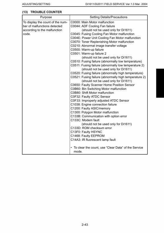
Di1611/Di2011 FIELD SERVICE Ver.1.0 Mar. 2004ADJUSTING/SETTING
(13) TROUBLE COUNTER
Purpose Setting Details/PrecautionsTo display the count of the num-ber of malfunctions detected according to the malfunction code.
C0000: Main Motor malfunctionC0044: ADF Cooling Fan failure
(should not be used only for Di1611)C0045: Fusing Cooling Fan Motor malfunctionC004E: Power Unit Cooling Fan Motor malfunctionC0070: Toner Replenishing Motor malfunctionC0210: Abnormal image transfer voltageC0500: Warm-up failureC0501: Warm-up failure 2
(should not be used only for Di1611)C0510: Fusing failure (abnormally low temperature)C0511: Fusing failure (abnormally low temperature 2)
(should not be used only for Di1611)C0520: Fusing failure (abnormally high temperature)C0521: Fusing failure (abnormally high temperature 2)
(should not be used only for Di1611)C0650: Faulty Scanner Home Position SensorC0B60: Bin Switching Motor malfunctionC0B80: Shift Motor malfunctionC0F32: Faulty ATDC SensorC0F33: Improperly adjusted ATDC SensorC1038: Engine connection failureC1200: Faulty ASIC/memoryC1300: Polygon Motor malfunctionC133B: Communication with option errorC133C: Modem fault
(should not be used only for Di1611)C133D: ROM checksum errorC13F0: Faulty HSYNCC1468: Faulty EEPROMC14A3: IR fluorescent lamp fault
2-43
• To clear the count, use “Clear Data” of the Service mode.
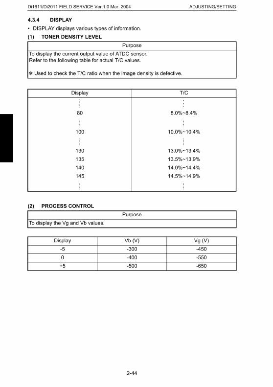
Di1611/Di2011 FIELD SERVICE Ver.1.0 Mar. 2004 ADJUSTING/SETTING
4.3.4 DISPLAY• DISPLAY displays various types of information.
(1) TONER DENSITY LEVEL(2) PROCESS CONTROL
PurposeTo display the current output value of ATDC sensor. Refer to the following table for actual T/C values.
✽ Used to check the T/C ratio when the image density is defective.
Display T/C
······
·····
80 8.0%~8.4%
·····
·····
100 10.0%~10.4%
·····
·····
130 13.0%~13.4%135 13.5%~13.9%140 14.0%~14.4%145 14.5%~14.9%
·····
·····
PurposeTo display the Vg and Vb values.
Display Vb (V) Vg (V)-5 -300 -450
2-44
0 -400 -550+5 -500 -650
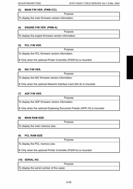
Di1611/Di2011 FIELD SERVICE Ver.1.0 Mar. 2004ADJUSTING/SETTING
(3) MAIN F/W VER. (PWB-C/C)
(4) ENGINE F/W VER. (PWB-A)
(5) PCL F/W VER.
(6) NIC F/W VER.
(7) ADF F/W VER.
PurposeTo display the main firmware version information.
PurposeTo display the engine firmware version information.
PurposeTo display the PCL firmware version information.
✽ Only when the optional Printer Controller (Pi2001e) is mounted
PurposeTo display the NIC firmware version information.
✽ Only when the optional Network Interface Card (NC-6) is mounted
PurposeTo display the ADF firmware version information.
✽ Only when the optional Duplexing Document Feeder (AFR-19) is mounted
2-45
(8) MAIN RAM SIZE
(9) PCL RAM SIZE
(10) SERIAL NO.
PurposeTo display the main memory size.
PurposeTo display the PCL memory size.
✽ Only when the optional Printer Controller (Pi2001e) is mounted
PurposeTo display the serial number of the copier.
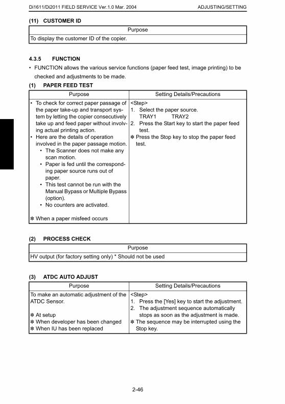
Di1611/Di2011 FIELD SERVICE Ver.1.0 Mar. 2004 ADJUSTING/SETTING
(11) CUSTOMER IDPurpose
4.3.5 FUNCTION• FUNCTION allows the various service functions (paper feed test, image printing) to be
checked and adjustments to be made.(1) PAPER FEED TEST
(2) PROCESS CHECK
To display the customer ID of the copier.
Purpose Setting Details/Precautions• To check for correct paper passage of
the paper take-up and transport sys-tem by letting the copier consecutively take up and feed paper without involv-ing actual printing action.
• Here are the details of operation involved in the paper passage motion.
• The Scanner does not make any scan motion.
• Paper is fed until the correspond-ing paper source runs out of paper.
• This test cannot be run with the Manual Bypass or Multiple Bypass (option).
• No counters are activated.
✽ When a paper misfeed occurs
<Step>1. Select the paper source.
TRAY1 TRAY22. Press the Start key to start the paper feed
test.✽ Press the Stop key to stop the paper feed
test.
PurposeHV output (for factory setting only) * Should not be used
2-46
(3) ATDC AUTO ADJUSTPurpose Setting Details/Precautions
To make an automatic adjustment of the ATDC Sensor.
✽ At setup✽ When developer has been changed✽ When IU has been replaced
<Step>1. Press the [Yes] key to start the adjustment.2. The adjustment sequence automatically
stops as soon as the adjustment is made.✽ The sequence may be interrupted using the
Stop key.
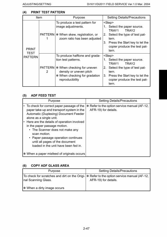
Di1611/Di2011 FIELD SERVICE Ver.1.0 Mar. 2004ADJUSTING/SETTING
(4) PRINT TEST PATTERN
(5) ADF FEED TEST
Item Purpose Setting Details/Precautions
PRINT TEST
PATTERN
PATTERN1
To produce a test pattern for image adjustments.
✽ When skew, registration, or zoom ratio has been adjusted
<Step>1. Select the paper source.
TRAY1 TRAY22. Select the type of test pat-
tern.3. Press the Start key to let the
copier produce the test pat-tern.
PATTERN2
To produce halftone and grada-tion test patterns.
✽ When checking for uneven density or uneven pitch
✽ When checking for gradation reproducibility
<Step>1. Select the paper source.
TRAY1 TRAY22. Select the type of test pat-
tern.3. Press the Start key to let the
copier produce the test pat-tern.
Purpose Setting Details/Precautions• To check for correct paper passage of the
paper take-up and transport system in the Automatic (Duplexing) Document Feeder alone as a single unit.
• Here are the details of operation involved in the paper passage motion.
• The Scanner does not make any scan motion.
• Paper passage operation continues until all pages of the document loaded in the unit have been fed in.
✽ Refer to the option service manual (AF-12, AFR-19) for details.
2-47
(6) COPY ADF GLASS AREA
✽ When a paper misfeed of originals occurs
Purpose Setting Details/PrecautionsTo check for scratches and dirt on the Origi-nal Scanning Glass.
✽ When a dirty image occurs
✽ Refer to the option service manual (AF-12, AFR-19) for details.
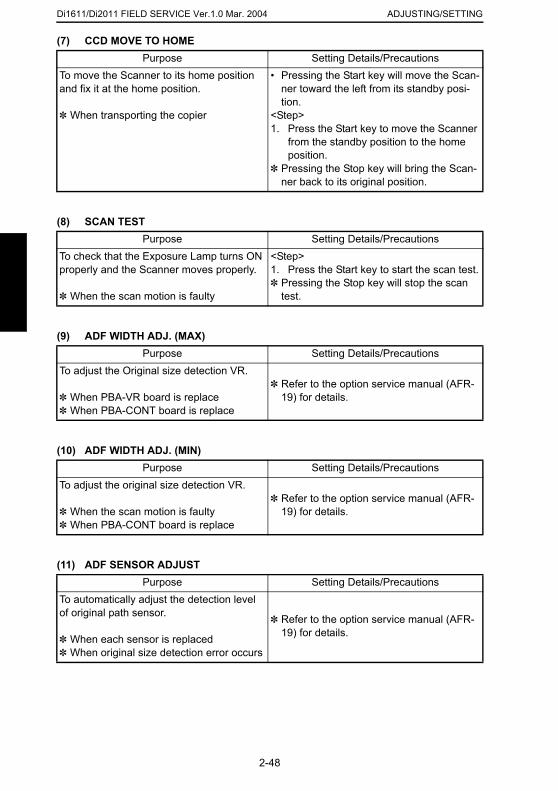
Di1611/Di2011 FIELD SERVICE Ver.1.0 Mar. 2004 ADJUSTING/SETTING
(7) CCD MOVE TO HOMEPurpose Setting Details/Precautions
(8) SCAN TEST
(9) ADF WIDTH ADJ. (MAX)
(10) ADF WIDTH ADJ. (MIN)
To move the Scanner to its home position and fix it at the home position.
✽ When transporting the copier
• Pressing the Start key will move the Scan-ner toward the left from its standby posi-tion.
<Step>1. Press the Start key to move the Scanner
from the standby position to the home position.
✽ Pressing the Stop key will bring the Scan-ner back to its original position.
Purpose Setting Details/PrecautionsTo check that the Exposure Lamp turns ON properly and the Scanner moves properly.
✽ When the scan motion is faulty
<Step>1. Press the Start key to start the scan test.✽ Pressing the Stop key will stop the scan
test.
Purpose Setting Details/PrecautionsTo adjust the Original size detection VR.
✽ When PBA-VR board is replace✽ When PBA-CONT board is replace
✽ Refer to the option service manual (AFR-19) for details.
Purpose Setting Details/PrecautionsTo adjust the original size detection VR.
✽ Refer to the option service manual (AFR-
2-48
(11) ADF SENSOR ADJUST
✽ When the scan motion is faulty✽ When PBA-CONT board is replace
19) for details.
Purpose Setting Details/PrecautionsTo automatically adjust the detection level of original path sensor.
✽ When each sensor is replaced✽ When original size detection error occurs
✽ Refer to the option service manual (AFR-19) for details.

Di1611/Di2011 FIELD SERVICE Ver.1.0 Mar. 2004ADJUSTING/SETTING
4.3.6 ADMIN. REGISTRATION
• ADMINISTRATOR NUMBER REGISTRATION is used to register or change the adminis-trator number required when entering the Admin. Management function of the Utility mode.
<Step>1. Using the 10-Key Pad, type the 6-digit administrator number (000000 to 999999) to be
registered or changed.2. Press the [Yes] key to register the administrator number.
2-49
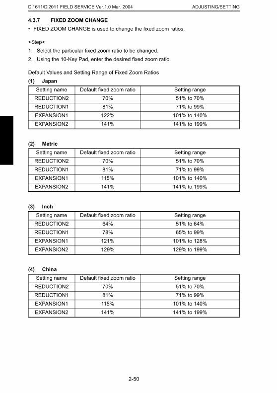
Di1611/Di2011 FIELD SERVICE Ver.1.0 Mar. 2004 ADJUSTING/SETTING
4.3.7 FIXED ZOOM CHANGE• FIXED ZOOM CHANGE is used to change the fixed zoom ratios.
<Step>1. Select the particular fixed zoom ratio to be changed.2. Using the 10-Key Pad, enter the desired fixed zoom ratio.
Default Values and Setting Range of Fixed Zoom Ratios(1) Japan
(2) Metric
(3) Inch
Setting name Default fixed zoom ratio Setting rangeREDUCTION2 70% 51% to 70%REDUCTION1 81% 71% to 99%EXPANSION1 122% 101% to 140%EXPANSION2 141% 141% to 199%
Setting name Default fixed zoom ratio Setting rangeREDUCTION2 70% 51% to 70%REDUCTION1 81% 71% to 99%EXPANSION1 115% 101% to 140%EXPANSION2 141% 141% to 199%
Setting name Default fixed zoom ratio Setting rangeREDUCTION2 64% 51% to 64%REDUCTION1 78% 65% to 99%EXPANSION1 121% 101% to 128%EXPANSION2 129% 129% to 199%
2-50
(4) ChinaSetting name Default fixed zoom ratio Setting range
REDUCTION2 70% 51% to 70%REDUCTION1 81% 71% to 99%EXPANSION1 115% 101% to 140%EXPANSION2 141% 141% to 199%
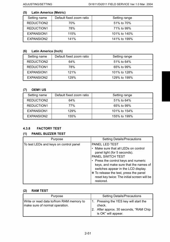
Di1611/Di2011 FIELD SERVICE Ver.1.0 Mar. 2004ADJUSTING/SETTING
(5) Latin America (Metric)
(6) Latin America (Inch)
(7) OEM1 US
4.3.8 FACTORY TEST(1) PANEL BUZZER TEST
Setting name Default fixed zoom ratio Setting rangeREDUCTION2 70% 51% to 70%REDUCTION1 78% 71% to 99%EXPANSION1 115% 101% to 140%EXPANSION2 141% 141% to 199%
Setting name Default fixed zoom ratio Setting rangeREDUCTION2 64% 51% to 64%REDUCTION1 78% 65% to 99%EXPANSION1 121% 101% to 128%EXPANSION2 129% 129% to 199%
Setting name Default fixed zoom ratio Setting rangeREDUCTION2 64% 51% to 64%REDUCTION1 77% 65% to 99%EXPANSION1 129% 101% to 154%EXPANSION2 155% 155% to 199%
Purpose Setting Details/PrecautionsTo test LEDs and keys on control panel PANEL LED TEST
• Make sure that all LEDs on control
2-51
(2) RAM TEST
panel light (for 5 seconds).PANEL SWITCH TEST• Press the control keys and numeric
keys, and make sure that the names of switches appear in the LCD display.
✽ To release the test, press the panel reset key twice: The initial screen will be restored.
Purpose Setting Details/PrecautionsWrite or read data to/from RAM memory to make sure of normal operation.
1. Pressing the YES key will start the check.
2. After approx. 30 seconds, “RAM Chip is OK” will appear.
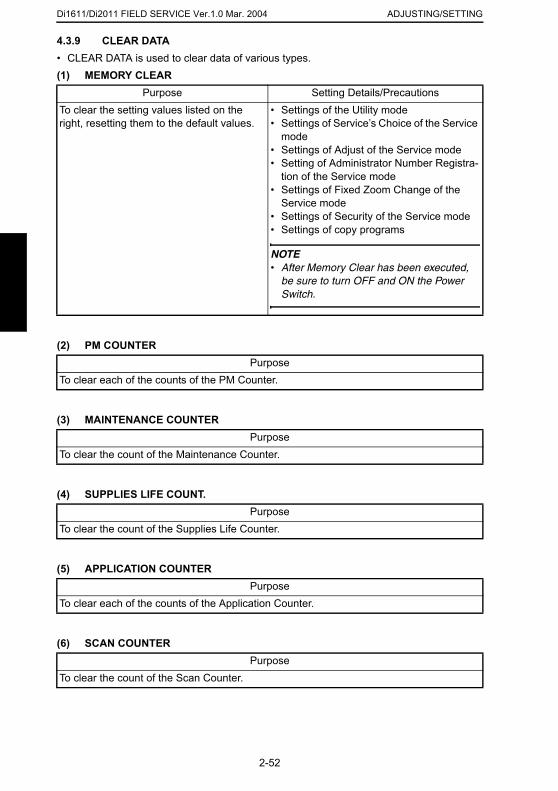
Di1611/Di2011 FIELD SERVICE Ver.1.0 Mar. 2004 ADJUSTING/SETTING
4.3.9 CLEAR DATA• CLEAR DATA is used to clear data of various types.
(1) MEMORY CLEAR(2) PM COUNTER
(3) MAINTENANCE COUNTER
(4) SUPPLIES LIFE COUNT.
Purpose Setting Details/PrecautionsTo clear the setting values listed on the right, resetting them to the default values.
• Settings of the Utility mode• Settings of Service’s Choice of the Service
mode• Settings of Adjust of the Service mode• Setting of Administrator Number Registra-
tion of the Service mode• Settings of Fixed Zoom Change of the
Service mode• Settings of Security of the Service mode• Settings of copy programs
NOTE• After Memory Clear has been executed,
be sure to turn OFF and ON the Power Switch.
PurposeTo clear each of the counts of the PM Counter.
PurposeTo clear the count of the Maintenance Counter.
2-52
(5) APPLICATION COUNTER
(6) SCAN COUNTER
PurposeTo clear the count of the Supplies Life Counter.
PurposeTo clear each of the counts of the Application Counter.
PurposeTo clear the count of the Scan Counter.

Di1611/Di2011 FIELD SERVICE Ver.1.0 Mar. 2004ADJUSTING/SETTING
(7) PAPER SIZE COUNTER
(8) MISFEED COUNTER
(9) TROUBLE COUNTER
(10) ADF BACKUP CLEAR (Di2011 Only)
4.3.10 SECURITY• SECURITY is used to set the security functions.
<Security Function Setting Procedure>1. Call the Service mode to the screen.
PurposeTo clear each of the counts of the Paper Size Counter.
PurposeTo clear each of the counts of the Misfeed Counter.
PurposeTo clear each of the counts of the Trouble Counter.
Purpose Setting Details/PrecautionsTo clear the values adjusted with ADF SEN-SOR ADJUST and the values adjusted with Org. Width Detect.
✽ When PBA-CONT board has been replaced.
✽ When PBA-VR board has been replaced.
✽ Refer to the option service manual (AFR-19) for details.
2-53
2. Press the following keys in this order:Stop → 9
3. The Security mode screen will appear.
(1) TOTAL COUNTER COUNTPurpose Setting Details/Precautions
To set the count-up method. • The default setting is “0.”
0: One count-up for each copy cycle (ordi-nary mode)
1: Multiple count-up according to the paper size and copy mode.
2: Multiple count-up according to the paper size and copy mode.
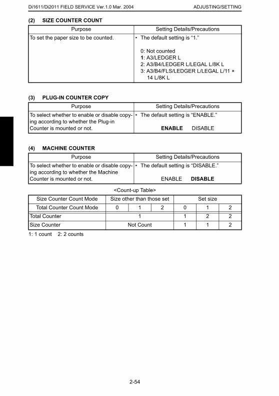
Di1611/Di2011 FIELD SERVICE Ver.1.0 Mar. 2004 ADJUSTING/SETTING
(2) SIZE COUNTER COUNTPurpose Setting Details/Precautions
(3) PLUG-IN COUNTER COPY
(4) MACHINE COUNTER
<Count-up Table>
1: 1 count 2: 2 counts
To set the paper size to be counted. • The default setting is “1.”
0: Not counted1: A3/LEDGER L2: A3/B4/LEDGER L/LEGAL L/8K L3: A3/B4/FLS/LEDGER L/LEGAL L/11 ×
14 L/8K L
Purpose Setting Details/PrecautionsTo select whether to enable or disable copy-ing according to whether the Plug-in Counter is mounted or not.
• The default setting is “ENABLE.”
ENABLE DISABLE
Purpose Setting Details/PrecautionsTo select whether to enable or disable copy-ing according to whether the Machine Counter is mounted or not.
• The default setting is “DISABLE.”
ENABLE DISABLE
Size Counter Count Mode Size other than those set Set sizeTotal Counter Count Mode 0 1 2 0 1 2
Total Counter 1 1 2 2Size Counter Not Count 1 1 2
2-54
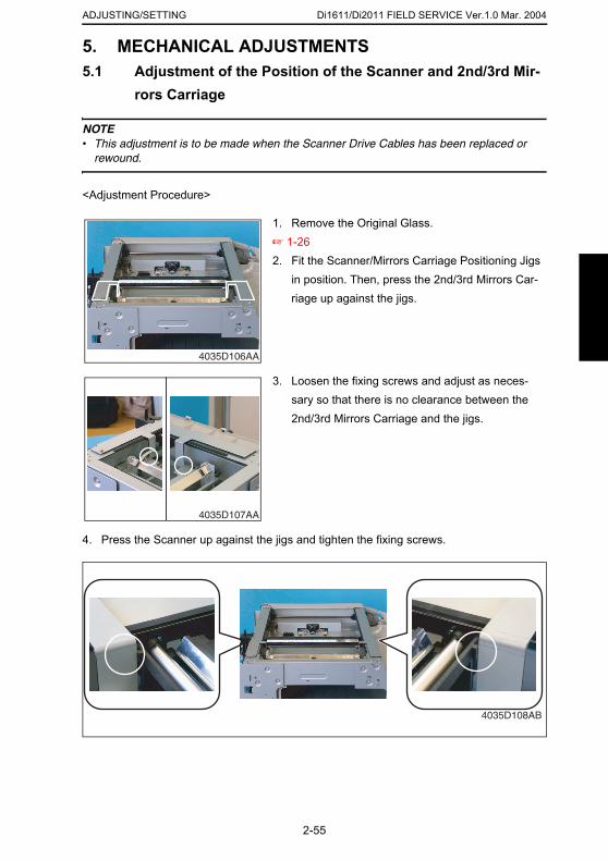
Di1611/Di2011 FIELD SERVICE Ver.1.0 Mar. 2004ADJUSTING/SETTING
5. MECHANICAL ADJUSTMENTS5.1 Adjustment of the Position of the Scanner and 2nd/3rd Mir-
rors Carriage
NOTE• This adjustment is to be made when the Scanner Drive Cables has been replaced or
rewound.
<Adjustment Procedure>
1. Remove the Original Glass.☞ 1-262. Fit the Scanner/Mirrors Carriage Positioning Jigs
in position. Then, press the 2nd/3rd Mirrors Car-riage up against the jigs.
4035D106AA
3. Loosen the fixing screws and adjust as neces-sary so that there is no clearance between the 2nd/3rd Mirrors Carriage and the jigs.
4035D107AA
2-55
4. Press the Scanner up against the jigs and tighten the fixing screws.
4035D108AB
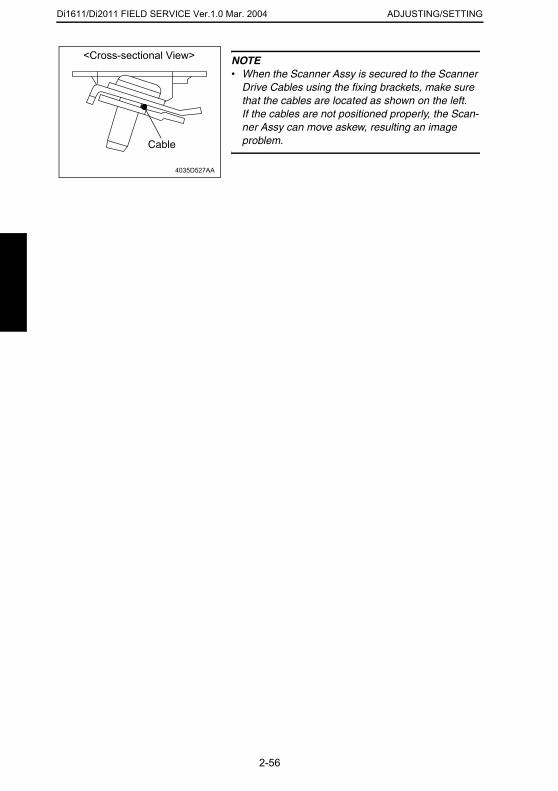
Di1611/Di2011 FIELD SERVICE Ver.1.0 Mar. 2004 ADJUSTING/SETTING
<Cross-sectional View>
NOTE• When the Scanner Assy is secured to the ScannerDrive Cables using the fixing brackets, make sure that the cables are located as shown on the left.If the cables are not positioned properly, the Scan-ner Assy can move askew, resulting an image problem.
4035D527AA
Cable
2-56
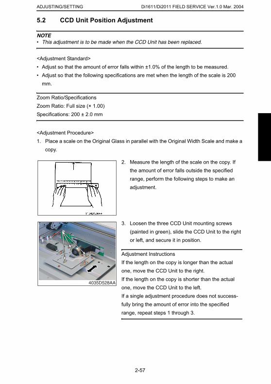
Di1611/Di2011 FIELD SERVICE Ver.1.0 Mar. 2004ADJUSTING/SETTING
5.2 CCD Unit Position Adjustment
NOTE• This adjustment is to be made when the CCD Unit has been replaced.
<Adjustment Standard>• Adjust so that the amount of error falls within ±1.0% of the length to be measured.• Adjust so that the following specifications are met when the length of the scale is 200
mm.
Zoom Ratio/SpecificationsZoom Ratio: Full size (× 1.00)Specifications: 200 ± 2.0 mm
<Adjustment Procedure>1. Place a scale on the Original Glass in parallel with the Original Width Scale and make a
copy.
2. Measure the length of the scale on the copy. If the amount of error falls outside the specified range, perform the following steps to make an adjustment.
3. Loosen the three CCD Unit mounting screws (painted in green), slide the CCD Unit to the right
2-57
or left, and secure it in position.
Adjustment InstructionsIf the length on the copy is longer than the actual one, move the CCD Unit to the right.If the length on the copy is shorter than the actual one, move the CCD Unit to the left.If a single adjustment procedure does not success-fully bring the amount of error into the specified range, repeat steps 1 through 3.
4035D528AA
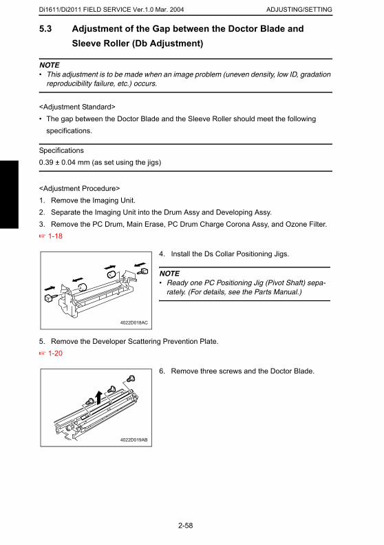
Di1611/Di2011 FIELD SERVICE Ver.1.0 Mar. 2004 ADJUSTING/SETTING
5.3 Adjustment of the Gap between the Doctor Blade and
Sleeve Roller (Db Adjustment)NOTE• This adjustment is to be made when an image problem (uneven density, low ID, gradation
reproducibility failure, etc.) occurs.
<Adjustment Standard>• The gap between the Doctor Blade and the Sleeve Roller should meet the following
specifications.
Specifications0.39 ± 0.04 mm (as set using the jigs)
<Adjustment Procedure>1. Remove the Imaging Unit.2. Separate the Imaging Unit into the Drum Assy and Developing Assy.3. Remove the PC Drum, Main Erase, PC Drum Charge Corona Assy, and Ozone Filter.☞ 1-18
5. Remove the Developer Scattering Prevention Plate.
4. Install the Ds Collar Positioning Jigs.
NOTE• Ready one PC Positioning Jig (Pivot Shaft) sepa-
rately. (For details, see the Parts Manual.)
4022D018AC
2-58
☞ 1-20
6. Remove three screws and the Doctor Blade.
4022D019AB
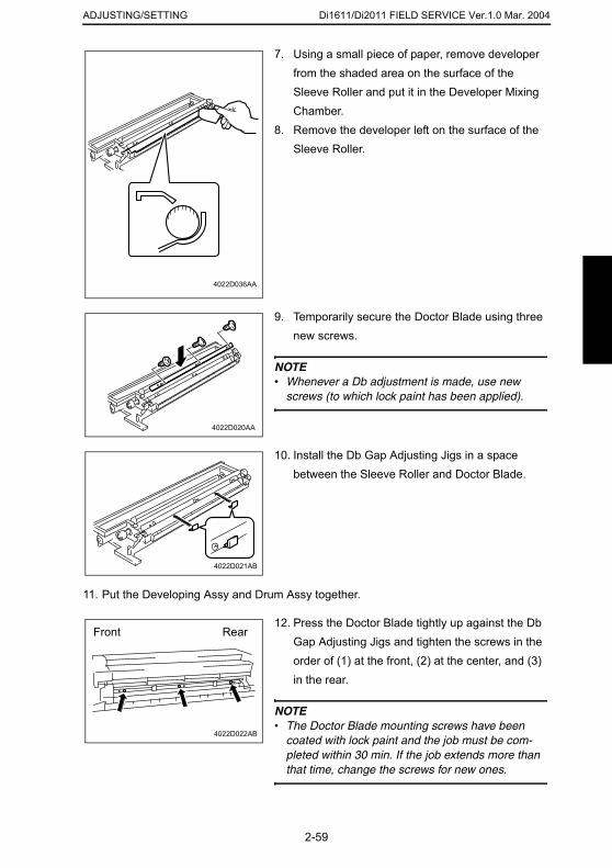
Di1611/Di2011 FIELD SERVICE Ver.1.0 Mar. 2004ADJUSTING/SETTING
7. Using a small piece of paper, remove developer from the shaded area on the surface of the Sleeve Roller and put it in the Developer Mixing Chamber.
8. Remove the developer left on the surface of the Sleeve Roller.
4022D036AA
9. Temporarily secure the Doctor Blade using three new screws.
NOTE• Whenever a Db adjustment is made, use new
screws (to which lock paint has been applied).
4022D020AA
10. Install the Db Gap Adjusting Jigs in a space between the Sleeve Roller and Doctor Blade.
2-59
11. Put the Developing Assy and Drum Assy together.
4022D021AB
12. Press the Doctor Blade tightly up against the Db Gap Adjusting Jigs and tighten the screws in the order of (1) at the front, (2) at the center, and (3) in the rear.
NOTE• The Doctor Blade mounting screws have been
coated with lock paint and the job must be com-pleted within 30 min. If the job extends more than that time, change the screws for new ones.
4022D022AB
Front Rear
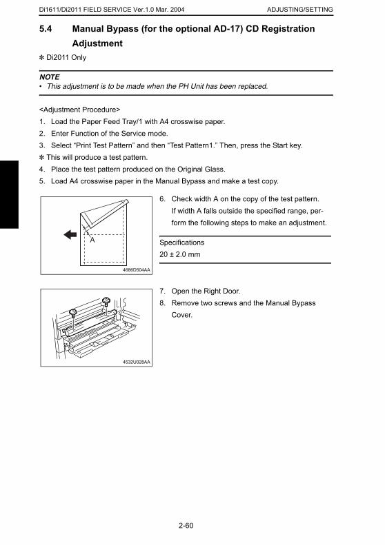
Di1611/Di2011 FIELD SERVICE Ver.1.0 Mar. 2004 ADJUSTING/SETTING
5.4 Manual Bypass (for the optional AD-17) CD Registration
Adjustment✽ Di2011 Only
NOTE• This adjustment is to be made when the PH Unit has been replaced.
<Adjustment Procedure>1. Load the Paper Feed Tray/1 with A4 crosswise paper.2. Enter Function of the Service mode.3. Select “Print Test Pattern” and then “Test Pattern1.” Then, press the Start key.✽ This will produce a test pattern.4. Place the test pattern produced on the Original Glass.5. Load A4 crosswise paper in the Manual Bypass and make a test copy.
6. Check width A on the copy of the test pattern.If width A falls outside the specified range, per-form the following steps to make an adjustment.
Specifications20 ± 2.0 mm
A
4686D504AA
7. Open the Right Door.8. Remove two screws and the Manual Bypass
Cover.
2-60
4532U028AA
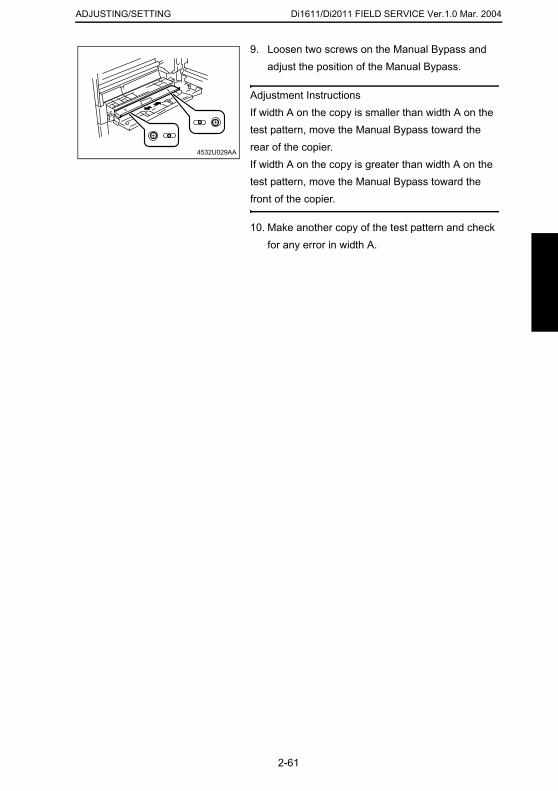
Di1611/Di2011 FIELD SERVICE Ver.1.0 Mar. 2004ADJUSTING/SETTING
9. Loosen two screws on the Manual Bypass and adjust the position of the Manual Bypass.
Adjustment InstructionsIf width A on the copy is smaller than width A on the test pattern, move the Manual Bypass toward the rear of the copier.If width A on the copy is greater than width A on the test pattern, move the Manual Bypass toward the front of the copier.
10. Make another copy of the test pattern and check for any error in width A.
4532U029AA
2-61

Di1611/Di2011 FIELD SERVICE Ver.1.0 Mar. 2004 ADJUSTING/SETTING
2-62

TROUBLESHOOTING
19971
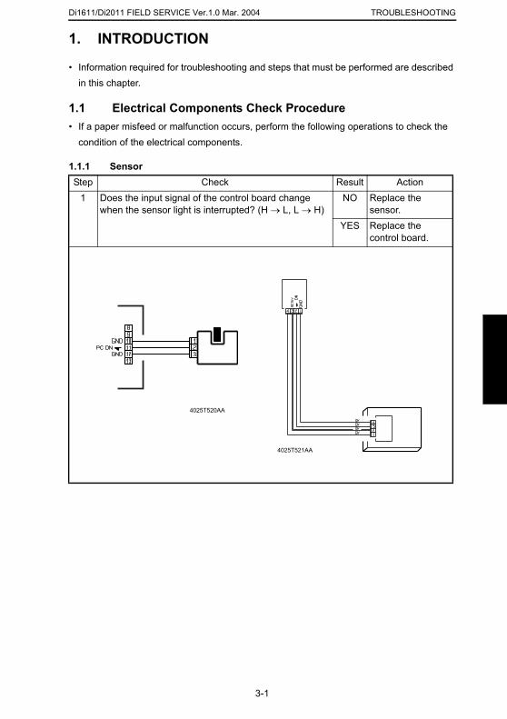
Di1611/Di2011 FIELD SERVICE Ver.1.0 Mar. 2004 TROUBLESHOOTING
1. INTRODUCTION
• Information required for troubleshooting and steps that must be performed are described in this chapter.
1.1 Electrical Components Check Procedure• If a paper misfeed or malfunction occurs, perform the following operations to check the
condition of the electrical components.
1.1.1 SensorStep Check Result Action
1 Does the input signal of the control board change when the sensor light is interrupted? (H → L, L → H)
NO Replace the sensor.
YES Replace the control board.
4025T520AA
3-1
4025T521AA

Di1611/Di2011 FIELD SERVICE Ver.1.0 Mar. 2004TROUBLESHOOTING
1.1.2 SwitchStep Check Result Action
1.1.3 Solenoid
1 Does the input signal (NO) of the control board change from L to H when the switch is activated?
NO Replace the switch.
YES Replace the control board.
Step Check Result Action1 Does the output signal of the control board change
from H to L when the solenoid is activated?NO Replace the
control board.YES Replace the
solenoid.
Not UseCOM
NO
4025T523AB
12
212
1
4025T522AA
3-2
1.1.4 ClutchStep Check Result Action
1 Does the output signal of the control board change from H to L when the clutch is activated?
NO Replace the control board.
YES Replace the clutch.
4025T528AA
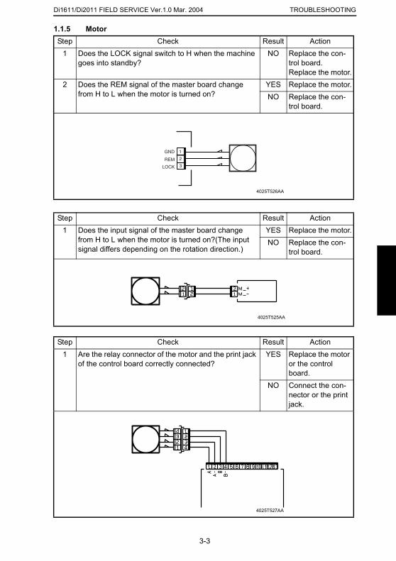
Di1611/Di2011 FIELD SERVICE Ver.1.0 Mar. 2004 TROUBLESHOOTING
1.1.5 Motor
Step Check Result Action1 Does the LOCK signal switch to H when the machine goes into standby?
NO Replace the con-trol board. Replace the motor.
2 Does the REM signal of the master board change from H to L when the motor is turned on?
YES Replace the motor.NO Replace the con-
trol board.
Step Check Result Action1 Does the input signal of the master board change
from H to L when the motor is turned on?(The input signal differs depending on the rotation direction.)
YES Replace the motor.NO Replace the con-
trol board.
Step Check Result Action
GND
REM
LOCK
2
1
3
4025T526AA
4025T525AA
3-3
1 Are the relay connector of the motor and the print jack of the control board correctly connected?
YES Replace the motor or the control board.
NO Connect the con-nector or the print jack.
4025T527AA
Di1611/Di2011 FIELD SERVICE Ver.1.0 Mar. 2004TROUBLESHOOTING
2. MISFEEDS
2.1 Initial Checks• When a paper misfeed occurs, first perform the following initial checks.2.2 Paper Misfeed Detection2.2.1 Outline
• A paper misfeed is detected by detecting different states of signals (H, L) of several sen-sors located near the paper take-up section and the Exit Paper Sensor. The copier thereby determines whether there is paper left inside it.
• The timings of the rising and falling edges of the paper take-up-related sensors and the Exit Paper Sensor are monitored to detect a misfeed of paper being fed through the copier.
• The states (H, L) of the paper take-up-related sensors and the Exit Paper Sensor are
Check Item ActionDoes paper meet product specifications? Replace paper.Is the paper curled, wavy, or damp? Replace paper.
Instruct the user on the correct paper storage procedures.
Is a foreign object present along the paper path, or is the paper path deformed or worn?
Clean or change the paper path.
Are the Paper Separator Fingers dirty, deformed, or worn?
Clean or replace the defective Paper Separator Finger.
Are rolls/rollers dirty, deformed, or worn? Clean or replace the defective roll/roller.Are the Edge Guide and Trailing Edge Stop at the correct position to accommodate the paper?
Set as necessary.
Are the actuators operational and checked for correct operation?
Correct or replace the defective actua-tor.
3-4
monitored to detect a sheet of paper left in the copier.• All drives are brought to a stop when a sheet of paper misfed or left in the copier is
detected.
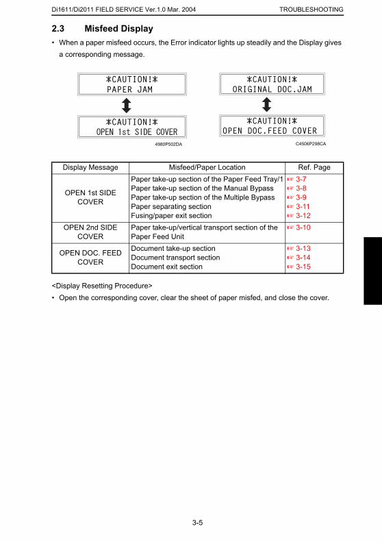
Di1611/Di2011 FIELD SERVICE Ver.1.0 Mar. 2004 TROUBLESHOOTING
2.3 Misfeed Display• When a paper misfeed occurs, the Error indicator lights up steadily and the Display gives
a corresponding message.
<Display Resetting Procedure>• Open the corresponding cover, clear the sheet of paper misfed, and close the cover.
Display Message Misfeed/Paper Location Ref. Page
OPEN 1st SIDE COVER
Paper take-up section of the Paper Feed Tray/1Paper take-up section of the Manual BypassPaper take-up section of the Multiple BypassPaper separating sectionFusing/paper exit section
☞ 3-7☞ 3-8☞ 3-9☞ 3-11☞ 3-12
OPEN 2nd SIDE COVER
Paper take-up/vertical transport section of the Paper Feed Unit
☞ 3-10
OPEN DOC. FEED COVER
Document take-up sectionDocument transport sectionDocument exit section
☞ 3-13☞ 3-14☞ 3-15
4980P502DA C4506P298CA
3-5
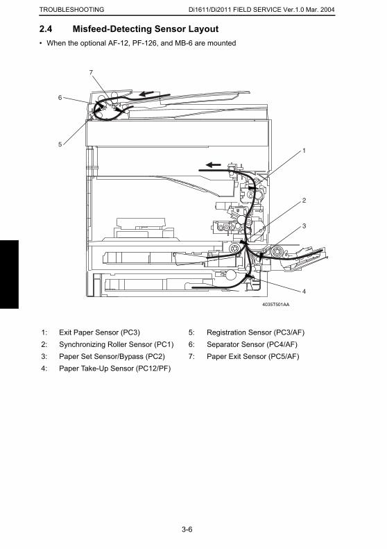
Di1611/Di2011 FIELD SERVICE Ver.1.0 Mar. 2004TROUBLESHOOTING
2.4 Misfeed-Detecting Sensor Layout
• When the optional AF-12, PF-126, and MB-6 are mounted1: Exit Paper Sensor (PC3) 5: Registration Sensor (PC3/AF)2: Synchronizing Roller Sensor (PC1) 6: Separator Sensor (PC4/AF)
1
2
5
6
7
3
4
4035T501AA
3-6
3: Paper Set Sensor/Bypass (PC2) 7: Paper Exit Sensor (PC5/AF)4: Paper Take-Up Sensor (PC12/PF)
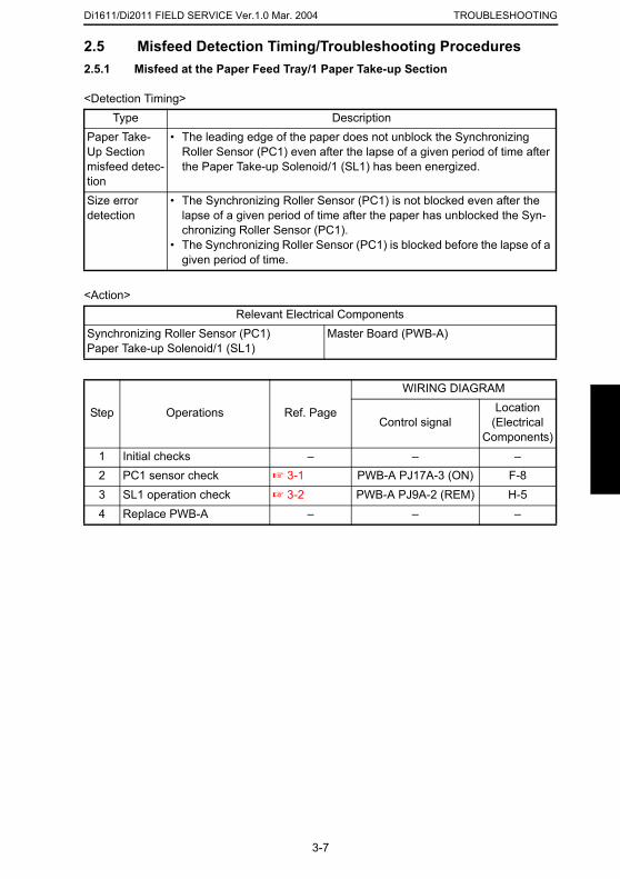
Di1611/Di2011 FIELD SERVICE Ver.1.0 Mar. 2004 TROUBLESHOOTING
2.5 Misfeed Detection Timing/Troubleshooting Procedures2.5.1 Misfeed at the Paper Feed Tray/1 Paper Take-up Section
<Detection Timing>
<Action>
Type DescriptionPaper Take-Up Section misfeed detec-tion
• The leading edge of the paper does not unblock the Synchronizing Roller Sensor (PC1) even after the lapse of a given period of time after the Paper Take-up Solenoid/1 (SL1) has been energized.
Size error detection
• The Synchronizing Roller Sensor (PC1) is not blocked even after the lapse of a given period of time after the paper has unblocked the Syn-chronizing Roller Sensor (PC1).
• The Synchronizing Roller Sensor (PC1) is blocked before the lapse of a given period of time.
Relevant Electrical ComponentsSynchronizing Roller Sensor (PC1)Paper Take-up Solenoid/1 (SL1)
Master Board (PWB-A)
Step Operations Ref. Page
WIRING DIAGRAM
Control signalLocation
(Electrical Components)
1 Initial checks – – –2 PC1 sensor check ☞ 3-1 PWB-A PJ17A-3 (ON) F-83 SL1 operation check ☞ 3-2 PWB-A PJ9A-2 (REM) H-54 Replace PWB-A – – –
3-7
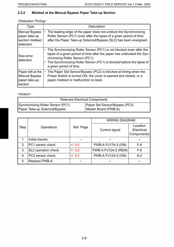
Di1611/Di2011 FIELD SERVICE Ver.1.0 Mar. 2004TROUBLESHOOTING
2.5.2 Misfeed at the Manual Bypass Paper Take-up Section
<Detection Timing>
<Action>
Type DescriptionManual Bypass paper take-up section misfeed detection
• The leading edge of the paper does not unblock the Synchronizing Roller Sensor (PC1) even after the lapse of a given period of time after the Paper Take-up Solenoid/Bypass (SL2) has been energized.
Size error detection
• The Synchronizing Roller Sensor (PC1) is not blocked even after the lapse of a given period of time after the paper has unblocked the Syn-chronizing Roller Sensor (PC1).
• The Synchronizing Roller Sensor (PC1) is blocked before the lapse of a given period of time.
Paper left at the Manual Bypass paper take-up section
• The Paper Set Sensor/Bypass (PC2) is blocked at timing when the Power Switch is turned ON, the cover is opened and closed, or a paper misfeed or malfunction is reset.
Relevant Electrical ComponentsSynchronizing Roller Sensor (PC1)Paper Take-up Solenoid/Bypass
Paper Set Sensor/Bypass (PC2)Master Board (PWB-A)
Step Operations Ref. Page
WIRING DIAGRAM
Control signalLocation
(Electrical Components)
1 Initial checks – – –2 PC1 sensor check ☞ 3-1 PWB-A PJ17A-3 (ON) F-83 SL2 operation check ☞ 3-2 PWB-A PJ12A-2 (REM) F-64 PC2 sensor check ☞ 3-1 PWB-A PJ12A-5 (ON) A-2
3-8
5 Replace PWB-A – – –
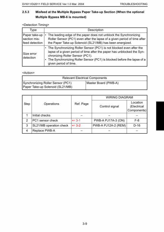
Di1611/Di2011 FIELD SERVICE Ver.1.0 Mar. 2004 TROUBLESHOOTING
2.5.3 Misfeed at the Multiple Bypass Paper Take-up Section (When the optional
Multiple Bypass MB-6 is mounted)<Detection Timing>
<Action>
Type DescriptionPaper take-up section mis-feed detection
• The leading edge of the paper does not unblock the Synchronizing Roller Sensor (PC1) even after the lapse of a given period of time after the Paper Take-up Solenoid (SL21/MB) has been energized.
Size error detection
• The Synchronizing Roller Sensor (PC1) is not blocked even after the lapse of a given period of time after the paper has unblocked the Syn-chronizing Roller Sensor (PC1).
• The Synchronizing Roller Sensor (PC1) is blocked before the lapse of a given period of time.
Relevant Electrical ComponentsSynchronizing Roller Sensor (PC1)Paper Take-up Solenoid (SL21/MB)
Master Board (PWB-A)
Step Operations Ref. Page
WIRING DIAGRAM
Control signalLocation
(Electrical Components)
1 Initial checks – – –2 PC1 sensor check ☞ 3-1 PWB-A PJ17A-3 (ON) F-83 SL21/MB operation check ☞ 3-2 PWB-A PJ12A-2 (REM) D-164 Replace PWB-A – – –
3-9
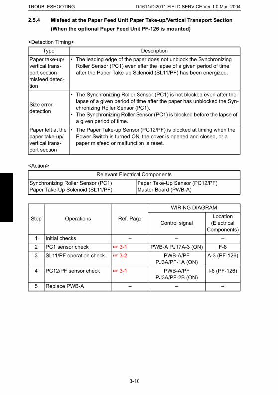
Di1611/Di2011 FIELD SERVICE Ver.1.0 Mar. 2004TROUBLESHOOTING
2.5.4 Misfeed at the Paper Feed Unit Paper Take-up/Vertical Transport Section (When the optional Paper Feed Unit PF-126 is mounted)
<Detection Timing>
<Action>
Type DescriptionPaper take-up/vertical trans-port section misfeed detec-tion
• The leading edge of the paper does not unblock the Synchronizing Roller Sensor (PC1) even after the lapse of a given period of time after the Paper Take-up Solenoid (SL11/PF) has been energized.
Size error detection
• The Synchronizing Roller Sensor (PC1) is not blocked even after the lapse of a given period of time after the paper has unblocked the Syn-chronizing Roller Sensor (PC1).
• The Synchronizing Roller Sensor (PC1) is blocked before the lapse of a given period of time.
Paper left at the paper take-up/vertical trans-port section
• The Paper Take-up Sensor (PC12/PF) is blocked at timing when the Power Switch is turned ON, the cover is opened and closed, or a paper misfeed or malfunction is reset.
Relevant Electrical ComponentsSynchronizing Roller Sensor (PC1)Paper Take-Up Solenoid (SL11/PF)
Paper Take-Up Sensor (PC12/PF)Master Board (PWB-A)
Step Operations Ref. Page
WIRING DIAGRAM
Control signalLocation
(Electrical Components)
1 Initial checks – – –2 PC1 sensor check ☞ 3-1 PWB-A PJ17A-3 (ON) F-8
3-10
3 SL11/PF operation check ☞ 3-2 PWB-A/PF PJ3A/PF-1A (ON)
A-3 (PF-126)
4 PC12/PF sensor check ☞ 3-1 PWB-A/PF PJ3A/PF-2B (ON)
I-6 (PF-126)
5 Replace PWB-A – – –
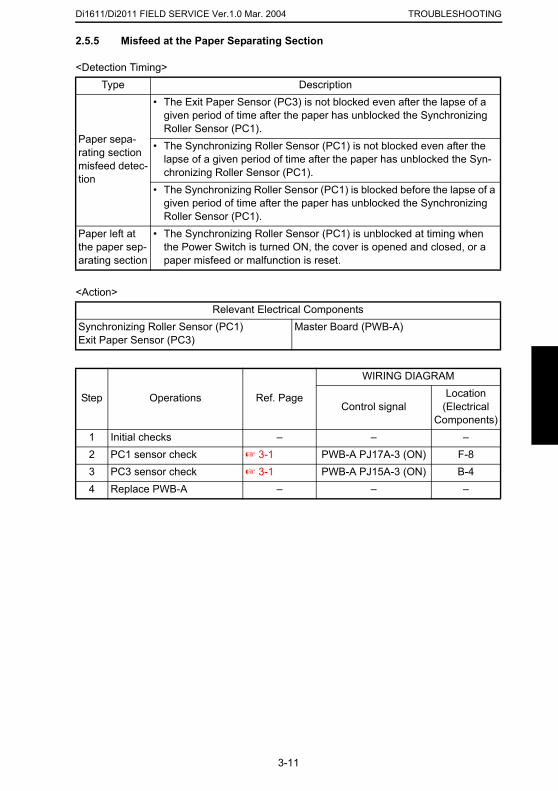
Di1611/Di2011 FIELD SERVICE Ver.1.0 Mar. 2004 TROUBLESHOOTING
2.5.5 Misfeed at the Paper Separating Section
<Detection Timing>
<Action>
Type Description
Paper sepa-rating section misfeed detec-tion
• The Exit Paper Sensor (PC3) is not blocked even after the lapse of a given period of time after the paper has unblocked the Synchronizing Roller Sensor (PC1).
• The Synchronizing Roller Sensor (PC1) is not blocked even after the lapse of a given period of time after the paper has unblocked the Syn-chronizing Roller Sensor (PC1).
• The Synchronizing Roller Sensor (PC1) is blocked before the lapse of a given period of time after the paper has unblocked the Synchronizing Roller Sensor (PC1).
Paper left at the paper sep-arating section
• The Synchronizing Roller Sensor (PC1) is unblocked at timing when the Power Switch is turned ON, the cover is opened and closed, or a paper misfeed or malfunction is reset.
Relevant Electrical ComponentsSynchronizing Roller Sensor (PC1)Exit Paper Sensor (PC3)
Master Board (PWB-A)
Step Operations Ref. Page
WIRING DIAGRAM
Control signalLocation
(Electrical Components)
1 Initial checks – – –2 PC1 sensor check ☞ 3-1 PWB-A PJ17A-3 (ON) F-83 PC3 sensor check ☞ 3-1 PWB-A PJ15A-3 (ON) B-44 Replace PWB-A – – –
3-11
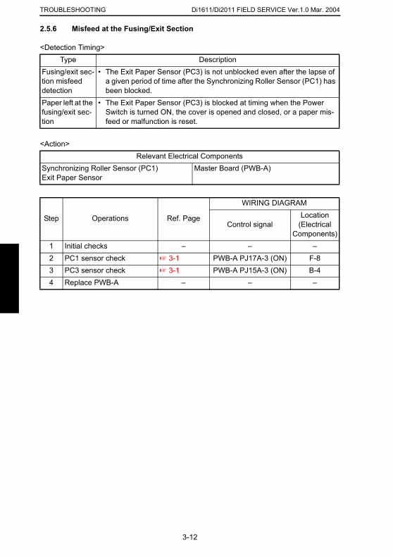
Di1611/Di2011 FIELD SERVICE Ver.1.0 Mar. 2004TROUBLESHOOTING
2.5.6 Misfeed at the Fusing/Exit Section
<Detection Timing>
<Action>
Type DescriptionFusing/exit sec-tion misfeed detection
• The Exit Paper Sensor (PC3) is not unblocked even after the lapse of a given period of time after the Synchronizing Roller Sensor (PC1) has been blocked.
Paper left at the fusing/exit sec-tion
• The Exit Paper Sensor (PC3) is blocked at timing when the Power Switch is turned ON, the cover is opened and closed, or a paper mis-feed or malfunction is reset.
Relevant Electrical ComponentsSynchronizing Roller Sensor (PC1)Exit Paper Sensor
Master Board (PWB-A)
Step Operations Ref. Page
WIRING DIAGRAM
Control signalLocation
(Electrical Components)
1 Initial checks – – –2 PC1 sensor check ☞ 3-1 PWB-A PJ17A-3 (ON) F-83 PC3 sensor check ☞ 3-1 PWB-A PJ15A-3 (ON) B-44 Replace PWB-A – – –
3-12
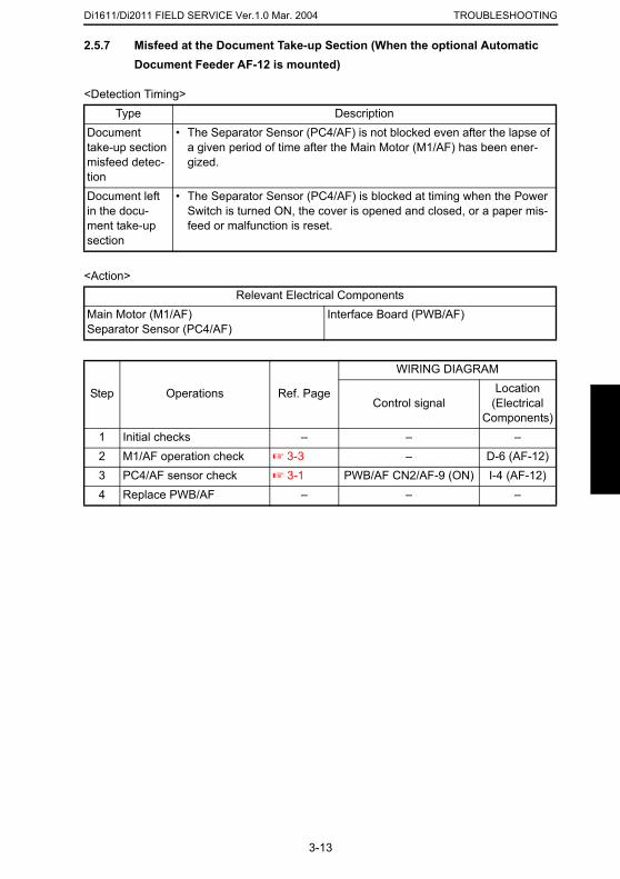
Di1611/Di2011 FIELD SERVICE Ver.1.0 Mar. 2004 TROUBLESHOOTING
2.5.7 Misfeed at the Document Take-up Section (When the optional Automatic
Document Feeder AF-12 is mounted)<Detection Timing>
<Action>
Type DescriptionDocument take-up section misfeed detec-tion
• The Separator Sensor (PC4/AF) is not blocked even after the lapse of a given period of time after the Main Motor (M1/AF) has been ener-gized.
Document left in the docu-ment take-up section
• The Separator Sensor (PC4/AF) is blocked at timing when the Power Switch is turned ON, the cover is opened and closed, or a paper mis-feed or malfunction is reset.
Relevant Electrical ComponentsMain Motor (M1/AF)Separator Sensor (PC4/AF)
Interface Board (PWB/AF)
Step Operations Ref. Page
WIRING DIAGRAM
Control signalLocation
(Electrical Components)
1 Initial checks – – –2 M1/AF operation check ☞ 3-3 – D-6 (AF-12)3 PC4/AF sensor check ☞ 3-1 PWB/AF CN2/AF-9 (ON) I-4 (AF-12)4 Replace PWB/AF – – –
3-13
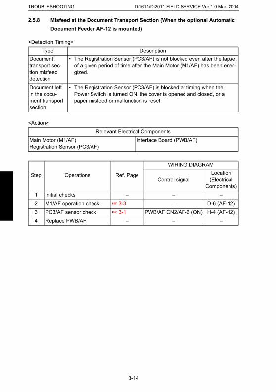
Di1611/Di2011 FIELD SERVICE Ver.1.0 Mar. 2004TROUBLESHOOTING
2.5.8 Misfeed at the Document Transport Section (When the optional Automatic Document Feeder AF-12 is mounted)
<Detection Timing>
<Action>
Type DescriptionDocument transport sec-tion misfeed detection
• The Registration Sensor (PC3/AF) is not blocked even after the lapse of a given period of time after the Main Motor (M1/AF) has been ener-gized.
Document left in the docu-ment transport section
• The Registration Sensor (PC3/AF) is blocked at timing when the Power Switch is turned ON, the cover is opened and closed, or a paper misfeed or malfunction is reset.
Relevant Electrical ComponentsMain Motor (M1/AF)Registration Sensor (PC3/AF)
Interface Board (PWB/AF)
Step Operations Ref. Page
WIRING DIAGRAM
Control signalLocation
(Electrical Components)
1 Initial checks – – –2 M1/AF operation check ☞ 3-3 – D-6 (AF-12)3 PC3/AF sensor check ☞ 3-1 PWB/AF CN2/AF-6 (ON) H-4 (AF-12)4 Replace PWB/AF – – –
3-14
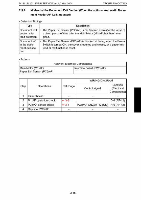
Di1611/Di2011 FIELD SERVICE Ver.1.0 Mar. 2004 TROUBLESHOOTING
2.5.9 Misfeed at the Document Exit Section (When the optional Automatic Docu-
ment Feeder AF-12 is mounted)<Detection Timing>
<Action>
Type DescriptionDocument exit section mis-feed detection
• The Paper Exit Sensor (PC5/AF) is not blocked even after the lapse of a given period of time after the Main Motor (M1/AF) has been ener-gized.
Document left in the docu-ment exit sec-tion
• The Paper Exit Sensor (PC5/AF) is blocked at timing when the Power Switch is turned ON, the cover is opened and closed, or a paper mis-feed or malfunction is reset.
Relevant Electrical ComponentsMain Motor (M1/AF)Paper Exit Sensor (PC5/AF)
Interface Board (PWB/AF)
Step Operations Ref. Page
WIRING DIAGRAM
Control signalLocation
(Electrical Components)
1 Initial checks – – –2 M1/AF operation check ☞ 3-3 – D-6 (AF-12)3 PC5/AF sensor check ☞ 3-1 PWB/AF CN2/AF-12 (ON) H-6 (AF-12)4 Replace PWB/AF – – –
3-15

Di1611/Di2011 FIELD SERVICE Ver.1.0 Mar. 2004TROUBLESHOOTING
3. MALFUNCTIONS
• The copier’s CPU performs a self-diagnostics function that, on detecting a malfunction,gives the corresponding malfunction code and maintenance call mark on the Touch Panel.
3.1 List of Malfunction CodesMalfunc-
tion Code
Malfunction Name Detection Timing
C0000 Main Motor mal-function
• The Main Motor (M1) Lock signal remains HIGH for a continuous 1-sec. period at any time 1 sec. after the Main Motor has started turning.
C0044
ADF Cooling Fan Failure (Only when the optional AFR-19 is mounted)
• Refer to the option service manual (AFR-19) for details.
C0045 Fusing Cooling Fan Motor malfunction
• The Fusing Cooling Fan Motor (M3) Lock signal remains HIGH for a continuous 1-sec. period while the Fusing Cooling Fan Motor is turning at full speed or decelerated speed.
• The Power Supply Cooling Fan Motor (M4) Lock signal
4980P550DA
3-16
C004EPower Supply Cooling Fan Motor malfunction
remains HIGH for a continuous 1-sec. period while the Power Supply Cooling Fan Motor Remote signal remains ON (for full-speed rotation) or OFF (for deceler-ated-speed rotation).
C0070Toner Replenish-ing Motor malfunc-tion
• The Toner Bottle Home Position Sensor (PC7) outputs a HIGH signal for a continuous 3.5-sec. period while the Toner Bottle is turning.
• The Toner Bottle Home Position Sensor (PC7) outputs a LOW signal for a continuous 2-sec. period while the Toner Bottle is turning.
C0210 Abnormal image transfer voltage
• The image transfer voltage remains more than 100 V continuously for a given period of time while the PC Drum remains stationary.
C03FF Faulty Model Set-ting
• “Model Setting” of “Adjust” available from the Service mode is incorrectly set.
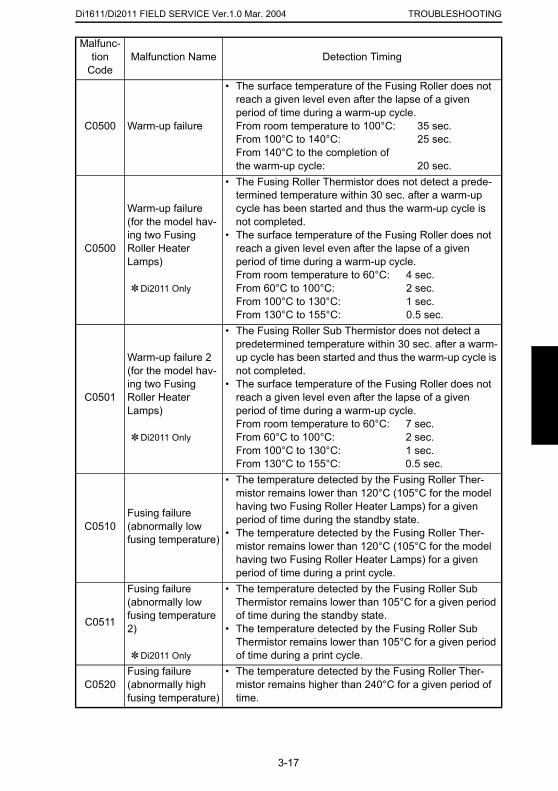
Di1611/Di2011 FIELD SERVICE Ver.1.0 Mar. 2004 TROUBLESHOOTING
C0500 Warm-up failure
• The surface temperature of the Fusing Roller does not reach a given level even after the lapse of a given period of time during a warm-up cycle.From room temperature to 100°C: 35 sec.From 100°C to 140°C: 25 sec.From 140°C to the completion of the warm-up cycle: 20 sec.
C0500
Warm-up failure (for the model hav-ing two Fusing Roller Heater Lamps)
✽ Di2011 Only
• The Fusing Roller Thermistor does not detect a prede-termined temperature within 30 sec. after a warm-up cycle has been started and thus the warm-up cycle is not completed.
• The surface temperature of the Fusing Roller does not reach a given level even after the lapse of a given period of time during a warm-up cycle.From room temperature to 60°C: 4 sec.From 60°C to 100°C: 2 sec.From 100°C to 130°C: 1 sec.From 130°C to 155°C: 0.5 sec.
C0501
Warm-up failure 2 (for the model hav-ing two Fusing Roller Heater Lamps)
✽ Di2011 Only
• The Fusing Roller Sub Thermistor does not detect a predetermined temperature within 30 sec. after a warm-up cycle has been started and thus the warm-up cycle is not completed.
• The surface temperature of the Fusing Roller does not reach a given level even after the lapse of a given period of time during a warm-up cycle.From room temperature to 60°C: 7 sec.From 60°C to 100°C: 2 sec.From 100°C to 130°C: 1 sec.From 130°C to 155°C: 0.5 sec.
• The temperature detected by the Fusing Roller Ther-
Malfunc-tion
CodeMalfunction Name Detection Timing
3-17
C0510Fusing failure (abnormally low fusing temperature)
mistor remains lower than 120°C (105°C for the model having two Fusing Roller Heater Lamps) for a given period of time during the standby state.
• The temperature detected by the Fusing Roller Ther-mistor remains lower than 120°C (105°C for the model having two Fusing Roller Heater Lamps) for a given period of time during a print cycle.
C0511
Fusing failure (abnormally low fusing temperature 2)
✽ Di2011 Only
• The temperature detected by the Fusing Roller Sub Thermistor remains lower than 105°C for a given period of time during the standby state.
• The temperature detected by the Fusing Roller Sub Thermistor remains lower than 105°C for a given period of time during a print cycle.
C0520Fusing failure (abnormally high fusing temperature)
• The temperature detected by the Fusing Roller Ther-mistor remains higher than 240°C for a given period of time.
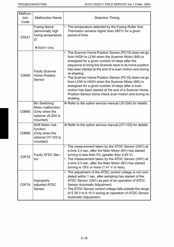
Di1611/Di2011 FIELD SERVICE Ver.1.0 Mar. 2004TROUBLESHOOTING
Malfunc-tion Malfunction Name Detection Timing
C0521
Fusing failure (abnormally high fusing temperature 2)
✽ Di2011 Only
• The temperature detected by the Fusing Roller Sub Thermistor remains higher than 240°C for a given period of time.
C0650Faulty Scanner Home Position Sensor
• The Scanner Home Position Sensor (PC10) does not go from HIGH to LOW when the Scanner Motor (M5) is energized for a given number of steps after the sequence to bring the Scanner back to its home position has been started at the end of a scan motion and during re-shading.
• The Scanner Home Position Sensor (PC10) does not go from LOW to HIGH when the Scanner Motor (M5) is energized for a given number of steps after a scan motion has been started at the end of a Scanner Home Position Sensor home check scan motion and during re-shading.
C0B60
Bin Switching Motor malfunction(Only when the optional JS-204 is mounted)
✽ Refer to the option service manual (JS-204) for details.
C0B80
Shift Motor mal-function(Only when the optional OT-103 is mounted)
✽ Refer to the option service manual (OT-103) for details.
C0F32 Faulty ATDC Sen-sor
• The measurement taken by the ATDC Sensor (UN1) at a time 2.0 sec. after the Main Motor (M1) has started turning is less than 5% (greater than 4.63 V).
• The measurement taken by the ATDC Sensor (UN1) at
Code
3-18
a time 2.0 sec. after the Main Motor (M1) has started turning is 19% or more (1.41 V or less).
C0F33Improperly adjusted ATDC Sensor
• The adjustment of the ATDC control voltage is not com-pleted within 1 sec. after sampling has started of the ATDC Sensor (UN1) as part of an operation of ATDC Sensor Automatic Adjustment.
• The ATDC Sensor control voltage falls outside the range of 5.39 V to 8.15 V during an operation of ATDC Sensor Automatic Adjustment.
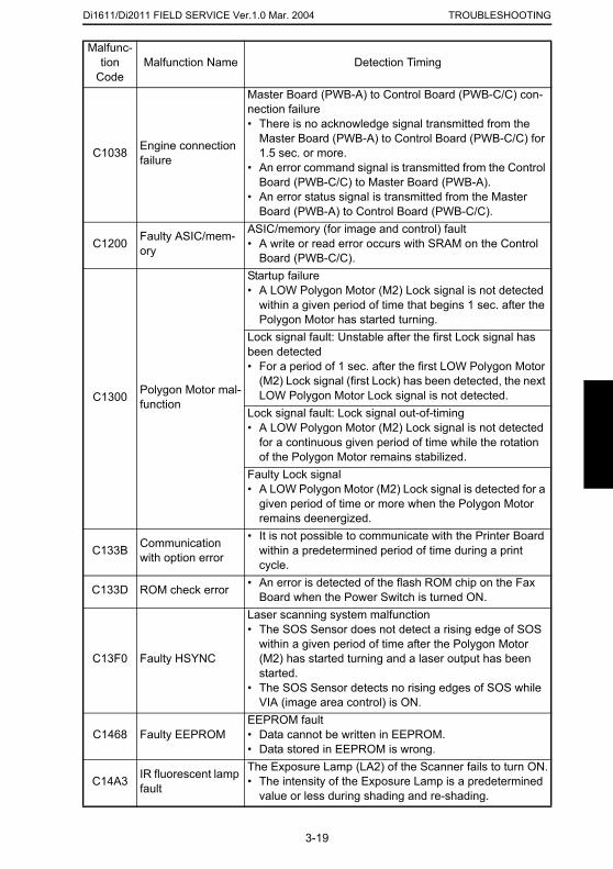
Di1611/Di2011 FIELD SERVICE Ver.1.0 Mar. 2004 TROUBLESHOOTING
C1038 Engine connection failure
Master Board (PWB-A) to Control Board (PWB-C/C) con-nection failure• There is no acknowledge signal transmitted from the
Master Board (PWB-A) to Control Board (PWB-C/C) for 1.5 sec. or more.
• An error command signal is transmitted from the Control Board (PWB-C/C) to Master Board (PWB-A).
• An error status signal is transmitted from the Master Board (PWB-A) to Control Board (PWB-C/C).
C1200 Faulty ASIC/mem-ory
ASIC/memory (for image and control) fault• A write or read error occurs with SRAM on the Control
Board (PWB-C/C).
C1300 Polygon Motor mal-function
Startup failure• A LOW Polygon Motor (M2) Lock signal is not detected
within a given period of time that begins 1 sec. after the Polygon Motor has started turning.
Lock signal fault: Unstable after the first Lock signal has been detected• For a period of 1 sec. after the first LOW Polygon Motor
(M2) Lock signal (first Lock) has been detected, the next LOW Polygon Motor Lock signal is not detected.
Lock signal fault: Lock signal out-of-timing• A LOW Polygon Motor (M2) Lock signal is not detected
for a continuous given period of time while the rotation of the Polygon Motor remains stabilized.
Faulty Lock signal• A LOW Polygon Motor (M2) Lock signal is detected for a
given period of time or more when the Polygon Motor remains deenergized.
• It is not possible to communicate with the Printer Board
Malfunc-tion
CodeMalfunction Name Detection Timing
3-19
C133B Communication with option error within a predetermined period of time during a print
cycle.
C133D ROM check error • An error is detected of the flash ROM chip on the Fax Board when the Power Switch is turned ON.
C13F0 Faulty HSYNC
Laser scanning system malfunction• The SOS Sensor does not detect a rising edge of SOS
within a given period of time after the Polygon Motor (M2) has started turning and a laser output has been started.
• The SOS Sensor detects no rising edges of SOS while VIA (image area control) is ON.
C1468 Faulty EEPROMEEPROM fault• Data cannot be written in EEPROM.• Data stored in EEPROM is wrong.
C14A3 IR fluorescent lamp fault
The Exposure Lamp (LA2) of the Scanner fails to turn ON.• The intensity of the Exposure Lamp is a predetermined
value or less during shading and re-shading.
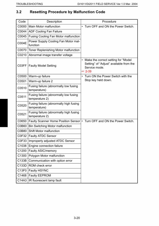
Di1611/Di2011 FIELD SERVICE Ver.1.0 Mar. 2004TROUBLESHOOTING
3.2 Resetting Procedure by Malfunction Code
Code Description ProcedureC0000 Main Motor malfunction • Turn OFF and ON the Power Switch.C0044 ADF Cooling Fan FailureC0045 Fusing Cooling Fan Motor malfunction
C004E Power Supply Cooling Fan Motor mal-function
C0070 Toner Replenishing Motor malfunctionC0210 Abnormal image transfer voltage
C03FF Faulty Model Setting
• Make the correct setting for “Model Setting” of “Adjust” available from the Service mode.
☞ 2-39C0500 Warm-up failure • Turn ON the Power Switch with the
Stop key held down.C0501 Warm-up failure 2
C0510 Fusing failure (abnormally low fusing temperature)
C0511 Fusing failure (abnormally low fusing temperature 2)
C0520 Fusing failure (abnormally high fusing temperature)
C0521 Fusing failure (abnormally high fusing temperature 2)
C0650 Faulty Scanner Home Position Sensor • Turn OFF and ON the Power Switch.C0B60 Bin Switching Motor malfunctionC0B80 Shift Motor malfunctionC0F32 Faulty ATDC SensorC0F33 Improperly adjusted ATDC Sensor
3-20
C1038 Engine connection failureC1200 Faulty ASIC/memoryC1300 Polygon Motor malfunctionC133B Communication with option errorC133D ROM check errorC13F0 Faulty HSYNCC1468 Faulty EEPROMC14A3 IR fluorescent lamp fault
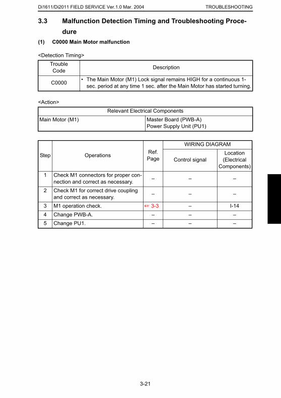
Di1611/Di2011 FIELD SERVICE Ver.1.0 Mar. 2004 TROUBLESHOOTING
3.3 Malfunction Detection Timing and Troubleshooting Proce-dure
(1) C0000 Main Motor malfunction
<Detection Timing>
<Action>
TroubleCode Description
C0000 • The Main Motor (M1) Lock signal remains HIGH for a continuous 1-sec. period at any time 1 sec. after the Main Motor has started turning.
Relevant Electrical ComponentsMain Motor (M1) Master Board (PWB-A)
Power Supply Unit (PU1)
Step Operations Ref. Page
WIRING DIAGRAM
Control signalLocation
(Electrical Components)
1 Check M1 connectors for proper con-nection and correct as necessary. – – –
2 Check M1 for correct drive coupling and correct as necessary. – – –
3 M1 operation check. ☞ 3-3 – I-144 Change PWB-A. – – –5 Change PU1. – – –
3-21
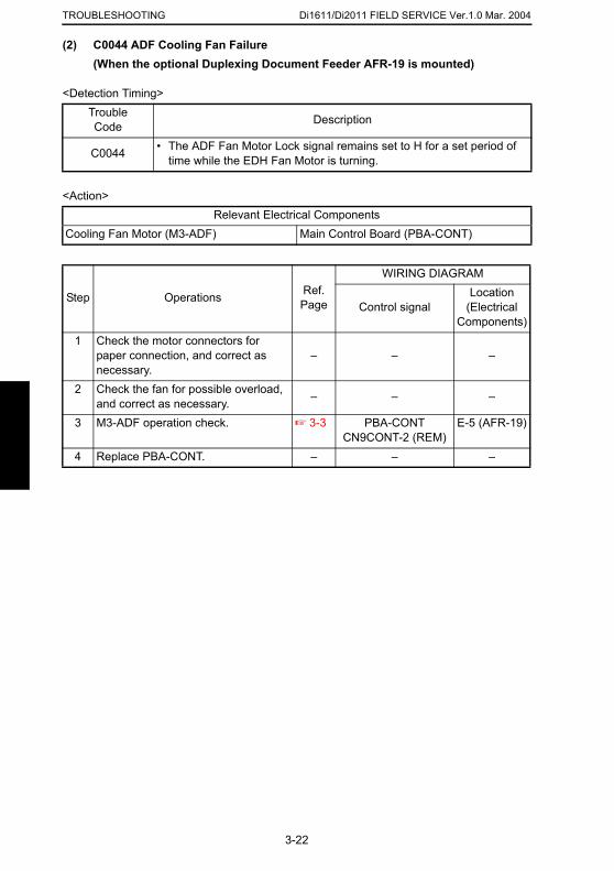
Di1611/Di2011 FIELD SERVICE Ver.1.0 Mar. 2004TROUBLESHOOTING
(2) C0044 ADF Cooling Fan Failure(When the optional Duplexing Document Feeder AFR-19 is mounted)
<Detection Timing>
<Action>
TroubleCode Description
C0044 • The ADF Fan Motor Lock signal remains set to H for a set period of time while the EDH Fan Motor is turning.
Relevant Electrical ComponentsCooling Fan Motor (M3-ADF) Main Control Board (PBA-CONT)
Step Operations Ref. Page
WIRING DIAGRAM
Control signalLocation
(Electrical Components)
1 Check the motor connectors for paper connection, and correct as necessary.
– – –
2 Check the fan for possible overload, and correct as necessary. – – –
3 M3-ADF operation check. ☞ 3-3 PBA-CONT CN9CONT-2 (REM)
E-5 (AFR-19)
4 Replace PBA-CONT. – – –
3-22
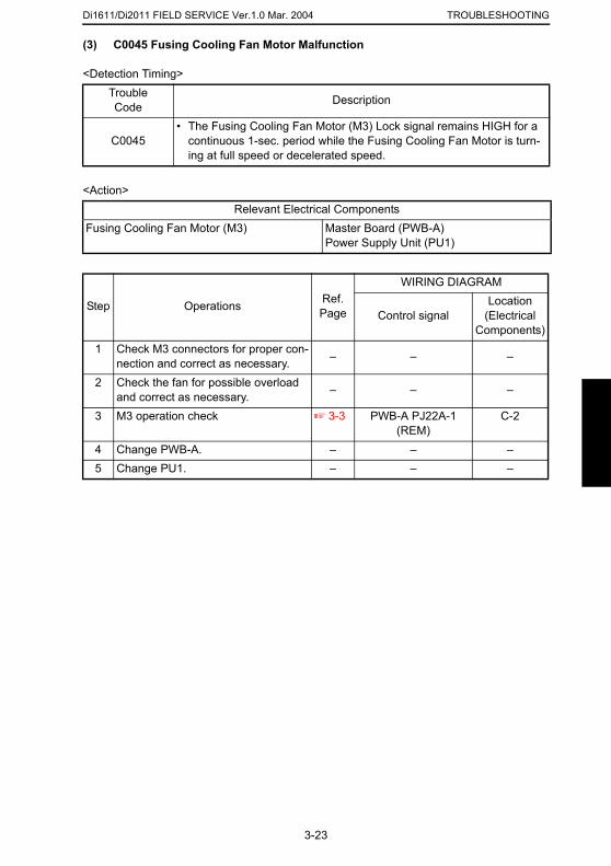
Di1611/Di2011 FIELD SERVICE Ver.1.0 Mar. 2004 TROUBLESHOOTING
(3) C0045 Fusing Cooling Fan Motor Malfunction
<Detection Timing>
<Action>
TroubleCode Description
C0045• The Fusing Cooling Fan Motor (M3) Lock signal remains HIGH for a
continuous 1-sec. period while the Fusing Cooling Fan Motor is turn-ing at full speed or decelerated speed.
Relevant Electrical ComponentsFusing Cooling Fan Motor (M3) Master Board (PWB-A)
Power Supply Unit (PU1)
Step Operations Ref. Page
WIRING DIAGRAM
Control signalLocation
(Electrical Components)
1 Check M3 connectors for proper con-nection and correct as necessary. – – –
2 Check the fan for possible overload and correct as necessary. – – –
3 M3 operation check ☞ 3-3 PWB-A PJ22A-1 (REM)
C-2
4 Change PWB-A. – – –5 Change PU1. – – –
3-23
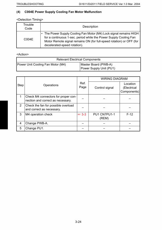
Di1611/Di2011 FIELD SERVICE Ver.1.0 Mar. 2004TROUBLESHOOTING
(4) C004E Power Supply Cooling Fan Motor Malfunction
<Detection Timing>
<Action>
TroubleCode Description
C004E
• The Power Supply Cooling Fan Motor (M4) Lock signal remains HIGH for a continuous 1-sec. period while the Power Supply Cooling Fan Motor Remote signal remains ON (for full-speed rotation) or OFF (for decelerated-speed rotation).
Relevant Electrical ComponentsPower Unit Cooling Fan Motor (M4) Master Board (PWB-A)
Power Supply Unit (PU1)
Step Operations Ref. Page
WIRING DIAGRAM
Control signalLocation
(Electrical Components)
1 Check M4 connectors for proper con-nection and correct as necessary. – – –
2 Check the fan for possible overload and correct as necessary. – – –
3 M4 operation check ☞ 3-3 PU1 CN7PU1-1 (REM)
F-12
4 Change PWB-A. – – –5 Change PU1. – – –
3-24
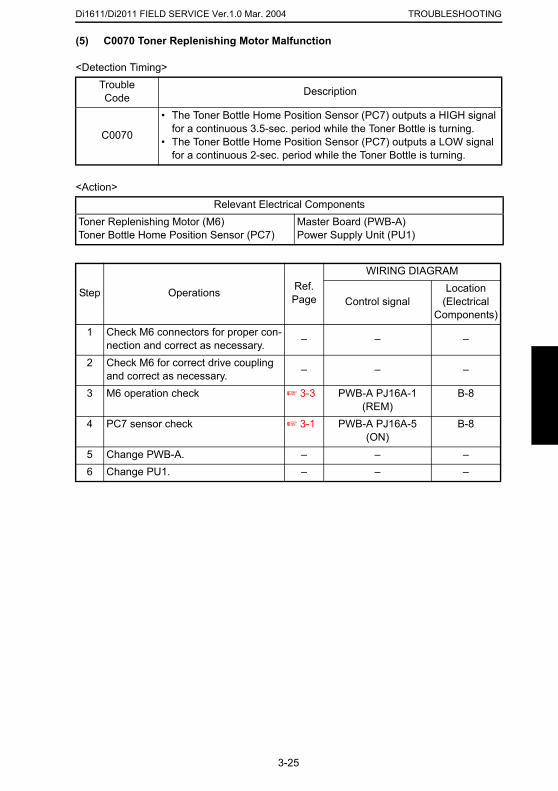
Di1611/Di2011 FIELD SERVICE Ver.1.0 Mar. 2004 TROUBLESHOOTING
(5) C0070 Toner Replenishing Motor Malfunction
<Detection Timing>
<Action>
TroubleCode Description
C0070
• The Toner Bottle Home Position Sensor (PC7) outputs a HIGH signal for a continuous 3.5-sec. period while the Toner Bottle is turning.
• The Toner Bottle Home Position Sensor (PC7) outputs a LOW signal for a continuous 2-sec. period while the Toner Bottle is turning.
Relevant Electrical ComponentsToner Replenishing Motor (M6)Toner Bottle Home Position Sensor (PC7)
Master Board (PWB-A)Power Supply Unit (PU1)
Step Operations Ref. Page
WIRING DIAGRAM
Control signalLocation
(Electrical Components)
1 Check M6 connectors for proper con-nection and correct as necessary. – – –
2 Check M6 for correct drive coupling and correct as necessary. – – –
3 M6 operation check ☞ 3-3 PWB-A PJ16A-1 (REM)
B-8
4 PC7 sensor check ☞ 3-1 PWB-A PJ16A-5 (ON)
B-8
5 Change PWB-A. – – –6 Change PU1. – – –
3-25
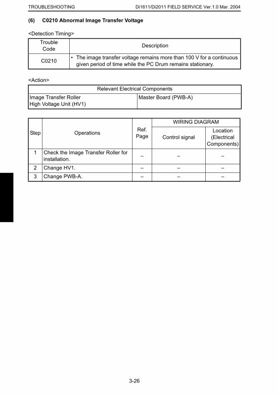
Di1611/Di2011 FIELD SERVICE Ver.1.0 Mar. 2004TROUBLESHOOTING
(6) C0210 Abnormal Image Transfer Voltage
<Detection Timing>
<Action>
TroubleCode Description
C0210 • The image transfer voltage remains more than 100 V for a continuous given period of time while the PC Drum remains stationary.
Relevant Electrical ComponentsImage Transfer RollerHigh Voltage Unit (HV1)
Master Board (PWB-A)
Step Operations Ref. Page
WIRING DIAGRAM
Control signalLocation
(Electrical Components)
1 Check the Image Transfer Roller for installation. – – –
2 Change HV1. – – –3 Change PWB-A. – – –
3-26
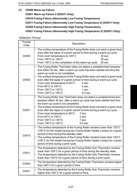
Di1611/Di2011 FIELD SERVICE Ver.1.0 Mar. 2004 TROUBLESHOOTING
(7) C0500 Warm-up Failure
C0501 Warm-up Failure 2 (Di2011 Only)C0510 Fusing Failure (Abnormally Low Fusing Temperature)C0511 Fusing Failure (Abnormally Low Fusing Temperature 2) (Di2011 Only)C0520 Fusing Failure (Abnormally High Fusing Temperature)C0521 Fusing Failure (Abnormally High Fusing Temperature 2) (Di2011 Only)<Detection Timing>TroubleCode Description
C0500
• The surface temperature of the Fusing Roller does not reach a given level even after the lapse of a given period of time during a warm-up cycle.From room temperature to 100°C: 35 sec.From 100°C to 140°C: 25 sec.From 140°C to the completion of the warm-up cycle: 20 sec.
C0500
• The Fusing Roller Thermistor does not detect a predetermined tempera-ture within 30 sec. after a warm-up cycle has been started and thus the warm-up cycle is not completed.
• The surface temperature of the Fusing Roller does not reach a given level even after the lapse of a given period of time during a warm-up cycle.From room temperature to 60°C: 4 sec.From 60°C to 100°C: 2 sec.From 100°C to 130°C: 1 sec.From 130°C to 155°C: 0.5 sec.
C0501
• The Fusing Roller Sub Thermistor does not detect a predetermined tem-perature within 30 sec. after a warm-up cycle has been started and thus the warm-up cycle is not completed.
• The surface temperature of the Fusing Roller does not reach a given level even after the lapse of a given period of time during a warm-up cycle.From room temperature to 60°C: 7 sec.From 60°C to 100°C: 2 sec.From 100°C to 130°C: 1 sec.
3-27
From 130°C to 155°C: 0.5 sec.
C0510
• The surface temperature of the Fusing Roller remains lower than 120°C (105°C for the model having two Fusing Roller Heater Lamps) for a given period of time during the standby state.
• The surface temperature of the Fusing Roller remains lower than 120°C (105°C for the model having two Fusing Roller Heater Lamps) for a given period of time during a print cycle.
C0511
• The temperature detected by the Fusing Roller Sub Thermistor remains lower than 105°C for a given period of time during the standby state.
• The temperature detected by the Fusing Roller Sub Thermistor remains lower than 105°C for a given period of time during a print cycle.
C0520 • The temperature detected by the Fusing Roller Thermistor remains higher than 240°C for a given period of time.
C0521 • The temperature detected by the Fusing Roller Sub Thermistor remains higher than 240°C for a given period of time.
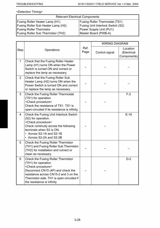
Di1611/Di2011 FIELD SERVICE Ver.1.0 Mar. 2004TROUBLESHOOTING
<Detection Timing>Relevant Electrical Components
Fusing Roller Heater Lamp (H1)Fusing Roller Sub Heater Lamp (H2)Fusing Roller ThermistorFusing Roller Sub Thermistor (TH2)
Fusing Roller Thermostat (TS1)Fusing Unit Interlock Switch (S2)Power Supply Unit (PU1)Master Board (PWB-A)
Step Operations Ref. Page
WIRING DIAGRAM
Control signalLocation
(Electrical Components)
1 Check that the Fusing Roller Heater Lamp (H1) turns ON when the Power Switch is turned ON and correct or replace the lamp as necessary.
– – –
2 Check that the Fusing Roller Sub Heater Lamp (H2) turns ON when the Power Switch is turned ON and correct or replace the lamp as necessary.
– – –
3 Check the Fusing Roller Thermostat (TS1) for operation.<Check procedure>Check the resistance of TS1. TS1 is open-circuited if its resistance is infinity.
– –
F-2
4 Check the Fusing Unit Interlock Switch (S2) for operation.<Check procedure>Check continuity across the following terminals when S2 is ON.• Across S2-1A and S2-1B• Across S2-2A and S2-2B
– –
E-16
5 Check the Fusing Roller Thermistor (TH1) and Fusing Roller Sub Thermistor
3-28
(TH2) for installation and correct or clean as necessary.
– – –
6 Check the Fusing Roller Thermistor (TH1) for operation.<Check procedure>Disconnect CN15 (4P) and check the resistance across CN15-2 and 3 on the Thermistor side. TH1 is open-circuited if the resistance is infinity.
– –
D-2
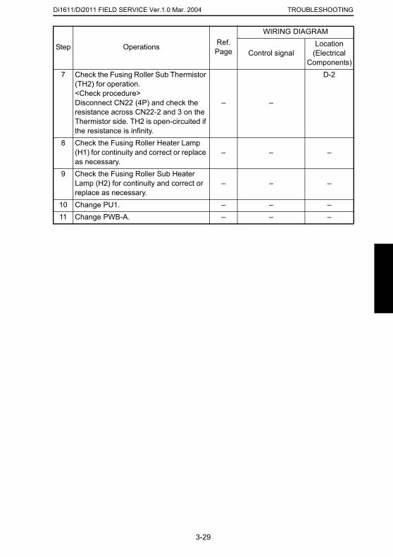
Di1611/Di2011 FIELD SERVICE Ver.1.0 Mar. 2004 TROUBLESHOOTING
7 Check the Fusing Roller Sub Thermistor (TH2) for operation.<Check procedure>Disconnect CN22 (4P) and check the resistance across CN22-2 and 3 on the Thermistor side. TH2 is open-circuited if the resistance is infinity.
– –
D-2
8 Check the Fusing Roller Heater Lamp (H1) for continuity and correct or replace as necessary.
– – –
9 Check the Fusing Roller Sub Heater Lamp (H2) for continuity and correct or replace as necessary.
– – –
10 Change PU1. – – –11 Change PWB-A. – – –
Step Operations Ref. Page
WIRING DIAGRAM
Control signalLocation
(Electrical Components)
3-29
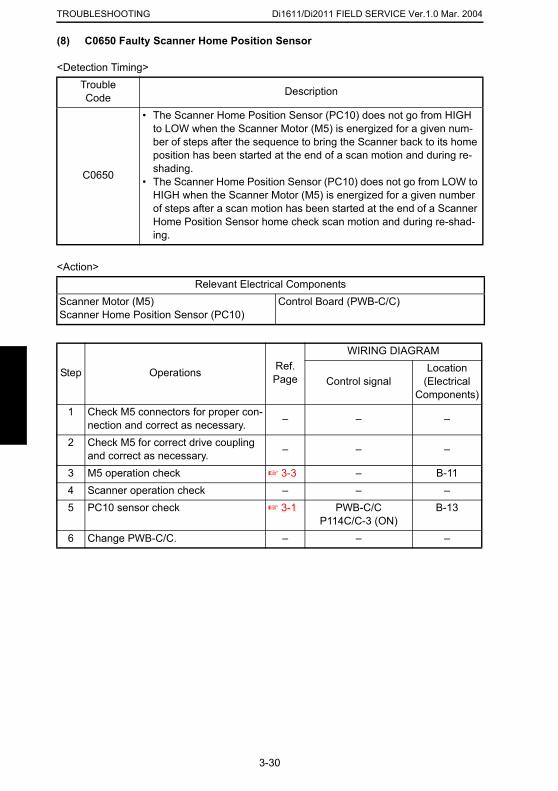
Di1611/Di2011 FIELD SERVICE Ver.1.0 Mar. 2004TROUBLESHOOTING
(8) C0650 Faulty Scanner Home Position Sensor
<Detection Timing>
<Action>
TroubleCode Description
C0650
• The Scanner Home Position Sensor (PC10) does not go from HIGH to LOW when the Scanner Motor (M5) is energized for a given num-ber of steps after the sequence to bring the Scanner back to its home position has been started at the end of a scan motion and during re-shading.
• The Scanner Home Position Sensor (PC10) does not go from LOW to HIGH when the Scanner Motor (M5) is energized for a given number of steps after a scan motion has been started at the end of a Scanner Home Position Sensor home check scan motion and during re-shad-ing.
Relevant Electrical ComponentsScanner Motor (M5)Scanner Home Position Sensor (PC10)
Control Board (PWB-C/C)
Step Operations Ref. Page
WIRING DIAGRAM
Control signalLocation
(Electrical Components)
1 Check M5 connectors for proper con-nection and correct as necessary. – – –
2 Check M5 for correct drive coupling and correct as necessary. – – –
3 M5 operation check ☞ 3-3 – B-114 Scanner operation check – – –5 PC10 sensor check ☞ 3-1 PWB-C/C B-13
3-30
P114C/C-3 (ON)6 Change PWB-C/C. – – –
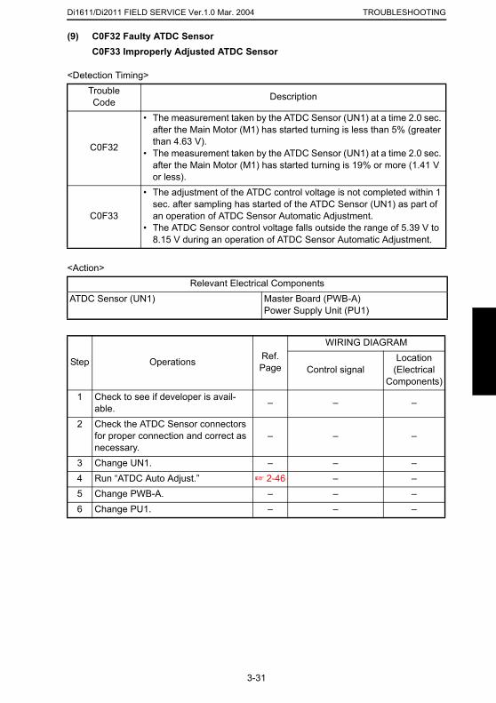
Di1611/Di2011 FIELD SERVICE Ver.1.0 Mar. 2004 TROUBLESHOOTING
(9) C0F32 Faulty ATDC Sensor
C0F33 Improperly Adjusted ATDC Sensor<Detection Timing>
<Action>
TroubleCode Description
C0F32
• The measurement taken by the ATDC Sensor (UN1) at a time 2.0 sec. after the Main Motor (M1) has started turning is less than 5% (greater than 4.63 V).
• The measurement taken by the ATDC Sensor (UN1) at a time 2.0 sec. after the Main Motor (M1) has started turning is 19% or more (1.41 V or less).
C0F33
• The adjustment of the ATDC control voltage is not completed within 1 sec. after sampling has started of the ATDC Sensor (UN1) as part of an operation of ATDC Sensor Automatic Adjustment.
• The ATDC Sensor control voltage falls outside the range of 5.39 V to 8.15 V during an operation of ATDC Sensor Automatic Adjustment.
Relevant Electrical ComponentsATDC Sensor (UN1) Master Board (PWB-A)
Power Supply Unit (PU1)
Step Operations Ref. Page
WIRING DIAGRAM
Control signalLocation
(Electrical Components)
1 Check to see if developer is avail-able. – – –
2 Check the ATDC Sensor connectors for proper connection and correct as – – –
3-31
necessary.3 Change UN1. – – –4 Run “ATDC Auto Adjust.” ☞ 2-46 – –5 Change PWB-A. – – –6 Change PU1. – – –
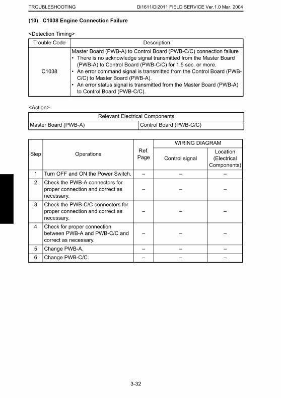
Di1611/Di2011 FIELD SERVICE Ver.1.0 Mar. 2004TROUBLESHOOTING
(10) C1038 Engine Connection Failure
<Detection Timing>
<Action>
Trouble Code Description
C1038
Master Board (PWB-A) to Control Board (PWB-C/C) connection failure• There is no acknowledge signal transmitted from the Master Board
(PWB-A) to Control Board (PWB-C/C) for 1.5 sec. or more.• An error command signal is transmitted from the Control Board (PWB-
C/C) to Master Board (PWB-A).• An error status signal is transmitted from the Master Board (PWB-A)
to Control Board (PWB-C/C).
Relevant Electrical ComponentsMaster Board (PWB-A) Control Board (PWB-C/C)
Step Operations Ref. Page
WIRING DIAGRAM
Control signalLocation
(Electrical Components)
1 Turn OFF and ON the Power Switch. – – –2 Check the PWB-A connectors for
proper connection and correct as necessary.
– – –
3 Check the PWB-C/C connectors for proper connection and correct as necessary.
– – –
4 Check for proper connection between PWB-A and PWB-C/C and correct as necessary.
– – –
5 Change PWB-A. – – –
3-32
6 Change PWB-C/C. – – –
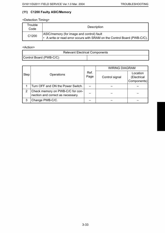
Di1611/Di2011 FIELD SERVICE Ver.1.0 Mar. 2004 TROUBLESHOOTING
(11) C1200 Faulty ASIC/Memory
<Detection Timing>
<Action>
TroubleCode Description
C1200 ASIC/memory (for image and control) fault• A write or read error occurs with SRAM on the Control Board (PWB-C/C).
Relevant Electrical ComponentsControl Board (PWB-C/C)
Step Operations Ref. Page
WIRING DIAGRAM
Control signalLocation
(Electrical Components)
1 Turn OFF and ON the Power Switch. – – –2 Check memory on PWB-C/C for con-
nection and correct as necessary. – – –
3 Change PWB-C/C. – – –
3-33
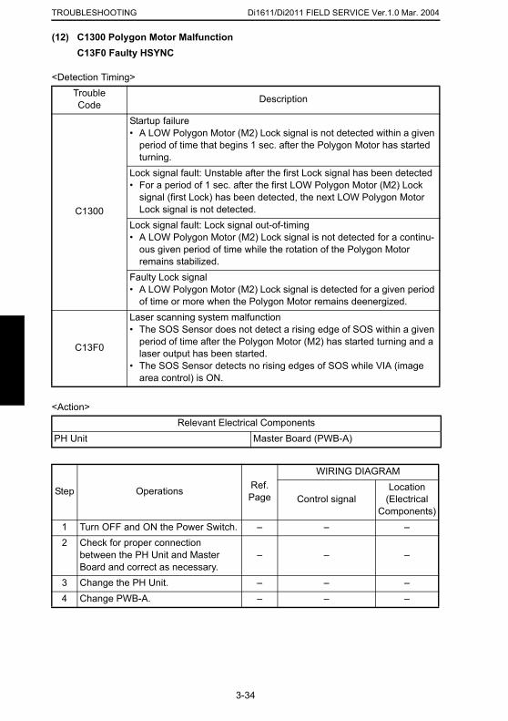
Di1611/Di2011 FIELD SERVICE Ver.1.0 Mar. 2004TROUBLESHOOTING
(12) C1300 Polygon Motor MalfunctionC13F0 Faulty HSYNC
<Detection Timing>
<Action>
TroubleCode Description
C1300
Startup failure• A LOW Polygon Motor (M2) Lock signal is not detected within a given
period of time that begins 1 sec. after the Polygon Motor has started turning.
Lock signal fault: Unstable after the first Lock signal has been detected• For a period of 1 sec. after the first LOW Polygon Motor (M2) Lock
signal (first Lock) has been detected, the next LOW Polygon Motor Lock signal is not detected.
Lock signal fault: Lock signal out-of-timing• A LOW Polygon Motor (M2) Lock signal is not detected for a continu-
ous given period of time while the rotation of the Polygon Motor remains stabilized.
Faulty Lock signal• A LOW Polygon Motor (M2) Lock signal is detected for a given period
of time or more when the Polygon Motor remains deenergized.
C13F0
Laser scanning system malfunction• The SOS Sensor does not detect a rising edge of SOS within a given
period of time after the Polygon Motor (M2) has started turning and a laser output has been started.
• The SOS Sensor detects no rising edges of SOS while VIA (image area control) is ON.
Relevant Electrical ComponentsPH Unit Master Board (PWB-A)
3-34
Step Operations Ref. Page
WIRING DIAGRAM
Control signalLocation
(Electrical Components)
1 Turn OFF and ON the Power Switch. – – –2 Check for proper connection
between the PH Unit and Master Board and correct as necessary.
– – –
3 Change the PH Unit. – – –4 Change PWB-A. – – –
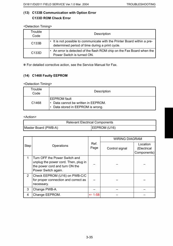
Di1611/Di2011 FIELD SERVICE Ver.1.0 Mar. 2004 TROUBLESHOOTING
(13) C133B Communication with Option Error
C133D ROM Check Error<Detection Timing>
✽ For detailed corrective action, see the Service Manual for Fax.
(14) C1468 Faulty EEPROM
<Detection Timing>
<Action>
TroubleCode Description
C133B • It is not possible to communicate with the Printer Board within a pre-determined period of time during a print cycle.
C133D • An error is detected of the flash ROM chip on the Fax Board when the Power Switch is turned ON.
TroubleCode Description
C1468EEPROM fault• Data cannot be written in EEPROM.• Data stored in EEPROM is wrong.
Relevant Electrical ComponentsMaster Board (PWB-A) EEPROM (U16)
Step Operations Ref. Page
WIRING DIAGRAM
Control signalLocation
(Electrical Components)
3-35
1 Turn OFF the Power Switch and unplug the power cord. Then, plug in the power cord and turn ON the Power Switch again.
– – –
2 Check EEPROM (U16) on PWB-C/C for proper connection and correct as necessary.
– – –
3 Change PWB-A. – – –4 Change EEPROM. ☞ 1-58 – –
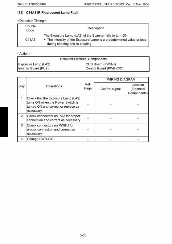
Di1611/Di2011 FIELD SERVICE Ver.1.0 Mar. 2004TROUBLESHOOTING
(15) C14A3 IR Fluorescent Lamp Fault
<Detection Timing>
<Action>
TroubleCode Description
C14A3The Exposure Lamp (LA2) of the Scanner fails to turn ON.• The intensity of the Exposure Lamp is a predetermined value or less
during shading and re-shading.
Relevant Electrical ComponentsExposure Lamp (LA2)Inverter Board (PU2)
CCD Board (PWB-J)Control Board (PWB-C/C)
Step Operations Ref. Page
WIRING DIAGRAM
Control signalLocation
(Electrical Components)
1 Check that the Exposure Lamp (LA2) turns ON when the Power Switch is turned ON and correct or replace as necessary.
– – –
2 Check connectors on PU2 for proper connection and correct as necessary. – – –
3 Check connectors on PWB-J for proper connection and correct as necessary.
– – –
4 Change PWB-C/C. – – –
3-36
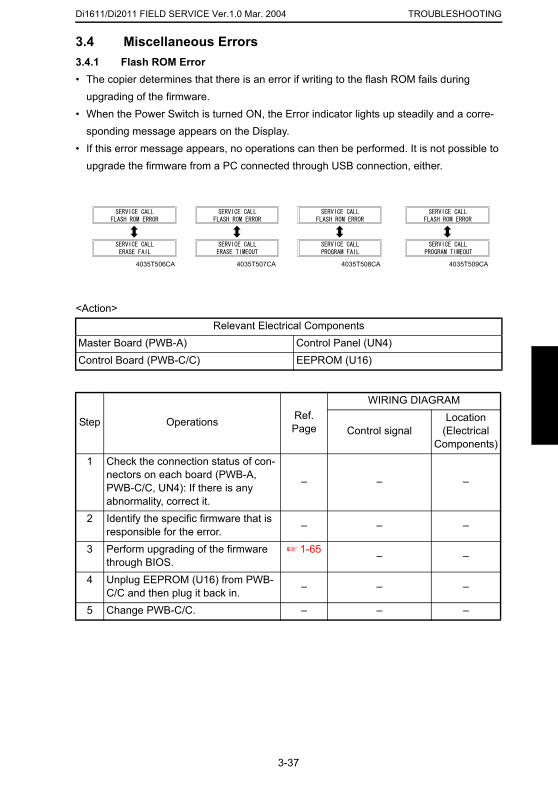
Di1611/Di2011 FIELD SERVICE Ver.1.0 Mar. 2004 TROUBLESHOOTING
3.4 Miscellaneous Errors3.4.1 Flash ROM Error• The copier determines that there is an error if writing to the flash ROM fails during
upgrading of the firmware.• When the Power Switch is turned ON, the Error indicator lights up steadily and a corre-
sponding message appears on the Display.• If this error message appears, no operations can then be performed. It is not possible to
upgrade the firmware from a PC connected through USB connection, either.
<Action>Relevant Electrical Components
Master Board (PWB-A) Control Panel (UN4)Control Board (PWB-C/C) EEPROM (U16)
Step Operations Ref. Page
WIRING DIAGRAM
Control signalLocation
(Electrical Components)
1 Check the connection status of con-nectors on each board (PWB-A, PWB-C/C, UN4): If there is any – – –
4035T506CA 4035T507CA 4035T508CA 4035T509CA
3-37
abnormality, correct it.2 Identify the specific firmware that is
responsible for the error. – – –
3 Perform upgrading of the firmware through BIOS.
☞ 1-65 – –
4 Unplug EEPROM (U16) from PWB-C/C and then plug it back in. – – –
5 Change PWB-C/C. – – –
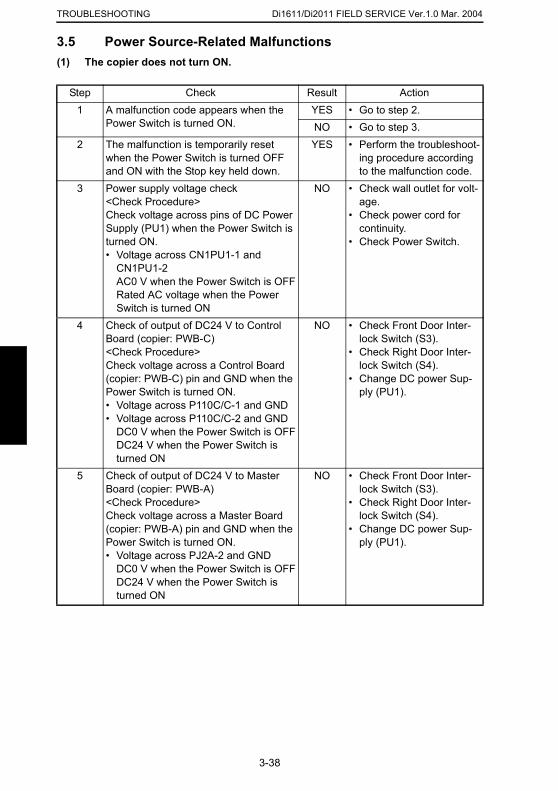
Di1611/Di2011 FIELD SERVICE Ver.1.0 Mar. 2004TROUBLESHOOTING
3.5 Power Source-Related Malfunctions
(1) The copier does not turn ON.Step Check Result Action1 A malfunction code appears when the
Power Switch is turned ON.YES • Go to step 2.NO • Go to step 3.
2 The malfunction is temporarily reset when the Power Switch is turned OFF and ON with the Stop key held down.
YES • Perform the troubleshoot-ing procedure according to the malfunction code.
3 Power supply voltage check<Check Procedure>Check voltage across pins of DC Power Supply (PU1) when the Power Switch is turned ON.• Voltage across CN1PU1-1 and
CN1PU1-2AC0 V when the Power Switch is OFFRated AC voltage when the Power Switch is turned ON
NO • Check wall outlet for volt-age.
• Check power cord for continuity.
• Check Power Switch.
4 Check of output of DC24 V to Control Board (copier: PWB-C)<Check Procedure>Check voltage across a Control Board (copier: PWB-C) pin and GND when the Power Switch is turned ON.• Voltage across P110C/C-1 and GND• Voltage across P110C/C-2 and GND
DC0 V when the Power Switch is OFFDC24 V when the Power Switch is turned ON
NO • Check Front Door Inter-lock Switch (S3).
• Check Right Door Inter-lock Switch (S4).
• Change DC power Sup-ply (PU1).
5 Check of output of DC24 V to Master Board (copier: PWB-A)<Check Procedure>
NO • Check Front Door Inter-lock Switch (S3).
• Check Right Door Inter-
3-38
Check voltage across a Master Board (copier: PWB-A) pin and GND when the Power Switch is turned ON.• Voltage across PJ2A-2 and GND
DC0 V when the Power Switch is OFFDC24 V when the Power Switch is turned ON
lock Switch (S4).• Change DC power Sup-
ply (PU1).
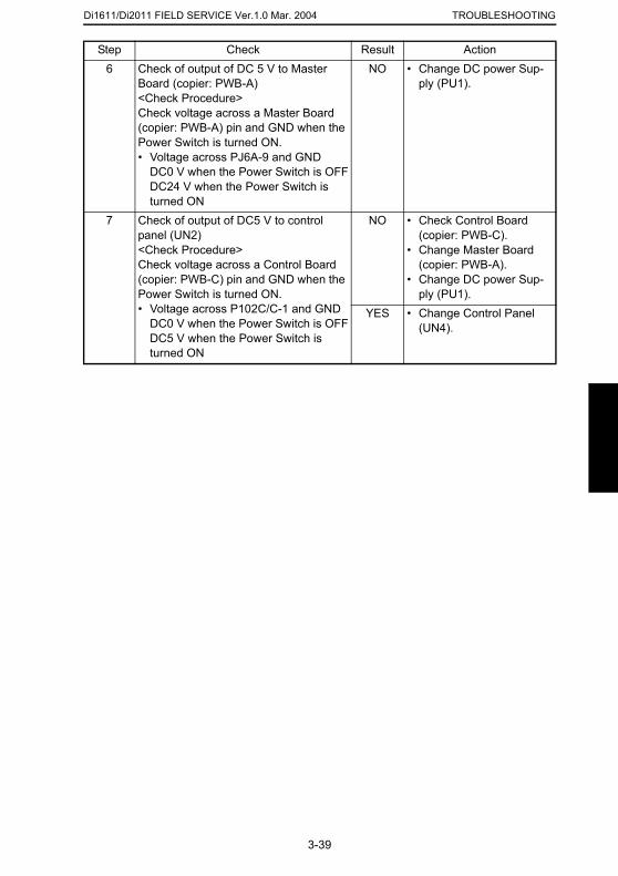
Di1611/Di2011 FIELD SERVICE Ver.1.0 Mar. 2004 TROUBLESHOOTING
6 Check of output of DC 5 V to Master Board (copier: PWB-A)<Check Procedure>Check voltage across a Master Board (copier: PWB-A) pin and GND when the Power Switch is turned ON.• Voltage across PJ6A-9 and GND
DC0 V when the Power Switch is OFFDC24 V when the Power Switch is turned ON
NO • Change DC power Sup-ply (PU1).
7 Check of output of DC5 V to control panel (UN2)<Check Procedure>Check voltage across a Control Board (copier: PWB-C) pin and GND when the Power Switch is turned ON.• Voltage across P102C/C-1 and GND
DC0 V when the Power Switch is OFFDC5 V when the Power Switch is turned ON
NO • Check Control Board (copier: PWB-C).
• Change Master Board (copier: PWB-A).
• Change DC power Sup-ply (PU1).
YES • Change Control Panel (UN4).
Step Check Result Action
3-39
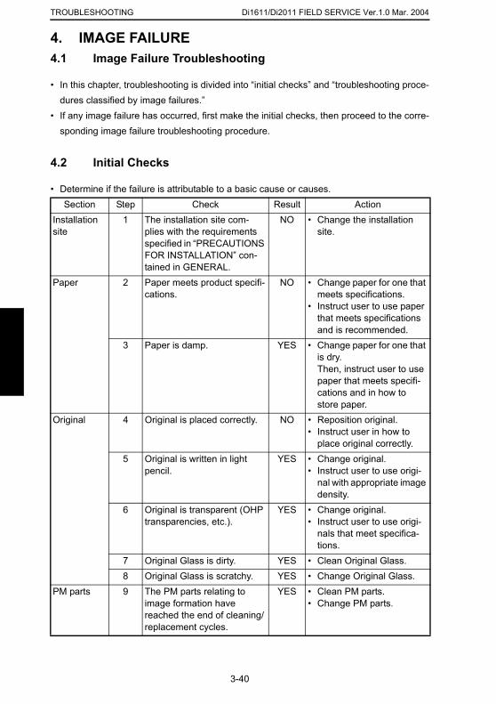
Di1611/Di2011 FIELD SERVICE Ver.1.0 Mar. 2004TROUBLESHOOTING
4. IMAGE FAILURE
4.1 Image Failure Troubleshooting• In this chapter, troubleshooting is divided into “initial checks” and “troubleshooting proce-dures classified by image failures.”
• If any image failure has occurred, first make the initial checks, then proceed to the corre-sponding image failure troubleshooting procedure.
4.2 Initial Checks
• Determine if the failure is attributable to a basic cause or causes.Section Step Check Result Action
Installation site
1 The installation site com-plies with the requirements specified in “PRECAUTIONS FOR INSTALLATION” con-tained in GENERAL.
NO • Change the installation site.
Paper 2 Paper meets product specifi-cations.
NO • Change paper for one that meets specifications.
• Instruct user to use paper that meets specifications and is recommended.
3 Paper is damp. YES • Change paper for one that is dry.Then, instruct user to use paper that meets specifi-cations and in how to store paper.
Original 4 Original is placed correctly. NO • Reposition original.• Instruct user in how to
place original correctly.
3-40
5 Original is written in light pencil.
YES • Change original.• Instruct user to use origi-
nal with appropriate image density.
6 Original is transparent (OHP transparencies, etc.).
YES • Change original.• Instruct user to use origi-
nals that meet specifica-tions.
7 Original Glass is dirty. YES • Clean Original Glass.8 Original Glass is scratchy. YES • Change Original Glass.
PM parts 9 The PM parts relating to image formation have reached the end of cleaning/replacement cycles.
YES • Clean PM parts.• Change PM parts.
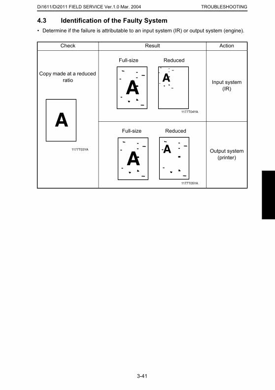
Di1611/Di2011 FIELD SERVICE Ver.1.0 Mar. 2004 TROUBLESHOOTING
4.3 Identification of the Faulty System• Determine if the failure is attributable to an input system (IR) or output system (engine).
Check Result Action
Copy made at a reduced ratio Input system
(IR)
Output system (printer)
1177T03YA
1177T04YA
Full-size Reduced
1177T05YA
Full-size Reduced
3-41
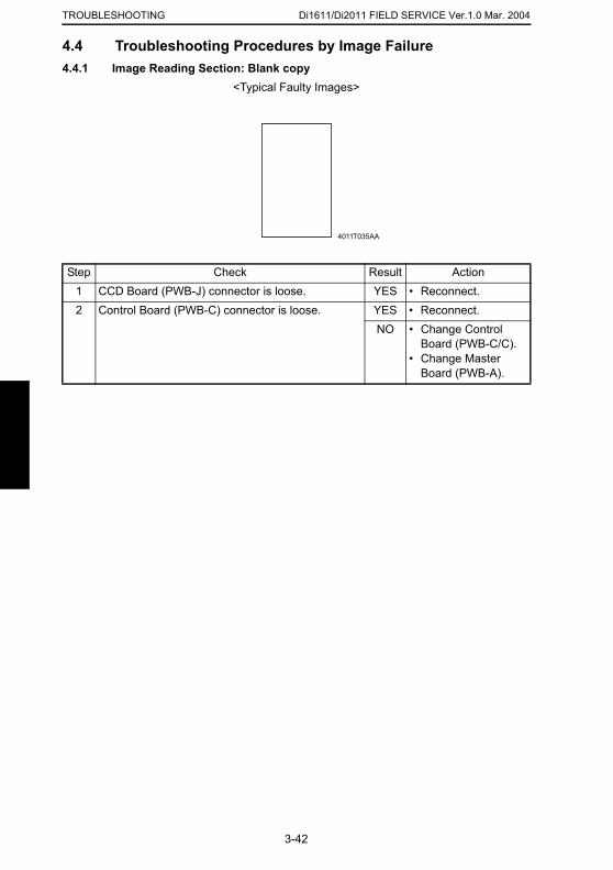
Di1611/Di2011 FIELD SERVICE Ver.1.0 Mar. 2004TROUBLESHOOTING
4.4 Troubleshooting Procedures by Image Failure
4.4.1 Image Reading Section: Blank copy<Typical Faulty Images>
Step Check Result Action1 CCD Board (PWB-J) connector is loose. YES • Reconnect.2 Control Board (PWB-C) connector is loose. YES • Reconnect.
NO • Change Control Board (PWB-C/C).
• Change Master Board (PWB-A).
4011T035AA
3-42
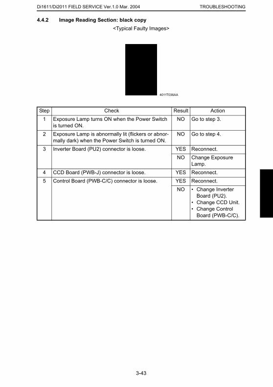
Di1611/Di2011 FIELD SERVICE Ver.1.0 Mar. 2004 TROUBLESHOOTING
4.4.2 Image Reading Section: black copy
<Typical Faulty Images>Step Check Result Action1 Exposure Lamp turns ON when the Power Switch
is turned ON.NO Go to step 3.
2 Exposure Lamp is abnormally lit (flickers or abnor-mally dark) when the Power Switch is turned ON.
NO Go to step 4.
3 Inverter Board (PU2) connector is loose. YES Reconnect.NO Change Exposure
Lamp.4 CCD Board (PWB-J) connector is loose. YES Reconnect.5 Control Board (PWB-C/C) connector is loose. YES Reconnect.
NO • Change Inverter Board (PU2).
• Change CCD Unit.• Change Control
Board (PWB-C/C).
4011T036AA
3-43
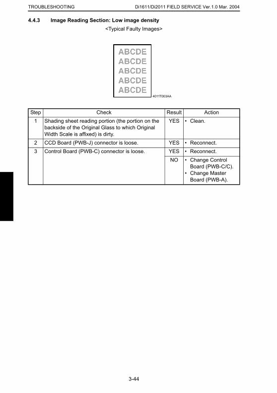
Di1611/Di2011 FIELD SERVICE Ver.1.0 Mar. 2004TROUBLESHOOTING
4.4.3 Image Reading Section: Low image density<Typical Faulty Images>
Step Check Result Action1 Shading sheet reading portion (the portion on the
backside of the Original Glass to which Original Width Scale is affixed) is dirty.
YES • Clean.
2 CCD Board (PWB-J) connector is loose. YES • Reconnect.3 Control Board (PWB-C) connector is loose. YES • Reconnect.
NO • Change Control Board (PWB-C/C).
• Change Master Board (PWB-A).
4011T003AA
3-44
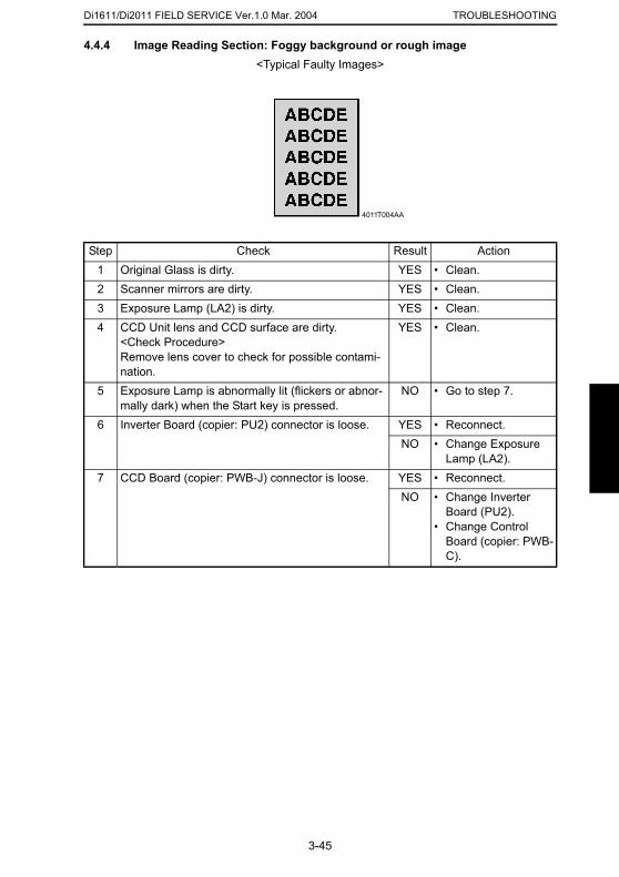
Di1611/Di2011 FIELD SERVICE Ver.1.0 Mar. 2004 TROUBLESHOOTING
4.4.4 Image Reading Section: Foggy background or rough image
<Typical Faulty Images>Step Check Result Action1 Original Glass is dirty. YES • Clean.2 Scanner mirrors are dirty. YES • Clean.3 Exposure Lamp (LA2) is dirty. YES • Clean.4 CCD Unit lens and CCD surface are dirty.
<Check Procedure>Remove lens cover to check for possible contami-nation.
YES • Clean.
5 Exposure Lamp is abnormally lit (flickers or abnor-mally dark) when the Start key is pressed.
NO • Go to step 7.
6 Inverter Board (copier: PU2) connector is loose. YES • Reconnect.NO • Change Exposure
Lamp (LA2).7 CCD Board (copier: PWB-J) connector is loose. YES • Reconnect.
NO • Change Inverter Board (PU2).
• Change Control Board (copier: PWB-
4011T004AA
3-45
C).

Di1611/Di2011 FIELD SERVICE Ver.1.0 Mar. 2004TROUBLESHOOTING
4.4.5 Image Reading Section: Black streaks or bands<Typical Faulty Images>
Step Check Result Action1 Original Glass is dirty, scratchy, worn, or damaged. YES • Clean or change.2 Shading sheet reading portion (the portion on the
backside of the Original Glass to which Original Width Scale is affixed) is dirty.
YES • Clean.
3 Scanner mirrors are dirty, scratchy, or damaged. YES • Clean or change.4 Exposure Lamp (LA2) is dirty. YES • Clean or change.5 CCD Unit lens and CCD surface are dirty or
scratchy.<Check Procedure>Remove lens cover to check for possible contami-nation.
YES • Clean or change.
6 CCD Board (PWB-J) connector is loose. YES • Reconnect.7 Control Board (PWB-C/C) connector is loose. YES • Reconnect.
NO • Change CCD Unit.• Change Control
Board (PWB-C/C).
4011T017AA 4011T023AA
3-46

Di1611/Di2011 FIELD SERVICE Ver.1.0 Mar. 2004 TROUBLESHOOTING
4.4.6 Image Reading Section: Black spots
<Typical Faulty Images>Step Check Result Action1 Original Glass is dirty or scratchy. YES • Clean.2 CCD Board (PWB-J) connector is loose. YES • Reconnect.3 Control Board (PWB-C/C) connector is loose. YES • Reconnect.
NO • Change CCD Unit.• Change Control
Board (PWB-C/C).
4011T521AA
3-47
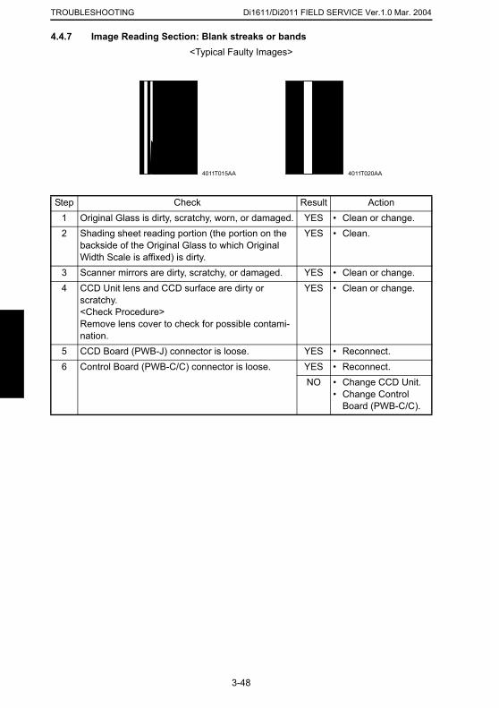
Di1611/Di2011 FIELD SERVICE Ver.1.0 Mar. 2004TROUBLESHOOTING
4.4.7 Image Reading Section: Blank streaks or bands<Typical Faulty Images>
Step Check Result Action1 Original Glass is dirty, scratchy, worn, or damaged. YES • Clean or change.2 Shading sheet reading portion (the portion on the
backside of the Original Glass to which Original Width Scale is affixed) is dirty.
YES • Clean.
3 Scanner mirrors are dirty, scratchy, or damaged. YES • Clean or change.4 CCD Unit lens and CCD surface are dirty or
scratchy.<Check Procedure>Remove lens cover to check for possible contami-nation.
YES • Clean or change.
5 CCD Board (PWB-J) connector is loose. YES • Reconnect.6 Control Board (PWB-C/C) connector is loose. YES • Reconnect.
NO • Change CCD Unit.• Change Control
Board (PWB-C/C).
4011T015AA 4011T020AA
3-48
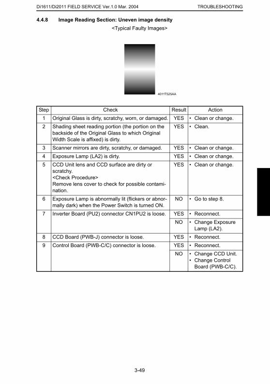
Di1611/Di2011 FIELD SERVICE Ver.1.0 Mar. 2004 TROUBLESHOOTING
4.4.8 Image Reading Section: Uneven image density
<Typical Faulty Images>Step Check Result Action1 Original Glass is dirty, scratchy, worn, or damaged. YES • Clean or change.2 Shading sheet reading portion (the portion on the
backside of the Original Glass to which Original Width Scale is affixed) is dirty.
YES • Clean.
3 Scanner mirrors are dirty, scratchy, or damaged. YES • Clean or change.4 Exposure Lamp (LA2) is dirty. YES • Clean or change.5 CCD Unit lens and CCD surface are dirty or
scratchy.<Check Procedure>Remove lens cover to check for possible contami-nation.
YES • Clean or change.
6 Exposure Lamp is abnormally lit (flickers or abnor-mally dark) when the Power Switch is turned ON.
NO • Go to step 8.
7 Inverter Board (PU2) connector CN1PU2 is loose. YES • Reconnect.NO • Change Exposure
Lamp (LA2).8 CCD Board (PWB-J) connector is loose. YES • Reconnect.
4011T525AA
3-49
9 Control Board (PWB-C/C) connector is loose. YES • Reconnect.NO • Change CCD Unit.
• Change Control Board (PWB-C/C).
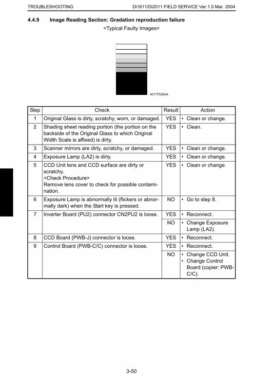
Di1611/Di2011 FIELD SERVICE Ver.1.0 Mar. 2004TROUBLESHOOTING
4.4.9 Image Reading Section: Gradation reproduction failure<Typical Faulty Images>
Step Check Result Action1 Original Glass is dirty, scratchy, worn, or damaged. YES • Clean or change.2 Shading sheet reading portion (the portion on the
backside of the Original Glass to which Original Width Scale is affixed) is dirty.
YES • Clean.
3 Scanner mirrors are dirty, scratchy, or damaged. YES • Clean or change.4 Exposure Lamp (LA2) is dirty. YES • Clean or change.5 CCD Unit lens and CCD surface are dirty or
scratchy.<Check Procedure>Remove lens cover to check for possible contami-nation.
YES • Clean or change.
6 Exposure Lamp is abnormally lit (flickers or abnor-mally dark) when the Start key is pressed.
NO • Go to step 8.
7 Inverter Board (PU2) connector CN2PU2 is loose. YES • Reconnect.NO • Change Exposure
Lamp (LA2).8 CCD Board (PWB-J) connector is loose. YES • Reconnect.9 Control Board (PWB-C/C) connector is loose. YES • Reconnect.
4011T526AA
3-50
NO • Change CCD Unit.• Change Control
Board (copier: PWB-C/C).
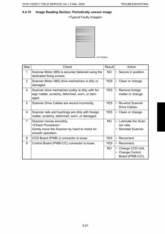
Di1611/Di2011 FIELD SERVICE Ver.1.0 Mar. 2004 TROUBLESHOOTING
4.4.10 Image Reading Section: Periodically uneven image
<Typical Faulty Images>Step Check Result Action1 Scanner Motor (M5) is securely fastened using the
dedicated fixing screws.NO • Secure in position.
2 Scanner Motor (M5) drive mechanism is dirty or damaged.
YES • Clean or change.
4 Scanner drive mechanism pulley is dirty with for-eign matter, scratchy, deformed, worn, or dam-aged.
YES • Remove foreign matter or change.
5 Scanner Drive Cables are wound incorrectly. YES • Re-wind Scanner Drive Cables.
6 Scanner rails and bushings are dirty with foreign matter, scratchy, deformed, worn, or damaged.
YES • Clean or change.
7 Scanner moves smoothly.<Check Procedure>Gently move the Scanner by hand to check for smooth operation.
NO • Lubricate the Scan-ner rails.
• Reinstall Scanner.
8 CCD Board (PWB-J) connector is loose. YES • Reconnect.9 Control Board (PWB-C/C) connector is loose. YES • Reconnect.
4011T528AA
3-51
NO • Change CCD Unit.• Change Control
Board (PWB-C/C).
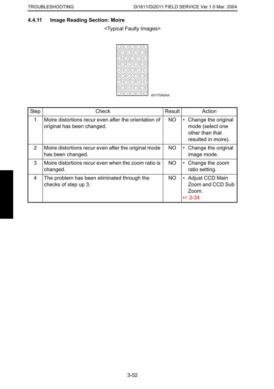
Di1611/Di2011 FIELD SERVICE Ver.1.0 Mar. 2004TROUBLESHOOTING
4.4.11 Image Reading Section: Moire<Typical Faulty Images>
Step Check Result Action1 Moire distortions recur even after the orientation of
original has been changed.NO • Change the original
mode (select one other than that resulted in moire).
2 Moire distortions recur even after the original mode has been changed.
NO • Change the original image mode.
3 Moire distortions recur even when the zoom ratio is changed.
NO • Change the zoom ratio setting.
4 The problem has been eliminated through the checks of step up 3.
NO • Adjust CCD Main Zoom and CCD Sub Zoom.
☞ 2-34
4011T040AA
3-52
Di1611/Di2011 FIELD SERVICE Ver.1.0 Mar. 2004 TROUBLESHOOTING
4.4.12 Printer Section: Blank copy
<Typical Faulty Images>Step Check Result Action1 Imaging Unit is installed correctly. NO • Reinstall.2 Connector between the Imaging Unit and copier is
dirty.YES • Clean.
3 PH Shutter (located along the laser path between the PH Unit and PC Drum) is not in correct position or malfunctions.
YES • Correct or reinstall.
4 Connectors PJ12A and PJ13A in PH unit come off or lift.
YES • Reconnect.
5 Image Transfer Roller Assy is installed correctly. NO • Reinstall.6 Image transfer current contact is dirty, broken, or
bent.YES • Clean, correct, or
change.7 Developing bias contact is dirty, broken, or bent. YES • Clean, correct, or
change.8 High Voltage Unit (HV1) connectors is loose. YES • Reconnect.9 The following voltage is supplied from the Master
Board (PWB-A).<Check procedure>
YES • Change IU.• Change PH Unit.• Change High Volt-
4011T035AA
3-53
Check that there is 24 V developing across the Master Board pin and GND when the Power Switch is turned ON (during a copy cycle or a standby state).
age Unit (HV1).NO • Change Master
Board (PWB-A).
Di1611/Di2011 FIELD SERVICE Ver.1.0 Mar. 2004TROUBLESHOOTING
4.4.13 Printer Section: Black copy<Typical Faulty Images>
Step Check Result Action1 PC Drum Charge Corona grid mesh and Comb
Electrode are loose.YES • Reinstall.
2 PC Drum Charge Corona contact is dirty, scratchy, folded, bent, or damaged.
YES • Correct or change.
3 Grid bias contact is dirty, folded, or bent. YES • Clean, correct, or change.
4 PC Drum ground contact is dirty, scratchy, bent, or damaged.
YES • Clean, correct, or change.
5 High Voltage Unit (HV1) connectors is loose. YES • Reconnect.6 The PH Unit cable is loose. YES • Reconnect.7 The following voltage is supplied from the Master
Board (PWB-A).<Check procedure>Check that there is 24 V developing across the Master Board pin and GND when the Power Switch is turned ON (during a copy cycle or a standby state).
YES • Change IU.• Change PH Unit.• Change High Volt-
age Unit (HV1).NO • Change Master
Board (copier: PWB-A).
4011T036AA
3-54
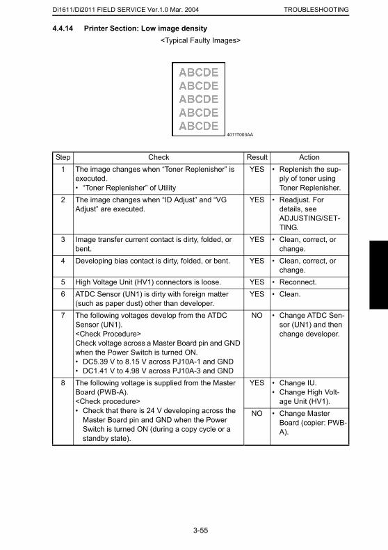
Di1611/Di2011 FIELD SERVICE Ver.1.0 Mar. 2004 TROUBLESHOOTING
4.4.14 Printer Section: Low image density
<Typical Faulty Images>Step Check Result Action1 The image changes when “Toner Replenisher” is
executed.• “Toner Replenisher” of Utility
YES • Replenish the sup-ply of toner using Toner Replenisher.
2 The image changes when “ID Adjust” and “VG Adjust” are executed.
YES • Readjust. For details, see ADJUSTING/SET-TING.
3 Image transfer current contact is dirty, folded, or bent.
YES • Clean, correct, or change.
4 Developing bias contact is dirty, folded, or bent. YES • Clean, correct, or change.
5 High Voltage Unit (HV1) connectors is loose. YES • Reconnect.6 ATDC Sensor (UN1) is dirty with foreign matter
(such as paper dust) other than developer.YES • Clean.
7 The following voltages develop from the ATDC Sensor (UN1).<Check Procedure>
NO • Change ATDC Sen-sor (UN1) and then change developer.
4011T003AA
3-55
Check voltage across a Master Board pin and GND when the Power Switch is turned ON.• DC5.39 V to 8.15 V across PJ10A-1 and GND• DC1.41 V to 4.98 V across PJ10A-3 and GND
8 The following voltage is supplied from the Master Board (PWB-A).<Check procedure>• Check that there is 24 V developing across the
Master Board pin and GND when the Power Switch is turned ON (during a copy cycle or a standby state).
YES • Change IU.• Change High Volt-
age Unit (HV1).NO • Change Master
Board (copier: PWB-A).
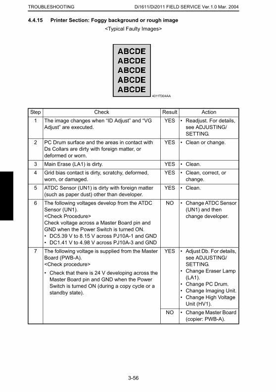
Di1611/Di2011 FIELD SERVICE Ver.1.0 Mar. 2004TROUBLESHOOTING
4.4.15 Printer Section: Foggy background or rough image<Typical Faulty Images>
Step Check Result Action1 The image changes when “ID Adjust” and “VG
Adjust” are executed.YES • Readjust. For details,
see ADJUSTING/SETTING.
2 PC Drum surface and the areas in contact with Ds Collars are dirty with foreign matter, or deformed or worn.
YES • Clean or change.
3 Main Erase (LA1) is dirty. YES • Clean.4 Grid bias contact is dirty, scratchy, deformed,
worn, or damaged.YES • Clean, correct, or
change.5 ATDC Sensor (UN1) is dirty with foreign matter
(such as paper dust) other than developer.YES • Clean.
6 The following voltages develop from the ATDC Sensor (UN1).<Check Procedure>Check voltage across a Master Board pin and GND when the Power Switch is turned ON.• DC5.39 V to 8.15 V across PJ10A-1 and GND• DC1.41 V to 4.98 V across PJ10A-3 and GND
NO • Change ATDC Sensor (UN1) and then change developer.
7 The following voltage is supplied from the Master YES • Adjust Db. For details,
4011T004AA
3-56
Board (PWB-A).<Check procedure>• Check that there is 24 V developing across the
Master Board pin and GND when the Power Switch is turned ON (during a copy cycle or a standby state).
see ADJUSTING/SETTING.
• Change Eraser Lamp (LA1).
• Change PC Drum.• Change Imaging Unit.• Change High Voltage
Unit (HV1).NO • Change Master Board
(copier: PWB-A).
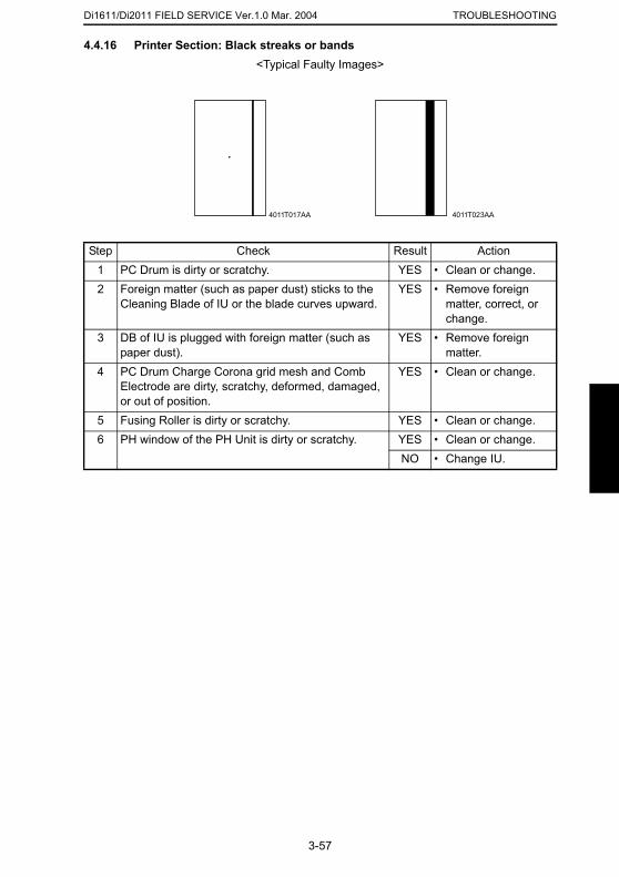
Di1611/Di2011 FIELD SERVICE Ver.1.0 Mar. 2004 TROUBLESHOOTING
4.4.16 Printer Section: Black streaks or bands
<Typical Faulty Images>Step Check Result Action1 PC Drum is dirty or scratchy. YES • Clean or change.2 Foreign matter (such as paper dust) sticks to the
Cleaning Blade of IU or the blade curves upward.YES • Remove foreign
matter, correct, or change.
3 DB of IU is plugged with foreign matter (such as paper dust).
YES • Remove foreign matter.
4 PC Drum Charge Corona grid mesh and Comb Electrode are dirty, scratchy, deformed, damaged, or out of position.
YES • Clean or change.
5 Fusing Roller is dirty or scratchy. YES • Clean or change.6 PH window of the PH Unit is dirty or scratchy. YES • Clean or change.
NO • Change IU.
4011T017AA 4011T023AA
3-57
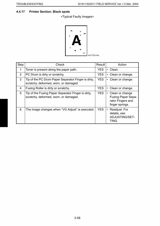
Di1611/Di2011 FIELD SERVICE Ver.1.0 Mar. 2004TROUBLESHOOTING
4.4.17 Printer Section: Black spots<Typical Faulty Images>
Step Check Result Action1 Toner is present along the paper path. YES • Clean.2 PC Drum is dirty or scratchy. YES • Clean or change.3 Tip of the PC Drum Paper Separator Finger is dirty,
scratchy, deformed, worn, or damaged.YES • Clean or change.
4 Fusing Roller is dirty or scratchy. YES • Clean or change.5 Tip of the Fusing Paper Separator Finger is dirty,
scratchy, deformed, worn, or damaged.YES • Clean or change
Fusing Paper Sepa-rator Fingers and finger springs.
6 The image changes when “VG Adjust” is executed. YES • Readjust. For details, see ADJUSTING/SET-TING.
4011T521AA
3-58
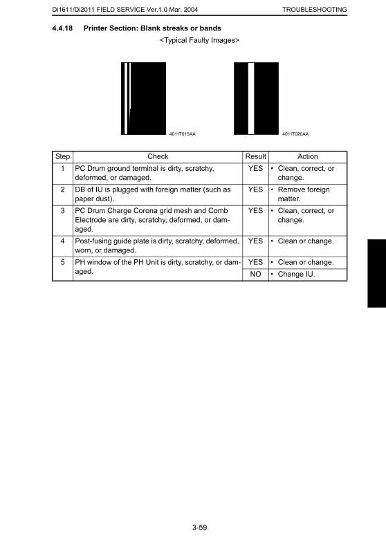
Di1611/Di2011 FIELD SERVICE Ver.1.0 Mar. 2004 TROUBLESHOOTING
4.4.18 Printer Section: Blank streaks or bands
<Typical Faulty Images>Step Check Result Action1 PC Drum ground terminal is dirty, scratchy,
deformed, or damaged.YES • Clean, correct, or
change.2 DB of IU is plugged with foreign matter (such as
paper dust).YES • Remove foreign
matter.3 PC Drum Charge Corona grid mesh and Comb
Electrode are dirty, scratchy, deformed, or dam-aged.
YES • Clean, correct, or change.
4 Post-fusing guide plate is dirty, scratchy, deformed, worn, or damaged.
YES • Clean or change.
5 PH window of the PH Unit is dirty, scratchy, or dam-aged.
YES • Clean or change.NO • Change IU.
4011T015AA 4011T020AA
3-59
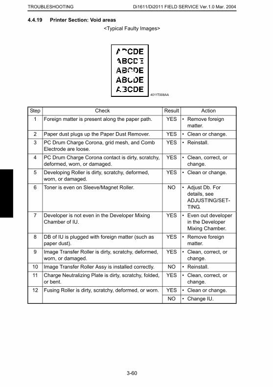
Di1611/Di2011 FIELD SERVICE Ver.1.0 Mar. 2004TROUBLESHOOTING
4.4.19 Printer Section: Void areas<Typical Faulty Images>
Step Check Result Action1 Foreign matter is present along the paper path. YES • Remove foreign
matter.2 Paper dust plugs up the Paper Dust Remover. YES • Clean or change.3 PC Drum Charge Corona, grid mesh, and Comb
Electrode are loose.YES • Reinstall.
4 PC Drum Charge Corona contact is dirty, scratchy, deformed, worn, or damaged.
YES • Clean, correct, or change.
5 Developing Roller is dirty, scratchy, deformed, worn, or damaged.
YES • Clean or change.
6 Toner is even on Sleeve/Magnet Roller. NO • Adjust Db. For details, see ADJUSTING/SET-TING.
7 Developer is not even in the Developer Mixing Chamber of IU.
YES • Even out developer in the Developer Mixing Chamber.
8 DB of IU is plugged with foreign matter (such as paper dust).
YES • Remove foreign matter.
4011T008AA
3-60
9 Image Transfer Roller is dirty, scratchy, deformed, worn, or damaged.
YES • Clean, correct, or change.
10 Image Transfer Roller Assy is installed correctly. NO • Reinstall.11 Charge Neutralizing Plate is dirty, scratchy, folded,
or bent.YES • Clean, correct, or
change.12 Fusing Roller is dirty, scratchy, deformed, or worn. YES • Clean or change.
NO • Change IU.
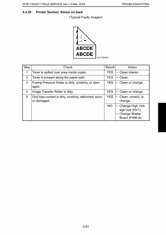
Di1611/Di2011 FIELD SERVICE Ver.1.0 Mar. 2004 TROUBLESHOOTING
4.4.20 Printer Section: Smear on back
<Typical Faulty Images>Step Check Result Action1 Toner is spilled over area inside copier. YES • Clean interior.2 Toner is present along the paper path. YES • Clean.3 Fusing Pressure Roller is dirty, scratchy, or dam-
aged.YES • Clean or change.
4 Image Transfer Roller is dirty. YES • Clean or change.5 Grid bias contact is dirty, scratchy, deformed, worn,
or damaged.YES • Clean, correct, or
change.NO • Change High Volt-
age Unit (HV1).• Change Master
Board (PWB-A).
4011T009AA
3-61
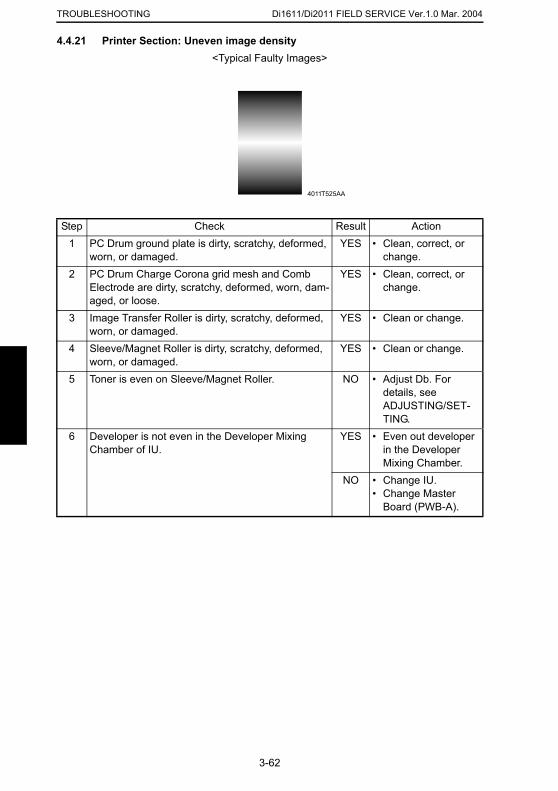
Di1611/Di2011 FIELD SERVICE Ver.1.0 Mar. 2004TROUBLESHOOTING
4.4.21 Printer Section: Uneven image density<Typical Faulty Images>
Step Check Result Action1 PC Drum ground plate is dirty, scratchy, deformed,
worn, or damaged.YES • Clean, correct, or
change.2 PC Drum Charge Corona grid mesh and Comb
Electrode are dirty, scratchy, deformed, worn, dam-aged, or loose.
YES • Clean, correct, or change.
3 Image Transfer Roller is dirty, scratchy, deformed, worn, or damaged.
YES • Clean or change.
4 Sleeve/Magnet Roller is dirty, scratchy, deformed, worn, or damaged.
YES • Clean or change.
5 Toner is even on Sleeve/Magnet Roller. NO • Adjust Db. For details, see ADJUSTING/SET-TING.
6 Developer is not even in the Developer Mixing Chamber of IU.
YES • Even out developer in the Developer Mixing Chamber.
NO • Change IU.• Change Master
Board (PWB-A).
4011T525AA
3-62
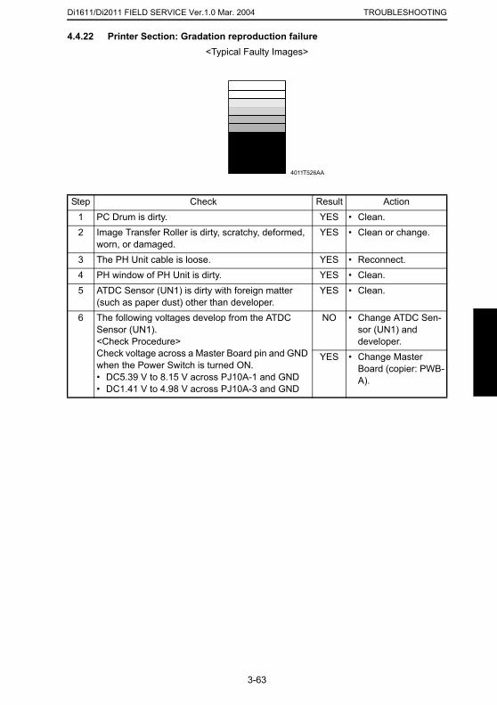
Di1611/Di2011 FIELD SERVICE Ver.1.0 Mar. 2004 TROUBLESHOOTING
4.4.22 Printer Section: Gradation reproduction failure
<Typical Faulty Images>Step Check Result Action1 PC Drum is dirty. YES • Clean.2 Image Transfer Roller is dirty, scratchy, deformed,
worn, or damaged.YES • Clean or change.
3 The PH Unit cable is loose. YES • Reconnect.4 PH window of PH Unit is dirty. YES • Clean.5 ATDC Sensor (UN1) is dirty with foreign matter
(such as paper dust) other than developer.YES • Clean.
6 The following voltages develop from the ATDC Sensor (UN1).<Check Procedure>Check voltage across a Master Board pin and GND when the Power Switch is turned ON.• DC5.39 V to 8.15 V across PJ10A-1 and GND• DC1.41 V to 4.98 V across PJ10A-3 and GND
NO • Change ATDC Sen-sor (UN1) and developer.
YES • Change Master Board (copier: PWB-A).
4011T526AA
3-63
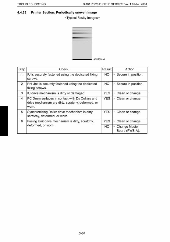
Di1611/Di2011 FIELD SERVICE Ver.1.0 Mar. 2004TROUBLESHOOTING
4.4.23 Printer Section: Periodically uneven image<Typical Faulty Images>
Step Check Result Action1 IU is securely fastened using the dedicated fixing
screws.NO • Secure in position.
2 PH Unit is securely fastened using the dedicated fixing screws.
NO • Secure in position.
3 IU drive mechanism is dirty or damaged. YES • Clean or change.4 PC Drum surfaces in contact with Ds Collars and
drive mechanism are dirty, scratchy, deformed, or worn.
YES • Clean or change.
5 Synchronizing Roller drive mechanism is dirty, scratchy, deformed, or worn.
YES • Clean or change.
6 Fusing Unit drive mechanism is dirty, scratchy, deformed, or worn.
YES • Clean or change.NO • Change Master
Board (PWB-A).
4011T528AA
3-64

SERVICE MANUAL
2004.3Ver. 1.0
FIELD SERVICE
AF-12

INDEX
ADJUSTMENT/SETTING
MAINTENANCE
TROUBLESHOOTING
CONTENTS
MAINTENANCE1. MAINTENANCE SCHEDULE .......................................................................... 1-1
1.1 PM Parts List ............................................................................................ 1-11.2 Replacement and Cleaning of Parts ........................................................ 1-2
(1) Cleaning of the Pick-up Roller/Take-up Roller ....................... 1-2(2) Removal of the Pick-Up Roller/Take-Up Roller ...................... 1-2(3) Removal of the Separator Roller ............................................ 1-3(4) Cleaning of the Separator Roller ............................................ 1-4(5) Cleaning of the Registration Roller/Rolls ............................... 1-4(6) Cleaning of the Exit Roller/Rolls ............................................ 1-5(7) Cleaning of the Transport Rolls ............................................. 1-6(8) Cleaning of Length Size Sensor 2 ......................................... 1-6
2. MISCELLANEOUS PARTS .............................................................................. 1-72.1 Disassembly and Reassembly ................................................................. 1-7
2.1.1 Identification and Removal Procedures of Door, Covers, and Exterior Parts 1-7
2.1.2 Removal of Circuit Boards and Other Electric Components .......... 1-8(1) Removal of the Interface Board (PWB/AF) ............................ 1-8
ADJUSTING/SETTING1. SERVICE MODE .............................................................................................. 2-1
1.1 Service Mode Function Setting Procedure ............................................... 2-11.2 Setting in the Service Mode ..................................................................... 2-2
1.2.1 ADJUST ......................................................................................... 2-2(1) ADF SUB ZOOM .................................................................... 2-2(2) ADF MAIN REGIST ............................................................... 2-3(3) ADF SUB REGIST1 ............................................................... 2-4
1.2.2 FUNCTION .................................................................................... 2-5(1) ADF FEED TEST ................................................................... 2-5(2) COPY ADF GLASS AREA ..................................................... 2-5
2. MECHANICAL ADJUSTMENTS ...................................................................... 2-62.1 ADF Height Adjustment ............................................................................ 2-62.2 ADF Leading Edge Skew Adjustment ...................................................... 2-7
TROUBLESHOOTING3. INTRODUCTION .............................................................................................. 3-1
3.1 Electrical Components Check Procedure ................................................ 3-13.1.1 Sensor ........................................................................................... 3-13.1.2 Switch ............................................................................................ 3-23.1.3 Solenoid ......................................................................................... 3-23.1.4 Clutch ............................................................................................ 3-23.1.5 Motor ............................................................................................. 3-3
4. MISFEEDS ....................................................................................................... 3-44.1 Initial Checks ............................................................................................ 3-44.2 Paper Misfeed Detection .......................................................................... 3-4
4.2.1 Outline ........................................................................................... 3-44.3 Misfeed Display ........................................................................................ 3-54.4 Misfeed-Detecting Sensor Layout ............................................................ 3-6
i

4.5 Misfeed Detection Timing/Troubleshooting Procedures .......................... 3-74.5.1 Misfeed at the Document Take-up Section ................................... 3-74.5.2 Misfeed at the Document Transport Section ................................. 3-84.5.3 Misfeed at the Document Exit Section ........................................... 3-9
ii

MAINTENANCE
19971
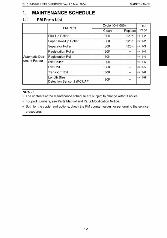
Di1611/Di2011 FIELD SERVICE Ver.1.0 Mar. 2004 MAINTENANCE
1. MAINTENANCE SCHEDULE1.1 PM Parts List
NOTES• The contents of the maintenance schedule are subject to change without notice.
• For part numbers, see Parts Manual and Parts Modification Notice.
• Both for the copier and options, check the PM counter values for performing the service
procedures.
PM PartsCycle (K=1,000) Ref.
PageClean Replace
Automatic Doc-ument Feeder
Pick-Up Roller 30K 120K ☞ 1-2
Paper Take-Up Roller 30K 120K ☞ 1-2
Separator Roller 30K 120K ☞ 1-3
Registration Roller 30K – ☞ 1-4
Registration Roll 30K – ☞ 1-4
Exit Roller 30K – ☞ 1-5
Exit Roll 30K – ☞ 1-5
Transport Roll 30K – ☞ 1-6
Length SizeDetection Sensor 2 (PC7/AF)
30K –☞ 1-6
1-1

Di1611/Di2011 FIELD SERVICE Ver.1.0 Mar. 2004MAINTENANCE
1.2 Replacement and Cleaning of Parts(1) Cleaning of the Pick-up Roller/Take-up Roller
1. Open the Upper Door.
(2) Removal of the Pick-Up Roller/Take-Up Roller
1. Open the Upper Door.
2. Open the Document Take-up Section Cover.
☞ 1-7
2. Using a soft cloth dampened with alcohol, wipe
the Take-up Roller clean of dirt.
4688D017AB
3. Using a soft cloth dampened with alcohol, wipe
the Pick-up Roller clean of dirt.
4688D018AB
3. Snap off two C-clips.
4. Remove two bushings and the Pick-up Roller/
Take-up Roller Assy.
4688D019AA
1-2
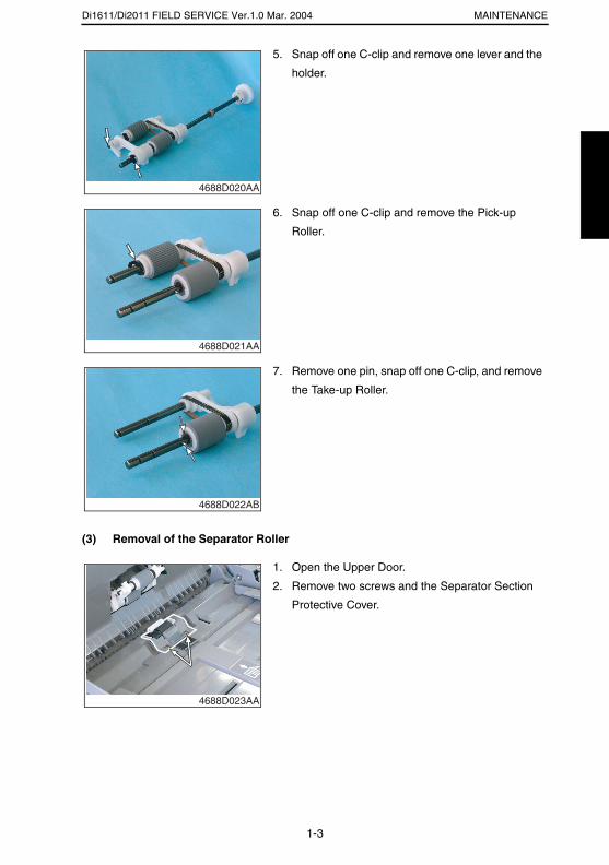
Di1611/Di2011 FIELD SERVICE Ver.1.0 Mar. 2004 MAINTENANCE
(3) Removal of the Separator Roller
5. Snap off one C-clip and remove one lever and the
holder.
4688D020AA
6. Snap off one C-clip and remove the Pick-up
Roller.
4688D021AA
7. Remove one pin, snap off one C-clip, and remove
the Take-up Roller.
4688D022AB
1. Open the Upper Door.
2. Remove two screws and the Separator Section
Protective Cover.
4688D023AA
1-3
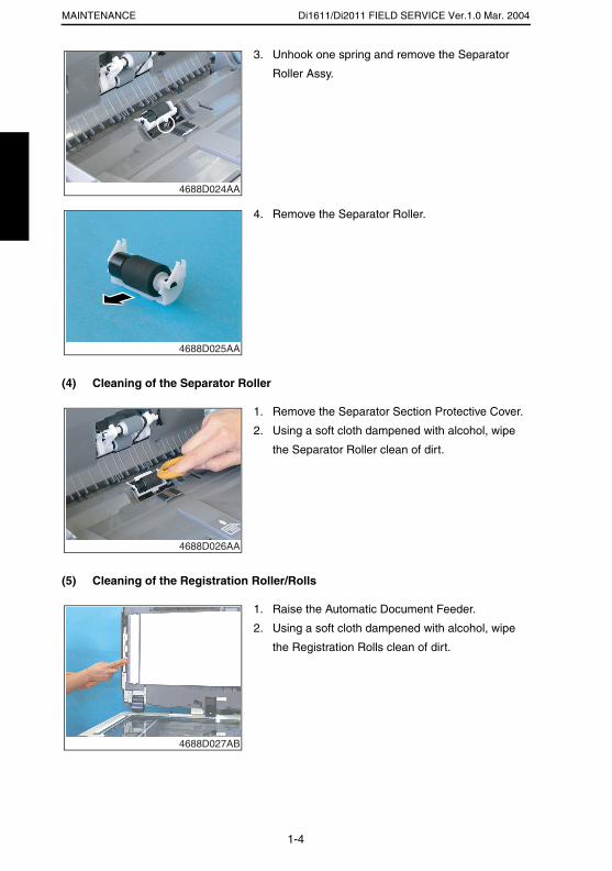
Di1611/Di2011 FIELD SERVICE Ver.1.0 Mar. 2004MAINTENANCE
(4) Cleaning of the Separator Roller
(5) Cleaning of the Registration Roller/Rolls
3. Unhook one spring and remove the Separator
Roller Assy.
4688D024AA
4. Remove the Separator Roller.
4688D025AA
1. Remove the Separator Section Protective Cover.
2. Using a soft cloth dampened with alcohol, wipe
the Separator Roller clean of dirt.
4688D026AA
1. Raise the Automatic Document Feeder.
2. Using a soft cloth dampened with alcohol, wipe
the Registration Rolls clean of dirt.
4688D027AB
1-4
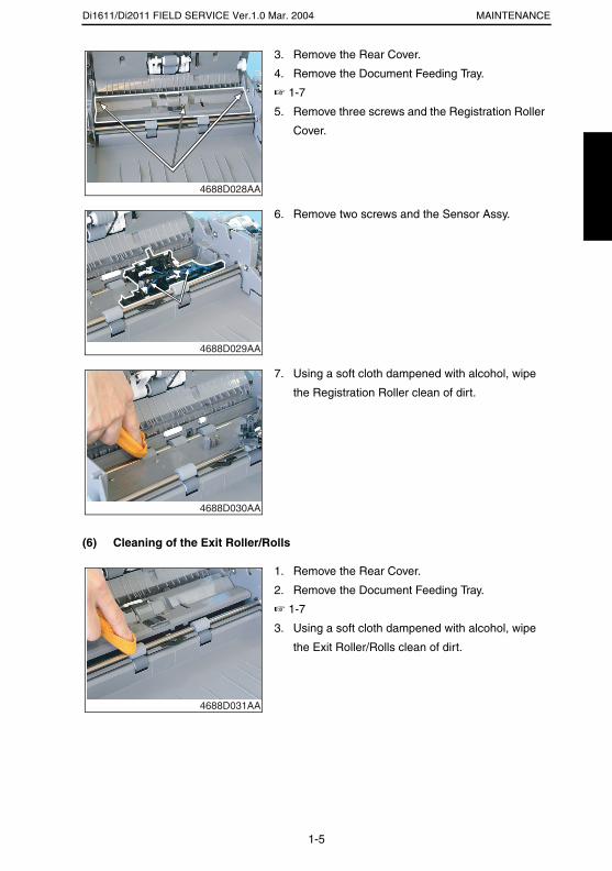
Di1611/Di2011 FIELD SERVICE Ver.1.0 Mar. 2004 MAINTENANCE
(6) Cleaning of the Exit Roller/Rolls
3. Remove the Rear Cover.
4. Remove the Document Feeding Tray.
☞ 1-7
5. Remove three screws and the Registration Roller
Cover.
4688D028AA
6. Remove two screws and the Sensor Assy.
4688D029AA
7. Using a soft cloth dampened with alcohol, wipe
the Registration Roller clean of dirt.
4688D030AA
1. Remove the Rear Cover.
2. Remove the Document Feeding Tray.
☞ 1-7
3. Using a soft cloth dampened with alcohol, wipe
the Exit Roller/Rolls clean of dirt.
4688D031AA
1-5
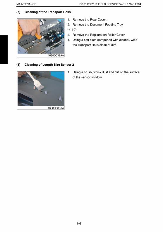
Di1611/Di2011 FIELD SERVICE Ver.1.0 Mar. 2004MAINTENANCE
(7) Cleaning of the Transport Rolls
(8) Cleaning of Length Size Sensor 2
1. Remove the Rear Cover.
2. Remove the Document Feeding Tray.
☞ 1-7
3. Remove the Registration Roller Cover.
4. Using a soft cloth dampened with alcohol, wipe
the Transport Rolls clean of dirt.
4688D032AA
1. Using a brush, whisk dust and dirt off the surface
of the sensor window.
4688D033AA
1-6
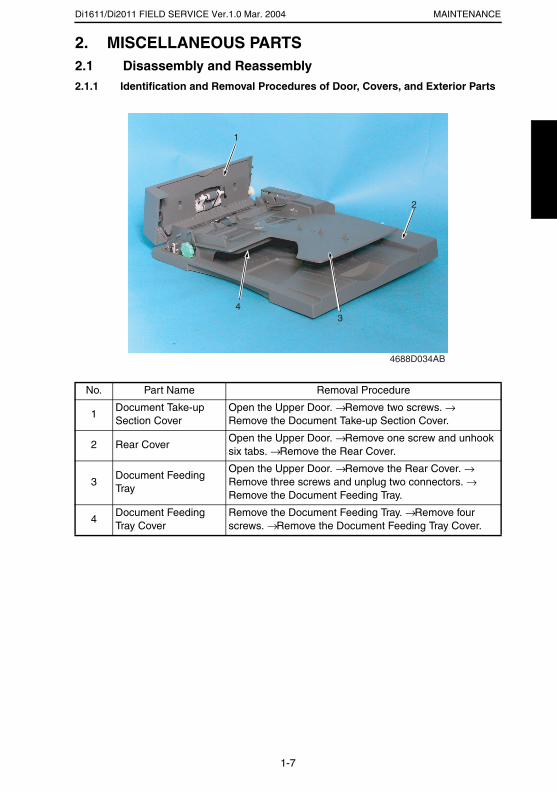
Di1611/Di2011 FIELD SERVICE Ver.1.0 Mar. 2004 MAINTENANCE
2. MISCELLANEOUS PARTS2.1 Disassembly and Reassembly2.1.1 Identification and Removal Procedures of Door, Covers, and Exterior Parts
No. Part Name Removal Procedure
1Document Take-up Section Cover
Open the Upper Door. → Remove two screws. → Remove the Document Take-up Section Cover.
2 Rear CoverOpen the Upper Door. → Remove one screw and unhook six tabs. → Remove the Rear Cover.
3Document Feeding Tray
Open the Upper Door. → Remove the Rear Cover. → Remove three screws and unplug two connectors. → Remove the Document Feeding Tray.
4Document Feeding Tray Cover
Remove the Document Feeding Tray. → Remove four screws. → Remove the Document Feeding Tray Cover.
4688D034AB
4
1
2
3
1-7
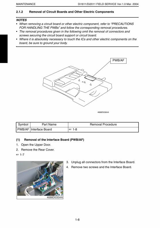
Di1611/Di2011 FIELD SERVICE Ver.1.0 Mar. 2004MAINTENANCE
2.1.2 Removal of Circuit Boards and Other Electric Components
NOTES• When removing a circuit board or other electric component, refer to “PRECAUTIONS
FOR HANDLING THE PWBs” and follow the corresponding removal procedures.• The removal procedures given in the following omit the removal of connectors and
screws securing the circuit board support or circuit board.• Where it is absolutely necessary to touch the ICs and other electric components on the
board, be sure to ground your body.
(1) Removal of the Interface Board (PWB/AF)
1. Open the Upper Door.
2. Remove the Rear Cover.
☞ 1-7
Symbol Part Name Removal Procedure
PWB/AF Interface Board ☞ 1-8
PWB/AF
4688D036AA
3. Unplug all connectors from the Interface Board.
4. Remove two screws and the Interface Board.
4688D035AA
1-8

ADJUSTING/SETTING
19971

Di1611/Di2011 FIELD SERVICE Ver.1.0 Mar. 2004ADJUSTING/SETTING
1. SERVICE MODE1.1 Service Mode Function Setting Procedure
NOTE• Care must be used to ensure that only the personnel who are involved in service jobs
know the procedure to enter the Service mode.
<Procedure>
1. Press the Utility key.
2. Press the following keys in this order.
3. Stop → 0 → 0 → Stop → 0 → 1
4. The Service mode menu screen will appear.
<Exiting the Mode>
• Press the Panel Reset key as many times as it is required to display the initial screen.
<Service Mode Function Setting Value Changing Procedure>
1. Select the desired item using [ ▲ / ▼ ] key.
2. Select the setting value using [ ▲ / ▼ ] key, [ < / > ] key, or the 10-Key Pad.
3. Validate the selection by pressing the [Yes] key.
4. To go back to previous screen, press the [No] key.
2-1
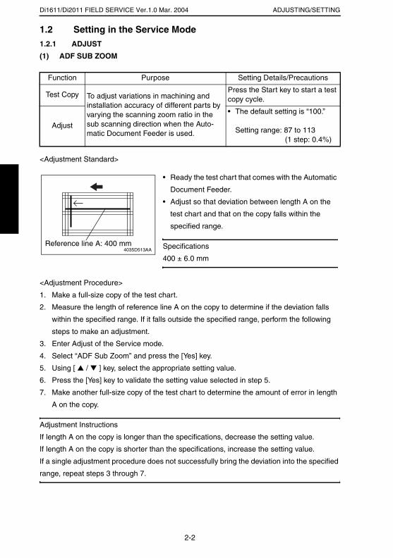
Di1611/Di2011 FIELD SERVICE Ver.1.0 Mar. 2004 ADJUSTING/SETTING
1.2 Setting in the Service Mode1.2.1 ADJUST
(1) ADF SUB ZOOM
<Adjustment Standard>
<Adjustment Procedure>
1. Make a full-size copy of the test chart.
2. Measure the length of reference line A on the copy to determine if the deviation falls
within the specified range. If it falls outside the specified range, perform the following
steps to make an adjustment.
3. Enter Adjust of the Service mode.
4. Select “ADF Sub Zoom” and press the [Yes] key.
5. Using [ ▲ / ▼ ] key, select the appropriate setting value.
6. Press the [Yes] key to validate the setting value selected in step 5.
7. Make another full-size copy of the test chart to determine the amount of error in length
A on the copy.
Adjustment Instructions
If length A on the copy is longer than the specifications, decrease the setting value.
If length A on the copy is shorter than the specifications, increase the setting value.
If a single adjustment procedure does not successfully bring the deviation into the specified
range, repeat steps 3 through 7.
Function Purpose Setting Details/Precautions
Test Copy To adjust variations in machining and installation accuracy of different parts by varying the scanning zoom ratio in the sub scanning direction when the Auto-matic Document Feeder is used.
Press the Start key to start a test copy cycle.
Adjust
• The default setting is “100.” Setting range: 87 to 113
(1 step: 0.4%)
• Ready the test chart that comes with the Automatic
Document Feeder.
• Adjust so that deviation between length A on the
test chart and that on the copy falls within the
specified range.
Specifications
400 ± 6.0 mm4035D513AA
Reference line A: 400 mm
2-2
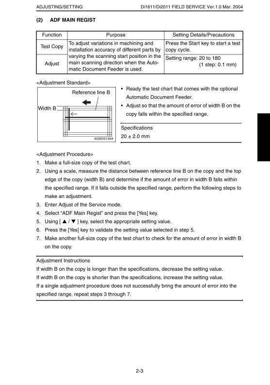
Di1611/Di2011 FIELD SERVICE Ver.1.0 Mar. 2004ADJUSTING/SETTING
(2) ADF MAIN REGIST
<Adjustment Standard>
<Adjustment Procedure>
1. Make a full-size copy of the test chart.
2. Using a scale, measure the distance between reference line B on the copy and the top
edge of the copy (width B) and determine if the amount of error in width B falls within
the specified range. If it falls outside the specified range, perform the following steps to
make an adjustment.
3. Enter Adjust of the Service mode.
4. Select “ADF Main Regist” and press the [Yes] key.
5. Using [ ▲ / ▼ ] key, select the appropriate setting value.
6. Press the [Yes] key to validate the setting value selected in step 5.
7. Make another full-size copy of the test chart to check for the amount of error in width B
on the copy.
Adjustment Instructions
If width B on the copy is longer than the specifications, decrease the setting value.
If width B on the copy is shorter than the specifications, increase the setting value.
If a single adjustment procedure does not successfully bring the amount of error into the
specified range, repeat steps 3 through 7.
Function Purpose Setting Details/Precautions
Test CopyTo adjust variations in machining and installation accuracy of different parts by varying the scanning start position in the main scanning direction when the Auto-matic Document Feeder is used.
Press the Start key to start a test copy cycle.
AdjustSetting range: 20 to 180
(1 step: 0.1 mm)
• Ready the test chart that comes with the optional
Automatic Document Feeder.
• Adjust so that the amount of error of width B on the
copy falls within the specified range.
Specifications
20 ± 2.0 mm4035D513AA
Reference line B
Width B
2-3
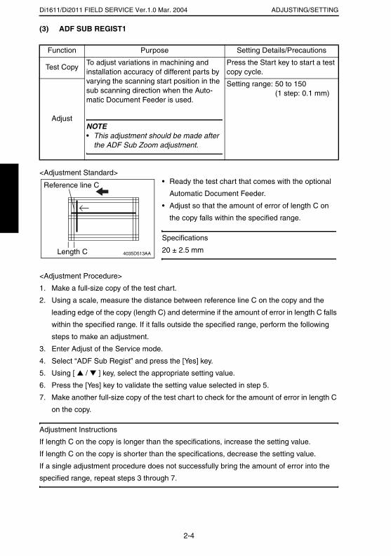
Di1611/Di2011 FIELD SERVICE Ver.1.0 Mar. 2004 ADJUSTING/SETTING
(3) ADF SUB REGIST1
<Adjustment Standard>
<Adjustment Procedure>
1. Make a full-size copy of the test chart.
2. Using a scale, measure the distance between reference line C on the copy and the
leading edge of the copy (length C) and determine if the amount of error in length C falls
within the specified range. If it falls outside the specified range, perform the following
steps to make an adjustment.
3. Enter Adjust of the Service mode.
4. Select “ADF Sub Regist” and press the [Yes] key.
5. Using [ ▲ / ▼ ] key, select the appropriate setting value.
6. Press the [Yes] key to validate the setting value selected in step 5.
7. Make another full-size copy of the test chart to check for the amount of error in length C
on the copy.
Adjustment Instructions
If length C on the copy is longer than the specifications, increase the setting value.
If length C on the copy is shorter than the specifications, decrease the setting value.
If a single adjustment procedure does not successfully bring the amount of error into the
specified range, repeat steps 3 through 7.
Function Purpose Setting Details/Precautions
Test CopyTo adjust variations in machining and installation accuracy of different parts by varying the scanning start position in the sub scanning direction when the Auto-matic Document Feeder is used.
NOTE• This adjustment should be made after
the ADF Sub Zoom adjustment.
Press the Start key to start a test copy cycle.
Adjust
Setting range: 50 to 150 (1 step: 0.1 mm)
• Ready the test chart that comes with the optional
Automatic Document Feeder.
• Adjust so that the amount of error of length C on
the copy falls within the specified range.
Specifications
20 ± 2.5 mm4035D513AALength C
Reference line C
2-4
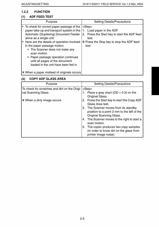
Di1611/Di2011 FIELD SERVICE Ver.1.0 Mar. 2004ADJUSTING/SETTING
1.2.2 FUNCTION
(1) ADF FEED TEST
(2) COPY ADF GLASS AREA
Purpose Setting Details/Precautions
• To check for correct paper passage of the paper take-up and transport system in the Automatic (Duplexing) Document Feeder alone as a single unit.
• Here are the details of operation involved in the paper passage motion.
• The Scanner does not make any scan motion.
• Paper passage operation continues until all pages of the document loaded in the unit have been fed in.
✽ When a paper misfeed of originals occurs
<Step>1. Load paper in the ADF.2. Press the Start key to start the ADF feed
test.✽ Press the Stop key to stop the ADF feed
test.
Purpose Setting Details/Precautions
To check for scratches and dirt on the Origi-nal Scanning Glass.
✽ When a dirty image occurs
<Step>1. Place a gray chart (OD = 0.3) on the
Original Glass.2. Press the Start key to start the Copy ADF
Glass Area test.3. The Scanner moves from its standby
position to a point 2 mm to the left of the Original Scanning Glass.
4. The Scanner moves to the right to start a scan motion.
5. The copier produces two copy samples (in order to know dirt on the glass from printer image noise).
2-5
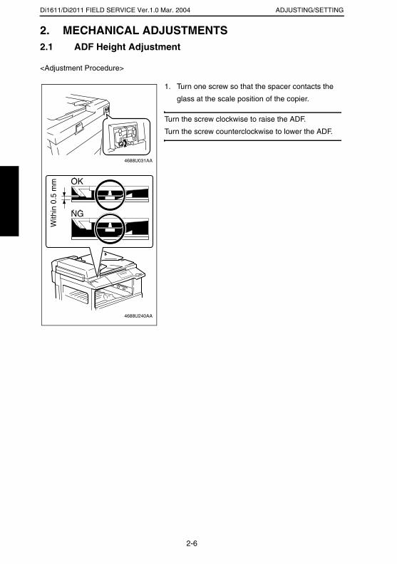
Di1611/Di2011 FIELD SERVICE Ver.1.0 Mar. 2004 ADJUSTING/SETTING
2. MECHANICAL ADJUSTMENTS2.1 ADF Height Adjustment
<Adjustment Procedure>
1. Turn one screw so that the spacer contacts the
glass at the scale position of the copier.
Turn the screw clockwise to raise the ADF.
Turn the screw counterclockwise to lower the ADF.
4688U031AA
4688U240AA
With
in 0
.5 m
m
2-6
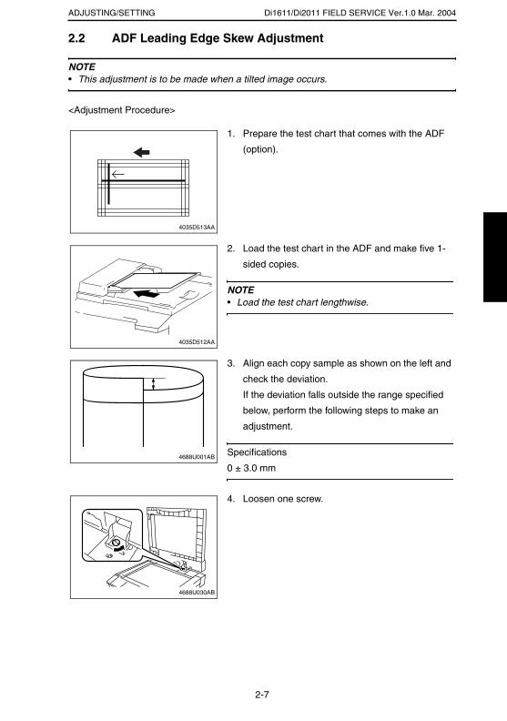
Di1611/Di2011 FIELD SERVICE Ver.1.0 Mar. 2004ADJUSTING/SETTING
2.2 ADF Leading Edge Skew Adjustment
NOTE• This adjustment is to be made when a tilted image occurs.
<Adjustment Procedure>
1. Prepare the test chart that comes with the ADF
(option).
4035D513AA
2. Load the test chart in the ADF and make five 1-
sided copies.
NOTE• Load the test chart lengthwise.
4035D512AA
3. Align each copy sample as shown on the left and
check the deviation.
If the deviation falls outside the range specified
below, perform the following steps to make an
adjustment.
Specifications
0 ± 3.0 mm4688U001AB
4. Loosen one screw.
4688U030AB
2-7

Di1611/Di2011 FIELD SERVICE Ver.1.0 Mar. 2004 ADJUSTING/SETTING
5. If the deviation is as shown on the left, move the
graduations of the ADF to the front.
4688U001AB
4688U206AA
6. If the deviation is as shown on the left, move the
graduations of the ADF to the rear.
4688U002AB
4688U207AA
7. Tighten the screw.
4688U030AB
2-8

TROUBLESHOOTING
19971

Di1611/Di2011 FIELD SERVICE Ver.1.0 Mar. 2004 TROUBLESHOOTING
3. INTRODUCTION
• Information required for troubleshooting and steps that must be performed are described
in this chapter.
3.1 Electrical Components Check Procedure• If a paper misfeed or malfunction occurs, perform the following operations to check the
condition of the electrical components.
3.1.1 Sensor
Step Check Result Action
1 Does the input signal of the control board change when the sensor light is interrupted? (H → L, L → H)
NO Replace the sensor.
YES Replace the control board.
4025T520AA
4025T521AA
3-1

Di1611/Di2011 FIELD SERVICE Ver.1.0 Mar. 2004TROUBLESHOOTING
3.1.2 Switch
3.1.3 Solenoid
3.1.4 Clutch
Step Check Result Action
1 Does the input signal (NO) of the control board change from L to H when the switch is activated?
NO Replace the switch.
YES Replace the control board.
Step Check Result Action
1 Does the output signal of the control board change from H to L when the solenoid is activated?
NO Replace the control board.
YES Replace the solenoid.
Step Check Result Action
1 Does the output signal of the control board change from H to L when the clutch is activated?
NO Replace the control board.
YES Replace the clutch.
Not UseCOM
NO
4025T523AB
12
212
1
4025T522AA
4025T528AA
3-2

Di1611/Di2011 FIELD SERVICE Ver.1.0 Mar. 2004 TROUBLESHOOTING
3.1.5 Motor
Step Check Result Action
1 Does the LOCK signal switch to H when the machine goes into standby?
NO Replace the con-trol board. Replace the motor.
2 Does the REM signal of the master board change from H to L when the motor is turned on?
YES Replace the motor.
NO Replace the con-trol board.
Step Check Result Action
1 Does the input signal of the master board change from H to L when the motor is turned on?(The input signal differs depending on the rotation direction.)
YES Replace the motor.
NO Replace the con-trol board.
Step Check Result Action
1 Are the relay connector of the motor and the print jack of the control board correctly connected?
YES Replace the motor or the control board.
NO Connect the con-nector or the print jack.
GND
REM
LOCK
2
1
3
4025T526AA
4025T525AA
4025T527AA
3-3

Di1611/Di2011 FIELD SERVICE Ver.1.0 Mar. 2004TROUBLESHOOTING
4. MISFEEDS4.1 Initial Checks• When a paper misfeed occurs, first perform the following initial checks.
4.2 Paper Misfeed Detection4.2.1 Outline
• A paper misfeed is detected by detecting different states of signals (H, L) of several sen-
sors located near the paper take-up section and the Exit Paper Sensor. The copier
thereby determines whether there is paper left inside it.
• The timings of the rising and falling edges of the paper take-up-related sensors and the
Exit Paper Sensor are monitored to detect a misfeed of paper being fed through the
copier.
• The states (H, L) of the paper take-up-related sensors and the Exit Paper Sensor are
monitored to detect a sheet of paper left in the copier.
• All drives are brought to a stop when a sheet of paper misfed or left in the copier is
detected.
Check Item Action
Does paper meet product specifications? Replace paper.
Is the paper curled, wavy, or damp? Replace paper.Instruct the user on the correct paper storage procedures.
Is a foreign object present along the paper path, or is the paper path deformed or worn?
Clean or change the paper path.
Are the Paper Separator Fingers dirty, deformed, or worn?
Clean or replace the defective Paper Separator Finger.
Are rolls/rollers dirty, deformed, or worn? Clean or replace the defective roll/roller.
Are the Edge Guide and Trailing Edge Stop at the correct position to accommodate the paper?
Set as necessary.
Are the actuators operational and checked for correct operation?
Correct or replace the defective actua-tor.
3-4
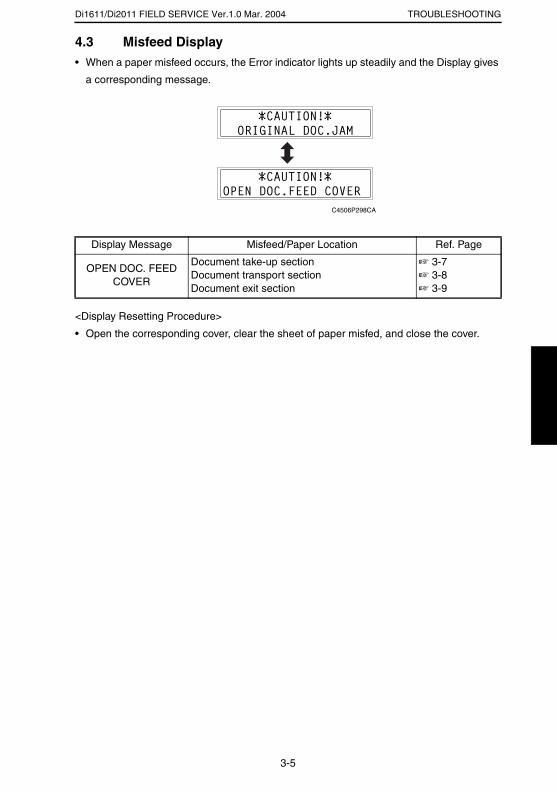
Di1611/Di2011 FIELD SERVICE Ver.1.0 Mar. 2004 TROUBLESHOOTING
4.3 Misfeed Display• When a paper misfeed occurs, the Error indicator lights up steadily and the Display gives
a corresponding message.
<Display Resetting Procedure>
• Open the corresponding cover, clear the sheet of paper misfed, and close the cover.
Display Message Misfeed/Paper Location Ref. Page
OPEN DOC. FEED COVER
Document take-up sectionDocument transport sectionDocument exit section
☞ 3-7☞ 3-8☞ 3-9
C4506P298CA
3-5
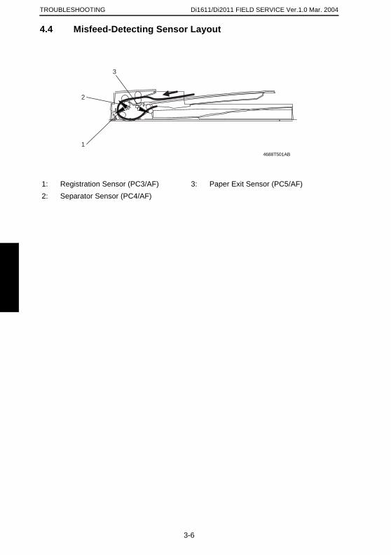
TROUBLESHOOTING
4.4 Misfeed-D
1: Registration Sen2: Separator Senso
1
2
3
Di1611/Di2011 FIELD SERVICE Ver.1.0 Mar. 2004
etecting Sensor Layout
sor (PC3/AF) 3: Paper Exit Sensor (PC5/AF)r (PC4/AF)
4688T501AB
3-6
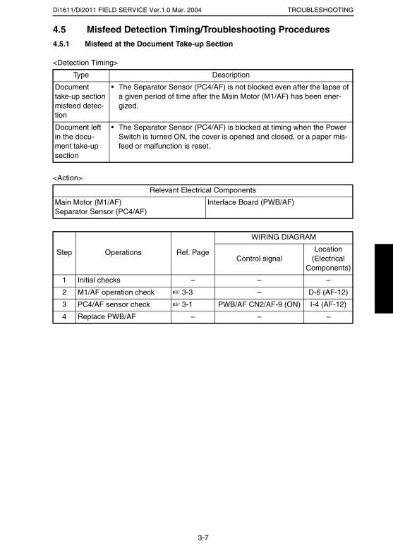
Di1611/Di2011 FIELD SERVICE Ver.1.0 Mar. 2004 TROUBLESHOOTING
4.5 Misfeed Detection Timing/Troubleshooting Procedures4.5.1 Misfeed at the Document Take-up Section
<Detection Timing>
<Action>
Type Description
Document take-up section misfeed detec-tion
• The Separator Sensor (PC4/AF) is not blocked even after the lapse of a given period of time after the Main Motor (M1/AF) has been ener-gized.
Document left in the docu-ment take-up section
• The Separator Sensor (PC4/AF) is blocked at timing when the Power Switch is turned ON, the cover is opened and closed, or a paper mis-feed or malfunction is reset.
Relevant Electrical Components
Main Motor (M1/AF)Separator Sensor (PC4/AF)
Interface Board (PWB/AF)
Step Operations Ref. Page
WIRING DIAGRAM
Control signalLocation
(Electrical Components)
1 Initial checks – – –
2 M1/AF operation check ☞ 3-3 – D-6 (AF-12)
3 PC4/AF sensor check ☞ 3-1 PWB/AF CN2/AF-9 (ON) I-4 (AF-12)
4 Replace PWB/AF – – –
3-7

Di1611/Di2011 FIELD SERVICE Ver.1.0 Mar. 2004TROUBLESHOOTING
4.5.2 Misfeed at the Document Transport Section
<Detection Timing>
<Action>
Type Description
Document transport sec-tion misfeed detection
• The Registration Sensor (PC3/AF) is not blocked even after the lapse of a given period of time after the Main Motor (M1/AF) has been ener-gized.
Document left in the docu-ment transport section
• The Registration Sensor (PC3/AF) is blocked at timing when the Power Switch is turned ON, the cover is opened and closed, or a paper misfeed or malfunction is reset.
Relevant Electrical Components
Main Motor (M1/AF)Registration Sensor (PC3/AF)
Interface Board (PWB/AF)
Step Operations Ref. Page
WIRING DIAGRAM
Control signalLocation
(Electrical Components)
1 Initial checks – – –
2 M1/AF operation check ☞ 3-3 – D-6 (AF-12)
3 PC3/AF sensor check ☞ 3-1 PWB/AF CN2/AF-6 (ON) H-4 (AF-12)
4 Replace PWB/AF – – –
3-8

Di1611/Di2011 FIELD SERVICE Ver.1.0 Mar. 2004 TROUBLESHOOTING
4.5.3 Misfeed at the Document Exit Section
<Detection Timing>
<Action>
Type Description
Document exit section mis-feed detection
• The Paper Exit Sensor (PC5/AF) is not blocked even after the lapse of a given period of time after the Main Motor (M1/AF) has been ener-gized.
Document left in the docu-ment exit sec-tion
• The Paper Exit Sensor (PC5/AF) is blocked at timing when the Power Switch is turned ON, the cover is opened and closed, or a paper mis-feed or malfunction is reset.
Relevant Electrical Components
Main Motor (M1/AF)Paper Exit Sensor (PC5/AF)
Interface Board (PWB/AF)
Step Operations Ref. Page
WIRING DIAGRAM
Control signalLocation
(Electrical Components)
1 Initial checks – – –
2 M1/AF operation check ☞ 3-3 – D-6 (AF-12)
3 PC5/AF sensor check ☞ 3-1 PWB/AF CN2/AF-12 (ON) H-6 (AF-12)
4 Replace PWB/AF – – –
3-9

SERVICE MANUAL
2004.3Ver. 1.0
FIELD SERVICE
AFR-19

INDEX
ADJUSTMENT/SETTING
MAINTENANCE
TROUBLESHOOTING
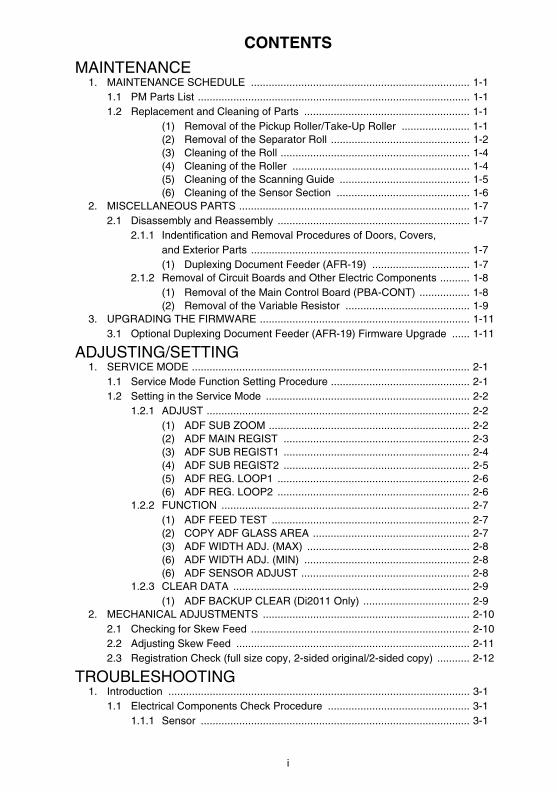
CONTENTS
MAINTENANCE1. MAINTENANCE SCHEDULE .......................................................................... 1-1
1.1 PM Parts List ............................................................................................ 1-11.2 Replacement and Cleaning of Parts ........................................................ 1-1
(1) Removal of the Pickup Roller/Take-Up Roller ....................... 1-1(2) Removal of the Separator Roll ............................................... 1-2(3) Cleaning of the Roll ................................................................ 1-4(4) Cleaning of the Roller ............................................................ 1-4(5) Cleaning of the Scanning Guide ............................................ 1-5(6) Cleaning of the Sensor Section ............................................. 1-6
2. MISCELLANEOUS PARTS .............................................................................. 1-72.1 Disassembly and Reassembly ................................................................. 1-7
2.1.1 Indentification and Removal Procedures of Doors, Covers, and Exterior Parts .......................................................................... 1-7(1) Duplexing Document Feeder (AFR-19) ................................. 1-7
2.1.2 Removal of Circuit Boards and Other Electric Components .......... 1-8(1) Removal of the Main Control Board (PBA-CONT) ................. 1-8(2) Removal of the Variable Resistor .......................................... 1-9
3. UPGRADING THE FIRMWARE ....................................................................... 1-113.1 Optional Duplexing Document Feeder (AFR-19) Firmware Upgrade ...... 1-11
ADJUSTING/SETTING1. SERVICE MODE .............................................................................................. 2-1
1.1 Service Mode Function Setting Procedure ............................................... 2-11.2 Setting in the Service Mode ..................................................................... 2-2
1.2.1 ADJUST ......................................................................................... 2-2(1) ADF SUB ZOOM .................................................................... 2-2(2) ADF MAIN REGIST ............................................................... 2-3(3) ADF SUB REGIST1 ............................................................... 2-4(4) ADF SUB REGIST2 ............................................................... 2-5(5) ADF REG. LOOP1 ................................................................. 2-6(6) ADF REG. LOOP2 ................................................................. 2-6
1.2.2 FUNCTION .................................................................................... 2-7(1) ADF FEED TEST ................................................................... 2-7(2) COPY ADF GLASS AREA ..................................................... 2-7(3) ADF WIDTH ADJ. (MAX) ....................................................... 2-8(6) ADF WIDTH ADJ. (MIN) ........................................................ 2-8(6) ADF SENSOR ADJUST ......................................................... 2-8
1.2.3 CLEAR DATA ................................................................................ 2-9(1) ADF BACKUP CLEAR (Di2011 Only) .................................... 2-9
2. MECHANICAL ADJUSTMENTS ...................................................................... 2-102.1 Checking for Skew Feed .......................................................................... 2-102.2 Adjusting Skew Feed ............................................................................... 2-112.3 Registration Check (full size copy, 2-sided original/2-sided copy) ........... 2-12
TROUBLESHOOTING1. Introduction ...................................................................................................... 3-1
1.1 Electrical Components Check Procedure ................................................ 3-11.1.1 Sensor ........................................................................................... 3-1
i
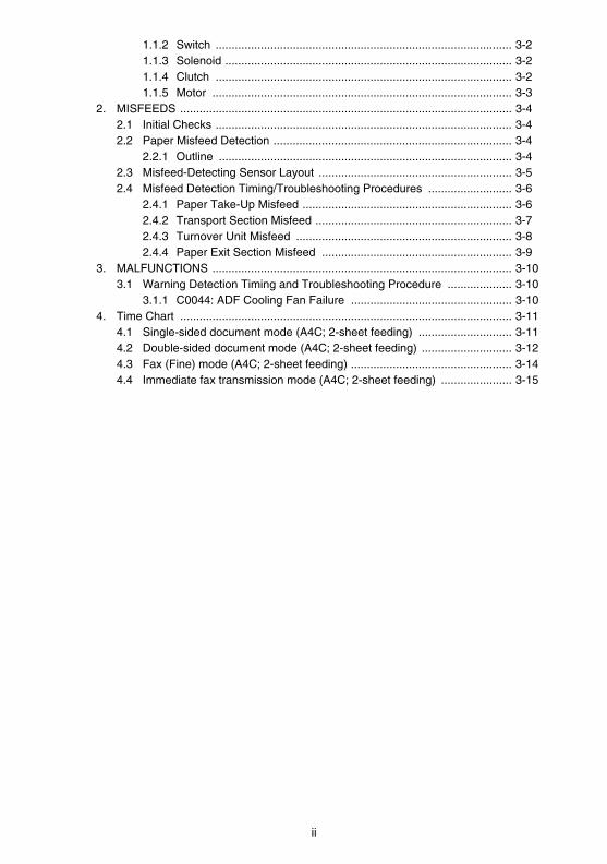
1.1.2 Switch ............................................................................................ 3-21.1.3 Solenoid ......................................................................................... 3-21.1.4 Clutch ............................................................................................ 3-21.1.5 Motor ............................................................................................. 3-3
2. MISFEEDS ....................................................................................................... 3-42.1 Initial Checks ............................................................................................ 3-42.2 Paper Misfeed Detection .......................................................................... 3-4
2.2.1 Outline ........................................................................................... 3-42.3 Misfeed-Detecting Sensor Layout ............................................................ 3-52.4 Misfeed Detection Timing/Troubleshooting Procedures .......................... 3-6
2.4.1 Paper Take-Up Misfeed ................................................................. 3-62.4.2 Transport Section Misfeed ............................................................. 3-72.4.3 Turnover Unit Misfeed ................................................................... 3-82.4.4 Paper Exit Section Misfeed ........................................................... 3-9
3. MALFUNCTIONS ............................................................................................. 3-103.1 Warning Detection Timing and Troubleshooting Procedure .................... 3-10
3.1.1 C0044: ADF Cooling Fan Failure .................................................. 3-104. Time Chart ....................................................................................................... 3-11
4.1 Single-sided document mode (A4C; 2-sheet feeding) ............................. 3-114.2 Double-sided document mode (A4C; 2-sheet feeding) ............................ 3-124.3 Fax (Fine) mode (A4C; 2-sheet feeding) .................................................. 3-144.4 Immediate fax transmission mode (A4C; 2-sheet feeding) ...................... 3-15
ii

MAINTENANCE
19971
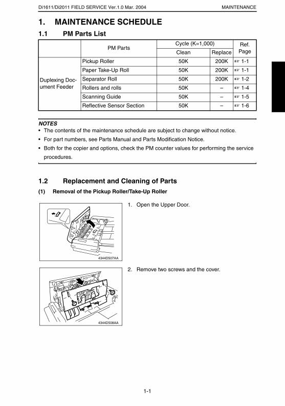
Di1611/Di2011 FIELD SERVICE Ver.1.0 Mar. 2004 MAINTENANCE
1. MAINTENANCE SCHEDULE1.1 PM Parts List
NOTES• The contents of the maintenance schedule are subject to change without notice.
• For part numbers, see Parts Manual and Parts Modification Notice.
• Both for the copier and options, check the PM counter values for performing the service
procedures.
1.2 Replacement and Cleaning of Parts(1) Removal of the Pickup Roller/Take-Up Roller
PM PartsCycle (K=1,000) Ref.
PageClean Replace
Duplexing Doc-ument Feeder
Pickup Roller 50K 200K ☞ 1-1
Paper Take-Up Roll 50K 200K ☞ 1-1
Separator Roll 50K 200K ☞ 1-2
Rollers and rolls 50K – ☞ 1-4
Scanning Guide 50K – ☞ 1-5
Reflective Sensor Section 50K – ☞ 1-6
1. Open the Upper Door.
4344D507AA
2. Remove two screws and the cover.
4344D508AA
1-1
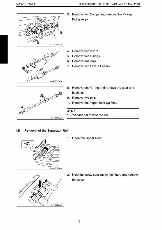
Di1611/Di2011 FIELD SERVICE Ver.1.0 Mar. 2004MAINTENANCE
(2) Removal of the Separator Roll
3. Remove two C-clips and remove the Pickup
Roller Assy.
4344D514AA
4. Remove two levers.
5. Remove five C rings.
6. Remove one arm.
7. Remove two Pickup Rollers.
4344D515AA
8. Remove one C-ring and remove the gear and
bushing.
9. Remove two pins.
10. Remove the Paper Take-Up Roll.
NOTE• Use care not to lose the pin.
4344D516AA
1. Open the Upper Door.
4344D507AA
2. Hold the arrow sections in the figure and remove
the cover.
4344D509AA
1-2
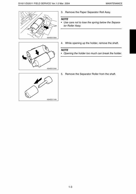
Di1611/Di2011 FIELD SERVICE Ver.1.0 Mar. 2004 MAINTENANCE
3. Remove the Paper Separator Roll Assy.
NOTE• Use care not to lose the spring below the Separa-
tor Roller Assy.
4344D513AA
4. While opening up the holder, remove the shaft.
NOTE• Opening the holder too much can break the holder.
4344D512AA
5. Remove the Separator Roller from the shaft.
4344D511AA
1-3
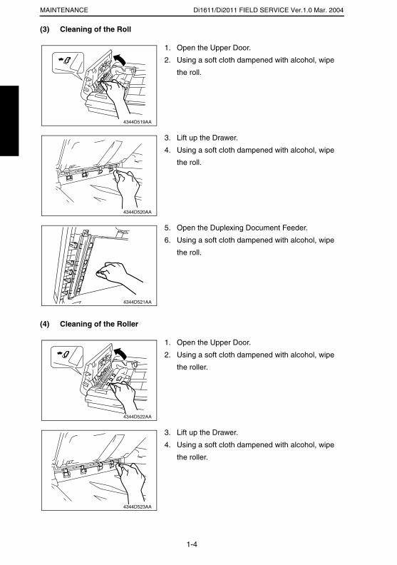
Di1611/Di2011 FIELD SERVICE Ver.1.0 Mar. 2004MAINTENANCE
(3) Cleaning of the Roll
(4) Cleaning of the Roller
1. Open the Upper Door.
2. Using a soft cloth dampened with alcohol, wipe
the roll.
4344D519AA
3. Lift up the Drawer.
4. Using a soft cloth dampened with alcohol, wipe
the roll.
4344D520AA
5. Open the Duplexing Document Feeder.
6. Using a soft cloth dampened with alcohol, wipe
the roll.
4344D521AA
1. Open the Upper Door.
2. Using a soft cloth dampened with alcohol, wipe
the roller.
4344D522AA
3. Lift up the Drawer.
4. Using a soft cloth dampened with alcohol, wipe
the roller.
4344D523AA
1-4
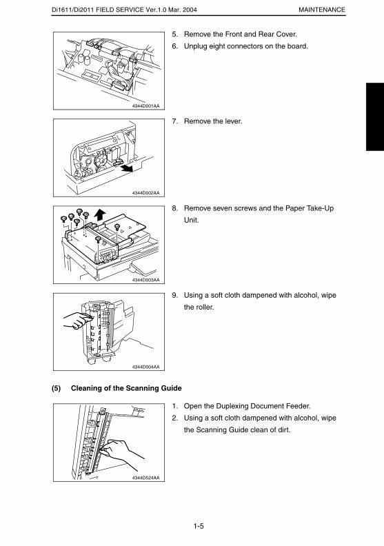
Di1611/Di2011 FIELD SERVICE Ver.1.0 Mar. 2004 MAINTENANCE
(5) Cleaning of the Scanning Guide
5. Remove the Front and Rear Cover.
6. Unplug eight connectors on the board.
4344D001AA
7. Remove the lever.
4344D002AA
8. Remove seven screws and the Paper Take-Up
Unit.
4344D003AA
9. Using a soft cloth dampened with alcohol, wipe
the roller.
4344D004AA
1. Open the Duplexing Document Feeder.
2. Using a soft cloth dampened with alcohol, wipe
the Scanning Guide clean of dirt.
4344D524AA
1-5
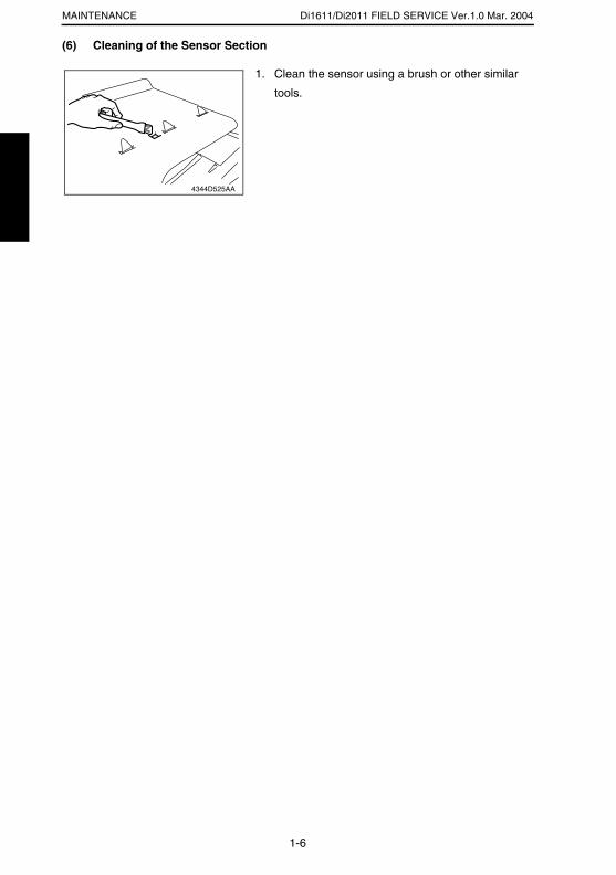
Di1611/Di2011 FIELD SERVICE Ver.1.0 Mar. 2004MAINTENANCE
(6) Cleaning of the Sensor Section
1. Clean the sensor using a brush or other similar
tools.
4344D525AA
1-6
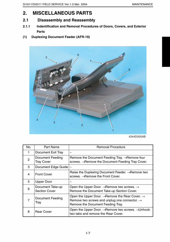
Di1611/Di2011 FIELD SERVICE Ver.1.0 Mar. 2004 MAINTENANCE
2. MISCELLANEOUS PARTS2.1 Disassembly and Reassembly2.1.1 Indentification and Removal Procedures of Doors, Covers, and Exterior
Parts
(1) Duplexing Document Feeder (AFR-19)
No. Part Name Removal Procedure
1 Document Exit Tray –
2Document Feeding Tray Cover
Remove the Document Feeding Tray. → Remove four screws. → Remove the Document Feeding Tray Cover.
3 Document Edge Guide –
4 Front CoverRaise the Duplexing Document Feeder. → Remove two screws. → Remove the Front Cover.
5 Upper Door –
6Document Take-up Section Cover
Open the Upper Door. → Remove two screws. → Remove the Document Take-up Section Cover.
7Document Feeding Tray
Open the Upper Door. → Remove the Rear Cover. → Remove two screws and unplug one connector. → Remove the Document Feeding Tray.
8 Rear CoverOpen the Upper Door. → Remove two screws. → Unhook two tabs and remove the Rear Cover.
4344D005AB
1
23
4
56
7
8
1-7
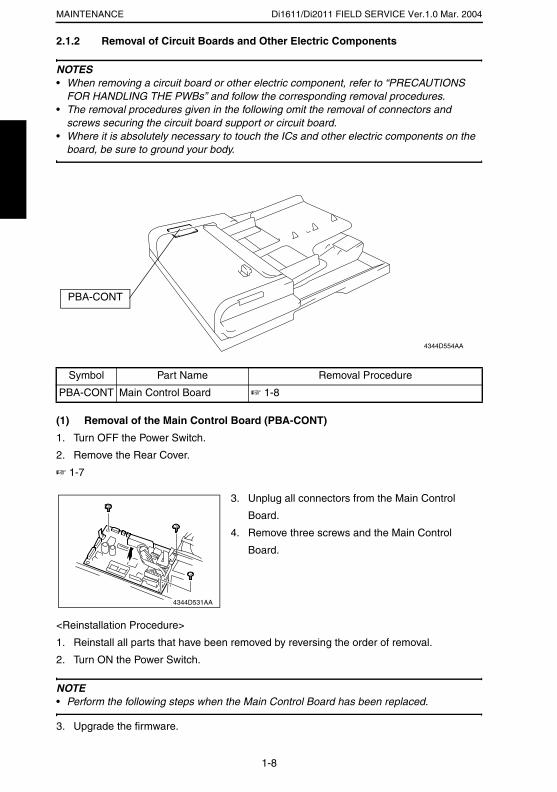
Di1611/Di2011 FIELD SERVICE Ver.1.0 Mar. 2004MAINTENANCE
2.1.2 Removal of Circuit Boards and Other Electric Components
NOTES• When removing a circuit board or other electric component, refer to “PRECAUTIONS
FOR HANDLING THE PWBs” and follow the corresponding removal procedures.• The removal procedures given in the following omit the removal of connectors and
screws securing the circuit board support or circuit board.• Where it is absolutely necessary to touch the ICs and other electric components on the
board, be sure to ground your body.
(1) Removal of the Main Control Board (PBA-CONT)
1. Turn OFF the Power Switch.
2. Remove the Rear Cover.
☞ 1-7
<Reinstallation Procedure>
1. Reinstall all parts that have been removed by reversing the order of removal.
2. Turn ON the Power Switch.
NOTE• Perform the following steps when the Main Control Board has been replaced.
3. Upgrade the firmware.
Symbol Part Name Removal Procedure
PBA-CONT Main Control Board ☞ 1-8
PBA-CONT
4344D554AA
3. Unplug all connectors from the Main Control
Board.
4. Remove three screws and the Main Control
Board.
4344D531AA
1-8
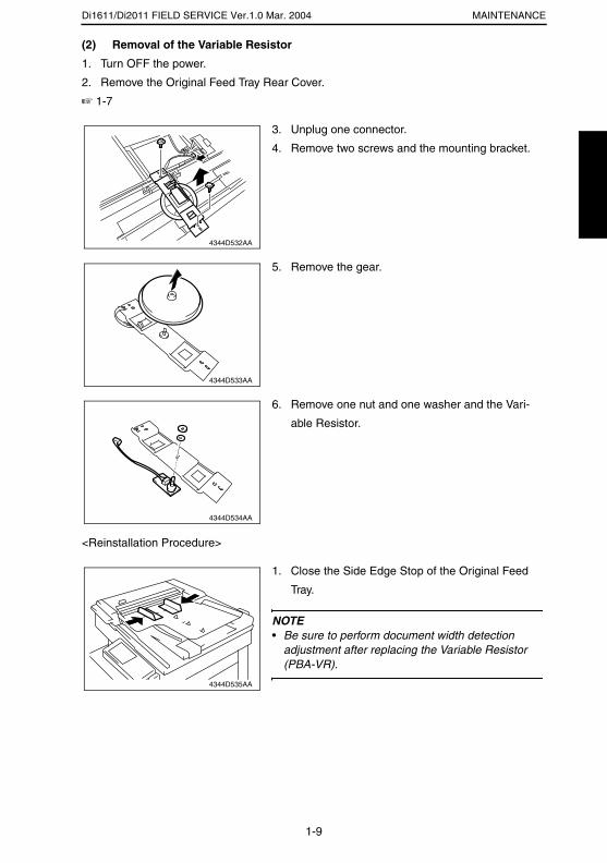
Di1611/Di2011 FIELD SERVICE Ver.1.0 Mar. 2004 MAINTENANCE
(2) Removal of the Variable Resistor
1. Turn OFF the power.
2. Remove the Original Feed Tray Rear Cover.
☞ 1-7
<Reinstallation Procedure>
3. Unplug one connector.
4. Remove two screws and the mounting bracket.
4344D532AA
5. Remove the gear.
4344D533AA
6. Remove one nut and one washer and the Vari-
able Resistor.
4344D534AA
1. Close the Side Edge Stop of the Original Feed
Tray.
NOTE• Be sure to perform document width detection
adjustment after replacing the Variable Resistor (PBA-VR).
4344D535AA
1-9
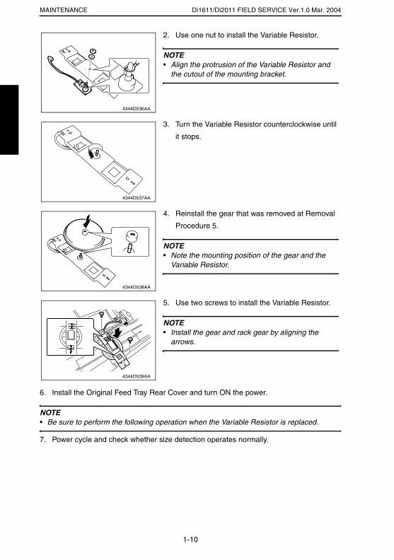
Di1611/Di2011 FIELD SERVICE Ver.1.0 Mar. 2004MAINTENANCE
6. Install the Original Feed Tray Rear Cover and turn ON the power.
NOTE• Be sure to perform the following operation when the Variable Resistor is replaced.
7. Power cycle and check whether size detection operates normally.
2. Use one nut to install the Variable Resistor.
NOTE• Align the protrusion of the Variable Resistor and
the cutout of the mounting bracket.
4344D536AA
3. Turn the Variable Resistor counterclockwise until
it stops.
4344D537AA
4. Reinstall the gear that was removed at Removal
Procedure 5.
NOTE• Note the mounting position of the gear and the
Variable Resistor.
4344D538AA
5. Use two screws to install the Variable Resistor.
NOTE• Install the gear and rack gear by aligning the
arrows.
4344D539AA
1-10
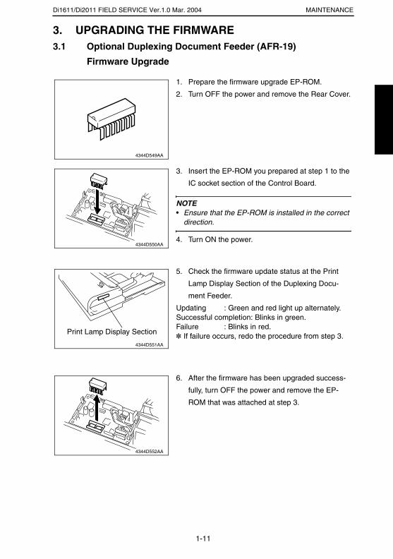
Di1611/Di2011 FIELD SERVICE Ver.1.0 Mar. 2004 MAINTENANCE
3. UPGRADING THE FIRMWARE3.1 Optional Duplexing Document Feeder (AFR-19)
Firmware Upgrade
1. Prepare the firmware upgrade EP-ROM.
2. Turn OFF the power and remove the Rear Cover.
4344D549AA
3. Insert the EP-ROM you prepared at step 1 to the
IC socket section of the Control Board.
NOTE• Ensure that the EP-ROM is installed in the correct
direction.
4. Turn ON the power.4344D550AA
5. Check the firmware update status at the Print
Lamp Display Section of the Duplexing Docu-
ment Feeder.
Updating : Green and red light up alternately. Successful completion: Blinks in green. Failure : Blinks in red.✽ If failure occurs, redo the procedure from step 3.
4344D551AA
Print Lamp Display Section
6. After the firmware has been upgraded success-
fully, turn OFF the power and remove the EP-
ROM that was attached at step 3.
4344D552AA
1-11
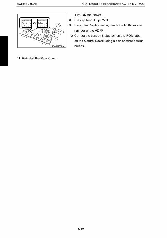
Di1611/Di2011 FIELD SERVICE Ver.1.0 Mar. 2004MAINTENANCE
11. Reinstall the Rear Cover.
7. Turn ON the power.
8. Display Tech. Rep. Mode.
9. Using the Display menu, check the ROM version
number of the ADFR.
10. Correct the version indication on the ROM label
on the Control Board using a pen or other similar
means.4344D553AA
1-12

ADJUSTING/SETTING
19971

Di1611/Di2011 FIELD SERVICE Ver.1.0 Mar. 2004ADJUSTING/SETTING
1. SERVICE MODE1.1 Service Mode Function Setting Procedure
NOTE• Care must be used to ensure that only the personnel who are involved in service jobs
know the procedure to enter the Service mode.
<Procedure>
1. Press the Utility key.
2. Press the following keys in this order.
3. Stop → 0 → 0 → Stop → 0 → 1
4. The Service mode menu screen will appear.
<Exiting the Mode>
• Press the Panel Reset key as many times as it is required to display the initial screen.
<Service Mode Function Setting Value Changing Procedure>
1. Select the desired item using [ ▲ / ▼ ] key.
2. Select the setting value using [ ▲ / ▼ ] key, [ < / > ] key, or the 10-Key Pad.
3. Validate the selection by pressing the [Yes] key.
4. To go back to previous screen, press the [No] key.
2-1

Di1611/Di2011 FIELD SERVICE Ver.1.0 Mar. 2004 ADJUSTING/SETTING
1.2 Setting in the Service Mode1.2.1 ADJUST
(1) ADF SUB ZOOM
<Adjustment Standard>
<Adjustment Procedure>
1. Make a full-size copy of the test chart.
2. Measure the length of reference line A on the copy to determine if the deviation falls
within the specified range. If it falls outside the specified range, perform the following
steps to make an adjustment.
3. Enter Adjust of the Service mode.
4. Select “ADF Sub Zoom” and press the [Yes] key.
5. Using [ ▲ / ▼ ] key, select the appropriate setting value.
6. Press the [Yes] key to validate the setting value selected in step 5.
7. Make another full-size copy of the test chart to determine the amount of error in length
A on the copy.
Adjustment Instructions
If length A on the copy is longer than the specifications, decrease the setting value.
If length A on the copy is shorter than the specifications, increase the setting value.
If a single adjustment procedure does not successfully bring the deviation into the specified
range, repeat steps 3 through 7.
Function Purpose Setting Details/Precautions
Test Copy To adjust variations in machining and installation accuracy of different parts by varying the scanning zoom ratio in the sub scanning direction when the Auto-matic Document Feeder is used.
Press the Start key to start a test copy cycle.
Adjust
• The default setting is “100.” Setting range: 87 to 113
(1 step: 0.4%)
• Ready the test chart that comes with the Automatic
Document Feeder.
• Adjust so that deviation between length A on the
test chart and that on the copy falls within the
specified range.
Specifications
400 ± 6.0 mm4035D513AA
Reference line A: 400 mm
2-2

Di1611/Di2011 FIELD SERVICE Ver.1.0 Mar. 2004ADJUSTING/SETTING
(2) ADF MAIN REGIST
<Adjustment Standard>
<Adjustment Procedure>
1. Make a full-size copy of the test chart.
2. Using a scale, measure the distance between reference line B on the copy and the top
edge of the copy (width B) and determine if the amount of error in width B falls within
the specified range. If it falls outside the specified range, perform the following steps to
make an adjustment.
3. Enter Adjust of the Service mode.
4. Select “ADF Main Regist” and press the [Yes] key.
5. Using [ ▲ / ▼ ] key, select the appropriate setting value.
6. Press the [Yes] key to validate the setting value selected in step 5.
7. Make another full-size copy of the test chart to check for the amount of error in width B
on the copy.
Adjustment Instructions
If width B on the copy is longer than the specifications, decrease the setting value.
If width B on the copy is shorter than the specifications, increase the setting value.
If a single adjustment procedure does not successfully bring the amount of error into the
specified range, repeat steps 3 through 7.
Function Purpose Setting Details/Precautions
Test CopyTo adjust variations in machining and installation accuracy of different parts by varying the scanning start position in the main scanning direction when the Auto-matic Document Feeder is used.
Press the Start key to start a test copy cycle.
AdjustSetting range: 20 to 180
(1 step: 0.1 mm)
• Ready the test chart that comes with the optional
Automatic Document Feeder.
• Adjust so that the amount of error of width B on the
copy falls within the specified range.
Specifications
20 ± 2.0 mm4035D513AA
Reference line B
Width B
2-3
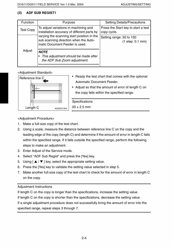
Di1611/Di2011 FIELD SERVICE Ver.1.0 Mar. 2004 ADJUSTING/SETTING
(3) ADF SUB REGIST1
<Adjustment Standard>
<Adjustment Procedure>
1. Make a full-size copy of the test chart.
2. Using a scale, measure the distance between reference line C on the copy and the
leading edge of the copy (length C) and determine if the amount of error in length C falls
within the specified range. If it falls outside the specified range, perform the following
steps to make an adjustment.
3. Enter Adjust of the Service mode.
4. Select “ADF Sub Regist” and press the [Yes] key.
5. Using [ ▲ / ▼ ] key, select the appropriate setting value.
6. Press the [Yes] key to validate the setting value selected in step 5.
7. Make another full-size copy of the test chart to check for the amount of error in length C
on the copy.
Adjustment Instructions
If length C on the copy is longer than the specifications, increase the setting value.
If length C on the copy is shorter than the specifications, decrease the setting value.
If a single adjustment procedure does not successfully bring the amount of error into the
specified range, repeat steps 3 through 7.
Function Purpose Setting Details/Precautions
Test CopyTo adjust variations in machining and installation accuracy of different parts by varying the scanning start position in the sub scanning direction when the Auto-matic Document Feeder is used.
NOTE• This adjustment should be made after
the ADF Sub Zoom adjustment.
Press the Start key to start a test copy cycle.
Adjust
Setting range: 50 to 150 (1 step: 0.1 mm)
• Ready the test chart that comes with the optional
Automatic Document Feeder.
• Adjust so that the amount of error of length C on
the copy falls within the specified range.
Specifications
20 ± 2.5 mm4035D513AALength C
Reference line C
2-4
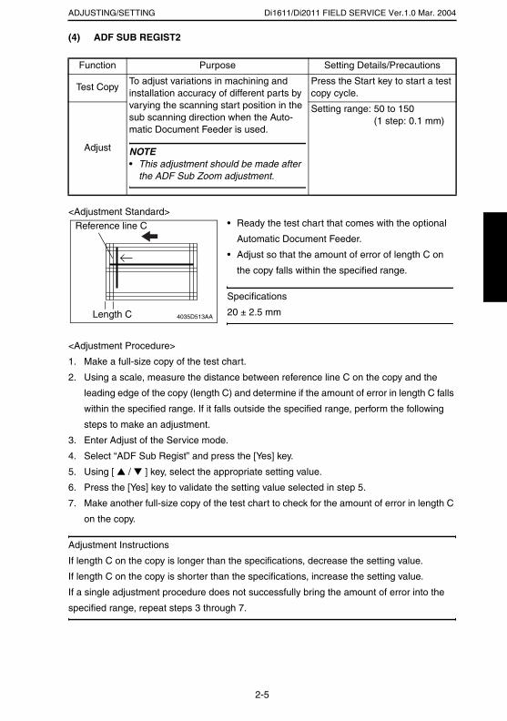
Di1611/Di2011 FIELD SERVICE Ver.1.0 Mar. 2004ADJUSTING/SETTING
(4) ADF SUB REGIST2
<Adjustment Standard>
<Adjustment Procedure>
1. Make a full-size copy of the test chart.
2. Using a scale, measure the distance between reference line C on the copy and the
leading edge of the copy (length C) and determine if the amount of error in length C falls
within the specified range. If it falls outside the specified range, perform the following
steps to make an adjustment.
3. Enter Adjust of the Service mode.
4. Select “ADF Sub Regist” and press the [Yes] key.
5. Using [ ▲ / ▼ ] key, select the appropriate setting value.
6. Press the [Yes] key to validate the setting value selected in step 5.
7. Make another full-size copy of the test chart to check for the amount of error in length C
on the copy.
Adjustment Instructions
If length C on the copy is longer than the specifications, decrease the setting value.
If length C on the copy is shorter than the specifications, increase the setting value.
If a single adjustment procedure does not successfully bring the amount of error into the
specified range, repeat steps 3 through 7.
Function Purpose Setting Details/Precautions
Test CopyTo adjust variations in machining and installation accuracy of different parts by varying the scanning start position in the sub scanning direction when the Auto-matic Document Feeder is used.
NOTE• This adjustment should be made after
the ADF Sub Zoom adjustment.
Press the Start key to start a test copy cycle.
Adjust
Setting range: 50 to 150 (1 step: 0.1 mm)
• Ready the test chart that comes with the optional
Automatic Document Feeder.
• Adjust so that the amount of error of length C on
the copy falls within the specified range.
Specifications
20 ± 2.5 mm4035D513AA
Reference line C
Length C
2-5
Di1611/Di2011 FIELD SERVICE Ver.1.0 Mar. 2004 ADJUSTING/SETTING
(5) ADF REG. LOOP1
<Adjustment Procedure>
1. Enter Adjust of the Service mode.
2. Select “ADF Reg. Loop1” and press the [Yes] key.
3. Using [ ▲ / ▼ ] key, select the desired setting value.
4. Press the [Yes] key to validate the setting value selected in step 3.
Adjustment Instructions
• Try a different setting value until there is no skew, fold, or misfeed of the original.
(6) ADF REG. LOOP2
<Adjustment Procedure>
1. Enter Adjust of the Service mode.
2. Select “ADF Reg. Loop2” and press the [Yes] key.
3. Using [ ▲ / ▼ ] key, select the desired setting value.
4. Press the [Yes] key to validate the setting value selected in step 3.
Adjustment Instructions
• Try a different setting value until there is no skew, fold, or misfeed of the original.
Purpose Setting Details/Precautions
To adjust the length of loop formed in the orig-inal before the Registration Roller.
✽ When a skew feed, fold, or misfeed of the original occurs
• The default setting is “100.” Setting range: 95 to 105
(1 step: 1.0 mm)
Purpose Setting Details/Precautions
To adjust the length of loop formed in the orig-inal before the Registration Roller.
✽ When a skew feed, fold, or misfeed of the original occurs
• The default setting is “100.” Setting range: 95 to 105
(1 step: 1.0 mm)
2-6
Di1611/Di2011 FIELD SERVICE Ver.1.0 Mar. 2004ADJUSTING/SETTING
1.2.2 FUNCTION
(1) ADF FEED TEST
(2) COPY ADF GLASS AREA
Purpose Setting Details/Precautions
• To check for correct paper passage of the paper take-up and transport system in the Automatic (Duplexing) Document Feeder alone as a single unit.
• Here are the details of operation involved in the paper passage motion.
• The Scanner does not make any scan motion.
• Paper passage operation continues until all pages of the document loaded in the unit have been fed in.
✽ When a paper misfeed of originals occurs
<Step>1. Load paper in the ADF.2. Press the Start key to start the ADF feed
test.✽ Press the Stop key to stop the ADF feed
test.
Purpose Setting Details/Precautions
To check for scratches and dirt on the Origi-nal Scanning Glass.
✽ When a dirty image occurs
<Step>1. Place a gray chart (OD = 0.3) on the
Original Glass.2. Press the Start key to start the Copy
ADF Glass Area test.3. The Scanner moves from its standby
position to a point 2 mm to the left of the Original Scanning Glass.
4. The Scanner moves to the right to start a scan motion.
5. The copier produces two copy samples (in order to know dirt on the glass from printer image noise).
2-7
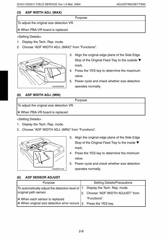
Di1611/Di2011 FIELD SERVICE Ver.1.0 Mar. 2004 ADJUSTING/SETTING
(3) ADF WIDTH ADJ. (MAX)
<Setting Details>
1. Display the Tech. Rep. mode.
2. Choose “ADF WIDTH ADJ. (MAX)” from “Functions”.
(6) ADF WIDTH ADJ. (MIN)
<Setting Details>
1. Display the Tech. Rep. mode.
2. Choose “ADF WIDTH ADJ. (MIN)” from “Functions”.
(6) ADF SENSOR ADJUST
Purpose
To adjust the original size detection VR.
✽ When PBA-VR board is replaced
Purpose
To adjust the original size detection VR.
✽ When PBA-VR board is replaced
Purpose Setting Details/Precautions
To automatically adjust the detection level of original path sensor.
✽ When each sensor is replaced✽ When original size detection error occurs
1. Display the Tech. Rep. mode.
2. Choose “ADF WIDTH ADJUST” from
“Functions”.
3. Press the YES key.
3. Align the original edge plane of the Side Edge
Stop of the Original Feed Tray to the outside ▼
mark.
4. Press the YES key to determine the maximum
value.
5. Power cycle and check whether size detection
operates normally.4344D540AA
3. Align the original edge plane of the Side Edge
Stop of the Original Feed Tray to the inside ▼
mark.
4. Press the YES key to determine the minimum
value.
5. Power cycle and check whether size detection
operates normally.4344D541AA
2-8
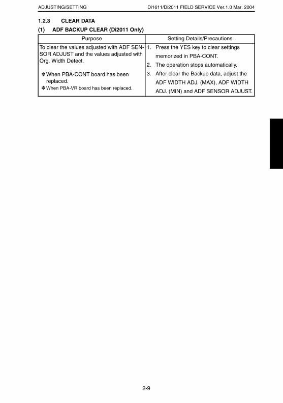
Di1611/Di2011 FIELD SERVICE Ver.1.0 Mar. 2004ADJUSTING/SETTING
1.2.3 CLEAR DATA
(1) ADF BACKUP CLEAR (Di2011 Only)
Purpose Setting Details/Precautions
To clear the values adjusted with ADF SEN-SOR ADJUST and the values adjusted with Org. Width Detect.
✽ When PBA-CONT board has been replaced.
✽ When PBA-VR board has been replaced.
1. Press the YES key to clear settings
memorized in PBA-CONT.
2. The operation stops automatically.
3. After clear the Backup data, adjust the
ADF WIDTH ADJ. (MAX), ADF WIDTH
ADJ. (MIN) and ADF SENSOR ADJUST.
2-9

Di1611/Di2011 FIELD SERVICE Ver.1.0 Mar. 2004 ADJUSTING/SETTING
2. MECHANICAL ADJUSTMENTS2.1 Checking for Skew Feed
1. Test chart (A3) of the attachment is prepared.
* Copy Paper Inch area: 11 × 17 Metric area: A3
2. Plug in the power cord and turn ON the Power
Switch of the copier.
4688U042AB
20 mm
3. Load the test chart in the Automatic Document
Feeder and make one 1-sided copy five consecu-
tive times.
4344U046AB
4. Fold each of the sample copies as illustrated and
check for any deviation.
Specifications: 0 ± 3.0 mm
* If the deviation does not fall within the specified range, perform the following adjustment procedure.
4688U001AB
2-10
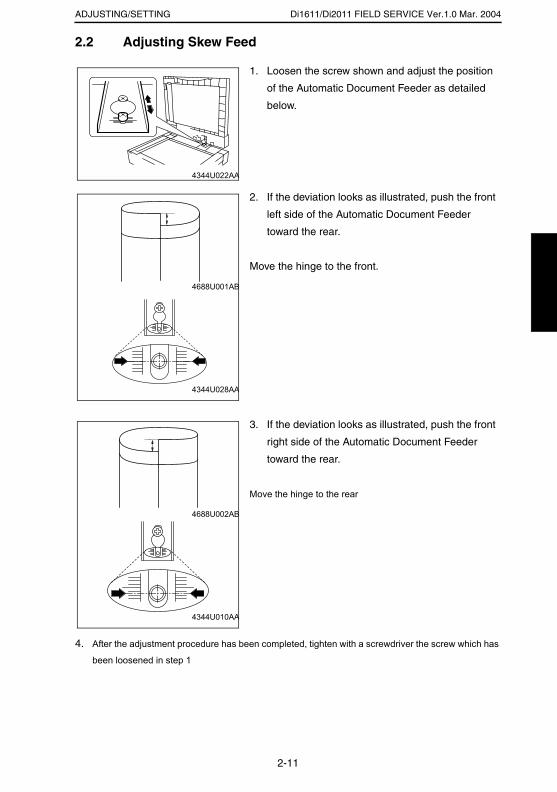
Di1611/Di2011 FIELD SERVICE Ver.1.0 Mar. 2004ADJUSTING/SETTING
2.2 Adjusting Skew Feed
4. After the adjustment procedure has been completed, tighten with a screwdriver the screw which has
been loosened in step 1
1. Loosen the screw shown and adjust the position
of the Automatic Document Feeder as detailed
below.
4344U022AA
2. If the deviation looks as illustrated, push the front
left side of the Automatic Document Feeder
toward the rear.
Move the hinge to the front.
4688U001AB
4344U028AA
3. If the deviation looks as illustrated, push the front
right side of the Automatic Document Feeder
toward the rear.
Move the hinge to the rear
4688U002AB
4344U010AA
2-11
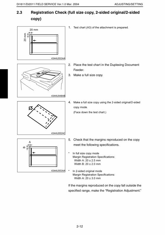
Di1611/Di2011 FIELD SERVICE Ver.1.0 Mar. 2004 ADJUSTING/SETTING
2.3 Registration Check (full size copy, 2-sided original/2-sided
copy)
1. Test chart (A3) of the attachment is prepared.
4344U053AA
20 mm
20 m
m
2. Place the test chart in the Duplexing Document
Feeder.
3. Make a full size copy.
4344U048AB
4. Make a full size copy using the 2-sided original/2-sided
copy mode.
(Face down the test chart.)
4344U052AC
5. Check that the margins reproduced on the copy
meet the following specifications.
* In full size copy modeMargin Registration Specifications: Width A: 20 ± 2.5 mm Width B: 20 ± 2.0 mm
* In 2-sided original mode Margin Registration Specifications: Width A: 20 ± 3.0 mm
If the margins reproduced on the copy fall outside the
specified range, make the “Registration Adjustment.”
4344U053AA
A
B
2-12

TROUBLESHOOTING
19971
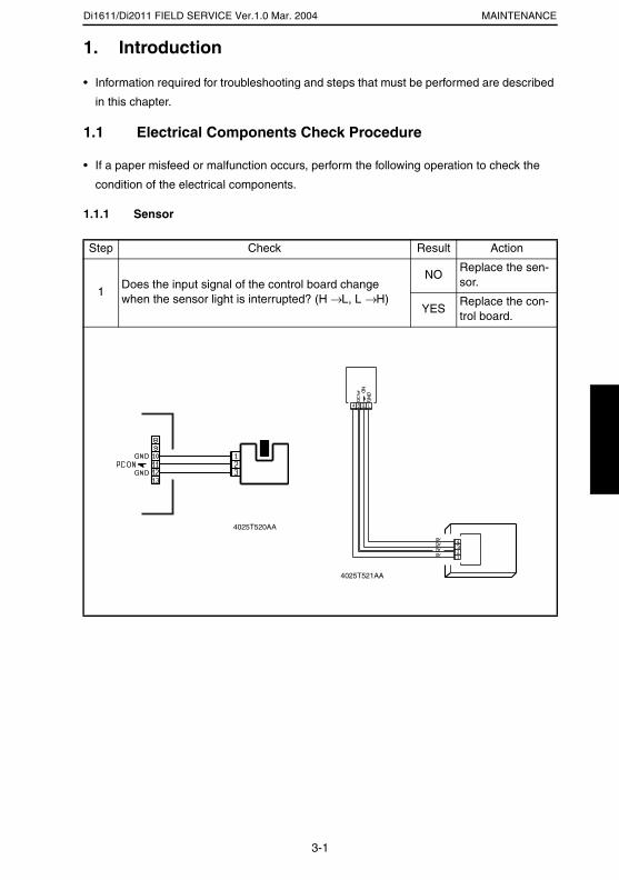
Di1611/Di2011 FIELD SERVICE Ver.1.0 Mar. 2004 MAINTENANCE
1. Introduction
• Information required for troubleshooting and steps that must be performed are described
in this chapter.
1.1 Electrical Components Check Procedure
• If a paper misfeed or malfunction occurs, perform the following operation to check the
condition of the electrical components.
1.1.1 Sensor
Step Check Result Action
1Does the input signal of the control board change when the sensor light is interrupted? (H → L, L → H)
NOReplace the sen-sor.
YESReplace the con-trol board.
4025T520AA
4025T521AA
3-1
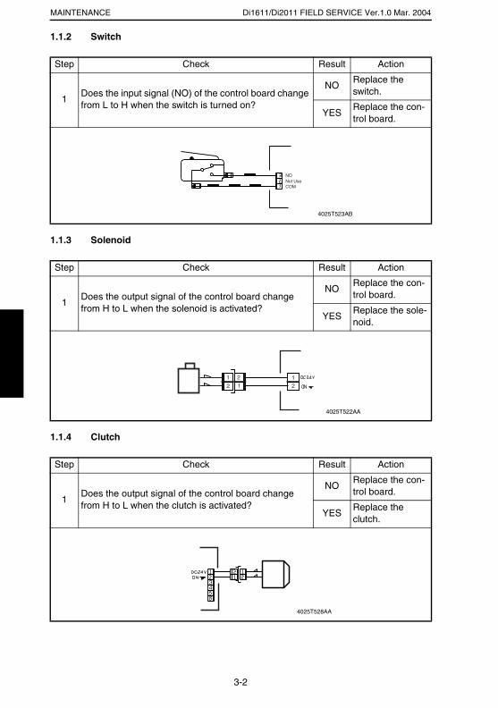
Di1611/Di2011 FIELD SERVICE Ver.1.0 Mar. 2004MAINTENANCE
1.1.2 Switch
1.1.3 Solenoid
1.1.4 Clutch
Step Check Result Action
1Does the input signal (NO) of the control board change from L to H when the switch is turned on?
NOReplace the switch.
YESReplace the con-trol board.
Step Check Result Action
1Does the output signal of the control board change from H to L when the solenoid is activated?
NOReplace the con-trol board.
YESReplace the sole-noid.
Step Check Result Action
1Does the output signal of the control board change from H to L when the clutch is activated?
NOReplace the con-trol board.
YESReplace the clutch.
Not UseCOM
NO
4025T523AB
12
212
1
4025T522AA
4025T528AA
3-2

Di1611/Di2011 FIELD SERVICE Ver.1.0 Mar. 2004 MAINTENANCE
1.1.5 Motor
Step Check Result Action
1Does the LOCK signal of the control board switch to H when the machine goes into standby?
NOReplace the con-trol board.Replace the motor.
2Does the REM signal of the control board change from H to L when the motor is turned on?
YES Replace the motor.
NOReplace the con-trol board.
Step Check Result Action
1
Does the input signal of the control board change from H to L when the motor is turned on?(Input signals differ according to the direction of rota-tion)
YESReplace the motor.
NOReplace the con-trol board.
Step Check Result Action
1Are the relay connector of the motor and the print jack of the control board correctly connected?
YESReplace the motor or the con-trol board.
NOConnect the con-nector or the print jack.
4025T526AA
GND
REM
LOCK
2
1
3
4025T525AA
4025T527AA
3-3
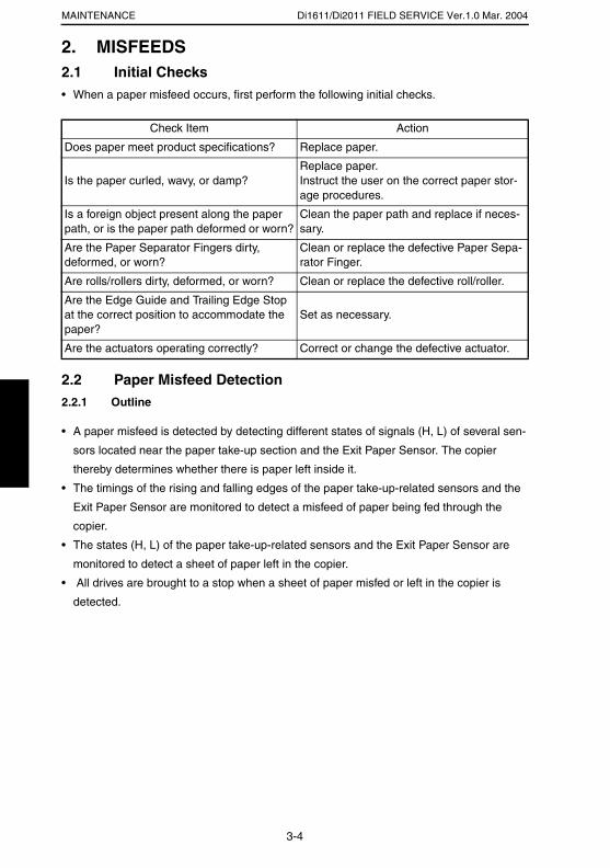
Di1611/Di2011 FIELD SERVICE Ver.1.0 Mar. 2004MAINTENANCE
2. MISFEEDS2.1 Initial Checks• When a paper misfeed occurs, first perform the following initial checks.
2.2 Paper Misfeed Detection2.2.1 Outline
• A paper misfeed is detected by detecting different states of signals (H, L) of several sen-
sors located near the paper take-up section and the Exit Paper Sensor. The copier
thereby determines whether there is paper left inside it.
• The timings of the rising and falling edges of the paper take-up-related sensors and the
Exit Paper Sensor are monitored to detect a misfeed of paper being fed through the
copier.
• The states (H, L) of the paper take-up-related sensors and the Exit Paper Sensor are
monitored to detect a sheet of paper left in the copier.
• All drives are brought to a stop when a sheet of paper misfed or left in the copier is
detected.
Check Item Action
Does paper meet product specifications? Replace paper.
Is the paper curled, wavy, or damp?Replace paper.Instruct the user on the correct paper stor-age procedures.
Is a foreign object present along the paper path, or is the paper path deformed or worn?
Clean the paper path and replace if neces-sary.
Are the Paper Separator Fingers dirty, deformed, or worn?
Clean or replace the defective Paper Sepa-rator Finger.
Are rolls/rollers dirty, deformed, or worn? Clean or replace the defective roll/roller.
Are the Edge Guide and Trailing Edge Stop at the correct position to accommodate the paper?
Set as necessary.
Are the actuators operating correctly? Correct or change the defective actuator.
3-4
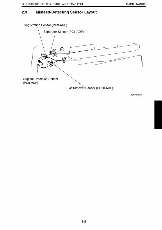
Di1611/Di2011 FIELD SERVICE Ver.1.0 Mar. 2004 MAINTENANCE
2.3 Misfeed-Detecting Sensor Layout
4344T502AA
Separator Sensor (PC6-ADF)
Registration Sensor (PC9-ADF)
Original Detection Sensor (PC8-ADF)
Exit/Turnover Sensor (PC10-ADF)
3-5
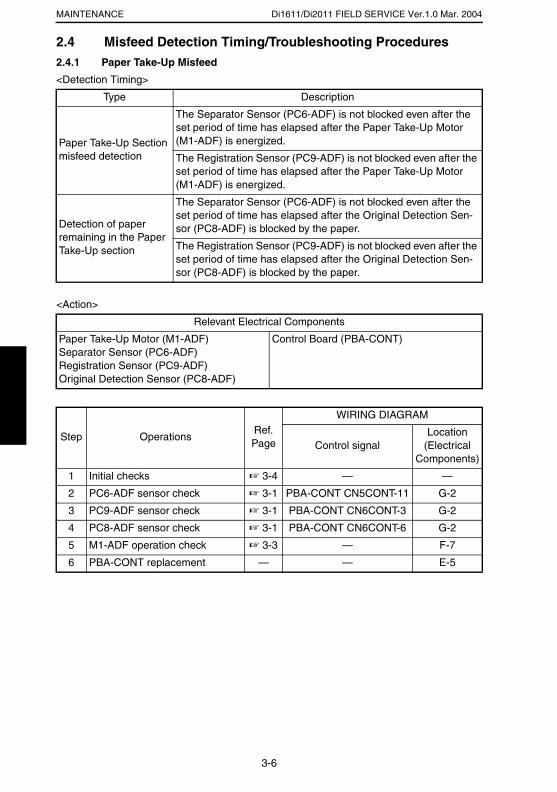
Di1611/Di2011 FIELD SERVICE Ver.1.0 Mar. 2004MAINTENANCE
2.4 Misfeed Detection Timing/Troubleshooting Procedures2.4.1 Paper Take-Up Misfeed
<Detection Timing>
<Action>
Type Description
Paper Take-Up Section misfeed detection
The Separator Sensor (PC6-ADF) is not blocked even after the set period of time has elapsed after the Paper Take-Up Motor (M1-ADF) is energized.
The Registration Sensor (PC9-ADF) is not blocked even after the set period of time has elapsed after the Paper Take-Up Motor (M1-ADF) is energized.
Detection of paper remaining in the Paper Take-Up section
The Separator Sensor (PC6-ADF) is not blocked even after the set period of time has elapsed after the Original Detection Sen-sor (PC8-ADF) is blocked by the paper.
The Registration Sensor (PC9-ADF) is not blocked even after the set period of time has elapsed after the Original Detection Sen-sor (PC8-ADF) is blocked by the paper.
Relevant Electrical Components
Paper Take-Up Motor (M1-ADF)Separator Sensor (PC6-ADF)Registration Sensor (PC9-ADF)Original Detection Sensor (PC8-ADF)
Control Board (PBA-CONT)
Step OperationsRef. Page
WIRING DIAGRAM
Control signalLocation
(Electrical Components)
1 Initial checks ☞ 3-4 — —
2 PC6-ADF sensor check ☞ 3-1 PBA-CONT CN5CONT-11 G-2
3 PC9-ADF sensor check ☞ 3-1 PBA-CONT CN6CONT-3 G-2
4 PC8-ADF sensor check ☞ 3-1 PBA-CONT CN6CONT-6 G-2
5 M1-ADF operation check ☞ 3-3 — F-7
6 PBA-CONT replacement — — E-5
3-6
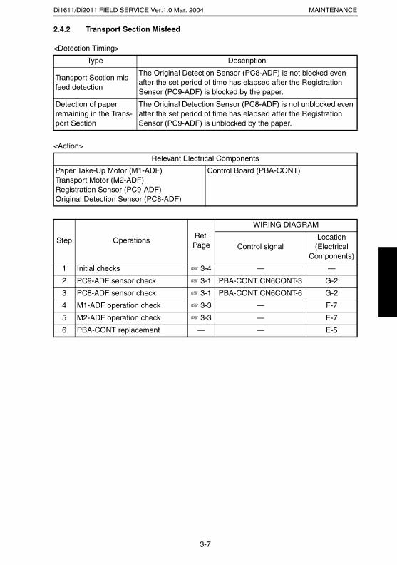
Di1611/Di2011 FIELD SERVICE Ver.1.0 Mar. 2004 MAINTENANCE
2.4.2 Transport Section Misfeed
<Detection Timing>
<Action>
Type Description
Transport Section mis-feed detection
The Original Detection Sensor (PC8-ADF) is not blocked even after the set period of time has elapsed after the Registration Sensor (PC9-ADF) is blocked by the paper.
Detection of paper remaining in the Trans-port Section
The Original Detection Sensor (PC8-ADF) is not unblocked even after the set period of time has elapsed after the Registration Sensor (PC9-ADF) is unblocked by the paper.
Relevant Electrical Components
Paper Take-Up Motor (M1-ADF)Transport Motor (M2-ADF)Registration Sensor (PC9-ADF)Original Detection Sensor (PC8-ADF)
Control Board (PBA-CONT)
Step OperationsRef. Page
WIRING DIAGRAM
Control signalLocation
(Electrical Components)
1 Initial checks ☞ 3-4 — —
2 PC9-ADF sensor check ☞ 3-1 PBA-CONT CN6CONT-3 G-2
3 PC8-ADF sensor check ☞ 3-1 PBA-CONT CN6CONT-6 G-2
4 M1-ADF operation check ☞ 3-3 — F-7
5 M2-ADF operation check ☞ 3-3 — E-7
6 PBA-CONT replacement — — E-5
3-7
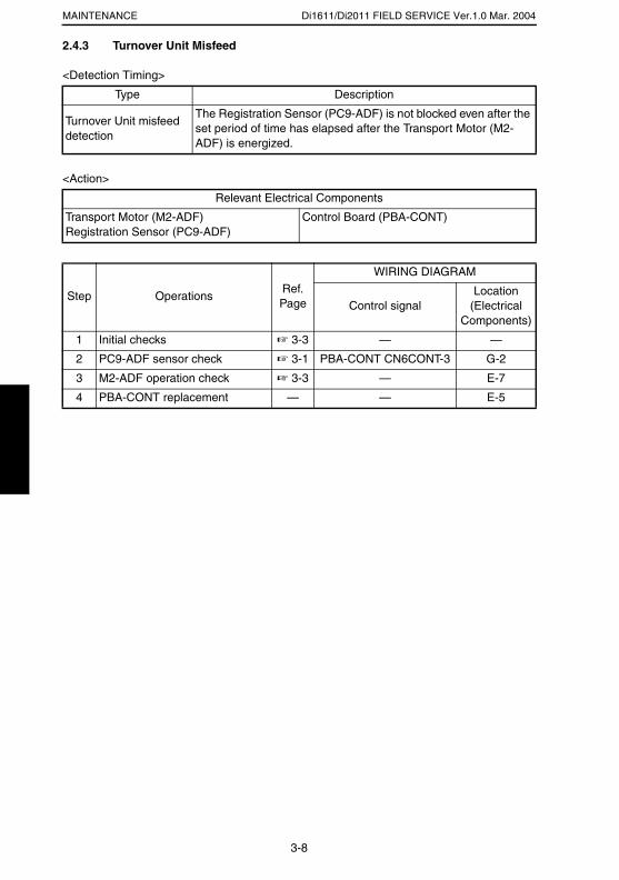
Di1611/Di2011 FIELD SERVICE Ver.1.0 Mar. 2004MAINTENANCE
2.4.3 Turnover Unit Misfeed
<Detection Timing>
<Action>
Type Description
Turnover Unit misfeed detection
The Registration Sensor (PC9-ADF) is not blocked even after the set period of time has elapsed after the Transport Motor (M2-ADF) is energized.
Relevant Electrical Components
Transport Motor (M2-ADF)Registration Sensor (PC9-ADF)
Control Board (PBA-CONT)
Step OperationsRef. Page
WIRING DIAGRAM
Control signalLocation
(Electrical Components)
1 Initial checks ☞ 3-3 — —
2 PC9-ADF sensor check ☞ 3-1 PBA-CONT CN6CONT-3 G-2
3 M2-ADF operation check ☞ 3-3 — E-7
4 PBA-CONT replacement — — E-5
3-8
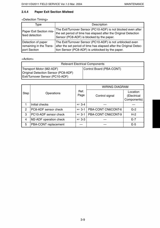
Di1611/Di2011 FIELD SERVICE Ver.1.0 Mar. 2004 MAINTENANCE
2.4.4 Paper Exit Section Misfeed
<Detection Timing>
<Action>
Type Description
Paper Exit Section mis-feed detection
The Exit/Turnover Sensor (PC10-ADF) is not blocked even after the set period of time has elapsed after the Original Detection Sensor (PC8-ADF) is blocked by the paper.
Detection of paper remaining in the Trans-port Section
The Exit/Turnover Sensor (PC10-ADF) is not unblocked even after the set period of time has elapsed after the Original Detec-tion Sensor (PC8-ADF) is unblocked by the paper.
Relevant Electrical Components
Transport Motor (M2-ADF)Original Detection Sensor (PC8-ADF)Exit/Turnover Sensor (PC10-ADF)
Control Board (PBA-CONT)
Step OperationsRef. Page
WIRING DIAGRAM
Control signalLocation
(Electrical Components)
1 Initial checks ☞ 3-4 — —
2 PC8-ADF sensor check ☞ 3-1 PBA-CONT CN6CONT-6 G-2
3 PC10-ADF sensor check ☞ 3-1 PBA-CONT CN6CONT-9 H-2
4 M2-ADF operation check ☞ 3-3 — E-7
5 PBA-CONT replacement — — E-5
3-9
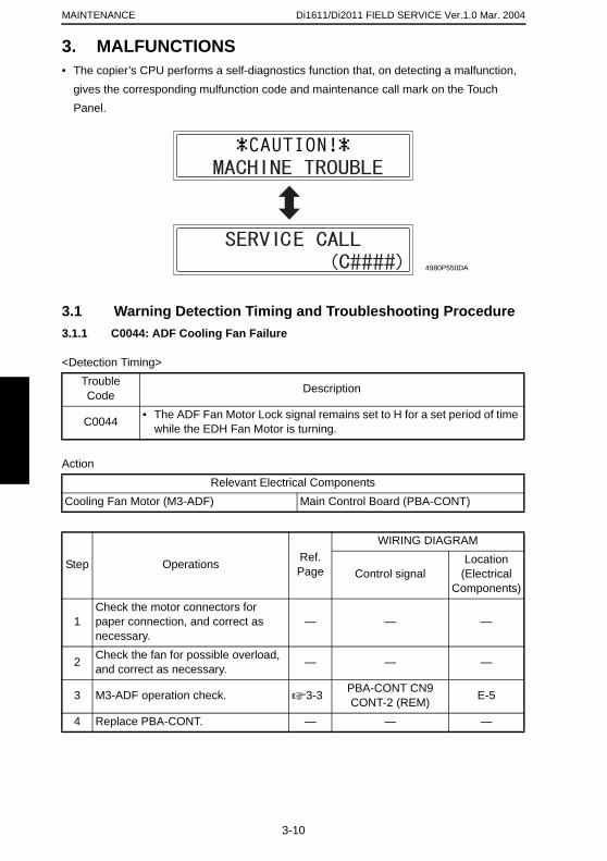
MAINTENANCE
3. MALFUNC• The copier’s CPU pe
gives the correspondPanel.
3.1 Warning 3.1.1 C0044: ADF
<Detection Timing>
Action
TroubleCode
C0044 • The while
Cooling Fan Motor (M
Step Op
1Check the motopaper connectionecessary.
2 Check the fan foand correct as n
3 M3-ADF operati
4 Replace PBA-C
Di1611/Di2011 FIELD SERVICE Ver.1.0 Mar. 2004
TIONSrforms a self-diagnostics function that, on detecting a malfunction, ing mulfunction code and maintenance call mark on the Touch
Detection Timing and Troubleshooting Procedure Cooling Fan Failure
Description
ADF Fan Motor Lock signal remains set to H for a set period of time the EDH Fan Motor is turning.
Relevant Electrical Components3-ADF) Main Control Board (PBA-CONT)
erations Ref. Page
WIRING DIAGRAM
Control signalLocation
(Electrical Components)
r connectors for n, and correct as — — —
4980P550DA
3-10
r possible overload, ecessary. — — —
on check. ☞ 3-3 PBA-CONT CN9 CONT-2 (REM) E-5
ONT. — — —
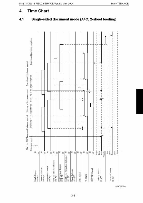
Di1611/Di2011 FIELD SERVICE Ver.1.0 Mar. 2004 MAINTENANCE
4. Time Chart
4.1 Single-sided document mode (A4C; 2-sheet feeding)
4030T505CA
3-11
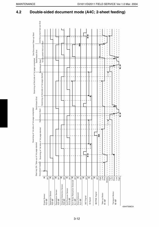
Di1611/Di2011 FIELD SERVICE Ver.1.0 Mar. 2004MAINTENANCE
4.2 Double-sided document mode (A4C; 2-sheet feeding)
4344T506CA
3-12
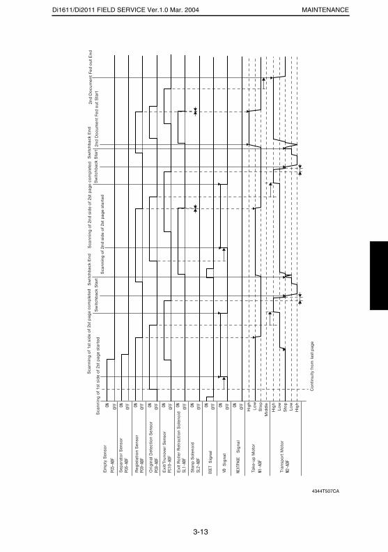
Di1611/Di2011 FIELD SERVICE Ver.1.0 Mar. 2004 MAINTENANCE
4344T507CA
3-13
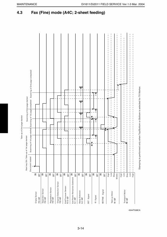
Di1611/Di2011 FIELD SERVICE Ver.1.0 Mar. 2004MAINTENANCE
4.3 Fax (Fine) mode (A4C; 2-sheet feeding)
4344T508CA
3-14
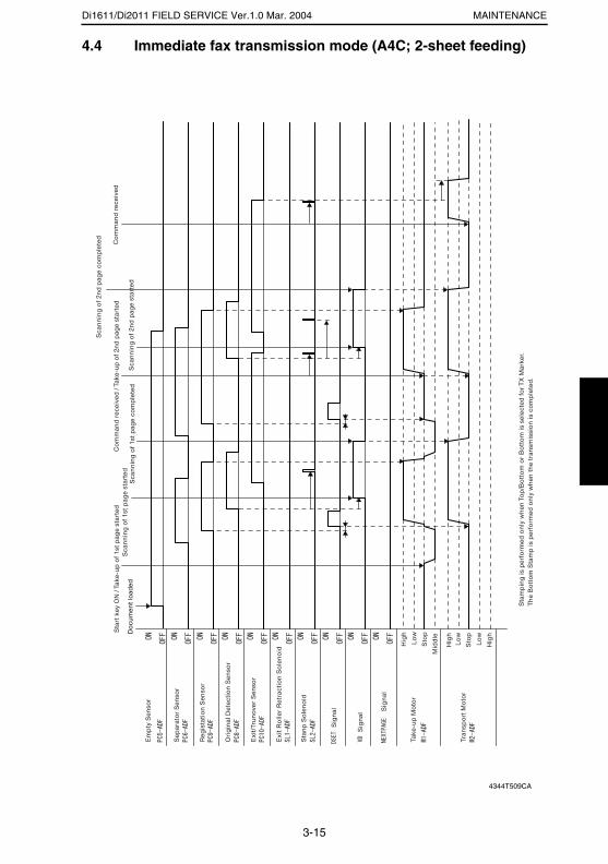
Di1611/Di2011 FIELD SERVICE Ver.1.0 Mar. 2004 MAINTENANCE
4.4 Immediate fax transmission mode (A4C; 2-sheet feeding)
4344T509CA
3-15

SERVICE MANUAL
2004.3Ver. 1.0
FIELD SERVICE
AD-17
INDEX
ADJUSTMENT/SETTING
MAINTENANCE
TROUBLESHOOTING
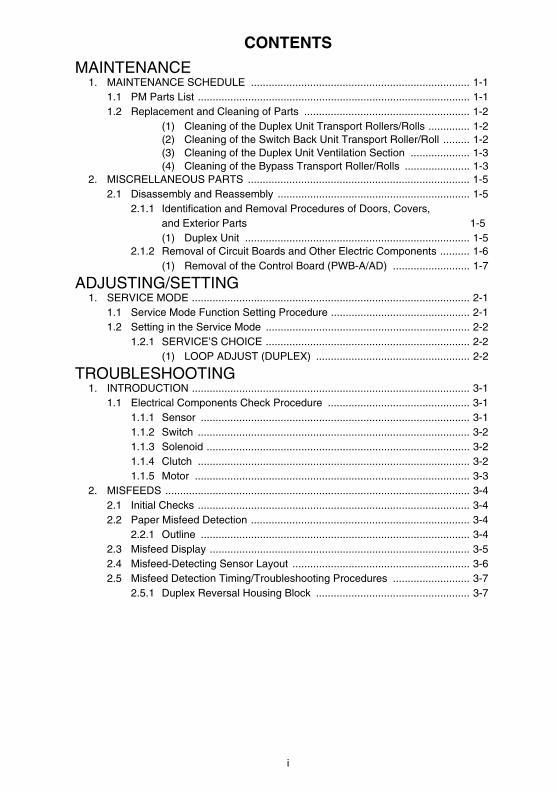
i
CONTENTS
MAINTENANCE1. MAINTENANCE SCHEDULE .......................................................................... 1-1
1.1 PM Parts List ............................................................................................ 1-11.2 Replacement and Cleaning of Parts ........................................................ 1-2
(1) Cleaning of the Duplex Unit Transport Rollers/Rolls .............. 1-2(2) Cleaning of the Switch Back Unit Transport Roller/Roll ......... 1-2(3) Cleaning of the Duplex Unit Ventilation Section .................... 1-3(4) Cleaning of the Bypass Transport Roller/Rolls ...................... 1-3
2. MISCRELLANEOUS PARTS ........................................................................... 1-52.1 Disassembly and Reassembly ................................................................. 1-5
2.1.1 Identification and Removal Procedures of Doors, Covers, and Exterior Parts 1-5(1) Duplex Unit ............................................................................ 1-5
2.1.2 Removal of Circuit Boards and Other Electric Components .......... 1-6(1) Removal of the Control Board (PWB-A/AD) .......................... 1-7
ADJUSTING/SETTING1. SERVICE MODE .............................................................................................. 2-1
1.1 Service Mode Function Setting Procedure ............................................... 2-11.2 Setting in the Service Mode ..................................................................... 2-2
1.2.1 SERVICE’S CHOICE ..................................................................... 2-2(1) LOOP ADJUST (DUPLEX) .................................................... 2-2
TROUBLESHOOTING1. INTRODUCTION .............................................................................................. 3-1
1.1 Electrical Components Check Procedure ................................................ 3-11.1.1 Sensor ........................................................................................... 3-11.1.2 Switch ............................................................................................ 3-21.1.3 Solenoid ......................................................................................... 3-21.1.4 Clutch ............................................................................................ 3-21.1.5 Motor ............................................................................................. 3-3
2. MISFEEDS ....................................................................................................... 3-42.1 Initial Checks ............................................................................................ 3-42.2 Paper Misfeed Detection .......................................................................... 3-4
2.2.1 Outline ........................................................................................... 3-42.3 Misfeed Display ........................................................................................ 3-52.4 Misfeed-Detecting Sensor Layout ............................................................ 3-62.5 Misfeed Detection Timing/Troubleshooting Procedures .......................... 3-7
2.5.1 Duplex Reversal Housing Block .................................................... 3-7

MAINTENANCE
19971
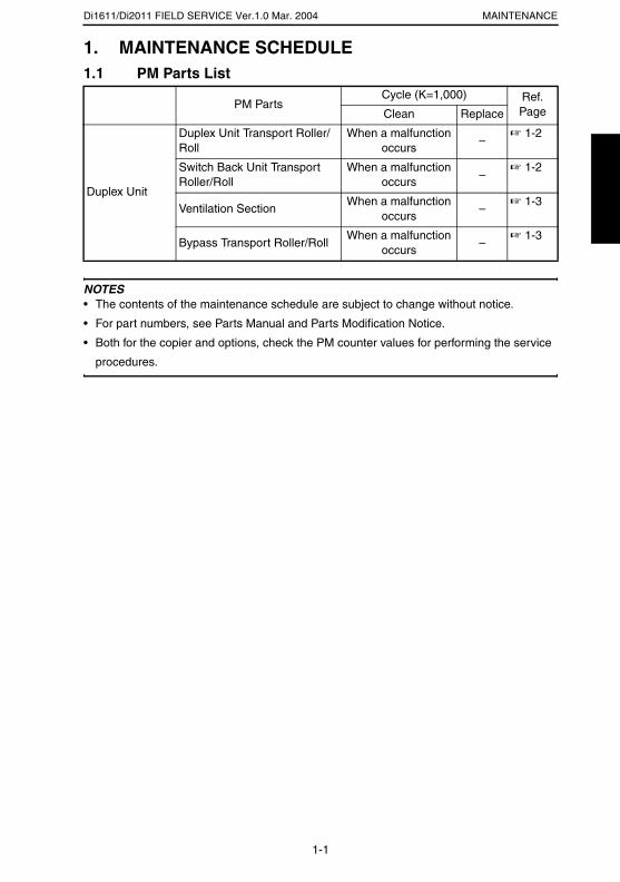
Di1611/Di2011 FIELD SERVICE Ver.1.0 Mar. 2004 MAINTENANCE
1. MAINTENANCE SCHEDULE1.1 PM Parts List
NOTES• The contents of the maintenance schedule are subject to change without notice.
• For part numbers, see Parts Manual and Parts Modification Notice.
• Both for the copier and options, check the PM counter values for performing the service
procedures.
PM PartsCycle (K=1,000) Ref.
PageClean Replace
Duplex Unit
Duplex Unit Transport Roller/Roll
When a malfunction occurs
–☞ 1-2
Switch Back Unit Transport Roller/Roll
When a malfunction occurs
–☞ 1-2
Ventilation SectionWhen a malfunction
occurs–
☞ 1-3
Bypass Transport Roller/RollWhen a malfunction
occurs–
☞ 1-3
1-1
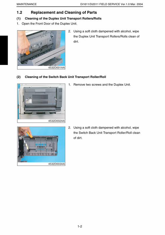
Di1611/Di2011 FIELD SERVICE Ver.1.0 Mar. 2004MAINTENANCE
1.2 Replacement and Cleaning of Parts(1) Cleaning of the Duplex Unit Transport Rollers/Rolls
1. Open the Front Door of the Duplex Unit.
(2) Cleaning of the Switch Back Unit Transport Roller/Roll
2. Using a soft cloth dampened with alcohol, wipe
the Duplex Unit Transport Rollers/Rolls clean of
dirt.
4532D001AA
1. Remove two screws and the Duplex Unit.
4532D002AA
2. Using a soft cloth dampened with alcohol, wipe
the Switch Back Unit Transport Roller/Roll clean
of dirt.
4532D003AA
1-2
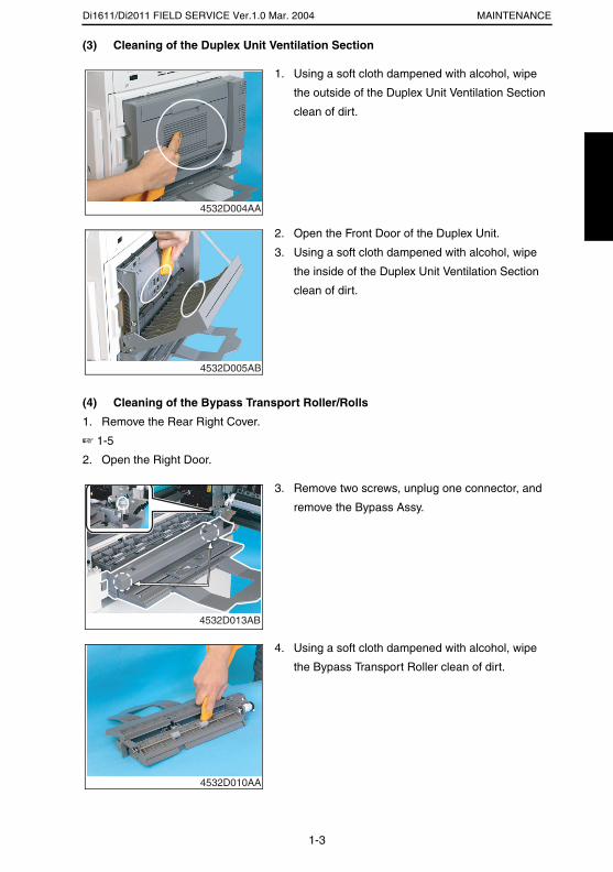
Di1611/Di2011 FIELD SERVICE Ver.1.0 Mar. 2004 MAINTENANCE
(3) Cleaning of the Duplex Unit Ventilation Section
(4) Cleaning of the Bypass Transport Roller/Rolls
1. Remove the Rear Right Cover.
☞ 1-5
2. Open the Right Door.
1. Using a soft cloth dampened with alcohol, wipe
the outside of the Duplex Unit Ventilation Section
clean of dirt.
4532D004AA
2. Open the Front Door of the Duplex Unit.
3. Using a soft cloth dampened with alcohol, wipe
the inside of the Duplex Unit Ventilation Section
clean of dirt.
4532D005AB
3. Remove two screws, unplug one connector, and
remove the Bypass Assy.
4532D013AB
4. Using a soft cloth dampened with alcohol, wipe
the Bypass Transport Roller clean of dirt.
4532D010AA
1-3

Di1611/Di2011 FIELD SERVICE Ver.1.0 Mar. 2004MAINTENANCE
5. Using a soft cloth dampened with alcohol, wipe
the Bypass Transport Rolls clean of dirt.
4532D015AA
1-4
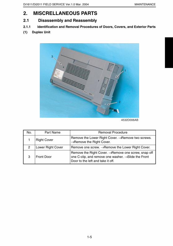
Di1611/Di2011 FIELD SERVICE Ver.1.0 Mar. 2004 MAINTENANCE
2. MISCRELLANEOUS PARTS2.1 Disassembly and Reassembly2.1.1 Identification and Removal Procedures of Doors, Covers, and Exterior Parts
(1) Duplex Unit
No. Part Name Removal Procedure
1 Right CoverRemove the Lower Right Cover. → Remove two screws. → Remove the Right Cover.
2 Lower Right Cover Remove one screw. → Remove the Lower Right Cover.
3 Front DoorRemove the Right Cover. → Remove one screw, snap off one C-clip, and remove one washer. → Slide the Front Door to the left and take it off.
4532D006AB
1
2
3
1-5
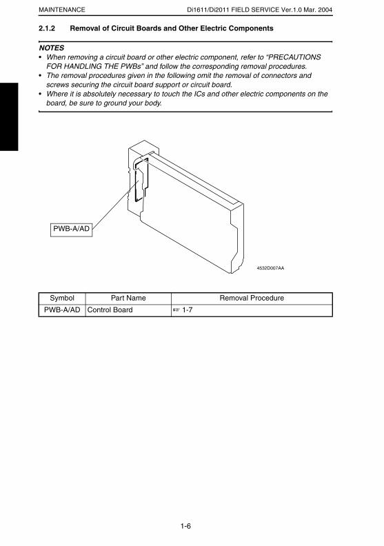
Di1611/Di2011 FIELD SERVICE Ver.1.0 Mar. 2004MAINTENANCE
2.1.2 Removal of Circuit Boards and Other Electric Components
NOTES• When removing a circuit board or other electric component, refer to “PRECAUTIONS
FOR HANDLING THE PWBs” and follow the corresponding removal procedures.• The removal procedures given in the following omit the removal of connectors and
screws securing the circuit board support or circuit board.• Where it is absolutely necessary to touch the ICs and other electric components on the
board, be sure to ground your body.
Symbol Part Name Removal Procedure
PWB-A/AD Control Board ☞ 1-7
PWB-A/AD
4532D007AA
1-6
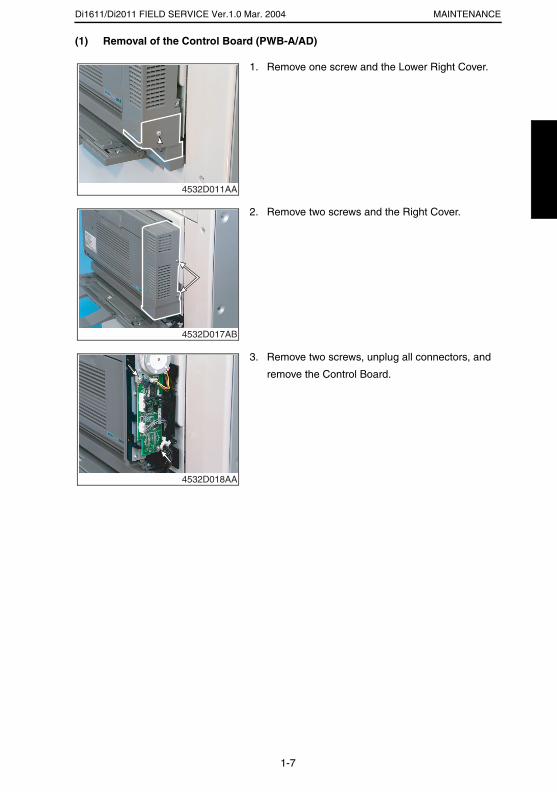
Di1611/Di2011 FIELD SERVICE Ver.1.0 Mar. 2004 MAINTENANCE
(1) Removal of the Control Board (PWB-A/AD)
1. Remove one screw and the Lower Right Cover.
4532D011AA
2. Remove two screws and the Right Cover.
4532D017AB
3. Remove two screws, unplug all connectors, and
remove the Control Board.
4532D018AA
1-7

ADJUSTING/SETTING
19971

Di1611/Di2011 FIELD SERVICE Ver.1.0 Mar. 2004ADJUSTING/SETTING
1. SERVICE MODE1.1 Service Mode Function Setting Procedure
NOTE• Care must be used to ensure that only the personnel who are involved in service jobs
know the procedure to enter the Service mode.
<Procedure>
1. Press the Utility key.
2. Press the following keys in this order.
3. Stop → 0 → 0 → Stop → 0 → 1
4. The Service mode menu screen will appear.
<Exiting the Mode>
• Press the Panel Reset key as many times as it is required to display the initial screen.
<Service Mode Function Setting Value Changing Procedure>
1. Select the desired item using [ ▲ / ▼ ] key.
2. Select the setting value using [ ▲ / ▼ ] key, [ < / > ] key, or the 10-Key Pad.
3. Validate the selection by pressing the [Yes] key.
4. To go back to previous screen, press the [No] key.
2-1
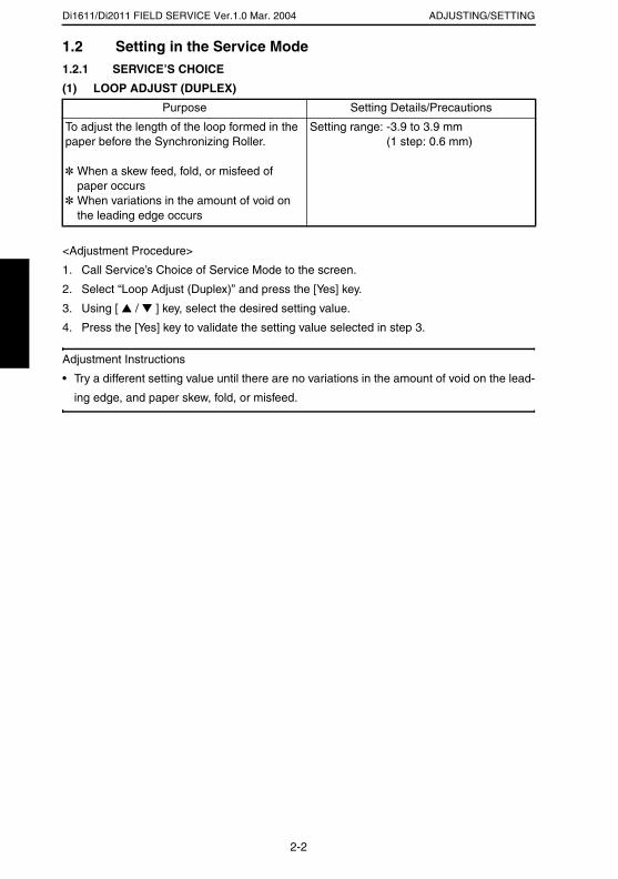
Di1611/Di2011 FIELD SERVICE Ver.1.0 Mar. 2004 ADJUSTING/SETTING
1.2 Setting in the Service Mode1.2.1 SERVICE’S CHOICE
(1) LOOP ADJUST (DUPLEX)
<Adjustment Procedure>
1. Call Service’s Choice of Service Mode to the screen.
2. Select “Loop Adjust (Duplex)” and press the [Yes] key.
3. Using [ ▲ / ▼ ] key, select the desired setting value.
4. Press the [Yes] key to validate the setting value selected in step 3.
Adjustment Instructions
• Try a different setting value until there are no variations in the amount of void on the lead-
ing edge, and paper skew, fold, or misfeed.
Purpose Setting Details/Precautions
To adjust the length of the loop formed in the paper before the Synchronizing Roller.
✽ When a skew feed, fold, or misfeed of paper occurs
✽ When variations in the amount of void on the leading edge occurs
Setting range: -3.9 to 3.9 mm (1 step: 0.6 mm)
2-2

TROUBLESHOOTING
19971

Di1611/Di2011 FIELD SERVICE Ver.1.0 Mar. 2004 TROUBLESHOOTING
1. INTRODUCTION
• Information required for troubleshooting and steps that must be performed are described
in this chapter.
1.1 Electrical Components Check Procedure• If a paper misfeed or malfunction occurs, perform the following operations to check the
condition of the electrical components.
1.1.1 Sensor
Step Check Result Action
1 Does the input signal of the control board change when the sensor light is interrupted? (H → L, L → H)
NO Replace the sensor.
YES Replace the control board.
4025T520AA
4025T521AA
3-1
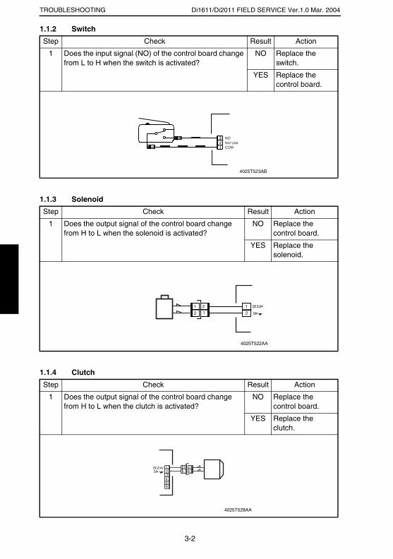
Di1611/Di2011 FIELD SERVICE Ver.1.0 Mar. 2004TROUBLESHOOTING
1.1.2 Switch
1.1.3 Solenoid
1.1.4 Clutch
Step Check Result Action
1 Does the input signal (NO) of the control board change from L to H when the switch is activated?
NO Replace the switch.
YES Replace the control board.
Step Check Result Action
1 Does the output signal of the control board change from H to L when the solenoid is activated?
NO Replace the control board.
YES Replace the solenoid.
Step Check Result Action
1 Does the output signal of the control board change from H to L when the clutch is activated?
NO Replace the control board.
YES Replace the clutch.
Not UseCOM
NO
4025T523AB
12
212
1
4025T522AA
4025T528AA
3-2
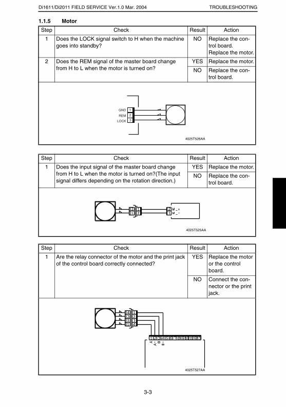
Di1611/Di2011 FIELD SERVICE Ver.1.0 Mar. 2004 TROUBLESHOOTING
1.1.5 Motor
Step Check Result Action
1 Does the LOCK signal switch to H when the machine goes into standby?
NO Replace the con-trol board. Replace the motor.
2 Does the REM signal of the master board change from H to L when the motor is turned on?
YES Replace the motor.
NO Replace the con-trol board.
Step Check Result Action
1 Does the input signal of the master board change from H to L when the motor is turned on?(The input signal differs depending on the rotation direction.)
YES Replace the motor.
NO Replace the con-trol board.
Step Check Result Action
1 Are the relay connector of the motor and the print jack of the control board correctly connected?
YES Replace the motor or the control board.
NO Connect the con-nector or the print jack.
GND
REM
LOCK
2
1
3
4025T526AA
4025T525AA
4025T527AA
3-3

Di1611/Di2011 FIELD SERVICE Ver.1.0 Mar. 2004TROUBLESHOOTING
2. MISFEEDS2.1 Initial Checks• When a paper misfeed occurs, first perform the following initial checks.
2.2 Paper Misfeed Detection2.2.1 Outline
• A paper misfeed is detected by detecting different states of signals (H, L) of several sen-
sors located near the paper take-up section and the Exit Paper Sensor. The copier
thereby determines whether there is paper left inside it.
• The timings of the rising and falling edges of the paper take-up-related sensors and the
Exit Paper Sensor are monitored to detect a misfeed of paper being fed through the
copier.
• The states (H, L) of the paper take-up-related sensors and the Exit Paper Sensor are
monitored to detect a sheet of paper left in the copier.
• All drives are brought to a stop when a sheet of paper misfed or left in the copier is
detected.
Check Item Action
Does paper meet product specifications? Replace paper.
Is the paper curled, wavy, or damp? Replace paper.Instruct the user on the correct paper storage procedures.
Is a foreign object present along the paper path, or is the paper path deformed or worn?
Clean or change the paper path.
Are the Paper Separator Fingers dirty, deformed, or worn?
Clean or replace the defective Paper Separator Finger.
Are rolls/rollers dirty, deformed, or worn? Clean or replace the defective roll/roller.
Are the Edge Guide and Trailing Edge Stop at the correct position to accommodate the paper?
Set as necessary.
Are the actuators operational and checked for correct operation?
Correct or replace the defective actua-tor.
3-4
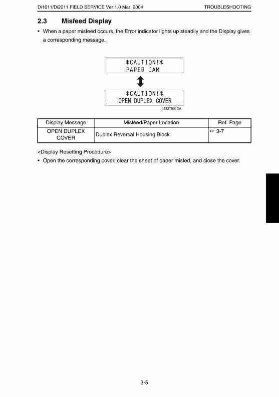
Di1611/Di2011 FIELD SERVICE Ver.1.0 Mar. 2004 TROUBLESHOOTING
2.3 Misfeed Display• When a paper misfeed occurs, the Error indicator lights up steadily and the Display gives
a corresponding message.
<Display Resetting Procedure>
• Open the corresponding cover, clear the sheet of paper misfed, and close the cover.
Display Message Misfeed/Paper Location Ref. Page
OPEN DUPLEX COVER
Duplex Reversal Housing Block☞ 3-7
4532T501CA
3-5
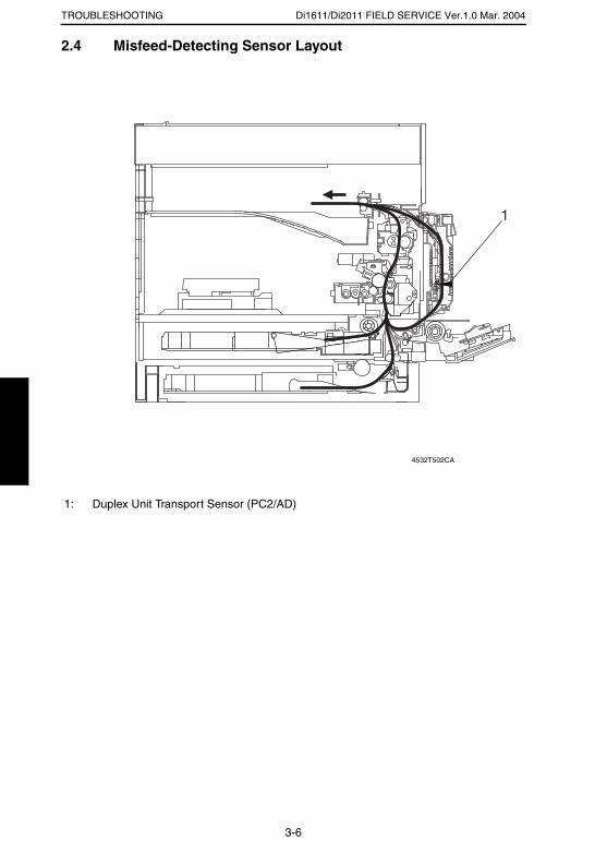
Di1611/Di2011 FIELD SERVICE Ver.1.0 Mar. 2004TROUBLESHOOTING
2.4 Misfeed-Detecting Sensor Layout
1: Duplex Unit Transport Sensor (PC2/AD)
4532T502CA
3-6
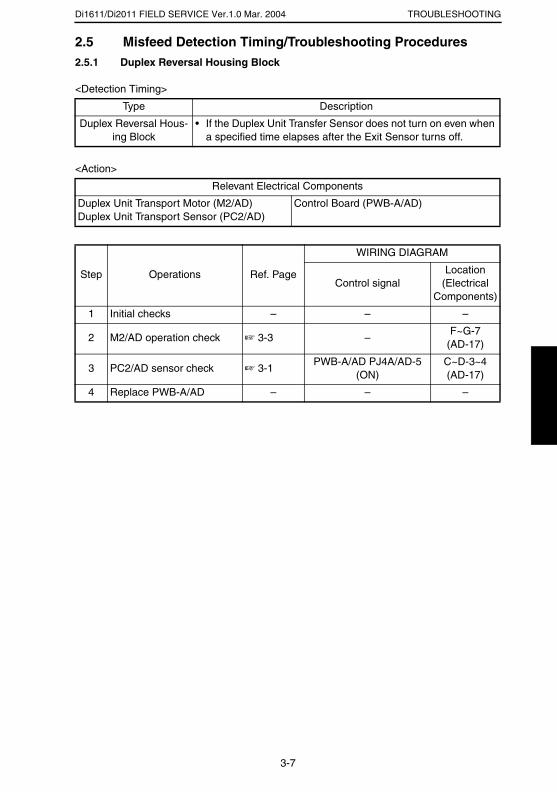
Di1611/Di2011 FIELD SERVICE Ver.1.0 Mar. 2004 TROUBLESHOOTING
2.5 Misfeed Detection Timing/Troubleshooting Procedures2.5.1 Duplex Reversal Housing Block
<Detection Timing>
<Action>
Type Description
Duplex Reversal Hous-ing Block
• If the Duplex Unit Transfer Sensor does not turn on even when a specified time elapses after the Exit Sensor turns off.
Relevant Electrical Components
Duplex Unit Transport Motor (M2/AD)Duplex Unit Transport Sensor (PC2/AD)
Control Board (PWB-A/AD)
Step Operations Ref. Page
WIRING DIAGRAM
Control signalLocation
(Electrical Components)
1 Initial checks – – –
2 M2/AD operation check ☞ 3-3 –F~G-7
(AD-17)
3 PC2/AD sensor check ☞ 3-1PWB-A/AD PJ4A/AD-5
(ON)C~D-3~4 (AD-17)
4 Replace PWB-A/AD – – –
3-7
SERVICE MANUAL
2004.3Ver. 1.0
FIELD SERVICE
PF-126

INDEX
ADJUSTMENT/SETTING
MAINTENANCE
TROUBLESHOOTING
i
CONTENTS
MAINTENANCE1. MAINTENANCE SCHEDULE .......................................................................... 1-1
1.1 PM Parts List ............................................................................................ 1-11.2 Replacement and Cleaning of Parts ........................................................ 1-1
(1) Removal of the Paper Take-Up Rollers ................................. 1-1(2) Cleaning of the Paper Take-up Rollers .................................. 1-2(3) Cleaning of the Vertical Transport Roller/Rolls ...................... 1-2
2. MISCELLANEOUS PARTS .............................................................................. 1-32.1 Disassembly and Reassembly ................................................................. 1-3
(1) Identification and Removal Procedures of Doors, Covers, and Exterior ............................................................................ 1-3
2.1.1 Removal of Circuit Boards and Other Electric Components .......... 1-4(1) Removal of the Control Board (PWB-A/PF) ........................... 1-4(2) Removal of the Paper Size (FD)
Detection Board (PWB-I/PF) .................................................. 1-5
ADJUSTING/SETTING1. SERVICE MODE .............................................................................................. 2-1
1.1 Service Mode Function Setting Procedure ............................................... 2-11.2 Setting in the Service Mode ..................................................................... 2-2
1.2.1 SERVICE’S CHOICE ..................................................................... 2-2(1) LOOP ADJUST (TRAY2 TO TRAY5) .................................... 2-2
1.2.2 FUNCTION .................................................................................... 2-2(1) PAPER FEED TEST .............................................................. 2-2
2. MECHANICAL ADJUSTMENTS ...................................................................... 2-32.1 Paper Feed Unit CD Registration Adjustment .......................................... 2-3
TROUBLESHOOTING1. INTRODUCTION .............................................................................................. 3-1
1.1 Electrical Components Check Procedure ................................................ 3-11.1.1 Sensor ........................................................................................... 3-11.1.2 Switch ............................................................................................ 3-21.1.3 Solenoid ......................................................................................... 3-21.1.4 Clutch ............................................................................................ 3-21.1.5 Motor ............................................................................................. 3-3
2. MISFEEDS ....................................................................................................... 3-42.1 Initial Checks ............................................................................................ 3-42.2 Paper Misfeed Detection .......................................................................... 3-4
2.2.1 Outline ........................................................................................... 3-42.3 Misfeed Display ........................................................................................ 3-52.4 Misfeed-Detecting Sensor Layout ............................................................ 3-62.5 Misfeed Detection Timing/Troubleshooting Procedures .......................... 3-7
2.5.1 Misfeed at the Paper Feed Unit Paper Take-up/ Vertical Transport Section ............................................................. 3-7

MAINTENANCE
19971
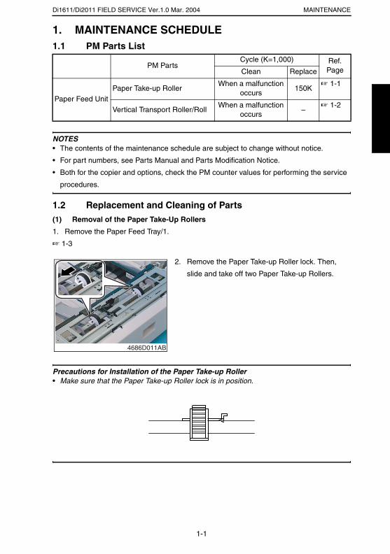
Di1611/Di2011 FIELD SERVICE Ver.1.0 Mar. 2004 MAINTENANCE
1. MAINTENANCE SCHEDULE1.1 PM Parts List
NOTES• The contents of the maintenance schedule are subject to change without notice.
• For part numbers, see Parts Manual and Parts Modification Notice.
• Both for the copier and options, check the PM counter values for performing the service
procedures.
1.2 Replacement and Cleaning of Parts(1) Removal of the Paper Take-Up Rollers
1. Remove the Paper Feed Tray/1.
☞ 1-3
Precautions for Installation of the Paper Take-up Roller• Make sure that the Paper Take-up Roller lock is in position.
PM PartsCycle (K=1,000) Ref.
PageClean Replace
Paper Feed UnitPaper Take-up Roller
When a malfunction occurs
150K☞ 1-1
Vertical Transport Roller/RollWhen a malfunction
occurs–
☞ 1-2
2. Remove the Paper Take-up Roller lock. Then,
slide and take off two Paper Take-up Rollers.
4686D011AB
1-1
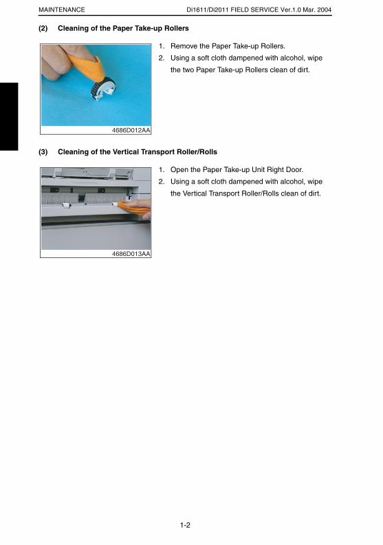
Di1611/Di2011 FIELD SERVICE Ver.1.0 Mar. 2004MAINTENANCE
(2) Cleaning of the Paper Take-up Rollers
(3) Cleaning of the Vertical Transport Roller/Rolls
1. Remove the Paper Take-up Rollers.
2. Using a soft cloth dampened with alcohol, wipe
the two Paper Take-up Rollers clean of dirt.
4686D012AA
1. Open the Paper Take-up Unit Right Door.
2. Using a soft cloth dampened with alcohol, wipe
the Vertical Transport Roller/Rolls clean of dirt.
4686D013AA
1-2
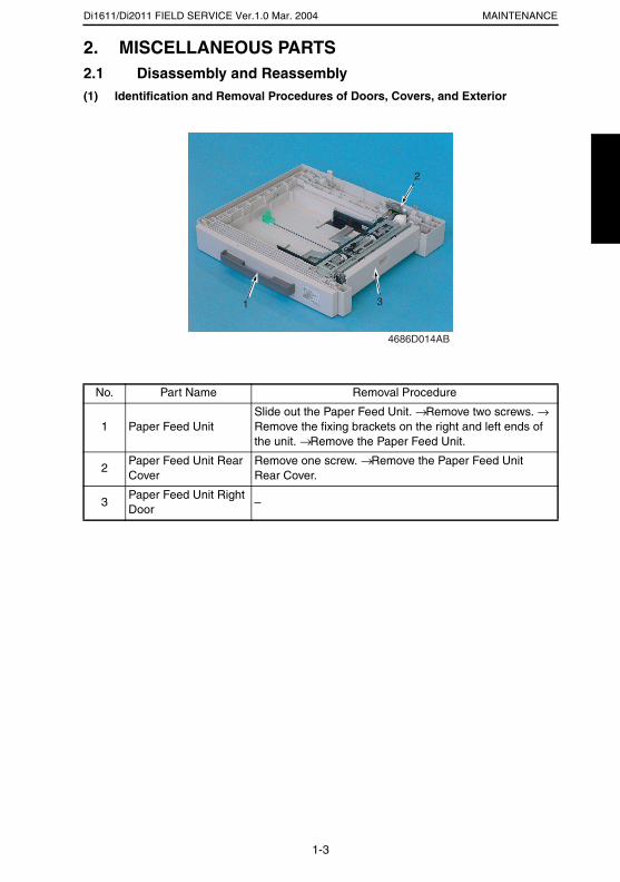
Di1611/Di2011 FIELD SERVICE Ver.1.0 Mar. 2004 MAINTENANCE
2. MISCELLANEOUS PARTS2.1 Disassembly and Reassembly(1) Identification and Removal Procedures of Doors, Covers, and Exterior
No. Part Name Removal Procedure
1 Paper Feed UnitSlide out the Paper Feed Unit. → Remove two screws. → Remove the fixing brackets on the right and left ends of the unit. → Remove the Paper Feed Unit.
2Paper Feed Unit Rear Cover
Remove one screw. → Remove the Paper Feed Unit Rear Cover.
3Paper Feed Unit Right Door
–
4686D014AB
1 3
2
1-3
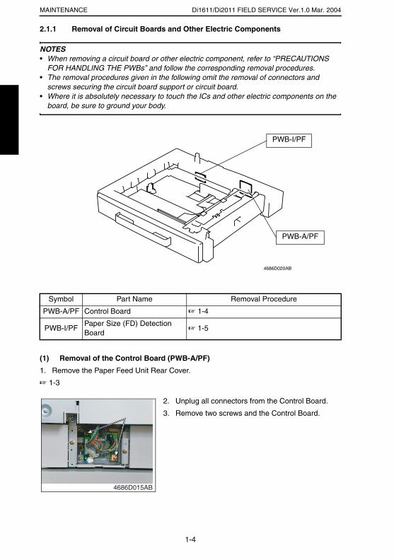
Di1611/Di2011 FIELD SERVICE Ver.1.0 Mar. 2004MAINTENANCE
2.1.1 Removal of Circuit Boards and Other Electric Components
NOTES• When removing a circuit board or other electric component, refer to “PRECAUTIONS
FOR HANDLING THE PWBs” and follow the corresponding removal procedures.• The removal procedures given in the following omit the removal of connectors and
screws securing the circuit board support or circuit board.• Where it is absolutely necessary to touch the ICs and other electric components on the
board, be sure to ground your body.
(1) Removal of the Control Board (PWB-A/PF)
1. Remove the Paper Feed Unit Rear Cover.
☞ 1-3
Symbol Part Name Removal Procedure
PWB-A/PF Control Board ☞ 1-4
PWB-I/PFPaper Size (FD) Detection Board
☞ 1-5
PWB-A/PF
4686D020AB
PWB-I/PF
2. Unplug all connectors from the Control Board.
3. Remove two screws and the Control Board.
4686D015AB
1-4
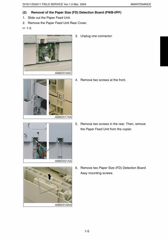
Di1611/Di2011 FIELD SERVICE Ver.1.0 Mar. 2004 MAINTENANCE
(2) Removal of the Paper Size (FD) Detection Board (PWB-I/PF)
1. Slide out the Paper Feed Unit.
2. Remove the Paper Feed Unit Rear Cover.
☞ 1-3
3. Unplug one connector.
4686D016AC
4. Remove two screws at the front.
4686D017AA
5. Remove two screws in the rear. Then, remove
the Paper Feed Unit from the copier.
4686D021AA
6. Remove two Paper Size (FD) Detection Board
Assy mounting screws.
4686D018AA
1-5
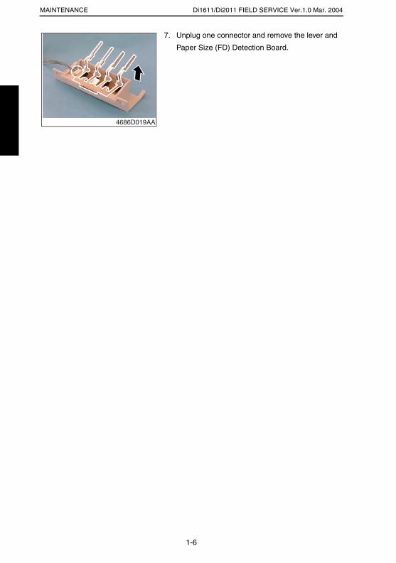
Di1611/Di2011 FIELD SERVICE Ver.1.0 Mar. 2004MAINTENANCE
7. Unplug one connector and remove the lever and
Paper Size (FD) Detection Board.
4686D019AA
1-6

ADJUSTING/SETTING
19971

Di1611/Di2011 FIELD SERVICE Ver.1.0 Mar. 2004ADJUSTING/SETTING
1. SERVICE MODE1.1 Service Mode Function Setting Procedure
NOTE• Care must be used to ensure that only the personnel who are involved in service jobs
know the procedure to enter the Service mode.
<Procedure>
1. Press the Utility key.
2. Press the following keys in this order.
3. Stop → 0 → 0 → Stop → 0 → 1
4. The Service mode menu screen will appear.
<Exiting the Mode>
• Press the Panel Reset key as many times as it is required to display the initial screen.
<Service Mode Function Setting Value Changing Procedure>
1. Select the desired item using [ ▲ / ▼ ] key.
2. Select the setting value using [ ▲ / ▼ ] key, [ < / > ] key, or the 10-Key Pad.
3. Validate the selection by pressing the [Yes] key.
4. To go back to previous screen, press the [No] key.
2-1
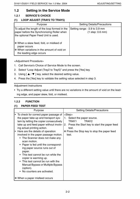
Di1611/Di2011 FIELD SERVICE Ver.1.0 Mar. 2004 ADJUSTING/SETTING
1.2 Setting in the Service Mode1.2.1 SERVICE’S CHOICE
(1) LOOP ADJUST (TRAY2 TO TRAY5)
<Adjustment Procedure>
1. Call Service’s Choice of Service Mode to the screen.
2. Select “Loop Adjust (Tray2 to Tray5)” and press the [Yes] key.
3. Using [ ▲ / ▼ ] key, select the desired setting value.
4. Press the [Yes] key to validate the setting value selected in step 3.
Adjustment Instructions
• Try a different setting value until there are no variations in the amount of void on the lead-
ing edge, and paper skew, fold, or misfeed.
1.2.2 FUNCTION
(1) PAPER FEED TEST
Purpose Setting Details/Precautions
To adjust the length of the loop formed in the paper before the Synchronizing Roller when the optional Paper Feed Unit is used.
✽ When a skew feed, fold, or misfeed of paper occurs
✽ When variations in the amount of void on the leading edge occurs
Setting range: -3.9 to 3.9 mm (1 step: 0.6 mm)
Purpose Setting Details/Precautions
• To check for correct paper passage of the paper take-up and transport sys-tem by letting the copier consecutively take up and feed paper without involv-ing actual printing action.
• Here are the details of operation involved in the paper passage motion.
• The Scanner does not make any scan motion.
• Paper is fed until the correspond-ing paper source runs out of paper.
• This test cannot be run while the copier is warming up.
• This test cannot be run with the Manual Bypass or Multiple Bypass (option).
• No counters are activated.
✽ When a paper misfeed occurs
<Step>1. Select the paper source.
TRAY1 TRAY22. Press the Start key to start the paper feed
test.✽ Press the Stop key to stop the paper feed
test.
2-2
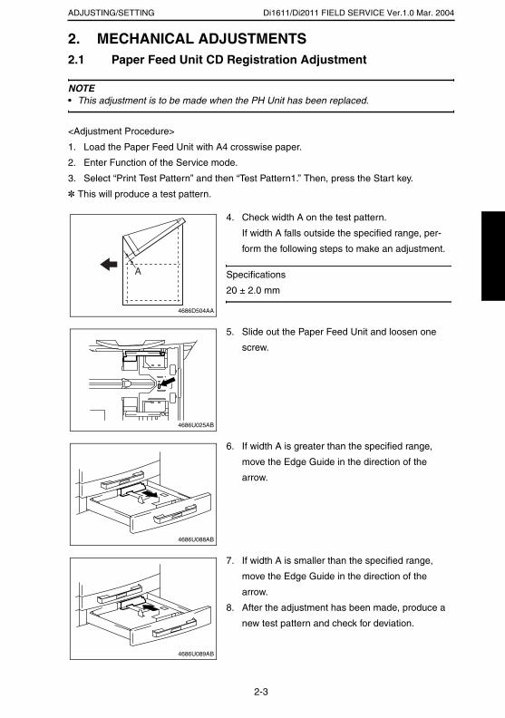
Di1611/Di2011 FIELD SERVICE Ver.1.0 Mar. 2004ADJUSTING/SETTING
2. MECHANICAL ADJUSTMENTS2.1 Paper Feed Unit CD Registration Adjustment
NOTE• This adjustment is to be made when the PH Unit has been replaced.
<Adjustment Procedure>
1. Load the Paper Feed Unit with A4 crosswise paper.
2. Enter Function of the Service mode.
3. Select “Print Test Pattern” and then “Test Pattern1.” Then, press the Start key.
✽ This will produce a test pattern.
4. Check width A on the test pattern.
If width A falls outside the specified range, per-
form the following steps to make an adjustment.
Specifications
20 ± 2.0 mm
A
4686D504AA
5. Slide out the Paper Feed Unit and loosen one
screw.
4686U025AB
6. If width A is greater than the specified range,
move the Edge Guide in the direction of the
arrow.
4686U088AB
7. If width A is smaller than the specified range,
move the Edge Guide in the direction of the
arrow.
8. After the adjustment has been made, produce a
new test pattern and check for deviation.
4686U089AB
2-3
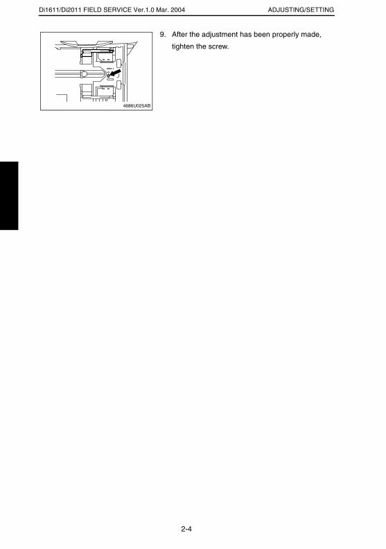
Di1611/Di2011 FIELD SERVICE Ver.1.0 Mar. 2004 ADJUSTING/SETTING
9. After the adjustment has been properly made,
tighten the screw.
4686U025AB
2-4

TROUBLESHOOTING
19971

Di1611/Di2011 FIELD SERVICE Ver.1.0 Mar. 2004 TROUBLESHOOTING
1. INTRODUCTION
• Information required for troubleshooting and steps that must be performed are described
in this chapter.
1.1 Electrical Components Check Procedure• If a paper misfeed or malfunction occurs, perform the following operations to check the
condition of the electrical components.
1.1.1 Sensor
Step Check Result Action
1 Does the input signal of the control board change when the sensor light is interrupted? (H → L, L → H)
NO Replace the sensor.
YES Replace the control board.
4025T520AA
4025T521AA
3-1

Di1611/Di2011 FIELD SERVICE Ver.1.0 Mar. 2004TROUBLESHOOTING
1.1.2 Switch
1.1.3 Solenoid
1.1.4 Clutch
Step Check Result Action
1 Does the input signal (NO) of the control board change from L to H when the switch is activated?
NO Replace the switch.
YES Replace the control board.
Step Check Result Action
1 Does the output signal of the control board change from H to L when the solenoid is activated?
NO Replace the control board.
YES Replace the solenoid.
Step Check Result Action
1 Does the output signal of the control board change from H to L when the clutch is activated?
NO Replace the control board.
YES Replace the clutch.
Not UseCOM
NO
4025T523AB
12
212
1
4025T522AA
4025T528AA
3-2

Di1611/Di2011 FIELD SERVICE Ver.1.0 Mar. 2004 TROUBLESHOOTING
1.1.5 Motor
Step Check Result Action
1 Does the LOCK signal switch to H when the machine goes into standby?
NO Replace the con-trol board. Replace the motor.
2 Does the REM signal of the master board change from H to L when the motor is turned on?
YES Replace the motor.
NO Replace the con-trol board.
Step Check Result Action
1 Does the input signal of the master board change from H to L when the motor is turned on?(The input signal differs depending on the rotation direction.)
YES Replace the motor.
NO Replace the con-trol board.
Step Check Result Action
1 Are the relay connector of the motor and the print jack of the control board correctly connected?
YES Replace the motor or the control board.
NO Connect the con-nector or the print jack.
GND
REM
LOCK
2
1
3
4025T526AA
4025T525AA
4025T527AA
3-3

Di1611/Di2011 FIELD SERVICE Ver.1.0 Mar. 2004TROUBLESHOOTING
2. MISFEEDS2.1 Initial Checks• When a paper misfeed occurs, first perform the following initial checks.
2.2 Paper Misfeed Detection2.2.1 Outline
• A paper misfeed is detected by detecting different states of signals (H, L) of several sen-
sors located near the paper take-up section and the Exit Paper Sensor. The copier
thereby determines whether there is paper left inside it.
• The timings of the rising and falling edges of the paper take-up-related sensors and the
Exit Paper Sensor are monitored to detect a misfeed of paper being fed through the
copier.
• The states (H, L) of the paper take-up-related sensors and the Exit Paper Sensor are
monitored to detect a sheet of paper left in the copier.
• All drives are brought to a stop when a sheet of paper misfed or left in the copier is
detected.
Check Item Action
Does paper meet product specifications? Replace paper.
Is the paper curled, wavy, or damp? Replace paper.Instruct the user on the correct paper storage procedures.
Is a foreign object present along the paper path, or is the paper path deformed or worn?
Clean or change the paper path.
Are the Paper Separator Fingers dirty, deformed, or worn?
Clean or replace the defective Paper Separator Finger.
Are rolls/rollers dirty, deformed, or worn? Clean or replace the defective roll/roller.
Are the Edge Guide and Trailing Edge Stop at the correct position to accommodate the paper?
Set as necessary.
Are the actuators operational and checked for correct operation?
Correct or replace the defective actua-tor.
3-4
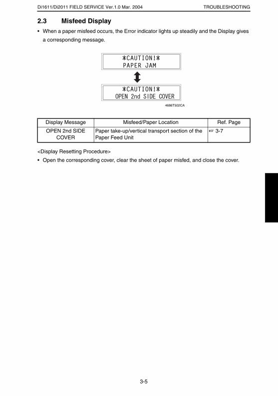
Di1611/Di2011 FIELD SERVICE Ver.1.0 Mar. 2004 TROUBLESHOOTING
2.3 Misfeed Display• When a paper misfeed occurs, the Error indicator lights up steadily and the Display gives
a corresponding message.
<Display Resetting Procedure>
• Open the corresponding cover, clear the sheet of paper misfed, and close the cover.
Display Message Misfeed/Paper Location Ref. Page
OPEN 2nd SIDE COVER
Paper take-up/vertical transport section of the Paper Feed Unit
☞ 3-7
4686T502CA
3-5
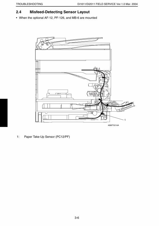
Di1611/Di2011 FIELD SERVICE Ver.1.0 Mar. 2004TROUBLESHOOTING
2.4 Misfeed-Detecting Sensor Layout• When the optional AF-12, PF-126, and MB-6 are mounted
1: Paper Take-Up Sensor (PC12/PF)
1
4686T501AA
3-6
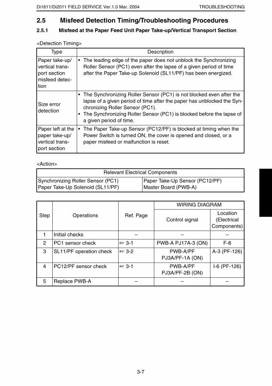
Di1611/Di2011 FIELD SERVICE Ver.1.0 Mar. 2004 TROUBLESHOOTING
2.5 Misfeed Detection Timing/Troubleshooting Procedures2.5.1 Misfeed at the Paper Feed Unit Paper Take-up/Vertical Transport Section
<Detection Timing>
<Action>
Type Description
Paper take-up/vertical trans-port section misfeed detec-tion
• The leading edge of the paper does not unblock the Synchronizing Roller Sensor (PC1) even after the lapse of a given period of time after the Paper Take-up Solenoid (SL11/PF) has been energized.
Size error detection
• The Synchronizing Roller Sensor (PC1) is not blocked even after the lapse of a given period of time after the paper has unblocked the Syn-chronizing Roller Sensor (PC1).
• The Synchronizing Roller Sensor (PC1) is blocked before the lapse of a given period of time.
Paper left at the paper take-up/vertical trans-port section
• The Paper Take-up Sensor (PC12/PF) is blocked at timing when the Power Switch is turned ON, the cover is opened and closed, or a paper misfeed or malfunction is reset.
Relevant Electrical Components
Synchronizing Roller Sensor (PC1)Paper Take-Up Solenoid (SL11/PF)
Paper Take-Up Sensor (PC12/PF)Master Board (PWB-A)
Step Operations Ref. Page
WIRING DIAGRAM
Control signalLocation
(Electrical Components)
1 Initial checks – – –
2 PC1 sensor check ☞ 3-1 PWB-A PJ17A-3 (ON) F-8
3 SL11/PF operation check ☞ 3-2 PWB-A/PF PJ3A/PF-1A (ON)
A-3 (PF-126)
4 PC12/PF sensor check ☞ 3-1 PWB-A/PF PJ3A/PF-2B (ON)
I-6 (PF-126)
5 Replace PWB-A – – –
3-7

SERVICE MANUAL
2004.3Ver. 1.0
FIELD SERVICE
MB-6

INDEX
ADJUSTMENT/SETTING
MAINTENANCE
TROUBLESHOOTING

i
CONTENTS
MAINTENANCE1. MAINTENANCE SCHEDULE .......................................................................... 1-1
1.1 PM Parts List ............................................................................................ 1-11.2 Replacement and Cleaning Parts ............................................................ 1-2
(1) Removal of the Separator Roller Assy ................................... 1-2(2) Cleaning of the Separator Roller ............................................ 1-2(3) Removal of the Paper Take-up Roller .................................... 1-2(4) Cleaning of the Paper Take-up Roller .................................... 1-4(5) Cleaning of the Bypass Transport Roller/Rolls ...................... 1-5
2. MISCELLANEOUS PARTS .............................................................................. 1-62.1 Disassembly and Reassembly ................................................................. 1-6
(1) Indentification and Removal Procedures of Doors, and Exterior Parts .................................................................. 1-6
2.1.1 Removal of Units ........................................................................... 1-7(1) Removal of the Multiple Bypass ............................................. 1-7
2.1.2 Disassembly of the Optional Multiple Bypass (MB-6) .................... 1-9(1) Removal and Disassembly of the Paper Take-up
Mechanical Clutch .................................................................. 1-9
ADJUSTING/SETTING1. SERVICE MODE .............................................................................................. 2-1
1.1 Service Mode Function Setting Procedure ............................................... 2-11.2 Setting in the Service Mode ..................................................................... 2-2
1.2.1 SERVICE’S CHOICE ..................................................................... 2-2(1) LOOP ADJUST (BYPASS) .................................................... 2-2
2. MECHANICAL ADJUSTMENTS ...................................................................... 2-32.1 Multiple Bypass CD Registration Adjustment ........................................... 2-32.2 Multiple Bypass Mechanical Clutch Adjustment ....................................... 2-4
TROUBLESHOOTING1. INTRODUCTION .............................................................................................. 3-1
1.1 Electrical Components Check Procedure ................................................ 3-11.1.1 Sensor ........................................................................................... 3-11.1.2 Switch ............................................................................................ 3-21.1.3 Solenoid ......................................................................................... 3-21.1.4 Clutch ............................................................................................ 3-21.1.5 Motor ............................................................................................. 3-3
2. MISFEEDS ....................................................................................................... 3-42.1 Initial Checks ............................................................................................ 3-42.2 Paper Misfeed Detection .......................................................................... 3-4
2.2.1 Outline ........................................................................................... 3-42.3 Misfeed Display ........................................................................................ 3-52.4 Misfeed-Detecting Sensor Layout ............................................................ 3-62.5 Misfeed Detection Timing/Troubleshooting Procedures .......................... 3-7
2.5.1 Misfeed at the Multiple Bypass Paper Take-up Section ................ 3-7

MAINTENANCE
19971
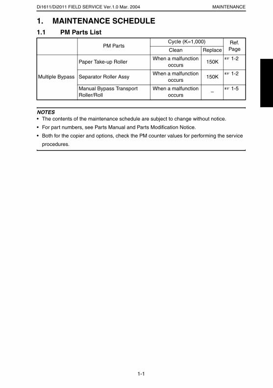
Di1611/Di2011 FIELD SERVICE Ver.1.0 Mar. 2004 MAINTENANCE
1. MAINTENANCE SCHEDULE1.1 PM Parts List
NOTES• The contents of the maintenance schedule are subject to change without notice.
• For part numbers, see Parts Manual and Parts Modification Notice.
• Both for the copier and options, check the PM counter values for performing the service
procedures.
PM PartsCycle (K=1,000) Ref.
PageClean Replace
Multiple Bypass
Paper Take-up RollerWhen a malfunction
occurs150K
☞ 1-2
Separator Roller AssyWhen a malfunction
occurs150K
☞ 1-2
Manual Bypass Transport Roller/Roll
When a malfunction occurs
–☞ 1-5
1-1

Di1611/Di2011 FIELD SERVICE Ver.1.0 Mar. 2004MAINTENANCE
1.2 Replacement and Cleaning Parts(1) Removal of the Separator Roller Assy
(2) Cleaning of the Separator Roller
(3) Removal of the Paper Take-up Roller
1. Remove the Rear Right Cover.
1. Open the Right Door.
2. Remove the two screws and the Separator Roller
Assy.
4687D001AA
1. Remove the Separator Roller Assy.
2. Using a soft cloth dampened with alcohol, wipe
the Separator Roller clean of dirt.
4687D002AA
2. Open the Right Door.
3. Unplug two connectors.
4687D010AA
1-2
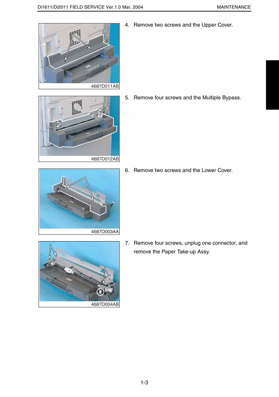
Di1611/Di2011 FIELD SERVICE Ver.1.0 Mar. 2004 MAINTENANCE
4. Remove two screws and the Upper Cover.
4687D011AB
5. Remove four screws and the Multiple Bypass.
4687D012AB
6. Remove two screws and the Lower Cover.
4687D003AA
7. Remove four screws, unplug one connector, and
remove the Paper Take-up Assy.
4687D004AB
1-3
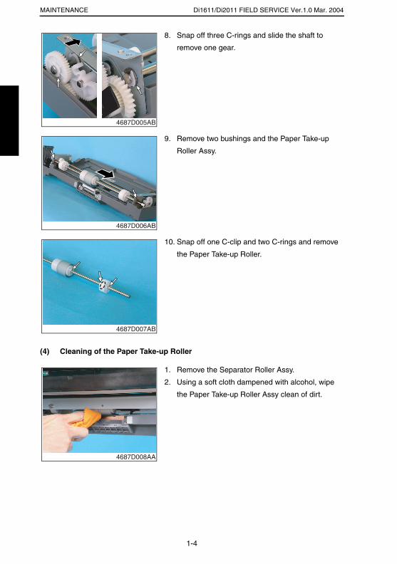
Di1611/Di2011 FIELD SERVICE Ver.1.0 Mar. 2004MAINTENANCE
(4) Cleaning of the Paper Take-up Roller
8. Snap off three C-rings and slide the shaft to
remove one gear.
4687D005AB
9. Remove two bushings and the Paper Take-up
Roller Assy.
4687D006AB
10. Snap off one C-clip and two C-rings and remove
the Paper Take-up Roller.
4687D007AB
1. Remove the Separator Roller Assy.
2. Using a soft cloth dampened with alcohol, wipe
the Paper Take-up Roller Assy clean of dirt.
4687D008AA
1-4
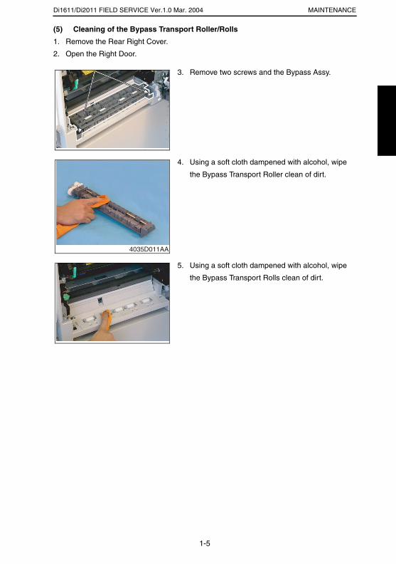
Di1611/Di2011 FIELD SERVICE Ver.1.0 Mar. 2004 MAINTENANCE
(5) Cleaning of the Bypass Transport Roller/Rolls
1. Remove the Rear Right Cover.
2. Open the Right Door.
3. Remove two screws and the Bypass Assy.
4035D010AA
4. Using a soft cloth dampened with alcohol, wipe
the Bypass Transport Roller clean of dirt.
4035D011AA
5. Using a soft cloth dampened with alcohol, wipe
the Bypass Transport Rolls clean of dirt.
4035D012AA
1-5
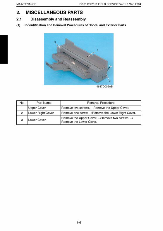
Di1611/Di2011 FIELD SERVICE Ver.1.0 Mar. 2004MAINTENANCE
2. MISCELLANEOUS PARTS2.1 Disassembly and Reassembly(1) Indentification and Removal Procedures of Doors, and Exterior Parts
No. Part Name Removal Procedure
1 Upper Cover Remove two screws. → Remove the Upper Cover.
2 Lower Right Cover Remove one screw. → Remove the Lower Right Cover.
3 Lower CoverRemove the Upper Cover. → Remove two screws. → Remove the Lower Cover.
4687D009AB
1
3
2
1-6
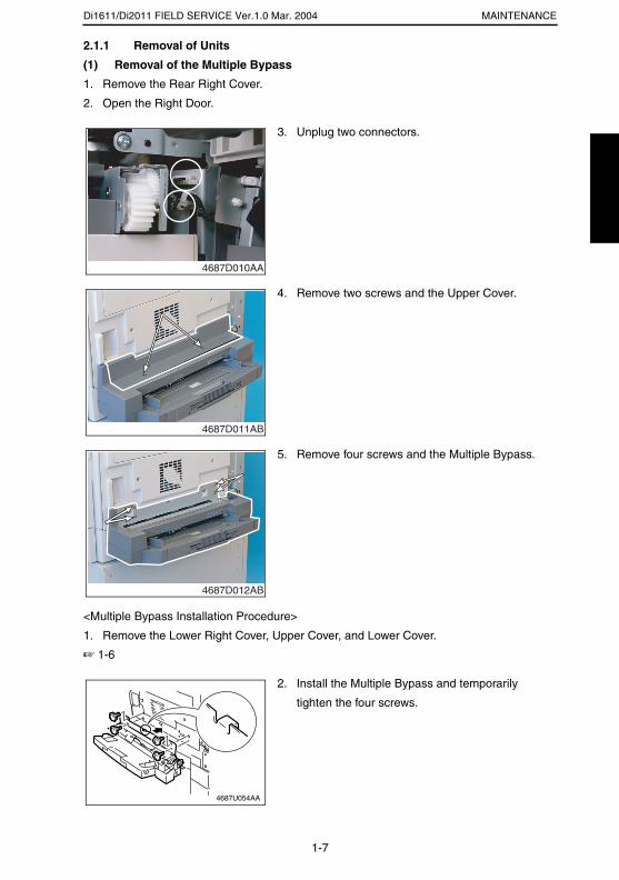
Di1611/Di2011 FIELD SERVICE Ver.1.0 Mar. 2004 MAINTENANCE
2.1.1 Removal of Units
(1) Removal of the Multiple Bypass
1. Remove the Rear Right Cover.
2. Open the Right Door.
<Multiple Bypass Installation Procedure>
1. Remove the Lower Right Cover, Upper Cover, and Lower Cover.
☞ 1-6
3. Unplug two connectors.
4687D010AA
4. Remove two screws and the Upper Cover.
4687D011AB
5. Remove four screws and the Multiple Bypass.
4687D012AB
2. Install the Multiple Bypass and temporarily
tighten the four screws.
4687U054AA
1-7
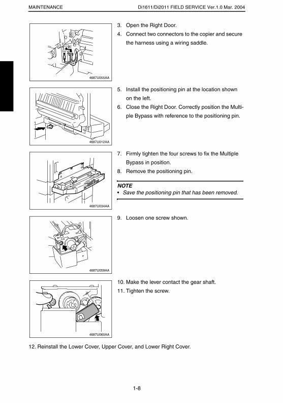
Di1611/Di2011 FIELD SERVICE Ver.1.0 Mar. 2004MAINTENANCE
12. Reinstall the Lower Cover, Upper Cover, and Lower Right Cover.
3. Open the Right Door.
4. Connect two connectors to the copier and secure
the harness using a wiring saddle.
4687U055AA
5. Install the positioning pin at the location shown
on the left.
6. Close the Right Door. Correctly position the Multi-
ple Bypass with reference to the positioning pin.
4687U012AA
7. Firmly tighten the four screws to fix the Multiple
Bypass in position.
8. Remove the positioning pin.
NOTE• Save the positioning pin that has been removed.
4687U034AA
9. Loosen one screw shown.
4687U059AA
10. Make the lever contact the gear shaft.
11. Tighten the screw.
4687U060AA
1-8
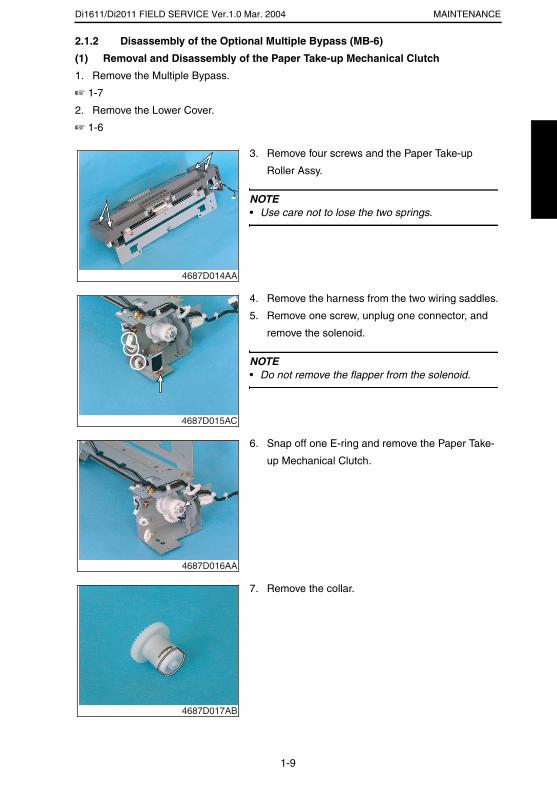
Di1611/Di2011 FIELD SERVICE Ver.1.0 Mar. 2004 MAINTENANCE
2.1.2 Disassembly of the Optional Multiple Bypass (MB-6)
(1) Removal and Disassembly of the Paper Take-up Mechanical Clutch
1. Remove the Multiple Bypass.
☞ 1-7
2. Remove the Lower Cover.
☞ 1-6
3. Remove four screws and the Paper Take-up
Roller Assy.
NOTE• Use care not to lose the two springs.
4687D014AA
4. Remove the harness from the two wiring saddles.
5. Remove one screw, unplug one connector, and
remove the solenoid.
NOTE• Do not remove the flapper from the solenoid.
4687D015AC
6. Snap off one E-ring and remove the Paper Take-
up Mechanical Clutch.
4687D016AA
7. Remove the collar.
4687D017AB
1-9
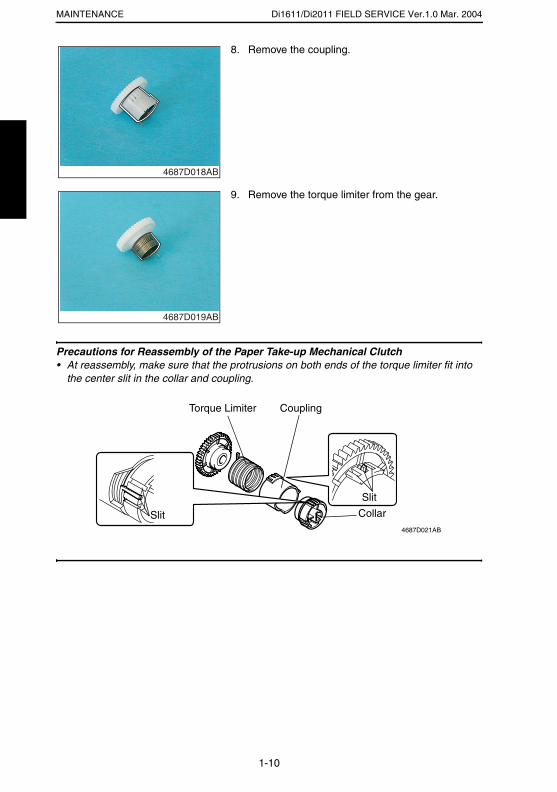
Di1611/Di2011 FIELD SERVICE Ver.1.0 Mar. 2004MAINTENANCE
Precautions for Reassembly of the Paper Take-up Mechanical Clutch• At reassembly, make sure that the protrusions on both ends of the torque limiter fit into
the center slit in the collar and coupling.
8. Remove the coupling.
4687D018AB
9. Remove the torque limiter from the gear.
4687D019AB
4687D021AB
Torque Limiter Coupling
Collar
Slit
Slit
1-10

ADJUSTING/SETTING
19971
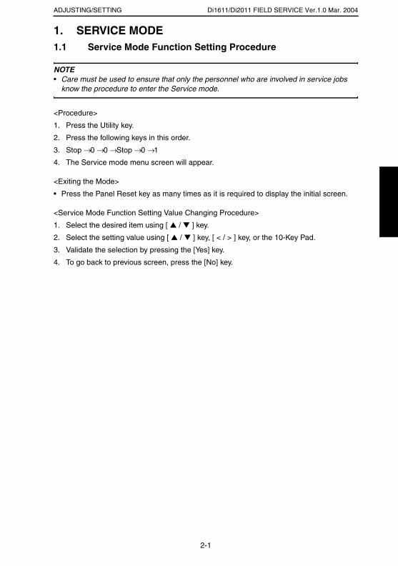
Di1611/Di2011 FIELD SERVICE Ver.1.0 Mar. 2004ADJUSTING/SETTING
1. SERVICE MODE1.1 Service Mode Function Setting Procedure
NOTE• Care must be used to ensure that only the personnel who are involved in service jobs
know the procedure to enter the Service mode.
<Procedure>
1. Press the Utility key.
2. Press the following keys in this order.
3. Stop → 0 → 0 → Stop → 0 → 1
4. The Service mode menu screen will appear.
<Exiting the Mode>
• Press the Panel Reset key as many times as it is required to display the initial screen.
<Service Mode Function Setting Value Changing Procedure>
1. Select the desired item using [ ▲ / ▼ ] key.
2. Select the setting value using [ ▲ / ▼ ] key, [ < / > ] key, or the 10-Key Pad.
3. Validate the selection by pressing the [Yes] key.
4. To go back to previous screen, press the [No] key.
2-1
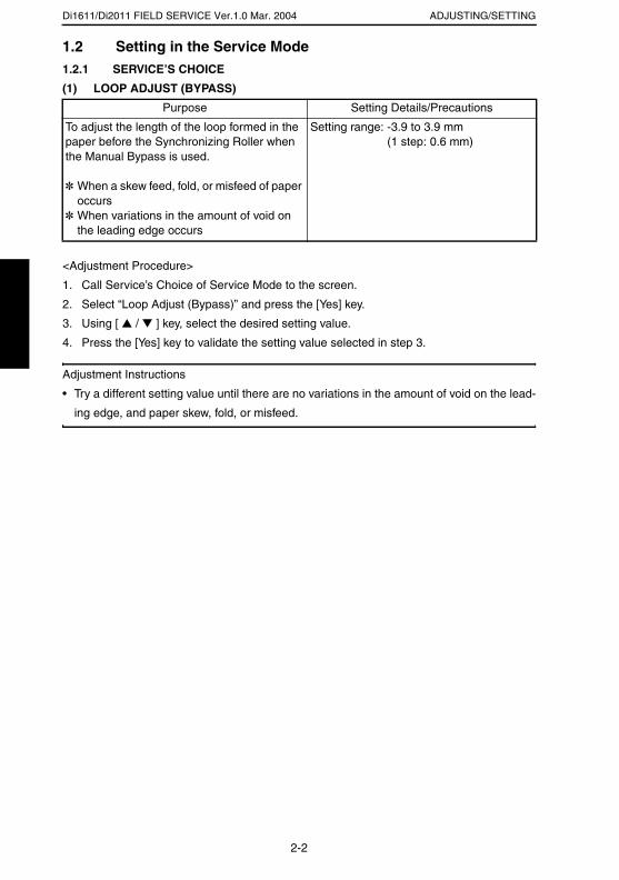
Di1611/Di2011 FIELD SERVICE Ver.1.0 Mar. 2004 ADJUSTING/SETTING
1.2 Setting in the Service Mode1.2.1 SERVICE’S CHOICE
(1) LOOP ADJUST (BYPASS)
<Adjustment Procedure>
1. Call Service’s Choice of Service Mode to the screen.
2. Select “Loop Adjust (Bypass)” and press the [Yes] key.
3. Using [ ▲ / ▼ ] key, select the desired setting value.
4. Press the [Yes] key to validate the setting value selected in step 3.
Adjustment Instructions
• Try a different setting value until there are no variations in the amount of void on the lead-
ing edge, and paper skew, fold, or misfeed.
Purpose Setting Details/Precautions
To adjust the length of the loop formed in the paper before the Synchronizing Roller when the Manual Bypass is used.
✽ When a skew feed, fold, or misfeed of paper occurs
✽ When variations in the amount of void on the leading edge occurs
Setting range: -3.9 to 3.9 mm (1 step: 0.6 mm)
2-2

Di1611/Di2011 FIELD SERVICE Ver.1.0 Mar. 2004ADJUSTING/SETTING
2. MECHANICAL ADJUSTMENTS2.1 Multiple Bypass CD Registration Adjustment
NOTE• This adjustment is to be made when the PH Unit has been replaced.
<Adjustment Procedure>
1. Load the Paper Feed Tray/1 with A4 crosswise paper.
2. Enter Function of the Service mode.
3. Select “Print Test Pattern” and then “Test Pattern1.” Then, press the Start key.
✽ This will produce a test pattern.
4. Place the test pattern produced on the Original Glass.
5. Load A4 crosswise paper in the Multiple Bypass and make a test copy.
6. Check width A on the copy of the test pattern. If width A falls outside the specified range, per-
form the following steps to make an adjustment.
Specifications
20 ± 2.0 mm
A
4686D504AA
7. Turn the screw of the Multiple Bypass as neces-
sary to adjust the position of the Multiple Bypass
table.
Adjustment Instructions
If width A on the copy is smaller than width A on the
test pattern, turn the screw clockwise.
If width A on the copy is greater than width A on the
test pattern, turn the screw counterclockwise.
8. Make another copy of the test pattern and check
for any error in width A.
4687U035AA
2-3
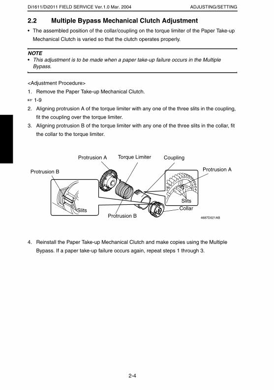
Di1611/Di2011 FIELD SERVICE Ver.1.0 Mar. 2004 ADJUSTING/SETTING
2.2 Multiple Bypass Mechanical Clutch Adjustment• The assembled position of the collar/coupling on the torque limiter of the Paper Take-up
Mechanical Clutch is varied so that the clutch operates properly.
NOTE• This adjustment is to be made when a paper take-up failure occurs in the Multiple
Bypass.
<Adjustment Procedure>
1. Remove the Paper Take-up Mechanical Clutch.
☞ 1-9
2. Aligning protrusion A of the torque limiter with any one of the three slits in the coupling,
fit the coupling over the torque limiter.
3. Aligning protrusion B of the torque limiter with any one of the three slits in the collar, fit
the collar to the torque limiter.
4. Reinstall the Paper Take-up Mechanical Clutch and make copies using the Multiple
Bypass. If a paper take-up failure occurs again, repeat steps 1 through 3.
4687D021AB
Torque Limiter Coupling
CollarSlits
Slits
Protrusion A
Protrusion B
Protrusion B Protrusion A
2-4

TROUBLESHOOTING
19971
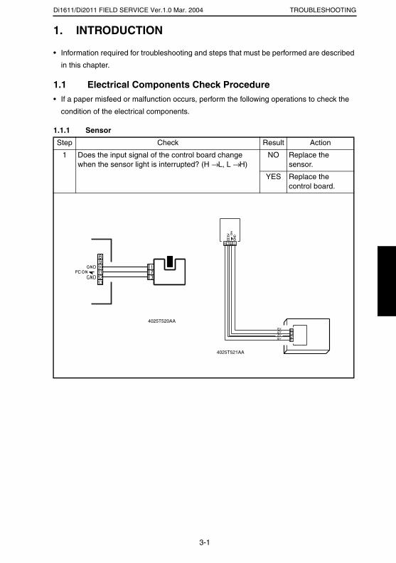
Di1611/Di2011 FIELD SERVICE Ver.1.0 Mar. 2004 TROUBLESHOOTING
1. INTRODUCTION
• Information required for troubleshooting and steps that must be performed are described
in this chapter.
1.1 Electrical Components Check Procedure• If a paper misfeed or malfunction occurs, perform the following operations to check the
condition of the electrical components.
1.1.1 Sensor
Step Check Result Action
1 Does the input signal of the control board change when the sensor light is interrupted? (H → L, L → H)
NO Replace the sensor.
YES Replace the control board.
4025T520AA
4025T521AA
3-1

Di1611/Di2011 FIELD SERVICE Ver.1.0 Mar. 2004TROUBLESHOOTING
1.1.2 Switch
1.1.3 Solenoid
1.1.4 Clutch
Step Check Result Action
1 Does the input signal (NO) of the control board change from L to H when the switch is activated?
NO Replace the switch.
YES Replace the control board.
Step Check Result Action
1 Does the output signal of the control board change from H to L when the solenoid is activated?
NO Replace the control board.
YES Replace the solenoid.
Step Check Result Action
1 Does the output signal of the control board change from H to L when the clutch is activated?
NO Replace the control board.
YES Replace the clutch.
Not UseCOM
NO
4025T523AB
12
212
1
4025T522AA
4025T528AA
3-2

Di1611/Di2011 FIELD SERVICE Ver.1.0 Mar. 2004 TROUBLESHOOTING
1.1.5 Motor
Step Check Result Action
1 Does the LOCK signal switch to H when the machine goes into standby?
NO Replace the con-trol board. Replace the motor.
2 Does the REM signal of the master board change from H to L when the motor is turned on?
YES Replace the motor.
NO Replace the con-trol board.
Step Check Result Action
1 Does the input signal of the master board change from H to L when the motor is turned on?(The input signal differs depending on the rotation direction.)
YES Replace the motor.
NO Replace the con-trol board.
Step Check Result Action
1 Are the relay connector of the motor and the print jack of the control board correctly connected?
YES Replace the motor or the control board.
NO Connect the con-nector or the print jack.
GND
REM
LOCK
2
1
3
4025T526AA
4025T525AA
4025T527AA
3-3

Di1611/Di2011 FIELD SERVICE Ver.1.0 Mar. 2004TROUBLESHOOTING
2. MISFEEDS2.1 Initial Checks• When a paper misfeed occurs, first perform the following initial checks.
2.2 Paper Misfeed Detection2.2.1 Outline
• A paper misfeed is detected by detecting different states of signals (H, L) of several sen-
sors located near the paper take-up section and the Exit Paper Sensor. The copier
thereby determines whether there is paper left inside it.
• The timings of the rising and falling edges of the paper take-up-related sensors and the
Exit Paper Sensor are monitored to detect a misfeed of paper being fed through the
copier.
• The states (H, L) of the paper take-up-related sensors and the Exit Paper Sensor are
monitored to detect a sheet of paper left in the copier.
• All drives are brought to a stop when a sheet of paper misfed or left in the copier is
detected.
Check Item Action
Does paper meet product specifications? Replace paper.
Is the paper curled, wavy, or damp? Replace paper.Instruct the user on the correct paper storage procedures.
Is a foreign object present along the paper path, or is the paper path deformed or worn?
Clean or change the paper path.
Are the Paper Separator Fingers dirty, deformed, or worn?
Clean or replace the defective Paper Separator Finger.
Are rolls/rollers dirty, deformed, or worn? Clean or replace the defective roll/roller.
Are the Edge Guide and Trailing Edge Stop at the correct position to accommodate the paper?
Set as necessary.
Are the actuators operational and checked for correct operation?
Correct or replace the defective actua-tor.
3-4

Di1611/Di2011 FIELD SERVICE Ver.1.0 Mar. 2004 TROUBLESHOOTING
2.3 Misfeed Display• When a paper misfeed occurs, the Error indicator lights up steadily and the Display gives
a corresponding message.
<Display Resetting Procedure>
• Open the corresponding cover, clear the sheet of paper misfed, and close the cover.
Display Message Misfeed/Paper Location Ref. Page
OPEN 1st SIDE COVER
Paper take-up section of the Multiple Bypass☞ 3-7
4980P502DA
3-5

Di1611/Di2011 FIELD SERVICE Ver.1.0 Mar. 2004TROUBLESHOOTING
2.4 Misfeed-Detecting Sensor Layout• When the optional AF-12, PF-126, and MB-6 are mounted
1: Synchronizing Roller Sensor (PC1)
1
4687T501AA
3-6
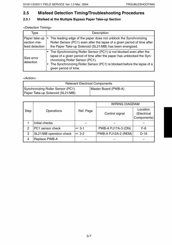
Di1611/Di2011 FIELD SERVICE Ver.1.0 Mar. 2004 TROUBLESHOOTING
2.5 Misfeed Detection Timing/Troubleshooting Procedures2.5.1 Misfeed at the Multiple Bypass Paper Take-up Section
<Detection Timing>
<Action>
Type Description
Paper take-up section mis-feed detection
• The leading edge of the paper does not unblock the Synchronizing Roller Sensor (PC1) even after the lapse of a given period of time after the Paper Take-up Solenoid (SL21/MB) has been energized.
Size error detection
• The Synchronizing Roller Sensor (PC1) is not blocked even after the lapse of a given period of time after the paper has unblocked the Syn-chronizing Roller Sensor (PC1).
• The Synchronizing Roller Sensor (PC1) is blocked before the lapse of a given period of time.
Relevant Electrical Components
Synchronizing Roller Sensor (PC1)Paper Take-up Solenoid (SL21/MB)
Master Board (PWB-A)
Step Operations Ref. Page
WIRING DIAGRAM
Control signalLocation
(Electrical Components)
1 Initial checks – – –
2 PC1 sensor check ☞ 3-1 PWB-A PJ17A-3 (ON) F-8
3 SL21/MB operation check ☞ 3-2 PWB-A PJ12A-2 (REM) D-16
4 Replace PWB-A – – –
3-7
SERVICE MANUAL
2004.3Ver. 1.0
FIELD SERVICE
JS-204

INDEX
TROUBLESHOOTING
MAINTENANCE
i
CONTENTS
MAINTENANCE1. MISCELLANEOUS PARTS .............................................................................. 1-1
1.1 Disassembly and Reassembly ................................................................. 1-11.1.1 Removal of Circuit Boards and Other Electric Components .......... 1-1
(1) Removal of the Control Board (PWB-A/JOB) ........................ 1-2(2) Removal of the Paper Detecting Board (PWB-B/JOB) .......... 1-4
TROUBLESHOOTING1. INTRODUCTION .............................................................................................. 2-1
1.1 Electrical Components Check Procedure ................................................ 2-11.1.1 Sensor ........................................................................................... 2-11.1.2 Switch ............................................................................................ 2-21.1.3 Solenoid ......................................................................................... 2-21.1.4 Clutch ............................................................................................ 2-21.1.5 Motor ............................................................................................. 2-3
2. MISFEEDS ....................................................................................................... 2-42.1 Initial Checks ............................................................................................ 2-4
3. MALFUNCTIONS ............................................................................................. 2-53.1 Resetting Procedure by Malfunction Code ............................................... 2-53.2 Malfunction Detection Timing and Troubleshooting Procedure ............... 2-6
(1) C0B60 Bin Switching Motor Malfunction ................................ 2-6

MAINTENANCE
19971
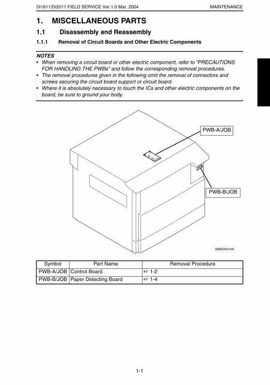
Di1611/Di2011 FIELD SERVICE Ver.1.0 Mar. 2004 MAINTENANCE
1. MISCELLANEOUS PARTS1.1 Disassembly and Reassembly1.1.1 Removal of Circuit Boards and Other Electric Components
NOTES• When removing a circuit board or other electric component, refer to “PRECAUTIONS
FOR HANDLING THE PWBs” and follow the corresponding removal procedures.• The removal procedures given in the following omit the removal of connectors and
screws securing the circuit board support or circuit board.• Where it is absolutely necessary to touch the ICs and other electric components on the
board, be sure to ground your body.
Symbol Part Name Removal Procedure
PWB-A/JOB Control Board ☞ 1-2
PWB-B/JOB Paper Detecting Board ☞ 1-4
4689D501AA
PWB-A/JOB
PWB-B/JOB
1-1
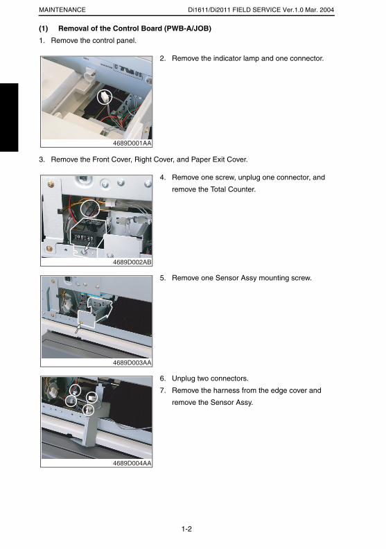
Di1611/Di2011 FIELD SERVICE Ver.1.0 Mar. 2004MAINTENANCE
(1) Removal of the Control Board (PWB-A/JOB)
1. Remove the control panel.
3. Remove the Front Cover, Right Cover, and Paper Exit Cover.
2. Remove the indicator lamp and one connector.
4689D001AA
4. Remove one screw, unplug one connector, and
remove the Total Counter.
4689D002AB
5. Remove one Sensor Assy mounting screw.
4689D003AA
6. Unplug two connectors.
7. Remove the harness from the edge cover and
remove the Sensor Assy.
4689D004AA
1-2
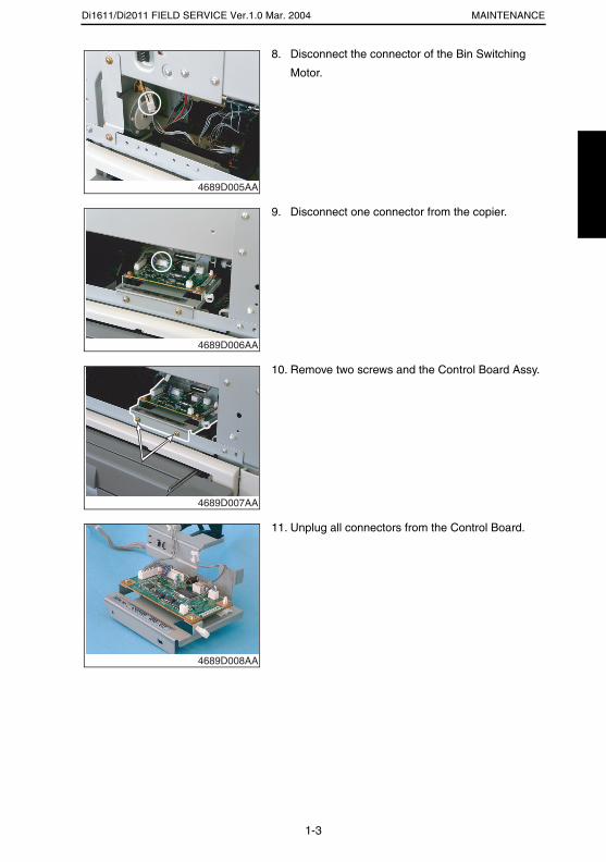
Di1611/Di2011 FIELD SERVICE Ver.1.0 Mar. 2004 MAINTENANCE
8. Disconnect the connector of the Bin Switching
Motor.
4689D005AA
9. Disconnect one connector from the copier.
4689D006AA
10. Remove two screws and the Control Board Assy.
4689D007AA
11. Unplug all connectors from the Control Board.
4689D008AA
1-3
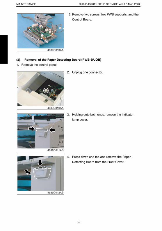
Di1611/Di2011 FIELD SERVICE Ver.1.0 Mar. 2004MAINTENANCE
(2) Removal of the Paper Detecting Board (PWB-B/JOB)
1. Remove the control panel.
12. Remove two screws, two PWB supports, and the
Control Board.
4689D009AA
2. Unplug one connector.
4689D010AA
3. Holding onto both ends, remove the indicator
lamp cover.
4689D011AB
4. Press down one tab and remove the Paper
Detecting Board from the Front Cover.
4689D012AB
1-4
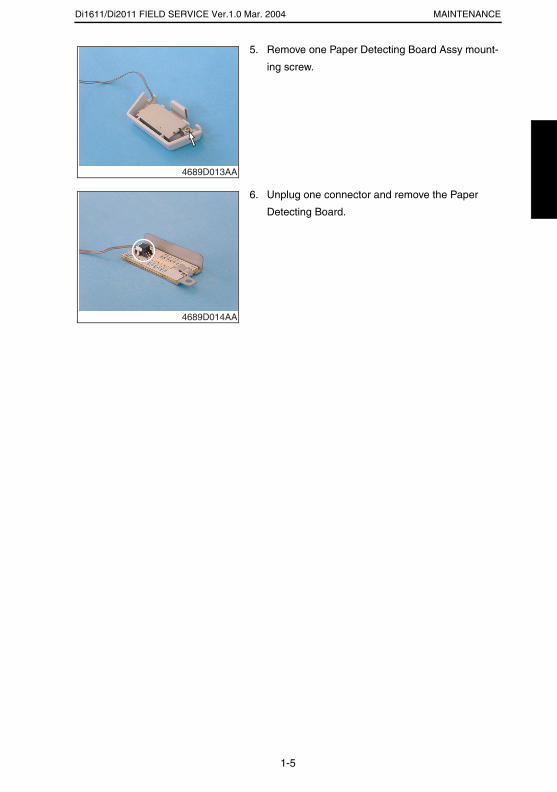
Di1611/Di2011 FIELD SERVICE Ver.1.0 Mar. 2004 MAINTENANCE
5. Remove one Paper Detecting Board Assy mount-
ing screw.
4689D013AA
6. Unplug one connector and remove the Paper
Detecting Board.
4689D014AA
1-5

TROUBLESHOOTING
19971

Di1611/Di2011 FIELD SERVICE Ver.1.0 Mar. 2004 TROUBLESHOOTING
1. INTRODUCTION
• Information required for troubleshooting and steps that must be performed are described
in this chapter.
1.1 Electrical Components Check Procedure• If a paper misfeed or malfunction occurs, perform the following operations to check the
condition of the electrical components.
1.1.1 Sensor
Step Check Result Action
1 Does the input signal of the control board change when the sensor light is interrupted? (H → L, L → H)
NO Replace the sensor.
YES Replace the control board.
4025T520AA
4025T521AA
2-1
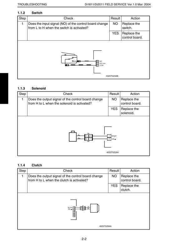
Di1611/Di2011 FIELD SERVICE Ver.1.0 Mar. 2004TROUBLESHOOTING
1.1.2 Switch
1.1.3 Solenoid
1.1.4 Clutch
Step Check Result Action
1 Does the input signal (NO) of the control board change from L to H when the switch is activated?
NO Replace the switch.
YES Replace the control board.
Step Check Result Action
1 Does the output signal of the control board change from H to L when the solenoid is activated?
NO Replace the control board.
YES Replace the solenoid.
Step Check Result Action
1 Does the output signal of the control board change from H to L when the clutch is activated?
NO Replace the control board.
YES Replace the clutch.
Not UseCOM
NO
4025T523AB
12
212
1
4025T522AA
4025T528AA
2-2
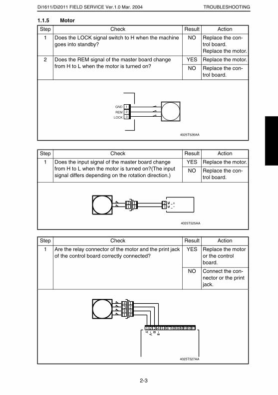
Di1611/Di2011 FIELD SERVICE Ver.1.0 Mar. 2004 TROUBLESHOOTING
1.1.5 Motor
Step Check Result Action
1 Does the LOCK signal switch to H when the machine goes into standby?
NO Replace the con-trol board. Replace the motor.
2 Does the REM signal of the master board change from H to L when the motor is turned on?
YES Replace the motor.
NO Replace the con-trol board.
Step Check Result Action
1 Does the input signal of the master board change from H to L when the motor is turned on?(The input signal differs depending on the rotation direction.)
YES Replace the motor.
NO Replace the con-trol board.
Step Check Result Action
1 Are the relay connector of the motor and the print jack of the control board correctly connected?
YES Replace the motor or the control board.
NO Connect the con-nector or the print jack.
GND
REM
LOCK
2
1
3
4025T526AA
4025T525AA
4025T527AA
2-3

Di1611/Di2011 FIELD SERVICE Ver.1.0 Mar. 2004TROUBLESHOOTING
2. MISFEEDS2.1 Initial Checks• When a paper misfeed occurs, first perform the following initial checks.
Check Item Action
Does paper meet product specifications? Replace paper.
Is the paper curled, wavy, or damp? Replace paper.Instruct the user on the correct paper storage procedures.
Is a foreign object present along the paper path, or is the paper path deformed or worn?
Clean or change the paper path.
Are the Paper Separator Fingers dirty, deformed, or worn?
Clean or replace the defective Paper Separator Finger.
Are rolls/rollers dirty, deformed, or worn? Clean or replace the defective roll/roller.
Are the Edge Guide and Trailing Edge Stop at the correct position to accommodate the paper?
Set as necessary.
Are the actuators operational and checked for correct operation?
Correct or replace the defective actua-tor.
2-4
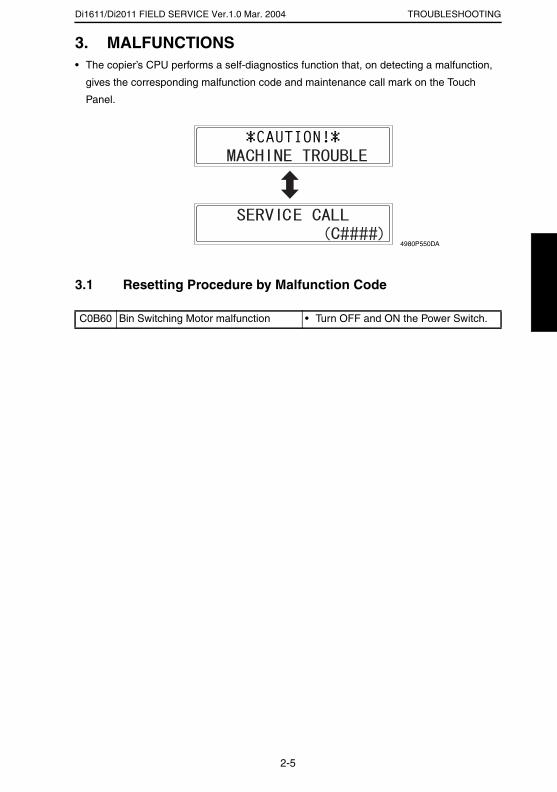
Di1611/Di2011 FIELD SERVICE Ver.1.0 Mar. 2004 TROUBLESHOOTING
3. MALFUNCTIONS• The copier’s CPU performs a self-diagnostics function that, on detecting a malfunction,
gives the corresponding malfunction code and maintenance call mark on the Touch
Panel.
3.1 Resetting Procedure by Malfunction Code
C0B60 Bin Switching Motor malfunction • Turn OFF and ON the Power Switch.
4980P550DA
2-5
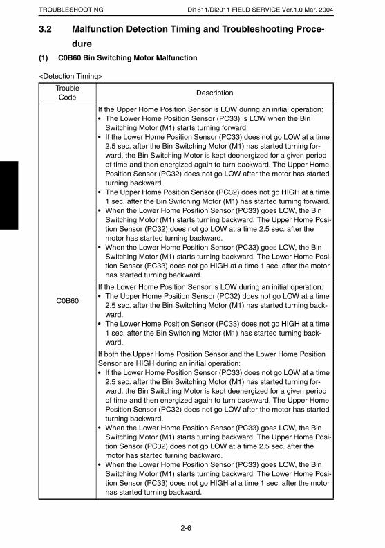
Di1611/Di2011 FIELD SERVICE Ver.1.0 Mar. 2004TROUBLESHOOTING
3.2 Malfunction Detection Timing and Troubleshooting Proce-
dure(1) C0B60 Bin Switching Motor Malfunction
<Detection Timing>
TroubleCode
Description
C0B60
If the Upper Home Position Sensor is LOW during an initial operation:• The Lower Home Position Sensor (PC33) is LOW when the Bin
Switching Motor (M1) starts turning forward.• If the Lower Home Position Sensor (PC33) does not go LOW at a time
2.5 sec. after the Bin Switching Motor (M1) has started turning for-ward, the Bin Switching Motor is kept deenergized for a given period of time and then energized again to turn backward. The Upper Home Position Sensor (PC32) does not go LOW after the motor has started turning backward.
• The Upper Home Position Sensor (PC32) does not go HIGH at a time 1 sec. after the Bin Switching Motor (M1) has started turning forward.
• When the Lower Home Position Sensor (PC33) goes LOW, the Bin Switching Motor (M1) starts turning backward. The Upper Home Posi-tion Sensor (PC32) does not go LOW at a time 2.5 sec. after the motor has started turning backward.
• When the Lower Home Position Sensor (PC33) goes LOW, the Bin Switching Motor (M1) starts turning backward. The Lower Home Posi-tion Sensor (PC33) does not go HIGH at a time 1 sec. after the motor has started turning backward.
If the Lower Home Position Sensor is LOW during an initial operation:• The Upper Home Position Sensor (PC32) does not go LOW at a time
2.5 sec. after the Bin Switching Motor (M1) has started turning back-ward.
• The Lower Home Position Sensor (PC33) does not go HIGH at a time 1 sec. after the Bin Switching Motor (M1) has started turning back-ward.
If both the Upper Home Position Sensor and the Lower Home Position Sensor are HIGH during an initial operation:• If the Lower Home Position Sensor (PC33) does not go LOW at a time
2.5 sec. after the Bin Switching Motor (M1) has started turning for-ward, the Bin Switching Motor is kept deenergized for a given period of time and then energized again to turn backward. The Upper Home Position Sensor (PC32) does not go LOW after the motor has started turning backward.
• When the Lower Home Position Sensor (PC33) goes LOW, the Bin Switching Motor (M1) starts turning backward. The Upper Home Posi-tion Sensor (PC32) does not go LOW at a time 2.5 sec. after the motor has started turning backward.
• When the Lower Home Position Sensor (PC33) goes LOW, the Bin Switching Motor (M1) starts turning backward. The Lower Home Posi-tion Sensor (PC33) does not go HIGH at a time 1 sec. after the motor has started turning backward.
2-6
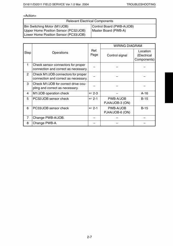
Di1611/Di2011 FIELD SERVICE Ver.1.0 Mar. 2004 TROUBLESHOOTING
<Action>
Relevant Electrical Components
Bin Switching Motor (M1/JOB)Upper Home Position Sensor (PC32/JOB)Lower Home Position Sensor (PC33/JOB)
Control Board (PWB-A/JOB)Master Board (PWB-A)
Step OperationsRef. Page
WIRING DIAGRAM
Control signalLocation
(Electrical Components)
1 Check sensor connectors for proper connection and correct as necessary.
– – –
2 Check M1/JOB connectors for proper connection and correct as necessary.
– – –
3 Check M1/JOB for correct drive cou-pling and correct as necessary.
– – –
4 M1/JOB operation check ☞ 2-3 – A-16
5 PC32/JOB sensor check ☞ 2-1 PWB-A/JOB PJ4A/JOB-3 (ON)
B-15
6 PC33/JOB sensor check ☞ 2-1 PWB-A/JOB PJ4A/JOB-6 (ON)
B-15
7 Change PWB-A/JOB. – – –
8 Change PWB-A. – – –
2-7

SERVICE MANUAL
2004.3Ver. 1.0
FIELD SERVICE
OT-103

INDEX
TROUBLESHOOTING
MAINTENANCE
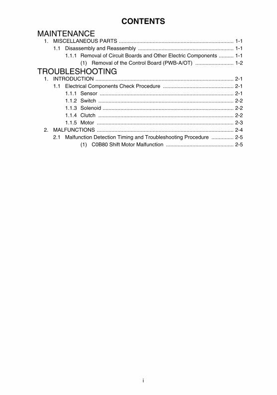
i
CONTENTS
MAINTENANCE1. MISCELLANEOUS PARTS .............................................................................. 1-1
1.1 Disassembly and Reassembly ................................................................. 1-11.1.1 Removal of Circuit Boards and Other Electric Components .......... 1-1
(1) Removal of the Control Board (PWB-A/OT) .......................... 1-2
TROUBLESHOOTING1. INTRODUCTION .............................................................................................. 2-1
1.1 Electrical Components Check Procedure ................................................ 2-11.1.1 Sensor ........................................................................................... 2-11.1.2 Switch ............................................................................................ 2-21.1.3 Solenoid ......................................................................................... 2-21.1.4 Clutch ............................................................................................ 2-21.1.5 Motor ............................................................................................. 2-3
2. MALFUNCTIONS ............................................................................................. 2-42.1 Malfunction Detection Timing and Troubleshooting Procedure ............... 2-5
(1) C0B80 Shift Motor Malfunction .............................................. 2-5

MAINTENANCE
19971
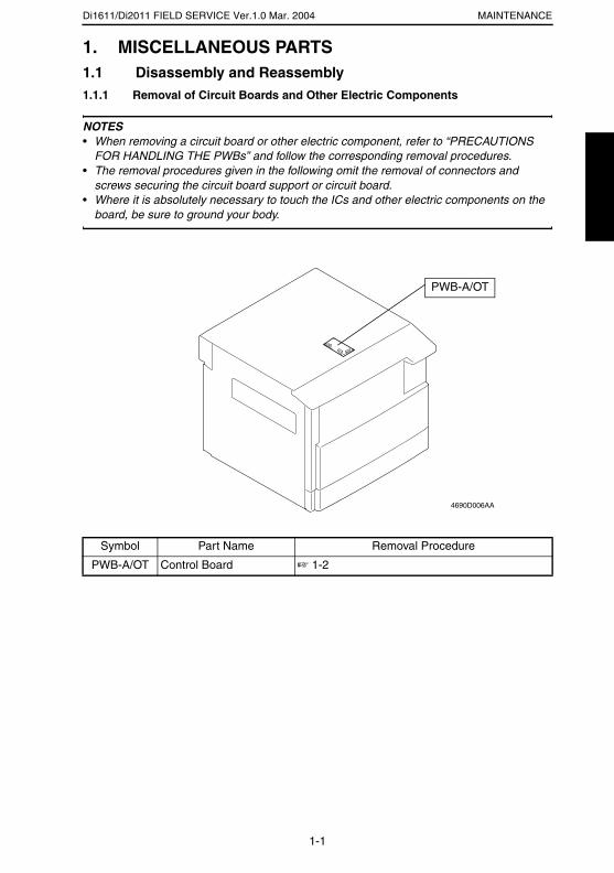
Di1611/Di2011 FIELD SERVICE Ver.1.0 Mar. 2004 MAINTENANCE
1. MISCELLANEOUS PARTS1.1 Disassembly and Reassembly1.1.1 Removal of Circuit Boards and Other Electric Components
NOTES• When removing a circuit board or other electric component, refer to “PRECAUTIONS
FOR HANDLING THE PWBs” and follow the corresponding removal procedures.• The removal procedures given in the following omit the removal of connectors and
screws securing the circuit board support or circuit board.• Where it is absolutely necessary to touch the ICs and other electric components on the
board, be sure to ground your body.
Symbol Part Name Removal Procedure
PWB-A/OT Control Board ☞ 1-2
PWB-A/OT
4690D006AA
1-1
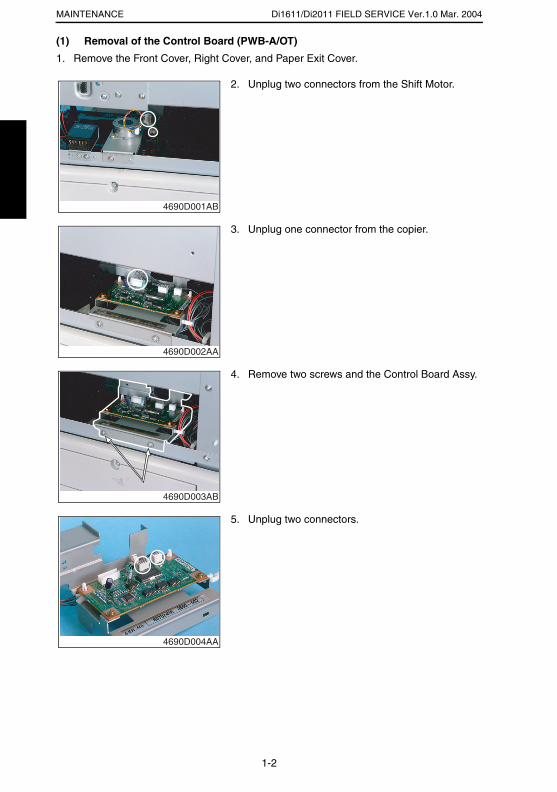
Di1611/Di2011 FIELD SERVICE Ver.1.0 Mar. 2004MAINTENANCE
(1) Removal of the Control Board (PWB-A/OT)
1. Remove the Front Cover, Right Cover, and Paper Exit Cover.
2. Unplug two connectors from the Shift Motor.
4690D001AB
3. Unplug one connector from the copier.
4690D002AA
4. Remove two screws and the Control Board Assy.
4690D003AB
5. Unplug two connectors.
4690D004AA
1-2
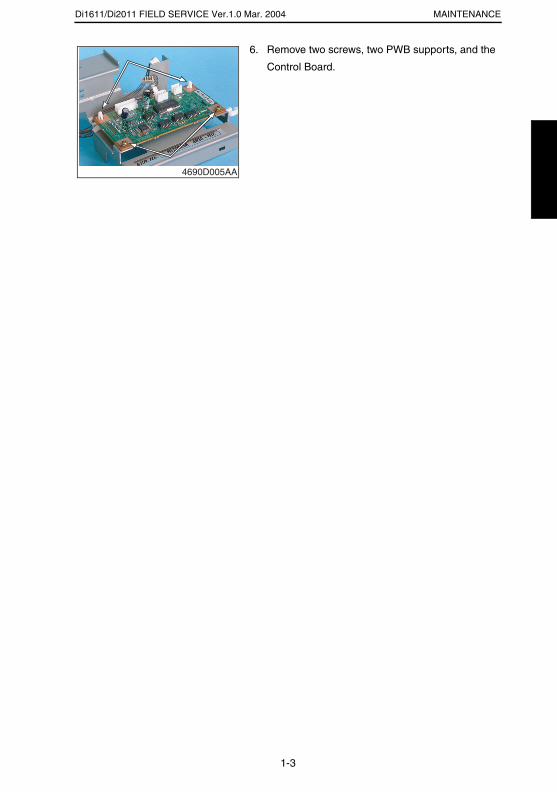
Di1611/Di2011 FIELD SERVICE Ver.1.0 Mar. 2004 MAINTENANCE
6. Remove two screws, two PWB supports, and the
Control Board.
4690D005AA
1-3

TROUBLESHOOTING
19971
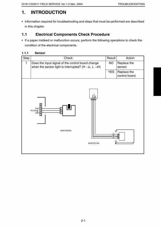
Di1611/Di2011 FIELD SERVICE Ver.1.0 Mar. 2004 TROUBLESHOOTING
1. INTRODUCTION
• Information required for troubleshooting and steps that must be performed are described
in this chapter.
1.1 Electrical Components Check Procedure• If a paper misfeed or malfunction occurs, perform the following operations to check the
condition of the electrical components.
1.1.1 Sensor
Step Check Result Action
1 Does the input signal of the control board change when the sensor light is interrupted? (H → L, L → H)
NO Replace the sensor.
YES Replace the control board.
4025T520AA
4025T521AA
2-1
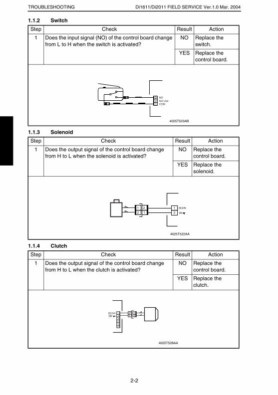
Di1611/Di2011 FIELD SERVICE Ver.1.0 Mar. 2004TROUBLESHOOTING
1.1.2 Switch
1.1.3 Solenoid
1.1.4 Clutch
Step Check Result Action
1 Does the input signal (NO) of the control board change from L to H when the switch is activated?
NO Replace the switch.
YES Replace the control board.
Step Check Result Action
1 Does the output signal of the control board change from H to L when the solenoid is activated?
NO Replace the control board.
YES Replace the solenoid.
Step Check Result Action
1 Does the output signal of the control board change from H to L when the clutch is activated?
NO Replace the control board.
YES Replace the clutch.
Not UseCOM
NO
4025T523AB
12
212
1
4025T522AA
4025T528AA
2-2

Di1611/Di2011 FIELD SERVICE Ver.1.0 Mar. 2004 TROUBLESHOOTING
1.1.5 Motor
Step Check Result Action
1 Does the LOCK signal switch to H when the machine goes into standby?
NO Replace the con-trol board. Replace the motor.
2 Does the REM signal of the master board change from H to L when the motor is turned on?
YES Replace the motor.
NO Replace the con-trol board.
Step Check Result Action
1 Does the input signal of the master board change from H to L when the motor is turned on?(The input signal differs depending on the rotation direction.)
YES Replace the motor.
NO Replace the con-trol board.
Step Check Result Action
1 Are the relay connector of the motor and the print jack of the control board correctly connected?
YES Replace the motor or the control board.
NO Connect the con-nector or the print jack.
GND
REM
LOCK
2
1
3
4025T526AA
4025T525AA
4025T527AA
2-3
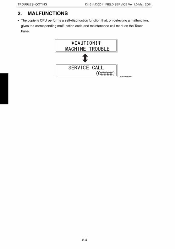
Di1611/Di2011 FIELD SERVICE Ver.1.0 Mar. 2004TROUBLESHOOTING
2. MALFUNCTIONS• The copier’s CPU performs a self-diagnostics function that, on detecting a malfunction,
gives the corresponding malfunction code and maintenance call mark on the Touch
Panel.
4980P550DA
2-4
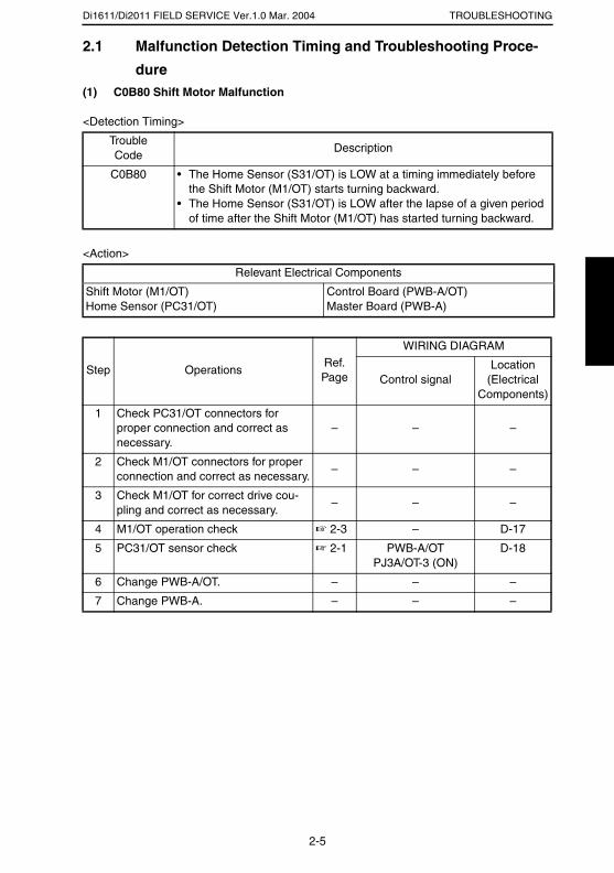
Di1611/Di2011 FIELD SERVICE Ver.1.0 Mar. 2004 TROUBLESHOOTING
2.1 Malfunction Detection Timing and Troubleshooting Proce-
dure(1) C0B80 Shift Motor Malfunction
<Detection Timing>
<Action>
TroubleCode
Description
C0B80 • The Home Sensor (S31/OT) is LOW at a timing immediately before the Shift Motor (M1/OT) starts turning backward.
• The Home Sensor (S31/OT) is LOW after the lapse of a given period of time after the Shift Motor (M1/OT) has started turning backward.
Relevant Electrical Components
Shift Motor (M1/OT)Home Sensor (PC31/OT)
Control Board (PWB-A/OT)Master Board (PWB-A)
Step OperationsRef. Page
WIRING DIAGRAM
Control signalLocation
(Electrical Components)
1 Check PC31/OT connectors for proper connection and correct as necessary.
– – –
2 Check M1/OT connectors for proper connection and correct as necessary.
– – –
3 Check M1/OT for correct drive cou-pling and correct as necessary.
– – –
4 M1/OT operation check ☞ 2-3 – D-17
5 PC31/OT sensor check ☞ 2-1 PWB-A/OT PJ3A/OT-3 (ON)
D-18
6 Change PWB-A/OT. – – –
7 Change PWB-A. – – –
2-5

SERVICE MANUAL
2004.3Ver. 1.0
FIELD SERVICE
NC-6

INDEX
DIS/REASSEMBLY,Updating the Firmware
ELECTRICAL
SETTING
TROUBLESHOOTING
i
CONTENTSELECTRICAL
1. SPECIFICATIONS ........................................................................................... 1-12. Data Flow Diagram .......................................................................................... 1-1
2-1 Data Flow Diagram for Network GDI Printing .......................................... 1-12-2 Electrical Components ............................................................................. 1-2
1 Network Interface Card .................................................................. 1-22 LED status display list ................................................................... 1-3
DIS/REASSEMBLY,Updating the Firmware
1. Updating the Firmware ..................................................................................... 2-12. DISASSEMBLY/REASSEMBLY ...................................................................... 2-4
2.1 Removal of the Network Interface Card ................................................... 2-4
SETTING1. UTILITY MODE ................................................................................................ 3-1
1-1 Utility Mode Function Tree ....................................................................... 3-11-2 Utility Mode Setting Procedure ................................................................. 3-3
1 Network setting .............................................................................. 3-42 E-mail setting 1 .............................................................................. 3-63 E-mail setting 2 .............................................................................. 3-84 Scan setting ................................................................................... 3-10
TROUBLESHOOTING1. TROUBLESHOOTING ..................................................................................... 4-1
1.1 Troubleshooting Procedure Overview ...................................................... 4-11.2 Troubleshooting Procedure Chart ............................................................ 4-11.3 Action Taken if Network Print Cannot be Done ........................................ 4-2

ELECTRICAL
19971
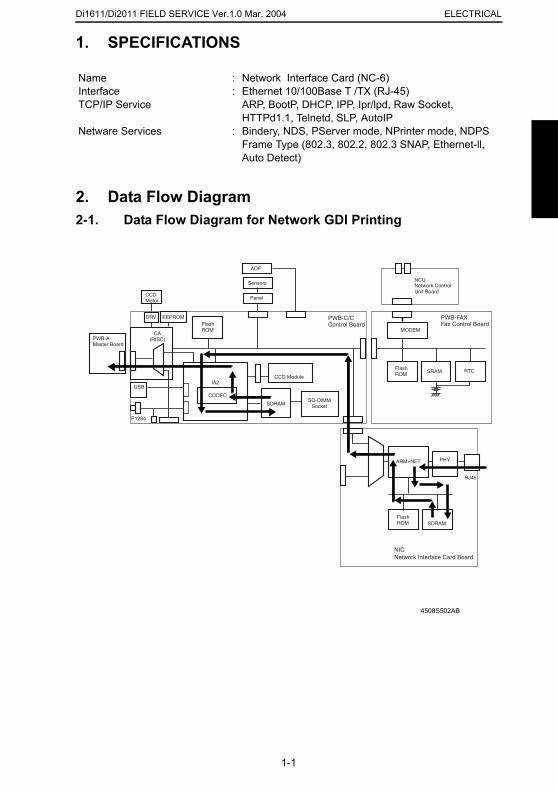
Di1611/Di2011 FIELD SERVICE Ver.1.0 Mar. 2004 ELECTRICAL
1. SPECIFICATIONS
2. Data Flow Diagram2-1. Data Flow Diagram for Network GDI Printing
NameInterfaceTCP/IP Service
Netware Services
::
:
Network Interface Card (NC-6)Ethernet 10/100Base T /TX (RJ-45) ARP, BootP, DHCP, IPP, Ipr/lpd, Raw Socket, HTTPd1.1, Telnetd, SLP, AutoIPBindery, NDS, PServer mode, NPrinter mode, NDPSFrame Type (802.3, 802.2, 802.3 SNAP, Ethernet-ll, Auto Detect)
4508S502AB
CCDMotor
DRV EEPROM
CA(RISC)PWB-A
Master Board
USB
P1284
FlashROM
FlashROM
ADF
Sensors
Panel
IA2
CODEC
CCD Module
SDRAMSO-DIMM
Socket
SDRAM
PHYARM+NET
SRAM RTC
MODEM
NCU
RJ45
Network ControlUnit Board
NICNetwork Interface Card Board
PWB-C/CControl Board
FlashROM
PWB-FAXFax Control Board
1-1
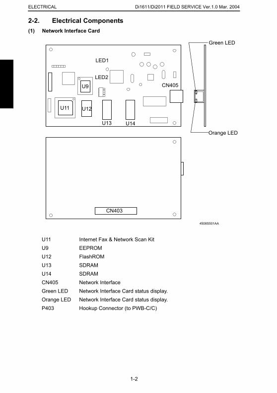
Di1611/Di2011 FIELD SERVICE Ver.1.0 Mar. 2004ELECTRICAL
2-2. Electrical Components(1) Network Interface Card
U11 Internet Fax & Network Scan KitU9 EEPROMU12 FlashROMU13 SDRAMU14 SDRAMCN405 Network InterfaceGreen LED Network Interface Card status display.Orange LED Network Interface Card status display.P403 Hookup Connector (to PWB-C/C)
4508S501AA
U11
LED1
LED2
CN403
CN405
Orange LED
Green LED
U12
U9
U13 U14
1-2

Di1611/Di2011 FIELD SERVICE Ver.1.0 Mar. 2004 ELECTRICAL
(2) LED status display list
LEDs Status
Green LED (Green) ON
This is lit when the network cable is connected correctly. If this LED is not lit, check the connection again, even if the copier appears to be connected correctly. If this LED is not lit when both ends are connected correctly, the network cable may be damaged.
Orange LED (Orange) ON This LED blinks when data is being transfered.
1-3

Di1611/Di2011 FIELD SERVICE Ver.1.0 Mar. 2004ELECTRICAL
1-4

DIS/REASSEMBLY,Updating the Firmware
19971
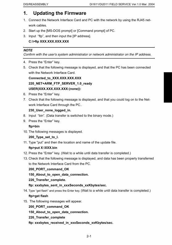
Di1611/Di2011 FIELD SERVICE Ver.1.0 Mar. 2004DIS/REASSEMBLY
1. Updating the Firmware1. Connect the Network Interface Card and PC with the network by using the RJ45 net-
work cables. 2. Start up the [MS-DOS prompt] or [Command prompt] of PC.3. Input “ftp”, and then input the [IP address].
C:\>ftp XXX.XXX.XXX.XXX
NOTEConfirm with the user's system administrator or network administrator on the IP address.
4. Press the “Enter” key.5. Check that the following message is displayed, and that the PC has been connected
with the Network Interface Card. Connected_to_XXX.XXX.XXX.XXX220_NET+ARM_FTP_SERVER_1.0_readyUSER(XXX.XXX.XXX.XXX:(none)):
6. Press the “Enter” key.7. Check that the following message is displayed, and that you could log on to the Net-
work Interface Card through the PC..230_User_none_logged_in.
8. Input “bin”. (Data transfer is switched to the binary mode.)9. Press the “Enter” key.
ftp>bin10. The following messages is displayed.
200_Type_set_to_I.11. Type "put” and then the location and name of the update file.
ftp>put X:\XXX.bin12. Press the “Enter” key. (Wait to a while until data transfer is completed.)13. Check that the following message is displayed, and data has been properly transferred
to the Network Interface Card from the PC.200_PORT_command_OK150_About_to_open_data_connection.226_Transfer_complete.ftp: xxxbytes_sent_in_xxxSeconds_xxKbytes/sec.
14. Type “get flash” and press the Enter key. (Wait to a while until data transfer is completed.)ftp>get flash
15. The following messages will appear.200_PORT_command_OK150_About_to_open_data_connection.226_Transfer_completeftp: xxxbytes_received_in_xxxSeconds_xxKbytes/sec.
2-1
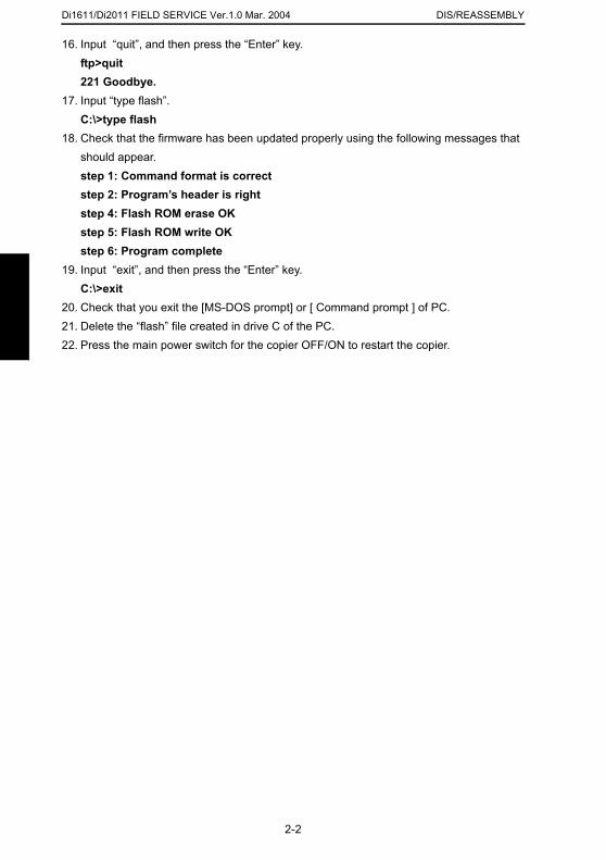
Di1611/Di2011 FIELD SERVICE Ver.1.0 Mar. 2004 DIS/REASSEMBLY
16. Input “quit”, and then press the “Enter” key.ftp>quit221 Goodbye.
17. Input “type flash”.C:\>type flash
18. Check that the firmware has been updated properly using the following messages that should appear.step 1: Command format is correctstep 2: Program’s header is rightstep 4: Flash ROM erase OKstep 5: Flash ROM write OKstep 6: Program complete
19. Input “exit”, and then press the “Enter” key.C:\>exit
20. Check that you exit the [MS-DOS prompt] or [ Command prompt ] of PC.21. Delete the “flash” file created in drive C of the PC.22. Press the main power switch for the copier OFF/ON to restart the copier.
2-2
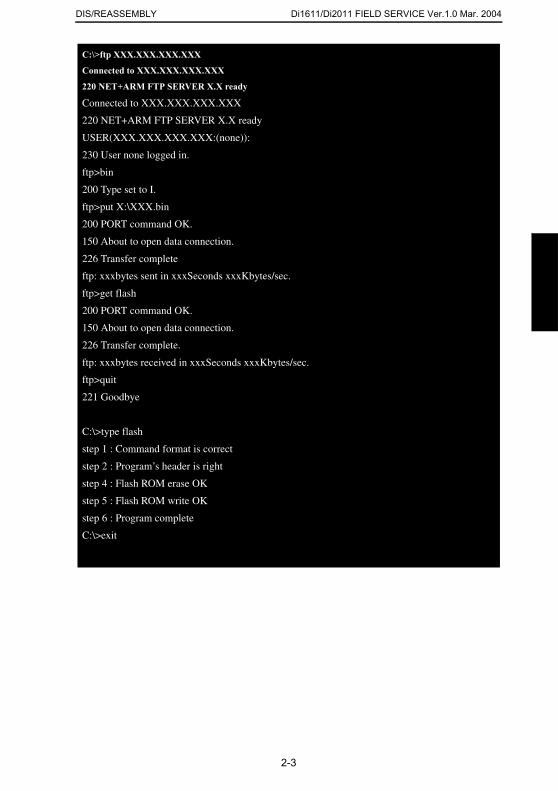
Di1611/Di2011 FIELD SERVICE Ver.1.0 Mar. 2004DIS/REASSEMBLY
C:\>ftp XXX.XXX.XXX.XXX
Connected to XXX.XXX.XXX.XXX
220 NET+ARM FTP SERVER X.X ready
Connected to XXX.XXX.XXX.XXX
220 NET+ARM FTP SERVER X.X ready
USER(XXX.XXX.XXX.XXX:(none)):
230 User none logged in.
ftp>bin
200 Type set to I.
ftp>put X:\XXX.bin
200 PORT command OK.
150 About to open data connection.
226 Transfer complete
ftp: xxxbytes sent in xxxSeconds xxxKbytes/sec.
ftp>get flash
200 PORT command OK.
150 About to open data connection.
226 Transfer complete.
ftp: xxxbytes received in xxxSeconds xxxKbytes/sec.
ftp>quit
221 Goodbye
C:\>type flash
step 1 : Command format is correct
step 2 : Program’s header is right
step 4 : Flash ROM erase OK
step 5 : Flash ROM write OK
step 6 : Program complete
C:\>exit
2-3
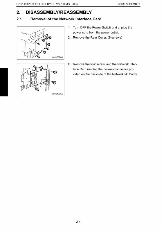
Di1611/Di2011 FIELD SERVICE Ver.1.0 Mar. 2004 DIS/REASSEMBLY
2. DISASSEMBLY/REASSEMBLY2.1 Removal of the Network Interface Card
1. Turn OFF the Power Switch and unplug the power cord from the power outlet.
2. Remove the Rear Cover. (9 screws)
4048U006AB
C. Remove the four screw, and the Network Inter-face Card (unplug the hookup connector pro-vided on the backside of the Network I/F Card).
4506U153AA
2-4

SETTING
19971
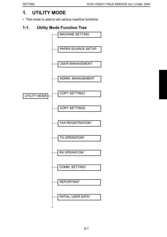
Di1611/Di2011 FIELD SERVICE Ver.1.0 Mar. 2004SETTING
1. UTILITY MODE• This mode is used to set various machine functions.
1-1. Utility Mode Function Tree
UTILITY MODE
MACHINE SETTING
PAPER SOURCE SETUP
COPY SETTING1
ADMIN. MANAGEMENT
FAX REGISTRATION*
TX OPERATION*
~
USER MANAGEMENT
RX OPERATION*
COMM. SETTING*
REPORTING*
INITIAL USER DATA*
COPY SETTING2
2-1
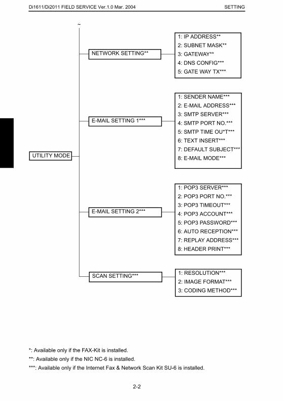
Di1611/Di2011 FIELD SERVICE Ver.1.0 Mar. 2004 SETTING
*: Available only if the FAX-Kit is installed.**: Available only if the NIC NC-6 is installed.***: Available only if the Internet Fax & Network Scan Kit SU-6 is installed.
UTILITY MODE
NETWORK SETTING**
1: IP ADDRESS**2: SUBNET MASK**3: GATEWAY**4: DNS CONFIG***5: GATE WAY TX***
~
E-MAIL SETTING 1***
1: SENDER NAME***2: E-MAIL ADDRESS***3: SMTP SERVER***4: SMTP PORT NO.***5: SMTP TIME OU*T***6: TEXT INSERT***7: DEFAULT SUBJECT***8: E-MAIL MODE***
E-MAIL SETTING 2***
1: POP3 SERVER***2: POP3 PORT NO.***3: POP3 TIMEOUT***4: POP3 ACCOUNT***5: POP3 PASSWORD***6: AUTO RECEPTION***7: REPLAY ADDRESS***8: HEADER PRINT***
1: RESOLUTION***2: IMAGE FORMAT***3: CODING METHOD***
SCAN SETTING***
2-2
Di1611/Di2011 FIELD SERVICE Ver.1.0 Mar. 2004SETTING
1-2. Utility Mode Setting Procedure<Procedure>1. Press the Utility key.2. The first Utility mode screen appears.
<Exiting Procedure>• Press the Panel Reset key.
<Changing the Settings for Utility Mode Functions>1. Press the ▲/ ▼ key, < / > key or the 10-Key Pad to select the desired function.2. Press the ▲/ ▼ key, < / > key or the 10-Key Pad to select the desired setting.3. Press the Yes key to apply the setting.4. To return to the previous screen, press the No/ C key.
2-3
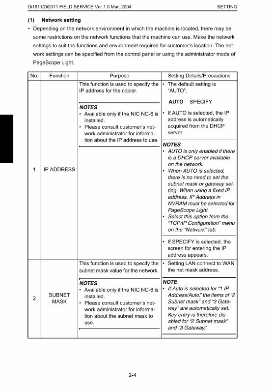
Di1611/Di2011 FIELD SERVICE Ver.1.0 Mar. 2004 SETTING
(1) Network setting• Depending on the network environment in which the machine is located, there may be
some restrictions on the network functions that the machine can use. Make the network settings to suit the functions and environment required for customer’s location. The net-work settings can be specified from the control panel or using the administrator mode of PageScope Light.
No. Function Purpose Setting Details/Precautions
1 IP ADDRESS
This function is used to specify the IP address for the copier.
NOTES• Available only if the NIC NC-6 is
installed.• Please consult customer’s net-
work administrator for informa-tion about the IP address to use.
• The default setting is “AUTO”.
AUTO SPECIFY
• If AUTO is selected, the IP address is automatically acquired from the DHCP server.
NOTES• AUTO is only enabled if there
is a DHCP server available on the network.
• When AUTO is selected, there is no need to set the subnet mask or gateway set-ting. When using a fixed IP address, IP Address in NVRAM must be selected for PageScope Light.
• Select this option from the “TCP/IP Configuration” menu on the “Network” tab.
• If SPECIFY is selected, the screen for entering the IP address appears.
2 SUBNET MASK
This function is used to specify the subnet mask value for the network.
NOTES• Available only if the NIC NC-6 is
installed.• Please consult customer’s net-
work administrator for informa-tion about the subnet mask to use.
• Setting LAN connect to WAN the net mask address.
NOTE• If Auto is selected for “1 IP
Address/Auto,” the items of “2 Subnet mask” and “3 Gate-way” are automatically set. Key entry is therefore dis-abled for “2 Subnet mask” and “3 Gateway.”
2-4
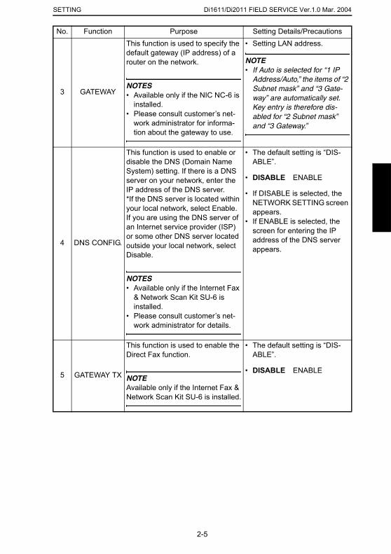
Di1611/Di2011 FIELD SERVICE Ver.1.0 Mar. 2004SETTING
3 GATEWAY
This function is used to specify the default gateway (IP address) of a router on the network.
NOTES• Available only if the NIC NC-6 is
installed.• Please consult customer’s net-
work administrator for informa-tion about the gateway to use.
• Setting LAN address.
NOTE• If Auto is selected for “1 IP
Address/Auto,” the items of “2 Subnet mask” and “3 Gate-way” are automatically set. Key entry is therefore dis-abled for “2 Subnet mask” and “3 Gateway.”
4 DNS CONFIG.
This function is used to enable or disable the DNS (Domain Name System) setting. If there is a DNS server on your network, enter the IP address of the DNS server. *If the DNS server is located within your local network, select Enable. If you are using the DNS server of an Internet service provider (ISP) or some other DNS server located outside your local network, select Disable.
NOTES• Available only if the Internet Fax
& Network Scan Kit SU-6 is installed.
• Please consult customer’s net-work administrator for details.
• The default setting is “DIS-ABLE”.
• DISABLE ENABLE
• If DISABLE is selected, the NETWORK SETTING screen appears.
• If ENABLE is selected, the screen for entering the IP address of the DNS server appears.
5 GATEWAY TX
This function is used to enable the Direct Fax function.
NOTEAvailable only if the Internet Fax & Network Scan Kit SU-6 is installed.
• The default setting is “DIS-ABLE”.
• DISABLE ENABLE
No. Function Purpose Setting Details/Precautions
2-5
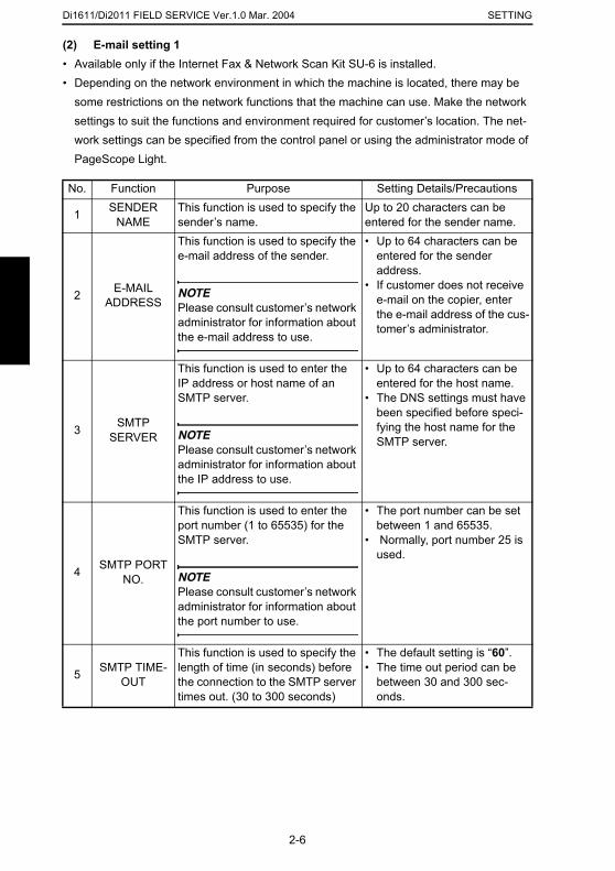
Di1611/Di2011 FIELD SERVICE Ver.1.0 Mar. 2004 SETTING
(2) E-mail setting 1• Available only if the Internet Fax & Network Scan Kit SU-6 is installed.• Depending on the network environment in which the machine is located, there may be
some restrictions on the network functions that the machine can use. Make the network settings to suit the functions and environment required for customer’s location. The net-work settings can be specified from the control panel or using the administrator mode of PageScope Light.
No. Function Purpose Setting Details/Precautions
1 SENDER NAME
This function is used to specify the sender’s name.
Up to 20 characters can be entered for the sender name.
2 E-MAIL ADDRESS
This function is used to specify the e-mail address of the sender.
NOTEPlease consult customer’s network administrator for information about the e-mail address to use.
• Up to 64 characters can be entered for the sender address.
• If customer does not receive e-mail on the copier, enter the e-mail address of the cus-tomer’s administrator.
3 SMTP SERVER
This function is used to enter the IP address or host name of an SMTP server.
NOTEPlease consult customer’s network administrator for information about the IP address to use.
• Up to 64 characters can be entered for the host name.
• The DNS settings must have been specified before speci-fying the host name for the SMTP server.
4 SMTP PORT NO.
This function is used to enter the port number (1 to 65535) for the SMTP server.
NOTEPlease consult customer’s network administrator for information about the port number to use.
• The port number can be set between 1 and 65535.
• Normally, port number 25 is used.
5 SMTP TIME-OUT
This function is used to specify the length of time (in seconds) before the connection to the SMTP server times out. (30 to 300 seconds)
• The default setting is “60”.• The time out period can be
between 30 and 300 sec-onds.
2-6
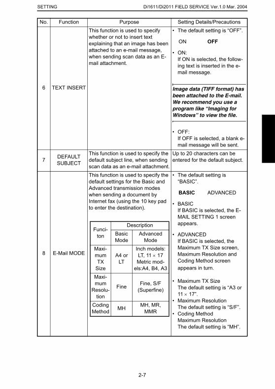
Di1611/Di2011 FIELD SERVICE Ver.1.0 Mar. 2004SETTING
6 TEXT INSERT
This function is used to specify whether or not to insert text explaining that an image has been attached to an e-mail message, when sending scan data as an E-mail attachment.
• The default setting is “OFF”.
ON OFF
• ON:If ON is selected, the follow-ing text is inserted in the e-mail message.
Image data (TIFF format) has been attached to the E-mail. We recommend you use a program like “Imaging for Windows” to view the file.
• OFF: If OFF is selected, a blank e-mail message will be sent.
7 DEFAULT SUBJECT
This function is used to specify the default subject line, when sending scan data as an e-mail attachment.
Up to 20 characters can be entered for the default subject.
8 E-Mail MODE
This function is used to specify the default settings for the Basic and Advanced transmission modes when sending a document by Internet fax (using the 10 key pad to enter the destination).
• The default setting is “BASIC”.
BASIC ADVANCED
• BASICIf BASIC is selected, the E-MAIL SETTING 1 screen appears.
• ADVANCEDIf BASIC is selected, the Maximum TX Size screen, Maximum Resolution and Coding Method screen appears in turn.
• Maximum TX SizeThe default setting is “A3 or 11 × 17”.
• Maximum ResolutionThe default setting is “S/F”.
• Coding MethodMaximum ResolutionThe default setting is “MH”.
No. Function Purpose Setting Details/Precautions
Funci-ton
DescriptionBasic Mode
Advanced Mode
Maxi-mum TX
Size
A4 or LT
Inch models: LT, 11 × 17Metric mod-
els:A4, B4, A3Maxi-mum
Resolu-tion
Fine Fine, S/F (Superfine)
Coding Method MH MH, MR,
MMR
2-7

Di1611/Di2011 FIELD SERVICE Ver.1.0 Mar. 2004 SETTING
(3) E-mail setting 2• Available only if the Internet Fax & Network Scan Kit SU-6 is installed.• Depending on the network environment in which the machine is located, there may be
some restrictions on the network functions that the machine can use. Make the network settings to suit the functions and environment required for customer’s location. The net-work settings can be specified from the control panel or using the administrator mode of PageScope Light.
No. Function Purpose Setting Details/Precautions
1 POP3 SERVER
This function is used to enter the IP address or host name of an POP3 server.
NOTEPlease consult customer’s network administrator for information about the IP address to use.
• Up to 64 characters can be entered for the host name.
• The DNS settings must have been specified before speci-fying the host name for the POP3 server.
2 POP3 PORT NO.
This function is used to enter the port number (1 to 65535) for the POP3 server.
NOTEPlease consult customer’s network administrator for information about the port number to use.
• The port number can be set between 1 and 65535.
• Normally, port number 110 is used.
3 POP3 TIME-OUT
This function is used to specify the length of time (in seconds) before the connection to the POP3 server times out. (30 to 300 seconds)
• The default setting is “60”.• The time out period can be
between 30 and 300 sec-onds.
4 POP3 ACCOUNT
This function is used to enter the account name used to log on to the POP3 server.
NOTEPlease consult customer’s network administrator for information about the account name to use.
Up to 64 characters can be entered for the account name.
2-8
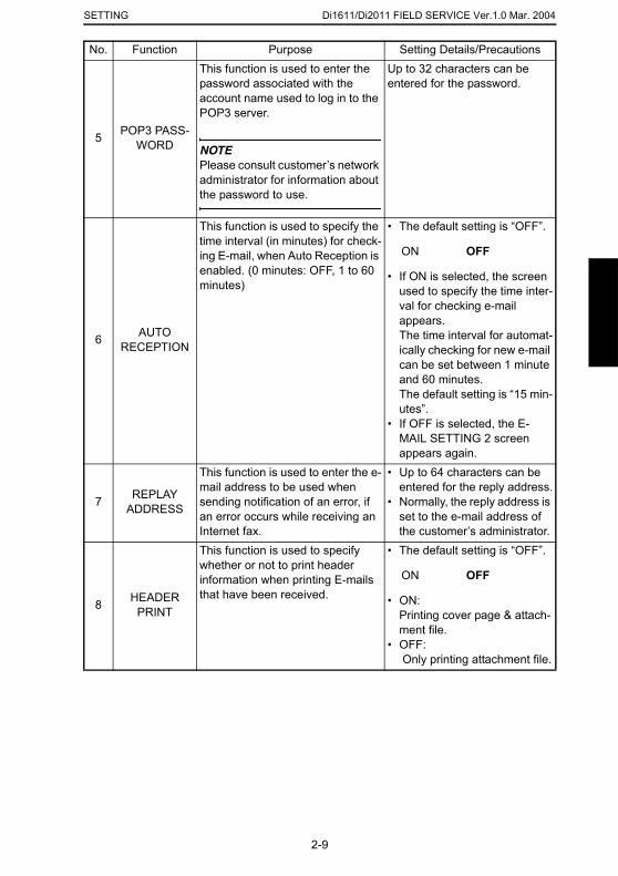
Di1611/Di2011 FIELD SERVICE Ver.1.0 Mar. 2004SETTING
5 POP3 PASS-WORD
This function is used to enter the password associated with the account name used to log in to the POP3 server.
NOTEPlease consult customer’s network administrator for information about the password to use.
Up to 32 characters can be entered for the password.
6 AUTO RECEPTION
This function is used to specify the time interval (in minutes) for check-ing E-mail, when Auto Reception is enabled. (0 minutes: OFF, 1 to 60 minutes)
• The default setting is “OFF”.
ON OFF
• If ON is selected, the screen used to specify the time inter-val for checking e-mail appears. The time interval for automat-ically checking for new e-mail can be set between 1 minute and 60 minutes. The default setting is “15 min-utes”.
• If OFF is selected, the E-MAIL SETTING 2 screen appears again.
7 REPLAY ADDRESS
This function is used to enter the e-mail address to be used when sending notification of an error, if an error occurs while receiving an Internet fax.
• Up to 64 characters can be entered for the reply address.
• Normally, the reply address is set to the e-mail address of the customer’s administrator.
8 HEADER PRINT
This function is used to specify whether or not to print header information when printing E-mails that have been received.
• The default setting is “OFF”.
ON OFF
• ON: Printing cover page & attach-ment file.
• OFF: Only printing attachment file.
No. Function Purpose Setting Details/Precautions
2-9
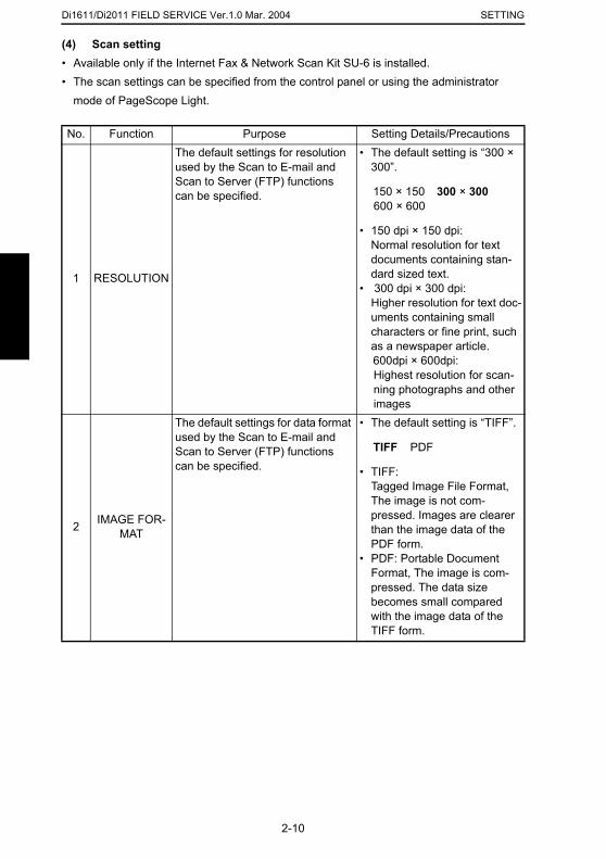
Di1611/Di2011 FIELD SERVICE Ver.1.0 Mar. 2004 SETTING
(4) Scan setting• Available only if the Internet Fax & Network Scan Kit SU-6 is installed.• The scan settings can be specified from the control panel or using the administrator
mode of PageScope Light.
No. Function Purpose Setting Details/Precautions
1 RESOLUTION
The default settings for resolution used by the Scan to E-mail and Scan to Server (FTP) functions can be specified.
• The default setting is “300 × 300”.
150 × 150 300 × 300600 × 600
• 150 dpi × 150 dpi: Normal resolution for text documents containing stan-dard sized text.
• 300 dpi × 300 dpi: Higher resolution for text doc-uments containing small characters or fine print, such as a newspaper article. 600dpi × 600dpi: Highest resolution for scan-ning photographs and other images
2 IMAGE FOR-MAT
The default settings for data format used by the Scan to E-mail and Scan to Server (FTP) functions can be specified.
• The default setting is “TIFF”.
TIFF PDF
• TIFF:Tagged Image File Format, The image is not com-pressed. Images are clearer than the image data of the PDF form.
• PDF: Portable Document Format, The image is com-pressed. The data size becomes small compared with the image data of the TIFF form.
2-10
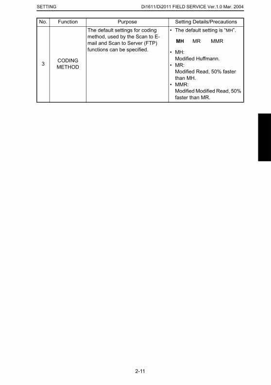
Di1611/Di2011 FIELD SERVICE Ver.1.0 Mar. 2004SETTING
3 CODING METHOD
The default settings for coding method, used by the Scan to E-mail and Scan to Server (FTP) functions can be specified.
• The default setting is “MH”.
MH MR MMR
• MH: Modified Huffmann.
• MR: Modified Read, 50% faster than MH.
• MMR: Modified Modified Read, 50% faster than MR.
No. Function Purpose Setting Details/Precautions
2-11

Di1611/Di2011 FIELD SERVICE Ver.1.0 Mar. 2004 SETTING
2-12

TROUBLESHOOTING
19971
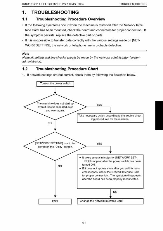
Di1611/Di2011 FIELD SERVICE Ver.1.0 Mar. 2004 TROUBLESHOOTING
1. TROUBLESHOOTING1.1 Troubleshooting Procedure Overview• If the following symptoms occur when the machine is restarted after the Network Inter-
face Card has been mounted, check the board and connectors for proper connection. If the symptom persists, replace the defective part or parts.
• If it is not possible to transfer data correctly with the various settings made on [NET-WORK SETTING], the network or telephone line is probably defective.
NoteNetwork setting and line checks should be made by the network administrator (system administrator).
1.2 Troubleshooting Procedure Chart1. If network settings are not correct, check them by following the flowchart below.
The machine does not start up even if reset is repeated over
and over again.
[NETWORK SETTING] is not dis-played on the “Utility” screen.
Take necessary action according to the trouble shoot-ing procedures for the machine.
• It takes several minutes for [NETWORK SET-TING] to appear after the power switch has been turned ON.
• If it does not appear even after you wait for sev-eral seconds, check the Network Interface Card for proper connection. The symptom disappears after the board has been properly reconnected.
NO
YES
YES
Turn on the power switch
END
NO
Change the Network Interface Card.
NO
4-1
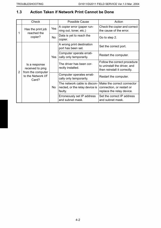
Di1611/Di2011 FIELD SERVICE Ver.1.0 Mar. 2004TROUBLESHOOTING
1.3 Action Taken if Network Print Cannot be Done
Check Possible Cause Action
1Has the print job
reached the copier?
Yes A copier error (paper run-ning out, toner, etc.)
Check the copier and correct the cause of the error.
No Data is yet to reach the copier. Go to step 2.
2
Is a response received to ping
from the computer to the Network I/F
Card?
Yes
A wrong print destination port has been set. Set the correct port.
Computer operate errati-cally only temporarily. Restart the computer.
The driver has been cor-rectly installed.
Follow the correct procedure to uninstall the driver, and then reinstall it correctly.
No
Computer operates errati-cally only temporarily. Restart the computer.
The network cable is discon-nected, or the relay device is faulty.
Make the correct connector connection, or restart or replace the relay device.
Erroneously set IP address and subnet mask.
Set the correct IP address and subnet mask.
4-2