Embed Size (px)
Citation preview
www.kontron.comIf it's embedded, it's Kontron.
» Kontron User's Guide «
Document Revision 1.2
Document ID: SK-MAN-AM4904 1036-1597
Issue Date: April 2011
AM4904

ii AM4904 User Guide
www.kontron.com
Revision History
Customer Service
Visit our site at:www.kontron.com
© 2011 Kontron, an International Corporation. All rights reserved.
The information in this user's guide is provided for reference only. Kontron does not assume any liabilityarising out of the application or use of the information or products described herein. This user's guide maycontain or reference information and products protected by copyrights or patents and does not convey anylicense under the patent rights of Kontron, nor the rights of others.
Kontron is a registered trademark of Kontron. All trademarks, registered trademarks, and trade names usedin this user's guide are the property of their respective owners. All rights reserved. Printed in Canada. Thisuser's guide contains information proprietary to Kontron. Customers may reprint and use this user's guidein other publications. Customers may alter this user's guide and publish it only after they remove the Kon-tron name, cover, and logo.
Kontron reserves the right to make changes without notice in product or component design as warranted byevolution in user needs or progress in engineering or manufacturing technology. Changes that affect theoperation of the unit will be documented in the next revision of this user's guide.
Rev. Index Brief Description of Changes Date of Issue
0.1 Initial Issue 3 July, 2009
0.2 Included PCIe and sRIO variants, minor edits 16 September, 2009
1.0 Major edits in all chapters 14 July, 2010
1.1 Minor edits in all chapters 6 April, 2011
1.2 Minor edits in chapter 3 „Operating the Unit“ 14 April, 2011
Contact Information: Kontron Canada, Inc. 4555 Ambroise-LafortuneBoisbriand, Québec, Canada J7H 0A4Tel: (450) 437-5682
(800) 354-4223 Fax: (450) 437-8053E-mail: [email protected]
Kontron Modular Computer GMBH Sudetenstrasse 7 87600 Kaufbeuren Germany +49 (0) 8341 803 333
+49 (0) 8341 803 339 [email protected]
Table of Contents
Revision History ...................................................................................................... ii
Customer Service..................................................................................................... ii
Proprietary Note ..................................................................................................... x
Trademarks............................................................................................................ x
Environmental Protection Statement ........................................................................... x
Before you Begin..................................................................................................... xi
When Working Inside a Computer ................................................................................ xii
Advisory Conventions ............................................................................................... xiii
Safety Instructions .................................................................................................. xiv
Special Handling and Unpacking Instructions ................................................................ xv
General Instructions on Usage.................................................................................... xvi
Regulatory Compliance Statements ............................................................................. xvii
Two Year Warranty ................................................................................................... xviii
1 Introduction ......................................................................................... 21.1 MicroTCA™ System Overview............................................................................ 2
1.2 Product Overview ......................................................................................... 2
1.3 Optional Accessories ..................................................................................... 2
1.4 Technical Specifications ................................................................................ 3
1.4.1 General.............................................................................................. 3
1.4.2 ATCA LEDs........................................................................................... 3
1.4.3 Operating Voltages ............................................................................... 3
1.4.4 Operation Power .................................................................................. 3
1.4.5 Temperature ....................................................................................... 3
1.4.6 Humidity ........................................................................................... 3
1.4.7 Altitude ............................................................................................. 4
1.4.8 Vibration ........................................................................................... 4
1.4.9 Shock................................................................................................ 4
1.4.10 Safety ............................................................................................... 4
1.4.11 Electromagnetic Compatibility ................................................................ 4
1.4.12 MTBF................................................................................................. 5
1.5 Standards Compliance................................................................................... 5
1.6 Related Publications..................................................................................... 5
iii AM4904 User Guide
www.kontron.com
2 Functional Description ............................................................................ 72.1 Block Diagrams ........................................................................................... 7
2.2 MicroTCA Carrier Management Controller ............................................................ 8
2.2.1 Unit Computer PowerPC 405EX ................................................................ 8
2.2.2 DDR2 Memory...................................................................................... 8
2.2.3 NOR Flash .......................................................................................... 9
2.2.4 NAND Flash......................................................................................... 9
2.2.5 Dual GE PHY........................................................................................ 9
2.2.6 FPGA ................................................................................................. 9
2.2.7 I2C EEPROM ........................................................................................ 10
2.2.8 Real Time Clock (RTC)............................................................................ 10
2.2.9 Serial Interface.................................................................................... 10
2.2.10 FE Management................................................................................... 10
2.2.11 Board Sensors ..................................................................................... 10
2.3 Managed Ethernet Switch............................................................................... 16
2.3.1 Fabric [A] Switch ................................................................................. 16
2.3.2 Switch Management Software ................................................................. 17
2.4 PCI Express / Serial RapidIO Switch................................................................... 21
2.5 Clocking..................................................................................................... 23
2.5.1 PCIe Clock Distribution .......................................................................... 23
2.5.2 Telco Clock Distribution ......................................................................... 23
2.6 Board Interfaces .......................................................................................... 24
2.6.1 Module Management LEDs...................................................................... 26
2.6.2 MCH/AMC Status LEDs ........................................................................... 27
2.6.3 Synchronisation Clock LEDs .................................................................... 28
2.6.4 Power Module and Cooling Unit Status LEDs................................................ 29
2.6.5 Module Handle Positions ....................................................................... 29
2.6.6 Serial Port .......................................................................................... 30
2.6.7 Management Ethernet Interface (10/100/1000Base-T)................................ 31
2.6.8 Uplink Ethernet Ports ............................................................................ 31
2.6.9 sRIO DensiShield™ Interfaces.................................................................. 32
2.7 MCH Interconnection .................................................................................... 34
2.7.1 Fabric Interface ................................................................................... 35
2.7.2 IPMB-L Interface.................................................................................. 35
2.7.3 Inter-MCH IPMB-L Interface .................................................................... 35
2.7.4 IPMB-0 Interface ................................................................................. 35
2.7.5 MCH Update Channel Interface ................................................................ 35
2.7.6 JTAG Interface..................................................................................... 35
2.7.7 Pinout of MCH Card-edge Connectors......................................................... 35
iv AM4904 User Guide
www.kontron.com
3 Operating the Unit ................................................................................. 483.1 Board Access............................................................................................... 48
3.2 MCMC/CM application.................................................................................... 49
3.2.1 CM Configuration Options....................................................................... 49
3.2.2 CM Modules ........................................................................................ 50
3.3 CM Command Line Interface (CLI) .................................................................... 51
3.3.1 Accessing MCMC: clicm .......................................................................... 51
3.3.2 CM Commands ..................................................................................... 51
3.3.3 Counter Commands............................................................................... 52
3.3.4 Ekeying Commands .............................................................................. 52
3.3.5 Fan Commands.................................................................................... 52
3.3.6 Fru Commands .................................................................................... 53
3.3.7 IPMB Commands.................................................................................. 53
3.3.8 Boot option Commands ......................................................................... 53
3.3.9 I2C Commands .................................................................................... 54
3.3.10 LAN Commands.................................................................................... 54
3.3.11 Log Commands .................................................................................... 54
3.3.12 MC Commands ..................................................................................... 55
3.3.13 Memory Commands .............................................................................. 55
3.3.14 Monitor Commands .............................................................................. 55
3.3.15 MP Commands..................................................................................... 56
3.3.16 PCIe Commands ................................................................................... 56
3.3.17 PM Commands..................................................................................... 57
3.3.18 Redundancy Commands......................................................................... 57
3.3.19 SEL Commands .................................................................................... 57
3.3.20 Sensor Commands ................................................................................ 57
3.3.21 SRIO Commands .................................................................................. 58
3.3.22 Clock Commands .................................................................................. 58
3.3.23 Miscellaneous Commands ...................................................................... 59
3.4 System Configuration Tools ............................................................................ 59
3.4.1 Accessing the PLD: pldtool...................................................................... 59
3.4.2 Accessing Switch Management: fpcli......................................................... 59
3.4.3 Accessing MCMC: ipmitool ...................................................................... 60
3.4.4 Configuring services: chkconfig ............................................................... 61
3.4.5 Configuring PCI Express ......................................................................... 62
3.4.6 Configuring sRIO.................................................................................. 64
3.4.7 Clocking Configuration .......................................................................... 65
3.4.8 MCH Redundancy Support ...................................................................... 70
3.4.9 Cooling Unit Management...................................................................... 70
3.5 IPMI ......................................................................................................... 72
3.5.1 Supported IPMI Commands..................................................................... 72
v AM4904 User Guide
www.kontron.com
3.5.2 Board FRU Information ......................................................................... 79
3.6 Bootloader ................................................................................................. 80
3.6.1 Power On Self Test ................................................................................ 80
3.6.2 Bootloader shell and options .................................................................. 81
3.7 Firmware Administration ............................................................................... 82
3.7.1 Updating Firmware............................................................................... 83
4 Hardware Installation ............................................................................ 864.1 Safety Requirements..................................................................................... 86
4.2 Hot Swap Procedures .................................................................................... 87
4.2.1 Hot Swap Insertion............................................................................... 87
4.2.2 Hot Swap Extraction ............................................................................. 88
5 Power Considerations.............................................................................. 915.1 AM4904 Input Voltage Ranges ........................................................................ 91
5.2 Carrier Power Requirements ............................................................................ 91
5.2.1 Payload Power..................................................................................... 91
5.2.2 Management Power .............................................................................. 92
5.2.3 Payload and Management Voltage Ramp ................................................... 92
5.3 Power Consumption ...................................................................................... 92
5.3.1 Payload Power Consumption ................................................................... 92
5.3.2 Management Power Consumption ............................................................ 93
5.4 Payload Start-Up Current of the AM4904............................................................ 93
6 Thermal Considerations........................................................................... 956.1 Thermal Monitoring ...................................................................................... 95
6.2 Thermal Regulation ...................................................................................... 98
6.3 Airflow ...................................................................................................... 99
A Configuration Options............................................................................. A-2
B Getting Help.......................................................................................... B-2B.1 Returning Defective Merchandise .................................................................... B-2
B.2 When Returning a Unit ................................................................................. B-3
C Glossary ............................................................................................... C-2
vi AM4904 User Guide
www.kontron.com
List of Tables
Table 1-1: Related Publications ................................................................................... 5Table 2-1: Sensor List AM4904-Base ........................................................................... 11Table 2-2: Sensor List AM4904-PCIe............................................................................ 12Table 2-3: Sensor List AM4904-sRIO ........................................................................... 13Table 2-4: AM4904 Temperature Sensor Thresholds [°C] ................................................. 14Table 2-5: AM4904 Voltage Sensor Thresholds............................................................... 14Table 2-6: Sensor Type Codes and Event offsets ............................................................. 15Table 2-7: FASTPATH AM4904 Switch Port Mapping......................................................... 16Table 2-8: AM4904-PCIe Switch Port Mapping ............................................................... 22Table 2-9: AM4904-sRIO Switch Port Mapping ............................................................... 23Table 2-10: Module Management LEDs Function.............................................................. 26Table 2-11: AMC and other MCH LEDs ............................................................................ 27Table 2-12: Synchronisation Cock LEDs ......................................................................... 27Table 2-13: PLL Status .............................................................................................. 28Table 2-14: MCH LED Status........................................................................................ 28Table 2-15: Module Handle Positions............................................................................ 29Table 2-16: Serial Port Pinout ..................................................................................... 29Table 2-17: Management RJ45 Connector Pin Assignment ................................................. 30Table 2-18: Management LEDs Signification................................................................... 30Table 2-19: GbE Connector ......................................................................................... 31Table 2-20: Ethernet LED Status .................................................................................. 31Table 2-21: sRIO Connections ..................................................................................... 31Table 2-22: DensiShield™ Uplink Connector Pinout .......................................................... 32Table 2-23: DensiShield™ to InfiniBand Adapter Wiring .................................................... 33Table 2-24: MCH Card-edge Tongue 1 Connectors Pinout.................................................... 35Table 2-25: MCH Card-edge Tongue 2 (Clocking) Connectors Pinout ..................................... 37Table 2-26: MCH Card-edge Tongue 3 (PCIe fabric) Connectors Pinout .................................. 39Table 2-27: MCH Card-edge Tongue 3 (sRIO fabric) Connectors Pinout .................................. 41Table 2-28: MCH Card-edge Tongue 4 Connectors Pinout.................................................... 43Table 3-1: Management Interfaces............................................................................. 47Table 3-2: Configuration File Precedence ..................................................................... 48Table 3-3: Available Modules .................................................................................... 49Table 3-4: CLI CM Commands .................................................................................... 50Table 3-5: CLI Counter Commands .............................................................................. 51Table 3-6: CLI Ekeying Commands .............................................................................. 51Table 3-7: CLI Fan Commands ................................................................................... 51Table 3-8: CLI Fru Commands .................................................................................... 52Table 3-9: CLI IPMB Commands ................................................................................. 52Table 3-10: CLI boot option Commands ......................................................................... 52
vii AM4904 User Guide
www.kontron.com
Table 3-11: CLI I2C Commands.................................................................................... 53Table 3-12: CLI LAN Commands ................................................................................... 53Table 3-13: CLI Log Commands ................................................................................... 53Table 3-14: CLI MC Commands .................................................................................... 54Table 3-15: CLI Memory Commands .............................................................................. 54Table 3-16: CLI Monitor Commands .............................................................................. 54Table 3-17: CLI MP Commands .................................................................................... 55Table 3-18: CLI PCIe Commands .................................................................................. 55Table 3-19: CLI PM Commands .................................................................................... 56Table 3-20: CLI RM Commands .................................................................................... 56Table 3-21: CLI SEL Commands.................................................................................... 56Table 3-22: CLI Sensor Commands ............................................................................... 56Table 3-23: CLI sRIO Commands .................................................................................. 57Table 3-24: CLI Clock Commands ................................................................................. 57Table 3-25: CLI Miscellaneous Commands ...................................................................... 58Table 3-26: PCI Express Settings .................................................................................. 62Table 3-27: SRIO Settings .......................................................................................... 63Table 3-28: PLL Settings ............................................................................................ 65Table 3-29: Command output ..................................................................................... 68Table 3-30: FAN control states .................................................................................... 70Table 3-31: IPMI Device Commands.............................................................................. 71Table 3-32: PICMG Commands..................................................................................... 75Table 3-33: AMC.0 Commands..................................................................................... 76Table 3-34: MicroTCA.0 Commands............................................................................... 76Table 3-35: Kontron specific OEM Commands.................................................................. 76Table 3-36: POST Routines and Error Codes .................................................................... 79Table 3-37: Bootloader Environment Variables................................................................ 80Table 3-38: FLASH Partition Scheme (64MB).................................................................. 81Table 5-1: DC Operational Input Voltage Ranges ............................................................ 90Table 5-2: Payload Power Consumption ...................................................................... 91Table 6-1: MCMC Temperature Sensors Thresholds .......................................................... 96Table 6-2: Airflow values.......................................................................................... 100Table A-1: CM configuration file settings...................................................................... A-2
viii AM4904 User Guide
www.kontron.com
ix AM4904 User Guide
www.kontron.com
List of Figures
Figure 2-1: AM4904 Functional Block Diagram ............................................................... 7
Figure 2-2: PCIe fabric.............................................................................................21
Figure 2-3: sRIO fabric ............................................................................................22
Figure 2-4: AM4904-Base Front Panel LEDs and Interfaces ...............................................25
Figure 2-5: AM4904-PCIe Front Panel LEDs and Interfaces................................................25
Figure 2-6: AM4904-sRIO Front Panel LEDs and Interfaces ...............................................25
Figure 2-7: Module Handle Positions...........................................................................28
Figure 2-8: DensiShield™ Uplink Cable Connector Face (Front Connector is mirrored) .............32
Figure 6-1: Temperature Sensor Locations AM4904 (Base variant, top view) ........................94
Figure 6-2: Temperature Sensor Locations AM4904 (Base variant, bottom view) ...................95
Figure 6-3: Temperature Sensor Locations AM4904 (PCIe variant, bottom view)....................95
Figure 6-4: Temperature Sensor Locations AM4904 (sRIO variant, top view).........................96
Figure 6-5: Maximum ambient and inlet temperature versus airflow ...................................97
Figure 6-6: Impedance Curve AM4904-Base ..................................................................98
Figure 6-7: Impedance Curve AM4904-PCIe ..................................................................98
Figure 6-8: Impedance Curve AM4904-sRIO ..................................................................99
Figure 6-9: Airflow Distribution AM4904-Base...............................................................99
Figure 6-10: Airflow Distribution AM4904-PCIe ............................................................. 100
Figure 6-11: Airflow Distribution AM4904-sRIO ............................................................ 100

Preface
Proprietary Note
This document contains information proprietary to Kontron AG. It may not be copied or transmitted by anymeans, disclosed to others, or stored in any retrieval system or media without the prior written consent ofKontron AG or one of its authorized agents.
The information contained in this document is, to the best of our knowledge, entirely correct. However, Kon-tron AG cannot accept liability for any inaccuracies or the consequences thereof, or for any liability arisingfrom the use or application of any circuit, product, or example shown in this document.
Kontron AG reserves the right to change, modify, or improve this document or the product described herein,as seen fit by Kontron AG without further notice.
Trademarks
Kontron AG and the Kontron logo are trade marks owned by Kontron AG, Germany. In addition, this docu-ment may include names, company logos and trademarks, which are registered trademarks and, therefore,proprietary to their respective owners.
Environmental Protection Statement
This product has been manufactured to satisfy environmental protection requirements where possible. Manyof the components used (structural parts, printed circuit boards, connectors, batteries, etc.) are capable ofbeing recycled.
Final disposition of this product after its service life must be accomplished in accordance with applicablecountry, state, or local laws or regulations.
x AM4904 User Guide
www.kontron.com

Preface
Before you Begin
Before handling the board, read the instructions and safety guidelines on the following pages to preventdamage to the product and to ensure your own personal safety. Refer to the "Advisory Conventions" sectionfor advisory conventions used in this user's guide, including the distinction between Warnings, Cautions andNotes.
• Always use caution when handling/operating the computer. Only qualified, experienced, authorizedelectronics service personnel should access the interior of the computer. The power supplies producehigh voltages and energy hazards, which can cause bodily harm.
• Use extreme caution when installing or removing components. Refer to the installation instructions inthis user's guide for precautions and procedures. If you have any questions, please contact KontronTechnical Support
WARNING
High voltages are present inside the chassis when the unit’s powercord is plugged into an electrical outlet. Turn off system power,turn off the power supply, and then disconnect the power cord fromits source before removing the chassis cover. Turning off the systempower switch does not remove power to components.
xi AM4904 User Guide
www.kontron.com
Preface
When Working Inside a Computer
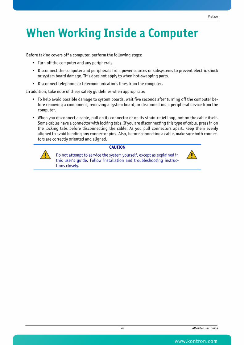
Before taking covers off a computer, perform the following steps:
• Turn off the computer and any peripherals.
• Disconnect the computer and peripherals from power sources or subsystems to prevent electric shockor system board damage. This does not apply to when hot-swapping parts.
• Disconnect telephone or telecommunications lines from the computer.
In addition, take note of these safety guidelines when appropriate:
• To help avoid possible damage to system boards, wait five seconds after turning off the computer be-fore removing a component, removing a system board, or disconnecting a peripheral device from thecomputer.
• When you disconnect a cable, pull on its connector or on its strain-relief loop, not on the cable itself.Some cables have a connector with locking tabs. If you are disconnecting this type of cable, press in onthe locking tabs before disconnecting the cable. As you pull connectors apart, keep them evenlyaligned to avoid bending any connector pins. Also, before connecting a cable, make sure both connec-tors are correctly oriented and aligned.
CAUTION
Do not attempt to service the system yourself, except as explained inthis user’s guide. Follow installation and troubleshooting instruc-tions closely.
xii AM4904 User Guide
www.kontron.com

Preface
Advisory Conventions
CAUTION
This symbol and title indicate potential damage to hardware and tellsyou how to avoid the problem.
CAUTION
Electric Shock
This symbol and title warn of hazards due to electrical shocks (> 60V)when touching products or parts of them. Failure to observe the pre-cautions indicated and/or prescribed by the law may endanger yourlife/health and/or result in damage to your material.
WARNING
This symbol and title emphasize points which, if not fully understoodand taken into consideration by the reader, may endanger yourhealth and/or result in damage to your material.
ESD Sensitive Device
This symbol and title inform that electronic boards and their components aresensitive to static electricity. Therefore, care must be taken during all handlingoperations and inspections of this product, in order to ensure product integrityat all times.
Please read also the section “Special Handling and Unpacking Instructions”.
Note...
This symbol and title emphasize aspects the reader should read through carefullyfor his or her own advantage.
CE Conformity
This symbol indicates that the product described in this manual is in compliancewith all applied CE standards. Please refer also to the section “Regulatory Com-pliance Statements” in this manual.
xiii AM4904 User Guide
www.kontron.com

Preface
Safety Instructions
Your new Kontron product was developed and tested carefully to provide all features necessary to ensure itscompliance with electrical safety requirements. It was also designed for a long fault-free life. However, thelife expectancy of your product can be drastically reduced by improper treatment during unpacking andinstallation. Therefore, in the interest of your own safety and of the correct operation of your new Kontronproduct, you are requested to conform with the following guidelines.
WARNING
All operations on this device must be carried out by sufficientlyskilled personnel only.
WARNING
Do not connect a switch port to a telephone line.
WARNING
For installation in a Hot-Plug system, observe the safety instruc-tions specific to the system. Read the relevant documentation.
CAUTION
Electric Shock
High voltages are present inside the chassis when the unit’s powercord is plugged into an electrical outlet. Turn off system power, turnoff the power supply, and then disconnect the power cord from itssource before removing the chassis cover. Turning off the systempower switch does not remove power to components.
Caution, Laser Light!
Laser light from fiber-optic transmission cables and components can damageyour eyes. The laser components plugged into the switch are Class 1 laser compo-nents. Class 1 laser is considered incapable of producing damaging radiation lev-els during normal operation or maintenance.
To avoid damaging your eyes and to continue safe operation in case of abnormalcircumstances:
• Never look directly into the outlets of fiber-optic transmission componentsor fiber-optic cables with unprotected eyes.
• Never allow fiber-optic transmission path to operate until all the connec-tions have been made.
• Always fit protective plugs to any unused ports of the switch.
xiv AM4904 User Guide
www.kontron.com

Preface
Special Handling and Unpacking Instructions
Unpacking
Follow these recommendations while unpacking:
• Remove all items from the box. If any items listed on the purchase order are missing, notify Kontroncustomer service immediately.
• Inspect the product for damage. If there is damage, notify Kontron customer service immediately.
• Keep all the original packaging material for future storage or warranty shipments. If it is necessary tostore or ship the board please re-pack it as nearly as possible in the manner in which it was delivered.
Do not handle this product out of its protective enclosure while it is not used for operational purposes unlessit is otherwise protected.
Whenever possible, unpack or pack this product only at EOS/ESD safe work stations. Where a safe work sta-tion is not guaranteed, it is important for the user to be electrically discharged before touching the productwith his/her hands or tools. This is most easily done by touching a metal part of your system housing.
It is particularly important to observe standard anti-static precautions when changing mezzanines, ROMdevices, jumper settings etc. If the product contains batteries for RTC or memory back-up, ensure that theboard is not placed on conductive surfaces, including anti-static plastics or sponges. They can cause shortcircuits and damage the batteries or conductive circuits on the board.
Powering up the System
Before any installation or setup, ensure that the board is unplugged from power sources or subsystems.
If you encounter a problem, verify the following items:
• Make sure that all connectors are properly connected.
• Verify your boot devices.
• If the system does not start properly, try booting without any other I/O peripherals attached, includingAMC adapters.
ESD Sensitive Device
This symbol and title inform that electronic boards and their componentsare sensitive to static electricity. Therefore, care must be taken duringall handling operations and inspections of this product, in order toensure product integrity at all times.
xv AM4904 User Guide
www.kontron.com

Preface
Make sure your system provides the minimum DC voltages required at the board's slot, especially if DC poweris carried by cables.
If you are still not able to get your board running, contact our Technical Support for assistance.
Storing the Boards
Electronic boards are sensitive devices. Do not handle or store device near strong electrostatic, electromag-netic, magnetic or radioactive fields.
General Instructions on Usage
In order to maintain Kontron’s product warranty, this product must not be altered or modified in any way.Changes or modifications to the device, which are not explicitly approved by Kontron AG and described inthis manual or received from Kontron’s Technical Support as a special handling instruction, will void yourwarranty.
This device should only be installed in or connected to systems that fulfill all necessary technical and spe-cific environmental requirements. This applies also to the operational temperature range of the specificboard version, which must not be exceeded. If batteries are present their temperature restrictions must betaken into account.
xvi AM4904 User Guide
www.kontron.com

Preface
Regulatory Compliance Statements
FCC Compliance Statement for Class B Devices
This equipment has been tested and found to comply with the limits for a Class B digital device, pursuant toPart 15 of the FCC Rules. These limits are designed to provide reasonable protection against harmful interfer-ence in a residential installation. This equipment generated, uses and can radiate radio frequency energyand, if not installed and used in accordance with the instructions may cause harmful interference to radiocommunications. However, there is no guarantee that interference will not occur in a particular installation.If this equipment does cause harmful interference to radio or television reception, which can be determinedby turning the equipment off and on, the user is encouraged to try to correct the interference by one or moreof the following measures:
• Reorient or relocate the receiving antenna.
• Increase the separation between the equipment and receiver.
• Connect the equipment into an outlet on a circuit different from that to which the receiver is connect-ed.
• Consult the dealer or an experience radio/TV technician for help.
Safety Certification
All Kontron equipment meets or exceeds safety requirements based on the IEC/EN/UL/CSA 60950-1 family ofstandards entitled, "Safety of information technology equipment." All components are chosen to reducefire hazards and provide insulation and protection where necessary. Testing and reports when required areperformed under the international IECEE CB Scheme. Please consult the "Kontron Safety Conformity PolicyGuide" for more information.
CE Certification
The product described in this user's guide was tested in a representative system and is found to be compliantwith the CE marking requirements. For computer systems to remain CE compliant, only CE-compliant partsmay be used. Maintaining CE compliance also requires proper cable and cabling techniques. Although Kon-tron offers accessories, the customer must ensure that these products are installed with proper shielding tomaintain CE compliance. Kontron does not offer engineering services for designing cabling systems. In addi-tion, Kontron will not retest or recertify systems or components that have been reconfigured by customers.
WARNING
This is a Class B product. If not installed in a properly shielded enclo-sure and used in accordance with this User's Guide, this product maycause radio interference in which case users may need to take addi-tional measures at their own expense.
xvii AM4904 User Guide
www.kontron.com

Preface
Two Year Warranty
Kontron AG grants the original purchaser of Kontron’s products a TWO YEAR LIMITED HARDWARE WARRANTY asdescribed in the following. However, no other warranties that may be granted or implied by anyone on behalfof Kontron are valid unless the consumer has the express written consent of Kontron AG.
Kontron AG warrants their own products, excluding software, to be free from manufacturing and materialdefects for a period of 24 consecutive months from the date of purchase. This warranty is not transferablenor extendible to cover any other users or long-term storage of the product. It does not cover productswhich have been modified, altered or repaired by any other party than Kontron Modular Computers GmbH ortheir authorized agents. Furthermore, any product which has been, or is suspected of being damaged as aresult of negligence, improper use, incorrect handling, servicing or maintenance, or which has been dam-aged as a result of excessive current/voltage or temperature, or which has had its serial number(s), anyother markings or parts thereof altered, defaced or removed will also be excluded from this warranty.
If the customer’s eligibility for warranty has not been voided, in the event of any claim, he may return theproduct at the earliest possible convenience to the original place of purchase, together with a copy of theoriginal document of purchase, a full description of the application the product is used on and a descriptionof the defect. Pack the product in such a way as to ensure safe transportation (see our safety instructions).
Kontron provides for repair or replacement of any part, assembly or sub-assembly at their own discretion, orto refund the original cost of purchase, if appropriate. In the event of repair, refunding or replacement ofany part, the ownership of the removed or replaced parts reverts to Kontron Modular Computers GmbH, andthe remaining part of the original guarantee, or any new guarantee to cover the repaired or replaced items,will be transferred to cover the new or repaired items. Any extensions to the original guarantee are consid-ered gestures of goodwill, and will be defined in the “Repair Report” issued by Kontron with the repaired orreplaced item.
Kontron Modular Computers GmbH will not accept liability for any further claims resulting directly or indi-rectly from any warranty claim, other than the above specified repair, replacement or refunding. In particu-lar, all claims for damage to any system or process in which the product was employed, or any loss incurred asa result of the product not functioning at any given time, are excluded. The extent of Kontron Modular Com-puters GmbH liability to the customer shall not exceed the original purchase price of the item for which theclaim exists.
Kontron Modular Computers GmbH issues no warranty or representation, either explicit or implicit, withrespect to its products’ reliability, fitness, quality, marketability or ability to fulfil any particular applicationor purpose. As a result, the products are sold “as is,” and the responsibility to ensure their suitability for anygiven task remains that of the purchaser. In no event will Kontron be liable for direct, indirect or consequen-tial damages resulting from the use of our hardware or software products, or documentation, even if Kontronwere advised of the possibility of such claims prior to the purchase of the product or during any period sincethe date of its purchase.
Please remember that no Kontron Modular Computers GmbH employee, dealer or agent is authorized to makeany modification or addition to the above specified terms, either verbally or in any other form, written orelectronically transmitted, without the company’s consent.
xviii AM4904 User Guide
www.kontron.com

1KTC5520/EATX
Chapter 1
Introduction
www.kontron.com
Introduction
1 Introduction
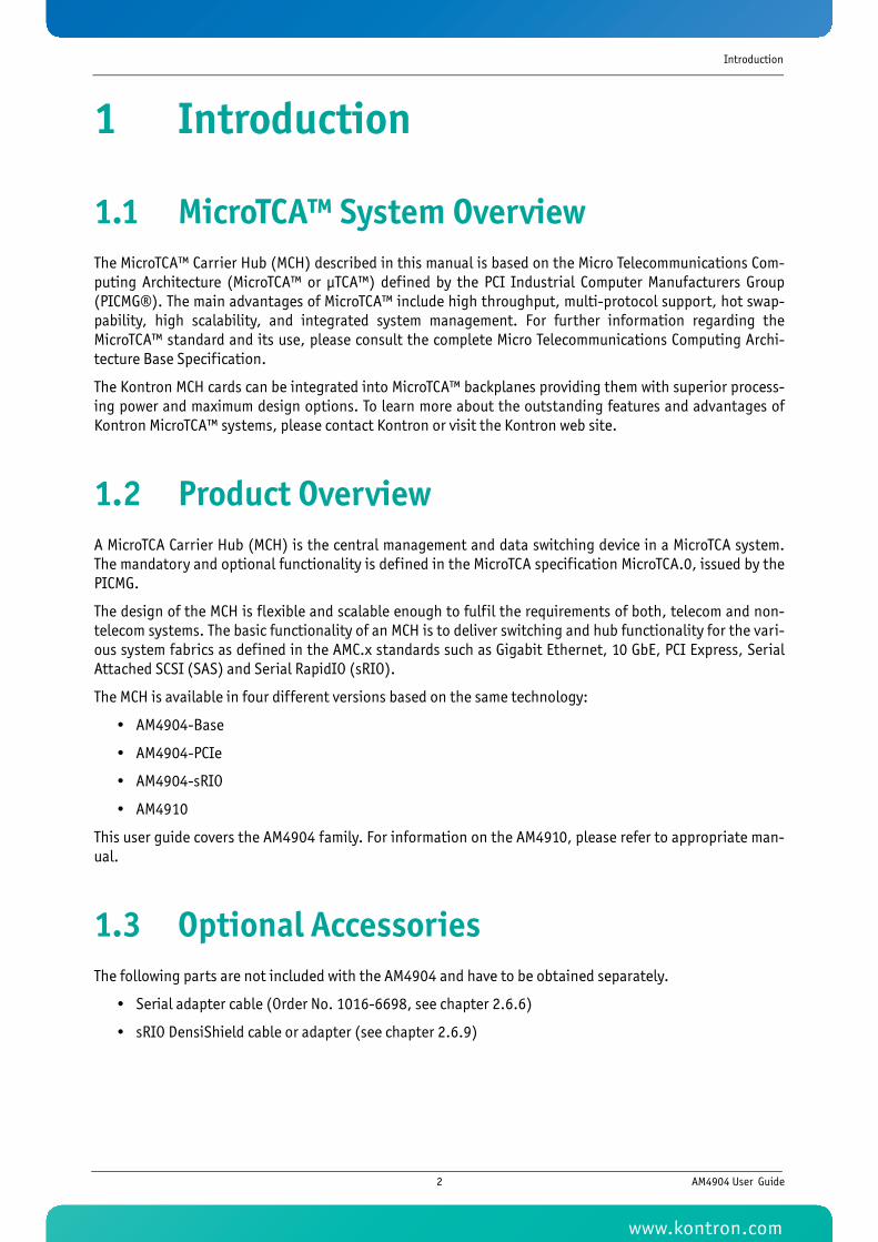
1.1 MicroTCA™ System OverviewThe MicroTCA™ Carrier Hub (MCH) described in this manual is based on the Micro Telecommunications Com-puting Architecture (MicroTCA™ or μTCA™) defined by the PCI Industrial Computer Manufacturers Group(PICMG®). The main advantages of MicroTCA™ include high throughput, multi-protocol support, hot swap-pability, high scalability, and integrated system management. For further information regarding theMicroTCA™ standard and its use, please consult the complete Micro Telecommunications Computing Archi-tecture Base Specification.
The Kontron MCH cards can be integrated into MicroTCA™ backplanes providing them with superior process-ing power and maximum design options. To learn more about the outstanding features and advantages ofKontron MicroTCA™ systems, please contact Kontron or visit the Kontron web site.
1.2 Product OverviewA MicroTCA Carrier Hub (MCH) is the central management and data switching device in a MicroTCA system.The mandatory and optional functionality is defined in the MicroTCA specification MicroTCA.0, issued by thePICMG.
The design of the MCH is flexible and scalable enough to fulfil the requirements of both, telecom and non-telecom systems. The basic functionality of an MCH is to deliver switching and hub functionality for the vari-ous system fabrics as defined in the AMC.x standards such as Gigabit Ethernet, 10 GbE, PCI Express, SerialAttached SCSI (SAS) and Serial RapidIO (sRIO).
The MCH is available in four different versions based on the same technology:
• AM4904-Base
• AM4904-PCIe
• AM4904-sRIO
• AM4910
This user guide covers the AM4904 family. For information on the AM4910, please refer to appropriate man-ual.
1.3 Optional AccessoriesThe following parts are not included with the AM4904 and have to be obtained separately.
• Serial adapter cable (Order No. 1016-6698, see chapter 2.6.6)
• sRIO DensiShield cable or adapter (see chapter 2.6.9)
2 AM4904 User Guide
www.kontron.com
Introduction
1.4 Technical Specifications
1.4.1 General• Mechanical: Single, Full-size AMC form factor
• Dimensions: 180.6 mm x 73.5 mm
• Board Weight:
• AM4904-Base: 350 grams max.
• AM4904-PCIe: 400 grams max.
• AM4904-sRIO: 400 grams max.
1.4.2 ATCA LEDs• LED0 (blue): Ready for Hot Swap
• LED1 (red/green/yellow): Out of Service LED
• LED2 (green/amber/red): Healthy LED
1.4.3 Operating Voltages• Management: 3.3V+/-0.33V
• Payload: 10VDC to 14VDC
1.4.4 Operation Power• Management: 500mW max.
• Payload:
• AM4904-Base: 26.0W max.
• AM4904-PCIe: 40.0W max.
• AM4904-sRIO: 35.0W max.
1.4.5 TemperatureThis board is designed for operation from 0 °C to 55°C inlet air temperature.
• Normal Operating: +5 °C to +40 °C
• Short-Term Operating: -5 °C to +55 °C
1.4.6 HumidityThe board is designed to meet IEC 60068-2-78
• Operating: 5%-93% (non-condensing) at 40°C
• Non-Operating: 5%-95% (non-condensing) at 40°C
3 AM4904 User Guide
www.kontron.com

Introduction
1.4.7 AltitudeThe board is designed to meet the following requirements according Belcore GR-63, Section 4.1.3:
• Operating: 4000 m (13123 ft), may require additional cooling above 1800m(5905ft)
• Non-Operating: 15000 m (49212 ft)
1.4.8 VibrationThe product is designed to meet the following requirements:
• Operating
• 5Hz to 200Hz 0.2G, 5mm/s
• 5HZ to 100Hz: 0.1G @ 0.1 Octave/minute
• 5Hz to 100Hz: 1G @ 0.1 Octave/minute
• 0.02 m²/s³ ASD, 5-10Hz + 12dB/oct, 10-50Hz 0dB/oct, 50-100Hz - 12dB/oct (random)
• Non-Operating
• 5Hz to 200Hz 2G, 5mm/s
• 0.02 m²/s³ ASD, 5-10Hz + 12dB/oct, 10-50Hz 0dB/oct, 50-100Hz - 12dB/oct (random)
• 5Hz to 20Hz: 0.01g²/Hz (random)
• 20Hz to 200Hz: -3dB/octave (random)
1.4.9 ShockThe product is designed to meet the following requirements:
• Operating: 3G/11 ms
• Non-Operating: 18G, 6ms
1.4.10 SafetyCB report to IEC 60950-1, complies with EN/CSA/UL 60950-1.
1.4.11 Electromagnetic CompatibilityThe product is designed to meet or exceed the following specifications/requirements (assuming an adequatecarrier/chassis):
• FCC 47 CFR Part 15, (USA)
• EMC Directive 89/336/EEC (Europe)
• EN55022 (Europe)
• EN55024 (Europe)
• CISPR22
• CISPR24
• VCCI (Voluntary Japan Electromagnetic Compatibility requirement)
4 AM4904 User Guide
www.kontron.com
Introduction
• EN 300 386, Electro-Magnetic Compatibility (EMC) Requirements for Public Telecommunication Net-work Equipment; Electromagnetic Compatibility (EMC) Requirements
• Telcordia GR-1089
1.4.12 MTBF• MTBF is min.: AM4904-Base:170,000h@40°C
• AM4904-sRIO: 148,000h@40°C
• AM4904-PCIe: 160,000h@40°C
Calculations are based on Bellcore/Telcordia SR-332, Issue 1.
1.5 Standards ComplianceThis product is compatible to the following standards:
• AMC.0 R2.0 Advanced Mezzanine Card Base Specification
• AMC.1 R1.0 PCI Express (only AM4904-PCIe)
• AMC.2 R1.0 AMC Gigabit Ethernet
• AMC.2 Type 4 E2• AMC.2 Type 5 E2
• AMC.4 R0.4 SerialRapidIO (only AM4904-sRIO)
• mTCA.0 R1.0
• IPMI v1.5
• IEEE 802.3
The AM4904 is RoHS compliant.
1.6 Related PublicationsThe following publications contain information relating to this product.
PRODUCT PUBLICATION
Table 1-1: Related Publications
PRODUCT PUBLICATION
MicroTCA™ PICMG® MTCA.0 Micro Telecommunications Computing Architecture R1.0, July 6,2006
AMC PICMG® AMC.0, Advanced Mezzanine Card Specif ication R1.0
IPMI IPMI - Intelligent Platform Management Interface Specif ication, v1.5
All Kontron products Product Safety and Implementation Guide, ID 1021-9142
5 AM4904 User Guide
www.kontron.com
6KTC5520/EATX
Chapter 2
Functional Description
www.kontron.com
Functional Description
2 Functional DescriptionThis chapter describes the board specific items of the AM4904 MicroTCA Carrier Hub.
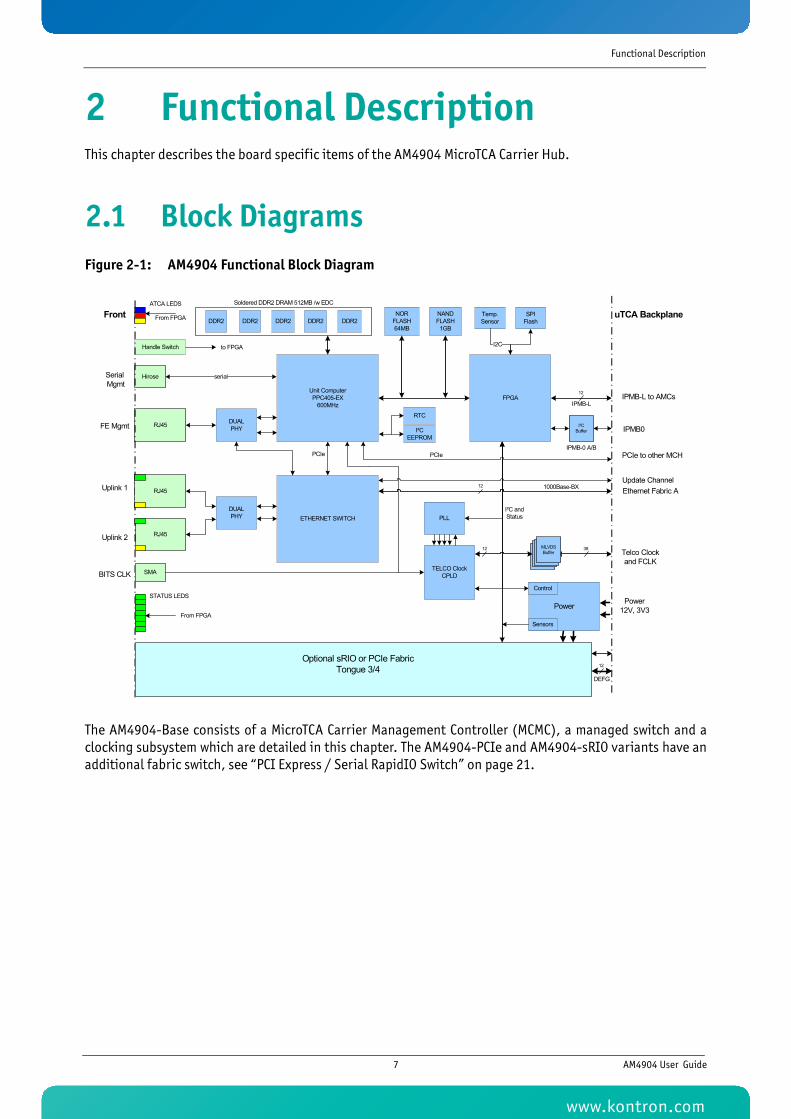
2.1 Block DiagramsFigure 2-1: AM4904 Functional Block Diagram
The AM4904-Base consists of a MicroTCA Carrier Management Controller (MCMC), a managed switch and aclocking subsystem which are detailed in this chapter. The AM4904-PCIe and AM4904-sRIO variants have anadditional fabric switch, see “PCI Express / Serial RapidIO Switch” on page 21.
PCIe
Unit ComputerPPC405-EX
600MHz
Temp. Sensor
Handle Switch I2C
RJ45
Hirose
RJ45
SPI Flash
I²CEEPROM
Power
TELCO Clock CPLD
NAND FLASH
1GBDDR2 DDR2 DDR2 DDR2 DDR2
Soldered DDR2 DRAM 512MB /w EDC
NOR FLASH64MB
FPGA
DUALPHY
ETHERNET SWITCHDUALPHY
RJ45
PLL
SMA
1000Base-BX
BufferMLVDSBufferBufferMLVDSBuffer
Optional sRIO or PCIe FabricTongue 3/4
serial
I²CBuffer
IPMB-0 A/B
IPMB-L
12
12 38
12
I²C and Status
ATCA LEDS
STATUS LEDS
From FPGA
From FPGA
to FPGA
uTCA Backplane
IPMB-L to AMCs
IPMB0
Ethernet Fabric A
Telco Clock and FCLK
Power 12V, 3V3
Sensors
RTC
Uplink 1
FE Mgmt
Front
Uplink 2
Serial Mgmt
BITS CLK
Control
PCIe PCIe to other MCH
DEFG
12
Update Channel
7 AM4904 User Guide
www.kontron.com
Functional Description
2.2 MicroTCA Carrier Management ControllerThe AM4904 supports a processor unit which can operate as only MCMC or as MCMC/CM Software. These twomodes are described in this section.
The MCMC operates with the following building blocks which are detailed below:
• Unit computer PowerPC 405EX
• DDR2 Memory
• NOR Flash
• NAND Flash
• Dual GE PHY
• FPGA
• I2C EEPROM
• Real Time Clock (RTC)
• Serial Management
• FE Management
2.2.1 Unit Computer PowerPC 405EXOne of the main components of the MCMC is the PowerPC 405EX. The following list sets out the key features ofthe PPC 405EX:
• PowerPC 405EX runs at 600MHZ core frequency without security feature (option -N)
• UART 1 to Front, RX, TX
• SPI to FPGA (reserved for optional FPGA update procedure)
• DDR2 SDRAM controller operates at 200MHz/400Mbps with ECC
• PCIe Port 0 lane 0 connects to Ethernet Switch
• PCIe Port 1 lane 0 connects to other MCH via XOVER0/2
• Dual Ethernet MAC operates in RGMII mode and connects to Front Management port and On-BoardSwitch
• EBC interface connects to FPGA and NOR/NAND Flash
• 1 PPS reference pulse input (GPIO) and timer reference clock input (TMRCLK) from either RTC or TelcoPLL via FPGA
The PPC 405EX unit computer does not only implement the MCMC functionality but also hosts the GbE switchmanagement and controls the clocking subsystem.
2.2.2 DDR2 MemoryFive DDR2 Memory modules work with the PowerPC 405EX. The key features of this Memory modules are:
• 512MB, 1024MB or 2048MB DDR2 Memory support with ECC (512MB is the standard memory size)
• 400Mbps double data rate with CAS latency of 2, 2.5 and 3
8 AM4904 User Guide
www.kontron.com
Functional Description
2.2.3 NOR FlashThe NOR Flash holds Firmware, Firmware Configuration, SPD data and FRU data. The NOR FLASH could also beused for limited Logging Tracing.
• Up to 128MB NOR Flash
• Two Firmware images
2.2.4 NAND FlashThe NAND FLASH is used for high volume storage (TFTP Server applications) with high frequency read. TheNAND FLASH could also be used for limited Logging Tracing.
• Up to 4GB with dual-chip select
• High Frequency Read, High Volume Storage, NAND with wear-leveling
• 1024MB standard memory size
2.2.5 Dual GE PHY• Dual 10/100/1000Base-T Ethernet Transceiver
• Port 1 operates in RGMII to 10/100/1000Base-T mode and connects to front low profile RJ45 with in-tegrated magnetics
• Port 2 operates in RGMII to Fiber (SerDes) mode and connects to local Switch Fabric
• Dual PHY distributes 125MHz to PPC405EX GMCRefClk
2.2.6 FPGAThe FPGA is also a main component of the MCMC and has many functions. It has the ability to be upgraded inthe field. The key features of the FPGA are listed below:
• Update configuration FLASH via EBC register Interface
• FPGA Dual Image support
• 16Bit/100 MHz EBC interface to PowerPC 405EX
• 12x IPMB-L to AMC inclusive I2C Pull-Up register control
• 1x IPMB-L Cross-Over to MCH inclusive I2C Pull-Up register control
• 2x IPMB0 + Buffer Control inclusive I2C Pull-Up register control, dual slave address support
• 1x FRU Data I2C Backplane
• 3x I2C to Tongue 1, Tongue 2 and Tongue 3
• MCH-MCH interlink via XOVER1
• Request for takeover
• Heartbeat
• Present
• Isolate request
• Switch-over request
9 AM4904 User Guide
www.kontron.com
Functional Description
• RTC input/output
• LED Bus receiver
• LED distribution
• Board Option Register / Strappings (8bit)
• Watchdog
• Reset Distribution
• Slot address/Site-ID decoding
2.2.7 I2C EEPROMThe I2C EEPROM holds PowerPC 405EX configuration data. The size of the I2C EEPROM is minimum 128bit (16Byte EEPROM bootstrap configuration content. It has a write protection by FPGA and is programmable viaJTAG.
2.2.8 Real Time Clock (RTC)The real time clock is used on the MCMC to keep accurate time. The clock has an integrated micro crystaloscillator. The oscillator’s frequency is 32.768 KHz. The back-up capacity of the RTC is up to 2 weeks.
2.2.9 Serial InterfaceThe PowerPC 405EX is connected to the front plate of the board via a multichannel RS232 Line Transceiver.The serial RS232 interface supports the TX# and RX# signals as well as the RTS, DTR, CTS and DSR signals andoperates with up to 115.2kB/s.
2.2.10 FE ManagementThe front panel provides a direct 10/100/1000 Base-T Ethernet connection (RJ45) to the PPC 405EX for out-of-band management and debugging purposes.
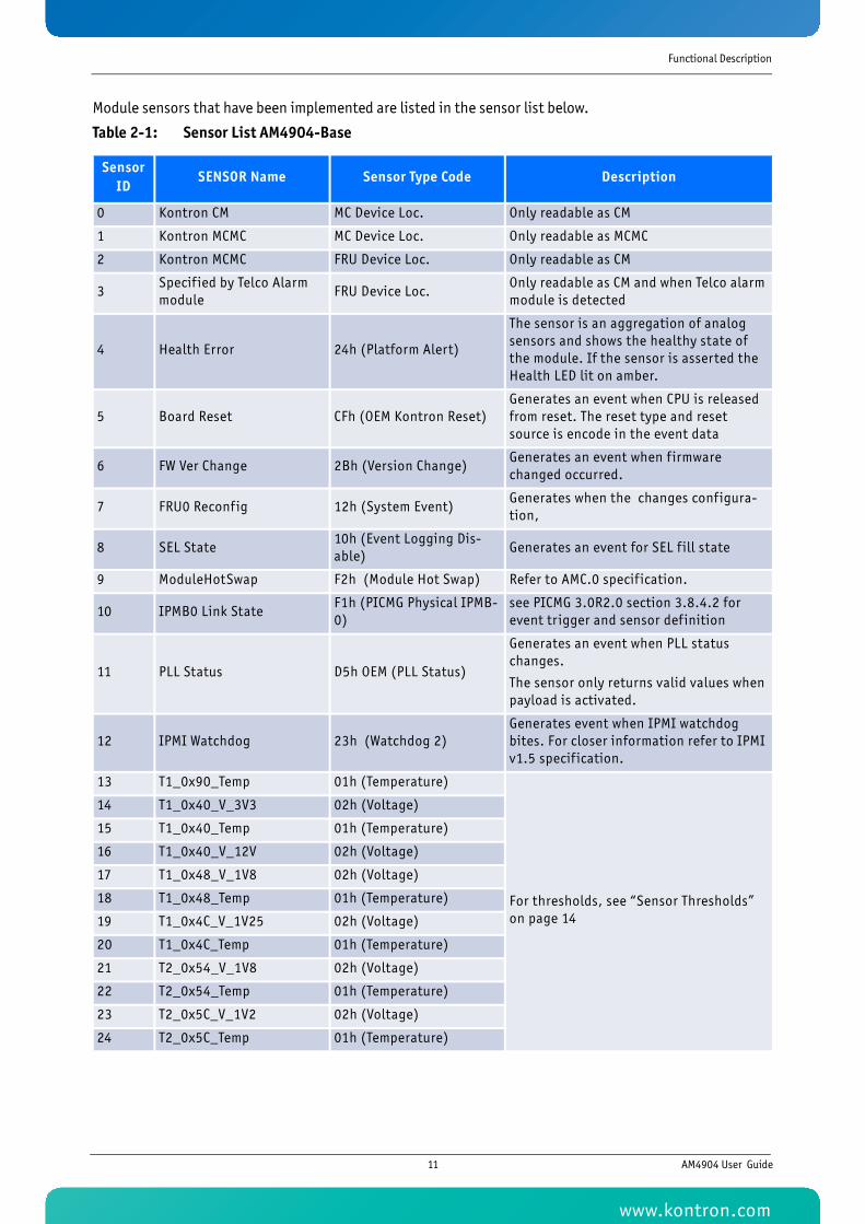
2.2.11 Board SensorsSensors for voltage or temperature monitoring and various others for pass/fail type signal monitoring areprovided.
Every sensor is associated with a Sensor Data Record (SDR). Sensor Data Records contain information aboutthe sensors identification such as sensor type, sensor name, sensor unit. SDRs also contain the configura-tion of a specific sensor such as thresholds, hysteresis, event generation capabilities, etc. that specify thesensor’s behavior. Some fields of the sensor SDR are configurable through IPMI v1.5 command and are set toa built-in initial value.
The sensor ID is the number which identifies the sensor e.g. when using the IPMI command “Get SensorReading”. Please note that ‘ipmitool’ accepts sensor IDs in decimal (e.g. ‘10’) or hexadecimal (e.g. ‘0xa’)notation.
10 AM4904 User Guide
www.kontron.com
Functional Description
Module sensors that have been implemented are listed in the sensor list below.
Table 2-1: Sensor List AM4904-Base
Sensor ID
SENSOR Name Sensor Type Code Description
0 Kontron CM MC Device Loc. Only readable as CM
1 Kontron MCMC MC Device Loc. Only readable as MCMC
2 Kontron MCMC FRU Device Loc. Only readable as CM
3Specif ied by Telco Alarm module
FRU Device Loc.Only readable as CM and when Telco alarm module is detected
4 Health Error 24h (Platform Alert)
The sensor is an aggregation of analog sensors and shows the healthy state of the module. If the sensor is asserted the Health LED lit on amber.
5 Board Reset CFh (OEM Kontron Reset)Generates an event when CPU is released from reset. The reset type and reset source is encode in the event data
6 FW Ver Change 2Bh (Version Change)Generates an event when f irmware changed occurred.
7 FRU0 Reconfig 12h (System Event)Generates when the changes configura-tion,
8 SEL State10h (Event Logging Dis-able)
Generates an event for SEL f ill state
9 ModuleHotSwap F2h (Module Hot Swap) Refer to AMC.0 specif ication.
10 IPMB0 Link StateF1h (PICMG Physical IPMB-0)
see PICMG 3.0R2.0 section 3.8.4.2 for event trigger and sensor definition
11 PLL Status D5h OEM (PLL Status)
Generates an event when PLL status changes.
The sensor only returns valid values when payload is activated.
12 IPMI Watchdog 23h (Watchdog 2)Generates event when IPMI watchdog bites. For closer information refer to IPMI v1.5 specif ication.
13 T1_0x90_Temp 01h (Temperature)
For thresholds, see “Sensor Thresholds” on page 14
14 T1_0x40_V_3V3 02h (Voltage)
15 T1_0x40_Temp 01h (Temperature)
16 T1_0x40_V_12V 02h (Voltage)
17 T1_0x48_V_1V8 02h (Voltage)
18 T1_0x48_Temp 01h (Temperature)
19 T1_0x4C_V_1V25 02h (Voltage)
20 T1_0x4C_Temp 01h (Temperature)
21 T2_0x54_V_1V8 02h (Voltage)
22 T2_0x54_Temp 01h (Temperature)
23 T2_0x5C_V_1V2 02h (Voltage)
24 T2_0x5C_Temp 01h (Temperature)
11 AM4904 User Guide
www.kontron.com

Functional Description
Table 2-2: Sensor List AM4904-PCIe
Sensor ID
SENSOR Name Sensor Type Code Description
0 Kontron CM MC Device Loc. Only readable as CM
1 Kontron MCMC MC Device Loc. Only readable as MCMC
2 Kontron MCMC FRU Device Loc. Only readable as CM
3Specif ied by Telco Alarm module
FRU Device Loc.Only readable as CM and when Telco alarm module is detected
4 Health Error 24h (Platform Alert)
The sensor is an aggregation of analog sensors and shows the healthy state of the module. If the sensor is asserted the Health LED lit on amber.
5 Board Reset CFh (OEM Kontron Reset)Generates an event when CPU is released from reset. The reset type and reset source is encode in the event data
6 FW Ver Change 2Bh (Version Change)Generates an event when f irmware changed occurred.
7 FRU0 Reconfig 12h (System Event)Generates when the changes configura-tion,
8 SEL State10h (Event Logging Dis-able)
Generates an event for SEL f ill state
9 ModuleHotSwap F2h (Module Hot Swap) Refer to AMC.0 specif ication.
10 IPMB0 Link StateF1h (PICMG Physical IPMB-0)
see PICMG 3.0R2.0 section 3.8.4.2 for event trigger and sensor definition
11 PLL Status D5h OEM (PLL Status)
Generates an event when PLL status changes.
The sensor only returns valid values when payload is activated.
12 IPMI Watchdog 23h (Watchdog 2)Generates event when IPMI watchdog bites. For closer information refer to IPMI v1.5 specif ication.
13 T1_0x90_Temp 01h (Temperature)
For thresholds, see “Sensor Thresholds” on page 14
14 T1_0x40_V_3V3 02h (Voltage)
15 T1_0x40_Temp 01h (Temperature)
16 T1_0x40_V_12V 02h (Voltage)
17 T1_0x48_V_1V8 02h (Voltage)
18 T1_0x48_Temp 01h (Temperature)
19 T1_0x4C_V_1V25 02h (Voltage)
20 T1_0x4C_Temp 01h (Temperature)
21 T2_0x54_V_1V8 02h (Voltage)
22 T2_0x54_Temp 01h (Temperature)
23 T2_0x5C_V_1V2 02h (Voltage)
24 T2_0x5C_Temp 01h (Temperature)
25 T3_0x48_V_1V0 02h (Voltage)
26 T3_0x48_Temp 01h (Temperature)
12 AM4904 User Guide
www.kontron.com
Functional Description
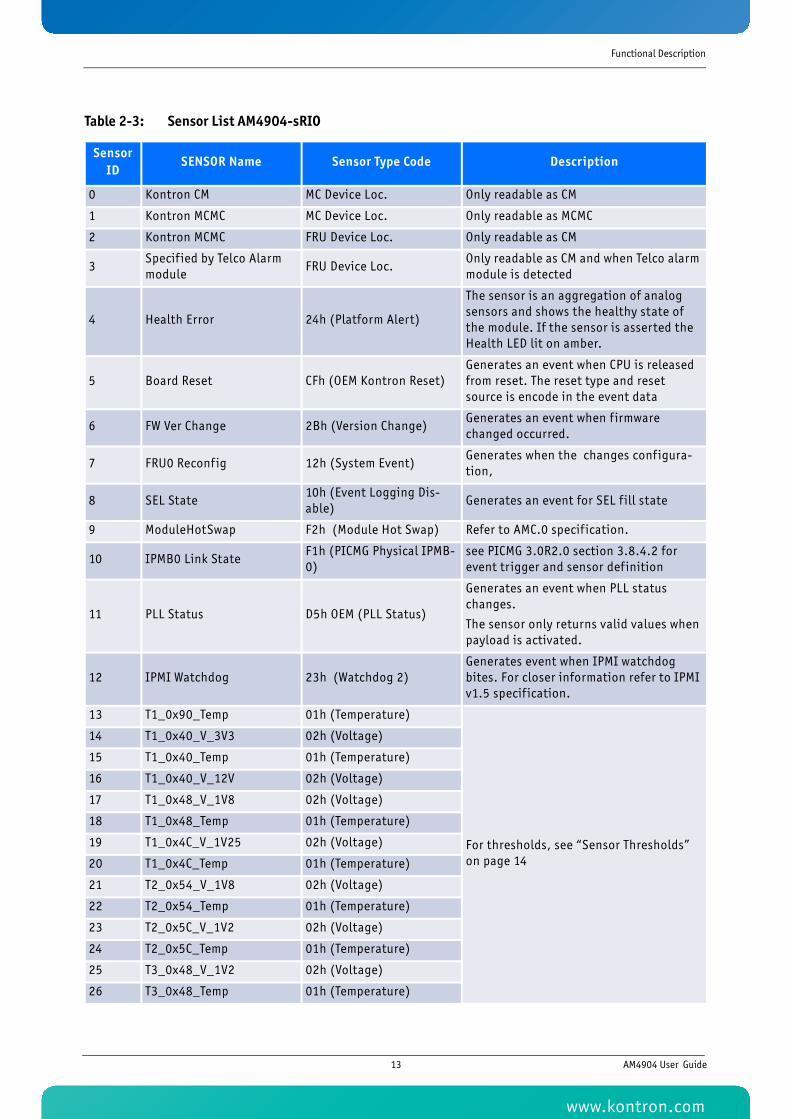
Table 2-3: Sensor List AM4904-sRIO
Sensor ID
SENSOR Name Sensor Type Code Description
0 Kontron CM MC Device Loc. Only readable as CM
1 Kontron MCMC MC Device Loc. Only readable as MCMC
2 Kontron MCMC FRU Device Loc. Only readable as CM
3Specif ied by Telco Alarm module
FRU Device Loc.Only readable as CM and when Telco alarm module is detected
4 Health Error 24h (Platform Alert)
The sensor is an aggregation of analog sensors and shows the healthy state of the module. If the sensor is asserted the Health LED lit on amber.
5 Board Reset CFh (OEM Kontron Reset)Generates an event when CPU is released from reset. The reset type and reset source is encode in the event data
6 FW Ver Change 2Bh (Version Change)Generates an event when f irmware changed occurred.
7 FRU0 Reconfig 12h (System Event)Generates when the changes configura-tion,
8 SEL State10h (Event Logging Dis-able)
Generates an event for SEL f ill state
9 ModuleHotSwap F2h (Module Hot Swap) Refer to AMC.0 specif ication.
10 IPMB0 Link StateF1h (PICMG Physical IPMB-0)
see PICMG 3.0R2.0 section 3.8.4.2 for event trigger and sensor definition
11 PLL Status D5h OEM (PLL Status)
Generates an event when PLL status changes.
The sensor only returns valid values when payload is activated.
12 IPMI Watchdog 23h (Watchdog 2)Generates event when IPMI watchdog bites. For closer information refer to IPMI v1.5 specif ication.
13 T1_0x90_Temp 01h (Temperature)
For thresholds, see “Sensor Thresholds” on page 14
14 T1_0x40_V_3V3 02h (Voltage)
15 T1_0x40_Temp 01h (Temperature)
16 T1_0x40_V_12V 02h (Voltage)
17 T1_0x48_V_1V8 02h (Voltage)
18 T1_0x48_Temp 01h (Temperature)
19 T1_0x4C_V_1V25 02h (Voltage)
20 T1_0x4C_Temp 01h (Temperature)
21 T2_0x54_V_1V8 02h (Voltage)
22 T2_0x54_Temp 01h (Temperature)
23 T2_0x5C_V_1V2 02h (Voltage)
24 T2_0x5C_Temp 01h (Temperature)
25 T3_0x48_V_1V2 02h (Voltage)
26 T3_0x48_Temp 01h (Temperature)
13 AM4904 User Guide
www.kontron.com
Functional Description
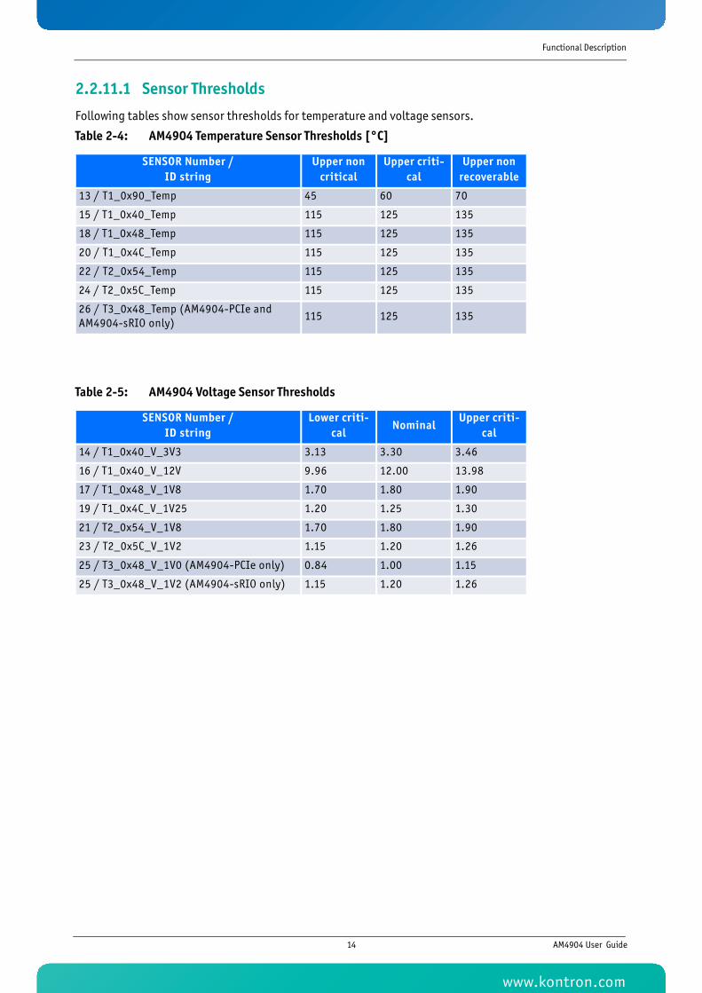
2.2.11.1 Sensor Thresholds
Following tables show sensor thresholds for temperature and voltage sensors.
Table 2-4: AM4904 Temperature Sensor Thresholds [°C]
SENSOR Number / ID string
Upper non critical
Upper criti-cal
Upper non recoverable
13 / T1_0x90_Temp 45 60 70
15 / T1_0x40_Temp 115 125 135
18 / T1_0x48_Temp 115 125 135
20 / T1_0x4C_Temp 115 125 135
22 / T2_0x54_Temp 115 125 135
24 / T2_0x5C_Temp 115 125 135
26 / T3_0x48_Temp (AM4904-PCIe and AM4904-sRIO only)
115 125 135
Table 2-5: AM4904 Voltage Sensor Thresholds
SENSOR Number / ID string
Lower criti-cal
NominalUpper criti-
cal
14 / T1_0x40_V_3V3 3.13 3.30 3.46
16 / T1_0x40_V_12V 9.96 12.00 13.98
17 / T1_0x48_V_1V8 1.70 1.80 1.90
19 / T1_0x4C_V_1V25 1.20 1.25 1.30
21 / T2_0x54_V_1V8 1.70 1.80 1.90
23 / T2_0x5C_V_1V2 1.15 1.20 1.26
25 / T3_0x48_V_1V0 (AM4904-PCIe only) 0.84 1.00 1.15
25 / T3_0x48_V_1V2 (AM4904-sRIO only) 1.15 1.20 1.26
14 AM4904 User Guide
www.kontron.com
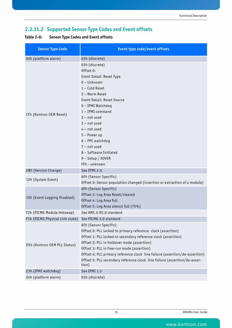
Functional Description
2.2.11.2 Supported Sensor Type Codes and Event offsetsTable 2-6: Sensor Type Codes and Event offsets
Sensor Type Code Event type code/event offsets
24h (platform alarm) 03h (discrete)
CFh (Kontron OEM Reset)
03h (discrete)
Offset 0:
Event Data2: Reset Type
0 – Unknown
1 – Cold Reset
2 – Warm Reset
Event Data3: Reset Source
0 – IPMI Watchdog
1 – IPMI command
2 – not used
3 – not used
4 – not used
5 – Power up
6 – PPC watchdog
7 – not used
8 – Software Initiated
9 – Setup / XOVER
FFh - unknown
2Bh (Version Change) See IPMI 2.0
12h (System Event)6Fh (Sensor Specif ic)
Offset 0: Sensor population changed (insertion or extraction of a module)
10h (Event Logging Disabled)
6Fh (Sensor Specif ic)
Offset 2: Log Area Reset/cleared
Offset 4: Log Area full
Offset 5: Log Area almost full (75%)
F2h (PICMG Module Hotswap) See AMC.0 R2.0 standard
F1h (PICMG Physical Link state) See PICMG 3.0 standard
D5h (Kontron OEM PLL Status)
6Fh (Sensor Specif ic)
Offset 0: PLL locked to primary reference clock (assertion)
Offset 1: PLL locked to secondary reference clock (assertion)
Offset 2: PLL in holdover mode (assertion)
Offset 3: PLL in free-run mode (assertion)
Offset 4: PLL primary reference clock line failure (assertion/de-assertion)
Offset 5: PLL secondary reference clock line failure (assertion/de-asser-tion)
23h (IPMI watchdog) See IPMI 1.5
24h (platform alarm) 03h (discrete)
15 AM4904 User Guide
www.kontron.com
Functional Description
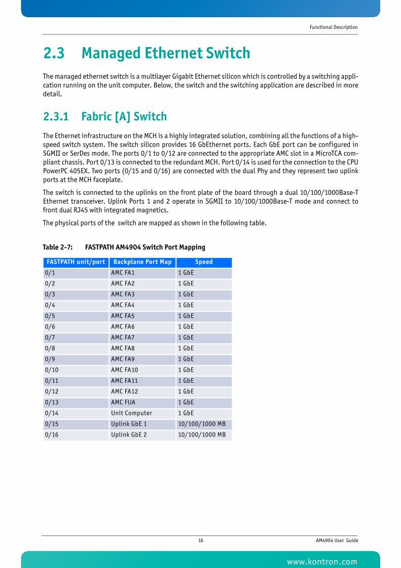
2.3 Managed Ethernet SwitchThe managed ethernet switch is a multilayer Gigabit Ethernet silicon which is controlled by a switching appli-cation running on the unit computer. Below, the switch and the switching application are described in moredetail.
2.3.1 Fabric [A] SwitchThe Ethernet infrastructure on the MCH is a highly integrated solution, combining all the functions of a high-speed switch system. The switch silicon provides 16 GbEthernet ports. Each GbE port can be configured inSGMII or SerDes mode. The ports 0/1 to 0/12 are connected to the appropriate AMC slot in a MicroTCA com-pliant chassis. Port 0/13 is connected to the redundant MCH. Port 0/14 is used for the connection to the CPUPowerPC 405EX. Two ports (0/15 and 0/16) are connected with the dual Phy and they represent two uplinkports at the MCH faceplate.
The switch is connected to the uplinks on the front plate of the board through a dual 10/100/1000Base-TEthernet transceiver. Uplink Ports 1 and 2 operate in SGMII to 10/100/1000Base-T mode and connect tofront dual RJ45 with integrated magnetics.
The physical ports of the switch are mapped as shown in the following table.
Table 2-7: FASTPATH AM4904 Switch Port Mapping
FASTPATH unit/port Backplane Port Map Speed
0/1 AMC FA1 1 GbE
0/2 AMC FA2 1 GbE
0/3 AMC FA3 1 GbE
0/4 AMC FA4 1 GbE
0/5 AMC FA5 1 GbE
0/6 AMC FA6 1 GbE
0/7 AMC FA7 1 GbE
0/8 AMC FA8 1 GbE
0/9 AMC FA9 1 GbE
0/10 AMC FA10 1 GbE
0/11 AMC FA11 1 GbE
0/12 AMC FA12 1 GbE
0/13 AMC FUA 1 GbE
0/14 Unit Computer 1 GbE
0/15 Uplink GbE 1 10/100/1000 MB
0/16 Uplink GbE 2 10/100/1000 MB
16 AM4904 User Guide
www.kontron.com
Functional Description
2.3.2 Switch Management SoftwareThe switch management application is based on Broadcom FASTPATH. It is running as a Linux application onthe main CPU. It coexists with the MCMC/CM application as well as customer software.
For additional information of system configuration refer to “AM4904/AM4910 CLI Reference Manual”.
2.3.2.1 Supported Management RFCs
• RFC 826 - ARP
• RFC 854 - Telnet
• RFC 855 - Telnet Option
• RFC 1155 - SMI v1
• RFC 1157 - SNMP
• RFC 1212 - Concise MIB Definitions
• RFC 1901 - Community based SNMP v2
• RFC 2246 - The TLS Protocol, Version 1.0
• RFC 2271 - SNMP Framework MIB
• RFC 2295 - Transparent Content Negotiation
• RFC 2296 - Remote Variant Selection; RSVA/1.0 State Management "cookies"
• RFC 2346 - AES Ciphersuites for Transport Layer Security
• RFC 2576 - Coexistence between SNMP v1,v2 & v3
• RFC 2578 - SMI v2
• RFC 2579 - Textual Conventions for SMI v2
• RFC 2580 - Conformance statements for SMI v2
• RFC 3410 - Introduction and Applicability Statements for Internet Standard Management Framework
• RFC 3411 - An Architecture for Describing SNMP Management Frameworks
• RFC 3412 - Message Processing and Dispatching (December 2002)
• RFC 3413 - SNMP Applications (December 2002)
• RFC 3414 - User-based Security Model (December 2002)
• RFC 3415 - View-based Access Control Model (December 2002)
• RFC 3416 - Version 2 of SNMP Protocol Operations (December 2002)
• RFC 3417 - Transport Mappings (December 2002)
• RFC 3418 - MIB for the Simple Network Management Protocol.
• RFC 3635 - Definition of Managed Objects for Ethernet-like Interface Types
• SSL 3.0 & TLS 1.0
• SSH 1.5 & 2.0
• Draft-ietf-secsh-transport-16 - SSH Transport Layer Protocol
• Draft-ietf-secsh-userauth-17 - SSH Authentication Protocol
• DRAFT-ietf-secsh-connect-17 - SSH Connection Protocol
17 AM4904 User Guide
www.kontron.com
Functional Description
• Draft-ietf-secsh-architecture-14 - SSH Protocol Architecture
• Draft-ietf-secsh-publickeyfile-03 - SECSH Public Key File Format
• Draft-ietf-secsh-dh-group-exchange-04 - Diffie-Hellman Group exchange for the SSH Transport LayerProtocol
• Configurable Management VLAN ID
• Industry Standard CLI
2.3.2.2 Supported Switching RFCs
• IEEE 802.3ac - VLAN Tagging
• IEEE 802.3ad - Link Aggregation with Static LAG and LACP support
• IEEE 802.1S - Multiple Spanning Tree
• IEEE 802.1W - Rapid Spanning Tree
• IEEE 802.1D - Spanning Tree
• GARP
• GVRP - Dynamic VLAN Registration
• GMRP - Dynamic L2 Multicast Registration
• IEEE 802.1Q - Virtual LANs with Port Based VLANs
• IEEE 802.1v - Protocol based VLANs
• IEEE 802.1p - Ethernet Priority with User Provisioning & Mapping
• IEEE 802.1X - Port Authentication
• IEEE 802.3x - Flow Control
• IGMP Snooping
• Port Mirroring
• Broadcast Storm Recovery
• Static MAC Filtering
• Double VLAN / vMAN Tagging
• Jumbo Frames
• IPv6 Classification APIs
• XMODEM
• RFC 768 - UDP
• RFC 783 - TFTP
• RFC 791 - IP
• RFC 792 - ICMP
• RFC 793 - TCP
• RFC 951 - BOOTP
• RFC 1321 - Message Digest Algorithm (MD5)
• RFC 1534 - Interoperation between BOOTP and DHCP
18 AM4904 User Guide
www.kontron.com
Functional Description
• RFC 2030 - Simple Network Time Protocol (SNTP) Version 4 for IPv4, IPv6 and OSI
• RFC 2131 - DHCP Client
• RFC 2131 - DHCP Server
• RFC 2132 - DHCP Options and BOOTP Vendor Extensions
• RFC 2865 - RADIUS Client
• RFC 2866 - RADIUS Accounting
• RFC 2868 - RADIUS Attributes for Tunnel Protocol Support
• RFC 2869 - RADIUS Extensions
• rfc2869bis - RADIUS support for EAP
• RFC 3176 - InMon Corporation's sFlow: A Method for Monitoring Traffic in Switched and Routed Net-works
• RFC 3396 - Encoding Long Option in the Dynamic Host Configuration Protocol (DHCPv4)
• RFC 3580 - 802.1X RADIUS Usage Guidelines
• Draft-ietf-magma-snoop-11.txt - Considerations for IGMP and MLD Snooping Switches
2.3.2.3 Supported QoS
• Bandwidth Policing (Min and Max; per port/per VLAN)
• Committed Information Rate (CIR)
• Maximum Burst Rate (MBR)
• Per Port (Interface)
• Per VLAN
• Filtering (L3/L4 Access Lists)
• IP Classification - 6 Tuple Classification
• RFC 2474 - DiffServ Definition
• RFC 2475 - DiffServ Architecture
• RFC 2597 - Assured Forwarding PHB
• RFC 3246 - An Expedited Forwarding PHB
• RFC 3260 - New Terminology and Clarifications for DiffServ
Additionally the software supports the following MIBs.
2.3.2.4 Supported Enterprise MIB
• Support for all managed objects not contained in standards based MIBs
19 AM4904 User Guide
www.kontron.com
Functional Description
2.3.2.5 Supported Switching Package MIBs
• RFC 1213 - MIB-II
• RFC 1493 - Bridge MIB: Definitions of Managed Objects for Bridges (dot1d)
• RFC 1643 – Definitions of managed objects for the Ethernet-like interface types
• RFC 2233 - The Interfaces Group MIB using SMI v2
• RFC 2618 - RADIUS Authentication Client MIB
• RFC 2620 - RADIUS Accounting MIB
• RFC 2674 - VLAN & Ethernet Priority MIB: The Bridge MIB Extension module for managing Priority andMulticast Filtering, defined by IEEE 802.1D-1998.
• RFC 2674 - Q-BRIDGE-MIB: The VLAN Bridge MIB module for managing Virtual Bridged Local Area Net-works
• RFC 2737 – Entity MIB version 2
• RFC 2819 - RMON Groups 1,2,3 & 9
• RFC 2863 – Interfaces Group MIB
• RFC 3291 - Textual Conventions for Internet Network Addresses
• RFC 3635 - Etherlike-MIB: Definitions of Managed Objects for the Ethernet-like Interface Types
• IANA-ifType-MIB
• IEEE 802.1X MIB (IEEE8021-PAE-MIB)
• IEEE 802.3AD MIB (IEEE8021-AD-MIB)
• IEEE 802.1AB – LLDP MIB
• ANSI/TIA 1057 – LLDP-MED MIB
• RADIUS-ACC-CLIENT-MIB: RADIUS Accounting Client MIB
• RADIUS-AUTH-CLIENT-MIB: RADIUS Authentication Client MIB
2.3.2.6 Supported QoS Package MIBs
• RFC 3289 - DIFFSERV-MIB: Management Information Base for the Differentiated Services Architecture
• RFC 3289 - DIFFSERV-DCSP-TC MIB: Management Information Base for the Textual Conventions used inDIFFSERV-MIB
20 AM4904 User Guide
www.kontron.com
Functional Description
2.3.2.7 Supported SNMP MIBs
• RFC 1907 - SNMPv2-MIB: The MIB module for SNMPv2 entities
• SNMP-COMMUNITY-MIB: This MIB module defines objects to help support coexistence betweenSNMPv1, SNMPv2 and SNMPv3
• SNMP-FRAMEWORK-MIB: The SNMP Management Architecture MIB
• SNMP-MPD-MIB: The MIB for Message Processing and Dispatching
• SNMP-NOTIFICATION-MIB: The Notification MIB Module
• SNMP-TARGET-MIB: The Target MIB Module
• SNMP-USER-BASED-SM-MIB: The management information definitions for the SNMP User-based Secu-rity Model
• SNMP-VIEW-BASED-ACM-MIB: The management information definitions for the View-based Access Con-trol Model for SNMP
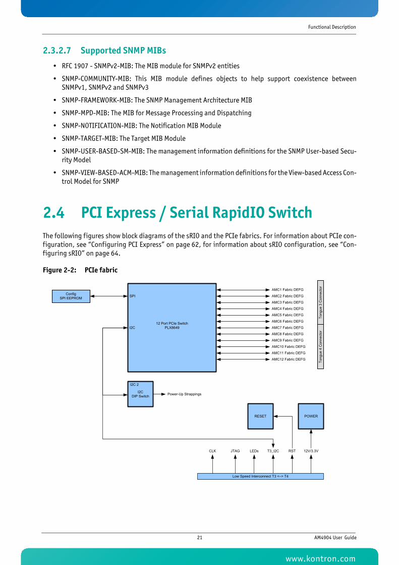
2.4 PCI Express / Serial RapidIO SwitchThe following figures show block diagrams of the sRIO and the PCIe fabrics. For information about PCIe con-figuration, see “Configuring PCI Express” on page 62, for information about sRIO configuration, see “Con-figuring sRIO” on page 64.
Figure 2-2: PCIe fabric
12 Port PCIe Switch PLX8649I2C
AMC1 Fabric DEFG
AMC2 Fabric DEFG
AMC3 Fabric DEFG
AMC5 Fabric DEFG
AMC6 Fabric DEFG
AMC4 Fabric DEFG
AMC7 Fabric DEFG
AMC8 Fabric DEFG
AMC9 Fabric DEFG
AMC11 Fabric DEFG
AMC12 Fabric DEFG
AMC10 Fabric DEFG
ConfigSPI EEPROM SPI
I2CDIP Switch
I2C 2
Power-Up Strappings
Tong
ue 3
Con
nect
orTo
ngue
4 C
onne
ctor
Low Speed Interconnect T3 <–> T4
JTAG LEDs T3_I2C 12V/3.3VRSTCLK
RESET POWER
21 AM4904 User Guide
www.kontron.com
Functional Description
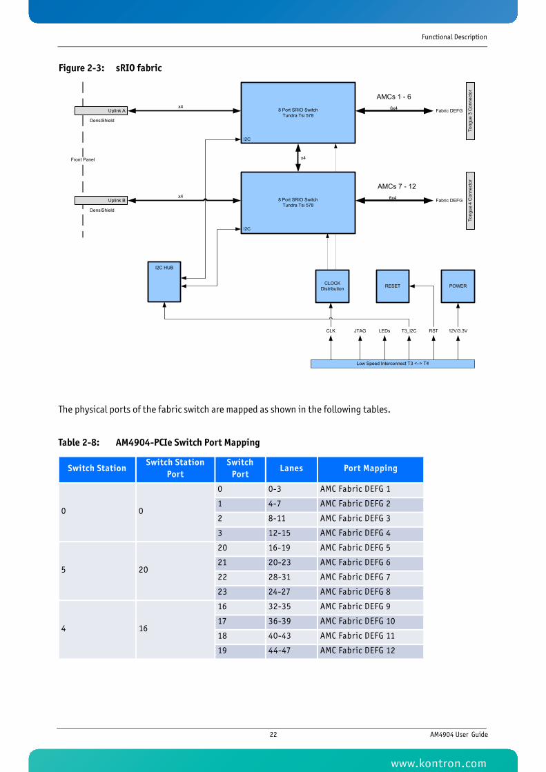
Figure 2-3: sRIO fabric
The physical ports of the fabric switch are mapped as shown in the following tables.
Table 2-8: AM4904-PCIe Switch Port Mapping
Switch StationSwitch Station
PortSwitch
PortLanes Port Mapping
0 0
0 0-3 AMC Fabric DEFG 1
1 4-7 AMC Fabric DEFG 2
2 8-11 AMC Fabric DEFG 3
3 12-15 AMC Fabric DEFG 4
5 20
20 16-19 AMC Fabric DEFG 5
21 20-23 AMC Fabric DEFG 6
22 28-31 AMC Fabric DEFG 7
23 24-27 AMC Fabric DEFG 8
4 16
16 32-35 AMC Fabric DEFG 9
17 36-39 AMC Fabric DEFG 10
18 40-43 AMC Fabric DEFG 11
19 44-47 AMC Fabric DEFG 12
I2C
8 Port SRIO Switch Tundra Tsi 578
I2C
Fabric DEFG
Fabric DEFG
Tong
ue 3
Con
nect
orTo
ngue
4 C
onne
ctor
I2C HUB
8 Port SRIO Switch Tundra Tsi 578
I2C
6x4
6x4x4
x4
x4
DensiShield
DensiShield
Low Speed Interconnect T3 <–> T4
JTAG LEDs T3_I2C 12V/3.3VRSTCLK
Front Panel
Uplink A
Uplink B
CLOCKDistribution RESET POWER
AMCs 1 - 6
AMCs 7 - 12
22 AM4904 User Guide
www.kontron.com
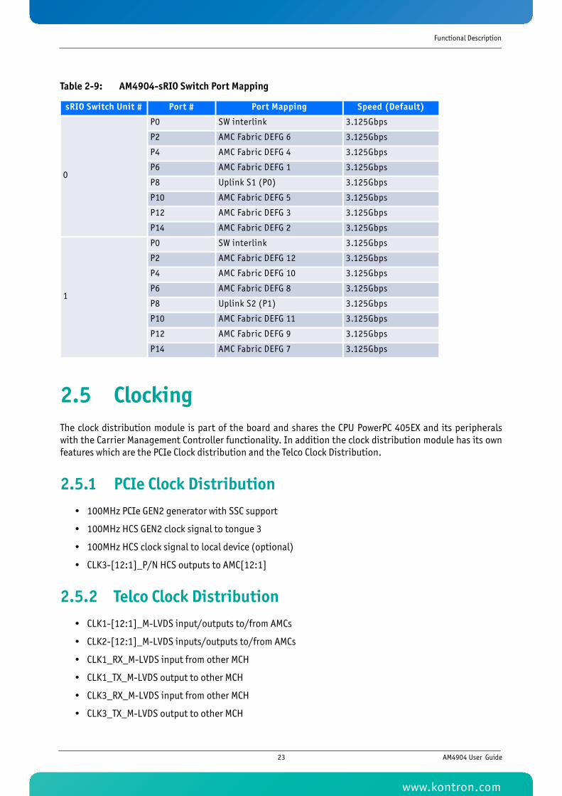
Functional Description
2.5 ClockingThe clock distribution module is part of the board and shares the CPU PowerPC 405EX and its peripheralswith the Carrier Management Controller functionality. In addition the clock distribution module has its ownfeatures which are the PCIe Clock distribution and the Telco Clock Distribution.
2.5.1 PCIe Clock Distribution• 100MHz PCIe GEN2 generator with SSC support
• 100MHz HCS GEN2 clock signal to tongue 3
• 100MHz HCS clock signal to local device (optional)
• CLK3-[12:1]_P/N HCS outputs to AMC[12:1]
2.5.2 Telco Clock Distribution• CLK1-[12:1]_M-LVDS input/outputs to/from AMCs
• CLK2-[12:1]_M-LVDS inputs/outputs to/from AMCs
• CLK1_RX_M-LVDS input from other MCH
• CLK1_TX_M-LVDS output to other MCH
• CLK3_RX_M-LVDS input from other MCH
• CLK3_TX_M-LVDS output to other MCH
Table 2-9: AM4904-sRIO Switch Port Mapping
sRIO Switch Unit # Port # Port Mapping Speed (Default)
0
P0 SW interlink 3.125Gbps
P2 AMC Fabric DEFG 6 3.125Gbps
P4 AMC Fabric DEFG 4 3.125Gbps
P6 AMC Fabric DEFG 1 3.125Gbps
P8 Uplink S1 (P0) 3.125Gbps
P10 AMC Fabric DEFG 5 3.125Gbps
P12 AMC Fabric DEFG 3 3.125Gbps
P14 AMC Fabric DEFG 2 3.125Gbps
1
P0 SW interlink 3.125Gbps
P2 AMC Fabric DEFG 12 3.125Gbps
P4 AMC Fabric DEFG 10 3.125Gbps
P6 AMC Fabric DEFG 8 3.125Gbps
P8 Uplink S2 (P1) 3.125Gbps
P10 AMC Fabric DEFG 11 3.125Gbps
P12 AMC Fabric DEFG 9 3.125Gbps
P14 AMC Fabric DEFG 7 3.125Gbps
23 AM4904 User Guide
www.kontron.com
Functional Description
• Zarlink ZL30143 SyncE 10GE/GE/SONET/SDH G.8262/Stratum 3 System Synchronizer/Sets PLL
• Stratum 3 Accuracy
• Long Term Accuracy (20 years): ±4.6 ppm
• Short Term Stability (24 hours): ±0.37 ppm
• Frequency Drift Rate: ±4.63x10e-13
• SONET/SDH/PDH System Timing Module
• Input references from BITS input, other MCH or AMC
• 1 PPS
• 2 KHz
• 8 KHz, and multiple of 8 kHz up to 77.76MHz
• 1.544 MHz
• 2.048 MHz
• 8.192 MHz
• 16.384 MHz
• 19.44 MHz
• 25 MHz
• 62.5 MHz
• 125 MHz
• 155.52 MHz
• 10 MHz
• Input reference monitoring for frequency and phase irregularities
• Output frequencies 8kHz, 1.544MHz, 2.048MHz, 19.44MHz and multiples of 8kHz up to 100MHz
• Hardware quality level of GR-1244 Stratum 3
• Module supports free-run, hold-over and phase-locked
• Meets jitter, wander, holdover and other performance specifications detailed in Telecordia GR-253-CORE (SONET) or ITU-T G.813 (SDH)
• The input voltage range is from 0V to 5V with a minimum input level of 300mVpp. The input is ACcoupled
• The SMA input is terminated with 50 Ohm
• Synchronous Ethernet System Timing Module
• Synchronizes to 25MHz, recovered clock from local front-uplink Ethernet PHYs
• Transmits 25MHZ to local PHYs and switch silicon reference clock
• G.8262
2.6 Board InterfacesThe AM4904 has following front panel interfaces:
• 10/100Base-T Management Port with LEDs
• Serial RS232 Interface
• BITS Clock Input (CLK)
• Dual 10/100/1000Base-T Uplink (GbE1, GbE2) with LEDs
24 AM4904 User Guide
www.kontron.com
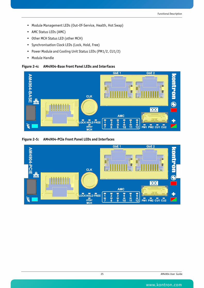
Functional Description
• Module Management LEDs (Out-Of-Service, Health, Hot Swap)
• AMC Status LEDs (AMC)
• Other MCH Status LED (other MCH)
• Synchronisation Clock LEDs (Lock, Hold, Free)
• Power Module and Cooling Unit Status LEDs (PM1/2, CU1/2)
• Module Handle
Figure 2-4: AM4904-Base Front Panel LEDs and Interfaces
Figure 2-5: AM4904-PCIe Front Panel LEDs and Interfaces
25 AM4904 User Guide
www.kontron.com
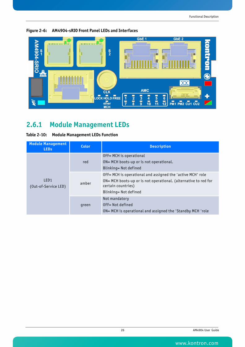
Functional Description
Figure 2-6: AM4904-sRIO Front Panel LEDs and Interfaces
2.6.1 Module Management LEDsTable 2-10: Module Management LEDs Function
Module Management LEDs
Color Description
LED1
(Out-of-Service LED)
red
OFF= MCH is operational
ON= MCH boots-up or is not operational.
Blinking= Not def ined
amber
OFF= MCH is operational and assigned the 'active MCH' role
ON= MCH boots-up or is not operational. (alternative to red for certain countries)
Blinking= Not def ined
green
Not mandatory
OFF= Not defined
ON= MCH is operational and assigned the 'Standby MCH 'role
26 AM4904 User Guide
www.kontron.com
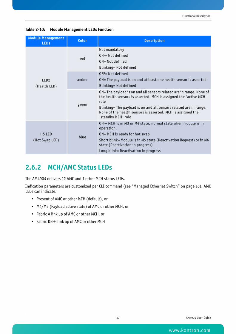
Functional Description
2.6.2 MCH/AMC Status LEDsThe AM4904 delivers 12 AMC and 1 other MCH status LEDs.
Indication parameters are customized per CLI command (see “Managed Ethernet Switch” on page 16). AMCLEDs can indicate:
• Present of AMC or other MCH (default), or
• M4/M5 (Payload active state) of AMC or other MCH, or
• Fabric A link up of AMC or other MCH, or
• Fabric DEFG link up of AMC or other MCH
LED2
(Health LED)
red
Not mandatory
OFF= Not defined
ON= Not defined
Blinking= Not def ined
amber
OFF= Not defined
ON= The payload is on and at least one health sensor is asserted
Blinking= Not def ined
green
ON= The payload is on and all sensors related are in range. None of the health sensors is asserted. MCH is assigned the 'active MCH' role
Blinking= The payload is on and all sensors related are in range. None of the health sensors is asserted. MCH is assigned the 'standby MCH' role
HS LED
(Hot Swap LED)blue
OFF= MCH is in M3 or M4 state, normal state when module is in operation.
ON= MCH is ready for hot swap
Short blink= Module is in M5 state (Deactivation Request) or in M6 state (Deactivation in progress)
Long blink= Deactivation in progress
Table 2-10: Module Management LEDs Function
Module Management LEDs
Color Description
27 AM4904 User Guide
www.kontron.com
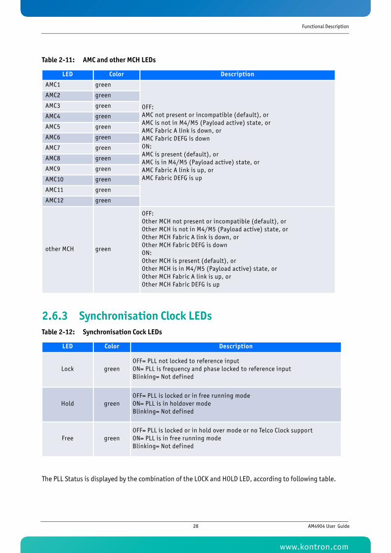
Functional Description
2.6.3 Synchronisation Clock LEDs
The PLL Status is displayed by the combination of the LOCK and HOLD LED, according to following table.
Table 2-11: AMC and other MCH LEDs
LED Color Description
AMC1 green
OFF: AMC not present or incompatible (default), orAMC is not in M4/M5 (Payload active) state, orAMC Fabric A link is down, orAMC Fabric DEFG is downON: AMC is present (default), orAMC is in M4/M5 (Payload active) state, orAMC Fabric A link is up, orAMC Fabric DEFG is up
AMC2 green
AMC3 green
AMC4 green
AMC5 green
AMC6 green
AMC7 green
AMC8 green
AMC9 green
AMC10 green
AMC11 green
AMC12 green
other MCH green
OFF: Other MCH not present or incompatible (default), orOther MCH is not in M4/M5 (Payload active) state, orOther MCH Fabric A link is down, orOther MCH Fabric DEFG is downON: Other MCH is present (default), orOther MCH is in M4/M5 (Payload active) state, orOther MCH Fabric A link is up, orOther MCH Fabric DEFG is up
Table 2-12: Synchronisation Cock LEDs
LED Color Description
Lock greenOFF= PLL not locked to reference input ON= PLL is frequency and phase locked to reference input Blinking= Not defined
Hold greenOFF= PLL is locked or in free running mode ON= PLL is in holdover mode Blinking= Not defined
Free greenOFF= PLL is locked or in hold over mode or no Telco Clock support ON= PLL is in free running modeBlinking= Not defined
28 AM4904 User Guide
www.kontron.com
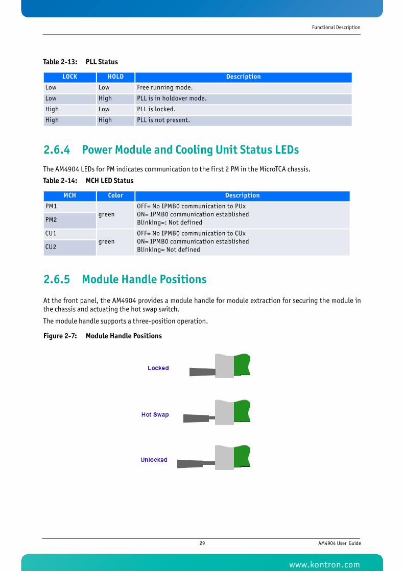
Functional Description
2.6.4 Power Module and Cooling Unit Status LEDsThe AM4904 LEDs for PM indicates communication to the first 2 PM in the MicroTCA chassis.
2.6.5 Module Handle Positions
At the front panel, the AM4904 provides a module handle for module extraction for securing the module inthe chassis and actuating the hot swap switch.
The module handle supports a three-position operation.
Figure 2-7: Module Handle Positions
Table 2-13: PLL Status
LOCK HOLD Description
Low Low Free running mode.
Low High PLL is in holdover mode.
High Low PLL is locked.
High High PLL is not present.
Table 2-14: MCH LED Status
MCH Color Description
PM1green
OFF= No IPMB0 communication to PUxON= IPMB0 communication establishedBlinking=: Not definedPM2
CU1green
OFF= No IPMB0 communication to CUxON= IPMB0 communication establishedBlinking= Not definedCU2
29 AM4904 User Guide
www.kontron.com
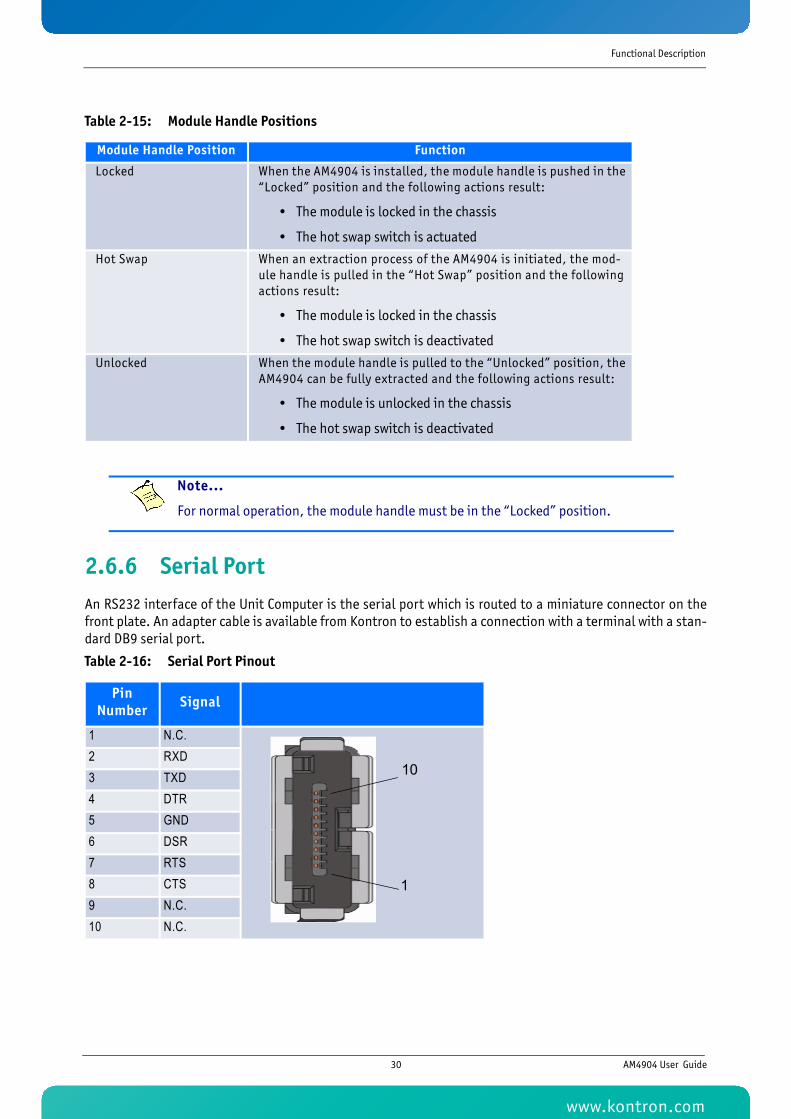
Functional Description
2.6.6 Serial PortAn RS232 interface of the Unit Computer is the serial port which is routed to a miniature connector on thefront plate. An adapter cable is available from Kontron to establish a connection with a terminal with a stan-dard DB9 serial port.
UNCTION I/O
Table 2-15: Module Handle Positions
Module Handle Position Function
Locked When the AM4904 is installed, the module handle is pushed in the “Locked” position and the following actions result:
• The module is locked in the chassis
• The hot swap switch is actuated
Hot Swap When an extraction process of the AM4904 is initiated, the mod-ule handle is pulled in the “Hot Swap” position and the following actions result:
• The module is locked in the chassis
• The hot swap switch is deactivated
Unlocked When the module handle is pulled to the “Unlocked” position, the AM4904 can be fully extracted and the following actions result:
• The module is unlocked in the chassis
• The hot swap switch is deactivated
Note...
For normal operation, the module handle must be in the “Locked” position.
Table 2-16: Serial Port Pinout
Pin Number Signal
1 N.C.2 RXD3 TXD4 DTR5 GND6 DSR7 RTS8 CTS9 N.C.10 N.C.
10
1
30 AM4904 User Guide
www.kontron.com
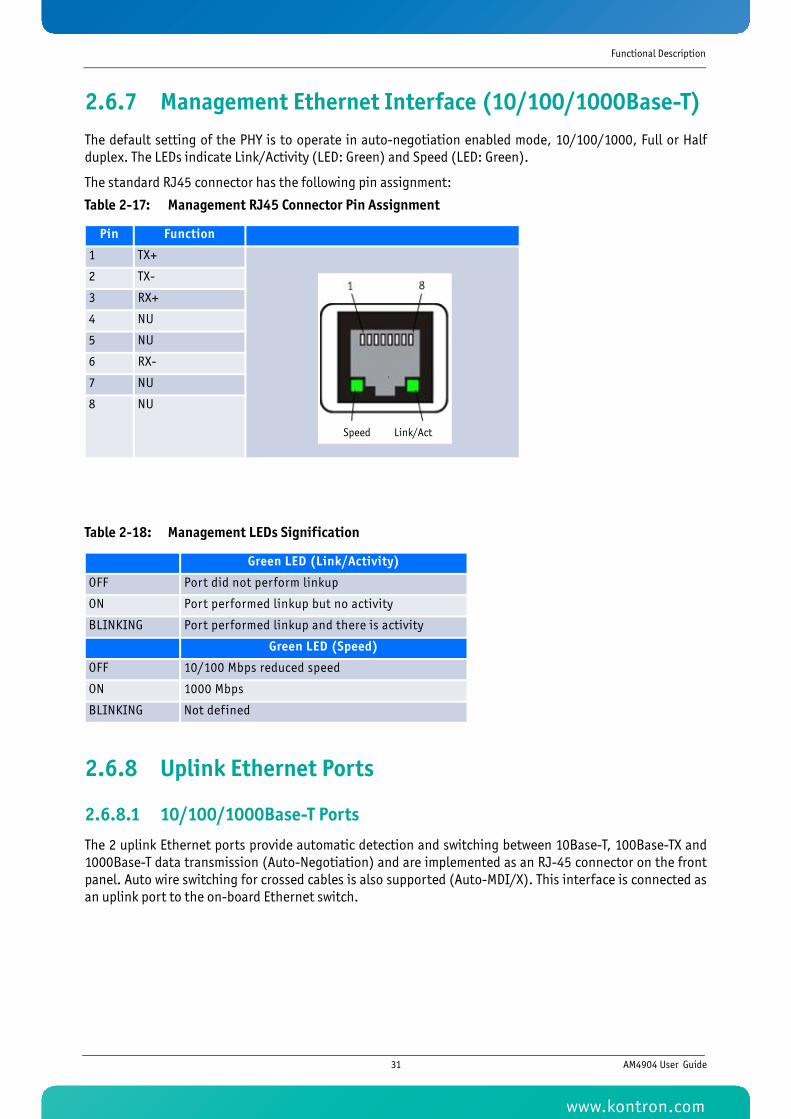
Functional Description
2.6.7 Management Ethernet Interface (10/100/1000Base-T)The default setting of the PHY is to operate in auto-negotiation enabled mode, 10/100/1000, Full or Halfduplex. The LEDs indicate Link/Activity (LED: Green) and Speed (LED: Green).
The standard RJ45 connector has the following pin assignment:
2.6.8 Uplink Ethernet Ports
2.6.8.1 10/100/1000Base-T Ports
The 2 uplink Ethernet ports provide automatic detection and switching between 10Base-T, 100Base-TX and1000Base-T data transmission (Auto-Negotiation) and are implemented as an RJ-45 connector on the frontpanel. Auto wire switching for crossed cables is also supported (Auto-MDI/X). This interface is connected asan uplink port to the on-board Ethernet switch.
Table 2-17: Management RJ45 Connector Pin Assignment
Pin Function
1 TX+
2 TX-
3 RX+
4 NU
5 NU
6 RX-
7 NU
8 NU
Table 2-18: Management LEDs Signification
Green LED (Link/Activity)
OFF Port did not perform linkup
ON Port performed linkup but no activity
BLINKING Port performed linkup and there is activity
Green LED (Speed)
OFF 10/100 Mbps reduced speed
ON 1000 Mbps
BLINKING Not defined
Speed Link/Act
31 AM4904 User Guide
www.kontron.com
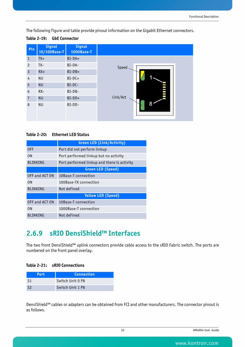
Functional Description
The following figure and table provide pinout information on the Gigabit Ethernet connectors.
Table 2-19: GbE Connector
Table 2-20: Ethernet LED Status
2.6.9 sRIO DensiShield™ InterfacesThe two front DensiShield™ uplink connectors provide cable access to the sRIO Fabric switch. The ports arenumbered on the front panel overlay.
DensiShield™ cables or adapters can be obtained from FCI and other manufacturers. The connector pinout isas follows.
PinSignal
10/100Base-TSignal
1000Base-T
1 TX+ BI-DA+
2 TX- BI-DA-
3 RX+ BI-DB+
4 NU BI-DC+
5 NU BI-DC-
6 RX- BI-DB-
7 NU BI-DD+
8 NU BI-DD-
Green LED (Link/Activity)
OFF Port did not perform linkup
ON Port performed linkup but no activity
BLINKING Port performed linkup and there is activity
Green LED (Speed)
OFF and ACT ON 10Base-T connection
ON 100Base-TX connection
BLINKING Not defined
Yellow LED (Speed)
OFF and ACT ON 10Base-T connection
ON 1000Base-T connection
BLINKING Not defined
Table 2-21: sRIO Connections
Port Connection
S1 Switch Unit 0 P8
S2 Switch Unit 1 P8
Speed
Link/Act
32 AM4904 User Guide
www.kontron.com
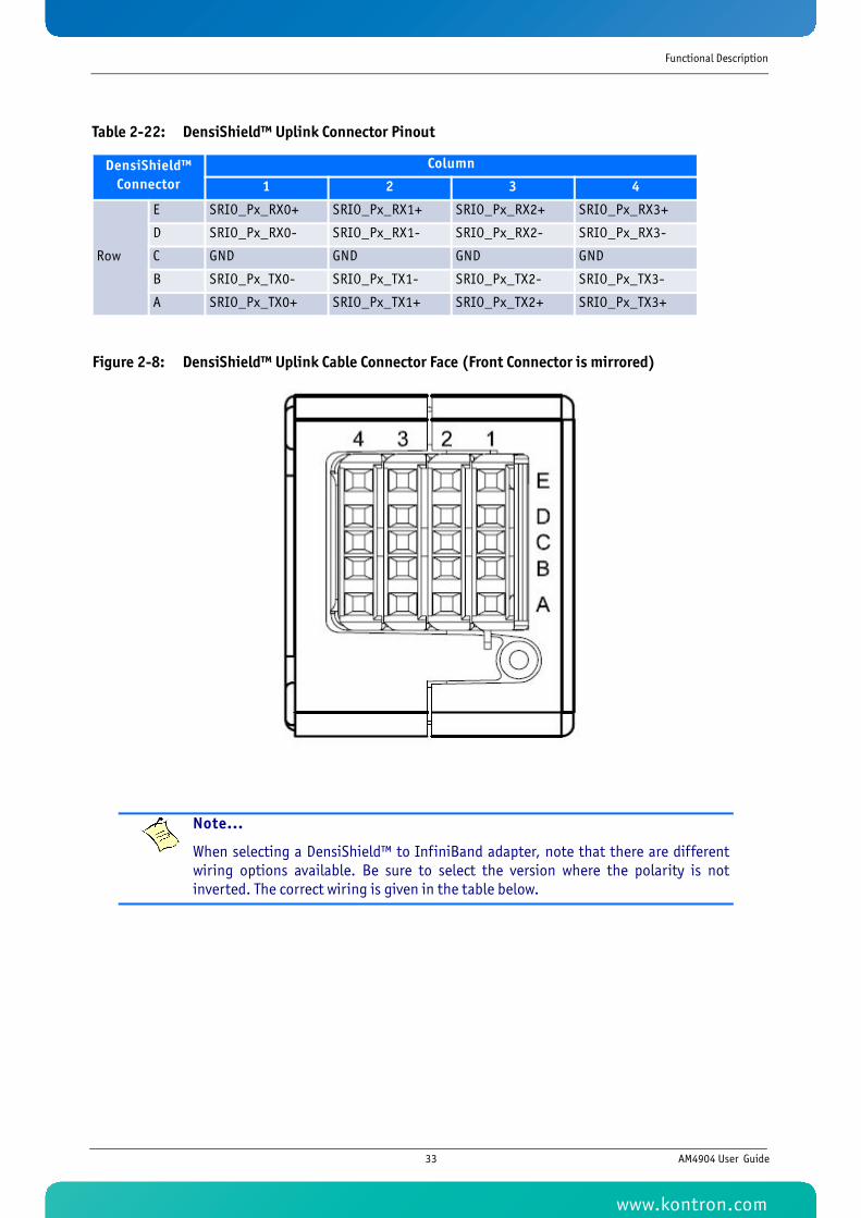
Functional Description
Figure 2-8: DensiShield™ Uplink Cable Connector Face (Front Connector is mirrored)
Table 2-22: DensiShield™ Uplink Connector Pinout
DensiShield™ Connector
Column
1 2 3 4
Row
E SRIO_Px_RX0+ SRIO_Px_RX1+ SRIO_Px_RX2+ SRIO_Px_RX3+
D SRIO_Px_RX0- SRIO_Px_RX1- SRIO_Px_RX2- SRIO_Px_RX3-
C GND GND GND GND
B SRIO_Px_TX0- SRIO_Px_TX1- SRIO_Px_TX2- SRIO_Px_TX3-
A SRIO_Px_TX0+ SRIO_Px_TX1+ SRIO_Px_TX2+ SRIO_Px_TX3+
Note...
When selecting a DensiShield™ to InfiniBand adapter, note that there are differentwiring options available. Be sure to select the version where the polarity is notinverted. The correct wiring is given in the table below.
33 AM4904 User Guide
www.kontron.com
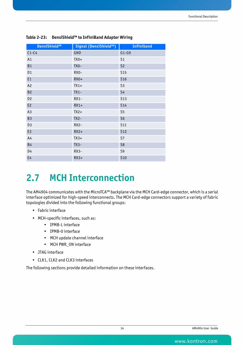
Functional Description
2.7 MCH InterconnectionThe AM4904 communicates with the MicroTCA™ backplane via the MCH Card-edge connector, which is a serialinterface optimized for high-speed interconnects. The MCH Card-edge connectors support a variety of fabrictopologies divided into the following functional groups:
• Fabric interface
• MCH-specific interfaces, such as:
• IPMB-L interface
• IPMB-0 interface
• MCH update channel interface
• MCH PWR_ON interface
• JTAG interface
• CLK1, CLK2 and CLK3 interfaces
The following sections provide detailed information on these interfaces.
Table 2-23: DensiShield™ to InfiniBand Adapter Wiring
DensiShield™ Signal (DensiShield™) Infiniband
C1-C4 GND G1-G9
A1 TX0+ S1
B1 TX0- S2
D1 RX0- S15
E1 RX0+ S16
A2 TX1+ S3
B2 TX1- S4
D2 RX1- S13
E2 RX1+ S14
A3 TX2+ S5
B3 TX2- S6
D3 RX2- S11
E3 RX2+ S12
A4 TX3+ S7
B4 TX3- S8
D4 RX3- S9
E4 RX3+ S10
34 AM4904 User Guide
www.kontron.com
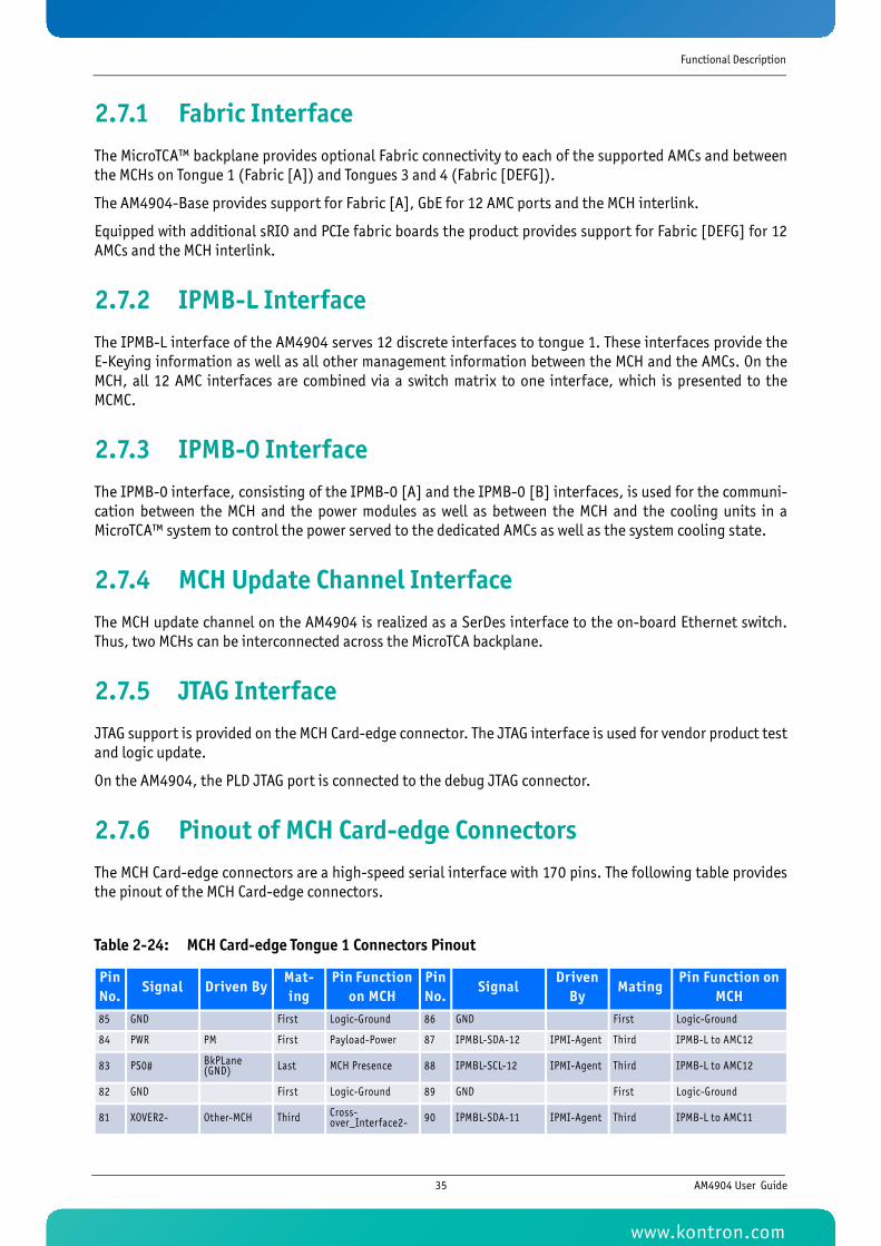
Functional Description
2.7.1 Fabric InterfaceThe MicroTCA™ backplane provides optional Fabric connectivity to each of the supported AMCs and betweenthe MCHs on Tongue 1 (Fabric [A]) and Tongues 3 and 4 (Fabric [DEFG]).
The AM4904-Base provides support for Fabric [A], GbE for 12 AMC ports and the MCH interlink.
Equipped with additional sRIO and PCIe fabric boards the product provides support for Fabric [DEFG] for 12AMCs and the MCH interlink.
2.7.2 IPMB-L InterfaceThe IPMB-L interface of the AM4904 serves 12 discrete interfaces to tongue 1. These interfaces provide theE-Keying information as well as all other management information between the MCH and the AMCs. On theMCH, all 12 AMC interfaces are combined via a switch matrix to one interface, which is presented to theMCMC.
2.7.3 IPMB-0 InterfaceThe IPMB-0 interface, consisting of the IPMB-0 [A] and the IPMB-0 [B] interfaces, is used for the communi-cation between the MCH and the power modules as well as between the MCH and the cooling units in aMicroTCA™ system to control the power served to the dedicated AMCs as well as the system cooling state.
2.7.4 MCH Update Channel InterfaceThe MCH update channel on the AM4904 is realized as a SerDes interface to the on-board Ethernet switch.Thus, two MCHs can be interconnected across the MicroTCA backplane.
2.7.5 JTAG InterfaceJTAG support is provided on the MCH Card-edge connector. The JTAG interface is used for vendor product testand logic update.
On the AM4904, the PLD JTAG port is connected to the debug JTAG connector.
2.7.6 Pinout of MCH Card-edge ConnectorsThe MCH Card-edge connectors are a high-speed serial interface with 170 pins. The following table providesthe pinout of the MCH Card-edge connectors.
Table 2-24: MCH Card-edge Tongue 1 Connectors Pinout
Pin No.
Signal Driven ByMat-ing
Pin Function on MCH
Pin No.
SignalDriven
ByMating
Pin Function on MCH
85 GND First Logic-Ground 86 GND First Logic-Ground
84 PWR PM First Payload-Power 87 IPMBL-SDA-12 IPMI-Agent Third IPMB-L to AMC12
83 PS0# BkPLane (GND) Last MCH Presence 88 IPMBL-SCL-12 IPMI-Agent Third IPMB-L to AMC12
82 GND First Logic-Ground 89 GND First Logic-Ground
81 XOVER2- Other-MCH Third Cross-over_Interface2- 90 IPMBL-SDA-11 IPMI-Agent Third IPMB-L to AMC11
35 AM4904 User Guide
www.kontron.com
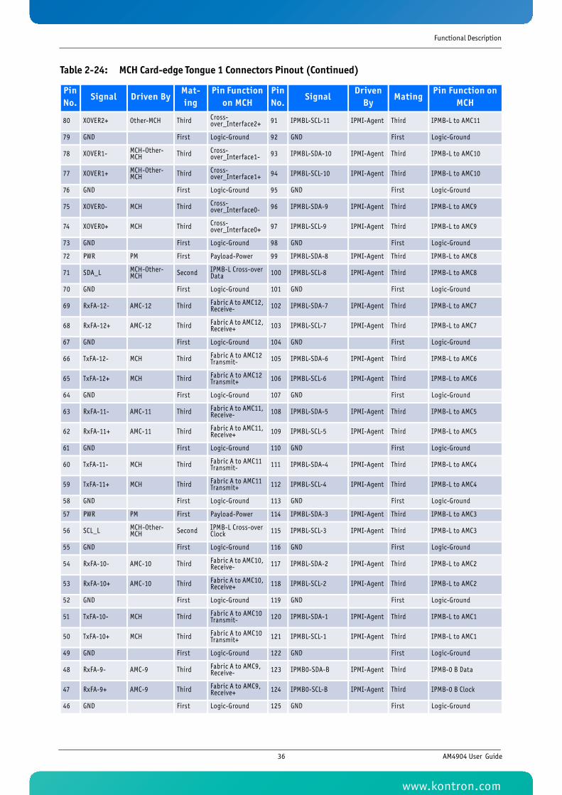
Functional Description
80 XOVER2+ Other-MCH Third Cross-over_Interface2+ 91 IPMBL-SCL-11 IPMI-Agent Third IPMB-L to AMC11
79 GND First Logic-Ground 92 GND First Logic-Ground
78 XOVER1- MCH-Other-MCH Third Cross-
over_Interface1- 93 IPMBL-SDA-10 IPMI-Agent Third IPMB-L to AMC10
77 XOVER1+ MCH-Other-MCH Third Cross-
over_Interface1+ 94 IPMBL-SCL-10 IPMI-Agent Third IPMB-L to AMC10
76 GND First Logic-Ground 95 GND First Logic-Ground
75 XOVER0- MCH Third Cross-over_Interface0- 96 IPMBL-SDA-9 IPMI-Agent Third IPMB-L to AMC9
74 XOVER0+ MCH Third Cross-over_Interface0+ 97 IPMBL-SCL-9 IPMI-Agent Third IPMB-L to AMC9
73 GND First Logic-Ground 98 GND First Logic-Ground
72 PWR PM First Payload-Power 99 IPMBL-SDA-8 IPMI-Agent Third IPMB-L to AMC8
71 SDA_L MCH-Other-MCH Second IPMB-L Cross-over
Data 100 IPMBL-SCL-8 IPMI-Agent Third IPMB-L to AMC8
70 GND First Logic-Ground 101 GND First Logic-Ground
69 RxFA-12- AMC-12 Third Fabric A to AMC12, Receive- 102 IPMBL-SDA-7 IPMI-Agent Third IPMB-L to AMC7
68 RxFA-12+ AMC-12 Third Fabric A to AMC12, Receive+ 103 IPMBL-SCL-7 IPMI-Agent Third IPMB-L to AMC7
67 GND First Logic-Ground 104 GND First Logic-Ground
66 TxFA-12- MCH Third Fabric A to AMC12 Transmit- 105 IPMBL-SDA-6 IPMI-Agent Third IPMB-L to AMC6
65 TxFA-12+ MCH Third Fabric A to AMC12 Transmit+ 106 IPMBL-SCL-6 IPMI-Agent Third IPMB-L to AMC6
64 GND First Logic-Ground 107 GND First Logic-Ground
63 RxFA-11- AMC-11 Third Fabric A to AMC11, Receive- 108 IPMBL-SDA-5 IPMI-Agent Third IPMB-L to AMC5
62 RxFA-11+ AMC-11 Third Fabric A to AMC11, Receive+ 109 IPMBL-SCL-5 IPMI-Agent Third IPMB-L to AMC5
61 GND First Logic-Ground 110 GND First Logic-Ground
60 TxFA-11- MCH Third Fabric A to AMC11 Transmit- 111 IPMBL-SDA-4 IPMI-Agent Third IPMB-L to AMC4
59 TxFA-11+ MCH Third Fabric A to AMC11 Transmit+ 112 IPMBL-SCL-4 IPMI-Agent Third IPMB-L to AMC4
58 GND First Logic-Ground 113 GND First Logic-Ground
57 PWR PM First Payload-Power 114 IPMBL-SDA-3 IPMI-Agent Third IPMB-L to AMC3
56 SCL_L MCH-Other-MCH Second IPMB-L Cross-over
Clock 115 IPMBL-SCL-3 IPMI-Agent Third IPMB-L to AMC3
55 GND First Logic-Ground 116 GND First Logic-Ground
54 RxFA-10- AMC-10 Third Fabric A to AMC10, Receive- 117 IPMBL-SDA-2 IPMI-Agent Third IPMB-L to AMC2
53 RxFA-10+ AMC-10 Third Fabric A to AMC10, Receive+ 118 IPMBL-SCL-2 IPMI-Agent Third IPMB-L to AMC2
52 GND First Logic-Ground 119 GND First Logic-Ground
51 TxFA-10- MCH Third Fabric A to AMC10 Transmit- 120 IPMBL-SDA-1 IPMI-Agent Third IPMB-L to AMC1
50 TxFA-10+ MCH Third Fabric A to AMC10 Transmit+ 121 IPMBL-SCL-1 IPMI-Agent Third IPMB-L to AMC1
49 GND First Logic-Ground 122 GND First Logic-Ground
48 RxFA-9- AMC-9 Third Fabric A to AMC9, Receive- 123 IPMB0-SDA-B IPMI-Agent Third IPMB-0 B Data
47 RxFA-9+ AMC-9 Third Fabric A to AMC9, Receive+ 124 IPMB0-SCL-B IPMI-Agent Third IPMB-0 B Clock
46 GND First Logic-Ground 125 GND First Logic-Ground
Table 2-24: MCH Card-edge Tongue 1 Connectors Pinout (Continued)
Pin No.
Signal Driven ByMat-ing
Pin Function on MCH
Pin No.
SignalDriven
ByMating
Pin Function on MCH
36 AM4904 User Guide
www.kontron.com
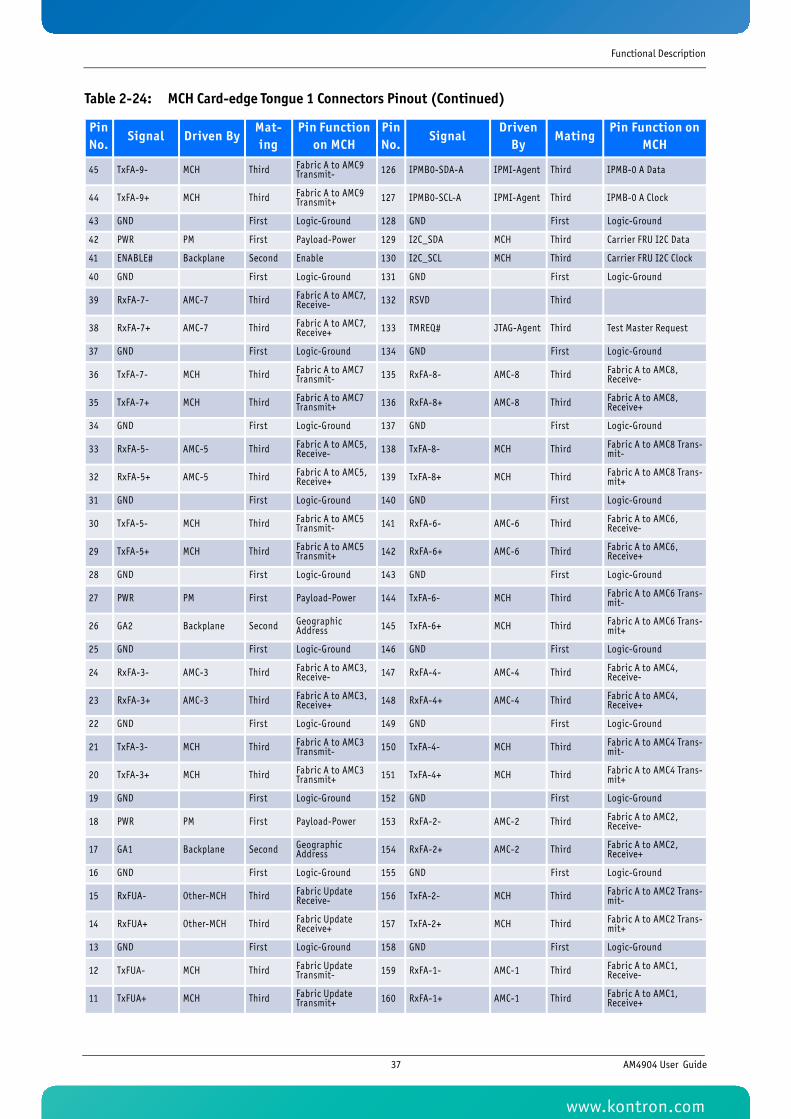
Functional Description
45 TxFA-9- MCH Third Fabric A to AMC9 Transmit- 126 IPMB0-SDA-A IPMI-Agent Third IPMB-0 A Data
44 TxFA-9+ MCH Third Fabric A to AMC9 Transmit+ 127 IPMB0-SCL-A IPMI-Agent Third IPMB-0 A Clock
43 GND First Logic-Ground 128 GND First Logic-Ground
42 PWR PM First Payload-Power 129 I2C_SDA MCH Third Carrier FRU I2C Data
41 ENABLE# Backplane Second Enable 130 I2C_SCL MCH Third Carrier FRU I2C Clock
40 GND First Logic-Ground 131 GND First Logic-Ground
39 RxFA-7- AMC-7 Third Fabric A to AMC7, Receive- 132 RSVD Third
38 RxFA-7+ AMC-7 Third Fabric A to AMC7, Receive+ 133 TMREQ# JTAG-Agent Third Test Master Request
37 GND First Logic-Ground 134 GND First Logic-Ground
36 TxFA-7- MCH Third Fabric A to AMC7 Transmit- 135 RxFA-8- AMC-8 Third Fabric A to AMC8,
Receive-
35 TxFA-7+ MCH Third Fabric A to AMC7 Transmit+ 136 RxFA-8+ AMC-8 Third Fabric A to AMC8,
Receive+
34 GND First Logic-Ground 137 GND First Logic-Ground
33 RxFA-5- AMC-5 Third Fabric A to AMC5, Receive- 138 TxFA-8- MCH Third Fabric A to AMC8 Trans-
mit-
32 RxFA-5+ AMC-5 Third Fabric A to AMC5, Receive+ 139 TxFA-8+ MCH Third Fabric A to AMC8 Trans-
mit+
31 GND First Logic-Ground 140 GND First Logic-Ground
30 TxFA-5- MCH Third Fabric A to AMC5 Transmit- 141 RxFA-6- AMC-6 Third Fabric A to AMC6,
Receive-
29 TxFA-5+ MCH Third Fabric A to AMC5 Transmit+ 142 RxFA-6+ AMC-6 Third Fabric A to AMC6,
Receive+
28 GND First Logic-Ground 143 GND First Logic-Ground
27 PWR PM First Payload-Power 144 TxFA-6- MCH Third Fabric A to AMC6 Trans-mit-
26 GA2 Backplane Second Geographic Address 145 TxFA-6+ MCH Third Fabric A to AMC6 Trans-
mit+
25 GND First Logic-Ground 146 GND First Logic-Ground
24 RxFA-3- AMC-3 Third Fabric A to AMC3, Receive- 147 RxFA-4- AMC-4 Third Fabric A to AMC4,
Receive-
23 RxFA-3+ AMC-3 Third Fabric A to AMC3, Receive+ 148 RxFA-4+ AMC-4 Third Fabric A to AMC4,
Receive+
22 GND First Logic-Ground 149 GND First Logic-Ground
21 TxFA-3- MCH Third Fabric A to AMC3 Transmit- 150 TxFA-4- MCH Third Fabric A to AMC4 Trans-
mit-
20 TxFA-3+ MCH Third Fabric A to AMC3 Transmit+ 151 TxFA-4+ MCH Third Fabric A to AMC4 Trans-
mit+
19 GND First Logic-Ground 152 GND First Logic-Ground
18 PWR PM First Payload-Power 153 RxFA-2- AMC-2 Third Fabric A to AMC2, Receive-
17 GA1 Backplane Second Geographic Address 154 RxFA-2+ AMC-2 Third Fabric A to AMC2,
Receive+
16 GND First Logic-Ground 155 GND First Logic-Ground
15 RxFUA- Other-MCH Third Fabric Update Receive- 156 TxFA-2- MCH Third Fabric A to AMC2 Trans-
mit-
14 RxFUA+ Other-MCH Third Fabric Update Receive+ 157 TxFA-2+ MCH Third Fabric A to AMC2 Trans-
mit+
13 GND First Logic-Ground 158 GND First Logic-Ground
12 TxFUA- MCH Third Fabric Update Transmit- 159 RxFA-1- AMC-1 Third Fabric A to AMC1,
Receive-
11 TxFUA+ MCH Third Fabric Update Transmit+ 160 RxFA-1+ AMC-1 Third Fabric A to AMC1,
Receive+
Table 2-24: MCH Card-edge Tongue 1 Connectors Pinout (Continued)
Pin No.
Signal Driven ByMat-ing
Pin Function on MCH
Pin No.
SignalDriven
ByMating
Pin Function on MCH
37 AM4904 User Guide
www.kontron.com
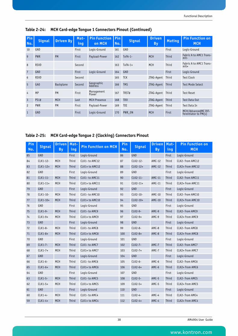
Functional Description
10 GND First Logic-Ground 161 GND First Logic-Ground
9 PWR PM First Payload-Power 162 TxFA-1- MCH Third Fabric A to AMC1 Trans-mit-
8 RSVD Second 163 TxFA-1+ MCH Third Fabric A to AMC1 Trans-mit+
7 GND First Logic-Ground 164 GND First Logic-Ground
6 RSVD Second 165 TCK JTAG-Agent Third Test Clock
5 GA0 Backplane Second Geographic Address 166 TMS JTAG-Agent Third Test Mode Select
4 MP PM First Management Power 167 TRST# JTAG-Agent Third Test Reset
3 PS1# MCH Last MCH Presence 168 TDO JTAG-Agent Third Test Data Out
2 PWR PM First Payload-Power 169 TDI JTAG-Agent Third Test Data In
1 GND First Logic-Ground 170 PWR_ON MCH First MCH/AdvancedMC Dif-ferentiator to PM(s)
Table 2-25: MCH Card-edge Tongue 2 (Clocking) Connectors Pinout
Pin No.
SignalDriven
ByMat-ing
Pin Function on MCHPin No.
SignalDriven
ByMat-ing
Pin Function on MCH
85 GND First Logic-Ground 86 GND First Logic-Ground
84 CLK1-12- MCH Third CLK1- to AMC12 87 CLK2-12- AMC-12 Third CLK2- from AMC12
83 CLK1-12+ MCH Third CLK1+ to AMC12 88 CLK2-12+ AMC-12 Third CLK2+ from AMC12
82 GND First Logic-Ground 89 GND First Logic-Ground
81 CLK1-11- MCH Third CLK1- to AMC11 90 CLK2-11- AMC-11 Third CLK2- from AMC11
80 CLK1-11+ MCH Third CLK1+ to AMC11 91 CLK2-11+ AMC-11 Third CLK2+ from AMC11
79 GND First Logic-Ground 92 GND First Logic-Ground
78 CLK1-10- MCH Third CLK1- to AMC10 93 CLK2-10- AMC-10 Third CLK2- from AMC10
77 CLK1-10+ MCH Third CLK1+ to AMC10 94 CLK2-10+ AMC-10 Third CLK2+ from AMC10
76 GND First Logic-Ground 95 GND First Logic-Ground
75 CLK1-9- MCH Third CLK1- to AMC9 96 CLK2-9- AMC-9 Third CLK2- from AMC9
74 CLK1-9+ MCH Third CLK1+ to AMC9 97 CLK2-9+ AMC-9 Third CLK2+ from AMC9
73 GND First Logic-Ground 98 GND First Logic-Ground
72 CLK1-8- MCH Third CLK1- to AMC8 99 CLK2-8- AMC-8 Third CLK2- from AMC8
71 CLK1-8+ MCH Third CLK1+ to AMC8 100 CLK2-8+ AMC-8 Third CLK2+ from AMC8
70 GND First Logic-Ground 101 GND First Logic-Ground
69 CLK1-7- MCH Third CLK1- to AMC7 102 CLK2-7- AMC-7 Third CLK2- from AMC7
68 CLK1-7+ MCH Third CLK1+ to AMC7 103 CLK2-7+ AMC-7 Third CLK2+ from AMC7
67 GND First Logic-Ground 104 GND First Logic-Ground
66 CLK1-6- MCH Third CLK1- to AMC6 105 CLK2-6- AMC-6 Third CLK2- from AMC6
65 CLK1-6+ MCH Third CLK1+ to AMC6 106 CLK2-6+ AMC-6 Third CLK2+ from AMC6
64 GND First Logic-Ground 107 GND First Logic-Ground
63 CLK1-5- MCH Third CLK1- to AMC5 108 CLK2-5- AMC-5 Third CLK2- from AMC5
62 CLK1-5+ MCH Third CLK1+ to AMC5 109 CLK2-5+ AMC-5 Third CLK2+ from AMC5
61 GND First Logic-Ground 110 GND First Logic-Ground
60 CLK1-4- MCH Third CLK1- to AMC4 111 CLK2-4- AMC-4 Third CLK2- from AMC4
59 CLK1-4+ MCH Third CLK1+ to AMC4 112 CLK2-4+ AMC-4 Third CLK2+ from AMC4
Table 2-24: MCH Card-edge Tongue 1 Connectors Pinout (Continued)
Pin No.
Signal Driven ByMat-ing
Pin Function on MCH
Pin No.
SignalDriven
ByMating
Pin Function on MCH
38 AM4904 User Guide
www.kontron.com
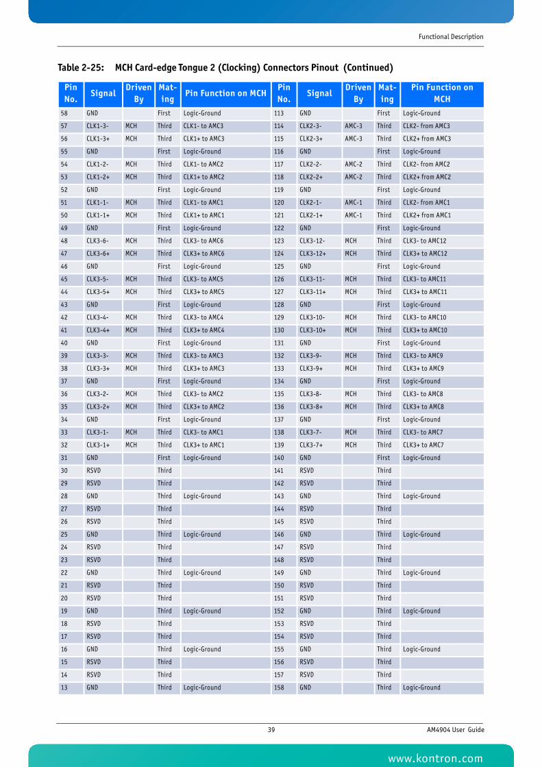
Functional Description
58 GND First Logic-Ground 113 GND First Logic-Ground
57 CLK1-3- MCH Third CLK1- to AMC3 114 CLK2-3- AMC-3 Third CLK2- from AMC3
56 CLK1-3+ MCH Third CLK1+ to AMC3 115 CLK2-3+ AMC-3 Third CLK2+ from AMC3
55 GND First Logic-Ground 116 GND First Logic-Ground
54 CLK1-2- MCH Third CLK1- to AMC2 117 CLK2-2- AMC-2 Third CLK2- from AMC2
53 CLK1-2+ MCH Third CLK1+ to AMC2 118 CLK2-2+ AMC-2 Third CLK2+ from AMC2
52 GND First Logic-Ground 119 GND First Logic-Ground
51 CLK1-1- MCH Third CLK1- to AMC1 120 CLK2-1- AMC-1 Third CLK2- from AMC1
50 CLK1-1+ MCH Third CLK1+ to AMC1 121 CLK2-1+ AMC-1 Third CLK2+ from AMC1
49 GND First Logic-Ground 122 GND First Logic-Ground
48 CLK3-6- MCH Third CLK3- to AMC6 123 CLK3-12- MCH Third CLK3- to AMC12
47 CLK3-6+ MCH Third CLK3+ to AMC6 124 CLK3-12+ MCH Third CLK3+ to AMC12
46 GND First Logic-Ground 125 GND First Logic-Ground
45 CLK3-5- MCH Third CLK3- to AMC5 126 CLK3-11- MCH Third CLK3- to AMC11
44 CLK3-5+ MCH Third CLK3+ to AMC5 127 CLK3-11+ MCH Third CLK3+ to AMC11
43 GND First Logic-Ground 128 GND First Logic-Ground
42 CLK3-4- MCH Third CLK3- to AMC4 129 CLK3-10- MCH Third CLK3- to AMC10
41 CLK3-4+ MCH Third CLK3+ to AMC4 130 CLK3-10+ MCH Third CLK3+ to AMC10
40 GND First Logic-Ground 131 GND First Logic-Ground
39 CLK3-3- MCH Third CLK3- to AMC3 132 CLK3-9- MCH Third CLK3- to AMC9
38 CLK3-3+ MCH Third CLK3+ to AMC3 133 CLK3-9+ MCH Third CLK3+ to AMC9
37 GND First Logic-Ground 134 GND First Logic-Ground
36 CLK3-2- MCH Third CLK3- to AMC2 135 CLK3-8- MCH Third CLK3- to AMC8
35 CLK3-2+ MCH Third CLK3+ to AMC2 136 CLK3-8+ MCH Third CLK3+ to AMC8
34 GND First Logic-Ground 137 GND First Logic-Ground
33 CLK3-1- MCH Third CLK3- to AMC1 138 CLK3-7- MCH Third CLK3- to AMC7
32 CLK3-1+ MCH Third CLK3+ to AMC1 139 CLK3-7+ MCH Third CLK3+ to AMC7
31 GND First Logic-Ground 140 GND First Logic-Ground
30 RSVD Third 141 RSVD Third
29 RSVD Third 142 RSVD Third
28 GND Third Logic-Ground 143 GND Third Logic-Ground
27 RSVD Third 144 RSVD Third
26 RSVD Third 145 RSVD Third
25 GND Third Logic-Ground 146 GND Third Logic-Ground
24 RSVD Third 147 RSVD Third
23 RSVD Third 148 RSVD Third
22 GND Third Logic-Ground 149 GND Third Logic-Ground
21 RSVD Third 150 RSVD Third
20 RSVD Third 151 RSVD Third
19 GND Third Logic-Ground 152 GND Third Logic-Ground
18 RSVD Third 153 RSVD Third
17 RSVD Third 154 RSVD Third
16 GND Third Logic-Ground 155 GND Third Logic-Ground
15 RSVD Third 156 RSVD Third
14 RSVD Third 157 RSVD Third
13 GND Third Logic-Ground 158 GND Third Logic-Ground
Table 2-25: MCH Card-edge Tongue 2 (Clocking) Connectors Pinout (Continued)
Pin No.
SignalDriven
ByMat-ing
Pin Function on MCHPin No.
SignalDriven
ByMat-ing
Pin Function on MCH
39 AM4904 User Guide
www.kontron.com
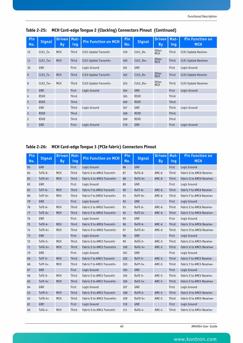
Functional Description
12 CLK1_Tx- MCH Third CLK1 Update Transmit- 159 CLK1_Rx- Other MCH Third CLK1 Update Receive-
11 CLK1_Tx+ MCH Third CLK1 Update Transmit+ 160 CLK1_Rx+ Other MCH Third CLK1 Update Receive+
10 GND First Logic-Ground 161 GND First Logic-Ground
9 CLK3_Tx- MCH Third CLK3 Update Transmit- 162 CLK3_Rx- Other MCH Third CLK3 Update Receive-
8 CLK3_Tx+ MCH Third CLK3 Update Transmit+ 163 CLK3_Rx+ Other MCH Third CLK3 Update Receive+
7 GND First Logic-Ground 164 GND First Logic-Ground
6 RSVD Third 165 RSVD Third
5 RSVD Third 166 RSVD Third
4 GND Third Logic-Ground 167 GND Third Logic-Ground
3 RSVD Third 168 RSVD Third
2 RSVD Third 169 RSVD Third
1 GND First Logic-Ground 170 GND First Logic-Ground
Table 2-26: MCH Card-edge Tongue 3 (PCIe fabric) Connectors Pinout
Pin No.
SignalDriven
ByMat-ing
Pin Function on MCHPin No.
SignalDriven
ByMat-ing
Pin Function on MCH
85 GND First Logic Ground 86 GND First Logic Ground
84 TxFG-6- MCH Third Fabric G to AMC6 Transmit- 87 RxFG-6- AMC-6 Third Fabric G to AMC6 Receive-
83 TxFG-6+ MCH Third Fabric G to AMC6 Transmit+ 88 RxFG-6+ AMC-6 Third Fabric G to AMC6 Receive+
82 GND First Logic Ground 89 GND First Logic Ground
81 TxFF-6- MCH Third Fabric F to AMC6 Transmit- 90 RxFF-6- AMC-6 Third Fabric F to AMC6 Receive-
80 TxFF-6+ MCH Third Fabric F to AMC6 Transmit+ 91 RxFF-6+ AMC-6 Third Fabric F to AMC6 Receive+
79 GND First Logic Ground 92 GND First Logic Ground
78 TxFE-6- MCH Third Fabric E to AMC6 Transmit- 93 RxFE-6- AMC-6 Third Fabric E to AMC6 Receive-
77 TxFE-6+ MCH Third Fabric E to AMC6 Transmit+ 94 RxFE-6+ AMC-6 Third Fabric E to AMC6 Receive+
76 GND First Logic Ground 95 GND First Logic Ground
75 TxFD-6- MCH Third Fabric D to AMC6 Transmit- 96 RxFD-6- AMC-6 Third Fabric D to AMC6 Receive-
74 TxFD-6+ MCH Third Fabric D to AMC6 Transmit+ 97 RxFD-6+ AMC-6 Third Fabric D to AMC6 Receive+
73 GND First Logic Ground 98 GND First Logic Ground
72 TxFG-5- MCH Third Fabric G to AMC5 Transmit- 99 RxFG-5- AMC-5 Third Fabric G to AMC5 Receive-
71 TxFG-5+ MCH Third Fabric G to AMC5 Transmit+ 100 RxFG-5+ AMC-5 Third Fabric G to AMC5 Receive+
70 GND First Logic Ground 101 GND First Logic Ground
69 TxFF-5- MCH Third Fabric F to AMC5 Transmit- 102 RxFF-5- AMC-5 Third Fabric F to AMC5 Receive-
68 TxFF-5+ MCH Third Fabric F to AMC5 Transmit+ 103 RxFF-5+ AMC-5 Third Fabric F to AMC5 Receive+
67 GND First Logic Ground 104 GND First Logic Ground
66 TxFE-5- MCH Third Fabric E to AMC5 Transmit- 105 RxFE-5- AMC-5 Third Fabric E to AMC5 Receive-
65 TxFE-5+ MCH Third Fabric E to AMC5 Transmit+ 106 RxFE-5+ AMC-5 Third Fabric E to AMC5 Receive+
64 GND First Logic Ground 107 GND First Logic Ground
63 TxFD-5- MCH Third Fabric D to AMC5 Transmit- 108 RxFD-5- AMC-5 Third Fabric D to AMC5 Receive-
62 TxFD-5+ MCH Third Fabric D to AMC5 Transmit+ 109 RxFD-5+ AMC-5 Third Fabric D to AMC5 Receive+
61 GND First Logic Ground 110 GND First Logic Ground
60 TxFG-4- MCH Third Fabric G to AMC4 Transmit- 111 RxFG-4- AMC-4 Third Fabric G to AMC4 Receive-
Table 2-25: MCH Card-edge Tongue 2 (Clocking) Connectors Pinout (Continued)
Pin No.
SignalDriven
ByMat-ing
Pin Function on MCHPin No.
SignalDriven
ByMat-ing
Pin Function on MCH
40 AM4904 User Guide
www.kontron.com
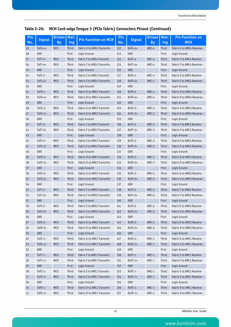
Functional Description
59 TxFG-4+ MCH Third Fabric G to AMC4 Transmit+ 112 RxFG-4+ AMC-4 Third Fabric G to AMC4 Receive+
58 GND First Logic Ground 113 GND First Logic Ground
57 TxFF-4- MCH Third Fabric F to AMC4 Transmit- 114 RxFF-4- AMC-4 Third Fabric F to AMC4 Receive-
56 TxFF-4+ MCH Third Fabric F to AMC4 Transmit+ 115 RxFF-4+ AMC-4 Third Fabric F to AMC4 Receive+
55 GND First Logic Ground 116 GND First Logic Ground
54 TxFE-4- MCH Third Fabric E to AMC4 Transmit- 117 RxFE-4- AMC-4 Third Fabric E to AMC4 Receive-
53 TxFE-4+ MCH Third Fabric E to AMC4 Transmit+ 118 RxFE-4+ AMC-4 Third Fabric E to AMC4 Receive+
52 GND First Logic Ground 119 GND First Logic Ground
51 TxFD-4 MCH Third Fabric D to AMC4 Transmit- 120 RxFD-4 AMC-4 Third Fabric D to AMC4 Receive-
50 TxFD-4+ MCH Third Fabric D to AMC4 Transmit+ 121 RxFD-4+ AMC-4 Third Fabric D to AMC4 Receive+
49 GND First Logic Ground 122 GND First Logic Ground
48 TxFG-3- MCH Third Fabric G to AMC3 Transmit- 123 RxFG-3- AMC-3 Third Fabric G to AMC3 Receive-
47 TxFG-3+ MCH Third Fabric G to AMC3 Transmit+ 124 RxFG-3+ AMC-3 Third Fabric G to AMC3 Receive+
46 GND First Logic Ground 125 GND First Logic Ground
45 TxFF-3- MCH Third Fabric F to AMC3 Transmit- 126 RxFF-3- AMC-3 Third Fabric F to AMC3 Receive-
44 TxFF-3+ MCH Third Fabric F to AMC3 Transmit+ 127 RxFF-3+ AMC-3 Third Fabric F to AMC3 Receive+
43 GND First Logic Ground 128 GND First Logic Ground
42 TxFE-3- MCH Third Fabric E to AMC3 Transmit- 129 RxFE-3- AMC-3 Third Fabric E to AMC3 Receive-
41 TxFE-3+ MCH Third Fabric E to AMC3 Transmit+ 130 RxFE-3+ AMC-3 Third Fabric E to AMC3 Receive+
40 GND First Logic Ground 131 GND First Logic Ground
39 TxFD-3- MCH Third Fabric D to AMC3 Transmit- 132 RxFD-3- AMC-3 Third Fabric D to AMC3 Receive-
38 TxFD-3+ MCH Third Fabric D to AMC3 Transmit+ 133 RxFD-3+ AMC-3 Third Fabric D to AMC3 Receive+
37 GND First Logic Ground 134 GND First Logic Ground
36 TxFG-2- MCH Third Fabric G to AMC2 Transmit- 135 RxFG-2- AMC-2 Third Fabric G to AMC2 Receive-
35 TxFG-2+ MCH Third Fabric G to AMC2 Transmit+ 136 RxFG-2+ AMC-2 Third Fabric G to AMC2 Receive+
34 GND First Logic Ground 137 GND First Logic Ground
33 TxFF-2- MCH Third Fabric F to AMC2 Transmit- 138 RxFF-2- AMC-2 Third Fabric F to AMC2 Receive-
32 TxFF-2+ MCH Third Fabric F to AMC2 Transmit+ 139 RxFF-2+ AMC-2 Third Fabric F to AMC2 Receive+
31 GND First Logic Ground 140 GND First Logic Ground
30 TxFE-2- MCH Third Fabric E to AMC2 Transmit- 141 RxFE-2- AMC-2 Third Fabric E to AMC2 Receive-
29 TxFE-2+ MCH Third Fabric E to AMC2 Transmit+ 142 RxFE-2+ AMC-2 Third Fabric E to AMC2 Receive+
28 GND First Logic Ground 143 GND First Logic Ground
27 TxFD-2- MCH Third Fabric D to AMC2 Transmit- 144 RxFD-2- AMC-2 Third Fabric D to AMC2 Receive-
26 TxFD-2+ MCH Third Fabric D to AMC2 Transmit+ 145 RxFD-2+ AMC-2 Third Fabric D to AMC2 Receive+
25 GND First Logic Ground 146 GND First Logic Ground
24 TxFG-1- MCH Third Fabric G to AMC1 Transmit- 147 RxFG-1- AMC-1 Third Fabric G to AMC1 Receive-
23 TxFG-1+ MCH Third Fabric G to AMC1 Transmit+ 148 RxFG-1+ AMC-1 Third Fabric G to AMC1 Receive+
22 GND First Logic Ground 149 GND First Logic Ground
21 TxFF-1- MCH Third Fabric F to AMC1 Transmit- 150 RxFF-1- AMC-1 Third Fabric F to AMC1 Receive-
20 TxFF-1+ MCH Third Fabric F to AMC1 Transmit+ 151 RxFF-1+ AMC-1 Third Fabric F to AMC1 Receive+
19 GND First Logic Ground 152 GND First Logic Ground
18 TxFE-1- MCH Third Fabric E to AMC1 Transmit- 153 RxFE-1- AMC-1 Third Fabric E to AMC1 Receive-
17 TxFE-1+ MCH Third Fabric E to AMC1 Transmit+ 154 RxFE-1+ AMC-1 Third Fabric E to AMC1 Receive+
16 GND First Logic Ground 155 GND First Logic Ground
15 TxFD-1- MCH Third Fabric D to AMC1 Transmit- 156 RxFD-1- AMC-1 Third Fabric D to AMC1 Receive-
14 TxFD-1+ MCH Third Fabric D to AMC1 Transmit+ 157 RxFD-1+ AMC-1 Third Fabric D to AMC1 Receive+
Table 2-26: MCH Card-edge Tongue 3 (PCIe fabric) Connectors Pinout (Continued)
Pin No.
SignalDriven
ByMat-ing
Pin Function on MCHPin No.
SignalDriven
ByMat-ing
Pin Function on MCH
41 AM4904 User Guide
www.kontron.com
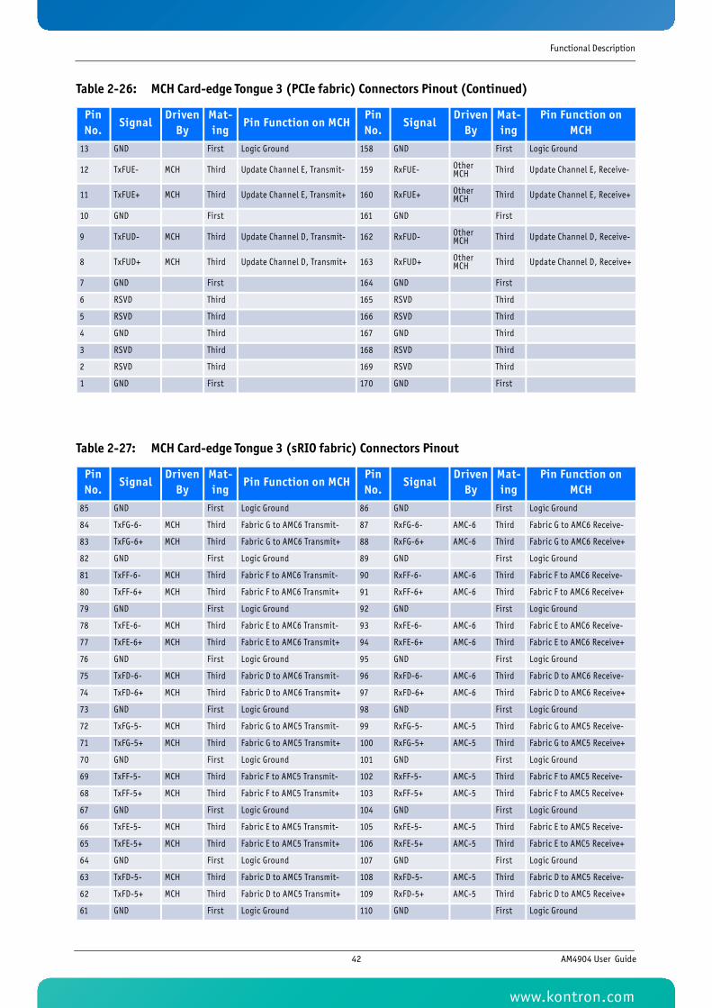
Functional Description
13 GND First Logic Ground 158 GND First Logic Ground
12 TxFUE- MCH Third Update Channel E, Transmit- 159 RxFUE- Other MCH Third Update Channel E, Receive-
11 TxFUE+ MCH Third Update Channel E, Transmit+ 160 RxFUE+ Other MCH Third Update Channel E, Receive+
10 GND First 161 GND First
9 TxFUD- MCH Third Update Channel D, Transmit- 162 RxFUD- Other MCH Third Update Channel D, Receive-
8 TxFUD+ MCH Third Update Channel D, Transmit+ 163 RxFUD+ Other MCH Third Update Channel D, Receive+
7 GND First 164 GND First
6 RSVD Third 165 RSVD Third
5 RSVD Third 166 RSVD Third
4 GND Third 167 GND Third
3 RSVD Third 168 RSVD Third
2 RSVD Third 169 RSVD Third
1 GND First 170 GND First
Table 2-27: MCH Card-edge Tongue 3 (sRIO fabric) Connectors Pinout
Pin No.
SignalDriven
ByMat-ing
Pin Function on MCHPin No.
SignalDriven
ByMat-ing
Pin Function on MCH
85 GND First Logic Ground 86 GND First Logic Ground
84 TxFG-6- MCH Third Fabric G to AMC6 Transmit- 87 RxFG-6- AMC-6 Third Fabric G to AMC6 Receive-
83 TxFG-6+ MCH Third Fabric G to AMC6 Transmit+ 88 RxFG-6+ AMC-6 Third Fabric G to AMC6 Receive+
82 GND First Logic Ground 89 GND First Logic Ground
81 TxFF-6- MCH Third Fabric F to AMC6 Transmit- 90 RxFF-6- AMC-6 Third Fabric F to AMC6 Receive-
80 TxFF-6+ MCH Third Fabric F to AMC6 Transmit+ 91 RxFF-6+ AMC-6 Third Fabric F to AMC6 Receive+
79 GND First Logic Ground 92 GND First Logic Ground
78 TxFE-6- MCH Third Fabric E to AMC6 Transmit- 93 RxFE-6- AMC-6 Third Fabric E to AMC6 Receive-
77 TxFE-6+ MCH Third Fabric E to AMC6 Transmit+ 94 RxFE-6+ AMC-6 Third Fabric E to AMC6 Receive+
76 GND First Logic Ground 95 GND First Logic Ground
75 TxFD-6- MCH Third Fabric D to AMC6 Transmit- 96 RxFD-6- AMC-6 Third Fabric D to AMC6 Receive-
74 TxFD-6+ MCH Third Fabric D to AMC6 Transmit+ 97 RxFD-6+ AMC-6 Third Fabric D to AMC6 Receive+
73 GND First Logic Ground 98 GND First Logic Ground
72 TxFG-5- MCH Third Fabric G to AMC5 Transmit- 99 RxFG-5- AMC-5 Third Fabric G to AMC5 Receive-
71 TxFG-5+ MCH Third Fabric G to AMC5 Transmit+ 100 RxFG-5+ AMC-5 Third Fabric G to AMC5 Receive+
70 GND First Logic Ground 101 GND First Logic Ground
69 TxFF-5- MCH Third Fabric F to AMC5 Transmit- 102 RxFF-5- AMC-5 Third Fabric F to AMC5 Receive-
68 TxFF-5+ MCH Third Fabric F to AMC5 Transmit+ 103 RxFF-5+ AMC-5 Third Fabric F to AMC5 Receive+
67 GND First Logic Ground 104 GND First Logic Ground
66 TxFE-5- MCH Third Fabric E to AMC5 Transmit- 105 RxFE-5- AMC-5 Third Fabric E to AMC5 Receive-
65 TxFE-5+ MCH Third Fabric E to AMC5 Transmit+ 106 RxFE-5+ AMC-5 Third Fabric E to AMC5 Receive+
64 GND First Logic Ground 107 GND First Logic Ground
63 TxFD-5- MCH Third Fabric D to AMC5 Transmit- 108 RxFD-5- AMC-5 Third Fabric D to AMC5 Receive-
62 TxFD-5+ MCH Third Fabric D to AMC5 Transmit+ 109 RxFD-5+ AMC-5 Third Fabric D to AMC5 Receive+
61 GND First Logic Ground 110 GND First Logic Ground
Table 2-26: MCH Card-edge Tongue 3 (PCIe fabric) Connectors Pinout (Continued)
Pin No.
SignalDriven
ByMat-ing
Pin Function on MCHPin No.
SignalDriven
ByMat-ing
Pin Function on MCH
42 AM4904 User Guide
www.kontron.com
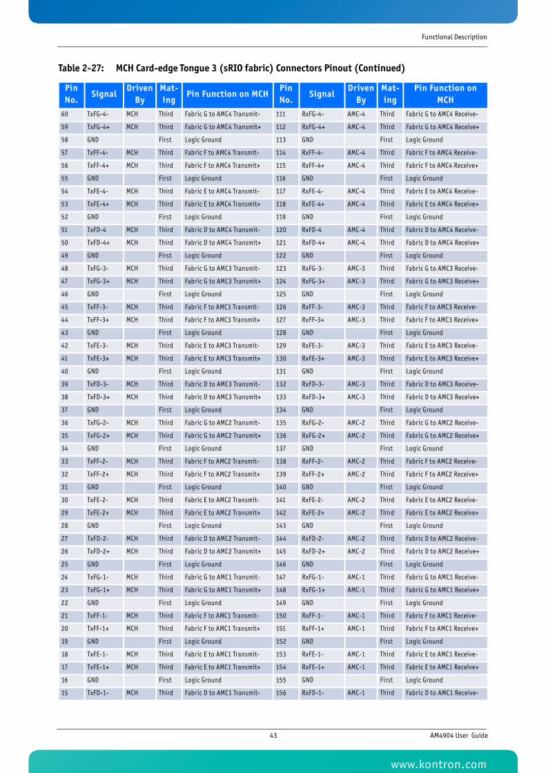
Functional Description
60 TxFG-4- MCH Third Fabric G to AMC4 Transmit- 111 RxFG-4- AMC-4 Third Fabric G to AMC4 Receive-
59 TxFG-4+ MCH Third Fabric G to AMC4 Transmit+ 112 RxFG-4+ AMC-4 Third Fabric G to AMC4 Receive+
58 GND First Logic Ground 113 GND First Logic Ground
57 TxFF-4- MCH Third Fabric F to AMC4 Transmit- 114 RxFF-4- AMC-4 Third Fabric F to AMC4 Receive-
56 TxFF-4+ MCH Third Fabric F to AMC4 Transmit+ 115 RxFF-4+ AMC-4 Third Fabric F to AMC4 Receive+
55 GND First Logic Ground 116 GND First Logic Ground
54 TxFE-4- MCH Third Fabric E to AMC4 Transmit- 117 RxFE-4- AMC-4 Third Fabric E to AMC4 Receive-
53 TxFE-4+ MCH Third Fabric E to AMC4 Transmit+ 118 RxFE-4+ AMC-4 Third Fabric E to AMC4 Receive+
52 GND First Logic Ground 119 GND First Logic Ground
51 TxFD-4 MCH Third Fabric D to AMC4 Transmit- 120 RxFD-4 AMC-4 Third Fabric D to AMC4 Receive-
50 TxFD-4+ MCH Third Fabric D to AMC4 Transmit+ 121 RxFD-4+ AMC-4 Third Fabric D to AMC4 Receive+
49 GND First Logic Ground 122 GND First Logic Ground
48 TxFG-3- MCH Third Fabric G to AMC3 Transmit- 123 RxFG-3- AMC-3 Third Fabric G to AMC3 Receive-
47 TxFG-3+ MCH Third Fabric G to AMC3 Transmit+ 124 RxFG-3+ AMC-3 Third Fabric G to AMC3 Receive+
46 GND First Logic Ground 125 GND First Logic Ground
45 TxFF-3- MCH Third Fabric F to AMC3 Transmit- 126 RxFF-3- AMC-3 Third Fabric F to AMC3 Receive-
44 TxFF-3+ MCH Third Fabric F to AMC3 Transmit+ 127 RxFF-3+ AMC-3 Third Fabric F to AMC3 Receive+
43 GND First Logic Ground 128 GND First Logic Ground
42 TxFE-3- MCH Third Fabric E to AMC3 Transmit- 129 RxFE-3- AMC-3 Third Fabric E to AMC3 Receive-
41 TxFE-3+ MCH Third Fabric E to AMC3 Transmit+ 130 RxFE-3+ AMC-3 Third Fabric E to AMC3 Receive+
40 GND First Logic Ground 131 GND First Logic Ground
39 TxFD-3- MCH Third Fabric D to AMC3 Transmit- 132 RxFD-3- AMC-3 Third Fabric D to AMC3 Receive-
38 TxFD-3+ MCH Third Fabric D to AMC3 Transmit+ 133 RxFD-3+ AMC-3 Third Fabric D to AMC3 Receive+
37 GND First Logic Ground 134 GND First Logic Ground
36 TxFG-2- MCH Third Fabric G to AMC2 Transmit- 135 RxFG-2- AMC-2 Third Fabric G to AMC2 Receive-
35 TxFG-2+ MCH Third Fabric G to AMC2 Transmit+ 136 RxFG-2+ AMC-2 Third Fabric G to AMC2 Receive+
34 GND First Logic Ground 137 GND First Logic Ground
33 TxFF-2- MCH Third Fabric F to AMC2 Transmit- 138 RxFF-2- AMC-2 Third Fabric F to AMC2 Receive-
32 TxFF-2+ MCH Third Fabric F to AMC2 Transmit+ 139 RxFF-2+ AMC-2 Third Fabric F to AMC2 Receive+
31 GND First Logic Ground 140 GND First Logic Ground
30 TxFE-2- MCH Third Fabric E to AMC2 Transmit- 141 RxFE-2- AMC-2 Third Fabric E to AMC2 Receive-
29 TxFE-2+ MCH Third Fabric E to AMC2 Transmit+ 142 RxFE-2+ AMC-2 Third Fabric E to AMC2 Receive+
28 GND First Logic Ground 143 GND First Logic Ground
27 TxFD-2- MCH Third Fabric D to AMC2 Transmit- 144 RxFD-2- AMC-2 Third Fabric D to AMC2 Receive-
26 TxFD-2+ MCH Third Fabric D to AMC2 Transmit+ 145 RxFD-2+ AMC-2 Third Fabric D to AMC2 Receive+
25 GND First Logic Ground 146 GND First Logic Ground
24 TxFG-1- MCH Third Fabric G to AMC1 Transmit- 147 RxFG-1- AMC-1 Third Fabric G to AMC1 Receive-
23 TxFG-1+ MCH Third Fabric G to AMC1 Transmit+ 148 RxFG-1+ AMC-1 Third Fabric G to AMC1 Receive+
22 GND First Logic Ground 149 GND First Logic Ground
21 TxFF-1- MCH Third Fabric F to AMC1 Transmit- 150 RxFF-1- AMC-1 Third Fabric F to AMC1 Receive-
20 TxFF-1+ MCH Third Fabric F to AMC1 Transmit+ 151 RxFF-1+ AMC-1 Third Fabric F to AMC1 Receive+
19 GND First Logic Ground 152 GND First Logic Ground
18 TxFE-1- MCH Third Fabric E to AMC1 Transmit- 153 RxFE-1- AMC-1 Third Fabric E to AMC1 Receive-
17 TxFE-1+ MCH Third Fabric E to AMC1 Transmit+ 154 RxFE-1+ AMC-1 Third Fabric E to AMC1 Receive+
16 GND First Logic Ground 155 GND First Logic Ground
15 TxFD-1- MCH Third Fabric D to AMC1 Transmit- 156 RxFD-1- AMC-1 Third Fabric D to AMC1 Receive-
Table 2-27: MCH Card-edge Tongue 3 (sRIO fabric) Connectors Pinout (Continued)
Pin No.
SignalDriven
ByMat-ing
Pin Function on MCHPin No.
SignalDriven
ByMat-ing
Pin Function on MCH
43 AM4904 User Guide
www.kontron.com
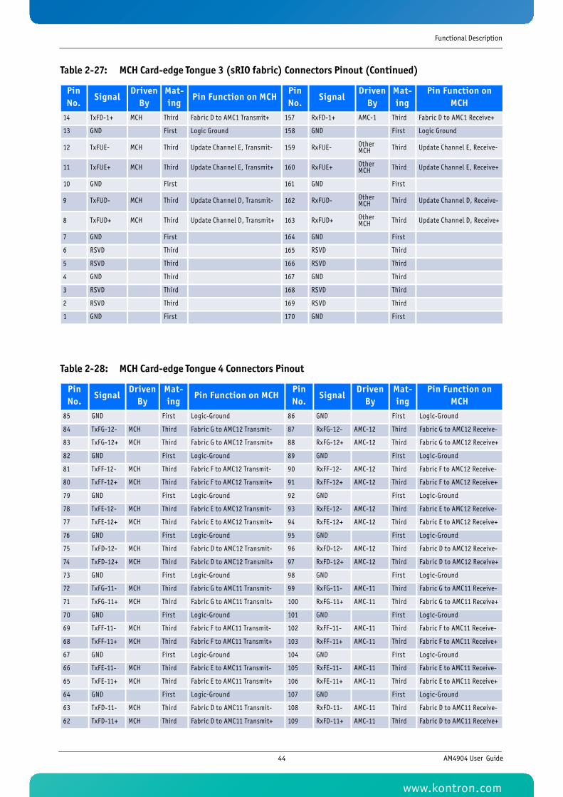
Functional Description
14 TxFD-1+ MCH Third Fabric D to AMC1 Transmit+ 157 RxFD-1+ AMC-1 Third Fabric D to AMC1 Receive+
13 GND First Logic Ground 158 GND First Logic Ground
12 TxFUE- MCH Third Update Channel E, Transmit- 159 RxFUE- Other MCH Third Update Channel E, Receive-
11 TxFUE+ MCH Third Update Channel E, Transmit+ 160 RxFUE+ Other MCH Third Update Channel E, Receive+
10 GND First 161 GND First
9 TxFUD- MCH Third Update Channel D, Transmit- 162 RxFUD- Other MCH Third Update Channel D, Receive-
8 TxFUD+ MCH Third Update Channel D, Transmit+ 163 RxFUD+ Other MCH Third Update Channel D, Receive+
7 GND First 164 GND First
6 RSVD Third 165 RSVD Third
5 RSVD Third 166 RSVD Third
4 GND Third 167 GND Third
3 RSVD Third 168 RSVD Third
2 RSVD Third 169 RSVD Third
1 GND First 170 GND First
Table 2-28: MCH Card-edge Tongue 4 Connectors Pinout
Pin No.
SignalDriven
ByMat-ing
Pin Function on MCHPin No.
SignalDriven
ByMat-ing
Pin Function on MCH
85 GND First Logic-Ground 86 GND First Logic-Ground
84 TxFG-12- MCH Third Fabric G to AMC12 Transmit- 87 RxFG-12- AMC-12 Third Fabric G to AMC12 Receive-
83 TxFG-12+ MCH Third Fabric G to AMC12 Transmit+ 88 RxFG-12+ AMC-12 Third Fabric G to AMC12 Receive+
82 GND First Logic-Ground 89 GND First Logic-Ground
81 TxFF-12- MCH Third Fabric F to AMC12 Transmit- 90 RxFF-12- AMC-12 Third Fabric F to AMC12 Receive-
80 TxFF-12+ MCH Third Fabric F to AMC12 Transmit+ 91 RxFF-12+ AMC-12 Third Fabric F to AMC12 Receive+
79 GND First Logic-Ground 92 GND First Logic-Ground
78 TxFE-12- MCH Third Fabric E to AMC12 Transmit- 93 RxFE-12- AMC-12 Third Fabric E to AMC12 Receive-
77 TxFE-12+ MCH Third Fabric E to AMC12 Transmit+ 94 RxFE-12+ AMC-12 Third Fabric E to AMC12 Receive+
76 GND First Logic-Ground 95 GND First Logic-Ground
75 TxFD-12- MCH Third Fabric D to AMC12 Transmit- 96 RxFD-12- AMC-12 Third Fabric D to AMC12 Receive-
74 TxFD-12+ MCH Third Fabric D to AMC12 Transmit+ 97 RxFD-12+ AMC-12 Third Fabric D to AMC12 Receive+
73 GND First Logic-Ground 98 GND First Logic-Ground
72 TxFG-11- MCH Third Fabric G to AMC11 Transmit- 99 RxFG-11- AMC-11 Third Fabric G to AMC11 Receive-
71 TxFG-11+ MCH Third Fabric G to AMC11 Transmit+ 100 RxFG-11+ AMC-11 Third Fabric G to AMC11 Receive+
70 GND First Logic-Ground 101 GND First Logic-Ground
69 TxFF-11- MCH Third Fabric F to AMC11 Transmit- 102 RxFF-11- AMC-11 Third Fabric F to AMC11 Receive-
68 TxFF-11+ MCH Third Fabric F to AMC11 Transmit+ 103 RxFF-11+ AMC-11 Third Fabric F to AMC11 Receive+
67 GND First Logic-Ground 104 GND First Logic-Ground
66 TxFE-11- MCH Third Fabric E to AMC11 Transmit- 105 RxFE-11- AMC-11 Third Fabric E to AMC11 Receive-
65 TxFE-11+ MCH Third Fabric E to AMC11 Transmit+ 106 RxFE-11+ AMC-11 Third Fabric E to AMC11 Receive+
64 GND First Logic-Ground 107 GND First Logic-Ground
63 TxFD-11- MCH Third Fabric D to AMC11 Transmit- 108 RxFD-11- AMC-11 Third Fabric D to AMC11 Receive-
62 TxFD-11+ MCH Third Fabric D to AMC11 Transmit+ 109 RxFD-11+ AMC-11 Third Fabric D to AMC11 Receive+
Table 2-27: MCH Card-edge Tongue 3 (sRIO fabric) Connectors Pinout (Continued)
Pin No.
SignalDriven
ByMat-ing
Pin Function on MCHPin No.
SignalDriven
ByMat-ing
Pin Function on MCH
44 AM4904 User Guide
www.kontron.com
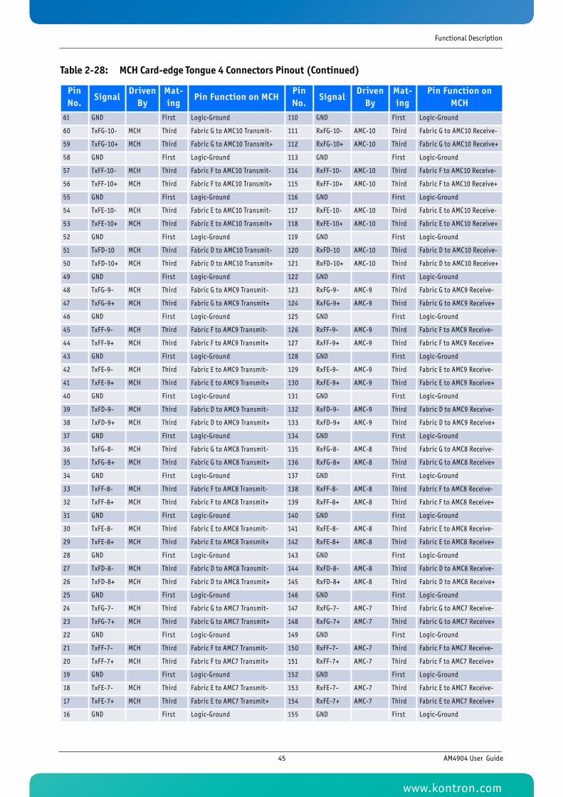
Functional Description
Pin No.
SignalDriven
ByMat-ing
Pin Function on MCHPin No.
SignalDriven
ByMat-ing
Pin Function on MCH
61 GND First Logic-Ground 110 GND First Logic-Ground
60 TxFG-10- MCH Third Fabric G to AMC10 Transmit- 111 RxFG-10- AMC-10 Third Fabric G to AMC10 Receive-
59 TxFG-10+ MCH Third Fabric G to AMC10 Transmit+ 112 RxFG-10+ AMC-10 Third Fabric G to AMC10 Receive+
58 GND First Logic-Ground 113 GND First Logic-Ground
57 TxFF-10- MCH Third Fabric F to AMC10 Transmit- 114 RxFF-10- AMC-10 Third Fabric F to AMC10 Receive-
56 TxFF-10+ MCH Third Fabric F to AMC10 Transmit+ 115 RxFF-10+ AMC-10 Third Fabric F to AMC10 Receive+
55 GND First Logic-Ground 116 GND First Logic-Ground
54 TxFE-10- MCH Third Fabric E to AMC10 Transmit- 117 RxFE-10- AMC-10 Third Fabric E to AMC10 Receive-
53 TxFE-10+ MCH Third Fabric E to AMC10 Transmit+ 118 RxFE-10+ AMC-10 Third Fabric E to AMC10 Receive+
52 GND First Logic-Ground 119 GND First Logic-Ground
51 TxFD-10 MCH Third Fabric D to AMC10 Transmit- 120 RxFD-10 AMC-10 Third Fabric D to AMC10 Receive-
50 TxFD-10+ MCH Third Fabric D to AMC10 Transmit+ 121 RxFD-10+ AMC-10 Third Fabric D to AMC10 Receive+
49 GND First Logic-Ground 122 GND First Logic-Ground
48 TxFG-9- MCH Third Fabric G to AMC9 Transmit- 123 RxFG-9- AMC-9 Third Fabric G to AMC9 Receive-
47 TxFG-9+ MCH Third Fabric G to AMC9 Transmit+ 124 RxFG-9+ AMC-9 Third Fabric G to AMC9 Receive+
46 GND First Logic-Ground 125 GND First Logic-Ground
45 TxFF-9- MCH Third Fabric F to AMC9 Transmit- 126 RxFF-9- AMC-9 Third Fabric F to AMC9 Receive-
44 TxFF-9+ MCH Third Fabric F to AMC9 Transmit+ 127 RxFF-9+ AMC-9 Third Fabric F to AMC9 Receive+
43 GND First Logic-Ground 128 GND First Logic-Ground
42 TxFE-9- MCH Third Fabric E to AMC9 Transmit- 129 RxFE-9- AMC-9 Third Fabric E to AMC9 Receive-
41 TxFE-9+ MCH Third Fabric E to AMC9 Transmit+ 130 RxFE-9+ AMC-9 Third Fabric E to AMC9 Receive+
40 GND First Logic-Ground 131 GND First Logic-Ground
39 TxFD-9- MCH Third Fabric D to AMC9 Transmit- 132 RxFD-9- AMC-9 Third Fabric D to AMC9 Receive-
38 TxFD-9+ MCH Third Fabric D to AMC9 Transmit+ 133 RxFD-9+ AMC-9 Third Fabric D to AMC9 Receive+
37 GND First Logic-Ground 134 GND First Logic-Ground
36 TxFG-8- MCH Third Fabric G to AMC8 Transmit- 135 RxFG-8- AMC-8 Third Fabric G to AMC8 Receive-
35 TxFG-8+ MCH Third Fabric G to AMC8 Transmit+ 136 RxFG-8+ AMC-8 Third Fabric G to AMC8 Receive+
34 GND First Logic-Ground 137 GND First Logic-Ground
33 TxFF-8- MCH Third Fabric F to AMC8 Transmit- 138 RxFF-8- AMC-8 Third Fabric F to AMC8 Receive-
32 TxFF-8+ MCH Third Fabric F to AMC8 Transmit+ 139 RxFF-8+ AMC-8 Third Fabric F to AMC8 Receive+
31 GND First Logic-Ground 140 GND First Logic-Ground
30 TxFE-8- MCH Third Fabric E to AMC8 Transmit- 141 RxFE-8- AMC-8 Third Fabric E to AMC8 Receive-
29 TxFE-8+ MCH Third Fabric E to AMC8 Transmit+ 142 RxFE-8+ AMC-8 Third Fabric E to AMC8 Receive+
28 GND First Logic-Ground 143 GND First Logic-Ground
27 TxFD-8- MCH Third Fabric D to AMC8 Transmit- 144 RxFD-8- AMC-8 Third Fabric D to AMC8 Receive-
26 TxFD-8+ MCH Third Fabric D to AMC8 Transmit+ 145 RxFD-8+ AMC-8 Third Fabric D to AMC8 Receive+
25 GND First Logic-Ground 146 GND First Logic-Ground
24 TxFG-7- MCH Third Fabric G to AMC7 Transmit- 147 RxFG-7- AMC-7 Third Fabric G to AMC7 Receive-
23 TxFG-7+ MCH Third Fabric G to AMC7 Transmit+ 148 RxFG-7+ AMC-7 Third Fabric G to AMC7 Receive+
22 GND First Logic-Ground 149 GND First Logic-Ground
21 TxFF-7- MCH Third Fabric F to AMC7 Transmit- 150 RxFF-7- AMC-7 Third Fabric F to AMC7 Receive-
20 TxFF-7+ MCH Third Fabric F to AMC7 Transmit+ 151 RxFF-7+ AMC-7 Third Fabric F to AMC7 Receive+
19 GND First Logic-Ground 152 GND First Logic-Ground
18 TxFE-7- MCH Third Fabric E to AMC7 Transmit- 153 RxFE-7- AMC-7 Third Fabric E to AMC7 Receive-
17 TxFE-7+ MCH Third Fabric E to AMC7 Transmit+ 154 RxFE-7+ AMC-7 Third Fabric E to AMC7 Receive+
16 GND First Logic-Ground 155 GND First Logic-Ground
Table 2-28: MCH Card-edge Tongue 4 Connectors Pinout (Continued)
45 AM4904 User Guide
www.kontron.com
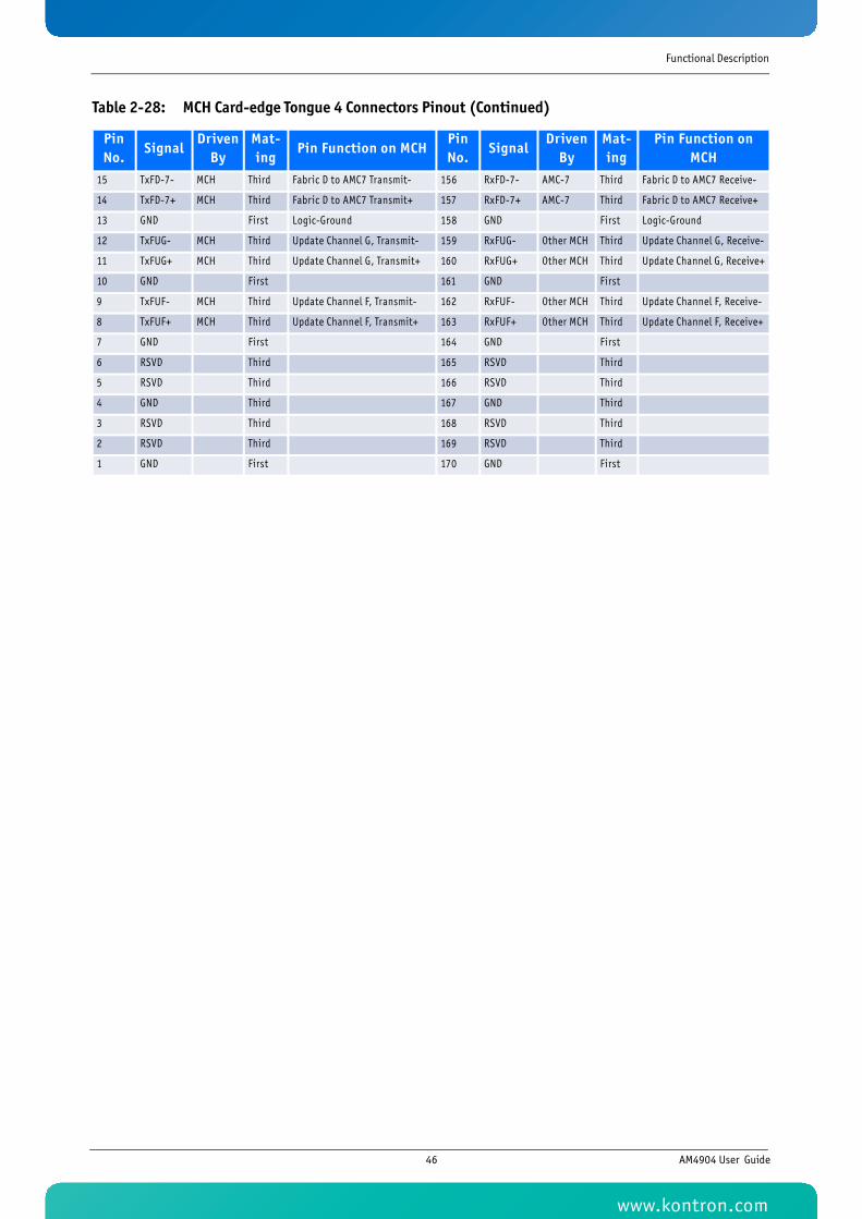
Functional Description
Pin No.
SignalDriven
ByMat-ing
Pin Function on MCHPin No.
SignalDriven
ByMat-ing
Pin Function on MCH
15 TxFD-7- MCH Third Fabric D to AMC7 Transmit- 156 RxFD-7- AMC-7 Third Fabric D to AMC7 Receive-
14 TxFD-7+ MCH Third Fabric D to AMC7 Transmit+ 157 RxFD-7+ AMC-7 Third Fabric D to AMC7 Receive+
13 GND First Logic-Ground 158 GND First Logic-Ground
12 TxFUG- MCH Third Update Channel G, Transmit- 159 RxFUG- Other MCH Third Update Channel G, Receive-
11 TxFUG+ MCH Third Update Channel G, Transmit+ 160 RxFUG+ Other MCH Third Update Channel G, Receive+
10 GND First 161 GND First
9 TxFUF- MCH Third Update Channel F, Transmit- 162 RxFUF- Other MCH Third Update Channel F, Receive-
8 TxFUF+ MCH Third Update Channel F, Transmit+ 163 RxFUF+ Other MCH Third Update Channel F, Receive+
7 GND First 164 GND First
6 RSVD Third 165 RSVD Third
5 RSVD Third 166 RSVD Third
4 GND Third 167 GND Third
3 RSVD Third 168 RSVD Third
2 RSVD Third 169 RSVD Third
1 GND First 170 GND First
Table 2-28: MCH Card-edge Tongue 4 Connectors Pinout (Continued)
46 AM4904 User Guide
www.kontron.com

47KTC5520/EATX
Chapter 3
Operating the Unit
www.kontron.com
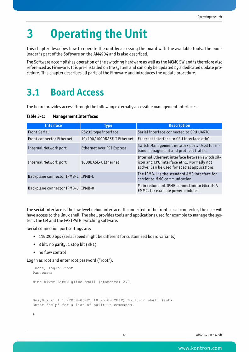
Operating the Unit
3 Operating the UnitThis chapter describes how to operate the unit by accessing the board with the available tools. The boot-loader is part of the Software on the AM4904 and is also described.
The Software accomplishes operation of the switching hardware as well as the MCMC SW and is therefore alsoreferenced as Firmware. It is pre-installed on the system and can only be updated by a dedicated update pro-cedure. This chapter describes all parts of the Firmware and introduces the update procedure.
3.1 Board AccessThe board provides access through the following externally accessible management interfaces.
The serial Interface is the low level debug interface. If connected to the front serial connector, the user willhave access to the linux shell. The shell provides tools and applications used for example to manage the sys-tem, the CM and the FASTPATH switching software.
Serial connection port settings are:
• 115,200 bps (serial speed might be different for customized board variants)
• 8 bit, no parity, 1 stop bit (8N1)
• no flow control
Log in as root and enter root password (“root”).
(none) login: rootPassword:
Wind River Linux glibc_small (standard) 2.0
BusyBox v1.4.1 (2009-06-25 18:25:09 CEST) Built-in shell (ash)Enter 'help' for a list of built-in commands.
#
Table 3-1: Management Interfaces
Interface Type Description
Front Serial RS232 type interface Serial interface connected to CPU UART0
Front connector Ethernet 10/100/1000BASE-T Ethernet Ethernet interface to CPU interface eth0
Internal Network port Ethernet over PCI ExpressSwitch Management network port. Used for in-band management and protocol traff ic.
Internal Network port 1000BASE-X EthernetInternal Ethernet interface between switch sil-icon and CPU interface eth1. Normally not active. Can be used for special applications
Backplane connector IPMB-L IPMB-LThe IPMB-L is the standard AMC interface for carrier to MMC communication.
Backplane connector IPMB-0 IPMB-0Main redundant IPMB connection to MicroTCA EMMC, for example power modules.
48 AM4904 User Guide
www.kontron.com
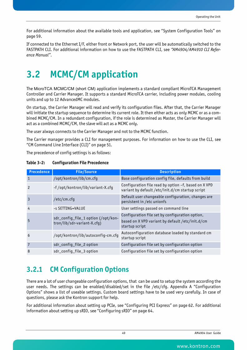
Operating the Unit
For additional information about the available tools and application, see “System Configuration Tools” onpage 59.
If connected to the Ethernet I/F, either front or Network port, the user will be automatically switched to theFASTPATH CLI. For additional information on how to use the FASTPATH CLI, see “AM4904/AM4910 CLI Refer-ence Manual”.
3.2 MCMC/CM applicationThe MicroTCA MCMC/CM (short CM) application implements a standard compliant MicroTCA ManagementController and Carrier Manager. It supports a standard MicroTCA carrier, including power modules, coolingunits and up to 12 AdvancedMC modules.
On startup, the Carrier Manager will read and verify its configuration files. After that, the Carrier Managerwill initiate the startup sequence to determine its current role. It then either acts as only MCMC or as a com-bined MCMC/CM. In a redundant configuration, if the role is determined as Master, the Carrier Manager willact as a combined MCMC/CM, the slave will act as a MCMC only.
The user always connects to the Carrier Manager and not to the MCMC function.
The Carrier manager provides a CLI for management purposes. For information on how to use the CLI, see“CM Command Line Interface (CLI)” on page 51.
The precedence of config settings is as follows:
3.2.1 CM Configuration OptionsThere are a lot of user changeable configuration options, that can be used to setup the system according theuser needs. The settings can be enabled/disabled/set in the file /etc/cfg. Appendix A “ConfigurationOptions” shows a list of useable settings. Custom board settings have to be used very carefully. In case ofquestions, please ask the Kontron support for help.
For additional information about setting up PCIe, see “Configuring PCI Express” on page 62. For additionalinformation about setting up sRIO, see “Configuring sRIO” on page 64.
Table 3-2: Configuration File Precedence
Precedence File/Source Description
1 /opt/kontron/lib/cm.cfg Base configuration config f ile, defaults from build
2 -f /opt/kontron/lib/variant-X.cfgConfiguration f ile read by option –f, based on X VPD variant by default /etc/init.d/cm startup script
3 /etc/cm.cfgDefault user changeable configuration, changes are persistent in /etc unionfs
4 -s SETTING=VALUE User settings passed on command line
5sdr_config_file_1 option (/opt/kon-tron/lib/sdr-variant-X.cfg)
Configuration f ile set by configuration option,
based on X VPD variant by default /etc/init.d/cm startup script
6 /opt/kontron/lib/autoconfig-cm.cfgAutoconfiguration database loaded by standard cm startup script
7 sdr_config_file_2 option Configuration f ile set by configuration option
8 sdr_config_file_3 option Configuration f ile set by configuration option
49 AM4904 User Guide
www.kontron.com
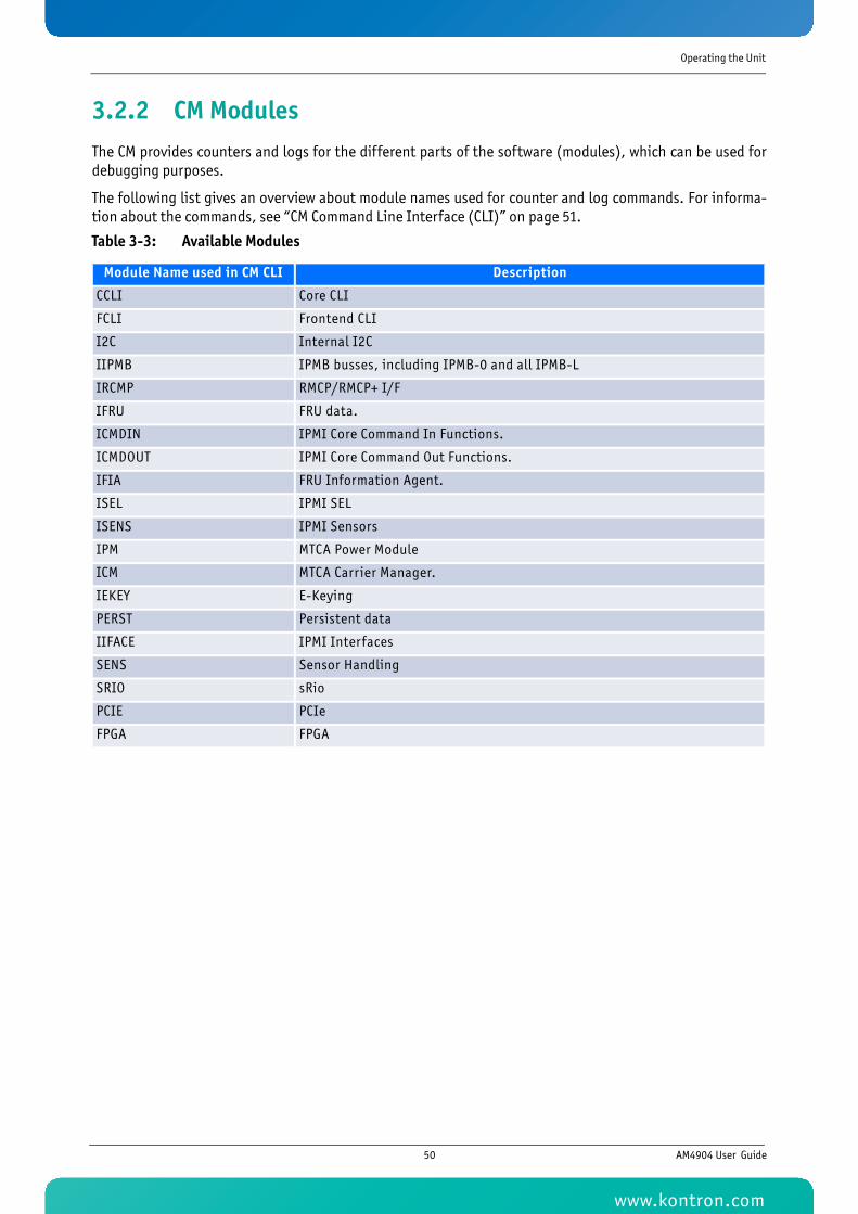
Operating the Unit
3.2.2 CM ModulesThe CM provides counters and logs for the different parts of the software (modules), which can be used fordebugging purposes.
The following list gives an overview about module names used for counter and log commands. For informa-tion about the commands, see “CM Command Line Interface (CLI)” on page 51.
Table 3-3: Available Modules
Module Name used in CM CLI Description
CCLI Core CLI
FCLI Frontend CLI
I2C Internal I2C
IIPMB IPMB busses, including IPMB-0 and all IPMB-L
IRCMP RMCP/RMCP+ I/F
IFRU FRU data.
ICMDIN IPMI Core Command In Functions.
ICMDOUT IPMI Core Command Out Functions.
IFIA FRU Information Agent.
ISEL IPMI SEL
ISENS IPMI Sensors
IPM MTCA Power Module
ICM MTCA Carrier Manager.
IEKEY E-Keying
PERST Persistent data
IIFACE IPMI Interfaces
SENS Sensor Handling
SRIO sRio
PCIE PCIe
FPGA FPGA
50 AM4904 User Guide
www.kontron.com
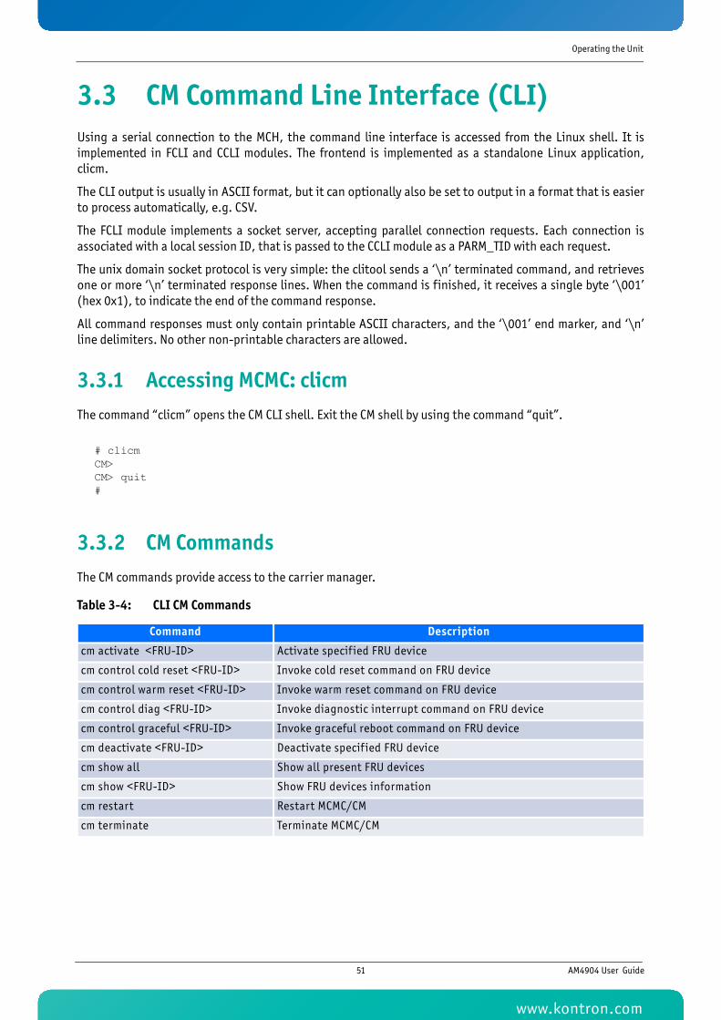
Operating the Unit
3.3 CM Command Line Interface (CLI)Using a serial connection to the MCH, the command line interface is accessed from the Linux shell. It isimplemented in FCLI and CCLI modules. The frontend is implemented as a standalone Linux application,clicm.
The CLI output is usually in ASCII format, but it can optionally also be set to output in a format that is easierto process automatically, e.g. CSV.
The FCLI module implements a socket server, accepting parallel connection requests. Each connection isassociated with a local session ID, that is passed to the CCLI module as a PARM_TID with each request.
The unix domain socket protocol is very simple: the clitool sends a ‘\n’ terminated command, and retrievesone or more ‘\n’ terminated response lines. When the command is finished, it receives a single byte ‘\001’(hex 0x1), to indicate the end of the command response.
All command responses must only contain printable ASCII characters, and the ‘\001’ end marker, and ‘\n’line delimiters. No other non-printable characters are allowed.
3.3.1 Accessing MCMC: clicmThe command “clicm” opens the CM CLI shell. Exit the CM shell by using the command “quit”.
# clicmCM>CM> quit#
3.3.2 CM CommandsThe CM commands provide access to the carrier manager.
Table 3-4: CLI CM Commands
Command Description
cm activate <FRU-ID> Activate specif ied FRU device
cm control cold reset <FRU-ID> Invoke cold reset command on FRU device
cm control warm reset <FRU-ID> Invoke warm reset command on FRU device
cm control diag <FRU-ID> Invoke diagnostic interrupt command on FRU device
cm control graceful <FRU-ID> Invoke graceful reboot command on FRU device
cm deactivate <FRU-ID> Deactivate specif ied FRU device
cm show all Show all present FRU devices
cm show <FRU-ID> Show FRU devices information
cm restart Restart MCMC/CM
cm terminate Terminate MCMC/CM
51 AM4904 User Guide
www.kontron.com
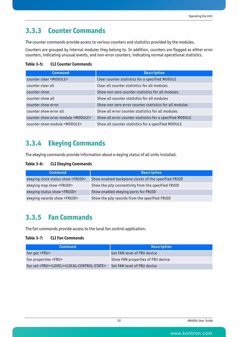
Operating the Unit
3.3.3 Counter CommandsThe counter commands provide access to various counters and statistics provided by the modules.
Counters are grouped by internal modules they belong to. In addition, counters are flagged as either errorcounters, indicating unusual events, and non-error counters, indicating normal operational statistics.
3.3.4 Ekeying CommandsThe ekeying commands provide information about e-keying status of all units installed.
3.3.5 Fan CommandsThe fan commands provide access to the local fan control application.
Table 3-5: CLI Counter Commands
Command Description
counter clear <MODULE> Clear counter statistics for a specif ied MODULE
counter clear all Clear all counter statistics for all modules
counter show Show non zero counter statistics for all modules
counter show all Show all counter statistics for all modules
counter show error Show non zero error counter statistics for all modules
counter show error all Show all error counter statistics for all modules
counter show error module <MODULE> Show all error counter statistics for a specif ied MODULE
counter show module <MODULE> Show all counter statistics for a specif ied MODULE
Table 3-6: CLI Ekeying Commands
Command Description
ekeying clock status show <FRUID> Show enabled backplane clocks of the specif ied FRUID
ekeying map show <FRUID> Show the p2p connectivity from the specif ied FRUID
ekeying status show <FRUID> Show enabled ekeying ports for FRUID
ekeying records show <FRUID> Show the p2p records from the specif ied FRUID
Table 3-7: CLI Fan Commands
Command Description
fan get <FRU> Get FAN level of FRU device
fan properties <FRU> Show FAN properties of FRU device
fan set <FRU><LEVEL><LOCAL-CONTROL-STATE> Set FAN level of FRU device
52 AM4904 User Guide
www.kontron.com
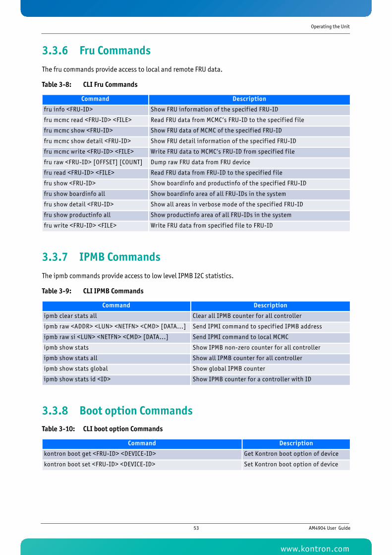
Operating the Unit
3.3.6 Fru CommandsThe fru commands provide access to local and remote FRU data.
3.3.7 IPMB CommandsThe ipmb commands provide access to low level IPMB I2C statistics.
3.3.8 Boot option Commands
Table 3-8: CLI Fru Commands
Command Description
fru info <FRU-ID> Show FRU information of the specif ied FRU-ID
fru mcmc read <FRU-ID> <FILE> Read FRU data from MCMC‘s FRU-ID to the specif ied f ile
fru mcmc show <FRU-ID> Show FRU data of MCMC of the specif ied FRU-ID
fru mcmc show detail <FRU-ID> Show FRU detail information of the specif ied FRU-ID
fru mcmc write <FRU-ID> <FILE> Write FRU data to MCMC‘s FRU-ID from specif ied f ile
fru raw <FRU-ID> [OFFSET] [COUNT] Dump raw FRU data from FRU device
fru read <FRU-ID> <FILE> Read FRU data from FRU-ID to the specif ied f ile
fru show <FRU-ID> Show boardinfo and productinfo of the specif ied FRU-ID
fru show boardinfo all Show boardinfo area of all FRU-IDs in the system
fru show detail <FRU-ID> Show all areas in verbose mode of the specif ied FRU-ID
fru show productinfo all Show productinfo area of all FRU-IDs in the system
fru write <FRU-ID> <FILE> Write FRU data from specif ied f ile to FRU-ID
Table 3-9: CLI IPMB Commands
Command Description
ipmb clear stats all Clear all IPMB counter for all controller
ipmb raw <ADDR> <LUN> <NETFN> <CMD> [DATA...] Send IPMI command to specif ied IPMB address
ipmb raw si <LUN> <NETFN> <CMD> [DATA...] Send IPMI command to local MCMC
ipmb show stats Show IPMB non-zero counter for all controller
ipmb show stats all Show all IPMB counter for all controller
ipmb show stats global Show global IPMB counter
ipmb show stats id <ID> Show IPMB counter for a controller with ID
Table 3-10: CLI boot option Commands
Command Description
kontron boot get <FRU-ID> <DEVICE-ID> Get Kontron boot option of device
kontron boot set <FRU-ID> <DEVICE-ID> Set Kontron boot option of device
53 AM4904 User Guide
www.kontron.com
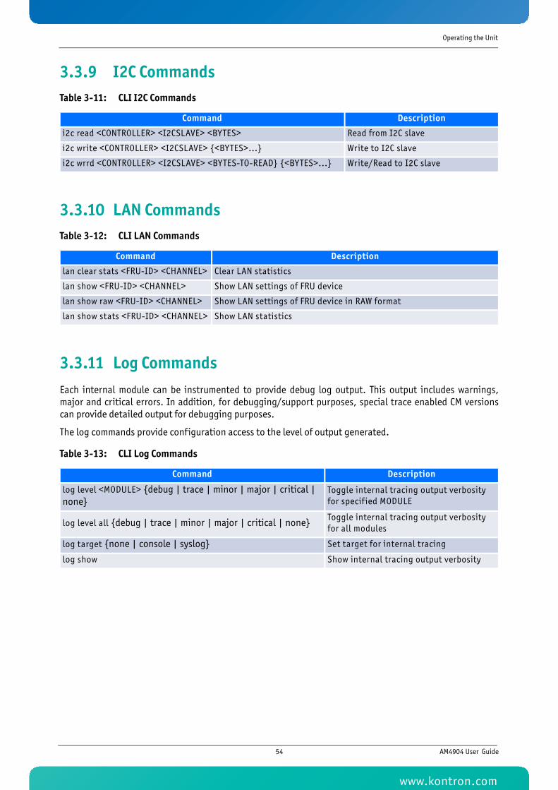
Operating the Unit
3.3.9 I2C Commands
3.3.10 LAN Commands
3.3.11 Log CommandsEach internal module can be instrumented to provide debug log output. This output includes warnings,major and critical errors. In addition, for debugging/support purposes, special trace enabled CM versionscan provide detailed output for debugging purposes.
The log commands provide configuration access to the level of output generated.
Table 3-11: CLI I2C Commands
Command Description
i2c read <CONTROLLER> <I2CSLAVE> <BYTES> Read from I2C slave
i2c write <CONTROLLER> <I2CSLAVE> {<BYTES>...} Write to I2C slave
i2c wrrd <CONTROLLER> <I2CSLAVE> <BYTES-TO-READ} {<BYTES>...} Write/Read to I2C slave
Table 3-12: CLI LAN Commands
Command Description
lan clear stats <FRU-ID> <CHANNEL> Clear LAN statistics
lan show <FRU-ID> <CHANNEL> Show LAN settings of FRU device
lan show raw <FRU-ID> <CHANNEL> Show LAN settings of FRU device in RAW format
lan show stats <FRU-ID> <CHANNEL> Show LAN statistics
Table 3-13: CLI Log Commands
Command Description
log level <MODULE> {debug | trace | minor | major | critical | none}
Toggle internal tracing output verbosity for specif ied MODULE
log level all {debug | trace | minor | major | critical | none} Toggle internal tracing output verbosity for all modules
log target {none | console | syslog} Set target for internal tracing
log show Show internal tracing output verbosity
54 AM4904 User Guide
www.kontron.com
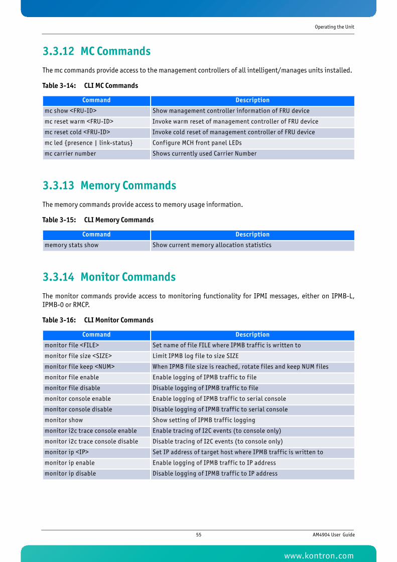
Operating the Unit
3.3.12 MC CommandsThe mc commands provide access to the management controllers of all intelligent/manages units installed.
3.3.13 Memory CommandsThe memory commands provide access to memory usage information.
3.3.14 Monitor CommandsThe monitor commands provide access to monitoring functionality for IPMI messages, either on IPMB-L,IPMB-0 or RMCP.
Table 3-14: CLI MC Commands
Command Description
mc show <FRU-ID> Show management controller information of FRU device
mc reset warm <FRU-ID> Invoke warm reset of management controller of FRU device
mc reset cold <FRU-ID> Invoke cold reset of management controller of FRU device
mc led {presence | link-status} Configure MCH front panel LEDs
mc carrier number Shows currently used Carrier Number
Table 3-15: CLI Memory Commands
Command Description
memory stats show Show current memory allocation statistics
Table 3-16: CLI Monitor Commands
Command Description
monitor f ile <FILE> Set name of f ile FILE where IPMB traff ic is written to
monitor f ile size <SIZE> Limit IPMB log f ile to size SIZE
monitor f ile keep <NUM> When IPMB f ile size is reached, rotate f iles and keep NUM files
monitor f ile enable Enable logging of IPMB traff ic to f ile
monitor f ile disable Disable logging of IPMB traff ic to f ile
monitor console enable Enable logging of IPMB traff ic to serial console
monitor console disable Disable logging of IPMB traff ic to serial console
monitor show Show setting of IPMB traff ic logging
monitor i2c trace console enable Enable tracing of I2C events (to console only)
monitor i2c trace console disable Disable tracing of I2C events (to console only)
monitor ip <IP> Set IP address of target host where IPMB traff ic is written to
monitor ip enable Enable logging of IPMB traff ic to IP address
monitor ip disable Disable logging of IPMB traff ic to IP address
55 AM4904 User Guide
www.kontron.com
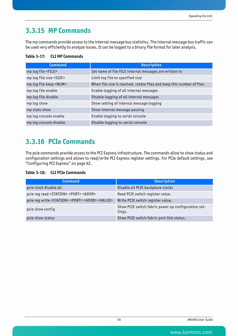
Operating the Unit
3.3.15 MP CommandsThe mp commands provide access to the internal message bus statistics. The internal message bus traffic canbe used very efficiently to analyze issues. It can be logged to a binary file format for later analysis.
3.3.16 PCIe CommandsThe pcie commands provide access to the PCI Express infrastructure. The commands allow to show status andconfiguration settings and allows to read/write PCI Express register settings. For PCIe default settings, see“Configuring PCI Express” on page 62.
Table 3-17: CLI MP Commands
Command Description
mp log f ile <FILE> Set name of f ile FILE internal messages are written to
mp log f ile size <SIZE> Limit log f ile to specif ied size
mp log f ile keep <NUM> When f ile size is reached, rotate f iles and keep this number of f iles
mp log f ile enable Enable logging of all internal messages
mp log f ile disable Disable logging of all internal messages
mp log show Show setting of internal message logging
mp stats show Show internal message passing
mp log console enable Enable logging to serial console
mp log console disable Disable logging to serial console
Table 3-18: CLI PCIe Commands
Command Description
pcie clock disable all Disable all PCIE backplane clocks
pcie reg read <STATION> <PORT> <ADDR> Read PCIE switch register value.
pcie reg write <STATION> <PORT> <ADDR> <VALUE> Write PCIE switch register value.
pcie show configShow PCIE switch fabric power up configuration set-tings.
pcie show status Show PCIE switch fabric port link status.
56 AM4904 User Guide
www.kontron.com
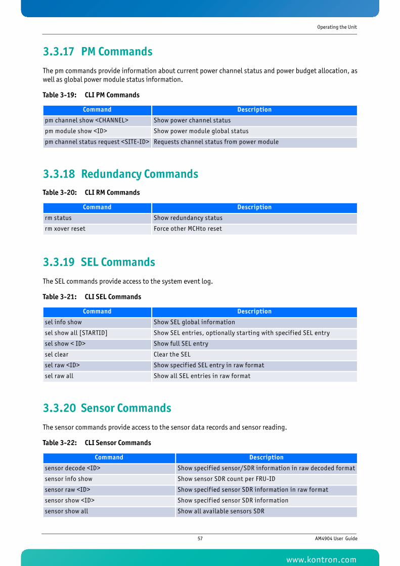
Operating the Unit
3.3.17 PM CommandsThe pm commands provide information about current power channel status and power budget allocation, aswell as global power module status information.
3.3.18 Redundancy Commands
3.3.19 SEL CommandsThe SEL commands provide access to the system event log.
3.3.20 Sensor CommandsThe sensor commands provide access to the sensor data records and sensor reading.
Table 3-19: CLI PM Commands
Command Description
pm channel show <CHANNEL> Show power channel status
pm module show <ID> Show power module global status
pm channel status request <SITE-ID> Requests channel status from power module
Table 3-20: CLI RM Commands
Command Description
rm status Show redundancy status
rm xover reset Force other MCHto reset
Table 3-21: CLI SEL Commands
Command Description
sel info show Show SEL global information
sel show all [STARTID] Show SEL entries, optionally starting with specif ied SEL entry
sel show < ID> Show full SEL entry
sel clear Clear the SEL
sel raw <ID> Show specif ied SEL entry in raw format
sel raw all Show all SEL entries in raw format
Table 3-22: CLI Sensor Commands
Command Description
sensor decode <ID> Show specif ied sensor/SDR information in raw decoded format
sensor info show Show sensor SDR count per FRU-ID
sensor raw <ID> Show specif ied sensor SDR information in raw format
sensor show <ID> Show specif ied sensor SDR information
sensor show all Show all available sensors SDR
57 AM4904 User Guide
www.kontron.com
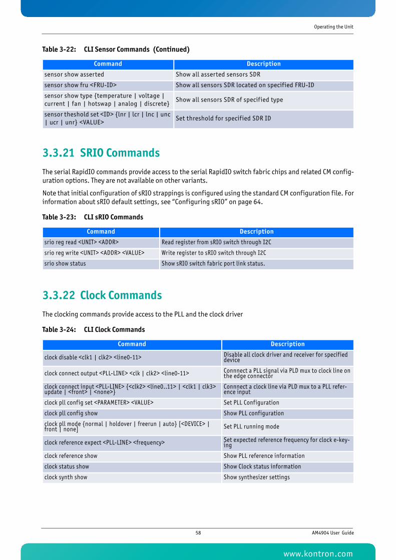
Operating the Unit
3.3.21 SRIO CommandsThe serial RapidIO commands provide access to the serial RapidIO switch fabric chips and related CM config-uration options. They are not available on other variants.
Note that initial configuration of sRIO strappings is configured using the standard CM configuration file. Forinformation about sRIO default settings, see “Configuring sRIO” on page 64.
3.3.22 Clock CommandsThe clocking commands provide access to the PLL and the clock driver
sensor show asserted Show all asserted sensors SDR
sensor show fru <FRU-ID> Show all sensors SDR located on specif ied FRU-ID
sensor show type {temperature | voltage | current | fan | hotswap | analog | discrete}
Show all sensors SDR of specif ied type
sensor theshold set <ID> {lnr | lcr | lnc | unc | ucr | unr} <VALUE>
Set threshold for specif ied SDR ID
Table 3-23: CLI sRIO Commands
Command Description
srio reg read <UNIT> <ADDR> Read register from sRIO switch through I2C
srio reg write <UNIT> <ADDR> <VALUE> Write register to sRIO switch through I2C
srio show status Show sRIO switch fabric port link status.
Table 3-24: CLI Clock Commands
Command Description
clock disable <clk1 | clk2> <line0-11> Disable all clock driver and receiver for specif ied device
clock connect output <PLL-LINE> <clk | clk2> <line0-11> Connnect a PLL signal via PLD mux to clock line on the edge connector
clock connect input <PLL-LINE> {<clk2> <line0..11> | <clk1 | clk3> update | <front> | <none>}
Connnect a clock line via PLD mux to a PLL refer-ence input
clock pll config set <PARAMETER> <VALUE> Set PLL Configuration
clock pll config show Show PLL configuration
clock pll mode {normal | holdover | freerun | auto} [<DEVICE> | front | none] Set PLL running mode
clock reference expect <PLL-LINE> <frequency> Set expected reference frequency for clock e-key-ing
clock reference show Show PLL reference information
clock status show Show Clock status information
clock synth show Show synthesizer settings
Table 3-22: CLI Sensor Commands (Continued)
Command Description
58 AM4904 User Guide
www.kontron.com
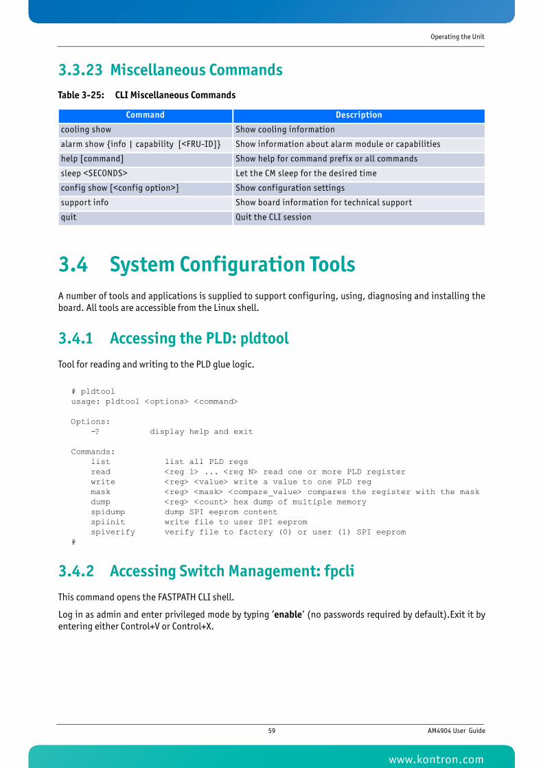
Operating the Unit
3.3.23 Miscellaneous Commands
3.4 System Configuration ToolsA number of tools and applications is supplied to support configuring, using, diagnosing and installing theboard. All tools are accessible from the Linux shell.
3.4.1 Accessing the PLD: pldtoolTool for reading and writing to the PLD glue logic.
# pldtoolusage: pldtool <options> <command>
Options: -? display help and exit
Commands: list list all PLD regs read <reg 1> ... <reg N> read one or more PLD register write <reg> <value> write a value to one PLD reg mask <reg> <mask> <compare_value> compares the register with the mask dump <reg> <count> hex dump of multiple memory spidump dump SPI eeprom content spiinit write file to user SPI eeprom spiverify verify file to factory (0) or user (1) SPI eeprom#
3.4.2 Accessing Switch Management: fpcliThis command opens the FASTPATH CLI shell.
Log in as admin and enter privileged mode by typing ’enable’ (no passwords required by default).Exit it byentering either Control+V or Control+X.
Table 3-25: CLI Miscellaneous Commands
Command Description
cooling show Show cooling information
alarm show {info | capability [<FRU-ID]} Show information about alarm module or capabilities
help [command] Show help for command pref ix or all commands
sleep <SECONDS> Let the CM sleep for the desired time
config show [<config option>] Show configuration settings
support info Show board information for technical support
quit Quit the CLI session
59 AM4904 User Guide
www.kontron.com
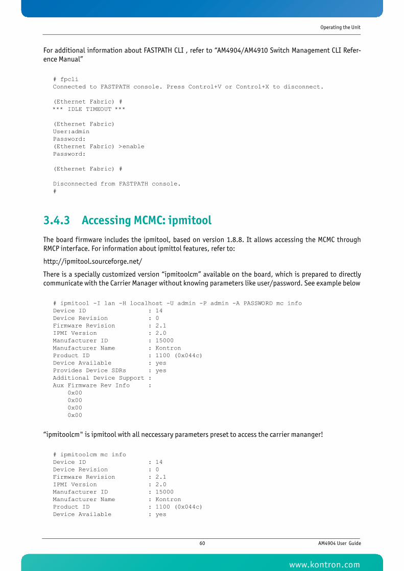
Operating the Unit
For additional information about FASTPATH CLI , refer to “AM4904/AM4910 Switch Management CLI Refer-ence Manual”
# fpcliConnected to FASTPATH console. Press Control+V or Control+X to disconnect.
(Ethernet Fabric) #*** IDLE TIMEOUT ***
(Ethernet Fabric) User:adminPassword:(Ethernet Fabric) >enablePassword:
(Ethernet Fabric) #
Disconnected from FASTPATH console.#
3.4.3 Accessing MCMC: ipmitoolThe board firmware includes the ipmitool, based on version 1.8.8. It allows accessing the MCMC throughRMCP interface. For information about ipmittol features, refer to:
http://ipmitool.sourceforge.net/
There is a specially customized version “ipmitoolcm” available on the board, which is prepared to directlycommunicate with the Carrier Manager without knowing parameters like user/password. See example below
# ipmitool -I lan -H localhost -U admin -P admin -A PASSWORD mc infoDevice ID : 14Device Revision : 0Firmware Revision : 2.1IPMI Version : 2.0Manufacturer ID : 15000Manufacturer Name : KontronProduct ID : 1100 (0x044c)Device Available : yesProvides Device SDRs : yesAdditional Device Support :Aux Firmware Rev Info : 0x00 0x00 0x00 0x00
“ipmitoolcm" is ipmitool with all neccessary parameters preset to access the carrier mananger!
# ipmitoolcm mc infoDevice ID : 14Device Revision : 0Firmware Revision : 2.1IPMI Version : 2.0Manufacturer ID : 15000Manufacturer Name : KontronProduct ID : 1100 (0x044c)Device Available : yes
60 AM4904 User Guide
www.kontron.com
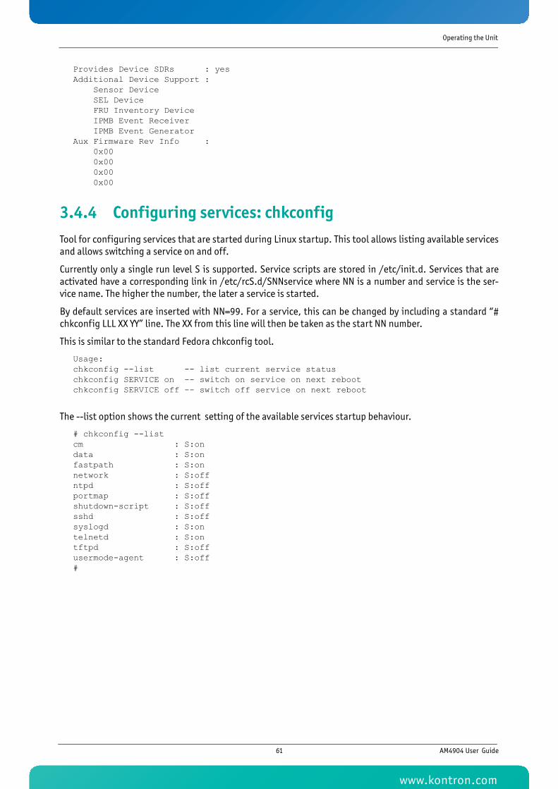
Operating the Unit
Provides Device SDRs : yesAdditional Device Support : Sensor Device SEL Device FRU Inventory Device IPMB Event Receiver IPMB Event GeneratorAux Firmware Rev Info : 0x00 0x00 0x00 0x00
3.4.4 Configuring services: chkconfigTool for configuring services that are started during Linux startup. This tool allows listing available servicesand allows switching a service on and off.
Currently only a single run level S is supported. Service scripts are stored in /etc/init.d. Services that areactivated have a corresponding link in /etc/rcS.d/SNNservice where NN is a number and service is the ser-vice name. The higher the number, the later a service is started.
By default services are inserted with NN=99. For a service, this can be changed by including a standard “#chkconfig LLL XX YY” line. The XX from this line will then be taken as the start NN number.
This is similar to the standard Fedora chkconfig tool.
Usage:chkconfig --list -- list current service statuschkconfig SERVICE on -- switch on service on next rebootchkconfig SERVICE off -- switch off service on next reboot
The --list option shows the current setting of the available services startup behaviour.
# chkconfig --listcm : S:ondata : S:onfastpath : S:onnetwork : S:offntpd : S:offportmap : S:offshutdown-script : S:offsshd : S:offsyslogd : S:ontelnetd : S:ontftpd : S:offusermode-agent : S:off#
61 AM4904 User Guide
www.kontron.com
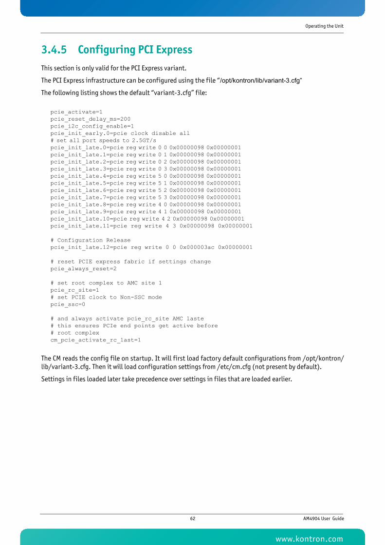
Operating the Unit
3.4.5 Configuring PCI ExpressThis section is only valid for the PCI Express variant.
The PCI Express infrastructure can be configured using the file “/opt/kontron/lib/variant-3.cfg”
The following listing shows the default “variant-3.cfg” file:
pcie_activate=1pcie_reset_delay_ms=200pcie_i2c_config_enable=1pcie_init_early.0=pcie clock disable all# set all port speeds to 2.5GT/s pcie_init_late.0=pcie reg write 0 0 0x00000098 0x00000001 pcie_init_late.1=pcie reg write 0 1 0x00000098 0x00000001 pcie_init_late.2=pcie reg write 0 2 0x00000098 0x00000001 pcie_init_late.3=pcie reg write 0 3 0x00000098 0x00000001 pcie_init_late.4=pcie reg write 5 0 0x00000098 0x00000001 pcie_init_late.5=pcie reg write 5 1 0x00000098 0x00000001 pcie_init_late.6=pcie reg write 5 2 0x00000098 0x00000001 pcie_init_late.7=pcie reg write 5 3 0x00000098 0x00000001 pcie_init_late.8=pcie reg write 4 0 0x00000098 0x00000001 pcie_init_late.9=pcie reg write 4 1 0x00000098 0x00000001 pcie_init_late.10=pcie reg write 4 2 0x00000098 0x00000001 pcie_init_late.11=pcie reg write 4 3 0x00000098 0x00000001
# Configuration Releasepcie_init_late.12=pcie reg write 0 0 0x000003ac 0x00000001
# reset PCIE express fabric if settings changepcie_always_reset=2
# set root complex to AMC site 1pcie_rc_site=1# set PCIE clock to Non-SSC modepcie_ssc=0
# and always activate pcie_rc_site AMC laste# this ensures PCIe end points get active before# root complexcm_pcie_activate_rc_last=1
The CM reads the config file on startup. It will first load factory default configurations from /opt/kontron/lib/variant-3.cfg. Then it will load configuration settings from /etc/cm.cfg (not present by default).
Settings in files loaded later take precedence over settings in files that are loaded earlier.
62 AM4904 User Guide
www.kontron.com
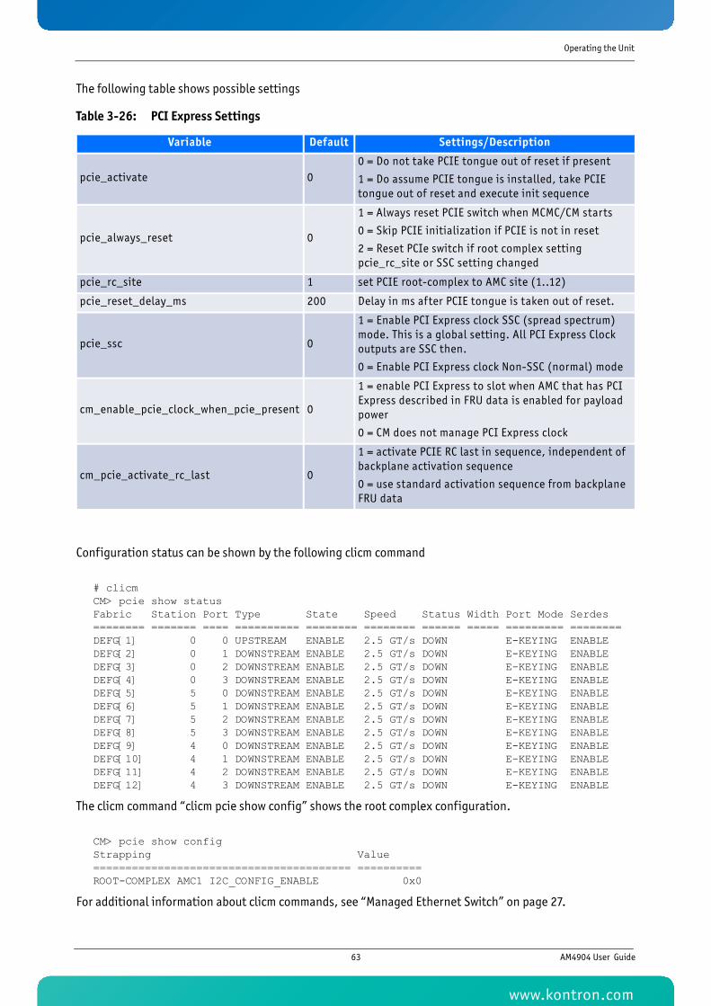
Operating the Unit
The following table shows possible settings
Configuration status can be shown by the following clicm command
# clicmCM> pcie show statusFabric Station Port Type State Speed Status Width Port Mode Serdes ======== ======= ==== ========== ======== ======== ====== ===== ========= ========DEFG[1] 0 0 UPSTREAM ENABLE 2.5 GT/s DOWN E-KEYING ENABLE DEFG[2] 0 1 DOWNSTREAM ENABLE 2.5 GT/s DOWN E-KEYING ENABLE DEFG[3] 0 2 DOWNSTREAM ENABLE 2.5 GT/s DOWN E-KEYING ENABLE DEFG[4] 0 3 DOWNSTREAM ENABLE 2.5 GT/s DOWN E-KEYING ENABLE DEFG[5] 5 0 DOWNSTREAM ENABLE 2.5 GT/s DOWN E-KEYING ENABLE DEFG[6] 5 1 DOWNSTREAM ENABLE 2.5 GT/s DOWN E-KEYING ENABLE DEFG[7] 5 2 DOWNSTREAM ENABLE 2.5 GT/s DOWN E-KEYING ENABLE DEFG[8] 5 3 DOWNSTREAM ENABLE 2.5 GT/s DOWN E-KEYING ENABLE DEFG[9] 4 0 DOWNSTREAM ENABLE 2.5 GT/s DOWN E-KEYING ENABLE DEFG[10] 4 1 DOWNSTREAM ENABLE 2.5 GT/s DOWN E-KEYING ENABLE DEFG[11] 4 2 DOWNSTREAM ENABLE 2.5 GT/s DOWN E-KEYING ENABLE DEFG[12] 4 3 DOWNSTREAM ENABLE 2.5 GT/s DOWN E-KEYING ENABLE
The clicm command “clicm pcie show config” shows the root complex configuration.
CM> pcie show configStrapping Value ======================================== ==========ROOT-COMPLEX AMC1 I2C_CONFIG_ENABLE 0x0
For additional information about clicm commands, see “Managed Ethernet Switch” on page 27.
Table 3-26: PCI Express Settings
Variable Default Settings/Description
pcie_activate 00 = Do not take PCIE tongue out of reset if present
1 = Do assume PCIE tongue is installed, take PCIE tongue out of reset and execute init sequence
pcie_always_reset 0
1 = Always reset PCIE switch when MCMC/CM starts
0 = Skip PCIE initialization if PCIE is not in reset
2 = Reset PCIe switch if root complex setting pcie_rc_site or SSC setting changed
pcie_rc_site 1 set PCIE root-complex to AMC site (1..12)
pcie_reset_delay_ms 200 Delay in ms after PCIE tongue is taken out of reset.
pcie_ssc 0
1 = Enable PCI Express clock SSC (spread spectrum) mode. This is a global setting. All PCI Express Clock outputs are SSC then.
0 = Enable PCI Express clock Non-SSC (normal) mode
cm_enable_pcie_clock_when_pcie_present 0
1 = enable PCI Express to slot when AMC that has PCI Express described in FRU data is enabled for payload power
0 = CM does not manage PCI Express clock
cm_pcie_activate_rc_last 0
1 = activate PCIE RC last in sequence, independent of backplane activation sequence
0 = use standard activation sequence from backplane FRU data
63 AM4904 User Guide
www.kontron.com
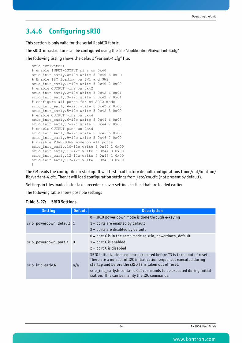
Operating the Unit
3.4.6 Configuring sRIOThis section is only valid for the serial RapidIO fabric.
The sRIO infrastructure can be configured using the file “/opt/kontron/lib/variant-4.cfg”
The following listing shows the default “variant-4.cfg” file:
srio_activate=1 # enable INPUT/OUTPUT pins on 0x40srio_init_early.0=i2c write 5 0x40 6 0xDD# Enable I2C loading on SW1 and SW2 srio_init_early.1=i2c write 5 0x40 2 0x00# enable OUTPUT pins on 0x42 srio_init_early.2=i2c write 5 0x42 6 0x01srio_init_early.3=i2c write 5 0x42 7 0x01# configure all ports for x4 SRIO mode srio_init_early.4=i2c write 5 0x42 2 0x00srio_init_early.5=i2c write 5 0x42 3 0x00# enable OUTPUT pins on 0x44 srio_init_early.6=i2c write 5 0x44 6 0x03srio_init_early.7=i2c write 5 0x44 7 0x00# enable OUTPUT pins on 0x46 srio_init_early.8=i2c write 5 0x46 6 0x03srio_init_early.9=i2c write 5 0x46 7 0x00# disable POWERDOWN mode on all ports srio_init_early.10=i2c write 5 0x44 2 0x00srio_init_early.11=i2c write 5 0x44 3 0x00srio_init_early.12=i2c write 5 0x46 2 0x00srio_init_early.13=i2c write 5 0x46 3 0x00#
The CM reads the config file on startup. It will first load factory default configurations from /opt/kontron/lib/variant-4.cfg. Then it will load configuration settings from /etc/cm.cfg (not present by default).
Settings in files loaded later take precedence over settings in files that are loaded earlier.
The following table shows possible settings
Table 3-27: SRIO Settings
Setting Default Description
srio_powerdown_default 1
0 = sRIO power down mode is done through e-keying
1 = ports are enabled by default
2 = ports are disabled by default
srio_powerdown_port.X 0
0 = port X is in the same mode as srio_powerdown_default
1 = port X is enabled
2 = port X is disabled
srio_init_early.N n/a
SRIO initialization sequence executed before T3 is taken out of reset. There are a number of I2C initialization sequences executed during startup and before the sRIO T3 is taken out of reset.
srio_init_early.N contains CLI commands to be executed during initial-ization. This can be mainly the I2C commands.
64 AM4904 User Guide
www.kontron.com
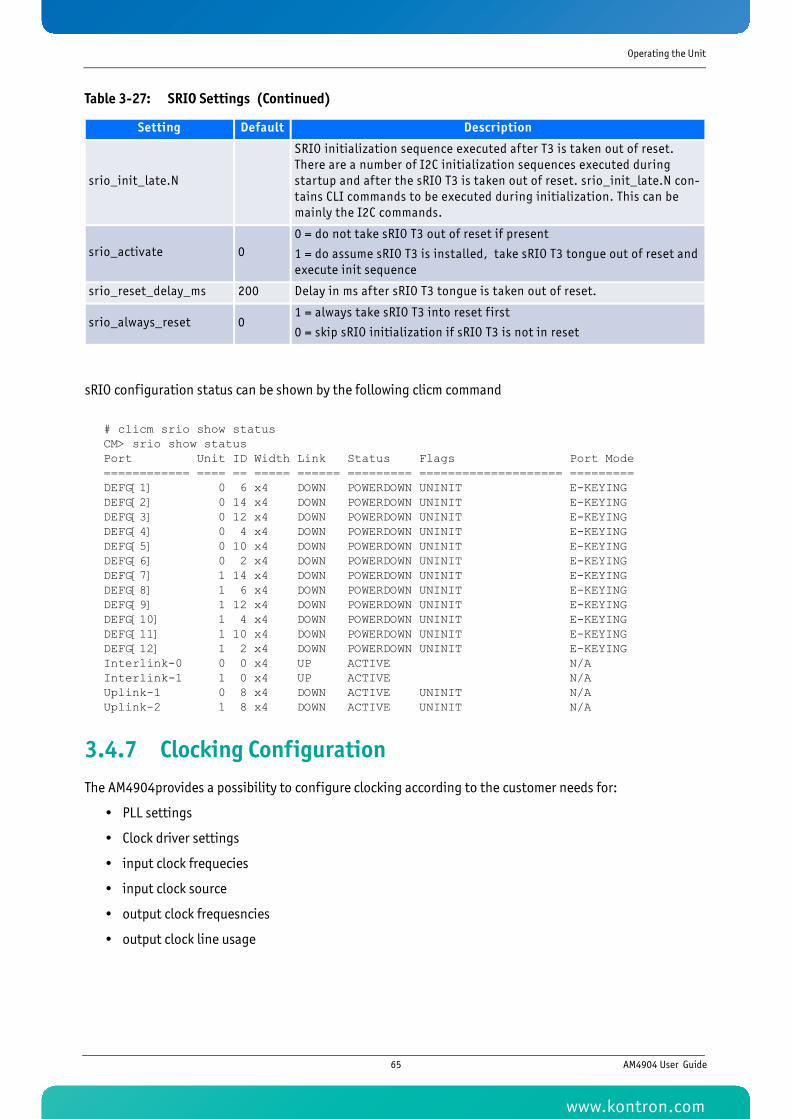
Operating the Unit
sRIO configuration status can be shown by the following clicm command
# clicm srio show statusCM> srio show statusPort Unit ID Width Link Status Flags Port Mode============ ==== == ===== ====== ========= ==================== =========DEFG[1] 0 6 x4 DOWN POWERDOWN UNINIT E-KEYING DEFG[2] 0 14 x4 DOWN POWERDOWN UNINIT E-KEYING DEFG[3] 0 12 x4 DOWN POWERDOWN UNINIT E-KEYING DEFG[4] 0 4 x4 DOWN POWERDOWN UNINIT E-KEYING DEFG[5] 0 10 x4 DOWN POWERDOWN UNINIT E-KEYING DEFG[6] 0 2 x4 DOWN POWERDOWN UNINIT E-KEYING DEFG[7] 1 14 x4 DOWN POWERDOWN UNINIT E-KEYING DEFG[8] 1 6 x4 DOWN POWERDOWN UNINIT E-KEYING DEFG[9] 1 12 x4 DOWN POWERDOWN UNINIT E-KEYING DEFG[10] 1 4 x4 DOWN POWERDOWN UNINIT E-KEYING DEFG[11] 1 10 x4 DOWN POWERDOWN UNINIT E-KEYING DEFG[12] 1 2 x4 DOWN POWERDOWN UNINIT E-KEYING Interlink-0 0 0 x4 UP ACTIVE N/AInterlink-1 1 0 x4 UP ACTIVE N/AUplink-1 0 8 x4 DOWN ACTIVE UNINIT N/AUplink-2 1 8 x4 DOWN ACTIVE UNINIT N/A
3.4.7 Clocking ConfigurationThe AM4904provides a possibility to configure clocking according to the customer needs for:
• PLL settings
• Clock driver settings
• input clock frequecies
• input clock source
• output clock frequesncies
• output clock line usage
srio_init_late.N
SRIO initialization sequence executed after T3 is taken out of reset. There are a number of I2C initialization sequences executed during startup and after the sRIO T3 is taken out of reset. srio_init_late.N con-tains CLI commands to be executed during initialization. This can be mainly the I2C commands.
srio_activate 00 = do not take sRIO T3 out of reset if present
1 = do assume sRIO T3 is installed, take sRIO T3 tongue out of reset and execute init sequence
srio_reset_delay_ms 200 Delay in ms after sRIO T3 tongue is taken out of reset.
srio_always_reset 01 = always take sRIO T3 into reset f irst
0 = skip sRIO initialization if sRIO T3 is not in reset
Table 3-27: SRIO Settings (Continued)
Setting Default Description
65 AM4904 User Guide
www.kontron.com
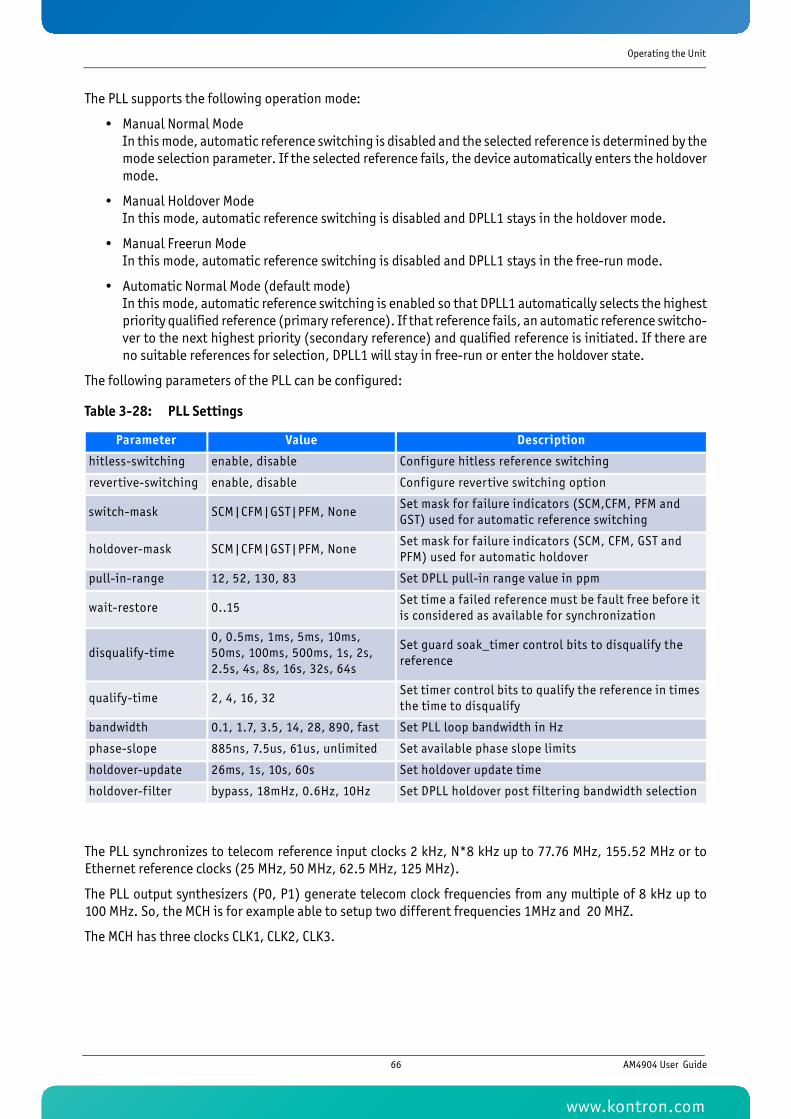
Operating the Unit
The PLL supports the following operation mode:
• Manual Normal ModeIn this mode, automatic reference switching is disabled and the selected reference is determined by themode selection parameter. If the selected reference fails, the device automatically enters the holdovermode.
• Manual Holdover ModeIn this mode, automatic reference switching is disabled and DPLL1 stays in the holdover mode.
• Manual Freerun ModeIn this mode, automatic reference switching is disabled and DPLL1 stays in the free-run mode.
• Automatic Normal Mode (default mode)In this mode, automatic reference switching is enabled so that DPLL1 automatically selects the highestpriority qualified reference (primary reference). If that reference fails, an automatic reference switcho-ver to the next highest priority (secondary reference) and qualified reference is initiated. If there areno suitable references for selection, DPLL1 will stay in free-run or enter the holdover state.
The following parameters of the PLL can be configured:
The PLL synchronizes to telecom reference input clocks 2 kHz, N*8 kHz up to 77.76 MHz, 155.52 MHz or toEthernet reference clocks (25 MHz, 50 MHz, 62.5 MHz, 125 MHz).
The PLL output synthesizers (P0, P1) generate telecom clock frequencies from any multiple of 8 kHz up to100 MHz. So, the MCH is for example able to setup two different frequencies 1MHz and 20 MHZ.
The MCH has three clocks CLK1, CLK2, CLK3.
Table 3-28: PLL Settings
Parameter Value Description
hitless-switching enable, disable Configure hitless reference switching
revertive-switching enable, disable Configure revertive switching option
switch-mask SCM|CFM|GST|PFM, NoneSet mask for failure indicators (SCM,CFM, PFM and GST) used for automatic reference switching
holdover-mask SCM|CFM|GST|PFM, NoneSet mask for failure indicators (SCM, CFM, GST and PFM) used for automatic holdover
pull-in-range 12, 52, 130, 83 Set DPLL pull-in range value in ppm
wait-restore 0..15Set time a failed reference must be fault free before it is considered as available for synchronization
disqualify-time0, 0.5ms, 1ms, 5ms, 10ms, 50ms, 100ms, 500ms, 1s, 2s, 2.5s, 4s, 8s, 16s, 32s, 64s
Set guard soak_timer control bits to disqualify the reference
qualify-time 2, 4, 16, 32Set timer control bits to qualify the reference in times the time to disqualify
bandwidth 0.1, 1.7, 3.5, 14, 28, 890, fast Set PLL loop bandwidth in Hz
phase-slope 885ns, 7.5us, 61us, unlimited Set available phase slope limits
holdover-update 26ms, 1s, 10s, 60s Set holdover update time
holdover-f ilter bypass, 18mHz, 0.6Hz, 10Hz Set DPLL holdover post f iltering bandwidth selection
66 AM4904 User Guide
www.kontron.com
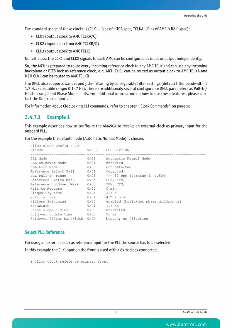
Operating the Unit
The standard usage of these clocks is (CLK1...3 as of mTCA spec, TCLKA...D as of AMC.0 R2.0 spec):
• CLK1 (output clock to AMC TCLKA/C)
• CLK2 (input clock from AMC TCLKB/D)
• CLK3 (output clock to AMC FCLK)
Nonetheless, the CLK1 and CLK2 signals to each AMC can be configured as input or output independently.
So, the MCH is prepared to route every incoming reference clock to any AMC TCLK and can use any incomingbackplane or BITS lock as reference clock, e.g. MCH CLK1 can be routed as output clock to AMC TCLKA andMCH CLK2 can be routed to AMC TCLKB.
The DPLL also supports wander and jitter filtering by configurable filter settings (default filter bandwidth is1.7 Hz, selectable range: 0.1- 7 Hz). There are additionaly several configurable DPLL parameters as Pull-In/Hold-in range and Phase Slope Linits. For additional information on how to use these features, please con-tact the Kontron support.
For information about CM clocking CLI commands, refer to chapter "Clock Commands" on page 58.
3.4.7.1 Example 1
This example describes how to configure the AM4904 to receive an external clock as primary input for theonboard PLL.
For the example the default mode (Automatic Normal Mode) is chosen.
clicm clock config showSTATUS VALUE DESCRIPTION========================== ======== ===============================================PLL Mode 0x03 Automatic Normal ModePLL Holdover Mode 0x01 detectedPLL Lock Mode 0x00 not detectedReference Select Fail 0x01 detectedPLL Pull-in range 0x03 +/- 83 ppm (Stratum 4, G.824)Reference Switch Mask 0x0c GST, PFM,Reference Holdover Mask 0x03 SCM, CFM,Wait to Restore 0x00 0 minDisqualify time 0x0a 2.5 sQualify time 0x01 4 * 2.5 sHitless Switching 0x00 enabled (build-out phase differents)Bandwidth 0x01 1.7 HzPhase slope limits 0x03 unlimitedHoldover update time 0x00 26 msHoldover filter bandwidth 0x00 bypass, no filtering
Select PLL Reference
For using an external clock as reference input for the PLL the source has to be selected.
In this example the CLK input on the front is used with a 8kHz clock connected.
# clicm clock reference primary front
67 AM4904 User Guide
www.kontron.com
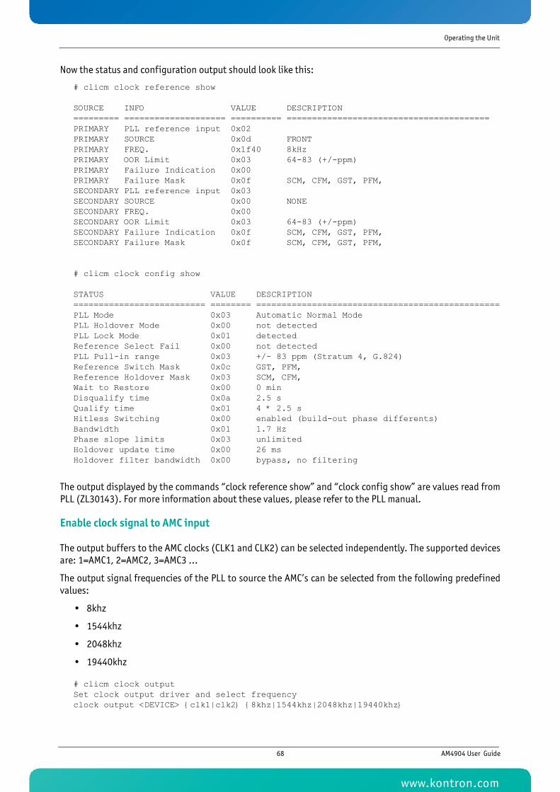
Operating the Unit
Now the status and configuration output should look like this:
# clicm clock reference show
SOURCE INFO VALUE DESCRIPTION========= ==================== ========== ========================================PRIMARY PLL reference input 0x02PRIMARY SOURCE 0x0d FRONTPRIMARY FREQ. 0x1f40 8kHzPRIMARY OOR Limit 0x03 64-83 (+/-ppm)PRIMARY Failure Indication 0x00PRIMARY Failure Mask 0x0f SCM, CFM, GST, PFM,SECONDARY PLL reference input 0x03SECONDARY SOURCE 0x00 NONESECONDARY FREQ. 0x00SECONDARY OOR Limit 0x03 64-83 (+/-ppm)SECONDARY Failure Indication 0x0f SCM, CFM, GST, PFM,SECONDARY Failure Mask 0x0f SCM, CFM, GST, PFM,
# clicm clock config show
STATUS VALUE DESCRIPTION========================== ======== ================================================PLL Mode 0x03 Automatic Normal ModePLL Holdover Mode 0x00 not detectedPLL Lock Mode 0x01 detectedReference Select Fail 0x00 not detectedPLL Pull-in range 0x03 +/- 83 ppm (Stratum 4, G.824)Reference Switch Mask 0x0c GST, PFM,Reference Holdover Mask 0x03 SCM, CFM,Wait to Restore 0x00 0 minDisqualify time 0x0a 2.5 sQualify time 0x01 4 * 2.5 sHitless Switching 0x00 enabled (build-out phase differents)Bandwidth 0x01 1.7 HzPhase slope limits 0x03 unlimitedHoldover update time 0x00 26 msHoldover filter bandwidth 0x00 bypass, no filtering
The output displayed by the commands “clock reference show” and “clock config show” are values read fromPLL (ZL30143). For more information about these values, please refer to the PLL manual.
Enable clock signal to AMC input
The output buffers to the AMC clocks (CLK1 and CLK2) can be selected independently. The supported devicesare: 1=AMC1, 2=AMC2, 3=AMC3 …
The output signal frequencies of the PLL to source the AMC’s can be selected from the following predefinedvalues:
• 8khz
• 1544khz
• 2048khz
• 19440khz
# clicm clock outputSet clock output driver and select frequencyclock output <DEVICE> {clk1|clk2} {8khz|1544khz|2048khz|19440khz}
68 AM4904 User Guide
www.kontron.com
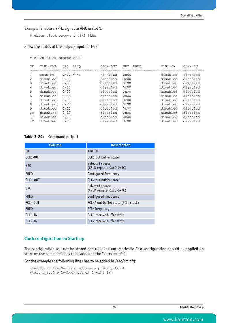
Operating the Unit
Example: Enable a 8kHz signal to AMC in slot 1:
# clicm clock output 1 clk1 8khz
Show the status of the output/input buffers:
# clicm clock status show
ID CLK1-OUT SRC FREQ CLK2-OUT SRC FREQ CLK1-IN CLK2-IN ==== ========== ==== ========== == ========== ==== ========== == ========== ==========1 enabled 0x09 8kHz disabled 0x00 disabled disabled 2 disabled 0x00 disabled 0x00 disabled disabled 3 disabled 0x00 disabled 0x00 disabled disabled 4 disabled 0x00 disabled 0x00 disabled disabled 5 disabled 0x00 disabled 0x00 disabled disabled 6 disabled 0x00 disabled 0x00 disabled disabled 7 disabled 0x00 disabled 0x00 disabled disabled 8 disabled 0x00 disabled 0x00 disabled disabled 9 disabled 0x00 disabled 0x00 disabled disabled 10 disabled 0x00 disabled 0x00 disabled disabled 11 disabled 0x00 disabled 0x00 disabled disabled 12 disabled 0x00 disabled 0x00 disabled disabled
Clock configuration on Start-up
The configuration will not be stored and reloaded automatically. If a configuration should be applied onstart-up the commands has to be added in the “/etc/cm.cfg”.
For the example the following lines has to be added in /etc/cm.cfg:
startup_active.0=clock reference primary frontstartup_active.1=clock output 1 clk1 8kh
Table 3-29: Command output
Column Description
ID AMC ID
CLK1-OUT CLK1 out buffer state
SRC Selected source (CPLD register 0x60-0x6C)
FREQ Configured frequency
CLK2-OUT CLK2 out buffer state
SRC Selected source (CPLD register 0x70-0x7C)
FREQ Configured frequency
FCLK-OUT FCLKA out buffer state (PCIe clock)
FREQ PCIe frequency
CLK1-IN CLK1 receive buffer state
CLK2-IN CLK2 receive buffer state
69 AM4904 User Guide
www.kontron.com
Operating the Unit
3.4.8 MCH Redundancy SupportThe CM can be used in chassis with dual MCH slots. In this configuration, the MCH will detect the presence ofa second MCH.
If both MCH are compatible, they will switch to an active/standby mode, where the standby MCH will con-stantly monitor the active MCH using redundant communication channels. When it does detect that theactive MCH is no longer responsding, it will initiate a fail-over, will rediscover currently active modules in thechassis and will take over management of the carrier.
Two independent channels are used for communication. One is the standard redundant backplane IPMB-0.Any MCH will periodically distribute its status on the bus to the other MCH via a Kontron OEM IPMI commandsend to the MCMC. In addition, a heartbeat is sent periodically between both MCHs using a PLD interlink. Thisheartbeat is also used to detect health of the other MCH.
When both communication channels indicate a remote failure, the backup MCH may then initiate a failover.It signals this transition to the active MCH using the PLD interlink. The PLD on the active MCH will then safelyisolate/shutdown external interfaces related to carrier management on the failed MCH.
Redundancy status of the MCH will be shown using the cm command “rm status”. There is also a command(rm xover reset) that forces the redundant MCH to reset.
For additional information about CM redundance commands, see chapter Redundancy Commands.
3.4.9 Cooling Unit Management
The Carrier Manager implements an intelligent fan control that works together with MicroTCA compliant Cooling Units that are connected to the IPMB-0 bus.
Once the CM has discovered that the chassis supports cooling units it starts the fan control module. The fan control module can be forced off if the config parameter fan_control is set to zero.
70 AM4904 User Guide
www.kontron.com

Operating the Unit
The fan control module implements the following states:
Table 3-30: FAN control states
State Description Actions
NormalThe fan control is not in any other state.
The fan level is decreased in steps of fan_stepdown fan level steps each fan_dec_timeout seconds down to the dynamic fan level.
When the dynamic fan level is reached it is dec-remented each fan_dynamic_timeout seconds until fan_norm_level is reached.
Minor
The fan control is not in critical and error state and
at least one temperature sen-sor reports that the upper non-critical threshold has been crossed.
If the current fan level is equal the dynamic fan level and the previous state was normal then the dynamic fan level is increased by one.
The current fan level is increased in steps of fan_stepup fan level steps each fan_inc_timeout seconds until the maximum fan level is reached.
Critical
The fan control is not in error state and at least one tempera-ture sensor reports that the upper critical or upper non-recoverable threshold has been crossed.
If the current fan level is equal the dynamic fan level and the previous state was normal then the dynamic fan level is increased by one.
The current fan level is set to the maximum value.
Error
At least one of the cooling units is not in M4 or M5 state or the fan control module has not been discovered all cooling units or the fan control is not able to adjust the speed of a cooling unit.
The fan level is set to the maximum value until this state is left.
71 AM4904 User Guide
www.kontron.com
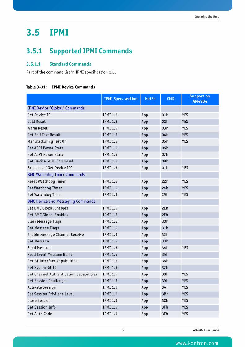
Operating the Unit
3.5 IPMI
3.5.1 Supported IPMI Commands
3.5.1.1 Standard Commands
Part of the command list in IPMI specification 1.5.
Table 3-31: IPMI Device Commands
IPMI Spec. section NetFn CMDSupport on
AM4904
IPMI Device “Global” Commands
Get Device ID IPMI 1.5 App 01h YES
Cold Reset IPMI 1.5 App 02h YES
Warm Reset IPMI 1.5 App 03h YES
Get Self Test Result IPMI 1.5 App 04h YES
Manufacturing Test On IPMI 1.5 App 05h YES
Set ACPI Power State IPMI 1.5 App 06h
Get ACPI Power State IPMI 1.5 App 07h
Get Device GUID Command IPMI 1.5 App 08h
Broadcast “Get Device ID” IPMI 1.5 App 01h YES
BMC Watchdog Timer Commands
Reset Watchdog Timer IPMI 1.5 App 22h YES
Set Watchdog Timer IPMI 1.5 App 24h YES
Get Watchdog Timer IPMI 1.5 App 25h YES
BMC Device and Messaging Commands
Set BMC Global Enables IPMI 1.5 App 2Eh
Get BMC Global Enables IPMI 1.5 App 2Fh
Clear Message Flags IPMI 1.5 App 30h
Get Message Flags IPMI 1.5 App 31h
Enable Message Channel Receive IPMI 1.5 App 32h
Get Message IPMI 1.5 App 33h
Send Message IPMI 1.5 App 34h YES
Read Event Message Buffer IPMI 1.5 App 35h
Get BT Interface Capabilities IPMI 1.5 App 36h
Get System GUID IPMI 1.5 App 37h
Get Channel Authentication Capabilities IPMI 1.5 App 38h YES
Get Session Challenge IPMI 1.5 App 39h YES
Activate Session IPMI 1.5 App 3Ah YES
Set Session Privilege Level IPMI 1.5 App 3Bh YES
Close Session IPMI 1.5 App 3Ch YES
Get Session Info IPMI 1.5 App 3Fh YES
Get Auth Code IPMI 1.5 App 3Fh YES
72 AM4904 User Guide
www.kontron.com
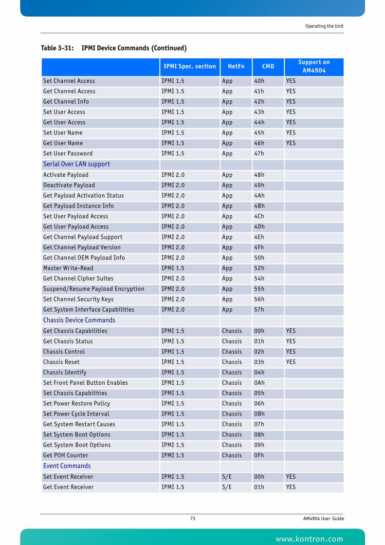
Operating the Unit
Set Channel Access IPMI 1.5 App 40h YES
Get Channel Access IPMI 1.5 App 41h YES
Get Channel Info IPMI 1.5 App 42h YES
Set User Access IPMI 1.5 App 43h YES
Get User Access IPMI 1.5 App 44h YES
Set User Name IPMI 1.5 App 45h YES
Get User Name IPMI 1.5 App 46h YES
Set User Password IPMI 1.5 App 47h
Serial Over LAN support
Activate Payload IPMI 2.0 App 48h
Deactivate Payload IPMI 2.0 App 49h
Get Payload Activation Status IPMI 2.0 App 4Ah
Get Payload Instance Info IPMI 2.0 App 4Bh
Set User Payload Access IPMI 2.0 App 4Ch
Get User Payload Access IPMI 2.0 App 4Dh
Get Channel Payload Support IPMI 2.0 App 4Eh
Get Channel Payload Version IPMI 2.0 App 4Fh
Get Channel OEM Payload Info IPMI 2.0 App 50h
Master Write-Read IPMI 1.5 App 52h
Get Channel Cipher Suites IPMI 2.0 App 54h
Suspend/Resume Payload Encryption IPMI 2.0 App 55h
Set Channel Security Keys IPMI 2.0 App 56h
Get System Interface Capabilities IPMI 2.0 App 57h
Chassis Device Commands
Get Chassis Capabilities IPMI 1.5 Chassis 00h YES
Get Chassis Status IPMI 1.5 Chassis 01h YES
Chassis Control IPMI 1.5 Chassis 02h YES
Chassis Reset IPMI 1.5 Chassis 03h YES
Chassis Identify IPMI 1.5 Chassis 04h
Set Front Panel Button Enables IPMI 1.5 Chassis 0Ah
Set Chassis Capabilities IPMI 1.5 Chassis 05h
Set Power Restore Policy IPMI 1.5 Chassis 06h
Set Power Cycle Interval IPMI 1.5 Chassis 0Bh
Get System Restart Causes IPMI 1.5 Chassis 07h
Set System Boot Options IPMI 1.5 Chassis 08h
Get System Boot Options IPMI 1.5 Chassis 09h
Get POH Counter IPMI 1.5 Chassis 0Fh
Event Commands
Set Event Receiver IPMI 1.5 S/E 00h YES
Get Event Receiver IPMI 1.5 S/E 01h YES
Table 3-31: IPMI Device Commands (Continued)
IPMI Spec. section NetFn CMDSupport on
AM4904
73 AM4904 User Guide
www.kontron.com
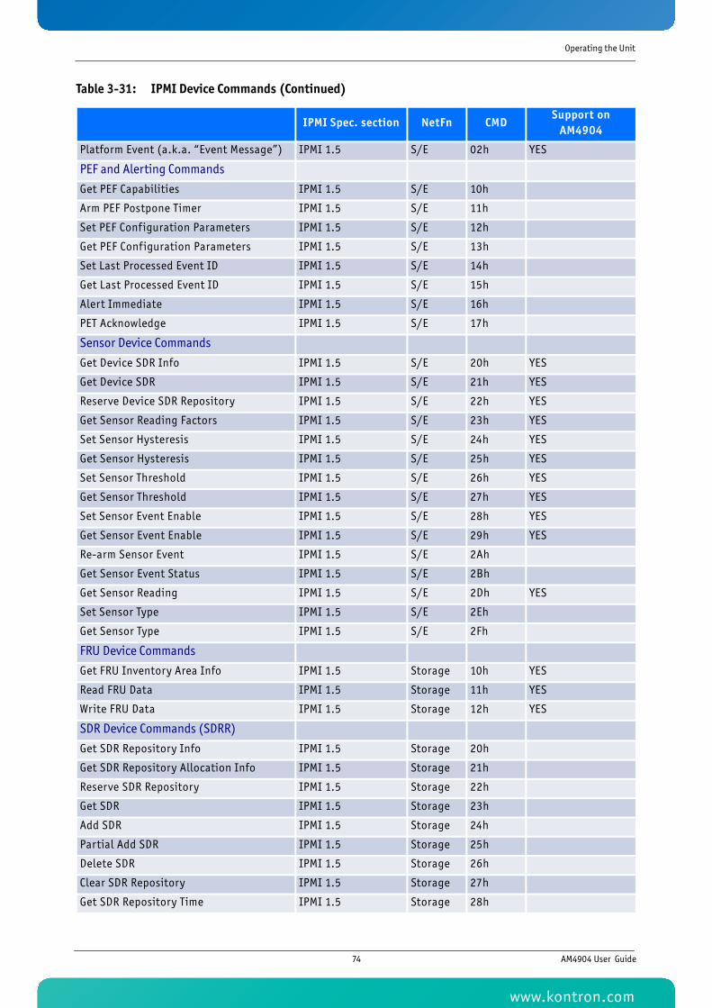
Operating the Unit
Platform Event (a.k.a. “Event Message”) IPMI 1.5 S/E 02h YES
PEF and Alerting Commands
Get PEF Capabilities IPMI 1.5 S/E 10h
Arm PEF Postpone Timer IPMI 1.5 S/E 11h
Set PEF Configuration Parameters IPMI 1.5 S/E 12h
Get PEF Configuration Parameters IPMI 1.5 S/E 13h
Set Last Processed Event ID IPMI 1.5 S/E 14h
Get Last Processed Event ID IPMI 1.5 S/E 15h
Alert Immediate IPMI 1.5 S/E 16h
PET Acknowledge IPMI 1.5 S/E 17h
Sensor Device Commands
Get Device SDR Info IPMI 1.5 S/E 20h YES
Get Device SDR IPMI 1.5 S/E 21h YES
Reserve Device SDR Repository IPMI 1.5 S/E 22h YES
Get Sensor Reading Factors IPMI 1.5 S/E 23h YES
Set Sensor Hysteresis IPMI 1.5 S/E 24h YES
Get Sensor Hysteresis IPMI 1.5 S/E 25h YES
Set Sensor Threshold IPMI 1.5 S/E 26h YES
Get Sensor Threshold IPMI 1.5 S/E 27h YES
Set Sensor Event Enable IPMI 1.5 S/E 28h YES
Get Sensor Event Enable IPMI 1.5 S/E 29h YES
Re-arm Sensor Event IPMI 1.5 S/E 2Ah
Get Sensor Event Status IPMI 1.5 S/E 2Bh
Get Sensor Reading IPMI 1.5 S/E 2Dh YES
Set Sensor Type IPMI 1.5 S/E 2Eh
Get Sensor Type IPMI 1.5 S/E 2Fh
FRU Device Commands
Get FRU Inventory Area Info IPMI 1.5 Storage 10h YES
Read FRU Data IPMI 1.5 Storage 11h YES
Write FRU Data IPMI 1.5 Storage 12h YES
SDR Device Commands (SDRR)
Get SDR Repository Info IPMI 1.5 Storage 20h
Get SDR Repository Allocation Info IPMI 1.5 Storage 21h
Reserve SDR Repository IPMI 1.5 Storage 22h
Get SDR IPMI 1.5 Storage 23h
Add SDR IPMI 1.5 Storage 24h
Partial Add SDR IPMI 1.5 Storage 25h
Delete SDR IPMI 1.5 Storage 26h
Clear SDR Repository IPMI 1.5 Storage 27h
Get SDR Repository Time IPMI 1.5 Storage 28h
Table 3-31: IPMI Device Commands (Continued)
IPMI Spec. section NetFn CMDSupport on
AM4904
74 AM4904 User Guide
www.kontron.com
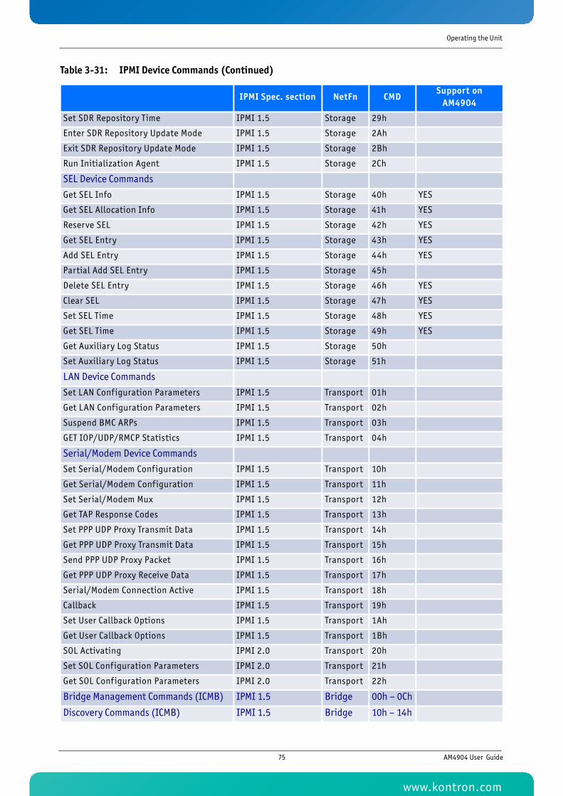
Operating the Unit
Set SDR Repository Time IPMI 1.5 Storage 29h
Enter SDR Repository Update Mode IPMI 1.5 Storage 2Ah
Exit SDR Repository Update Mode IPMI 1.5 Storage 2Bh
Run Initialization Agent IPMI 1.5 Storage 2Ch
SEL Device Commands
Get SEL Info IPMI 1.5 Storage 40h YES
Get SEL Allocation Info IPMI 1.5 Storage 41h YES
Reserve SEL IPMI 1.5 Storage 42h YES
Get SEL Entry IPMI 1.5 Storage 43h YES
Add SEL Entry IPMI 1.5 Storage 44h YES
Partial Add SEL Entry IPMI 1.5 Storage 45h
Delete SEL Entry IPMI 1.5 Storage 46h YES
Clear SEL IPMI 1.5 Storage 47h YES
Set SEL Time IPMI 1.5 Storage 48h YES
Get SEL Time IPMI 1.5 Storage 49h YES
Get Auxiliary Log Status IPMI 1.5 Storage 50h
Set Auxiliary Log Status IPMI 1.5 Storage 51h
LAN Device Commands
Set LAN Configuration Parameters IPMI 1.5 Transport 01h
Get LAN Configuration Parameters IPMI 1.5 Transport 02h
Suspend BMC ARPs IPMI 1.5 Transport 03h
GET IOP/UDP/RMCP Statistics IPMI 1.5 Transport 04h
Serial/Modem Device Commands
Set Serial/Modem Configuration IPMI 1.5 Transport 10h
Get Serial/Modem Configuration IPMI 1.5 Transport 11h
Set Serial/Modem Mux IPMI 1.5 Transport 12h
Get TAP Response Codes IPMI 1.5 Transport 13h
Set PPP UDP Proxy Transmit Data IPMI 1.5 Transport 14h
Get PPP UDP Proxy Transmit Data IPMI 1.5 Transport 15h
Send PPP UDP Proxy Packet IPMI 1.5 Transport 16h
Get PPP UDP Proxy Receive Data IPMI 1.5 Transport 17h
Serial/Modem Connection Active IPMI 1.5 Transport 18h
Callback IPMI 1.5 Transport 19h
Set User Callback Options IPMI 1.5 Transport 1Ah
Get User Callback Options IPMI 1.5 Transport 1Bh
SOL Activating IPMI 2.0 Transport 20h
Set SOL Configuration Parameters IPMI 2.0 Transport 21h
Get SOL Configuration Parameters IPMI 2.0 Transport 22h
Bridge Management Commands (ICMB) IPMI 1.5 Bridge 00h – 0Ch
Discovery Commands (ICMB) IPMI 1.5 Bridge 10h – 14h
Table 3-31: IPMI Device Commands (Continued)
IPMI Spec. section NetFn CMDSupport on
AM4904
75 AM4904 User Guide
www.kontron.com
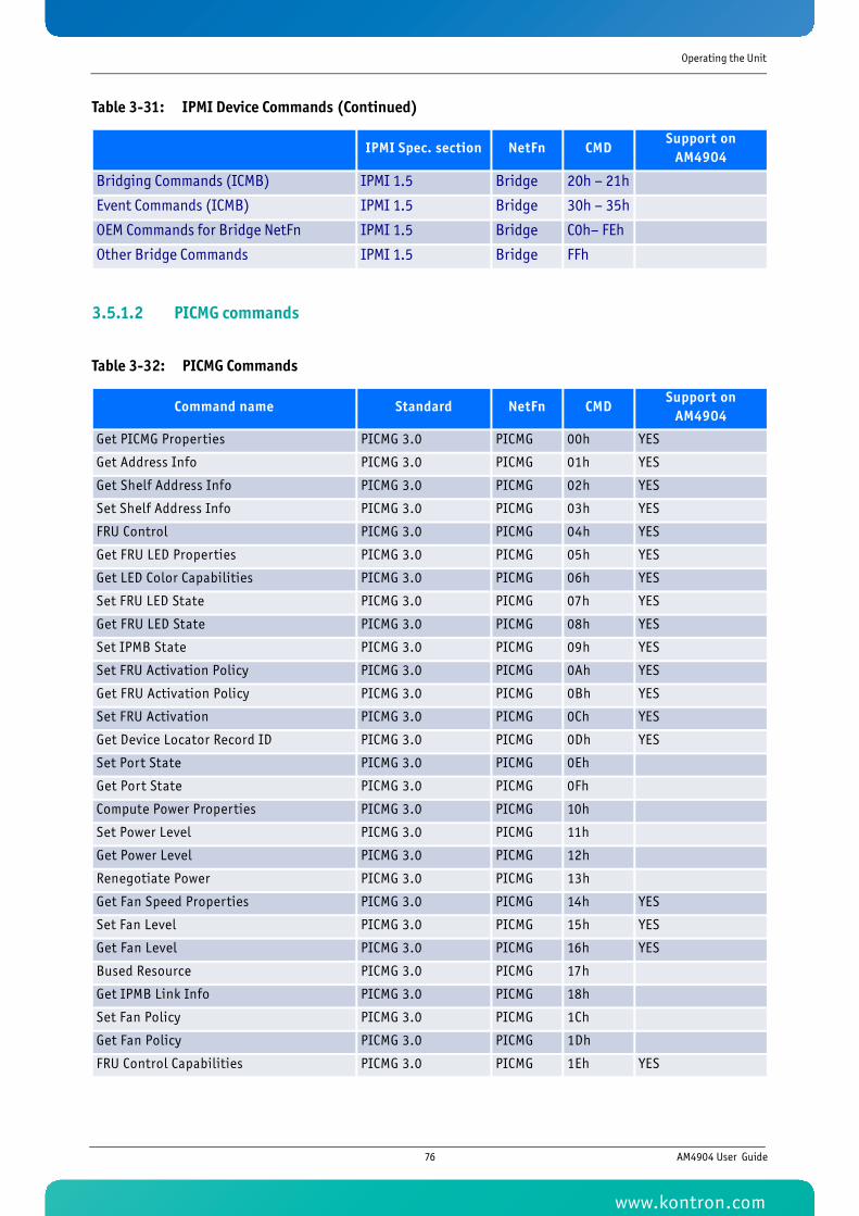
Operating the Unit
3.5.1.2 PICMG commands
Bridging Commands (ICMB) IPMI 1.5 Bridge 20h – 21h
Event Commands (ICMB) IPMI 1.5 Bridge 30h – 35h
OEM Commands for Bridge NetFn IPMI 1.5 Bridge C0h– FEh
Other Bridge Commands IPMI 1.5 Bridge FFh
Table 3-32: PICMG Commands
Command name Standard NetFn CMDSupport on
AM4904
Get PICMG Properties PICMG 3.0 PICMG 00h YES
Get Address Info PICMG 3.0 PICMG 01h YES
Get Shelf Address Info PICMG 3.0 PICMG 02h YES
Set Shelf Address Info PICMG 3.0 PICMG 03h YES
FRU Control PICMG 3.0 PICMG 04h YES
Get FRU LED Properties PICMG 3.0 PICMG 05h YES
Get LED Color Capabilities PICMG 3.0 PICMG 06h YES
Set FRU LED State PICMG 3.0 PICMG 07h YES
Get FRU LED State PICMG 3.0 PICMG 08h YES
Set IPMB State PICMG 3.0 PICMG 09h YES
Set FRU Activation Policy PICMG 3.0 PICMG 0Ah YES
Get FRU Activation Policy PICMG 3.0 PICMG 0Bh YES
Set FRU Activation PICMG 3.0 PICMG 0Ch YES
Get Device Locator Record ID PICMG 3.0 PICMG 0Dh YES
Set Port State PICMG 3.0 PICMG 0Eh
Get Port State PICMG 3.0 PICMG 0Fh
Compute Power Properties PICMG 3.0 PICMG 10h
Set Power Level PICMG 3.0 PICMG 11h
Get Power Level PICMG 3.0 PICMG 12h
Renegotiate Power PICMG 3.0 PICMG 13h
Get Fan Speed Properties PICMG 3.0 PICMG 14h YES
Set Fan Level PICMG 3.0 PICMG 15h YES
Get Fan Level PICMG 3.0 PICMG 16h YES
Bused Resource PICMG 3.0 PICMG 17h
Get IPMB Link Info PICMG 3.0 PICMG 18h
Set Fan Policy PICMG 3.0 PICMG 1Ch
Get Fan Policy PICMG 3.0 PICMG 1Dh
FRU Control Capabilities PICMG 3.0 PICMG 1Eh YES
Table 3-31: IPMI Device Commands (Continued)
IPMI Spec. section NetFn CMDSupport on
AM4904
76 AM4904 User Guide
www.kontron.com
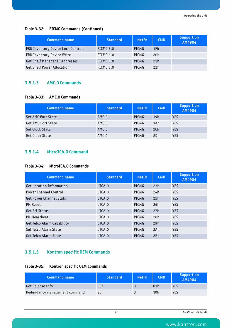
Operating the Unit
3.5.1.3 AMC.0 Commands
3.5.1.4 MicroTCA.0 Command
3.5.1.5 Kontron specific OEM Commands
FRU Inventory Device Lock Control PICMG 3.0 PICMG 1Fh
FRU Inventory Device Write PICMG 3.0 PICMG 20h
Get Shelf Manager IP Addresses PICMG 3.0 PICMG 21h
Get Shelf Power Allocation PICMG 3.0 PICMG 22h
Table 3-33: AMC.0 Commands
Command name Standard NetFn CMDSupport on
AM4904
Set AMC Port State AMC.0 PICMG 19h YES
Get AMC Port State AMC.0 PICMG 1Ah YES
Set Clock State AMC.0 PICMG 2Ch YES
Get Clock State AMC.0 PICMG 2Dh YES
Table 3-34: MicroTCA.0 Commands
Command name Standard NetFn CMDSupport on
AM4904
Get Location Information uTCA.0 PICMG 23h YES
Power Channel Control uTCA.0 PICMG 24h YES
Get Power Channel Stats uTCA.0 PICMG 25h YES
PM Reset uTCA.0 PICMG 26h YES
Get PM Status uTCA.0 PICMG 27h YES
PM Heartbeat uTCA.0 PICMG 28h YES
Get Telco Alarm Capability uTCA.0 PICMG 29h YES
Set Telco Alarm State uTCA.0 PICMG 2Ah YES
Get Telco Alarm State uTCA.0 PICMG 2Bh YES
Table 3-35: Kontron specific OEM Commands
Command name Standard NetFn CMDSupport on
AM4904
Get Release Info 30h 3 01h YES
Redundancy management command 30h 3 10h YES
Table 3-32: PICMG Commands (Continued)
Command name Standard NetFn CMDSupport on
AM4904
77 AM4904 User Guide
www.kontron.com
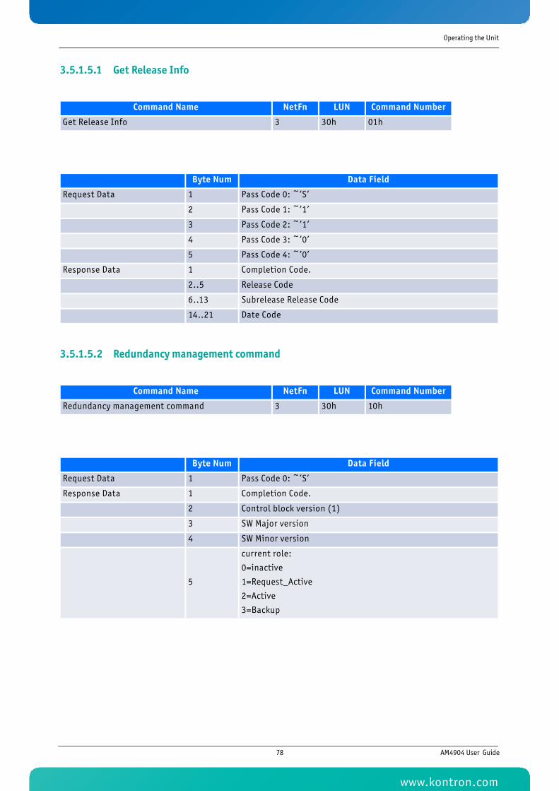
Operating the Unit
3.5.1.5.1 Get Release Info
3.5.1.5.2 Redundancy management command
Command Name NetFn LUN Command Number
Get Release Info 3 30h 01h
Byte Num Data Field
Request Data 1 Pass Code 0: ~’S’
2 Pass Code 1: ~’1’
3 Pass Code 2: ~’1’
4 Pass Code 3: ~’0’
5 Pass Code 4: ~’0’
Response Data 1 Completion Code.
2..5 Release Code
6..13 Subrelease Release Code
14..21 Date Code
Command Name NetFn LUN Command Number
Redundancy management command 3 30h 10h
Byte Num Data Field
Request Data 1 Pass Code 0: ~’S’
Response Data 1 Completion Code.
2 Control block version (1)
3 SW Major version
4 SW Minor version
5
current role:
0=inactive
1=Request_Active
2=Active
3=Backup
78 AM4904 User Guide
www.kontron.com
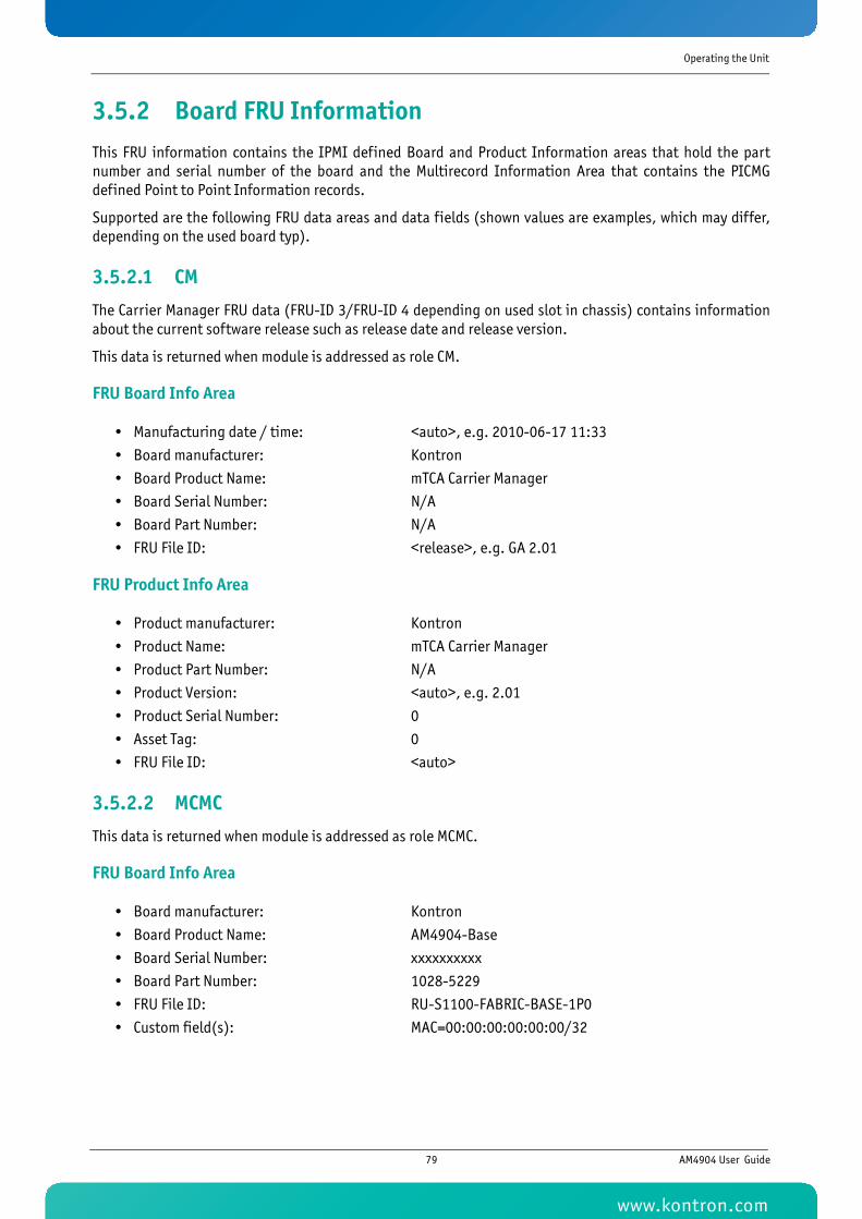
Operating the Unit
3.5.2 Board FRU InformationThis FRU information contains the IPMI defined Board and Product Information areas that hold the partnumber and serial number of the board and the Multirecord Information Area that contains the PICMGdefined Point to Point Information records.
Supported are the following FRU data areas and data fields (shown values are examples, which may differ,depending on the used board typ).
3.5.2.1 CM
The Carrier Manager FRU data (FRU-ID 3/FRU-ID 4 depending on used slot in chassis) contains informationabout the current software release such as release date and release version.
This data is returned when module is addressed as role CM.
FRU Board Info Area
• Manufacturing date / time: <auto>, e.g. 2010-06-17 11:33
• Board manufacturer: Kontron
• Board Product Name: mTCA Carrier Manager
• Board Serial Number: N/A
• Board Part Number: N/A
• FRU File ID: <release>, e.g. GA 2.01
FRU Product Info Area
• Product manufacturer: Kontron
• Product Name: mTCA Carrier Manager
• Product Part Number: N/A
• Product Version: <auto>, e.g. 2.01
• Product Serial Number: 0
• Asset Tag: 0
• FRU File ID: <auto>
3.5.2.2 MCMC
This data is returned when module is addressed as role MCMC.
FRU Board Info Area
• Board manufacturer: Kontron
• Board Product Name: AM4904-Base
• Board Serial Number: xxxxxxxxxx
• Board Part Number: 1028-5229
• FRU File ID: RU-S1100-FABRIC-BASE-1P0
• Custom field(s): MAC=00:00:00:00:00:00/32
79 AM4904 User Guide
www.kontron.com

Operating the Unit
FRU Product Info Area
• Product manufacturer: Kontron
• Product Name: AM4904-Base
• Product Part Number: 1028-5229
• Product Version: 1
• Product Serial Number: xxxxxxxxxx
• Asset Tag: 0
• FRU File ID: FRU-S1100-FABRIC-BASE-1P0
3.6 BootloaderOn the AM4904 board, the bootloader ‘u-boot‘ (universal bootloader) is used. The bootloader initializes themain components of the board like CPU, SDRAM, serial lines etc. for operation. After this, kernel and appli-cation are started from flash.
3.6.1 Power On Self TestUpon power on or system reset, the bootloader performs a set of Power On Self Tests (POST) to check theintegrity of specific components. Components where a POST is available are:
• SDRAM
• PPC405 serial line
• PPC405 I2C
• PPC405 FE
In the case that a POST fails, a POST error code is written into the postcode high byte register of the onboardCPLD. The boot process is not stopped as there are good chances the board can boot even in case of POSTerrors. The postcode high byte register is also accessible by the PM which can report error codes to a sepa-rate management instance. Thus more comprehensive diagnostic tests could be started.
The following table shows a list of available POST routines including POST error codes.
Table 3-36: POST Routines and Error Codes
Device TestPOST Numeri-cal Error Code
POST Error Code
SDRAM Data bus - walking 1 test 0x20 PCW_DLINE
SDRAM Address bus - walking 1 test 0x40 PCW_ALINE
SDRAM Memory - read/write test 0x80 PCW_MEM
PPC405 UART Serial loopback teststring 0x01 PCW_SERIAL
PPC405 I2C Bus scan for devices from I2C_ADDR_LIST 0x02 PCW_I2C
PPC405 FE Phy access 0x08 PCW_ETH1
PPC405 FE Phy loopback test using special Ethernet test frame 0x10 PCW_ETH2
KCS KCS READY signal test 0x04 KCSCTL
80 AM4904 User Guide
www.kontron.com
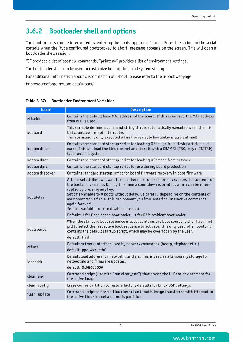
Operating the Unit
3.6.2 Bootloader shell and optionsThe boot process can be interrupted by entering the bootstopphrase "stop". Enter the string on the serialconsole when the 'type configured bootstopkey to abort' message appears on the screen. This will open abootloader shell session.
“?” provides a list of possible commands, “printenv” provides a list of environment settings.
The bootloader shell can be used to customize boot options and system startup.
For additional information about customization of u-boot, please refer to the u-boot webpage:
http://sourceforge.net/projects/u-boot/
Table 3-37: Bootloader Environment Variables
Name Description
ethaddrContains the default base MAC address of the board. If this is not set, the MAC address from VPD is used.
bootcmdThis variable def ines a command string that is automatically executed when the ini-tial countdown is not interrupted. This command is only executed when the variable bootdelay is also defined!
bootcmdflashContains the standard startup script for loading OS image from flash partition com-mand. This will load the Linux kernel and start it with a CRAMFS (TBC, maybe INITRD) type root f ile system.
bootcmdnet Contains the standard startup script for loading OS image from network
bootcmdprd Contains the standard startup script for use during board production
bootcmdrecover Contains standard startup script for board f irmware recovery in boot f irmware
bootdelay
After reset, U-Boot will wait this number of seconds before it executes the contents of the bootcmd variable. During this time a countdown is printed, which can be inter-rupted by pressing any key. Set this variable to 0 boots without delay. Be careful: depending on the contents of your bootcmd variable, this can prevent you from entering interactive commands again forever! Set this variable to -1 to disable autoboot.
Default: 3 for flash based bootloader, -1 for RAM resident bootloader
bootsource
When the standard boot sequence is used, contains the boot source, either flash, net, prd to select the respective boot sequence to activate. It is only used when bootcmd contains the default startup script, which may be overridden by the user.
default: flash
ethactDefault network interface used by network commands (bootp, tftpboot et al)
default: ppc_4xx_eth0
loadaddrDefault load address for network transfers. This is used as a temporary storage for netbooting and f irmware updates.
default: 0x08000000
clear_envCommand script (use with “run clear_env”) that erases the U-Boot environment for the active image
clear_config Erase config partition to restore factory defaults for Linux BSP settings.
flash_updateCommand script to flash a Linux kernel and rootfs image transferred with tftpboot to the active Linux kernel and rootfs partition
81 AM4904 User Guide
www.kontron.com
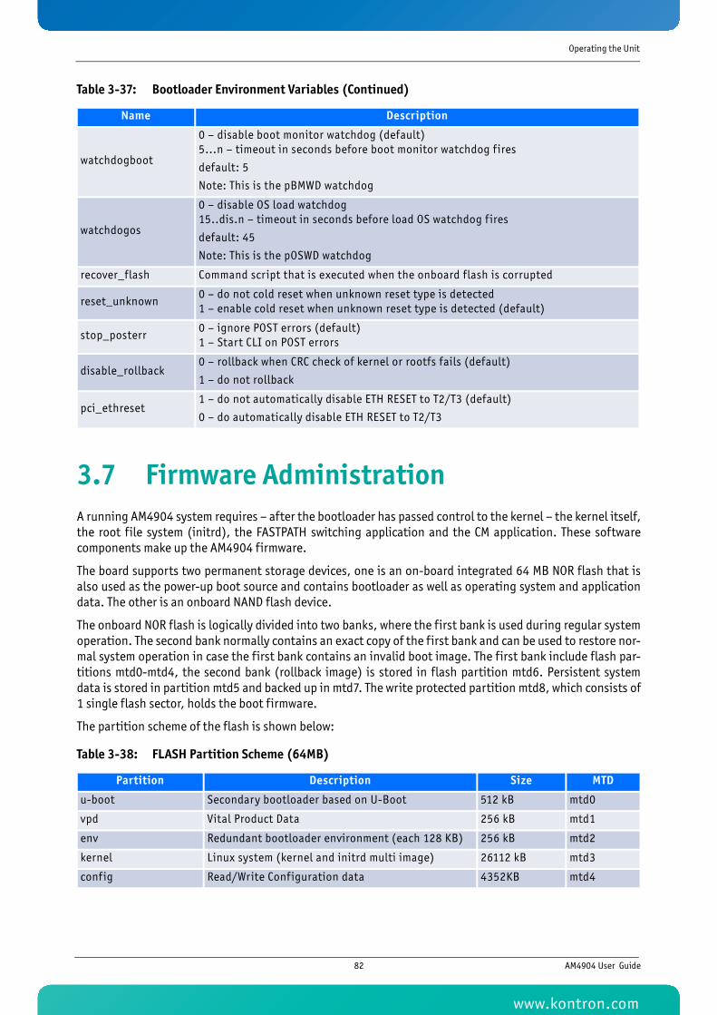
Operating the Unit
3.7 Firmware AdministrationA running AM4904 system requires – after the bootloader has passed control to the kernel – the kernel itself,the root file system (initrd), the FASTPATH switching application and the CM application. These softwarecomponents make up the AM4904 firmware.
The board supports two permanent storage devices, one is an on-board integrated 64 MB NOR flash that isalso used as the power-up boot source and contains bootloader as well as operating system and applicationdata. The other is an onboard NAND flash device.
The onboard NOR flash is logically divided into two banks, where the first bank is used during regular systemoperation. The second bank normally contains an exact copy of the first bank and can be used to restore nor-mal system operation in case the first bank contains an invalid boot image. The first bank include flash par-titions mtd0-mtd4, the second bank (rollback image) is stored in flash partition mtd6. Persistent systemdata is stored in partition mtd5 and backed up in mtd7. The write protected partition mtd8, which consists of1 single flash sector, holds the boot firmware.
The partition scheme of the flash is shown below:
watchdogboot
0 – disable boot monitor watchdog (default)5...n – timeout in seconds before boot monitor watchdog f ires
default: 5
Note: This is the pBMWD watchdog
watchdogos
0 – disable OS load watchdog15..dis.n – timeout in seconds before load OS watchdog f ires
default: 45
Note: This is the pOSWD watchdog
recover_flash Command script that is executed when the onboard flash is corrupted
reset_unknown0 – do not cold reset when unknown reset type is detected1 – enable cold reset when unknown reset type is detected (default)
stop_posterr0 – ignore POST errors (default)1 – Start CLI on POST errors
disable_rollback0 – rollback when CRC check of kernel or rootfs fails (default)
1 – do not rollback
pci_ethreset1 – do not automatically disable ETH RESET to T2/T3 (default)
0 – do automatically disable ETH RESET to T2/T3
Table 3-38: FLASH Partition Scheme (64MB)
Partition Description Size MTD
u-boot Secondary bootloader based on U-Boot 512 kB mtd0
vpd Vital Product Data 256 kB mtd1
env Redundant bootloader environment (each 128 KB) 256 kB mtd2
kernel Linux system (kernel and initrd multi image) 26112 kB mtd3
config Read/Write Configuration data 4352KB mtd4
Table 3-37: Bootloader Environment Variables (Continued)
Name Description
82 AM4904 User Guide
www.kontron.com
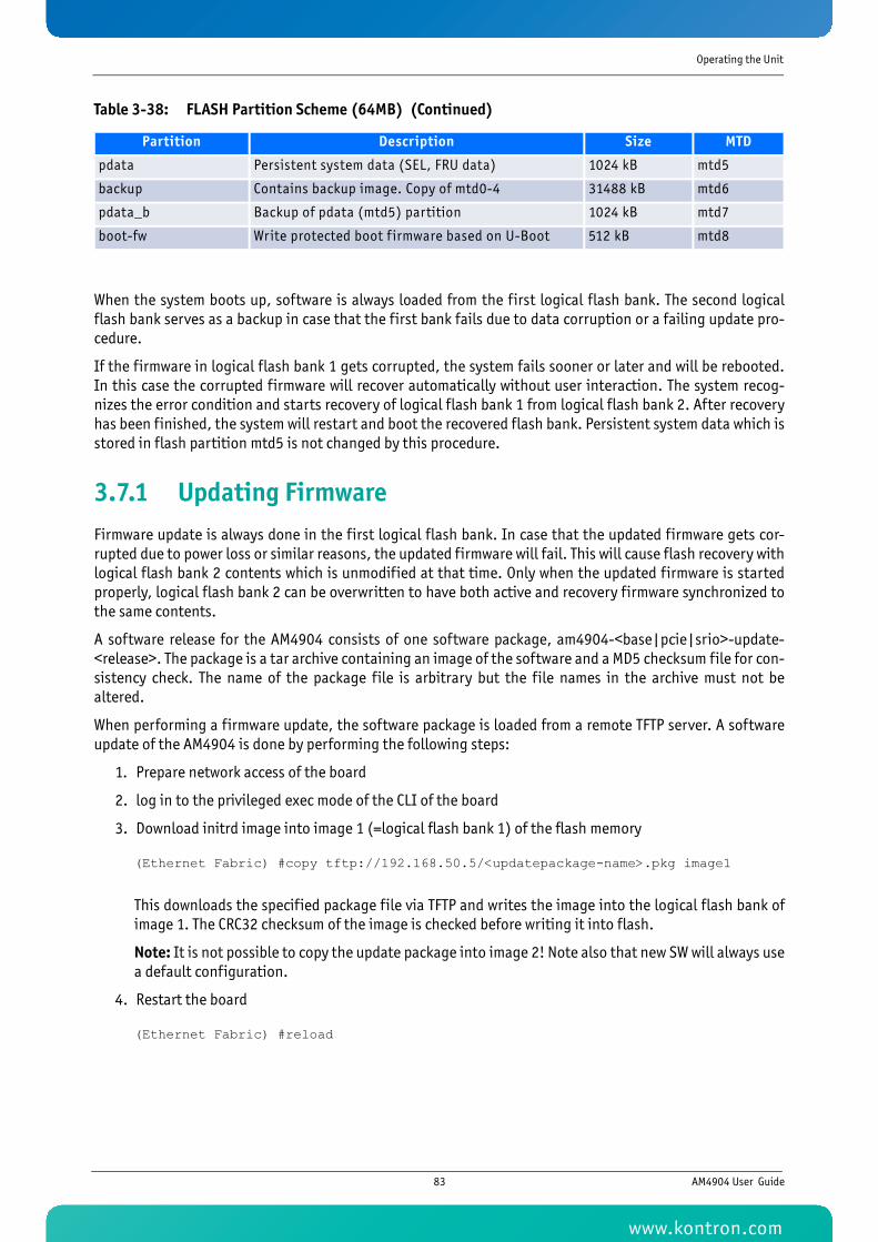
Operating the Unit
When the system boots up, software is always loaded from the first logical flash bank. The second logicalflash bank serves as a backup in case that the first bank fails due to data corruption or a failing update pro-cedure.
If the firmware in logical flash bank 1 gets corrupted, the system fails sooner or later and will be rebooted.In this case the corrupted firmware will recover automatically without user interaction. The system recog-nizes the error condition and starts recovery of logical flash bank 1 from logical flash bank 2. After recoveryhas been finished, the system will restart and boot the recovered flash bank. Persistent system data which isstored in flash partition mtd5 is not changed by this procedure.
3.7.1 Updating FirmwareFirmware update is always done in the first logical flash bank. In case that the updated firmware gets cor-rupted due to power loss or similar reasons, the updated firmware will fail. This will cause flash recovery withlogical flash bank 2 contents which is unmodified at that time. Only when the updated firmware is startedproperly, logical flash bank 2 can be overwritten to have both active and recovery firmware synchronized tothe same contents.
A software release for the AM4904 consists of one software package, am4904-<base|pcie|srio>-update-<release>. The package is a tar archive containing an image of the software and a MD5 checksum file for con-sistency check. The name of the package file is arbitrary but the file names in the archive must not bealtered.
When performing a firmware update, the software package is loaded from a remote TFTP server. A softwareupdate of the AM4904 is done by performing the following steps:
1. Prepare network access of the board
2. log in to the privileged exec mode of the CLI of the board
3. Download initrd image into image 1 (=logical flash bank 1) of the flash memory
(Ethernet Fabric) #copy tftp://192.168.50.5/<updatepackage-name>.pkg image1
This downloads the specified package file via TFTP and writes the image into the logical flash bank ofimage 1. The CRC32 checksum of the image is checked before writing it into flash.
Note: It is not possible to copy the update package into image 2! Note also that new SW will always usea default configuration.
4. Restart the board
(Ethernet Fabric) #reload
pdata Persistent system data (SEL, FRU data) 1024 kB mtd5
backup Contains backup image. Copy of mtd0-4 31488 kB mtd6
pdata_b Backup of pdata (mtd5) partition 1024 kB mtd7
boot-fw Write protected boot f irmware based on U-Boot 512 kB mtd8
Table 3-38: FLASH Partition Scheme (64MB) (Continued)
Partition Description Size MTD
83 AM4904 User Guide
www.kontron.com
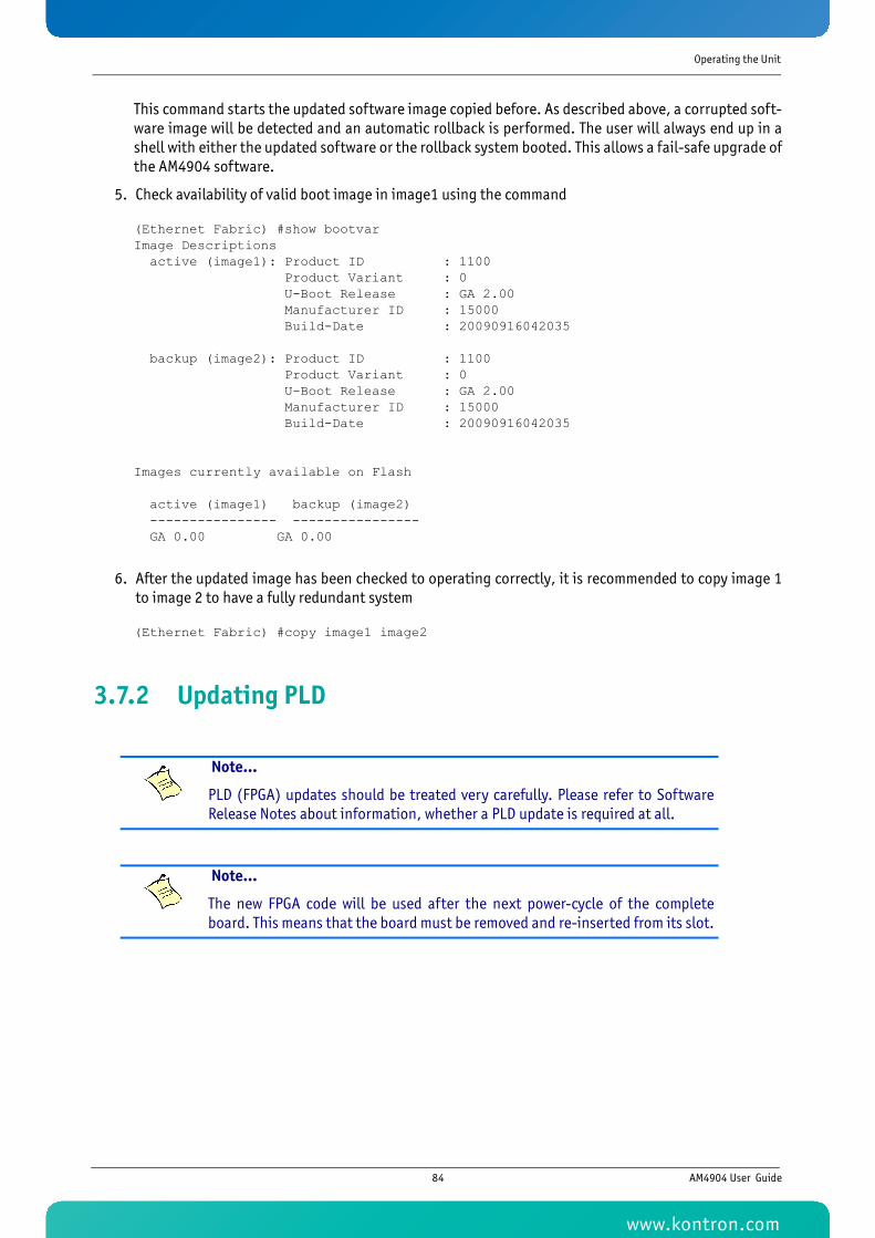
Operating the Unit
This command starts the updated software image copied before. As described above, a corrupted soft-ware image will be detected and an automatic rollback is performed. The user will always end up in ashell with either the updated software or the rollback system booted. This allows a fail-safe upgrade ofthe AM4904 software.
5. Check availability of valid boot image in image1 using the command
(Ethernet Fabric) #show bootvarImage Descriptions active (image1): Product ID : 1100 Product Variant : 0 U-Boot Release : GA 2.00 Manufacturer ID : 15000 Build-Date : 20090916042035 backup (image2): Product ID : 1100 Product Variant : 0 U-Boot Release : GA 2.00 Manufacturer ID : 15000 Build-Date : 20090916042035
Images currently available on Flash active (image1) backup (image2) ---------------- ---------------- GA 0.00 GA 0.00
6. After the updated image has been checked to operating correctly, it is recommended to copy image 1to image 2 to have a fully redundant system
(Ethernet Fabric) #copy image1 image2
3.7.2 Updating PLD
Note...
PLD (FPGA) updates should be treated very carefully. Please refer to SoftwareRelease Notes about information, whether a PLD update is required at all.
Note...
The new FPGA code will be used after the next power-cycle of the completeboard. This means that the board must be removed and re-inserted from its slot.
84 AM4904 User Guide
www.kontron.com

Operating the Unit
The onboard FPGA can be updated using the 'copy' command from the Fastpath CLI:
(Ethernet Fabric) #copy tftp://<ip_addr>/am4904-pld-update-GA-2.03.pkg image2
Mode........................................... TFTPSet Server IP.................................. 192.168.50.5Path........................................... ./Filename....................................... am4904-pld-update-GA-2.03.pkgData Type...................................... CodeDestination Filename........................... image2
Management access will be blocked for the duration of the transferAre you sure you want to start? (y/n) y Write image to flash starting...
File transfer operation completed successfully.
(Ethernet Fabric) #
85 AM4904 User Guide
www.kontron.com
85KTC5520/EATX
Chapter 4
Hardware Installation
www.kontron.com

Hardware Installation
4 Hardware InstallationThe AM4904 has been designed for easy installation. However, the following standard precautions, installa-tion procedures and general information must be observed to ensure proper installation and to precludedamage to the product, other system components, or injury to personnel.
4.1 Safety RequirementsThe following safety precautions must be observed when installing or operating the AM4904. Kontronassumes no responsibility for any damage resulting from failure to comply with these requirements.
WARNING
MCH modules require, by design, a considerable amount of force inorder to (dis)engage the module from/in the MicroTCA™ backplane con-nector. For this reason, when inserting or extracting the module, applyonly as much force as required to preclude damage to either the mod-ule’s handle or the front panel.
DO NOT push on the module handle to seat the module in the backplaneconnector. Do not use the module handle as a grip to handle the boardoutside of the chassis slot.
Use of excessive force, bending or rotation of the module handle willresult in damage to the handle or the module’s locking mechanism.Kontron disclaims all liability for damage to the module or the systemas a result of failure to comply with this warning.
ESD Sensitive Device
This AMC board contains electrostatically sensitive devices. Please observe the neces-sary precautions to avoid damage to your board:
• Discharge your clothing before touching the assembly. Tools must be dis-charged before use.
• Do not touch components, connector-pins or traces.
• If working at an anti-static workbench with professional discharging equip-ment, please do not omit to use it.
WARNING
This product has gold conductive fingers which are susceptible to con-tamination. Take care not to touch the gold conductive fingers of theAMC Card-edge connector when handling the board.
Failure to comply with the instruction above may cause damage to theboard or result in improper system operation.
86 AM4904 User Guide
www.kontron.com

Hardware Installation
4.2 Hot Swap ProceduresThe AM4904 is designed for hot swap operation. Hot swapping allows the coordinated insertion and extrac-tion of modules without disrupting other operational elements within the system.
The procedures contained in this section are also applicable for “non-operating systems” with the exceptionof indications and functions which require power to be applied.
4.2.1 Hot Swap InsertionTo insert the MCH module proceed as follows:
1. Ensure that the safety requirements indicated in section 4.1 are observed.
Caution, Laser Light!
Laser light from fiber-optic transmission cables and components can damage youreyes. The laser components plugged into the switch are Class 1 laser components.Class 1 laser is considered incapable of producing damaging radiation levels duringnormal operation or maintenance.
To avoid damaging your eyes and to continue safe operation in case of abnormal cir-cumstances:
• Never look directly into the outlets of fiber-optic transmission components or fi-ber-optic cables with unprotected eyes.
• Never allow fiber-optic transmission path to operate until all the connectionshave been made.
• Always fit protective plugs to any unused ports of the switch.
WARNING
Failure to comply with the instruction above may cause damage to theboard or result in improper system operation.
87 AM4904 User Guide
www.kontron.com
Hardware Installation
2. Ensure that the module is properly configured for operation in accordance with the application require-ments before installation.
3. Ensure that the module handle is in the “Unlocked” position.
4. Using the front panel as a grip, carefully insert the module into the slot designated by the applicationrequirements until it makes contact with the backplane connector.
5. Apply pressure to the front panel until the module is properly seated in the backplane connector. Thismay require a considerable amount of force. Apply pressure only to the front panel, not the modulehandle. During seating in the connector, there is a noticeable “snapping” of the board into the connec-tor. When the board is seated it should be flush with the system front panel.
In the case of a running system, the following occurs:
• The BLUE HS LED turns on. When the module is seated, the module management power is applied and the BLUE HS LED turnson. (No payload power is applied at this time).
• Connect all external interfacing cables to the module as required and ensure that they are properlysecured.
• Push the module handle in the “Locked” position. When the module handle is in the “Locked” po-sition, the module is locked and the hot swap switch is actuated.
In the case of a running system, the following occurs:
• The BLUE HS LED turns off.The power module now enables the payload power for the MCH.
• The MCH module is now operating.
4.2.2 Hot Swap ExtractionTo extract the MCH module proceed as follows:
1. Ensure that the safety requirements indicated in section 4.1 are observed.
2. Pull the module handle in the “Hot Swap” position.
When the module handle is in the “Hot Swap” position, the extraction process of the module is initiated andthe following occurs:
• The BLUE HS LED displays short blinks. When the power module IPMI controller receives the handleopened event, it sends a command to the MCMC with a request to perform short blinks of the BLUEHS LED. This indicates that the MCH is waiting to be deactivated. Once the MCH receives the permission to continue the deactivation, all used ports are disabled.
• The BLUE HS LED turns on. The Intelligent Platform Management Controller on the power module disables the module's pay-load power and the BLUE HS LED is turned on. Now the module is ready to be safely extracted.
WARNING
Care must be taken when applying the procedures below to ensure thatneither the AM4904 nor other system boards are physically damaged bythe application of these procedures.
88 AM4904 User Guide
www.kontron.com

Hardware Installation
3. Pull the module handle in the “Unlocked” position.
4. Disconnect any interfacing cables that may be connected to the module.
5. Disengage the module from the backplane connector by pulling on the module handle. On four-tongue-MCHs with fabric DEFG infrastructure, an additional extraction grip is available because of the en-hanced extraction force.
6. Using the front panel as a grip, remove the module from the chassis.
7. Dispose of the module as required.
WARNING
The Blue LED has to be solid on before removing the module. If the systemdoes not support Hot Swap, it has to be assured that the 12V payloadpower is switched off.
Removing the module with 12V payload power still enabled may damage it.
89 AM4904 User Guide
www.kontron.com

90KTC5520/EATX
Chapter 5
Power Considerations
www.kontron.com

Power Considerations
5 Power Considerations
5.1 AM4904 Input Voltage RangesThe AM4904 board has been designed for optimal power input and distribution. Still it is necessary toobserve certain criteria essential for application stability and reliability.
The AM4904 requires two power sources, the module management power (nominal: 3.3V DC) and payloadpower (nominal: 12V DC).
The following table specifies the ranges for the different input power voltages within which the board isfunctional. The AM4904 is not guaranteed to function if the board is not operated within the operatingrange.
5.2 Carrier Power Requirements
5.2.1 Payload PowerPayload power is the power provided to the module from the backplane for the main function of the module.
It is recommended that Payload Power voltage provided by the system is at the higher end of the specifiedvoltage range under no load conditions so that under high load conditions the current will be as low as pos-sible.
The payload power voltage shall be at least 10.8 V and not more than 13.8 V at the module contacts duringnormal conditions under all loads (see “DC Operational Input Voltage Ranges” on page 91).
The bandwidth-limited periodic noise due to switching power supplies or any other source shall not exceed200 mV peak to peak.
Table 5-1: DC Operational Input Voltage Ranges
Input Supply VoltageAbsolute Range
(according AMC.0)Operating Range
(backplane requirements)
Payload Power
(nominal: 12V DC)10.0 V min. to 14 V max. 10.8 V min. to 13.2 V max.
Module Management Power
(nominal: 3.3V DC)3.0 V min. to 3.6 V max. 3.135 V min. to 3.465 V max.
WARNING
The AM4904 must not be operated beyond the absolute range indi-cated in the table above. Failure to comply with the above may resultin damage to the board.
91 AM4904 User Guide
www.kontron.com
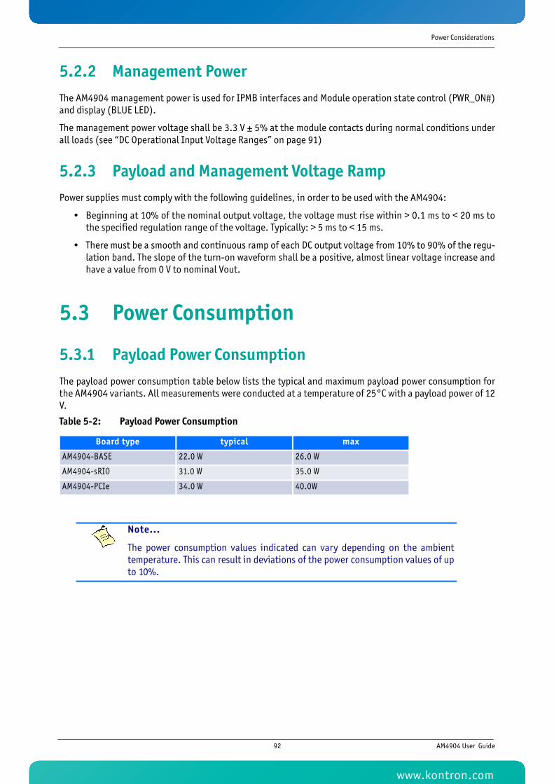
Power Considerations
5.2.2 Management PowerThe AM4904 management power is used for IPMB interfaces and Module operation state control (PWR_ON#)and display (BLUE LED).
The management power voltage shall be 3.3 V ± 5% at the module contacts during normal conditions underall loads (see “DC Operational Input Voltage Ranges” on page 91)
5.2.3 Payload and Management Voltage RampPower supplies must comply with the following guidelines, in order to be used with the AM4904:
• Beginning at 10% of the nominal output voltage, the voltage must rise within > 0.1 ms to < 20 ms tothe specified regulation range of the voltage. Typically: > 5 ms to < 15 ms.
• There must be a smooth and continuous ramp of each DC output voltage from 10% to 90% of the regu-lation band. The slope of the turn-on waveform shall be a positive, almost linear voltage increase andhave a value from 0 V to nominal Vout.
5.3 Power Consumption
5.3.1 Payload Power ConsumptionThe payload power consumption table below lists the typical and maximum payload power consumption forthe AM4904 variants. All measurements were conducted at a temperature of 25°C with a payload power of 12V.
Table 5-2: Payload Power Consumption
Board type typical max
AM4904-BASE 22.0 W 26.0 W
AM4904-sRIO 31.0 W 35.0 W
AM4904-PCIe 34.0 W 40.0W
Note...
The power consumption values indicated can vary depending on the ambienttemperature. This can result in deviations of the power consumption values of upto 10%.
92 AM4904 User Guide
www.kontron.com

Power Considerations
5.3.2 Management Power ConsumptionThe maximum current is below 100mA. Management Power is 330 mW max.
5.4 Payload Start-Up Current of the AM4904The payload start-up current of the AM4904 during the first 2-3 seconds after the payload power has beenapplied is 1.8 A.
For further information on the start-up current, please contact Kontron.
93 AM4904 User Guide
www.kontron.com

Chapter 6
Thermal Considerations
www.kontron.com
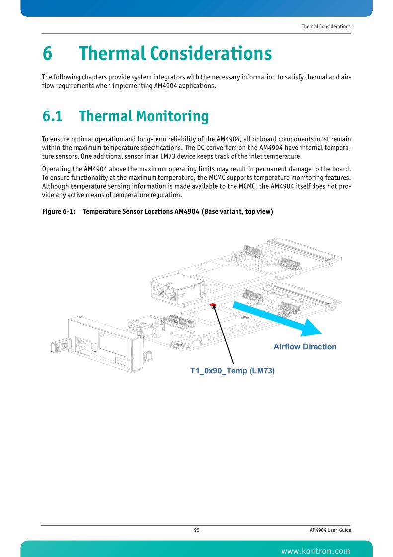
Thermal Considerations
6 Thermal ConsiderationsThe following chapters provide system integrators with the necessary information to satisfy thermal and air-flow requirements when implementing AM4904 applications.
6.1 Thermal MonitoringTo ensure optimal operation and long-term reliability of the AM4904, all onboard components must remainwithin the maximum temperature specifications. The DC converters on the AM4904 have internal tempera-ture sensors. One additional sensor in an LM73 device keeps track of the inlet temperature.
Operating the AM4904 above the maximum operating limits may result in permanent damage to the board.To ensure functionality at the maximum temperature, the MCMC supports temperature monitoring features.Although temperature sensing information is made available to the MCMC, the AM4904 itself does not pro-vide any active means of temperature regulation.
Figure 6-1: Temperature Sensor Locations AM4904 (Base variant, top view)
T1_0x90_Temp (LM73)
Airflow Direction
95 AM4904 User Guide
www.kontron.com
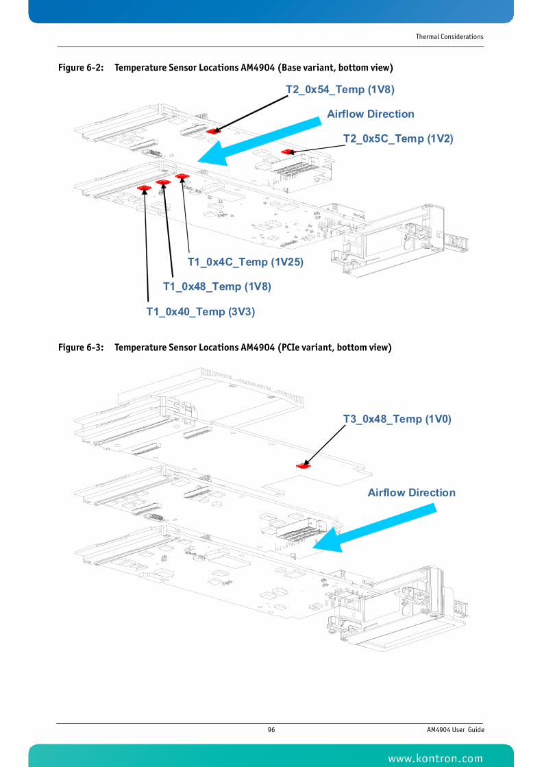
Thermal Considerations
Figure 6-2: Temperature Sensor Locations AM4904 (Base variant, bottom view)
Figure 6-3: Temperature Sensor Locations AM4904 (PCIe variant, bottom view)
T1_0x4C_Temp (1V25)
T1_0x48_Temp (1V8)
T1_0x40_Temp (3V3)
Airflow Direction
T2_0x5C_Temp (1V2)
T2_0x54_Temp (1V8)
Airflow Direction
T3_0x48_Temp (1V0)
96 AM4904 User Guide
www.kontron.com
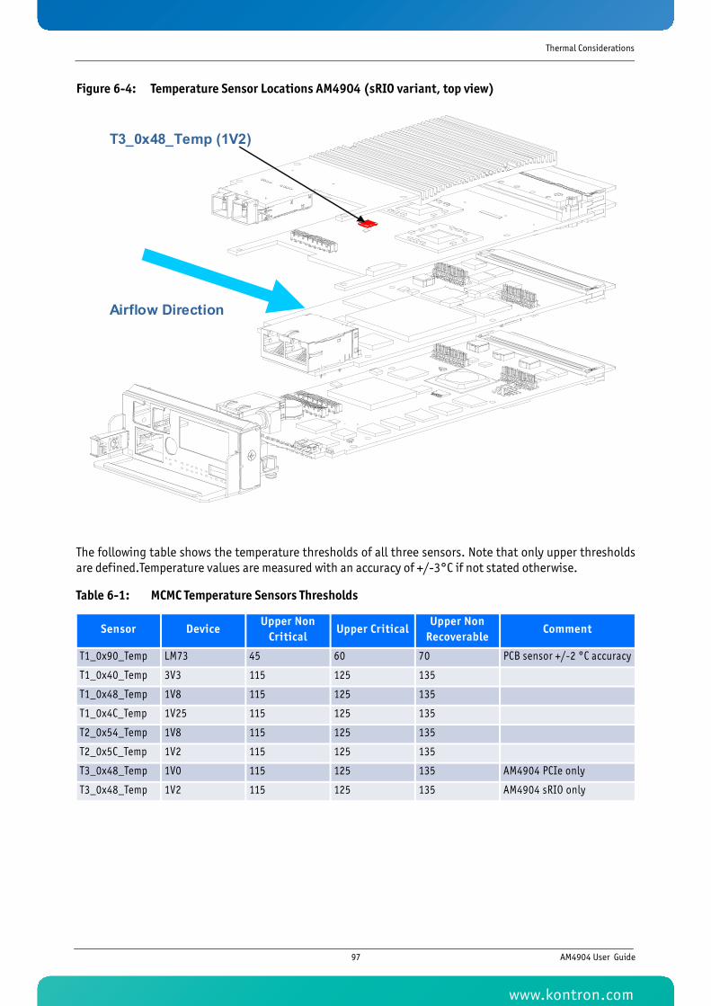
Thermal Considerations
Figure 6-4: Temperature Sensor Locations AM4904 (sRIO variant, top view)
The following table shows the temperature thresholds of all three sensors. Note that only upper thresholdsare defined.Temperature values are measured with an accuracy of +/-3°C if not stated otherwise.
Table 6-1: MCMC Temperature Sensors Thresholds
Sensor DeviceUpper Non
CriticalUpper Critical
Upper Non Recoverable
Comment
T1_0x90_Temp LM73 45 60 70 PCB sensor +/-2 °C accuracy
T1_0x40_Temp 3V3 115 125 135
T1_0x48_Temp 1V8 115 125 135
T1_0x4C_Temp 1V25 115 125 135
T2_0x54_Temp 1V8 115 125 135
T2_0x5C_Temp 1V2 115 125 135
T3_0x48_Temp 1V0 115 125 135 AM4904 PCIe only
T3_0x48_Temp 1V2 115 125 135 AM4904 sRIO only
T3_0x48_Temp (1V2)
Airflow Direction
97 AM4904 User Guide
www.kontron.com
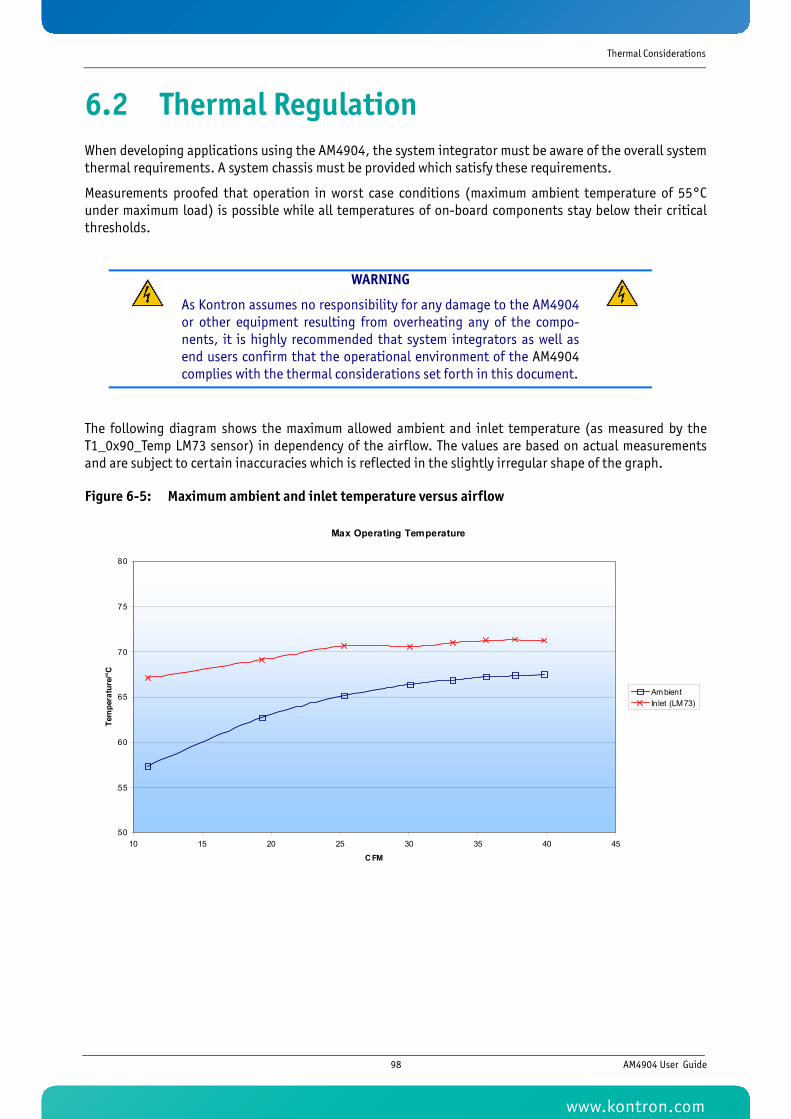
Thermal Considerations
6.2 Thermal RegulationWhen developing applications using the AM4904, the system integrator must be aware of the overall systemthermal requirements. A system chassis must be provided which satisfy these requirements.
Measurements proofed that operation in worst case conditions (maximum ambient temperature of 55°Cunder maximum load) is possible while all temperatures of on-board components stay below their criticalthresholds.
The following diagram shows the maximum allowed ambient and inlet temperature (as measured by theT1_0x90_Temp LM73 sensor) in dependency of the airflow. The values are based on actual measurementsand are subject to certain inaccuracies which is reflected in the slightly irregular shape of the graph.
Figure 6-5: Maximum ambient and inlet temperature versus airflow
WARNING
As Kontron assumes no responsibility for any damage to the AM4904or other equipment resulting from overheating any of the compo-nents, it is highly recommended that system integrators as well asend users confirm that the operational environment of the AM4904complies with the thermal considerations set forth in this document.
Max Operating Temperature
50
55
60
65
70
75
80
10 15 20 25 30 35 40 45
CFM
Tem
pera
ture
/°C
AmbientInlet (LM73)
98 AM4904 User Guide
www.kontron.com
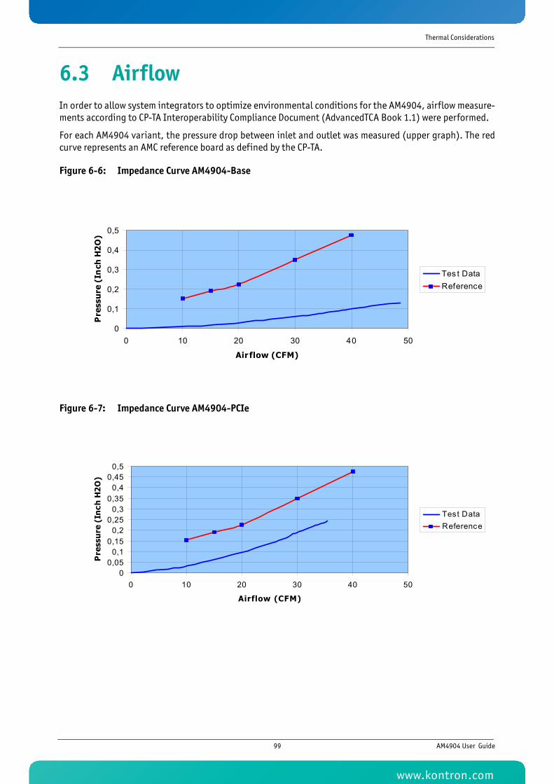
Thermal Considerations
6.3 AirflowIn order to allow system integrators to optimize environmental conditions for the AM4904, airflow measure-ments according to CP-TA Interoperability Compliance Document (AdvancedTCA Book 1.1) were performed.
For each AM4904 variant, the pressure drop between inlet and outlet was measured (upper graph). The redcurve represents an AMC reference board as defined by the CP-TA.
Figure 6-6: Impedance Curve AM4904-Base
Figure 6-7: Impedance Curve AM4904-PCIe
0
0,1
0,2
0,3
0,4
0,5
0 10 20 30 40 50
Air flow (CFM)
Pre
ssu
re (
Inch
H2
O)
Tes t DataReference
00,05
0,10,15
0,20,25
0,30,35
0,40,45
0,5
0 10 20 30 40 50
Airflow (CFM)
Pre
ssu
re (
Inch
H2
O)
Test DataReference
99 AM4904 User Guide
www.kontron.com
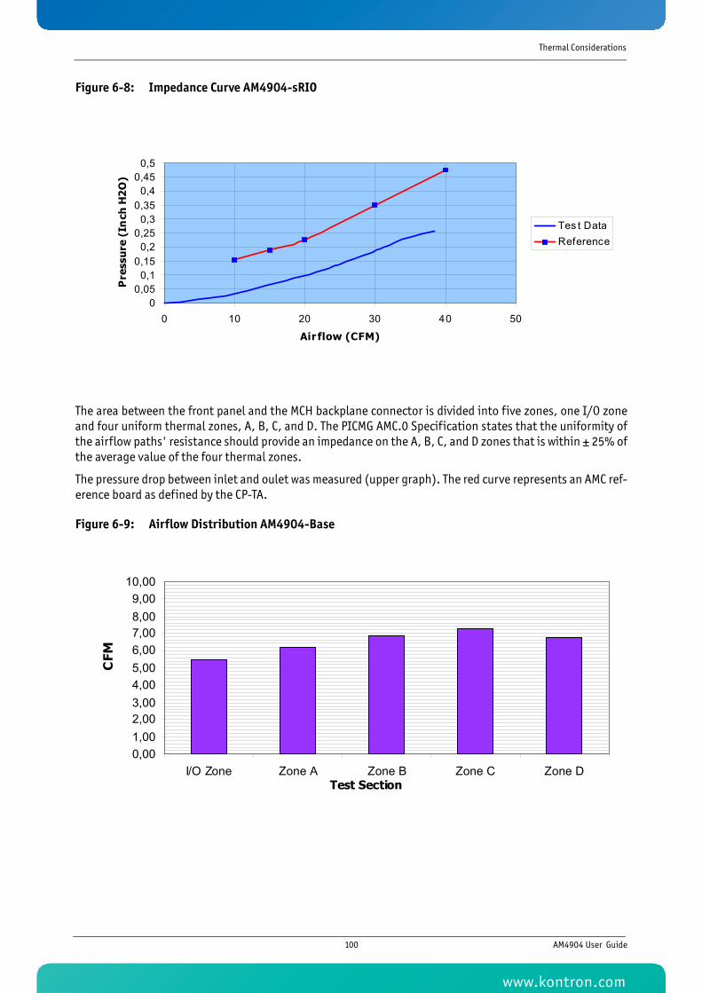
Thermal Considerations
Figure 6-8: Impedance Curve AM4904-sRIO
The area between the front panel and the MCH backplane connector is divided into five zones, one I/O zoneand four uniform thermal zones, A, B, C, and D. The PICMG AMC.0 Specification states that the uniformity ofthe airflow paths' resistance should provide an impedance on the A, B, C, and D zones that is within ± 25% ofthe average value of the four thermal zones.
The pressure drop between inlet and oulet was measured (upper graph). The red curve represents an AMC ref-erence board as defined by the CP-TA.
Figure 6-9: Airflow Distribution AM4904-Base
00,05
0,10,15
0,20,25
0,30,35
0,40,45
0,5
0 10 20 30 40 50
Air flow (CFM)
Pre
ssu
re (
Inch
H2
O)
Tes t DataReference
0,001,002,003,004,005,006,007,008,009,00
10,00
I/O Zone Zone A Zone B Zone C Zone DTest Section
CFM
100 AM4904 User Guide
www.kontron.com
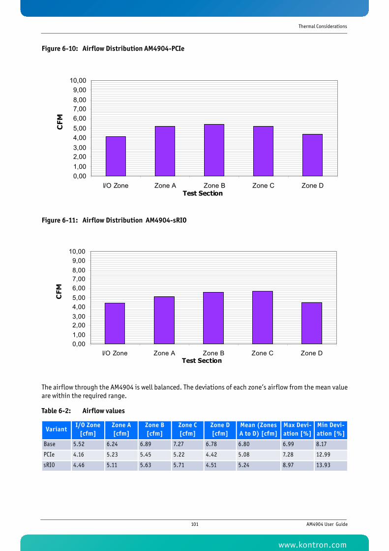
Thermal Considerations
Figure 6-10: Airflow Distribution AM4904-PCIe
Figure 6-11: Airflow Distribution AM4904-sRIO
The airflow through the AM4904 is well balanced. The deviations of each zone’s airflow from the mean valueare within the required range.
Table 6-2: Airflow values
VariantI/O Zone
[cfm]Zone A [cfm]
Zone B [cfm]
Zone C [cfm]
Zone D [cfm]
Mean (Zones A to D) [cfm]
Max Devi-ation [%]
Min Devi-ation [%]
Base 5.52 6.24 6.89 7.27 6.78 6.80 6.99 8.17
PCIe 4.16 5.23 5.45 5.22 4.42 5.08 7.28 12.99
sRIO 4.46 5.11 5.63 5.71 4.51 5.24 8.97 13.93
0,001,002,003,004,005,006,007,008,009,00
10,00
I/O Zone Zone A Zone B Zone C Zone DTest Section
CFM
0,001,002,003,004,005,006,007,008,009,00
10,00
I/O Zone Zone A Zone B Zone C Zone DTest Section
CFM
101 AM4904 User Guide
www.kontron.com
1
Appendix A
CM Configuration Options
www.kontron.com
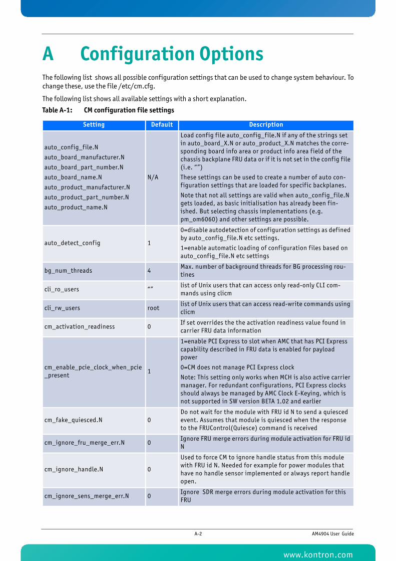
A Configuration OptionsThe following list shows all possible configuration settings that can be used to change system behaviour. Tochange these, use the file /etc/cm.cfg.
The following list shows all available settings with a short explanation.
Table A-1: CM configuration file settings
Setting Default Description
auto_config_file.N
auto_board_manufacturer.N
auto_board_part_number.N
auto_board_name.N
auto_product_manufacturer.N
auto_product_part_number.N
auto_product_name.N
N/A
Load config f ile auto_config_f ile.N if any of the strings set in auto_board_X.N or auto_product_X.N matches the corre-sponding board info area or product info area f ield of the chassis backplane FRU data or if it is not set in the config f ile (i.e. “”)
These settings can be used to create a number of auto con-f iguration settings that are loaded for specif ic backplanes.
Note that not all settings are valid when auto_config_file.N gets loaded, as basic initialisation has already been f in-ished. But selecting chassis implementations (e.g. pm_om6060) and other settings are possible.
auto_detect_config 1
0=disable autodetection of configuration settings as def ined by auto_config_file.N etc settings.
1=enable automatic loading of configuration f iles based on auto_config_file.N etc settings
bg_num_threads 4Max. number of background threads for BG processing rou-tines
cli_ro_users “”list of Unix users that can access only read-only CLI com-mands using clicm
cli_rw_users rootlist of Unix users that can access read-write commands using clicm
cm_activation_readiness 0If set overrides the the activation readiness value found in carrier FRU data information
cm_enable_pcie_clock_when_pcie_present
1
1=enable PCI Express to slot when AMC that has PCI Express capability described in FRU data is enabled for payload power
0=CM does not manage PCI Express clock
Note: This setting only works when MCH is also active carrier manager. For redundant configurations, PCI Express clocks should always be managed by AMC Clock E-Keying, which is not supported in SW version BETA 1.02 and earlier
cm_fake_quiesced.N 0Do not wait for the module with FRU id N to send a quiesced event. Assumes that module is quiesced when the response to the FRUControl(Quiesce) command is received
cm_ignore_fru_merge_err.N 0Ignore FRU merge errors during module activation for FRU id N
cm_ignore_handle.N 0
Used to force CM to ignore handle status from this module with FRU id N. Needed for example for power modules that have no handle sensor implemented or always report handle open.
cm_ignore_sens_merge_err.N 0Ignore SDR merge errors during module activation for this FRU
A-2 AM4904 User Guide
www.kontron.com
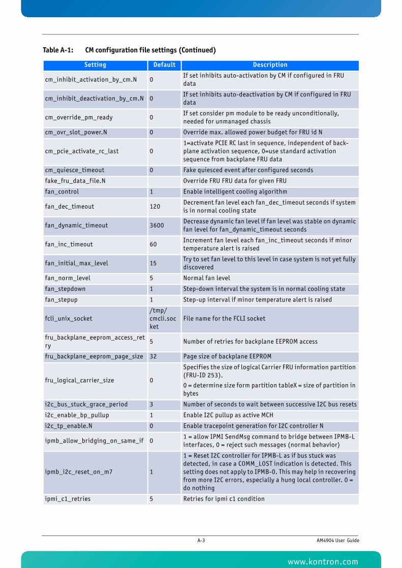
cm_inhibit_activation_by_cm.N 0If set inhibits auto-activation by CM if configured in FRU data
cm_inhibit_deactivation_by_cm.N 0If set inhibits auto-deactivation by CM if configured in FRU data
cm_override_pm_ready 0If set consider pm module to be ready unconditionally, needed for unmanaged chassis
cm_ovr_slot_power.N 0 Override max. allowed power budget for FRU id N
cm_pcie_activate_rc_last 01=activate PCIE RC last in sequence, independent of back-plane activation sequence, 0=use standard activation sequence from backplane FRU data
cm_quiesce_timeout 0 Fake quiesced event after configured seconds
fake_fru_data_file.N Override FRU FRU data for given FRU
fan_control 1 Enable intelligent cooling algorithm
fan_dec_timeout 120Decrement fan level each fan_dec_timeout seconds if system is in normal cooling state
fan_dynamic_timeout 3600Decrease dynamic fan level if fan level was stable on dynamic fan level for fan_dynamic_timeout seconds
fan_inc_timeout 60Increment fan level each fan_inc_timeout seconds if minor temperature alert is raised
fan_initial_max_level 15Try to set fan level to this level in case system is not yet fully discovered
fan_norm_level 5 Normal fan level
fan_stepdown 1 Step-down interval the system is in normal cooling state
fan_stepup 1 Step-up interval if minor temperature alert is raised
fcli_unix_socket/tmp/cmcli.socket
File name for the FCLI socket
fru_backplane_eeprom_access_retry
5 Number of retries for backplane EEPROM access
fru_backplane_eeprom_page_size 32 Page size of backplane EEPROM
fru_logical_carrier_size 0
Specif ies the size of logical Carrier FRU information partition (FRU-ID 253).
0 = determine size form partition tableX = size of partition in bytes
i2c_bus_stuck_grace_period 3 Number of seconds to wait between successive I2C bus resets
i2c_enable_bp_pullup 1 Enable I2C pullup as active MCH
i2c_tp_enable.N 0 Enable tracepoint generation for I2C controller N
ipmb_allow_bridging_on_same_if 01 = allow IPMI SendMsg command to bridge between IPMB-L interfaces, 0 = reject such messages (normal behavior)
ipmb_i2c_reset_on_m7 1
1 = Reset I2C controller for IPMB-L as if bus stuck was detected, in case a COMM_LOST indication is detected. This setting does not apply to IPMB-0. This may help in recovering from more I2C errors, especially a hung local controller. 0 = do nothing
ipmi_c1_retries 5 Retries for ipmi c1 condition
Table A-1: CM configuration file settings (Continued)
Setting Default Description
A-3 AM4904 User Guide
www.kontron.com
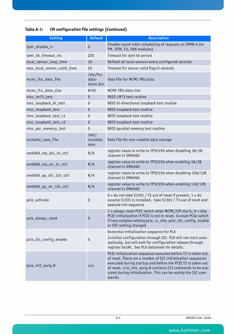
ipmi_disable_rr 0Disable round robin scheduling of requests on IPMB-0 (to PM, OEM, CU, FAN modules)
ipmi_t6_timeout_ms 220 Timeout for ipmi t6 period
local_sensor_loop_time 10 Refresh all local sensors every configured seconds
max_local_sensor_valid_time 20 Timeout for sensor valid flag in seconds
mcmc_fru_data_file/etc/fru-data-mcmc.bin
Data f ile for MCMC FRU data
mcmc_fru_data_size 8192 MCMC FRU data size
nios_lm73_test 0 NIOS LM73 test routine
nios_loopback_bi_test 0 NIOS bi-directional loopback test routine
nios_loopback_test 0 NIOS loopback test routine
nios_loopback_test_c1 0 NIOS loopback test routine
nios_loopback_test_c2 0 NIOS loopback test routine
nios_par_memory_test 0 NIOS parallel memory test routine
nvctable_save_file/etc/nvctable.save
Data f ile for non-volatile data storage
om6060_mp_dis_3v_ctrl N/Aregister value to write to TPS2359 when disabling 3A/3B channel in OM6060
om6060_mp_en_3v_ctrl N/Aregister value to write to TPS2359 when enabling 3A/3B channel in OM6060
om6060_pp_dis_12v_ctrl N/Aregister value to write to TPS2359 when disabling 12A/12B channel in OM6060
om6060_pp_en_12v_ctrl N/Aregister value to write to TPS2359 when enabling 12A/12B channel in OM6060
pcie_activate 00 = do not take S1301 / T3 out of reset if present, 1 = do assume S1301 is installed, take S1301 / T3 out of reset and execute init sequence
pcie_always_reset 0
1 = always reset PCIE switch when MCMC/CM starts, 0 = skip PCIE initialization if PCIE is not in reset, 2=reset PCIe switch if root complex setting pcie_rc_site, pcie_i2c_config_enable or SSC setting changed
pcie_i2c_config_enable 0
0=normal initialization sequence for PLX
1=initial configuration through I2C. PLX will not start auto-matically, but will wait for configuration release through register 0x3AC. See PLX datasheet for details.
pcie_init_early.N n/a
PCIE initialization sequence executed before T3 is taken out of reset. There are a number of I2C initialization sequences executed during startup and before the PCIE T3 is taken out of reset. srio_init_early.N contains CLI commands to be exe-cuted during initialization. This can be mainly the I2C com-mands.
Table A-1: CM configuration file settings (Continued)
Setting Default Description
A-4 AM4904 User Guide
www.kontron.com
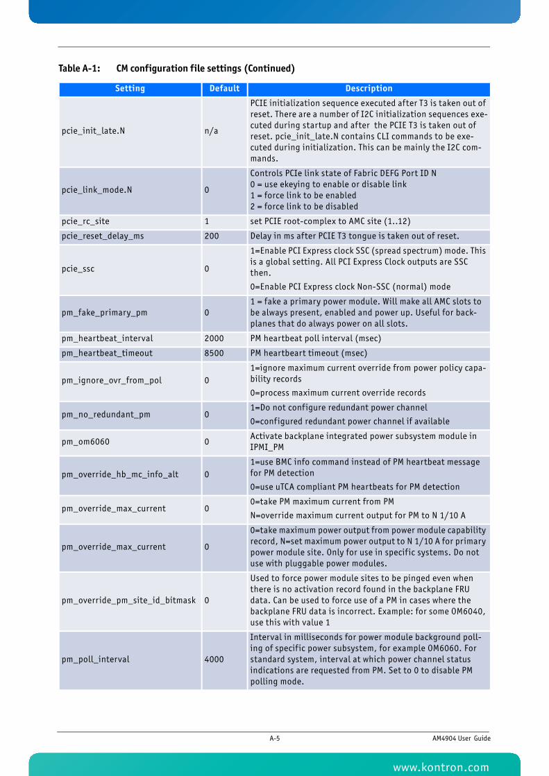
pcie_init_late.N n/a
PCIE initialization sequence executed after T3 is taken out of reset. There are a number of I2C initialization sequences exe-cuted during startup and after the PCIE T3 is taken out of reset. pcie_init_late.N contains CLI commands to be exe-cuted during initialization. This can be mainly the I2C com-mands.
pcie_link_mode.N 0
Controls PCIe link state of Fabric DEFG Port ID N0 = use ekeying to enable or disable link1 = force link to be enabled2 = force link to be disabled
pcie_rc_site 1 set PCIE root-complex to AMC site (1..12)
pcie_reset_delay_ms 200 Delay in ms after PCIE T3 tongue is taken out of reset.
pcie_ssc 0
1=Enable PCI Express clock SSC (spread spectrum) mode. This is a global setting. All PCI Express Clock outputs are SSC then.
0=Enable PCI Express clock Non-SSC (normal) mode
pm_fake_primary_pm 01 = fake a primary power module. Will make all AMC slots to be always present, enabled and power up. Useful for back-planes that do always power on all slots.
pm_heartbeat_interval 2000 PM heartbeat poll interval (msec)
pm_heartbeat_timeout 8500 PM heartbeart timeout (msec)
pm_ignore_ovr_from_pol 01=ignore maximum current override from power policy capa-bility records
0=process maximum current override records
pm_no_redundant_pm 01=Do not configure redundant power channel
0=configured redundant power channel if available
pm_om6060 0Activate backplane integrated power subsystem module in IPMI_PM
pm_override_hb_mc_info_alt 01=use BMC info command instead of PM heartbeat message for PM detection
0=use uTCA compliant PM heartbeats for PM detection
pm_override_max_current 00=take PM maximum current from PM
N=override maximum current output for PM to N 1/10 A
pm_override_max_current 0
0=take maximum power output from power module capability record, N=set maximum power output to N 1/10 A for primary power module site. Only for use in specif ic systems. Do not use with pluggable power modules.
pm_override_pm_site_id_bitmask 0
Used to force power module sites to be pinged even when there is no activation record found in the backplane FRU data. Can be used to force use of a PM in cases where the backplane FRU data is incorrect. Example: for some OM6040, use this with value 1
pm_poll_interval 4000
Interval in milliseconds for power module background poll-ing of specif ic power subsystem, for example OM6060. For standard system, interval at which power channel status indications are requested from PM. Set to 0 to disable PM polling mode.
Table A-1: CM configuration file settings (Continued)
Setting Default Description
A-5 AM4904 User Guide
www.kontron.com
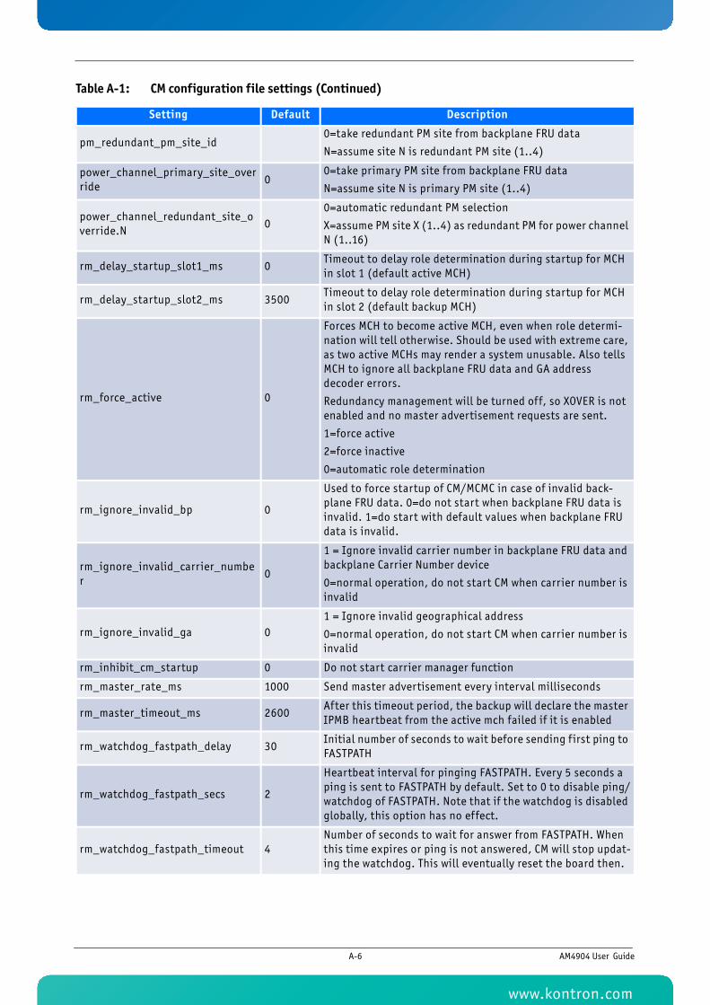
pm_redundant_pm_site_id0=take redundant PM site from backplane FRU data
N=assume site N is redundant PM site (1..4)
power_channel_primary_site_override
00=take primary PM site from backplane FRU data
N=assume site N is primary PM site (1..4)
power_channel_redundant_site_override.N
00=automatic redundant PM selection
X=assume PM site X (1..4) as redundant PM for power channel N (1..16)
rm_delay_startup_slot1_ms 0Timeout to delay role determination during startup for MCH in slot 1 (default active MCH)
rm_delay_startup_slot2_ms 3500Timeout to delay role determination during startup for MCH in slot 2 (default backup MCH)
rm_force_active 0
Forces MCH to become active MCH, even when role determi-nation will tell otherwise. Should be used with extreme care, as two active MCHs may render a system unusable. Also tells MCH to ignore all backplane FRU data and GA address decoder errors.
Redundancy management will be turned off, so XOVER is not enabled and no master advertisement requests are sent.
1=force active
2=force inactive
0=automatic role determination
rm_ignore_invalid_bp 0
Used to force startup of CM/MCMC in case of invalid back-plane FRU data. 0=do not start when backplane FRU data is invalid. 1=do start with default values when backplane FRU data is invalid.
rm_ignore_invalid_carrier_number
0
1 = Ignore invalid carrier number in backplane FRU data and backplane Carrier Number device
0=normal operation, do not start CM when carrier number is invalid
rm_ignore_invalid_ga 01 = Ignore invalid geographical address
0=normal operation, do not start CM when carrier number is invalid
rm_inhibit_cm_startup 0 Do not start carrier manager function
rm_master_rate_ms 1000 Send master advertisement every interval milliseconds
rm_master_timeout_ms 2600After this timeout period, the backup will declare the master IPMB heartbeat from the active mch failed if it is enabled
rm_watchdog_fastpath_delay 30Initial number of seconds to wait before sending f irst ping to FASTPATH
rm_watchdog_fastpath_secs 2
Heartbeat interval for pinging FASTPATH. Every 5 seconds a ping is sent to FASTPATH by default. Set to 0 to disable ping/watchdog of FASTPATH. Note that if the watchdog is disabled globally, this option has no effect.
rm_watchdog_fastpath_timeout 4Number of seconds to wait for answer from FASTPATH. When this time expires or ping is not answered, CM will stop updat-ing the watchdog. This will eventually reset the board then.
Table A-1: CM configuration file settings (Continued)
Setting Default Description
A-6 AM4904 User Guide
www.kontron.com
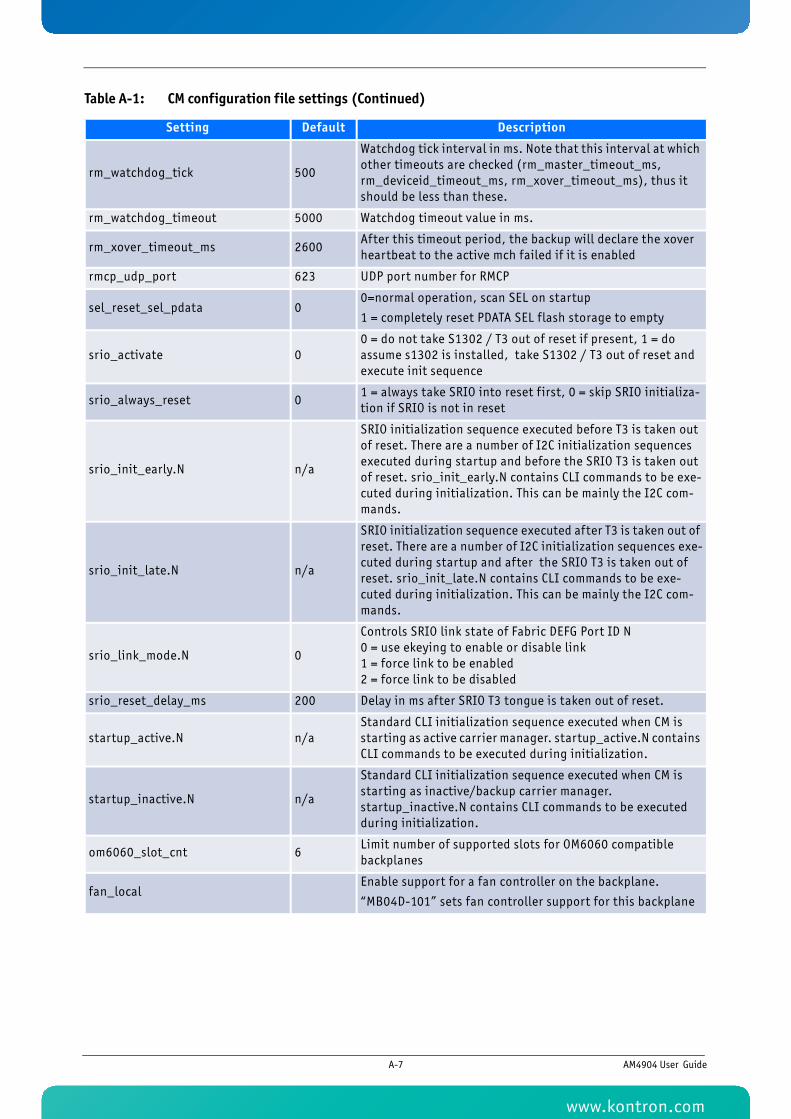
rm_watchdog_tick 500
Watchdog tick interval in ms. Note that this interval at which other timeouts are checked (rm_master_timeout_ms, rm_deviceid_timeout_ms, rm_xover_timeout_ms), thus it should be less than these.
rm_watchdog_timeout 5000 Watchdog timeout value in ms.
rm_xover_timeout_ms 2600After this timeout period, the backup will declare the xover heartbeat to the active mch failed if it is enabled
rmcp_udp_port 623 UDP port number for RMCP
sel_reset_sel_pdata 00=normal operation, scan SEL on startup
1 = completely reset PDATA SEL flash storage to empty
srio_activate 00 = do not take S1302 / T3 out of reset if present, 1 = do assume s1302 is installed, take S1302 / T3 out of reset and execute init sequence
srio_always_reset 01 = always take SRIO into reset f irst, 0 = skip SRIO initializa-tion if SRIO is not in reset
srio_init_early.N n/a
SRIO initialization sequence executed before T3 is taken out of reset. There are a number of I2C initialization sequences executed during startup and before the SRIO T3 is taken out of reset. srio_init_early.N contains CLI commands to be exe-cuted during initialization. This can be mainly the I2C com-mands.
srio_init_late.N n/a
SRIO initialization sequence executed after T3 is taken out of reset. There are a number of I2C initialization sequences exe-cuted during startup and after the SRIO T3 is taken out of reset. srio_init_late.N contains CLI commands to be exe-cuted during initialization. This can be mainly the I2C com-mands.
srio_link_mode.N 0
Controls SRIO link state of Fabric DEFG Port ID N0 = use ekeying to enable or disable link1 = force link to be enabled2 = force link to be disabled
srio_reset_delay_ms 200 Delay in ms after SRIO T3 tongue is taken out of reset.
startup_active.N n/aStandard CLI initialization sequence executed when CM is starting as active carrier manager. startup_active.N contains CLI commands to be executed during initialization.
startup_inactive.N n/a
Standard CLI initialization sequence executed when CM is starting as inactive/backup carrier manager. startup_inactive.N contains CLI commands to be executed during initialization.
om6060_slot_cnt 6Limit number of supported slots for OM6060 compatible backplanes
fan_localEnable support for a fan controller on the backplane.
“MB04D-101” sets fan controller support for this backplane
Table A-1: CM configuration file settings (Continued)
Setting Default Description
A-7 AM4904 User Guide
www.kontron.com

1
Appendix B
Getting Help
www.kontron.com
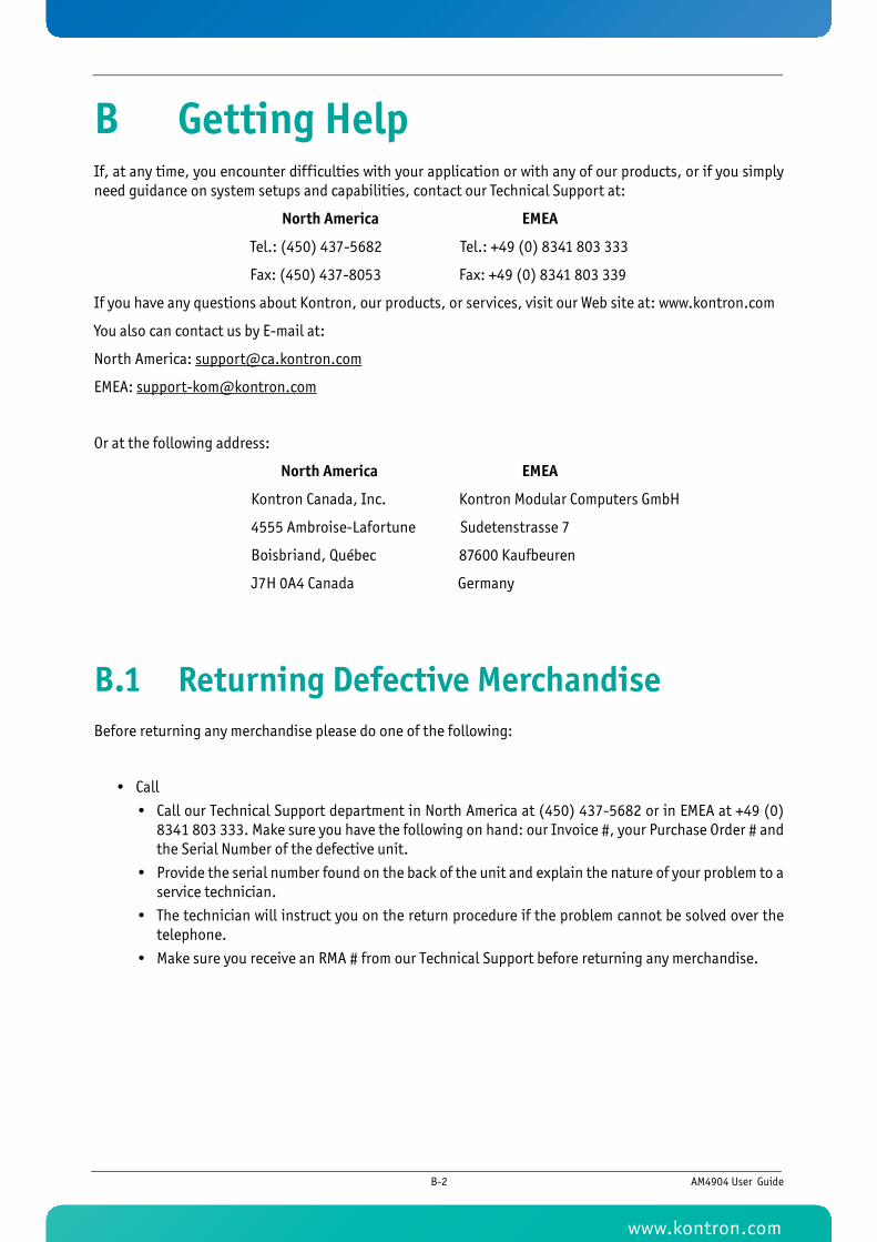
B Getting HelpIf, at any time, you encounter difficulties with your application or with any of our products, or if you simplyneed guidance on system setups and capabilities, contact our Technical Support at:
North America EMEA
Tel.: (450) 437-5682 Tel.: +49 (0) 8341 803 333
Fax: (450) 437-8053 Fax: +49 (0) 8341 803 339
If you have any questions about Kontron, our products, or services, visit our Web site at: www.kontron.com
You also can contact us by E-mail at:
North America: [email protected]
EMEA: [email protected]
Or at the following address:
North America EMEA
Kontron Canada, Inc. Kontron Modular Computers GmbH
4555 Ambroise-Lafortune Sudetenstrasse 7
Boisbriand, Québec 87600 Kaufbeuren
J7H 0A4 Canada Germany
B.1 Returning Defective MerchandiseBefore returning any merchandise please do one of the following:
• Call
• Call our Technical Support department in North America at (450) 437-5682 or in EMEA at +49 (0)8341 803 333. Make sure you have the following on hand: our Invoice #, your Purchase Order # andthe Serial Number of the defective unit.
• Provide the serial number found on the back of the unit and explain the nature of your problem to aservice technician.
• The technician will instruct you on the return procedure if the problem cannot be solved over thetelephone.
• Make sure you receive an RMA # from our Technical Support before returning any merchandise.
B-2 AM4904 User Guide
www.kontron.com
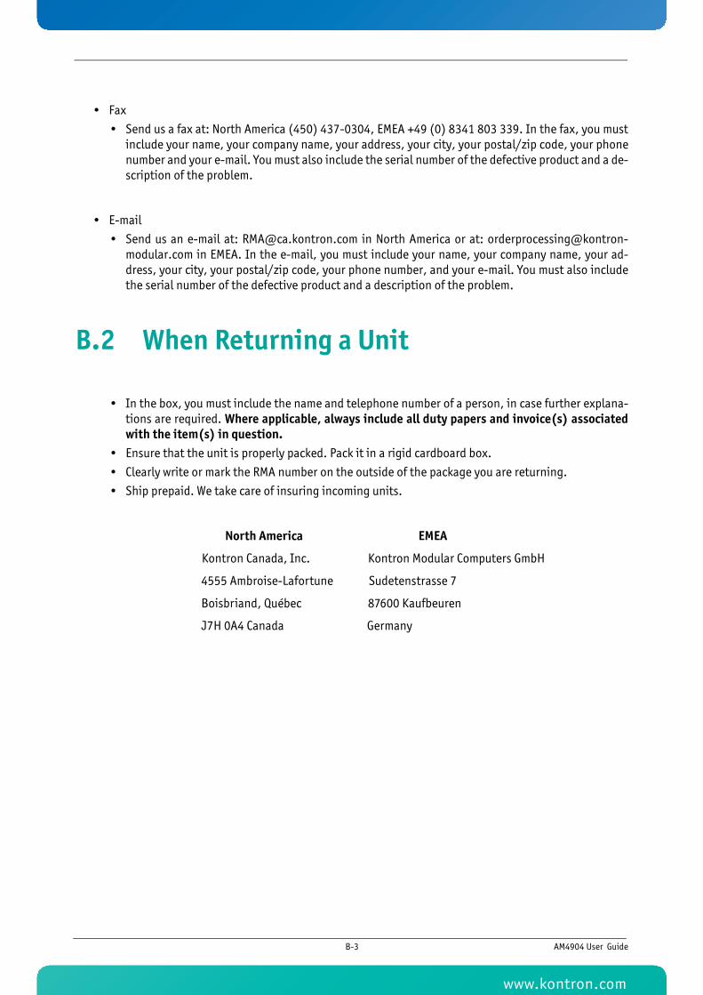
• Fax
• Send us a fax at: North America (450) 437-0304, EMEA +49 (0) 8341 803 339. In the fax, you mustinclude your name, your company name, your address, your city, your postal/zip code, your phonenumber and your e-mail. You must also include the serial number of the defective product and a de-scription of the problem.
• Send us an e-mail at: [email protected] in North America or at: [email protected] in EMEA. In the e-mail, you must include your name, your company name, your ad-dress, your city, your postal/zip code, your phone number, and your e-mail. You must also includethe serial number of the defective product and a description of the problem.
B.2 When Returning a Unit
• In the box, you must include the name and telephone number of a person, in case further explana-tions are required. Where applicable, always include all duty papers and invoice(s) associatedwith the item(s) in question.
• Ensure that the unit is properly packed. Pack it in a rigid cardboard box.
• Clearly write or mark the RMA number on the outside of the package you are returning.
• Ship prepaid. We take care of insuring incoming units.
North America EMEA
Kontron Canada, Inc. Kontron Modular Computers GmbH
4555 Ambroise-Lafortune Sudetenstrasse 7
Boisbriand, Québec 87600 Kaufbeuren
J7H 0A4 Canada Germany
B-3 AM4904 User Guide
www.kontron.com

1KTC5520/EATX
Appendix C
Glossary
www.kontron.com
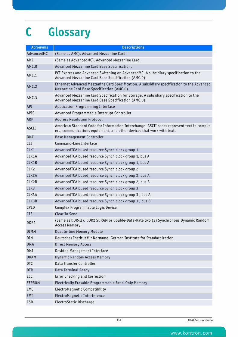
C GlossaryAcronyms Descriptions
AdvancedMC (Same as AMC). Advanced Mezzanine Card.
AMC (Same as AdvancedMC). Advanced Mezzanine Card.
AMC.0 Advanced Mezzanine Card Base Specif ication.
AMC.1 PCI Express and Advanced Switching on AdvancedMC. A subsidiary specif ication to the Advanced Mezzanine Card Base Specif ication (AMC.0).
AMC.2 Ethernet Advanced Mezzanine Card Specif ication. A subsidiary specif ication to the Advanced Mezzanine Card Base Specif ication (AMC.0).
AMC.3 Advanced Mezzanine Card Specif ication for Storage. A subsidiary specif ication to the Advanced Mezzanine Card Base Specif ication (AMC.0).
API Application Programming Interface
APIC Advanced Programmable Interrupt Controller
ARP Address Resolution Protocol
ASCII American Standard Code for Information Interchange. ASCII codes represent text in comput-ers, communications equipment, and other devices that work with text.
BMC Base Management Controller
CLI Command-Line Interface
CLK1 AdvancedTCA bused resource Synch clock group 1
CLK1A AdvancedTCA bused resource Synch clock group 1, bus A
CLK1B AdvancedTCA bused resource Synch clock group 1, bus A
CLK2 AdvancedTCA bused resource Synch clock group 2
CLK2A AdvancedTCA bused resource Synch clock group 2, bus A
CLK2B AdvancedTCA bused resource Synch clock group 2, bus B
CLK3 AdvancedTCA bused resource Synch clock group 3
CLK3A AdvancedTCA bused resource Synch clock group 3 , bus A
CLK3B AdvancedTCA bused resource Synch clock group 3 , bus B
CPLD Complex Programmable Logic Device
CTS Clear To Send
DDR2 (Same as DDR-II). DDR2 SDRAM or Double-Data-Rate two (2) Synchronous Dynamic Random Access Memory.
DIMM Dual In-line Memory Module
DIN Deutsches Institut für Normung. German Institute for Standardization.
DMA Direct Memory Access
DMI Desktop Management Interface
DRAM Dynamic Random Access Memory
DTC Data Transfer Controller
DTR Data Terminal Ready
ECC Error Checking and Correction
EEPROM Electrically Erasable Programmable Read-Only Memory
EMC ElectroMagnetic Compatibility
EMI ElectroMagnetic Interference
ESD ElectroStatic Discharge
C-2 AM4904 User Guide
www.kontron.com
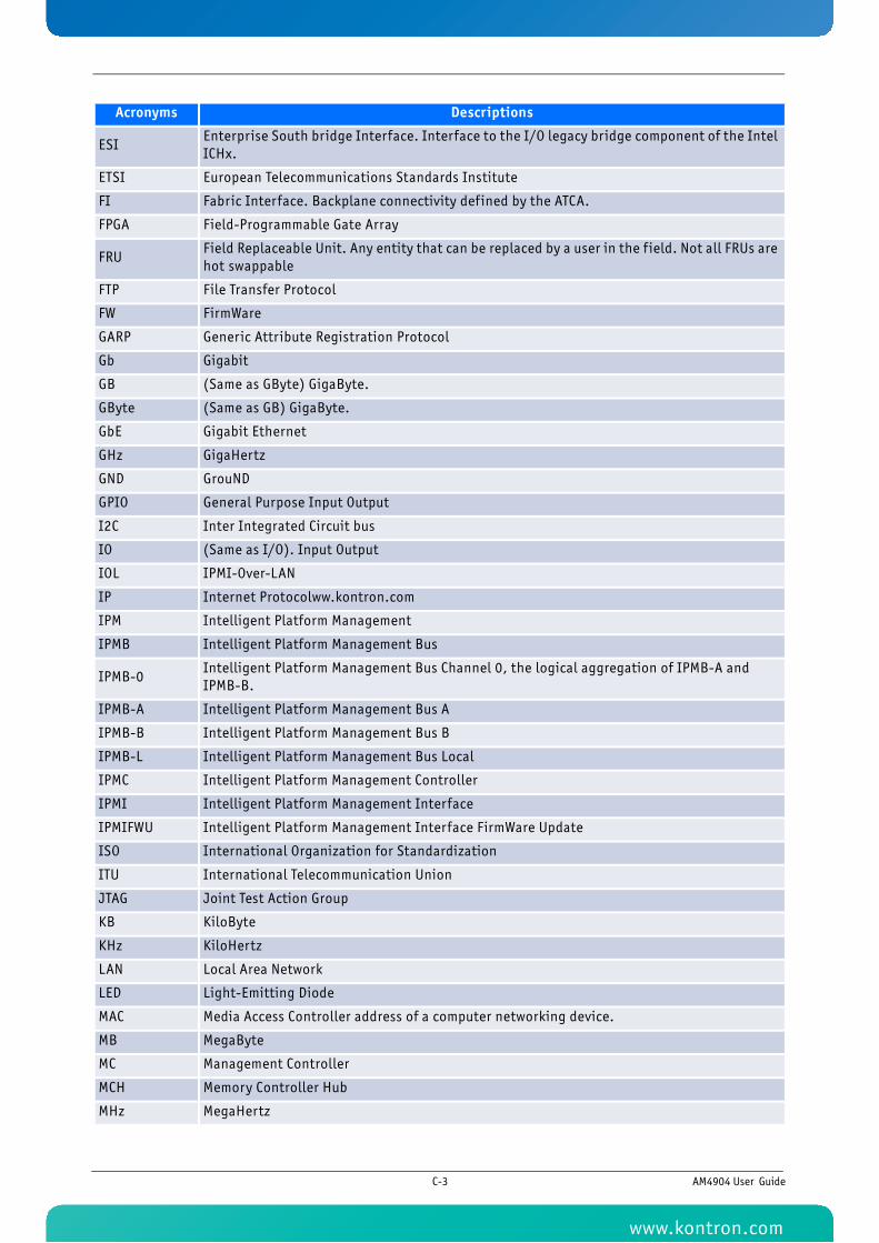
ESI Enterprise South bridge Interface. Interface to the I/O legacy bridge component of the Intel ICHx.
ETSI European Telecommunications Standards Institute
FI Fabric Interface. Backplane connectivity defined by the ATCA.
FPGA Field-Programmable Gate Array
FRU Field Replaceable Unit. Any entity that can be replaced by a user in the f ield. Not all FRUs are hot swappable
FTP File Transfer Protocol
FW FirmWare
GARP Generic Attribute Registration Protocol
Gb Gigabit
GB (Same as GByte) GigaByte.
GByte (Same as GB) GigaByte.
GbE Gigabit Ethernet
GHz GigaHertz
GND GrouND
GPIO General Purpose Input Output
I2C Inter Integrated Circuit bus
IO (Same as I/O). Input Output
IOL IPMI-Over-LAN
IP Internet Protocolww.kontron.com
IPM Intelligent Platform Management
IPMB Intelligent Platform Management Bus
IPMB-0 Intelligent Platform Management Bus Channel 0, the logical aggregation of IPMB-A and IPMB-B.
IPMB-A Intelligent Platform Management Bus A
IPMB-B Intelligent Platform Management Bus B
IPMB-L Intelligent Platform Management Bus Local
IPMC Intelligent Platform Management Controller
IPMI Intelligent Platform Management Interface
IPMIFWU Intelligent Platform Management Interface FirmWare Update
ISO International Organization for Standardization
ITU International Telecommunication Union
JTAG Joint Test Action Group
KB KiloByte
KHz KiloHertz
LAN Local Area Network
LED Light-Emitting Diode
MAC Media Access Controller address of a computer networking device.
MB MegaByte
MC Management Controller
MCH Memory Controller Hub
MHz MegaHertz
Acronyms Descriptions
C-3 AM4904 User Guide
www.kontron.com
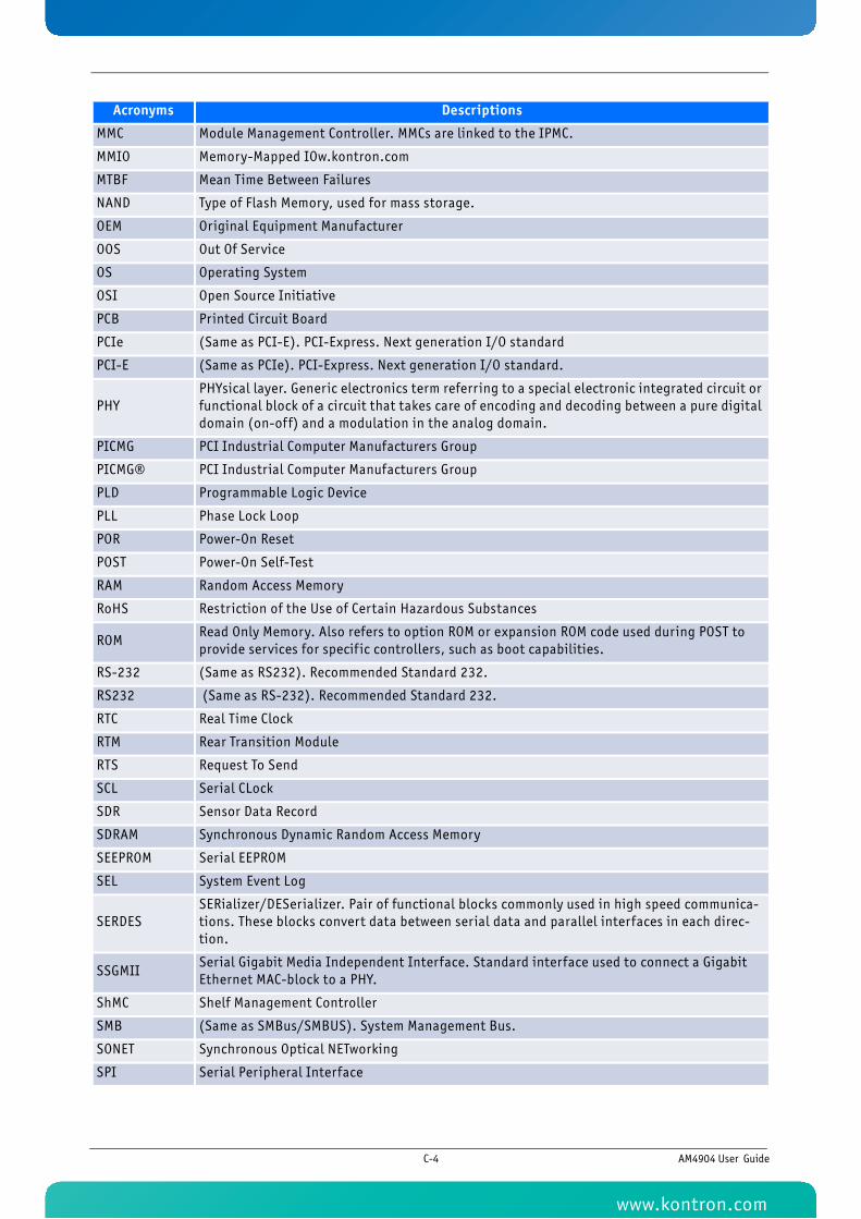
MMC Module Management Controller. MMCs are linked to the IPMC.
MMIO Memory-Mapped IOw.kontron.com
MTBF Mean Time Between Failures
NAND Type of Flash Memory, used for mass storage.
OEM Original Equipment Manufacturer
OOS Out Of Service
OS Operating System
OSI Open Source Initiative
PCB Printed Circuit Board
PCIe (Same as PCI-E). PCI-Express. Next generation I/O standard
PCI-E (Same as PCIe). PCI-Express. Next generation I/O standard.
PHYPHYsical layer. Generic electronics term referring to a special electronic integrated circuit or functional block of a circuit that takes care of encoding and decoding between a pure digital domain (on-off) and a modulation in the analog domain.
PICMG PCI Industrial Computer Manufacturers Group
PICMG® PCI Industrial Computer Manufacturers Group
PLD Programmable Logic Device
PLL Phase Lock Loop
POR Power-On Reset
POST Power-On Self-Test
RAM Random Access Memory
RoHS Restriction of the Use of Certain Hazardous Substances
ROM Read Only Memory. Also refers to option ROM or expansion ROM code used during POST to provide services for specif ic controllers, such as boot capabilities.
RS-232 (Same as RS232). Recommended Standard 232.
RS232 (Same as RS-232). Recommended Standard 232.
RTC Real Time Clock
RTM Rear Transition Module
RTS Request To Send
SCL Serial CLock
SDR Sensor Data Record
SDRAM Synchronous Dynamic Random Access Memory
SEEPROM Serial EEPROM
SEL System Event Log
SERDESSERializer/DESerializer. Pair of functional blocks commonly used in high speed communica-tions. These blocks convert data between serial data and parallel interfaces in each direc-tion.
SSGMII Serial Gigabit Media Independent Interface. Standard interface used to connect a Gigabit Ethernet MAC-block to a PHY.
ShMC Shelf Management Controller
SMB (Same as SMBus/SMBUS). System Management Bus.
SONET Synchronous Optical NETworking
SPI Serial Peripheral Interface
Acronyms Descriptions
C-4 AM4904 User Guide
www.kontron.com
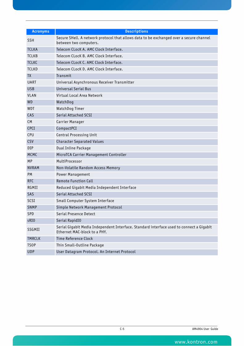
SSH Secure SHell. A network protocol that allows data to be exchanged over a secure channel between two computers.
TCLKA Telecom CLocK A. AMC Clock Interface.
TCLKB Telecom CLocK B. AMC Clock Interface.
TCLKC Telecom CLocK C. AMC Clock Interface.
TCLKD Telecom CLocK D. AMC Clock Interface.
TX Transmit
UART Universal Asynchronous Receiver Transmitter
USB Universal Serial Bus
VLAN Virtual Local Area Network
WD WatchDog
WDT WatchDog Timer
CAS Serial Attached SCSI
CM Carrier Manager
CPCI CompactPCI
CPU Central Processing Unit
CSV Character Separated Values
DIP Dual Inline Package
MCMC MicroTCA Carrier Management Controller
MP MultiProcessor
NVRAM Non-Volatile Random Access Memory
PM Power Management
RFC Remote Function Call
RGMII Reduced Gigabit Media Independent Interface
SAS Serial Attached SCSI
SCSI Small Computer System Interface
SNMP Simple Network Management Protocol
SPD Serial Presence Detect
sRIO Serial RapidIO
SSGMIISerial Gigabit Media Independent Interface. Standard interface used to connect a Gigabit Ethernet MAC-block to a PHY.
TMRCLK Time Reference Clock
TSOP Thin Small-Outline Package
UDP User Datagram Protocol. An Internet Protocol
Acronyms Descriptions
C-5 AM4904 User Guide
www.kontron.com