Embed Size (px)
Citation preview
Kopeopeo Canal Remediation
Bay of Plenty Regional Council
Revised Groundwater Assessment
IZ00688-ES-GW-01-20161404 | 03
Revised G rou ndwa ter Ass essm ent Bay of Plent y Regi onal C ouncil
Document history and status
Revision Date Description By Review Approved
01 21/12/15 Draft for Client Review T Baker B Clarke B Love
02 18/01/16 Final T Baker B Clarke B Love
03 14/04/16 Map Updates T Baker
Revised Groundwater Assessment
IZ00688-ES-GW-01-20161404 i
Kopeopeo Canal Remediation
Project no: IZ006800 Document title: Revised Groundwater Assessment Document No.: IZ00688-ES-GW-01-20161404 Revision: 03 Date: 19 January 2016 Client name: Bay of Plenty Regional Council Client no: Client Reference Project manager: Project Manager Author: Tim Baker File name: I:\AENVW\Projects\IZ006800 Kopeopeo Canal\Deliverables\Reports\Further Information
Requests\Revised Groundwater Assessment\IZ006800-0009-NG-RPT-02 Final.docx
Jacobs New Zealand Limited Level 3, 86 Customhouse Quay, PO Box 10-283 Wellington, New Zealand T +64 4 473 4265 F +64 4 473 3369 www.jacobs.com
© Copyright 2016 Jacobs New Zealand Limited. The concepts and information contained in this document are the property of Jacobs. Use or copying of this document in whole or in part without the written permission of Jacobs constitutes an infringement of copyright.
Limitation: This report has been prepared on behalf of, and for the exclusive use of Jacobs’ Client, and is subject to, and issued in accordance with, the
provisions of the contract between Jacobs and the Client. Jacobs accepts no liability or responsibility whatsoever for, or in respect of, any use of, or reliance
upon, this report by any third party.
Revised Groundwater Assessment
IZ00688-ES-GW-01-20161404 ii
Contents Executive Summary .........................................................................................................................................1 1. Introduction ..........................................................................................................................................2 1.1 Introduction ............................................................................................................................................2 1.2 Scope ....................................................................................................................................................2 2. Description of Current Methodology ...................................................................................................3 2.1 Containment Cell Construction ...............................................................................................................3 2.2 Main Pathways for Dioxin Transport .......................................................................................................3 3. Description of Proposed New Methodology .......................................................................................4 3.1 Containment Cell Construction ...............................................................................................................4 3.2 Main Pathways for Dioxin Transport .......................................................................................................4 4. Assessment of Effects .........................................................................................................................5 5. Revised Monitoring ..............................................................................................................................6 6. Conclusion ...........................................................................................................................................7 1. Groundwater....................................................................................................................................... 10 1.1 Background Groundwater Sampling ..................................................................................................... 10 1.1.1 Purpose ............................................................................................................................................... 10 1.1.2 Method................................................................................................................................................. 10 1.1.3 Location ............................................................................................................................................... 10 1.1.4 Frequency ............................................................................................................................................ 10 1.2 Long-term Groundwater Monitoring ...................................................................................................... 11 1.2.1 Purpose ............................................................................................................................................... 11 1.2.2 Method................................................................................................................................................. 11 1.2.3 Location ............................................................................................................................................... 11 1.2.4 Frequency ............................................................................................................................................ 11 1.2.5 Trigger Levels ...................................................................................................................................... 12 1.2.6 Corrective Actions ................................................................................................................................ 12 Appendix A. Revised Conceptual Containment Cell Design Appendix B. Revised Groundwater Monitoring Programme
Revised Groundwater Assessment
IZ00688-ES-GW-01-20161404 1
Executive Summary The Bay of Plenty Regional Council (BOPRC) engaged Jacobs New Zealand Limited (Jacobs) to provide an updated comparative assessment of groundwater effects from the Kopeopeo Remediation Project containment cells.
The current resource consents for the project provide for the excavation of dioxin-contaminated sediment from the bed of the Kopeopeo Canal and deposition within three geotextile lined containment cells. The sediment is dewatered and then treated using a bioremediation process.
BOPRC are considering an alternative method for extracting, transporting and containing the sediment. The new methodology comprises of dewatering the sediment in large geotextile tubes (“geotubes”) and draining the filtrate back into the canal. There will be no changes to the location of the containment sites; however the design of the bunds and internal layout of the sites is likely to change. The most significant change relevant to groundwater is that the containment cells will be lined with an HDPE liner to collect filtrate and stormwater within the containment cells.
This assessment has found that the change in containment cell design will result in the removal of the two contaminant migration pathways identified in the original assessment. These pathways are the movement of dissolved dioxins in groundwater and the movement of dioxins by colloidal transport in groundwater. With the removal of these pathways, the resultant risk of groundwater contamination has reduced, and is now considered highly unlikely.
Revised Groundwater Assessment
IZ00688-ES-GW-01-20161404 2
1. Introduction 1.1 Introduction
The Kopeopeo Canal Remediation project involves the removal and treatment of dioxin contaminated sediment from the Kopeopeo Canal near Whakatane in the Bay of Plenty. As part of the original consent application process, Jacobs completed an assessment of environmental effects (AEE) of the containment cell remediation process on groundwater. This AEE and the accompanying evidence from the consent hearing concluded that there was unlikely to be any significant effects on groundwater quality as a result of colloidal transport from the containment cells.
The current resource consents for the project provide for the excavation of dioxin-contaminated sediment from the bed of the Kopeopeo Canal and deposition within three geotextile lined containment cells. The sediment is dewatered and then treated using a bioremediation process.
The Remedial Action Plan, and Environmental Monitoring and Validation Plan provided in support of the resource consent applications set out a programme of groundwater monitoring to ensure there are no significant adverse effects on groundwater in the vicinity of the containment sites.
BOPRC are considering an alternative method for extracting, transporting and containing the sediment. The new methodology involves the use of a cutter suction dredge to excavate sediment from the canal bed and pipe it as slurry (comprising of 3% solids) to the containment sites. At the containment sites the slurry is treated with a flocculent and then pumped into large geotextile tubes (“geotubes”) for dewatering. Water draining out of the geotubes (“filtrate”) will be collected and treated to remove contaminants prior to discharging back into the canal. There will be no changes to the location of the containment sites; however the design of the bunds and internal layout of the sites is likely to change. The most significant change relevant to groundwater is that the containment cells will be lined with an HDPE liner to collect filtrate and stormwater within the containment cells.
1.2 Scope The Bay of Plenty Regional Council (BOPRC) has requested that Jacobs provide an updated comparative assessment of groundwater effects between the consented and new project methodologies. This assessment is focussed on the effects on groundwater from the containment cells. An assessment of the effects of all other aspects of the remedial methodology is specifically excluded from this report.
Revised Groundwater Assessment
IZ00688-ES-GW-01-20161404 3
2. Description of Current Methodology 2.1 Containment Cell Construction Three containment sites are proposed, these are referred to as CS1, CS2 and CS3. The current containment cell design at the containment sites consists of a large bunded cell, which is divided into sub-cells by the use of internal bunds. Each sub-cell is lined with a permeable geotextile fabric which is designed to act as a filter and prevent all but the finest colloidal material from leaving the cell. Excavated sludge is placed directly in the cells, and is allowed to drain naturally through the base of the cells.
Once dewatered, the sediment is inoculated with fungi, trees are planted and the bioremediation process commences.
2.2 Main Pathways for Dioxin Transport Two potential pathways were identified in the original AEE (SKM, 2013) and the evidence presented at the consent hearing by Mr Tim Baker, Senior Hydrogeologist with Jacobs. These pathways were the movement of dissolved dioxins in groundwater, and the movement of dioxins by colloidal transport in groundwater.
Dioxins are hydrophobic and adsorb to soil particles. Due to their very low solubility dioxins do not readily dissolve in water. According to USEPA Technical Factsheet on Dioxin (EPA Website) at 25°C, 19.3 ng of 2,3,7,8-TCDD dissolves in 1 litre of water (i.e., very low concentrations which are almost undetectable). Porewater analysis which was carried out when developing the remediation methodology indicated that water draining from sediment that had been removed from the canal contains very low levels of dioxins (within background levels of 1.2 to 5.4 pg I-TEQ/L)1.
As such, it was previously concluded that there are unlikely to be any significant effects on groundwater quality as a result of pore water drainage from the containment cells. Monitoring of groundwater quality was proposed and detailed in the Environmental Monitoring and Validation Plan (EMVP).
A potential pathway for dioxin movement away from the containment cells is via the movement of colloidal size material in subsurface groundwater movement. This is often referred to as colloidal facilitated transport. This was discussed in detail in the evidence of Mr Tim Baker, and it was concluded that colloidal transport is unlikely to occur where silts and clays are present as the colloidal material will not travel through a matrix comprising the same size material. Silts and clays are present beneath the base of CS1 and CS2. . The groundwater table at CS3 is high, and the site is located on a site already contaminated by dioxins, so the potential for additional effects is considered negligible.
1 TEQ = Toxicity equivalencies
Revised Groundwater Assessment
IZ00688-ES-GW-01-20161404 4
3. Description of Proposed New Methodology 3.1 Containment Cell Construction
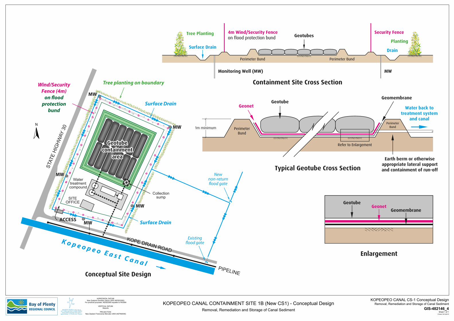
The revised construction methodology is fundamentally different from the original design. The key difference is that the containment cells are lined with an impermeable High Density Polyethylene (HDPE) liner (of approximately 1.5 mm thickness). The sediment removed from the canal will be dewatered in geotubes within the lined containment cells, and the treated water discharged back into the canal. A conceptual design of the new construction is provided in Appendix A.
Once dewatered, the sediment is inoculated with fungi, trees are planted and the bioremediation process commences.
HDPE ponds are constructed by rolling out sheets of HDPE into place. The sheets are then hot edge welded together to form a water tight seal. This form of construction is typically referred to as wedge or fusion welding. The process creates a double-track weld along the length of overlapping sheets of HDPE. The cavity between the sheets is then sealed at each end and pumped with air until it reaches the test pressure. If the air pressure holds without dropping more than the allowable percentage over a set period of time, the seam is considered compliant.
3.2 Main Pathways for Dioxin Transport The use of an impermeable HDPE liner removes both of the dioxin transport pathways that are present in the current containment cell design. These pathways are the movement of dissolved dioxins in groundwater and the movement of dioxins by colloidal transport in groundwater. The filtrate from the geotubes will be collected from an engineered sump in the base of the containment cell and discharged back to the canal. Filtrate will not drain into groundwater.
Revised Groundwater Assessment
IZ00688-ES-GW-01-20161404 5
4. Assessment of Effects As described above in Sections 2 and 3, the change in containment cell construction will result in an impermeable containment cell, which (assuming it is properly constructed) will not allow any of the filtrate from the sediment to migrate into the groundwater in and around the containment cell.
This alternative construction methodology removes the two contaminant transport pathways identified in the original consent application. These pathways are the movement of dissolved dioxins in groundwater and the movement of dioxins by colloidal transport in groundwater. Based on this revised methodology, the risk of groundwater contamination has reduced, and is now considered to be negligible.
During the 2013 consent process a submitter raised concern over the presence of percolines/preferential flow paths that may be present beneath the base of CS1 and CS2. The outcome of this was the recommendation to remove these preferential flow paths by excavation and backfilling with a low permeability material. Given the change in methodology, there is no longer any need to remove these zones during the construction of the containment cells.
Revised Groundwater Assessment
IZ00688-ES-GW-01-20161404 6
5. Revised Monitoring Given the reduced risk of groundwater contamination a reduced ground water monitoring programme is justified. The revised monitoring plan is provided in Appendix A, along with updated figures and a sampling and analysis plan table. In summary the key changes to the plan are:
Reduction in the frequency of water level monitoring from monthly to bi-monthly (every two months) Reduction in the frequency of groundwater monitoring immediately following the placement of sediment
from monthly to quarterly Reduction in long term monitoring from six-monthly to annual Reduction in the number of monitoring wells required to be monitored.
Revised Groundwater Assessment
IZ00688-ES-GW-01-20161404 7
6. Conclusion Overall, the change in containment cell design significantly reduces the risk of groundwater contamination occurring as a result of the placement of sediment into the three containment cells currently consented. The use of an impermeable HDPE will, as long as it is constructed properly, prevent filtrate (the seepage water) from migrating into shallow groundwater at and beneath the containment sites.

Revised Groundwater Assessment
IZ00688-ES-GW-01-20161404
Appendix A. Revised Conceptual Containment Cell Design
4m Wind/Security Fenceon flood protection bund
Security Fence
Surface DrainDrain
Tree Planting
Perimeter Bund
PerimeterBund
Perimeter Bund
PerimeterBund
Refer to Enlargement
Water back totreatment system
and canal
Geomembrane
Geonet
Earth berm or otherwiseappropriate lateral supportand containment of run-off
Geotubes
Monitoring Well (MW) MW
Planting
Geotube
1m minimum
GeotubeGeonet
Geomembrane
N
KOPE DRAIN ROAD
STAT
E H
IGH
WAY
30
K o p e o p e o E a s t C a n a l
Tree planting on boundary
Surface Drain
Wind/SecurityFence (4m)
on �oodprotection
bund
Existing�ood gate
Surface DrainACCESS
Newnon-return�ood gate
PIPELINE
MW
MW
MW
MWMW
MW
MW
GIS-482146_4MAGNETIC NORTH on this map is221/2o (400 mils) EAST of GRID NORTH
during 2009 increasing at the rate ofapproximately 1/2o (9 mils) over 18 years.
Sheet 1 of 1
Removal, Remediation and Storage of Canal SedimentKOPEOPEO CANAL CS-1 Conceptual DesignHORIZONTAL DATUM:
New Zealand Geodetic Datum 2000 (NZGD2000)For practical purposes, NZGD2000 equates to WGS84
VERTICAL DATUM:Moturiki
PROJECTION:New Zealand Transverse Mercator 2000 (NZTM2000) Printed 18/12/2015
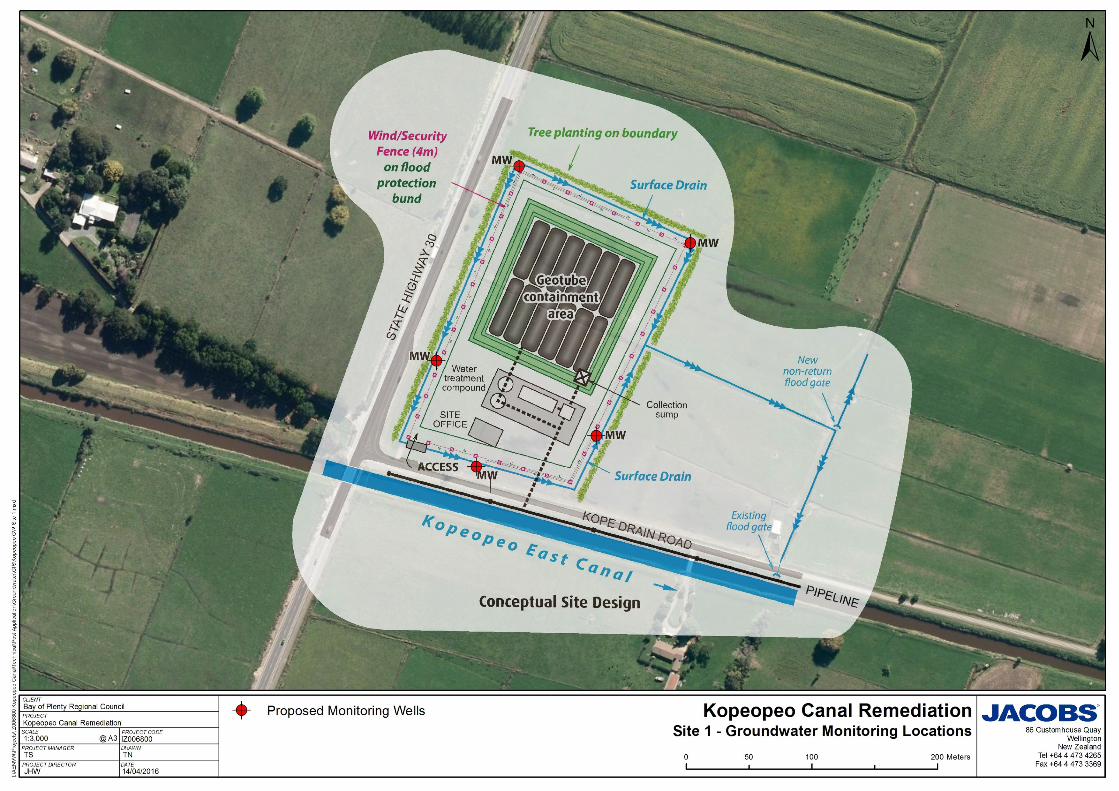
KOPEOPEO CANAL CONTAINMENT SITE 1B (New CS1) - Conceptual DesignRemoval, Remediation and Storage of Canal Sediment
Conceptual Site Design
Geotubecontainment
area
Typical Geotube Cross Section
Containment Site Cross Section
Enlargement
Watertreatmentcompound
SITEOFFICE
Collectionsump
Revised Groundwater Assessment
IZ00688-ES-GW-01-20161404
Appendix B. Revised Groundwater Monitoring Programme The following sections are taken from the groundwater section of the revised Environmental Monitoring and Validation Plan (EMVP) produced by SKM in 2014. It is envisaged that the reworded text below can be incorporated back into the EMP once the variation is approved.
Revised Groundwater Assessment
IZ00688-ES-GW-01-20161404
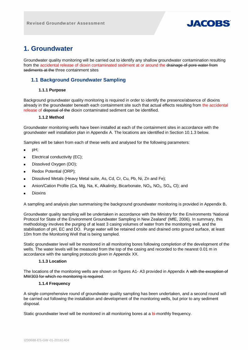
1. Groundwater Groundwater quality monitoring will be carried out to identify any shallow groundwater contamination resulting from the accidental release of dioxin contaminated sediment at or around the drainage of pore water from sediments at the three containment sites
1.1 Background Groundwater Sampling
1.1.1 Purpose
Background groundwater quality monitoring is required in order to identify the presence/absence of dioxins already in the groundwater beneath each containment site such that actual effects resulting from the accidental release of disposal of the dioxin contaminated sediment can be identified.
1.1.2 Method
Groundwater monitoring wells have been installed at each of the containment sites in accordance with the groundwater well installation plan in Appendix A. The locations are identified in Section 10.1.3 below.
Samples will be taken from each of these wells and analysed for the following parameters:
pH;
Electrical conductivity (EC);
Dissolved Oxygen (DO);
Redox Potential (ORP);
Dissolved Metals (Heavy Metal suite, As, Cd, Cr, Cu, Pb, Ni, Zn and Fe);
Anion/Cation Profile (Ca, Mg, Na, K, Alkalinity, Bicarbonate, NO3, NO2, SO4, Cl); and
Dioxins
A sampling and analysis plan summarising the background groundwater monitoring is provided in Appendix B.
Groundwater quality sampling will be undertaken in accordance with the Ministry for the Environments ‘National Protocol for State of the Environment Groundwater Sampling in New Zealand’ (MfE, 2006). In summary, this methodology involves the purging of at least 3 casing volumes of water from the monitoring well, and the stabilisation of pH, EC and DO. Purge water will be retained onsite and drained onto ground surface, at least 10m from the Monitoring Well that is being sampled.
Static groundwater level will be monitored in all monitoring bores following completion of the development of the wells. The water levels will be measured from the top of the casing and recorded to the nearest 0.01 m in accordance with the sampling protocols given in Appendix XX.
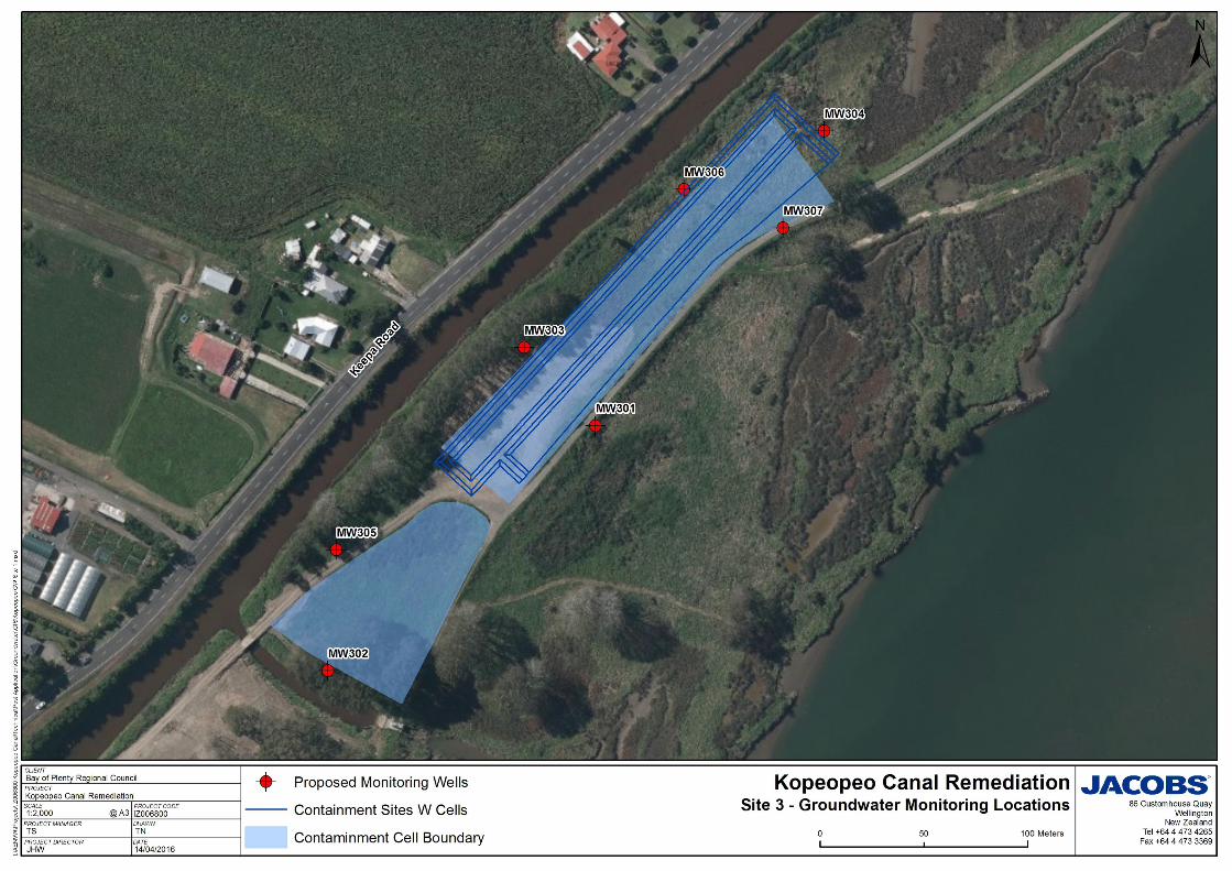
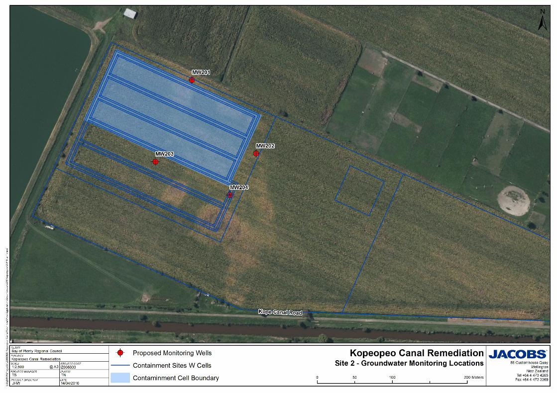
1.1.3 Location
The locations of the monitoring wells are shown on figures A1- A3 provided in Appendix A with the exception of MW303 for which no monitoring is required.
1.1.4 Frequency
A single comprehensive round of groundwater quality sampling has been undertaken, and a second round will be carried out following the installation and development of the monitoring wells, but prior to any sediment disposal.
Static groundwater level will be monitored in all monitoring bores at a bi-monthly frequency.
Revised Groundwater Assessment
IZ00688-ES-GW-01-20161404
1.2 Long-term Groundwater Monitoring
1.2.1 Purpose
Long-term groundwater quality monitoring is required in order to identify any shallow groundwater contamination resulting from any accidental releases or spillages of the drainage of pore water from sediments at the three containment sites. . Condition XX.X of the consent requires the monitoring outlined below to be undertaken following the first deposit of contaminated sediment at any one of the three containment sites.
1.2.2 Method
Groundwater will be sampled and analysed for the following parameters:
pH
Electrical conductivity
DO
ORP
Dioxins
A sampling and analysis plan summarising the long-term groundwater monitoring is provided in Appendix B.
As with the background groundwater sampling, long term groundwater quality sampling will be undertaken in accordance with the Ministry for the Environments ‘National Protocol for State of the Environment Groundwater Sampling in New Zealand’ (MfE, 2006). Purge water will be retained onsite and drained back onto the containment cell surface. Addition sampling guidance is provided in the following Work Instructions in Appendix C:
WI-006 Equipment Decontamination
WI-007 Field Control Sampling
WI-011 Groundwater Sampling
WI-023 Sample Management
Groundwater level monitoring will continue for the full duration of the remediation programme. Manual dipping may be replaced by the use of pressure transducers in representative monitoring wells. The water levels will be measured from the top of the casing and recorded to the nearest 0.01 m in accordance with the sampling protocols given in Appendix XX.
1.2.3 Location
The locations of the monitoring wells are shown on figures provided in Appendix A with the exception of MW303 for which no monitoring is required.
1.2.4 Frequency
Groundwater quality monitoring shall be undertaken at CS-1 and CS-2 following the first deposition of contaminated sediment as follows:
a. For the first 126 months following the first deposition of sediment in the containment sites (expected duration of the conditioning phase), sampling shall be undertaken at 3-monthly (i.e. quarterly) intervals;
b. For the following 18 months (i.e. months 7 to 24 from the first deposition of sediment in the containment site) sampling will be based on a rainfall trigger. Sampling shall be undertaken in accordance with the following:
i. The frequency of sampling shall be no greater than once a month;
Revised Groundwater Assessment
IZ00688-ES-GW-01-20161404
ii. Sampling shall be undertaken within 24 hours following a rainfall event of at least 5mm per 24 hour period;
iii. If there are no rainfall events equal to or exceeding 5mm per 24 hour period within any month, no sampling is required for that month;
iv. If there are no rainfall events equal to or exceeding 5mm per 24 hour period within a three month period, sampling shall be undertaken and once every three months thereafter until such time as the 5mm per 24hr rainfall trigger is met or exceeded.
b. If, following the first 12 months two years of monitoring, results show that a dioxin concentration of 30pg I-TEQ/L has not been exceeded, sampling shall continue at annual six monthly intervals for a further six years, and then annually for the remainder of the consent.
c. In the event that any monitoring undertaken after one two years produces a dioxin concentration of 30pg I-TEQ/L or more, monitoring shall be undertaken at the frequencies referred to in conditions 39.6(b), until the dioxin concentration is equal to or less than 30pg I-TEQ/L.
d. In the event that the remedial target of 40 pg/g TEQ for sediment in the containment cell is met, an appropriately qualified expert shall review the need for, and frequency of on-going groundwater monitoring. This review, including conclusions on the need for on-going monitoring, shall be peer reviewed and certified by an independent and appropriately qualified expert to verify that the need and frequency for groundwater monitoring is robust and based on valid science. The appointed peer reviewer shall be selected in agreement with the Chief Executive of the Regional Council or delegate. A copy of the report detailing the review, and the peer reviewer’s certificate shall be provided to the Chief Executive of the Regional Council within 30 working days of the completion of the reports.
At CS-3, groundwater quality monitoring will commence from the first deposit of contaminated sediment at annual six monthly intervals, or until three consecutive monitoring results show that the dioxin concentration of groundwater is at or below 30pg I-TEQ/L at which time groundwater quality monitoring at CS-3 may cease.
Static water level will continue to be monitored in all monitoring bores at a bi-monthly frequency following the first disposal of waste in the containment cell.
1.2.5 Trigger Levels
All dioxin monitoring data collected will be compared to the trigger levels set out below. A two-tier system of trigger levels is proposed as follows:
TL1 = 5.4 pg I-TEQ/L
This trigger level has been set according to the I-TEQ values for New Zealand River waters (MfE, 1998), which specifies a range of 1.2 – 5.4 pg/L. This trigger level will be reviewed once background sampling has been completed in order to confirm that this is appropriate. The New Zealand standard for river waters is similar to the Dutch Integrated SRC for groundwater which specifies an indicator level for contamination of 3 pg/L. The Dutch Integrated standard is based on both human health and ecotoxicological impacts.
TL2 = 30 pg I-TEQ/L.
This trigger level is based upon the USEPA limit for drinking water as the Drinking Water Standards for New Zealand 2005 (revised 2008) do not contain a relevant standard.
TEQ = Toxic equivalents, a method of representing the toxicity of the dioxin congener mixture relative to 2,3,7,8-tetrachlorodibenzo-p-dioxin (2,3,7,8-TCDD).
1.2.6 Corrective Actions
In the event that trigger levels are exceeded the following measures will be implemented:
Revised Groundwater Assessment
IZ00688-ES-GW-01-20161404
TL1 – This will be used as an internal indicator to initiate a review of management practices and to identify and remedy the cause of the exceedance. Where this trigger level is exceeded:
a) an additional sample will be taken as soon as practicable to confirm the result
b) a review of the bioremediation monitoring data will be carried out to identify any areas of concern (potential hotspots)
c) An inspection of the site will be carried out to identify any potential causes,
Both sets of results will be reviewed by Bay of Plenty Regional Council or nominated consultants and if necessary remedial action will be undertaken.
TL2 –If the groundwater quality Trigger Level 2 of 30pg I-TEQ/L is exceeded at any of the containment sites a Corrective Action Plan shall be implemented. The Corrective Action Plan shall be detailed in a revised Remedial Action Plan to be completed in agreement with BOPRC but will include:
a) Further investigation and sampling of the groundwater exceeding the TL
b) Possible installation of additional wells
c) Undertaking a risk assessment to determine whether the exceedence poses a risk to human health,
Any risk assessment shall be carried out by an appropriately qualified expert. The Containment Site(s) shall be managed in accordance with the recommendations contained within the risk assessment.
Revised Groundwater Assessment
IZ00688-ES-GW-01-20161404
Appendix A Monitoring Well Location Figures
Revised Groundwater Assessment
IZ00688-ES-GW-01-20161404
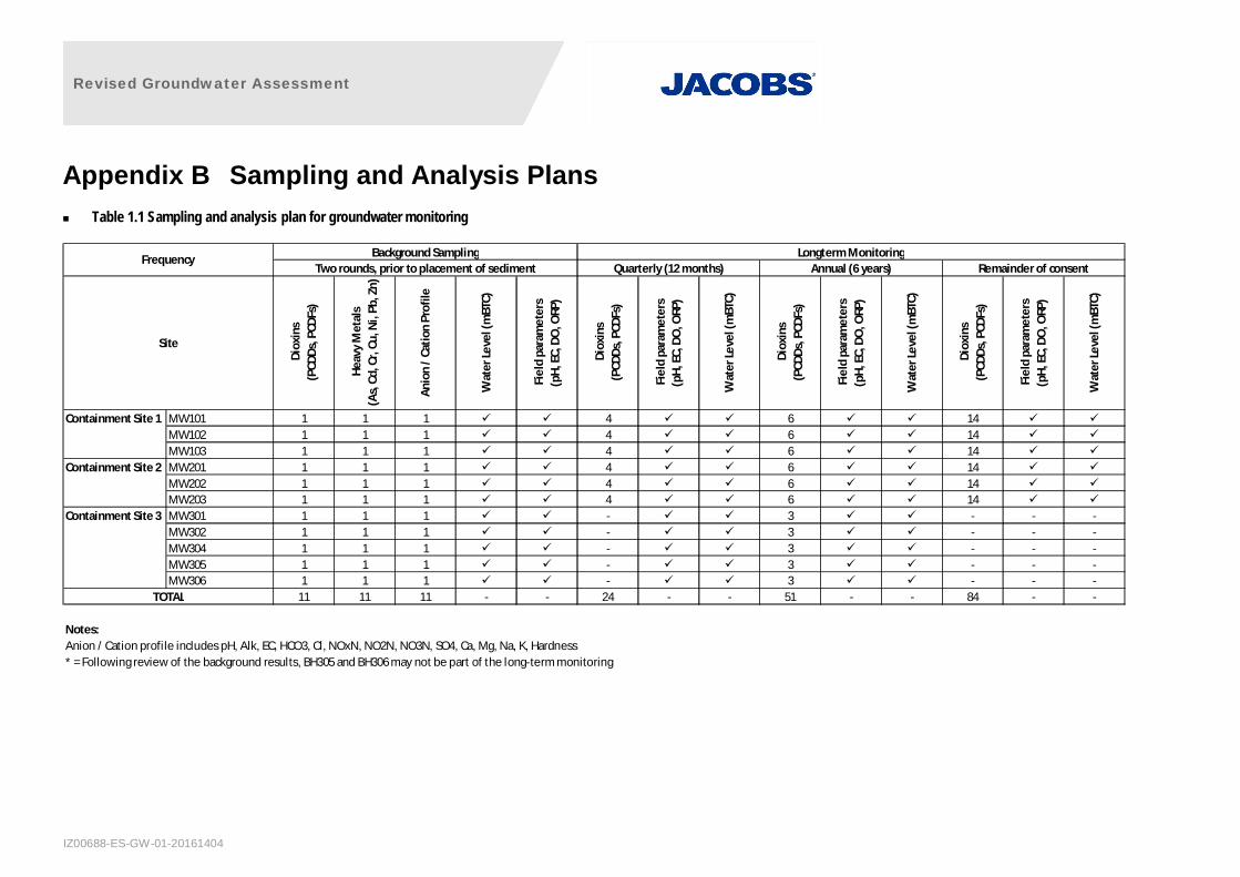
Appendix B Sampling and Analysis Plans Table 1.1 Sampling and analysis plan for groundwater monitoring
Diox
ins
(PCD
Ds, P
CDFs
)
Heav
y M
etal
s (A
s, C
d, C
r, Cu
, Ni,
Pb, Z
n)
Anio
n / C
atio
n Pr
ofile
Wat
er Le
vel (
mBT
C)
Fiel
d pa
ram
eter
s (p
H, E
C, D
O, O
RP)
Diox
ins
(PCD
Ds, P
CDFs
)
Fiel
d pa
ram
eter
s (p
H, E
C, D
O, O
RP)
Wat
er Le
vel (
mBT
C)
Diox
ins
(PCD
Ds, P
CDFs
)
Fiel
d pa
ram
eter
s (p
H, E
C, D
O, O
RP)
Wat
er Le
vel (
mBT
C)
Diox
ins
(PCD
Ds, P
CDFs
)
Fiel
d pa
ram
eter
s (p
H, E
C, D
O, O
RP)
Wat
er Le
vel (
mBT
C)
Containment Site 1 MW101 1 1 1 4 6 14MW102 1 1 1 4 6 14MW103 1 1 1 4 6 14
Containment Site 2 MW201 1 1 1 4 6 14MW202 1 1 1 4 6 14MW203 1 1 1 4 6 14
Containment Site 3 MW301 1 1 1 - 3 - - -MW302 1 1 1 - 3 - - -MW304 1 1 1 - 3 - - -MW305 1 1 1 - 3 - - -MW306 1 1 1 - 3 - - -
11 11 11 - - 24 - - 51 - - 84 - -
Notes: Anion / Cation profile includes pH, Alk, EC, HCO3, Cl, NOxN, NO2N, NO3N, SO4, Ca, Mg, Na, K, Hardness* = Following review of the background results, BH305 and BH306 may not be part of the long-term monitoring
TOTAL
Background Sampling
Site
Annual (6 years) Remainder of consentLongterm Monitoring
Two rounds, prior to placement of sedimentFrequency
Quarterly (12 months)