Embed Size (px)
Citation preview


CouplingRelays
interface
867

flare MOVE 12VDC-1W-6Aflare MOVE 12VDC-1W-AUflare MOVE 12V-1W-6Aflare MOVE 12V-1W-AUflare MOVE 24VDC-1W-6Aflare MOVE 24VDC-1W-AUflare MOVE 24V-1W-6Aflare MOVE 24V-1W-AUflare MOVE 115V-1W-6Aflare MOVE 115V-1W-AUflare MOVE 230V-1W-6Aflare MOVE 230V-1W-AU
flare MOVE 12VDC-1W-10Aflare MOVE 12VAC-1W-10Aflare MOVE 12VDC-2W-8Aflare MOVE 24VDC-1W-16Aflare MOVE 24VAC-1W-16Aflare MOVE 24VDC-2W-8Aflare MOVE 115AC-2W-8Aflare MOVE 115AC-1W-16Aflare MOVE 230AC-1W-16Aflare MOVE 230AC-2W-8A
flare -12DC-1W-250V6A-Fflare -24DC-1W-250V6Aflare -24DC-1W-250V6A-Fflare -24V-1W-48V20Mflare -24V-1W-48V20M-Fflare -24DC-2W-250V6A-Fflare -110V-1W-250V6A-Fflare -230V-1W-250V6A-Fflare -24V-1W-250V6A-CUTflare -24V-1S-250V6A-HA
R12 -12V-1W-250V5ARAB -SS 4RAB -FSS 8RAB -FSS 16RAB -SS 4 MRAB -SS 4/2RAB -SS 8/2WR 1-230-1W-250V4AWR 4-115-1W-250V4AWR 8-115-1W-250V4AWR 4-230-1W-250V4AWR 8-230-1W-250V4AWR 1-DUO-2W-250V5AWR 4-115-2W-250V4AWR 8-115-2W-250V4AWR 4-230-2W-250V4AWR 8-230-2W-250V4A
876876876876876876876876877877877877
880880880880880880881881881881
884884884884884885885885886886
890890890890890891891894894894895895896896896897897
interfaceinterfaceCoupling relaysContents
868 Subject to change without further notice
Contents – RelaysPage
Width 6.2 mm
Width 15.8 mm
Width 6.2 mm
Selection by function
General information
Pluggable interface relays
Interface relays
Relay output modules

Width 22.5 mm
Width 6.2 mm
Width 12.5 mm
Width 25.6 mm
Module base
Pluggable modules
WRS -REL-1S-250V5AWRS -REL-1S-48V20MWRS -REL-1W-250V5AWRS -REL-1W-48V20MWRS -REL-2W-250V5AWRS -REL-2W-48V20MWRS -REL-1W-250V16
NGS -12
flare -24VDC/48VDC-0,5Aflare -24VDC/48VDC-2Aflare -115V/48VDC-0,5Aflare -230VAC/48VDC-0,5Aflare -24VDC/230VAC-0,5A
WRS -SSDC-60V3AWRS -SSDC-60V5AWRS -SSAC1-250V4A
WRS -SSAC1-250V6A
M-PB 1 SRM-PB 4 SPM-PB 8 SPM-PB 4 SGM-PB 8 SG
M-IAC 24M-IDC 24OAC 3-32V/24-280VODC 3-32V/3-60VODC 3-32V/3-200V
900900900900901901901
905
906
907
909
910910910911911
914914915
915
918918918919919
920920921921922
interfaceCoupling relaysContents
869
Contents – RelaysPage
Subject to change without further notice
Relay systems
NGS coupling relays
Selection by function – Solid-state relays
Selection by function – Pluggable solid-state relays
General information – Solid-state relays
Solid-state relays
Pluggable solid-state relays

870 Subject to change without further notice
interfaceinterfaceCoupling relaysSelection by function
80.0
10.4
501.0
fl
are
MO
VE12V
DC
-1W
-6A
80.0
10.4
521.0
fl
are
MO
VE12 V
-1W
-6A
80.0
10.4
501.1
fl
are
MO
VE12V
DC
-1W
-AU
80.0
10.4
521.1
fl
are
MO
VE12V
-1W
-AU
80.0
10.4
502.0
fl
are
MO
VE24V
DC
-1W
-6A
80.0
10.4
522.0
fl
are
MO
VE24V
-1W
-6A
80.0
10.4
502.1
fl
are
MO
VE24V
DC
-1W
-AU
80.0
10.4
522.1
fl
are
MO
VE24V
-1W
-AU
80.0
10.4
525.0
fl
are
MO
VE115V
-1W
-6A
80.0
10.4
525.1
fl
are
MO
VE115V
-1W
-AU
80.0
10.4
526.0
fl
are
MO
VE230V
-1W
-6A
80.0
10.4
526.1
fl
are
MO
VE230V
-1W
-AU
80.0
10.4
701.2
fl
are
MO
VE12V
DC
-1W
-10A
80.0
10.4
711.2
fl
are
MO
VE12V
AC
-1W
-10A
80.0
10.5
101.2
fl
are
MO
VE12V
DC
-2W
-8A
80.0
10.4
902.3
fl
are
MO
VE24V
DC
-1W
-16A
80.0
10.4
912.3
fl
are
MO
VE24V
AC
-1W
-16A
80.0
10.5
102.2
fl
are
MO
VE24V
DC
-2W
-8A
80.0
10.4
915.3
fl
are
MO
VE115A
C-1
W-1
6A
80.0
10.5
315.2
fl
are
MO
VE115A
C-2
W-8
A
80.0
10.4
916.3
fl
are
MO
VE230A
C-1
W-1
6A
80.0
10.5
316.2
fl
are
MO
VE230A
C-2
W-8
A
876 876 876 876 876 876 876 876 877 877 877 877 880 880 880 880 880 880 881 881 881 881
• • • • • • • • • • • •
• • • • • • • • • •
• • • •• • • •
••
• •• •
• •• •
• •• •
• • • • • • • • • • • •• • • •
• •• • • •
• • • • • • • • • • • • • • • • • •• • • •
• • • • • • • • • • • • • • • • • • • • • •
• • • • • • • • • • • • • • • • • • • • • •• • • • • • • • • • • • • • • • • • • • • •
PART NUMBER
CATALOG PAGE
HOUSING
INPUT CIRCUIT
OUTPUT CIRCUIT
SPECIAL FUNCTION
CONNECTION STYLE
Width (mm)
DC
AC
AC/DC
AC switching capacity1)
DC switching capacity1)
Number of change-over contactsper relayNumber of normally open contactsNumber of relaysper module
Knife edge disconnect relayHand-0-Auto relayPluggable relaysScrew connectionSpring clamp connection
1) = See data sheet for detailed specification
6.212.515.822.570128280+12 V DC+24 V DC– 24 V DC12 V AC24 V AC115 V AC230 V AC12 V AC/DC24 V AC/DC28 V AC/DC115 V AC/DC230 V AC/DC1250 VA (250 V / 5 A)1500 VA (250 V / 6 A)2000 VA (250 V / 8 A)2500 VA (250 V / 10 A)4000 VA (250 V / 16 A)1 W (48 V / 20 mA)12114816

871Subject to change without further notice
interfaceCoupling relays Selection by function
80.0
10.4
000.0
fl
are
-24D
C-1
W-2
50V
6A
80.0
10.4
106.0
fl
are
-12D
C-1
W-2
50V
6A
-F
80.0
10.4
100.0
fl
are
-24D
C-1
W-2
50V
6A
-F
80.0
10.4
131.0
fl
are
-110V
-1W
-250V
6A
-F
80.0
10.4
141.0
fl
are
-230V
-1W
-250V
6A
-F
80.0
10.4
005.0
fl
are
-24V
-1W
-48V
20M
80.0
10.4
105.0
fl
are
-24V
-1W
-48V
20M
-F
80.0
10.4
103.0
fl
are
-24D
C-2
W-2
50V
6A
-F
87.2
20.7
553.0
R
12
-12V
-1W
-250V
5A
87.2
20.1
853.0
R
AB
-SS
4
87.2
20.1
953.3
R
AB
-FS
S 8
87.2
20.2
253.3
R
AB
-FS
S 1
6
87.2
21.5
553.0
R
AB
-SS
4 M
87.2
20.4
753.3
R
AB
-SS
4/2
87.2
20.4
853.3
R
AB
-SS
8/2
80.0
10.0
011.0
W
R 1
-230-1
W-2
50V
4A
80.0
10.1
102.0
W
R 4
-115-1
W-2
50V
4A
80.0
10.1
110.0
W
R 8
-115-1
W-2
50V
4A
80.0
10.1
106.0
W
R 4
-230-1
W-2
50V
4A
80.0
10.1
114.0
W
R 8
-230-1
W-2
50V
4A
80.0
10.1
100.0
W
R 1
-DU
O-2
W-2
50V
5A
80.0
10.1
104.0
W
R 4
-115-2
W-2
50V
4A
80.0
10.1
112.0
W
R 8
-115-2
W-2
50V
4A
80.0
10.1
108.0
W
R 4
-230-2
W-2
50V
4A
80.0
10.1
116.0
W
R 8
-230-2
W-2
50V
4A
80.0
10.0
005.0
W
RS
-RE
L-1
S-2
50V
5A
80.0
10.0
007.0
W
RS
-RE
L-1
S-4
8V
20M
80.0
10.0
008.0
W
RS
-RE
L-1
W-2
50V
5A
80.0
10.0
009.0
W
RS
-RE
L-1
W-4
8V
20M
80.0
10.1
003.0
W
RS
-RE
L-2
W-2
50V
5A
80.0
10.1
002.0
W
RS
-RE
L-2
W-4
8V
20M
80.0
10.0
010.0
W
RS
-RE
L-1
W-2
50V
16
80.0
10.4
120.0
fl
are
-24V
-1W
-250V
6A
-CU
T
80.0
10.4
101.0
fl
are
-24V
-1S
-250V
6A
-HA
R2.1
54.0
030.0
N
GS
12
R2.1
54.0
040.0
N
GS
12
R2.1
54.0
010.0
N
GS
12
R2.1
54.0
020.0
N
GS
12
884 884 884 885 885 884 884 885 890 890 890 890 890 891 891 894 894 894 895 895 896 896 896 897 897 900 900 900 900 901 901 901 886 886 905 905 905 905
• • • • • • • • •• • • • • • •
• • • • • • • •• • • • • • •
• • • • • ••
•• • • • • • • • • •
•
•• • • • • • • • • •
•• • • • • • •
• • • • • • • •• • • •
• • • • • • • • • • • • • •• • • • • • • • • • • • • •
•• • • • •
• • • • • • • • • • • • • • • • • • • • •• • • • • • • • • • • • • •
• • •• • • • • • • • • • • • • • • • • • • •
• • • • • • •• • • • • •
••
•• • • • • • • • • • • • • • • •
• • • • • • • • • • • • • • • • • • • • • • • • • • • • • •• • • • • • • •

Overview of the technical data
Control side – operating voltage
Wieland relay modules can be controlledwithin a defined temperature range, givenoperating voltage and relevant toleranceband to a 100% duty cycle.
Control side – Suppression circuit
AC/DC relay modules are available. DCrelays are equipped with a polarized diodeand a free-wheeling diode in the input.These functions are taken over by apower rectifier in the case of AC or AC/DCmodules. All relay modules have an LEDfor status display in the input circuit.
Suppression circuit of input for DC operation
Suppression circuit of input for AC operation
Control side – residual voltage
To ensure the safe operation of the relaythe residual voltage in the coil circuitsmust not exceed 5% DC and 15% AC ofthe operating voltage according to VDE0435. Values above this will result in therelay remaining closed after switch off.
Residual voltages can occur from solid-state devices in circuit, induced voltagesfrom high current cabling or otherinductive or capacitive interferencefactors.
Corrective measures may involve thererouting of cables away from interferenceor the parallel connection of RC elements.
Wieland relay modules – the reliableway to implement an application-related interface
In the microchip age, many believed thatelectromechanical relays would no longerplay a role. This is however far from thetruth. Switching relays have reliablyselected important tasks for many years,working in a “symbiotic relationship” withthe electronics. Relays have demonstrateda high degree of flexibility over the years.The core characteristics have beenmaintained or even improved such as:
❐ Overload capability without costlyprotection measures
❐ Contact rating of µA up to >10 A
❐ Various types and number of thecontacts
❐ High level of tolerance to electricalinterference
❐ Switching without dependence on thedirection of current (AC/DC) up to theGHz range
❐ Low level of switching power loss
❐ Electrical isolation between all contactsand the coil
Wieland offers a complete range of relaymodules with a combination of propertiesoutlined above. Depending on therequired applications, relay modules areavailable with various operating voltages,contact arrangements, contact materialsand housing designs. Timer relays orHAND-0-AUTO relays can be supplied inaddition to relays with pure monostablefunctionality.
Product range:
flare MOVE, Pluggable, process interfacerelay with an overall width of 6.2 mm
flare, process interface relay / timer relaywith an overall width of 6.2 mm
WRS, RAB, Multiple switching relaymodules with mounting base
Subject to change without further notice
interfaceinterfaceCoupling relaysGeneral information
872

Scope
mV…60 VmA…300 mA
100 mV...60 V1 mA...300 mA
>12 V1 mA...1 A
>12 V10 mA...10 A
>17 V>5 mA
>12 V>100 mA
>17 V>5 mA
µV…30 VµA…200 mA
> 100 mV> 10 µA
interface
Subject to change without further notice
Coupling relaysGeneral information
873
Load side – contact material
The contacts are used to route controlsignals in a power range of mW up tomore than 1000 VA. The contact materialthat is used is largely determined by theload expected during operation (particularlywith regard to current carrying capacity,switching frequency, operating speed aswell as any corrosive environmentalinfluences). Wieland uses the universallyaccepted AgSnO contacts for powerranges up to 1500 VA. In the lower powerrange, the same material is used but witha gold-plated finish.
Cut-out of a 3-layer welded contact with alinear contact closure
Modules with gold-flashed AgCucontacts, AgCdO or gold-plated AgNicontacts are also available. Table 1 givesan overview of other contact materials.
Table 1: Overview of contact materials
Typical properties
Low and constant contact resistance atminimum switching capacity
Free of material transfer in broad load ranges;small contact resistance; slight electric arcs; withsmaller switching capacities, higher number ofoperations and greater contact follow-through
interference possible due to friction oxides
Higher mechanical strength; low weldingtendency and higher erosion resistance than Ag;
relatively low contact resistance
Higher mechanical strength, low weldingtendency and higher erosion resistance than
fine-grained silver, but higher contact resistance
Higher erosion resistance, low weldingtendency, higher contact resistance
Low welding tendency, high erosion resistancewith higher switching capacities
Low welding tendency, very high erosionresistance with high switching capacities, low
material transfer
Good corrosion resistance, good contactresistances
Behaves as 5-µ gold contact, but its resistance towear is 5 times higher
Corrosion caused by Typical applications
Dry switching circuits, measuringcircuits, unfiltered
communication routes
Used in low and medium voltageund current ranges
Universal use in medium-sizedloads that are higher than with
fine silver
Used in medium-sized loads
Switching circuits for medium tohigh loads, DC circuits
Particularly suitable for switchinginductive loads
Switching circuits with highpower ON/OFF loads,
DC circuits
Small switching capacities for drycircuits
Minimum switching capacities upto 100 W or 1 kVA
Contact material
Gold silver AuAg10
Gold nickel AuNi5
Fine-grained silverAgNi0.15
Hard silver AgCu3
Silver nickel AgNi10
Silver cadmium oxideAgCdO10
Silver tin oxideAgSnO10
AgNi0.15+ 5 µ Au
AuAg10 over AgNi+Au
Sulfur
no
no
yes
yes
yes
yes
yes
no
no
Oxidation
no
low
no
when switching
no
no
no
yes
yes

Subject to change without further notice
interfaceinterfaceCoupling relaysGeneral information
874
Con
tact
vol
tage
[V]
Contact current [A]
Arc limit of pure contact metals
GoldSilverCopper PalladiumPlatinumTungsten Rhodium
Time t [µs]
Glow, Shower, arc discharge
Another possibility is the parallel connectionof an RC element to the load itself (seediagram above). This protective measureis equally effective. The disadvantage ofboth arrangements is the use of relativelylarge and therefore expensive capacitors.
RC circuit for AC load
A VDR resistor (Voltage DependentResistor) or varistor can be connected inparallel to the load in this application inorder to protect the contact. The resistanceof this component is low for high voltagelevels and high for low voltage levels.Varistors are therefore extremely suitablefor the suppression of arcs in AC circuits.Table 2 gives an overview of furtherpossibilities for arc suppression. Voltage characteristics at the relay
contact for inductive loads
Vol
tage
U [V
]
RC element parallel
Contact side – reduction of arcs
When the arc limit voltage (see diagram)which is dependent on the switchingcurrent and contact material is exceeded,discharge processes take place on therelay contact. Material transfer occurswhich damages the contact. To achieve along service life and a high level ofreliability despite this type of contactloading, circuit elements are required forarc suppression. Several options areavailable.
DC circuits with a resistive load
An RC element which is connected inparallel to the contact can be used for arcsuppression.
At the point of disconnection, the voltageUc at the contact jumps from zero to thevalue UxR/(R+RL) and then rises according to the function Uc=U (1-e-t/T) wherebyt=(R+RL) x C. The resistance R must behigh enough so that the combined total ofthe condenser discharge current and theswitching current at start-up is less thanthe maximum permitted starting current.
R>U / (Izul
U/R)
At a switching frequency 1/T, thecapacitor should have discharged its loadagain before the contact is reopened. Thisis essentially guaranteed if C<T/2R hasbeen selected.
DC circuits with an inductive load
While the maximum switching voltage Uis applied when a resistive load is presentat the contact, voltage peaks that areapproximately 10 times as high can occurin the case of an inductive load.
To avoid harmful discharge processes, it isnecessary to prevent a sudden disruptionin the flow of current and simultaneouslyensure that the voltage rise at the contact,which is limited by the degradation of themagnetic field, takes place at a slower ratethan the opening of the contact. Thiscounteracts the occurrence of a dischargeprocess and an air gap is therefore createdas quickly as possible after the opening ofthe contact whose igniting voltage farexceeds the voltage building up at thecontacts. An RC element which liesparallel to the contact can also be used forthis purpose.
RC element for inductive load
When the contact opens, a charging currentwhich is subsiding after an e function,flows into the capacitor. This slows downthe absorption of the current that isflowing through the inductor and the peakvalue of the voltage at the contact issimultaneously reduced. The followingserves as a practical, approximate valuefor the rating of the capacitor
C (�F) � I2/10 (A)
where I represents the respective switchingcurrent. The resistance must be rated sothat the combined total of the capacitordischarge current and the switchingcurrent is again less than the permittedstarting current.

Benefits /Disadvantages
Benefits:Simple implementationCost effectiveReliableNon-critical dimensioningSmall induced voltageDisadvantages:Attenuation only via loadresistanceLong release delayBenefits:Non-critical dimensioningDisadvantages:Attenuation only above UZD
Benefits:Cost effectiveNon-critical dimensioningSuitable for AC voltageLimit of positive peaksDisadvantages:Attenuation only above UZD
Benefits:High absorption of energyNon-critical dimensioningSuitable for AC voltageDisadvantages:Attenuation only above UVDR
Benefits:HF attenuation of storedenergySuitable for AC voltageAttenuation is not dependenton the levelDisadvantages: Exact values required High inrush currentSensitive to harmonic waves
Bipolarattenuation
no
no
yes
yes
yes
Defined limit forinduced voltage
yes (UD)
yes (UZD)
yes (UZD)
yes (UVDR)
no
Additionalrelease delay
long
medium to short
medium to short
medium to short
medium to short
interface
Subject to change without further notice
Coupling relaysGeneral information
875
Varistor:
Benefit: Low resetting time, cost-effective
Disadvantage: Cannot be used for alloperating voltages andcapacities
RC combination:
Benefit: Low overvoltage, low resetting time
Disadvantage: High current loading of thecontacts at start-up, morecostly and time-consumingwith increased capacity
Diode:
Benefit: Can be used for all capacities,low overvoltage, compact, cost-effective
Disadvantage: Very high resetting time
Diode and Zener diode:
Benefit: Low overvoltage (defined byZener diode), low resetting time
Disadvantage: Cannot be used for largecapacities
Overview of protective measures on the switch output
Life expectancy
A distinction is made in relay modulesbetween mechanical and electrical life.The mechanical life defines the maximumnumber of operating cycles withoutcontact loading while the electrical lifedescribes the switching frequency at amaximum switching capacity for resistiveload. A low switching capacity increasesthese values considerably. The followingdiagram indicates the typical waveformbetween the switching current and life ofa relay. Figures for each relay module isshown on the relevent catalogue datapage.
Typical life expectancy curve of a relay
Safety separation – VDE 0106
The safety separation of coupled switchingcircuits in the relay modules means thatthe isolating voltage between the controland load circuit is retained even in theevent of a mechanical failure (bent solderpin, broken coil winding or spring). Whenusing solid-state relays or electronic relays,this requirement is met using double orreinforced insulation. The norms DIN 50178,VDE 0106 and 109 form the basis forsafety separation. VDE 0884 also appliesto solid-state relays.
All Wieland modules meet theserequirements.
Life
cur
ve (
x104 )
30 V DC ohmic load
125 V AC ohmic load
Current (A)
Protective circuitfor load
Diode
Series-connecteddiode / Zenerdiode
Arc suppression diode
Varistor
RC-Combination

Subject to change without further notice
interfaceinterface
AgSnO2 Std. Pack AgSnO2 + Au (5 µ) Std. Pack
80.010.4502.0 10 80.010.4502.1 10
80.010.4522.0 10 80.010.4522.1 10
24 V DC 24 V AC / DC28.8 V DC 26.4 V AC / DC18.2 V DC 19.2 V AC / DC9.4 mA 12 mA0.23 W 0.3 V A(0.75...1.2) UN (0.75...1.2) UN
Up to 20 modulesLED greenAgSnO
2AgSnO
2+ Au (5 µ)
400 V AC250 V AC6 A AC / DC 1500 V A / 150 W 10 A7 ms / 11 ms20 Hz (without load); 0.1 Hz (at full load)AgSnO
2AgSnO
2+ Au (5 µ)
12 V AC / DC 5 V AC / DC10 mA AC / DC 2 mA AC / DC 500 mW 50 mW1 x 107
6 x 10⁴
250 V4 kV eff.
III (according to HD 625.1S1) 2 (according to HD 625.1S1) 0 °C...+50 °C–40 °C...+55 °CIP 20 / TS35
0.14 mm2– 1.5 mm2 / 0.5 mm2– 2.5 mm2
Part No. Std. Pack Matching relay80.063.4001.1 10 12 or 24 V DC80.063.4021.1 10 12 or 24 V DC80.063.4023.1 10 60 V DC80.063.4025.1 10 60 V DC80.063.4026.1 10 60 V DC80.063.4009.1 1080.063.4029.1 10
80.063.4129.3 1
AgSnO2 Std. Pack AgSnO2 + Au (5 µ) Std. Pack
80.063.4032.0 10 80.063.4032.1 10
Description
12 V relay module DC
24 V relay module DC
12 V relay module AC / DC
24 V relay module AC / DC
Coil circuit
Nominal operating voltageMaximum operating voltageMinimum operating voltageNominal input currentNominal input capacity AC/DCOperating rangeConnectable via pluggable jumperStatus displaySwitching characteristics
Maximum switching voltageNominal switching voltageMaximum switching currentMaximum switching capacity AC / DCMaximum starting currentPick-up/release delay (including bouncing)Maximum switching frequencyContact materialMinimum selectable voltageMinimum selectable currentMinimum switching capacityMechanical life Electrical life 230 V AC / 6 ARated voltageIsolation voltage of input/outputOvervoltage categoryDegree of pollutionAmbient temperatureStorage temperatureProtection type/mounting railEmitted interference/interference immunityWire range of screw terminal: fine-stranded/solidAccessories
Screw holder for operating voltage (6/12/24) V DCScrew holder for operating voltage (6/12/24) V AC/DCScrew holder for operating voltage (48/60) V AC/DCScrew holder for operating voltage (110...125) V AC/DCScrew holder for operating voltage (220...240) V AC/DCInsulation plate IP SF38Comb-shaped jumper for linking the terminals, continuous current 36 A, 20 pole, KB SF38Marking plate BM SF38
6 V DC relay12 V DC relay24 V DC relay
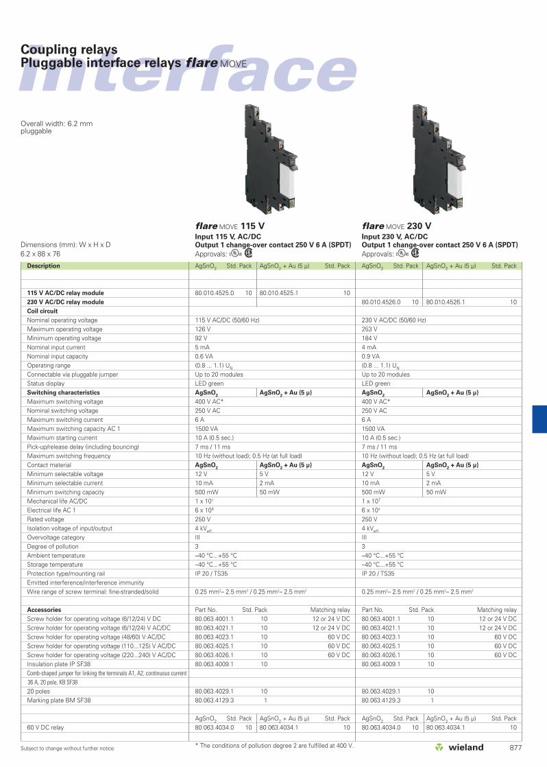
Dimensions (mm): W x H x D6.2 x 88 x 76
flare MOVE 12 VInput 12 V DC, AC/DC Output 1 change-over contact 250 V 6 A (SPDT)
Approvals: Ew
flare MOVE 24 VInput 24 V DC, AC/DC Output 1 change-over contact 250 V 6 A (SPDT)
Approvals: Ew
Overall width: 6.2 mmpluggable
Coupling relaysPluggable interface relays flare MOVE
876
AgSnO2 Std. Pack AgSnO2 + Au (5 µ) Std. Pack80.010.4501.0 10 80.010.4501.1 10
80.010.4521.0 10 80.010.4521.1 10
12 V DC 12 V AC / DC14.4 V DC 13.2 V AC / DC9.0 V DC 8.4 V AC / DC17 mA 19 mA0.2 W 0.25 V A(0.75...1.2) UN (0.7 ... 1.1) UN
Up to 20 modulesLED greenAgSnO
2AgSnO
2+ Au (5 µ)
400 V AC250 V AC6 A AC / DC 1500 V A / 150 W 10 A7 ms / 11 ms20 Hz (without load); 0.1 Hz (at full load)AgSnO
2AgSnO
2+ Au (5 µ)
12 V AC / DC 5 V AC / DC 10 mA AC / DC 2 mA AC / DC 500 mW 50 mW1 x 107
6 x 10⁴
250 V4 kV eff.
III (according to HD 625.1S1) 2 (according to HD 625.1S1) 0 °C...+50 °C –40 °C...+55 °CIP 20 / TS35
0.14 mm2– 1.5 mm2 / 0.5 mm2– 2.5 mm2
Part No. Std. Pack Matching relay80.063.4001.1 10 12 or 24 V DC80.063.4021.1 10 12 or 24 V DC80.063.4023.1 10 60 V DC80.063.4025.1 10 60 V DC80.063.4026.1 10 60 V DC80.063.4009.1 1080.063.4029.1 10
80.063.4129.3 1
AgSnO2 Std. Pack AgSnO2 + Au (5 µ) Std. Pack80.063.4030.0 10 80.063.4030.1 1080.063.4031.1 10 80.063.4031.0 10
* The conditions of pollution degree 2 are fulfilled at 400 V
interface
Subject to change without further notice
Coupling relaysPluggable interface relays flare MOVE
Overall width: 6.2 mmpluggable
Dimensions (mm): W x H x D6.2 x 88 x 76
AgSnO2 Std. Pack AgSnO2 + Au (5 µ) Std. Pack
80.010.4526.0 10 80.010.4526.1 10
230 V AC/DC (50/60 Hz)253 V 184 V 4 mA0.9 VA(0.8 ... 1.1) UN
Up to 20 modulesLED greenAgSnO
2AgSnO
2+ Au (5 µ)
400 V AC*250 V AC6 A 1500 VA 10 A (0.5 sec.)7 ms / 11 ms10 Hz (without load); 0.5 Hz (at full load)AgSnO
2AgSnO
2+ Au (5 µ)
12 V 5 V 10 mA 2 mA500 mW 50 mW1 x 107
6 x 10⁴
250 V4 kVeff.
III 3 –40 °C...+55 °C –40 °C...+55 °CIP 20 / TS35
0.25 mm2– 2.5 mm2 / 0.25 mm2– 2.5 mm2
Part No. Std. Pack Matching relay80.063.4001.1 10 12 or 24 V DC80.063.4021.1 10 12 or 24 V DC80.063.4023.1 10 60 V DC80.063.4025.1 10 60 V DC80.063.4026.1 10 60 V DC80.063.4009.1 10
80.063.4029.1 1080.063.4129.3 1
AgSnO2 Std. Pack AgSnO2 + Au (5 µ) Std. Pack80.063.4034.0 10 80.063.4034.1 10
AgSnO2 Std. Pack AgSnO2 + Au (5 µ) Std. Pack
80.010.4525.0 10 80.010.4525.1 10
115 V AC/DC (50/60 Hz)126 V92 V 5 mA0.6 VA(0.8 ... 1.1) UN
Up to 20 modulesLED greenAgSnO
2AgSnO
2+ Au (5 µ)
400 V AC*250 V AC6 A1500 VA10 A (0.5 sec.)7 ms / 11 ms10 Hz (without load); 0.5 Hz (at full load)AgSnO
2AgSnO
2+ Au (5 µ)
12 V 5 V 10 mA 2 mA 500 mW 50 mW1 x 107
6 x 10⁴
250 V4 kVeff.
III 3 –40 °C...+55 °C–40 °C...+55 °CIP 20 / TS35
0.25 mm2– 2.5 mm2 / 0.25 mm2– 2.5 mm2
Part No. Std. Pack Matching relay80.063.4001.1 10 12 or 24 V DC80.063.4021.1 10 12 or 24 V DC80.063.4023.1 10 60 V DC80.063.4025.1 10 60 V DC80.063.4026.1 10 60 V DC80.063.4009.1 10
80.063.4029.1 1080.063.4129.3 1
AgSnO2 Std. Pack AgSnO2 + Au (5 µ) Std. Pack80.063.4034.0 10 80.063.4034.1 10
* The conditions of pollution degree 2 are fulfilled at 400 V.
Description
115 V AC/DC relay module
230 V AC/DC relay module
Coil circuit
Nominal operating voltageMaximum operating voltageMinimum operating voltageNominal input currentNominal input capacity Operating rangeConnectable via pluggable jumperStatus displaySwitching characteristics
Maximum switching voltageNominal switching voltageMaximum switching currentMaximum switching capacity AC 1Maximum starting currentPick-up/release delay (including bouncing)Maximum switching frequencyContact materialMinimum selectable voltageMinimum selectable currentMinimum switching capacityMechanical life AC/DCElectrical life AC 1Rated voltageIsolation voltage of input/outputOvervoltage categoryDegree of pollutionAmbient temperatureStorage temperatureProtection type/mounting railEmitted interference/interference immunityWire range of screw terminal: fine-stranded/solid
Accessories
Screw holder for operating voltage (6/12/24) V DCScrew holder for operating voltage (6/12/24) V AC/DCScrew holder for operating voltage (48/60) V AC/DCScrew holder for operating voltage (110...125) V AC/DCScrew holder for operating voltage (220...240) V AC/DCInsulation plate IP SF38Comb-shaped jumper for linking the terminals A1, A2, continuous current36 A, 20 pole, KB SF3820 polesMarking plate BM SF38
60 V DC relay
877
flare MOVE 115 VInput 115 V, AC/DC Output 1 change-over contact 250 V 6 A (SPDT)
Approvals: Ew
flare MOVE 230 VInput 230 V, AC/DC Output 1 change-over contact 250 V 6 A (SPDT)
Approvals: Ew

Subject to change without further notice
interfaceinterfaceCoupling relaysPluggable interface relays flare MOVE
878
Circuit diagrams: flare MOVE – mechanical relay couplers
12 V DC; AC/DC relay 1 change-over contact (SPDT)
Part No. 80.010.4521.0Part No. 80.010.4521.1
24 V DC relay, 1 change-over contact (SPDT)
Part No. 80.010.4502.0Part No. 80.010.4502.1
12 V DC relay, 1 change-over contact (SPDT)
Part No. 80.010.4501.0Part No. 80.010.4501.1
115 V AC/DC relay 1 change-over contact (SPDT)
Part No. 80.010.4525.0Part No. 80.010.4525.1
24 V DC; AC/DC relay 1 change-over contact (SPDT)
Part No. 80.010.4522.0Part No. 80.010.4522.1
230 V AC/DC relay 1 change-over contact (SPDT)
Part No. 80.010.4526.0Part No. 80.010.4526.1
Dimensions

879
interface
Subject to change without further notice
interfaceinterfaceCoupling relaysPluggable interface relays flare MOVE
880
Type Part No. Std. Pack
Flare move 24DC1W16A 80.010.4902.3 10Flare move 24AC1W16A 80.010.4912.3 10Flare move 24DC2W8A 80.010.5102.2 10DC AC24 V DC 24 V AC40.8 V DC 26.4 V AC17.5 V DC 19.2 V AC22.2 mA 46 mA0.5 W 1.2 VA(0.73 ... 1.75) UN (0.8 ... 1.1) UN
Up to 8 modulesLED green1 change-over contact 2 change-over contacts
400 V AC* 250 V AC250 V AC 250 V AC16 A 8 A AC/DC4000 VA 2000 VA30 A 15 A (0.5 sec.)15 ms / 12 ms10 Hz (without load); 0.5 Hz (at full load)AgCdO AgNi10 V AC/DC 5 V AC/DC5 mA AC/DC500 mW 300 mW2 x 107/ 1 x 10⁷ 2 x 10⁷
1 x 10⁵ 1 x 10⁵
250 V4 kV III 3 2 –40°C...+70°C –40°C...+70°CIP 20 / TS35
0.25 mm2– 4 mm2 / 0.25 mm2– 6 mm2
80.063.5132.2 1080.063.5142.2 1080.063.5232.2 10
Type Part No. Std. PackVARICLIP 80.063.5009.1 10METALL 80.063.5019.1 10KB SF48 80.063.5029.2 10BZ SF48 80.063.5029.3 10
Type Part No. Std. PackFlare move 12DC1W10A 80.010.4701.2 10Flare move 12AC1W10A 80.010.4711.2 10Flare move 12DC2W8A 80.010.5101.2 10
DC AC12 V DC 12 V AC21 V DC 13.2 V AC8.8 V DC 9.6 V AC41 mA 90.5 mA0.5 W 1.2 VA(0.73 ... 1.75) UN (0.8 ... 1.1) UN
Up to 8 modulesLED green1 change-over contact 2 change-over contacts
400 V AC* 250 V AC250 V AC 250 V AC10 A AC/DC 8 A AC/DC2500 VA 2000 VA20 A (0.5 sec.) 15 A (0.5 sec.)15 ms / 12 ms10 Hz (without load); 0.5 Hz (at full load)AgNi5 V AC/DC5 mA AC/DC300 mW2 x 107/ 1 x 10⁷ 2 x 10⁷
2 x 10⁵/ 1 x 10⁵ 1 x 10⁵
250 V4 kVIII 3 2–40°C...+70°C–40°C...+70°CIP 20 / TS35
0.25 mm2– 4 mm2 / 0.25 mm2– 6 mm2
80.063.5031.2 1080.063.5041.2 1080.063.5231.2 10
Type Part No. Std. PackVARICLIP 80.063.5009.1 10METALL 80.063.5019.1 10KB SF48 80.063.5029.2 10BZ SF48 80.063.5029.3 10
Description
Coupling relay 12V DC; 1U; AgNi; 10A
Coupling relay 12V AC; 1U; AgNi; 10A
Coupling relay 12V DC; 2U, AgNi, 8A
Coupling relay 24 V DC; 1U; AgCdO; 16 A
Coupling relay 24 V AC; 1U; AgCdO; 16 A
Coupling relay 24 V DC; 2U; AgNi; 8 A
Coil circuit (same for both contact materials)Nominal operating voltageMaximum operating voltageMinimum operating voltageNominal input currentNominal input capacity Operating rangeConnectable via pluggable jumperStatus displaySwitching characteristics
Maximum switching voltageNominal switching voltageMaximum switching currentMaximum switching capacity AC 1Maximum starting currentPick-up/release delay (including bouncing)Maximum switching frequencyContact materialMinimum selectable voltageMinimum selectable currentMinimum switching capacityMechanical life DC/ACElectrical life AC 1Rated voltageIsolation voltage of input/outputOvervoltage categoryDegree of pollutionAmbient temperatureStorage temperatureProtection type/mounting railEmitted interference/interference immunityWire range of screw terminal: fine-stranded/solidRelay type
Relay 12 V DC; 1 change-over contact; AgNi; 10 ARelay 12 V AC; 1 change-over contact; AgNi; 10 ARelay 12 V DC; 2 change-over contacts; AgNi; 8 ARelay 24 V DC; 1 change-over contact; AgCdO; 16 ARelay 24 V AC; 1 change-over contact; AgCdO; 16 ARelay 24 V DC; 2 change-over contacts; AgNi; 8 AAccessories
Variclip (plastic, black), retaining clipRetaining clip (metal)Comb shaped jumper 8 pole for linking terminals A1, A2, continuous current 10AMarking tag (plastic, white)
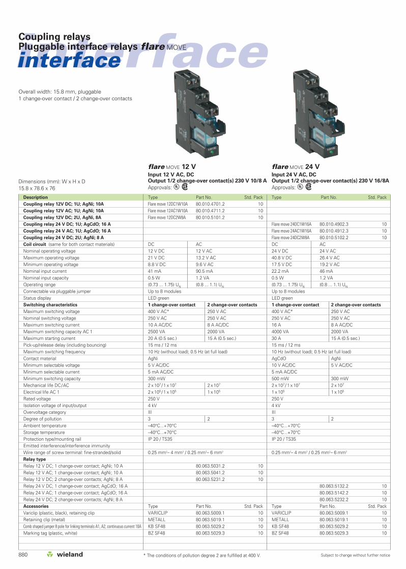
Dimensions (mm): W x H x D15.8 x 78.6 x 76
flare MOVE 12 VInput 12 V AC, DC Output 1/2 change-over contact(s) 230 V 10/8 A
Approvals: Lw
flare MOVE 24 VInput 24 V AC, DC Output 1/2 change-over contact(s) 230 V 16/8A
Approvals: Lw
Overall width: 15.8 mm, pluggable1 change-over contact / 2 change-over contacts
* The conditions of pollution degree 2 are fulfilled at 400 V.

interface
Subject to change without further notice
Coupling relaysPluggable interface relays flare MOVE
881
Overall width: 15.8 mm, pluggable1 change-over contact / 2 change-over contacts
Type Part No. Std. Pack
Flare move 230AC1W16 80.010.4916.3 10Flare move 230AC2W8 80.010.5316.2 10
230 V AC (50/60 Hz)253 V AC184 V AC7 mA1.2 VA(0.8 ... 1.1) UN
Up to 8 modulesLED green1 change-over contact 2 change-over contacts
400 V AC* 250 V AC250 V AC 250 V AC16 A 8 A 4000 VA 2000 VA30 A (0.5 sec.) 15 A (0.5 sec.)10 ms / 10 ms10 Hz (without load); 0.5 Hz (at full load)AgCdO AgNi10 V AC/DC 5 V AC/DC5 mA AC/DC 5 mA AC/DC500 mW 300 mW1 x 107
1 x 10⁵
250 V4 kV III 3 2–40 °C...+70 °C –40 °C...+70 °CIP 20 / TS35
0.25 mm2– 4 mm2 / 0.25 mm2– 6 mm2
80.063.5146.2 1080.063.5246.2 10
Type Part No. Std. PackVARICLIP 80.063.5009.1 10METALL 80.063.5019.1 10KB SF48 80.063.5029.2 10BZ SF48 80.063.5029.3 10
Type Part No. Std. PackFlare move 115AC1W16 80.010.4915.3 10Flare move 115AC2W8 80.010.5315.2 10
115 V AC (50/60 Hz)121 V AC88 V AC10.1 mA1.2 VA(0.8 ... 1.1) UN
Up to 8 modulesLED green1 change-over contact 2 change-over contacts
400 V AC* 250 V AC250 V AC 250 V AC16 A** 8 A4000 VA 2000 VA30 A (0.5 sec.) 15 A (0.5 sec.)10 ms / 10 ms10 Hz (without load); 0.5 Hz (at full load)AgCdO AgNi10 V AC/DC 5 V AC/DC5 mA AC/DC 5 mA AC/DC500 mW 300 mW1 x 107/ 1 x 10⁷
1 x 10⁵ / 1 x 10⁵
250 V4 kV III 3 2–40 °C...+70 °C –40 °C...+70 °CIP 20 / TS35
0.25 mm2 – 4 mm2 / 0.25 mm2– 6 mm2
80.063.5145.2 1080.063.5245.2 10
Type Part No. Std. PackVARICLIP 80.063.5009.1 10METALL 80.063.5019.1 10KB SF48 80.063.5029.2 10BZ SF48 80.063.5029.3 10
Description
Coupling relay 115V AC; 1U; AgCdO; 16A
Coupling relay 115V AC; 2U, AgNi; 8A
Coupling relay 230V AC; 1U; AgCdO; 16A
Coupling relay 230V AC; 2U, AgNi; 8A
Coil circuit
Nominal operating voltageMaximum operating voltage Minimum operating voltageNominal input currentNominal input capacity Operating rangeConnectable via pluggable jumperStatus displaySwitching characteristics
Maximum switching voltageNominal switching voltageMaximum switching currentMaximum switching capacity AC 1Maximum starting currentPick-up/release delay (including bouncing)Maximum switching frequencyContact materialMinimum selectable voltageMinimum selectable currentMinimum switching capacityMechanical life AC/DCElectrical life AC 1Rated voltageIsolation voltage of input/outputOvervoltage categoryDegree of pollutionAmbient temperatureStorage temperatureProtection type/mounting railEmitted interference/interference immunityWire range of screw terminal: fine-stranded/solid
Relay type
Relay 115 V AC; 1 change-over contact; AgCdO; 16 ARelay 115 V AC; 2 change-over contacts; AgNi; 8 A
Relay 230 V AC; 1 change-over contact; AgCdO; 16 ARelay 230 V AC; 2 change-over contacts; AgNi; 8 A
Accessories
Variclip (plastic, black), retaining clipRetaining clip (metal)Comb shaped jumper 8 pole for linking terminals A1, A2, continuous current 10AMarking tag (plastic, white)
Dimensions (mm): W x H x D15.8 x 78.6 x 76
flare MOVE 115 V ACInput 115 V AC Output 1/2 change-over contact(s) 250 V 16/8 A
Approvals: Lw
flare MOVE 230 V ACInput 230 V AC Output 1/2 change-over contact(s) 230 V 16/8 A
Approvals: Lw
* The conditions of pollution degree 2 are fulfilled at 400 V** Continuous current >10 A requires jumpering of the terminals 11-21, 14-24, 12-22

Subject to change without further notice
interfaceinterfaceCoupling relaysPluggable interface relays flare MOVE
882
Circuit diagrams: flare MOVE – mechanical relay couplers
12 V AC relayPart No. 80.010.4711.2
24 V AC relayPart No. 80.010.4912.3
12 V DC relayPart No. 80.010.4701.2
24 V DC relayPart No. 80.010.4902.3
12 V DC relayPart No. 80.010.5101.2
24 V DC relayPart No. 80.010.5102.2
115 V AC relayPart No. 80.010.4915.3
230 V AC relayPart No. 80.010.4916.3
115 V AC relayPart No. 80.010.5315.2
230 V AC relayPart No. 80.010.5316.2
Dimensions

883
interface

Subject to change without further notice
interfaceinterfaceCoupling relaysInterface relays
884
Type Part No. Std. Pack
flare-24V-1W-48V20M-F 80.010.4105.0 10flare-24V-1W-48V20M 80.010.4005.0 10
24 V +25 % / -20 %ca. 14 mAca. 0.35 W> 1.2 mAUp to 50 modulesLED green
48 V DC20 mA1.2 W
8 ms / 20 ms2 ms< 0.1 Hz (50% ED)AgSnO2 + 3µ Au5 V1 mA2 x 107
6 x 10⁵
8 x 10⁴
4 kVeff.
III (according to HD 625.1S1) 2 (according to HD 625.1S1) 0 °C...+60 °C (Derating) –40 °C...+85 °CIP 20 / TS35VDE 0160; VDE 0106 T101EN 61000-6-3; EN 61000-6-2
0.5 mm2 – 2.5 mm2 | 0.25 mm2 – 1.5 mm2
0.25 mm2 – 4 mm2 | 0.25 mm2 – 2.5 mm2
Class I, Division 2, Groups A, B, C and D
Z8.000.0200.8 10Z4.242.5153.0 10Z8.000.0202.3 / Z8.000.0202.4 5Z8.000.0202.1 / Z8.000.0202.2 20
Type Part No. Std. Packflare-12DC-1W-250V6A-F 80.010.4106.0 10flare-24DC-1W-250V6A-F 80.010.4100.0 10flare-24DC-1W-250V6A 80.010.4000.0 10
12 V +25 % / 17 % 24 V +25 % / -20 %ca. 18 mA ca. 14 mAca. 0.22 W ca. 0.35 W> 2.3 mA > 1.2 mAUp to 50 modulesLED green
250 V AC / 300 V DC6 A AC / 2 A DC1500 VA / 120 W10 A; 4 sec.15 ms / 20 ms 8 ms / 10 ms2 ms< 0.1 Hz (50% ED)AgSnO2
24 V8 mA1 x 107
6 x 10⁵
8 x 10⁴
4 kVeff.
III (according to HD 625.1S1) 2 (according to HD 625.1S1) 0 °C... +60 °C (Derating)–40 °C...+85 °CIP 20 / TS35VDE 0160; VDE 0106 T101EN 61000-6-3; EN 61000-6-2
0.5 mm2 – 2.5 mm2 | 0.25 mm2 – 1.5 mm2
0.25 mm2 – 4 mm2 | 0.25 mm2 – 2.5 mm2
Class I, Division 2, Groups A, B, C and D
Z8.000.0200.8 10Z4.242.5153.0 10Z8.000.0202.3 /Z8.000.0202.4 5Z8.000.0202.1 / Z8.000.0202.2 20
Description
12 V DC spring clamp connection
24 V DC spring clamp connection
24 V DC screw connection
24 V AC/DC spring clamp connection
24 V AC/DC screw connection
Coil circuit
Operating voltageNominal input currentNominal input capacityHolding current at 20 °CConnectable via pluggable jumperStatus display
Switching characteristics
Maximum switching voltageMaximum switching currentMaximum switching capacityMaximum starting currentPick-up/release delayBouncing timeMaximum switching frequencyContact materialMinimum selectable voltageMinimum selectable currentMechanical lifeElectrical life 24 V DC / 2 AElectrical life 230 V AC / 6 ARated voltageIsolation voltage of input/outputOvervoltage categoryDegree of pollutionAmbient temperatureStorage temperatureProtection type/mounting railStandards/specificationsEmitted interference/interference immunityWire range of screw terminal/spring clamp terminal
fine-strandedsolid
CSA EX approval in range
Accessories
Pluggable jumper (Umax = 50 V, Imax = 2 A)8 digit marking tag, unmarked, 60 pcs.Comb for potential distribution, red/blue*End caps for comb red/blue* for screw terminals only
Dimensions (mm): W x H x D6.2 x 89 x 70
flare 12/24 V DCInput 12/24 V DCOutput 1 change-over contact AC 250 V 6 A / DC 300 V 2 A (SPDT)
Approvals:qwh
flare 24 V AC/DCInput 24 V AC/DCOutput 1 change-over contact DC 48 V 20 mA(SPDT)
Approvals:qwh
Overall width 6.2 mmScrew or spring clamp terminal can be selected

interface
Subject to change without further notice
Coupling relaysInterface relays
885
flare 24 VInput 24 V DC Output 2 change-over contacts AC 250 V 6 A / DC 300 V 2 A (DPDT)12.4 x 89 x 70Approvals:qwh
Dimensions (mm): W x H x D
flare 115/230 V ACInput 115/230 V ACOutput 1 change-over contact AC 250 V 6 A / DC 300 V 2 A (SPDT)6.2 x 89 x 70Approvals:qwh
Type Part No. Std. Packflare-24DC-2W-250V6A-F 80.010.4103.0 5
24 V +25 %/–20 %ca. 18 mAca. 0.45 W> 2 mAUp to 50 modulesLED green
250 V AC 6 A AC / 2 A DC1500 VA / 120 W10 A; 4 sec.ca. 15 ms / 20 ms2 ms< 0.1 Hz (50% ED)AgSnO2
12 V5 mA2 x 107
8 x 10⁵
6 x 10⁴
4 kVeff.
III (according to HD 625.1S1) 2 (according to HD 625.1S1) 0 °C...+60 °C (Derating)–40 °C...+85 °CIP 20 / TS35VDE 0160; VDE 0106 T101EN 61000-6-3; EN 61000-6-2
0.25 mm2 – 1.5 mm2
0.25 mm2 – 2.5 mm2
Z8.000.0200.8 10Z4.242.5153.0 10
Type Part No. Std. Pack
flare-110V-1W-250V6A-F 80.010.4131.0 10flare-230V-1W-50V6A-F 80.010.4141.0 10
115 V +10 % / -15 % 230 V + 10 % / - 15 %ca. 3.9 mA ca. 3 mAca. 0.48 W ca. 0.65 W> 0.6 mA > 0.3 mAUp to 50 modulesLED green
250 V AC / 300 V DC6 A AC / 2 A DC1500 VA / 120 W10 A; 4 sec.8 ms / 10 ms2 ms< 10 HzAgSnO2
24 V8 mA2 x 107
6 x 10⁵
8 x 10⁴
4 kVeff.
III (according to HD 625.1S1) 2 (according to HD 625.1S1) 0 °C...+60 °C (Derating)–40 °C...+85 °CIP 20 / TS35VDE 0160; VDE 0106 T101EN 61000-6-3; EN 61000-6-2
0.25 mm2 – 1.5 mm2
0.25 mm2 – 2.5 mm2
Class I, Division 2, Groups A, B, C and D
Z8.000.0200.8 10Z4.242.5153.0 10
Description
24 V DC spring clamp connection
115 V AC spring clamp connection
230 V AC spring clamp connection
Coil circuit
Operating voltageNominal input currentNominal input capacityHolding current at 20 °CConnectable via pluggable jumperStatus display
Switching characteristics
Maximum switching voltageMaximum switching currentMaximum switching capacityMaximum starting currentPick-up/release delayBouncing timeMaximum switching frequencyContact materialMinimum selectable voltageMinimum selectable currentMechanical lifeElectrical life 24 V DC / 2 AElectrical life 230 V AC / 6 ARated voltageIsolation voltage of input/outputOvervoltage categoryDegree of pollutionAmbient temperatureStorage temperatureProtection type/mounting railStandards/specificationsEmitted interference/interference immunityWire range of screw terminal/spring clamp terminal
fine-strandedsolid
CSA EX approval in range
Accessories
Pluggable jumper (Umax = 50 V, Imax = 2 A)8 digit marking tag, unmarked, 60 pcs.

Subject to change without further notice
interfaceinterfaceCoupling relaysInterface relays
886
Type Part No. Std. Packflare-24V-1W-250V6A-CUT 80.010.4120.0 10
24 V AC/DC +25 %/–20 %ca. 14 mAca. 0.35 W> 1.2 mAUp to 50 modulesLED green
250 V AC / 300 V DC6 A AC / 2 A DC1500 VA / 120 W10 A; 4 sec.8 ms / 20 ms2 ms< 0.1 Hz (50 % ED)AgSnO2
24 V8 mA2 x 107
6 x 10⁵
8 x 10⁴
4 kVeff.
III (according to HD 625.1S1) 2 (according to HD 625.1S1) 0 °C...+60 °C (Derating)–40 °C...+85 °CIP 20 / TS35VDE 0160; VDE 0106 T101EN 61000-6-3; EN 61000-6-2–
0.25 mm2 – 1.5 mm2
0.25 mm2 – 2.5 mm2
Class I, Division 2, Groups A, B, C and D
Z8.000.0200.8 10Z4.242.5153.0 10
CuZn37F38-3µAgCuSn6FB370-3µAg
Type Part No. Std. Packflare-24V-1S-250V6A-HA 80.010.4101.0 10
24 V AC/DC +25 %/–20 %ca. 14 mAca. 0.35 W> 1.2 mAUp to 50 modulesLED green
250 V AC / 300 V DC6 A AC / 2 A DC1500 VA / 48 W10 A; 4 sec.8 ms / 20 ms2 ms< 0.1 Hz (50 % ED)AgSnO2
24 V8 mA2 x 107
6 x 10⁵
8 x 10⁴
4 kVeff.
III (according to HD 625.1S1) 2 (according to HD 625.1S1) 0 °C...+60 °C (Derating)–40 °C...+85 °CIP 20 / TS35VDE 0160; VDE 0106 T101EN 61000-6-3; EN 61000-6-2–
0.25 mm2 – 1.5 mm2
0.25 mm2 – 2.5 mm2
Class I, Division 2, Groups A, B, C and D
Z8.000.0200.8 10Z4.242.5153.0 10
Description
24 V AC/DC spring clamp connection
Coil circuit
Operating voltageNominal input currentNominal input capacityHolding current at 20 °CConnectable via pluggable jumperStatus display
Switching characteristics
Maximum switching voltageMaximum switching currentMaximum switching capacityMaximum starting currentPick-up/release delayBouncing timeMaximum switching frequencyContact materialMinimum selectable voltageMinimum selectable currentMechanical lifeElectrical life 24 V DC / 2 AElectrical life 230 V AC / 6 ARated voltageIsolation voltage of input/outputOvervoltage categoryDegree of pollutionAmbient temperatureStorage temperatureProtection type/mounting railStandards/specificationsEmitted interference/interference immunityWire range of screw terminalWire range of spring clamp terminal
fine-strandedsolid
CSA EX approval in range
Accessories
Pluggable jumper (Umax = 50 V, Imax = 2 A)8 digit marking tag, unmarked, 60 pcs.
Contact material
RailPlug
Dimensions (mm): W x H x D6.2 x 89 x 70
flare 24 V Knife edge disconnect relayInput 24 V AC/DC Output 1 change-over contact AC 250 V 6 A /DC 300 V 2 A (SPDT)Approvals:qwh
flare 24 V HAND-0-AUTO relay Input 24 V AC/DC Output 1 normally open contact AC 250 V 6 A / DC 300 V 2 A (SPDT)Approvals:qwh
Overall width: 6.2 mmIsolation in the input or in the output

interface
Subject to change without further notice
Coupling relaysInterface relays
887
Circuit diagrams: flare – mechanical relay couplers
110-V-/230-V relay 1 change-over contact (SPDT)
12-V-/24-V relay 1 change-over contact (SPDT)
24-V relay 2 change-over contacts (DPDT)
Knife edge disconnect relay Hand-0-Auto relay(SPST, N.O.)
Housing with screw terminalsHousing with spring clamp terminals Connection of knife edge disconnectrelay
Subject to change without further notice
interfaceinterfaceCoupling relaysInterface relays
888
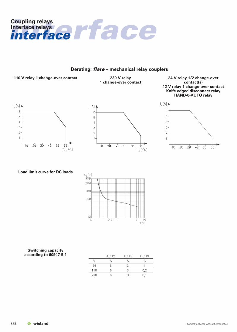
Derating: flare – mechanical relay couplers
230 V relay 1 change-over contact
24 V relay 1/2 change-overcontact(s)
12 V relay 1 change-over contact Knife edged disconnect relay
HAND-0-AUTO relay
110 V relay 1 change-over contact
Load limit curve for DC loads
Switching capacity according to 60947-5.1 AC 12 AC 15 DC 13
V A A A24 6 3 1110 6 3 0,2230 6 3 0,1

889
interface

890 Subject to change without further notice
interfaceinterfaceCoupling relaysRelay output modules
Description
1 relay
4 relay positive switching
8 relay positive switching
16 relay positive switching
4 relay negative switching
Coil circuit
Operating voltageNominal input current per inputNominal input capacityHolding current at 20 °CStatus display
Switching characteristics
Maximum switching voltageMaximum switching currentMaximum switching capacityMaximum continuous currentPick-up/release delay approx.Bouncing timeMaximum switching frequencyContact materialMinimum selectable voltageMinimum selectable currentMechanical lifeElectrical life 24 V DC / 2 AElectrical life 230 V AC / 6 ARated voltageIsolation voltage of input/outputOvervoltage categoryDegree of pollutionAmbient temperatureStorage temperatureMounting railStandards/specificationsEmitted interference/interference immunityWire range, fine-stranded/solidLocation of mounting rail
Accessories
Replacement relay
1) See limit curve on page 892
Dimensions (mm): W x H x D
R12-12V-1WInput 12 V AC/DCOutput 1 change-over contact 250 V AC 5 A (SPDT)
12.5 x 80 x 58.3
Relay output modules– 1 relay– 4 relay– 8 relay– 16 relay
RAB 4/8/16Input 24 V DCOutput 1 change-over contact 250 V AC 5 A (SPDT)
70/128/280 x 80 x 71
Type Part No. Std. PackR12-12V-1W-250V5A 87.220.7553.0 10
12 V AC/DC ±10%34 mA0.4 W> 2 mALED green
250 V AC / 1)V DC8 A AC/ 1)A DC2000 VA / 120 W5 A AC/DC1)
9 ms / 12 ms4 ms40 HzAgCdO12 V100 mA3 x 107
6 x 10⁵
6 x 10⁵
4 kVeff.
–25 °C...Derating–40 °C...+85 °CTS 32 or TS 35
0.5 mm2 – 2.5 mm2 / 0.5 mm2 – 4 mm2
horizontal
Z8.000.0056.9 10
Type Part No. Std. Pack
RAB-SS 4 87.220.1853.0 1RAB-FSS 8 87.220.1953.3 1RAB-FSS 16 87.220.2253.3 1RAB-SS 4 M 87.221.5553.0 1
24 V DC +10%/–15%25 mA0.6 W> 2 mALED green
250 V AC / 1)V DC8 A AC/ 1)A DC2000 VA / 120 W5 A AC/DC1)
9 ms / 12 ms4 ms40 HzAgCdO12 V100 mA3 x 107
6 x 10⁵
6 x 10⁵
4 kVeff.
–25 °C...Derating–40 °C...+85 °CTS 32 or TS 35
0.5 mm2 – 2.5 mm2 / 0.5 mm2 – 4 mm2
horizontal
Z8.000.0056.9 10

interface
Subject to change without further notice
Coupling relaysRelay output modules
891
Type Part No. Std. Pack
RAB-SS 4/2 87.220.4753.3 1RAB-SS 8/2 87.220.4853.3 1
24 V DC + 10 %/– 15 %
25 mA0.6 W> 2 mALED green
250 V AC / 1)V DC8 A AC/ 1)A DC2000 VA / 120 W5 A AC/DC1)
9 ms / 12 ms4 ms40 HzAgCdO12 V100 mA3 x 107
6 x 10⁵
6 x 10⁵
4 kVeff.
–25 °C...Derating–40 °C...+85 °CTS 32 or TS 35
0.5 mm2 – 2.5 mm2 / 0.5 mm2 – 4 mm2
horizontal
Z8.000.0035.5 10
Dimensions (mm): W x H x D
RAB 4/8 Input 24 V DC Output 2 change-over contacts 250 V AC 5 A (DPDT)
70/128 x 80 x 71
Relay output modules– 4 relay– 8 relay
Important note for users:
In the case of multiple modules (1 change-over contact/2 change-over contacts), the outputs must be supplied fromthe same phase (e.g. L1)
Description
1 relay
4 relay positive switching
8 relay positive switching
16 relay positive switching
4 relay negative switching
Coil circuit
Operating voltageNominal input currentNominal input capacityHolding current at 20 °CStatus display
Switching characteristics
Maximum switching voltageMaximum switching currentMaximum switching capacityMaximum continuous currentPick-up/release delay approx.Bouncing timeMaximum switching frequencyContact materialMinimum selectable voltageMinimum selectable currentMechanical lifeElectrical life 24 V DC / 2 AElectrical life 230 V AC / 6 ARated voltageIsolation voltage of input/outputOvervoltage categoryDegree of pollutionAmbient temperatureStorage temperatureMounting railStandards/specificationsEmitted interference/interference immunityWire range, fine-stranded/solidLocation of mounting rail
Accessories
Replacement relay
1) See limit curve on page 892

Subject to change without further notice
interfaceinterfaceCoupling relaysRelay output modules
892
Circuit diagrams
Derating
RAB – 1 change-over contact RAB – 2 change-over contactsR12-12V-1W 250 V 5 A
RAB-FSS and RAB-SSR12-12V-1W 250 V 5 A
Dimensions
RAB – 1 change-over contact RAB – 2 change-over contactsR12-12V-1W 250 V 5 A
a = continuous operationb = switching operation 50% duty cycle

893
interface

Subject to change without further notice
interfaceinterface
894
Dimensions (mm): W x H x D
WR 1-230-1WInput 230 V AC/DC Output 1 change-over contact 250 V AC 4 A (SPDT)12.5 x 80 x 70
Relay modules input/output– 1 relay– 4 relay– 8 relay
WR 4/8-115-1W Input 115 V AC/DC Output 1 change-over contact 250 V AC 4 A (SPDT)
70/128 x 80 x 71
Coupling relaysRelay output modules
Description
1 relay
4 relay
8 relay
Coil circuit
Operating voltageNominal input current per inputNominal input capacityHolding current at 20 °CSuppression circuit for inputStatus display
Switching characteristics
Maximum switching voltageMaximum switching currentMaximum switching capacityMaximum continuous currentPick-up/release delay approx.Bouncing timeMaximum switching frequencyContact materialMinimum selectable voltageMinimum selectable currentMechanical lifeElectrical life 24 V DC / 2 AElectrical life 230 V AC / 6 ARated voltageIsolation voltage of input/outputOvervoltage categoryDegree of pollutionAmbient temperatureStorage temperatureMounting railStandards/specificationsEmitted interference/interference immunityWire range, fine-stranded/solidLocation of mounting rail
Accessories
Replacement relay
1) See limit curve on page 899
Type Part No. Std. PackWR1-230-1W-250V4A 80.010.0011.0 10
230 V AC/DC +6% / –10%ca. 4.5 mA ACca. 1.0 VA> 0.9 mA ACpolarized diode, arc suppression diodeLED green
250 V AC/ 1)V DC8 A AC/1)A DC2000 VA /192 W4 A AC/DC10 ms /15 ms4 ms40 HzAgNi + 4...6 µ AuµVµA3 x 107
3 x 10⁵
3 x 10⁵
4 kVeff.
–25 °C...Derating–40 °C...+80 °CTS 32 or TS 35
0.5 mm2 – 2.5 mm2 / 0.5 mm2 – 4 mm2
horizontal
Type Part No. Std. Pack
WR4-115-1W-250V4A 80.010.1102.0 1WR8-115-1W-250V4A 80.010.1110.0 1
115 V AC/DC +6% /–10%ca. 4.8 mA AC/DCca. 0.6 VA/W< 1 mA AC / < 0.8 mA DCpolarized diode, arc suppression diodeLED green
250 V AC / 1)V DC6 A AC/1)A DC2000 VA / 192 W4 A AC/DC9 ms / 12 ms< 4 ms40 HzAgNi 0.15 + 0.2 µ Au5 V10 mA3 x 107
1.5 x 10⁵
1.5 x 10⁵
4 kVeff.
–25 °C...+50 °C–40 °C...+80 °CTS 32 or TS 35
0.5 mm2 – 2.5 mm2 / 0.5 mm2 – 4 mm2
horizontal
Z8.000.0181.0 10

interface
Subject to change without further notice
Coupling relaysRelay output modules
895
Type Part No. Std. Pack
WR4-230-1W-250V4A 80.010.1106.0 1WR8-230-1W-250V4A 80.010.1114.0 1
230 V AC/DC +6%/–10%ca. 4.8 mA AC/DCca. 1.0 VA/W> 1 mA AC / > 0.8 mA DCpolarized diode, arc suppression diodeLED green
250 V AC / 1)V DC6 A AC / 1)A DC2000 VA / 192 W4 A AC/DC9 ms / 12 ms4 ms40 HzAgNi 0.15 + 0.2 µ Au5 V10 mA3 x 107
1.5 x 10⁵
1.5 x 10⁵
4 kVeff.
–25 °C...+50 °C–40 °C...+80 °CTS 32 or TS 35
0.5 mm2 – 2.5 mm2 / 0.5 mm2 – 4 mm2
horizontal
Z8.000.0181.0 10
Dimensions (mm): W x H x D
WR 4/8-230-1WInput 230 V AC/DC Output 1 change-over contact 250 V AC 4 A (SPDT)
70/128 x 80 x71
Relay module input/output– 4 relay– 8 relay
Description
1 relay
4 relay
8 relay
Coil circuit
Operating voltageNominal input current per inputNominal input capacityHolding current at 20 °CSuppression circuit for inputStatus display
Switching characteristics
Maximum switching voltageMaximum switching currentMaximum switching capacityMaximum continuous currentPick-up/release delay approx.Bouncing timeMaximum switching frequencyContact materialMinimum selectable voltageMinimum selectable currentMechanical lifeElectrical life 24 V DC / 2 AElectrical life 230 V AC / 6 ARated voltageIsolation voltage of input/outputOvervoltage categoryDegree of pollutionAmbient temperatureStorage temperatureMounting railStandards/specificationsEmitted interference/interference immunityWire range, fine-stranded/solidLocation of mounting rail
Accessories
Replacement relay
1) See limit curve on page 899
Important note for users:
In the case of multiple modules (1 change-over contact/2 change-over contacts), the outputs must be supplied fromthe same phase (e.g. L1)

Subject to change without further notice
interfaceinterface
896
Dimensions (mm): W x H x D
WR 1-DUO-2WInput 115/230 V AC/DC Output 2 change-over contacts 250 V AC 5 A (DPDT)
22.5 x 80 x 68
Relay output modules with 2 change-over contacts– 1 relay– 4 relay– 8 relay
WR 4/8-115-2WInput 115 V AC/DC Output 2 change-over contacts 250 V AC 5 A (DPDT)
70/128 x 80 x 71
Description
1 relay
4 relay
8 relay
Coil circuit
Operating voltageNominal input current per inputNominal input capacityHolding current at 20 °CSuppression circuit for inputStatus display
Switching characteristics
Maximum switching voltageMaximum switching currentMaximum switching capacityMaximum continuous currentPick-up/release delay approx.Bouncing timeMaximum switching frequencyContact materialMinimum selectable voltageMinimum selectable currentMechanical lifeElectrical life 24 V DC / 2 AElectrical life 230 V AC / 6 ARated voltageIsolation voltage of input/outputOvervoltage categoryDegree of pollutionAmbient temperatureStorage temperatureMounting railStandards/specificationsEmitted interference/interference immunityWire range, fine-stranded/solidLocation of mounting rail
Accessories
Replacement relay
1) See limit curve on page 899
Type Part No. Std. PackWR1-DUO-2W-250V5A 80.010.1100.0 5
115/230 V AC/DC +6%/–10%ca. 4.8 mA / 4.8 mA AC/DC ca. 0.6 VA/W / 1.2 VA/W> 1.0 mA AC / > 0.8 mA DCpolarized diode, arc suppression diodeLED green
250 V AC / 1)V DC6 A AC/ 1)A DC1500 VA / 192 W5 A AC/DC (derating to be considered)9 ms / 12 ms< 4 ms
AgNi 0.15 + 0.2 µ Au5 V10 mA3 x 107
1.5 x 10⁵
1.5 x 10⁵
4 kVeff.
–25 °C... +50 °C (Derating)–40 °C... +80 °CTS 32 or TS 35
0.5 mm2 – 2.5 mm2 / 0.5 mm2 – 4 mm2
horizontal
Z8.000.0176.2 10
Type Part No. Std. Pack
WR4-115-2W-250V4A 80.010.1104.0 1WR8-115-2W-250V4A 80.010.1112.0 1
115 V AC/DC +6%/–10%ca. 4.8 mA AC/DCca. 0.6 VA/W> 1 mA AC / > 0.8 mA DCpolarized diode, arc suppression diodeLED green
250 V AC / 1)V DC6 A AC/ 1)A DC1500 VA / 192 W4 A AC/DC (derating to be considered)< 9 ms / < 12 ms< 4 ms
AgNi 0.15 + 0.2 µ Au5 V10 mA3 x 107
1.5 x 10⁵
1.5 x 10⁵
4 kVeff.
–25 °C... +50 °C (Derating)–40 °C... +80 °CTS 32 or TS 35
0.5 mm2 – 2.5 mm2 / 0.5 mm2 – 4 mm2
horizontal
Z8.000.0176.2 10
Coupling relaysRelay output modules

interface
Subject to change without further notice
Coupling relaysRelay output modules
897
Type Part No. Std. Pack
WR4-230-2W-250V4A 80.010.1108.0 1WR8-230-2W-250V4A 80.010.1116.0 1
230 V AC/DC +6%/–10%ca. 4.8 mA AC/DCca. 1.2 VA/W> 1 mA AC / > 0.8 mA DCpolarized diode, arc suppression diodeLED green
250 V AC / 1) V DC6 A AC / 1)A DC1500 VA / 192 W4 A AC/DC (derating to be considered)< 9 ms / < 12 ms< 4 ms
AgNi 0.15 + 0.2 µ Au5 V10 mA3 x 107
1.5 x 10⁵
1.5 x 10⁵
4 kVeff.
–25 °C...+50 °C (Derating)–40 °C...+80 °CTS 32 or TS 35
0.5 mm2 – 2.5 mm2 / 0.5 mm2 – 4 mm2
horizontal
Z8.000.0176.2 10
Dimensions (mm): W x H x D
WR 4/8-230-2WInput 230 V AC/DCOutput 2 change-over contacts 250 V AC 5 A (DPDT)
70/128 x 80 x 71
Relay output modules with 2 change-over contacts– 4 relay– 8 relay
Important note for users:
In the case of multiple modules (1 change-over contact/2 change-over contacts), the outputs must be supplied fromthe same phase (e.g. L1)
Description
1 relay
4 relay
8 relay
Coil circuit
Operating voltageNominal input current Nominal input capacityHolding current at 20 °CSuppression circuit for inputStatus display
Switching characteristics
Maximum switching voltageMaximum switching currentMaximum switching capacityMaximum continuous currentPick-up/release delay approx.Bouncing timeMaximum switching frequencyContact materialMinimum selectable voltageMinimum selectable currentMechanical lifeElectrical life 24 V DC / 2 AElectrical life 230 V AC / 6 ARated voltageIsolation voltage of input/outputOvervoltage categoryDegree of pollutionAmbient temperatureStorage temperatureMounting railStandards/specificationsEmitted interference/interference immunityWire range, fine-stranded/solidLocation of mounting rail
Accessories
Replacement relay
1) See limit curve on page 899

Subject to change without further notice
interfaceinterfaceCoupling relaysRelay output modules
898
Circuit diagrams
WR4/8-115-1W 250 V 4 AWR1-230-1W 250 V 4 A WR4/8-230-1W 250 V 4 A
WR4/8-115-2W 250 V 4 AWR1-DUO-2W 250 V 5 A WR4/8-230-2W 250 V 4 A

interface
Subject to change without further notice
Coupling relaysRelay output modules
899
Derating
WR1 – DUO WR4/WR8 – 2 change-over contactsWR1 – 1 change-over contact
Dimensions
WR4/WR8 – 1 change-over contactWR1 – DUOWR1 – 1 change-over contact
WR4/WR8 – 2 change-over contacts
a = side by side without spacingb = side by side with spacing of 5 mm

Subject to change without further notice
interfaceinterfaceCoupling relaysRelay systems
900
Type Part No. Std. PackWRS-REL-1W-250V5A 80.010.0008.0 10WRS-REL-1W-48V20M 80.010.0009.0 10
24 V DC +10%/–15%25 mAca. 0.6 W/VA≥ 2 mA20 relaysPolarized diode, arc suppression diodeLED green
Output Input
250 V AC/DC2) 48 V DC8 A AC/DC2) 20 mA2000 VA / 192 W 1.2 W5 A AC/DC8 ms / 8 ms 10 ms / 10 ms3 ms 3 msAgCdO AgNi 0.15 + 10 µ Au12 V µV100 mA µA3 x 107 3 x 10⁷
3 x 10⁵
2.5 x 10⁵
2.5 x 10⁵
4 kVeff. 4 kVeff.
–25 °C...+65 °C (Derating) –25 °C...+50 °C–40 °C...+85 °C –40 °C...+85 °CTS 32 or TS 35
0.5 mm2 – 2.5 mm2/ 0.5 mm2 – 4 mm2
horizontal
Z8.000.0103.4 10
Type Part No. Std. PackWRS-REL-1S-250V5A 80.010.0005.0 10WRS-REL-1S-48V20M 80.010.0007.0 10
24 V AC/DC +10%/–15%25 mAca. 0.6 W/VA≥ 2 mA20 relaysPolarized diode, arc suppression diodeLED green
Output Input
250 V AC/DC2) 48 V DC8 A AC/DC2) 20 mA2000 VA / 192 W 1.2 W5 A AC/DC8 ms / 8 ms 10 ms / 10 ms3 ms 3 msAgCdO AgNi 0.15 + 10 µ Au12 V µV100 mA µA3 x 107 3 x 10⁷
3 x 10⁵
2.5 x 10⁵
2.5 x 10⁵
4 kVeff. 4 kVeff.
–25 °C...+65 °C (Derating) –25 °C...+50 °C–40 °C...+85 °C –40 °C...+85 °CTS 32 or TS 35
0.5 mm2 – 2.5 mm2/ 0.5 mm2 – 4 mm2
horizontal
Z8.000.0103.4 10
Description
WRS relay system
WRS relay system
WRS high-current relays
Coil circuit
Operating voltageNominal input current per inputNominal input capacityHolding current at 20 °CParallel connection of max.Suppression circuit for inputStatus display
Switching characteristics
Maximum switching voltageMaximum switching currentMaximum switching capacityMaximum continuous currentPick-up/release delay approx.Bouncing timeContact materialMinimum selectable voltageMinimum selectable currentMechanical lifeElectrical life 26 V DC / 15 mAElectrical life 24 V DC / 5 AElectrical life 230 V AC / 6 ARated voltageIsolation voltage of input/outputOvervoltage categoryDegree of pollutionAmbient temperatureStorage temperatureMounting railStandards/specificationsEmitted interference/interference immunityWire range, fine-stranded/solidLocation of mounting rail
Accessories
Pluggable jumper (Imax = 0.5 A AC/DC)
2) See DC limit curve on page 903
Dimensions (mm): W x H x D
WRS-REL-1SOutput 250 V AC / 48 V DC 20 mA (SPST, N.O.)1 normally open contact
Approvals: *Ew12.5 x 80 x 58.3
WRS-REL-1WOutput 250 V AC / 48 V DC 20 mA (SPDT)1 change-over contact
Approvals: *Ew12.5 x 80 x 60
– 24 V input signal– 4 kV separation between I/O at a creepage and
clearance distance of 8 mm

interface
Subject to change without further notice
Coupling relaysRelay systems
901
Type Part No. Std. Pack
WRS-REL-1W-250V16 80.010.0010.0 5
24 V AC/DC +10%/–15%25 mAca. 0.6 W/VA≥ 2 mA20 relaysPolarized diodeLED green
250 V AC / V DC2)
16 A AC / V DC2)
4000 VA / 400 W2)
16 A AC/DC2)
10 ms / 5 ms3 msAgCdO12 V100 mA3 x 107
1.8 x 10⁵
1.8 x 10⁵
4 kVeff.
–25 °C...+75 °C (Derating)–40 °C...+85 °CTS 32 or TS 35
0.5 mm2 – 2.5 mm2/ 0.5 mm2 – 4 mm2
horizontal
Z8.000.0103.4 10
Type Part No. Std. PackWRS-REL-2W-250V5A 80.010.1003.0 5WRS-REL-2W-48V20M 80.010.1002.0 5
Output Input
24 V AC/DC +10%/–15% 24 V DC +10%/–15%25 mAca. 0.6 W/VA≥ 2 mA20 relays
Rectifier LED green
Output Input
250 V AC/DC2) 48 V DC6 A AC/DC2) 20 mA1500 VA / 144 W 1.2 W5 A AC/DC10 ms / 5 ms 10 ms / 10 ms3 ms 3 msAgNi+HV AgNi 0.15 + 10 µ Au12 V µV100 mA µA3 x 107 3 x 10⁷
3 x 10⁵
2.5 x 10⁵
2.5 x 10⁵
4 kVeff. 4 kVeff.
–25 °C...+50 °C –25 °C...+50 °C–40 °C...+85 °C –40 °C...+85 °CTS 32 or TS 35
0.5 mm2 – 2.5 mm2/ 0.5 mm2 – 4 mm2
horizontal
Z8.000.0103.4 10
Dimensions (mm): W x H x D
WRS-REL-2WOutput 250 V AC / 48 V DC 20 mA (DPDT)2 change-over contacts
Approvals: *Ew22.5 x 80 x 60
WRS-REL-1WOutput 250 V AC 16 A (SPDT)1 change-over contact
Approvals: *Ew22.5 x 80 x 60
– 24 V input signal– 4 kV separation between I/O at a creepage and
clearance distance of 8 mm
High current relay for 16 A
Description
WRS relay system
WRS relay system
WRS high-current relays
Coil circuit
Operating voltageNominal input currentNominal input capacityHolding current at 20 °CParallel connection of max.Suppression circuit for inputStatus display
Switching characteristics
Maximum switching voltageMaximum switching currentMaximum switching capacityMaximum continuous currentPick-up/release delay approx.Bouncing timeContact materialMinimum selectable voltageMinimum selectable currentMechanical lifeElectrical life 26 V DC / 15 mAElectrical life 24 V DC / 5 AElectrical life 230 V AC / 6 ARated voltageIsolation voltage of input/outputOvervoltage categoryDegree of pollutionAmbient temperatureStorage temperatureMounting railStandards/specificationsEmitted interference/interference immunityWire range, fine-stranded/solidLocation of mounting rail
Accessories
Pluggable jumper (Imax = 0.5 A AC/DC)
2) See DC limit curve and derating curve on page 903

Subject to change without further notice
interfaceinterfaceCoupling relaysRelay modules
902
Circuit diagrams of relay couplers
WRS-REL-1W 250 V 5 AWRS-REL-1S 250 V 5 A WRS-REL-2W 250 V 5 A
block diagram: output relay
1412
22
11
X4
X321
24
+A1
-A2
Dimensions
WRS-REL-1S 250 V 5 AWRS-REL-1W 250 V 16 A
WRS-REL-1W 250 V 5 AWRS-REL-2W 250 V 5 A
WRS-REL-1W 250 V 16 A

interface
Subject to change without further notice
Coupling relaysRelay modules
903
Limit curve:
WRS-REL-1S 250 V 5 A WRS-REL-1W 250 V 5 AWRS-REL-2W 250 V 5 A
WRS-REL-1S 250 V 5 AWRS-REL-1W 250 V 5 A
DC limit curve and derating curve: WRS-REL-1W 250 V 16 A
Derating
a = side by side without spacingb = side by side with spacing > 20 mm
a = side by side without spacingb = side by side with spacing of 5 mm
ab
904 Subject to change without further notice
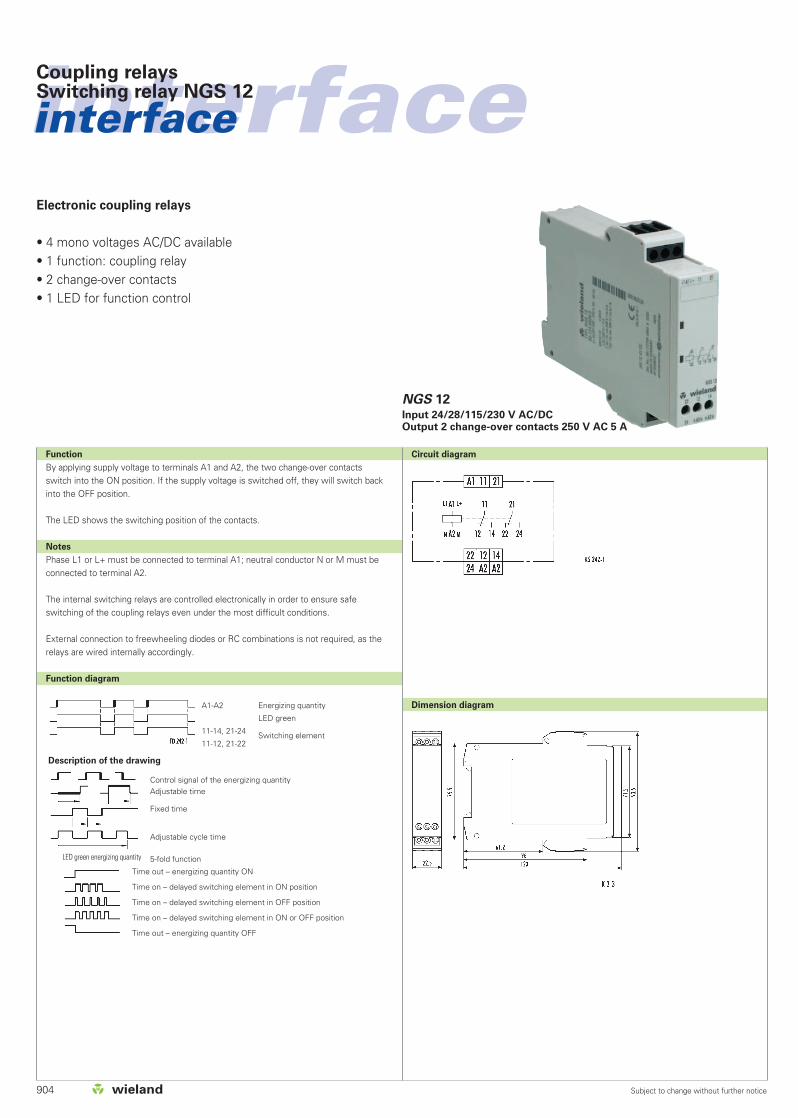
Electronic coupling relays
• 4 mono voltages AC/DC available• 1 function: coupling relay• 2 change-over contacts• 1 LED for function control
Function
By applying supply voltage to terminals A1 and A2, the two change-over contactsswitch into the ON position. If the supply voltage is switched off, they will switch backinto the OFF position.
The LED shows the switching position of the contacts.
Notes
Phase L1 or L+ must be connected to terminal A1; neutral conductor N or M must beconnected to terminal A2.
The internal switching relays are controlled electronically in order to ensure safeswitching of the coupling relays even under the most difficult conditions.
External connection to freewheeling diodes or RC combinations is not required, as therelays are wired internally accordingly.
Function diagram
Circuit diagram
Dimension diagram
interfaceinterfaceCoupling relaysSwitching relay NGS 12
Description of the drawing
Control signal of the energizing quantityAdjustable time
Fixed time
Adjustable cycle time
5-fold functionLED green energizing quantity
A1-A2 Energizing quantity
LED green
11-14, 21-24 Switching element11-12, 21-22
Time out – energizing quantity ON
Time on – delayed switching element in ON position
Time on – delayed switching element in OFF position
Time on – delayed switching element in ON or OFF position
Time out – energizing quantity OFF
NGS 12Input 24/28/115/230 V AC/DCOutput 2 change-over contacts 250 V AC 5 A

905
interfaceCoupling relaysSwitching relay NGS 12
Subject to change without further notice
NGS 12
EN 618122-1:1999-08Item 2.1: switching relays1 LED greenFD 242-1
AC/DC AC/DC AC/DC AC/DC24 V 28 V 110 – 127 V 220 – 240 V1.1 VA / 1.0 W 1.2 VA / 1.0 W 1.7 VA / 1.4 W 1.9 VA / 1.6 W1.1 VA / 1.0 W 1.2 VA / 1.0 W 1.7 VA / 1.4 W 2.0 VA / 1.7 W1.0 W 1.1 W 1.1 W 1.6 W0.3 A / 0.5 ms 0.3 A / 0.5 ms 0.3 A / 0.2 ms 0.2 A / 0.1 ms80 – 110 %50 – 60 Hz ± 5 %≥ 15 % UN; permissible line capacity 0.2 µFA1–A2 yesA1–A2 no
2 change-over contactsAg with 2 to 5 µm AuAC/DC 250 V5 AAC/DC 15 VAC-15 Ue AC 230 V, Ie 3 ADC-13 Ue DC 24 V, Ie 2 A≤ 3600 switching cycles/h30x106 switching cycles0.12 x 106 switching cycles AC-1510 ms / 13 ms
according to IEC 60664-13 outside, 2 insideIII250 VIP 40/ IP 20–25 – +60°CK 3-3KS 242-11 x 0.2 – 6 or 2 x 0.2 – 2.5 mm2
1 x 0.4 – 4 or 2 x 0.2 – 1.5 mm2
0.12 kg––
Type
NGS 12Part No. Std. Pack
R2.154.0030.0 1R2.154.0040.0 1R2.154.0020.0 1R2.154.0010.0 1
Technical data
Product standard
Function type according to IEC 60050Function controlFunction diagramInput circuit
Rated voltage UN
Rated consumption at 50 HzRated consumption at 60 HzRated consumption DCSwitch-on peakRated voltage limitsRated frequency (fn)Release value of the input voltage (power capacity approx. 150 pF/m)Parallel loads permissibleInternal half-wave rectificationOutput circuit
Contact assignmentContact materialRated operating voltageRating for continuous current limit lthMinimal contact voltageApplication category according to EN 60947-5-1
Permissible switching frequencyMechanical lifeElectrical life 20/2 A, AC 250 V, cos ϕ = 0.3Response time / release time at excitation of A1-A2Other data
Creepage distances and clearancesDegree of pollutionOvervoltage categoryRated voltage
Degree of protection according to IEC 60529 housing/terminalsAmbient temperature, Operating rangeDimension diagram (housing)Circuit diagram of the terminalsWire range stranded or solid
stranded with ferrulesWeightAccessoriesApprovals
Overview of the devices/Part numbers
Delay
––––
Rated voltage
AC/DC 24 V 50 – 60 HzAC/DC 28 V 50 – 60 HzAC/DC 220 – 240 V 50 – 60 HzAC/DC 110 – 127 V 50 – 60 Hz

906 Subject to change without further notice
interfaceinterfaceCoupling relaysSelection by function – Solid-state relays
80.0
20.4
100.0
fl
are-
24V
DC
/48V
DC
-0,5
A
80.0
20.4
101.0
fl
are-
24V
DC
/48V
DC
-2A
80.0
20.4
102.0
fl
are-
115V
/48V
DC
-0,5
A
80.0
20.4
103.0
fl
are-
230V
AC
/48V
DC
-0,5
A
80.0
20.4
150.0
fl
are-
24V
DC
/230V
AC
-0,5
A
80.0
20.2
003.0
W
RS
-SS
DC
-60V
3A
80.0
20.2
004.0
W
RS
-SS
DC
-60V
5A
80.0
20.2
001.0
W
RS
-SS
AC
1-2
50V
4A
80.0
20.0
004.0
W
RS
-SS
AC
1-2
50V
6A
910 910 910 911 911 914 914 915 915
• • • • ••
••
•• • • • • • •
••
• • ••
••
••
•
PART NUMBER
CATALOG PAGE
HOUSING
(W x H x D in mm)
INPUT CIRCUIT1)
OUTPUT CIRCUIT2)
6.2 x 89 x 7012.5 x 80 x 5612.5 x 80 x 5912.5 x 80 x 6425.6 x 80 x 70+24 V DC230 V AC115 V AC/DC48 V DC; 0.5 A48 V DC; 2 A60 V DC; 3 A60 V DC; 5 A230 V AC; 0.5 A250 V AC; 4 A250 V AC; 6 A
1) = See data sheet for detailed specification

907Subject to change without further notice
interfaceCoupling relaysSelection by function – Pluggable solid-state relays
M-P
B 8
SG
87.2
20.1
553.3
M-P
B 4
SG
87.2
20.1
453.3
M-P
B 8
SP
87.2
20.0
853.3
M-P
B 4
SP
87.2
20.0
753.3
M-P
B 1
SR
87.2
20.1
353.3
Catalog page
920
920
921
921
922
1) = See the data sheet for detailed specification
Module base
Type/Part No.
Catalog page
26 x 96 x 70.370 x 96 x 70.3138 x 96 x 70.3
+24 V DC+24 V DCmax. 32 V DC / 32 mA240 V AC/DC+24 V DCmax. 32 V DC / 32 mA3-32 V DC24-280 V AC / 3 A3-32 V DC3-60 V DC / 3 A3-32 V DC3-60 V DC / 3 A
Housing
(W x H x D in mm)
Input circuit1)
Auxiliary supply voltageOutput circuit1)
Input circuit1)
Auxiliary supply voltageOutput circuit1)
Input circuit1)
Output circuit1)
Input circuit1)
Output circuit1)
Input circuit1)
Output circuit1)
Solid-state relays
Type/Part No.
M-IDC 24 AZ5.580.8100.0
M-IAC 24Z5.580.7800.0
OAC 3-32 V/24-280 VZ8.000.0156.9ODC 3-32 V/3-60 VZ8.000.0169.8ODC 3-32 V/3-200 VZ8.000.0169.9
918 918 918 919 919
•• •
• •
• • •
• • •
• • • • •
• • • • •
• • • • •

908
interfaceinterface

interface
Subject to change without further notice
Coupling relaysGeneral information – Solid-state relays
909
Wiring diagram of DC input
Wiring diagram of 2 wire output
Wiring diagram of 3 wire output
Wiring diagram of AC output
Wiring diagram of AC input
Wiring diagram of AC/DC input
Neu
tral
switc
h Rload
RLast
Wieland solid-state relay modules, thepowerful addition
Solid-state relays are used in the sameway as electromechanical relays as aconnecting element between field devicesand electronic control and signallingequipment. These modules can offeradditional functionalities to the switchingtasks that are required during processing.The core characteristics of the solid-staterelays are:
❐ High switching frequencies up toseveral kHz
❐ Almost unlimited service life due tolack of mechanics
❐ High tolerance to vibration and impulseloads
❐ Bounce-free and noise-free switching
❐ Control power in the lower mW range
Wieland offers a full range of solid-staterelay modules with the properties outlinedabove. Depending on the required applications, a superior selection of relaymodules are available with variousoperating voltages, output arrangementsand housings.
Product ranges:
flare, solid-state relays with an overallwidth of 6.2 mm with input voltages of24 V DC up to 230 V AC and switchingcurrents up to 2 A.
WRS, solid-state relays in a mountingbase with input voltages of 24 V DC up to 230 V AC and switching currents up to6 A.
M-PB, pluggable, one- to eight-channel solid-state relays in a mounting base withinput voltages of 24 V DC up to 230 V ACand switching currents up to 3 A.
Overview of technical data
Input circuit/control side
Wieland solid-state relays can be controlledwith direct or alternating voltage, dependingon their type. Each of the modules containsa suppression circuit against polarityreversal and an LED for status display inthe input circuit.
To ensure safe operation of the relay theresidual voltage in the control circuit mustnot exceed 5% DC or 15% AC of thisoperating voltage as specified in VDE0435.
Output circuit/loadside
A solid-state relay for either DC or ACloads can be selected depending on theapplication. Also with DC outputs thereare 2 types of connection available.
❐ 2 wire output
❐ 3 wire output, with negative switching
To guarantee error-free operation it isimportant to select a relay with a ratingthat meets the voltage and currentrequirement and also to add a protectivecircuit to the output as shown in thewiring diagram above – such as a varistoror RC element.
If a solid-state relay is operated with aninductive load, the load must be equippedwith a protective suppression circuit suchas a free-wheeling diode. In all cases, itmust be ensured that the protection levelof the protective device lies below therespective off-state voltage of the relay.
Solid-state relays for the AC loadsincorporate a triac as the switchingelement. A triac is a zero voltage switchand is used to avoid high inrush and backEMF peaks by connecting the load at zerovoltage and disconnecting the load at zerocurrent.
As for DC loads, care should be taken thatthe protection level of the protectivemeasures lies below the off-state voltageof the Triac.

Subject to change without further notice
interfaceinterfaceCoupling relaysSolid-state relays
910
Dimensions (mm): W x H x D6.2 x 89 x 70
Description
24 V DC, 500 mA spring clamp connection
24 V DC, 2 A spring clamp connection
115 V AC/DC spring clamp connection
Control side
Nominal input voltageVoltage range “ON”Voltage range “OFF”Power consumptionStatus displayLoad side
Nominal output voltageMin. switching voltageMax. switching voltageMin. switching currentMax. switching currentOn-state voltagePick-up delayRelease delaySwitching frequency (resistive load)Suppression circuitGeneral data
Rated voltageIsolation voltage of input/outputOvervoltage categoryDegree of pollutionAmbient temperatureStorage temperatureProtection type/mounting railStandards/specificationsEmitted interference/interference immunityWire range of screw terminalWire range of spring-clamp terminal
fine-strandedsolid
CSA EX approval in range
Accessories
Pluggable jumper (Umax = 50 V, Imax = 2 A)8 digit marking tag, unmarked, 60 pcs.
flare-24 V DCInput 24 V DCOutput 48 V DC 0.5/2A (SPST, N.O.)
Approvals: qwh
flare-115 V AC/DCInput 115 V AC/DCVOutput 48 V DC 0.5 A
Approvals: qwh
Overall width: 6.2 mm
Type Part No. Std. Packflare-24VDC/48VDC-0,5A 80.020.4100.0 10flare-24VDC/48VDC-2A 80.020.4101.0 10
500 mA 2 A
24 V DC 24 V DC10 V...53 V DC 10 V...53 V DC0 V...5 V DC 0 V...5 V DCca. 6 mA ca. 7 mALED yellow LED yellow
48 V DC 48 V DC4.4 V DC 4.4 V DC53 V DC 53 V DC0.1 mA 1 mA500 mA 2 A1.2 V DC 0.3 V DC0,05 ms 1 ms0.2 ms 5 ms500 Hz 5 HzArc suppression diode Arc suppression diode
3.75 kV / 2.5 kVIII20 °C – +50 °C (Derating)–40 °C – +55 °CIP 20 / TS 35VDE 0160; VDE 0106 T101EN 61000-6-3; EN 61000-6-2–
0.25 mm2 – 1.5 mm2
0.25 mm2 – 2.5 mm2
Class I, Division 2, Groups A, B, C and D
Part No. Std. PackZ8.000.0200.8 10Z4.242.5153.0 10
Type Part No. Std. Pack
flare 115V/48VDC-0,5A 80.020.4102.0 10
115 V AC/DC70 V...122 V AC/DC0 V...30 V AC / 40 V DCca. 3 mALED yellow
48 V DC4.5 V DC53 V DC0.1 mA500 mA1.2 V DC30 ms20 ms10 HzVaristor
3.75 kVIII20 °C – +50 °C (Derating)–40 °C – +55 °CIP 20 / TS 35VDE 0160; VDE 0106 T101EN 61000-6-3; EN 61000-6-2–
0.25 mm2 – 1.5 mm2
0.25 mm2 – 2.5 mm2
Class I, Division 2, Groups A, B, C and D
Part No. Std. PackZ8.000.0200.8 10Z4.242.5153.0 10

interface
Subject to change without further notice
Coupling relaysSolid-state relays
911
Type Part No. Std. Pack
flare-230VAC/48VDC-0,5A 80.020.4103.0 10
230 V AC90...250 V AC0...40 V ACca. 7.5 mALED yellow
48 V DC4.4 V DC53 V DC0.1 mA500 mA1.2 V DC25 ms25 ms10 HzArc suppression diode
3.75 kVIII20 °C – 50 °C–40 °C – +55 °CIP 20 / TS 35VDE 0160; VDE 0106 T101EN 61000-6-3; EN 61000-6-2–
0.25 mm2 – 1.5 mm2
0.25 mm2 – 2.5 mm2
Class I, Division 2, Groups A, B, C and D
Part No. Std. PackZ8.000.0200.8 10Z4.242.5153.0 10
Type Part No. Std. Packflare-24VDC/230VAC-0,5A 80.020.4150.0 10
24 V DC10 V...53 V DC0 V...5 V DCca. 6 mALED yellow
230 V AC12 V AC250 V AC0.1 mA500 mA1.5 V AC10 ms10 ms20 HzArc suppression diode
2.5 kVIII20 °C – 50 °C–40 °C – +55 °CIP 20 / TS 35VDE 0160; VDE 0106 T101EN 61000-6-3; EN 61000-6-2–
0.25 mm2 – 1.5 mm2
0.25 mm2 – 2.5 mm2
Class I, Division 2, Groups A, B, C and D
Part No. Std. PackZ8.000.0200.8 10Z4.242.5153.0 10
Dimensions (mm): W x H x D6.2 x 89 x 70
Overall width: 6.2 mm
flare-230 V AC Input 230 V AC Output 48 V DC 0.5 A
Approvals: qwh
flare-24 V DC Input 24 V DC Output 230 V AC 0.5 A
Approvals: qwhDescription
24 V DC, 500 mA spring clamp connection
230 V AC spring clamp connection
Control side
Nominal input voltageVoltage range “ON”Voltage range “OFF”Power consumptionStatus displayLoad side
Nominal output voltageMin. switching voltageMax. switching voltageMin. switching currentMax. switching currentOn-state voltagePick-up delayRelease delaySwitching frequency (resistive load)Minimum selectable currentSuppression circuitGeneral data
Rated voltageIsolation voltage of input/outputOvervoltage categoryDegree of pollutionAmbient temperatureStorage temperatureProtection type/mounting railStandards/specificationsEmitted interference/interference immunityWire range of screw terminalWire range of spring-clamp terminal
fine-strandedsolid
CSA EX approval in range
Accessories
Pluggable jumper (Umax = 50 V, Imax = 2 A)8 digit marking tag, unmarked, 60 pcs.

Subject to change without further notice
interfaceinterfaceCoupling relaysSolid-state relays
912
Circuit diagrams: flare – solid-state relays
24 V/48 V DC; 500 mA; 2 A 115 V AC/DC / 48 V DC; 500 mA
Derating: solid-state relays
115V AC/DC / 48 V DC; 500 mA230 V AC / 48 V DC; 500 mA24 V DC / 230 V AC; 500 mA24VDC/48VDC-0,5A
230 V AC / 48 V DC; 500 mA 24 V DC / 230 V AC; 500 mA
0,5
0,4
0,3
0,2
0,1
0,50,5
10 20 30 40 50
0,5
0,4
0,3
0,2
0,1
0,50,5
10 20 30 40 50

interface
Subject to change without further notice
Coupling relaysSolid-state relays
913
Dimensions of flare relays
Housing with spring clamp terminals

Subject to change without further notice
interfaceinterfaceCoupling relaysSolid-state relays
914
Type Part No. Std. PackWRS-SSDC-60V3A 80.020.2003.0 10
24 V DC +10%/–15%16 mA0.4 W20 relays
24 V DC60 V DC3 V DC1.5 V DC at Irated
3 A DC (Derating)20 mA5 A DC (1 sec.)1 mA at 60 V DC–Z-Diode 68 V / 5 W100 µs1 kHz4 k Veff.
8 pF
–20 °C...+50 °C (Derating)–25 °C...+85°CTS 32 or TS 35
0.5 mm2 – 2.5 mm2 / 0.5 mm2 – 4 mm2
horizontal
Z8.000.0103.4 10
Type Part No. Std. PackWRS-SSDC-60V5A 80.020.2004.0 10
24 V DC +10%/–15%16 mA0.4 W20 relays
24 V DC60 V DC3 V DC0.5 V DC5 A DC20 mA60 A DC (1 ms)1 µA DCFFZ-Diode 68 V / 5 W1 ms100 Hz2.5 kVeff.
15 pF
–20 °C...+50 °C (Derating)–25 °C...+85°CTS 32 or TS 35
0.5 mm2 – 2.5 mm2 / 0.5 mm2 – 4 mm2
horizontal
Z8.000.0103.4 10
Description
Wieland relay system
Coil circuit
Operating voltageNominal input current per inputNominal input capacityParallel connection of maxSwitching characteristics
Nominal switching voltageMaximum switching voltageMinimum switching voltageEffective on-state voltageMaximum effective currentMinimum effective currentMaximum impulse currentMaximum residual currentFusing, note I2t valueInternal Suppression circuitMaximum pick-up/release delayMaximum switching frequencyIsolation voltage of input/outputCapacity of input/outputOvervoltage categoryDegree of pollutionAmbient temperatureStorage temperatureMounting railStandards/specificationsEmitted interference/interference immunityWire range, fine-stranded/solidLocation of mounting rail
Accessories
Pluggable jumper
Dimensions (mm): W x H x D
WRS-SSDC Input 24 V DC; output 60 V DC 3 A,
2 wire output
Approvals: *Ew12.5 x 80 x 64
WRS-SSDC Input 24 V DC; output 60 V DC 5 A
2 wire output
Approvals: *Ew12.5 x 80 x 59
– 24 V input signals– 2.5-kV separation between I/O at a creepage and
clearance distance of 8 mm

interface
Subject to change without further notice
Coupling relaysSolid-state relays
915
Type Part No. Std. PackWRS-SSAC1-250 V4A 80.020.2001.0 10
24 V DC +15%/–15%20 mA0.5 W20 relays
250 V AC280 V AC48 V AC1200 Vs500 V/µs1.4 V4 A AC60 mA250 A AC (20 ms)0.1 mA > 0.5yes260 A2sFF
10 ms15 Hz4 kVeff.
10 pF
–25 °C...+50 °C (Derating)–25 °C...+85°CTS 32 or TS 35
0.5 mm2 – 2.5 mm2 / 0.5 mm2 – 4 mm2
horizontal
Z8.000.0103.4 10
Type Part No. Std. PackWRS-SSAC1-250 V6A 80.020.0004.0 5
24 V DC +15%/–15%15 mA0.4 W20 relays
24 V – 250 V AC250 V AC24 V AC600 Vs500 V/µs1.6 V6 A AC60 mA10 A AC0.1 mAeff.
> 0.5yes260 A2sFFVaristor10 ms15 Hz4 kVeff.
10 pF
–25 °C...+50 °C (Derating)–25 °C...+85°CTS 32 or TS 35
0.5 mm2 – 2.5 mm2 / 0.5 mm2 – 4 mm2
horizontal
Z8.000.0103.4 10
Description
Wieland relay system
Coil circuit
Operating voltageNominal input currentNominal input capacityParallel connection of maxSwitching characteristics
Nominal switching voltageMaximum switching voltageMinimum switching voltagePeak off-state voltageCritical rate of rise of voltageEffective on-state voltageMaximum effective currentMinimum effective currentMaximum impulse currentMaximum residual currentPower factor �Zero sequence voltage switchI2t valueFusing, note I2t valueInternal Suppression circuitMaximum pick-up/release delayMaximum switching frequencyIsolation voltage of input/outputCapacity of input/outputOvervoltage categoryDegree of pollutionAmbient temperatureStorage temperatureMounting railStandards/specificationsEmitted interference/interference immunityWire range, fine-stranded/solidLocation of mounting rail
Accessories
Pluggable jumper
Dimensions (mm): W x H x D
WRS-SSAC1 Input 24 V DC; output 250 V AC 4 A
2 wire output
Approvals: Ew12.5 x 80 x 56
WRS-SSAC1 Input 24 V DC; output 250 V AC 6 A
2 wire output
Ew25.6 x 80 x 70

Subject to change without further notice
interfaceinterfaceCoupling relaysSolid-state relays
916
WRS solid-state relay
WRS-SSDC-60 V 3 ACircuit diagram WRS-SSDC-60 V 5 A
Derating
o[ C]UT
[A]LI
605040302010
4
3
2
1
5
Dimensions
80.
5963,5
66,5
DeratingSolid-state relay WRS-SSDC 60V 3A
a = side by side without spacingb = side by side with spacing
≥ 20 mm

interface
Subject to change without further notice
Coupling relaysSolid-state relays
917
WRS-SSAC1-250 V 4 ACircuit diagram WRS-SSAC1-250 V 6 A
Derating
Dimensions
DeratingAC 1-phase
a = side by side without spacingb = side by side with spacing
≥ 20 mm

Subject to change without further notice
interfaceinterfaceCoupling relaysPluggable solid-state relays, module bases
918
Type Part No. Std. Pack
M-PB 4 SP 87.220.0753.3 1M-PB 8 SP 87.220.0853.3 1
+
2 V–30 °C...+40 °C–25 °C...+85 °C8 relay, 10 pole5 x 20 mmmax 1.05 mm0.5 mm2 – 2.5 mm2 / 0.5 mm2 – 4 mm2
horizontal
ODC 3–32 V / 3–60 V Z8.000.0169.8 10ODC 3–32 V / 3–200 V Z8.000.0169.9 10OAC 3–32 V / 24–280 V Z8.000.0156.9 10
Type Part No. Std. PackM-PB 1 SR 87.220.1353.3 2
+ / –+ / –
2 V–30 °C...+40 °C–25 °C...+85 °C–5 x 20 mmmax 1.05 mm0.5 mm2 – 2.5 mm2 / 0.5 mm2 – 4 mm2
TS 32 or TS 35horizontal
M-IDC24 Z5.580.8100.0 10M-IAC24 Z5.580.7800.0 10
ODC 3–32 V / 3–60 V Z8.000.0169.8 10ODC 3–32 V / 3–200 V Z8.000.0169.9 10OAC 3–32 V / 24–280 V Z8.000.0156.9 10
Description
1 relay module bases
4 relay module bases
8 relay module bases
Switching variations
Input with positive/negative switchingOutput with positive/negative switching
Notice: Please allow for the voltage drop at the LED
Switching characteristics
See technical data of input/output relayson pages 920 to 922 General data
Voltage drop at the LEDAmbient temperatureStorage temperatureIDC header DIN 41651Miniature fuse holderWire diameter of solid-state relay connectionWire range, fine-stranded/solidMounting railLocation of mounting rail
Accessories
Solid-state relay input (see page 920)Solid-state relay input (see page 920)
Solid-state relay output (see page 921)Solid-state relay output (see page 922)Solid-state relay output (see page 921)
Dimensions (mm): W x H x D
The module bases are supplied without solid-staterelays or miniature fuses
M-PB 1 SRModule base 1 relay26 x 96 x 70.3
Module bases for solid-state relays– 1 relay– 4 relay– 8 relay
M-PB 4/8 SPModule base 4/8 relays70/138 x 96 x 70.3

interface
Subject to change without further notice
Coupling relaysPluggable solid-state relays, module bases
919
Type Part No. Std. Pack
M-PB 4 SG 87.220.1453.3 1M-PB 8 SG 87.220.1553.3 1
–+ / –
2 V–30 °C...+40 °C–25 °C...+85 °C–5 x 20 mmmax 1.05 mm0.5 mm2 – 2.5 mm2 / 0.5 mm2 – 4 mm2
TS 32 or TS 35horizontal
M-IDC24 Z5.580.8100.0 10M-IAC24 Z5.580.7800.0 10
ODC 3–32 V / 3–60 V Z8.000.0169.8 10ODC 3–32 V / 3–200 V Z8.000.0169.9 10OAC 3–32 V / 24–280 V Z8.000.0156.9 10
Dimensions (mm): W x H x D
The module bases are supplied without solid-staterelays or miniature fuses.
M-PB 4/8 SGModule bases 4/8 relay70/138 x 96 x 70.3
Important notice:
In the case of multiple modules (2 change-over contacts), theoutputs must be supplied from the same phase (e.g. L1)
Description
1 relay module bases
4 relay module bases
8 relay module bases
Coil circuit
Input with positive/negative switchingOutput with positive/negative switching
Notice: Please allow for the voltage drop at the LED
Switching characteristics
See technical data of input/output relayson pages 920 to 922 General data
Voltage drop at the LEDAmbient temperatureStorage temperatureIDC header DIN 41651Miniature fuse holderWire diameter of solid-state relay connectionWire range, fine-stranded/solidMounting railLocation of mounting rail
Accessories
Solid-state relay input (see page 920)Solid-state relay input (see page 920)
Solid-state relay output (see page 921)Solid-state relay output (see page 922)Solid-state relay output (see page 921)

Subject to change without further notice
interfaceinterfaceCoupling relaysPluggable solid-state relays, modules
920
Description
Solid-state relay
Pin base input
Pin base output
Coil circuit
Nominal operating voltageMaximum operating voltageMinimum operating voltageNominal input currentBreaking currentResistance
Maximum voltage without reaction at outputMaximum current without reaction at outputSwitching characteristics
Nominal switching voltageMaximum switching voltageMinimum switching voltageMaximum currentLeakage currentLogic voltageLogic currentLogic leakage currentLogic voltage dropMaximum pick-up/release delayMaximum switching frequencyMains frequencyIsolation voltage of input/outputCapacity of input/outputOvervoltage categoryDegree of pollutionAmbient temperatureStorage temperature
Standards/specificationsEmitted interference/interference immunity
Accessories
Pin base
Type Part No. Std. PackM-IAC 24 A Z5.580.7800.0 10
240 V AC280 V AC/DC180 V AC/DC5 mA AC1.5 mA AC75 k�
50 V AC/DC2 mA AC
24 V DC30 V DC20 V DC16 mA DC10 µA DC30 V DC50 mA DC10 µA DC200 mA DC20 ms / 30 ms10 Hz47–63 Hz4 kVeff. (1 sec.)8 pF
–30 °C...+80 °C–40 °C...+100 °C
See pin base on page 918 and 919
Type Part No. Std. PackM-IDC 24 Z5.580.8100.0 10
24 V DC32 V DC3.3 V DC34 mA1 mA DC1 k�
2 V DC1.5 mA DC
24 V DC30 V DC20 V DC16 mA DC10 µA DC30 V DC50 mA DC10 µA DC100 mA DC1 ms / 1 ms1 kHz–4 kVeff. (1sec.)8 pF
–30 °C...+80 °C–40 °C...+100 °C
See pin base on page 918 and 919
Dimensions (mm): W x H x D10.2 x 26.3 x 43.2
M-IAC-24 A Input 240 V AC; output 24 V DC 16 mA
M-IDC-24 Input 24 V DC; output 32 V DV 32 mA
Integration of LED indicator possibleIntegration of fine fuse possible

interface
Subject to change without further notice
Coupling relaysPluggable solid-state relays, modules
921
Type Part No. Std. PackOAC 3-32 V/24-280 V Z8.000.0156.9 10
3 – 32 V DC1 – 22 mA3 V DC1 V DC32 V DC1.5 k�
48 – 256 Veff V AC650 Vs100 V/µs1.6 V5 A / 3 A (AC1 / AC3)50 mA90 As5 mA≥ 0.5yes42 A2sFF 2.5 AF 3.15 A10 ms–4 kVeff.
8 pF
–20 °C...+70 °C (Derating)–40 °C...+100 °C
See pin base on page 918 and 919
Type Part No. Std. PackODC 3-32 V/3-60 V Z8.000.0169.8 10
3 – 32 V DC3 – 32 mA3 V DC1 V DC6 V DC1 k�
3 – 60 V DC60 V DC–1.5 V3 A DC (DC 13), (5 A / 1 sec)1 mA–1 mA–––FF 2.5 AF 3.15 A100 µs / 1 ms1 kHz4 kVeff.
8 pF
–40 °C...+50 °C (Derating)–40 °C...+100 °C
See pin base on page 918 and 919
Dimensions (mm): W x H x D
OAC 3-32 V Input 3-32 V DC; output 230 V AC 3 A
10.5 x 25.4 x 43
Integration of LED indicator possibleIntegration of fine fuse possible
ODC 3-32 V Input 3-32 V DC; output 60 V DC 3 A
10.5 x 25.4 x 43Description
Solid-state relay
Coil circuit
Operating voltageNominal input currentMinimum closing voltageMaximum opening voltageMaximum reverse voltageResistanceSwitching behaviour
Switching voltagePeak off-state voltageCritical rate of rise of voltageMaximum effective on-state voltageMaximum effective current Minimum effective currentMaximum impulse current (20 ms)Maximum leakage currentPower factor �Zero sequence voltage switchI2t valueFusing of solid-state relayFusing of load circuitMaximum pick-up/release delayMaximum switching frequencyIsolation voltage of input/outputCapacity of input/outputOvervoltage categoryDegree of pollutionAmbient temperatureStorage temperature
Standards/specificationsEmitted interference/interference immunity
Accessories
Pin base

Subject to change without further notice
interfaceinterfaceCoupling relaysPluggable solid-state relays, modules
922
Type Part No. Std. PackODC 3-32 V/3-200 V Z8.000.0169.9 10
3–32 V DC3–32 mA3 V DC1 V DC6 V DC1 k�
3–200 V DC200 V DC–1.5 V1 A (DC13); 2 A (1 sec)1 mA–1 mA–––FF 2.5 AF 1.25 A100 µs / 1 ms1 kHz4 kVeff.
8 pF
–40 °C...+50 °C (Derating)–40 °C...+100 °C
See pin base on page 918 and 919
Description
Solid-state relay
Coil circuit
Operating voltageNominal input current per inputMinimum closing voltageMaximum opening voltageMaximum reverse voltageResistance
Switching characteristics
Nominal switching voltagePeak off-state voltageCritical rate of rise of voltageMaximum effective on-state voltageMaximum effective currentMinimum effective currentMaximum impulse currentMaximum residual currentPower factor �Zero sequence voltage switchI2t valueFusing, note I2t value
Maximum pick-up/release delayMaximum switching frequencyIsolation voltage of input/outputCapacity of input/outputOvervoltage categoryDegree of pollutionAmbient temperatureStorage temperatureStandards/specificationsEmitted interference/interference immunity
Accessories
Pin base
Dimensions (mm): W x H x D10.2 x 26.3 x 43.2
ODC 3-32 V Input 3-32 V DC; output 200 V DC 1 A

interface
Subject to change without further notice
Coupling relaysPluggable solid-state relays, modules
923
Circuit diagrams: M-PB module bases
M-PB 4/8 SPM-PB 1SR M-PB 4/8 SG
Circuit diagrams: M-PB solid-state relays Dimensions
M-IDC 24M-IAC 24 A M-IAC 24 A / M-IDC 24 A
Dimensions of module bases
I/O-Module8
I/O-Module1

Subject to change without further notice
interfaceinterfaceCoupling relaysPluggable solid-state relays, modules
924
Circuit diagrams + derating: M-PB solid-state relays
ODC 3–32 V/3–60 V ODC 3–32 V/3–200 VOAC 3–32 V/24–280 V
Output 60 V DC Output 200 V DCOutput 230 V AC
Dimensions
OAC 3–32 V/24–280 V
0,5
0,4
0,3
0,2
0,1
0,50,5
10 20 30 40 50 60 70
Derating

interface
925