Embed Size (px)
Citation preview

Installer’s Guide Keypad Installer’s Guide Keypad Installer’s Guide Keypad Installer’s Guide Keypad Installer’s Guide Keypad Installer’s Guide Keypad Installer’s Guide
Keypad Installer’s Guide Keypad Installer’s Guide Keypad Installer’s Guide Keypad Installer’s Guide Keypad Installer’s Guide Keypad Installer’s Guide Keypad Installer’s
Guide Keypad Installer’s Guide Keypad Installer’s Guide Keypad Installer’s Guide Keypad Installer’s Guide Keypad Installer’s Guide Keypad Installer’s Guide Keypad
Installer’s Guide Keypad Installer’s Guide Keypad Installer’s Guide Keypad Installer’s Guide Keypad Installer’s Guide Keypad Installer’s Guide Keypad Installer’s Guide
Keypad Installer’s Guide Keypad Installer’s Guide Keypad Installer’s Guide Keypad Installer’s Guide Keypad Installer’s Guide Keypad Installer’s Guide Keypad Installer’s
Guide Keypad Installer’s Guide Keypad Installer’s Guide Keypad Installer’s Guide Keyp
© 201
ad Installer’s Guide Keypad Installer’s Guide Keypad Installer’s Guide Keypad Installer’s Guide Keypad Installer’s Guide Keypad Installer’s Guide Keypad Installer’s
Guide Keypad Installer’s Guide Keypad Installer’s Guide Keypad Installer’s Guide Keypad Installer’s Guide Keypad Installer’s Guide Keypad Installer’s Guide Keypad
Installer’s Guide Keypad Installer’s Guide Keypad Installer’s Guide Keypad Installer’s Guide Keypad Installer’s Guide Keypad Installer’s Guide Keypad Installer’s Guide
Keypad Installer’s Guide Keypad Installer’s Guide Keypad Installer’s Guide Keypad Installer’s Guide Keypad Installer’s Guide Keypad Installer’s Guide Keypad Installer’s
Guide Keypad Installer’s Guide Keypad Installer’s Guide Keypad Installer’s Guide Keypad Installer’s Guide Keypad Installer’s Guide Keypad Installer’s Guide Keypad
Installer’s Guide Keypad Installer’s Guide Keypad Installer’s Guide Keypad Installer’s Guide Keypad Installer’s Guide Keypad Installer’s Guide Keypad Installer’s Guide
Keypad Installer’s
www.visonic.comContact Visonic for further information:[email protected]
INS
TAL
LE
R
GU
ID
E
K e y p a d I n s t a l l e r ' s G u i d e
K P - 2 5 0 P G 2
© 2017 Tyco S
ecurity Products. A
ll rights reserved. KP
-250 PG
2 English Installer G
uide D-306919
INSTALLER GUIDE
1 2
5
3
4 6
7 8 9
10 11 12
13
14
15
16
17 18
22 2423 25
35
26
36
27 29 3130
32 33 34
28
19 20 21
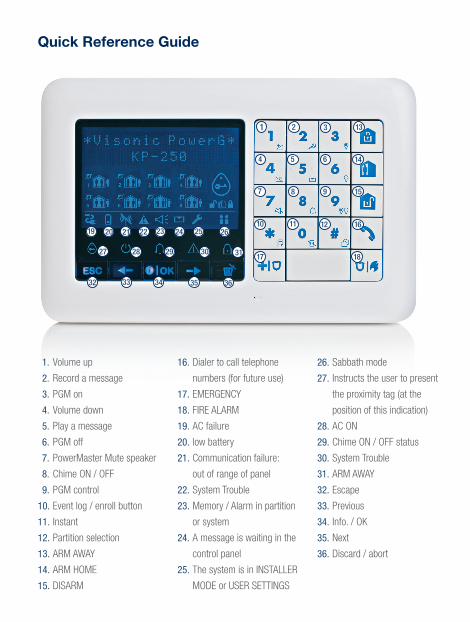
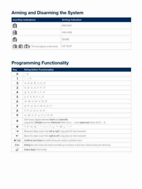
Quick Reference Guide Arming and Disarming the SystemIcon/Key Indications Arming Indication
ARM AWAY
ARM HOME
DISARM
The icons appear consecutively EXIT DELAY
Programming FunctionalityKey String Editor Functionalityl
‘ ‘, ‘0’
‘.’, ‘,’, ‘1’
‘a’, ‘A’, ‘b’, ‘B’, ‘c’, ‘C’, ‘2’
‘d’, ‘D’, ‘e’, ‘E’, ‘f’, ‘F’, ‘3’
‘g’, ‘G’, ‘h’, ‘H’, ‘i’, ‘I’, ‘4’
‘j’, ‘J’, ‘k’, ‘K’, ‘l’, ‘L’, ‘5’
‘m’, ‘M’, ‘n’, ‘N’, ‘o’, ‘O’, ‘6’
‘p’, ‘P’, ‘q’, ‘Q’, ‘r’, ‘R’, ‘s’, ‘S’, ‘7’
‘t’, ‘T’, ‘u’, ‘U’, ‘v’, ‘V’, ‘8’
‘w’, ‘W’, ‘x’, ‘X’, ‘y’, ‘Y’, ‘z’, ‘Z’, ‘9’
Short press: toggles between Insert and overwrite. Long press: Changes between lowercase letters (a,b,c…z) and uppercase letters (A,B,C…Z)
‘!’, ‘#’, ‘%’, ‘&’, ‘’’, ‘*’, ‘+’, ‘-’, ‘/’, ‘=’, ‘^’, ‘@’, ‘ ’, ‘”’, “:”
Moves the digits cursor from left to right. Long press for fast movement
Moves the digits cursor from right to left. Long press for fast movement
Confirms and saves the edited string and reverts to previous menu
Exiting the edit screen and moves one level up to previous or top menu without saving the edit string
Clears digits of the string
1. Volume up
2. Record a message
3. PGM on
4. Volume down
5. Play a message
6. PGM off
7. PowerMaster Mute speaker
8. Chime ON / OFF
9. PGM control
10. Event log / enroll button
11. Instant
12. Partition selection
13. ARM AWAY
14. ARM HOME
15. DISARM
16. Dialer to call telephone
numbers (for future use)
17. EMERGENCY
18. FIRE ALARM
19. AC failure
20. low battery
21. Communication failure:
out of range of panel
22. System Trouble
23. Memory / Alarm in partition
or system
24. A message is waiting in the
control panel
25. The system is in INSTALLER
MODE or USER SETTINGS
26. Sabbath mode
27. Instructs the user to present
the proximity tag (at the
position of this indication)
28. AC ON
29. Chime ON / OFF status
30. System Trouble
31. ARM AWAY
32. Escape
33. Previous
34. Info. / OK
35. Next
36. Discard / abort
1 2
5
3
4 6
7 8 9
10 11 12
13
14
15
16
17 18
22 2423 25
35
26
36
27 29 3130
32 33 34
28
19 20 21
Quick Reference Guide Arming and Disarming the SystemIcon/Key Indications Arming Indication
ARM AWAY
ARM HOME
DISARM
The icons appear consecutively EXIT DELAY
Programming FunctionalityKey String Editor Functionalityl
‘ ‘, ‘0’
‘.’, ‘,’, ‘1’
‘a’, ‘A’, ‘b’, ‘B’, ‘c’, ‘C’, ‘2’
‘d’, ‘D’, ‘e’, ‘E’, ‘f’, ‘F’, ‘3’
‘g’, ‘G’, ‘h’, ‘H’, ‘i’, ‘I’, ‘4’
‘j’, ‘J’, ‘k’, ‘K’, ‘l’, ‘L’, ‘5’
‘m’, ‘M’, ‘n’, ‘N’, ‘o’, ‘O’, ‘6’
‘p’, ‘P’, ‘q’, ‘Q’, ‘r’, ‘R’, ‘s’, ‘S’, ‘7’
‘t’, ‘T’, ‘u’, ‘U’, ‘v’, ‘V’, ‘8’
‘w’, ‘W’, ‘x’, ‘X’, ‘y’, ‘Y’, ‘z’, ‘Z’, ‘9’
Short press: toggles between Insert and overwrite. Long press: Changes between lowercase letters (a,b,c…z) and uppercase letters (A,B,C…Z)
‘!’, ‘#’, ‘%’, ‘&’, ‘’’, ‘*’, ‘+’, ‘-’, ‘/’, ‘=’, ‘^’, ‘@’, ‘ ’, ‘”’, “:”
Moves the digits cursor from left to right. Long press for fast movement
Moves the digits cursor from right to left. Long press for fast movement
Confirms and saves the edited string and reverts to previous menu
Exiting the edit screen and moves one level up to previous or top menu without saving the edit string
Clears digits of the string
1. Volume up
2. Record a message
3. PGM on
4. Volume down
5. Play a message
6. PGM off
7. PowerMaster Mute speaker
8. Chime ON / OFF
9. PGM control
10. Event log / enroll button
11. Instant
12. Partition selection
13. ARM AWAY
14. ARM HOME
15. DISARM
16. Dialer to call telephone
numbers (for future use)
17. EMERGENCY
18. FIRE ALARM
19. AC failure
20. low battery
21. Communication failure:
out of range of panel
22. System Trouble
23. Memory / Alarm in partition
or system
24. A message is waiting in the
control panel
25. The system is in INSTALLER
MODE or USER SETTINGS
26. Sabbath mode
27. Instructs the user to present
the proximity tag (at the
position of this indication)
28. AC ON
29. Chime ON / OFF status
30. System Trouble
31. ARM AWAY
32. Escape
33. Previous
34. Info. / OK
35. Next
36. Discard / abort

KP-250 PG2 Advanced Two-Way Keypad
Installer’s Guide
Table of Contents 1. Introduction ................................................................................................................................................................. 4 2. Installation .................................................................................................................................................................. 4
2.1 Inserting Battery ................................................................................................................................................ 4 2.2 Desktop Installation .......................................................................................................................................... 4 2.3 Wall Mounting ................................................................................................................................................... 5 2.4 Enrollment of the KP-250 PG2 Keypad in PowerMaster-10/30 G2 ................................................................... 5 2.5 Enrollment of the First KP-250 PG2 Keypad in PowerMaster-33 G2 ................................................................ 6 2.6 Configuring the KP-250 PG2 Parameters ......................................................................................................... 7
3. Programming .............................................................................................................................................................. 9 3.1 General Guidance ............................................................................................................................................. 9
3.1.1 Navigation .................................................................................................................................................. 9 3.1.2 Feedback Sounds ...................................................................................................................................... 9
3.2 Entering the "Installer Mode" and Selecting a Menu Option ........................................................................... 10 3.2.1 Entering the "Installer Mode" if "User Permit" is enabled ......................................................................... 11 3.2.2 Selecting options...................................................................................................................................... 11 3.2.3 Exiting the Installer Mode ......................................................................................................................... 11
3.3 Setting Installer Codes .................................................................................................................................... 11 3.3.1 Identical Installer and Master Installer Codes .......................................................................................... 13
3.4 Zones / Devices .............................................................................................................................................. 13 3.4.1 General Guidance & Zones/Devices Menu Options................................................................................. 13 3.4.2 Adding New Wireless Devices or Wired Sensors..................................................................................... 14 3.4.3 Deleting a Device ..................................................................................................................................... 19 3.4.4 Modifying or Reviewing a Device ............................................................................................................. 20 3.4.5 Replacing a Device .................................................................................................................................. 21 3.4.6 Configuring Soak Test Mode ................................................................................................................... 22 3.4.7 Defining Configuration Defaults for "Device Settings" .............................................................................. 23 3.4.8 Updating Devices after Exiting Installer Mode ......................................................................................... 24 3.4.9 KP-250 PG2 Display when PowerMaster Panel is Active ........................................................................ 24
3.5 Control Panel .................................................................................................................................................. 24 3.5.1 General Guidance – "Control Panel" Flow-Chart & Menu Options ........................................................... 24 3.5.2 Configuring Arming/Disarming and Exit/Entry Procedures ....................................................................... 27 3.5.3 Configuring Zones Functionality............................................................................................................... 29 3.5.4 Configuring Alarms & Troubles ................................................................................................................ 30
D-306919 KP-250 PG2 Installer’s Guide 1
3.5.5 Configuring Sirens Functionality .............................................................................................................. 32 3.5.6 Configuring Audible & Visual User Interface ............................................................................................ 33 3.5.7 Configuring Jamming and Supervision (Missing device).......................................................................... 35 3.5.8 Configuring Miscellaneous Features ........................................................................................................ 36
3.6 Communication ............................................................................................................................................... 36 3.6.1 General Guidance – "Communication" Flow-Chart & Menu Options ....................................................... 36 3.6.2 Configuring PSTN (landline phone) Connection ...................................................................................... 40 3.6.3 Configuring GSM-GPRS (IP) - SMS Cellular Connection ........................................................................ 41 3.6.4 Configuring Events Reporting to Monitoring Stations............................................................................... 43 3.6.5 Configuring Events Reporting to Private Users ........................................................................................ 50 3.6.6 Configuring Motion Cameras for Visual Alarm Verification ...................................................................... 50 3.6.7 Configuring Upload / Download Remote Programming Access Permission ............................................ 51 3.6.8 Broadband ............................................................................................................................................... 54
3.7 PGM Output .................................................................................................................................................... 56 3.7.1 General Guidance .................................................................................................................................... 56 3.7.2 Open Collector States .............................................................................................................................. 56 3.7.3 Output Configuration ................................................................................................................................ 56 3.7.4 I/O Configuration ...................................................................................................................................... 56 3.7.5 PGM Connection...................................................................................................................................... 58 3.7.6 Entering Daytime Limits ........................................................................................................................... 58
3.8 Custom Names ............................................................................................................................................... 59 3.8.1 Custom Zone Names ............................................................................................................................... 60 3.8.2 Record Speech ........................................................................................................................................ 62 3.8.3 Voice Box Mode ....................................................................................................................................... 63
3.9 Diagnostics ..................................................................................................................................................... 63 3.9.1 General Guidance – "Diagnostics" Flow-Chart & Menu Options .............................................................. 63 3.9.2 Testing Wireless Devices ......................................................................................................................... 65 3.9.3 Testing the GSM module ......................................................................................................................... 67 3.9.4 Testing the SIM Number .......................................................................................................................... 68 3.9.5 Testing the Broadband/PowerLink Module .............................................................................................. 69
3.10 User Settings ................................................................................................................................................ 70 3.11 Factory Default ............................................................................................................................................. 70 3.12 Serial Number ............................................................................................................................................... 72 3.13 Partitioning .................................................................................................................................................... 72
3.13.1 General Guidance – "Partitioning" Menu ............................................................................................... 73 3.13.2 Enabling / Disabling Partitions ............................................................................................................... 74
3.14 Operation Mode ............................................................................................................................................ 74 3.14.1 General Guidance – "Operation Mode" Menu ........................................................................................ 74 3.14.2 Select Setting ......................................................................................................................................... 74 3.14.3 BS8243 Setup ........................................................................................................................................ 75
2 D-306919 KP-250 PG2 Installer’s Guide
3.14.4 DD243 Setup ......................................................................................................................................... 77 3.14.5 CP01 Setup ........................................................................................................................................... 79 3.14.6 OTHERS SETUP or EN50131 SETUP .................................................................................................. 80
4. Periodic Test by Installer Code ................................................................................................................................. 82 4.1 General Guidance ........................................................................................................................................... 82 4.2 Conducting a Periodic Test ............................................................................................................................. 82
5. Handling System Troubles ....................................................................................................................................... 87 6. Reading the Event Log ............................................................................................................................................. 89 APPENDIX A: Specifications ........................................................................................................................................ 91 APPENDIX B: Working with Partitions .......................................................................................................................... 92
B1. User Interface and Operation ......................................................................................................................... 92 B2. Common Areas .............................................................................................................................................. 92
APPENDIX C: Glossary ................................................................................................................................................ 94 APPENDIX D: Compliance with Standards .................................................................................................................. 97
D-306919 KP-250 PG2 Installer’s Guide 3
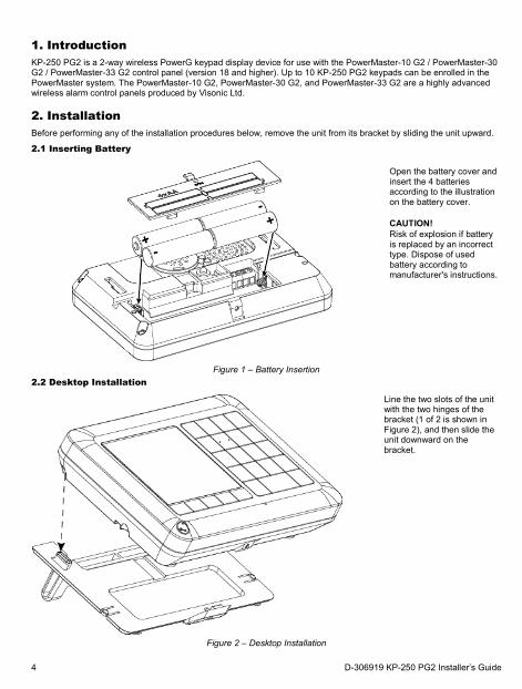
1. Introduction KP-250 PG2 is a 2-way wireless PowerG keypad display device for use with the PowerMaster-10 G2 / PowerMaster-30 G2 / PowerMaster-33 G2 control panel (version 18 and higher). Up to 10 KP-250 PG2 keypads can be enrolled in the PowerMaster system. The PowerMaster-10 G2, PowerMaster-30 G2, and PowerMaster-33 G2 are a highly advanced wireless alarm control panels produced by Visonic Ltd.
2. Installation Before performing any of the installation procedures below, remove the unit from its bracket by sliding the unit upward.
2.1 Inserting Battery
Open the battery cover and insert the 4 batteries according to the illustration on the battery cover.
CAUTION! Risk of explosion if battery is replaced by an incorrect type. Dispose of used battery according to manufacturer's instructions.
Figure 1 – Battery Insertion 2.2 Desktop Installation
Line the two slots of the unit with the two hinges of the bracket (1 of 2 is shown in Figure 2), and then slide the unit downward on the bracket.
Figure 2 – Desktop Installation
4 D-306919 KP-250 PG2 Installer’s Guide
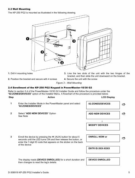
2.3 Wall Mounting The KP-250 PG2 is mounted as illustrated in the following drawing.
1. Drill 4 mounting holes 3. Line the two slots of the unit with the two hinges of the
bracket, and then slide the unit downward on the bracket. 2. Position the bracket and secure with 4 screws 4. Secure the unit with the screw
Figure 3 – Wall Mounting
2.4 Enrollment of the KP-250 PG2 Keypad in PowerMaster-10/30 G2 Refer to section 5.4 of the PowerMaster-10/30 G2 Installer Guide and follow the procedure under the "02:ZONES/DEVICES" option of the Installer Menu. A flowchart of the procedure is provided below. Step Action LCD Display
1 Enter the Installer Mode in the PowerMaster panel and select
“02:ZONES/DEVICES” 02:ZONES/DEVICES
2 Select "ADD NEW DEVICES" Option See Note
ADD NEW DEVICES
MODIFY DEVICES
3 Enroll the device by pressing the (AUX) button for about 5 seconds until the LED turns ON and then release the button, or enter the 7-digit ID code that appears on the sticker on the back of the device
ENROLL NOW or
ENTR ID:XXX-XXXX
The display reads [DEVICE ENROLLED] for a short duration and then changes to read the tag's details
DEVICE ENROLLED
D-306919 KP-250 PG2 Installer’s Guide 5
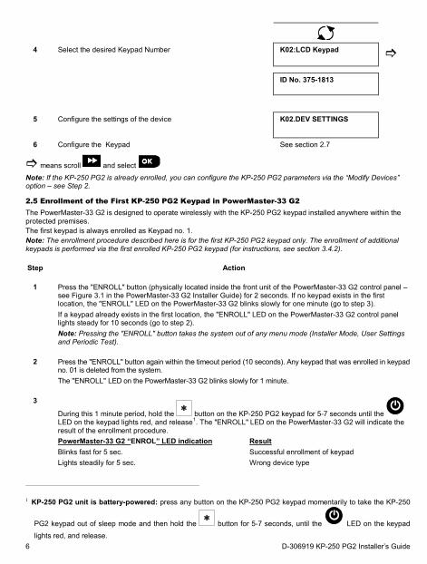
4 Select the desired Keypad Number K02:LCD Keypad
ID No. 375-1813
5 Configure the settings of the device K02.DEV SETTINGS
6 Configure the Keypad See section 2.7
means scroll and select
Note: If the KP-250 PG2 is already enrolled, you can configure the KP-250 PG2 parameters via the “Modify Devices” option – see Step 2.
2.5 Enrollment of the First KP-250 PG2 Keypad in PowerMaster-33 G2 The PowerMaster-33 G2 is designed to operate wirelessly with the KP-250 PG2 keypad installed anywhere within the protected premises. The first keypad is always enrolled as Keypad no. 1. Note: The enrollment procedure described here is for the first KP-250 PG2 keypad only. The enrollment of additional keypads is performed via the first enrolled KP-250 PG2 keypad (for instructions, see section 3.4.2). Step Action
1 Press the "ENROLL" button (physically located inside the front unit of the PowerMaster-33 G2 control panel –
see Figure 3.1 in the PowerMaster-33 G2 Installer Guide) for 2 seconds. If no keypad exists in the first location, the "ENROLL" LED on the PowerMaster-33 G2 blinks slowly for one minute (go to step 3). If a keypad already exists in the first location, the "ENROLL" LED on the PowerMaster-33 G2 control panel lights steady for 10 seconds (go to step 2). Note: Pressing the "ENROLL" button takes the system out of any menu mode (Installer Mode, User Settings and Periodic Test).
2 Press the "ENROLL" button again within the timeout period (10 seconds). Any keypad that was enrolled in keypad
no. 01 is deleted from the system. The "ENROLL" LED on the PowerMaster-33 G2 blinks slowly for 1 minute.
3
During this 1 minute period, hold the button on the KP-250 PG2 keypad for 5-7 seconds until the LED on the keypad lights red, and release1. The "ENROLL" LED on the PowerMaster-33 G2 will indicate the result of the enrollment procedure. PowerMaster-33 G2 “ENROL” LED indication Result Blinks fast for 5 sec. Successful enrollment of keypad Lights steadily for 5 sec. Wrong device type
1 KP-250 PG2 unit is battery-powered: press any button on the KP-250 PG2 keypad momentarily to take the KP-250
PG2 keypad out of sleep mode and then hold the button for 5-7 seconds, until the LED on the keypad lights red, and release.
6 D-306919 KP-250 PG2 Installer’s Guide
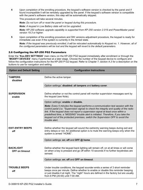
4
Upon completion of the enrolling procedure, the keypad’s software version is checked by the panel and if found incompatible it will be remotely upgraded by the panel. If the keypad’s software version is compatible with the panel’s software version, this step will be automatically skipped. This procedure will take several minutes. Note: Do not turn off or reset the panel or keypad during this procedure. Note: A keypad in Low Battery state will not be upgraded. Note: KP-250 software upgrade capability is supported from KP-250 version 2.019 and PowerMaster panel version 19.3 or higher.
5 Upon completion of the enrolling procedure and SW versions adjustment procedure, the keypad is ready for immediate use even if the system is currently in the Armed state. Note: If the keypad was previously enrolled, it will be relocated automatically to Keypad no. 1. However, all of the configured parameters will be lost and the keypad will revert to the default parameters.
2.6 Configuring the KP-250 PG2 Parameters Enter the “Kxx.DEV SETTINGS” main menu on the KP-250 PG2 keypad immediately after enrollment or through the “MODIFY DEVICES” menu if performed at a later stage. Choose the number of the keypad device to configure and follow the configuration instructions for the KP-250 P-G2 keypad. Refer to Chapter 7; section A.3 for a description on the buttons to use for navigation and setting.
Option and Default Setting Configuration Instructions
TAMPERS disabled
Define the active tamper.
Option settings: disabled; all tampers and battery cover.
SUPERVISION
enable Define whether or not the control panel will monitor supervision messages sent by
the keypad (see Note).
Option settings: enable or disable. Note: Every 5 minutes the keypad performs a communication test session with the control panel (i.e. "Supervision signal) to check the integrity and quality of the radio link. If the keypad does not report a supervision signal at least once within a predefined time, a “MISSING” trouble alert is initiated. Therefore, if you take the keypad out of the protected premises, switch the Supervision OFF to avoid the trouble alert.
EXIT-ENTRY BEEPS
off Define whether the keypad will sound the exit/entry warning beeps during exit and
entry delays or not. An additional option is to mute the warning beeps only when the system is armed “HOME”.
Option settings: on; off and OFF @ home.
BACKLIGHT
OFF on timeout Define whether the keypad back lighting will remain off, on at all times or will come
on when a key is pressed and go off within 10 seconds if no further keystrokes are sensed.
Option settings: on; off and OFF on timeout.
TROUBLE BEEPS
off Under trouble conditions, the keypad sounder emits a series of 3 short reminder
beeps once per minute. Define whether to enable or disable this reminder beeping or just disable it at night. The “night” hours are defined in the factory but are usually from 8 PM (20:00) until 7:00 AM.
D-306919 KP-250 PG2 Installer’s Guide 7
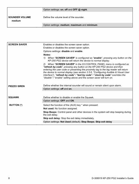
Option settings: on; off and OFF @ night.
SOUNDER VOLUME
medium Define the volume level of the sounder.
Option settings: medium; maximum and minimum
SCREEN SAVER
Enables or disables the screen saver option.
Enables or disables the screen saver option. Options settings: disable and enable. Notes: 1) When "SCREEN SAVER" is configured as "enable", pressing any button on the
KP-250 PG2 device will return the device to normal display. 2) When "SCREEN SAVER" in the 03:CONTROL PANEL menu is configured as "refresh by code", pressing any button on the KP-250 PG2 device and then entering the user code or presenting the proximity tag to the tag reader will return the device to normal display (see section 3.5.6, “Configuring Audible & Visual User Interface”). "refresh by code" / "text by code" / "clock by code" overrides the “disable” / “enable” setting above and the screen saver will turn on.
PIEZZO SIREN
Define whether the internal sounder will sound or remain silent upon alarm. Option settings: off and on.
SQUAWK
Define whether to disable or enable the Squawk. Option settings: OFF and ON.
BUTTON (*)
Select the function of the (AUX) key * when pressed: Not used: No function assigned. Stop Beeps: Control panel and other devices in the system will stop beeping during the exit delay. Skip exit delay: Stop the exit delay immediately. Option settings: Not Used (default); Stop Beeps; Skip exit delay
8 D-306919 KP-250 PG2 Installer’s Guide
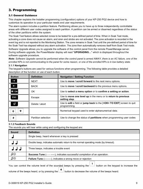
3. Programming 3.1 General Guidance This chapter explains the Installer programming (configuration) options of your KP-250 PG2 device and how to customize its operation to your particular needs end user requirements. The alarm system includes a partition feature. Partitioning allows you to have up to three independently controllable areas with different user codes assigned to each partition. A partition can be armed or disarmed regardless of the status of the other partitions within the system. The Soak Test feature allows selected zones to be tested for a pre-defined period of time. When in Soak Test mode, activating a zone does not cause an alarm, and siren and strobe are not activated. The zone activation is recorded in the event log and is not reported to the Monitoring Station. The zone remains in Soak Test until the pre-defined period of time for the Soak Test has elapsed without any alarm activation. The zone then automatically removes itself from Soak Test mode. Software Upgrade allows you to upgrade the software of the control panel from the remote PowerManage server. During software upgrade, the PowerMaster display will read "UPGRADING…" which is displayed throughout the software upgrade procedure. Note: Software Upgrade cannot be performed when the control panel is armed AWAY, there is an AC failure, one of the enrolled KPs is not communicating to the panel for some reason, or one of the enrolled KPs is in low battery state. 3.1.1 Navigation The keypad's buttons are used for various functions when programming. The following table provides a detailed description of the function or use of each button.
Button Definition Navigation / Setting Function
NEXT Use to move / scroll forward to the next menu options.
BACK Use to move / scroll backward to the previous menu options.
OK Use to select a menu option or to confirm a setting or action.
Escape Use to move one level up in the menu or to return to previous setting step.
Delete / abort Use to edit a field or jump back to the [<OK> TO EXIT] screen to quit programming.
- Numerical keypad used to enter alphanumerical data.
Partition selection Use to change the status of partitions when programming user codes
3.1.2 Feedback Sounds The sounds you will hear while using and configuring the keypad are:
Sound Definition
Single beep, heard whenever a key is pressed
Double beep, indicates automatic return to the normal operating mode (by timeout).
Three beeps, indicates a trouble event
♫ Success Tune (- - - –––), indicates successful completion of an operation.
♫ Failure Tune (–––––), indicates a wrong move or rejection
You can control the volume level of the sounded beeps by pressing the button on the keypad to increase the
volume of the beeps heard, or by pressing the button to decrease the volume of the beeps heard.
D-306919 KP-250 PG2 Installer’s Guide 9
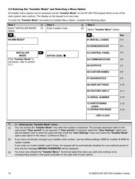
3.2 Entering the "Installer Mode" and Selecting a Menu Option All installer menu options can be accessed via the "Installer Mode" on the KP-250 PG2 keypad which is one of the main system menu options. The display on the keypad is on two rows.
To enter the "Installer Mode" and select an Installer Menu Option, complete the following steps:
Step 1 Step 2 Step 3 Select "INSTALLER MODE" Option
[1] Enter Installer Code [2] Select "Installer Menu" Option
See
HH:MM READY
01:INSTALL CODES
3.3
02:ZONES/DEVICES
3.4
INSTALLER MODE
ENTER CODE:
03:CONTROL PANEL
3.5
If the "Installer Mode" is not shown, refer to section 3.2.1
04:COMMUNICATION
3.6
05:OUTPUTS
3.7
06:CUSTOM NAMES
3.8
07:DIAGNOSTICS
3.9
08:USER SETTINGS
3.10
09:FACTORY DEFLT
3.11
10:SERIAL NUMBER
3.12
12:PARTITIONING enable
3.13
13:OPERATION MODE
3.14
<OK> to Exit
- Entering the "Installer Mode" menu [1] You can access the "Installer Mode" only when the system is disarmed. The process described refers to the
case where "User permit" is not required. If "User permit" is required, select the "User Settings" option and ask the Master User to enter his code and then scroll the "User Settings" menu and select the "Installer Mode" option (last option in the menu). Continue to Step 2.
[2] If you have not already changed your Installer code number, use the default settings: 8888 for installer & 9999 for master installer. If you enter an invalid installer code 5 times, the keypad will be automatically disabled for a pre-defined period of time and the message WRONG PASSWORD will be displayed.
[3] You have now entered the "Installer Menu". Scroll and select the menu you wish and continue to its corresponding section in the guide (indicated on the right side of each option).
10 D-306919 KP-250 PG2 Installer’s Guide
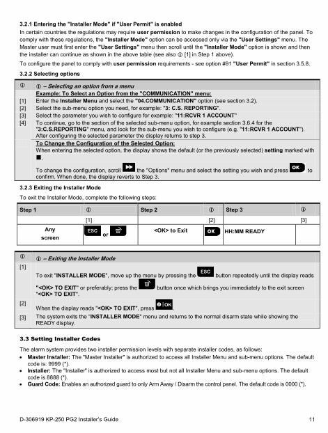
3.2.1 Entering the "Installer Mode" if "User Permit" is enabled In certain countries the regulations may require user permission to make changes in the configuration of the panel. To comply with these regulations, the "Installer Mode" option can be accessed only via the "User Settings" menu. The Master user must first enter the "User Settings" menu then scroll until the "Installer Mode" option is shown and then the installer can continue as shown in the above table (see also [1] in Step 1 above). To configure the panel to comply with user permission requirements - see option #91 "User Permit" in section 3.5.8.
3.2.2 Selecting options
– Selecting an option from a menu
Example: To Select an Option from the "COMMUNICATION" menu: [1] Enter the Installer Menu and select the "04.COMMUNICATION" option (see section 3.2). [2] Select the sub-menu option you need, for example: "3: C.S. REPORTING". [3] Select the parameter you wish to configure for example: "11:RCVR 1 ACCOUNT" [4] To continue, go to the section of the selected sub-menu option, for example section 3.6.4 for the
"3:C.S.REPORTING" menu, and look for the sub-menu you wish to configure (e.g. "11:RCVR 1 ACCOUNT"). After configuring the selected parameter the display returns to step 3.
To Change the Configuration of the Selected Option: When entering the selected option, the display shows the default (or the previously selected) setting marked with .
To change the configuration, scroll the "Options" menu and select the setting you wish and press to confirm. When done, the display reverts to Step 3.
3.2.3 Exiting the Installer Mode
To exit the Installer Mode, complete the following steps:
Step 1 Step 2 Step 3
[1] [2] [3]
Any screen or
<OK> to Exit
HH:MM READY
– Exiting the Installer Mode
[1] To exit "INSTALLER MODE", move up the menu by pressing the button repeatedly until the display reads
"<OK> TO EXIT" or preferably; press the button once which brings you immediately to the exit screen "<OK> TO EXIT".
[2] When the display reads "<OK> TO EXIT", press .
[3] The system exits the “INSTALLER MODE" menu and returns to the normal disarm state while showing the READY display.
3.3 Setting Installer Codes
The alarm system provides two installer permission levels with separate installer codes, as follows: • Master Installer: The "Master Installer" is authorized to access all Installer Menu and sub-menu options. The default
code is: 9999 (*). • Installer: The "Installer" is authorized to access most but not all Installer Menu and sub-menu options. The default
code is 8888 (*). • Guard Code: Enables an authorized guard to only Arm Away / Disarm the control panel. The default code is 0000 (*).
D-306919 KP-250 PG2 Installer’s Guide 11
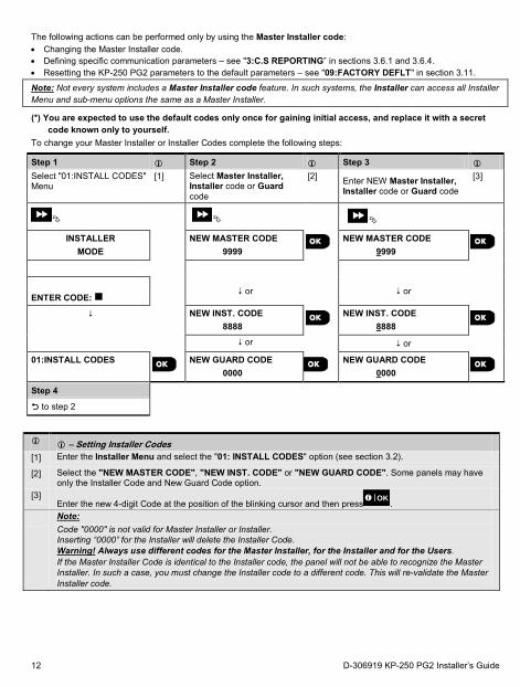
The following actions can be performed only by using the Master Installer code: • Changing the Master Installer code. • Defining specific communication parameters – see "3:C.S REPORTING” in sections 3.6.1 and 3.6.4. • Resetting the KP-250 PG2 parameters to the default parameters – see "09:FACTORY DEFLT" in section 3.11. Note: Not every system includes a Master Installer code feature. In such systems, the Installer can access all Installer Menu and sub-menu options the same as a Master Installer.
(*) You are expected to use the default codes only once for gaining initial access, and replace it with a secret code known only to yourself.
To change your Master Installer or Installer Codes complete the following steps:
Step 1 Step 2 Step 3
Select "01:INSTALL CODES" Menu
[1] Select Master Installer, Installer code or Guard code
[2] Enter NEW Master Installer, Installer code or Guard code
[3]
INSTALLER MODE
NEW MASTER CODE 9999
NEW MASTER CODE 9999
ENTER CODE:
or
or
NEW INST. CODE 8888
NEW INST. CODE 8888
or or
01:INSTALL CODES
NEW GUARD CODE 0000
NEW GUARD CODE 0000
Step 4 to step 2
– Setting Installer Codes
[1] Enter the Installer Menu and select the "01: INSTALL CODES" option (see section 3.2).
[2] Select the "NEW MASTER CODE", "NEW INST. CODE" or "NEW GUARD CODE". Some panels may have only the Installer Code and New Guard Code option.
[3] Enter the new 4-digit Code at the position of the blinking cursor and then press .
Note: Code "0000" is not valid for Master Installer or Installer. Inserting “0000” for the Installer will delete the Installer Code. Warning! Always use different codes for the Master Installer, for the Installer and for the Users. If the Master Installer Code is identical to the Installer code, the panel will not be able to recognize the Master Installer. In such a case, you must change the Installer code to a different code. This will re-validate the Master Installer code.
12 D-306919 KP-250 PG2 Installer’s Guide
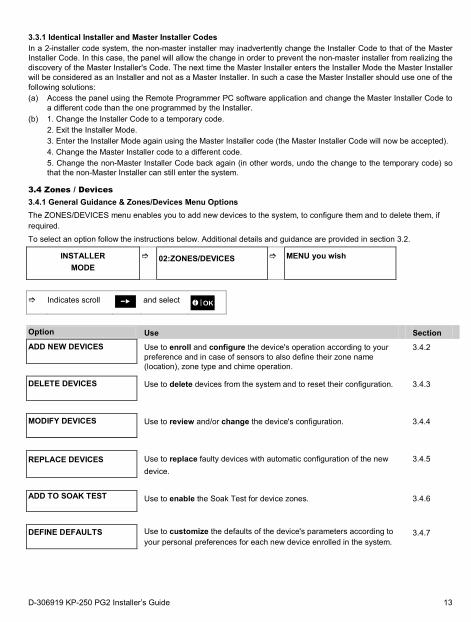
3.3.1 Identical Installer and Master Installer Codes In a 2-installer code system, the non-master installer may inadvertently change the Installer Code to that of the Master Installer Code. In this case, the panel will allow the change in order to prevent the non-master installer from realizing the discovery of the Master Installer's Code. The next time the Master Installer enters the Installer Mode the Master Installer will be considered as an Installer and not as a Master Installer. In such a case the Master Installer should use one of the following solutions: (a) Access the panel using the Remote Programmer PC software application and change the Master Installer Code to
a different code than the one programmed by the Installer. (b) 1. Change the Installer Code to a temporary code.
2. Exit the Installer Mode. 3. Enter the Installer Mode again using the Master Installer code (the Master Installer Code will now be accepted). 4. Change the Master Installer code to a different code. 5. Change the non-Master Installer Code back again (in other words, undo the change to the temporary code) so that the non-Master Installer can still enter the system.
3.4 Zones / Devices 3.4.1 General Guidance & Zones/Devices Menu Options The ZONES/DEVICES menu enables you to add new devices to the system, to configure them and to delete them, if required. To select an option follow the instructions below. Additional details and guidance are provided in section 3.2.
INSTALLER MODE
02:ZONES/DEVICES
MENU you wish
Indicates scroll and select
Option Use Section ADD NEW DEVICES
Use to enroll and configure the device's operation according to your preference and in case of sensors to also define their zone name (location), zone type and chime operation.
3.4.2
DELETE DEVICES
Use to delete devices from the system and to reset their configuration. 3.4.3
MODIFY DEVICES
Use to review and/or change the device's configuration. 3.4.4
REPLACE DEVICES
Use to replace faulty devices with automatic configuration of the new device.
3.4.5
ADD TO SOAK TEST
Use to enable the Soak Test for device zones. 3.4.6
DEFINE DEFAULTS
Use to customize the defaults of the device's parameters according to your personal preferences for each new device enrolled in the system.
3.4.7
D-306919 KP-250 PG2 Installer’s Guide 13
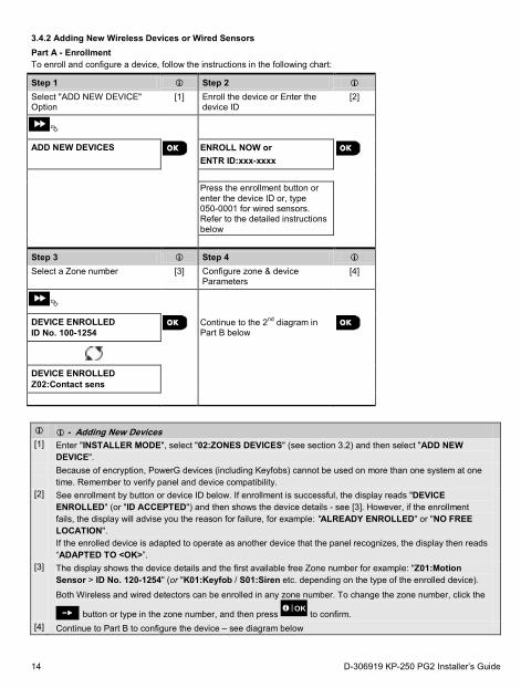
3.4.2 Adding New Wireless Devices or Wired Sensors Part A - Enrollment To enroll and configure a device, follow the instructions in the following chart:
Step 1 Step 2
Select "ADD NEW DEVICE" Option
[1] Enroll the device or Enter the device ID
[2]
ADD NEW DEVICES
ENROLL NOW or ENTR ID:xxx-xxxx
Press the enrollment button or enter the device ID or, type 050-0001 for wired sensors. Refer to the detailed instructions below
Step 3 Step 4
Select a Zone number [3] Configure zone & device Parameters
[4]
DEVICE ENROLLED ID No. 100-1254 Continue to the 2nd diagram in
Part B below
DEVICE ENROLLED Z02:Contact sens
- Adding New Devices
[1] Enter "INSTALLER MODE", select "02:ZONES DEVICES" (see section 3.2) and then select "ADD NEW DEVICE".
Because of encryption, PowerG devices (including Keyfobs) cannot be used on more than one system at one time. Remember to verify panel and device compatibility.
[2] See enrollment by button or device ID below. If enrollment is successful, the display reads "DEVICE ENROLLED" (or "ID ACCEPTED") and then shows the device details - see [3]. However, if the enrollment fails, the display will advise you the reason for failure, for example: "ALREADY ENROLLED" or "NO FREE LOCATION". If the enrolled device is adapted to operate as another device that the panel recognizes, the display then reads “ADAPTED TO <OK>”.
[3] The display shows the device details and the first available free Zone number for example: "Z01:Motion Sensor > ID No. 120-1254" (or "K01:Keyfob / S01:Siren etc. depending on the type of the enrolled device).
Both Wireless and wired detectors can be enrolled in any zone number. To change the zone number, click the
button or type in the zone number, and then press to confirm. [4] Continue to Part B to configure the device – see diagram below
14 D-306919 KP-250 PG2 Installer’s Guide
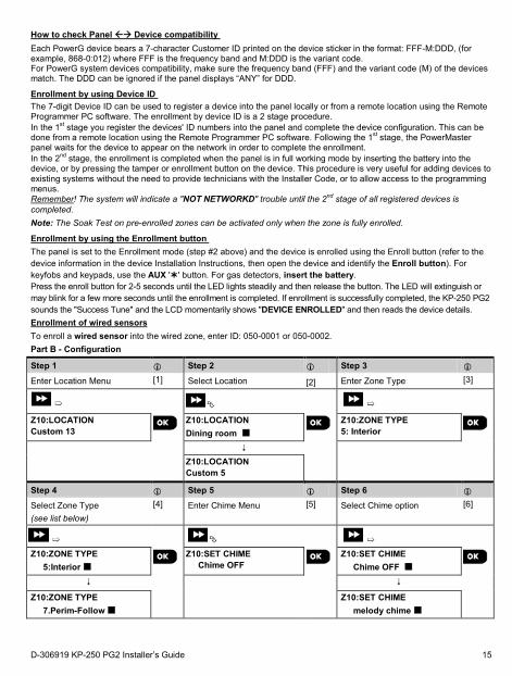
How to check Panel Device compatibility Each PowerG device bears a 7-character Customer ID printed on the device sticker in the format: FFF-M:DDD, (for example, 868-0:012) where FFF is the frequency band and M:DDD is the variant code. For PowerG system devices compatibility, make sure the frequency band (FFF) and the variant code (M) of the devices match. The DDD can be ignored if the panel displays “ANY” for DDD.
Enrollment by using Device ID The 7-digit Device ID can be used to register a device into the panel locally or from a remote location using the Remote Programmer PC software. The enrollment by device ID is a 2 stage procedure. In the 1st stage you register the devices' ID numbers into the panel and complete the device configuration. This can be done from a remote location using the Remote Programmer PC software. Following the 1st stage, the PowerMaster panel waits for the device to appear on the network in order to complete the enrollment. In the 2nd stage, the enrollment is completed when the panel is in full working mode by inserting the battery into the device, or by pressing the tamper or enrollment button on the device. This procedure is very useful for adding devices to existing systems without the need to provide technicians with the Installer Code, or to allow access to the programming menus. Remember! The system will indicate a "NOT NETWORKD" trouble until the 2nd stage of all registered devices is completed. Note: The Soak Test on pre-enrolled zones can be activated only when the zone is fully enrolled.
Enrollment by using the Enrollment button The panel is set to the Enrollment mode (step #2 above) and the device is enrolled using the Enroll button (refer to the device information in the device Installation Instructions, then open the device and identify the Enroll button). For keyfobs and keypads, use the AUX '' button. For gas detectors, insert the battery. Press the enroll button for 2-5 seconds until the LED lights steadily and then release the button. The LED will extinguish or may blink for a few more seconds until the enrollment is completed. If enrollment is successfully completed, the KP-250 PG2 sounds the "Success Tune" and the LCD momentarily shows "DEVICE ENROLLED" and then reads the device details. Enrollment of wired sensors To enroll a wired sensor into the wired zone, enter ID: 050-0001 or 050-0002. Part B - Configuration
Step 1 Step 2 Step 3
Enter Location Menu [1] Select Location [2] Enter Zone Type [3]
➯
➯
Z10:LOCATION Custom 13
Z10:LOCATION Dining room
Z10:ZONE TYPE 5: Interior
Z10:LOCATION
Custom 5
Step 4 Step 5 Step 6
Select Zone Type (see list below)
[4] Enter Chime Menu [5] Select Chime option [6]
➯
➯
Z10:ZONE TYPE 5:Interior
Z10:SET CHIME Chime OFF
Z10:SET CHIME Chime OFF
Z10:ZONE TYPE 7.Perim-Follow
Z10:SET CHIME melody chime
D-306919 KP-250 PG2 Installer’s Guide 15
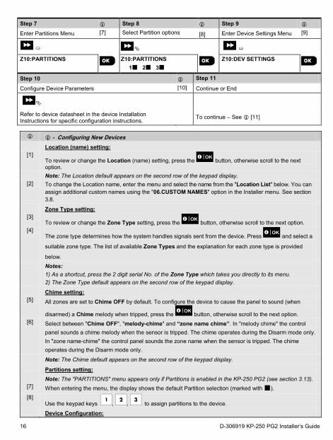
Step 7 Step 8 Step 9
Enter Partitions Menu [7] Select Partition options [8] Enter Device Settings Menu [9]
➯
➯
Z10:PARTITIONS
Z10:PARTITIONS 1 2 3
Z10:DEV SETTINGS
Step 10 Step 11
Configure Device Parameters [10] Continue or End
Refer to device datasheet in the device Installation Instructions for specific configuration instructions.
To continue – See [11]
- Configuring New Devices Location (name) setting:
[1] To review or change the Location (name) setting, press the button, otherwise scroll to the next option.
Note: The Location default appears on the second row of the keypad display. [2] To change the Location name, enter the menu and select the name from the "Location List" below. You can
assign additional custom names using the "06.CUSTOM NAMES" option in the Installer menu. See section 3.8.
Zone Type setting: [3]
To review or change the Zone Type setting, press the button, otherwise scroll to the next option. [4]
The zone type determines how the system handles signals sent from the device. Press and select a
suitable zone type. The list of available Zone Types and the explanation for each zone type is provided
below. Notes:
1) As a shortcut, press the 2 digit serial No. of the Zone Type which takes you directly to its menu. 2) The Zone Type default appears on the second row of the keypad display.
Chime setting: [5] All zones are set to Chime OFF by default. To configure the device to cause the panel to sound (when
disarmed) a Chime melody when tripped, press the button, otherwise scroll to the next option. [6] Select between "Chime OFF", "melody-chime" and “zone name chime”. In "melody chime" the control
panel sounds a chime melody when the sensor is tripped. The chime operates during the Disarm mode only. In "zone name-chime" the control panel sounds the zone name when the sensor is tripped. The chime operates during the Disarm mode only.
Note: The Chime default appears on the second row of the keypad display. Partitions setting:
Note: The "PARTITIONS" menu appears only if Partitions is enabled in the KP-250 PG2 (see section 3.13). [7] When entering the menu, the display shows the default Partition selection (marked with ). [8]
Use the keypad keys , , to assign partitions to the device. Device Configuration:
16 D-306919 KP-250 PG2 Installer’s Guide
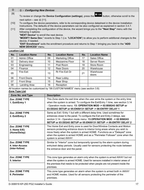
- Configuring New Devices
[9] To review or change the Device Configuration (settings), press the button, otherwise scroll to the next option – see [11].
[10] To configure the device parameters, refer to its corresponding device datasheet in the device Installation Instructions. The defaults of the device parameters can be also configured as explained in section 3.4.7.
[11] After completing the configuration of the device, the wizard brings you to the "Next Step" menu with the following 3 options: "NEXT Device" to enroll the next device. "MODIFY Same Dev." reverts to Step 1 (i.e. "LOCATION") to allow you to perform additional changes to the device, if needed. "EXIT Enrollment" exits the enrollment procedure and returns to Step 1 bringing you back to the "ADD NEW DEVICES" menu.
Location List No. Location Name No. Location Name No. Location Name 01 Admin Office 09 Marketing Office 17 Sales Office 02 Delivery door 10 Mezzanine Floor 18 Server Room 03 Engineering 11 Post Room 19 Store Room 04 Finance 12 Rear Doors 20 Warehouse
05 Fire Exit 13 Rr Fire Exit Dr 21 Warehouse doors
06 Front Doors 14 Rear Lobby 07 Front Shop 15 Rear Shop 08 Landing Area 16 Reception
All location names be customized by “06:CUSTOM NAMES” menu (see section 3.8) Zone Type List
Zone No. and Type Description Zxx: ZONE TYPE 1. Exit/Entry 1
This Zone starts the exit time when the user arms the system or the entry time when the system is armed. To configure the Exit/Entry 1 time, see section 3.14 - Operation mode menu: 13: OPERATION MOD -> 02:BS8243 SETUP or 03:DD243 SETUP or 05:EN50131 SETUP -> 08:ENTRY DELAY 1
Zxx: ZONE TYPE 2. Exit/Entry 2
Same as Exit / Entry 1 but with a different delay time. Used sometimes for entrances closer to the panel. To configure the Exit and Entry 2 delays, see section 3.14 - Operation mode menu: 13.OPERATION MOD -> 02:BS8243 SETUP or 03:DD243 SETUP or 05:EN50131 SETUP -> 09:ENTRY DELAY 2
Zxx: ZONE TYPE 3. Home E/E) (Home/Delay)
The Home Exit and Entry zone is used for Door/Window Contacts and Motion sensors protecting entrance doors to interior living areas where you wish to move freely when the system is armed HOME. Functions as a "Delayed" zone when the system is armed HOME and as a "Perimeter Follower" zone when the system is armed AWAY.
Zxx: ZONE TYPE 4. Inter-Access (Inter-follow)
Similar to "Interior" zone but temporarily ignored by the alarm system during entry/exit delay periods. Usually used for sensors protecting the route between the entrance door and the panel.
Zxx: ZONE TYPE 5. Interior
This zone type generates an alarm only when the system is armed AWAY but not when the system is armed HOME. Used for sensors installed in interior areas of the premises that needs to be protected when people are not present inside the premises.
Zxx: ZONE TYPE 6 .Perimeter
This zone type generates an alarm when the system is armed both in AWAY and HOME modes. Used for all sensors protecting the perimeter of the premises.
D-306919 KP-250 PG2 Installer’s Guide 17

Zone No. and Type Description
Zxx: ZONE TYPE 7. Perim-Access (Perim-follow)
Similar to "Perimeter" zone, but is temporarily ignored by the alarm system during entry/exit delay periods. Usually used for sensors protecting the route between the entrance door and the control panel.
Zxx: ZONE TYPE 8. 24h silent
This zone type is active 24 hours, even when system is DISARMED. It is used to report alarm events from sensors or manually activated buttons to the monitoring station or private telephones (as programmed) without activating the sirens.
Zxx: ZONE TYPE 9. 24h audible
Similar to 24hr silent zone, but also provides an audible siren alarm.
Zxx: ZONE TYPE 10. Emergency
This zone type is active 24 hours, even when the system is DISARMED. It is used to report an emergency event and to initiate an Emergency call to the monitoring stations or private telephones (as programmed).
Zxx: ZONE TYPE 11. Arming Key
An Arming key zone is used to control the arming and disarming of the system by an external wired system or simple key switch connected to the panel's wired zone input or a wired input of a PowerG device. Note: If the wired input of the panel or PowerG device is closed, the control panel will be armed. If it is opened, the control panel will be disarmed - refer to the PowerMaster-10/30 G2 Installer’s Guide, Figure 3.6b (PowerMaster-10 G2) / Figure 4.9b (PowerMaster-30 G2), or, PowerMaster-33 G2 Installer’s Guide, Figure 3.8b.
Zxx: ZONE TYPE 12. Non-Alarm
This zone does not create an alarm and is often used for non-alarm applications. For example, a detector used only for sounding a chime.
Zxx: ZONE TYPE 13. Fire
A Fire zone is used for connecting the MC-302E (magnetic contact with hard-wired input) to a wired smoke detector.
Zxx: ZONE TYPE 17. Guard keybox Note: Depending on the configuration this option may not be available.
A Guard keybox zone is usually connected to a metal safe containing the physical keys needed to enter the building. Following an alarm, the safe becomes available to a trusted Guard who can open the Guard keybox, obtain the keys and enter the secured premises. The Guard keybox zone acts just like a 24H audible zone. The Guard keybox zone also provides automatic audible internal sounder and external siren alarm that is immediately reported to the Monitoring Station (and does not depend on the Abort Time). Note: Opening/closing the Guard keybox causes the PowerMaster to signal the Monitoring Station.
Zxx: ZONE TYPE 18. Outdoor
A zone for outdoor areas where an activated alarm does not indicate intrusion into the house. This zone type generates an alarm when the system is armed both in AWAY and HOME modes. Events are sent to private phones and not to the Monitoring Station.
Zxx: ZONE TYPE 19. Int./Delay
This zone type behaves as an “Interior” zone when the system is armed ‘Home’ and as a “Delayed” zone when the system is armed ‘Away’.
Zxx: ZONE TYPE 20. Tamper
This is a 24 hour zone operating all of the time even when the system is disarmed. The tamper zone reports tamper alarm events from an external wired device. The behavior is the same as opening the tamper switch of a detector.
18 D-306919 KP-250 PG2 Installer’s Guide
Zone No. and Type Description
Zxx: ZONE TYPE 21. Line Fail
This is a 24 hour zone operating all of the time even when the system is disarmed. The line fail zone reports phone line failures from an external wired receiver that is connected to a phone line.
Zxx: ZONE TYPE 22. PSU Fail
This is a 24 hour zone operating all of the time even when the system is disarmed. The PSU fail zone reports power supply failures from an external wired device.
Zxx: ZONE TYPE 23. Panic
This is a 24 hour zone operating all of the time even when the system is disarmed. The panic zone reports panic events from any panic device to the monitoring station or private telephone numbers. A panic event generates an audible siren alarm.
Zxx: ZONE TYPE 24. Freezer Trbl
This zone type is active 24 hours, even when the system is disarmed. It is used to report freezer trouble.
(*) These Zone types are useful mainly to arm and disarm the system from inside the protected premises. If you arm and disarm the system from outside (without tripping any sensor), such as using a keyfob, it is preferred to use the other Zone Types.
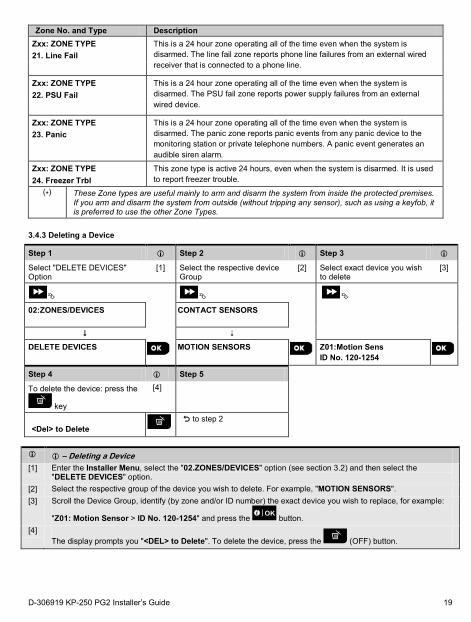
3.4.3 Deleting a Device
Step 1 Step 2 Step 3
Select "DELETE DEVICES" Option
[1] Select the respective device Group
[2] Select exact device you wish to delete
[3]
02:ZONES/DEVICES
CONTACT SENSORS
DELETE DEVICES
MOTION SENSORS
Z01:Motion Sens ID No. 120-1254
Step 4 Step 5
To delete the device: press the
key
[4]
<Del> to Delete
to step 2
– Deleting a Device [1] Enter the Installer Menu, select the "02.ZONES/DEVICES" option (see section 3.2) and then select the
"DELETE DEVICES" option. [2] Select the respective group of the device you wish to delete. For example, "MOTION SENSORS". [3] Scroll the Device Group, identify (by zone and/or ID number) the exact device you wish to replace, for example:
"Z01: Motion Sensor > ID No. 120-1254" and press the button. [4]
The display prompts you "<DEL> to Delete". To delete the device, press the (OFF) button.
D-306919 KP-250 PG2 Installer’s Guide 19
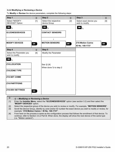
3.4.4 Modifying or Reviewing a Device To Modify or Review the device parameters, complete the following steps:
Step 1 Step 2 Step 3
Select "MODIFY DEVICES" Option
[1] Select the respective device Group
[2] Select exact device you wish to modify
[3]
02:ZONES/DEVICES
CONTACT SENSORS
MODIFY DEVICES
MOTION SENSORS
Z10:Motion Camra ID No. 140-1737
Step 4 Step 5 Select the Parameter you wish to modify
[4] Modify the Parameter
Z10:LOCATION
See [4] When done to step 2
Z10:ZONE TYPE
Z10:SET CHIME
Z10:PARTITIONS
Z10:DEV SETTINGS
– Modifying or Reviewing a Device [1] Enter the Installer Menu, select the "02:ZONES/DEVICES" option (see section 3.2) and then select the
"MODIFY DEVICES" option. [2] Select the respective group of the device you wish to review or modify. For example, "MOTION SENSORS". [3] Scroll the Device Group, identify by zone and/or ID number the exact device you wish to modify or review, for
example: "Z10:Motion Camra > ID No. 140-1737". [4] From here on the process is same as the configuration process that follows the enrollment of that device. To
continue, refer to Section 3.4.2 Part B. When done, the display will show the next device of the same type (i.e. "Motion camera").
20 D-306919 KP-250 PG2 Installer’s Guide
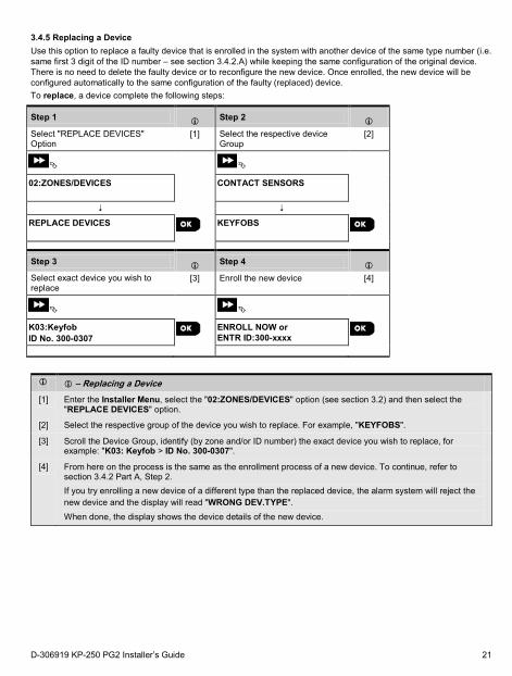
3.4.5 Replacing a Device Use this option to replace a faulty device that is enrolled in the system with another device of the same type number (i.e. same first 3 digit of the ID number – see section 3.4.2.A) while keeping the same configuration of the original device. There is no need to delete the faulty device or to reconfigure the new device. Once enrolled, the new device will be configured automatically to the same configuration of the faulty (replaced) device. To replace, a device complete the following steps:
Step 1 Step 2
Select "REPLACE DEVICES" Option
[1] Select the respective device Group
[2]
02:ZONES/DEVICES
CONTACT SENSORS
REPLACE DEVICES
KEYFOBS
Step 3 Step 4
Select exact device you wish to replace
[3] Enroll the new device [4]
K03:Keyfob ID No. 300-0307
ENROLL NOW or ENTR ID:300-xxxx
– Replacing a Device
[1] Enter the Installer Menu, select the "02:ZONES/DEVICES" option (see section 3.2) and then select the "REPLACE DEVICES" option.
[2] Select the respective group of the device you wish to replace. For example, "KEYFOBS".
[3] Scroll the Device Group, identify (by zone and/or ID number) the exact device you wish to replace, for example: "K03: Keyfob > ID No. 300-0307".
[4] From here on the process is the same as the enrollment process of a new device. To continue, refer to section 3.4.2 Part A, Step 2. If you try enrolling a new device of a different type than the replaced device, the alarm system will reject the new device and the display will read "WRONG DEV.TYPE". When done, the display shows the device details of the new device.
D-306919 KP-250 PG2 Installer’s Guide 21
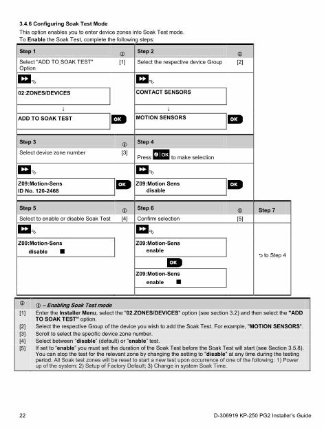
3.4.6 Configuring Soak Test Mode This option enables you to enter device zones into Soak Test mode. To Enable the Soak Test, complete the following steps:
Step 1 Step 2
Select "ADD TO SOAK TEST" Option
[1] Select the respective device Group [2]
02:ZONES/DEVICES
CONTACT SENSORS
ADD TO SOAK TEST
MOTION SENSORS
Step 3 Step 4 Select device zone number [3]
Press to make selection
Z09:Motion-Sens ID No. 120-2468
Z09:Motion Sens disable
Step 5 Step 6 Step 7 Select to enable or disable Soak Test [4] Confirm selection [5]
to Step 4
Z09:Motion-Sens disable
Z09:Motion-Sens enable
Z09:Motion-Sens enable
– Enabling Soak Test mode [1] Enter the Installer Menu, select the "02.ZONES/DEVICES" option (see section 3.2) and then select the "ADD
TO SOAK TEST" option. [2] Select the respective Group of the device you wish to add the Soak Test. For example, "MOTION SENSORS". [3] Scroll to select the specific device zone number. [4] Select between “disable” (default) or “enable” test. [5] If set to “enable” you must set the duration of the Soak Test before the Soak Test will start (see Section 3.5.8).
You can stop the test for the relevant zone by changing the setting to "disable" at any time during the testing period. All Soak test zones will be reset to start a new test upon occurrence of one of the following: 1) Power up of the system; 2) Setup of Factory Default; 3) Change in system Soak Time.
22 D-306919 KP-250 PG2 Installer’s Guide
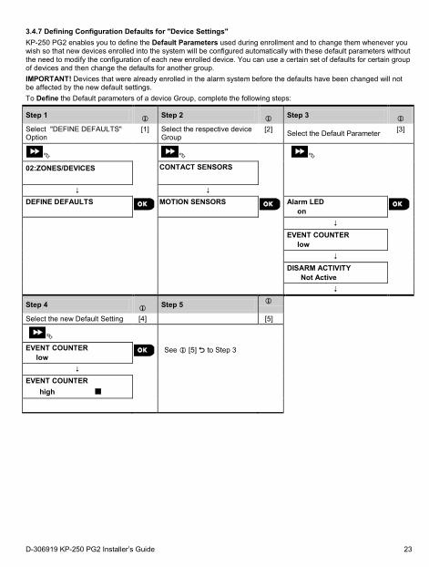
3.4.7 Defining Configuration Defaults for "Device Settings" KP-250 PG2 enables you to define the Default Parameters used during enrollment and to change them whenever you wish so that new devices enrolled into the system will be configured automatically with these default parameters without the need to modify the configuration of each new enrolled device. You can use a certain set of defaults for certain group of devices and then change the defaults for another group. IMPORTANT! Devices that were already enrolled in the alarm system before the defaults have been changed will not be affected by the new default settings. To Define the Default parameters of a device Group, complete the following steps:
Step 1 Step 2 Step 3
Select "DEFINE DEFAULTS" Option
[1] Select the respective device Group
[2] Select the Default Parameter [3]
02:ZONES/DEVICES
CONTACT SENSORS
DEFINE DEFAULTS
MOTION SENSORS
Alarm LED on
EVENT COUNTER
low DISARM ACTIVITY
Not Active
Step 4 Step 5
Select the new Default Setting [4] [5]
EVENT COUNTER low See [5] to Step 3
EVENT COUNTER
high
D-306919 KP-250 PG2 Installer’s Guide 23
– Changing Defaults
[1] Enter the Installer Menu, select the "02.ZONES/DEVICES" option (see section 3.2) and then select the "DEFINE DEFAULTS" option.
[2] Select the respective Group of the device you wish to define its defaults. For example, "MOTION SENSORS".
[3] Scroll the parameter list of the Device Group and select the Default Parameter you wish to change, for example: "EVENT COUNTER". The list combines the parameters of all devices in the group, for example, the parameters of all types of Motion sensors.
[4] In the example, the existing default setting of the "Event Counter" for enrolled motion sensors was "low" sensitivity (marked with ) . To change it to "high", scroll the menu until the display shows "high" and press
the button. The new default for the Event Counter parameter setting of Motion Sensors enrolled from now on will be "high".
[5] The new default does not affect motions sensors that were already enrolled before the change was made but only new motion sensors that will be enrolled in the alarm system after the change is performed.
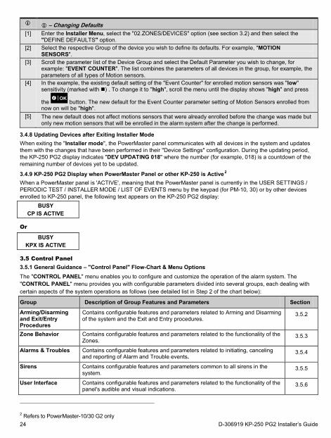
3.4.8 Updating Devices after Exiting Installer Mode When exiting the "Installer mode", the PowerMaster panel communicates with all devices in the system and updates them with the changes that have been performed in their "Device Settings" configuration. During the updating period, the KP-250 PG2 display indicates "DEV UPDATING 018" where the number (for example, 018) is a countdown of the remaining number of devices yet to be updated.
3.4.9 KP-250 PG2 Display when PowerMaster Panel or other KP-250 is Active2 When a PowerMaster panel is 'ACTIVE', meaning that the PowerMaster panel is currently in the USER SETTINGS / PERIODIC TEST / INSTALLER MODE / LIST OF EVENTS menu by the keypad (for PM-10, 30) or by other devices enrolled to KP-250 panel, the following text appears on the KP-250 PG2 display:
BUSY CP IS ACTIVE
Or
BUSY KPX IS ACTIVE
3.5 Control Panel 3.5.1 General Guidance – "Control Panel" Flow-Chart & Menu Options The "CONTROL PANEL" menu enables you to configure and customize the operation of the alarm system. The "CONTROL PANEL" menu provides you with configurable parameters divided into several groups, each dealing with certain aspects of the system operations as follows (see detailed list in Step 2 of the chart below):
Group Description of Group Features and Parameters Section
Arming/Disarming and Exit/Entry Procedures
Contains configurable features and parameters related to Arming and Disarming of the system and the Exit and Entry procedures.
3.5.2
Zone Behavior Contains configurable features and parameters related to the functionality of the Zones.
3.5.3
Alarms & Troubles Contains configurable features and parameters related to initiating, canceling and reporting of Alarm and Trouble events.
3.5.4
Sirens Contains configurable features and parameters common to all sirens in the system.
3.5.5
User Interface Contains configurable features and parameters related to the functionality of the panel's audible and visual indications.
3.5.6
2 Refers to PowerMaster-10/30 G2 only 24 D-306919 KP-250 PG2 Installer’s Guide
Jamming & Supervision
Contains configurable features and parameters related to detecting and reporting of RF Jamming and device Supervision (missing device) events.
3.5.7
Miscellaneous Contains a variety of other configurable features and parameters related to the system.
3.5.8
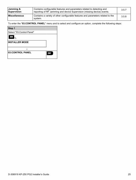
To enter the "03.CONTROL PANEL" menu and to select and configure an option, complete the following steps:
Step 1
Select "03.Control Panel"
INSTALLER MODE
03:CONTROL PANEL
D-306919 KP-250 PG2 Installer’s Guide 25
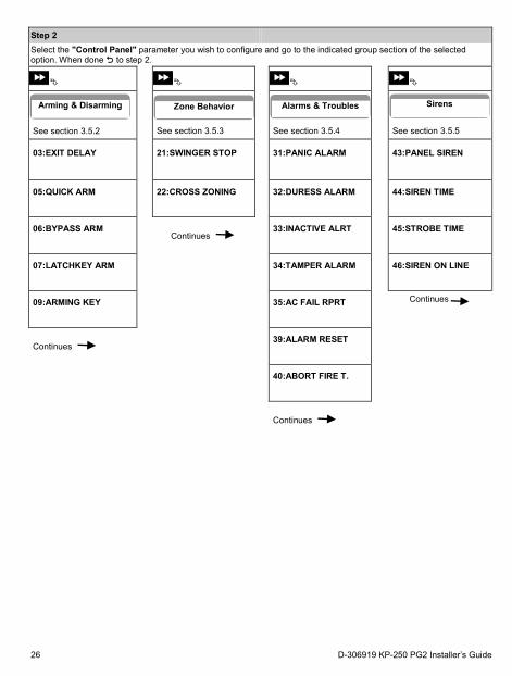
Step 2 Select the "Control Panel" parameter you wish to configure and go to the indicated group section of the selected option. When done to step 2.
See section 3.5.2 See section 3.5.3 See section 3.5.4 See section 3.5.5
03:EXIT DELAY
21:SWINGER STOP
31:PANIC ALARM
43:PANEL SIREN
05:QUICK ARM
22:CROSS ZONING
32:DURESS ALARM
44:SIREN TIME
06:BYPASS ARM
Continues 33:INACTIVE ALRT
45:STROBE TIME
07:LATCHKEY ARM
34:TAMPER ALARM
46:SIREN ON LINE
09:ARMING KEY
35:AC FAIL RPRT
Continues
Continues 39:ALARM RESET
40:ABORT FIRE T.
Continues
Arming & Disarming Zone Behavior Alarms & Troubles Sirens
26 D-306919 KP-250 PG2 Installer’s Guide
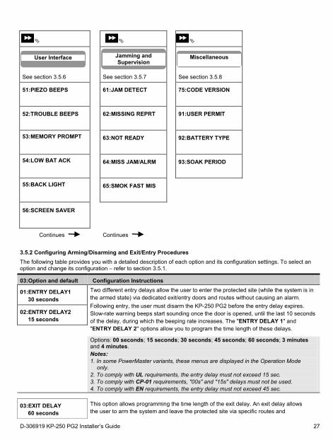
See section 3.5.6 See section 3.5.7 See section 3.5.8
51:PIEZO BEEPS
61:JAM DETECT
75:CODE VERSION
52:TROUBLE BEEPS
62:MISSING REPRT
91:USER PERMIT
53:MEMORY PROMPT
63:NOT READY
92:BATTERY TYPE
54:LOW BAT ACK
64:MISS JAM/ALRM
93:SOAK PERIOD
55:BACK LIGHT
65:SMOK FAST MIS
56:SCREEN SAVER
Continues Continues
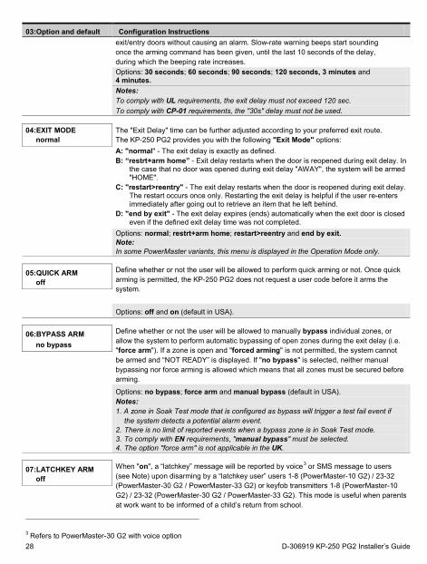
3.5.2 Configuring Arming/Disarming and Exit/Entry Procedures The following table provides you with a detailed description of each option and its configuration settings. To select an option and change its configuration – refer to section 3.5.1.
03:Option and default Configuration Instructions
01:ENTRY DELAY1 30 seconds
Two different entry delays allow the user to enter the protected site (while the system is in the armed state) via dedicated exit/entry doors and routes without causing an alarm. Following entry, the user must disarm the KP-250 PG2 before the entry delay expires. Slow-rate warning beeps start sounding once the door is opened, until the last 10 seconds of the delay, during which the beeping rate increases. The "ENTRY DELAY 1" and "ENTRY DELAY 2" options allow you to program the time length of these delays.
02:ENTRY DELAY2 15 seconds
Options: 00 seconds; 15 seconds; 30 seconds; 45 seconds; 60 seconds; 3 minutes and 4 minutes.
Notes: 1. In some PowerMaster variants, these menus are displayed in the Operation Mode
only. 2. To comply with UL requirements, the entry delay must not exceed 15 sec. 3. To comply with CP-01 requirements, "00s" and "15s" delays must not be used. 4. To comply with EN requirements, the entry delay must not exceed 45 sec.
03:EXIT DELAY 60 seconds
This option allows programming the time length of the exit delay. An exit delay allows the user to arm the system and leave the protected site via specific routes and
User Interface
Jamming and Supervision
Miscellaneous
D-306919 KP-250 PG2 Installer’s Guide 27
03:Option and default Configuration Instructions
exit/entry doors without causing an alarm. Slow-rate warning beeps start sounding once the arming command has been given, until the last 10 seconds of the delay, during which the beeping rate increases.
Options: 30 seconds; 60 seconds; 90 seconds; 120 seconds, 3 minutes and 4 minutes.
Notes: To comply with UL requirements, the exit delay must not exceed 120 sec. To comply with CP-01 requirements, the "30s" delay must not be used.
04:EXIT MODE
normal The "Exit Delay" time can be further adjusted according to your preferred exit route. The KP-250 PG2 provides you with the following "Exit Mode" options: A: "normal" - The exit delay is exactly as defined. B: “restrt+arm home” - Exit delay restarts when the door is reopened during exit delay. In
the case that no door was opened during exit delay "AWAY", the system will be armed "HOME".
C: "restart>reentry" - The exit delay restarts when the door is reopened during exit delay. The restart occurs once only. Restarting the exit delay is helpful if the user re-enters immediately after going out to retrieve an item that he left behind.
D: "end by exit" - The exit delay expires (ends) automatically when the exit door is closed even if the defined exit delay time was not completed.
Options: normal; restrt+arm home; restart>reentry and end by exit. Note: In some PowerMaster variants, this menu is displayed in the Operation Mode only.
05:QUICK ARM off
Define whether or not the user will be allowed to perform quick arming or not. Once quick arming is permitted, the KP-250 PG2 does not request a user code before it arms the system.
Options: off and on (default in USA).
06:BYPASS ARM no bypass
Define whether or not the user will be allowed to manually bypass individual zones, or allow the system to perform automatic bypassing of open zones during the exit delay (i.e. "force arm"). If a zone is open and "forced arming" is not permitted, the system cannot be armed and “NOT READY” is displayed. If "no bypass" is selected, neither manual bypassing nor force arming is allowed which means that all zones must be secured before arming.
Options: no bypass; force arm and manual bypass (default in USA).
Notes: 1. A zone in Soak Test mode that is configured as bypass will trigger a test fail event if
the system detects a potential alarm event. 2. There is no limit of reported events when a bypass zone is in Soak Test mode. 3. To comply with EN requirements, "manual bypass" must be selected. 4. The option "force arm" is not applicable in the UK.
07:LATCHKEY ARM off
When "on", a “latchkey” message will be reported by voice3 or SMS message to users (see Note) upon disarming by a “latchkey user” users 1-8 (PowerMaster-10 G2) / 23-32 (PowerMaster-30 G2 / PowerMaster-33 G2) or keyfob transmitters 1-8 (PowerMaster-10 G2) / 23-32 (PowerMaster-30 G2 / PowerMaster-33 G2). This mode is useful when parents at work want to be informed of a child’s return from school.
3 Refers to PowerMaster-30 G2 with voice option 28 D-306919 KP-250 PG2 Installer’s Guide
03:Option and default Configuration Instructions Options: off and on.
Note: To enable the reporting, you must configure the system to report "alrt" events to Private users (Latchkey belongs to the "alerts" group of events). Refer to section 3.6.5 "REPORTED EVENTS" option in both "VOICE REPORT" & "SMS REPORT" menus.
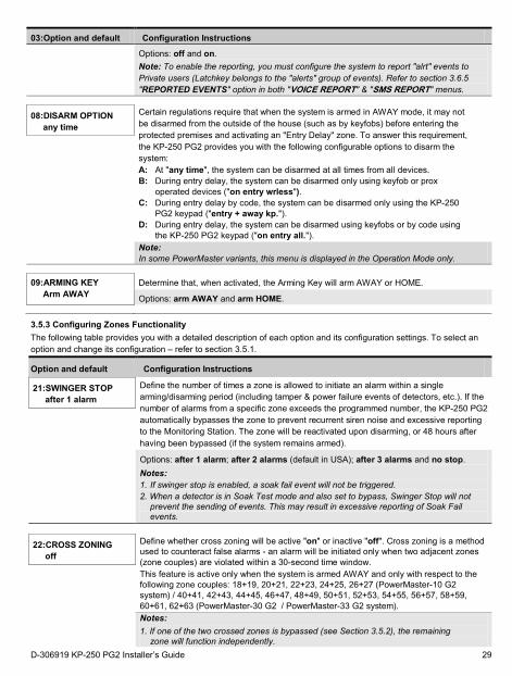
08:DISARM OPTION any time
Certain regulations require that when the system is armed in AWAY mode, it may not be disarmed from the outside of the house (such as by keyfobs) before entering the protected premises and activating an "Entry Delay" zone. To answer this requirement, the KP-250 PG2 provides you with the following configurable options to disarm the system: A: At "any time", the system can be disarmed at all times from all devices. B: During entry delay, the system can be disarmed only using keyfob or prox
operated devices ("on entry wrless"). C: During entry delay by code, the system can be disarmed only using the KP-250
PG2 keypad ("entry + away kp."). D: During entry delay, the system can be disarmed using keyfobs or by code using
the KP-250 PG2 keypad ("on entry all.").
Note: In some PowerMaster variants, this menu is displayed in the Operation Mode only.
09:ARMING KEY Arm AWAY
Determine that, when activated, the Arming Key will arm AWAY or HOME.
Options: arm AWAY and arm HOME.
3.5.3 Configuring Zones Functionality The following table provides you with a detailed description of each option and its configuration settings. To select an option and change its configuration – refer to section 3.5.1.
Option and default Configuration Instructions
21:SWINGER STOP after 1 alarm
Define the number of times a zone is allowed to initiate an alarm within a single arming/disarming period (including tamper & power failure events of detectors, etc.). If the number of alarms from a specific zone exceeds the programmed number, the KP-250 PG2 automatically bypasses the zone to prevent recurrent siren noise and excessive reporting to the Monitoring Station. The zone will be reactivated upon disarming, or 48 hours after having been bypassed (if the system remains armed).
Options: after 1 alarm; after 2 alarms (default in USA); after 3 alarms and no stop. Notes: 1. If swinger stop is enabled, a soak fail event will not be triggered. 2. When a detector is in Soak Test mode and also set to bypass, Swinger Stop will not
prevent the sending of events. This may result in excessive reporting of Soak Fail events.
22:CROSS ZONING off
Define whether cross zoning will be active "on" or inactive "off". Cross zoning is a method used to counteract false alarms - an alarm will be initiated only when two adjacent zones (zone couples) are violated within a 30-second time window. This feature is active only when the system is armed AWAY and only with respect to the following zone couples: 18+19, 20+21, 22+23, 24+25, 26+27 (PowerMaster-10 G2 system) / 40+41, 42+43, 44+45, 46+47, 48+49, 50+51, 52+53, 54+55, 56+57, 58+59, 60+61, 62+63 (PowerMaster-30 G2 / PowerMaster-33 G2 system).
Notes: 1. If one of the two crossed zones is bypassed (see Section 3.5.2), the remaining
zone will function independently. D-306919 KP-250 PG2 Installer’s Guide 29
Option and default Configuration Instructions 2. It is recommended that crossed zones will be only zones used for detection of
burglary i.e. "Zone Types": Entry/ Exit, Interior, Perimeter and Perimeter follower. 3. If a cross zone is in Soak Test mode, then each zone of this zone couple functions
independently. Important! Do not define "cross zoning" to any other zone types such as Fire, Emergency, 24h audible, 24h silent etc.
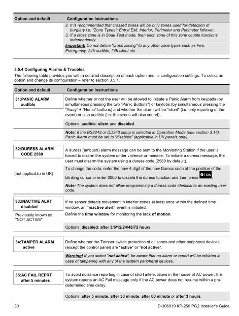
3.5.4 Configuring Alarms & Troubles The following table provides you with a detailed description of each option and its configuration settings. To select an option and change its configuration – refer to section 3.5.1.
Option and default Configuration Instructions
31:PANIC ALARM audible
Define whether or not the user will be allowed to initiate a Panic Alarm from keypads (by simultaneous pressing the two "Panic Buttons") or keyfobs (by simultaneous pressing the "Away" + "Home" buttons) and whether the alarm will be "silent" (i.e. only reporting of the event) or also audible (i.e. the sirens will also sound).
Options: audible; silent and disabled.
Note: If the BS8243 or DD243 setup is selected in Operation Mode (see section 3.14), Panic Alarm must be set to “disabled” (applicable in UK panels only).
32:DURESS ALARM CODE 2580
A duress (ambush) alarm message can be sent to the Monitoring Station if the user is forced to disarm the system under violence or menace. To initiate a duress message, the user must disarm the system using a duress code (2580 by default).
(not applicable in UK) To change the code, enter the new 4-digit of the new Duress code at the position of the
blinking cursor or enter 0000 to disable the duress function and then press .
Note: The system does not allow programming a duress code identical to an existing user code.
33:INACTIVE ALRT disabled
If no sensor detects movement in interior zones at least once within the defined time window, an “inactive alert" event is initiated. Define the time window for monitoring the lack of motion. Previously known as
"NOT ACTIVE"
Options: disabled; after 3/6/12/24/48/72 hours
34:TAMPER ALARM active
Define whether the Tamper switch protection of all zones and other peripheral devices (except the control panel) are "active" or "not active".
Warning! If you select "not active", be aware that no alarm or report will be initiated in case of tampering with any of the system peripheral devices.
35:AC FAIL REPRT after 5 minutes
To avoid nuisance reporting in case of short interruptions in the house of AC power, the system reports an AC Fail message only if the AC power does not resume within a pre-determined time delay.
Options: after 5 minute, after 30 minute, after 60 minute or after 3 hours.
30 D-306919 KP-250 PG2 Installer’s Guide
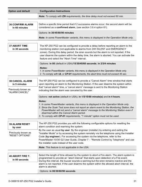
Option and default Configuration Instructions
Note: To comply with EN requirements, the time delay must not exceed 60 min.
36:CONFIRM ALARM in 60 minutes
Define a specific time period that if 2 successive alarms occur, the second alarm will be considered as a confirmed alarm, (see section 3.6.4 option 61).
Options: in 30/45/60/90 minutes
Note: In some PowerMaster variants, this menu is displayed in the Operation Mode only.
37:ABORT TIME in 30 seconds
The KP-250 PG2 can be configured to provide a delay before reporting an alarm to the monitoring station (not applicable to alarms from 24H SILENT and EMERGENCY zones). During this delay period, the siren sounds but the alarm is not reported. If the user disarms the system within the delay time, the alarm is aborted. You can activate the feature and select the "Abort Time" interval.
Options: in 00 (default in USA)/15/30/45/60 seconds; in 2/3/4 minutes
Notes: 1. In some PowerMaster variants, this menu is displayed in the Operation Mode only. 2. To comply with UL or CP-01 requirements, the abort time must not exceed 45 sec.
38:CANCEL ALARM in 5 minutes
The KP-250 PG2 can be configured to provide a ”Cancel Alarm” time window that starts upon reporting an alarm to the Monitoring Station. If the user disarms the system within that "cancel alarm" time, a “cancel alarm” message is sent to the Monitoring Station indicating that the alarm was canceled by the user. Previously known as
"ALARM CANCEL"
Options: not active (default in USA); in 1/5/15/60 minute(s) and in 4 hours.
Notes: 1. In some PowerMaster variants, this menu is displayed in the Operation Mode only. 2. Since the Soak Test zone does not report an alarm event to the Monitoring Station, the
PowerMaster will not send a “cancel alarm” message to the Monitoring Station even if disarmed within the Cancel Alarm period.
3. To comply with CP-01 requirements, "1 minute" option must not be used.
39:ALARM RESET
by user The KP-250 PG2 provides you with the following configurable options for resetting the alarm condition and rearming the system: By the user as usual by user. By the engineer (installer) by entering and exiting the "Installer Mode" or by accessing the system remotely via the telephone using the Installer Code (by engineer). For accessing the system via the telephone, refer to the PowerMaster-10/30 G2 User Guide, Chapter 7 – "Remote Control by Telephone" and use the installer code instead of the user code.
Previously known as "RESET OPTIONS"
Note: This feature is not applicable in the USA.
40:ABORT FIRE T. in 00 seconds
Select the length of time allowed by the system to abort a Fire alarm. The alarm system is programmed to provide an “abort interval” that starts upon detection of a Fire event. During this interval, the buzzer sounds a warning but the siren remains inactive and the alarm is not reported. If the user disarms the system within the allowed abort interval, the alarm is aborted.
Options: in 00/30/60/90 seconds
D-306919 KP-250 PG2 Installer’s Guide 31
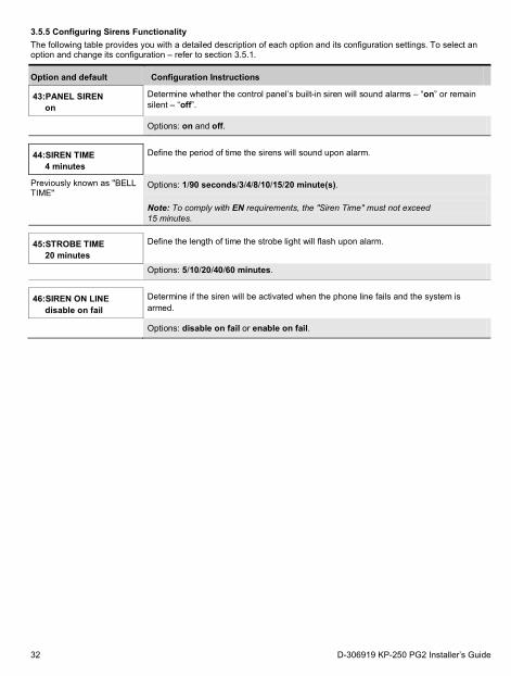
3.5.5 Configuring Sirens Functionality The following table provides you with a detailed description of each option and its configuration settings. To select an option and change its configuration – refer to section 3.5.1.
Option and default Configuration Instructions
43:PANEL SIREN on
Determine whether the control panel’s built-in siren will sound alarms – “on” or remain silent – “off”.
Options: on and off.
44:SIREN TIME
4 minutes Define the period of time the sirens will sound upon alarm.
Previously known as "BELL TIME"
Options: 1/90 seconds/3/4/8/10/15/20 minute(s).
Note: To comply with EN requirements, the "Siren Time" must not exceed 15 minutes.
45:STROBE TIME 20 minutes
Define the length of time the strobe light will flash upon alarm.
Options: 5/10/20/40/60 minutes.
46:SIREN ON LINE disable on fail
Determine if the siren will be activated when the phone line fails and the system is armed.
Options: disable on fail or enable on fail.
32 D-306919 KP-250 PG2 Installer’s Guide
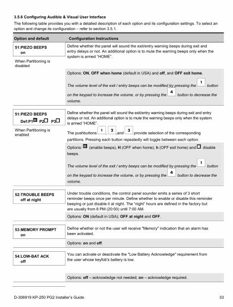
3.5.6 Configuring Audible & Visual User Interface The following table provides you with a detailed description of each option and its configuration settings. To select an option and change its configuration – refer to section 3.5.1.
Option and default Configuration Instructions
51:PIEZO BEEPS on
Define whether the panel will sound the exit/entry warning beeps during exit and entry delays or not. An additional option is to mute the warning beeps only when the system is armed “HOME”.
When Partitioning is disabled
Options: ON, OFF when home (default in USA) and off, and OFF exit home.
The volume level of the exit / entry beeps can be modified by pressing the button
on the keypad to increase the volume, or by pressing the button to decrease the volume.
51:PIEZO BEEPS
Def:P1 P2 P3
Define whether the panel will sound the exit/entry warning beeps during exit and entry delays or not. An additional option is to mute the warning beeps only when the system is armed “HOME”.
The pushbuttons , ,and provide selection of the corresponding
partitions. Pressing each button repeatedly will toggle between each option.
When Partitioning is enabled
Options: (enable beeps), H (OFF when home), h (OFF exit home) and disable beeps.
The volume level of the exit / entry beeps can be modified by pressing the button
on the keypad to increase the volume, or by pressing the button to decrease the volume.
52:TROUBLE BEEPS off at night
Under trouble conditions, the control panel sounder emits a series of 3 short reminder beeps once per minute. Define whether to enable or disable this reminder beeping or just disable it at night. The “night” hours are defined in the factory but are usually from 8 PM (20:00) until 7:00 AM.
Options: ON (default in USA); OFF at night and OFF.
53:MEMORY PROMPT on
Define whether or not the user will receive "Memory" indication that an alarm has been activated.
Options: on and off.
54:LOW-BAT ACK off
You can activate or deactivate the "Low Battery Acknowledge" requirement from the user whose keyfob's battery is low.
Options: off – acknowledge not needed; on – acknowledge required.
D-306919 KP-250 PG2 Installer’s Guide 33
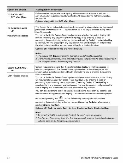
Option and default Configuration Instructions
55:BACK LIGHT OFF after 10sec
Define whether the panel's back lighting will remain on at all times or will turn on only when a key is pressed and turn off within 10 seconds if no further keystrokes are sensed.
Options: always ON and OFF after 10sec.
56:SCREEN SAVER off
The Screen Saver option (when activated) replaces the status display on the control panel with “PowerMaster-10” / “PowerMaster-30” if no key is pressed during more than 30 seconds. You can activate the Screen Saver and determine whether the status display will resume following any key press (refresh by Key) or by entering a code or presenting the proximity tag to the tag reader (refresh by Code). If refresh by Key is selected, the first pressing of any key (except Fire and Emergency) will produce the status display and the second press will perform the key function.
With Partition disabled
Options: off; refresh by code and refresh by key.
Notes: 1. To comply with EN requirements, "refresh by code" must be selected. 2. For Fire and Emergency keys, the first key press will produce the status display and
will also perform the Fire/Emergency function.
56:SCREEN SAVER
off
Certain regulations require that the system status display will not be exposed to unauthorized persons. The Screen Saver option (when activated) replaces the system status indication on the LCD with idle text if no key is pressed during more than 30 seconds. You can activate the Screen Saver option and determine whether the status display will resume following any key press (Text - by Key) or by entering a code or presenting a proximity tag to the tag reader (Text - by Code). If Text by Key is selected, the first pressing of any key (except Fire and Emergency) will produce the status display and the second press will perform the key function. You can also determine that if no key is pressed during more than 30 seconds the date and time will appear on the display. You can determine that normal display will
return after pressing the button followed by entering the user code or
presenting the proximity tag to the tag reader (Clock - by Code) or after pressing any key (Clock - by Key).
With Partition enabled
Options: off; Text - by code; Text - by Key; Clock - by Code; Clock - by Key.
Note: 1. To comply with EN requirements, "refresh by code" must be selected. 2. For Fire and Emergency keys, the first key press will produce the status display and
will also perform the Fire/Emergency function.
34 D-306919 KP-250 PG2 Installer’s Guide
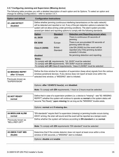
3.5.7 Configuring Jamming and Supervision (Missing device) The following table provides you with a detailed description of each option and its Options. To select an option and change its setting (configuration) – refer to section 3.5.1.
Option and default Configuration Instructions
61:JAM DETECT disabled
Define whether jamming (continuous interfering transmissions on the radio network) will be detected and reported or not. If any of the jam detection options is selected, the system will not allow arming under jamming conditions. The alarm system provides several jam detect and reporting options to comply with the following standards:
Option Standard Detection and Reporting occurs when: UL 20/20 USA There is continuous 20 seconds of
jamming EN 30/60 Europe There is an accumulated 30 seconds of
jamming within 60 sec. Class 6 (30/60) British
Standard Like EN (30/60) but the event will be reported only if the jamming duration exceeds 5 minutes.
disabled No jamming detection and reporting.
Notes: To comply with UL requirements, "UL 20/20" must be selected. To comply with EN requirements, "EN 30/60" must be selected. To comply with UK Class-6 requirements, "class 6 (30/60)" must be selected.
62:MISSING REPRT after 12 hours
Define the time window for reception of supervision (keep alive) signals from the various wireless peripheral devices. If any device does not report at least once within the selected time window, a “MISSING” alert is initiated.
Previously known as "SUPERVISION"
Options: after 1/2/4/8/12 hour(s); and disabled.
Note: To comply with EN requirements, 1 hour or 2 hours must be selected.
63:NOT READY normal
Define that in case of a supervision problem (i.e. a device is "missing" - see "62: MISSING REPRT") whether the system will continue to operate as normal or the system status will become "Not Ready" (upon missing) for as long as the "MISSING" trouble exists.
Options: normal and if missing dev. 64:MISS/JAM ALRM
normal "EN standards" require that if a supervision (missing) or jamming trouble occurs during AWAY arming, the siren will sound and the event will be reported as a tamper event. Define whether the system will behave according to EN standard or as normal. Previously known as
"BELL/REP.OPT"
Note: To comply with EN requirements "EN standard" must be selected. 65:SMOK FAST MIS
disable Determine that If the smoke detector does not report at least once within a time window of 200 seconds, a “MISSING” alert is initiated.
Options: disable and enable
D-306919 KP-250 PG2 Installer’s Guide 35
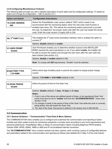
3.5.8 Configuring Miscellaneous Features The following table provides you with a detailed description of each option and its configuration settings. To select an option and change its configuration – refer to section 3.5.1.
Option and default Configuration Instructions
75:CODE VERSION 000
Define the PowerMaster code version (default "000") which needs to be synchronized with the monitoring station when the anti-code reset function is enabled (see menu 39). This allows the monitoring station personnel to provide the user, by telephone, the proper reset code after the user has stated the Quote code. Enter the code version (3 digits) 000 to 255.
80: 3rd PARTY H.A This enables the 3rd party home automation interface, that is, enables the option to connect 3rd
Options: disable (default) or enable.
91:USER PERMIT disable
User Permission enables you to determine whether access to the INSTALLER MODE requires the user's permission or not. If you select enable, the installer will be able to access the system only through the user menu after the user code has been entered (see section 3.2).
Options: disable or enable (default in UK).
Note: To comply with EN requirements, "Enable" must be selected. 92:BATTERY TYPE
7.2V NiMH Define which type of battery pack is used for the system to supply proper charge current.
Options: 7.2V NiMH or 9.6V NiMH (default in UK).
93:SOAK PERIOD disable
Define the period of time for the Soak Test.
Options: disable (default), 7 days, 14 days or 21 days. Notes: 1. If set to one of the above pre-defined period of times, to be operational Soak Test
mode must also be set to “enable” test from the “02:ZONES/DEVICES” menu (see Section 3.4.6).
2. If a change is made to the period of time of the Soak Test while the zone is currently being tested, this will restart the Soak Test.
3. The start of the Soak Test period is defined in the factory from 9 AM (09:00).
3.6 Communication 3.6.1 General Guidance – "Communication" Flow-Chart & Menu Options The COMMUNICATION menu enables you to configure and customize the communication and reporting of alarm, troubles and other system events for monitoring companies or private users according to your local requirements and personal preferences. PowerMaster offers a variety of communication means including telephone PSTN landline, Cellular GSM, GPRS, EMAIL, MMS or SMS and IP via broadband internet connection.
The "04.COMMUNICATION" menu contains several sub-menu options, each covering a group of configurable features and parameters related to the communication and reporting as follows (see detailed list in Step 3 of the chart below):
36 D-306919 KP-250 PG2 Installer’s Guide
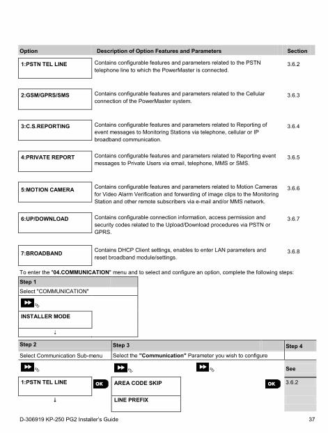
Option Description of Option Features and Parameters Section
1:PSTN TEL LINE
Contains configurable features and parameters related to the PSTN telephone line to which the PowerMaster is connected.
3.6.2
2:GSM/GPRS/SMS
Contains configurable features and parameters related to the Cellular connection of the PowerMaster system.
3.6.3
3:C.S.REPORTING
Contains configurable features and parameters related to Reporting of event messages to Monitoring Stations via telephone, cellular or IP broadband communication.
3.6.4
4:PRIVATE REPORT
Contains configurable features and parameters related to Reporting event messages to Private Users via email, telephone, MMS or SMS.
3.6.5
5:MOTION CAMERA
Contains configurable features and parameters related to Motion Cameras for Video Alarm Verification and forwarding of image clips to the Monitoring Station and other remote subscribers via e-mail and/or MMS network.
3.6.6
6:UP/DOWNLOAD
Contains configurable connection information, access permission and security codes related to the Upload/Download procedures via PSTN or GPRS.
3.6.7
7:BROADBAND
Contains DHCP Client settings, enables to enter LAN parameters and reset broadband module/settings.
3.6.8
To enter the "04.COMMUNICATION" menu and to select and configure an option, complete the following steps:
Step 1
Select "COMMUNICATION"
INSTALLER MODE
Step 2 Step 3 Step 4 Select Communication Sub-menu Select the "Communication" Parameter you wish to configure
See
1:PSTN TEL LINE
AREA CODE SKIP
3.6.2
LINE PREFIX
D-306919 KP-250 PG2 Installer’s Guide 37
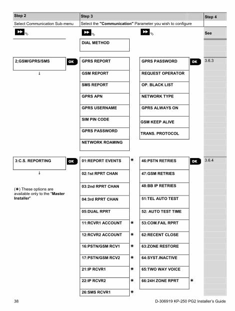
Step 2 Step 3 Step 4 Select Communication Sub-menu Select the "Communication" Parameter you wish to configure
See
DIAL METHOD
2;GSM/GPRS/SMS
GPRS REPORT
GPRS PASSWORD
3.6.3
GSM REPORT
REQUEST OPERATOR
SMS REPORT
OP. BLACK LIST
GPRS APN
NETWORK TYPE
GPRS USERNAME
GPRS ALWAYS ON
SIM PIN CODE
GSM KEEP ALIVE
GPRS PASSWORD
TRANS. PROTOCOL
NETWORK ROAMING
3:C.S. REPORTING
01:REPORT EVENTS
46:PSTN RETRIES
3.6.4
02:1st RPRT CHAN 47:GSM RETRIES
() These options are available only to the "Master Installer"
03:2nd RPRT CHAN
48:BB IP RETRIES
04:3rd RPRT CHAN
51:TEL AUTO TEST
05:DUAL RPRT
52: AUTO TEST TIME
11:RCVR1 ACCOUNT
53:COM.FAIL RPRT
12:RCVR2 ACCOUNT
62:RECENT CLOSE
16:PSTN/GSM RCV1
63:ZONE RESTORE
17:PSTN/GSM RCV2
64:SYST.INACTIVE
21:IP RCVR1
65:TWO WAY VOICE
22:IP RCVR2
66:24H ZONE RPRT
26:SMS RCVR1
38 D-306919 KP-250 PG2 Installer’s Guide
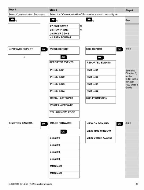
Step 2 Step 3 Step 4 Select Communication Sub-menu Select the "Communication" Parameter you wish to configure
See
27:SMS RCVR2 28:RCVR 1 DNS
29: RCVR 2 DNS 41:PSTN FORMAT
4:PRIVATE REPORT
VOICE REPORT SMS REPORT
3.6.5
REPORTED EVENTS
REPORTED EVENTS
Private tel#1
SMS tel#1
See also Chapter 6, section B.12, in the KP-250 PG2 User’s Guide
Private tel#2
SMS tel#2
Private tel#3
SMS tel#3
Private tel#4
SMS tel#4
REDIAL ATTEMPTS
SMS PERMISSION
VOICE->PRIVATE
TEL.ACKNOWLEDGE
5:MOTION CAMERA
IMAGE FORWARD
VIEW ON DEMAND
3.6.6
VIEW TIME WINDOW
e-mail#1
VIEW OTHER ALARM
e-mail#2
e-mail#3
e-mail#4
MMS tel#1
MMS tel#2
D-306919 KP-250 PG2 Installer’s Guide 39
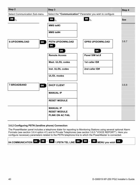
Step 2 Step 3 Step 4 Select Communication Sub-menu Select the "Communication" Parameter you wish to configure
See
MMS tel#3
MMS tel#4
6:UP/DOWNLOAD
PSTN UP/DOWNLOAD
GPRS UP/DOWNLOAD
3.6.7
Remote Access
Panel SIM tel.#
Mast. UL/DL codes
1st caller ID#
Inst. UL/DL codes
2nd caller ID#
UL/DL modes
7:BROADBAND
DHCP CLIENT
3.6.8
MANUAL IP
RESET MODULE
MANUAL IP RESET MODULE PLINK ON AC FAIL
3.6.2 Configuring PSTN (landline phone) Connection The PowerMaster panel includes a telephone dialer for reporting to Monitoring Stations using several optional Alarm Formats (see section 3.6.4 option 41) and to Private Telephones (see section 3.6.5 "VOICE REPORT"). Here you configure necessary parameters related to the PSTN telephone line to which the PowerMaster is connected.
04:COMMUNICATION ⋅⋅⋅ 1:PSTN TEL LINE ⋅⋅⋅ MENU you wish
40 D-306919 KP-250 PG2 Installer’s Guide
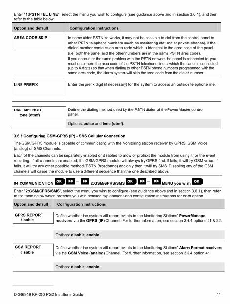
Enter "1:PSTN TEL LINE", select the menu you wish to configure (see guidance above and in section 3.6.1), and then refer to the table below.
Option and default Configuration Instructions
AREA CODE SKIP
In some older PSTN networks, it may not be possible to dial from the control panel to other PSTN telephone numbers (such as monitoring stations or private phones), if the dialed number contains an area code which is identical to the area code of the panel (i.e. both the panel and the other numbers are in the same PSTN area code). If you encounter the same problem with the PSTN network the panel is connected to, you must enter here the area code of the PSTN telephone line to which the panel is connected (up to 4 digits) so that when dialing to other PSTN phone numbers programmed with the same area code, the alarm system will skip the area code from the dialed number.
LINE PREFIX
Enter the prefix digit (if necessary) for the system to access an outside telephone line.
DIAL METHOD tone (dtmf)
Define the dialing method used by the PSTN dialer of the PowerMaster control panel.
Options: pulse and tone (dtmf).
3.6.3 Configuring GSM-GPRS (IP) - SMS Cellular Connection
The GSM/GPRS module is capable of communicating with the Monitoring station receiver by GPRS, GSM Voice (analog) or SMS Channels.
Each of the channels can be separately enabled or disabled to allow or prohibit the module from using it for the event reporting. If all channels are enabled, the GSM/GPRS module will always try GPRS first. If fails, it will try GSM voice. If fails, it will try any other possible method (PSTN Broadband) and only then it will try SMS. Disabling any of the GSM channels will cause the module to use a different sequence than the one described above.
04:COMMUNICATION ⋅⋅⋅ 2:GSM/GPRS/SMS ⋅⋅⋅ MENU you wish
Enter "2:GSM/GPRS/SMS", select the menu you wish to configure (see guidance above and in section 3.6.1), then refer to the table below which provides you with detailed explanations and configuration instructions for each option.
Option and default Configuration Instructions
GPRS REPORT
disable Define whether the system will report events to the Monitoring Stations' PowerManage receivers via the GPRS (IP) Channel. For further information, see section 3.6.4 options 21 & 22.
Options: disable; enable.
GSM REPORT disable
Define whether the system will report events to the Monitoring Stations' Alarm Format receivers via the GSM Voice (analog) Channel. For further information, see section 3.6.4 option 41.
Options: disable; enable.
D-306919 KP-250 PG2 Installer’s Guide 41
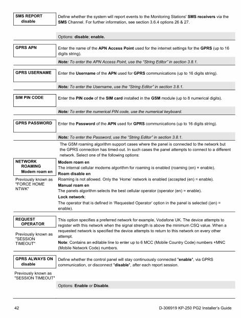
SMS REPORT disable
Define whether the system will report events to the Monitoring Stations' SMS receivers via the SMS Channel. For further information, see section 3.6.4 options 26 & 27.
Options: disable; enable. GPRS APN
Enter the name of the APN Access Point used for the internet settings for the GPRS (up to 16 digits string).
Note: To enter the APN Access Point, use the “String Editor” in section 3.8.1. GPRS USERNAME
Enter the Username of the APN used for GPRS communications (up to 16 digits string).
Note: To enter the Username, use the “String Editor” in section 3.8.1. SIM PIN CODE
Enter the PIN code of the SIM card installed in the GSM module (up to 8 numerical digits).
Note: To enter the numerical PIN code, use the numerical keyboard. GPRS PASSWORD
Enter the Password of the APN used for GPRS communications (up to 16 digits string).
Note: To enter the Password, use the “String Editor” in section 3.8.1. The GSM roaming algorithm support cases where the panel is connected to the network but
the GPRS connection has timed-out. In such cases the panel attempts to connect to a different network. Select one of the following options:
NETWORK ROAMING Modem roam en
Modem roam en The internal cellular modems algorithm for roaming is enabled (roaming (en) = enable). Roam disable en Roaming is not allowed. Only the ‘Home’ network is enabled (accepted (en) = enable). Manual roam en The panels algorithm selects the best cellular operator (operator (en) = enable). Lock network: The operator that is defined in ‘Requested Operator’ option in the panel is selected ((en) = enable).
Previously known as "FORCE HOME NTWK"
REQUEST
OPERATOR This option specifies a preferred network for example, Vodafone UK. The device attempts to register with this network when the signal strength is above the minimum CSQ value. When a requested network is specified the device attempts to return to this network on every other attempt. Note: Contains an editable line to enter up to 6 MCC (Mobile Country Code) numbers +MNC (Mobile Network Code) numbers.
Previously known as "SESSION TIMEOUT"
GPRS ALWAYS ON
disable Define whether the control panel will stay continuously connected "enable", via GPRS communication, or disconnect "disable", after each report session.
Previously known as "SESSION TIMEOUT" Options: Enable or Disable.
42 D-306919 KP-250 PG2 Installer’s Guide
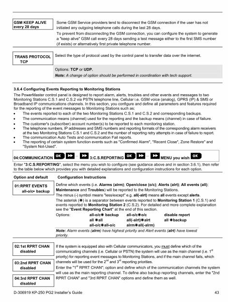
GSM KEEP ALIVE every 28 days
Some GSM Service providers tend to disconnect the GSM connection if the user has not initiated any outgoing telephone calls during the last 28 days. To prevent from disconnecting the GSM connection, you can configure the system to generate a "keep alive" GSM call every 28 days sending a test message either to the first SMS number (if exists) or alternatively first private telephone number.
TRANS PROTOCOL TCP
Select the type of protocol used by the control panel to transfer data over the internet.
Options: TCP or UDP. Note: A change of option should be performed in coordination with tech support.
3.6.4 Configuring Events Reporting to Monitoring Stations The PowerMaster control panel is designed to report alarm, alerts, troubles and other events and messages to two Monitoring Stations C.S.1 and C.S.2 via PSTN telephone line, Cellular i.e. GSM voice (analog), GPRS (IP) & SMS or Broadband IP communications channels. In this section, you configure and define all parameters and features required for the reporting of the event messages to Monitoring Stations such as: • The events reported to each of the two Monitoring Stations C.S.1 and C.S.2 and corresponding backups. • The communication means (channel) used for the reporting and the backup means (channel) in case of failure. • The customer's (subscriber) account number(s) to be reported to each monitoring station. • The telephone numbers, IP addresses and SMS numbers and reporting formats of the corresponding alarm receivers
at the two Monitoring Stations C.S.1 and C.S.2 and the number of reporting retry attempts in case of failure to report. • The communication Auto Tests and communication Fail reports. • The reporting of certain system function events such as "Confirmed Alarm", "Recent Close", Zone Restore" and
"System Not-Used".
04:COMMUNICATION ⋅⋅⋅ 3:C.S.REPORTING ⋅⋅⋅ MENU you wish
Enter "3:C.S.REPORTING", select the menu you wish to configure (see guidance above and in section 3.6.1), then refer to the table below which provides you with detailed explanations and configuration instructions for each option.
Option and default Configuration Instructions
01:RPRT EVENTS all-o/c∗ backup
Define which events (i.e. Alarms (alrm); Open/close (o/c); Alerts (alrt); All events (all); Maintenance and Troubles) will be reported to the Monitoring Stations. The minus (-) symbol means "less/except" e.g. all(-alrt) means all events except alerts. The asterisk () is a separator between events reported to Monitoring Station 1 (C.S.1) and events reported to Monitoring Station 2 (C.S.2). For detailed and more complete explanation see the "Event Reporting Chart" at the end of this section.
Options: all-o/c backup all-o/co/c disable report all all all(-alrt)alrt all backup all-o/call-o/c alrmall(-alrm) Note: Alarm events (alrm) have highest priority and Alert events (alrt) have lowest priority.
02:1st RPRT CHAN disabled
If the system is equipped also with Cellular communicators, you must define which of the communicating channels (i.e. Cellular or PSTN) the system will use as the main channel (i.e. 1st priority) for reporting event messages to Monitoring Stations, and if the main channel fails, which channels will be used for the 2nd and 3rd reporting priorities. Enter the "1st RPRT CHAN"; option and define which of the communication channels the system will use as the main reporting channel. To define also backup reporting channels, enter the "2nd RPRT CHAN" and "3rd RPRT CHAN" options and define them as well.
03:2nd RPRT CHAN
disabled 04:3rd RPRT CHAN
disabled
D-306919 KP-250 PG2 Installer’s Guide 43
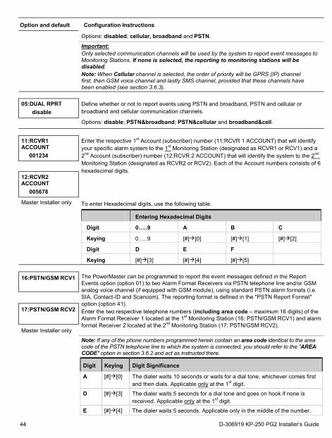
Option and default Configuration Instructions
Options: disabled; cellular, broadband and PSTN.
Important: Only selected communication channels will be used by the system to report event messages to Monitoring Stations. If none is selected, the reporting to monitoring stations will be disabled. Note: When Cellular channel is selected, the order of priority will be GPRS (IP) channel first, then GSM voice channel and lastly SMS channel, provided that these channels have been enabled (see section 3.6.3).
05:DUAL RPRT disable
Define whether or not to report events using PSTN and broadband, PSTN and cellular or broadband and cellular communication channels.
Options: disable; PSTN&broadband; PSTN&cellular and broadband&cell.
11:RCVR1 ACCOUNT
001234
Enter the respective 1st Account (subscriber) number (11:RCVR 1 ACCOUNT) that will identify your specific alarm system to the 1st Monitoring Station (designated as RCVR1 or RCV1) and a 2nd Account (subscriber) number (12:RCVR 2 ACCOUNT) that will identify the system to the 2nd Monitoring Station (designated as RCVR2 or RCV2). Each of the Account numbers consists of 6 hexadecimal digits.
12:RCVR2 ACCOUNT
005678
Master Installer only To enter Hexadecimal digits, use the following table:
Entering Hexadecimal Digits
Digit 0…..9 A B C
Keying 0…..9 [#][0] [#][1] [#][2]
Digit D E F
Keying [#][3] [#][4] [#][5]
16:PSTN/GSM RCV1
The PowerMaster can be programmed to report the event messages defined in the Report Events option (option 01) to two Alarm Format Receivers via PSTN telephone line and/or GSM analog voice channel (if equipped with GSM module), using standard PSTN alarm formats (i.e. SIA, Contact-ID and Scancom). The reporting format is defined in the "PSTN Report Format" option (option 41). Enter the two respective telephone numbers (including area code – maximum 16 digits) of the Alarm Format Receiver 1 located at the 1st Monitoring Station (16: PSTN/GSM RCV1) and alarm format Receiver 2 located at the 2nd Monitoring Station (17: PSTN/GSM RCV2).
17:PSTN/GSM RCV2
Master Installer only
Note: If any of the phone numbers programmed herein contain an area code identical to the area code of the PSTN telephone line to which the system is connected, you should refer to the "AREA CODE" option in section 3.6.2.and act as instructed there.
Digit Keying Digit Significance
A [#][0] The dialer waits 10 seconds or waits for a dial tone, whichever comes first and then dials. Applicable only at the 1st digit.
D [#][3] The dialer waits 5 seconds for a dial tone and goes on hook if none is received. Applicable only at the 1st digit.
E [#][4] The dialer waits 5 seconds. Applicable only in the middle of the number.
44 D-306919 KP-250 PG2 Installer’s Guide
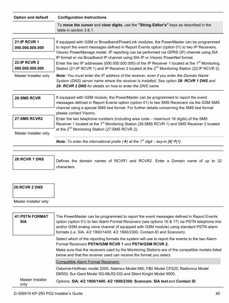
Option and default Configuration Instructions
To move the cursor and clear digits, use the "String Editor's" keys as described in the table in section 3.8.1.
21:IP RCVR 1 000.000.000.000
If equipped with GSM or Broadband/PowerLink modules, the PowerMaster can be programmed to report the event messages defined in Report Events option (option 01) to two IP Receivers, Visonic PowerManage model. IP reporting can be performed via GPRS (IP) channel using SIA IP format or via Broadband IP channel using SIA IP or Visonic PowerNet format. Enter the two IP addresses (000.000.000.000) of the IP Receiver 1 located at the 1st Monitoring Station (21:IP RCVR 1) and IP Receiver 2 located at the 2nd Monitoring Station (22:IP RCVR 2).
Note: You must enter the IP address of the receiver, even if you enter the Domain Name System (DNS) server name where the receiver is installed. See option 28: RCVR 1 DNS and 29: RCVR 2 DNS for details on how to enter the DNS name.
22:IP RCVR 2 000.000.000.000
Master Installer only
26:SMS RCVR
If equipped with GSM module, the PowerMaster can be programmed to report the event messages defined in Report Events option (option 01) to two SMS Receivers via the GSM SMS channel using a special SMS text format. For further details concerning the SMS text format please contact Visonic. Enter the two telephone numbers (including area code – maximum 16 digits).of the SMS Receiver 1 located at the 1st Monitoring Station (26:SMS RCVR 1) and SMS Receiver 2 located at the 2nd Monitoring Station (27:SMS RCVR 2).
27:SMS RCVR2
Master Installer only
Note: To enter the international prefix () at the 1st digit – key-in [#][1].
28:RCVR 1 DNS
Defines the domain names of RCVR1 and RCVR2. Enter a Domain name of up to 32 characters.
29:RCVR 2 DNS
Master Installer only
41:PSTN FORMAT SIA
The PowerMaster can be programmed to report the event messages defined in Report Events option (option 01) to two Alarm Format Receivers (see options 16 & 17) via PSTN telephone line and/or GSM analog voice channel (if equipped with GSM module) using standard PSTN alarm formats (i.e. SIA, 4/2 1900/1400; 4/2 1800/2300, Contact-ID and Scancom).
Select which of the reporting formats the system will use to report the events to the two Alarm Format Receivers PSTN/GSM RCVR 1 and PSTN/GSM RCVR 2. Make sure that the receivers used by the Monitoring Stations are of the compatible models listed below and that the receiver used can receive the format you select.
Compatible Alarm Format Receivers:
Osborne-Hoffman model 2000; Ademco Model 685; FBII Model CP220; Radionics Model D6500; Sur-Gard Model SG-MLR2-DG and Silent Knight Model 9500.
Master Installer only Options: SIA; 4/2 1900/1400; 4/2 1800/2300; Scancom; SIA text and Contact ID.
D-306919 KP-250 PG2 Installer’s Guide 45
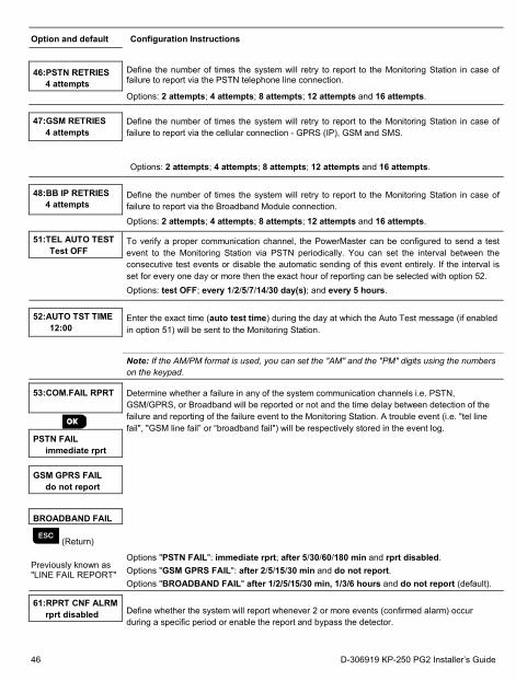
Option and default Configuration Instructions
46:PSTN RETRIES 4 attempts
Define the number of times the system will retry to report to the Monitoring Station in case of failure to report via the PSTN telephone line connection.
Options: 2 attempts; 4 attempts; 8 attempts; 12 attempts and 16 attempts.
47:GSM RETRIES 4 attempts
Define the number of times the system will retry to report to the Monitoring Station in case of failure to report via the cellular connection - GPRS (IP), GSM and SMS.
Options: 2 attempts; 4 attempts; 8 attempts; 12 attempts and 16 attempts.
48:BB IP RETRIES 4 attempts
Define the number of times the system will retry to report to the Monitoring Station in case of failure to report via the Broadband Module connection.
Options: 2 attempts; 4 attempts; 8 attempts; 12 attempts and 16 attempts.
51:TEL AUTO TEST Test OFF
To verify a proper communication channel, the PowerMaster can be configured to send a test event to the Monitoring Station via PSTN periodically. You can set the interval between the consecutive test events or disable the automatic sending of this event entirely. If the interval is set for every one day or more then the exact hour of reporting can be selected with option 52.
Options: test OFF; every 1/2/5/7/14/30 day(s); and every 5 hours.
52:AUTO TST TIME 12:00
Enter the exact time (auto test time) during the day at which the Auto Test message (if enabled in option 51) will be sent to the Monitoring Station.
Note: If the AM/PM format is used, you can set the "AM" and the "PM" digits using the numbers on the keypad.
53:COM.FAIL RPRT
Determine whether a failure in any of the system communication channels i.e. PSTN, GSM/GPRS, or Broadband will be reported or not and the time delay between detection of the failure and reporting of the failure event to the Monitoring Station. A trouble event (i.e. "tel line fail", "GSM line fail” or “broadband fail") will be respectively stored in the event log.
PSTN FAIL immediate rprt
GSM GPRS FAIL
do not report
BROADBAND FAIL
(Return)
Previously known as "LINE FAIL REPORT"
Options "PSTN FAIL": immediate rprt; after 5/30/60/180 min and rprt disabled. Options "GSM GPRS FAIL": after 2/5/15/30 min and do not report. Options "BROADBAND FAIL" after 1/2/5/15/30 min, 1/3/6 hours and do not report (default).
61:RPRT CNF ALRM
rprt disabled Define whether the system will report whenever 2 or more events (confirmed alarm) occur during a specific period or enable the report and bypass the detector.
46 D-306919 KP-250 PG2 Installer’s Guide
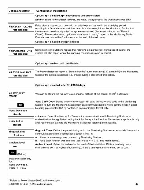
Option and default Configuration Instructions
Options: rprt disabled, rprt ena+bypass and rprt enabled
Note: In some PowerMaster variants, this menu is displayed in the Operation Mode only.
62:RECENT CLOSE
rprt disabled
False alarms may occur if users do not exit the premises within the exit delay period, resulting in a false alarm a short time later. In such cases, inform the Monitoring Station that the alarm occurred shortly after the system was armed (this event is known as "Recent Close"). The report enabled option sends a “recent closing” report to the Monitoring Station if an alarm occurs within 2 minutes from the end of the exit delay.
Options: rprt disabled and rprt enabled
63:ZONE RESTORE rprt disabled
Some Monitoring Stations require that following an alarm event from a specific zone, the system will also report when the alarming zone has restored to normal.
Options: rprt enabled and rprt disabled
64:SYST.INACTIVE rprt disabled
The PowerMaster can report a "System Inactive" event message (CID event 654) to the Monitoring Station if the system is not used (i.e. armed) during a predefined time period.
Options: rprt disabled; after 7/14/30/90 days.
65:TWO WAY VOICE
You can configure the two way voice channel settings of the control panel4, as follows: Send 2 WV Code: Define whether the system will send two-way voice code to the Monitoring Station (to turn the Monitoring Station from data communication to voice communication state) by using pre-selected SIA or Contact-ID communication format only. voice c.s.: Select the timeout for 2-way voice communication with Monitoring Stations, or enable the Monitoring Station to ring back for 2-way voice function. This option is applicable only after reporting an event to the Monitoring Station for listening and speaking.
ringback Time: Define the period during which the Monitoring Station can establish 2-way voice communication with the control panel (after 1 ring), if: A. Alarm type message was received by Monitoring Station. B. Ring Back function was selected (see “Voice <--> C.S.” sub menu above). Ambient Level: Select the ambient noise level of the installation. If it is a relatively noisy environment, set it to High (default setting). If it is a very quiet environment, set to Low.
Send 2wv code
disable voice<- ->cs
disable ringback time
1 minute ambient level
low
(Return)
Master Installer only for: Send 2wv code / voice <− −>cs /
4 Refers to PowerMaster-30 G2 with voice option. D-306919 KP-250 PG2 Installer’s Guide 47
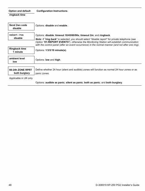
Option and default Configuration Instructions ringback time
Send 2wv code disable
Options: disable and enable.
voice<- ->cs
disable Options: disable; timeout 10/45/60/90s; timeout 2m; and ringback. Note: If "ring back" is selected, you should select "disable report" for private telephone (see Option "01:REPORT EVENTS"), otherwise the Monitoring Station will establish communication with the control panel (after an event occurrence) in the normal manner (and not after one ring).
Ringback time 1 minute Options: 1/3/5/10 minute(s).
ambient level
low Options: low and high.
66:24h ZONE RPRT both burglary
Define whether 24 hour (silent and audible) zones will function as normal 24 hour zones or as panic zones.
Applicable in UK only
Options: audible as panic; silent as panic; both as panic; and both burglary.
48 D-306919 KP-250 PG2 Installer’s Guide
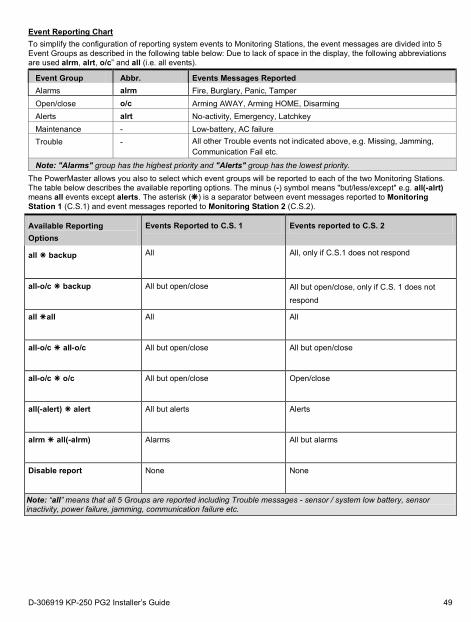
Event Reporting Chart To simplify the configuration of reporting system events to Monitoring Stations, the event messages are divided into 5 Event Groups as described in the following table below: Due to lack of space in the display, the following abbreviations are used alrm, alrt, o/c” and all (i.e. all events).
Event Group Abbr. Events Messages Reported Alarms alrm Fire, Burglary, Panic, Tamper Open/close o/c Arming AWAY, Arming HOME, Disarming Alerts alrt No-activity, Emergency, Latchkey Maintenance - Low-battery, AC failure Trouble - All other Trouble events not indicated above, e.g. Missing, Jamming,
Communication Fail etc.
Note: "Alarms" group has the highest priority and "Alerts" group has the lowest priority. The PowerMaster allows you also to select which event groups will be reported to each of the two Monitoring Stations. The table below describes the available reporting options. The minus (-) symbol means "but/less/except" e.g. all(-alrt) means all events except alerts. The asterisk () is a separator between event messages reported to Monitoring Station 1 (C.S.1) and event messages reported to Monitoring Station 2 (C.S.2).
Available Reporting Options
Events Reported to C.S. 1 Events reported to C.S. 2
all backup
All All, only if C.S.1 does not respond
all-o/c backup
All but open/close All but open/close, only if C.S. 1 does not respond
all all
All All
all-o/c all-o/c
All but open/close All but open/close
all-o/c o/c
All but open/close Open/close
all(-alert) alert
All but alerts Alerts
alrm all(-alrm)
Alarms All but alarms
Disable report
None None
Note: “all” means that all 5 Groups are reported including Trouble messages - sensor / system low battery, sensor inactivity, power failure, jamming, communication failure etc.
D-306919 KP-250 PG2 Installer’s Guide 49
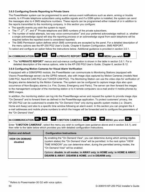
3.6.5 Configuring Events Reporting to Private Users The PowerMaster system can be programmed to send various event notifications such as alarm, arming or trouble events, to 4 Private telephone subscribers using audible signals and if a GSM option is installed, the system can send the messages also to 4 SMS telephone numbers. These reports can be programmed either instead of or in addition to the reports transmitted to the monitoring company. In this section you configure: • The specific events you wish the system to report. • The 1st, 2nd, 3rd, and 4th Private telephone and SMS numbers of the private subscribers. • The number of redial attempts, two-way voice communication5 and your preferred acknowledge method i.e. whether
a single acknowledge signal will stop the reporting process or an acknowledge signal from each telephone will be required before the reported event is considered reported.
• The SMS Permission option defines which SMS commands are accepted by the panel. For a detailed description of the menu options see the KP-250 PG2 User’s Guide, Chapter 6 System Configuration, SMS REPORT.
To select and configure an option follow the instructions below. Additional guidance is provided in section 3.6.1.
04:COMMUNICATION ⋅⋅⋅ 4:PRIVATE REPORT ⋅⋅⋅ MENU you wish
• The "4:PRIVATE REPORT" menus and sub-menus configuration is shown in the table in section 3.6.1. For a detailed description of the menus options, refer to the KP-250 PG2 User’s Guide, Chapter 6, section B.12.
3.6.6 Configuring Motion Cameras for Visual Alarm Verification If equipped with a GSM/GPRS module, the PowerMaster can communicate to Monitoring Stations (equipped with Visonic PowerManage server) via the GPRS network, also with image clips captured by Motion Cameras (models Next CAM PG2, Next-K9 CAM PG2 and TOWER CAM PG2). The Monitoring Station can use the video clips for verification of Burglary alarms detected by the Motion Cameras. The system can be configured to capture image clips also upon occurrence of Non-Burglary alarms (i.e. Fire, Duress, Emergency and Panic). The server can then forward the images to the management computer of the monitoring station or to 4 remote computers via e-mail and/or 4 mobile phones by MMS images. In addition, the monitoring station can log into the PowerManage server and request the system to provide image clips "On Demand" and to forward them as defined in the PowerManage application. To protect customers' privacy, the KP-250 PG2 can be customized to enable the "On Demand View" only during specific system modes (i.e. Disarm, Home and Away) and also to a specific time window following an alarm event. In this section you can program the 4 e-mail addresses and mobile phone numbers to which the images will be forwarded and to configure the parameters of the "On Demand View".
04:COMMUNICATION ⋅⋅⋅ 5:MOTION CAMERAS ⋅⋅⋅ MENU you wish
Enter "5:MOTION CAMERAS", select the menu you wish to configure (see guidance above and in section 3.6.1), and then refer to the table below which provides you with detailed configuration instructions.
Option and default Configuration Instructions
VIEW ON DEMAND disabled
By enabling the "On Demand View", you can determine during which arming modes (system states) the "On Demand View" will be permitted. In the next option "VIEW TIME WINDOW" you can determine when, during the permitted arming modes, the "On Demand View" will be enabled.
Options: disable; in all modes; in AWAY only; in HOME only; in HOME & AWAY; DISARM & AWAY; DISARM & HOME; and in DISARM only.
5 Refers to Powermaster-30 G2 with voice option. 50 D-306919 KP-250 PG2 Installer’s Guide
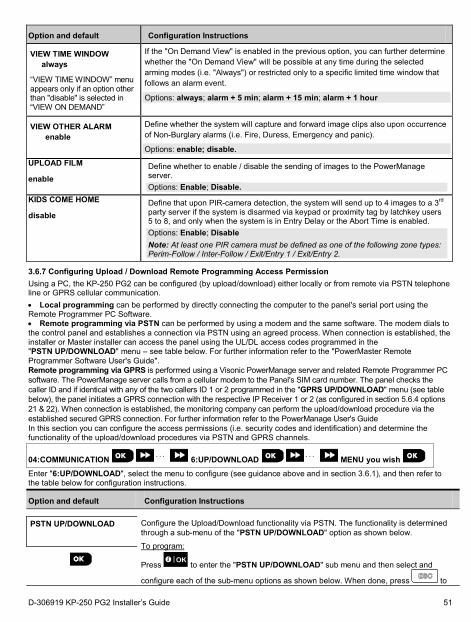
Option and default Configuration Instructions
VIEW TIME WINDOW always
“VIEW TIME WINDOW” menu appears only if an option other than "disable" is selected in “VIEW ON DEMAND”
If the "On Demand View" is enabled in the previous option, you can further determine whether the "On Demand View" will be possible at any time during the selected arming modes (i.e. "Always") or restricted only to a specific limited time window that follows an alarm event.
Options: always; alarm + 5 min; alarm + 15 min; alarm + 1 hour
VIEW OTHER ALARM enable
Define whether the system will capture and forward image clips also upon occurrence of Non-Burglary alarms (i.e. Fire, Duress, Emergency and panic).
Options: enable; disable. UPLOAD FILM enable
Define whether to enable / disable the sending of images to the PowerManage server. Options: Enable; Disable.
KIDS COME HOME disable
Define that upon PIR-camera detection, the system will send up to 4 images to a 3rd party server if the system is disarmed via keypad or proximity tag by latchkey users 5 to 8, and only when the system is in Entry Delay or the Abort Time is enabled. Options: Enable; Disable Note: At least one PIR camera must be defined as one of the following zone types: Perim-Follow / Inter-Follow / Exit/Entry 1 / Exit/Entry 2.
3.6.7 Configuring Upload / Download Remote Programming Access Permission Using a PC, the KP-250 PG2 can be configured (by upload/download) either locally or from remote via PSTN telephone line or GPRS cellular communication. • Local programming can be performed by directly connecting the computer to the panel's serial port using the Remote Programmer PC Software. • Remote programming via PSTN can be performed by using a modem and the same software. The modem dials to the control panel and establishes a connection via PSTN using an agreed process. When connection is established, the installer or Master installer can access the panel using the UL/DL access codes programmed in the "PSTN UP/DOWNLOAD" menu – see table below. For further information refer to the "PowerMaster Remote Programmer Software User's Guide". Remote programming via GPRS is performed using a Visonic PowerManage server and related Remote Programmer PC software. The PowerManage server calls from a cellular modem to the Panel's SIM card number. The panel checks the caller ID and if identical with any of the two callers ID 1 or 2 programmed in the "GPRS UP/DOWNLOAD" menu (see table below), the panel initiates a GPRS connection with the respective IP Receiver 1 or 2 (as configured in section 5.6.4 options 21 & 22). When connection is established, the monitoring company can perform the upload/download procedure via the established secured GPRS connection. For further information refer to the PowerManage User's Guide In this section you can configure the access permissions (i.e. security codes and identification) and determine the functionality of the upload/download procedures via PSTN and GPRS channels.
04:COMMUNICATION ⋅ ⋅ ⋅ 6:UP/DOWNLOAD ⋅ ⋅ ⋅ MENU you wish
Enter "6:UP/DOWNLOAD", select the menu to configure (see guidance above and in section 3.6.1), and then refer to the table below for configuration instructions.
Option and default Configuration Instructions
PSTN UP/DOWNLOAD Configure the Upload/Download functionality via PSTN. The functionality is determined
through a sub-menu of the "PSTN UP/DOWNLOAD" option as shown below.
To program:
Press to enter the "PSTN UP/DOWNLOAD" sub menu and then select and
configure each of the sub-menu options as shown below. When done, press to
D-306919 KP-250 PG2 Installer’s Guide 51
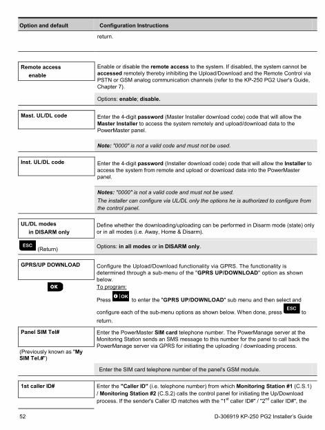
Option and default Configuration Instructions
return.
Remote access
enable Enable or disable the remote access to the system. If disabled, the system cannot be accessed remotely thereby inhibiting the Upload/Download and the Remote Control via PSTN or GSM analog communication channels (refer to the KP-250 PG2 User's Guide, Chapter 7).
Options: enable; disable.
Mast. UL/DL code
Enter the 4-digit password (Master Installer download code) code that will allow the Master Installer to access the system remotely and upload/download data to the PowerMaster panel.
Note: "0000" is not a valid code and must not be used.
Inst. UL/DL code
Enter the 4-digit password (Installer download code) code that will allow the Installer to access the system from remote and upload or download data into the PowerMaster panel.
Notes: "0000" is not a valid code and must not be used. The installer can configure via UL/DL only the options he is authorized to configure from the control panel.
UL/DL modes
in DISARM only Define whether the downloading/uploading can be performed in Disarm mode (state) only or in all modes (i.e. Away, Home & Disarm).
(Return) Options: in all modes or in DISARM only.
GPRS/UP DOWNLOAD
Configure the Upload/Download functionality via GPRS. The functionality is determined through a sub-menu of the "GPRS UP/DOWNLOAD" option as shown below. To program:
Press to enter the "GPRS UP/DOWNLOAD" sub menu and then select and
configure each of the sub-menu options as shown below. When done, press to return.
Panel SIM Tel#
Enter the PowerMaster SIM card telephone number. The PowerManage server at the Monitoring Station sends an SMS message to this number for the panel to call back the PowerManage server via GPRS for initiating the uploading / downloading process.
(Previously known as "My SIM Tel.#")
Enter the SIM card telephone number of the panel's GSM module.
1st caller ID#
Enter the "Caller ID" (i.e. telephone number) from which Monitoring Station #1 (C.S.1) / Monitoring Station #2 (C.S.2) calls the control panel for initiating the Up/Download process. If the sender's Caller ID matches with the "1st caller ID#" / "2nd caller ID#", the
52 D-306919 KP-250 PG2 Installer’s Guide
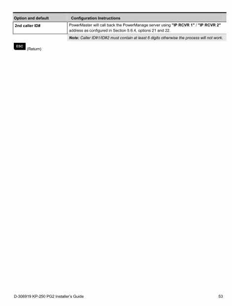
Option and default Configuration Instructions
2nd caller ID#
PowerMaster will call back the PowerManage server using "IP RCVR 1" / "IP RCVR 2" address as configured in Section 5.6.4, options 21 and 22.
Note: Caller ID#1/ID#2 must contain at least 6 digits otherwise the process will not work.
(Return)
D-306919 KP-250 PG2 Installer’s Guide 53
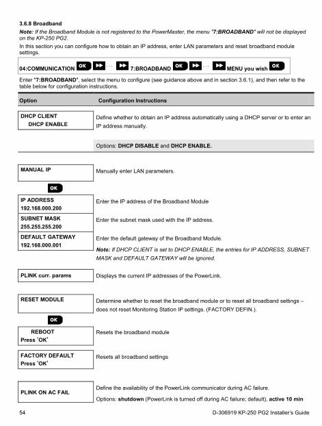
3.6.8 Broadband Note: If the Broadband Module is not registered to the PowerMaster, the menu "7:BROADBAND" will not be displayed on the KP-250 PG2. In this section you can configure how to obtain an IP address, enter LAN parameters and reset broadband module settings.
04:COMMUNICATION ⋅ ⋅ ⋅ 7:BROADBAND ⋅ ⋅ ⋅ MENU you wish
Enter "7:BROADBAND", select the menu to configure (see guidance above and in section 3.6.1), and then refer to the table below for configuration instructions.
Option Configuration Instructions
DHCP CLIENT DHCP ENABLE
Define whether to obtain an IP address automatically using a DHCP server or to enter an IP address manually.
Options: DHCP DISABLE and DHCP ENABLE.
MANUAL IP
Manually enter LAN parameters.
IP ADDRESS 192.168.000.200
Enter the IP address of the Broadband Module
SUBNET MASK 255.255.255.200
Enter the subnet mask used with the IP address.
DEFAULT GATEWAY 192.168.000.001
Enter the default gateway of the Broadband Module.
Note: If DHCP CLIENT is set to DHCP ENABLE, the entries for IP ADDRESS, SUBNET MASK and DEFAULT GATEWAY will be ignored.
PLINK curr. params Displays the current IP addresses of the PowerLink.
RESET MODULE
Determine whether to reset the broadband module or to reset all broadband settings – does not reset Monitoring Station IP settings. (FACTORY DEFIN.).
REBOOT
Press ‘OK‘ Resets the broadband module
FACTORY DEFAULT Press ‘OK‘
Resets all broadband settings
PLINK ON AC FAIL Define the availability of the PowerLink communicator during AC failure.
Options: shutdown (PowerLink is turned off during AC failure; default), active 10 min
54 D-306919 KP-250 PG2 Installer’s Guide
Option Configuration Instructions
(PowerLink is turned off if AC failure duration is longer than 10 minutes), or active (PowerLink will always be active).
Note: Keeping the PowerLink communicator active during AC failure reduces battery backup time significantly.
D-306919 KP-250 PG2 Installer’s Guide 55
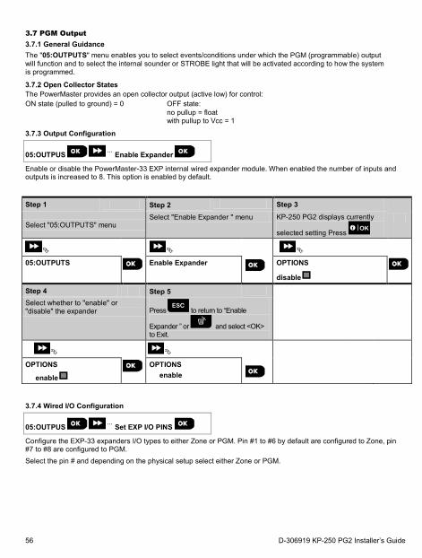
3.7 PGM Output 3.7.1 General Guidance The "05:OUTPUTS" menu enables you to select events/conditions under which the PGM (programmable) output will function and to select the internal sounder or STROBE light that will be activated according to how the system is programmed.
3.7.2 Open Collector States The PowerMaster provides an open collector output (active low) for control: ON state (pulled to ground) = 0 OFF state:
no pullup = float with pullup to Vcc = 1
3.7.3 Output Configuration
05:OUTPUS ⋅⋅⋅ Enable Expander
Enable or disable the PowerMaster-33 EXP internal wired expander module. When enabled the number of inputs and outputs is increased to 8. This option is enabled by default.
Step 1 Step 2 Step 3
Select "05:OUTPUTS" menu
Select "Enable Expander " menu KP-250 PG2 displays currently
selected setting Press
05:OUTPUTS
Enable Expander
OPTIONS
disable
Step 4 Step 5 Select whether to "enable" or "disable" the expander Press to return to “Enable
Expander ” or and select <OK> to Exit.
OPTIONS
enable
OPTIONS enable
3.7.4 Wired I/O Configuration
05:OUTPUS ⋅⋅⋅ Set EXP I/O PINS
Configure the EXP-33 expanders I/O types to either Zone or PGM. Pin #1 to #6 by default are configured to Zone, pin #7 to #8 are configured to PGM. Select the pin # and depending on the physical setup select either Zone or PGM.
56 D-306919 KP-250 PG2 Installer’s Guide
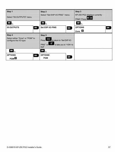
Step 1 Step 2 Step 3
Select "05:OUTPUTS" menu
Select "Set EXP I/O PINS " menu KP-250 PG2 displays currently
PIN#1 Press
05:OUTPUTS
Set EXP I/O PINS
OPTIONS
Zone
Step 4 Step 5 Select either "Zone" or "PGM" to configure the I/O type Press to return to “Set EXP I/O
PINS ” or to take you to “<OK> to Exit"
OPTIONS
PGM
OPTIONS PGM
D-306919 KP-250 PG2 Installer’s Guide 57
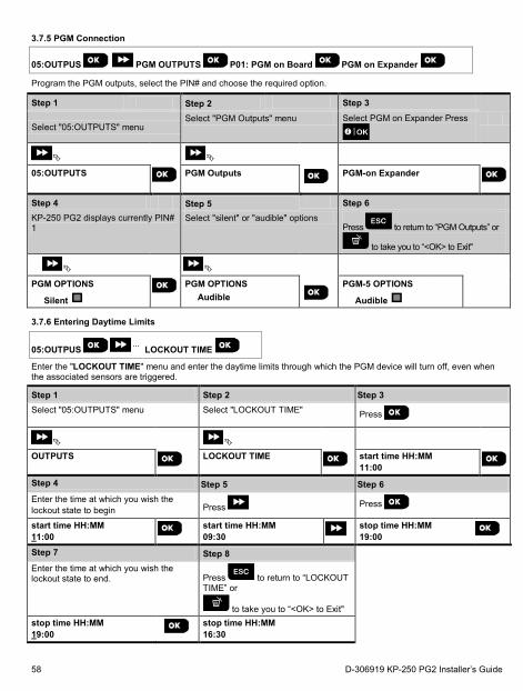
3.7.5 PGM Connection
05:OUTPUS PGM OUTPUTS P01: PGM on Board PGM on Expander
Program the PGM outputs, select the PIN# and choose the required option.
Step 1 Step 2 Step 3
Select "05:OUTPUTS" menu
Select "PGM Outputs" menu Select PGM on Expander Press
05:OUTPUTS
PGM Outputs
PGM-on Expander
Step 4 Step 5 Step 6 KP-250 PG2 displays currently PIN# 1
Select "silent" or "audible" options Press to return to “PGM Outputs” or
to take you to “<OK> to Exit"
PGM OPTIONS
Silent
PGM OPTIONS Audible
PGM-5 OPTIONS
Audible
3.7.6 Entering Daytime Limits
05:OUTPUS ⋅⋅⋅ LOCKOUT TIME
Enter the "LOCKOUT TIME" menu and enter the daytime limits through which the PGM device will turn off, even when the associated sensors are triggered.
Step 1 Step 2 Step 3 Select "05:OUTPUTS" menu Select "LOCKOUT TIME" Press
OUTPUTS
LOCKOUT TIME
start time HH:MM 11:00
Step 4 Step 5 Step 6 Enter the time at which you wish the lockout state to begin
Press Press
start time HH:MM 11:00
start time HH:MM 09:30
stop time HH:MM 19:00
Step 7 Step 8 Enter the time at which you wish the lockout state to end. Press to return to “LOCKOUT
TIME” or
to take you to “<OK> to Exit"
stop time HH:MM 19:00
stop time HH:MM 16:30
58 D-306919 KP-250 PG2 Installer’s Guide
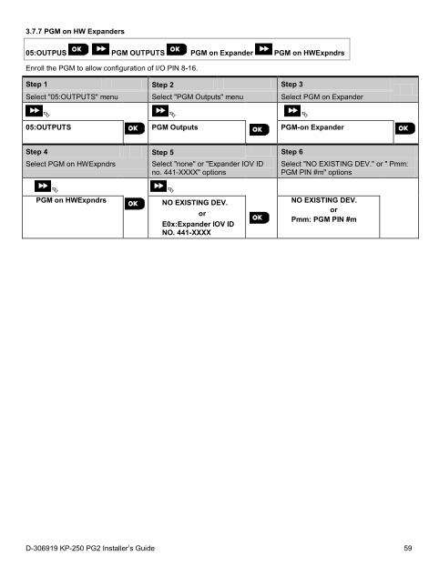
3.7.7 PGM on HW Expanders
05:OUTPUS PGM OUTPUTS PGM on Expander PGM on HWExpndrs
Enroll the PGM to allow configuration of I/O PIN 8-16.
Step 1 Step 2 Step 3
Select "05:OUTPUTS" menu Select "PGM Outputs" menu Select PGM on Expander
05:OUTPUTS
PGM Outputs
PGM-on Expander
Step 4 Step 5 Step 6
Select PGM on HWExpndrs Select "none" or "Expander IOV ID no. 441-XXXX" options
Select "NO EXISTING DEV." or " Pmm: PGM PIN #m" options
PGM on HWExpndrs
NO EXISTING DEV. or
E0x:Expander IOV ID NO. 441-XXXX
NO EXISTING DEV. or
Pmm: PGM PIN #m
D-306919 KP-250 PG2 Installer’s Guide 59
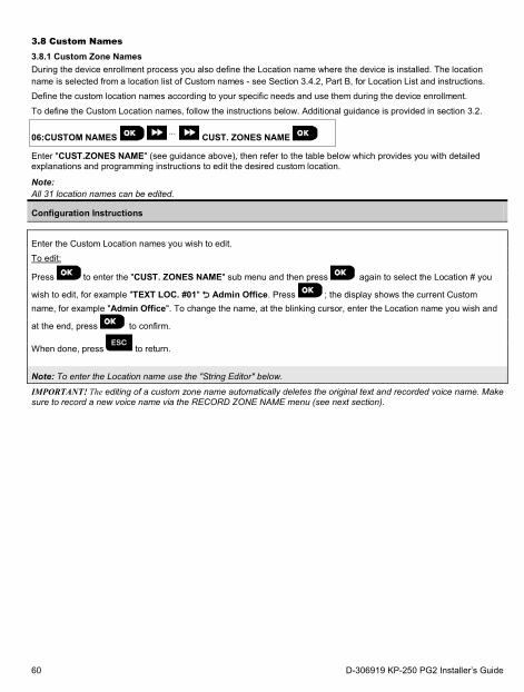
3.8 Custom Names 3.8.1 Custom Zone Names During the device enrollment process you also define the Location name where the device is installed. The location name is selected from a location list of Custom names - see Section 3.4.2, Part B, for Location List and instructions. Define the custom location names according to your specific needs and use them during the device enrollment.
To define the Custom Location names, follow the instructions below. Additional guidance is provided in section 3.2.
06:CUSTOM NAMES ⋅⋅⋅ CUST. ZONES NAME
Enter "CUST.ZONES NAME" (see guidance above), then refer to the table below which provides you with detailed explanations and programming instructions to edit the desired custom location.
Note: All 31 location names can be edited.
Configuration Instructions
Enter the Custom Location names you wish to edit. To edit:
Press to enter the "CUST. ZONES NAME" sub menu and then press again to select the Location # you
wish to edit, for example "TEXT LOC. #01" Admin Office. Press ; the display shows the current Custom name, for example "Admin Office". To change the name, at the blinking cursor, enter the Location name you wish and
at the end, press to confirm.
When done, press to return.
Note: To enter the Location name use the "String Editor" below.
IMPORTANT! The editing of a custom zone name automatically deletes the original text and recorded voice name. Make sure to record a new voice name via the RECORD ZONE NAME menu (see next section).
60 D-306919 KP-250 PG2 Installer’s Guide
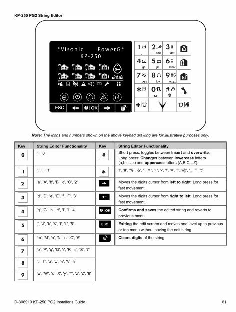
KP-250 PG2 String Editor
Note: The icons and numbers shown on the above keypad drawing are for illustrative purposes only.
Key String Editor Functionality Key String Editor Functionality
' ', '0'
Short press: toggles between Insert and overwrite. Long press: Changes between lowercase letters (a,b,c…z) and uppercase letters (A,B,C…Z).
'.', ',', '1'
'!', '#', '%', '&', ''', '∗', '+', '-', '/', '=', ' '̂, '@', '˽', '”', “:”
'a', 'A', 'b', 'B', 'c', 'C', '2' Moves the digits cursor from left to right. Long press for
fast movement.
'd', 'D', 'e', 'E', 'f', 'F', '3'
Moves the digits cursor from right to left. Long press for fast movement.
'g', 'G', 'h', 'H', 'i', 'I', '4'
Confirms and saves the edited string and reverts to previous menu.
'j', 'J', 'k', 'K', 'l', 'L', '5'
Exiting the edit screen and moves one level up to previous or top menu without saving the edit string.
'm', 'M', 'n', 'N', 'o', 'O', '6'
Clears digits of the string
'p', 'P', 'q', 'Q', 'r', 'R', 's', 'S', '7'
't', 'T', 'u', 'U', 'v', 'V', '8'
'w', 'W', 'x', 'X', 'y', 'Y', 'z', 'Z', '9'
D-306919 KP-250 PG2 Installer’s Guide 61
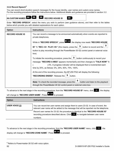
3.8.2 Record Speech6 You can record short-duration speech messages for the house identity, user names and custom zone names. For the recording procedure follow the instructions below. Additional details and guidance are provided in section 3.2.
06:CUSTOM NAMES ⋅⋅⋅ RECORD HOUSE ID
Enter "RECORD SPEECH", select the menu you wish to perform (see guidance above), and then refer to the tables below which provide you with detailed explanations for each option.
Option Instructions
RECORD HOUSE ID
You can record a message to be announced automatically when events are reported to private telephones.
While in "RECORD SPEECH", press ; the display now reads "RECORD HOUSE
ID" "REC-<2> PLAY-<5>" (this means, press the button to record and the
button to play recording through the PowerMaster-30 G2 control panel or external voice box).
To initiate the recording procedure, press the button continuously to record your
message; "RECORD A MSG" appears momentarily and then changes to "TALK NOW" ( ) 0%. A progress indicator will be displayed that is incremented each time by 25%, as follows: 0%, 25%, 50%, 75%, 100%.
At the end of the recording process, the KP-250 PG2 will display the following:
"RECORDING ENDED". Release the button.
Note: To check the recorded message, press the button and listen to the playback through the PowerMaster-30 G2 control panel or external voice box.
To advance to the next stage in the recording procedure; from the "RECORD HOUSE ID" menu, click ; the display
will change to “RECORD USER NAME”. Press to proceed.
Option Instructions
USER VOICE 23
You can record ten user names and assign them to users 23-32. In case of event, the relevant user name will be added to the message that will be reported via the telephone.
Record user names for 23-32; the procedure is identical to the "RECORD HOUSE ID" recording procedure described above. Click to navigate between user name
numbers.
To advance to the next stage in the recording procedure; from the "RECORD USER NAME" menu, click ; the
display will change to “RECORD ZONE NAME”. Press to proceed.
6 Refers to Powermaster-30 G2 with voice option. 62 D-306919 KP-250 PG2 Installer’s Guide
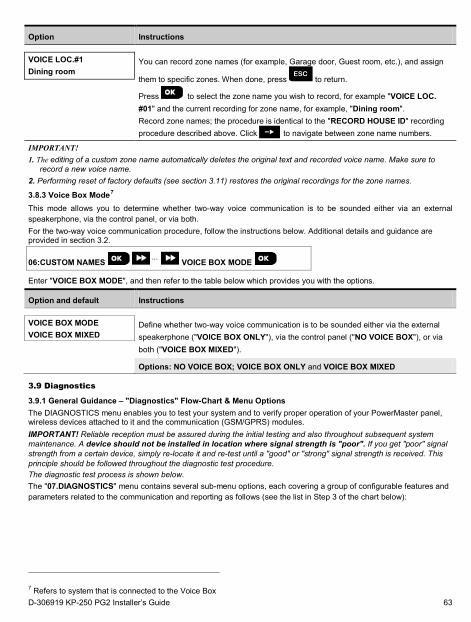
Option Instructions
VOICE LOC.#1 Dining room
You can record zone names (for example, Garage door, Guest room, etc.), and assign
them to specific zones. When done, press to return.
Press to select the zone name you wish to record, for example "VOICE LOC. #01" and the current recording for zone name, for example, "Dining room". Record zone names; the procedure is identical to the "RECORD HOUSE ID" recording procedure described above. Click to navigate between zone name numbers.
IMPORTANT! 1. The editing of a custom zone name automatically deletes the original text and recorded voice name. Make sure to
record a new voice name. 2. Performing reset of factory defaults (see section 3.11) restores the original recordings for the zone names.
3.8.3 Voice Box Mode7 This mode allows you to determine whether two-way voice communication is to be sounded either via an external speakerphone, via the control panel, or via both. For the two-way voice communication procedure, follow the instructions below. Additional details and guidance are provided in section 3.2.
06:CUSTOM NAMES ⋅⋅⋅ VOICE BOX MODE
Enter "VOICE BOX MODE", and then refer to the table below which provides you with the options.
Option and default Instructions
VOICE BOX MODE VOICE BOX MIXED
Define whether two-way voice communication is to be sounded either via the external speakerphone ("VOICE BOX ONLY"), via the control panel ("NO VOICE BOX"), or via both ("VOICE BOX MIXED").
Options: NO VOICE BOX; VOICE BOX ONLY and VOICE BOX MIXED
3.9 Diagnostics
3.9.1 General Guidance – "Diagnostics" Flow-Chart & Menu Options The DIAGNOSTICS menu enables you to test your system and to verify proper operation of your PowerMaster panel, wireless devices attached to it and the communication (GSM/GPRS) modules. IMPORTANT! Reliable reception must be assured during the initial testing and also throughout subsequent system maintenance. A device should not be installed in location where signal strength is "poor". If you get "poor" signal strength from a certain device, simply re-locate it and re-test until a "good" or "strong" signal strength is received. This principle should be followed throughout the diagnostic test procedure. The diagnostic test process is shown below. The "07.DIAGNOSTICS" menu contains several sub-menu options, each covering a group of configurable features and parameters related to the communication and reporting as follows (see the list in Step 3 of the chart below):
7 Refers to system that is connected to the Voice Box D-306919 KP-250 PG2 Installer’s Guide 63
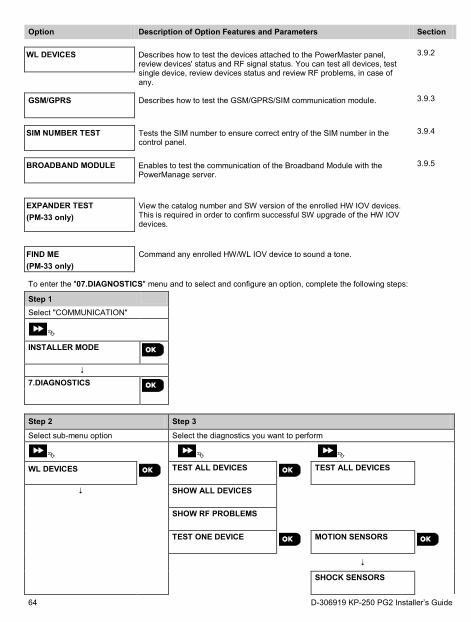
Option Description of Option Features and Parameters Section
WL DEVICES
Describes how to test the devices attached to the PowerMaster panel, review devices' status and RF signal status. You can test all devices, test single device, review devices status and review RF problems, in case of any.
3.9.2
GSM/GPRS
Describes how to test the GSM/GPRS/SIM communication module. 3.9.3
SIM NUMBER TEST
Tests the SIM number to ensure correct entry of the SIM number in the control panel.
3.9.4
BROADBAND MODULE
Enables to test the communication of the Broadband Module with the PowerManage server.
3.9.5
EXPANDER TEST (PM-33 only)
View the catalog number and SW version of the enrolled HW IOV devices. This is required in order to confirm successful SW upgrade of the HW IOV devices.
FIND ME (PM-33 only)
Command any enrolled HW/WL IOV device to sound a tone.
To enter the "07.DIAGNOSTICS" menu and to select and configure an option, complete the following steps:
Step 1
Select "COMMUNICATION"
INSTALLER MODE
7.DIAGNOSTICS
Step 2 Step 3
Select sub-menu option Select the diagnostics you want to perform
WL DEVICES
TEST ALL DEVICES
TEST ALL DEVICES
SHOW ALL DEVICES
SHOW RF PROBLEMS
TEST ONE DEVICE
MOTION SENSORS
SHOCK SENSORS
64 D-306919 KP-250 PG2 Installer’s Guide
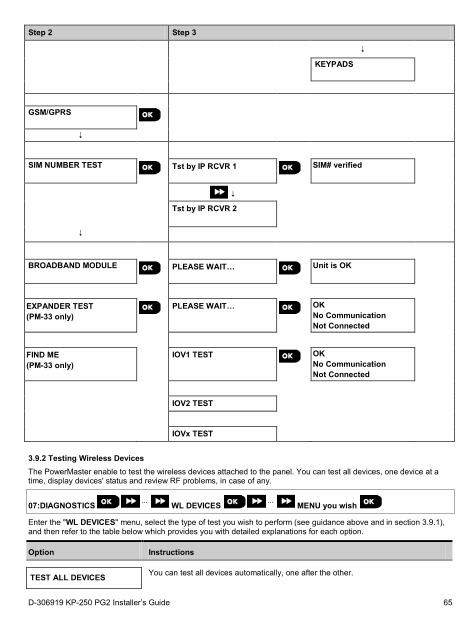
Step 2 Step 3
KEYPADS
GSM/GPRS
SIM NUMBER TEST
Tst by IP RCVR 1
SIM# verified
Tst by IP RCVR 2
BROADBAND MODULE
PLEASE WAIT…
Unit is OK
EXPANDER TEST (PM-33 only)
PLEASE WAIT…
OK No Communication Not Connected
FIND ME (PM-33 only)
IOV1 TEST
OK No Communication Not Connected
IOV2 TEST
IOVx TEST
3.9.2 Testing Wireless Devices The PowerMaster enable to test the wireless devices attached to the panel. You can test all devices, one device at a time, display devices' status and review RF problems, in case of any.
07:DIAGNOSTICS ⋅⋅⋅ WL DEVICES ⋅⋅⋅ MENU you wish
Enter the "WL DEVICES" menu, select the type of test you wish to perform (see guidance above and in section 3.9.1), and then refer to the table below which provides you with detailed explanations for each option.
Option Instructions
TEST ALL DEVICES You can test all devices automatically, one after the other.
D-306919 KP-250 PG2 Installer’s Guide 65
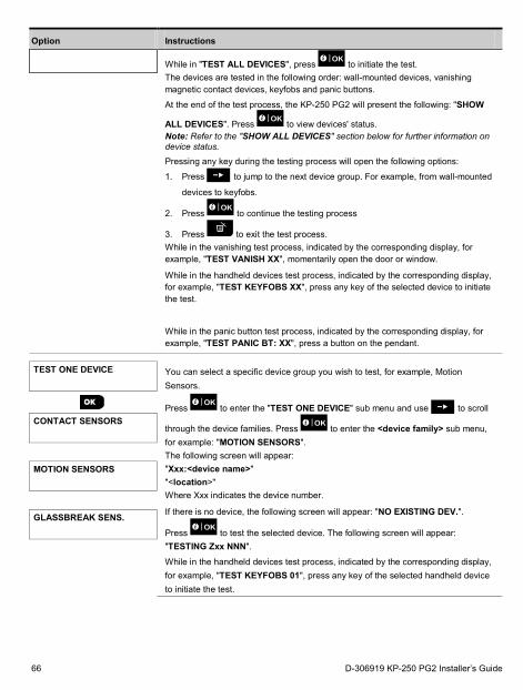
Option Instructions
While in "TEST ALL DEVICES", press to initiate the test. The devices are tested in the following order: wall-mounted devices, vanishing magnetic contact devices, keyfobs and panic buttons.
At the end of the test process, the KP-250 PG2 will present the following: "SHOW
ALL DEVICES". Press to view devices' status. Note: Refer to the "SHOW ALL DEVICES" section below for further information on device status.
Pressing any key during the testing process will open the following options:
1. Press to jump to the next device group. For example, from wall-mounted
devices to keyfobs.
2. Press to continue the testing process
3. Press to exit the test process. While in the vanishing test process, indicated by the corresponding display, for example, "TEST VANISH XX", momentarily open the door or window.
While in the handheld devices test process, indicated by the corresponding display, for example, "TEST KEYFOBS XX", press any key of the selected device to initiate the test.
While in the panic button test process, indicated by the corresponding display, for example, "TEST PANIC BT: XX", press a button on the pendant.
TEST ONE DEVICE
You can select a specific device group you wish to test, for example, Motion Sensors.
Press to enter the "TEST ONE DEVICE" sub menu and use to scroll
through the device families. Press to enter the <device family> sub menu, for example: "MOTION SENSORS". The following screen will appear: "Xxx:<device name>" "<location>" Where Xxx indicates the device number.
If there is no device, the following screen will appear: "NO EXISTING DEV.".
Press to test the selected device. The following screen will appear: "TESTING Zxx NNN".
While in the handheld devices test process, indicated by the corresponding display, for example, "TEST KEYFOBS 01", press any key of the selected handheld device to initiate the test.
CONTACT SENSORS
MOTION SENSORS
GLASSBREAK SENS.
66 D-306919 KP-250 PG2 Installer’s Guide
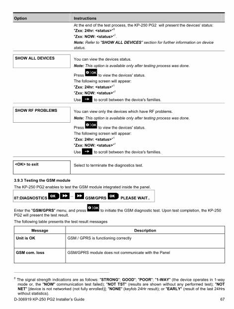
Option Instructions At the end of the test process, the KP-250 PG2 will present the devices' status: "Zxx: 24hr: <status>"8 "Zxx: NOW: <status>"1. Note: Refer to "SHOW ALL DEVICES" section for further information on device status.
SHOW ALL DEVICES
You can view the devices status. Note: This option is available only after testing process was done.
Press to view the devices' status. The following screen will appear: "Zxx: 24hr: <status>"1 "Zxx: NOW: <status>"1
Use to scroll between the device's families.
SHOW RF PROBLEMS
You can view only the devices which have RF problems. Note: This option is available only after testing process was done.
Press to view the devices' status. The following screen will appear: "Zxx: 24hr: <status>"1 "Zxx: NOW: <status>"1
Use to scroll between the device's families.
<OK> to exit
Select to terminate the diagnostics test.
3.9.3 Testing the GSM module The KP-250 PG2 enables to test the GSM module integrated inside the panel.
07:DIAGNOSTICS ⋅⋅⋅ GSM/GPRS PLEASE WAIT..
Enter the "GSM/GPRS" menu, and press to initiate the GSM diagnostic test. Upon test completion, the KP-250 PG2 will present the test result. The following table presents the test result messages
Message Description
Unit is OK
GSM / GPRS is functioning correctly
GSM com. loss
GSM/GPRS module does not communicate with the Panel
8 The signal strength indications are as follows: "STRONG"; GOOD"; "POOR"; "1-WAY" (the device operates in 1-way mode or, the "NOW" communication test failed); "NOT TST" (results are shown without any performed test); "NOT NET" [device is not networked (not fully enrolled)]; "NONE" (keyfob 24Hr result); or "EARLY" (result of the last 24Hrs without statistics).
D-306919 KP-250 PG2 Installer’s Guide 67
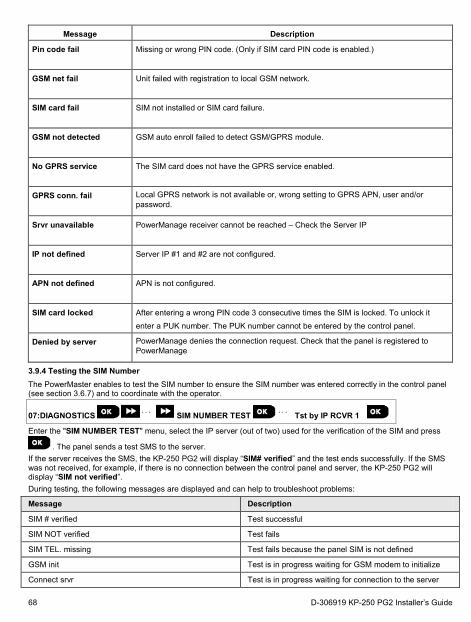
Message Description
Pin code fail
Missing or wrong PIN code. (Only if SIM card PIN code is enabled.)
GSM net fail
Unit failed with registration to local GSM network.
SIM card fail
SIM not installed or SIM card failure.
GSM not detected
GSM auto enroll failed to detect GSM/GPRS module.
No GPRS service
The SIM card does not have the GPRS service enabled.
GPRS conn. fail
Local GPRS network is not available or, wrong setting to GPRS APN, user and/or password.
Srvr unavailable
PowerManage receiver cannot be reached – Check the Server IP
IP not defined
Server IP #1 and #2 are not configured.
APN not defined
APN is not configured.
SIM card locked
After entering a wrong PIN code 3 consecutive times the SIM is locked. To unlock it enter a PUK number. The PUK number cannot be entered by the control panel.
Denied by server
PowerManage denies the connection request. Check that the panel is registered to PowerManage
3.9.4 Testing the SIM Number The PowerMaster enables to test the SIM number to ensure the SIM number was entered correctly in the control panel (see section 3.6.7) and to coordinate with the operator.
07:DIAGNOSTICS ⋅ ⋅ ⋅ SIM NUMBER TEST ⋅ ⋅ ⋅ Tst by IP RCVR 1
Enter the "SIM NUMBER TEST" menu, select the IP server (out of two) used for the verification of the SIM and press
. The panel sends a test SMS to the server. If the server receives the SMS, the KP-250 PG2 will display “SIM# verified” and the test ends successfully. If the SMS was not received, for example, if there is no connection between the control panel and server, the KP-250 PG2 will display “SIM not verified”. During testing, the following messages are displayed and can help to troubleshoot problems:
Message Description
SIM # verified Test successful
SIM NOT verified Test fails
SIM TEL. missing Test fails because the panel SIM is not defined
GSM init Test is in progress waiting for GSM modem to initialize
Connect srvr Test is in progress waiting for connection to the server
68 D-306919 KP-250 PG2 Installer’s Guide
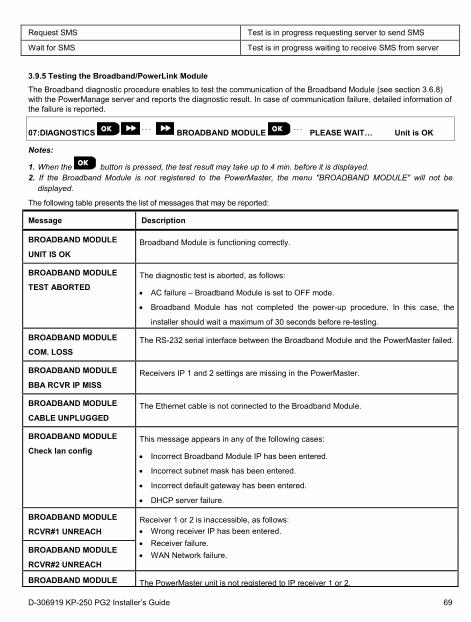
Request SMS Test is in progress requesting server to send SMS
Wait for SMS Test is in progress waiting to receive SMS from server
3.9.5 Testing the Broadband/PowerLink Module The Broadband diagnostic procedure enables to test the communication of the Broadband Module (see section 3.6.8) with the PowerManage server and reports the diagnostic result. In case of communication failure, detailed information of the failure is reported.
07:DIAGNOSTICS ⋅ ⋅ ⋅ BROADBAND MODULE ⋅ ⋅ ⋅ PLEASE WAIT… Unit is OK
Notes:
1. When the button is pressed, the test result may take up to 4 min. before it is displayed. 2. If the Broadband Module is not registered to the PowerMaster, the menu "BROADBAND MODULE" will not be
displayed.
The following table presents the list of messages that may be reported:
Message Description
BROADBAND MODULE
UNIT IS OK Broadband Module is functioning correctly.
BROADBAND MODULE
TEST ABORTED The diagnostic test is aborted, as follows:
• AC failure – Broadband Module is set to OFF mode.
• Broadband Module has not completed the power-up procedure. In this case, the
installer should wait a maximum of 30 seconds before re-testing.
BROADBAND MODULE
COM. LOSS The RS-232 serial interface between the Broadband Module and the PowerMaster failed.
BROADBAND MODULE
BBA RCVR IP MISS Receivers IP 1 and 2 settings are missing in the PowerMaster.
BROADBAND MODULE
CABLE UNPLUGGED The Ethernet cable is not connected to the Broadband Module.
BROADBAND MODULE
Check lan config This message appears in any of the following cases:
• Incorrect Broadband Module IP has been entered.
• Incorrect subnet mask has been entered.
• Incorrect default gateway has been entered.
• DHCP server failure.
BROADBAND MODULE
RCVR#1 UNREACH Receiver 1 or 2 is inaccessible, as follows: • Wrong receiver IP has been entered. • Receiver failure. • WAN Network failure. BROADBAND MODULE
RCVR#2 UNREACH
BROADBAND MODULE The PowerMaster unit is not registered to IP receiver 1 or 2.
D-306919 KP-250 PG2 Installer’s Guide 69
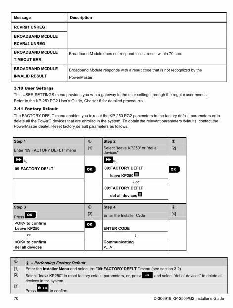
Message Description
RCVR#1 UNREG
BROADBAND MODULE
RCVR#2 UNREG
BROADBAND MODULE
TIMEOUT ERR. Broadband Module does not respond to test result within 70 sec.
BROADBAND MODULE
INVALID RESULT Broadband Module responds with a result code that is not recognized by the
PowerMaster.
3.10 User Settings This USER SETTINGS menu provides you with a gateway to the user settings through the regular user menus. Refer to the KP-250 PG2 User’s Guide, Chapter 6 for detailed procedures.
3.11 Factory Default The FACTORY DEFLT menu enables you to reset the KP-250 PG2 parameters to the factory default parameters or to delete all the PowerG devices that are enrolled in the system. To obtain the relevant parameters defaults, contact the PowerMaster dealer. Reset factory default parameters as follows:
Step 1 Step 2
Enter “09:FACTORY DEFLT” menu [1] Select "leave KP250" or "del all devices"
[2]
09:FACTORY DEFLT
09:FACTORY DEFLT
leave KP250
or 09:FACTORY DEFLT
del all devices
Step 3 Step 4
Press [3] Enter the Installer Code [4]
<OK> to confirm Leave KP250
ENTER CODE
or <OK> to confirm del all devices
Communicating <…>
– Performing Factory Default
[1] Enter the Installer Menu and select the "09:FACTORY DEFLT " menu (see section 3.2). [2] Select “leave KP250” to reset factory default parameters, or, press and select “del all devices” to delete all
devices in the system. [3]
Press to confirm.
70 D-306919 KP-250 PG2 Installer’s Guide
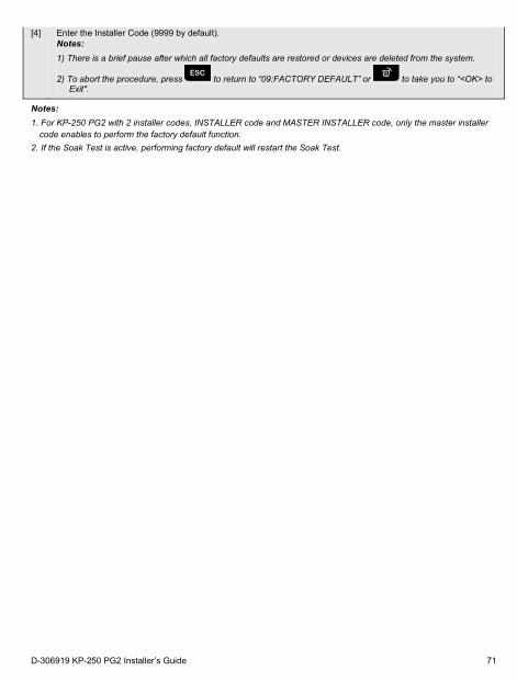
[4] Enter the Installer Code (9999 by default).
Notes: 1) There is a brief pause after which all factory defaults are restored or devices are deleted from the system.
2) To abort the procedure, press to return to “09:FACTORY DEFAULT” or to take you to “<OK> to Exit".
Notes: 1. For KP-250 PG2 with 2 installer codes, INSTALLER code and MASTER INSTALLER code, only the master installer
code enables to perform the factory default function. 2. If the Soak Test is active, performing factory default will restart the Soak Test.
D-306919 KP-250 PG2 Installer’s Guide 71
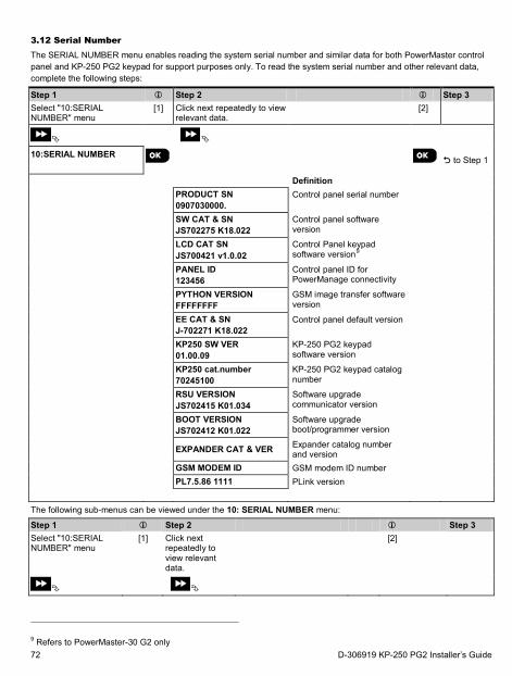
3.12 Serial Number The SERIAL NUMBER menu enables reading the system serial number and similar data for both PowerMaster control panel and KP-250 PG2 keypad for support purposes only. To read the system serial number and other relevant data, complete the following steps:
Step 1 Step 2 Step 3 Select "10:SERIAL NUMBER" menu
[1] Click next repeatedly to view relevant data.
[2]
10:SERIAL NUMBER
to Step 1
Definition PRODUCT SN
0907030000. Control panel serial number
SW CAT & SN JS702275 K18.022
Control panel software version
LCD CAT SN JS700421 v1.0.02
Control Panel keypad software version9
PANEL ID 123456
Control panel ID for PowerManage connectivity
PYTHON VERSION FFFFFFFF
GSM image transfer software version
EE CAT & SN J-702271 K18.022
Control panel default version
KP250 SW VER 01.00.09
KP-250 PG2 keypad software version
KP250 cat.number 70245100
KP-250 PG2 keypad catalog number
RSU VERSION JS702415 K01.034
Software upgrade communicator version
BOOT VERSION JS702412 K01.022
Software upgrade boot/programmer version
EXPANDER CAT & VER Expander catalog number and version
GSM MODEM ID GSM modem ID number PL7.5.86 1111 PLink version The following sub-menus can be viewed under the 10: SERIAL NUMBER menu:
Step 1 Step 2 Step 3 Select "10:SERIAL NUMBER" menu
[1] Click next repeatedly to view relevant data.
[2]
9 Refers to PowerMaster-30 G2 only 72 D-306919 KP-250 PG2 Installer’s Guide
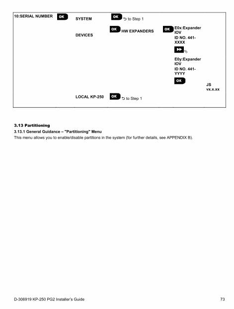
10:SERIAL NUMBER
SYSTEM to Step 1
DEVICES HW EXPANDERS
E0x:Expander IOV ID NO. 441-XXXX
E0y:Expander IOV ID NO. 441-YYYY
JS vx.x.xx
LOCAL KP-250 to Step 1
3.13 Partitioning 3.13.1 General Guidance – "Partitioning" Menu This menu allows you to enable/disable partitions in the system (for further details, see APPENDIX B).
D-306919 KP-250 PG2 Installer’s Guide 73
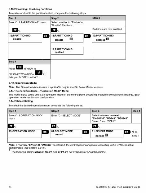
3.13.2 Enabling / Disabling Partitions To enable or disable the partition feature, complete the following steps:
Step 1 Step 2 Step 3
Select "12:PARTITIONING" menu Select whether to "Enable" or "Disable" Partitions
Partitions are now enabled
12:PARTITIONING disable
12:PARTITIONING disable
12:PARTITIONING
enabled
12:PARTITIONING enabled
Step 4
Press to return to
“12:PARTITIONING” or to take you to “<OK> to Exit”.
3.14 Operation Mode Note: The Operation Mode feature is applicable only in specific PowerMaster variants. 3.14.1 General Guidance – "Operation Mode" Menu This mode allows you to select an operation mode for the control panel according to specific compliance standards. Each operation mode has its own configuration. 3.14.2 Select Setting
To select the desired operation mode, complete the following steps:
Step 1 Step 2 Step 3 Step 4
Select "13:OPERATION MOD" menu
Enter "01:SELECT MODE" Select between “normal1”, "EN-50131", "DD243", "BS8243", “Incert1" and “CP011”
13:OPERATION MODE
01:SELECT MODE normal
01:SELECT MODE
normal to Step 1
Note: If "normal / EN-50131 / INCERT" is selected, the control panel will operate according to the OTHERS setup configuration (see section 3.14.6). 1 The following options normal, Incert, and CP01 are not available for all configurations.
74 D-306919 KP-250 PG2 Installer’s Guide
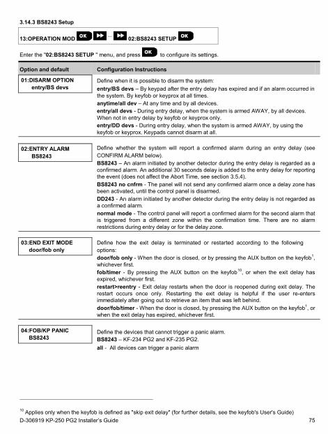
3.14.3 BS8243 Setup
13:OPERATION MOD ⋅⋅⋅ 02:BS8243 SETUP
Enter the "02:BS8243 SETUP " menu, and press to configure its settings.
Option and default Configuration Instructions
01:DISARM OPTION entry/BS devs
Define when it is possible to disarm the system: entry/BS devs – By keypad after the entry delay has expired and if an alarm occurred in the system. By keyfob or keyprox at all times. anytime/all dev – At any time and by all devices. entry/all devs - During entry delay, when the system is armed AWAY, by all devices. When not in entry delay by keyfob or keyprox only. entry/DD devs - During entry delay, when the system is armed AWAY, by using the keyfob or keyprox. Keypads cannot disarm at all.
02:ENTRY ALARM BS8243
Define whether the system will report a confirmed alarm during an entry delay (see CONFIRM ALARM below). BS8243 – An alarm initiated by another detector during the entry delay is regarded as a confirmed alarm. An additional 30 seconds delay is added to the entry delay for reporting the event (does not affect the Abort Time, see section 3.5.4). BS8243 no cnfrm - The panel will not send any confirmed alarm once a delay zone has been activated, until the control panel is disarmed. DD243 - An alarm initiated by another detector during the entry delay is not regarded as a confirmed alarm. normal mode - The control panel will report a confirmed alarm for the second alarm that is triggered from a different zone within the confirmation time. There are no alarm restrictions during entry delay or for the delay zone.
03:END EXIT MODE door/fob only
Define how the exit delay is terminated or restarted according to the following options: door/fob only - When the door is closed, or by pressing the AUX button on the keyfob1, whichever first. fob/timer - By pressing the AUX button on the keyfob10, or when the exit delay has expired, whichever first. restart>reentry - Exit delay restarts when the door is reopened during exit delay. The restart occurs once only. Restarting the exit delay is helpful if the user re-enters immediately after going out to retrieve an item that was left behind. door/fob/timer - When the door is closed, by pressing the AUX button on the keyfob1, or when the exit delay has expired, whichever first.
04:FOB/KP PANIC BS8243
Define the devices that cannot trigger a panic alarm. BS8243 – KF-234 PG2 and KF-235 PG2. all - All devices can trigger a panic alarm
10 Applies only when the keyfob is defined as "skip exit delay" (for further details, see the keyfob's User's Guide) D-306919 KP-250 PG2 Installer’s Guide 75
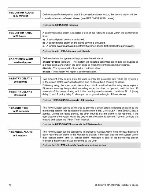
05:CONFIRM ALARM in 30 minutes Define a specific time period that if 2 successive alarms occur, the second alarm will be
considered as a confirmed alarm, (see RPT CNFM ALRM below).
Options: in 30/45/60/90 minutes
06:CONFIRM PANIC in 20 hours
A confirmed panic alarm is reported if one of the following occurs within the confirmation time: a) A second panic device is activated. b) A second panic alarm on the same device is activated. c) A tamper event is activated (not from the zone / device that initiated the panic alarm).
Options: in 4/8/12/20/24 hours and disable
07:RPT CNFM ALRM enable+bypass
Define whether the system will report a confirmed alarm. enable+bypass (default) - The system will report a confirmed alarm and will bypass all alarmed open zones when the siren ends or when the confirmation timer expires. disable - The system will not report a confirmed alarm. enable - The system will report a confirmed alarm.
08:ENTRY DELAY 1 30 seconds
Two different entry delays allow the user to enter the protected site (while the system is in the armed state) via 2 specific doors and routes without causing an alarm. Following entry, the user must disarm the control panel before the entry delay expires. Slow-rate warning beeps start sounding once the door is opened, until the last 10 seconds of the delay, during which the beeping rate increases. Locations No. 1 (entry delay 1) and 2 (entry delay 2) allow you to program the length of these delays.
09:ENTRY DELAY 2 60 second
Options: 10/15/30/45/60 seconds; 3/4 minutes
10:ABORT TIME in 30 seconds
The PowerMaster can be configured to provide a delay before reporting an alarm to the monitoring station (not applicable to alarms from FIRE, 24H SILENT and EMERGENCY zones). During this delay period, the siren sounds but the alarm is not reported. If the user disarms the system within the delay time, the alarm is aborted. You can activate the feature and select the "Abort Time" interval.
Options: in 00/15/30/45/60 seconds; in 2/3/4 minutes
11:CANCEL ALARM in 5 minutes
The PowerMaster can be configured to provide a “Cancel Alarm” time window that starts upon reporting an alarm to the Monitoring Station. If the user disarms the system within that "cancel alarm" time, a “cancel alarm” message is sent to the Monitoring Station indicating that the alarm was canceled by the user.
Options: in 1/5/15/60 minute/s; in 4 hours and not active
76 D-306919 KP-250 PG2 Installer’s Guide
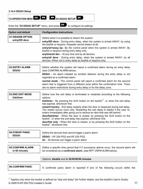
3.14.4 DD243 Setup
13:OPERATION MOD ⋅⋅⋅ 03:DD243 SETUP
Enter the "03:DD243 SETUP" menu, and press to configure its settings.
Option and default Configuration Instructions
01:DISARM OPTION entry/DD devs
Define when it is possible to disarm the system: entry/DD devs - During entry delay, when the system is armed AWAY, by using the keyfob or keyprox. Keypads cannot disarm at all. entry/wl+away kp– By the control panel when the system is armed AWAY. By keyfob or keyprox during entry delay only. anytime/all dev – At any time and by all devices. entry/all devs - During entry delay, when the system is armed AWAY, by all devices. When not in entry delay by keyfob or keyprox only.
02:ENTRY ALARM DD243
Define whether the system will report a confirmed alarm during an entry delay (see CONFIRM ALARM below). DD243 - An alarm initiated by another detector during the entry delay is not regarded as a confirmed alarm. normal mode - The control panel will report a confirmed alarm for the second alarm that is triggered from a different zone within the confirmation time. There are no alarm restrictions during entry delay or for the delay zone.
03:END EXIT MODE fob/timer
Define how the exit delay is terminated or restarted according to the following options: fob/timer - By pressing the AUX button on the keyfob11, or when the exit delay has expired, whichever first. restart>reentry - Exit delay restarts when the door is reopened during exit delay. The restart occurs once only. Restarting the exit delay is helpful if the user re-enters immediately after going out to retrieve an item that was left behind. door/fob/timer - When the door is closed, by pressing the AUX button on the keyfob1, or when the exit delay has expired, whichever first. door/fob only - When the door is closed, or by pressing the AUX button on the keyfob1, whichever first.
04:FOB/KP PANIC DD243
Define the devices that cannot trigger a panic alarm. DD243 – KF-234 PG2 and KF-235 PG2. all - All devices can trigger a panic alarm
05:CONFIRM ALARM in 60 minutes
Define a specific time period that if 2 successive alarms occur, the second alarm will be considered as a confirmed alarm, (see RPT CNFM ALRM below).
Options: disable and in 30/45/60/90 minutes
06:CONFIRM PANIC A confirmed panic alarm is reported if one of the following occurs within the
11 Applies only when the keyfob is defined as "skip exit delay" (for further details, see the keyfob's User's Guide) D-306919 KP-250 PG2 Installer’s Guide 77
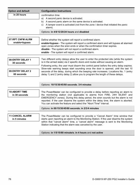
Option and default Configuration Instructions in 20 hours confirmation time:
a) A second panic device is activated. b) A second panic alarm on the same device is activated. c) A tamper event is activated (not from the zone / device that initiated the panic
alarm).
Options: in 4/8/12/20/24 hours and disabled
07:RPT CNFM ALRM enable+bypass
Define whether the system will report a confirmed alarm. enable+bypass - The system will report a confirmed alarm and will bypass all alarmed open zones when the siren ends or when the confirmation timer expires. disable - The system will not report a confirmed alarm. enable - The system will report a confirmed alarm.
08:ENTRY DELAY 1 30 seconds
Two different entry delays allow the user to enter the protected site (while the system is in the armed state) via 2 specific doors and routes without causing an alarm. Following entry, the user must disarm the control panel before the entry delay expires. Slow-rate warning beeps start sounding once the door is opened, until the last 10 seconds of the delay, during which the beeping rate increases. Locations No. 1 (entry delay 1) and 2 (entry delay 2) allow you to program the length of these delays.
09:ENTRY DELAY 2 60 seconds
Options: 10/15/30/45/60 seconds; 3/4 minutes
10:ABORT TIME
in 30 seconds The PowerMaster can be configured to provide a delay before reporting an alarm to the monitoring station (not applicable to alarms from FIRE, 24H SILENT and EMERGENCY zones). During this delay period, the siren sounds but the alarm is not reported. If the user disarms the system within the delay time, the alarm is aborted. You can activate the feature and select the "Abort Time" interval.
Options: in 00/15/30/45/60 seconds; in 2/3/4 minutes
11:CANCEL ALARM in 5 minutes
The PowerMaster can be configured to provide a “Cancel Alarm” time window that starts upon reporting an alarm to the Monitoring Station. If the user disarms the system within that "cancel alarm" time, a “cancel alarm” message is sent to the Monitoring Station indicating that the alarm was canceled by the user.
Options: in 1/5/15/60 minute/s; in 4 hours and not active
78 D-306919 KP-250 PG2 Installer’s Guide
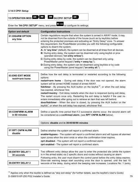
3.14.5 CP01 Setup
13:OPERATION MOD ⋅⋅⋅ 04:CP01 SETUP
Enter the "04:CP01 SETUP" menu, and press to configure its settings.
Option and default Configuration Instructions
01:DISARM OPTION any time
Certain regulations require that when the system is armed in AWAY mode, it may not be disarmed from the outside of the house (such as by keyfobs) before entering the protected premises and activating an "Entry Delay" zone. To answer this requirement, the PowerMaster provides you with the following configurable options to disarm the system: A: At "any time" (default), the system can be disarmed at all times from all devices. B: During entry delay, the system can be disarmed only using keyfob or prox
operated devices ("on entry wrless"). C: During entry delay by code, the system can be disarmed only using
PowerMaster panel keypad ("entry + away kp."). D: During entry delay, the system can be disarmed using keyfobs or by code
using the PowerMaster panel keypad ("on entry all.").
03:END EXIT MODE restrt+arm home
Define how the exit delay is terminated or restarted according to the following options: restart+arm home – During exit delay if the door was not opened, the alarm system will be armed HOME instead of armed AWAY. fob/timer - By pressing the AUX button on the keyfob12, or when the exit delay has expired, whichever first. restart>reentry - Exit delay restarts when the door is reopened during exit delay. The restart occurs once only. Restarting the exit delay is helpful if the user re-enters immediately after going out to retrieve an item that was left behind. door/fob/timer - When the door is closed, by pressing the AUX button on the keyfob1, or when the exit delay has expired, whichever first.
05:CONFIIRM ALARM in 60 minutes
Define a specific time period that if 2 successive alarms occur, the second alarm will be considered as a confirmed alarm, (see RPT CNFM ALRM below).
Options: disable and in 30/45/60/90 minutes
07:RPT CNFM ALRM disable
Define whether the system will report a confirmed alarm. enable+bypass - The system will report a confirmed alarm and will bypass all alarmed open zones when the siren ends or when the confirmation timer expires. rprt disabled - The system will not report a confirmed alarm. rprt enabled - The system will report a confirmed alarm.
08:ENTRY DELAY 1 30 seconds
Two different entry delays allow the user to enter the protected site (while the system is in the armed state) via 2 specific doors and routes without causing an alarm. Following entry, the user must disarm the control panel before the entry delay expires. Slow-rate warning beeps start sounding once the door is opened, until the last 10 seconds of the delay, during which the beeping rate increases. Locations No. 1 (entry
09:ENTRY DELAY 2
12 Applies only when the keyfob is defined as "skip exit delay" (for further details, see the keyfob's User's Guide) D-306919 KP-250 PG2 Installer’s Guide 79
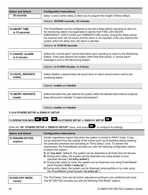
Option and default Configuration Instructions 30 seconds delay 1) and 2 (entry delay 2) allow you to program the length of these delays.
Options: 30/45/60 seconds; 3/4 minutes
10:ABORT TIME in 15 seconds
The PowerMaster can be configured to provide a delay before reporting an alarm to the monitoring station (not applicable to alarms from FIRE, 24H SILENT, EMERGENCY, GAS FLOOD and TEMPERATURE zones). During this delay period, the external siren will not sound and the alarm is not reported. If the user disarms the system within the delay time, the alarm is aborted.
Options: in 15/30/45 seconds
11:CANCEL ALARM in 5 minutes
Define the ”cancel alarm” period that starts upon reporting an alarm to the Monitoring Station. If the user disarms the system within that time period, a “cancel alarm” message is sent to the Monitoring Station.
Options: in 5/15/60 minutes; in 4 hours
12:CNCEL ANOUNCE enable
Define whether a special beep will sound when an alarm cancel event is sent to the monitoring station.
Options: enable and disable
13:ABORT ANOUNCE enable
Define that when the user disarms the system within the allowed abort interval a special beep will sound to indicate "no alarm transmission".
Options: enable and disable
3.14.6 OTHERS SETUP or EN50131 SETUP
13:OPERATION MOD ⋅⋅⋅ 05:OTHERS SETUP or EN50131 SETUP
Enter the "05: OTHERS SETUP or EN50131 SETUP" menu, and press to configure its settings.
Option and default Configuration Instructions
01:DISARM OPTION anytime
Certain regulations require that when the system is armed in AWAY mode, it may not be disarmed from the outside of the house (such as by keyfobs) before entering the protected premises and activating an "Entry Delay" zone. To answer this requirement, the PowerMaster provides you with the following configurable options to disarm the system: A: At "any time" (default), the system can be disarmed at all times from all devices. B: During entry delay, the system can be disarmed only using keyfob or prox
operated devices ("on entry wrless"). C: During entry delay by code, the system can be disarmed only using PowerMaster
panel keypad ("entry + away kp."). D: During entry delay, the system can be disarmed using keyfobs or by code using
the PowerMaster panel keypad ("on entry all.").
03:END EXIT MODE normal
The "Exit Delay" time can be further adjusted according to your preferred exit route. The KP-250 PG2 provides you with the following "Exit Mode" options:
80 D-306919 KP-250 PG2 Installer’s Guide
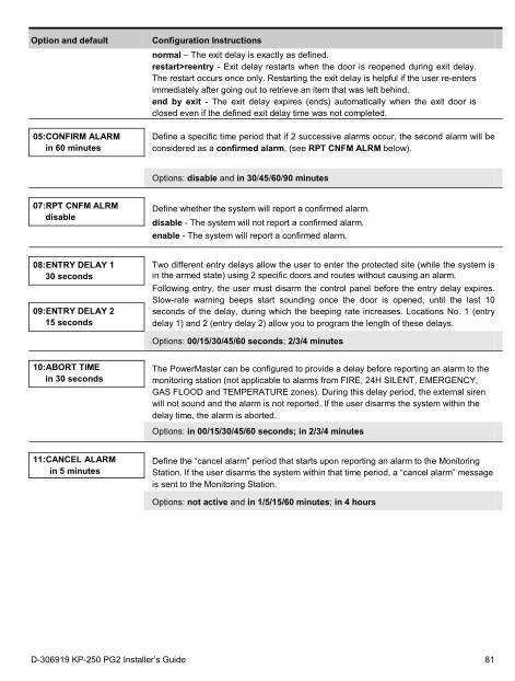
Option and default Configuration Instructions
normal – The exit delay is exactly as defined. restart>reentry - Exit delay restarts when the door is reopened during exit delay. The restart occurs once only. Restarting the exit delay is helpful if the user re-enters immediately after going out to retrieve an item that was left behind. end by exit - The exit delay expires (ends) automatically when the exit door is closed even if the defined exit delay time was not completed.
05:CONFIRM ALARM in 60 minutes
Define a specific time period that if 2 successive alarms occur, the second alarm will be considered as a confirmed alarm, (see RPT CNFM ALRM below).
Options: disable and in 30/45/60/90 minutes
07:RPT CNFM ALRM disable
Define whether the system will report a confirmed alarm. disable - The system will not report a confirmed alarm. enable - The system will report a confirmed alarm.
08:ENTRY DELAY 1 30 seconds
Two different entry delays allow the user to enter the protected site (while the system is in the armed state) using 2 specific doors and routes without causing an alarm. Following entry, the user must disarm the control panel before the entry delay expires. Slow-rate warning beeps start sounding once the door is opened, until the last 10 seconds of the delay, during which the beeping rate increases. Locations No. 1 (entry delay 1) and 2 (entry delay 2) allow you to program the length of these delays.
09:ENTRY DELAY 2
15 seconds
Options: 00/15/30/45/60 seconds; 2/3/4 minutes 10:ABORT TIME
in 30 seconds The PowerMaster can be configured to provide a delay before reporting an alarm to the monitoring station (not applicable to alarms from FIRE, 24H SILENT, EMERGENCY, GAS FLOOD and TEMPERATURE zones). During this delay period, the external siren will not sound and the alarm is not reported. If the user disarms the system within the delay time, the alarm is aborted.
Options: in 00/15/30/45/60 seconds; in 2/3/4 minutes
11:CANCEL ALARM
in 5 minutes Define the “cancel alarm” period that starts upon reporting an alarm to the Monitoring Station. If the user disarms the system within that time period, a “cancel alarm” message is sent to the Monitoring Station.
Options: not active and in 1/5/15/60 minutes; in 4 hours
D-306919 KP-250 PG2 Installer’s Guide 81
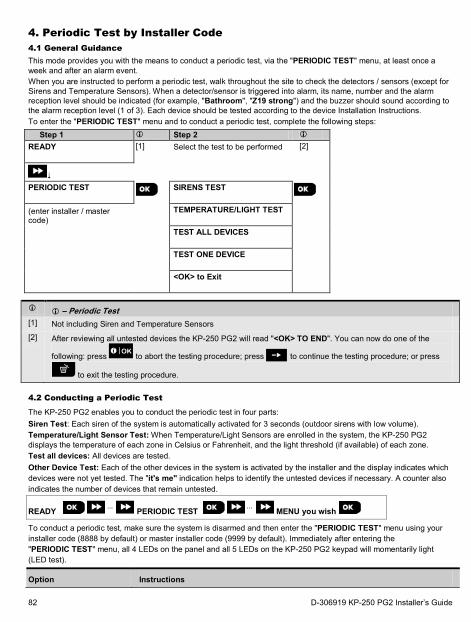
4. Periodic Test by Installer Code 4.1 General Guidance This mode provides you with the means to conduct a periodic test, via the "PERIODIC TEST" menu, at least once a week and after an alarm event. When you are instructed to perform a periodic test, walk throughout the site to check the detectors / sensors (except for Sirens and Temperature Sensors). When a detector/sensor is triggered into alarm, its name, number and the alarm reception level should be indicated (for example, "Bathroom", "Z19 strong") and the buzzer should sound according to the alarm reception level (1 of 3). Each device should be tested according to the device Installation Instructions. To enter the "PERIODIC TEST" menu and to conduct a periodic test, complete the following steps:
Step 1 Step 2
READY
[1] Select the test to be performed [2]
PERIODIC TEST
SIRENS TEST
(enter installer / master code)
TEMPERATURE/LIGHT TEST TEST ALL DEVICES TEST ONE DEVICE
<OK> to Exit
– Periodic Test
[1] Not including Siren and Temperature Sensors [2] After reviewing all untested devices the KP-250 PG2 will read "<OK> TO END". You can now do one of the
following: press to abort the testing procedure; press to continue the testing procedure; or press
to exit the testing procedure.
4.2 Conducting a Periodic Test
The KP-250 PG2 enables you to conduct the periodic test in four parts: Siren Test: Each siren of the system is automatically activated for 3 seconds (outdoor sirens with low volume). Temperature/Light Sensor Test: When Temperature/Light Sensors are enrolled in the system, the KP-250 PG2 displays the temperature of each zone in Celsius or Fahrenheit, and the light threshold (if available) of each zone. Test all devices: All devices are tested. Other Device Test: Each of the other devices in the system is activated by the installer and the display indicates which devices were not yet tested. The "it's me" indication helps to identify the untested devices if necessary. A counter also indicates the number of devices that remain untested.
READY ⋅⋅⋅ PERIODIC TEST ⋅⋅⋅ MENU you wish
To conduct a periodic test, make sure the system is disarmed and then enter the "PERIODIC TEST" menu using your installer code (8888 by default) or master installer code (9999 by default). Immediately after entering the "PERIODIC TEST" menu, all 4 LEDs on the panel and all 5 LEDs on the KP-250 PG2 keypad will momentarily light (LED test).
Option Instructions
82 D-306919 KP-250 PG2 Installer’s Guide
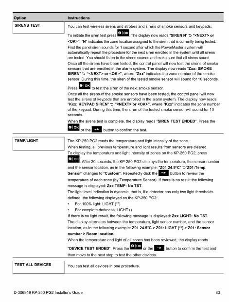
Option Instructions
SIRENS TEST
You can test wireless sirens and strobes and sirens of smoke sensors and keypads.
To initiate the siren test press . The display now reads "SIREN N" “<NEXT> or <OK>”. "N" indicates the zone location assigned to the siren that is currently being tested. First the panel siren sounds for 1 second after which the PowerMaster system will automatically repeat the procedure for the next siren enrolled in the system until all sirens are tested. You should listen to the sirens sounds and make sure that all sirens sound. Once all the sirens have been tested, the control panel will now test the sirens of smoke sensors that are enrolled in the alarm system. The display now reads "Zxx: SMOKE SIREN" “<NEXT> or <OK>”, where "Zxx" indicates the zone number of the smoke sensor. During this time, the siren of the tested smoke sensor will sound for 10 seconds.
Press to test the siren of the next smoke sensor. Once all the sirens of the smoke sensors have been tested, the control panel will now test the sirens of keypads that are enrolled in the alarm system. The display now reads "Kxx: KEYPAD SIREN" “<NEXT> or <OK>”, where "Kxx" indicates the zone number of the keypad. During this time, the siren of the tested smoke sensor will sound for 10 seconds.
When the sirens test is complete, the display reads "SIREN TEST ENDED". Press the
or the button to confirm the test.
TEMP/LIGHT
The KP-250 PG2 reads the temperature and light intensity of the zone. When testing, all previous temperature and light results from sensors are cleared. To display the temperature and light intensity of zones on the KP-250 PG2, press
. After 20 seconds, the KP-250 PG2 displays the temperature, the sensor number and the sensor location, as in the following example: "Z01 24.5°C" "Z01:Temp. Sensor" changes to "Custom". Repeatedly click the button to review the
temperature of each zone (by Temperature Sensor). If there is no result the following message is displayed: Zxx TEMP: No TST. The light level indication is dynamic, that is, if a detector has only two light thresholds defined, the following displayed on the KP-250 PG2: • For 100% light: LIGHT (**) • For complete darkness: LIGHT () If there is no light result, the following message is displayed: Zxx LIGHT: No TST. The display alternates between the temperature, light sensor number, and the sensor location, as in the following example: Z01 24.5°C > Z01: LIGHT (**) > Z01: Sensor number > Room location. When the temperature and light of all zones has been reviewed, the display reads
"DEVICE TEST ENDED". Press the or the button to confirm the test and
then move to the next step to test the other devices.
TEST ALL DEVICES
You can test all devices in one procedure.
D-306919 KP-250 PG2 Installer’s Guide 83
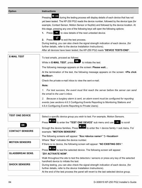
Option Instructions
Pressing during the testing process will display details of each device that has not yet been tested. The KP-250 PG2 reads the device number, followed by the device type (for example, Contact Sensor, Motion Sensor or Keyfob) and followed by the device location. At this stage, pressing any one of the following keys will open the following options:
1. Press to view details of the next untested device.
2. Press to exit the test process. During testing, you can also check the signal strength indication of each device, (for further details, refer to the device Installation Instructions). After all devices have been tested, the KP-250 PG2 reads "DEVICE TESTS END".
E-MAIL TEST To test emails, proceed as follows:
While in E-MAIL TEST, press to initiate the test.
The following message appears on the screen: Please wait…
At the termination of the test, the following message appears on the screen: <Pls chck MailBox>.
Check the private e-mail inbox to view the sent e-mail.
Note:
1. For test success, the event must first reach the server before the server can send the email to the user’s inbox.
2. Because a burglary alarm is sent, an alarm event must be configured for reporting events (see sections 4.6.3 Configuring Events Reporting to Monitoring Stations and 4.6.4 Configuring Events Reporting to Private Users).
TEST ONE DEVICE
Select a specific device group you wish to test. For example, Motion Sensors.
Press to enter the "TEST ONE DEVICE" sub menu and use to scroll
through the device families. Press to enter the < device family > sub menu. For example: "MOTION SENSORS".
The following screens will appear: "Xxx:<device name>" <location> Where "Xxx" indicates the device number. If there is no device, the following screen will appear: "NO EXISTING DEV.".
Press to test the selected device. The following screen will appear: "Z01 ACTIVATE NOW".
Walk throughout the site to test the detectors / sensors or press any key of the selected handheld device to initiate the test. During testing, you can also check the signal strength indication of each device, (for further details, refer to the device Installation Instructions). At the end of the test process the panel will revert to the last selected device group.
CONTACT SENSORS
MOTION SENSORS
GLASSBREAK SENS.
SHOCK SENSORS
84 D-306919 KP-250 PG2 Installer’s Guide
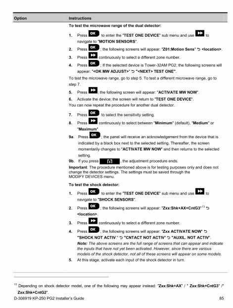
Option Instructions
To test the microwave range of the dual detector:
1. Press to enter the "TEST ONE DEVICE" sub menu and use to navigate to "MOTION SENSORS".
2. Press ; the following screens will appear: "Z01:Motion Sens" <location>.
3. Press continuously to select a different zone number.
4. Press ; If the selected device is Tower-32AM PG2, the following screens will appear: "<OK MW ADJUST>" "<NEXT> TEST ONE".
To test the microwave range, go to step 5. To test a different microwave range, go to step 7.
5. Press ; the following screen will appear: "ACTIVATE MW NOW".
6. Activate the device; the screen will return to "TEST ONE DEVICE". You can now repeat the procedure for another dual detector.
7. Press to select the sensitivity setting.
8. Press continuously to select between "Minimum" (default), "Medium" or "Maximum"
9a. Press ; the panel will receive an acknowledgement from the device that is indicated by a black box next to the selected setting. Thereafter, the screen momentarily changes to "ACTIVATE MW NOW" and then returns to the selected setting.
9b. If you press , the adjustment procedure ends. Important: The procedure mentioned above is for testing purposes only and does not change the detector settings. The settings must be saved through the MODIFY DEVICES menu.
To test the shock detector:
1. Press to enter the "TEST ONE DEVICE" sub menu and use to navigate to "SHOCK SENSORS".
2. Press ; the following screens will appear: "Zxx:Shk+AX+CntG3"13 <location>.
3. Press continuously to select a different zone number.
4. Press ; the following screens will appear: "Zxx ACTIVATE NOW" "SHOCK NOT ACTIV." "CNTACT NOT ACTIV" "AUXIL. NOT ACTIV". Note: The above screens are the full range of screens that can appear and indicate the inputs that have not yet been activated. However, since there are various models of the shock detector, not all of these screens will appear on some models.
5. At this stage, activate each input of the shock detector in turn.
13 Depending on shock detector model, one of the following may appear instead: "Zxx:Shk+AX" / " Zxx:Shk+CntG3" /" Zxx:Shk+CntG2".
D-306919 KP-250 PG2 Installer’s Guide 85
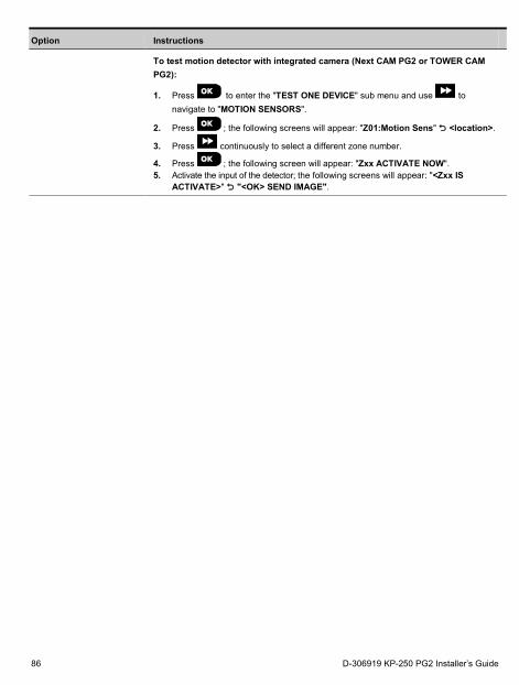
Option Instructions
To test motion detector with integrated camera (Next CAM PG2 or TOWER CAM PG2):
1. Press to enter the "TEST ONE DEVICE" sub menu and use to navigate to "MOTION SENSORS".
2. Press ; the following screens will appear: "Z01:Motion Sens" <location>.
3. Press continuously to select a different zone number.
4. Press ; the following screen will appear: "Zxx ACTIVATE NOW". 5. Activate the input of the detector; the following screens will appear: "<Zxx IS
ACTIVATE>" "<OK> SEND IMAGE".
86 D-306919 KP-250 PG2 Installer’s Guide

5. Handling System Troubles Fault What it means Solution
1-WAY
The control panel cannot configure or control the device. Battery consumption increases.
1. Make sure the device is physically present.
2. Check the display for device faults, for example, low battery.
3. Use RF diagnostics to check the current signal strength and during the last 24 hours.
4. Open the device cover and replace the battery or press the tamper switch.
5. Install the device in a different location.
6. Replace the device.
AC FAILURE
There is no power to gas sensor Make sure that the AC power supply is connected properly
AC SUPPLY FAILURE
There is no power and the system is working on backup battery power
Make sure that the AC power supply is connected properly
FIRE CLEAN
The fire detector must be cleaned Use a vacuum cleaner to clean the detector air vents occasionally to keep them free of dust.
COMM. FAILURE
A message could not be sent to the monitoring station or to a private telephone (or a message was sent but was not acknowledged)
1. Check telephone cable connection 2. Check that correct telephone
number has been dialed. 3. Dial Monitoring Station to check
whether or not events are received.
CPU LOW BATTERY
The backup battery within the control panel is weak and must be replaced (refer to the PowerMaster-10/30 G2 Installer’s Guide, section 7.3, or, PowerMaster-33 G2 Installer’s Guide, section 5.2).
1. Check for AC power is available in the Panel.
2. If trouble exists for more than 72 hours, replace the battery pack
CPU TAMPER OPEN
The control panel was physically tampered with or its cover was opened, or it was removed from wall.
The control panel is not closed properly. Open the control panel and then close it.
FUSE FAILURE
The PGM fuse is burnt out or overloaded.
Make sure that the connection load conforms to that specified in the Specifications.
GAS TROUBLE
Gas detector failure Gas detector: Disconnect and then put back the AC power supply connector. CO Gas detector: Replace the detector.
GSM NET FAIL
The GSM communicator is not able to connect to the cellular network.
1. Move the Panel and GSM unit to another location.
D-306919 KP-250 PG2 Installer’s Guide 87
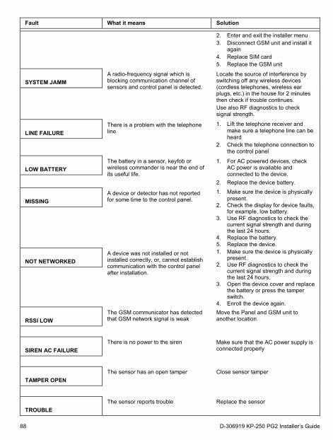
Fault What it means Solution
2. Enter and exit the installer menu 3. Disconnect GSM unit and install it
again 4. Replace SIM card 5. Replace the GSM unit
SYSTEM JAMM
A radio-frequency signal which is blocking communication channel of sensors and control panel is detected.
Locate the source of interference by switching off any wireless devices (cordless telephones, wireless ear plugs, etc.) in the house for 2 minutes then check if trouble continues. Use also RF diagnostics to check signal strength.
LINE FAILURE
There is a problem with the telephone line
1. Lift the telephone receiver and make sure a telephone line can be heard
2. Check the telephone connection to the control panel
LOW BATTERY
The battery in a sensor, keyfob or wireless commander is near the end of its useful life.
1. For AC powered devices, check AC power is available and connected to the device.
2. Replace the device battery.
MISSING
A device or detector has not reported for some time to the control panel.
1. Make sure the device is physically present.
2. Check the display for device faults, for example, low battery.
3. Use RF diagnostics to check the current signal strength and during the last 24 hours.
4. Replace the battery. 5. Replace the device.
NOT NETWORKED
A device was not installed or not installed correctly, or, cannot establish communication with the control panel after installation.
1. Make sure the device is physically present.
2. Use RF diagnostics to check the current signal strength and during the last 24 hours.
3. Open the device cover and replace the battery or press the tamper switch.
4. Enroll the device again.
RSSI LOW
The GSM communicator has detected that GSM network signal is weak
Move the Panel and GSM unit to another location.
SIREN AC FAILURE
There is no power to the siren Make sure that the AC power supply is connected properly
TAMPER OPEN
The sensor has an open tamper Close sensor tamper
TROUBLE
The sensor reports trouble Replace the sensor
88 D-306919 KP-250 PG2 Installer’s Guide
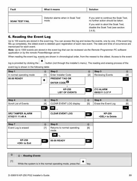
Fault What it means Solution
SOAK TEST FAIL
Detector alarms when in Soak Test mode
If you wish to continue the Soak Test, no further action should be taken. If you wish to abort the Soak Test, disable the Soak Test (see section 3.4.6).
6. Reading the Event Log Up to 100 events are stored in the event log. You can access this log and review the events, one by one. If the event log fills up completely, the oldest event is deleted upon registration of each new event. The date and time of occurrence are memorized for each event. Note: Up to 1000 events are stored in the event log that can be reviewed via the Remote Programmer PC software application or by the remote PowerManage server.
When reading the event log, events are shown in chronological order, from the newest to the oldest. Access to the event
log is provided by clicking the button (not through the installer’s menu). The reading and erasing process of the
event log is shown in the following table:
Step 1 Step 2 Step 3
In normal operating mode [1] Enter Installer Code [2] Reviewing Events [3] 00:00 READY
PRESENT TAG OR
ENTER CODE
KP-250
LIST OF EVENTS Z13 ALARM 09/02/11 3:37 P
Step 4 Step 5 Step 6
Scroll List of Events [4] CLEAR EVENT LOG display [5] Erase the Event Log [6]
➯
SR2 TAMPER ALARM 07/02/11 11:49 A
CLEAR EVENT LOG
KP-250 <DEL> to Delete
Step 7 Step 8
Event Log is erased [7] Returns to normal operating mode
[8]
KP-250 <OK> to Exit
00:00 READY
- Reading Events
[1] While the system is in the normal operating mode, press the key.
D-306919 KP-250 PG2 Installer’s Guide 89
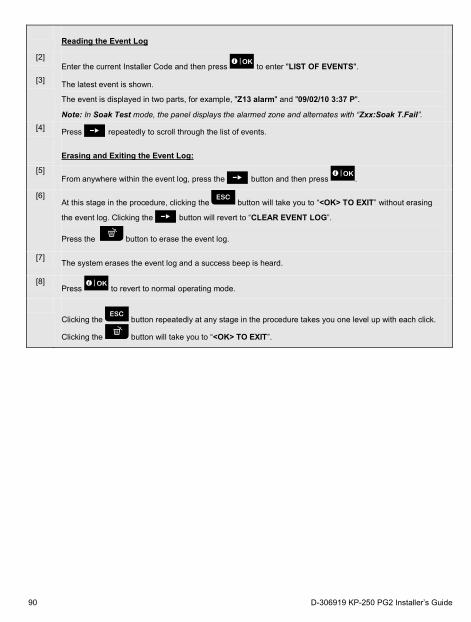
Reading the Event Log
[2] Enter the current Installer Code and then press to enter "LIST OF EVENTS".
[3] The latest event is shown.
The event is displayed in two parts, for example, "Z13 alarm" and "09/02/10 3:37 P".
Note: In Soak Test mode, the panel displays the alarmed zone and alternates with “Zxx:Soak T.Fail”. [4] Press repeatedly to scroll through the list of events.
Erasing and Exiting the Event Log:
[5] From anywhere within the event log, press the button and then press .
[6] At this stage in the procedure, clicking the button will take you to “<OK> TO EXIT” without erasing
the event log. Clicking the button will revert to “CLEAR EVENT LOG”.
Press the button to erase the event log.
[7] The system erases the event log and a success beep is heard.
[8] Press to revert to normal operating mode.
Clicking the button repeatedly at any stage in the procedure takes you one level up with each click.
Clicking the button will take you to “<OK> TO EXIT”.
90 D-306919 KP-250 PG2 Installer’s Guide

APPENDIX A: Specifications Frequency Band (MHz) Europe and rest of world: 433-434, 868-869 USA: 912-919 Communication Protocol PowerG Battery type Four 1.5V AA Alkaline batteries Battery Life Expectancy 3 years (for typical use). Low Battery Threshold 4.4 V Power source Battery: 4.8VDC – 6VDC
Back light Blue (keypad) / white (display) Operating Temperature 0°C to 55°C (32°F to 131°F) Humidity Average relative humidity of approx. 75% non-condensing. For 30 days per year,
relative humidity may vary from 85% to 95% non-condensing. Dimensions (WxLxD) 150x100x20mm (5-7/8 x 3-7/8 x 13/16 in) Weight (including battery and bracket) 379 g (13 oz). Mounting Wall-mounted or desktop Color White
D-306919 KP-250 PG2 Installer’s Guide 91
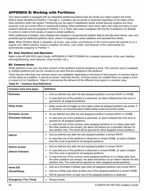
APPENDIX B: Working with Partitions Your alarm system is equipped with an integrated partitioning feature that can divide your alarm system into three distinct areas identified as Partition 1 through 3. A partition can be armed or disarmed regardless of the status of the other partitions within the system. Partitioning can be used in installations where shared security systems are more practical, such as a home office or warehouse building. When partitioned, each zone, each user code and many of your system's features can be assigned to Partition 1 to 3. Each user code is assigned with the list of partitions it is allowed to control in order to limit access of users to certain partitions. When partitioning is enabled, menu displays are changed to incorporate the partition feature and also each device, user, and proximity tag has additional partitions menu, where it is assigned to certain partitions and excluded from others. Note: When Partition Mode is disabled, all zones, user codes, and features of the control panel will operate as in a regular unit. When partition mode is enabled, all zones, user codes, and features of the control panel are automatically assigned to Partition 1.
B1. User Interface and Operation Refer to the KP-250 PG2 User's Guide, APPENDIX B. PARTITIONING for a detailed description of the user interface (Arming/Disarming, siren behavior, show function, etc.).
B2. Common Areas When partitions cross over, the area common to the partitions must be assigned a zone. This common zone is assigned to multiple partitions and can be crossed by all users that are assigned to the partitions. There may be more than one common area in an installation depending on the layout of the property. A common area is not the same as a partition; it cannot be armed / disarmed directly. Common areas are created when you assign a zone or zones to 2 or 3 partitions. Table A1 summarizes the behavior of the different zone types in a common area. Table A1 – Common Area Definitions
Common area zone types Definition
Perimeter • Acts as defined only after the last assigned partition is armed AWAY or HOME. • In case that one of the partitions is disarmed, an alarm initiated from this zone is
ignored for all assigned partitions.
Delay zones • Delay zones will not trigger an entry delay unless all assigned partitions are armed. It is, therefore, not recommended to define delay zones as common areas.
Perimeter access (Perimeter follower)
• Act as defined only after the last assigned partition is armed AWAY or HOME. • In case that one of the partitions is disarmed, an alarm initiated from this zone is
ignored for all assigned partitions. • In case that one of the common area assigned partitions is in a delay state (and
the other partitions are armed), the alarm will behave as a perimeter follower for this partition only. The event will be ignored for other assigned armed partitions.
Interior • Acts as defined only after the last assigned partition is armed AWAY. • In case that one of the partitions is disarmed or armed HOME, an alarm initiated
from this zone is ignored for all assigned partitions.
Interior access
(Interior follower)
• Acts as defined only after the last assigned partition is armed AWAY. • In case that one of the partitions is disarmed or armed HOME, an alarm initiated
from this zone is ignored for all assigned partitions. • In case that one of the common area assigned partitions is in a delay state (and
the other partitions are armed), the alarm will behave as an interior follower for this partition only. The event will be ignored for other assigned armed partitions.
Home E/E (Home/Delay)
• Acts as a Perimeter-Follower type when all assigned partitions are armed AWAY. • Acts as a Delay type when at least one of the assigned partitions is armed HOME. • Will be ignored when at least one of the assigned partitions is disarmed.
Emergency; Fire; Flood; • Always armed.
92 D-306919 KP-250 PG2 Installer’s Guide
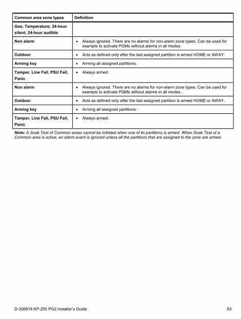
Common area zone types Definition
Gas; Temperature; 24-hour silent; 24-hour audible
Non alarm • Always ignored. There are no alarms for non-alarm zone types. Can be used for example to activate PGMs without alarms in all modes.
Outdoor • Acts as defined only after the last assigned partition is armed HOME or AWAY.
Arming key • Arming all assigned partitions.
Tamper, Line Fail, PSU Fail, Panic
• Always armed.
Note: A Soak Test of Common areas cannot be initiated when one of its partitions is armed. When Soak Test of a Common area is active, an alarm event is ignored unless all the partitions that are assigned to the zone are armed.
D-306919 KP-250 PG2 Installer’s Guide 93

APPENDIX C: Glossary
Abort Period: When an alarm is initiated, the internal sounder is activated first for a limited period of time which is the abort period set by the installer. If you cause an alarm accidentally, you can disarm the system within the abort period before the real sirens start and before the alarm is reported to the remote responders. Alarm: There are 2 kinds of alarms: Loud alarm - both internal sounder and external siren blare out constantly and the control panel reports the event by telephone. Silent alarm - the sirens remain silent, but the control panel reports the event by telephone. A state of alarm is caused by: • Motion detected by a motion detector • Change of state detected by a magnetic contact detector - a closed window or door is opened • Detection of smoke by a smoke detector • Tampering with any one of the detectors • Pressing the two emergency buttons simultaneously (panic). Arming: Arming the alarm system is an action that prepares it to sound an alarm if a zone is “violated” by motion or by opening a door or window, as the case may be. The control panel may be armed in various modes (see AWAY, HOME, INSTANT and LATCHKEY). Assigned: Refers to zones. Associated: Refers to devices. AWAY: This type of arming is used when the protected site is vacated entirely. All zones, interior and perimeter alike, are protected. Chime Zones: Allow you to keep track of activity in the protected area while the alarm system is in the disarmed state. Whenever a chime zone is "opened", the buzzer beeps twice. The buzzer does not beep, however, upon closing the zone (return to normal). Residences can use this feature to annunciate visitors or look after children. Businesses can use it to signal when customers enter the premises or when personnel enter restricted areas. Note: Your installer will never designate a 24-hour zone or a fire zone as a chime zone, because both zone types actuate an alarm if disturbed while the system is in the disarmed state. Although one zone or more are designated as chime zones, you can still enable or disable the chime function. Communicators: Refers to communication channel, for example, GSM. Control Panel: The control panel is a cabinet that incorporates the electronic circuitry and microprocessor that control the alarm system. It collects information from various sensors, processes it and responds in various ways. It also includes the user-interface - control keys, numerical keypad, display, sounder and loudspeaker. Default Settings: Settings that are applicable to a specific device group. Detector: The device (apparatus) that sends an alarm, that communicates with the control panel (for example, Next PG2 is a motion detector; SMD-426 PG2 is a smoke detector). Disarming: The opposite of arming - an action that restores the control panel to the normal standby state. In this state, only fire and 24-hour zones will sound an alarm if violated, but a “panic alarm” may also be initiated. Disturbed Zone: A zone in a state of alarm (this may be caused by an open window or door or by motion in the field of view of a motion detector). A disturbed zone is considered “not secured”. Forced Arming: When any one of the system zones is disturbed (open), the alarm system cannot be armed. One way to solve this problem is to find and eliminate the cause for zone disturbance (closing doors and windows). Another way to deal with this is to impose forced arming - automatic de-activation of zones that are still disturbed upon termination of the exit delay. Bypassed zones will not be protected throughout the arming period. Even if restored to normal (closed), bypassed zones will remain unprotected until the system is disarmed. Permission to “force arm” is given or denied by the installer while programming the system.
94 D-306919 KP-250 PG2 Installer’s Guide

HOME: This type of arming is used when people are present within the protected site. A classic example is night-time at home, when the family is about to retire to bed. With HOME arming, perimeter zones are protected but interior zones are not. Consequently, motion within interior zones will be ignored by the control panel, but disturbance of a perimeter zone will cause an alarm. Instant: You can arm the system AWAY-INSTANT or HOME-INSTANT, thereby canceling the entry delay for all delay zones for the duration of one arming period. For example, you may arm the control panel in the HOME-INSTANT mode and remain within the protected area. Only perimeter protection is active, and if you do not expect somebody to drop in while the system is armed, alarm upon entry via the main door is an advantage. To disarm the system without causing an alarm, use your control keypad (which is normally accessible without disturbing a perimeter zone) or use a keyfob transmitter. Latchkey: The Latchkey mode is a special arming mode in which designated "latchkey users" will trigger a "latchkey message" to be sent to a telephone when they disarm the system. For example, if a parent wants to be sure that their child has returned from school and disarmed the system. Latchkey arming is only possible when the system is armed in the AWAY mode. Location: Assigning a named location to a device (for example, Garage, Front Door etc.) Magnetic Contact Detector, Wireless: A Magnet- controlled switch and a wireless PowerG transmitter in a shared housing. The detector is mounted on doors and windows to detect changes in state (from closed to open and vice versa). Upon sensing that a door or window is open, the detector transmits its unique identification code accompanied by an “alarm” signal and various other status signals to the control panel. The control panel, if not armed at that time, will consider the alarm system as “not ready for arming” until it receives a “restored” signal from the same detector. Motion Detector, Wireless: A passive Infrared motion sensor and a wireless PowerG transmitter in a shared housing. Upon sensing motion, the detector transmits its unique identification code, accompanied by an alarm signal and various other status signals to the control panel. After transmission, it stands by to sense further motion. Non-Alarm Zone: Your installer can designate a zone for roles other than alarm. For instance, a motion detector installed in a dark stairway may be used to switch on lights automatically when someone crosses the dark area. Another example is a wireless transmitter linked to a zone that controls a gate opening mechanism. Quick Arming: Arming without a user code. The control panel does not request your user code when you press one of the arming buttons. Permission to use this arming method is given or denied by the installer while programming the system. Remote Responder: A responder can be either a professional service provider to which the home or business owner subscribes (a Monitoring Station) or a family relation/friend who agrees to look after the protected site during absence of its occupants. The control panel reports events by telephone to both kinds of responders. Restore: When a detector reverts from the state of alarm to the normal standby state, it is said to have been “restored”. A motion detector restores automatically after detection of movement, and becomes ready to detect again. This kind of “restore” is not reported to the remote responders. A magnetic contact detector restores only upon closure of the protected door or window. This kind of “restore” is reported to the remote responders. Sensor: The sensing element: pyroelectric sensor, photo-diode, microphone, smoke optical sensor etc. Signal Strength: The quality link communication between the system components and the control panel. Smoke Detector, Wireless: A regular smoke detector and a wireless PowerG transmitter in a shared housing. Upon detection of smoke, the detector transmits its unique identification code accompanied by an alarm signal and various status signals to the control panel. Since the smoke detector is linked to a special fire zone, a fire alarm is initiated. State: AWAY, HOME, AWAY-INSTANT, HOME-INSTANT, LATCHKEY, FORCED, BYPASS. Status: AC fail, low battery, trouble, etc. User Codes: The KP-250 PG2 is designed to obey your commands, provided that they are preceded by a valid security access code. Unauthorized people do not know this code, so any attempt on their part to disarm or defeat the system is bound to fail. Some operations, however, can be carried out without a user code as they do not degrade the security level of the alarm system.
D-306919 KP-250 PG2 Installer’s Guide 95

Zone: A zone is an area within the protected site under supervision of a specific detector. During programming, the installer allows the control panel to learn the detector’s identity code and links it to the desired zone. Since the zone is distinguished by number and name, the control panel can report the zone status to the user and register in its memory all the events reported by the zone detector. Instant and delay zones are “on watch” only when the control panel is armed, and other (24-hour) zones are “on watch” regardless of whether the system is armed or not.
Zone Type: The zone type determines how the system handles alarms and other signals sent from the device.
96 D-306919 KP-250 PG2 Installer’s Guide
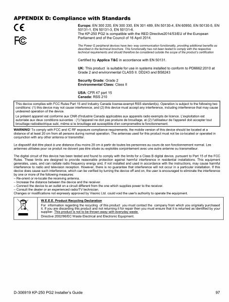
APPENDIX D: Compliance with Standards
Europe: EN 300 220, EN 300 330, EN 301 489, EN 50130-4, EN 60950, EN 50130-5, EN 50131-1, EN 50131-3, EN 50131-6. The KP-250 PG2 is compatible with the RED Directive2014/53/EU of the European Parliament and of the Council of 16 April 2014. The Power G peripheral devices have two- way communication functionality, providing additional benefits as described in the technical brochure. This functionality has not been tested to comply with the respective technical requirements and should therefore be considered outside the scope of the product’s certification Certified by Applica T&C in accordance with EN 50131. UK: This product is suitable for use in systems installed to conform to PD6662:2010 at Grade 2 and environmental CLASS II. DD243 and BS8243 Security Grade: Grade 2 Environmental Class: Class II USA: CFR 47 part 15 Canada: RSS 210
This device complies with FCC Rules Part 15 and Industry Canada license-exempt RSS standard(s). Operation is subject to the following two conditions: (1) this device may not cause interference, and (2) this device must accept any interference, including interference that may cause undesired operation of the device. Le présent appareil est conforme aux CNR d'Industrie Canada applicables aux appareils radio exempts de licence. L'exploitation est autorisée aux deux conditions suivantes : (1) l'appareil ne doit pas produire de brouillage, et (2) l'utilisateur de l'appareil doit accepter tout brouillage radioélectrique subi, même si le brouillage est susceptible d'en compromettre le fonctionnement.
WARNING! To comply with FCC and IC RF exposure compliance requirements, the mobile version of this device should be located at a distance of at least 20 cm from all persons during normal operation. The antennas used for this product must not be co-located or operated in conjunction with any other antenna or transmitter.
Le dispositif doit être placé à une distance d'au moins 20 cm à partir de toutes les personnes au cours de son fonctionnement normal. Les antennes utilisées pour ce produit ne doivent pas être situés ou exploités conjointement avec une autre antenne ou transmetteur. The digital circuit of this device has been tested and found to comply with the limits for a Class B digital device, pursuant to Part 15 of the FCC Rules. These limits are designed to provide reasonable protection against harmful interference in residential installations. This equipment generates, uses, and can radiate radio frequency energy and, if not installed and used in accordance with the instructions, may cause harmful interference to radio and television reception. However, there is no guarantee that interference will not occur in a particular installation. If this device does cause such interference, which can be verified by turning the device off and on, the user is encouraged to eliminate the interference by one or more of the following measures: – Re-orient or re-locate the receiving antenna. – Increase the distance between the device and the receiver. – Connect the device to an outlet on a circuit different from the one which supplies power to the receiver. – Consult the dealer or an experienced radio/TV technician. Changes or modifications not expressly approved by Visonic Ltd. could void the user's authority to operate the equipment.
W.E.E.E. Product Recycling Declaration For information regarding the recycling of this product you must contact the company from which you orignially purchased it. If you are discarding this product and not returning it for repair then you must ensure that it is returned as identified by your supplier. This product is not to be thrown away with everyday waste. Directive 2002/96/EC Waste Electrical and Electronic Equipment.
D-306919 KP-250 PG2 Installer’s Guide 97
WARRANTY Visonic Limited (the “Manufacturer") warrants this product only (the "Product") to the original purchaser only (the “Purchaser”) against defective workmanship and materials under normal use of the Product for a period of twelve (12) months from the date of shipment by the Manufacturer. This Warranty is absolutely conditional upon the Product having been properly installed, maintained and operated under conditions of normal use in accordance with the Manufacturers recommended installation and operation instructions. Products which have become defective for any other reason, according to the Manufacturers discretion, such as improper installation, failure to follow recommended installation and operational instructions, neglect, willful damage, misuse or vandalism, accidental damage, alteration or tampering, or repair by anyone other than the manufacturer, are not covered by this Warranty. The Manufacturer does not represent that this Product may not be compromised and/or circumvented or that the Product will prevent any death and/or personal injury and/or damage to property resulting from burglary, robbery, fire or otherwise, or that the Product will in all cases provide adequate warning or protection. The Product, properly installed and maintained, only reduces the risk of such events without warning and it is not a guarantee or insurance that such events will not occur. THIS WARRANTY IS EXCLUSIVE AND EXPRESSLY IN LIEU OF ALL OTHER WARRANTIES, OBLIGATIONS OR LIABILITIES, WHETHER WRITTEN, ORAL, EXPRESS OR IMPLIED, INCLUDING ANY WARRANTY OF MERCHANTABILITY OR FITNESS FOR A PARTICULAR PURPOSE, OR OTHERWISE. IN NO CASE SHALL THE MANUFACTURER BE LIABLE TO ANYONE FOR ANY CONSEQUENTIAL OR INCIDENTAL DAMAGES FOR BREACH OF THIS WARRANTY OR ANY OTHER WARRANTIES WHATSOEVER, AS AFORESAID.
THE MANUFACTURER SHALL IN NO EVENT BE LIABLE FOR ANY SPECIAL, INDIRECT, INCIDENTAL, CONSEQUENTIAL OR PUNITIVE DAMAGES OR FOR LOSS, DAMAGE, OR EXPENSE, INCLUDING LOSS OF USE, PROFITS, REVENUE, OR GOODWILL, DIRECTLY OR INDIRECTLY ARISING FROM PURCHASER’S USE OR INABILITY TO USE THE PRODUCT, OR FOR LOSS OR DESTRUCTION OF OTHER PROPERTY OR FROM ANY OTHER CAUSE, EVEN IF MANUFACTURER HAS BEEN ADVISED OF THE POSSIBILITY OF SUCH DAMAGE. THE MANUFACTURER SHALL HAVE NO LIABILITY FOR ANY DEATH, PERSONAL AND/OR BODILY INJURY AND/OR DAMAGE TO PROPERTY OR OTHER LOSS WHETHER DIRECT, INDIRECT, INCIDENTAL, CONSEQUENTIAL OR OTHERWISE, BASED ON A CLAIM THAT THE PRODUCT FAILED TO FUNCTION. However, if the Manufacturer is held liable, whether directly or indirectly, for any loss or damage arising under this limited warranty, THE MANUFACTURER'S MAXIMUM LIABILITY (IF ANY) SHALL NOT IN ANY CASE EXCEED THE PURCHASE PRICE OF THE PRODUCT, which shall be fixed as liquidated damages and not as a penalty, and shall be the complete and exclusive remedy against the Manufacturer. When accepting the delivery of the Product, the Purchaser agrees to the said conditions of sale and warranty and he recognizes having been informed of. Some jurisdictions do not allow the exclusion or limitation of incidental or consequential damages, so these limitations may not apply under certain circumstances. The Manufacturer shall be under no liability whatsoever arising out of the corruption and/or malfunctioning of any telecommunication or electronic equipment or any programs.
The Manufacturers obligations under this Warranty are limited solely to repair and/or replace at the Manufacturer’s discretion any Product or part thereof that may prove defective. Any repair and/or replacement shall not extend the original Warranty period. The Manufacturer shall not be responsible for dismantling and/or reinstallation costs. To exercise this Warranty the Product must be returned to the Manufacturer freight pre-paid and insured. All freight and insurance costs are the responsibility of the Purchaser and are not included in this Warranty. This warranty shall not be modified, varied or extended, and the Manufacturer does not authorize any person to act on its behalf in the modification, variation or extension of this warranty. This warranty shall apply to the Product only. All products, accessories or attachments of others used in conjunction with the Product, including batteries, shall be covered solely by their own warranty, if any.
The Manufacturer shall not be liable for any damage or loss whatsoever, whether directly, indirectly, incidentally, consequentially or otherwise, caused by the malfunction of the Product due to products, accessories, or attachments of others, including batteries, used in conjunction with the Products. This Warranty is exclusive to the original Purchaser and is not assignable. This Warranty is in addition to and does not affect your legal rights. Any provision in this warranty which is contrary to the Law in the state or country were the Product is supplied shall not apply. Warning: The user must follow the Manufacturer’s installation and operational instructions including testing the Product and its whole system at least once a week and to take all necessary precautions for his/her safety and the protection of his/her property. 1/08
KP-250 PG2 Installer’s Guide, D-306919 (Rev 00, 04/17)
98 D-306919 KP-250 PG2 Installer’s Guide
EMAIL: [email protected]: www.visonic.com©VISONIC LTD.2017
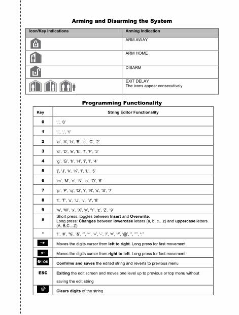
Arming and Disarming the System
Icon/Key Indications Arming Indication
ARM AWAY
ARM HOME
DISARM
EXIT DELAY The icons appear consecutively
Programming Functionality Key String Editor Functionality
0 ‘.’, ‘0’
1 ‘.’, ‘,’, ‘1’
2 ‘a’, ‘A’, ‘b’, ‘B’, ‘c’, ‘C’, ‘2’
3 ‘d’, ‘D’, ‘e’, ‘E’, ‘f’, ‘F’, ‘3’
4 ‘g’, ‘G’, ‘h’, ‘H’, ‘i’, ‘I’, ‘4’
5 ‘j’, ‘J’, ‘k’, ‘K’, ‘l’, ‘L’, ‘5’
6 ‘m’, ‘M’, ‘n’, ‘N’, ‘o’, ‘O’, ‘6’
7 ‘p’, ‘P’, ‘q’, ‘Q’, ‘r’, ‘R’, ‘s’, ‘S’, ‘7’
8 ‘t’, ‘T’, ‘u’, ‘U’, ‘v’, ‘V’, ‘8’
9 ‘w’, ‘W’, ‘x’, ‘X’, ‘y’, ‘Y’, ‘z’, ‘Z’, ‘9’
# Short press: toggles between Insert and Overwrite. Long press: Changes between lowercase letters (a, b, c…z) and uppercase letters (A, B,C…Z)
* ‘!’, ‘#’, ‘%’, ‘&’, ‘’’, ‘*’, ‘+’, ‘-’, ‘/’, ‘=’, ‘^’, ‘@’, ‘’, ‘”’, “:”
Moves the digits cursor from left to right. Long press for fast movement
Moves the digits cursor from right to left. Long press for fast movement
Confirms and saves the edited string and reverts to previous menu
ESC Exiting the edit screen and moves one level up to previous or top menu without
saving the edit string
Clears digits of the string
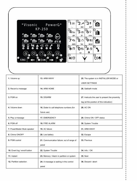
1. Volume up 13. ARM AWAY 25. The system is in INSTALLER MODE or
USER SETTINGS
2. Record a message 14. ARM HOME 26. Sabbath mode
3. PGM on 15. DISARM 27. Instructs the user to present the proximity
tag (at the position of this indication)
4. Volume down 16. Dialer to call telephone numbers (for
future use)
28. AC ON
5. Play a message 17. EMERGENCY 29. Chime ON / OFF status
6. PGM off 18. FIRE ALARM 30. System Trouble
7. PowerMaster Mute speaker 19. AC failure 31. ARM AWAY
8. Chime ON/OFF 20. Low battery 32. Escape
9. PGM control 21. Communication failure: out of range of
panel
33. Previous
10. Event log / enroll button 22. System Trouble 34. Info. / OK
11. Instant 23. Memory / Alarm in partition or system 35. Next
12. Partition selection 24. A message is waiting in the control
panel
36. Discard / abort

Installer’s Guide Keypad Installer’s Guide Keypad Installer’s Guide Keypad Installer’s Guide Keypad Installer’s Guide Keypad Installer’s Guide Keypad Installer’s Guide
Keypad Installer’s Guide Keypad Installer’s Guide Keypad Installer’s Guide Keypad Installer’s Guide Keypad Installer’s Guide Keypad Installer’s Guide Keypad Installer’s
Guide Keypad Installer’s Guide Keypad Installer’s Guide Keypad Installer’s Guide Keypad Installer’s Guide Keypad Installer’s Guide Keypad Installer’s Guide Keypad
Installer’s Guide Keypad Installer’s Guide Keypad Installer’s Guide Keypad Installer’s Guide Keypad Installer’s Guide Keypad Installer’s Guide Keypad Installer’s Guide
Keypad Installer’s Guide Keypad Installer’s Guide Keypad Installer’s Guide Keypad Installer’s Guide Keypad Installer’s Guide Keypad Installer’s Guide Keypad Installer’s
Guide Keypad Installer’s Guide Keypad Installer’s Guide Keypad Installer’s Guide Keyp
© 201
ad Installer’s Guide Keypad Installer’s Guide Keypad Installer’s Guide Keypad Installer’s Guide Keypad Installer’s Guide Keypad Installer’s Guide Keypad Installer’s
Guide Keypad Installer’s Guide Keypad Installer’s Guide Keypad Installer’s Guide Keypad Installer’s Guide Keypad Installer’s Guide Keypad Installer’s Guide Keypad
Installer’s Guide Keypad Installer’s Guide Keypad Installer’s Guide Keypad Installer’s Guide Keypad Installer’s Guide Keypad Installer’s Guide Keypad Installer’s Guide
Keypad Installer’s Guide Keypad Installer’s Guide Keypad Installer’s Guide Keypad Installer’s Guide Keypad Installer’s Guide Keypad Installer’s Guide Keypad Installer’s
Guide Keypad Installer’s Guide Keypad Installer’s Guide Keypad Installer’s Guide Keypad Installer’s Guide Keypad Installer’s Guide Keypad Installer’s Guide Keypad
Installer’s Guide Keypad Installer’s Guide Keypad Installer’s Guide Keypad Installer’s Guide Keypad Installer’s Guide Keypad Installer’s Guide Keypad Installer’s Guide
Keypad Installer’s Guide Keypad Installer’s Guide Keypad Installer’s Guide Keypad Installer’s Guide Keypad Installer’s Guide Keypad Installer’s Guide Keypad Installer’s
Guide Keypad Installer’s Guide Keypad Installer’s Guide Keypad Installer’s Guide Keypad Installer’s Guide Keypad Installer’s Guide Keypad Installer’s Guide Keypad
Installer’s Guide Keypad Installer’s Guide Keypad Installer’s Guide Keypad Installer’s Guide Keypad Installer’s Guide Keypad Installer’s Guide Keypad Installer’s Guide
Keypad Installer’s Guide Keypad Installer’s Guide Keypad Installer’s Guide Keypad Installer’s Guide Keypad Installer’s Guide Keypad Installer’s Guide Keypad Installer’s
Guide Keypad Installer’s Guide Keypad Installer’s Guide Keypad Installer’s Guide Keypad Installer’s Guide Keypad Installer’s Guide Keypad Installer’s Guide Keypad
Installer’s Guide Keypad Installer’s Guide Keypad Installer’s Guide Keypad Installer’s Guide Keypad Installer’s Guide Keypad Installer’s Guide Keypad Installer’s Guide
Keypad Installer’s
www.visonic.comContact Visonic for further information:[email protected]
INS
TAL
LE
R
GU
ID
E
K e y p a d I n s t a l l e r ' s G u i d e
K P - 2 5 0 P G 2
© 2017 Tyco S
ecurity Products. A
ll rights reserved. KP
-250 PG
2 English Installer G
uide D-306919
INSTALLER GUIDE