Embed Size (px)
Citation preview

Draf
t Ken
ya S
tand
ard
for B
allot
ing —
Not
to b
e Ci
ted
as K
enya
Sta
ndar
d
KENYA STANDARD KS 1876-1:2010 ICS 29.240.20
© KEBS 2010 First Edition 2010
Electrical power transmission and distribution — Overhead power lines for conditions prevailing in Kenya — Part 1: Code of practice
BALLOT DRAFT, MAY 2010
Draf
t Ken
ya S
tand
ard
for B
allot
ing —
Not
to b
e Ci
ted
as K
enya
Sta
ndar
d
KS 1876-1:2010
ii © KEBS 2010 — All rights reserved
TECHNICAL COMMITTEE REPRESENTATION The following organizations were represented on the Technical Committee: Nairobi City Council, City Engineer’s Department. Jomo Kenyatta University of Agriculture and Technology Kenya Polytechnic Kenya Power & Lighting Company Fluid & Power Systems Ltd Ministry of Public Works and Housing Ministry of Energy Kenafric Industries Ltd Power Technics Ltd Rural Electrification Authority The Energy Regulatory Commission Consumer Information Network Kenya Association of Manufacturers Institute of Engineers of Kenya Kenya Electricity Generating Company Ltd ABB LTD Switchgear & Controls Ltd Power Controls Ltd Communications Communication of Kenya Instrument Ltd Kenya Pipeline Company Ltd Telkom Kenya Ltd Meteorological Department Kenya Bureau of Standards — Secretariat
REVISION OF KENYA STANDARDS In order to keep abreast of progress in industry, Kenya standards shall be regularly reviewed. Suggestions for improvement to published standards, addressed to the Managing Director, Kenya Bureau of Standards, are welcome.
© Kenya Bureau of Standards, 2010 Copyright. Users are reminded that by virtue of Section 25 of the Copyright Act, Cap. 12 of 2001 of the Laws of Kenya, copyright subsists in all Kenya Standards and except as provided under Section 26 of this Act, no Kenya Standard produced by Kenya Bureau of Standards may be reproduced, stored in a retrieval system in any form or transmitted by any means without prior permission in writing from the Managing Director.

Draf
t Ken
ya S
tand
ard
for B
allot
ing —
Not
to b
e Ci
ted
as K
enya
Sta
ndar
d
KENYA STANDARD KS 1876-1:2010 ICS 29.240.20
© KEBS 2010 — All rights reserved iii
Electrical power transmission and distribution — Overhead power lines for conditions prevailing in Kenya — Part 1: Code of practice
KENYA BUREAU OF STANDARDS (KEBS)
Head Office: P.O. Box 54974, Nairobi-00200, Tel.: (+254 020) 605490, 69028000, 602350, Mobile: 0722202137/8, 0734600471/2;
Fax: (+254 020) 604031 E-Mail: [email protected], Web:http://www.kebs.org
KEBS Coast Region P.O. Box 99376, Mombasa 80100 Tel: (+254 041) 229563, 230939/40 Fax: (+254 041) 229448 E-mail: [email protected]
KEBS Lake Region P.O. Box 2949, Kisumu 40100 Tel: (+254 057) 23549,22396 Fax: (+254 057) 21814 E-mail: [email protected]
KEBS North Rift Region P.O. Box 2138, Nakuru 20100 Tel: (+254 051) 210553, 210555

Draf
t Ken
ya S
tand
ard
for B
allot
ing —
Not
to b
e Ci
ted
as K
enya
Sta
ndar
d
KS 1876-1:2010
iv © KEBS 2010 — All rights reserved
F O R E W O R D
This Kenya standard was prepared by the Switchgear and Distribution Equipment in accordance with the procedures of the Bureau and is in compliance with Annex 3 of the WTO/TB Agreement. This standard was prepared to enable competent and prescribed persons to design safe and cost-effective power lines by its quoting of the statutory requirements applicable and indicating the current technology and practice related to Kenyan conditions. It is not intended to be a textbook on the design of overhead lines for Kenyan conditions but to draw attention to the various factors which should be borne in mind in the design and construction of power lines and to indicate ways and means of overcoming certain of the difficulties that can be encountered. It also provides guidance when the optimization of power lines is required for the varying climatic conditions within Kenya and for which exemption from the OHS Act, 2007, is necessary. In the development of this standard, the South African Standard, SANS 10280:2001, Overhead power lines for conditions prevailing in South Africa — Code of practice, was extensively consulted. Assistance derived from this source is hereby acknowledged. Normative and informative annexes A 'normative' annex is an integral part of a standard, whereas an 'informative' annex is only for information and guidance. Summary of development
This Kenya Standard, having been prepared by the Switchgear and Distribution Equipment Technical Committee was first approved by the National Standards Council in June 2010
Amendments issued since publication
Amd. No. Date Text affected
Draf
t Ken
ya S
tand
ard
for B
allot
ing —
Not
to b
e Ci
ted
as K
enya
Sta
ndar
d
KS 1876-1:2010
© KEBS 2010 — All rights reserved v
Contents 1 Scope .................................................................................................................................................... 1 2 Normative references ........................................................................................................................... 1 3 Definitions ............................................................................................................................................. 1 4 General requirements ........................................................................................................................... 3 4.1 Standards to be observed .................................................................................................................... 3 4.2 Basic conditions of design .................................................................................................................... 3 4.3 Protection against hazards ................................................................................................................... 4 4.4 Combined and parallel routes ............................................................................................................... 5 4.5 Inductive and electrostatic interference with communication circuits ................................................... 6 4.6 Electrolytic corrosion............................................................................................................................. 7 5 Conductors and earth wires .................................................................................................................. 7 5.1 Material ................................................................................................................................................. 7 5.2 Maximum tensions ................................................................................................................................ 8 5.3 Joints .................................................................................................................................................. 10 6 Supports and fittings ........................................................................................................................... 10 6.1 Factors of safety ................................................................................................................................. 10 6.2 Design loading .................................................................................................................................... 10 6.3 Loading due to broken conductors ..................................................................................................... 12 6.4 Erection loads ..................................................................................................................................... 13 6.5 Foundations ........................................................................................................................................ 14 6.6 Insulators and fittings .......................................................................................................................... 15 6.7 Clearances .......................................................................................................................................... 16 6.8 Stay wires ........................................................................................................................................... 19 7 Crossings ............................................................................................................................................ 20 7.1 Crossings over roads, railways, tramways and communication lines ................................................ 20 7.2 Crossings over water .......................................................................................................................... 20 7.3 Joints in crossings .............................................................................................................................. 21 7.4 Crossings over other services ............................................................................................................ 21 8 Earthing .............................................................................................................................................. 21 8.1 Support structures for power lines ...................................................................................................... 21 8.2 Fittings ................................................................................................................................................ 21 8.3 Earth wires .......................................................................................................................................... 21 9 Procedure to be adopted before the construction of power lines ....................................................... 23 9.1 General ............................................................................................................................................... 23 9.2 Environmental impact ......................................................................................................................... 23 9.3 Telecommunications authority ............................................................................................................ 23 9.4 Appropriate road authority .................................................................................................................. 23 9.5 Civil Aviation Authority ........................................................................................................................ 23 9.6 Other electricity supply authorities ...................................................................................................... 23 Annex A (normative) Principal Acts, ordinances, regulations and instructions pertaining to overhead power lines ............................................................................................................................................................ 24 Annex B (normative) Guidance on power lines and communication circuits ................................................. 25 Annex C (informative) Clearances required for power lines that cross other services .................................. 31

Draf
t Ken
ya S
tand
ard
for B
allot
ing —
Not
to b
e Ci
ted
as K
enya
Sta
ndar
d

Draf
t Ken
ya S
tand
ard
for B
allot
ing —
Not
to b
e Ci
ted
as K
enya
Sta
ndar
d
KENYA STANDARD KS 1876-1:2010
© KEBS 2010 — All rights reserved 1
Electrical power transmission and distribution — Ov erhead power lines for conditions prevailing in Kenya — Part 1: Code o f practice 1 Scope This Kenya Standard identifies the various factors to be taken into account in the design and construction of overhead power lines, and indicates ways and means of overcoming certain of the difficulties that can be encountered. 2 Normative references The following referenced documents are indispensable for the application of this Kenya Standard. For dated references, only the edition cited applies. For undated references, the latest edition of the referenced document (including any amendments) applies. ISO 11303, Corrosion of metals and alloys — Guidelines for selection of protection methods against atmospheric corrosion ISO 12944, Paints and varnishes — Corrosion protection of steel structures by protective paint systems ISO 14713, Protection against corrosion of iron and steel in structures — Zinc and aluminium coatings — Guidelines ISO 17834, Thermal spraying — Coatings for protection against corrosion and oxidation at elevated temperatures ISO 19840, Paints and varnishes — Corrosion protection of steel structures by protective paint systems — Measurement of, and acceptance criteria for, the thickness of dry films on rough surfaces KS 1886, Electrical power transmission and distribution — Transmission structure foundation — Design and testing KS 1889, Electrical power transmission and distribution — Installation of foundations for transmission line structures — Guide IEC 60383-1, Insulators for overhead lines with a nominal voltage above 1 000 V — Part 1: Ceramic or glass insulator units for a. c. systems — Definitions, test methods and acceptance criteria IEC 60815, Guide for the selection of insulators in respect of polluted conditions IEC 60071-1, Insulation co-ordination — Part 1: Definitions, principles and rules IEC 60071-2, Insulation co-ordination — Part 2: Application guide IEC 60826, Loading and strength of overhead transmission lines 3 Definitions For the purposes of this standard the following definitions apply: 3.1 basic insulation level (BIL) A specific insulation level, expressed in kilovolts, to which the complete system is designed and constructed. This insulation level includes the line pole insulation to earth at every pole, the insulation levels of the switchgear, line isolators and reclosers, and the insulation level of substations connected to the system, including their transformers.

Draf
t Ken
ya S
tand
ard
for B
allot
ing —
Not
to b
e Ci
ted
as K
enya
Sta
ndar
d
KS 1876-1:2010
2 © KEBS 2010 — All rights reserved
3.2 communication lines Lines that convey information by electrical means 3.3 earthed So connected to the general mass of earth that, where practicable, when contact is made anywhere on the line between a live conductor and earthed metal, the resultant current is not less than that required to operate the devices which interrupt the supply to the line 3.4 extra-high voltage (EHV) A set of nominal voltage levels in the range 220 kV < Un < 400 kV 3.5 factor of safety (of any component) The ratio of a component's failing load to the maximum working load for which it is designed 3.6 footing resistance The resistance between a structure and earth 3.7 high voltage (HV) A set of nominal voltage levels in the range 44 kV < Un < 220 kV 3.8 low voltage (LV) A set of nominal voltage levels that are used for the distribution of electricity the upper limit of which is generally accepted to be an a.c. voltage of 1 000 V (or a d.c. voltage of 1 500 V) 3.9 medium voltage (MV) A set of nominal voltage levels in the range 1 kV < Un < 44 kV that lie above low voltage and below high voltage 3.10 power line An overhead line erected to convey electrical energy for any purpose other than communication, but excluding the overhead contact or catenary wires of an electric traction system. 3.11 service connection The conductors between the supplier's mains and the customer's installation. In the case of an overhead service connection, this means the conductor between a supply-line pole and the customer's installation. 3.12 standard specification A Kenya Standard specification issued in terms of the Standards Act, Cap 496 of the Laws of Kenya 3.13 stay A steel wire, rope or rod, working under tension, that connects a point of a support to a separate anchor 3.14 telecommunications authority the Communications Commission of Kenya 3.15 ultra-high voltage (UHV) A set of nominal voltage levels in the range Un > 400 kV, that are used in power systems for the bulk transmission of electricity.
Draf
t Ken
ya S
tand
ard
for B
allot
ing —
Not
to b
e Ci
ted
as K
enya
Sta
ndar
d
KS 1876-1:2010
© KEBS 2010 — All rights reserved 3
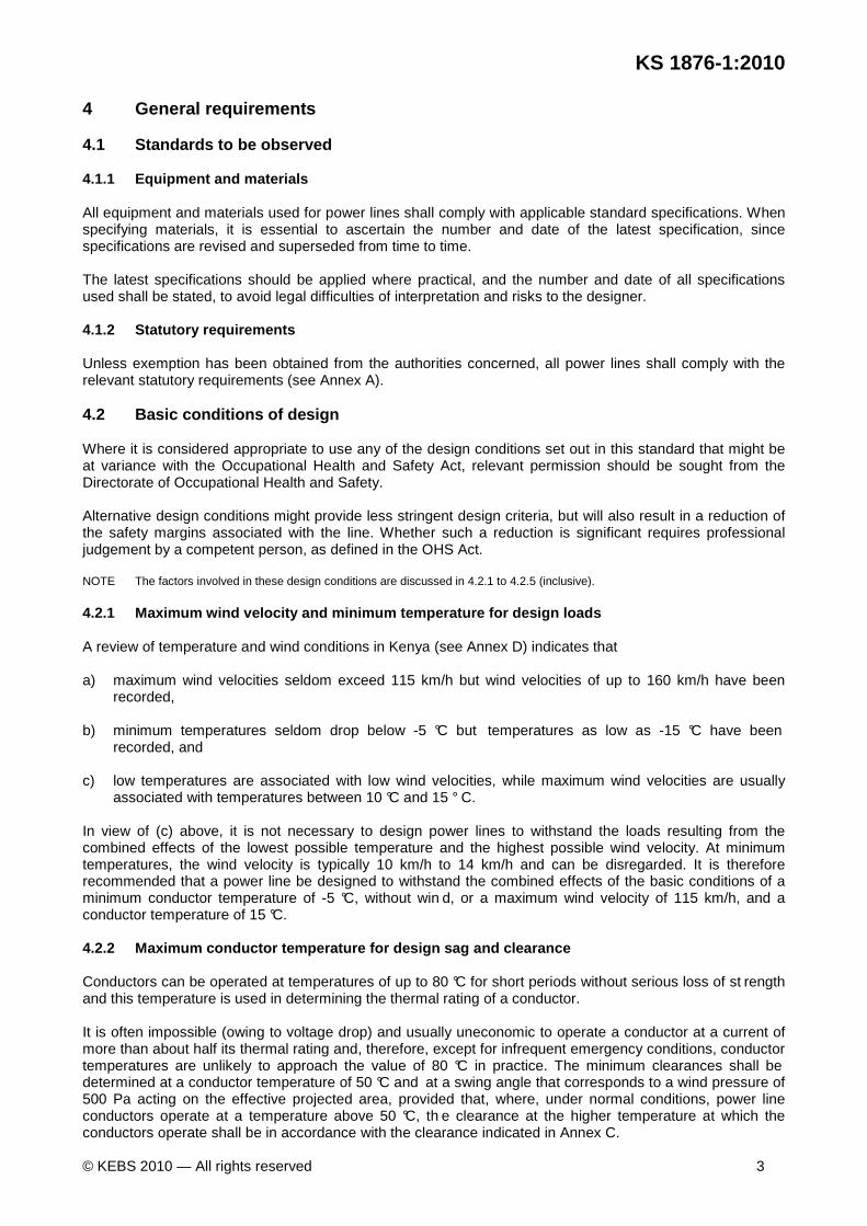
4 General requirements 4.1 Standards to be observed 4.1.1 Equipment and materials All equipment and materials used for power lines shall comply with applicable standard specifications. When specifying materials, it is essential to ascertain the number and date of the latest specification, since specifications are revised and superseded from time to time. The latest specifications should be applied where practical, and the number and date of all specifications used shall be stated, to avoid legal difficulties of interpretation and risks to the designer. 4.1.2 Statutory requirements Unless exemption has been obtained from the authorities concerned, all power lines shall comply with the relevant statutory requirements (see Annex A). 4.2 Basic conditions of design Where it is considered appropriate to use any of the design conditions set out in this standard that might be at variance with the Occupational Health and Safety Act, relevant permission should be sought from the Directorate of Occupational Health and Safety. Alternative design conditions might provide less stringent design criteria, but will also result in a reduction of the safety margins associated with the line. Whether such a reduction is significant requires professional judgement by a competent person, as defined in the OHS Act. NOTE The factors involved in these design conditions are discussed in 4.2.1 to 4.2.5 (inclusive). 4.2.1 Maximum wind velocity and minimum temperature for design loads A review of temperature and wind conditions in Kenya (see Annex D) indicates that a) maximum wind velocities seldom exceed 115 km/h but wind velocities of up to 160 km/h have been
recorded, b) minimum temperatures seldom drop below -5 °C but temperatures as low as -15 °C have been
recorded, and c) low temperatures are associated with low wind velocities, while maximum wind velocities are usually
associated with temperatures between 10 °C and 15 ° C. In view of (c) above, it is not necessary to design power lines to withstand the loads resulting from the combined effects of the lowest possible temperature and the highest possible wind velocity. At minimum temperatures, the wind velocity is typically 10 km/h to 14 km/h and can be disregarded. It is therefore recommended that a power line be designed to withstand the combined effects of the basic conditions of a minimum conductor temperature of -5 °C, without win d, or a maximum wind velocity of 115 km/h, and a conductor temperature of 15 °C. 4.2.2 Maximum conductor temperature for design sag and clearance Conductors can be operated at temperatures of up to 80 °C for short periods without serious loss of st rength and this temperature is used in determining the thermal rating of a conductor. It is often impossible (owing to voltage drop) and usually uneconomic to operate a conductor at a current of more than about half its thermal rating and, therefore, except for infrequent emergency conditions, conductor temperatures are unlikely to approach the value of 80 °C in practice. The minimum clearances shall be determined at a conductor temperature of 50 °C and at a swing angle that corresponds to a wind pressure of 500 Pa acting on the effective projected area, provided that, where, under normal conditions, power line conductors operate at a temperature above 50 °C, th e clearance at the higher temperature at which the conductors operate shall be in accordance with the clearance indicated in Annex C.

Draf
t Ken
ya S
tand
ard
for B
allot
ing —
Not
to b
e Ci
ted
as K
enya
Sta
ndar
d
KS 1876-1:2010
4 © KEBS 2010 — All rights reserved
Current general practice is to use a maximum conductor temperature of not less than 60 °C when a line is being templated. 4.2.3 Design wind pressure The wind pressure on power lines depends on many variable factors, such as the gust component of the wind, the height of the supporting structure and of the conductor, and the shape of the power line components. Since the governing factors vary in each particular case, it is not possible to state exactly what pressure corresponds to a given maximum wind velocity. In practice, high-velocity winds are never constant but are made up of a steady component on which an alternating gust component is superimposed. In the case of a power line conductor, the force on a span of conductor owing to a gust will be less than that calculated, on the assumption that the maximum wind velocity occurs over the entire span. This is because the width of a gust is limited. Hence, in the case of conductors, a gust factor of 0.6 is used in calculating wind pressure. In the case of structures, it is assumed that a gust will affect the entire structure, and hence no gust factor is applied. In the case of structures of height up to 20 m, the methods given in KS 1877 and KS 1878-3 should be used for calculating wind pressure. In the case of structures of height between 20 m and 50 m, a realistic basic wind pressure (BWP) in the case of a wind of maximum velocity 115 km/h is 1 170 Pa for all span lengths. The actual design wind pressures (DWP) that should be applied to the different line components are calculated as shown in 6.2.1 and 6.2.2. In the case of structures of height exceeding 50 m, specialist design is needed.
NOTE 1 See KS 1877 and KS 1878-3 for guidance on designing wooden pole structures for MV and LV lines.
NOTE 2 In the case of structures of height exceeding 50 m, specialist designs are needed.
Numerous methods and references exist for the determination of the wind pressure to be used, based on the measurement of wind velocities. Many of these methods are empirical and might not reflect local conditions. 4.2.4 Ice loading The formation of ice on power lines is a rare occurrence in Kenya and is therefore not included in the basic design conditions. In isolated areas where ice is known to occur, it is usually possible to use lines designed for basic conditions of no ice and to use shorter spans adjusted for the increase in weight due to ice, to ensure that the required clearances and a reasonable factor of safety will be obtained under ice-loaded conditions.
The increase in diameter owing to ice can be disregarded, since the corresponding wind velocities are low. Further information is contained in KS IEC 60826. 4.2.5 Unusual conditions The basic conditions of design and the factors of safety recommended in this standard have been so chosen that a design that embodies these basic conditions should be able to withstand, with a reduced but adequate factor of safety, any unusual conditions that can be visualized in Kenya, provided that these conditions occur infrequently. If power lines are to be erected in areas where conditions are frequently more onerous than assumed in the basic design conditions, consideration should be given to modifying the design specifications accordingly. 4.3 Protection against hazards 4.3.1 Calculation of swing
The conductor swing shall be determined in accordance with Annex C or shall satisfy the conditions of 4.4.1, and the most onerous condition shall be used to determine the design clearance.

Draf
t Ken
ya S
tand
ard
for B
allot
ing —
Not
to b
e Ci
ted
as K
enya
Sta
ndar
d
KS 1876-1:2010
© KEBS 2010 — All rights reserved 5
4.3.2 Proximity to buildings Where the erection of power lines over or near to buildings is unavoidable, the clearance from the building to the nearest live conductor shall be not less than that determined in accordance with Annex C. 4.3.3 Proximity to explosive magazines To comply with the statutory requirements, when a power line is erected in the vicinity of an explosive magazine, the power line shall be separated from the magazine by a horizontal distance of not less than: a) 15 m in the case of power lines that have spans of up to 30 m; b) 20 m in the case of power lines that have spans exceeding 30 m and up to 150 m; and c) 30 m in the case of power lines that have spans exceeding 150 m. It might be necessary to increase this distance if so required. 4.3.4 Service connections Where service connections are required, they shall be provided in accordance with applicable regulations recommended by the Energy Regulatory Commission. 4.3.5 Anti-climbing devices Power line supports that can readily be climbed unaided shall be adequately protected to prevent unauthorized persons from reaching a live conductor. Anti-climbing devices should be installed as low as possible, but not within 3 m of the ground. 4.3.6 Power lines erected parallel to a tram route or trolley-bus route If a power line is erected parallel to a tram route or trolley-bus route, the elevation and location of the conductors should, wherever practicable, be such that contact cannot be made with a trolley boom that has left its trolley wire. 4.4 Combined and parallel routes 4.4.1 Independent structures If an overhead communication line and a power line or if two power lines are erected parallel to each other along the same route, the separation between lines shall be such that, with both lines healthy, the clearance between any conductor of the higher-voltage line and any conductor or earth wire of the lower-voltage line is never less than the minimum phase-to-phase clearance applicable to the higher-voltage line. This clearance shall be maintained for all conditions up to maximum sag and maximum sideswing of the conductors of either line, assuming that the other line remains in the templated position for still air, and maximum sideswing occurs at design wind pressure at a minimum conductor temperature of the higher of 40 °C and 30 °C lower than the templating temperature. 4.4.2 Common structures If lines are erected one above the other on common structures, the higher-voltage line shall be above the lower-voltage line or communication line, and the vertical separation between the nearest conductors of any two lines shall be in accordance with the phase-to-phase clearances given in Annex C for the higher-voltage line. It is recommended that the conductors of an LV overhead line be in vertical configuration in order to maximize the chance of the occurrence of a permanent fault with resultant isolation, should a wire break. NOTE 1 Particular attention to ensure compliance with statutory clearances (see Table C.1 of Annex C) will be necessary in cases where a higher-mounted line could operate at full load (maximum sag) with a lower-mounted line at ambient temperature. An aerial bundled conductor may be considered to be an insulated cable for determining clearances.

Draf
t Ken
ya S
tand
ard
for B
allot
ing —
Not
to b
e Ci
ted
as K
enya
Sta
ndar
d
KS 1876-1:2010
6 © KEBS 2010 — All rights reserved
4.4.3 Protective earthing of parallel lines under c onstruction The degree of earthing protection required for a given line under construction is dependent upon the degree of exposure to electrical hazards that exist within the construction area. For a project in an area exposed to one or more energized lines where electrical contact could occur, extensive earthing requirements are needed. The methods used for earthing depend on the degree of exposure to electrical hazards and on the soil conditions at the site. For adequate protection of personnel, all equipment, conductors, anchors and structures within the work area shall be bonded together and to earth. All earthing devices shall be so sized as to withstand the largest induced current that could be expected owing to fault current on the energized line. The clamps selected for earthing cables shall have a current capability equal to that of the cable. The earthing connection to ground shall be so arranged as to ensure its continuity in the event of disconnection of any equipment earthing conductor. NOTE Even where electrical contact is not considered a hazard, it is necessary to provide sufficient earthing such that electric shock caused by induced voltages from a nearby energized line is avoided. 4.5 Inductive and electrostatic interference with c ommunication circuits 4.5.1 Submission to the telecommunications authorit y Details of all proposed power lines shall be submitted to the telecommunications authority for approval. The way in which application is to be made is set out in Clause 9. 4.5.2 Noise induction In general, the power required to operate communication equipment is very little and its operation can be impaired by relatively small voltages induced in the wires of a communication circuit that is parallel to a power circuit. Harmonics both of voltage and of current can be particularly objectionable, since the former cause electrostatic interference and the latter cause electromagnetic interference with communication circuits. The telecommunications authority is prepared to assist in carrying out tests to determine the presence and magnitude of harmonics in a supply system if interference from this source is suspected. Telephone noise can be mitigated to some extent by the application of a well-designed and well-coordinated transposition system to the communication circuits. The horizontal separation between the power line and the telephone line should be in accordance with Figures B.1, B.2, B.3 and B.4 of Annex B. See Annex B for further information. 4.5.3 Minimum separating distances from a safety as pect 4.5.3.1 Induced voltages that result from the proximity of an electricity supply plant can appear on systems and equipment other than those intended for communication. Personnel who have access to such systems and equipment shall be able to work in safety at all times. The distance between the power-frequency carrier and other systems (telecommunications, railways, pipelines, etc.) shall grant the level of immunity required in safety regulations (see Annex A), without reference to the power-frequency carrier operator. These limits require that induced voltages shall not exceed a) an r.m.s. voltage of 50 V in steady state, b) an r.m.s. voltage of 430 V on power lines where an earth fault is cleared in more than 0.5 s, c) an r.m.s. voltage of 1 000 V on power lines where an earth fault is cleared in 0.35 s to 0.5 s, or d) an r.m.s. voltage of 1 200 V on power lines where an earth fault is cleared in less than 0.35 s. 4.5.3.2 Wherever practical, the separation between lines shall be such that, should either line overturn, it will not touch any part of the adjacent line. If this separation cannot be provided, the supports of the line that could touch the other line shall be designed to withstand the broken-wire condition of 6.3.

Draf
t Ken
ya S
tand
ard
for B
allot
ing —
Not
to b
e Ci
ted
as K
enya
Sta
ndar
d
KS 1876-1:2010
© KEBS 2010 — All rights reserved 7
4.6 Electrolytic corrosion In areas where d.c. traction services exist, there is a risk that stray currents might enter the earthing system of a power line at one point, be transmitted along its earth wires or counterpoise and leave at some remote point where the power line crosses, or is close to, a buried pipeline or cable route. Where this possibility exists, agreement should be reached with the authority responsible for the other service, with regard to protective measures to reduce the risk of electrolytic corrosion to the metalwork of either system. The protective measures adopted will depend on the particular circumstances, but will usually take the form of separating the two systems by an agreed minimum distance and providing interposing insulating material. Corrosion protection measures shall comply with ISO 11303, ISO 12944, ISO 14713, ISO 17834 and ISO 19840 5 Conductors and earth wires 5.1 Material 5.1.1 Corrosion All conductors and earth wires shall be of materials that have adequate corrosion resistance to the atmosphere to which they are likely to be exposed in service, or shall be suitably protected against corrosion. Copper should always be installed below aluminium because copper salts washed down by rain will attack aluminium. Particular attention should be paid to the possibility of corrosion where dissimilar metals are in contact with one another. 5.1.2 Minimum size The minimum size of the conductor or, in the case of high-voltage lines, the minimum size of the bundle, shall be determined by the following key factors: a) the thermal rating (power transfer capacity) that is necessary, including consideration of the effects of
contingency outages on other system lines (reliability and stability criteria); and b) the short-circuit current. The size of the phase single conductor or of the phase bundle shall be selected to limit voltage drop, audible noise, radio interference, television interference and loss due to corona. 5.1.3 Current-carrying capacity 5.1.3.1 Operational states The following are the three main operational states for which current-carrying capacity calculations can be done: a) long duration/normal operation: it is preferable to limit the conductor temperature to between 50 °C and
60 °C. b) emergency operation: where it is expected that normal current-carrying capacity will be exceeded
temporarily for more than 20 min, a steady-state conductor temperature of up to 80 °C can be assumed. c) short-duration emergency operation: where temperatures exceeding 80 °C are assumed, the thermal
behaviour shall be assumed to be adiabatic. 5.1.3.2 Calculation method Conventional calculation of current-carrying capacity is based on an approach that uses fixed, conservative assumptions of meteorological data. 5.1.3.3 Copper conductors In the case of copper conductors, the normal operating temperature limits should not be exceeded.
Draf
t Ken
ya S
tand
ard
for B
allot
ing —
Not
to b
e Ci
ted
as K
enya
Sta
ndar
d
KS 1876-1:2010
8 © KEBS 2010 — All rights reserved
5.2 Maximum tensions 5.2.1 Limits 5.2.1.1 Statutory limits The maximum tension in conductors and earth wires under the basic conditions of design (i.e. a temperature of -5 °C and a wind pressure of 700 Pa on a shape f actor of 0.6 of the projected area (see 4.2.3)) is limited to be not more than 40 % of the breaking strength of the conductors or earth wires under high wind and low temperature conditions. This tends to lead to the use of high steel content conductors (aluminium conductors, steel reinforced (ACSR)), which increase the mass and require stronger supports. 5.2.1.2 Alternative limits A more reasonable limit for maximum tension than that stated in 5.2.1.1 is an initial tension of 70 % of the conductor's ultimate strength. Tensions should be calculated both a) at the highest wind pressure, at a conductor temperature of 15 °C, and b) at a minimum conductor temperature of -5 °C, wit hout wind. In practice, the conductor tension will usually be limited by the vibration limiting requirements (see 5.2.1.3), and, generally in the initial stage after construction, does not exceed 40 % of the conductor's ultimate strength. 5.2.1.3 Reduced limits to avoid fatigue failure due to vibrations Conductors and earth wires can vibrate, for instance, when subjected to steady low-velocity winds in open terrain. One of the principal factors that lead to failure due to fatigue is the tension in the conductor during periods of vibration. Particularly in the case of copper conductors, the fatigue resistance of the metal depends to a large extent on the cold working to which the conductor was subjected during manufacture. If there is a possibility of conductor vibration, the risk of failure due to fatigue should be reduced by using a lower conductor tension than the maximum permitted by the statutory regulations. Tension limits for copper conductors, aluminium conductors, steel reinforced (ACSR), all aluminium alloy conductors (AAAC) and steel earth wires, which are representative of commonly used conductors, are given in 5.2.1.3.1 to 5.2.1.3.3. Since vibration takes place at low wind velocities, the limitations are all imposed on a "no-wind" basis. 5.2.1.3.1 Copper conductors The tension at 15 °C should not exceed 26 % of the ultimate tensile strength of the conductor. 5.2.1.3.2 ACSR and AAAC conductors If vibration dampers are not used and the lines have relatively short spans, typically under 200 m, the initial tension at -5 °C should not exceed 25 % of the ulti mate tensile strength of the conductor. When vibration dampers are used, the following limitations are recommended: a) the initial tension at -5 °C should not exceed 3 3.3 % of the ultimate tensile strength of the conductor; b) the initial tension at 15 °C should not exceed 2 5 % of the ultimate tensile strength of the conductor; and c) the final tension at 15 °C should not exceed 20 % of the ultimate tensile strength of the conductor. NOTE Whereas three limitations are recommended, it should be remembered that only one is effective in limiting the tension at any given span. Limitation (a) above is introduced to ensure that the tension at the minimum design temperature of-5 °C is kept within limits and is effective for very short spans where the effects of changes in temperature are large. Limitation (b) above limits the tension for intermediate spans and limitation (c) above provides a greater safety margin for lines with long spans.
Draf
t Ken
ya S
tand
ard
for B
allot
ing —
Not
to b
e Ci
ted
as K
enya
Sta
ndar
d
KS 1876-1:2010
© KEBS 2010 — All rights reserved 9
Additional dampers are not required for bundled conductors if the tension is below a certain value 7, proportional to the conductor weight:
T = 1 800 Mc where T is the limiting tension, in newtons; and Mc is the conductor weight per metre, in newtons per metre. In the case of single conductors, it is not economical to use this value to limit initial tensions, and current practice is to limit the final tensions. Initial tensions are limited by the support structure capacity on short spans. 5.2.1.3.3 Steel earth wires In the case of galvanized steel earth wires of minimum breaking strength in the range 700 MPa to 1100 MPa, the maximum tension at 15 °C should be such that th e stress in the earth wire does not exceed 180 MPa. This criterion permits the use of tensions (at 15 °C) of the following percentages of minimum breaking strength: a) 700 MPa wires: 25 %; and b) 1 100 MPa wires: 15%. Earth wires are often strung to match, approximately, the sag of the conductors, and, when the conductors are strung to the tension limits recommended for vibration, the earth wire tension limits stated above are usually not exceeded. If the limits are exceeded, satisfactory performance can usually be obtained by the addition of a damping device to the earth wires. Because the conductors generally have a higher thermal expansion coefficient than the earth wire, in cold weather the clearance between the two will reduce if the line is not operational. This could lead to flashovers when the line is energized. As an additional safety margin and also to improve the shield angle at midspan, earth wires should sag to 85 % of the sag of the conductors. 5.2.2 Sag charts Generally, the sag charts required will depend on the limits chosen for conductor tensions. Sag information should be obtained from the manufacturer of the chosen conductor, in order to produce charts. The correction table for increased time between stringing and regulating should also be obtained from the manufacturer of the chosen conductor. It is important that the tensions and assumptions used in templating also be used in the sag charts, and vice versa, otherwise reduced clearances or excessive tensions can result. 5.2.3 Creep Over a period of time, the tension in a conductor tends to reduce to a value below that at which it was initially strung, owing to creep or non-elastic stretch. The amount of creep that will be experienced depends upon the conductor tension, the procedure adopted during stringing and the electrical loading and temperature experienced by the conductor in service. Copper conductors and steel earth wires are occasionally prestretched before erection, to reduce the tendency to creep. In the case of aluminium conductors, it is usual to prepare initial (or stringing) charts and final charts in which a maximum allowance is made for creep. Since the actual creep might be small and never reach the final value, it is advisable to limit the tension to the maximum that will avoid vibration problems, rather than to initial tensions (see 5.2.1.3). This, however, is costly, and a trade-off between initial vibration problems and extra-high supports is required.
Draf
t Ken
ya S
tand
ard
for B
allot
ing —
Not
to b
e Ci
ted
as K
enya
Sta
ndar
d
KS 1876-1:2010
10 © KEBS 2010 — All rights reserved
5.3 Joints 5.3.1 All joints shall be such that their current-carrying capacity exceeds that of the conductors that are being joined. Tension joints shall have a breaking strength of at least 95 % of that of the conductor. 5.3.2 In areas that are conducive to corrosion, it is good practice to coat the joined ends and fill the fittings with chemically inert corrosion-inhibiting paste. 6 Supports and fittings NOTE Guy wires that form an integral part of a guyed structure (as opposed to a self-supporting structure) are not dealt with in this standard. 6.1 Factors of safety 6.1.1 Minimum factors of safety The factors of safety to be applied vary according to the type of structure and the type of load (see Table 1). The factors of safety given in Table 1 shall be applied in all cases where the basic conditions of design in this standard are applied. 6.1.2 Wooden structures Continuously loaded wooden members are those that have appreciable stresses applied to them all the time, normally owing to bending. They include cross-arms placed in bending stress due to the mass of conductors and insulators, or by the application of longitudinal forces in the conductors at stayed angle and terminal structures. Heavily loaded members of this type tend to take on a gradually increasing set owing to such forces and accordingly larger factors of safety are required. Members that have end-on loading due to the mass of conductors etc., are not considered to fall into the class of continuously loaded members, because the stresses due to this kind of loading are small. Non-continuously loaded members are those that are only intermittently or periodically stressed, for example poles subjected to bending stresses due to wind. 6.1.3 Other metal structures (e.g. aluminium) The same factors of safety apply as for steel (see Table 1). 6.1.4 Composite structures The individual components of composite structures shall have factors of safety as specified for the relevant materials in 6.1.2 and 6.1.3. 6.2 Design loading The total load on a support consists of transverse loads due to wind pressure on the conductors, earth wires, insulators and fittings and on the support itself; vertical loads due to the mass of these items; transverse and longitudinal loads due to the tension in conductors and earth wires; and transverse, longitudinal and vertical loads due to the tension in stay wires. 6.2.1 Wind loads on wires The transverse load on a support due to wind pressure on a conductor or earth wire may be assumed to be given by:
T1 = DWP × d × L1 × K × 0.6
where
T1 is the transverse load, in newtons;
Draf
t Ken
ya S
tand
ard
for B
allot
ing —
Not
to b
e Ci
ted
as K
enya
Sta
ndar
d
KS 1876-1:2010
© KEBS 2010 — All rights reserved 11
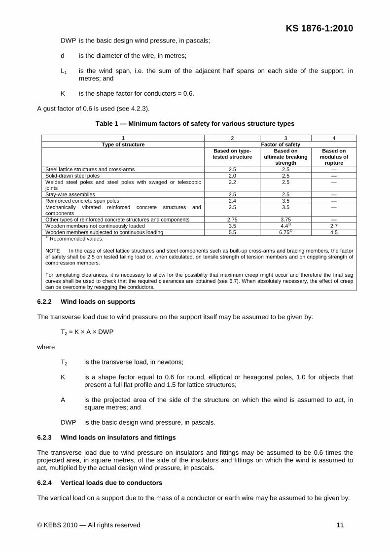
DWP is the basic design wind pressure, in pascals; d is the diameter of the wire, in metres; L1 is the wind span, i.e. the sum of the adjacent half spans on each side of the support, in
metres; and K is the shape factor for conductors = 0.6.
A gust factor of 0.6 is used (see 4.2.3).
Table 1 — Minimum factors of safety for various str ucture types
1 2 3 4 Type of structure Factor of safety
Based on type -tested structure
Based on ultimate breaking
strength
Based on modulus of
rupture Steel lattice structures and cross-arms 2.5 2.5 — Solid-drawn steel poles 2.0 2.5 — Welded steel poles and steel poles with swaged or telescopic joints
2.2 2.5 —
Stay-wire assemblies 2.5 2.5 — Reinforced concrete spun poles 2.4 3.5 — Mechanically vibrated reinforced concrete structures and components
2.5 3.5 —
Other types of reinforced concrete structures and components 2.75 3.75 — Wooden members not continuously loaded 3.5 4.41) 2.7 Wooden members subjected to continuous loading 5.5 6.751) 4.5 1) Recommended values. NOTE In the case of steel lattice structures and steel components such as built-up cross-arms and bracing members, the factor of safety shall be 2.5 on tested failing load or, when calculated, on tensile strength of tension members and on crippling strength of compression members. For templating clearances, it is necessary to allow for the possibility that maximum creep might occur and therefore the final sag curves shall be used to check that the required clearances are obtained (see 6.7). When absolutely necessary, the effect of creep can be overcome by resagging the conductors.
6.2.2 Wind loads on supports The transverse load due to wind pressure on the support itself may be assumed to be given by:
T2 = K × A × DWP where
T2 is the transverse load, in newtons; K is a shape factor equal to 0.6 for round, elliptical or hexagonal poles, 1.0 for objects that
present a full flat profile and 1.5 for lattice structures; A is the projected area of the side of the structure on which the wind is assumed to act, in
square metres; and DWP is the basic design wind pressure, in pascals.
6.2.3 Wind loads on insulators and fittings The transverse load due to wind pressure on insulators and fittings may be assumed to be 0.6 times the projected area, in square metres, of the side of the insulators and fittings on which the wind is assumed to act, multiplied by the actual design wind pressure, in pascals. 6.2.4 Vertical loads due to conductors The vertical load on a support due to the mass of a conductor or earth wire may be assumed to be given by:

Draf
t Ken
ya S
tand
ard
for B
allot
ing —
Not
to b
e Ci
ted
as K
enya
Sta
ndar
d
KS 1876-1:2010
12 © KEBS 2010 — All rights reserved
V = 9.81 × W × L2, where
V is the vertical load, in newtons; W is the mass of conductor per metre, in kilograms per metre; and L2 is the mass span, i.e. the sum of the adjacent half spans on each side of a support, in metres.
6.2.5 Vertical loads due to supports, insulators an d fittings The vertical load due to insulators, fittings and the support itself is that due to the mass of these items applied at the appropriate point. 6.2.6 Normal loads due to conductor tension In a line of approximately equal span lengths, the following loads are produced by conductor tension: a) longitudinal load on terminal structures : T
b) transverse load at angle structures : 2T sin 2
θ
c) tension in stay wire of terminal structure : T cosec β d) vertical load on terminal structure : T cot β where
T is the sum of maximum tensions in the conductors and earth wires, in newtons; θ is the angle of deviation of the line, in degrees; and β is the angle between the stay wire and the vertical, in degrees.
6.2.7 Loads due to differential tension In lines of unequal spans, there will be differences in the tension in different spans in conditions other than those existing at the time of stringing. These differences will be balanced at suspension structures by movement of the insulator strings but cannot be balanced at fixed intermediate points and at strain structures, except by movement of the structure itself. The unbalanced load from this cause is not likely to exceed 30 % of the tension in the wires at 15 °C in still air. Where considerable differences in span length are likely to be encountered, it is recommended that provision for unbalanced longitudinal load on strain structures be made in the design. This provision shall include load cases where the wind is assumed to act perpendicular to the longest span of a strain tower. 6.2.8 Horizontal loads due to stay wires Where stay wires are used, they are usually designed to counteract the normal loads imposed on a structure by tension in the conductors and earth wires. The horizontal component of tension in the stay wires can therefore be assumed to be equal to, and opposite to, the load discussed in 6.2.6. 6.3 Loading due to broken conductors The statutory regulations (see Annex A) do not lay down any requirements regarding broken conductor conditions, except in the case of crossings (see Clause 7). The question of what provision should be made for broken conductor conditions in the design of a power line is therefore a matter of individual choice.
Draf
t Ken
ya S
tand
ard
for B
allot
ing —
Not
to b
e Ci
ted
as K
enya
Sta
ndar
d
KS 1876-1:2010
© KEBS 2010 — All rights reserved 13
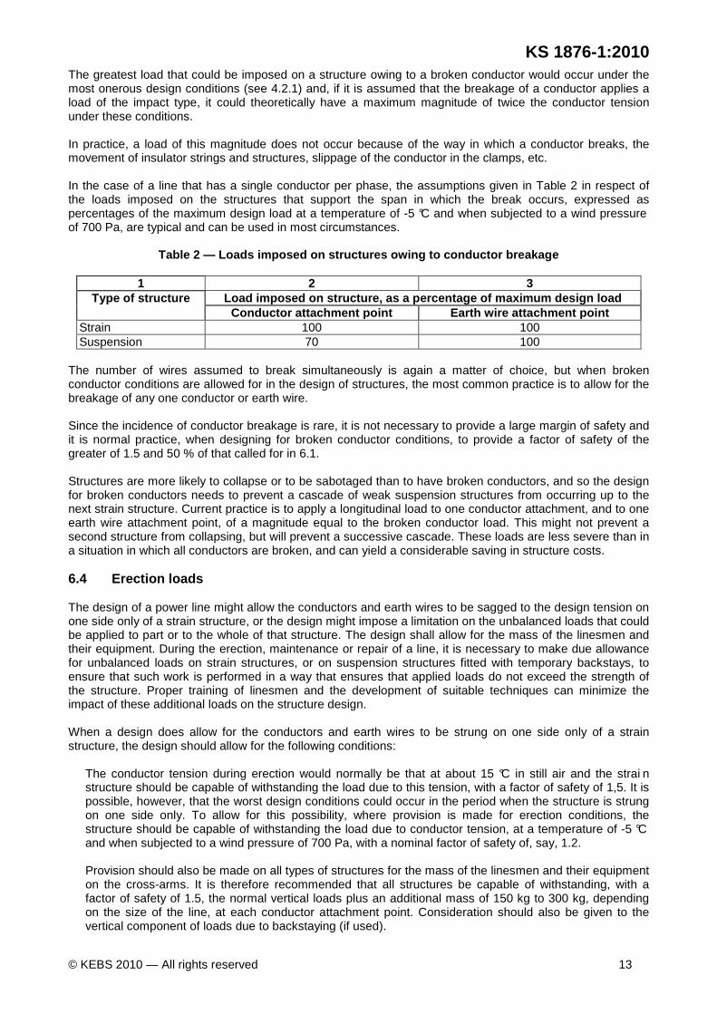
The greatest load that could be imposed on a structure owing to a broken conductor would occur under the most onerous design conditions (see 4.2.1) and, if it is assumed that the breakage of a conductor applies a load of the impact type, it could theoretically have a maximum magnitude of twice the conductor tension under these conditions. In practice, a load of this magnitude does not occur because of the way in which a conductor breaks, the movement of insulator strings and structures, slippage of the conductor in the clamps, etc. In the case of a line that has a single conductor per phase, the assumptions given in Table 2 in respect of the loads imposed on the structures that support the span in which the break occurs, expressed as percentages of the maximum design load at a temperature of -5 °C and when subjected to a wind pressure of 700 Pa, are typical and can be used in most circumstances.
Table 2 — Loads imposed on structures owing to cond uctor breakage
1 2 3 Type of structure Load imposed on structure, as a percentage of maxim um design load
Conductor attachment point Earth wire attachment point Strain 100 100 Suspension 70 100
The number of wires assumed to break simultaneously is again a matter of choice, but when broken conductor conditions are allowed for in the design of structures, the most common practice is to allow for the breakage of any one conductor or earth wire. Since the incidence of conductor breakage is rare, it is not necessary to provide a large margin of safety and it is normal practice, when designing for broken conductor conditions, to provide a factor of safety of the greater of 1.5 and 50 % of that called for in 6.1. Structures are more likely to collapse or to be sabotaged than to have broken conductors, and so the design for broken conductors needs to prevent a cascade of weak suspension structures from occurring up to the next strain structure. Current practice is to apply a longitudinal load to one conductor attachment, and to one earth wire attachment point, of a magnitude equal to the broken conductor load. This might not prevent a second structure from collapsing, but will prevent a successive cascade. These loads are less severe than in a situation in which all conductors are broken, and can yield a considerable saving in structure costs. 6.4 Erection loads The design of a power line might allow the conductors and earth wires to be sagged to the design tension on one side only of a strain structure, or the design might impose a limitation on the unbalanced loads that could be applied to part or to the whole of that structure. The design shall allow for the mass of the linesmen and their equipment. During the erection, maintenance or repair of a line, it is necessary to make due allowance for unbalanced loads on strain structures, or on suspension structures fitted with temporary backstays, to ensure that such work is performed in a way that ensures that applied loads do not exceed the strength of the structure. Proper training of linesmen and the development of suitable techniques can minimize the impact of these additional loads on the structure design. When a design does allow for the conductors and earth wires to be strung on one side only of a strain structure, the design should allow for the following conditions:
The conductor tension during erection would normally be that at about 15 °C in still air and the strai n structure should be capable of withstanding the load due to this tension, with a factor of safety of 1,5. It is possible, however, that the worst design conditions could occur in the period when the structure is strung on one side only. To allow for this possibility, where provision is made for erection conditions, the structure should be capable of withstanding the load due to conductor tension, at a temperature of -5 °C and when subjected to a wind pressure of 700 Pa, with a nominal factor of safety of, say, 1.2. Provision should also be made on all types of structures for the mass of the linesmen and their equipment on the cross-arms. It is therefore recommended that all structures be capable of withstanding, with a factor of safety of 1.5, the normal vertical loads plus an additional mass of 150 kg to 300 kg, depending on the size of the line, at each conductor attachment point. Consideration should also be given to the vertical component of loads due to backstaying (if used).
Draf
t Ken
ya S
tand
ard
for B
allot
ing —
Not
to b
e Ci
ted
as K
enya
Sta
ndar
d
KS 1876-1:2010
14 © KEBS 2010 — All rights reserved
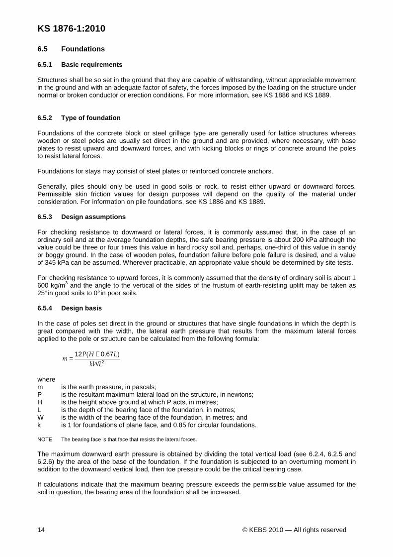
6.5 Foundations 6.5.1 Basic requirements Structures shall be so set in the ground that they are capable of withstanding, without appreciable movement in the ground and with an adequate factor of safety, the forces imposed by the loading on the structure under normal or broken conductor or erection conditions. For more information, see KS 1886 and KS 1889. 6.5.2 Type of foundation Foundations of the concrete block or steel grillage type are generally used for lattice structures whereas wooden or steel poles are usually set direct in the ground and are provided, where necessary, with base plates to resist upward and downward forces, and with kicking blocks or rings of concrete around the poles to resist lateral forces. Foundations for stays may consist of steel plates or reinforced concrete anchors. Generally, piles should only be used in good soils or rock, to resist either upward or downward forces. Permissible skin friction values for design purposes will depend on the quality of the material under consideration. For information on pile foundations, see KS 1886 and KS 1889. 6.5.3 Design assumptions For checking resistance to downward or lateral forces, it is commonly assumed that, in the case of an ordinary soil and at the average foundation depths, the safe bearing pressure is about 200 kPa although the value could be three or four times this value in hard rocky soil and, perhaps, one-third of this value in sandy or boggy ground. In the case of wooden poles, foundation failure before pole failure is desired, and a value of 345 kPa can be assumed. Wherever practicable, an appropriate value should be determined by site tests. For checking resistance to upward forces, it is commonly assumed that the density of ordinary soil is about 1 600 kg/m3 and the angle to the vertical of the sides of the frustum of earth-resisting uplift may be taken as 25° in good soils to 0° in poor soils. 6.5.4 Design basis In the case of poles set direct in the ground or structures that have single foundations in which the depth is great compared with the width, the lateral earth pressure that results from the maximum lateral forces applied to the pole or structure can be calculated from the following formula:
2
67012
kWL
LHPm
).( +=
where m is the earth pressure, in pascals; P is the resultant maximum lateral load on the structure, in newtons; H is the height above ground at which P acts, in metres; L is the depth of the bearing face of the foundation, in metres; W is the width of the bearing face of the foundation, in metres; and k is 1 for foundations of plane face, and 0.85 for circular foundations. NOTE The bearing face is that face that resists the lateral forces. The maximum downward earth pressure is obtained by dividing the total vertical load (see 6.2.4, 6.2.5 and 6.2.6) by the area of the base of the foundation. If the foundation is subjected to an overturning moment in addition to the downward vertical load, then toe pressure could be the critical bearing case. If calculations indicate that the maximum bearing pressure exceeds the permissible value assumed for the soil in question, the bearing area of the foundation shall be increased.

Draf
t Ken
ya S
tand
ard
for B
allot
ing —
Not
to b
e Ci
ted
as K
enya
Sta
ndar
d
KS 1876-1:2010
© KEBS 2010 — All rights reserved 15
In the case of poles, an increased bearing area in the lateral direction is often obtained by the addition of kicking blocks at the bottom and at a point below ground level that is equal to one-third of the buried depth of the pole, while an increased bearing area at the bottom is obtained by the addition of base plates. The effective bearing area can also be increased by consolidating the area around the pole with soil, cement or concrete or by the use of boulders firmly rammed into the hole. Foundations shall be so designed that the mass of the foundation and the portion of the mass of the structure which acts on the foundation plus the mass of earth-resisting uplift (see 6.5.3) are sufficient to counteract, with an adequate factor of safety, the upward forces that might be applied. Upward forces owing to transverse, longitudinal or unsymmetrical vertical loads can arise on structures that have more than one foundation and can also arise on all types of structures if the tensions in the conductors and earth wires under normal, broken conductor or erection conditions have upward components. In the case of poles that are set direct in the ground and are subjected to a lateral load, the maximum earth pressure can be calculated using the above formula. Should the value so calculated exceed permissible lateral bearing values, then either the bearing area in the lateral direction shall be increased, or stays shall be used. The effective bearing area can be increased by either consolidating the area around the pole with a soil-cement mix or concrete, or by the addition of concrete rings at the bottom and at a point below ground level that is equal to one-third of the buried depth of the pole. If a limit-states design approach is being used, foundations should be designed with a factor of safety of not less than 2, to resist forces that arise from normal loading. Alternatively, a factor of safety shall be used that is at least equal to that used for the structure (see 6.1) and that can resist forces that arise from broken conductor or erection conditions, with the reduced factors of safety appropriate to these conditions (see 6.3 and 6.4). 6.6 Insulators and fittings 6.6.1 Mechanical strength requirements The mechanical strength of insulators and fittings used in strain structures should be such that they are at least as strong as the minimum breaking strength of the phase or earth conductor to which they are attached. When conductors or earth wires are suspended in intermediate structures, the normal load on the suspension assembly owing to the vertical load of the wires and fittings, is small. The strength of suspension assemblies should be such that a factor of safety of at least 1.5 is provided under the loading imposed under broken conductor conditions (see 6.3). 6.6.2 Electrical insulation levels and footing resi stance requirements The basic insulation level required for a transmission line of a given voltage depends on many factors, such as the anticipated magnitude of voltages caused by switching surges or faults, the altitude of the line, the possibility of contamination of insulators and the desired degree of immunity from lightning.
A discussion of these factors is beyond the scope of this standard, but it can be stated in general that the amount of insulation used on a line is a compromise between cost and service reliability.
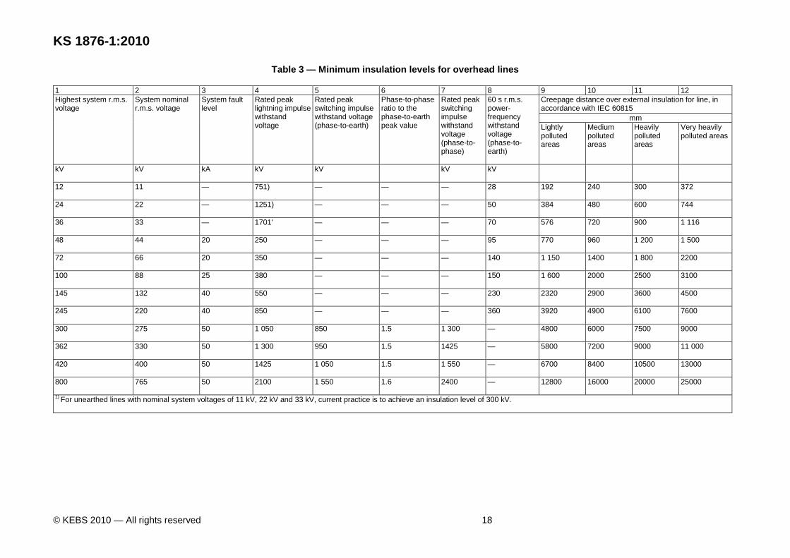
Minimum insulation levels are given in Table 3, but it is emphasized that the insulation of each line should be designed for its specific conditions. The list of insulation levels is in accordance with IEC 60071-1 and IEC 60071-2. There is a slight deviation on the 66 kV and 330 kV levels, where slightly higher lightning and switching voltage withstand levels were selected, based on specific experience of South African lightning conditions.
NOTE The designed line insulation levels will determine line equipment clearances. The minimum safety phase-to-earth clearances shown in column 3 of Table C.1 of Annex C should not be interpreted as specifying line equipment clearances.
In the range of rated voltage that is within the scope of this standard, there are three ranges with distinctive insulation criteria and therefore insulation levels. They are given in 6.6.2.1 to 6.6.2.3. 6.6.2.1 Range A, for line voltages less than 52 kV
The main criterion is only the lightning impulse overvoltages, which can be severe when the load is disconnected on the low-voltage winding of a transformer connected to a transmission line. This impulse voltage is usually reduced by the use of surge arresters.
Draf
t Ken
ya S
tand
ard
for B
allot
ing —
Not
to b
e Ci
ted
as K
enya
Sta
ndar
d
KS 1876-1:2010
16 © KEBS 2010 — All rights reserved
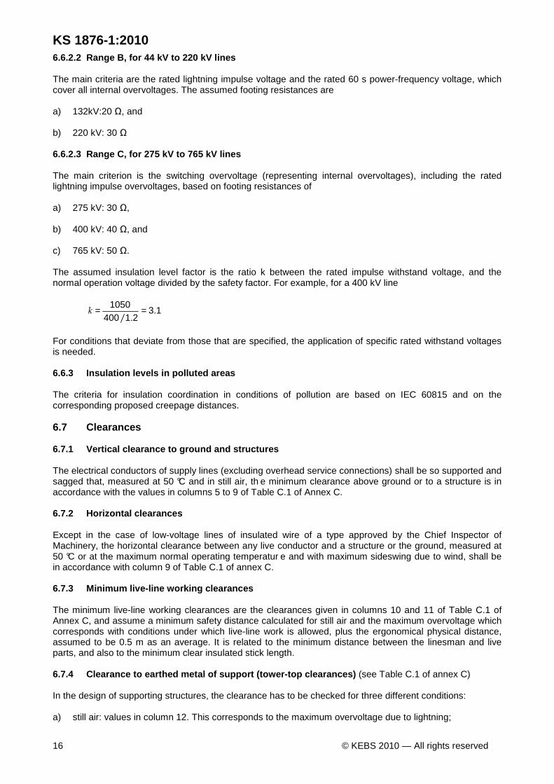
6.6.2.2 Range B, for 44 kV to 220 kV lines The main criteria are the rated lightning impulse voltage and the rated 60 s power-frequency voltage, which cover all internal overvoltages. The assumed footing resistances are a) 132kV:20 Ω, and b) 220 kV: 30 Ω 6.6.2.3 Range C, for 275 kV to 765 kV lines The main criterion is the switching overvoltage (representing internal overvoltages), including the rated lightning impulse overvoltages, based on footing resistances of a) 275 kV: 30 Ω, b) 400 kV: 40 Ω, and c) 765 kV: 50 Ω. The assumed insulation level factor is the ratio k between the rated impulse withstand voltage, and the normal operation voltage divided by the safety factor. For example, for a 400 kV line
1321400
1050.
./==k
For conditions that deviate from those that are specified, the application of specific rated withstand voltages is needed. 6.6.3 Insulation levels in polluted areas The criteria for insulation coordination in conditions of pollution are based on IEC 60815 and on the corresponding proposed creepage distances. 6.7 Clearances 6.7.1 Vertical clearance to ground and structures The electrical conductors of supply lines (excluding overhead service connections) shall be so supported and sagged that, measured at 50 °C and in still air, th e minimum clearance above ground or to a structure is in accordance with the values in columns 5 to 9 of Table C.1 of Annex C. 6.7.2 Horizontal clearances Except in the case of low-voltage lines of insulated wire of a type approved by the Chief Inspector of Machinery, the horizontal clearance between any live conductor and a structure or the ground, measured at 50 °C or at the maximum normal operating temperatur e and with maximum sideswing due to wind, shall be in accordance with column 9 of Table C.1 of annex C. 6.7.3 Minimum live-line working clearances The minimum live-line working clearances are the clearances given in columns 10 and 11 of Table C.1 of Annex C, and assume a minimum safety distance calculated for still air and the maximum overvoltage which corresponds with conditions under which live-line work is allowed, plus the ergonomical physical distance, assumed to be 0.5 m as an average. It is related to the minimum distance between the linesman and live parts, and also to the minimum clear insulated stick length. 6.7.4 Clearance to earthed metal of support (tower- top clearances) (see Table C.1 of annex C) In the design of supporting structures, the clearance has to be checked for three different conditions: a) still air: values in column 12. This corresponds to the maximum overvoltage due to lightning;
Draf
t Ken
ya S
tand
ard
for B
allot
ing —
Not
to b
e Ci
ted
as K
enya
Sta
ndar
d
KS 1876-1:2010
© KEBS 2010 — All rights reserved 17
b) normal (average) swing: values in column 13. This corresponds to the maximum switching over-voltage;
and c) maximum swing: values in column 14: This corresponds to the maximum normal operating voltages. In the case of an insulator string that is not movable perpendicular to the line direction (V-string, post-insulators), only clearances for still air conditions are relevant. In the case of overvoltages that differ significantly from the values for which rated insulation levels were established (see Table 3), or of different coincidences of overvoltages on the line and wind velocity, equivalent clearances have to be calculated for all three conditions, using as a basis the safety clearance values from column 3 of Table C.1 of annex C. (See also clause C.1 of Annex C.) Over reasonably level terrain, the swing angle of a suspension insulator string is likely to exceed 50° to the vertical, and care shall be taken to ensure that vertical clearances to cross-arms and also horizontal clearances to the body of the structure are maintained. The use of alloy conductors will lead to larger swing angles than the equivalent ASCR conductors under the same conditions. Also, the smaller the diameter of the conductor used, the more likely that the swing angle will exceed 50°. Structures that support litt le vertical load, for example in a valley, will have larger swings and might need to be replaced by strain structures. The swing angle of a jumper will vary with the length, mass and diameter of the conductor, and clearances shall be checked for the maximum swing. Long jumpers might require the use of intermediate insulators or stiffeners to avoid the risk of their swinging too close to the structure metalwork.
Draf
t Ken
ya S
tand
ard
for B
allot
ing —
Not
to b
e Ci
ted
as K
enya
Sta
ndar
d
KS 1876-1:2010
© KEBS 2010 — All rights reserved 18
Table 3 — Minimum insulation levels for overhead li nes
1 2 3 4 5 6 7 8 9 10 11 12 Highest system r.m.s. voltage
System nominal r.m.s. voltage
System fault level
Rated peak lightning impulse withstand voltage
Rated peak switching impulse withstand voltage (phase-to-earth)
Phase-to-phase ratio to the phase-to-earth peak value
Rated peak switching impulse withstand voltage (phase-to-phase)
60 s r.m.s. power-frequency withstand voltage (phase-to-earth)
Creepage distance over external insulation for line, in accordance with IEC 60815
mm Lightly polluted areas
Medium polluted areas
Heavily polluted areas
Very heavily polluted areas
kV kV kA kV kV kV kV
12
11
— 751)
— — — 28
192
240
300
372
24
22
— 1251)
— — — 50
384
480
600
744
36
33
— 1701'
— — — 70
576
720
900
1 116
48
44
20
250
— — — 95
770
960
1 200
1 500
72
66
20
350
— — — 140
1 150
1400
1 800
2200
100
88
25
380
— — — 150
1 600
2000
2500
3100
145
132
40
550
— — — 230
2320
2900
3600
4500
245
220
40
850
— — — 360
3920
4900
6100
7600
300
275
50
1 050
850
1.5
1 300
— 4800
6000
7500
9000
362
330
50
1 300
950
1.5
1425
— 5800
7200
9000
11 000
420
400
50
1425
1 050
1.5
1 550
— 6700
8400
10500
13000
800
765
50
2100
1 550
1.6
2400
— 12800
16000
20000
25000
1) For unearthed lines with nominal system voltages of 11 kV, 22 kV and 33 kV, current practice is to achieve an insulation level of 300 kV.

Draf
t Ken
ya S
tand
ard
for B
allot
ing —
Not
to b
e Ci
ted
as K
enya
Sta
ndar
d
KS 1876-1:2010
© KEBS 2010 — All rights reserved 19
6.7.5 Clearance between phase conductors To allow for a certain amount of out-of-phase swinging of phase conductors, it is usual to allow clearances that exceed the values given in column 4 of Table C.1 of Annex C, between conductors of different phases of a transmission line. The allowance made is based on experience, and many empirical formulae have been used in this respect by various authorities. All methods are based on the same general principle, that the spacing, in metres, is given by:
Dd + Cc where
Dd is the differential conductor displacement, in metres, which depends on the wind characteristics, the span length and the conductor characteristics; and
Cc is the phase-to-phase clearance, in metres, which depends on the conditions on which the
calculations are based. This can be the clearance for the maximum expected overvoltage (see column 9 of Table C.1 of Annex C), or the phase-to-phase clearance for the normal operating voltage.
A more sensitive approach needs to assume, in the calculation of incremental movement, the sag of the conductor (or tension), the length of the suspension string and the actual position between conductors in the span. A simple formula for the spacing, in metres, which can be used to determine a reasonable horizontal spacing between phase conductors of lines in a flat configuration and with the tensions recommended in 5.2, is:
5L + C where
L is the span length, in kilometres; and C is the phase-to-phase clearance, in metres, as given in column 4 of Table C.1 of Annex C.
In the case of lines with vertical configuration and with triangular configuration, the required spacing depends on the configuration but would normally be less than 5L + C, owing to conductors' not being in the same horizontal plane. In the vertical plane, conductor spacing shall take into account movement of conductors during fault conditions, and could therefore exceed the phase-to-phase clearance. 6.8 Stay wires 6.8.1 Purpose of stays If a line is designed to have structures supported by stay wires, the stay wires are used to relieve the structure of the horizontal loading that is imposed by the tension in the conductors and earth wires. Loads due to conductor and earth wire tension can arise from normal loading (see 6.2.6 and 6.2.7), or from broken conductors (see 6.3), or can be caused by erection loading (see 6.4). 6.8.2 Strength of stays 6.8.2.1 Factor of safety The applicable safety factors shall be used. The strength of any stay wire used should be such that its ultimate tensile strength is at least 2.5 times the maximum tension calculated as indicated in 6.2.6 for normal conditions.
Draf
t Ken
ya S
tand
ard
for B
allot
ing —
Not
to b
e Ci
ted
as K
enya
Sta
ndar
d
KS 1876-1:2010
20 © KEBS 2010 — All rights reserved
6.8.2.2 Broken conductors If stay wires are used to withstand loading due to a broken conductor or to erection conditions, the factor of safety may be reduced, but the ultimate strength should be at least 1.5 times the maximum tensile force calculated as indicated in 6.2.6 for the appropriate condition. 6.8.2.3 Stay rods Higher factors of safety should be used for stay rods than for stay wires, especially where threaded portions are in tension. A factor of safety of 2.5 should be used for stay rods and one of at least 3 for their threaded portions. 6.8.3 Location of stays Wherever practicable, a stay should be attached to the structure at the point of application of the load which it is designed to counteract and should extend in a direction opposite to that of this load. The location should be such that the clearance from the stay wire to any live parts of the line under all design conditions is not less than the appropriate phase-to-earth clearance given in Annex C. Wherever practicable, stay wires should not pass under, over or near communication lines or the associated poles. Where this is unavoidable, stays should be installed in such a way that linesmen working on the poles or wires of the communication line cannot come closer than the appropriate phase-to-earth clearance to any portion of the stay that could become alive under fault conditions. 6.8.4 Stay guards As stays are vulnerable to mechanical damage and can constitute a danger to pedestrian and vehicular traffic, all stays near public paths and roadways should be fitted with stay guards. The stay guards should enclose the stay wire from the top of the stay rod or bow to a point 2 m above the ground, should be of width at least 50 mm and should be so coloured as to be conspicuous by day and by night. 6.8.5 Stay insulation It is advisable to include insulation in the stay where the introduction of a stay will affect the BIL (see 3.1) of a structure. If a standard stay insulator would not provide adequate BIL, an insulated rod shall be used. 7 Crossings 7.1 Crossings over roads, railways, tramways and co mmunication lines If the crossing span is strained off at each end, the crossing would not be affected by damage to the conductors beyond the crossing. It is, therefore, unnecessary to fit arcing horns or armour rods to the live end of insulators on strain or intermediate structures beyond the crossing span. In the crossing span itself, however, arcing horns are required where the conductor would be damaged in the event of a flashover. Conventional armour rods shall not be used where the conductor is secured to a rigid insulator by means of a preformed tie, because in the event of a breakage, the conductor can slide through the ungritted armour rods and the crossing span clearance would consequently be reduced to below the minimum of 4.5 m. To overcome this problem, a full-wrap preformed twin tie should be used, which, in addition to fixing the conductor securely to the rigid insulator, also protects the conductor against damage in the event of flashover. 7.2 Crossings over water No specific statutory requirements exist for crossings over water and, in general, normal ground clearances should be provided. However, where such crossings are made over rivers, dams or lakes, which are, or could be, used as recognized sailing waters, it is recommended that a clearance of 2.5 m plus the relevant minimum outdoor clearance (see Annex C) be provided over the tallest boat mast likely to be encountered on such water under conditions of normal high-water level and maximum conductor sag.
Draf
t Ken
ya S
tand
ard
for B
allot
ing —
Not
to b
e Ci
ted
as K
enya
Sta
ndar
d
KS 1876-1:2010
© KEBS 2010 — All rights reserved 21
The tallest boat mast to be encountered on inland waters is not likely to exceed 15.5 m. Checks should, however, be carried out for the particular stretches of waters that are to be crossed. 7.3 Joints in crossings It is recommended that no joints be made in either the conductors or the earth wires of a crossing span at the time of erection. 7.4 Crossings over other services Crossings over other services shall be in accordance with responses to the submissions required by Clause 9. 8 Earthing 8.1 Support structures for power lines Statutory regulations require that all metal power line structures and any metalwork on wooden or concrete structures that could accidentally become alive and is accessible, i.e. within 2.4 m of the ground, be earthed. This requirement is satisfied by metal structures that have steel grillage foundations, since the structure is connected to earth through its own metal legs. In the case of steel structures on concrete foundations, it is usual practice to bond the structure to buried earth conductors. The effectiveness of the earthing of a structure can be determined by measuring its resistance to earth, using a suitable instrument. If this resistance is so high that the structure is not earthed (see 3.4), a supplementary earthing system should be provided. Guidance on the value of earth resistance required for footings is given in 6.6.2. In addition, in the case of terminal structures, a footing resistance of less than 10 Ω is recommended. Similarly, for the second, third and fourth structures from a substation, a footing resistance of less than 20 Ω is recommended. It is generally not practicable to provide a sufficiently low earth resistance to ensure that there will be no hazard to life in the event of a fault in a structure. The risk can, however, be reduced by the use of fast and reliable protection so that the dangerous condition exists for only a short time, i.e. that taken by the protective devices to interrupt the supply to the line. 8.2 Fittings Power line fittings that are more than 2.4 m above ground do not have to be earthed. If the ends of insulator assemblies attached to cross-arms of non-conducting material are not earthed or if metal cross-arms mounted on structures of non-conducting material are not earthed, the line will have maximum insulation to earth and therefore the best performance against flashovers caused by overvoltages. On the other hand, if contamination or puncture of line insulation permits the flow of heavy leakage currents over wooden cross-arms or poles, these cross-arms or poles can become charred and can eventually fail. 8.3 Earth wires 8.3.1 Purpose Earth wires are provided on power lines to reduce the number of outages caused by lightning, and to provide a return path for earth fault currents. 8.3.2 Position To reduce the number of outages caused by lightning, earth wires should be located above the phase conductors in such a position that the cover angle, i.e. the angle to the vertical from a line joining the earth wire and the phase conductor, is reasonably small.
Draf
t Ken
ya S
tand
ard
for B
allot
ing —
Not
to b
e Ci
ted
as K
enya
Sta
ndar
d
KS 1876-1:2010
22 © KEBS 2010 — All rights reserved
On the other hand, the height of the earth wire above ground should be as low as possible, to minimize the number of lightning strokes that will strike the line. The lightning strokes can appear anywhere along the line. However, the metal structures tend to attract a greater proportion of strokes because they are higher. The midspan attracts a lower proportion of strokes because it is closer to earth. In the case of metal support structures, 60 % of strokes to the line can be considered as terminating on the structure. Insulated support structures attract fewer lightning strokes. In this case, only 40 % of strokes terminate on the structure. In the case of a single earth wire, a low cover angle can only be achieved by so increasing the height of the earth wire that the best position represents a compromise that gives an acceptable cover angle but keeps the earth wire reasonably low. Cover angles in the range 30° to 45° are commonly u sed in the case of single earth wire systems. The higher value is associated with low lightning activity, structure heights below the range of 25 m to 30 m and less important power lines. If two earth wires are used, they can be located to give low cover angles to the outer conductors of the line by spreading the earth wires apart instead of raising them vertically. It is therefore common practice, when two earth wires are used, to provide the outer conductors with cover angles of 30° or less, the height of the earth wire s being as low as possible, consistent with giving good protection, say 60° cover angle, to the conductors between the earth wires. If earth wires are only used to provide a return path for earth fault currents, they should preferably be located below the line conductors so that, if a conductor breaks, there is a possibility that it will make contact with the earth wire. 8.3.3 Earthing of earth wires The voltage imposed by a lightning stroke on an earth wire will rise rapidly to a value such that flashover will occur from the earth wire to the phase conductors close to the point where the lightning strikes, unless the lightning current is by-passed to earth through a low impedance. The lightning protection that is provided by an earth wire therefore depends on how well and how frequently the wire is earthed. For this reason, earth wires installed as lightning protection should be connected to earth at each power line support, either through the support in the case of metal supports, or by an earthing conductor in the case of supports of non-conducting materials. To avoid flashover across the line insulation in a structure owing to the high voltage on the earth wire, the resistance to earth should be as low as possible. In the case of a 22 kV line with the insulator assemblies earthed at the point of attachment to the cross-arms, flashovers across the line insulators might be expected for
a) 50 % of the lightning strokes that terminate on the earth wire when the resistance to earth is 10 Ω
b) 80 % when the resistance to earth is 20 Ω and
c) 98 % (or virtually all strokes) when the resistance to earth is 50 Ω.
Since it is often difficult to attain an earth resistance of less than 50 Ω earth wires are seldom economically justified to improve the lightning performance of lines that operate at 22 kV or at lower voltages.
Where wooden poles are used as supports on lines that operate below 33 kV, lightning protection can generally be improved by omitting earth wires and leaving the insulator assemblies unearthed, thus keeping the insulation level as high as possible. This form of construction has the disadvantage that a direct stroke to a pole can cause it to shatter, but the probability of this happening is reasonably low.
Earth wire insulators that comply with IEC 60383-1 and that are fitted with a spark gap set to 6 mm shall be installed in the following circumstances:
a) at terminal structures not connected to the main substation earth mat;
Draf
t Ken
ya S
tand
ard
for B
allot
ing —
Not
to b
e Ci
ted
as K
enya
Sta
ndar
d
KS 1876-1:2010
© KEBS 2010 — All rights reserved 23
b) at traction substation terminal structures;
c) on the second, third, fourth and fifth structures from the substation if any or all of these structures have footing resistances of less than 10 Ω; and
d) at all structures within 800 m of electrified railway tracks or metal pipelines where the power line either crosses, or runs parallel to, the railway or pipeline.
9 Procedure to be adopted before the construction o f power lines 9.1 General Attention is drawn to the necessity of notifying the appropriate authorities in accordance with statutory requirements (see Annex A) before starting the construction of any new power line or an extension of any existing line. The procedure to be adopted will vary according to the line route conditions and will necessitate the submission of a written notification to one or more of the authorities given in 9.3 to 9.9 (inclusive). 9.2 Environmental impact Cognizance should be taken of the Environmental Management Coordination Act, EMCA, 1998. 9.3 Telecommunications authority In every case, and not less than one month before any construction is started, the owner of a proposed power line shall submit a written notification, in duplicate, to the telecommunications authority, giving the following particulars of the proposal: a) a map or plan indicating the position of the entire length of proposed power line in relation to
topographical features and its distance from existing communication lines, roads and railways;
b) the proposed operating voltage and, if a future change is contemplated, the ultimate operating voltage between conductors;
c) a sketch showing the typical arrangement of the line conductors and earth wires and their heights above ground;
d) the location of any power line transpositions;
e) the location of any taps off the power line;
f) the maximum time for an earth fault to be cleared;
g) the maximum current in the event of an earth fault;
h) the maximum operating current of the route; and i) the type of earth conductor used on the route. 9.4 Appropriate road authority When the proposed power line is to be constructed over, or within the reserve of, a public road, permission shall be sought from the appropriate road authority. 9.5 Civil Aviation Authority It is necessary that proposals for the construction of any power line be submitted to the Civil Aviation Authority, to ensure that the provisions of the Aviation Act are met. This is necessary to avoid creating obstructions in the vicinity of existing or proposed aerodromes or airports. 9.6 Other electricity supply authorities
If the proposed power line is to be constructed over, or within the servitude of, another electricity supply authority, the permission of that authority shall be sought, and the safety clearances adhered to.
Draf
t Ken
ya S
tand
ard
for B
allot
ing —
Not
to b
e Ci
ted
as K
enya
Sta
ndar
d
KS 1876-1:2010
24 © KEBS 2010 — All rights reserved
Annex A
(normative)
Principal Acts, ordinances, regulations and instruc tions pertaining to overhead power lines
The Advertising on Roads and Ribbon Development Act, 1940 (Act 21 of 1940). The Air Navigation Regulations issued in terms of the Aviation Act, 1962 (Act 74 of 1962). The Electricity Act, 1987 (Act 41 of 1987). The Environment Conservation Act, 1989 (Act 73 of 1989). The Explosives Act, 1956 (Act 26 of 1956). The Fencing Act, 1963 (Act 31 of 1963). The Forest Act, 1984 (Act 122 of 1984). The Minerals Act, 1991 (Act 50 of 1991), and subsequent amendments and regulations issued thereunder. The Occupational Health and Safety Act, 1993 (Act 85 of 1993), and subsequent amendments and regulations issued thereunder. The Post Office Act, 1958 (Act 44 of 1958), and the Postmaster-General's regulations issued in terms of that Act. Highway Commission; Road Ordinance.
Draf
t Ken
ya S
tand
ard
for B
allot
ing —
Not
to b
e Ci
ted
as K
enya
Sta
ndar
d
KS 1876-1:2010
© KEBS 2010 — All rights reserved 25
Annex B
(normative)
Guidance on power lines and communication circuits B.1 General This guidance has been prepared to provide authorities with sufficient information to enable them to conduct a survey that will enable the suitable positioning of power lines in relation to overhead communication circuits, having regard to noise interference in the latter circuits. B.2 Approval of the Telecommunications Authority The erection of a power line in conformity with this guide does not imply the automatic approval of the Telecommunications Authority. It is essential that the supply authority submit details of all power proposals in terms of the relevant Act. B.3 Co-ordination of transpositions While it is desirable to co-ordinate overhead communication line transpositions with power line transpositions, or other discontinuities in the power line, in practice, irregular or slanting exposures make such co-ordination difficult or of little value. Experience has shown that, provided that a communication line is frequently transposed, the co-ordination of transpositions is of secondary importance. However, it is required that the supply authority indicate all proposed power line transpositions on the plan of the proposed power line when submitting it for approval. B.4 Minimum separating distances The minimum horizontal separating distances between power lines and communication lines shall be determined from the curves given in figures B.1, B.2, B.3 and B.4. These curves have been based on considerations of the inductive and electrostatic interference with communication circuits. B.4.1 Maximum range of curves Since these curves apply to power line exposures not exceeding 48 km in length, the curves shall not be extrapolated. B.4.2 Several exposures in series In practice, it is generally found that topographical features at power line crossings over communication lines do not permit the exact minimum separating distances being maintained throughout the exposure. Where a particular power line and a particular communication line are involved in this way, the curves may be applied to each of the resulting exposures separately. The separating distances given by the curves should, wherever practicable, be increased by a factor of 1.5, or as near to this as possible, to cater for the additive effect of several exposures in series. B.4.3 Telephone interference factors (TIP) In the case of power line voltages up to and including 33 kV, a TIP of 10 % has been used. In the case of lines of a higher voltage, a TIP of 5 % has been adopted, since it is likely that interfering factors (such as phase balance, wave form, etc.) are more closely controlled on such lines. B.4.4 Psophometric noise The curves are based on the recommendations of the International Telecommunication Union (CCITT), namely that the noise induced in a communication circuit should not exceed 2 mV e.m.f. when the noise is measured with a psophometer fitted with the CCITT telephone weighting network. The 2 mV e.m.f. is equivalent to 1 mV potential difference, as measured on the psophometer.
Draf
t Ken
ya S
tand
ard
for B
allot
ing —
Not
to b
e Ci
ted
as K
enya
Sta
ndar
d
KS 1876-1:2010
26 © KEBS 2010 — All rights reserved
B.5 Ultimate terminal of power line route If, in submitting a power line proposal to the Telecommunications Authority for approval, the supply authority is aware that the power line might be extended beyond the immediate proposal at some future date, the probable ultimate terminal of the power line route should be indicated by the supply authority. B.6 Power line and communication line crossings The power line route should cross the communication line route as nearly as possible at right angles. Where this is impracticable, the following deviations from a right-angle crossing are permitted, provided that the terms of B.4.2 are observed:
Table B.1 — Maximum deviation angles on communicati on line crossings
1 2 Voltage of route Permissible deviation from right angle
Below 48 kV 48 kV and above
45° 30°
B.7 Power line faults Where power line faults are likely to cause acoustic shock of serious proportions, the supply authority concerned and the Telecommunications Authority should co-operate in providing preventive measures. B.8 Exposures exceeding 48 km in length Where the power line proposal involves exposures exceeding 48 km in length, the supply authority should refer the project to the Telecommunications Authority after a preliminary survey but before a detailed survey. It will then be possible to indicate the minimum separations with greater accuracy in each particular case. B.9 Radio receiving stations If power lines exceeding 44 kV have to be erected in the vicinity of radio receiving stations, the separation required between the power line and the radio receiving aerials is of the order of 1.5 km. This separation depends on several factors, and the appropriate authority (usually the Telecommunications Authority) will indicate, in the case of every proposal, what the separation should be.
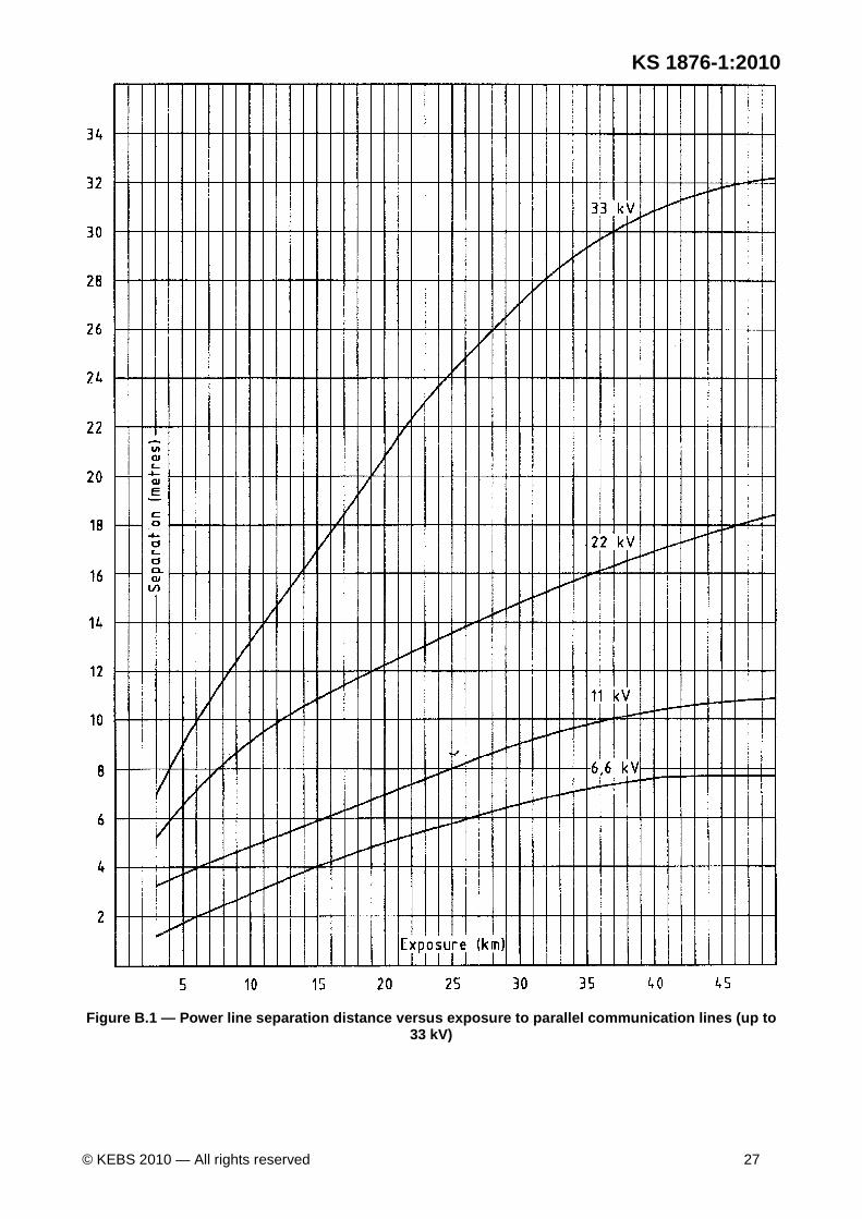
Draf
t Ken
ya S
tand
ard
for B
allot
ing —
Not
to b
e Ci
ted
as K
enya
Sta
ndar
d
KS 1876-1:2010
© KEBS 2010 — All rights reserved 27
Figure B.1 — Power line separation distance versus exposure to parallel communication lines (up to 33 kV)

Draf
t Ken
ya S
tand
ard
for B
allot
ing —
Not
to b
e Ci
ted
as K
enya
Sta
ndar
d
KS 1876-1:2010
28 © KEBS 2010 — All rights reserved
Figure B.2 — Power line separation distance versus exposure to parallel communication lines (from 44 kV to 132 kV)
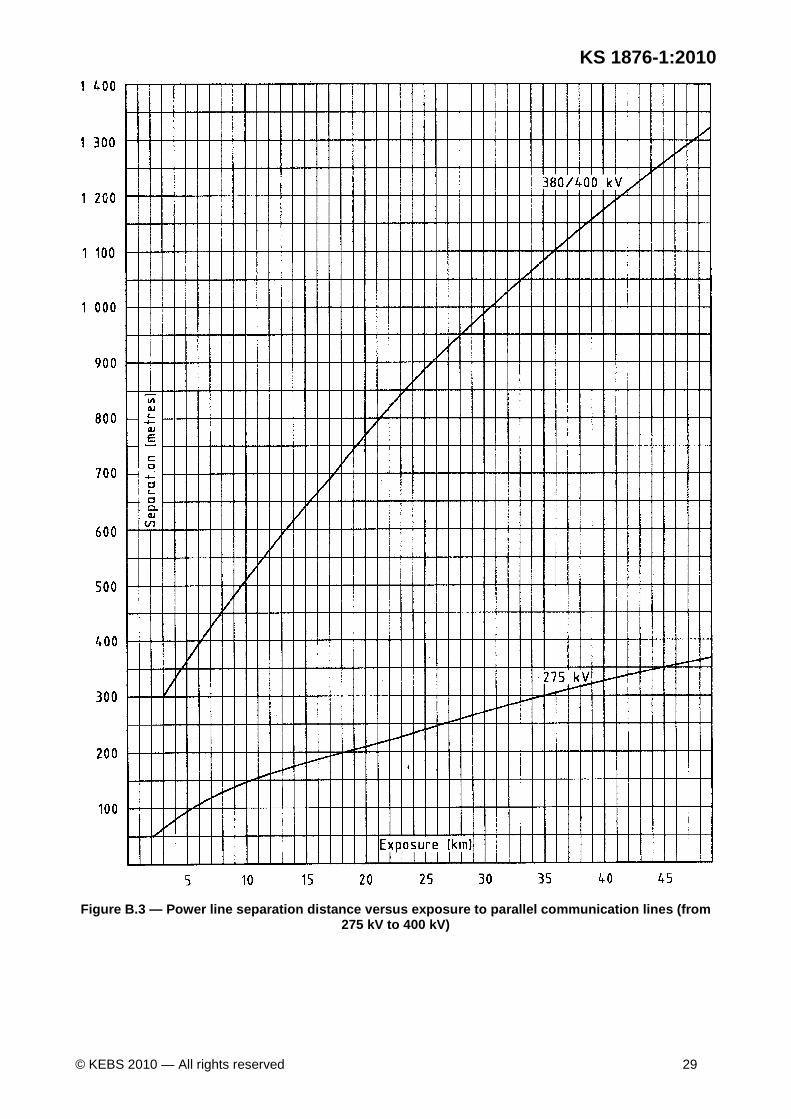
Draf
t Ken
ya S
tand
ard
for B
allot
ing —
Not
to b
e Ci
ted
as K
enya
Sta
ndar
d
KS 1876-1:2010
© KEBS 2010 — All rights reserved 29
Figure B.3 — Power line separation distance versus exposure to parallel communication lines (from 275 kV to 400 kV)
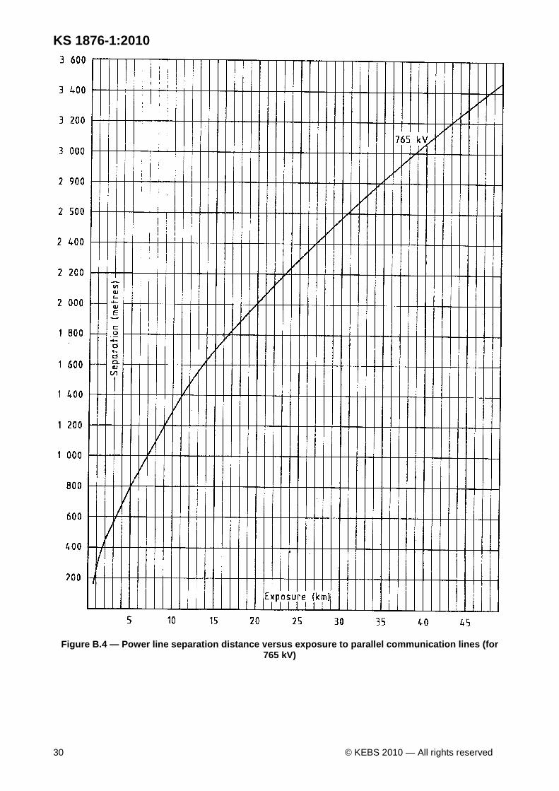
Draf
t Ken
ya S
tand
ard
for B
allot
ing —
Not
to b
e Ci
ted
as K
enya
Sta
ndar
d
KS 1876-1:2010
30 © KEBS 2010 — All rights reserved
Figure B.4 — Power line separation distance versus exposure to parallel communication lines (for 765 kV)