Embed Size (px)
Citation preview
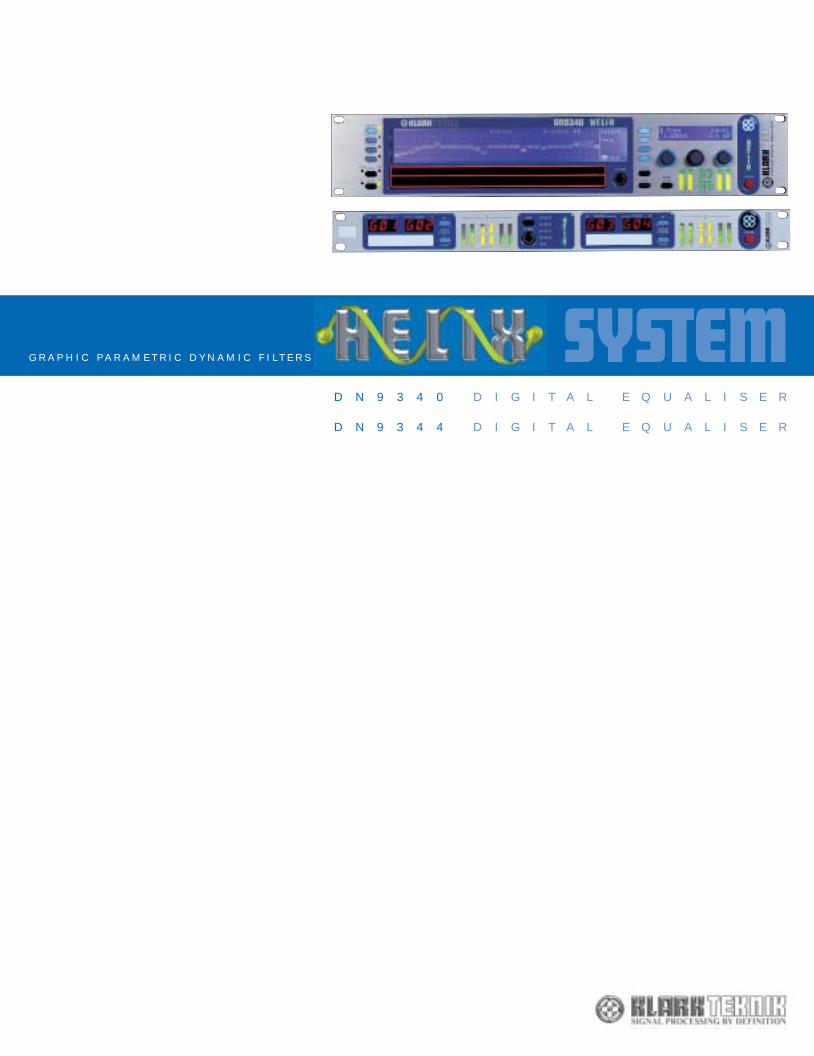
SYSTEMG R A P H I C P A R A M E T R I C D Y N A M I C F I L T E R S
D N 9 3 4 0 D I G I T A L E Q U A L I S E R
D N 9 3 4 4 D I G I T A L E Q U A L I S E RIn 1974, brothers Phil and Terry Clarke founded Klark Teknik Research Ltd. In the years immediatelyfollowing, their innovative approach to design and development allowed them to introduce some trulygroundbreaking designs. The world’s first digital delay and digital reverb units emanated from theirlaboratory, and their descendants remain in common usage all over the world to this day. However, it wastheir concepts for equalisation devices that really changed the world of professional audio. Their earliestdesigns eventually matured into the world famous DN360 that remains the industry standard graphic EQfor audio professionals everywhere.
Today, Klark Teknik continues to uphold the original vision of the Clarke brothers: innovation in design,followed by uncompromising dedication to engineering and sonic quality. Most of our units are still madeand tested by hand, a time consuming and labour intensive process that remains the only method bywhich we can maintain the quality that our customers expect. Uniquely in its field, Klark Teknik also providesthe customer with an opportunity to invest in leading-edge equipment with an extraordinary workinglifespan and unrivalled retained value. Global support for our products is readily available from the factoryin Kidderminster, from our international distributor network and via the Klark Teknik website.
Klark Teknik Group, Walter Nash Road, Kidderminster, Worcestershire, DY11 7HJ. England.Tel: +44 1562 741515 Fax: +44 1562 745371email: [email protected] www.klarkteknik.com
KT helix brochure plan 3/3/03 8:35 am Page 1
Inputs FourType Electronically balanced (pin 2 hot)Impedance (Ohm) 20kCommon Mode >80dB @ 1 kHzRejection
Outputs FourType Electronically balanced (pin 2 hot)Maximum Level +21dBu into >2k
PerformanceFrequency response 0.3 dB with all filters and EQ flat(20Hz to 20kHz)Distortion (THD+N) @ +4dBu <0.01%(20Hz to 20 kHz)Dynamic range 115 dB(20Hz-20kHz unweighted)
Processing (Per Channel)Input Gain +12dB to -40dB in 0.1dB steps plus OffDelay 0-1 second
(342.25 m or 333'10” at 20C in 20.8us steps)Filters 4 Filters (max)Types Low Pass, High Pass, Low Shelf, High Shelf, NotchDynamic EQ 2 Bands (max)Range ±12dBResponses Proportional, Constant, SymmetricalParametric EQ 12 Bands (max)Range ±12dBResponses Proportional, Constant, SymmetricalGraphic EQ 31 Bands On ISO standard frequenciesRange ±12dBResponses Proportional, Constant, Symmetrical, DN27, DN360
Power RequirementsVoltage 90 V to 250 V a.c. 50/60 HzConsumption <40VA
TerminationsAudio inputs/outputs 3-pin XLRRS-485 inputs/outputs 3-pin XLRRS-232 8-pin Mini-DIN socket (front)Relay Socket 9-pin D-type (rear)Power 3-pin IEC
DimensionsWidth 483 mm (19 inch)Height 44 mm (1.75 inch) 1RU HighDepth 287 mm (12 inch)
WeightNett 4kgShipping 6kg
technical specifications
DN9344Digital Equaliser slave unit
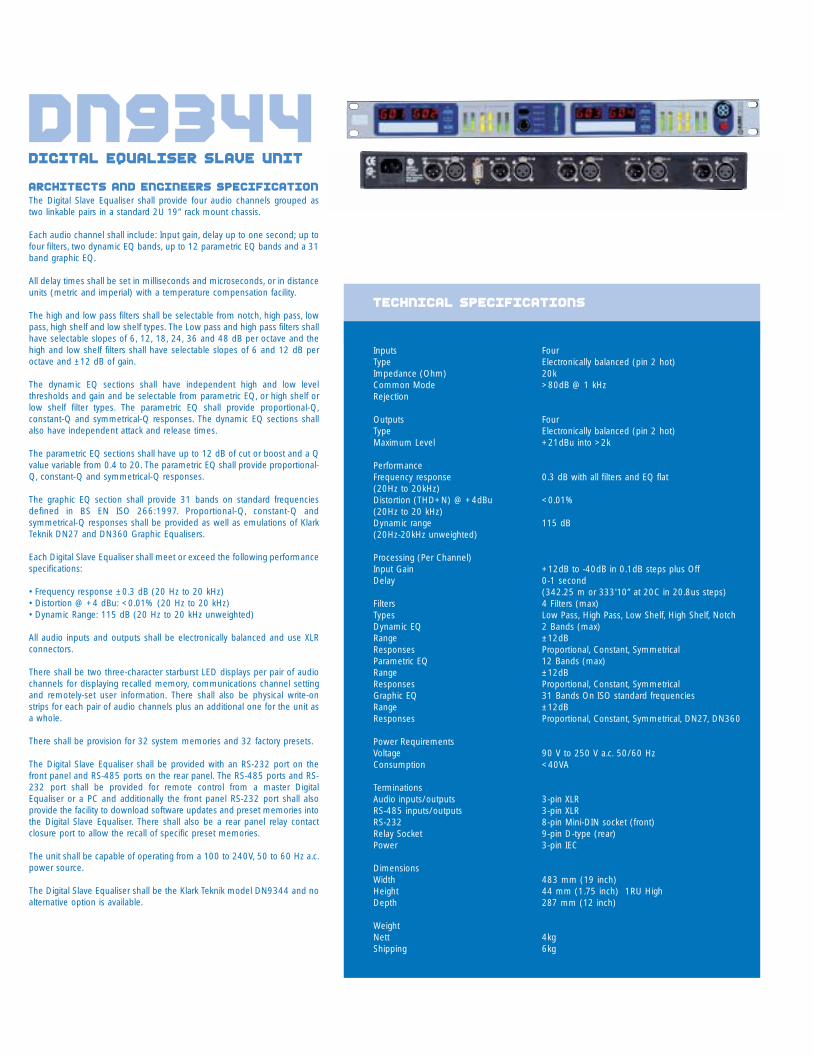
Architects and Engineers SpecificationThe Digital Slave Equaliser shall provide four audio channels grouped astwo linkable pairs in a standard 2U 19” rack mount chassis.
Each audio channel shall include: Input gain, delay up to one second; up tofour filters, two dynamic EQ bands, up to 12 parametric EQ bands and a 31band graphic EQ.
All delay times shall be set in milliseconds and microseconds, or in distanceunits (metric and imperial) with a temperature compensation facility.
The high and low pass filters shall be selectable from notch, high pass, lowpass, high shelf and low shelf types. The Low pass and high pass filters shallhave selectable slopes of 6, 12, 18, 24, 36 and 48 dB per octave and thehigh and low shelf filters shall have selectable slopes of 6 and 12 dB peroctave and ±12 dB of gain.
The dynamic EQ sections shall have independent high and low levelthresholds and gain and be selectable from parametric EQ, or high shelf orlow shelf filter types. The parametric EQ shall provide proportional-Q,constant-Q and symmetrical-Q responses. The dynamic EQ sections shallalso have independent attack and release times.
The parametric EQ sections shall have up to 12 dB of cut or boost and a Qvalue variable from 0.4 to 20. The parametric EQ shall provide proportional-Q, constant-Q and symmetrical-Q responses.
The graphic EQ section shall provide 31 bands on standard frequenciesdefined in BS EN ISO 266:1997. Proportional-Q, constant-Q andsymmetrical-Q responses shall be provided as well as emulations of KlarkTeknik DN27 and DN360 Graphic Equalisers.
Each Digital Slave Equaliser shall meet or exceed the following performancespecifications:
• Frequency response ±0.3 dB (20 Hz to 20 kHz)• Distortion @ +4 dBu: <0.01% (20 Hz to 20 kHz)• Dynamic Range: 115 dB (20 Hz to 20 kHz unweighted)
All audio inputs and outputs shall be electronically balanced and use XLRconnectors.
There shall be two three-character starburst LED displays per pair of audiochannels for displaying recalled memory, communications channel settingand remotely-set user information. There shall also be physical write-onstrips for each pair of audio channels plus an additional one for the unit asa whole.
There shall be provision for 32 system memories and 32 factory presets.
The Digital Slave Equaliser shall be provided with an RS-232 port on thefront panel and RS-485 ports on the rear panel. The RS-485 ports and RS-232 port shall be provided for remote control from a master DigitalEqualiser or a PC and additionally the front panel RS-232 port shall alsoprovide the facility to download software updates and preset memories intothe Digital Slave Equaliser. There shall also be a rear panel relay contactclosure port to allow the recall of specific preset memories.
The unit shall be capable of operating from a 100 to 240V, 50 to 60 Hz a.c.power source.
The Digital Slave Equaliser shall be the Klark Teknik model DN9344 and noalternative option is available.
introductionThe new Klark Teknik Helix system provides an intuitive yet sophisticated and flexible audio equalisation systemin a very compact package. Its unique selection of functions allows EQ to be applied with total precision, usingthe types and combinations of filters that deal most effectively with a given situation. Like all Klark Teknik DSPdevices, Helix is equipped with more than enough computing power to allow all functions to be fully operativeat all times.
Helix also offers a specific advantage to owners of MIDAS Heritage and Legend consoles, in the form of an 'auto-solo' function which allows instant access to all the Helix functions allocated to that input or output.
The principal operational advantage of Helix is that it offers all the functionality of several standalone devices inone package, thus saving massively on both cost and rackspace. For instance, enough EQ for a 24-way monitormix plus two sidefills will fit into just EIGHT rackspaces (six DN9344 slaves and one DN9340 Master), at almostexactly the same cost as the same number of channels of top-class analogue graphic EQ.
Like all KT units it is engineered to the highest standards and carries the usual KT 5-year transferableinternational factory warranty.
DN9340
2 c
hannels, 31
bands 1
/3 O
ctave d
igital f
ilters i
n 5
different f
ilter e
mulations p
er c
hannel, 12
bands 2
0Hz-2
0kHz o
f p
aram
etric e
qualisation p
er c
hannel, 2 b
ands o
fthreshold d
ependent e
qualisation (T-D
EQ) per c
hannel, 4
first t
o e
ighth o
rder f
ilters p
er c
hannel, 1
second o
f d
elay p
er c
hannel
DN9344
4 c
hannels, 31
bands, 1/
3 O
ctave d
igital f
ilters i
n 5
different f
ilter e
mulations p
er c
hannel, 12
bands, 20Hz-2
0kHz o
f p
aram
etric e
qualisation p
er c
hannel, 2 b
ands o
fthreshold d
ependent e
qualisation (T-D
EQ) per c
hannel, 4
first t
o e
ighth o
rder f
ilters p
er c
hannel, 1
second o
f d
elay p
er c
hannel
9340 details 3
9344 details 3
functions 5
connections 7
remote control 7
t-deq dynamic eq 9
Q types 11
9340 technical data 13
9344 technical data 14
KT helix brochure plan 3/3/03 8:35 am Page 3
Architects and Engineers SpecificationThe Digital Equaliser shall provide two audio channels in a standard 2U 19”rack mount chassis.
Each audio channel shall include: Input gain, delay up to one second; up tofour filters, two dynamic EQ bands, up to 12 parametric EQ bands and a 31band graphic EQ.
All delay times shall be set in milliseconds and microseconds, or in distanceunits (metric and imperial) with a temperature compensation facility.
The high and low pass filters shall be selectable from notch, high pass, lowpass, high shelf and low shelf types. The Low pass and high pass filters shallhave selectable slopes of 6, 12, 18, 24, 36 and 48 dB per octave and thehigh and low shelf filters shall have selectable slopes of 6 and 12 dB peroctave and ±12 dB of gain.
The dynamic EQ sections shall have independent high and low levelthresholds and gain and be selectable from parametric EQ, or high shelf orlow shelf filter types. The parametric EQ shall provide proportional-Q,constant-Q and symmetrical-Q responses. The dynamic EQ sections shallalso have independent attack and release times.
The parametric EQ sections shall have up to 12 dB of cut or boost and a Qvalue variable from 0.4 to 20. The parametric EQ shall provide proportional-Q, constant-Q and symmetrical-Q responses.
The graphic EQ section shall provide 31 bands on standard frequenciesdefined in BS EN ISO 266:1997. Proportional-Q, constant-Q andsymmetrical-Q responses shall be provided as well as emulations of KlarkTeknik DN27 and DN360 Graphic Equalisers.
Each Digital Equaliser shall meet or exceed the following performancespecifications:
• Frequency response ±0.3 dB (20 Hz to 20 kHz)• Distortion @ +4 dBu: <0.01% (20 Hz to 20 kHz)• Dynamic Range: 115 dB (20 Hz to 20 kHz unweighted)
All audio inputs and outputs shall be electronically balanced and use XLRconnectors. A 480 x 64 graphic LCD shall be provided to display a graphicalrepresentation of the equaliser section responses. All parameters shall bedisplayed and adjusted via a 20 x 2 alphanumeric LCD display, three rotaryencoders and individual menu buttons for each equaliser section. A dualtouchstrip shall be provided for use with the graphic LCD to allow theselection of graphic EQ band and gain, and centre or corner frequency forfilters, and dynamic and parametric EQ. The graphic and alphanumericLCDs and the dual touchstrip shall have LED backlights.
There shall be provision for 32 system memories and 32 factory presetswith a security lock-out feature. There shall also be a security lock-outfeature that is enabled when the unit is under remote control.
The Digital Equaliser shall be provided with RS-232 ports on the front andrear panels and RS-485 ports on the rear panel. The RS-485 ports and frontpanel RS-232 port shall be provided for remote control from a masterDigital Equaliser or a PC and additionally the front panel RS-232 port shallalso provide the facility to download software updates and preset memoriesinto the Digital Equaliser. The rear panel RS-232 port shall be provided forremote control from Midas Heritage and Legend mixing consoles.
The unit shall be capable of operating from a 100 to 240V, 50 to 60 Hz a.c.power source.
The Digital Equaliser shall be the Klark Teknik model DN9340 and noalternative option is available.
DN9340Digital Equaliser Master unit
Inputs TwoType Electronically balanced (pin 2 hot)Impedance (Ohm) 20kCommon Mode >80dB @ 1 kHzRejection
Outputs TwoType Electronically balanced (pin 2 hot)Maximum Level +21dBu into >2k
PerformanceFrequency response 0.3 dB with all filters and EQ flat(20Hz to 20kHz)Distortion (THD+N) @ +4dBu <0.01%(20Hz to 20 kHz)Dynamic range 115 dB(20Hz-20kHz unweighted)
Processing (Per Channel)Input Gain +12dB to -40dB in 0.1dB steps plus OffDelay 0-1 second
(342.25 m or 333'10” at 20C in 20.8us steps)Filters 4 Filters (max)Types Low Pass, High Pass, Low Shelf, High Shelf, NotchDynamic EQ 2 Bands (max)Range ±12dBResponses Proportional, Constant, SymmetricalParametric EQ 12 Bands (max)Range ±12dBResponses Proportional, Constant, SymmetricalGraphic EQ 31 Bands On ISO standard frequenciesRange ±12dBResponses Proportional, Constant, Symmetrical, DN27, DN360
Power RequirementsVoltage 90 V to 250 V a.c. 50/60 HzConsumption <40VA
TerminationsAudio inputs/outputs 3-pin XLRRS-485 inputs/outputs 3-pin XLRRS-232 8-pin Mini-DIN socket (front)
9-pin D-type (rear)Power 3-pin IEC
DimensionsWidth 483 mm (19inch)Height 88 mm (3.5 inch) 2RU HighDepth 303 mm (12 inch)
WeightNet 6kgShipping 8kg
technical specifications
KT helix brochure plan 3/3/03 8:35 am Page 5
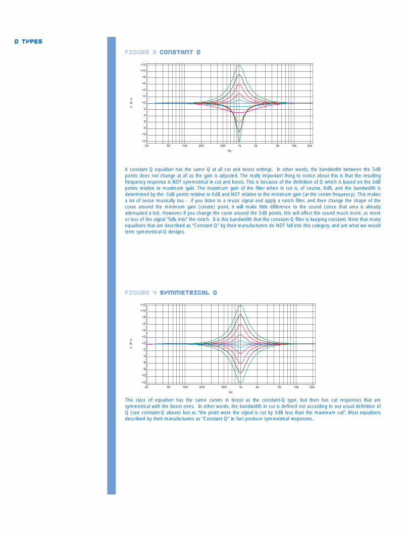
A constant Q equaliser has the same Q at all cut and boost settings. In other words, the bandwidth between the 3dBpoints does not change at all as the gain is adjusted. The really important thing to notice about this is that the resultingfrequency response is NOT symmetrical in cut and boost. This is because of the definition of Q which is based on the 3dBpoints relative to maximum gain. The maximum gain of the filter when in cut is, of course, 0dB, and the bandwidth isdetermined by the -3dB points relative to 0dB and NOT relative to the minimum gain (at the centre frequency). This makesa lot of sense musically too - if you listen to a music signal and apply a notch filter, and then change the shape of thecurve around the minimum gain (centre) point, it will make little difference to the sound (since that area is alreadyattenuated a lot). However, if you change the curve around the 3dB points, this will affect the sound much more, as moreor less of the signal “falls into” the notch. It is this bandwidth that the constant-Q filter is keeping constant. Note that manyequalisers that are described as “Constant Q” by their manufacturers do NOT fall into this category, and are what we wouldterm symmetrical-Q designs.
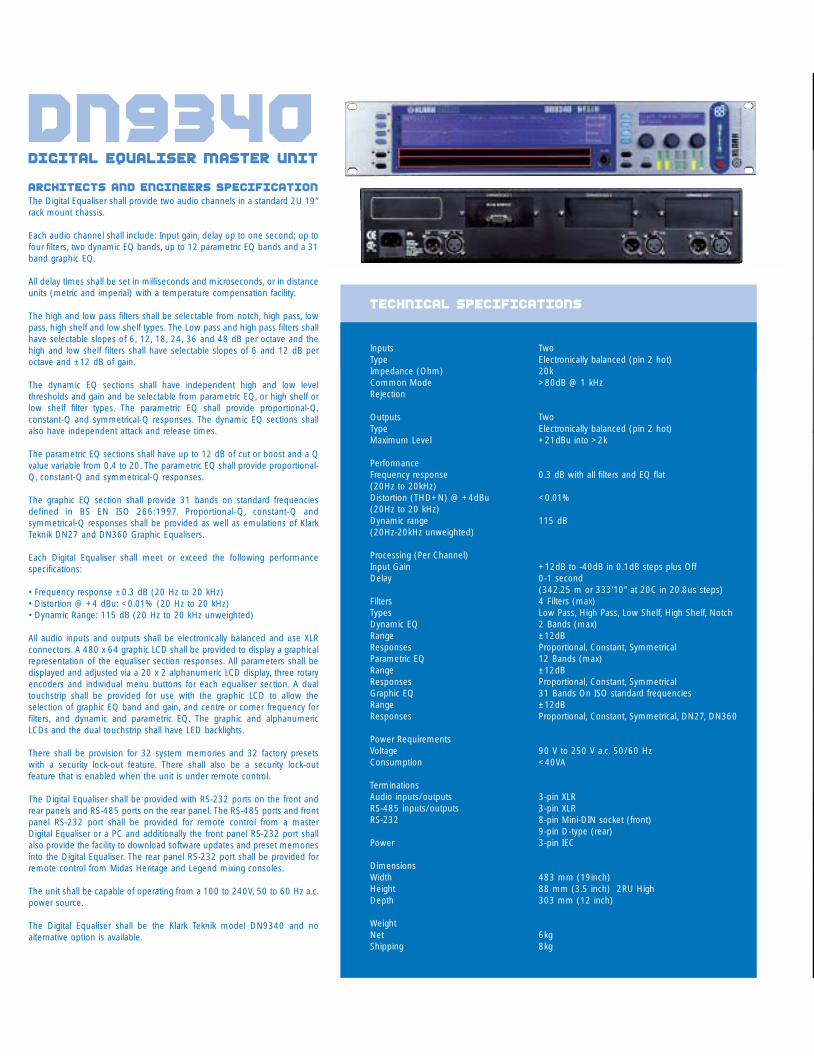
This class of equaliser has the same curves in boost as the constant-Q type, but then has cut responses that aresymmetrical with the boost ones. In other words, the bandwidth in cut is defined not according to our usual definition ofQ (see constant-Q above) but as “the point were the signal is cut by 3dB less than the maximum cut”. Most equalisersdescribed by their manufacturers as “Constant Q” in fact produce symmetrical responses..
Q types
figure 3 constant q
figure 4 Symmetrical q
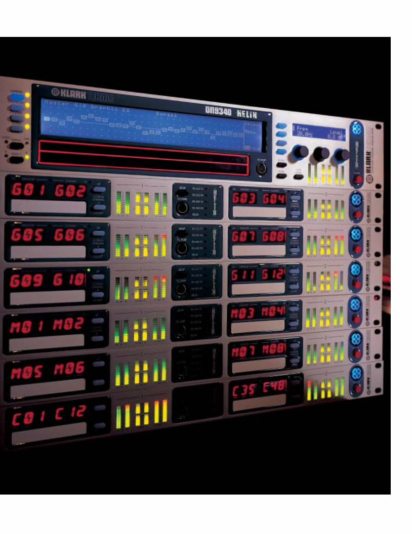
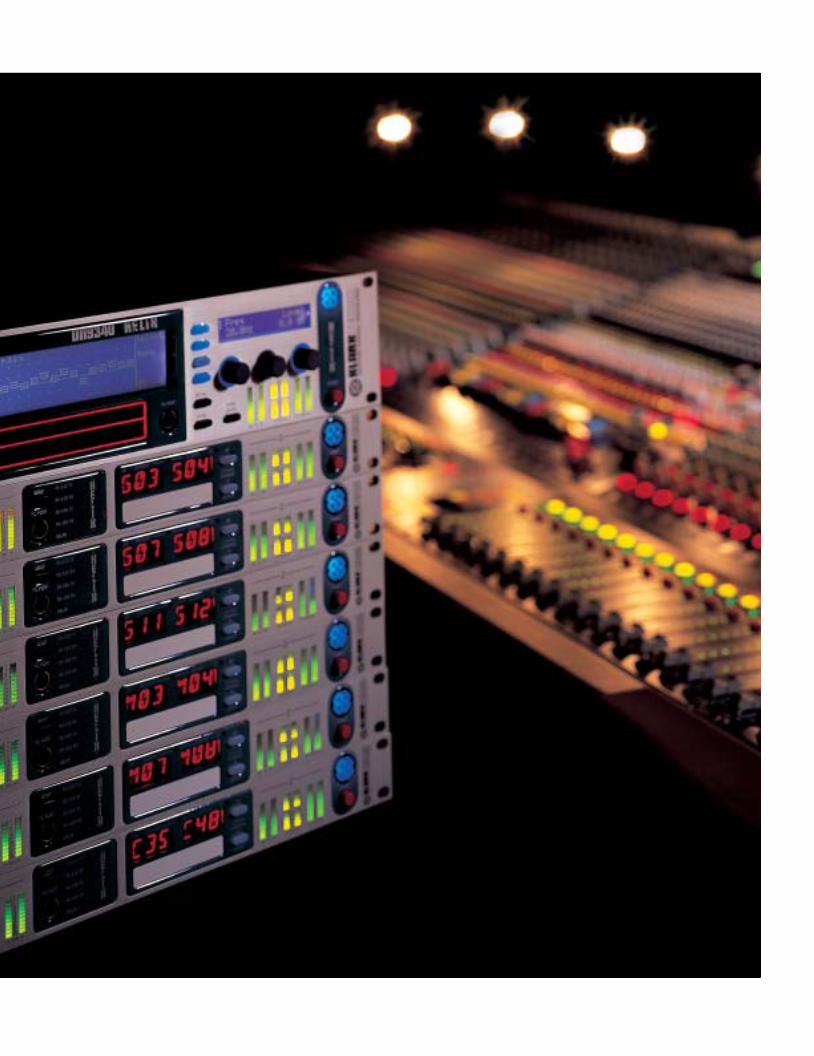
DN9340:THE MASTER unitThe Helix system comprises two units.The DN9340 Helix Master unit is a two-rackspace, dual channel device fitted witha simple and intuitive user interfaceincluding two backlit LED displays and fullmetering for inputs, outputs and T-DEQfilters. DN9340s may be used individuallyas stereo (linked-channel) units or asdual discrete channel units, and may beconfigured to control or be controlled byother Helix units. All functions includingmemory recall are available from the frontpanel, as well as high-speed selection ofindividual channels of any connectedHelix units.
DN9344:THE SLAVE unitThe DN9344 Helix Slave is a singlerackspace unit that effectively containstwo DN9340s in one chassis, thusproviding four channels. The pairs ofchannels can be linked for stereooperation or operated independently.DN9344 has no front panel controlsother than those that allow the user toselect communications channels, but it isfitted with the same comprehensivemetering as the Master unit. Specificallyfor installation purposes, the Helix Slave isalso fitted with a contact closure interfaceon the rear so that a limited number ofuser presets can be recalled from asimple switch panel without the need fora Helix Master unit or PC. The audio signalpath of the unit is identical in everyrespect to the Master.
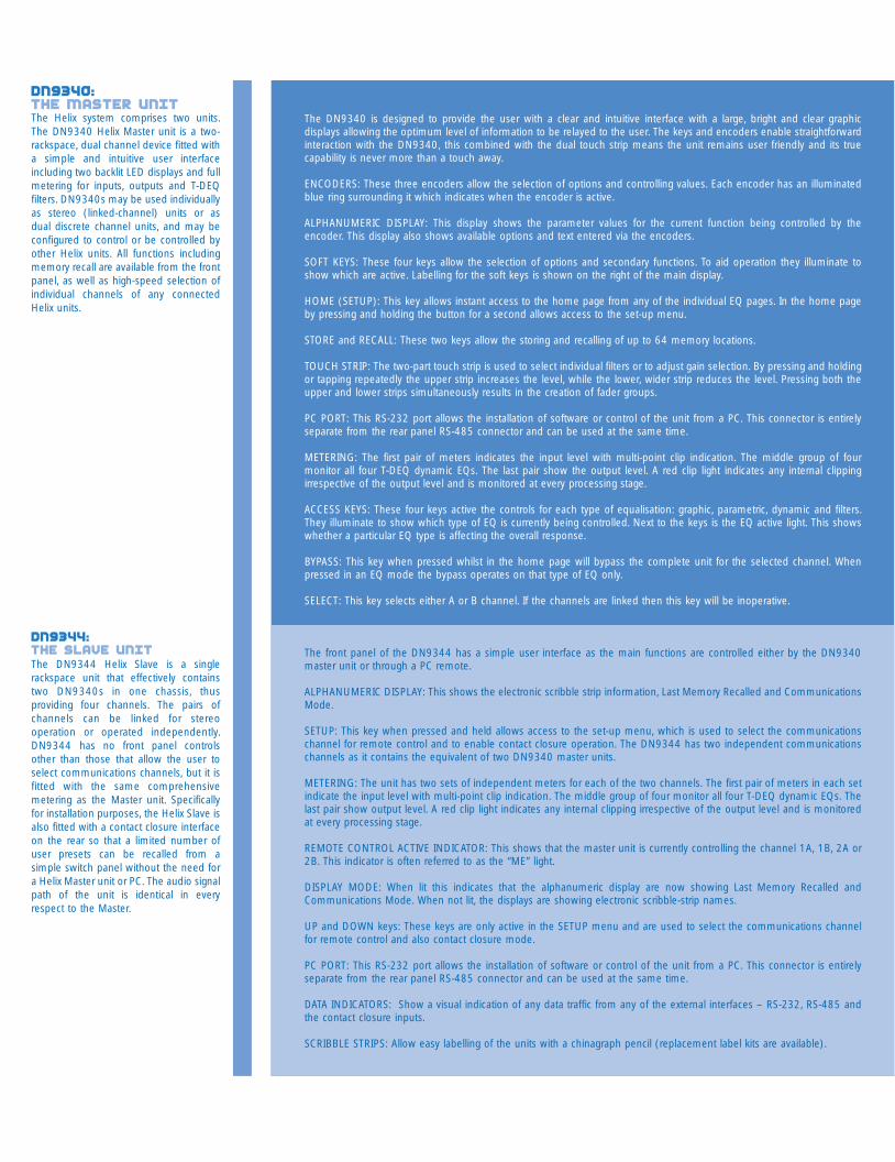
The DN9340 is designed to provide the user with a clear and intuitive interface with a large, bright and clear graphicdisplays allowing the optimum level of information to be relayed to the user. The keys and encoders enable straightforwardinteraction with the DN9340, this combined with the dual touch strip means the unit remains user friendly and its truecapability is never more than a touch away.
ENCODERS: These three encoders allow the selection of options and controlling values. Each encoder has an illuminatedblue ring surrounding it which indicates when the encoder is active.
ALPHANUMERIC DISPLAY: This display shows the parameter values for the current function being controlled by theencoder. This display also shows available options and text entered via the encoders.
SOFT KEYS: These four keys allow the selection of options and secondary functions. To aid operation they illuminate toshow which are active. Labelling for the soft keys is shown on the right of the main display.
HOME (SETUP): This key allows instant access to the home page from any of the individual EQ pages. In the home pageby pressing and holding the button for a second allows access to the set-up menu.
STORE and RECALL: These two keys allow the storing and recalling of up to 64 memory locations.
TOUCH STRIP: The two-part touch strip is used to select individual filters or to adjust gain selection. By pressing and holdingor tapping repeatedly the upper strip increases the level, while the lower, wider strip reduces the level. Pressing both theupper and lower strips simultaneously results in the creation of fader groups.
PC PORT: This RS-232 port allows the installation of software or control of the unit from a PC. This connector is entirelyseparate from the rear panel RS-485 connector and can be used at the same time.
METERING: The first pair of meters indicates the input level with multi-point clip indication. The middle group of fourmonitor all four T-DEQ dynamic EQs. The last pair show the output level. A red clip light indicates any internal clippingirrespective of the output level and is monitored at every processing stage.
ACCESS KEYS: These four keys active the controls for each type of equalisation: graphic, parametric, dynamic and filters.They illuminate to show which type of EQ is currently being controlled. Next to the keys is the EQ active light. This showswhether a particular EQ type is affecting the overall response.
BYPASS: This key when pressed whilst in the home page will bypass the complete unit for the selected channel. Whenpressed in an EQ mode the bypass operates on that type of EQ only.
SELECT: This key selects either A or B channel. If the channels are linked then this key will be inoperative.
The front panel of the DN9344 has a simple user interface as the main functions are controlled either by the DN9340master unit or through a PC remote.
ALPHANUMERIC DISPLAY: This shows the electronic scribble strip information, Last Memory Recalled and CommunicationsMode.
SETUP: This key when pressed and held allows access to the set-up menu, which is used to select the communicationschannel for remote control and to enable contact closure operation. The DN9344 has two independent communicationschannels as it contains the equivalent of two DN9340 master units.
METERING: The unit has two sets of independent meters for each of the two channels. The first pair of meters in each setindicate the input level with multi-point clip indication. The middle group of four monitor all four T-DEQ dynamic EQs. Thelast pair show output level. A red clip light indicates any internal clipping irrespective of the output level and is monitoredat every processing stage.
REMOTE CONTROL ACTIVE INDICATOR: This shows that the master unit is currently controlling the channel 1A, 1B, 2A or2B. This indicator is often referred to as the “ME” light.
DISPLAY MODE: When lit this indicates that the alphanumeric display are now showing Last Memory Recalled andCommunications Mode. When not lit, the displays are showing electronic scribble-strip names.
UP and DOWN keys: These keys are only active in the SETUP menu and are used to select the communications channelfor remote control and also contact closure mode.
PC PORT: This RS-232 port allows the installation of software or control of the unit from a PC. This connector is entirelyseparate from the rear panel RS-485 connector and can be used at the same time.
DATA INDICATORS: Show a visual indication of any data traffic from any of the external interfaces – RS-232, RS-485 andthe contact closure inputs.
SCRIBBLE STRIPS: Allow easy labelling of the units with a chinagraph pencil (replacement label kits are available).
KT helix brochure plan 3/3/03 8:35 am Page 7
Q types
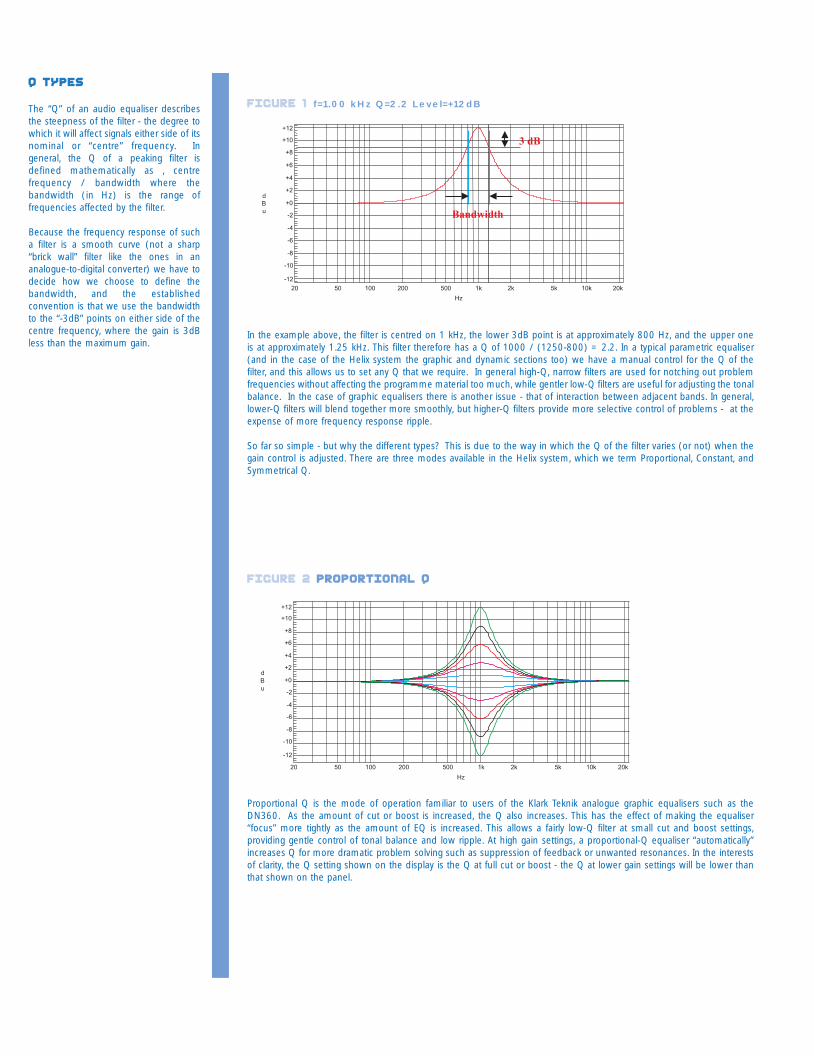
The “Q” of an audio equaliser describesthe steepness of the filter - the degree towhich it will affect signals either side of itsnominal or “centre” frequency. Ingeneral, the Q of a peaking filter isdefined mathematically as , centrefrequency / bandwidth where thebandwidth (in Hz) is the range offrequencies affected by the filter.
Because the frequency response of sucha filter is a smooth curve (not a sharp“brick wall” filter like the ones in ananalogue-to-digital converter) we have todecide how we choose to define thebandwidth, and the establishedconvention is that we use the bandwidthto the “-3dB” points on either side of thecentre frequency, where the gain is 3dBless than the maximum gain.
In the example above, the filter is centred on 1 kHz, the lower 3dB point is at approximately 800 Hz, and the upper oneis at approximately 1.25 kHz. This filter therefore has a Q of 1000 / (1250-800) = 2.2. In a typical parametric equaliser(and in the case of the Helix system the graphic and dynamic sections too) we have a manual control for the Q of thefilter, and this allows us to set any Q that we require. In general high-Q, narrow filters are used for notching out problemfrequencies without affecting the programme material too much, while gentler low-Q filters are useful for adjusting the tonalbalance. In the case of graphic equalisers there is another issue - that of interaction between adjacent bands. In general,lower-Q filters will blend together more smoothly, but higher-Q filters provide more selective control of problems - at theexpense of more frequency response ripple.
So far so simple - but why the different types? This is due to the way in which the Q of the filter varies (or not) when thegain control is adjusted. There are three modes available in the Helix system, which we term Proportional, Constant, andSymmetrical Q.
Proportional Q is the mode of operation familiar to users of the Klark Teknik analogue graphic equalisers such as theDN360. As the amount of cut or boost is increased, the Q also increases. This has the effect of making the equaliser“focus” more tightly as the amount of EQ is increased. This allows a fairly low-Q filter at small cut and boost settings,providing gentle control of tonal balance and low ripple. At high gain settings, a proportional-Q equaliser “automatically”increases Q for more dramatic problem solving such as suppression of feedback or unwanted resonances. In the interestsof clarity, the Q setting shown on the display is the Q at full cut or boost - the Q at lower gain settings will be lower thanthat shown on the panel.
figure 2 Proportional q
figure 1 f=1.00 kHz Q=2.2 Level=+12dB
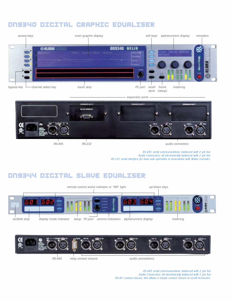
access keys encoderssoft keysmain graphic display alphanumeric display
expansion ports
alphanumeric displaycomms indicatorsdisplay mode indicatorscribble strip
remote control active indicator or “ME” light up/down keys
metering
metering
bypass key home(setup)
recallstore
PC port
setup PC port
touch stripchannel select key
RS-232RS-485
RS-485 relay contact closure audio connections
audio connectors
DN9340 digital graphic equaliser
DN9344 digital slave equaliser
RS-485 serial communications: balanced with 2 pin hotAudio Connectors: all electronically balanced with 2 pin hot
RELAY: contact closure, this allows a simple contact closure to recall memories.
RS-485 serial communications: balanced with 2 pin hotAudio Connectors: all electronically balanced with 2 pin hot
RS-232 serial interface for auto solo operation in association with Midas consoles.
KT helix brochure plan 3/3/03 8:35 am Page 9
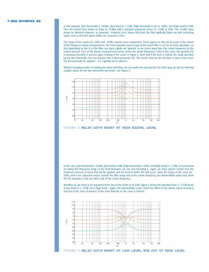
In this example, [low threshold] is -20dBu, [low level] is +12dB, [high threshold] is set to -5dBu, and [high level] is 0dB.Thus the lowest trace shows an input at -25dBu with a standard parametric boost of +12dB at 1kHz. The -20dBu traceshows an identical response, as expected. However, once above this level, the filter gradually fades out with increasingsignal, until at all levels above 0dBu, the response is flat.
The shape of the curves for -5dBu and -10dBu require some explanation. These appear as they do because of the natureof the frequency sweep measurement. The Helix equaliser uses a copy of the actual filter in use for its level calculation, sothat depending on the Q of the filter, our input signals are ‘ignored’ as we move away from the centre frequency by thecorrect amount. Thus as the sweep measurement moves across the centre frequency (1kHz in this case), the dynamic EQis ramping smoothly in and out again, leading to the curves in Figure 2. Note that if the level is outside the range specifiedby the two thresholds, the unit behaves like a fixed parametric EQ. This means that we do not have to guess how muchEQ will eventually be applied - it is explicitly set in advance.
Without changing modes or making any other selections, we can make the unit operate ‘the other way up’ just by selectingsuitable values for the two thresholds and levels see Figure 3.
In this case, [low threshold] is -20dBu, [low level] is 0dB, [high threshold] is -5dBu, and [high level] is +12dB, so that insteadof cutting this frequency range as the level increases, we are now boosting it. Again, we have precise control over themaximum amount of boost that will be applied, and the level at which this will occur. Note the shape of the curve for -5dBu, which has ‘expected values’ outside the filter range and at the centre frequency, but intermediate values that showthe EQ ramping in and out either side of the centre frequency.
Needless to say, there is no requirement for one of the levels to be 0dB. Figure 4 shows the transition from a +12dB boostat low level to a -12dB cut at high levels. Again, the intermediate curves show the effect of the sweep signal moving inand out of the ‘area of interest’ of the level detector as the curve is formed.
T-DEQ Dynamic EQ
figure 3 helix with boost at high signal level
figure 4 helix with boost at low level and cut at high level
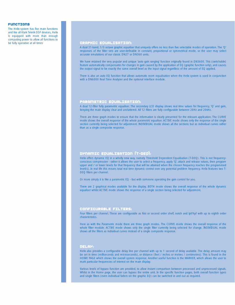
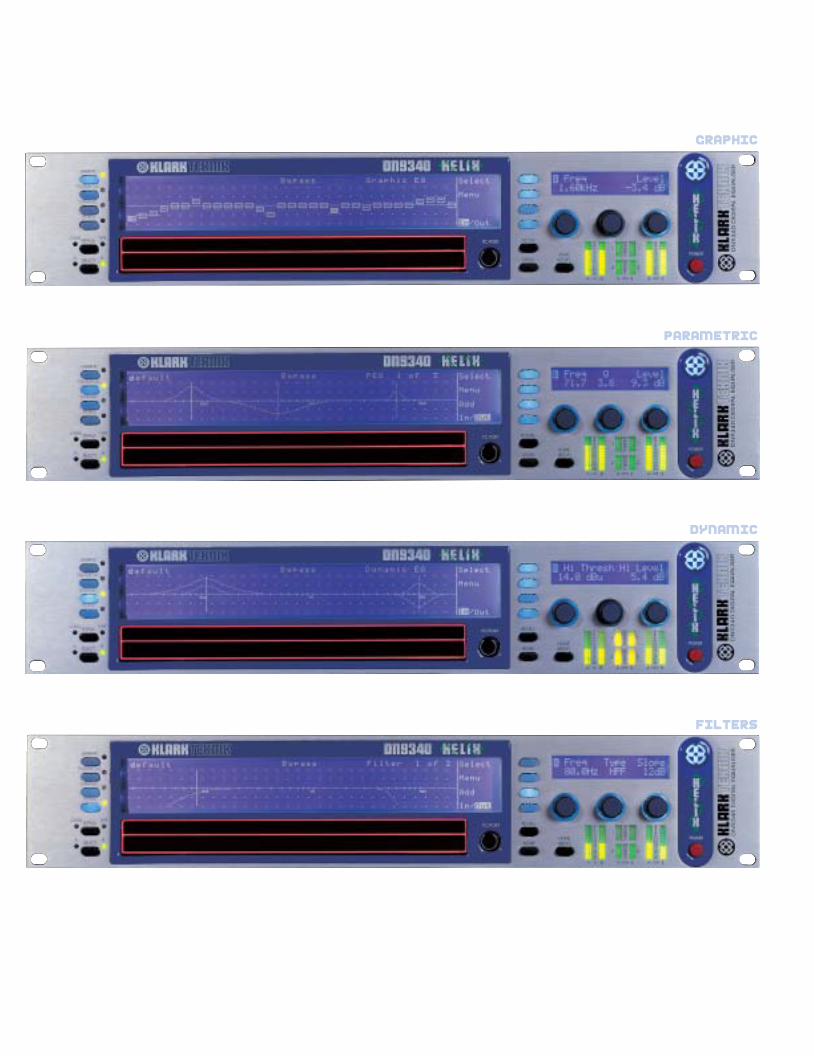
Graphic Equalisation:A dual 31-band, 1/3 octave graphic equaliser that uniquely offers no less than five selectable modes of operation. The ‘Q’responses of the filter sets are user-definable in constant, proportional or symmetrical mode, or the user may selectaccurate emulations of our classic DN27 or DN360 units.
We have retained the very popular and unique ‘auto gain ranging’ function originally found in DN3600. This (switchable)feature automatically compensates for changes in gain caused by the application of EQ (graphic function only), and causesthe output signal to be exactly the same overall level as the input signal regardless of the amount of EQ applied.
There is also an auto EQ function that allows automatic room equalisation when the Helix system is used in conjunctionwith a DN6000 Real Time Analyser and the optional interface module.
Parametric Equalisation:A dual 12-filter fully parametric equaliser. The secondary LCD display shows real time values for frequency, ‘Q’ and gain,keeping the main display clear and uncluttered. All 12 filters are fully configurable between 20Hz and 20kHz.
There are three graph modes to ensure that the information is clearly presented for the relevant application. The CURVEmode shows the overall response of the whole parametric equaliser. ACTIVE mode shows only the response of the singlesection currently being selected for adjustment. INDIVIDUAL mode shows all the sections but as individual curves ratherthan as a single composite response.
Dynamic Equalisation (T-DEQ):Helix offers dynamic EQ in a wholly new way, namely Threshold Dependent Equalisation (T-DEQ). This is not frequency-conscious compression - rather it allows the user to select a frequency, apply ‘Q’, attack and release values, then programupper and / or lower levels for that frequency that will be attained when the chosen frequency reaches the programmedlevel(s). In real life this means total real time dynamic control over any potential problem frequency. Helix features two T-DEQ filters per channel.
Or more simply it is like a parametric EQ - but with someone operating the gain control for you.
There are 2 graphical modes available for the display. BOTH mode shows the overall response of the whole dynamicequaliser whilst ACTIVE mode shows the response of a single section being selected for adjustment.
Configurable Filters:Four filters per channel. These are configurable as first or second order shelf, notch and lpf/hpf with up to eighth ordercharacteristics.
Here as with the Parametric mode there are three graph modes. The CURVE mode shows the overall response of thewhole filter module. ACTIVE mode shows only the single filter currently being selected for change. INDIVIDUAL modeshows all the filters as individual curves instead of a single composite response.
Delay:Helix also provides a configurable delay line per channel with up to 1 second of delay available. The delay amount maybe set in time (milliseconds and microseconds), or distance (feet / inches or metres / centimetres). This is found in theHOME PAGE which shows the overall system response. Another useful function is the MARKER, which allows the user tomark particular frequencies of interest on the main display.
Various levels of bypass function are provided, to allow instant comparison between processed and unprocessed signals.Whilst in the Home page, the user can bypass the entire unit. In the specific function pages, both overall function typesand single filters (even individual faders on the graphic EQ) can be switched in and out as required.
FUNCTIONSThe Helix system has five main functionsand like all Klark Teknik DSP devices, Helixis equipped with more than enoughcomputing power to allow all functions tobe fully operative at all times
KT helix brochure plan 3/3/03 8:35 am Page 11
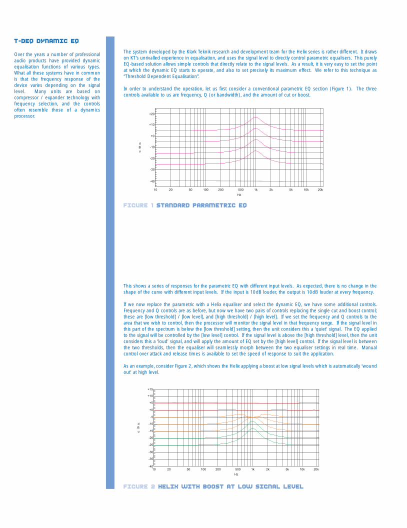
The system developed by the Klark Teknik research and development team for the Helix series is rather different. It drawson KT's unrivalled experience in equalisation, and uses the signal level to directly control parametric equalisers. This purelyEQ-based solution allows simple controls that directly relate to the signal levels. As a result, it is very easy to set the pointat which the dynamic EQ starts to operate, and also to set precisely its maximum effect. We refer to this technique as“Threshold Dependent Equalisation”.
In order to understand the operation, let us first consider a conventional parametric EQ section (Figure 1). The threecontrols available to us are frequency, Q (or bandwidth), and the amount of cut or boost.
This shows a series of responses for the parametric EQ with different input levels. As expected, there is no change in theshape of the curve with different input levels. If the input is 10dB louder, the output is 10dB louder at every frequency.
If we now replace the parametric with a Helix equaliser and select the dynamic EQ, we have some additional controls.Frequency and Q controls are as before, but now we have two pairs of controls replacing the single cut and boost control;these are [low threshold] / [low level], and [high threshold] / [high level]. If we set the frequency and Q controls to thearea that we wish to control, then the processor will monitor the signal level in that frequency range. If the signal level inthis part of the spectrum is below the [low threshold] setting, then the unit considers this a ‘quiet’ signal. The EQ appliedto the signal will be controlled by the [low level] control. If the signal level is above the [high threshold] level, then the unitconsiders this a ‘loud’ signal, and will apply the amount of EQ set by the [high level] control. If the signal level is betweenthe two thresholds, then the equaliser will seamlessly morph between the two equaliser settings in real time. Manualcontrol over attack and release times is available to set the speed of response to suit the application.
As an example, consider Figure 2, which shows the Helix applying a boost at low signal levels which is automatically ‘woundout’ at high level.
T-DEQ Dynamic EQ
Over the years a number of professionalaudio products have provided dynamicequalisation functions of various types.What all these systems have in commonis that the frequency response of thedevice varies depending on the signallevel. Many units are based oncompressor / expander technology withfrequency selection, and the controlsoften resemble those of a dynamicsprocessor.
figure 1 standard parametric eq
figure 2 helix with boost at low signal level
graphic
parametric
dynamic
filters
KT helix brochure plan 3/3/03 8:36 am Page 13
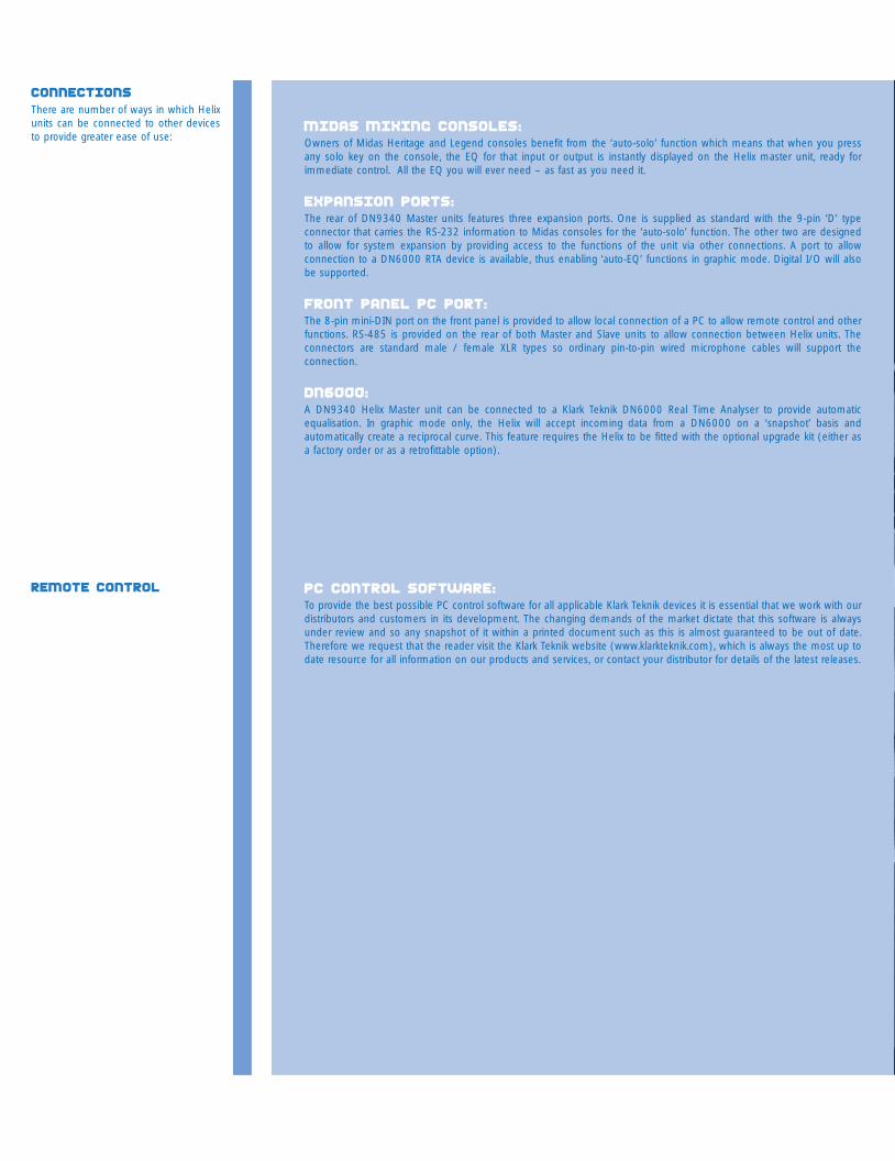
Midas mixing consoles:Owners of Midas Heritage and Legend consoles benefit from the ‘auto-solo’ function which means that when you pressany solo key on the console, the EQ for that input or output is instantly displayed on the Helix master unit, ready forimmediate control. All the EQ you will ever need – as fast as you need it.
expansion Ports:The rear of DN9340 Master units features three expansion ports. One is supplied as standard with the 9-pin ‘D’ typeconnector that carries the RS-232 information to Midas consoles for the ‘auto-solo’ function. The other two are designedto allow for system expansion by providing access to the functions of the unit via other connections. A port to allowconnection to a DN6000 RTA device is available, thus enabling ‘auto-EQ’ functions in graphic mode. Digital I/O will alsobe supported.
Front Panel PC Port:The 8-pin mini-DIN port on the front panel is provided to allow local connection of a PC to allow remote control and otherfunctions. RS-485 is provided on the rear of both Master and Slave units to allow connection between Helix units. Theconnectors are standard male / female XLR types so ordinary pin-to-pin wired microphone cables will support theconnection.
DN6000:A DN9340 Helix Master unit can be connected to a Klark Teknik DN6000 Real Time Analyser to provide automaticequalisation. In graphic mode only, the Helix will accept incoming data from a DN6000 on a ‘snapshot’ basis andautomatically create a reciprocal curve. This feature requires the Helix to be fitted with the optional upgrade kit (either asa factory order or as a retrofittable option).
PC control software:To provide the best possible PC control software for all applicable Klark Teknik devices it is essential that we work with ourdistributors and customers in its development. The changing demands of the market dictate that this software is alwaysunder review and so any snapshot of it within a printed document such as this is almost guaranteed to be out of date.Therefore we request that the reader visit the Klark Teknik website (www.klarkteknik.com), which is always the most up todate resource for all information on our products and services, or contact your distributor for details of the latest releases.
connectionsThere are number of ways in which Helixunits can be connected to other devicesto provide greater ease of use:
Remote control
KT helix brochure plan 3/3/03 8:36 am Page 15
The system developed by the Klark Teknik research and development team for the Helix series is rather different. It drawson KT's unrivalled experience in equalisation, and uses the signal level to directly control parametric equalisers. This purelyEQ-based solution allows simple controls that directly relate to the signal levels. As a result, it is very easy to set the pointat which the dynamic EQ starts to operate, and also to set precisely its maximum effect. We refer to this technique as“Threshold Dependent Equalisation”.
In order to understand the operation, let us first consider a conventional parametric EQ section (Figure 1). The threecontrols available to us are frequency, Q (or bandwidth), and the amount of cut or boost.
This shows a series of responses for the parametric EQ with different input levels. As expected, there is no change in theshape of the curve with different input levels. If the input is 10dB louder, the output is 10dB louder at every frequency.
If we now replace the parametric with a Helix equaliser and select the dynamic EQ, we have some additional controls.Frequency and Q controls are as before, but now we have two pairs of controls replacing the single cut and boost control;these are [low threshold] / [low level], and [high threshold] / [high level]. If we set the frequency and Q controls to thearea that we wish to control, then the processor will monitor the signal level in that frequency range. If the signal level inthis part of the spectrum is below the [low threshold] setting, then the unit considers this a ‘quiet’ signal. The EQ appliedto the signal will be controlled by the [low level] control. If the signal level is above the [high threshold] level, then the unitconsiders this a ‘loud’ signal, and will apply the amount of EQ set by the [high level] control. If the signal level is betweenthe two thresholds, then the equaliser will seamlessly morph between the two equaliser settings in real time. Manualcontrol over attack and release times is available to set the speed of response to suit the application.
As an example, consider Figure 2, which shows the Helix applying a boost at low signal levels which is automatically ‘woundout’ at high level.
T-DEQ Dynamic EQ
Over the years a number of professionalaudio products have provided dynamicequalisation functions of various types.What all these systems have in commonis that the frequency response of thedevice varies depending on the signallevel. Many units are based oncompressor / expander technology withfrequency selection, and the controlsoften resemble those of a dynamicsprocessor.
figure 1 standard parametric eq
figure 2 helix with boost at low signal level
graphic
parametric
dynamic
filters
KT helix brochure plan 3/3/03 8:36 am Page 13
In this example, [low threshold] is -20dBu, [low level] is +12dB, [high threshold] is set to -5dBu, and [high level] is 0dB.Thus the lowest trace shows an input at -25dBu with a standard parametric boost of +12dB at 1kHz. The -20dBu traceshows an identical response, as expected. However, once above this level, the filter gradually fades out with increasingsignal, until at all levels above 0dBu, the response is flat.
The shape of the curves for -5dBu and -10dBu require some explanation. These appear as they do because of the natureof the frequency sweep measurement. The Helix equaliser uses a copy of the actual filter in use for its level calculation, sothat depending on the Q of the filter, our input signals are ‘ignored’ as we move away from the centre frequency by thecorrect amount. Thus as the sweep measurement moves across the centre frequency (1kHz in this case), the dynamic EQis ramping smoothly in and out again, leading to the curves in Figure 2. Note that if the level is outside the range specifiedby the two thresholds, the unit behaves like a fixed parametric EQ. This means that we do not have to guess how muchEQ will eventually be applied - it is explicitly set in advance.
Without changing modes or making any other selections, we can make the unit operate ‘the other way up’ just by selectingsuitable values for the two thresholds and levels see Figure 3.
In this case, [low threshold] is -20dBu, [low level] is 0dB, [high threshold] is -5dBu, and [high level] is +12dB, so that insteadof cutting this frequency range as the level increases, we are now boosting it. Again, we have precise control over themaximum amount of boost that will be applied, and the level at which this will occur. Note the shape of the curve for -5dBu, which has ‘expected values’ outside the filter range and at the centre frequency, but intermediate values that showthe EQ ramping in and out either side of the centre frequency.
Needless to say, there is no requirement for one of the levels to be 0dB. Figure 4 shows the transition from a +12dB boostat low level to a -12dB cut at high levels. Again, the intermediate curves show the effect of the sweep signal moving inand out of the ‘area of interest’ of the level detector as the curve is formed.
T-DEQ Dynamic EQ
figure 3 helix with boost at high signal level
figure 4 helix with boost at low level and cut at high level
Graphic Equalisation:A dual 31-band, 1/3 octave graphic equaliser that uniquely offers no less than five selectable modes of operation. The ‘Q’responses of the filter sets are user-definable in constant, proportional or symmetrical mode, or the user may selectaccurate emulations of our classic DN27 or DN360 units.
We have retained the very popular and unique ‘auto gain ranging’ function originally found in DN3600. This (switchable)feature automatically compensates for changes in gain caused by the application of EQ (graphic function only), and causesthe output signal to be exactly the same overall level as the input signal regardless of the amount of EQ applied.
There is also an auto EQ function that allows automatic room equalisation when the Helix system is used in conjunctionwith a DN6000 Real Time Analyser and the optional interface module.
Parametric Equalisation:A dual 12-filter fully parametric equaliser. The secondary LCD display shows real time values for frequency, ‘Q’ and gain,keeping the main display clear and uncluttered. All 12 filters are fully configurable between 20Hz and 20kHz.
There are three graph modes to ensure that the information is clearly presented for the relevant application. The CURVEmode shows the overall response of the whole parametric equaliser. ACTIVE mode shows only the response of the singlesection currently being selected for adjustment. INDIVIDUAL mode shows all the sections but as individual curves ratherthan as a single composite response.
Dynamic Equalisation (T-DEQ):Helix offers dynamic EQ in a wholly new way, namely Threshold Dependent Equalisation (T-DEQ). This is not frequency-conscious compression - rather it allows the user to select a frequency, apply ‘Q’, attack and release values, then programupper and / or lower levels for that frequency that will be attained when the chosen frequency reaches the programmedlevel(s). In real life this means total real time dynamic control over any potential problem frequency. Helix features two T-DEQ filters per channel.
Or more simply it is like a parametric EQ - but with someone operating the gain control for you.
There are 2 graphical modes available for the display. BOTH mode shows the overall response of the whole dynamicequaliser whilst ACTIVE mode shows the response of a single section being selected for adjustment.
Configurable Filters:Four filters per channel. These are configurable as first or second order shelf, notch and lpf/hpf with up to eighth ordercharacteristics.
Here as with the Parametric mode there are three graph modes. The CURVE mode shows the overall response of thewhole filter module. ACTIVE mode shows only the single filter currently being selected for change. INDIVIDUAL modeshows all the filters as individual curves instead of a single composite response.
Delay:Helix also provides a configurable delay line per channel with up to 1 second of delay available. The delay amount maybe set in time (milliseconds and microseconds), or distance (feet / inches or metres / centimetres). This is found in theHOME PAGE which shows the overall system response. Another useful function is the MARKER, which allows the user tomark particular frequencies of interest on the main display.
Various levels of bypass function are provided, to allow instant comparison between processed and unprocessed signals.Whilst in the Home page, the user can bypass the entire unit. In the specific function pages, both overall function typesand single filters (even individual faders on the graphic EQ) can be switched in and out as required.
FUNCTIONSThe Helix system has five main functionsand like all Klark Teknik DSP devices, Helixis equipped with more than enoughcomputing power to allow all functions tobe fully operative at all times
KT helix brochure plan 3/3/03 8:35 am Page 11
Q types
The “Q” of an audio equaliser describesthe steepness of the filter - the degree towhich it will affect signals either side of itsnominal or “centre” frequency. Ingeneral, the Q of a peaking filter isdefined mathematically as , centrefrequency / bandwidth where thebandwidth (in Hz) is the range offrequencies affected by the filter.
Because the frequency response of sucha filter is a smooth curve (not a sharp“brick wall” filter like the ones in ananalogue-to-digital converter) we have todecide how we choose to define thebandwidth, and the establishedconvention is that we use the bandwidthto the “-3dB” points on either side of thecentre frequency, where the gain is 3dBless than the maximum gain.
In the example above, the filter is centred on 1 kHz, the lower 3dB point is at approximately 800 Hz, and the upper oneis at approximately 1.25 kHz. This filter therefore has a Q of 1000 / (1250-800) = 2.2. In a typical parametric equaliser(and in the case of the Helix system the graphic and dynamic sections too) we have a manual control for the Q of thefilter, and this allows us to set any Q that we require. In general high-Q, narrow filters are used for notching out problemfrequencies without affecting the programme material too much, while gentler low-Q filters are useful for adjusting the tonalbalance. In the case of graphic equalisers there is another issue - that of interaction between adjacent bands. In general,lower-Q filters will blend together more smoothly, but higher-Q filters provide more selective control of problems - at theexpense of more frequency response ripple.
So far so simple - but why the different types? This is due to the way in which the Q of the filter varies (or not) when thegain control is adjusted. There are three modes available in the Helix system, which we term Proportional, Constant, andSymmetrical Q.
Proportional Q is the mode of operation familiar to users of the Klark Teknik analogue graphic equalisers such as theDN360. As the amount of cut or boost is increased, the Q also increases. This has the effect of making the equaliser“focus” more tightly as the amount of EQ is increased. This allows a fairly low-Q filter at small cut and boost settings,providing gentle control of tonal balance and low ripple. At high gain settings, a proportional-Q equaliser “automatically”increases Q for more dramatic problem solving such as suppression of feedback or unwanted resonances. In the interestsof clarity, the Q setting shown on the display is the Q at full cut or boost - the Q at lower gain settings will be lower thanthat shown on the panel.
figure 2 Proportional q
figure 1 f=1.00 kHz Q=2.2 Level=+12dB
access keys encoderssoft keysmain graphic display alphanumeric display
expansion ports
alphanumeric displaycomms indicatorsdisplay mode indicatorscribble strip
remote control active indicator or “ME” light up/down keys
metering
metering
bypass key home(setup)
recallstore
PC port
setup PC port
touch stripchannel select key
RS-232RS-485
RS-485 relay contact closure audio connections
audio connectors
DN9340 digital graphic equaliser
DN9344 digital slave equaliser
RS-485 serial communications: balanced with 2 pin hotAudio Connectors: all electronically balanced with 2 pin hot
RELAY: contact closure, this allows a simple contact closure to recall memories.
RS-485 serial communications: balanced with 2 pin hotAudio Connectors: all electronically balanced with 2 pin hot
RS-232 serial interface for auto solo operation in association with Midas consoles.
KT helix brochure plan 3/3/03 8:35 am Page 9
A constant Q equaliser has the same Q at all cut and boost settings. In other words, the bandwidth between the 3dBpoints does not change at all as the gain is adjusted. The really important thing to notice about this is that the resultingfrequency response is NOT symmetrical in cut and boost. This is because of the definition of Q which is based on the 3dBpoints relative to maximum gain. The maximum gain of the filter when in cut is, of course, 0dB, and the bandwidth isdetermined by the -3dB points relative to 0dB and NOT relative to the minimum gain (at the centre frequency). This makesa lot of sense musically too - if you listen to a music signal and apply a notch filter, and then change the shape of thecurve around the minimum gain (centre) point, it will make little difference to the sound (since that area is alreadyattenuated a lot). However, if you change the curve around the 3dB points, this will affect the sound much more, as moreor less of the signal “falls into” the notch. It is this bandwidth that the constant-Q filter is keeping constant. Note that manyequalisers that are described as “Constant Q” by their manufacturers do NOT fall into this category, and are what we wouldterm symmetrical-Q designs.
This class of equaliser has the same curves in boost as the constant-Q type, but then has cut responses that aresymmetrical with the boost ones. In other words, the bandwidth in cut is defined not according to our usual definition ofQ (see constant-Q above) but as “the point were the signal is cut by 3dB less than the maximum cut”. Most equalisersdescribed by their manufacturers as “Constant Q” in fact produce symmetrical responses..
Q types
figure 3 constant q
figure 4 Symmetrical q
DN9340:THE MASTER unitThe Helix system comprises two units.The DN9340 Helix Master unit is a two-rackspace, dual channel device fitted witha simple and intuitive user interfaceincluding two backlit LED displays and fullmetering for inputs, outputs and T-DEQfilters. DN9340s may be used individuallyas stereo (linked-channel) units or asdual discrete channel units, and may beconfigured to control or be controlled byother Helix units. All functions includingmemory recall are available from the frontpanel, as well as high-speed selection ofindividual channels of any connectedHelix units.
DN9344:THE SLAVE unitThe DN9344 Helix Slave is a singlerackspace unit that effectively containstwo DN9340s in one chassis, thusproviding four channels. The pairs ofchannels can be linked for stereooperation or operated independently.DN9344 has no front panel controlsother than those that allow the user toselect communications channels, but it isfitted with the same comprehensivemetering as the Master unit. Specificallyfor installation purposes, the Helix Slave isalso fitted with a contact closure interfaceon the rear so that a limited number ofuser presets can be recalled from asimple switch panel without the need fora Helix Master unit or PC. The audio signalpath of the unit is identical in everyrespect to the Master.
The DN9340 is designed to provide the user with a clear and intuitive interface with a large, bright and clear graphicdisplays allowing the optimum level of information to be relayed to the user. The keys and encoders enable straightforwardinteraction with the DN9340, this combined with the dual touch strip means the unit remains user friendly and its truecapability is never more than a touch away.
ENCODERS: These three encoders allow the selection of options and controlling values. Each encoder has an illuminatedblue ring surrounding it which indicates when the encoder is active.
ALPHANUMERIC DISPLAY: This display shows the parameter values for the current function being controlled by theencoder. This display also shows available options and text entered via the encoders.
SOFT KEYS: These four keys allow the selection of options and secondary functions. To aid operation they illuminate toshow which are active. Labelling for the soft keys is shown on the right of the main display.
HOME (SETUP): This key allows instant access to the home page from any of the individual EQ pages. In the home pageby pressing and holding the button for a second allows access to the set-up menu.
STORE and RECALL: These two keys allow the storing and recalling of up to 64 memory locations.
TOUCH STRIP: The two-part touch strip is used to select individual filters or to adjust gain selection. By pressing and holdingor tapping repeatedly the upper strip increases the level, while the lower, wider strip reduces the level. Pressing both theupper and lower strips simultaneously results in the creation of fader groups.
PC PORT: This RS-232 port allows the installation of software or control of the unit from a PC. This connector is entirelyseparate from the rear panel RS-485 connector and can be used at the same time.
METERING: The first pair of meters indicates the input level with multi-point clip indication. The middle group of fourmonitor all four T-DEQ dynamic EQs. The last pair show the output level. A red clip light indicates any internal clippingirrespective of the output level and is monitored at every processing stage.
ACCESS KEYS: These four keys active the controls for each type of equalisation: graphic, parametric, dynamic and filters.They illuminate to show which type of EQ is currently being controlled. Next to the keys is the EQ active light. This showswhether a particular EQ type is affecting the overall response.
BYPASS: This key when pressed whilst in the home page will bypass the complete unit for the selected channel. Whenpressed in an EQ mode the bypass operates on that type of EQ only.
SELECT: This key selects either A or B channel. If the channels are linked then this key will be inoperative.
The front panel of the DN9344 has a simple user interface as the main functions are controlled either by the DN9340master unit or through a PC remote.
ALPHANUMERIC DISPLAY: This shows the electronic scribble strip information, Last Memory Recalled and CommunicationsMode.
SETUP: This key when pressed and held allows access to the set-up menu, which is used to select the communicationschannel for remote control and to enable contact closure operation. The DN9344 has two independent communicationschannels as it contains the equivalent of two DN9340 master units.
METERING: The unit has two sets of independent meters for each of the two channels. The first pair of meters in each setindicate the input level with multi-point clip indication. The middle group of four monitor all four T-DEQ dynamic EQs. Thelast pair show output level. A red clip light indicates any internal clipping irrespective of the output level and is monitoredat every processing stage.
REMOTE CONTROL ACTIVE INDICATOR: This shows that the master unit is currently controlling the channel 1A, 1B, 2A or2B. This indicator is often referred to as the “ME” light.
DISPLAY MODE: When lit this indicates that the alphanumeric display are now showing Last Memory Recalled andCommunications Mode. When not lit, the displays are showing electronic scribble-strip names.
UP and DOWN keys: These keys are only active in the SETUP menu and are used to select the communications channelfor remote control and also contact closure mode.
PC PORT: This RS-232 port allows the installation of software or control of the unit from a PC. This connector is entirelyseparate from the rear panel RS-485 connector and can be used at the same time.
DATA INDICATORS: Show a visual indication of any data traffic from any of the external interfaces – RS-232, RS-485 andthe contact closure inputs.
SCRIBBLE STRIPS: Allow easy labelling of the units with a chinagraph pencil (replacement label kits are available).
KT helix brochure plan 3/3/03 8:35 am Page 7
Architects and Engineers SpecificationThe Digital Equaliser shall provide two audio channels in a standard 2U 19”rack mount chassis.
Each audio channel shall include: Input gain, delay up to one second; up tofour filters, two dynamic EQ bands, up to 12 parametric EQ bands and a 31band graphic EQ.
All delay times shall be set in milliseconds and microseconds, or in distanceunits (metric and imperial) with a temperature compensation facility.
The high and low pass filters shall be selectable from notch, high pass, lowpass, high shelf and low shelf types. The Low pass and high pass filters shallhave selectable slopes of 6, 12, 18, 24, 36 and 48 dB per octave and thehigh and low shelf filters shall have selectable slopes of 6 and 12 dB peroctave and ±12 dB of gain.
The dynamic EQ sections shall have independent high and low levelthresholds and gain and be selectable from parametric EQ, or high shelf orlow shelf filter types. The parametric EQ shall provide proportional-Q,constant-Q and symmetrical-Q responses. The dynamic EQ sections shallalso have independent attack and release times.
The parametric EQ sections shall have up to 12 dB of cut or boost and a Qvalue variable from 0.4 to 20. The parametric EQ shall provide proportional-Q, constant-Q and symmetrical-Q responses.
The graphic EQ section shall provide 31 bands on standard frequenciesdefined in BS EN ISO 266:1997. Proportional-Q, constant-Q andsymmetrical-Q responses shall be provided as well as emulations of KlarkTeknik DN27 and DN360 Graphic Equalisers.
Each Digital Equaliser shall meet or exceed the following performancespecifications:
• Frequency response ±0.3 dB (20 Hz to 20 kHz)• Distortion @ +4 dBu: <0.01% (20 Hz to 20 kHz)• Dynamic Range: 115 dB (20 Hz to 20 kHz unweighted)
All audio inputs and outputs shall be electronically balanced and use XLRconnectors. A 480 x 64 graphic LCD shall be provided to display a graphicalrepresentation of the equaliser section responses. All parameters shall bedisplayed and adjusted via a 20 x 2 alphanumeric LCD display, three rotaryencoders and individual menu buttons for each equaliser section. A dualtouchstrip shall be provided for use with the graphic LCD to allow theselection of graphic EQ band and gain, and centre or corner frequency forfilters, and dynamic and parametric EQ. The graphic and alphanumericLCDs and the dual touchstrip shall have LED backlights.
There shall be provision for 32 system memories and 32 factory presetswith a security lock-out feature. There shall also be a security lock-outfeature that is enabled when the unit is under remote control.
The Digital Equaliser shall be provided with RS-232 ports on the front andrear panels and RS-485 ports on the rear panel. The RS-485 ports and frontpanel RS-232 port shall be provided for remote control from a masterDigital Equaliser or a PC and additionally the front panel RS-232 port shallalso provide the facility to download software updates and preset memoriesinto the Digital Equaliser. The rear panel RS-232 port shall be provided forremote control from Midas Heritage and Legend mixing consoles.
The unit shall be capable of operating from a 100 to 240V, 50 to 60 Hz a.c.power source.
The Digital Equaliser shall be the Klark Teknik model DN9340 and noalternative option is available.
DN9340Digital Equaliser Master unit
Inputs TwoType Electronically balanced (pin 2 hot)Impedance (Ohm) 20kCommon Mode >80dB @ 1 kHzRejection
Outputs TwoType Electronically balanced (pin 2 hot)Maximum Level +21dBu into >2k
PerformanceFrequency response 0.3 dB with all filters and EQ flat(20Hz to 20kHz)Distortion (THD+N) @ +4dBu <0.01%(20Hz to 20 kHz)Dynamic range 115 dB(20Hz-20kHz unweighted)
Processing (Per Channel)Input Gain +12dB to -40dB in 0.1dB steps plus OffDelay 0-1 second
(342.25 m or 333'10” at 20C in 20.8us steps)Filters 4 Filters (max)Types Low Pass, High Pass, Low Shelf, High Shelf, NotchDynamic EQ 2 Bands (max)Range ±12dBResponses Proportional, Constant, SymmetricalParametric EQ 12 Bands (max)Range ±12dBResponses Proportional, Constant, SymmetricalGraphic EQ 31 Bands On ISO standard frequenciesRange ±12dBResponses Proportional, Constant, Symmetrical, DN27, DN360
Power RequirementsVoltage 90 V to 250 V a.c. 50/60 HzConsumption <40VA
TerminationsAudio inputs/outputs 3-pin XLRRS-485 inputs/outputs 3-pin XLRRS-232 8-pin Mini-DIN socket (front)
9-pin D-type (rear)Power 3-pin IEC
DimensionsWidth 483 mm (19inch)Height 88 mm (3.5 inch) 2RU HighDepth 303 mm (12 inch)
WeightNet 6kgShipping 8kg
technical specifications
KT helix brochure plan 3/3/03 8:35 am Page 5
Inputs FourType Electronically balanced (pin 2 hot)Impedance (Ohm) 20kCommon Mode >80dB @ 1 kHzRejection
Outputs FourType Electronically balanced (pin 2 hot)Maximum Level +21dBu into >2k
PerformanceFrequency response 0.3 dB with all filters and EQ flat(20Hz to 20kHz)Distortion (THD+N) @ +4dBu <0.01%(20Hz to 20 kHz)Dynamic range 115 dB(20Hz-20kHz unweighted)
Processing (Per Channel)Input Gain +12dB to -40dB in 0.1dB steps plus OffDelay 0-1 second
(342.25 m or 333'10” at 20C in 20.8us steps)Filters 4 Filters (max)Types Low Pass, High Pass, Low Shelf, High Shelf, NotchDynamic EQ 2 Bands (max)Range ±12dBResponses Proportional, Constant, SymmetricalParametric EQ 12 Bands (max)Range ±12dBResponses Proportional, Constant, SymmetricalGraphic EQ 31 Bands On ISO standard frequenciesRange ±12dBResponses Proportional, Constant, Symmetrical, DN27, DN360
Power RequirementsVoltage 90 V to 250 V a.c. 50/60 HzConsumption <40VA
TerminationsAudio inputs/outputs 3-pin XLRRS-485 inputs/outputs 3-pin XLRRS-232 8-pin Mini-DIN socket (front)Relay Socket 9-pin D-type (rear)Power 3-pin IEC
DimensionsWidth 483 mm (19 inch)Height 44 mm (1.75 inch) 1RU HighDepth 287 mm (12 inch)
WeightNett 4kgShipping 6kg
technical specifications
DN9344Digital Equaliser slave unit
Architects and Engineers SpecificationThe Digital Slave Equaliser shall provide four audio channels grouped astwo linkable pairs in a standard 2U 19” rack mount chassis.
Each audio channel shall include: Input gain, delay up to one second; up tofour filters, two dynamic EQ bands, up to 12 parametric EQ bands and a 31band graphic EQ.
All delay times shall be set in milliseconds and microseconds, or in distanceunits (metric and imperial) with a temperature compensation facility.
The high and low pass filters shall be selectable from notch, high pass, lowpass, high shelf and low shelf types. The Low pass and high pass filters shallhave selectable slopes of 6, 12, 18, 24, 36 and 48 dB per octave and thehigh and low shelf filters shall have selectable slopes of 6 and 12 dB peroctave and ±12 dB of gain.
The dynamic EQ sections shall have independent high and low levelthresholds and gain and be selectable from parametric EQ, or high shelf orlow shelf filter types. The parametric EQ shall provide proportional-Q,constant-Q and symmetrical-Q responses. The dynamic EQ sections shallalso have independent attack and release times.
The parametric EQ sections shall have up to 12 dB of cut or boost and a Qvalue variable from 0.4 to 20. The parametric EQ shall provide proportional-Q, constant-Q and symmetrical-Q responses.
The graphic EQ section shall provide 31 bands on standard frequenciesdefined in BS EN ISO 266:1997. Proportional-Q, constant-Q andsymmetrical-Q responses shall be provided as well as emulations of KlarkTeknik DN27 and DN360 Graphic Equalisers.
Each Digital Slave Equaliser shall meet or exceed the following performancespecifications:
• Frequency response ±0.3 dB (20 Hz to 20 kHz)• Distortion @ +4 dBu: <0.01% (20 Hz to 20 kHz)• Dynamic Range: 115 dB (20 Hz to 20 kHz unweighted)
All audio inputs and outputs shall be electronically balanced and use XLRconnectors.
There shall be two three-character starburst LED displays per pair of audiochannels for displaying recalled memory, communications channel settingand remotely-set user information. There shall also be physical write-onstrips for each pair of audio channels plus an additional one for the unit asa whole.
There shall be provision for 32 system memories and 32 factory presets.
The Digital Slave Equaliser shall be provided with an RS-232 port on thefront panel and RS-485 ports on the rear panel. The RS-485 ports and RS-232 port shall be provided for remote control from a master DigitalEqualiser or a PC and additionally the front panel RS-232 port shall alsoprovide the facility to download software updates and preset memories intothe Digital Slave Equaliser. There shall also be a rear panel relay contactclosure port to allow the recall of specific preset memories.
The unit shall be capable of operating from a 100 to 240V, 50 to 60 Hz a.c.power source.
The Digital Slave Equaliser shall be the Klark Teknik model DN9344 and noalternative option is available.
introductionThe new Klark Teknik Helix system provides an intuitive yet sophisticated and flexible audio equalisation systemin a very compact package. Its unique selection of functions allows EQ to be applied with total precision, usingthe types and combinations of filters that deal most effectively with a given situation. Like all Klark Teknik DSPdevices, Helix is equipped with more than enough computing power to allow all functions to be fully operativeat all times.
Helix also offers a specific advantage to owners of MIDAS Heritage and Legend consoles, in the form of an 'auto-solo' function which allows instant access to all the Helix functions allocated to that input or output.
The principal operational advantage of Helix is that it offers all the functionality of several standalone devices inone package, thus saving massively on both cost and rackspace. For instance, enough EQ for a 24-way monitormix plus two sidefills will fit into just EIGHT rackspaces (six DN9344 slaves and one DN9340 Master), at almostexactly the same cost as the same number of channels of top-class analogue graphic EQ.
Like all KT units it is engineered to the highest standards and carries the usual KT 5-year transferableinternational factory warranty.
DN9340
2 c
hannels, 31
bands 1
/3 O
ctave d
igital f
ilters i
n 5
different f
ilter e
mulations p
er c
hannel, 12
bands 2
0Hz-2
0kHz o
f p
aram
etric e
qualisation p
er c
hannel, 2 b
ands o
fthreshold d
ependent e
qualisation (T-D
EQ) per c
hannel, 4
first t
o e
ighth o
rder f
ilters p
er c
hannel, 1
second o
f d
elay p
er c
hannel
DN9344
4 c
hannels, 31
bands, 1/
3 O
ctave d
igital f
ilters i
n 5
different f
ilter e
mulations p
er c
hannel, 12
bands, 20Hz-2
0kHz o
f p
aram
etric e
qualisation p
er c
hannel, 2 b
ands o
fthreshold d
ependent e
qualisation (T-D
EQ) per c
hannel, 4
first t
o e
ighth o
rder f
ilters p
er c
hannel, 1
second o
f d
elay p
er c
hannel
9340 details 3
9344 details 3
functions 5
connections 7
remote control 7
t-deq dynamic eq 9
Q types 11
9340 technical data 13
9344 technical data 14
KT helix brochure plan 3/3/03 8:35 am Page 3

SYSTEMG R A P H I C P A R A M E T R I C D Y N A M I C F I L T E R S
D N 9 3 4 0 D I G I T A L E Q U A L I S E R
D N 9 3 4 4 D I G I T A L E Q U A L I S E RIn 1974, brothers Phil and Terry Clarke founded Klark Teknik Research Ltd. In the years immediatelyfollowing, their innovative approach to design and development allowed them to introduce some trulygroundbreaking designs. The world’s first digital delay and digital reverb units emanated from theirlaboratory, and their descendants remain in common usage all over the world to this day. However, it wastheir concepts for equalisation devices that really changed the world of professional audio. Their earliestdesigns eventually matured into the world famous DN360 that remains the industry standard graphic EQfor audio professionals everywhere.
Today, Klark Teknik continues to uphold the original vision of the Clarke brothers: innovation in design,followed by uncompromising dedication to engineering and sonic quality. Most of our units are still madeand tested by hand, a time consuming and labour intensive process that remains the only method bywhich we can maintain the quality that our customers expect. Uniquely in its field, Klark Teknik also providesthe customer with an opportunity to invest in leading-edge equipment with an extraordinary workinglifespan and unrivalled retained value. Global support for our products is readily available from the factoryin Kidderminster, from our international distributor network and via the Klark Teknik website.
Klark Teknik Group, Walter Nash Road, Kidderminster, Worcestershire, DY11 7HJ. England.Tel: +44 1562 741515 Fax: +44 1562 745371email: [email protected] www.klarkteknik.com
KT helix brochure plan 3/3/03 8:35 am Page 1