Embed Size (px)
Citation preview

Safety Standards
of the Nuclear Safety Standards Commission (KTA)
KTA 3702 (2014-11) Emergency Power Generating Facilities with
Diesel-Generator Units in Nuclear Power Plants (Notstromerzeugungsanlagen mit Dieselaggregaten
in Kernkraftwerken)
The previous version of this safety standard was issued 2000-06
If there is any doubt regarding the information contained in this translation, the German wording shall apply.
Editor: KTA-Geschaeftsstelle c/o Bundesamt fuer kerntechnische Entsorgungssicherheit (BfE) Willy-Brandt-Str. 5 • 38226 Salzgitter • Germany Telephone +49 (0) 30 18333-1621 • Telefax +49 (0) 30 18333-1625


KTA SAFETY STANDARD
November 2014
Emergency Power Generating Facilities with Diesel-Generator Units in Nuclear Power Plants KTA 3702
Previous versions of this safety standard: KTA 3702 2000-06 (BAnz No. 159a of August 24, 2000) KTA 3702.1 1980-06 (BAnz No. 185a of October 3, 1980) KTA 3702.2 1991-06 (BAnz No. 7a of January 11, 1992)
Contents
Fundamentals 5
1 Scope 5
2 Definitions 5
3 Design 5
3.1 General Requirements 5
3.2 Power Balance and Static Tolerances 5
3.3 Power Load Steps and Dynamic Tolerances 6
3.4 Quiet-run Tolerances 7
3.5 Power Rating and Number of the Diesel-generator Units in each Train 7
3.6 Suitability 7
3.7 Diesel Engine Requirements 8
3.8 Requirements for the Generator 9
3.9 Requirements for Auxiliary Systems 9
3.10 Diesel Generator Unit 10
3.11 Local Control Station 10
3.12 Instrumentation and Control Systems 11
3.13 Testability 12
4 Documents to be Submitted 14
4.1 General Requirements 14
4.2 Documents on the Design of the Emergency Power Generating Facilities 14
4.3 Documents on the Diesel Engine 14
4.4 Documents on the Generator 14
4.5 Documents on the Auxiliary Systems 14
4.6 Documents on the Instrumentation and Control Equipment 15
4.7 Documents on the Type Tests and Routine Tests15
4.8 Documents on Tests and Inspections During On-site Assembly, Commissioning and In-service Inspection 15
4.9 Documents on Tests During Repairs 15
5 Suitability Tests, Type Tests, and Routine Tests 15
5.1 Type Test of the Diesel Engine 15
5.2 Routine Test and Acceptance Test of the Diesel Engine 18
5.3 Type Test of the Generator 19
5.4 Routine Test of the Generator 19
5.5 Suitability Test for Components of the Auxiliary Systems 19
5.6 Routine Tests of the Components of the Auxiliary Systems 19
5.7 Suitability Test for Components of the Instrumentation and Control Equipment 19
5.8 Routine Tests of the Components of the Instrumentation and Control Equipment 19
6 Tests and Inspections During On-site Assembly 25
7 Commissioning Tests 25
7.1 Tests and Inspections during Pre-nuclear Operation 25
7.2 Tests During Initial Nuclear Startup Operation 26
7.3 Tests After Modifications 26
8 In-service Inspections 26
8.1 General Requirements 26
8.2 Function Test Run 26
8.3 Test Run at Overload Power Capacity 26
8.4 72-h-test run 26
8.5 Testing the Instrumentation and Control Equipment 27
8.6 Examination of the Operating Media 27
9 Operation, Servicing, and Repair 27
9.1 General Requirements 27
9.2 Operation of the Emergency Power Generating Facility 27
9.3 Servicing and Repair 27
10 Tests Subsequent to Servicing or Repair 28
11 Testers 28
12 Test Certification and Documentation 28
Appendix A Monitoring and Protective Shutdown of an Emergency Power Generating Facility with a Standby Diesel Generator Unit 29
Appendix B Design Example for the Equipment Protection of a Diesel Engine 31
Appendix C Design Example for the Equipment Protection of a Generator 32
Appendix D Type Testing of a Diesel Engine 33
Appendix E Regulations Referred to in this Safety Standard 37
PLEASE NOTE: Only the original German version of this safety standard represents the joint resolution of the 35-member Nuclear Safety Standards Commission (Kerntechnischer Ausschuss, KTA). The German version was made public in the Federal Gazette (Bundesanzeiger) of January 23, 2013. Copies of the German version may be mail-ordered through the Wolters Kluwer Deutschland GmbH ([email protected]). Downloads of the English translations are available at the KTA website (http://www.kta-gs.de).
All questions regarding this English translation should please be directed to:
KTA-Geschaeftsstelle c/o BfE, Willy-Brandt-Str. 5, D-38226 Salzgitter, Germany or [email protected]

Comments by the Editor: Taking into account the meaning and usage of auxiliary verbs in the German language, in this translation the following agreements are effective:
shall indicates a mandatory requirement,
shall basically is used in the case of mandatory requirements to which specific exceptions (and only those!) are permitted. It is a requirement of the KTA that these exceptions - other than those in the case of shall normally - are specified in the text of the safety standard,
shall normally indicates a requirement to which exceptions are permissible. However, exceptions used shall be substantiated during the licensing procedure,
should indicates a recommendation or an example of good practice,
may indicates an acceptable or permissible method within the scope of this safety standard.

KTA 3702 Page 5
Fundamentals
(1) The safety standards of the Nuclear Safety Standards Com-mission (KTA) have the task of specifying those safety related requirements which shall be met with regard to precautions to be taken in accordance with the state of science and technology against the damage arising from the construction and operation of the facility (Section 7 para. 2 subpara. 3 Atomic Energy Act), in order to attain the protection goals specified in the Atomic En-ergy Act and Radiological Protection Ordinance (StrlSchV) and which are further detailed in “Safety Requirements for Nuclear Power Plants” (SiAnf). and “Interpretations of the Safety Require-ments for Nuclear Power Plants (Interpretations).
(2) Based on the Safety Requirements and their interpreta-tions this safety standard specifies the requirements for emer-gency power generating facilities with diesel-generator units.
(3) This safety standard was set up under the assumption that the conventional regulations and standards (e.g. German Acci-dent Prevention Regulations, DIN standards and VDE regula-tions) will be applied, in consideration of the specifics of the safety requirements for nuclear power plants.
(4) General requirements applying to the electrical power supply in nuclear power plants are specified in safety standard KTA 3701.
(5) Requirements for emergency power generating facilities with batteries and rectifiers in nuclear power plants are speci-fied in safety standard KTA 3703.
(6) Requirements for emergency power generating facilities with rotary converters and static inverters in nuclear power plants are specified in safety standard KTA 3704.
(7) Requirements for switchgear facilities, transformers and distribution networks for the electrical power supply of the safety system in nuclear power plants are specified in safety standard KTA 3705.
(8) Requirements for the fire protection of mechanical and electrical components are specified in safety standard KTA 2101.3.
(9) Requirements for Design of Components in Nuclear Power Plants against Seismic Events are specified in in safety standard KTA 2201.4
(10) Requirements for the reactor protection system and mon-itoring system of the safety system are specified in safety stand-ard KTA 3501.
(11) Requirements for Electrical Drive Mechanisms of the Safety System in Nuclear Power Plants are specified in safety standard KTA 3504
(12) General requirements for the quality assurance in nuclear power plants are specified in safety standard KTA 1401.
(13) Requirements for Ageing Management in Nuclear Power Plants are specified in safety standard KTA 1403.
(14) Requirements for Control Room, Remote Shutdown Sta-tion and Local Control Stations in Nuclear Power Plants are specified in safety standard KTA 3904.
1 Scope
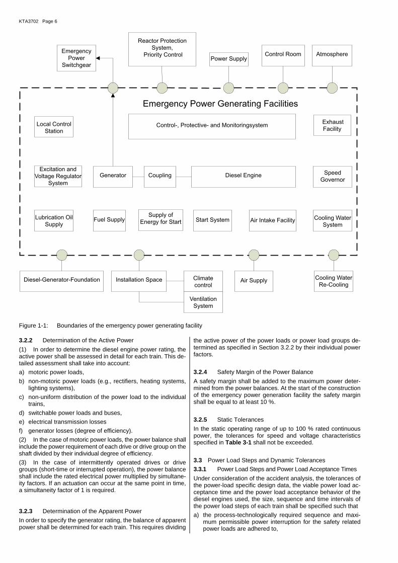
This safety standard applies to stationary emergency power generating facilities with diesel-generator units (referred to in this safety standard text as ‘emergency power generating facil-ity) in stationary nuclear power plants.
N o t e : The boundaries of an emergency power generating facility are shown in Figure 1-1.
2 Definitions
(1) Standby diesel-generator unit
A standby diesel-generator unit is a power generating unit driven by a diesel engine which, upon demand, will take over the power supply to a power load after a voltage interruption.
(2) Continuous operating time of diesel engine
The continuous operating time of the diesel engine is the man-ufacturer-approved uninterrupted running time for a specified power load cycle over a given time until a scheduled mainte-nance takes place with the diesel engine at standstill.
(3) Rated continuous power of diesel engine
The rated continuous power of the diesel engine is the highest power the diesel engine when used for an emergency power unit, can continuously supply at nominal speed and specified ambient conditions.
(4) Diesel-generator unit
A diesel-generator unit is a power generating unit consisting of a diesel engine, coupling and a generator mounted on a com-mon base frame / foundation
(5) Operating fuel tank
An operating fuel tank is a tank allocated to the individual diesel engine, which supplies the engine directly with fuel.
(6) Fuel storage tank
A fuel storage tank is a stationary tank designed for the storage of fuel that supplies the operating fuel tank.
3 Design
3.1 General Requirements
(1) For the design of the unit and its auxiliary systems, all ex-pected operational and incident-related loads on site and con-templable internal and external hazards shall be taken into ac-count. For this purpose, the documents shall be submitted ac-cording to Section 4.2 and 3.10.
(2) Design and installation of all parts of the emergency power generating facility shall normally be such that proper mainte-nance in accordance with requirements and short repair times are possible. Unambiguous instructions shall be provided for operation, servicing, and repair. The instructions of the manu-facturers shall be followed.
(3) The emergency power generating facilities for nuclear power plants shall normally employ standby diesel-generator units.
(4) It shall be demonstrated that the components of the emer-gency power generating facilities are quality-assured.
(5) The emergency diesel generator units of the emergency power generation systems in nuclear power plants shall be spa-tially separated and arranged train-by-train.
3.2 Power Balance and Static Tolerances
3.2.1 General Requirements
The emergency power requirement shall be determined by each train taking into account the design basis accidents to be consid-ered and the corresponding accident sequences. Hereby, the power requirements of all power loads that can be connected to one train in case of the individual design basis accident considered shall be determined.
KTA3702 Page 6
Figure 1-1: Boundaries of the emergency power generating facility
3.2.2 Determination of the Active Power
(1) In order to determine the diesel engine power rating, the active power shall be assessed in detail for each train. This de-tailed assessment shall take into account:
a) motoric power loads,
b) non-motoric power loads (e.g., rectifiers, heating systems, lighting systems),
c) non-uniform distribution of the power load to the individual trains,
d) switchable power loads and buses,
e) electrical transmission losses
f) generator losses (degree of efficiency).
(2) In the case of motoric power loads, the power balance shall include the power requirement of each drive or drive group on the shaft divided by their individual degree of efficiency.
(3) In the case of intermittently operated drives or drive groups (short-time or interrupted operation), the power balance shall include the rated electrical power multiplied by simultane-ity factors. If an actuation can occur at the same point in time, a simultaneity factor of 1 is required.
3.2.3 Determination of the Apparent Power
In order to specify the generator rating, the balance of apparent power shall be determined for each train. This requires dividing
the active power of the power loads or power load groups de-termined as specified in Section 3.2.2 by their individual power factors.
3.2.4 Safety Margin of the Power Balance
A safety margin shall be added to the maximum power deter-mined from the power balances. At the start of the construction of the emergency power generation facility the safety margin shall be equal to at least 10 %.
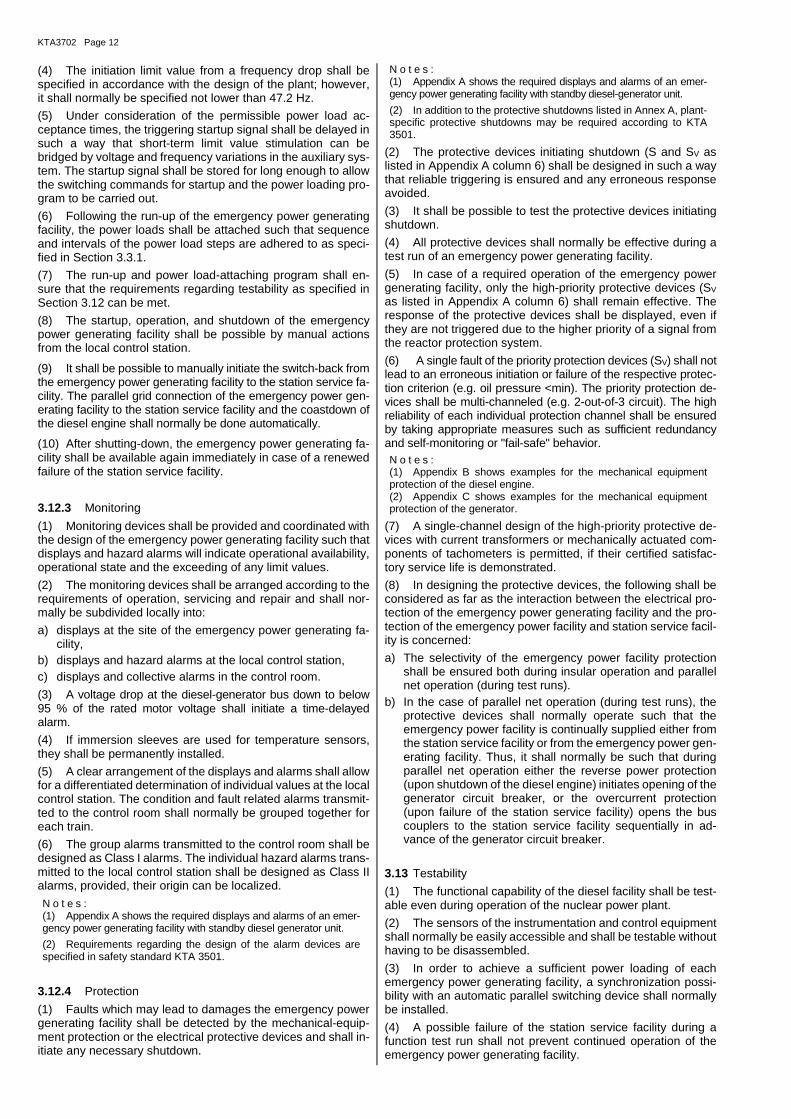
3.2.5 Static Tolerances
In the static operating range of up to 100 % rated continuous power, the tolerances for speed and voltage characteristics specified in Table 3-1 shall not be exceeded.
3.3 Power Load Steps and Dynamic Tolerances
3.3.1 Power Load Steps and Power Load Acceptance Times
Under consideration of the accident analysis, the tolerances of the power-load specific design data, the viable power load ac-ceptance time and the power load acceptance behavior of the diesel engines used, the size, sequence and time intervals of the power load steps of each train shall be specified such that
a) the process-technologically required sequence and maxi-mum permissible power interruption for the safety related power loads are adhered to,
Diesel-Generator-Foundation Installation Space Air Supply Cooling Water
Re-Cooling
Diesel EngineGenerator Speed
Governor
Start System Air Intake Facility Cooling Water
SystemFuel SupplyLubrication Oil
Supply
Exhaust
FacilityControl-, Protective- and Monitoringsystem
Emergency
Power
Switchgear
Reactor Protection
System,
Priority ControlPower Supply
Control Room Atmosphere
Climate
control
Ventilation
System
Excitation and
Voltage Regulator
System
Supply of
Energy for Start
Coupling
Emergency Power Generating Facilities
Local Control
Station
KTA 3702 Page 7
b) the permissible dynamic tolerances as specified in Sec-tion 3.3.2 are not exceeded, taking the transients into ac-count when the power loads are connected or disconnected and
c) the connection of power loads can be enabled by a simply structured program code. The program code shall be suited to trigger the emergency power supply at any point in time during the accident sequence.
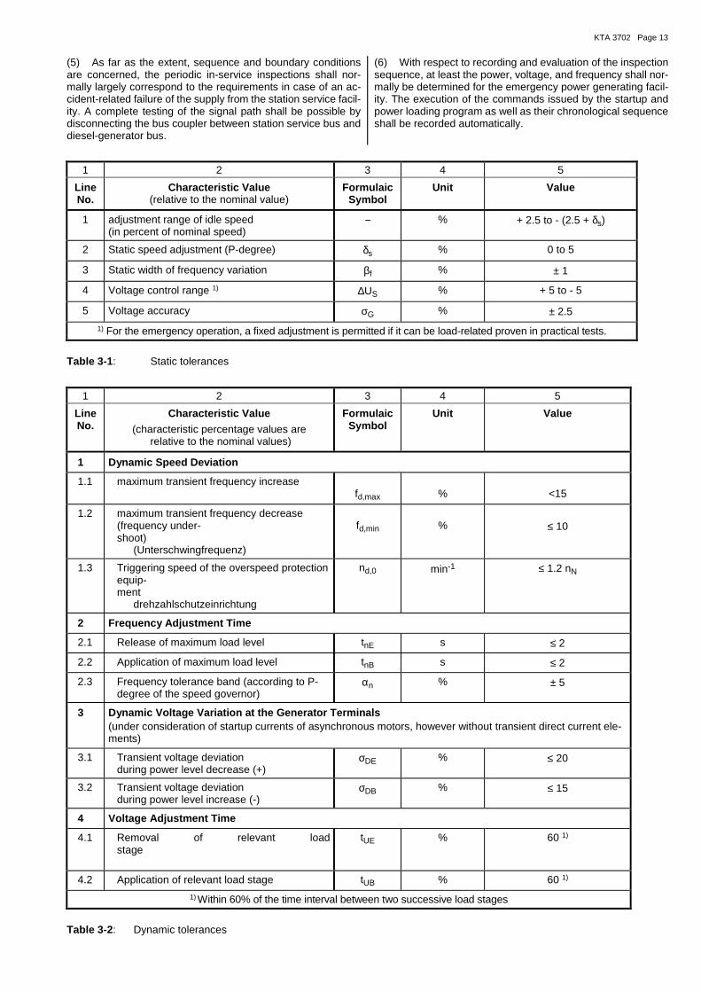
3.3.2 Dynamic Tolerances
In the case of power load changes up to the overload power capacity specified in Section 3.7.2, the dynamic tolerances of the speed and voltage characteristics specified in Table 3-2 shall not be exceeded.
3.4 Quiet-run Tolerances
(1) The vibrations transmitted from the diesel-generator unit to the structure and from the diesel engine to the generator shall be limited within the rotational speed adjustment range as follows:
a) The vibrational power loads transmitted from the diesel-gen-erator unit to the civil structure shall not exceed 3 % of the static power load.
b) The vibrations transmitted from the diesel engine to the gen-erator - superposed by the vibrations caused by the gener-ator itself - shall not exceed the vibration speed of the gen-erator.
N o t e : Vibration speeds may be defined e.g. in accordance with DIN ISO 8528-9.
(2) A torsional vibration analysis shall be carried out for the torsional vibration system of diesel engine, coupling and gener-ator to demonstrate that the vibration range does not include any critical values. This requires taking spark failures of one cylinder into account.
3.5 Power Rating and Number of the Diesel-generator Units in each Train
(1) The statically required power rating shall be specified on the basis of the power balance determined for each train (Sec-tions 3.2.2 and 3.2.3) including the safety margin (Sec-tion 3.2.4). The power rating of the diesel-generator unit shall be chosen such that it meets the dynamic tolerances as speci-fied in Section 3.3.2 taking the unit’s mass moment of inertia into account. The design of the diesel-generator unit shall be based on the most unfavorable ambient conditions at the instal-lation site.
(2) Each train shall normally be provided with one diesel-gen-erator unit.
3.6 Suitability
3.6.1 Suitability of the Emergency Power Generating Facility
(1) The suitability of the emergency power generating facility for use in nuclear power plants shall be demonstrated by a cer-tified satisfactory service life and by type tests as specified in Sections 3.6.2 to 3.6.5.
3.6.2 Suitability of the Diesel Engine
(1) Only such diesel engines, for which the suitability can be demonstrated by a certified satisfactory service life and by type tests, shall be used in the emergency power generation facili-ties [of nuclear power plants].
(2) The suitability of the diesel engine is deemed proven if:
a) a satisfactory service life is demonstrated by 15 diesel en-gines of the same series for a total of 7500 operating hours
whereby two of the diesel engines shall perform for at least 2000 operating hours each and
b) by a type test of diesel engines as specified in Appendix D.
(3) When using a diesel engine of lower power rating and speed, a type test may be regarded as successful if the compo-nents and parts relevant to engine operation are of the same design as those of the type-tested diesel engine.
(4) In the case of large-scale-production diesel engines for which considerably more operational experience is available than required under this safety standard, both the type and ex-tent of the type test may be specified differently from the de-tailed requirements of this safety standard.
(5) If the satisfactory service life of individual components or auxiliary systems justifiably cannot be demonstrated by testing diesel engines of the same design, a separate proof for these components [or auxiliary systems] is permissible.
(6) If the use in nuclear power plants requires additional safety features (e.g., a design to withstand external events) and these safety features are covered neither by type tests nor by the certified satisfactory service life, special suitability tests shall be provided.
3.6.3 Suitability of the Generator
(1) Prerequisite for the use of a generator [in a nuclear power plant] is that it is part of a production series with a certified sat-isfactory service life.
(2) The service life of a generator production series may be considered as successfully demonstrated if at least 15 genera-tors of this production series are in use.
(3) The generator type shall have successfully been sub-jected to a type test.
(4) If the use in nuclear power plants requires additional safety features (e.g., a design to withstand external events) and these safety features are covered neither by type tests nor by the certified satisfactory service life, special suitability tests shall be performed.
3.6.4 Suitability of the Auxiliary Systems
(1) The suitability of the auxiliary systems shall be demon-strated. A satisfactory service life shall normally have been demonstrated under comparable operating conditions for the components used.
(2) If the use in nuclear power plants requires additional safety features (e.g., a design to withstand external hazards) and these safety features are covered neither by type tests nor by the certified satisfactory service life, special suitability tests shall be performed.
3.6.5 Suitability of the Instrumentation and Control Systems
(1) The suitability of the instrumentation and control systems shall be demonstrated. The satisfactory service life of the com-ponents used shall normally have been demonstrated under comparable operating conditions
N o t e : Requirements for complex electronic components are demanded in KTA 3701 Section 5.16.3.
(2) If the use in nuclear power plants requires additional safety features (e.g. a design to withstand external hazards) and these safety features are covered neither by type tests nor by the certified satisfactory service life, special suitability tests shall be performed.
3.6.6 Suitability of operating media
Only operating media authorized by the component manufac-turers (e.g. fuel, lubricating oil or coolant) shall be used. The

KTA3702 Page 8
interactions and compatibilities of supplies with the components shall be observed.
3.7 Diesel Engine Requirements
3.7.1 Rated Continuous Power of the Diesel Engine
(1) The rated continuous power of the diesel engine shall amount to at least the sum of the required static active power as specified in Section 3.2.2, including the safety margin in Sec-tion 3.2.4.
(2) If the diesel engine is directly coupled with further compo-nents (e.g. pumps), the power requirements of the additional components shall be included in the calculation of continuous power.
3.7.2 Overload Power Capacity of the Diesel Engine
(1) The overload power capacity of a diesel engine shall be specified such that it is sufficient to comply with the dynamic tolerances as specified in Section 3.3.2 under consideration of the power load steps and power load acceptance times as specified in Section 3.3.1. The overload power capacity shall amount to at least 110 % of the rated continuous power as specified in Section 3.7.1. The overload power capacity may not be used to meet the static power requirements during emergency power operation; it shall, however, be provided for the duration of one hour for the performance certification.
(2) The quantity of injected fuel shall be limited such that the specified overload power capacity cannot be exceeded.
3.7.3 Continuous Operating Time of the Diesel Engine
The continuous operating time of the diesel engine and of the components relevant to engine function authorized by the man-ufacturer shall amount to at least 500 hours.
3.7.4 Minimal Permissible Power of the Diesel Engine
The load shall basically not fall below the manufacturer's spec-ified minimum permissible power in accordance with Table 4-1 for prolonged periods.
N o t e : In the event of temporary reduction below the specified level, the manufacturer's specifications are taken into account.
3.7.5 Overspeed Resistance of the Diesel Engine
The diesel engine including coupling shall be designed in such a way that the speed nd,0 specified in Table 3-2 No. 1.3 may be exceeded for a short time following the response of the over-speed limiting device.
3.7.6 Starter System of the Diesel Engine
(1) On diesel engines, pressurized air starters using com-pressed air acting on the pistons or a pneumatic starter on the flywheel shall basically be used.
(2) In the case of electrical starters equipped with individual, train-oriented starter batteries, all instrumentation and control devices fed by these batteries and used during the starting pro-cedure, e.g. the controls, shall be power regulated to account for the voltage drop during the starting procedure.
(3) The electrical actuation controls of the starter system shall close automatically following successful startup (i.e., igni-tion speed is exceeded). In case of an unsuccessful startup, the starter system shall be shut down after a specified time limit such that, with regard to the alarm limit-value of low-pressure in the compressed air supply system (see Section 3.9.2) or of low-voltage of the starter batteries, a sufficient energy supply re-mains for two successful starting procedures.
(4) The permissible duty cycle of the electrical and mechani-cal components of the starter system shall be at least three times longer than the duration up to time-limited shutoff.
(5) The starter system shall, in addition to the electrical actua-tion controls, be equipped with a manual actuation device. The manual device shall not prevent an electrical actuation.
(6) The requirements regarding the corrosion resistance of the charge-air supply system specified in Section 3.9.2 shall also apply to the air-pressurized components of the starter system.
3.7.7 Conditions for and Facilitation of Startup
(1) To ensure proper run-up and to provide for an immediate power loading, the following measures shall be taken already to be effective during standstill of the diesel engine:
a) preheating of the cooling water and the lubricating oil up to the specified minimum values,
b) automatic temperature control of the preheating of cooling water,
c) uniform warm-up by means of a circulation pump,
3.7.8 Diesel Engine Fuel System
(1) The diesel engine fuel system shall be installed or shielded such that leakages are prevented from coming into contact with components having surface temperatures above 220 °C. The high-pressure fuel lines shall be double-walled with leakage drain and detection or shall be provided with an equivalent shielding.
(2) Cutting ring screw connections in pressure-containing fuel lines are not permissible. Only metallic seals shall be used for connections in fuel injection lines.
(3) The autofrettage of high pressure lines shall be provided.
(4) All fuel lines shall be installed and fastened such that no damage can be caused by vibrations.
(5) Fuel booster pumps upstream of the injection pump shall normally be mechanically driven by the diesel engine.
(6) Filters shall be provided between operating fuel tank and injection pump. It shall be possible to clean the filters without shutting down the diesel-generator unit.
3.7.9 Lubricating Oil System
(1) The oil reservoir of the diesel engine shall be sufficient to ensure autonomous operation for at least 10 hours without fall-ing below the minimum level.
(2) Checking and replenishing the oil supply as well as sam-pling shall be possible during operation of the diesel-generator unit.
(3) The lubricating oil system of the diesel engine shall be in-stalled or shielded such that leakages are prevented from com-ing into contact with components having surface temperatures above 220 °C.
(4) The lubricating oil system of the diesel engine shall be pro-vided with a filter system. The filter system shall be designed such, that a cleaning will not become necessary within the time specified for continuous operation, or that it can be carried out without shutting down the diesel-generator unit. Any filter foul-ing shall be displayed (cf. Appendix A No. 4.3).
(5) The working pressure of controllers, which are required during the run-up process, shall be provided.
(6) Only such pre-lubrication equipment shall be used, that can cause no damage through over-lubrication.
3.7.10 Cooling System of the Diesel Engine
(1) An internal and an external cooling circuit shall be pro-vided to cool the diesel engine. The internal cooling circuit of
KTA 3702 Page 9
pre-charged diesel engines (charge-air compression) may con-sist of two separate circuits (engine circuit and charge-air cir-cuit). The external circuit may be cooled by a liquid coolant or by atmospheric air.
(2) The design of the heat exchanger shall be based on the most unfavorable values of temperature, pressure, and coolant flow rate in the external circuit. A safety margin of at least 10 % shall be applied to the analytically required capacity of the heat exchanger, taking the most unfavorable conditions into account. If fouling of the outer coolant circuit cannot be precluded, an ad-ditional margin of safety shall be applied on the capacity of the heat exchanger. For all circuits, the thermal characteristics of the used coolant shall be taken into account.
(3) The coolant in the internal circuit shall comply with the regulations of the engine manufacturer and shall be compati-ble with the materials used in the cooling circuit. A possibility of sampling shall be available to ensure the coolant quality.
(4) It shall be ensured that, following a failure-related shut-down of the diesel engine from the full-power-load condition, a subsequently performed renewed startup is not prevented by the shutdown limit value of the coolant temperature. This re-quirement does not apply in the case that this coolant temper-ature limit value is the cause of the failure-related shutdown of the diesel engine.
(5) In case of failure of the temperature control system, a manually controlled emergency operation of the diesel engine shall normally be possible.
(6) The alarm limit value in accordance with line no. 5.5 in Appendix A shall be chosen so that a period of at least 30 minutes is available for taking the necessary manual measures before the coolant preheating temperature specified by line 26 in Table 4.1 is reached.
3.7.11 Crankcase Ventilation and Crankcase Overpressure Protection
N o t e : Requirements for the design of safety devices are specified in the Guide Lines of Germanischer Lloyd.
(1) The crankcase ventilation shall be designed such that contaminants are prevented from entering the crankcase.
(2) In the case of diesel engines with a cylinder diameter larger than or equal to 200 mm or with a crank case volume larger than or equal to 0.6 m³, safety devices against overpres-sure in the crankcase shall be installed.
3.8 Requirements for the Generator
(1) The rated power of the generator shall be equal to at least the sum of the apparent power requirement specified in Sec-tion 3.2.3 plus the safety margin in Section 3.2.4.
(2) The generator and its excitation system shall be designed such that the static and dynamic tolerances as specified in Sec-tions 3.2.5 and 3.3.2 are not exceeded at rated power. The over-load power capacity shall be equal to at least that of the diesel engine as specified in Section 3.7.2. The maximum possible power load unbalance shall be taken into account.
(3) Magnitude and duration of the continuous short-circuit current shall enable a selective triggering of the protective de-vices associated with the connected emergency power facili-ties. The reactances shall be chosen such that the permissible dynamic voltage changes specified in Table 3-2 are not ex-ceeded in the case of power load changes.
3.9 Requirements for Auxiliary Systems
3.9.1 Superordinate Requirements
(1) The reliability of auxiliary systems whose function is re-quired for the designed start and operation of the diesel engine
or the generator and the reliability of the diesel engine or the generator shall match. For the design of these auxiliary systems, the following shall be considered:
a) The auxiliary systems are subject to the same safety-related requirements as the diesel engine and the generator itself.
b) The quality of the components in auxiliary systems shall be at least equal to the quality of the diesel engine and the gen-erator.
N o t e : Quality requirements are specified in KTA 1401.
(2) The design and construction shall provide for mainte-nance measures.
3.9.2 Supply of Energy for Start
3.9.2.1 Start Compressed Air Supply
(1) Each train of the emergency power generating facility shall be allocated to an individual compressed air supply tank and an individual compressed air supply system.
(2) The air pressure upstream of the main starter valve shall be continuously monitored and shall lead to an alarm when it falls below the limit value for automatic triggering of the com-pressed air supply system.
(3) Under consideration of the alarm limit value in para. 2, the charge-air supply of each diesel-generator unit shall be dimen-sioned such, that six consecutive automatic startup procedures would be possible. Furthermore, the dimensioning requirement as specified in Section 3.7.6 para. 5 shall be adhered to. In the case that compressed air tanks are connected in parallel, check valves shall be installed in the feed and discharge lines of each tank.
(4) If compressed air from the compressed air supply is needed for other tasks (e.g. for pneumatic controls), this shall be taken into account in the design of the compressed air gen-erating system.
(5) The capacity of the compressed air supply system shall be dimensioned such that after six startup operations indicated under para. 3, re-filling at a nominal pressure in about 45 min is possible. The air compressor shall be switched on and off au-tomatically depending on the pressure in the tanks. Possible isolation devices between the tanks and the starter valve shall be monitored or mechanically interlocked in the open position.
(6) It shall be possible to replenish the compressed air supply independently of the individual train.
(7) The compressed air supply system shall be designed in accordance with the following requirements:
a) The air-pressurized components of the compressed air sup-ply system shall be manufactured from corrosion-resistant materials.
b) The properties of the compressed air provided by the start compressed air supply (e.g. moisture, oil content, freedom from particles etc.) shall meet the specifications for reliable operation of the manufacturer of the diesel engine and of the manufacturer of the components of the start com-pressed air supply.
c) The design of the piping, pipe connections, and pipe carrier shall also take into account the operational vibration loads caused by the compressor.
d) Water drains shall be provided at the lowest points of the pipes and of the charge-air tanks.
e) The compressed air system shall be protected in such a way that the pressure does not exceed the design pressure.
3.9.2.1 Electrical Start-Energy-Supply
(1) The starter battery capacity per diesel generator shall be designed in such way, that six sequenced automatic successful starting procedures are possible.
KTA3702 Page 10
(2) Design, suitability, and testing shall be coordinated plant-specifically with the experts after 11 (3).
3.9.3 Fuel and Lubricating Oil Supply System
(1) The fuel shall be stored in an individual storage tank for each train of the emergency power generating facility from which it shall be pumped to the corresponding operating fuel tank.
(2) A leakage indicator shall be installed in the case of a dou-ble-walled fuel tank or of a single-walled fuel tank with collecting sump.
(3) It shall be possible to drain the water from the lowest point of each tank by suction from the top. Fuel extraction lines shall be installed at a sufficient height above the tank base.
(4) The operating fuel tank allocated to each train of the emer-gency power generating facility shall be installed at a point higher than the fuel booster pump on the diesel engine. An overflow to the storage tank shall be provided. The operating fuel tank shall be dimensioned such that the lowest permissible fuel level is sufficient for two hours of full-power-load operation.
(5) If the fuel level falls below the minimum value, an alarm shall be initiated (cf. Appendix A No. 3.5).
(6) The fuel storage tank and the operating fuel tank shall be dimensioned such that enough fuel can be stored for a 72 hour long operation of the emergency power generating facilities.
(7) The fuel required for a 24 hour long operation of an emer-gency power generating facility shall be stored individually for each train. The fuel required for an additional 48 hour long op-eration of all emergency power generating facilities may be stored on the site of the nuclear power plant.
(8) If individual diesel generator units are allocated to pro-cess-technological subsystems that fulfill their function in a shorter period of time, a fuel inventory for this shorter time pe-riod is sufficient.
(9) If the fuel inventory falls below the required quantity, an alarm shall be initiated (cf. Appendix A No. 3.3).
(10) The fuel supply system between fuel storage tank and op-erating tank shall ensure that the operating tank is refilled auto-matically. For this purpose, two switchable fuel-supply pumps and filters shall be installed.
(11) The fuel pump for refilling the operating tank shall be de-signed for a capacity of at least 110 % of the fuel consumption at overload power capacity. Self-charging pumps shall be in-stalled; these shall normally pump continuously during opera-tion of the diesel engine.
(12) The fuel supply from the operating tank to the diesel engine shall be designed in such a way that the diesel engine shall be safely supplied with fuel without the need for any auxiliary equip-ment and accidental draining of the fuel line and the operating tank is prevented. Connections in the fuel lines shall basically be welded or provided with welded flanges.
(13) The lubricating oil for the diesel-generator units shall be stored in sufficient quantity to correspond to the stored amount of the diesel fuel, regarding storage areas and storage deple-tion periods.
3.9.4 Air Supply System, Air Intake and Gas Exhaust Systems
(1) In specifying the necessary air supply for each train of the emergency power generating facility, the combustion air required for the diesel engine and the cooling air required for the diesel-generator units shall be taken into account. The design of the air supply system shall be based on the most unfavorable values of the air temperature at the installation site.
(2) Air intake and gas exhaust systems shall be designed such that mutual influences are prevented, in particular, an
air-side short circuit. Each diesel engine shall be provided with a separate gas exhaust line.
(3) Air intake, ventilation and heating systems shall be de-signed such that the required startup and operating temperature conditions for the diesel-generator unit and its auxiliary systems are not exceeded at the most unfavorable ambient temperatures.
(4) The safety function of those dampers that must open up to supply the combustion air shall be ensured and monitored.
(5) The air intake line of the diesel engine shall be provided with air filters.
(6) Gas exhaust lines shall be insulated and encased such that the surface temperature does not exceed 200 °C. It shall be ensured that neither fuel nor lubricating oil can penetrate into the insulation.
(7) Neither the gas exhaust lines nor the turbocharger shall be exposed to impermissible loads due to constrained thermal expansion.
3.9.5 External Cooling Circuit
(1) The design shall be based on the most unfavorable values for temperature, pressure, and throughput of the cooling medium.
(2) The materials of the components of the external coolant circuits shall be matched to the characteristics of the cooling media and cooling media flow rate in such a way that impermis-sible corrosion and deposits will not occur.
3.9.6 Energy Supply for Instrumentation, Control and Electrical Equipment
(1) The instrumentation, control and electrical equipment re-quired during startup of the diesel-generator unit shall be supplied by the direct current power facility for reasons of reliability.
(2) The power required for the instrumentation, control and electrical systems shall be supplied from the associated individ-ual train. If required for reasons of reliability, an additional pos-sibility for supplying power shall be provided.
(3) Cables and pipes in the vicinity of the emergency power generating facilities shall be designed or protected such that they will withstand the actual power loading (e.g., from fuel, oil, temperatures, and vibrations).
(4) The main cable ways shall be routed away from heated pipe lines as well as from pipe lines with combustible media.
3.10 Diesel Generator Unit
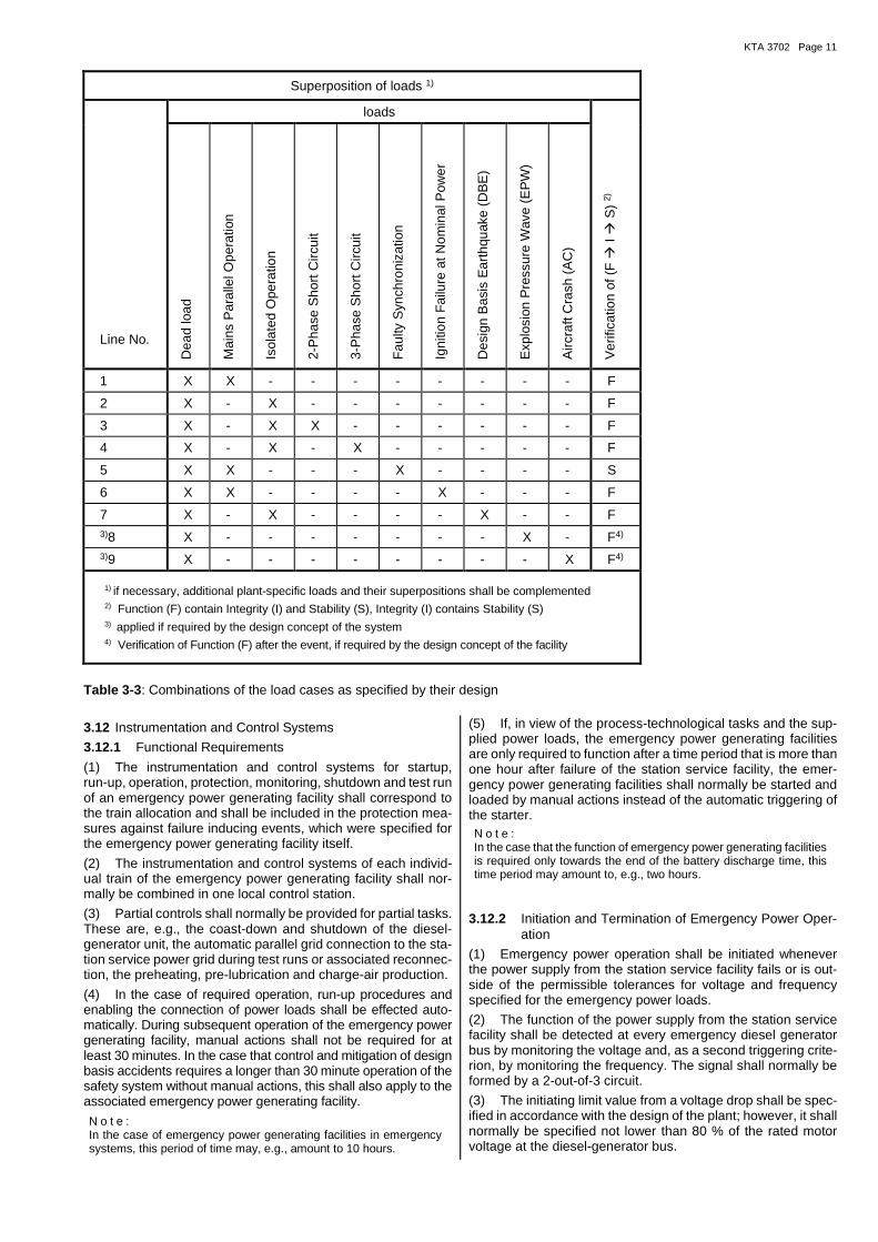
The design of the diesel generator unit shall depend on the load arising from the operation of the diesel engine, the overload power capacity of the diesel engine, the load from the genera-tor, the torsional vibration calculation and the external loads. In addition, a superposed load according to Table 3-3 shall be taken into account.
3.11 Local Control Station
(1) Each emergency power generating facility shall be pro-vided with an individual control station.
(2) The constructional planning and design of the control sta-tion shall meet the following requirements:
a) The control station shall be located in a separate room near the diesel-generator unit; the sound level at the control sta-tion shall not exceed 80 dB (A).
b) The control station shall be accessible other than from the turbine room. The turbine room shall be observable from the control station.
N o t e : Further requirements on the local control station are regulated in KTA 3904.
KTA 3702 Page 11
Superposition of loads 1)
Line No.
loads
Ver
ifica
tion
of (
F �
I �
S)
2)
Dea
d lo
ad
Mai
ns P
aral
lel O
pera
tion
Isol
ated
Ope
ratio
n
2-P
hase
Sho
rt C
ircui
t
3-P
hase
Sho
rt C
ircui
t
Fau
lty S
ynch
roni
zatio
n
Igni
tion
Fai
lure
at N
omin
al P
ower
Des
ign
Bas
is E
arth
quak
e (D
BE
)
Exp
losi
on P
ress
ure
Wav
e (E
PW
)
Airc
raft
Cra
sh (
AC
)
1 X X - - - - - - - - F
2 X - X - - - - - - - F
3 X - X X - - - - - - F
4 X - X - X - - - - - F
5 X X - - - X - - - - S
6 X X - - - - X - - - F
7 X - X - - - - X - - F 3)8 X - - - - - - - X - F4)
3)9 X - - - - - - - - X F4)
1) if necessary, additional plant-specific loads and their superpositions shall be complemented 2) Function (F) contain Integrity (I) and Stability (S), Integrity (I) contains Stability (S)
3) applied if required by the design concept of the system 4) Verification of Function (F) after the event, if required by the design concept of the facility
Table 3-3: Combinations of the load cases as specified by their design
3.12 Instrumentation and Control Systems
3.12.1 Functional Requirements
(1) The instrumentation and control systems for startup, run-up, operation, protection, monitoring, shutdown and test run of an emergency power generating facility shall correspond to the train allocation and shall be included in the protection mea-sures against failure inducing events, which were specified for the emergency power generating facility itself.
(2) The instrumentation and control systems of each individ-ual train of the emergency power generating facility shall nor-mally be combined in one local control station.
(3) Partial controls shall normally be provided for partial tasks. These are, e.g., the coast-down and shutdown of the diesel-generator unit, the automatic parallel grid connection to the sta-tion service power grid during test runs or associated reconnec-tion, the preheating, pre-lubrication and charge-air production.
(4) In the case of required operation, run-up procedures and enabling the connection of power loads shall be effected auto-matically. During subsequent operation of the emergency power generating facility, manual actions shall not be required for at least 30 minutes. In the case that control and mitigation of design basis accidents requires a longer than 30 minute operation of the safety system without manual actions, this shall also apply to the associated emergency power generating facility.
N o t e : In the case of emergency power generating facilities in emergency systems, this period of time may, e.g., amount to 10 hours.
(5) If, in view of the process-technological tasks and the sup-plied power loads, the emergency power generating facilities are only required to function after a time period that is more than one hour after failure of the station service facility, the emer-gency power generating facilities shall normally be started and loaded by manual actions instead of the automatic triggering of the starter. N o t e : In the case that the function of emergency power generating facilities is required only towards the end of the battery discharge time, this time period may amount to, e.g., two hours.
3.12.2 Initiation and Termination of Emergency Power Oper-ation
(1) Emergency power operation shall be initiated whenever the power supply from the station service facility fails or is out-side of the permissible tolerances for voltage and frequency specified for the emergency power loads.
(2) The function of the power supply from the station service facility shall be detected at every emergency diesel generator bus by monitoring the voltage and, as a second triggering crite-rion, by monitoring the frequency. The signal shall normally be formed by a 2-out-of-3 circuit.
(3) The initiating limit value from a voltage drop shall be spec-ified in accordance with the design of the plant; however, it shall normally be specified not lower than 80 % of the rated motor voltage at the diesel-generator bus.
KTA3702 Page 12
(4) The initiation limit value from a frequency drop shall be specified in accordance with the design of the plant; however, it shall normally be specified not lower than 47.2 Hz.
(5) Under consideration of the permissible power load ac-ceptance times, the triggering startup signal shall be delayed in such a way that short-term limit value stimulation can be bridged by voltage and frequency variations in the auxiliary sys-tem. The startup signal shall be stored for long enough to allow the switching commands for startup and the power loading pro-gram to be carried out.
(6) Following the run-up of the emergency power generating facility, the power loads shall be attached such that sequence and intervals of the power load steps are adhered to as speci-fied in Section 3.3.1.
(7) The run-up and power load-attaching program shall en-sure that the requirements regarding testability as specified in Section 3.12 can be met.
(8) The startup, operation, and shutdown of the emergency power generating facility shall be possible by manual actions from the local control station.
(9) It shall be possible to manually initiate the switch-back from the emergency power generating facility to the station service fa-cility. The parallel grid connection of the emergency power gen-erating facility to the station service facility and the coastdown of the diesel engine shall normally be done automatically.
(10) After shutting-down, the emergency power generating fa-cility shall be available again immediately in case of a renewed failure of the station service facility.
3.12.3 Monitoring
(1) Monitoring devices shall be provided and coordinated with the design of the emergency power generating facility such that displays and hazard alarms will indicate operational availability, operational state and the exceeding of any limit values.
(2) The monitoring devices shall be arranged according to the requirements of operation, servicing and repair and shall nor-mally be subdivided locally into:
a) displays at the site of the emergency power generating fa-cility,
b) displays and hazard alarms at the local control station, c) displays and collective alarms in the control room.
(3) A voltage drop at the diesel-generator bus down to below 95 % of the rated motor voltage shall initiate a time-delayed alarm.
(4) If immersion sleeves are used for temperature sensors, they shall be permanently installed.
(5) A clear arrangement of the displays and alarms shall allow for a differentiated determination of individual values at the local control station. The condition and fault related alarms transmit-ted to the control room shall normally be grouped together for each train.
(6) The group alarms transmitted to the control room shall be designed as Class I alarms. The individual hazard alarms trans-mitted to the local control station shall be designed as Class II alarms, provided, their origin can be localized.
N o t e s : (1) Appendix A shows the required displays and alarms of an emer-gency power generating facility with standby diesel generator unit.
(2) Requirements regarding the design of the alarm devices are specified in safety standard KTA 3501.
3.12.4 Protection
(1) Faults which may lead to damages the emergency power generating facility shall be detected by the mechanical-equip-ment protection or the electrical protective devices and shall in-itiate any necessary shutdown.
N o t e s : (1) Appendix A shows the required displays and alarms of an emer-gency power generating facility with standby diesel-generator unit.
(2) In addition to the protective shutdowns listed in Annex A, plant-specific protective shutdowns may be required according to KTA 3501.
(2) The protective devices initiating shutdown (S and SV as listed in Appendix A column 6) shall be designed in such a way that reliable triggering is ensured and any erroneous response avoided.
(3) It shall be possible to test the protective devices initiating shutdown.
(4) All protective devices shall normally be effective during a test run of an emergency power generating facility.
(5) In case of a required operation of the emergency power generating facility, only the high-priority protective devices (SV as listed in Appendix A column 6) shall remain effective. The response of the protective devices shall be displayed, even if they are not triggered due to the higher priority of a signal from the reactor protection system.
(6) A single fault of the priority protection devices (SV) shall not lead to an erroneous initiation or failure of the respective protec-tion criterion (e.g. oil pressure <min). The priority protection de-vices shall be multi-channeled (e.g. 2-out-of-3 circuit). The high reliability of each individual protection channel shall be ensured by taking appropriate measures such as sufficient redundancy and self-monitoring or "fail-safe" behavior. N o t e s : (1) Appendix B shows examples for the mechanical equipment protection of the diesel engine. (2) Appendix C shows examples for the mechanical equipment protection of the generator.
(7) A single-channel design of the high-priority protective de-vices with current transformers or mechanically actuated com-ponents of tachometers is permitted, if their certified satisfac-tory service life is demonstrated.
(8) In designing the protective devices, the following shall be considered as far as the interaction between the electrical pro-tection of the emergency power generating facility and the pro-tection of the emergency power facility and station service facil-ity is concerned:
a) The selectivity of the emergency power facility protection shall be ensured both during insular operation and parallel net operation (during test runs).
b) In the case of parallel net operation (during test runs), the protective devices shall normally operate such that the emergency power facility is continually supplied either from the station service facility or from the emergency power gen-erating facility. Thus, it shall normally be such that during parallel net operation either the reverse power protection (upon shutdown of the diesel engine) initiates opening of the generator circuit breaker, or the overcurrent protection (upon failure of the station service facility) opens the bus couplers to the station service facility sequentially in ad-vance of the generator circuit breaker.
3.13 Testability
(1) The functional capability of the diesel facility shall be test-able even during operation of the nuclear power plant.
(2) The sensors of the instrumentation and control equipment shall normally be easily accessible and shall be testable without having to be disassembled.
(3) In order to achieve a sufficient power loading of each emergency power generating facility, a synchronization possi-bility with an automatic parallel switching device shall normally be installed.
(4) A possible failure of the station service facility during a function test run shall not prevent continued operation of the emergency power generating facility.
KTA 3702 Page 13
(5) As far as the extent, sequence and boundary conditions are concerned, the periodic in-service inspections shall nor-mally largely correspond to the requirements in case of an ac-cident-related failure of the supply from the station service facil-ity. A complete testing of the signal path shall be possible by disconnecting the bus coupler between station service bus and diesel-generator bus.
(6) With respect to recording and evaluation of the inspection sequence, at least the power, voltage, and frequency shall nor-mally be determined for the emergency power generating facil-ity. The execution of the commands issued by the startup and power loading program as well as their chronological sequence shall be recorded automatically.
1 2 3 4 5
Line No.
Characteristic Value (relative to the nominal value)
Formulaic Symbol
Unit Value
1 adjustment range of idle speed (in percent of nominal speed)
− % + 2.5 to - (2.5 + δs)
2 Static speed adjustment (P-degree) δs % 0 to 5
3 Static width of frequency variation βf % ± 1
4 Voltage control range 1) ∆US % + 5 to - 5
5 Voltage accuracy σG % ± 2.5
1) For the emergency operation, a fixed adjustment is permitted if it can be load-related proven in practical tests.
Table 3-1: Static tolerances
1 2 3 4 5
Line No.
Characteristic Value
(characteristic percentage values are relative to the nominal values)
Formulaic Symbol
Unit Value
1 Dynamic Speed Deviation
1.1 maximum transient frequency increase fd,max
%
<15
1.2 maximum transient frequency decrease (frequency under-shoot) (Unterschwingfrequenz)
fd,min
%
≤ 10
1.3 Triggering speed of the overspeed protection equip-ment drehzahlschutzeinrichtung
nd,0 min-1 ≤ 1.2 nN
2 Frequency Adjustment Time
2.1 Release of maximum load level tnE s ≤ 2
2.2 Application of maximum load level tnB s ≤ 2
2.3 Frequency tolerance band (according to P-degree of the speed governor)
αn % ± 5
3 Dynamic Voltage Variation at the Generator Terminals (under consideration of startup currents of asynchronous motors, however without transient direct current ele-ments)
3.1 Transient voltage deviation during power level decrease (+)
σDE % ≤ 20
3.2 Transient voltage deviation during power level increase (-)
σDB % ≤ 15
4 Voltage Adjustment Time
4.1 Removal of relevant load stage
tUE % 60 1)
4.2 Application of relevant load stage tUB % 60 1)
1) Within 60% of the time interval between two successive load stages
Table 3-2: Dynamic tolerances
KTA3702 Page 14
4 Documents to be Submitted
4.1 General Requirements
(1) During the nuclear licensing procedure, it shall be shown by documents that the emergency power generating facilities are designed, fabricated, assembled, serviced, repaired and tested in accordance with the safety-related requirements.
(2) The review comprises the assessment of the documents on the design as specified in Section 4.2, on the component parts and components as specified in Sections 4.3 through 4.7, on the ability to carry out in-service inspections as specified in Section 4.8 and on the tests after repairs as specified in Sec-tion 4.9.
4.2 Documents on the Design of the Emergency Power Gen-erating Facilities
Documents shall be submitted showing that the design of the emergency power generating facilities, including their auxiliary systems, is in accordance with the safety-related requirements. These documents shall include:
a) a summary description of the required protection of the emergency power generating facilities against external events, and of the coordination with the protection concept of the emergency-power supplied process-technological systems,
b) a summary description of the required protection of the emergency power generating facilities against failure-initiat-ing events inside the power plant,
c) a description of the required redundancy of the emergency power generating facilities,
d) a summary description of the required functional independ-ence and separation, both spatial and with respect to fire pro-tection, of the emergency power generating facilities regard-ing their design as separate trains that are non-intermeshed and spatially separated or protected from each other,
e) an overview circuit diagram showing the circuitry of the emergency power generating facilities within the required electrical power supply of the safety-related power users,
N o t e : The documents under items a) through e) are only required to be sub-mitted, if they are not already part of the Safety Analysis Report.
f) power balances specifying for each train the individually re-quired emergency power for the accidents to be considered and their chronological sequence. The power chosen for the generator set shall be specified, and the safety margins used shall be substantiated,
g) proof that the design of the emergency power generating facilities is in accordance with most unfavorable ambient conditions at the installation site,
h) specification of the power load attachment time, size, chron-ological sequence and time interval of the intended power load steps and description of the coordination with the pro-cess-technological requirements,
i) specification of the characteristics regarding speed and volt-age values of the emergency power generating facilities within the specified tolerances,
k) demonstration that the emergency power generating facili-ties will stay functional, taking the operation-related vibra-tions, to be anticipated at the installation site and of the in-ternal and external events into account. For this purpose, a list of components shall be created which contains the de-fined safety-related requirements concerning stability, integrity, and functionality,
N o t e : Details of the proof (e.g. calculation, design, material engineer-ing, welding practice, test technique) may be listed in a separate document e.g. in a specification.
l) assembly drawing of the emergency power generating facil-ities with its supports and the anchoring connections in the foundation,
m) general arrangement drawings of the buildings that house emergency power generating facilities and component ar-rangement drawings of the diesel generator units and their auxiliary systems, including the routing of pipes and cables as well as a summary description regarding arrangement and installation,
n) documents for operation, servicing and repairs,
o) the fire protection measures, as well as the precautionary measures against human errors, shall be demonstrated within the scope of the overall concept for the nuclear power plant,
p) proof of the torsional strength of the coupling between en-gine and generator in consideration of the overload power capacity of the diesel engine and the short-circuit torque of the generator.
4.3 Documents on the Diesel Engine
It shall be shown that the design of the diesel engine meets the safety-related requirements. This includes:
a) proof that the diesel engine is suited for its installation loca-tion and purpose of usage,
b) list of the drawing numbers of the main component parts of which it will be possible to verify that the diesel engine cor-responds to the one used in the suitability test,
c) drawings of the engine (assembly drawing), of the torsion-ally elastic or mechanical clutches at the engine output, and of the base frame,
d) proof that the crankshaft was calculated and designed in ac-cordance with the design requirements of one of the IACS classification societies,
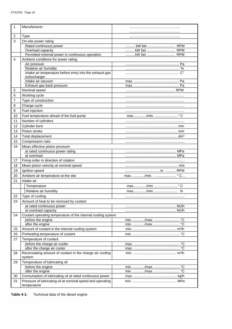
e) list of the technical data of the engine with special regard to the actual usage and intended power performance. The ex-tent is specified in Table 4-1,
f) list of the tests and inspections planned for the engine within the scope of the routine tests as specified in Section 5.2.
4.4 Documents on the Generator
It shall be shown that the design of the generator meets the safety-related requirements. This includes:
a) proof that the generator is suited for its installation location and purpose of usage,
b) drawings of the generator with its major dimensions, a de-scription and a functional diagram of the oil supply to the bearing, and of the excitation system,
c) list of the technical data of the generator with reference to the actual usage and the intended power performance; the extent is specified in Table 4-2,
d) proof of the design against damages during standstill, pro-vided, if roller bearings are used,
e) list of the tests and inspections planned for the generator within the scope of the tests as specified in Sections 5.3 and 5.4.
4.5 Documents on the Auxiliary Systems
It shall be shown that the design of the auxiliary systems meets the safety-related requirements. This includes:
a) proof that the auxiliary systems and their components are suited for their installation location and purpose of usage. This proof shall normally be submitted as a proof of satis-factory service life under comparable operating conditions

KTA 3702 Page 15
and, if required, by supplementary suitability tests as speci-fied in Section 5.5,
b) circuit diagrams with a summary description, indications of the measurement locations and a list of components for the
ba) compressed-air system,
bb) fuel system,
bc) lubricating oil system,
bd) air intake system and gas exhaust system,
be) coolant system,
c) analytical proof that the components of the auxiliary sys-tems are designed in accordance with the safety related re-quirements. These are, essentially:
ca) dimensioning of the compressed-air supply and the compressed-air generating facility,
cb) dimensioning of the fuel supply and the lubricating oil supply,
cc) design of the heat exchangers,
d) drawings of tanks and heat exchangers as well as their an-choring and support structures; isometric views of pipes in-cluding expansion joints and supports insofar as these are required for the necessary proofs (see section 4.2 item k),
e) welding specifications for those components with weld con-nections directly required for the function of the auxiliary system,
f) list of the components of the auxiliary systems and of the tests planned within the scope of tests as specified in Sec-tions 5.5 and 5.6.
4.6 Documents on the Instrumentation and Control Equipment
It shall be shown that the design of the instrumentation and con-trol equipment meets the safety-related requirements. This in-cludes:
a) summary description of the instrumentation and control equipment,
b) demonstration that the instrumentation and control equip-ment and their components are suited [for their installation location and purpose of usage],
This demonstration shall normally be submitted as a proof of satisfactory service life under comparable operating con-ditions and, if required, by supplementary suitability tests as specified in Section 5.7,
N o t e : Requirements for complex electronic components are specified in Section 5.16.3 of KTA 3701.
c) Function diagrams covering the
ca) run-up and power loading procedure,
cb) shut-down procedure,
cc) monitoring and protective devices including indications regarding the displays,
cd) alarm signals and protective shutdowns,
ce) interlocks,
cf) synchronization,
d) Measurement location data sheets,
e) Allocation list for the local control station,
f) A list of the technical data of the components of the instru-mentation and control equipment. This shall normally in-clude data for those components specified which are essen-tial to the implementation of the functions shown in the func-tion diagrams,
N o t e : If the instrumentation and control equipment of the emergency power generating facilities is identical to that of other systems important to safety, it is sufficient to provide a reference to the technical data of the components of this instrumentation and
control equipment that were submitted within the framework of the whole plant.
g) A list of the tests and inspections planned for the compo-nents of the instrumentation and control equipment in ac-cordance with Section 5.8.
4.7 Documents on the Type Tests and Routine Tests
Documents, as specified in Sections 5.1 through 5.4, 5.6 and 5.8, shall be submitted in form of a test list, which shall indicate the type and extent of the type tests and of the routine tests , the testers and the participation of authorized experts. These documents shall be adjusted to agree with nuclear licensing and supervisory procedures.
4.8 Documents on Tests and Inspections During On-site As-sembly, Commissioning and In-service Inspection
Documents on tests and inspections during on-site assembly as specified in Section 6, during commissioning as specified in Section 7 and during in-service inspection as specified in Sec-tion 8, shall be submitted.
4.9 Documents on Tests During Repairs
In the case of a thorough overhaul or in the case of comparable repairs, documents shall be submitted in form of a test list which shall indicate the type and extent of the tests and inspections during repairs, the testers and the participation of authorized experts. These documents shall be adjusted to agree with nu-clear licensing and supervisory procedures.
5 Suitability Tests, Type Tests, and Routine Tests
(1) The suitability may be proven by showing a successful service life and by a type test performed in accordance with the following Section 5.1.
(2) If proof is already provided under the provisions of IACS classification society or IEEE 387, the results shall normally be considered in the type test according to Section 5.1.
5.1 Type Test of the Diesel Engine
(1) The type test shall be performed in accordance with the requirements as specified in Appendix D or in Section 3.6.2 para. 4 with the participation of an expert in accordance with Section 11 para. 1.
(2) The type test shall meet the following general require-ments:
a) A test run shall be carried out on a test stand for a duration of 100 hours in accordance with a specified test program, and once for each engine type (cf. Table D-2).
b) The type test shall be carried out on a design-identical en-gine type intended for use in nuclear power plants, together with all component parts of the auxiliary systems that are attached to, or are driven by, the engine. Insofar as the pro-cess instrumentation and the heat exchangers of the outer coolant circuit are part of the equipment of the test stand, they are exempted from this requirement. Engines are con-sidered to be design-identical if their component parts are identical with respect to design, materials, and fabrication and if equivalent quality assurance measures are taken. In the case of the functionally important components, any de-viations from the proven fabrication series shall be specified and substantiated by proper references.
c) The manufacturer is permitted to repeat the type test in the case of a negative evaluation. Prerequisites for repeating the type test are a detailed assessment of the damage, ap-proval by the expert according to Section 11 para. 1 of the
KTA3702 Page 16
1 Manufacturer .................................................... .................................................... 2 Type ....................................................
3 On-site power rating Rated continuous power .......... kW bei ............................ RPM Overload capacity ......... kW bei ....................…..... RPM Permitted minimal power in continuous operation ......... kW bei ....................…..... RPM 4 Ambient conditions for power rating Air pressure ....................................................... Pa Relative air humidity ....................................................... % Intake air temperature before entry into the exhaust gas
turbocharger ....................................................... C°
Intake air vacuum max. .............................................. Pa Exhaust gas back pressure max. .............................................. Pa 5 Nominal speed .................................................. RPM
6 Working cycle ............................................................
7 Type of construction ............................................................
8 Charge cycle ............................................................
9 Fuel injection ............................................................
10 Fuel temperature ahead of the fuel pump max............../min. ........................ ° C
11 Number of cylinders ............................................................
12 Cylinder bore ..................................................... mm
13 Piston stroke ..................................................... mm
14 Total displacement ..................................................... dm³
15 Compression ratio .............................................................
16 Mean effective piston pressure at rated continuous power rating .................................................... MPa at overload .................................................... MPa 17 Firing order in direction of rotation .............................................................
18 Mean piston velocity at nominal speed ...................................................... m/s
19 Ignition speed ................................... to …....... RPM
20 Ambient air temperature at the site max….........../min. …..................... ° C…
21 Intake air
Temperature max............../min. ........................ ° C
Relative air humidity max............../min. ........................ %
22 Type of cooling .............................................................
23 Amount of heat to be removed by coolant at rated continuous power .................................................... MJ/h at overload capacity .................................................... MJ/h 24 Coolant operating temperature of the internal cooling system before the engine min. ............/max. .......................... °C after the engine min. ............/max. .......................... °C 25 Amount of coolant in the internal cooling system min. ............................................ m³/h
26 Preheating temperature of coolant min. ................................................ °C
27 Temperature of coolant before the charge air cooler max. ............................................... °C after the charge air cooler max. ............................................... °C 28 Recirculating amount of coolant in the charge air cooling
system min. ............................................ m³/h
29 Temperature of lubricating oil before the engine min. ............/max. .......................... °C after the engine min. ............/max. .......................... °C 30 Consumption of lubricating oil at rated continuous power max. ............................................ kg/h
31 Pressure of lubricating oil at nominal speed and operating temperature
min. ............................................. MPa
Table 4-1: Technical data of the diesel engine

KTA 3702 Page 17
32 Exhaust air turbocharger Manufacturer ............................................................. Type ............................................................. Speed at rated continuous power ................................................... RPM at overload capacity ................................................... RPM Temperature of exhaust gas at outlet at rated continuous power ........................................................ °C at overload capacity ........................................................ °C 33 Exhaust gas, mean temperature at the cylinder outlet
at overload capacity ………………….............................. °C
spread max. ..………………………………. K
34 Exhaust gas, temperature at the cylinder outlet max. ............................................... °C 35 Charging pressure ahead of cylinder at rated continuous power ..................................................... MPa at overload capacity ..................................................... MPa
36 Specific fuel consumption at rated continuous power ........................... ...................... g/kWh
37 Lubricating oil volume max............../min. ........................ dm³
38 Coupling between engine and generator Manufacturer ............................................................ Type ............................................................ Nominal torque ................................................ ... Nm Maximum permissible torque .................................................... Nm 39 Heat balance at rated continuous power Effective power ............. MJ/h = ............. % Power losses: heat amount of engine coolant ............. MJ/h = ............ % heat amount of lubricating oil ............. MJ/h = ............ % heat contribution fuel return ............. MJ/h = ............ % heat amount of charge air ............. MJ/h = ............ % heat amount of exhaust gas ............. MJ/h = ............ % heat amount of radiation energy ............. MJ/h = ............ % Total heat amount supplied by fuel ............. MJ/h = 100 %
40 Fuel injection pumps Single of unit pumps ....................................................... Manufacturer ....................................................... Type ....................................................... Start of injection before TDC in degrees of crankshaft
angle ..................................................... °
41 Fuel injection nozzles Manufacturer ....................................................... Type ....................................................... Ejection pressure ...............................................MPa 42 Intake valves Valve clearance ............. mm at ....................... °C Intake opens before TDC in degrees of crankshaft angle .................................................... ° Intake closes after TDC in degrees of crankshaft angle .................................................... °
43 Exhaust valves Valve clearance ............. mm at ...................... °C Exhaust opens before TDC in degrees of crankshaft an-
gle ................................................... °
Exhaust closes after TDC in degrees of crankshaft an-gle
.......................................... ........ °
44 Speed governor Manufacturer .................................................... P-degree from ...............% to .............. ....% Type ....................................................
Table 4-1: Technical data of the diesel engine (continued)

KTA3702 Page 18
1 Manufacturer .............................................. ..............................................
2 Type ..............................................
3 Nominal power ...................................... kVA
4 Nominal voltage ........................................... V
5 Nominal current ........................................... A
6 Current overload capability for 15 s .................-fold Nominal current
7 Power overload for 1 h (according to diesel engine, Table 4-1 No. 3) ....................................... kVA
8 Nominal frequency ......................................... Hz
9 Number of phases ..............................................
10 Nominal speed .................................... 1/min
11 Permissible overspeed .................................... 1/min
12 Thermal grade ..............................................
13 Torque of inertia .................................... kg m2
14 Coil connection ..............................................
15 Power factor ..............................................
16 Nominal exciting voltage .......................................... V
17 Nominal exciting current .......................................... A
18 efficiency at cos ϕ equal 0.8 and at
Generator power equal 1/4 nominal power .......................................... %
Generator power equal 2/4 nominal power .......................................... %
Generator power equal 3/4 nominal power .......................................... %
Generator power equal 4/4 nominal power .......................................... %
Generator power equal 5/4 nominal power .......................................... %
19 Synchronous-reactance xd (unsaturated) .......................................... %
20 Transient- reactance x´d (saturated) .......................................... %
21 Subtransient- reactance x"d (saturated) .......................................... %
22 Voltage adjustment range from ........... % to ............. %
23 Steady short-circuit current ......................................... kA
24 Short-circuit current impulse ......................................... kA
25 Type of construction ..............................................
26 Type of bearing and lubrication ..............................................
27 Degree of protection IP .........................................
28 Type of cooling .............................................
29 Ambient temperature ........................................ °C
30 Permissible absolute altitude ......................................... m
31 Weight ........................................ kg
32 Permissible alternating torsional torques …..................................... Nm
Table 4-2: Technical data of the generator
corrective actions to be taken, and the removal of all identi-fied defects.
d) The type test shall normally be carried out under the most unfavorable conditions of coolant and intake air permitted by the manufacturer.
e) Necessary deviations from the test program shall be agreed upon between the manufacturer and the expert according to Section 11 para. 1and shall be documented in the test report.
(3) The type test is considered successful if the following con-ditions are met:
a) the engine has achieved a total operating time of 100 hours under adherence to the power data specified in the test pro-gram,
b) the maximum permissible number of malfunctions specified in Section D 5 is not exceeded,
c) the results of the visual inspections specified in Section D.4 following the test run give no indications for the choice of wrong materials or for an overloading,
d) test records and measurement results of the test run indi-cate a positive result after their evaluation by the manufac-turer and review by the expert according to Sec-tion 11 para. 1.
(4) A test report on the type test shall be prepared and signed by both the expert according to Section 11 para. 1 and the engine manufacturer. The expert according to Sec-tion 11 para. 1 issues a certificate on the successful perform-ance of the type test.
5.2 Routine Test and Acceptance Test of the Diesel Engine
(1) A routine test shall be performed on each diesel engine.
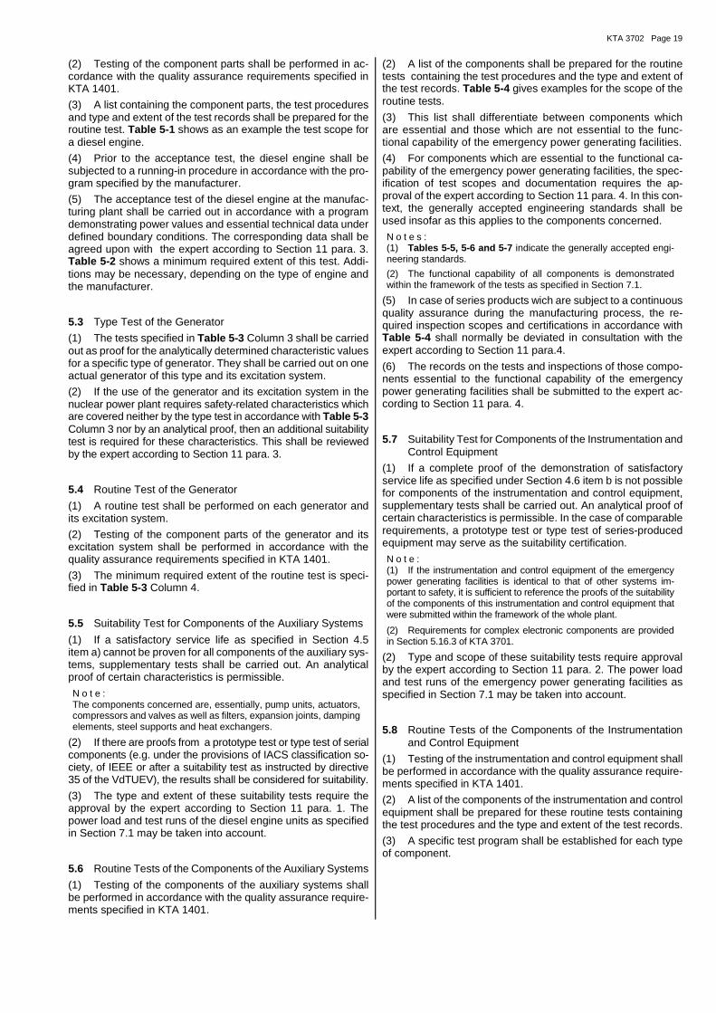
KTA 3702 Page 19
(2) Testing of the component parts shall be performed in ac-cordance with the quality assurance requirements specified in KTA 1401.
(3) A list containing the component parts, the test procedures and type and extent of the test records shall be prepared for the routine test. Table 5-1 shows as an example the test scope for a diesel engine.
(4) Prior to the acceptance test, the diesel engine shall be subjected to a running-in procedure in accordance with the pro-gram specified by the manufacturer.
(5) The acceptance test of the diesel engine at the manufac-turing plant shall be carried out in accordance with a program demonstrating power values and essential technical data under defined boundary conditions. The corresponding data shall be agreed upon with the expert according to Section 11 para. 3. Table 5-2 shows a minimum required extent of this test. Addi-tions may be necessary, depending on the type of engine and the manufacturer.
5.3 Type Test of the Generator
(1) The tests specified in Table 5-3 Column 3 shall be carried out as proof for the analytically determined characteristic values for a specific type of generator. They shall be carried out on one actual generator of this type and its excitation system.
(2) If the use of the generator and its excitation system in the nuclear power plant requires safety-related characteristics which are covered neither by the type test in accordance with Table 5-3 Column 3 nor by an analytical proof, then an additional suitability test is required for these characteristics. This shall be reviewed by the expert according to Section 11 para. 3.
5.4 Routine Test of the Generator
(1) A routine test shall be performed on each generator and its excitation system.
(2) Testing of the component parts of the generator and its excitation system shall be performed in accordance with the quality assurance requirements specified in KTA 1401.
(3) The minimum required extent of the routine test is speci-fied in Table 5-3 Column 4.
5.5 Suitability Test for Components of the Auxiliary Systems
(1) If a satisfactory service life as specified in Section 4.5 item a) cannot be proven for all components of the auxiliary sys-tems, supplementary tests shall be carried out. An analytical proof of certain characteristics is permissible.
N o t e : The components concerned are, essentially, pump units, actuators, compressors and valves as well as filters, expansion joints, damping elements, steel supports and heat exchangers.
(2) If there are proofs from a prototype test or type test of serial components (e.g. under the provisions of IACS classification so-ciety, of IEEE or after a suitability test as instructed by directive 35 of the VdTUEV), the results shall be considered for suitability.
(3) The type and extent of these suitability tests require the approval by the expert according to Section 11 para. 1. The power load and test runs of the diesel engine units as specified in Section 7.1 may be taken into account.
5.6 Routine Tests of the Components of the Auxiliary Systems
(1) Testing of the components of the auxiliary systems shall be performed in accordance with the quality assurance require-ments specified in KTA 1401.
(2) A list of the components shall be prepared for the routine tests containing the test procedures and the type and extent of the test records. Table 5-4 gives examples for the scope of the routine tests.
(3) This list shall differentiate between components which are essential and those which are not essential to the func-tional capability of the emergency power generating facilities.
(4) For components which are essential to the functional ca-pability of the emergency power generating facilities, the spec-ification of test scopes and documentation requires the ap-proval of the expert according to Section 11 para. 4. In this con-text, the generally accepted engineering standards shall be used insofar as this applies to the components concerned.
N o t e s : (1) Tables 5-5, 5-6 and 5-7 indicate the generally accepted engi-neering standards.
(2) The functional capability of all components is demonstrated within the framework of the tests as specified in Section 7.1.
(5) In case of series products wich are subject to a continuous quality assurance during the manufacturing process, the re-quired inspection scopes and certifications in accordance with Table 5-4 shall normally be deviated in consultation with the expert according to Section 11 para.4.
(6) The records on the tests and inspections of those compo-nents essential to the functional capability of the emergency power generating facilities shall be submitted to the expert ac-cording to Section 11 para. 4.
5.7 Suitability Test for Components of the Instrumentation and Control Equipment
(1) If a complete proof of the demonstration of satisfactory service life as specified under Section 4.6 item b is not possible for components of the instrumentation and control equipment, supplementary tests shall be carried out. An analytical proof of certain characteristics is permissible. In the case of comparable requirements, a prototype test or type test of series-produced equipment may serve as the suitability certification.
N o t e : (1) If the instrumentation and control equipment of the emergency power generating facilities is identical to that of other systems im-portant to safety, it is sufficient to reference the proofs of the suitability of the components of this instrumentation and control equipment that were submitted within the framework of the whole plant.
(2) Requirements for complex electronic components are provided in Section 5.16.3 of KTA 3701.
(2) Type and scope of these suitability tests require approval by the expert according to Section 11 para. 2. The power load and test runs of the emergency power generating facilities as specified in Section 7.1 may be taken into account.
5.8 Routine Tests of the Components of the Instrumentation and Control Equipment
(1) Testing of the instrumentation and control equipment shall be performed in accordance with the quality assurance require-ments specified in KTA 1401.
(2) A list of the components of the instrumentation and control equipment shall be prepared for these routine tests containing the test procedures and the type and extent of the test records.
(3) A specific test program shall be established for each type of component.
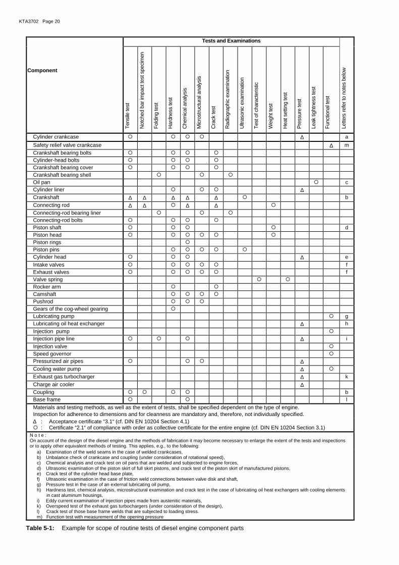
KTA3702 Page 20
Tests and Examinations
Component
Ten
sile
test
Not
ched
bar
impa
ct te
st s
peci
men
Fol
ding
test
Har
dnes
s te
st
Che
mic
al a
naly
sis
Mic
rost
ruct
ural
ana
lysi
s
Cra
ck te
st
Rad
iogr
aphi
c ex
amin
atio
n
Ultr
ason
ic e
xam
inat
ion
Tes
t of c
hara
cter
istic
Wei
ght t
est
Hea
t set
ting
test
Pre
ssur
e te
st
Leak
tigh
tnes
s te
st
Fun
ctio
nal t
est
Lette
rs re
fer t
o no
tes
belo
w
Cylinder crankcase � � � � ∆ a
Safety relief valve crankcase ∆ m Crankshaft bearing bolts � � � � Cylinder-head bolts � � � � Crankshaft bearing cover � � � � Crankshaft bearing shell � � � Oil pan � c Cylinder liner � � � ∆ Crankshaft ∆ ∆ ∆ ∆ ∆ � b
Connecting rod ∆ ∆ � ∆ ∆ � Connecting-rod bearing liner � � � Connecting-rod bolts � � � � Piston shaft � � � � d Piston head � � � � � � Piston rings � Piston pins � � � � � Cylinder head � � � ∆ e
Intake valves � � � � � f Exhaust valves � � � � � f Valve spring � � Rocker arm � � Camshaft � � � � Pushrod � � � Gears of the cog-wheel gearing � Lubricating pump � g Lubricating oil heat exchanger ∆ h Injection pump � Injection pipe line � � � ∆ i Injection valve � Speed governor � Pressurized air pipes � � � ∆ Cooling water pump ∆ � Exhaust gas turbocharger ∆ k
Charge air cooler ∆ Coupling � � � � b Base frame � � l
Materials and testing methods, as well as the extent of tests, shall be specified dependent on the type of engine. Inspection for adherence to dimensions and for cleanness are mandatory and, therefore, not individually specified. ∆ : Acceptance certificate “3.1“ (cf. DIN EN 10204 Section 4.1) � : Certificate “2.1“ of compliance with order as collective certificate for the entire engine (cf. DIN EN 10204 Section 3.1)
N o t e : On account of the design of the diesel engine and the methods of fabrication it may become necessary to enlarge the extent of the tests and inspections or to apply other equivalent methods of testing. This applies, e.g., to the following:
a) Examination of the weld seams in the case of welded crankcases, b) Unbalance check of crankcase and coupling (under consideration of rotational speed), c) Chemical analysis and crack test on oil pans that are welded and subjected to engine forces, d) Ultrasonic examination of the piston skirt of full skirt pistons, and crack test of the piston skirt of manufactured pistons, e) Crack test of the cylinder head base plate, f) Ultrasonic examination in the case of friction weld connections between valve disk and shaft, g) Pressure test in the case of an external lubricating oil pump, h) Hardness test, chemical analysis, microstructural examination and crack test in the case of lubricating oil heat exchangers with cooling elements
in cast aluminum housings, i) Eddy current examination of injection pipes made from austenitic materials, k) Overspeed test of the exhaust gas turbochargers (under consideration of the design), l) Crack test of those base frame welds that are subjected to loading stress. m) Function test with measurement of the opening pressure
Table 5-1: Example for scope of routine tests of diesel engine component parts
KTA 3702 Page 21
1 Specification of the Operating Media
1.1 Fuel ....................................................
1.2 Lubricating oil ....................................................
1.3 Coolant .................................................... 2 On-site Operating Conditions 2.1 Intake air temperature upstream of engine .............................................. °C
2.2 Coolant temperature downstream of engine .............................................. °C
2.3 Charge-air coolant temperature upstream of cooler .............................................. °C
2.4 Altitude of site above mean sea level ............................................... m
2.5 Intake pressure loss upstream of exhaust turbocharger 1) .............................................. Pa
2.6 Exhaust gas pressure downstream of exhaust turbocharger 1) .............................................. Pa
2.7 Fuel temperature upstream of engine .............................................. °C 3 Operating Power (at conditions as under No. 2) 3.1 Rated continuous power ................ kW at .......... RPM
3.2 Overload capacity (blocked output) ................ kW at .......... RPM 4 Reduction of operating power (effective braking power) 4.1 2 h P ................. kW ................ RPM
4.2 Full-load governor test 4.3 1 h P 110 % load
4.4 15 min P 75 % load
4.5 15 min P 50 % load
4.6 15 min P 25 % load
4.7 15 min P 10 % load
5 Measurements
Measurements and findings shall be registered in the test record. Operating values shall be read from the displays and recorded after 30 min, 60 min or at the end of the individual operating level. The lubricating oil consumption shall be determined during the test under item 4.1.
6 Functional Tests
6.1 Six startup cycles Startup pressure ........................................ MPa
Tank volume ............................................... l
Mean compressed air consumption per startup cycle ............................................... l
6.2 Overspeed limiter
6.3 Coastdown of exhaust gas turbocharger
6.4 Safety shutdown of oil pressure
6.5 Test of speed governor, determination of static change of speed (P-degree) and test of the speed adjustment device
6.6 Test of the attached electrical devices
6.7 Leak tightness test 7 Certification of Tests and Inspections: The tests and inspections shall be certified by the manufacturer in an ac-
ceptance test record.
1) The specified position of the throttle device shall be maintained during the entire acceptance test.
Table 5-2: Acceptance test of the diesel engine
At a fixed position of controls for 100 % load as under No. 3.1 and for nominal rotational speed
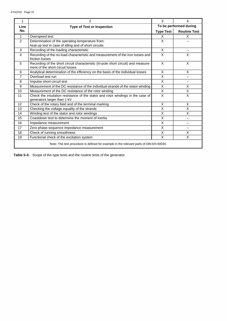
KTA3702 Page 22
1 2 3 4
Line No.
Type of Test or Inspection To be performed during
Type Test Routine Test 1 Overspeed test X X 2 Determination of the operating temperature from:
heat-up test in case of idling and of short circuits X −
3 Recording of the loading characteristic X − 4 Recording of the no-load characteristic and measurement of the iron losses and
friction losses X X
5 Recording of the short circuit characteristic (tri-pole short circuit) and measure-ment of the short circuit losses
X X
6 Analytical determination of the efficiency on the basis of the individual losses X X 7 Overload test run X − 8 Impulse short-circuit test X − 9 Measurement of the DC resistance of the individual strands of the stator winding X X 10 Measurement of the DC resistance of the rotor winding X X 11 Check the insulation resistance of the stator and rotor windings in the case of
generators larger than 1 kV X X
12 Check of the rotary field and of the terminal marking X X 13 Checking the voltage equality of the strands X X 14 Winding test of the stator and rotor windings X X 15 Coastdown test to determine the moment of inertia X − 16 Impedance measurement X − 17 Zero phase-sequence impedance measurement X − 18 Check of running smoothness X X 19 Functional check of the excitation system X X
Note: The test procedure is defined for example in the relevant parts of DIN EN 60034.
Table 5-3: Scope of the type tests and the routine tests of the generator
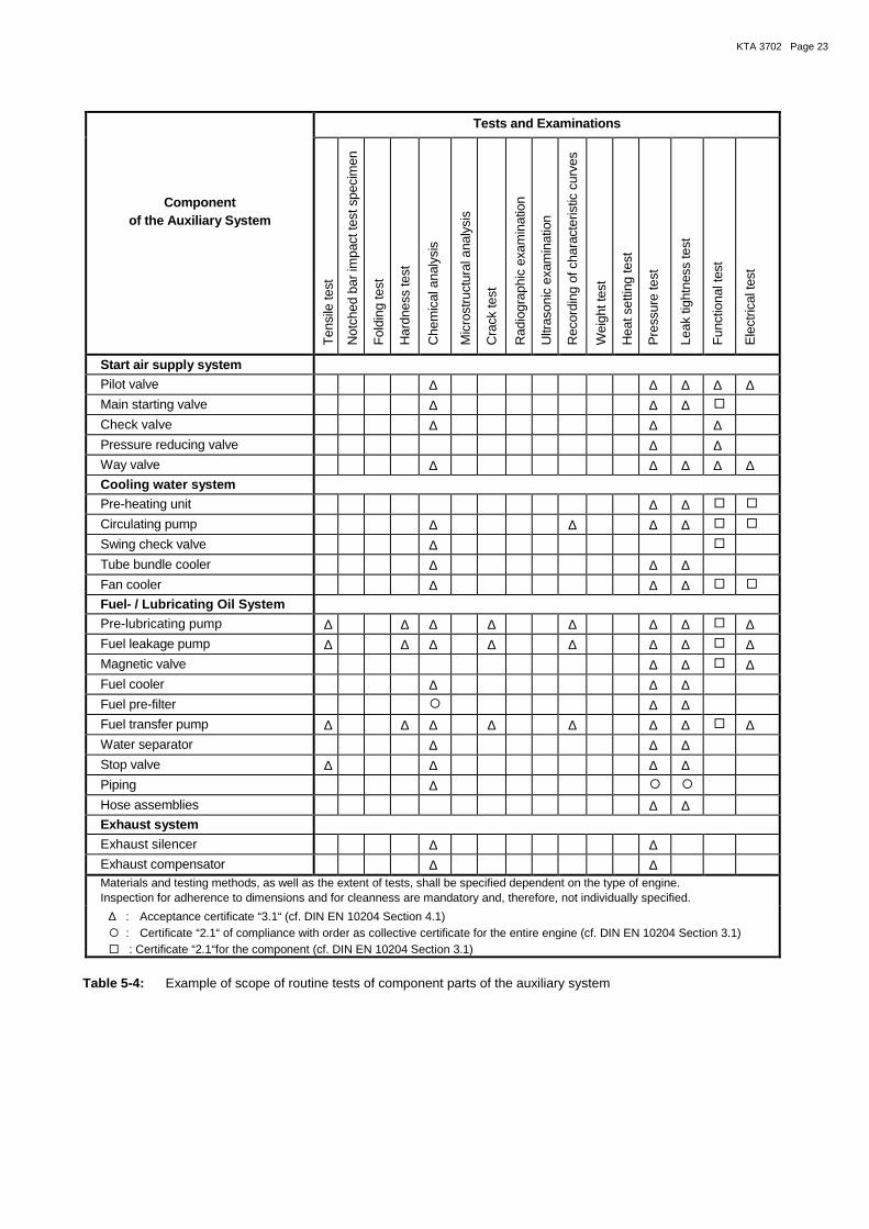
KTA 3702 Page 23
Tests and Examinations
Component of the Auxiliary System
Ten
sile
test
Not
ched
bar
impa
ct te
st s
peci
men
Fol
ding
test
Har
dnes
s te
st
Che
mic
al a
naly
sis
Mic
rost
ruct
ural
ana
lysi
s
Cra
ck te
st
Rad
iogr
aphi
c ex
amin
atio
n
Ultr
ason
ic e
xam
inat
ion
Rec
ordi
ng o
f cha
ract
eris
tic c
urve
s
Wei
ght t
est
Hea
t set
ting
test
Pre
ssur
e te
st
Leak
tigh
tnes
s te
st
Fun
ctio
nal t
est
Ele
ctric
al te
st
Start air supply system
Pilot valve ∆ ∆ ∆ ∆ ∆
Main starting valve ∆ ∆ ∆ �
Check valve ∆ ∆ ∆
Pressure reducing valve ∆ ∆
Way valve ∆ ∆ ∆ ∆ ∆ Cooling water system
Pre-heating unit ∆ ∆ � �
Circulating pump ∆ ∆ ∆ ∆ � �
Swing check valve ∆ �
Tube bundle cooler ∆ ∆ ∆
Fan cooler ∆ ∆ ∆ � �
Fuel- / Lubricating Oil System
Pre-lubricating pump ∆ ∆ ∆ ∆ ∆ ∆ ∆ � ∆
Fuel leakage pump ∆ ∆ ∆ ∆ ∆ ∆ ∆ � ∆
Magnetic valve ∆ ∆ � ∆
Fuel cooler ∆ ∆ ∆
Fuel pre-filter � ∆ ∆
Fuel transfer pump ∆ ∆ ∆ ∆ ∆ ∆ ∆ � ∆
Water separator ∆ ∆ ∆
Stop valve ∆ ∆ ∆ ∆
Piping ∆ � �
Hose assemblies ∆ ∆
Exhaust system
Exhaust silencer ∆ ∆
Exhaust compensator ∆ ∆ Materials and testing methods, as well as the extent of tests, shall be specified dependent on the type of engine. Inspection for adherence to dimensions and for cleanness are mandatory and, therefore, not individually specified.
∆ : Acceptance certificate “3.1“ (cf. DIN EN 10204 Section 4.1) � : Certificate “2.1“ of compliance with order as collective certificate for the entire engine (cf. DIN EN 10204 Section 3.1) � : Certificate “2.1“for the component (cf. DIN EN 10204 Section 3.1)
Table 5-4: Example of scope of routine tests of component parts of the auxiliary system
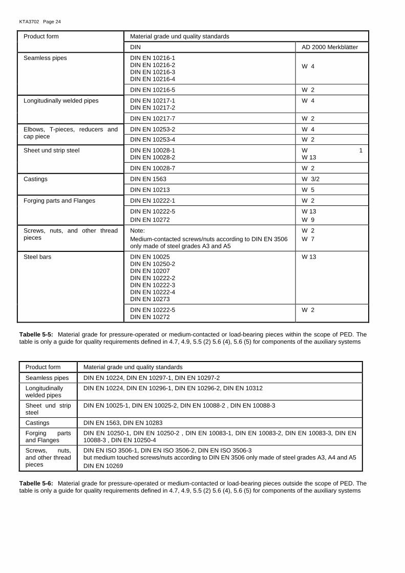
KTA3702 Page 24
Tabelle 5-5: Material grade for pressure-operated or medium-contacted or load-bearing pieces within the scope of PED. The table is only a guide for quality requirements defined in 4.7, 4.9, 5.5 (2) 5.6 (4), 5.6 (5) for components of the auxiliary systems
Product form Material grade und quality standards
Seamless pipes DIN EN 10224, DIN EN 10297-1, DIN EN 10297-2
Longitudinally welded pipes
DIN EN 10224, DIN EN 10296-1, DIN EN 10296-2, DIN EN 10312
Sheet und strip steel
DIN EN 10025-1, DIN EN 10025-2, DIN EN 10088-2 , DIN EN 10088-3
Castings DIN EN 1563, DIN EN 10283
Forging parts and Flanges
DIN EN 10250-1, DIN EN 10250-2 , DIN EN 10083-1, DIN EN 10083-2, DIN EN 10083-3, DIN EN 10088-3 , DIN EN 10250-4
Screws, nuts, and other thread pieces
DIN EN ISO 3506-1, DIN EN ISO 3506-2, DIN EN ISO 3506-3 but medium touched screws/nuts according to DIN EN 3506 only made of steel grades A3, A4 and A5 DIN EN 10269
Tabelle 5-6: Material grade for pressure-operated or medium-contacted or load-bearing pieces outside the scope of PED. The table is only a guide for quality requirements defined in 4.7, 4.9, 5.5 (2) 5.6 (4), 5.6 (5) for components of the auxiliary systems
Product form Material grade und quality standards
DIN AD 2000 Merkblätter
Seamless pipes DIN EN 10216-1 DIN EN 10216-2 DIN EN 10216-3 DIN EN 10216-4
W 4
DIN EN 10216-5 W 2
Longitudinally welded pipes DIN EN 10217-1 DIN EN 10217-2
W 4
DIN EN 10217-7 W 2
Elbows, T-pieces, reducers and cap piece
DIN EN 10253-2 W 4
DIN EN 10253-4 W 2
Sheet und strip steel DIN EN 10028-1 DIN EN 10028-2
W 1 W 13
DIN EN 10028-7 W 2
Castings DIN EN 1563 W 3/2
DIN EN 10213 W 5
Forging parts and Flanges
DIN EN 10222-1 W 2
DIN EN 10222-5 DIN EN 10272
W 13 W 9
Screws, nuts, and other thread pieces
Note: Medium-contacted screws/nuts according to DIN EN 3506 only made of steel grades A3 and A5
W 2 W 7
Steel bars DIN EN 10025 DIN EN 10250-2 DIN EN 10207 DIN EN 10222-2 DIN EN 10222-3 DIN EN 10222-4 DIN EN 10273
W 13
DIN EN 10222-5 DIN EN 10272
W 2
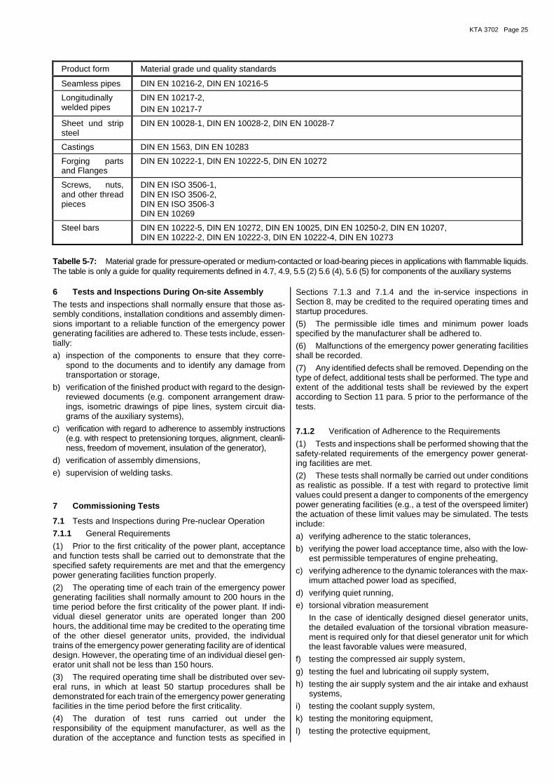
KTA 3702 Page 25
Product form Material grade und quality standards
Seamless pipes DIN EN 10216-2, DIN EN 10216-5
Longitudinally welded pipes
DIN EN 10217-2, DIN EN 10217-7
Sheet und strip steel
DIN EN 10028-1, DIN EN 10028-2, DIN EN 10028-7
Castings DIN EN 1563, DIN EN 10283
Forging parts and Flanges
DIN EN 10222-1, DIN EN 10222-5, DIN EN 10272
Screws, nuts, and other thread pieces
DIN EN ISO 3506-1, DIN EN ISO 3506-2, DIN EN ISO 3506-3 DIN EN 10269
Steel bars DIN EN 10222-5, DIN EN 10272, DIN EN 10025, DIN EN 10250-2, DIN EN 10207, DIN EN 10222-2, DIN EN 10222-3, DIN EN 10222-4, DIN EN 10273
Tabelle 5-7: Material grade for pressure-operated or medium-contacted or load-bearing pieces in applications with flammable liquids. The table is only a guide for quality requirements defined in 4.7, 4.9, 5.5 (2) 5.6 (4), 5.6 (5) for components of the auxiliary systems
6 Tests and Inspections During On-site Assembly
The tests and inspections shall normally ensure that those as-sembly conditions, installation conditions and assembly dimen-sions important to a reliable function of the emergency power generating facilities are adhered to. These tests include, essen-tially:
a) inspection of the components to ensure that they corre-spond to the documents and to identify any damage from transportation or storage,
b) verification of the finished product with regard to the design-reviewed documents (e.g. component arrangement draw-ings, isometric drawings of pipe lines, system circuit dia-grams of the auxiliary systems),
c) verification with regard to adherence to assembly instructions (e.g. with respect to pretensioning torques, alignment, cleanli-ness, freedom of movement, insulation of the generator),
d) verification of assembly dimensions,
e) supervision of welding tasks.
7 Commissioning Tests
7.1 Tests and Inspections during Pre-nuclear Operation
7.1.1 General Requirements
(1) Prior to the first criticality of the power plant, acceptance and function tests shall be carried out to demonstrate that the specified safety requirements are met and that the emergency power generating facilities function properly.
(2) The operating time of each train of the emergency power generating facilities shall normally amount to 200 hours in the time period before the first criticality of the power plant. If indi-vidual diesel generator units are operated longer than 200 hours, the additional time may be credited to the operating time of the other diesel generator units, provided, the individual trains of the emergency power generating facility are of identical design. However, the operating time of an individual diesel gen-erator unit shall not be less than 150 hours.
(3) The required operating time shall be distributed over sev-eral runs, in which at least 50 startup procedures shall be demonstrated for each train of the emergency power generating facilities in the time period before the first criticality.
(4) The duration of test runs carried out under the responsibility of the equipment manufacturer, as well as the duration of the acceptance and function tests as specified in
Sections 7.1.3 and 7.1.4 and the in-service inspections in Section 8, may be credited to the required operating times and startup procedures.
(5) The permissible idle times and minimum power loads specified by the manufacturer shall be adhered to.
(6) Malfunctions of the emergency power generating facilities shall be recorded.
(7) Any identified defects shall be removed. Depending on the type of defect, additional tests shall be performed. The type and extent of the additional tests shall be reviewed by the expert according to Section 11 para. 5 prior to the performance of the tests.
7.1.2 Verification of Adherence to the Requirements
(1) Tests and inspections shall be performed showing that the safety-related requirements of the emergency power generat-ing facilities are met.
(2) These tests shall normally be carried out under conditions as realistic as possible. If a test with regard to protective limit values could present a danger to components of the emergency power generating facilities (e.g., a test of the overspeed limiter) the actuation of these limit values may be simulated. The tests include:
a) verifying adherence to the static tolerances,
b) verifying the power load acceptance time, also with the low-est permissible temperatures of engine preheating,
c) verifying adherence to the dynamic tolerances with the max-imum attached power load as specified,
d) verifying quiet running,
e) torsional vibration measurement
In the case of identically designed diesel generator units, the detailed evaluation of the torsional vibration measure-ment is required only for that diesel generator unit for which the least favorable values were measured,
f) testing the compressed air supply system,
g) testing the fuel and lubricating oil supply system,
h) testing the air supply system and the air intake and exhaust systems,
i) testing the coolant supply system,
k) testing the monitoring equipment,
l) testing the protective equipment,

KTA3702 Page 26
p) testing the sound level at the diesel control station compart-ment,
q) testing the possibilities for manual actions, the synchroniza-tion, the reconnection of the emergency power supply system to the station service equipment from the local control station,
r) testing the interlocks,
s) testing the insulation of the generator bearing.
7.1.3 Power Load Operation of the Diesel Generator Units
(1) Within the operating time of each emergency power gen-erating facility as specified in Section 7.1.1, the diesel generator unit shall be subjected to at least one uninterrupted power load operation of minimum 24 hours. This shall include at least six hours at the rated continuous power and one hour at overload power capacity. For one of a number of design-identical diesel generator units, this power load operation run shall be extended to 72 hours. The displays of safety-related measurement values shall be read and recorded.
(2) During these power load operation runs, special attention shall be paid to checking the cooling of the diesel engine and generator as well as the adequacy of the design of the internal and external cooling circuits.
7.1.4 Preliminary Emergency Power Tests
Preliminary emergency power tests shall be carried out to demonstrate the functional capability of the individual emer-gency power trains as well as the entire emergency power sys-tem. For these tests, all systems to be supplied by the emer-gency power system shall normally be available to serve as power loads. At least the following tests shall be carried out:
a) startup and power loading of each train of the emergency power generating facility by triggering the respective reactor protection signals,
b) parallel net operation of one emergency power generating facility and disconnection of the power supply from the as-sociated train of the station service facility,
c) startup and power loading of all emergency power generat-ing facilities by a simultaneous disconnection of the power supplies from the station service facility,
d) verifying that the in-service inspections can be carried out under consideration of the reactor protection system and the process-technological systems.
7.2 Tests During Initial Nuclear Startup Operation
(1) An emergency power supply test shall be carried out within the framework of the initial nuclear startup operation. This test shall be performed during partial power load operation of the re-actor and shall be initiated by disconnecting the station service power supply. It shall be possible to operate the power plant for at least one hour under emergency power supply conditions.
(2) Prior to carrying out this emergency power supply test, all trains of the emergency power generating facilities shall nor-mally have been subjected to in-service inspections to demon-strated their functional capability. The test shall be initiated only if all power grid feed-ins are available.
(3) During the emergency power supply test, the power load-ing of the components of the emergency power supply system (e.g. emergency power units, transformers, rectifiers, convert-ers) shall normally be checked.
7.3 Tests After Modifications
After modifications, the restoration of operational availability shall be demonstrated by an examination. Depending on the type and extent of the parts or functions concerned, the test scope shall be specified in agreement with the proper nuclear
authority or an authorized expert appointed under Section 20 AtG by this authority.
8 In-service Inspections
8.1 General Requirements
(1) In-service inspections shall be carried out to verify the continued functional capability of the emergency power gener-ating facilities. These tests are normally not be carried out sim-ultaneously in several trains.
(2) In the case of a startup failure or failure during a test run, the test run shall be repeated, following the identification of the cause and removal of the defect. If the cause cannot be clearly identified, a new test interval shall be specified as agreed upon with the expert according to Section 11 para. 5.
(3) Visual inspections of the emergency power generating fa-cilities shall be carried out during the test runs specified in Sec-tions 8.2 and 8.3.
8.2 Function Test Run
(1) The function test run shall include startup and power loading of the emergency power generating facility with a sub-sequent power load operation run in parallel net operation. The total duration of the test run shall normally be two hours. At the end of the test run during parallel net operation, the diesel generator unit shall normally be power loaded to at least 80 % of the rated continuous power for the duration of at least one hour.
(2) The function test run shall normally be performed in in-tervals of four weeks on each emergency power generating facility as well as prior to every startup of the power plant fol-lowing a longer outage (e.g. refueling). The function test runs of redundant emergency power generating facilities shall nor-mally be distributed evenly over the test interval (e.g. one test run of one train every week in case of a four-train emergency power generating facility). It is permissible to extend the test intervals, provided the extension is well-founded on operating experience.
(3) Triggering the startup and power loading program shall normally be effected by simulating the startup criterion. During these tests, all the protective equipment of the emergency power generating facilities shall normally be effective.
(4) Startup shall be triggered at least once a year by discon-necting the bus coupler between station service equipment and diesel generator bus.
(5) An insular operation shall subsequently be followed by a parallel-net operation.
(6) The execution of the commands issued by the startup and power loading program and the time sequence shall be rec-orded automatically and shall be verified with respect to any de-viations from the specified times.
8.3 Test Run at Overload Power Capacity
Once every 12 months after a function test run as specified in Section 8.2 para. 1, each diesel generator unit shall be operated at overload power capacity for at least 30 minutes (e.g. one function test run of one train every three months in the case of a four-train diesel generator facility).
8.4 72-h-test run
Within 8 years an endurance test of at least 72 h shall be per-formed in accordance with a plant-specific load profile on all emergency diesel generators (incl. combined emergency feed-water and diesel generators).

KTA 3702 Page 27
8.5 Testing the Instrumentation and Control Equipment
(1) Instrumentation and control equipment shall be tested at regular intervals. The test intervals shall be coordinated with those of the other instrumentation and control equipment of the emergency power system. A test interval of four years shall nor-mally not be exceeded (e.g. each year one train of a four-train emergency power generating facilities is tested).
(2) The tests shall be simple to carry out using testing aids (e.g, test adapters, test sockets) without changing the wiring.
8.6 Examination of the Operating Media
8.6.1 Fuel
(1) The adherence to the specified requirements of the fuel and the changes it undergoes in the fuel storage tanks shall be checked on representative samples
a) during the initial filling,
b) following each refill or new filling,
c) in intervals of six months.
(2) The fuel in the operating and storage tanks shall be re-placed whenever the requirements for the fuel with respect to density, boiling behavior, viscosity, flash point, carbonization res-idues, ash content and water content are no longer met.
(3) In the case of replenishment or new filling of the fuel stor-age tanks, a material identification check shall be carried out upon fuel delivery and prior to filling the fuel; this check shall determine the following values:
a) visual evaluation (fuel shall be clear and free of solid impu-rities),
b) density,
c) flash point,
d) water content.
The fuel may only be in the fuel storage tanks if the require-ments regarding items a) through d) are met as specified.
(4) The fuel from the storage tanks shall be subjected to an aging test in yearly intervals. The original procedure shall re-peatedly be used for comparison purposes. The results shall be evaluated by the fuel manufacturer and the authorized expert (under Section 20 Atomic Energy Act) with respect to continued storage and usability of the fuel. The test interval shall be re-duced if necessary.
(5) Heating oil (extra light) shall normally be used as fuel only if the supplier can demonstrate that all requirements of this safety standard regarding diesel fuel are met. N o t e :
Diesel fuels with organic content (e.g. rapeseed methyl ester) can cause problems (high water content, gel formation, lower power den-sity, limited shelf life).
8.6.2 Lubricating Oil
(1) Upon delivery, adherence to the values specified by the component manufacturer shall be demonstrated, and a material identification check shall be carried out on each container.
(2) Analyses shall be carried out to determine whether or not an unscheduled oil change becomes necessary. These anal-yses include:
a) visual inspection for unusual water content prior to or during each test run,
b) half-yearly inspections in accordance with the regulations of the component manufacturer, however, at least for
ba) undissolved substances,
bb) viscosity,
bc) flash point,
bd) water content,
be) base number (TBN - total base number).
The samples shall be taken from the running engine before the end of a test run.
8.6.3 Coolant of the Internal Cooling Circuit
(1) When refilling, compliance with the specified values of the component manufacturer shall be demonstrated.
(2) The regular operational surveillance shall be carried out in accordance with the regulations of the engine manufacturer. At least the following tests shall be performed:
a) determination of the concentration of the coolant additive,
b) measurement of the pH index.
A test interval of six months shall not be exceeded. In case cor-rosion protection oils are used in the coolant, this test interval shall normally be reduced to four weeks. The samples shall be taken during the test run either from the provided sample removal location or from a pipe with a high through flow.
9 Operation, Servicing, and Repair
9.1 General Requirements
(1) The design and arrangement of all components in the emergency power generating facility shall normally allow a clear view, good maintenance and short repair time by providing e.g. good accessibility and interchangeability.
(2) Clear instructions shall be provided for operation, servic-ing and repair. The regulations of the respective manufacturer shall be adhered to.
(3) Malfunctions and damage shall be repaired without delay.
9.2 Operation of the Emergency Power Generating Facility
(1) One person shall be on duty during each shift who is qual-ified to carry out the following tasks:
a) inspection of operating emergency power generating facili-ties with respect to function and supply storage.
b) initiation of the detection and elimination of malfunctions and faults.
(2) The shut-down procedure of the emergency power gener-ating facilities shall normally be initiated manually, however, only when the following conditions are met:
a) A supply of the emergency power bus bars shall be availa-ble from a power feed-in that is independent of the emer-gency power generating facilities.
b) The coolant of the internal cooling circuit shall normally have reached the equilibrium temperature.
(3) The shut-down procedure shall be carried out separately for each train.
(4) The idle time specified by the manufacturer for the diesel engine shall normally not be exceeded.
(5) After the maximum continuous operating time specified for the diesel generator unit has been exceeded it shall be sub-jected to extended servicing in agreement with the manufac-turer.
9.3 Servicing and Repair
(1) The diesel generator unit and auxiliary systems (e.g., cool-ers, pumps, compressors, tanks) shall be serviced in accord-ance with a written servicing schedule. In preparing the servic-ing schedule, the following shall be taken into account:
a) the safety requirements of the nuclear power plant,
b) the permissible times of non-availability of the emergency power generating facilities for servicing tasks,
KTA3702 Page 28
c) the time sequence of the servicing of the individual trains of the emergency power generating facilities,
d) the servicing schedules of the component manufacturers,
e) the indications found in servicing comparable components.
(2) The fuel and lubricating oil storage tanks shall normally be drained of water once a year and shall be cleaned internally once every five years.
(3) The lubricating oil shall be changed in accordance with the regulations of the engine manufacturer. If the lubricating oil is not changed for a period longer than one year, the lubricating oil shall be subjected to tests regarding its quality that, in agree-ment with the engine manufacturer, are more extensive than specified in Section 8.5.2 para. 2 item b.
(4) Those parts listed in Tables 5-1, 5-3 and 5-4 that are re-placed in the course of maintenance shall be subjected to doc-umented tests as specified in Sections 5.2, 5.4, 5.6, 5.8 and 6.
(5) Those parts listed in Tables 5-1, 5-3 and 5-4 that are re-placed in the course of maintenance and are modified with re-spect to the original configuration shall be subjected to docu-mented suitability tests and routine tests.
(6) If there are any indications of systematic errors that lead to functional impairments of components, the cause must be eliminated or further procedures agreed upon with the proper nuclear authority or an authorized expert appointed under Sec-tion 20 AtG by this authority.
(7) Those parts listed in Tables 5-1, 5-3 and 5-4 that are over-hauled in the course of maintenance shall be subjected to tests, the extent of which shall be specified on an individual basis.
10 Tests Subsequent to Servicing or Repair
(1) After completion of servicing or repair tasks that have led to an interruption of functional operability, the restoration to op-erability shall be demonstrated by means of a test. Depending on the scope and type of the parts or functions concerned, the test scopes shall be specified in agreement with the proper nu-clear authority or an authorized expert appointed under Sec-tion 20 AtG by this authority.
(2) After an interruption of functional operability resulting from servicing or repair, at least one function test run as specified in Section 8.2 shall be performed.
(3) After a basic overhaul of a diesel engine, an endurance test in accordance with 8.4 shall be carried out on the facility for at least 72 hours.
11 Testers
(1) The type tests as specified in Sections 5.1 and 5.3 shall normally be carried out by plant experts of the manufacturer or under their responsibility. Furthermore, an expert shall participate who meets the requirements of impartiality, suitabil-ity, reliability (in accordance with § 12 of the Atomic Energy Act) or who is a member of an IACS classification society.
(2) The suitability test according to Section 3.6, 5.5 and 5.7 shall be carried out with the participation of an expert who meets the requirements of impartiality, suitability, reliability (in accordance with § 12 of the Atomic Energy Act).
(3) The plant-specific suitability check shall be carried out by the nuclear authority or by an expert appointed by that nuclear authority in accordance with §20 Atomic Energy Act proce-dures.
(4) The routine test as specified in Sections 5.2, 5.4, 5.6 and 5.8 shall normally be carried out by plant experts of the manu-facturer or under their responsibility. The proper nuclear author-ity or an authorized expert appointed under Section 20 AtG by this authority shall be consulted.
(5) The tests and inspections during on-site assembly as spec-ified in Section 6, the commissioning tests in Section 7, the in-service inspections under Section 8 and the tests subsequent to servicing and repair as specified in Section 10 shall be carried out by competent personnel specified by the licensee. The proper nuclear authority or an authorized expert appointed in Section 20 AtG by this authority shall be consulted.
12 Test Certification and Documentation
(1) All tests carried out in accordance with this safety stand-ard shall be certified. The test certifications shall contain the in-formation necessary for the assessment and evaluation of the tests. This includes information on:
a) testing organization,
b) test object,
c) test extent,
d) type of test,
e) identification number of the testing instruction and, if appli-cable, also of the standard testing instruction,
f) testing procedure (required and actual date of the test),
g) test results,
h) confirmation of test performance, their results and evalua-tion by the signature of the testers and, if participation was required, of the proper nuclear authority or of an authorized expert appointed under Section 20 AtG by this authority.
(2) The servicing and repair as specified in Section 9.3 shall be documented.
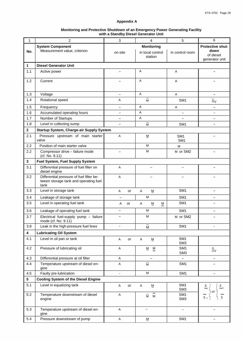
KTA 3702 Page 29
Appendix A
Monitoring and Protective Shutdown of an Emergency Power Generating Facility with a Standby Diesel Generator Unit
1 2 3 4 5 6
No.
System Component Measurement value, criterion
Monitoring Protective shut-down
of diesel generator unit
on-site in local control station
in control room
1 Diesel Generator Unit
1.1 Active power − A A
−
1.2 Current − A
A
−
1.3 Voltage − A A −
1.4 Rotational speed A M SM1 VS
1.5 Frequency − A A −
1.6 Accumulated operating hours − A − −
1.7 Number of Startups − A − − 1.8 Level in collecting sump − M SM1 −
2 Startup System, Charge-air Supply System
2.1 Pressure upstream of main starter valve
A M SM1 SM1
−
2.2 Position of main starter valve M M
2.2 Compressor drive – failure mode (cf. No. 9.11)
− M M or SM2 −
3 Fuel System, Fuel Supply System
3.1 Differential pressure of fuel filter on diesel engine
A − − −
3.2 Differential pressure of fuel filter be-tween storage tank and operating fuel tank
A − − −
3.3 Level in storage tank A or A M SM1 −
3.4 Leakage of storage tank − M SM1 −
3.5 Level in operating fuel tank A or A M M SM1 −
3.6 Leakage of operating fuel tank − M SM1 −
3.7 Electrical fuel-supply pump – failure mode (cf. No. 9.11)
− M M or SM2 −
3.8 Leak in the high-pressure fuel lines - M SM1 -
4 Lubricating Oil System
4.1 Level in oil pan or tank A or A M SM1 SM3
4.2 Pressure of lubricating oil A M M SM1 SM3
VS
4.3 Differential pressure at oil filter A − − −
4.4 Temperature upstream of diesel en-gine
A M SM1 −
4.5 Faulty pre-lubrication - M SM1 −
5 Cooling System of the Diesel Engine
5.1 Level in equalizing tank A or A M SM1 SM3
S
S
or
S
SV
V
5.2 Temperature downstream of diesel
engine A M M SM1
SM3
5.3 Temperature upstream of diesel en-gine
A − − −
5.4 Pressure downstream of pump A M SM1 −
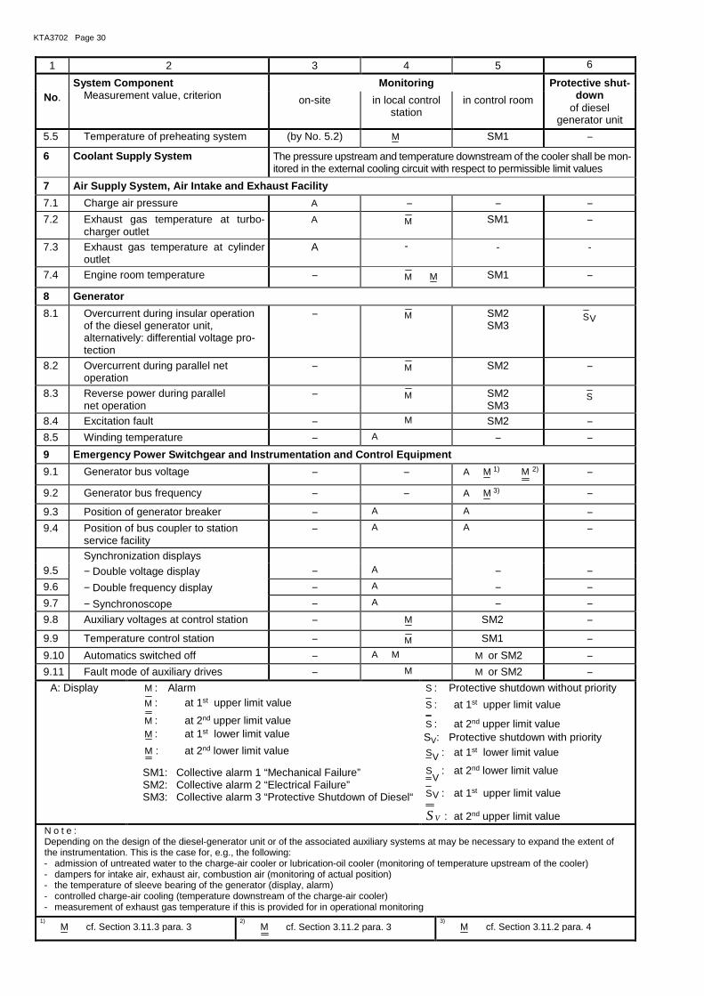
KTA3702 Page 30
1 2 3 4 5 6
No.
System Component Measurement value, criterion
Monitoring Protective shut-down
of diesel generator unit
on-site in local control station
in control room
5.5 Temperature of preheating system (by No. 5.2) M SM1 −
6 Coolant Supply System The pressure upstream and temperature downstream of the cooler shall be mon-itored in the external cooling circuit with respect to permissible limit values
7 Air Supply System, Air Intake and Exhaust Facility
7.1 Charge air pressure A − − −
7.2 Exhaust gas temperature at turbo-charger outlet
A M SM1 −
7.3 Exhaust gas temperature at cylinder outlet
A - - -
7.4 Engine room temperature − M M SM1 −
8 Generator
8.1 Overcurrent during insular operation of the diesel generator unit, alternatively: differential voltage pro-tection
− M SM2 SM3
VS
8.2 Overcurrent during parallel net operation
− M SM2 −
8.3 Reverse power during parallel net operation
− M SM2 SM3
S
8.4 Excitation fault − M SM2 −
8.5 Winding temperature − A − −
9 Emergency Power Switchgear and Instrumentation and Control Equipment
9.1 Generator bus voltage − − A M 1) M 2) −
9.2 Generator bus frequency − − A M 3) −
9.3 Position of generator breaker − A A −
9.4 Position of bus coupler to station service facility
− A A −
Synchronization displays 9.5 − Double voltage display − A − −
9.6 − Double frequency display − A − −
9.7 − Synchronoscope − A − −
9.8 Auxiliary voltages at control station − M SM2 −
9.9 Temperature control station − M SM1 −
9.10 Automatics switched off − A M M or SM2 −
9.11 Fault mode of auxiliary drives − M M or SM2 − A: Display M : Alarm
M : at 1st upper limit value
M : at 2nd upper limit value M : at 1st lower limit value
M : at 2nd lower limit value
SM1: Collective alarm 1 “Mechanical Failure” SM2: Collective alarm 2 “Electrical Failure” SM3: Collective alarm 3 “Protective Shutdown of Diesel“
S : Protective shutdown without priority
S : at 1st upper limit value
S : at 2nd upper limit value SV: Protective shutdown with priority
VS : at 1st lower limit value
VS : at 2nd lower limit value
VS : at 1st upper limit value
VS : at 2nd upper limit value N o t e : Depending on the design of the diesel-generator unit or of the associated auxiliary systems at may be necessary to expand the extent of the instrumentation. This is the case for, e.g., the following: - admission of untreated water to the charge-air cooler or lubrication-oil cooler (monitoring of temperature upstream of the cooler) - dampers for intake air, exhaust air, combustion air (monitoring of actual position) - the temperature of sleeve bearing of the generator (display, alarm) - controlled charge-air cooling (temperature downstream of the charge-air cooler) - measurement of exhaust gas temperature if this is provided for in operational monitoring
1) M cf. Section 3.11.3 para. 3 2) M cf. Section 3.11.2 para. 3
3) M cf. Section 3.11.2 para. 4
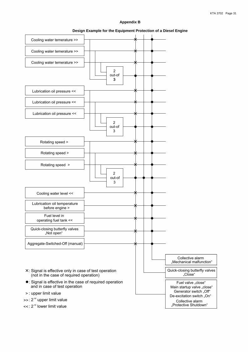
KTA 3702 Page 31
Appendix B
Design Example for the Equipment Protection of a Diesel Engine
2
2
2
De-excitation switch On„ “
Fuel valve close„ “
„ “Close
Collective alarm
Quick-closing butterfly valves
„Mechan “ical malfunctionCollective alarm
Generator switch Off„ “
„ “Protective Shutdown
Main startup valve close„ “
Rotating speed >
Rotating speed >
Rotating speed >
Lubrication oil pressure <<
Lubrication oil pressure <<
Lubrication oil pressure <<
Cooling water temerature >>
Cooling water temerature >>
Cooling water temerature >>
Aggregat - ( )e Switched-Off manual
„ “Not openQuick-closing butterfly valves
operating fuel tank <<
Fuel level in
before engine >Lubrication oil temperature
Cooling water level <<
>>
<<
>
: Signal is effective in the case of required operation
: 2nd
upper limit value
: Signal is effective only in case of test operation
: upper limit value
: 2nd
lower limit value
a in case of test operationnd
(n )ot in the case of required operation
out-of
3
out-of3
3
out-of
3
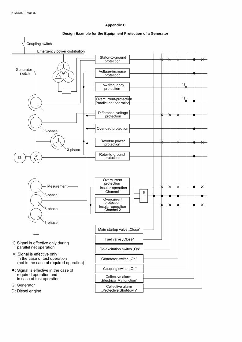
KTA3702 Page 32
Appendix C
Design Example for the Equipment Protection of a Generator
GD
3
&
Coupling switch
Emergency power distribution
3-phase
3-phase
3-phase
3-phase
Mesurement
3-phase
Rotor-to-ground
Coupling switch On„ “
Reverse power
Overload protection
Differential voltage
Parallel net operationOvercurrent-protection
Low frequency
protectionVoltage-increase
protectionStator-to-ground
„Ele tri “c cal Malfunction
Collective alarm
Generator „ “switch On
De-excitation switch On„ “
Fuel valve Close„ “
Main startup valve Close„ “
Collective alarm
„ “Protective Shutdown
Insular-operation
Overcurrent
1)
1)
switchGenerator
G
1)
D
: Generator
: Signal is effective only
: Diesel engine
: Signal is effective in the case of
Signal is effective only during
required operation and
in the case of test operation
parallel net operation
protection
protection
protection
protection
protection
Channel 1
Overcurrentprotection
Insular-operationChannel 2
(not in the case of required operation)
in case of test operation

KTA 3702 Page 33
Appendix D
Type Testing of a Diesel Engine
D 1 Documents to be Submitted
(1) The following documents shall be submitted:
a) technical drawings
aa) assembly drawing showing the main dimensions (length, width, and height) with respect to the crank-shaft axis,
ab) longitudinal section and cross section for the engine series,
b) technical data as listed in Table 4-1,
c) system layout diagrams and a summary description of the auxiliary systems of the diesel engine involved in the tests, including the demarcation regarding which components are part of the engine and which part of the test bench
ca) lubricating oil system,
cb) fuel system,
cc) cooling system,
cd) combustion air supply and exhaust system,
ce) startup system,
cf) diagram of measurement locations.
(2) The essential component parts of the diesel engine, which are included in the extent of the type test, shall be documented. This documentation shall make it possible to determine whether or not these component parts are similar to those of the diesel engine used in the nuclear power plant.
D 2 Measurement and Verification Tasks
D 2.1 Tasks Before the Test Run
Prior to the test run, the following checks and tests shall be car-ried out:
a) verification that measurement locations and their numbers are in agreement with those in the measurement location overview, in the measurement location list and the measu-rement record,
b) verification of the measurement equipment with respect to applicability and display accuracy as specified in Sec-tion D 2.6 paras. 2 and 3,
c) verification of the dynamometric brake as specified in Sec-tion D 2.6 para. 4,
d) taking a sample from the fuel, lubricating oil and coolant as specified in Section D 2.5,
e) recording of the lubricating oil level at the beginning of the 100 hour test run (cf. Section D 2 4.3).
D 2.2 Tasks During the Test Run
The following tasks shall be carried out during the test run:
a) measurements and calculations as listed in Table D-1 and their documentation.
b) continuous measurements during the test run as specified in Section D 2.6 para. 5,
c) taking of samples from the lubricating oil and coolant prior to the end of the test run.
D 2.3 Tasks after Ending the Test-Run
The following tasks shall be carried out after ending the test run:
a) inspection regarding general condition, cleanness and leak tightness,
b) recording of the lubricating oil level and calculation of the consumption as specified in Section D 2.4.3,
c) disassembly of the engine for visual inspection,
d) visual inspection of the engine components as specified in Section D 4.
D 2.4 Boundary Conditions for the Measurements
D 2.4.1 Measurement of the Power Rating
(1) The diesel engine shall be operated on the basis of actual power ratings; it is not permissible to apply conversion formu-las.
(2) The temperatures of the intake air and the charge-air cool-ing water shall not exceed a tolerance of ± 2 K in the steady state.
(3) The throttle devices shall be adjusted such that, at the rated continuous power and nominal speed, the maximum val-ues of intake pressure loss and exhaust gas back pressure for the specified reference condition are attained. This adjustment of the throttle device position shall be maintained during the en-tire test run.
D 2.4.2 Measurement of Fuel Consumption
The fuel consumption shall be measured only when constant operating values (pressure and temperature) are reached.
D 2.4.3 Measurement of Lubricating Oil Consumption
The method for measuring the lubricating oil consumption shall be specified taking the type of lubricating oil system into ac-count. The oil level readings before and after the test run shall be performed under similar boundary conditions. The oil amounts replenished during the test run shall be noted in the measurement record.
D 2.5 Analysis of the Operating Media
(1) Samples of the fuel, lubricating oil and coolant shall be re-moved from the running engine and shall be marked and sealed in the presence of the expert according to Section 11 para. 1.
(2) Two samples shall be removed in each case. The first sample shall be analyzed and the second sample shall be kept until the results of this analysis are available. The results shall be included in the test report.
(3) On the basis of the samples taken prior to the beginning of the test run and at each fuel replenishment, the engine man-ufacturer shall demonstrate that the fuel provided is in accord-ance with his own regulations.
D 2.6 Measurement Instruments and recording devices
(1) All measurement instruments and recording devices shall be compiled in a list and numbered in correspondence with the measurement location list. The list shall permit the subsequent identification of the measurement instruments and recording de-vices used and shall include information on the detection meth-ods and processing of the measured values.
(2) For all employed measurement instruments calibration certificates shall be submitted.
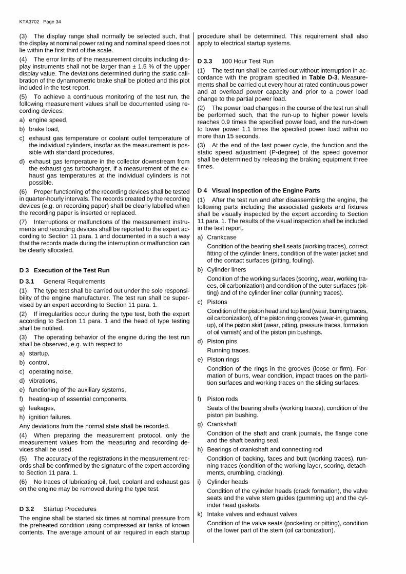
KTA3702 Page 34
(3) The display range shall normally be selected such, that the display at nominal power rating and nominal speed does not lie within the first third of the scale.
(4) The error limits of the measurement circuits including dis-play instruments shall not be larger than ± 1.5 % of the upper display value. The deviations determined during the static cali-bration of the dynamometric brake shall be plotted and this plot included in the test report.
(5) To achieve a continuous monitoring of the test run, the following measurement values shall be documented using re-cording devices:
a) engine speed,
b) brake load,
c) exhaust gas temperature or coolant outlet temperature of the individual cylinders, insofar as the measurement is pos-sible with standard procedures,
d) exhaust gas temperature in the collector downstream from the exhaust gas turbocharger, if a measurement of the ex-haust gas temperatures at the individual cylinders is not possible.
(6) Proper functioning of the recording devices shall be tested in quarter-hourly intervals. The records created by the recording devices (e.g. on recording paper) shall be clearly labelled when the recording paper is inserted or replaced.
(7) Interruptions or malfunctions of the measurement instru-ments and recording devices shall be reported to the expert ac-cording to Section 11 para. 1 and documented in a such a way that the records made during the interruption or malfunction can be clearly allocated.
D 3 Execution of the Test Run
D 3.1 General Requirements
(1) The type test shall be carried out under the sole responsi-bility of the engine manufacturer. The test run shall be super-vised by an expert according to Section 11 para. 1.
(2) If irregularities occur during the type test, both the expert according to Section 11 para. 1 and the head of type testing shall be notified.
(3) The operating behavior of the engine during the test run shall be observed, e.g. with respect to
a) startup,
b) control,
c) operating noise,
d) vibrations,
e) functioning of the auxiliary systems,
f) heating-up of essential components,
g) leakages,
h) ignition failures.
Any deviations from the normal state shall be recorded.
(4) When preparing the measurement protocol, only the measurement values from the measuring and recording de-vices shall be used.
(5) The accuracy of the registrations in the measurement rec-ords shall be confirmed by the signature of the expert according to Section 11 para. 1.
(6) No traces of lubricating oil, fuel, coolant and exhaust gas on the engine may be removed during the type test.
D 3.2 Startup Procedures
The engine shall be started six times at nominal pressure from the preheated condition using compressed air tanks of known contents. The average amount of air required in each startup
procedure shall be determined. This requirement shall also apply to electrical startup systems.
D 3.3 100 Hour Test Run
(1) The test run shall be carried out without interruption in ac-cordance with the program specified in Table D-3. Measure-ments shall be carried out every hour at rated continuous power and at overload power capacity and prior to a power load change to the partial power load.
(2) The power load changes in the course of the test run shall be performed such, that the run-up to higher power levels reaches 0.9 times the specified power load, and the run-down to lower power 1.1 times the specified power load within no more than 15 seconds.
(3) At the end of the last power cycle, the function and the static speed adjustment (P-degree) of the speed governor shall be determined by releasing the braking equipment three times.
D 4 Visual Inspection of the Engine Parts
(1) After the test run and after disassembling the engine, the following parts including the associated gaskets and fixtures shall be visually inspected by the expert according to Section 11 para. 1. The results of the visual inspection shall be included in the test report.
a) Crankcase
Condition of the bearing shell seats (working traces), correct fitting of the cylinder liners, condition of the water jacket and of the contact surfaces (pitting, fouling).
b) Cylinder liners
Condition of the working surfaces (scoring, wear, working tra-ces, oil carbonization) and condition of the outer surfaces (pit-ting) and of the cylinder liner collar (running traces).
c) Pistons
Condition of the piston head and top land (wear, burning traces, oil carbonization), of the piston ring grooves (wear-in, gumming up), of the piston skirt (wear, pitting, pressure traces, formation of oil varnish) and of the piston pin bushings.
d) Piston pins
Running traces.
e) Piston rings
Condition of the rings in the grooves (loose or firm). For-mation of burrs, wear condition, impact traces on the parti-tion surfaces and working traces on the sliding surfaces.
f) Piston rods
Seats of the bearing shells (working traces), condition of the piston pin bushing.
g) Crankshaft
Condition of the shaft and crank journals, the flange cone and the shaft bearing seal.
h) Bearings of crankshaft and connecting rod
Condition of backing, faces and butt (working traces), run-ning traces (condition of the working layer, scoring, detach-ments, crumbling, cracking).
i) Cylinder heads
Condition of the cylinder heads (crack formation), the valve seats and the valve stem guides (gumming up) and the cyl-inder head gaskets.
k) Intake valves and exhaust valves
Condition of the valve seats (pocketing or pitting), condition of the lower part of the stem (oil carbonization).
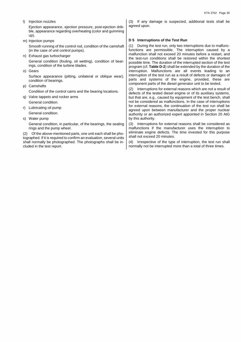
KTA 3702 Page 35
l) Injection nozzles
Ejection appearance, ejection pressure, post-ejection drib-ble, appearance regarding overheating (color and gumming up).
m) Injection pumps
Smooth running of the control rod, condition of the camshaft (in the case of unit control pumps).
n) Exhaust gas turbocharger
General condition (fouling, oil wetting), condition of bear-ings, condition of the turbine blades.
o) Gears
Surface appearance (pitting, unilateral or oblique wear), condition of bearings.
p) Camshafts
Condition of the control cams and the bearing locations.
q) Valve tappets and rocker arms
General condition.
r) Lubricating oil pump
General condition.
s) Water pump
General condition, in particular, of the bearings, the sealing rings and the pump wheel.
(2) Of the above-mentioned parts, one unit each shall be pho-tographed. If it is required to confirm an evaluation, several units shall normally be photographed. The photographs shall be in-cluded in the test report.
(3) If any damage is suspected, additional tests shall be agreed upon.
D 5 Interruptions of the Test Run
(1) During the test run, only two interruptions due to malfunc-functions are permissible. The interruption caused by a malfunction shall not exceed 20 minutes before a restart, and the test-run conditions shall be restored within the shortest possible time. The duration of the interrupted section of the test program (cf. Table D-2) shall be extended by the duration of the interruption. Malfunctions are all events leading to an interruption of the test run as a result of defects or damages of parts and systems of the engine, provided, these are component parts of the diesel generator unit to be tested.
(2) Interruptions for external reasons which are not a result of defects of the tested diesel engine or of its auxiliary systems, but that are, e.g., caused by equipment of the test bench, shall not be considered as malfunctions. In the case of interruptions for external reasons, the continuation of the test run shall be agreed upon between manufacturer and the proper nuclear authority or an authorized expert appointed in Section 20 AtG by this authority.
(3) Interruptions for external reasons shall be considered as malfunctions if the manufacturer uses the interruption to eliminate engine defects. The time invested for this purpose shall not exceed 20 minutes.
(4) Irrespective of the type of interruption, the test run shall normally not be interrupted more than a total of three times.
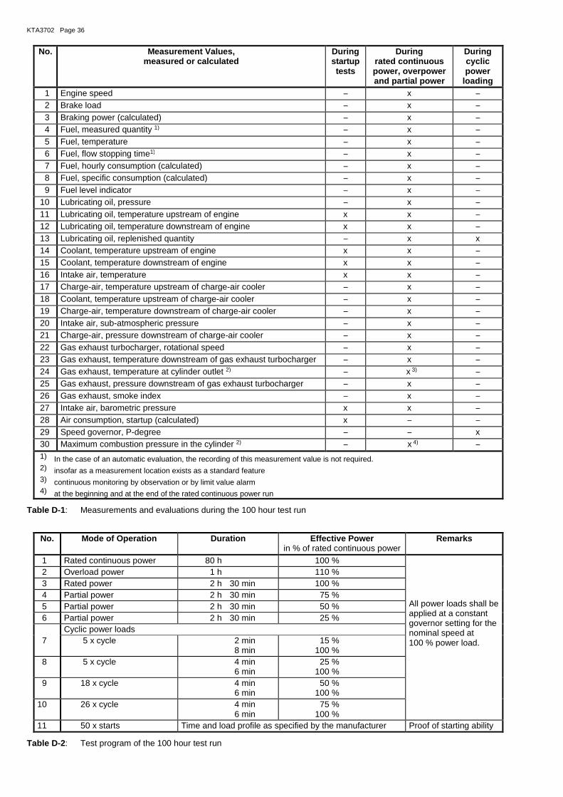
KTA3702 Page 36
No. Measurement Values, measured or calculated
During startup tests
During rated continuous power, overpower and partial power
During cyclic power
loading 1 Engine speed − x − 2 Brake load − x − 3 Braking power (calculated) − x − 4 Fuel, measured quantity 1) − x − 5 Fuel, temperature − x − 6 Fuel, flow stopping time1) − x − 7 Fuel, hourly consumption (calculated) − x − 8 Fuel, specific consumption (calculated) − x − 9 Fuel level indicator − x − 10 Lubricating oil, pressure − x − 11 Lubricating oil, temperature upstream of engine x x − 12 Lubricating oil, temperature downstream of engine x x − 13 Lubricating oil, replenished quantity − x x 14 Coolant, temperature upstream of engine x x − 15 Coolant, temperature downstream of engine x x − 16 Intake air, temperature x x − 17 Charge-air, temperature upstream of charge-air cooler − x − 18 Coolant, temperature upstream of charge-air cooler − x − 19 Charge-air, temperature downstream of charge-air cooler − x − 20 Intake air, sub-atmospheric pressure − x − 21 Charge-air, pressure downstream of charge-air cooler − x − 22 Gas exhaust turbocharger, rotational speed − x − 23 Gas exhaust, temperature downstream of gas exhaust turbocharger − x − 24 Gas exhaust, temperature at cylinder outlet 2) − x 3) − 25 Gas exhaust, pressure downstream of gas exhaust turbocharger − x − 26 Gas exhaust, smoke index − x − 27 Intake air, barometric pressure x x − 28 Air consumption, startup (calculated) x − − 29 Speed governor, P-degree − − x 30 Maximum combustion pressure in the cylinder 2) − x 4) − 1) In the case of an automatic evaluation, the recording of this measurement value is not required. 2) insofar as a measurement location exists as a standard feature 3) continuous monitoring by observation or by limit value alarm 4) at the beginning and at the end of the rated continuous power run
Table D-1: Measurements and evaluations during the 100 hour test run
No. Mode of Operation Duration Effective Power in % of rated continuous power
Remarks
1 Rated continuous power 80 h 100 % All power loads shall be applied at a constant governor setting for the nominal speed at 100 % power load.
2 Overload power 1 h 110 % 3 Rated power 2 h 30 min 100 % 4 Partial power 2 h 30 min 75 % 5 Partial power 2 h 30 min 50 % 6 Partial power 2 h 30 min 25 % Cyclic power loads 7 5 x cycle 2 min
8 min 15 % 100 %
8 5 x cycle 4 min 6 min
25 % 100 %
9 18 x cycle 4 min 6 min
50 % 100 %
10 26 x cycle 4 min 6 min
75 % 100 %
11 50 x starts Time and load profile as specified by the manufacturer Proof of starting ability
Table D-2: Test program of the 100 hour test run

KTA 3702 Page 37
Appendix E
Regulations Referred to in this Safety Standard
Regulations referred to in this safety standard are only valid in the version cited below. Regulations which are referred to within these regulations are valid only in the version that was valid when the latter regulations were established or issued.
Atomic Energy Act Act on the peaceful utilization of atomic energy and the protection against its haz-ards (Atomic Energy Act) of December 23, 1959 (BGBl. I, p. 814) as amended on July 15, 1985 (BGBl. I, p. 1565), most recently changed by law on August 28, 2013 (BGBl. I,2013, No. 52, p. 3313)
Radiation Protection Ordi-nance
Ordinance on the Protection against Damage and Injuries Caused by Ionizing Ra-diation (Radiation Protection Ordinance) of July 20, 2001 (BGBI. I, p. 1714; 2002 I p.1459), most recently changed by law on February 24 2012 (BGBI. I, p. 212)
PED Directive 2014/68/EU of the European Parliament and of the Council of 15 May 2014 on the harmonisation of the laws of the Member States relating to the mak-ing available on the market of pressure equipment
SiAnf (2012-11) Safety Requirements for Nuclear Power Plants of November 22, 2012 (BAnz of January 24, 2013)
Interpretations (2013-11) Interpretations of the Safety Requirements for Nuclear Power Plants of November 22, 2012, of November 29, 2013 (Banz of December 10, 2013)
KTA 1401 (2013-11) General Requirements Regarding Quality Assurance
KTA 1403 (2010-11) Ageing Management in Nuclear Power Plants
KTA 2101.3 (2000-12) Fire Protection in Nuclear Power Plants; Part 3: Fire Protection of Mechanical and Electrical Plant Components
KTA 2201.4 (2012-11) Design of Nuclear Power Plants against Seismic Events; Part 4: Components
KTA 3501 (1985-06) Reactor Protection System and Monitoring Equipment of the Safety System
KTA 3504 (2006-11) Electrical Drive Mechanisms of the Safety System in Nuclear Power Plants
Draft KTA 3701 (2012-11) General Requirements for the Electrical Power Supply in Nuclear Power Plants
KTA 3703 (2012-11) Emergency Power Facilities with Batteries and AC/DC Converters in Nuclear Power Plants
KTA 3704 (2013-11) Emergency Power Facilities with Static and Rotating Converters in Nuclear Power Plants
KTA 3705 (2006-11) Switchgear Facilities, Transformers and Distribution Networks for the Electrical Power Supply of the Safety System in Nuclear Power Plants
KTA 3904 (2007-11) Control Room, Remote Shutdown Station and Local Control Stations in Nuclear Power Plants
DIN ISO 8528-9 (1999-01) Reciprocating internal combustion engines driven alternating current generating sets - Part 9: Measurement and evaluation of mechanical vibrations (ISO 8528-9:1995)
DIN EN 60034-1 (VDE 0530-1)
(2011-02) Rotating electrical machines - Part 1: Rating and performance (IEC 60034-1:2010, modified); German version EN 60034-1:2010 + Cor.:2010
DIN EN 60034-2-1 (VDE 0530-2-1)
(2008-08) Rotating electrical machines - Part 4: Methods for determining synchronous ma-chine quantities from tests (IEC 60034-4:2008); German version EN 60034-4:2008
KTA3702 Page 38
DIN EN 60034-4 (VDE 0530-4)
(2009-04) Rotating electrical machines - Part 4: Methods for determining synchronous ma-chine quantities from tests (IEC 60034-4:2008); German version EN 60034-4:2008
DIN EN 10204 (2005-01) Metallic products - Types of inspection documents; German version EN 10204:2004
DIN EN 10216-1 (2009-11) Seamless steel tubes for pressure purposes - Technical delivery conditions - Part 1: Non-alloy steel tubes with specified room temperature properties; German ver-sion prEN 10216-1:2009
DIN EN 10216-2 (2009-11) Seamless steel tubes for pressure purposes - Technical delivery conditions - Part 2: Non-alloy and alloy steel tubes with specified elevated temperature properties; German version prEN 10216-2:2009
DIN EN 10216-3 (2009-11) Seamless steel tubes for pressure purposes - Technical delivery conditions - Part 3: Alloy fine grain steel tubes; German version prEN 10216-3:2009
DIN EN 10216-4 (2009-11) Seamless steel tubes for pressure purposes - Technical delivery conditions - Part 4: Non-alloy and alloy steel tubes with specified low temperature properties; Ger-man version prEN 10216-4:2009
DIN EN 10216-5 (2009-11) Seamless steel tubes for pressure purposes - Technical delivery conditions - Part 5: Stainless steel tubes; German version prEN 10216-5:2009
DIN EN 10217-1 (2009-10) Welded steel tubes for pressure purposes - Technical delivery conditions - Part 1: Non-alloy steel tubes with specified room temperature properties; German version prEN 10217-1:2009
DIN EN 10217-2 (2009-10) Welded steel tubes for pressure purposes - Technical delivery conditions - Part 2: Electric welded non-alloy and alloy steel tubes with specified elevated tempera-ture properties; German version prEN 10217-2:2009
DIN EN 10217-7 (2009-10) Welded steel tubes for pressure purposes - Technical delivery conditions - Part 7: Stainless steel tubes; German version prEN 10217-7:2009
DIN EN 10253-2 (2008-09) Butt-welding pipe fittings - Part 2: Non alloy and ferritic alloy steels with specific in-spection requirements; German version EN 10253-2:2007
DIN EN 10253-4 (2008-06) Butt-welding pipe fittings - Part 4: Wrought austenitic and austenitic-ferritic (du-plex) stainless steels with specific inspection requirements; German version EN 10253-4:2008
DIN EN 10253-4 Corrigendum 1
(2009-11) Butt-welding pipe fittings - Part 4: Wrought austenitic and austenitic-ferritic (du-plex) stainless steels with specific inspection requirements; German version EN 10253-4:2008, Corrigendum to DIN EN 10253-4:2008-06; German version EN 10253-4:2008/AC:2009
DIN EN 10028-1 (2009-07) Flat products made of steels for pressure purposes - Part 1: General require-ments; German version EN 10028-1:2007+A1:2009
DIN EN 10028-2 (2009-09) Flat products made of steels for pressure purposes - Part 2: Non-alloy and alloy steels with specified elevated temperature properties; German version EN 10028-2:2009
DIN EN 10028-7 (2008-02) Flat products made of steels for pressure purposes - Part 7: Stainless steels; Ger-man version EN 10028-7:2007
DIN EN 1563 (2010-03) Founding - Spheroidal graphite cast irons; German version EN 1563:2011
DIN EN 10213 (2008-01) Steel castings for pressure purposes; German version EN 10213:2007
DIN EN 10213/A1 (2011-08) Steel castings for pressure purposes; German version EN 10213:2007/prA1:2011
DIN EN 10222-1 (2002-07) Steel forgings for pressure purposes - Part 1: General requirements for open die forgings (includes Amendment A1:2002); German version EN 10222-1:1998 + A1:2002
DIN EN 10222-2 (2000-04) Steel forgings for pressure purposes - Part 2: Ferritic and martensitic steels with specified elevated temperature properties (including corrigendum AC:2000); Ger-man version EN 10222-2:1999 + AC:2000
DIN EN 10222-3 (1999-02) Steel forgings for pressure purposes - Part 3: Nickel steels with specified low tem-perature properties; German version EN 10222-3:1998
DIN EN 10222-4 (2001-12) Steel forgings for pressure purposes - Part 4: Weldable fine grain steels with high proof strength (includes Amendment A1:2001); German version EN 10222-4:1998 + A1:2001
DIN EN 10222-5 (2000-02) Steel forgings for pressure purposes - Part 5: Martensitic, austenitic and austen-itic-ferritic stainless steels; German version EN 10222-5:1999

KTA 3702 Page 39
DIN EN 10272 (2008-01) Stainless steel bars for pressure purposes; German version EN 10272:2007
DIN EN 3506 (2003-03) Aerospace series - Hot rolled sheets and plates in heat resisting alloys - Thick-ness 2,0 mm <= a <= 100 mm; Dimensions; German and English version EN 3506:2001
DIN EN 10025 (2011-04) Hot rolled products of structural steels – all Parts; German version prEN 10025:2011
DIN EN 10250-1 (1999-12) Open die steel forgings for general engineering purposes - Part 1: General re-quirements; German version EN 10250-1:1999
DIN EN 10250-2 (1999-12) Open die steel forgings for general engineering purposes - Part 2: Non-alloy qual-ity and special steels; German version EN 10250-2:1999
DIN EN 10250-4 (2000-02) Open die steel forgings for general engineering purposes - Part 4: Stainless steels; German version EN 10250-4:1999
DIN EN 10250-4 Corrigendum 1
(2008-12) Open die steel forgings for general engineering purposes - Part 4: Stainless steels; German version EN 10250-4:1999, Corrigendum to DIN EN 10250-4:2000-02
DIN EN 10207 (2005-06) Steels for simple pressure vessels - Technical delivery requirements for plates, strips and bars; German version EN 10207:2005
DIN EN 10273 (2008-02) Hot rolled weldable steel bars for pressure purposes with specified elevated tem-perature properties; German version EN 10273:2007
DIN EN 10272 (2008-01) Stainless steel bars for pressure purposes; German version EN 10272:2007
DIN EN 10224 (2005-12) Non-alloy steel tubes and fittings for the conveyance of water and other aqueous liquids - Technical delivery conditions; German version EN 10224:2002 + A1:2005
DIN EN 10297-1 (2003-06) Seamless circular steel tubes for mechanical and general engineering purposes - Technical delivery conditions - Part 1: Non-alloy and alloy steel tubes; German version EN 10297-1:2003
DIN EN 10297-2 (2006-02) Seamless steel tubes for mechanical and general engineering purposes - Tech-nical delivery conditions - Part 2: Stainless steel; German version EN 10297-2:2005
DIN EN 10297-2 Corrigendum 1
(2007-06) Seamless steel tubes for mechanical and general engineering purposes - Tech-nical delivery conditions - Part 2: Stainless steel; German version EN 10297-2:2005, Corrigenda to DIN EN 10297-2:2006-02; German version EN 10297-2:2005/AC:2007
DIN EN 10296-1 (2004-02) Welded circular steel tubes for mechanical and general engineering purposes - Technical delivery conditions - Part 1: Non-alloy and alloy steel tubes; German version EN 10296-1:2002
DIN EN 10296-2 (2006-02) Welded circular steel tubes for mechanical and general engineering purposes - Technical delivery conditions - Part 2: Stainless steel; German version EN 10296-2:2005
DIN EN 10296-2
Corrigendum 1
(2007-06) Welded circular steel tubes for mechanical and general engineering purposes - Technical delivery conditions - Part 2: Stainless steel; German version EN 10296-2:2005, Corrigenda to DIN EN 10296-2:2006-02; German version EN 10296-2:2005/AC:2007
DIN EN 10312 (2005-12) Welded stainless steel tubes for the conveyance of water and other aqueous liq-uids - Technical delivery conditions; German version EN 10312:2002 + A1:2005
DIN EN 10088-2 (2012-01) Stainless steels - Part 2: Technical delivery conditions for sheet/plate and strip of corrosion resisting steels for general purposes; German version prEN 10088-2:2011
DIN EN 10088-3 (2012-01) Stainless steels - Part 3: Technical delivery conditions for semi-finished products, bars, rods, wire, sections and bright products of corrosion resisting steels for gen-eral purposes; German version prEN 10088-3:2011
DIN EN 10283 (2010-06) Corrosion resistant steel castings; German version EN 10283:2010
DIN EN 10083-1 (2006-10) Steels for quenching and tempering - Part 1: General technical delivery condi-tions; German version EN 10083-1:2006
DIN EN 10083-2 (2006-10) Steels for quenching and tempering - Part 2: Technical delivery conditions for non alloy steels; German version EN 10083-2:2006
DIN EN 10083-3 (2007-01) Steels for quenching and tempering - Part 3: Technical delivery conditions for al-loy steels; German version EN 10083-3:2006
KTA3702 Page 40
DIN EN 10083-3 Corrigendum 1
(2009-01) Steels for quenching and tempering - Part 3: Technical delivery conditions for al-loy steels; German version EN 10083-3:2006, Corrigendum to DIN EN 10083-3:2007-01; German version EN 10083-3:2006/AC:2008
DIN EN 10088-3 (2012-01) Stainless steels - Part 3: Technical delivery conditions for semi-finished products, bars, rods, wire, sections and bright products of corrosion resisting steels for gen-eral purposes; German version prEN 10088-3:2011
DIN EN ISO 3506-1 (2010-04) Mechanical properties of corrosion-resistant stainless steel fasteners - Part 1: Bolts, screws and studs (ISO 3506-1:2009); German version EN ISO 3506-1:2009
DIN EN ISO 3506-2 (2010-04) Mechanical properties of corrosion-resistant stainless steel fasteners - Part 2: Nuts (ISO 3506-2:2009); German version EN ISO 3506-2:2009
DIN EN ISO 3506-3 (2010-04) Mechanical properties of corrosion-resistant stainless steel fasteners - Part 3: Set screws and similar fasteners not under tensile stress (ISO 3506-3:2009); German version EN ISO 3506-3:2009
DIN EN 10269 (2011-12) Steels and nickel alloys for fasteners with specified elevated and/or low tempera-ture properties; German version prEN 10269:2011
DIN EN 10216-2 (2007-10) Seamless steel tubes for pressure purposes - Technical delivery conditions - Part 2: Non alloy and alloy steel tubes with specified elevated temperature properties; German version EN 10216-2:2002+A2:2007
DIN EN 10216-5 (2009-11) Seamless steel tubes for pressure purposes - Technical delivery conditions - Part 5: Stainless steel tubes; German version prEN 10216-5:2009
DIN EN 10217-2 2005-04 Welded steel tubes for pressure purposes - Technical delivery conditions - Part 2: Electric welded non-alloy and alloy steel tubes with specified elevated tempera-ture properties; German version EN 10217-2:2002 + A1:2005
DIN EN 10217-7 (2005-09) Welded steel tubes for pressure purposes - Technical delivery conditions - Part 7: Stainless steel tubes; German version EN 10217-7:2005
DIN EN 10283 (2010-06) Corrosion resistant steel castings; German version EN 10283:2010
AD 2000 Code of the Series HP (Manufacturing and Testing) and W (Materials):
AD 2000 - HP 0 (2011-05) General principles of design, manufacture and associated tests
AD 2000 - HP 1 (2009-10) Design and construction
AD 2000 - HP 2/1 (2011-05) Procedure testing for joining processes - Procedure testing for welded joints
AD 2000 - HP 3 (2007-02) Welding supervisors, welder
AD 2000 - HP 4 (2002-04) Test supervisors and testers in non-destructive testing
AD 2000 - HP 5/1 (2008-02) Manufacture and testing of joints - Principles of welding practice
AD 2000 - HP 5/2 (2011-05) Manufacture and testing of joints - Production testing of welds, testing of the par-ent metal after post-weld heat treatment
AD 2000 - HP 5/3 (2011-05) Manufacture and testing of joints - Non-destructive testing of welded joints
AD 2000 - HP 5/3 Annex 1 (2002-01) Non-destructive testing of welded joints - Minimum requirements for non-destruc-tive testing methods
AD 2000 - HP 7/1 (2000-10) Heat treatment - General principles
AD 2000 - HP 7/2 (2009-03) Heat treatment - Ferritic steels
AD 2000 - HP 7/3 (2001-09) Heat treatment - Austenitic steels
AD 2000 - HP 8/2 (2000-10) Testing of steel sections
AD 2000 - HP 30 (2003-01) Performance of pressure tests
AD 2000 - W 1 (2006-07) Flat products of unalloyed and alloy steels
AD 2000 - W 2 (2008-02) Austenitic and austenitic-ferritic steels
AD 2000 - W 3/2 (2000-10) Cast iron materials - Spheroidal-graphite cast iron non-alloy and low alloy
AD 2000 - W 4 (2008-05) Tubes made from non-alloyed and alloy steels
AD 2000 - W 5 (2009-03) Cast steel
AD 2000 - W 7 (2008-05) Bolts and nuts made from ferritic steels
AD 2000 - W 9 (2010-11) Steel flanges
AD 2000 - W 13 (2008-11) Forgings and rolled components made of non-alloy and alloy steels

KTA 3702 Page 41