Embed Size (px)
Citation preview

KTC 2
WN 057xxx 45532
1 06/10
Änderungen vorbehalten
Subject to change without
DORMA GmbH + Co.KG DORMA Platz 1 D-58256 Ennepetal • Tel. +49 (0) 23 33 / 793-0 • www.dorma.com Automatic Division Postfach 40 09 D-58247 Ennepetal • Fax
+49 (0) 23 33 / 79 34 95
1
KTC 2
Revolving door
Initial operation manual

KTC 2
WN 057xxx 45532
2 06/10
Änderungen vorbehalten
Subject to change without
DORMA GmbH + Co.KG DORMA Platz 1 D-58256 Ennepetal • Tel. +49 (0) 23 33 / 793-0 • www.dorma.com Automatic Division Postfach 40 09 D-58247 Ennepetal • Fax
+49 (0) 23 33 / 79 34 95
2
Contents Page 1. For your safety 3 - 4
2. System overview 5
3. Overview of drive and control components 6 3.1 Main control unit (-X101) 6 3.2 Installation position of main
control unit 7 3.3 Drive unit 8 3.4 Locking device (optional) 8 3.5 Drive unit of sliding door 9 3.6 Locking device of sliding door 9 3.7 Collector 10 3.8 Control unit (-X401) 11 3.9 Malfunction indicator at door post 11 3.10 Switches/pushbutton at door post
(with autom. sliding door operator) 12
3.10 Switches/pushbutton at door post (without autom. sliding door operator) 13
3.12 Canopy 13 3.13 Cable guiding at door system 14
4. Electrical connection of revolving components 15 4.1 Power supply of revolving
components 15 4.2 Power supply via USV (emergency
power supply unit) 16 4.3 Connecting the motor 17 - 18 4.4 Connecting the incremental encoder 19 4.5 Connecting the X-position sensor 20 4.6 Data cable coming from collector 21 - 22 4.7 Connection of light
barriers/safety contact strips 23 - 25 4.8 With manually-operated sliding door 26 4.8 Limit switch of showcase 26
5. Connection diagram for optional sliding door 27 5.1 Connection diagram for ES 200 27 5.2 Connection diagram for ES 200
locking device 28 5.3 Connection diagram for safety
sensors of sliding door 29 5.4 Wiring of power supply for ES 200 30 5.5 Connection of 4Safe sensors 31 5.6 Connection of AIR16 sensors 32 5.7 Connection of electromechanical
locking device 33 5.8 Connection of presence sensor for Night-/Bank Function 34
6. Electrical connection of static components 35 6.1 Control unit (-X401) 35 6.2 PE (protective earth) connection 35 6.3 Connection of equipotential bonding 35 6.4 Connection of collector 36 6.5 Connection of safety contact strips at post 37 - 38
6.6 Connection of canopy-integrated sensors 39 - 40
6.7 Connection of pushbutton for Emergency Stop function and program switch 41 - 42
6.8 Connection of program switch and Night-/Bank activator 43
6.9 Connection of electronic program switch and Night-/Bank activator 44
6.10 Connection of disabled access pushbutton 45
6.11 Connection of pushbutton for Emergency Stop function 46
6.12 Connection of presence sensors 47 - 48 6.13 Connection of radar motion
detectors 49 - 50 6.14 Connection of fault indicator 51

KTC 2
WN 057xxx 45532
3 06/10
Änderungen vorbehalten
Subject to change without
DORMA GmbH + Co.KG DORMA Platz 1 D-58256 Ennepetal • Tel. +49 (0) 23 33 / 793-0 • www.dorma.com Automatic Division Postfach 40 09 D-58247 Ennepetal • Fax
+49 (0) 23 33 / 79 34 95
3
Contents Page 7. Commissioning 52
7.1 Basic requirements 52 7.2 Adjustment of infrared sensors 52 - 54 7.3 DCW program switch 55 7.4 Adjustment of control unit and frequency converter 56 7.5 DIP switch “input module/output
module”: 57
8. Adjustment at operator 58 8.1 Standard menu 59 8.2 Adjustment of multi-digit
parameters 60 8.3 Parameters 61 8.4 Parameter adjustment of frequency
converter 62 8.5 Status indicators 63 8.6 Changing the code values 63 8.7 Changing the parameter set 63 8.8 Transferring parameter sets 64 8.9 Standard frequency converter
adjustment for 5.4 m system 64
9. Commissioning of revolving door
system 65 - 66
10. Commissioning of sliding door
system 67 - 70
11. Functional testing 71
12. Functional characteristics 72 12.1 Revolving door 72
12.2 Sliding door 73 - 74
13. Further functions of revolving door 75 13.1 SlowStop 75 13.2 Obstruction stop 76 13.3 Error stop 76 13.4 Emergency Stop 76 13.5 Safety stop 76 13.6 Locking/unlocking 76 13.7 Control/activation of automatic
sliding door 77 13.8 Output functions 78
14. Safety equipment 78 - 79
15. Error display/warning messages 80 15.1 Error indication via seven- segment display at CPU 80 - 81 15.2 Warning messages 81 15.3 External seven-segment display 82 15.4 Display at program switch for
revolving door 83 15.4 Malfunction table for sliding door 84
16. Further information 85 16.1 Position overview 85 16.2 Warning 85 16.3 Parametrisation menus of handheld (PDA) 85-86 16.4 Connection of handheld 100 16.5 Access to parametriermenu 101

058016-45532_29052012KTC_2_Comissioning_instructions_(GB).doc
KTC 2 (MS9)
4
1. For your safety This documentation contains important information regarding the mounting and the safe operation of the door system. Please read these instructions carefully before using the system.
It is important for your personal safety to abide by all enclosed instructions.
Using control elements, making adjustments or performing procedures that are not described in this documentation might cause electric shocks, danger caused by electric voltage/current and/or danger due to mechanical incidents. Please keep these documents for further reference and hand them over to the person in charge in case the system is transferred to another party.
Explanation of symbol Please note This symbol indicates
dangers that might cause personal or material damage or even kill people.
At the revolving door The KTC 2 is a two-wing revolving door. The door is equipped with an integrated night shield and either breakout wings or an automatic sliding door. The wings may be equipped with showcases. The KTC 2 is an entry/exit and connects two separate areas of a building. As a rule, it links the inside of a building with the outside. Thanks to its technical design and good geometry, there is almost no direct connection between the two separate areas. Therefore these door systems limit draughts and noise and control the traffic between the two areas. The revolving door may be locked in order to close the entrance/exit. The system has been adjusted in our factory; however, you may perform minor adjustments regarding the speed and for example Slow-Stop times.
Limitation of liability The KTC 2 may only be used according to its specified intended application. DORMA GmbH + Co. KG will not accept any liability for damage resulting from unauthorised modifications of the KTC 2. Furthermore components/accessories that have not been approved by DORMA are exempted from liability.
Danger spots at closing edges Automatic doors might cause hazards by crushing, shearing, hitting and drawing-in at the different closing edges.
Mainclosing edge
Opposingclosing edge
Secondaryclosing edge

058016-45532_29052012KTC_2_Comissioning_instructions_(GB).doc
KTC 2 (MS9)
5
At the sliding door
Main closingedge
Secondaryclosing edge
Depending on the structural conditions, the prevailing door version and the available safety equipment, we cannot completely exclude residual risks such as crushing and hitting (with limited force).
Safety during installation and commissioning An incorrectly performed installation
may cause serious injury. Only qualified staff is allowed access
to the control unit. The working area has to be secured
against unauthorised access from other people. Falling items or tools might cause injuries.
The revolving door has to be protected against water and other liquids.
The mounting of the revolving door described herein is only an example. Structural or local conditions, available tools or other conditions might suggest a different approach.
In any case, the way of mounting and the mounting equipment, like for example screws and wall plugs, have to be adequate with regard to the structural conditions (steel structure, wood, concrete etc.).
Following the successful installation of the system, check the settings and the proper functioning of the revolving door and the respective safety equipment.
Please ensure that the system is correctly installed with regard to mechanical and electrical aspects before you start with the commissioning.
The protective earth conductor has to be connected.
The safety sensors must be connected. Separately supplied components such as
the program switch, the pushbutton for the Emergency Stop function, sensors and activators (radar motion detectors, canopy-integrated sensors) have to be mounted and connected.
Safety instructions
Work on electrical equipment may only be performed by properly qualified staff (electricians).
Dangerous electrical voltage! Voltage may cause electric shocks and burns.
Do not use HQ lamps/fluorescent lamps as they interact with the safety sensors.
Before performing any kind of work, de-energise the system (disconnect it from power supply) and secure it against accidental reactivation.
Maintenance and other work at the door system may only be performed by properly qualified staff or authorised people.
The door system is no playground: Please ensure that the system is only used to its specified intended application and keep playing children away from the door system. Do not allow children to play with the KTC 2 or its adjustment and control devices.
Children may only use the door system under supervision of an adult.
Never stick metal objects into the openings of the KTC 2; otherwise you might sustain an electric shock.
Glass door wings have to be made of safety glass.
Do not accelerate the turnstile by hand.
Do not enter the door system with bulky items. (Set system to summer configuration and open the sliding door)
Enter the system quickly and only while the opening width is sufficiently big.
Also leave the door system quickly while the exit is big enough to go through.
Do not change your walking direction within the revolving door system.
When using the door system, follow the rotation of the system at permanent speed and do not stop unless required.
Keep parts of your body and objects out of the rotation range of the turnstile
Make sure that the environment of the door system is sufficiently illuminated.
The distance between the bottom edge of the wing and the floor finish amounts to 40 mm. You should always prefer a level and firm underground without gaps to floor finishes such as floor mats. Do not use soft undergrounds like carpets. When using floor mats, they have to be fixed to each other and to the ground. The distance between the different profiles of the mats must not exceed 4 mm.
The rotational speed has to be adjusted so that it is suitable for the expected user group (also disabled or elderly people). Maybe you will even have to reduce the pre-adjusted speed (original settings).

058016-45532_29052012KTC_2_Comissioning_instructions_(GB).doc
KTC 2 (MS9)
6
During the operation of the system, you are only allowed to remain within the door system or in direct proximity of the entry/exit for as long as you require for entering or leaving the two areas. (Only specially trained staff during maintenance work is may be excluded from this rule.)
Do not step onto the glass ceiling while the system is in use.
Do not use electric discharge lamps within the close range of the revolving door system as they may impair the proper functioning of the infrared sensors.
In case the glass of the ceiling or the wings brakes, the system has to be put out of operation immediately and secured against entry. Immediately contact DORMA Service to order the required spare parts.
Safety check and system approval Before the first commissioning and depending on requirements, however, at least once a year, the KTC 2 has to be inspected by a properly qualified technician and serviced as required. This inspection may be performed during the maintenance of the system. A properly trained person (by DORMA) has to perform the inspection and approve the system with the aid of the inspection book. The respective results have to be documented in accordance with DIN 18650-2 and the facility operator has to keep these documents for at least one year.
We would recommend taking out a maintenance agreement with DORMA.
Maintenance All kinds of maintenance work may only be performed by specially trained DORMA staff. Disconnect the system from all mains (switch off fuse) while working on the system.
Wear This door system contains wear parts that have to be inspected and replaced (as required) in regular intervals. A wear part list is available on request. Only use original spare parts.
Care The system has to be de-energised (disconnected from power supply) before cleaning. Switch off fuse to ensure that the system is properly de-energised. You may clean the KTC 2 with a damp cloth and standard commercial detergents. Do not use scouring agents for cleaning purposes as they might damage the surface finish. Ensure that no water or other liquids drop onto or into the system. Never stick metal objects into the openings of the KTC 2; otherwise you might sustain an electric shock.
Recycling and disposal Both the KTC 2 and its packing mainly consist of recyclable raw material. The KTC 2 and the respective accessories/components must not
be disposed of as domestic waste. Please ensure that the old appliance and the respective components/accessories (if available) are properly disposed of and abide by the prevailing national statutory provisions when disposing of the system and its components.

058016-45532_29052012KTC_2_Comissioning_instructions_(GB).doc
KTC 2 (MS9)
7
2. System overview Collector outside inside Drive unit Main control unit –X101 Control elements Electrom. bolt locking device
(optional)
Manual lock release with electromech. bold locking device and -X401 control unit
058016-45532_29052012KTC_2_Comissioning_instructions_(GB).doc
KTC 2 (MS9)
8
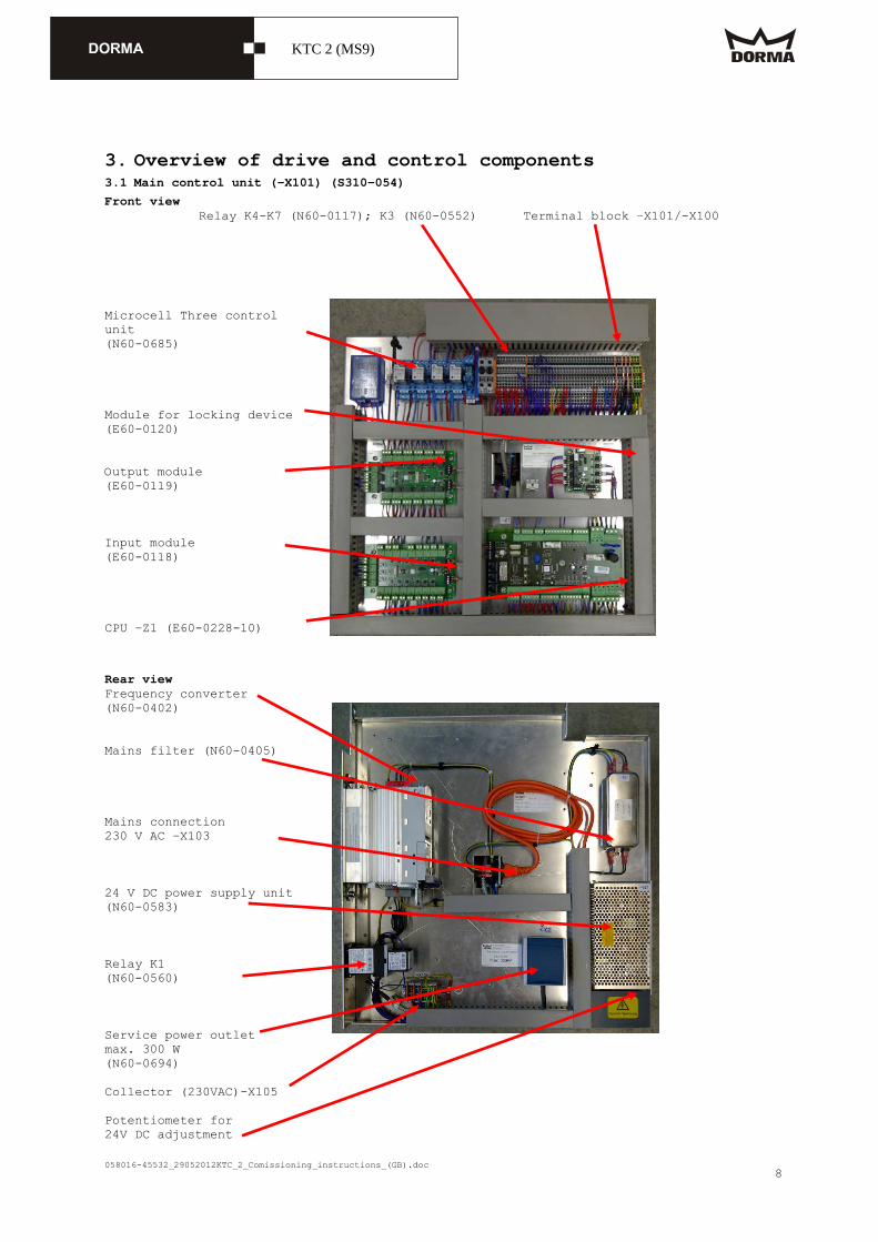
3. Overview of drive and control components 3.1 Main control unit (-X101) (S310-054)
Front view Relay K4-K7 (N60-0117); K3 (N60-0552) Terminal block –X101/-X100 Microcell Three control unit (N60-0685) Module for locking device (E60-0120) Output module (E60-0119) Input module (E60-0118) CPU –Z1 (E60-0228-10)
Rear view Frequency converter (N60-0402) Mains filter (N60-0405) Mains connection 230 V AC –X103 24 V DC power supply unit (N60-0583) Relay K1 (N60-0560) Service power outlet max. 300 W (N60-0694) Collector (230VAC)-X105 Potentiometer for 24V DC adjustment

058016-45532_29052012KTC_2_Comissioning_instructions_(GB).doc
KTC 2 (MS9)
9
3.2 Installation position of main control unit (-X101) Secure control unit in top position with the aid of the chain.
The control unit is provided with a cover (N25-0275)
in order to protect it from dust and similar.

058016-45532_29052012KTC_2_Comissioning_instructions_(GB).doc
KTC 2 (MS9)
10
3.3 Drive unit X-position sensor – S17(N60-0072) Shield clips AC motor -M1 (N70-0116) Compl. incremental encoder (S310-053)
3.4 Locking device (optional) Electromechanical bolt locking device (N60-0464 + E50-947) In the event of a failure of the locking device, you may lock or unlock the door through the drill hole for maintenance purposes. The hole is located at the side of the -X401 control unit (see "system overview"). (E50-0327) Here you will find the sticker "emergency unlocking".
Limit switch for electromechanical bolt locking device unlocked locked

058016-45532_29052012KTC_2_Comissioning_instructions_(GB).doc
KTC 2 (MS9)
11
3.5 Drive unit for sliding door (optional) ES 200 power supply unit (N60-0591) ES 200 motor ES 200 basic/expansion module (N60-0586 / N60-0589) Door wing
3.6 Locking device of sliding door (optional) Locking feedback contact (N60-686) Rod to unlock electric sliding panel

058016-45532_29052012KTC_2_Comissioning_instructions_(GB).doc
KTC 2 (MS9)
12
3.7 Collector Collector (N60-0669) Cable ties for fixing of collector

058016-45532_29052012KTC_2_Comissioning_instructions_(GB).doc
KTC 2 (MS9)
13
3.8 Canopy-integrated (S310-055) control unit (-X401) 230 V AC power supply & collector connection Output module (E60-0119) Input module (E60-0118)
3.9 Malfunction indicator at door post

058016-45532_29052012KTC_2_Comissioning_instructions_(GB).doc
KTC 2 (MS9)
14
3.10 Switches/pushbutton at door post (with autom. sliding door operator) Malfunction indicator (N60-0680/N60-0681) Electronic pushbutton for Emergency Stop function (N60-0459) KT program switch (N60-0683) ST program switch (N60-0684) Key switch (Optional) (N60-0691) Disabled access pushbutton (N60-0076)

058016-45532_29052012KTC_2_Comissioning_instructions_(GB).doc
KTC 2 (MS9)
15
3.11 Switches/pushbutton at door post (systems without autom. sliding door operator) KT program switch Emergency Stop pushbutton Disabled access pushbutton (N60-0109) (N60-0502-10) (N60-0076)
3.12 Canopy Radar motion detectors (here N60-0690) or Easy Motion Stereo (N60-0709) Canopy-integrated sensor (active infrared sensor) (N60-0514-10) + 1 m prism (N60-0548-30)

058016-45532_29052012KTC_2_Comissioning_instructions_(GB).doc
KTC 2 (MS9)
16
3.13 Cable guiding at door system Here the girder for the sliding door is used within the door system.
Exterior view The cables run behind the canopy at the outer part of the door system. The cables for the outer part of the door system run clockwise, starting at the control unit (-X401).

058016-45532_29052012KTC_2_Comissioning_instructions_(GB).doc
KTC 2 (MS9)
17
4. Electrical connection of revolving components 4.1 Power supply of revolving components The red line indicates how the 230 V AC mains cable is laid from the collector to the control unit. The outlet for the low-heat devices (located at the control unit) must be connected to this collector cable. The plug for the low-heat devices is also used as mains switch; simply unplug it to disconnect the power supply unit from all mains.

058016-45532_29052012KTC_2_Comissioning_instructions_(GB).doc
KTC 2 (MS9)
18
4.2 Power supply via USV emergency power supply unit (optional) For systems with USV emergency power supply unit, the plug for the low-heat devices (mains switch –X103) must be connected to the USV while the other 230 V AC adaptor cable is used to link the USV and the control unit –X103.

058016-45532_29052012KTC_2_Comissioning_instructions_(GB).doc
KTC 2 (MS9)
19
4.3 Connecting the motor: The motor is realised as delta connection, i. e. set jumpers as indicated in the picture. Thermal sensor (cable No.:19) Motor (cable No.:16) Electr. brake (cable No.:18)
Please note: The motor cable (No. 16) is dismantled at the side where it is connected to the control unit (-X101) and at the system girder so that the shielding is visible. The part of the cable that has been dismantled has to be connected to the control unit and the motor (fixed with the respective clips).

058016-45532_29052012KTC_2_Comissioning_instructions_(GB).doc
KTC 2 (MS9)
20
Shielded clip for motor cable (No. 16) EMC screw connection of motor cable (No. 16)

058016-45532_29052012KTC_2_Comissioning_instructions_(GB).doc
KTC 2 (MS9)
21
4.4 Connecting the incremental encoder Set adjustment screw to "2". Terminal connectors CPU -Z1
The incremental encoder is located at the drive unit. The terminal connectors of the white plug of incremental encoder cable No. 5 must point towards the rotor. Reverse polarity will destroy the incremental encoder. In order to minimise possible interferences, the cable has to be laid separately - i. e. away from other cables such as the motor cable. Incremental encoder cable No. 5 has been dismantled in front of the incremental encoder so that the shielding of the cable is visible. The dismantled part of the cable must be fixed under the shield clips. The incremental encoder cable is connected to the CPU (-Z1).

058016-45532_29052012KTC_2_Comissioning_instructions_(GB).doc
KTC 2 (MS9)
22
4.5 Connecting the X-position sensor:
Installation position of X-position sensor: A distance of 3 - 4 mm is required between the proximity sensor and the cam. Move cam for fine adjustment of starting position.
3 - 4 mm

058016-45532_29052012KTC_2_Comissioning_instructions_(GB).doc
KTC 2 (MS9)
23
4.6 Data cable for collector Here you see how the cables run from the static to the revolving part of the door system. The cable comes from the static part of the revolving door and runs to the collector. The above sketch shows the two cables running to the collector through the central drill hole.

058016-45532_29052012KTC_2_Comissioning_instructions_(GB).doc
KTC 2 (MS9)
24
The green line indicates how the collector cable runs from the collector to the control unit (-X401). Collector Control unit –X401 Cams for X-position Collector cable The cams are used to adjust the "closed" position of the door.
058016-45532_29052012KTC_2_Comissioning_instructions_(GB).doc
KTC 2 (MS9)
25
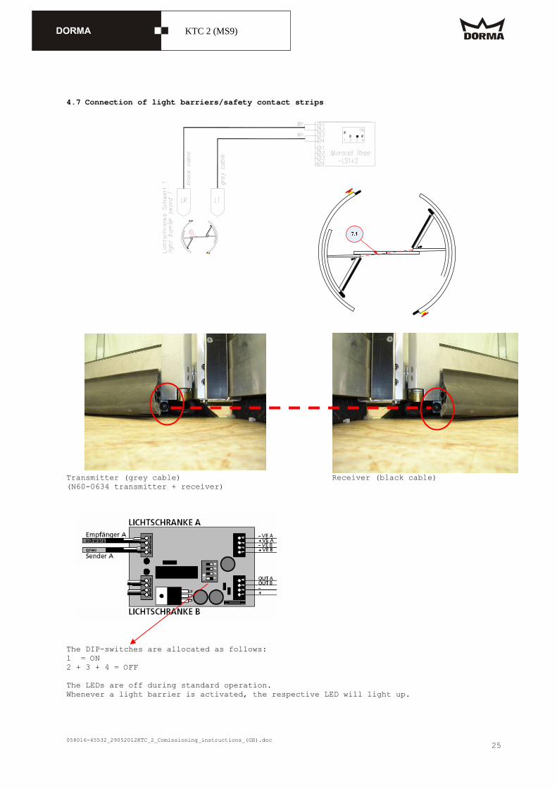
4.7 Connection of light barriers/safety contact strips
Transmitter (grey cable) Receiver (black cable) (N60-0634 transmitter + receiver) The DIP-switches are allocated as follows: 1 = ON 2 + 3 + 4 = OFF The LEDs are off during standard operation. Whenever a light barrier is activated, the respective LED will light up.

058016-45532_29052012KTC_2_Comissioning_instructions_(GB).doc
KTC 2 (MS9)
26
The red line indicates how the cable is laid from the control unit to the showcase door. (Light barrier and safety contact strips, cables No. 30 + 32) Set jumpers at the -X101 control unit for all safety contact strips that are not required (e. g. systems without showcases).

058016-45532_29052012KTC_2_Comissioning_instructions_(GB).doc
KTC 2 (MS9)
27

058016-45532_29052012KTC_2_Comissioning_instructions_(GB).doc
KTC 2 (MS9)
28
4.8 With breakout wing In addition, the following jumper is required (-X101: +24 V/31).
4.9 Limit switch for showcase
For systems without showcase, set jumper between 55 and 58!

058016-45532_29052012KTC_2_Comissioning_instructions_(GB).doc
KTC 2 (MS9)
29
5. Connection diagram for optional sliding door 5.1 Connection diagram for ES 200 ES 200 basic module (N60-0586) ES 200 I/O module (N60-0589)
In addition, the following jumper is required (-X101: +24 V/60).

058016-45532_29052012KTC_2_Comissioning_instructions_(GB).doc
KTC 2 (MS9)
30
5.2 Connection of ES 200 locking device (Option) Limit switch (Please note that the limit switches are not activated while the door is locked)

058016-45532_29052012KTC_2_Comissioning_instructions_(GB).doc
KTC 2 (MS9)
31
5.3 Connection diagram for safety sensors of sliding door
5.4 Adjustment of Active 8.x or IRIS ON 2 m * 2.5 m antenna 2 m-prism You may use the "IRIS ON" safety sensor instead of the "Active 8.1 ON" sensor. However, in this case an activation of the sliding door is not possible as only the canopy-integrated radar motion detectors are activated (and their activation also depends on the setting of the respective program switch). Designation Remote
control Value
Output configuration 1 Maximum duration of presence detection
1
Sensitivity (presence detection)
1 - 2 (1 = DIN 18650)
Monitoring mode 1 Number of infrared light curtains
1
Installation configuration (height/frequency)
1
Redirectioning of output for safety sensor
0
Sensitivity of radar detector 2-3

058016-45532_29052012KTC_2_Comissioning_instructions_(GB).doc
KTC 2 (MS9)
32
5.5 Wiring of power supply for ES 200
Connection of ES 200 power supply unit

058016-45532_29052012KTC_2_Comissioning_instructions_(GB).doc
KTC 2 (MS9)
33
5.6 Connection of 4Safe sensors
You may also bridge individual sensors at the -X101 terminal block for testing purposes.
Do not forget to disconnect the sensor cable at the terminal block.
Jumper for example between:
23 - 24 Wing sensors 1
25 - 26 Wing sensors 2
27 - 28 Pre-detection sensor 1
29 - 30 Pre-detection sensor 2

058016-45532_29052012KTC_2_Comissioning_instructions_(GB).doc
KTC 2 (MS9)
34
5.7 Connection of AIR16 sensors (not DIN 18650) Connection terminals for AIR16
Via flat cable is it possible to connect more sensors together.

058016-45532_29052012KTC_2_Comissioning_instructions_(GB).doc
KTC 2 (MS9)
35
5.8 Connection of electromechanical Locking device (optional)
The fixings of the limit switches must be screwed down tight.
CPU setting #el. locking devices
Electromechanical bolt locking device no = 0, yes = 1
1

058016-45532_29052012KTC_2_Comissioning_instructions_(GB).doc
KTC 2 (MS9)
36
5.9 Connection of presence sensor for winter configuration (OPTION) Connection/adjustment of SpotScan sensors Please consider the SpotScan instructions for further information.
Adjustment of DIP-switches DIP 1 = OFF frequency 1 DIP 2 = ON Background-suppression DIP 3 = OFF Passive output (NC contact) The detection range has to be adjusted so that people are easily detected whenever trapped inside one of the sections.

058016-45532_29052012KTC_2_Comissioning_instructions_(GB).doc
KTC 2 (MS9)
37
6. Electrical connection of static components The static components are connected to the revolving components behind the right internal canopy cover.
6.1 Control unit (-X401) -X400 -X401
6.2 PE (protective earth) connection
6.3 Connection of equipotential bonding Always earth (ground) door system with the aid of an external equipotential bonding. Install the bonding at a suitable position within the door system - depending on prevailing conditions. Please note that at least 6 mm² are required for the external connection.
The power supply (incl. PE) must be properly wired.
De-energise (disconnect from mains) power supply line and protect against reactivation.

058016-45532_29052012KTC_2_Comissioning_instructions_(GB).doc
KTC 2 (MS9)
38
6.4 Connection of collector

058016-45532_29052012KTC_2_Comissioning_instructions_(GB).doc
KTC 2 (MS9)
39
6.5 Connection of safety contact strips at post

058016-45532_29052012KTC_2_Comissioning_instructions_(GB).doc
KTC 2 (MS9)
40

058016-45532_29052012KTC_2_Comissioning_instructions_(GB).doc
KTC 2 (MS9)
41
6.6 Connection of canopy-integrated sensors

058016-45532_29052012KTC_2_Comissioning_instructions_(GB).doc
KTC 2 (MS9)
42

058016-45532_29052012KTC_2_Comissioning_instructions_(GB).doc
KTC 2 (MS9)
43
6.7 Connection of pushbutton for Emergency Stop function/program switch (required for systems with sliding panels)
Key switch Program switch KT program switch for sliding door (ST) For systems with breakout wings you may use any program switch but the ST program switch for sliding doors (see image above).

058016-45532_29052012KTC_2_Comissioning_instructions_(GB).doc
KTC 2 (MS9)
44
Connect to terminal block X6.

058016-45532_29052012KTC_2_Comissioning_instructions_(GB).doc
KTC 2 (MS9)
45
6.8 Connection of program switch and Night-/Bank activator (option) Systems with manual sliding door require a mechanical program switch. However, you may also install the DCW KT program switch as an option.
058016-45532_29052012KTC_2_Comissioning_instructions_(GB).doc
KTC 2 (MS9)
46
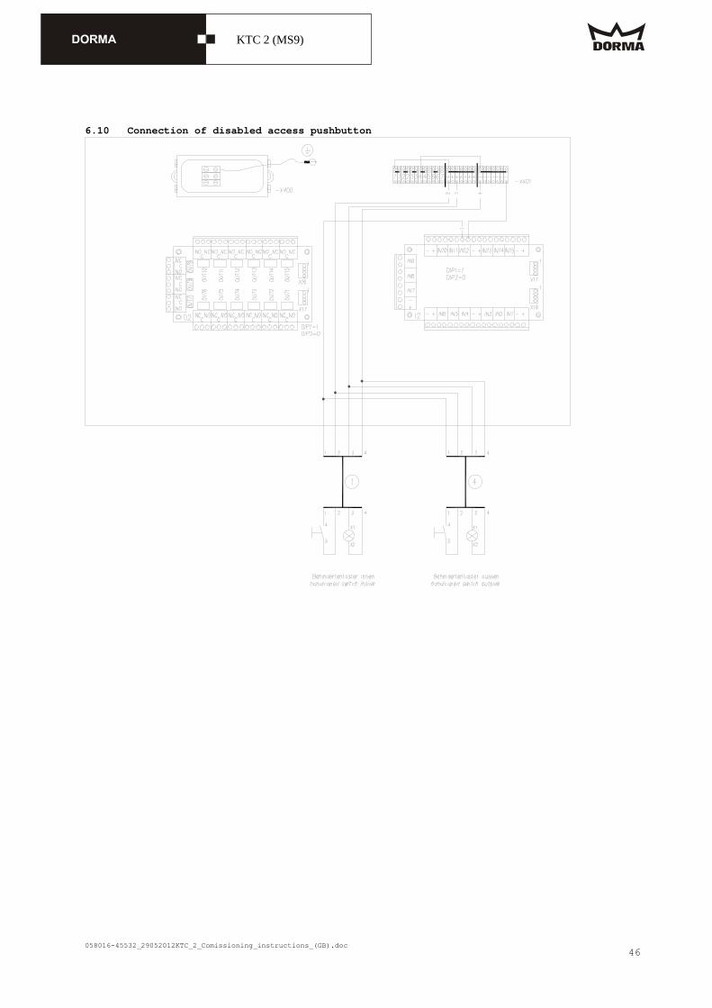
6.10 Connection of disabled access pushbutton

058016-45532_29052012KTC_2_Comissioning_instructions_(GB).doc
KTC 2 (MS9)
47
6.11 Connection of pushbutton for Emergency Stop function (inside and outside)
058016-45532_29052012KTC_2_Comissioning_instructions_(GB).doc
KTC 2 (MS9)
48
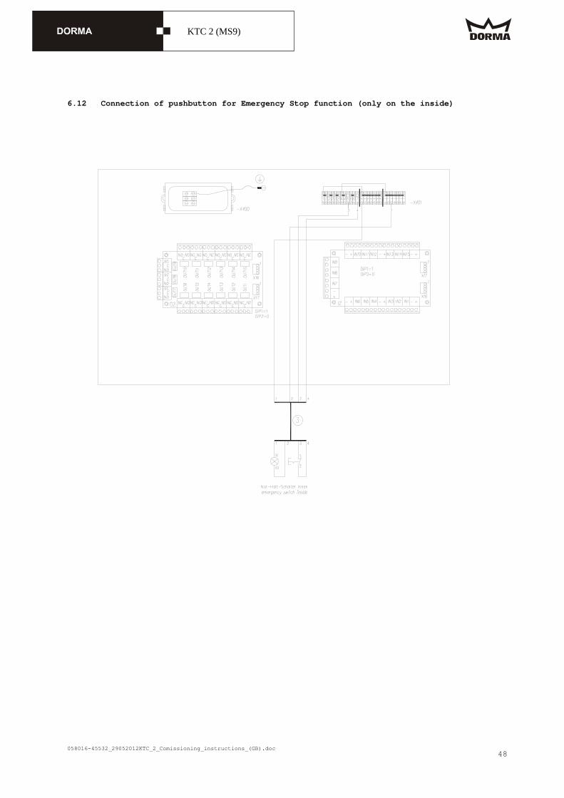
6.12 Connection of pushbutton for Emergency Stop function (only on the inside)

058016-45532_29052012KTC_2_Comissioning_instructions_(GB).doc
KTC 2 (MS9)
49
6.12 Connection of motion detectors The above connection diagram shows how to connect the P & F sensor. All sensors are connected in parallel.

058016-45532_29052012KTC_2_Comissioning_instructions_(GB).doc
KTC 2 (MS9)
50

058016-45532_29052012KTC_2_Comissioning_instructions_(GB).doc
KTC 2 (MS9)
51
6.14 Connection of radar motion detectors

058016-45532_29052012KTC_2_Comissioning_instructions_(GB).doc
KTC 2 (MS9)
52

058016-45532_29052012KTC_2_Comissioning_instructions_(GB).doc
KTC 2 (MS9)
53
6.15 Connection of fault indicator

058016-45532_29052012KTC_2_Comissioning_instructions_(GB).doc
KTC 2 (MS9)
54
6.16 Special inputs These functions are OPTIONALLY available.
058016-45532_29052012KTC_2_Comissioning_instructions_(GB).doc
KTC 2 (MS9)
55
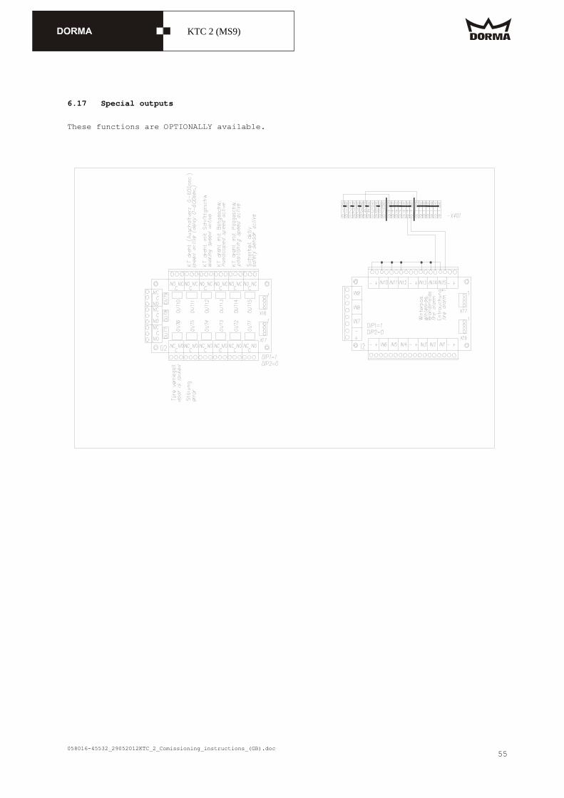
6.17 Special outputs
These functions are OPTIONALLY available.

058016-45532_29052012KTC_2_Comissioning_instructions_(GB).doc
KTC 2 (MS9)
56
7. Commissioning 7.1 Basic requirements The door system is completely mounted. The power supply is switched off. The cover for the ceiling has not been mounted. All separately supplied components are connected in accordance with the installation
instructions and the wiring diagram. The X-position sensor (including the corresponding cams for the X-position) has been
adjusted. (Clearance between sensor and cam = approx. 3 - 4 mm) When the system is in starting
position (locked position), the cam must be opposite the sensor. Activate the pushbutton for the Emergency Stop function. The door can now be moved by hand. Move door system manually to summer configuration. Check DIP-switches of DCW-components for proper setting.
DIP switches 1 + 2 of the modules have to be adjusted as follows:
Input module/output module for revolving components (1 + 2 to OFF) at -X101 control unit 1 2 DCW module
0 0
Input module/output module for static components (1 to ON, 2 to OFF) at -X401 control unit
1 2 DCW module
1 0
DIP switch "control of locking device" on -X101 control unit The DIP switch has to be adjusted to “S“. Switch on power supply. For systems with OPTIONAL sliding door, always perform commissioning of sliding door
first (see "commissioning instructions for sliding door") Measure 24 V DC voltage (X401: +/-) and adjust if required (at –G1 potentiometer)
No electric discharge lamps are installed in the close range of the door system OK not OK Check control voltage, approx. 24.5 V DC at X401 OK not OK

058016-45532_29052012KTC_2_Comissioning_instructions_(GB).doc
KTC 2 (MS9)
57
7.2 Adjustment of infrared sensors
Sensors at wings (4Safe) Designation Remote
control Value
Immunity 1 Output configuration 4 Detection hold time 3

058016-45532_29052012KTC_2_Comissioning_instructions_(GB).doc
KTC 2 (MS9)
58
Sensors at wings, AIR16 (OPTION) Adjustment of internal DIP-switches: 1 = OFF 2 = ON Adjust the detection range to approx. 500 mm above floor with the aid of the adjustment screw. Preferably select the 7th notch (inclination).
Canopy-integrated sensors, IRIS ON The inputs/outputs have to be connected as shown in the connection diagrams in case no canopy-integrated sensors are connected or if these sensors are de-installed at a later point of time. This goes for inputs and outputs 1 and 2 on the -X401 control unit. In case no sensors are connected, set jumpers at the respective inputs/outputs. Designation Remote
control Value
Output configuration 1 Maximum duration of presence detection
1
Sensitivity (presence detection)
1 - 2 (1 = DIN 18650)
Monitoring mode 1 Number of infrared light curtains
1
Installation configuration (height/frequency)
1
Redirectioning of output for safety sensor
0
Please note: Adjust the detection range of the sensor so that users cannot put their hands behind the safety contact strips at the post. Use the 1 m prism as displayed!

058016-45532_29052012KTC_2_Comissioning_instructions_(GB).doc
KTC 2 (MS9)
59
7.3 Radar motion detectors
ArtMotion

058016-45532_29052012KTC_2_Comissioning_instructions_(GB).doc
KTC 2 (MS9)
60
Easy Motion Stereo

058016-45532_29052012KTC_2_Comissioning_instructions_(GB).doc
KTC 2 (MS9)
61
7.4 DCW program switch In order to allocate the program switch to different addresses, set jumpers as follows: In case no key switch is installed, bridge inputs with key symbol!
Work on electrical equipment may only be performed by properly qualified staff (electricians). Do not work on electrical connections while the system is connected to power supply as this may cause short-circuits.
Connect system as shown in the connection diagram. Connect 24 V DC power supply.
Whenever two DCW program switches are connected to a single operator, the jumpers have to be set to different positions (H or L)
Operating instructions This program switch is only suitable for operators with DCW bus. This program switch is for products out of our System 55 product range. It fits into every standard box for flush- and surface-mounting. An individually adjustable code is required to activate the program switch. You may also protect the code with an additional key switch.
Changing the operation mode 1st Enable the program switch by entering
the code. Original setting = 1 - 1 - 1 - 1 The last four figures are always analysed as code. In case you have entered the wrong code, simply start again and type in the correct code.
The program switch is enabled as soon as the LED for the current operating code blinks.
2nd Adjust the desired operation mode with the aid of the keys.
The LED for the selected operation mode blinks.
One minute after the last key has been activated, the program switch is de-activated automatically.
Changing the code 1st Enable the program switch. 2nd Press and hold keys 1 and 2
simultaneously for approx. 3 seconds. The LEDs for keys 1 to 4 light up.
3rd Enter the new four-digit code. The code always consists of four figures from 1 to 4. You may enter the figures in any order and even use them twice.
One LED will go out for each figure you have entered.
The new code is activated as soon as all four digits of the code have been entered (all LEDs are out).
The system now indicates the current operation mode.
Unlocking via key switch In case you want to unlock the system only via the key switch, you have to change the code to 0 - 0 - 0 - 0. 1st Enable the program switch via the key
switch. 2nd Press and hold key 1 and 2
simultaneously for approx. 6 seconds. After three seconds, the LEDs 1 to 4
light up and go out after six seconds. The system now indicates the current
operation mode. The code has successfully been
adjusted to 0 - 0 - 0 - 0 and the system can only be unlocked via key switch.
If you want to change the code, the system has to be unlocked via the key switch. Please proceed as explained under "changing the code".
Please note: Whenever the program switch has been enabled via the key switch, please note that: The program switch will automatically
be disabled one minute after the last key has been activated.
The system always has to be locked via key switch.
What to do if you have forgotten the code 1st Switch off power supply. 2nd Press and hold key 1 and 3
simultaneously. 3rd Switch on power supply. 4th Release the keys. The code is now adjusted to
1 - 1 - 1 - 1.

058016-45532_29052012KTC_2_Comissioning_instructions_(GB).doc
KTC 2 (MS9)
62
The program switch is adjusted to OFF.
Power failure Following a power failure, the program switch is adjusted to the operation mode that has been activated before the power failure.
Malfunction The red LED at the program switch indicates a malfunction. The number of blinks is used as error code. For example: 1 blink = error 1, 2 blinks = error 2 etc. After a short break, the blink code starts anew.

058016-45532_29052012KTC_2_Comissioning_instructions_(GB).doc
KTC 2 (MS9)
63
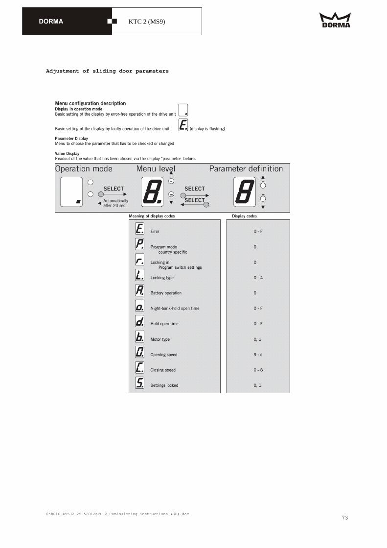
8. Adjustment at operator Use the user interface at the operator to perform the following tasks: Configuration of control unit and reading out the error log Maintenance System reset to original settings Starting a learning cycle Reset of maintenance parameters Indication of X-position (= locked position) Indication of warning messages
General information Parameter symbols: they do not blink, with decimal point Number of current position: they blink, without decimal point Current value, error symbol: they do not blink, without decimal point Initialisation, X-position: all segments light up
Displaying the learning cycle and the positioning cycle During the learning cycle and during the positioning cycle, the display shows a rotating circle.
Standard display Following the learning cycle, the positioning cycle, the initialisation, after you have quit the menu or if no key has been activated for 20 sec., the system automatically switches to standard display. Situation Display
There is at least one error. Error symbol
There is no error, but at least one warning. Warning symbol(s)
There is no error and no warning message. No symbol, a dot (not blinking).
Use "Select" key to get to parameter selection.
Parameter selection With the aid of the "+" and "-" key, you may select the different symbols for the individual parameters. The order corresponds to the order of the parameter list. If there is an unacknowledged error, a blinking "E" will appear automatically. Before adjusting any parameter, press "Select" to have the current error displayed. Press "Select" again to switch to parameter selection. Once you have left the parameter setting, the parameter selection displays the symbol of the last parameter that has been adjusted. In case there is no error message on hand, the system automatically switches to standard display after no key has been activated for 20 seconds.
058016-45532_29052012KTC_2_Comissioning_instructions_(GB).doc
KTC 2 (MS9)
64
- Error list
+ - (first
+ - (different other
.
.
.
+ - (last
+
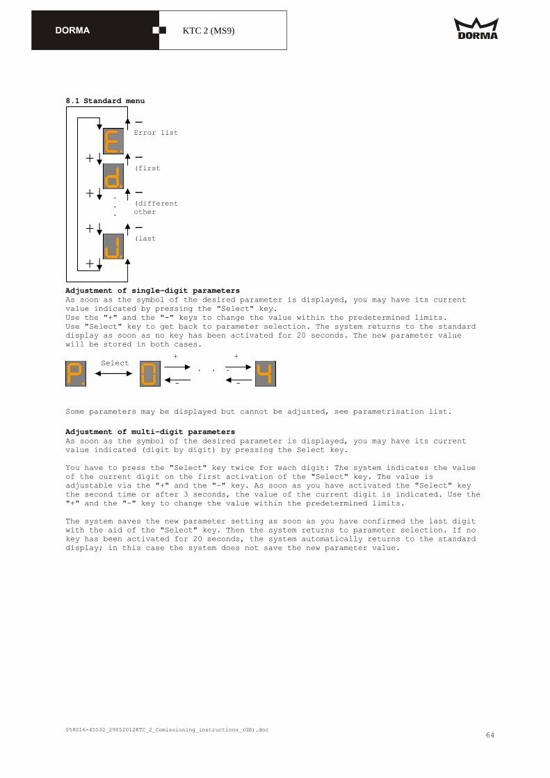
8.1 Standard menu
Adjustment of single-digit parameters As soon as the symbol of the desired parameter is displayed, you may have its current value indicated by pressing the "Select" key. Use the "+" and the "-" keys to change the value within the predetermined limits. Use "Select" key to get back to parameter selection. The system returns to the standard display as soon as no key has been activated for 20 seconds. The new parameter value will be stored in both cases.
Some parameters may be displayed but cannot be adjusted, see parametrisation list.
Adjustment of multi-digit parameters As soon as the symbol of the desired parameter is displayed, you may have its current value indicated (digit by digit) by pressing the Select key. You have to press the "Select" key twice for each digit: The system indicates the value of the current digit on the first activation of the "Select" key. The value is adjustable via the "+" and the "-" key. As soon as you have activated the "Select" key the second time or after 3 seconds, the value of the current digit is indicated. Use the "+" and the "-" key to change the value within the predetermined limits. The system saves the new parameter setting as soon as you have confirmed the last digit with the aid of the "Select" key. Then the system returns to parameter selection. If no key has been activated for 20 seconds, the system automatically returns to the standard display; in this case the system does not save the new parameter value.
Select +
-
. . .
+
-

058016-45532_29052012KTC_2_Comissioning_instructions_(GB).doc
KTC 2 (MS9)
65
8.2 Adjustment of multi-digit parameters such as SlowStop time of door panel sensor Some parameters may only be displayed but cannot be changed.
Reading-out the error log While the display shows the "error" symbol, press "Select" key to have the symbol for the current error indicated. Use the"+" and the "-" key to display all errors in the error list. Press "Select" key to return to parameter selection. The malfunction table explains the meaning of the different error symbols. When no key has been activated for 20 seconds, the system automatically switches to the standard display.
Display in the event of a malfunction
If the system detects a malfunction, an blinks on the standard display. Press "Select" key to get to the error log. Maintenance parameter selection (Maintenance parameters the control unit updates automatically) Parameter designation, text on Palm
Symbol
Description Unit Range
?
Number of revolutions 1000 5-digit, i . e. 100 million
?
Number of electric brake activations
1 8-digit, i . e. 100 million
Whenever you press and hold "+" and "-" keys simultaneously for three seconds while you are in the parameter selection, a minus will appear; as soon as you have released the keys, the display shows the symbol of the first maintenance parameter. Select the maintenance parameter with the aid of the "+" and the "-" key. Press the "Select" key several times in a row in order to have the respective value indicated digit by digit. Please note that you have to activate the "Select" key twice for each digit: The system indicates the value of the current digit on the first activation of the "Select" key. The value is adjustable via the "+" and the "-" key. As soon as you have activated the "Select" key the second time or after 3 seconds, the value of the current digit is indicated. When you have left the last digit, you will get back to the selection of the maintenance parameters. Whenever no key has been activated for 20 seconds, the current symbol disappears and is replaced by a dot. You get back to the selection of the maintenance parameters by
Select3 s
Select
Select3 s
Select
Select3 s
+ - + - + -
+ - + - + -
10 s 0.1
Select +
-
+
-
+
-
Select +
-

058016-45532_29052012KTC_2_Comissioning_instructions_(GB).doc
KTC 2 (MS9)
66
pressing the "Select" key within 20 seconds. If you do not press the key again within the above-mentioned period of time, you will automatically get back to the parameter selection. Reset of maintenance parameters In order to reset all maintenance parameters, press and hold "+" and "Select" key simultaneously for three seconds while the system is in parameter selection mode. As
soon as all parameters have been reset, the display indicates a , which disappears as soon as you release one of the two keys.

058016-45532_29052012KTC_2_Comissioning_instructions_(GB).doc
KTC 2 (MS9)
67
Parameters Parameter designation
Symbol
Description Unit Range Original setting
Palm
Central system
Learning cycle
Original
tti
Wiring
Current error status
Error list - - - - -
Door diameter
Door diameter mm 2000 .. 6500 (system learns diameter)
- - C - -
#el. locking devices
Electromechanical bolt locking device no = 0, yes = 1
0 .. 1 0 U U - C -
Hold after stop
Time until the el. brake is released after an Emergency Stop 0 = brake never released, 1 - 9 = after... sec.
sec (0 .. 9) sec 1 U U - C -
#X-Pos Auto 1 - 2
Number of starting positions in Automatic 1 or 2
2 .. 5 2 U U - C -
SlowStop canopy
SlowStop time of canopy-integrated sensors
sec (0 .. 15) sec 16 = ∞
16 U U - C -
SlowStop wing
SlowStop time of wing sensor
0.1 sec
(0 .. 15.9) sec 16.0 = ∞
16.0 U U - C -
Hold after stop
Time until the door starts after a safety stop
0.1 sec
(0 .. 9.9) sec 1.0 U U - C -
Sec. area stop
Detection range of canopy-integrated sensor in security area for SlowStop
mm (d * (pi/3) .. 500) mm
700 U U - C -
Summer configuration
Starting-positions: 0°/180°
(system reads X-positions)
- - - - U
Starting position Summer
Starting-positions: 90°/270° [0], 60°/240° [1]
0 .. 1 0 U U - C -
PosV after safety stop
Time system operates in positioning speed after leaving the stationary position following a safety stop
0.1 sec
(0.0 .. 2.9) sec
1.0 U U - C -
A/M lighting
Automatic/manual lighting control
0 ... 1 0 (auto) U U - C -
FUT warm air curtain
Follow-up time of warm air curtain
sec 0 ... 600 10 U U - C -
Caption: U = adjustable value C = resettable value - = non-adjustable value

058016-45532_29052012KTC_2_Comissioning_instructions_(GB).doc
KTC 2 (MS9)
68
8.4 Parameter adjustment of frequency converter
Frequency converter codes See appendix or order for specified parameter settings.
Adjustable parameters: CODE No.: CODE designation
C0007 Fixed configuration for digital inputs
C0010 Minimum output frequency
C0011 Maximum output frequency
C0012 Nominal run-up time
C0013 Nominal elapsed time
C0014 Operation mode (U/f-characteristic)
C0015 U/f-rated frequency
C0016 Increase in rpm
C0018 Switching frequency
C0019 Reaction point of Auto-DCB
C0021 Slip compensation
C0022 Imax-limit (motor)
C0023 Imax-limit (generator)
C0035 DCB selection
C0036 Voltage/DCB current
C0037 JOG 1 (positioning speed)
C0038 JOG 2 (low speed for disabled users)
C0039 JOG 3 (walking speed)
C0084 Stator resistance of motor
C0087 Rated speed of motor
C0088 Rated current of motor
C0089 Rated frequency of motor
C0090 Rated voltage of motor
C0091 Motor-cos C0092 Stator inductance of motor
C0106 Hold-time of auto-DCB
C0107 Hold-time of external Auto-DCB
C0119 Configuration of PTC input/...

058016-45532_29052012KTC_2_Comissioning_instructions_(GB).doc
KTC 2 (MS9)
69
8.5 Operating status indicators During operation, two LEDs indicate the operation status of the motion control (no keypad has been connected). Green LED Red LED Operation status On Off Motion control ready for operation. On On The power supply is switched on and the
automatic starting function is disabled. Blinks Off Motion control disabled Off Blinks in intervals of
1 second Malfunction, control in C0161
Off Blinks in intervals of 0.4 second
Switch off due to low voltage
Blinks rapidly Off Identification of motor parameter in progress
8.6 Changing the code values Keypad N60-0410 1st Connect keypad. 2nd Wait for 5 sec.
3rd Push key.
4th Push or until a (parameter set 2) appears. 5th Push twice until USER appears on the display.
6th Push or until ALL appears on the display.
7th Push key. 8th Push until Code appears on the display.
9th Use or to change the code. (e. g. 0039 (blinks)) 10th Push key. Now the value blinks. (e. g. 35.00 Hz)
11th Change value with or . 12th Push twice. Please note: CODES No. 7, 14 and 119 have to be confirmed with the ENTER key.
8.78 Changing the parameter set
1st Press and hold key until a appears on the display. 2nd Use or to select parameter set PS. 3rd Use or to select the parameter set you want to change.
4th Press and hold key until a appears on the display. 1
2
12
12
12
12
2
058016-45532_29052012KTC_2_Comissioning_instructions_(GB).doc
KTC 2 (MS9)
70
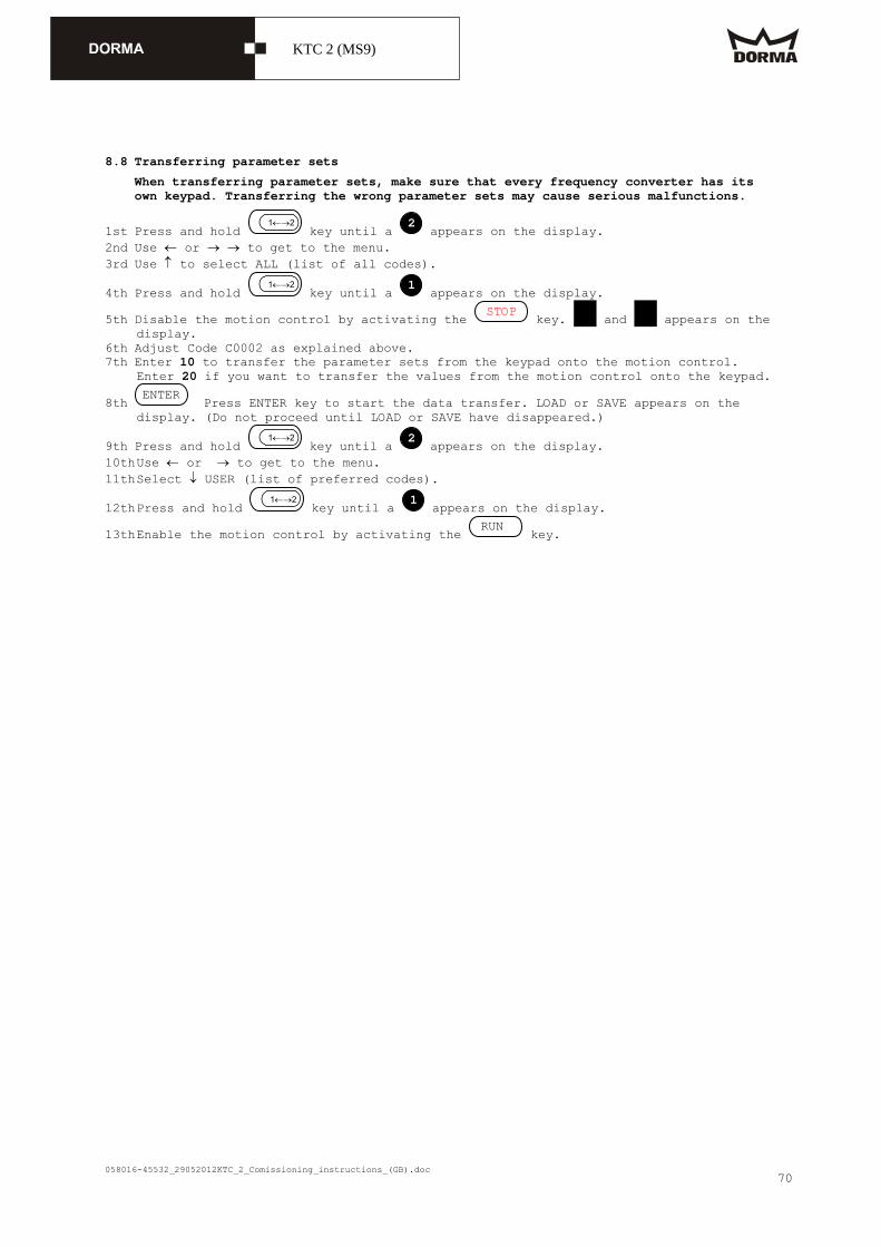
8.8 Transferring parameter sets
When transferring parameter sets, make sure that every frequency converter has its own keypad. Transferring the wrong parameter sets may cause serious malfunctions.
1st Press and hold key until a appears on the display. 2nd Use or to get to the menu. 3rd Use to select ALL (list of all codes).
4th Press and hold key until a appears on the display.
5th Disable the motion control by activating the key. RDY and IMP appears on the display.
6th Adjust Code C0002 as explained above. 7th Enter 10 to transfer the parameter sets from the keypad onto the motion control.
Enter 20 if you want to transfer the values from the motion control onto the keypad.
8th Press ENTER key to start the data transfer. LOAD or SAVE appears on the display. (Do not proceed until LOAD or SAVE have disappeared.)
9th Press and hold key until a appears on the display. 10th Use or to get to the menu. 11th Select USER (list of preferred codes).
12th Press and hold key until a appears on the display.
13th Enable the motion control by activating the key.
2
RUN
ENTER
STOP
1
1
2
12
12
12
12

058016-45532_29052012KTC_2_Comissioning_instructions_(GB).doc
KTC 2 (MS9)
71
8.9 Standard frequency converter adjustment
plant : CODE settings
Nr.: CODE designation PAR 1 PAR 2
C0007 Fixed configuration for digital inputs
1 1
C0010 Minimum output frequency 0 Hz 0 Hz
C0011 Maximum output frequency 20 Hz 5,96 Hz
C0012 Nominal run-up time 0,0 sec. 2,8 sec.
C0013 Nominal elapsed time 0 sec. 1,8 sec.
C0014 Operation mode (U/f-characteristic)
2 2
C0015 U/f-rated frequency 100 Hz 100 Hz
C0016 Increase in rpm 0 % 0 %
C0018 Switching frequency 2 2
C0019 Reaction point of Auto-DCB 20 Hz 1,0 Hz
C0021 Slip compensation 5,83 % 5,83 %
C0022 Imax-limit (motor) 150 % 75 %
C0023 Imax-limit (generator) 150 % 150 %
C0035 DCB selection 0 0
C0036 Voltage/DCB current 50 % 0 %
C0037 JOG 1 (positioning speed) 0 Hz 12,25 Hz
C0038 JOG 2 (low speed for disabled users)
0 Hz 18,38 Hz
C0039 JOG 3 (walking speed) 0 Hz 45,96 Hz
C0084 Stator resistance of motor 60 Ohm 60 Ohm
C0087 Rated speed of motor 2825 rpm/min 2825 rpm/min
C0088 Rated current of motor 3 A 3 A
C0089 Rated frequency of motor 100 Hz 100 Hz
C0090 Rated voltage of motor 230 VAC 230 VAC
C0091 Motor-cos 0,7 0,7
C0092 Stator inductance of motor 70 mH 70 mH
C0106 Hold-time of auto-DCB 1 sec. 0 sec.
C0107 Hold-time of external Auto-DCB 999 sec. 999 sec.
C0119 Configuration of PTC input/... 3 3

058016-45532_29052012KTC_2_Comissioning_instructions_(GB).doc
KTC 2 (MS9)
72
9. Commissioning of sliding door (optional)
Original settings and learning cycle In the course of the first commissioning, the system should be reset to original settings. A reset to original settings is normally only required if various settings have been changed and the door no longer works properly. If you reset the system to original settings, the adjusted country mode P = 0 remains unchanged: Activate pushbutton for Emergency Stop function Move revolving door to summer configuration. Set KT program switch to "summer configuration". The infrared sensors must be bridged (terminals 21 - 23, 26 - 28 at ES 200) or de-
activated (LEDs 1 + 2 are on). Disconnect the ES 200 basic module from power supply (if the system is equipped with
a rechargeable battery pack, it has to be disconnected from the control unit as well).
Program switch for sliding door is in "OFF" position (check). Open the door panels by 50 % (unlock the door manually, if required) Press and hold service key while plugging in the mains plug. Press and hold service key until the 7-segment display starts rotating. The door starts a closing cycle. (If the door opens, activate the "minus key (-)" on
the control unit ones in order to change the rotation direction of the motor.) The learning cycle starts from “closed” position. First the door opens at high speed (amongst others to determine the door weight), then it closes (amongst others to determine the keep-closed force). The learning cycle has been completed as soon as the 7-segment display stops rotating. In case the toothed belt derails several times during the learning cycle, re-tension the belt and reset the system to original settings. After the system has been reset to original settings, all settings that vary from the original settings (such as motor type, door type) have to be adjusted manually via the keys on the control unit or with the aid of a PDA (parametrisation). With the aid of the red "SERV key" you may trigger a Night-/Bank pulse, in order to
test the sliding door and the infrared sensors. Re-activate bridged infrared safety sensors (terminal 21 - 23; 26 - 28 at ES 200) as
required and check for proper functioning.
058016-45532_29052012KTC_2_Comissioning_instructions_(GB).doc
KTC 2 (MS9)
73
Adjustment of sliding door parameters
058016-45532_29052012KTC_2_Comissioning_instructions_(GB).doc
KTC 2 (MS9)
74
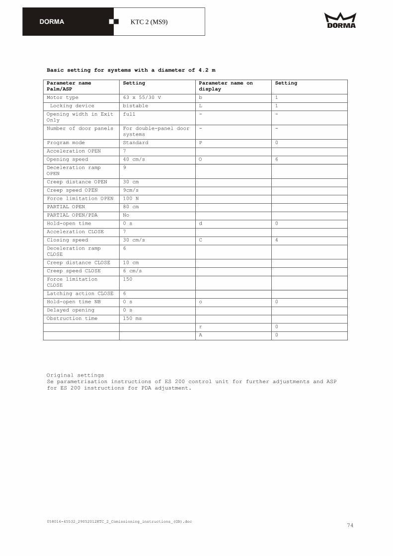
Basic setting for systems with a diameter of 4.2 m Parameter name Palm/ASP
Setting Parameter name on display
Setting
Motor type 63 x 55/30 V b 1
Locking device bistable L 1
Opening width in Exit Only
full - -
Number of door panels For double-panel door systems
- -
Program mode Standard P 0
Acceleration OPEN 7
Opening speed 40 cm/s O 6
Deceleration ramp OPEN
9
Creep distance OPEN 30 cm
Creep speed OPEN 9cm/s
Force limitation OPEN 100 N
PARTIAL OPEN 80 cm
PARTIAL OPEN/PDA No
Hold-open time 0 s d 0
Acceleration CLOSE 7
Closing speed 30 cm/s C 4
Deceleration ramp CLOSE
6
Creep distance CLOSE 10 cm
Creep speed CLOSE 6 cm/s
Force limitation CLOSE
150
Latching action CLOSE 6
Hold-open time NB 0 s o 0
Delayed opening 0 s
Obstruction time 150 ms
r 0
A 0
Original settings Se parametrisation instructions of ES 200 control unit for further adjustments and ASP for ES 200 instructions for PDA adjustment.

058016-45532_29052012KTC_2_Comissioning_instructions_(GB).doc
KTC 2 (MS9)
75

058016-45532_29052012KTC_2_Comissioning_instructions_(GB).doc
KTC 2 (MS9)
76
10. Commissioning of revolving door Starting the learning cycle During the learning cycle, the door learns the diameter of the door. The system therefore counts the incremental encoder pulses the system requires to perform a complete revolution. A full revolution corresponds to the interval between two starting point signals.
Requirements The system has not reached "locked" position (the door system is adjusted as indicated on page 13). There is no malfunction of the incremental encoder, the X-position or the frequency converter. For systems with optional sliding door, always perform commissioning of sliding door first.
Procedure The revolving door moves at positioning speed until the door has reached its "locked" position for the second time. In case a locking device has been configured, the system will demand a test. The display shows a rotating circle. The electric brake is switched off. The motor contactor is switched on.
Approach The pushbutton for the Emergency Stop function has been activated. The control unit is switched on. The program switch for the revolving door is adjusted to Automatic 1. The sliding door panels and the showcase doors are closed. The frequency converter and the control unit have been parametrised. The infrared sensors have been configured or are bridged as follows:
-X101: 23 - 24; -X101: 25 - 26; -X101: 27 - 28; -X101: 29 - 30 -X401: OUT 1 (RD) -IN 1 (GY); -X401: OUT 2 (RD) -IN 2 (GY)
In this case the cables of the corresponding sensors must not be connected to the terminal. Check if all inputs are properly connected (see "The following inputs are required to
perform a successful learning cycle."). The door system is in summer position. Press and hold "Select" key for 4 seconds. Then unlatch the pushbutton for the Emergency Stop function. The system starts the learning cycle.
Displaying the learning cycle and the positioning cycle During the learning cycle and during the positioning cycle, the display shows a rotating circle.
The door system revolves at positioning speed The door performs at least one full revolution After the door has completed the cycle it resumes function in standard mode All functions have to be checked with the aid of the original operating instructions
or the attached table. Make sure that the control unit has learned the correct diameter during the learning
cycle. Check with parameter .

058016-45532_29052012KTC_2_Comissioning_instructions_(GB).doc
KTC 2 (MS9)
77
The following inputs (marked green) are required to perform a successful learning cycle. CPU to –X101
Input module "I1" to –X101 (IN1 is located bottom right)
Input module "I2" to –X401 (IN1 is located bottom right)
Control for locking device (optional) Input Remark input module I1 Function
IN 1 Presence sensor door wing/top of showcase 1 (NC)
SlowStop
IN 2 Presence sensor door wing/top of showcase 2 (NC)
SlowStop
IN 3 Pre-detection sensor at night shield 1 (NC)
SlowStop
IN 4 Pre-detection sensor at night shield 2 (NC)
SlowStop
IN 5 Light barrier 1 (NC) Stop
IN 6 Light barrier 2 (NC) Stop
IN 7 Safety contact strips, thermo, showcase (NC)
Stop
IN 8 Sliding door is locked Stop
IN 9 Lighting on (switch on/off, external)
To switch on lighting via radio module; Adjustment via system configuration
IN 10Low battery: USV emergency power supply unit
System revolves to summer configuration when adjusted to Auto 1/2
IN 11Power failure of USV emergency power supply unit
System revolves to summer configuration when adjusted to Auto 1/2
IN 12Malfunction of sliding door Via program switch for sliding door, red LED is on
Input Remark input module I2 Function
IN 1 Canopy sensor, inside (NC) SlowStop
IN 2 Canopy sensor, outside (NC) SlowStop
IN 3 Safety contact strip, inside (NC)
Stop
IN 4 Safety contact strip, outside (NC)
Stop
IN 5 PGS OFF/locked Only if program switch is connected
IN 6 PGS Auto 1 Only if program switch is connected
IN 7 PGS Auto 2 Only if program switch is connected
IN 8 PGS Summer Only if program switch is connected
IN 9 Night-/Bank (NO) Activator for sliding door (to open the door)
IN 10Motion detector, inside (NO) Activator for revolving/sliding door (to open the door)
IN 11Motion detector, outside (NO)
Activator for revolving/sliding door (to open the door)
IN 12Disabled access pushbutton (NO)
Activator to reduce the door speed for disabled users
IN 13Winter (NO) Switch to stop the revolving door in winter/summer starting position (program switch adjusted to AUTO 1)
IN 14Fire detector input (NC) Switch for central fire detection system
IN 15Smoke extraction (NC) Switch for central fire detection system

058016-45532_29052012KTC_2_Comissioning_instructions_(GB).doc
KTC 2 (MS9)
78
Input Remark Function
IN 1 Limit switch for locking device 1 is unlocked
(NO contact) locking device is unlocked
IN 2 Limit switch for locking device 1 is locked
(NO contact) locking device is locked
IN 3 Door panel is closed Stop
OUT 1(Relay) motor of locking device
Motor of locking device 1 unlocked
OUT 2(Relay) motor of locking device
Motor of locking device 1 locked
OUT 3Wind brake control Wind brake control
OUT 4Stop

058016-45532_29052012KTC_2_Comissioning_instructions_(GB).doc
KTC 2 (MS9)
79
11. Functional testing All functions of the door system must be checked for proper functioning. Test the safety sensors with the aid of the below table (see point 14): # Sensor Activation area Activation
period Behaviour on activation
Test Allocation
1 Canopy presence sensor outside/inside
(-60° .. -500 mm) up to +60° (until the night shield has completely entered the drum wall)
Permanently; not during learning and positioning cycle
Safety SlowStop
After system was in summer configu-ation
Rigid, Slow stop
2 Safety contact strip at internal/external door post
500 mm in front of safety contact strip (until the night shield has completely entered the drum wall)
Permanently; not during learning cycle
Safety Stop After system was in summer configu-ration
Rigid, stop
3 4 6
Horizontal safety contact strip at bottom of door wing 1/2 Vertical safety contact strip at side of night shield 1/2 Limit switch for deflection device of showcase 1/2
Any door position Always Safety Stop Before the door leaves stationary position
Revolving; stop
5 Pushbutton for Emergency Stop function at external door post
Any door position Always Error stop Watchdog test
-
7 Horizontal light barrier at bottom of door wing 1/2
Any door position Permanently; not during learning cycle
Safety Stop every time the door leaves stationary position
Revolving; stop (light barrier)
8 9
Presence sensor at top of door wing/showcase 1/2 Pre-detection sensor 1/2 at revolving lower ceiling
Any door position Permanently; not during learning cycle
Safety SlowStop
Before the door leaves stationary position
Revolving; SlowStop
10
Safety sensors for sliding door
Main closing edge of sliding door
Depending on function of ES 200
Reversing ES 200 performs independent test
-

058016-45532_29052012KTC_2_Comissioning_instructions_(GB).doc
KTC 2 (MS9)
80
12. Functional characteristics 12.1 Revolving door You may select the operation modes "PGS_OFF", "PGS_Auto1", "PGS_Auto2" and "PGS_Summer" via the program switch of the revolving door.
PGS OFF If the door is not already in "locked" position, it travels to "locked" position at positioning speed and stops. The electromagnetic brake is activated. In case the system is equipped with an electromechanical bolt locking device that has already been properly adjusted, the door will lock. The lights switch off automatically. The optional sliding door operator is de-activated.
PGS Automatic 1 The locking device is not locked. The lights are switched on. The optional sliding door operator is de-activated. As soon as the activator is triggered, the door starts revolving. When one of the motion detectors is triggered:
The system revolves at walking speed as long as the detector is activated. As soon as the activators are no longer triggered, the door moves at walking speed "#X-pos. auto" (X-positions). Then the system automatically switches to positioning speed and stops as soon as it has reached the next starting position. Whenever the disabled access pushbutton has been triggered during a cycle, the driving speed is reduced to low speed for disabled users for the next 360°. If the system has already passed the starting position, the door automatically switches to positioning speed and stops as soon as it has reached the next starting position.
#X-Pos Auto 1 - 2
Number of starting positions in Automatic 1 or 2
2 = 360°
Possible starting positions:
Starting position Summer
Starting-positions: 90°/270° [0], 60°/240° [1]
0 .. 1 0 = right picture 1 = left picture
When the disabled access pushbutton is triggered:
The door moves at low speed for disabled users as long as the function of the pushbutton is activated. As soon as all activators are de-activated, the door moves the next 360° at reduced speed for disabled users. Then it automatically switches to positioning speed and stops at the next starting position.
innen
außen
innen
außen

058016-45532_29052012KTC_2_Comissioning_instructions_(GB).doc
KTC 2 (MS9)
81
PGS Automatic 2 The lights are switched on. The optional sliding door operator is de-activated. The door constantly revolves at positioning speed. The speed increases as soon as the activator is triggered. When one of the motion detectors is triggered:
The system increases speed to walking speed and remains at this speed while the motion detector is activated. As soon as the activator is no longer triggered, the door moves at walking speed "#X-pos. auto" (X-positions) and then automatically resumes operation at positioning speed. Whenever the disabled access pushbutton has been triggered during a cycle, the driving speed is reduced to "disabled speed" for the next 360°. If the system has already passed the starting positions, the door automatically switches to positioning speed.
#X-Pos Auto 1 - 2
Number of starting positions in Automatic 1 or 2
2 = 360° Walking speed
When the disabled access pushbutton is triggered:
The door moves at low speed for disabled users as long as the function of the pushbutton is activated. As soon as the activator is no longer triggered, the door moves the next 360° at reduced speed for disabled users. Then it automatically switches to positioning speed.
PGS Summer The door revolves at positioning speed and stops at the next possible summer configuration position.
12.2 Sliding door While the revolving door is operated in standard mode, the sliding door is closed and locked. The sliding door may only be operated via the ST program switch while the revolving door is adjusted to summer configuration or when the smoke and fire detector inputs are not activated and the door is in its "safe position". Following a power failure, the sliding door will resume operation in its previously adjusted operation mode. As soon as the program switch of the sliding door is adjusted to any other function but OFF, the DCW program switch of the revolving door is automatically adjusted to summer configuration and remains in this position, even if the program switch of the sliding door is adjusted to OFF. Please also consider control of the automatic sliding door.
Starting pulse (I2: IN 10 + 11) If a starting pulse is triggered while the program switch is adjusted to PGS_Auto1 or PGS_Auto2, the system will perform a standard cycle. The pulse may be triggered at: The internal motion detector input The external motion detector input The hand-held The radar motion detector input of the control unit
Night-/Bank (optional) (I2: IN 9) The Night-/Bank function is available for the following operation modes: The program switch of the revolving door is adjusted to PGS_Summer; the door is in the respective summer configuration position. The ES 200 program switch is adjusted to PGS_Off. As soon as a Night-/Bank pulse is triggered, the sliding door opens and then closes and locks on expiry of the adjusted hold-open time.
Smoke extraction (I2: IN 15) As soon as one of the smoke detector inputs is triggered, the revolving door immediately moves to its "safe position", no matter which operation mode is adjusted. When the system has reached its "safe position", the ST-PGS indicates PERMANENT OPEN and the automatic sliding door opens and remains open.

058016-45532_29052012KTC_2_Comissioning_instructions_(GB).doc
KTC 2 (MS9)
82
As soon as the input is de-activated, the control unit resumes operation in the previously adjusted operation mode.
Fire detection (I2: IN 14) On activation of the fire detector input, the revolving door moves to its "safe position" if the program switch is adjusted to PGS_Auto1, PGS_Auto2 and PGS_Summer. When the system has reached its "safe position", the ST-PGS indicates PERMANENT OPEN and the automatic sliding door opens and remains open. As soon as the input is de-activated, the control unit resumes operation in the previously adjusted operation mode.

058016-45532_29052012KTC_2_Comissioning_instructions_(GB).doc
KTC 2 (MS9)
83
Lighting Depending on the respective configuration, the lights are either switched on and off automatically (original settings) or via an external switch (optional):
Automatically The lights are only out if the door is locked in the corresponding "locked position" for a sustained period of time.
Via external switch The lights may be switched on and off via an external ON/OFF switch. Proceed as follows:

058016-45532_29052012KTC_2_Comissioning_instructions_(GB).doc
KTC 2 (MS9)
84
Disabled access pushbutton (I2: IN 12) By activating the disabled access pushbutton while the system is adjusted to "Automatic 1" and "Automatic 2", the revolving door immediately reduces speed in order to provide safe access for disabled users.

058016-45532_29052012KTC_2_Comissioning_instructions_(GB).doc
KTC 2 (MS9)
85
Winter pos (I2: IN 13) If this input is provided with an additional +24 V, the door system remains locked (while the program switch is adjusted to PGS_Auto 1) unless a starting pulse is triggered.

058016-45532_29052012KTC_2_Comissioning_instructions_(GB).doc
KTC 2 (MS9)
86
13. Further functions of revolving door 13.1 SlowStop As soon and as long as the safety sensor is activated in its respective detection area, the door speed is limited to low speed for disabled users. The speed is reduced for a fixed period of time — depending on which sensor triggered the SlowStop time (canopy-integrated sensor or wing sensor). If the safety sensors are de-activated before expiry of the SlowStop time, the door will resume operation in the previously adjusted operation mode. Please note that the system stops if the sensors are still triggered on expiry of the SlowStop time. In this case, the revolving door remains de-activated for as long as the sensors are triggered; however, at least for a certain settling time. As soon as the safety sensors are no longer triggered, the door resumes operation in the previously adjusted operation mode while the door speed is limited to positioning speed for the "posV after stop" time (positioning speed after safety stop).
SlowStop canopy
SlowStop time of canopy-integrated sensors
sec (0 .. 15) sec 16 = ∞
16
SlowStop wing
SlowStop time of wing sensor 0.1 sec
(0 .. 15.9) sec 16.0 = ∞
16.0
13.2 Obstruction stop Whenever the door speed falls below 60 mm/s — in conjunction with further conditions — and the system therefore assumes the door is obstructed, the electromagnetic brake and the frequency converter stop the door. Then the revolving door remains de-activated for at least three seconds. After this time, the door resumes operation in the adjusted operation mode while the door speed is limited to positioning speed for "PosV after stop" time (positioning speed after safety stop).
13.3 Error stop The door stops and then the system is de-activated.
13.4 Emergency stop The door stops and operates adjusted under parameter "n". Hold after stop
Time until the el. brake is released after an Emergency Stop 0 = brake never released, 1 - 9 = after... sec.
1
Tür fährt in eingestellter Betriebsart
SlowStopp-Sensor aktiv
Sicherheits-sensoren passiv
Tür ist frei
auf Behindertengeschw. begrenzenSlowStopp-Zeit starten
Warte
SlowStoppzeitabgelaufen
Sicherheits-sensoren passiv
Bei Bremsung mit E-Bremse:
Timer für PositionierV starten
Sicherheits-bereich verlassen
oderZielposition
erreicht
Sicherheits-bereich verlassen oder
Zielposition erreicht
FU bremstBeruhigungszeit startet
Beruhigungszeitabgelaufen
Geschw.> 350 mm/s
E-Bremseeinschalten

058016-45532_29052012KTC_2_Comissioning_instructions_(GB).doc
KTC 2 (MS9)
87
13.5 Safety stop The frequency converter stops the system as soon as the safety sensor is activated. The electric brake decelerates the system if the speed exceeds 350 mm/s or whenever a horizontal stop sensor at the night shield and a horizontal stop sensor at one of the door posts are triggered simultaneously. In this case, the revolving door is de-activated for as long as the sensors are triggered; however, at least for a certain settling time "Waiting after stop". As soon as the safety sensors are no longer triggered, the door resumes operation in the previously adjusted operation mode. The door speed is limited to positioning speed for "posV after stop" time (positioning speed after safety stop) whenever the system has been stopped with the aid of the electric brake. Hold after stop
Time until the door starts after a safety stop
0.1 sec
(0 .. 9.9) sec 2.0
PosV after safety stop
Time system operates in positioning speed after leaving the stationary position following a safety stop
0.1 sec
(0.0 .. 2.9) sec 1.0
13.6 Locking/unlocking
With locking device In case a locking function has been configured, the I/O-4-module controls the locking device, and reads the position of the limit switches. If no locking function has been configured, the system unlocks the electrical locking device — if available. The door does not move until the limit switches have communicated that the door is unlocked.
#el. locking devices
Electromechanical bolt locking device no = 0, yes = 1
1
Status The status of two limit switches determines the locking status. The door may either be “locked”, “unlocked” or in an “undefined status”. The system may only be locked while the door is in "locked position". The locking device must unlock automatically as soon as the door leaves "locked position".
Locking procedure The door will lock if the locking status indicates that the system is "unlocked". The locking procedure has been completed as soon as the locking status switches to “locked”. In case it takes more than three seconds until the limit switch confirms that the door is locked, the door unlocks again and then retries to lock. The system will try to lock up to three times.
Unlocking procedure The door will unlock if the locking status indicates that the system is not locked. The unlocking procedure has been completed as soon as the locking status switches to “unlocked”. In case it takes more than three seconds until the limit switch confirms that the door is "unlocked", the door locks again and then retries to unlock. The system will try to unlock up to three times.
Without locking device If the locking device cannot lock as it is defective or as no locking device has been configured or as there is no I/O-4-module or as the module is defective, the revolving door is locked in position with the aid of the electromagnetic brake. In functional respects, this means that the door is locked. The door may be opened as soon as the electromagnetic brake is switched off.
#el. locking devices
Electromechanical bolt locking device no = 0, yes = 1
0
058016-45532_29052012KTC_2_Comissioning_instructions_(GB).doc
KTC 2 (MS9)
88
Behaviour of the door if parameter "Electromech. bolt locking device” no = 0, yes = 1" is adjusted If the revolving door is in "locked position" while you adjust the parameter, the system immediately adapts the new status. This means if you switch parameter "L" from 0 to 1, the electric brake will be de-activated and the system locks with the aid of the motor. If you switch parameter "L" from 1 to 0, the electric brake is activated while the locking function of the motor is de-activated.
058016-45532_29052012KTC_2_Comissioning_instructions_(GB).doc
KTC 2 (MS9)
89
13.7 Control of automatic sliding door The control unit of the revolving door operates the automatic sliding door via the inputs of the program switch and the activator inputs. The sliding door monitors its main closing edge independent of the revolving door. The control unit of the revolving door sends the signals of the internal and external
motion detectors to the corresponding activator inputs of the sliding door. As soon and as long as the revolving door is in its "safe position" and the smoke
extraction and fire detection contacts are activated, the activation inputs of the sliding door are adjusted to PGS_Permanent_Open.
• As soon and as long as the revolving door is in its "safe position" and the smoke extraction and fire detection contacts are de-activated, all adjustments of the respective program switch are passed on to the inputs of the sliding door's control unit.
As soon and as long as the revolving door is adjusted to summer configuration and the door is in the corresponding position (without any kind of malfunction), the respective program switch adjustment for the sliding door is passed on to the inputs of the sliding door's control unit.
In any other event, the program switch inputs at the control unit of the sliding door are adjusted to PGS_Off.
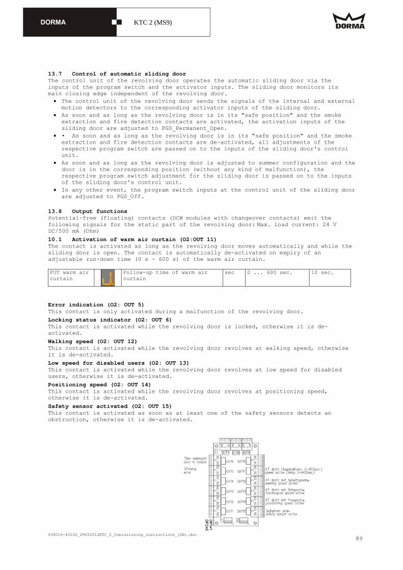
13.8 Output functions Potential-free (floating) contacts (DCW modules with changeover contacts) emit the following signals for the static part of the revolving door: Max. load current: 24 V DC/500 mA (Ohm)
10.1 Activation of warm air curtain (O2:OUT 11) The contact is activated as long as the revolving door moves automatically and while the sliding door is open. The contact is automatically de-activated on expiry of an adjustable run-down time (0 s - 600 s) of the warm air curtain. FUT warm air curtain
Follow-up time of warm air curtain
sec 0 ... 600 sec. 10 sec.
Error indication (O2: OUT 5) This contact is only activated during a malfunction of the revolving door.
Locking status indicator (O2: OUT 6) This contact is activated while the revolving door is locked, otherwise it is de-activated.
Walking speed (O2: OUT 12) This contact is activated while the revolving door revolves at walking speed, otherwise it is de-activated.
Low speed for disabled users (O2: OUT 13) This contact is activated while the revolving door revolves at low speed for disabled users, otherwise it is de-activated.
Positioning speed (O2: OUT 14) This contact is activated while the revolving door revolves at positioning speed, otherwise it is de-activated.
Safety sensor activated (O2: OUT 15) This contact is activated as soon as at least one of the safety sensors detects an obstruction, otherwise it is de-activated.

058016-45532_29052012KTC_2_Comissioning_instructions_(GB).doc
KTC 2 (MS9)
90
14. Safety equipment
Caption KTC 2 safety equipment with MS 9

058016-45532_29052012KTC_2_Comissioning_instructions_(GB).doc
KTC 2 (MS9)
91
1 Safety sensors at canopy - Adjustable activation range Sec. area stop
Detection range of canopy-integrated sensor in security area for SlowStop
mm (d * (pi/3) .. 500) mm
500 mm
- Sensor test after system was adjusted to summer configuration Function: On activation of the sensor, the turnstile reduces speed to "low speed for disabled users" and stops after the adjusted time (15 sec). As soon as the night shield enters the drum wall, the system switches to "low speed for disabled users" until the night shield has completely entered the drum wall.
2 Vertical safety contact strips (at door posts) - Activation range: 500 mm in front of safety contact strip (until the night shield has completely entered the drum wall) - Test of electronic components after system was adjusted to summer configuration Function: The turnstile stops as soon as the safety contact strips are triggered.
3 Horizontal safety contact strips at bottom of door wing - permanently activated - the electromagnetic brake is activated as soon as the sensor is triggered Function: The turnstile stops as soon as the safety contact strips are triggered.
4 Vertical safety contact strips at night shield - permanently activated - the electromagnetic brake is activated as soon as the sensor is triggered Function: The turnstile stops as soon as the safety contact strips are triggered.
5 Pushbutton for Emergency Stop function at door posts - permanently activated - As soon as the pushbutton is activated, the motor is disconnected from power supply while the electro-magnetic brake is activated. Function: The turnstile stops as soon as the pushbutton is activated.
6 Limit switch for deflection device "- as explained under "4"
7 Light barriers - as explained under "4“ The system tests the light barriers before the door leaves stationary position
8 Presence sensors at door wings and at top of showcase - permanently activated The system tests the sensors before the door leaves stationary position Function: On activation of the sensor, the turnstile reduces speed to "low speed for disabled users" and stops after the adjusted time (time is infinitely adjustable).
9 Pre-detection sensors in the revolving lower ceiling - "- as explained under "8"
10 Safety sensor for sliding door - This sensor monitors the main closing edge while the automatic sliding door is activated. The control unit of the sliding door (ES 200) performs the respective test.

058016-45532_29052012KTC_2_Comissioning_instructions_(GB).doc
KTC 2 (MS9)
92
15. Error display/warning messages 15.1 Error indication via seven-segment display at CPU "Z1"
Acknowledgement M = Manually A=Automatically
L = By performing a learning cycle - = By resetting the power supply
Name
SUB error code Sub-error name, cause, situation
Behaviour of door system The system always displays an error message.
Acknowledge-ment
No error
Watchdog error 101 Watchdog error Emergency stop M
Error of locking device
202 The door is in "locked position" and has already tried three times to unlock.
203 Both limit switches are closed
The door may only be moved by hand after it was unlocked manually.
M
Program switch error
301 Program switch of revolving door either defective or not connected
302 Revolving door program switch is connected although a DCW sliding door program switch is already connected
Door revolves to "safe position" at positioning speed
A
Sensor error 401 SlowStop test of internal canopy-
integrated sensor failed 402 SlowStop test of external canopy-
integrated sensor failed 403 Test of door wing sensor 1 failed 404 Test of door wing sensor 2 failed
The door revolves at positioning speed to "locked position" and locks although system is adjusted to "PGS_Off" In any other mode, the door revolves to "safe position" at positioning speed
405 Test failed: safety contact strip at horizontal night shield, 2 x safety contact strip at bottom of wing, limit switch for deflection device
406 Test of light barrier 1 failed 407 Test of light barrier 2 failed
Emergency stop
408 Test of pre-detection sensor at night shield 1 failed
409 Test of pre-detection sensor at night shield 2 failed
The door revolves at positioning speed to "locked position" and locks although system is adjusted to "PGS_Off" In any other mode, the door revolves to "safe position" at positioning speed
410 Test of vertical safety contact strip at internal post failed
411 Test of vertical safety contact strip at external post failed
Emergency stop
M
Incremental encoder error
501 No incremental encoder signal following three unsuccessful driving attempts due to obstructions — see "Error caused by obstruction"
502 Short-circuit between the channels 503 A channel is missing
While system is adjusted to PGS_OFF, the door travels to "locked position" and locks. In any other PGS mode: Emergency stop
M
Frequency converter error
601 Frequency converter was not ready for ≥ 6.5 seconds
Emergency stop M
CPU error 701 Defective CPU
702 Defective EEPROM (impossible to describe)
Motor will be disconnected from motor controller Error display does not blink
703 EEPROM error (incorrect checksum) Motor will be disconnected from motor controller
-
Learning cycle error
901 Too many incremental encoder pulses between two X-positions
Emergency stop L

058016-45532_29052012KTC_2_Comissioning_instructions_(GB).doc
KTC 2 (MS9)
93
Name
SUB error code Sub-error name, cause, situation
Behaviour of door system The system always displays an error message.
Acknowledge-ment
902 Too many incremental encoder pulses between two X-positions
903 Wrong rotation direction
DCW error 1001 Time-out at input module 1
1002 Time-out at output module 1 1003 Time-out at input module 2 1004 Time-out at output module 2
Emergency stop M
X-position error
1102 More than two revolutions without X-position Possible cause: Defective X-position sensor
Emergency stop M
Brake error 1201 Electrical test of electric brake failed
Door is ready for operation but only at positioning speed
M
1202 Mechanical test of electric brake failed (braking distance test)
Door is ready for operation but only at positioning speed
-
Circum ferential speed error
1301 Circumferential speed is too high Possible cause: defective frequency converter, vandalism
Emergency stop M
Obstruction error
1401 The door was blocked by an obstruction more than three times
Emergency stop M
Braking speed error
1501 Residual speed is too high when braking to stop
1502 Residual speed is too high when braking with reduced speed for disabled users
Door is ready for operation but only at positioning speed
-
Sliding door error
1701 Automatic sliding door emits error signal during standard operation while adjusted to Automatic 1 or Automatic 2 mode
1702 The manually-operated sliding door is not closed while PGS_Auto1 or BPGS_Auto2 is adjusted
The door revolves to its "safe position" at positioning speed
M
Power failure 1801 Power failure although a USV
(emergency power supply unit) is connected
While system is adjusted to PGS_Off, the door travels to "locked position" and locks The door moves to its "safe position" in any other PGS mode
A
Error Rechargeable battery pack of USV (emergency power supply unit)
1901 USV indicates an error of the rechargeable battery pack such as "low bat."
The door revolves to its "safe position" at positioning speed
M
15.2 Warnings

058016-45532_29052012KTC_2_Comissioning_instructions_(GB).doc
KTC 2 (MS9)
94
In case there is no error but a warning, the respective warning message is indicated on the display: Every three seconds, the dot (not blinking) is replaced by the error symbol for 500 msec. In case there are several warnings, they are indicated one after the other. Example Period of time [s]
Warnings 0.5 2.5 0.5 2.5 0.5 2.5 0.5 2.5
none
1
3 and G
List of warnings given
No learning cycle has been performed
Locking device registered but no IO4 module available/defective module
Emergency stop function activated
System learned program switch for sliding door, but no switch available/switch defective
Electro-magnetic brake does not work properly

058016-45532_29052012KTC_2_Comissioning_instructions_(GB).doc
KTC 2 (MS9)
95
15.3 External seven-segment display The seven-segment display is located at the internal door post. The display is controlled via the four outputs of a DCW output module. Every combination corresponds to a symbol (number or letter). Every symbol indicates a status according to the following list. If several of these errors occur at the same time, they are indicated one after the other.
OUT 10 9 8 7
Display Message Indication
- - - - 0 No message always - - - x 1 No learning cycle has been
performed always
- - x - 2 Low battery, emergency power supply unit
always
- - x x 3 Defective locking device The electromechanical locking device is connected and the learning cycle has been performed.
- x - - 4 Canopy-integrated sensors activated
always, after a learning cycle has been performed within the detection range
- x - x 5 Safety contact strips/limit switch for deflection device activated
always
- x x - 6 Safety contact strips at door posts activated
always, after a learning cycle has been performed within the detection range
- x x x 7 Wing sensors at revolving part activated
always, after a learning cycle
x - - - 8 Emergency Stop function activated
always
x - - x 9 Light barrier at revolving part activated
always, after a learning cycle
x - x - A Radar motion detector activated
always
x - x x b System revolves too fast The maximum speed is too high after the learning cycle has been performed
x x - - C Sliding door not closed always x x - x d Sensor test error always, after a learning cycle x x x - E X-position sensor not OK always, after a learning cycle x x x x F Read-in of program switch
not possible If a learnt PGS-combination has changed so that there is no clear PGS setting for the revolving or sliding door

058016-45532_29052012KTC_2_Comissioning_instructions_(GB).doc
KTC 2 (MS9)
96
15.4 Display at program switch for revolving door The red LED at the DCW program switch for the revolving door only lights up in the event of a malfunction The table will help you to analyse the respective blink code CPU display Name Malfunction indicator (LED) at electronic Program
switch
No error
Watchdog error 1
Locking device error 2
Program switch error 3
Sensor error 4
Incremental encoder error 5
Frequency converter error 6
CPU error 7
Learning cycle error 9
DCW error 10
X-position error 11
Brake error 12
Circumferential speed error 13
Obstruction error 14
Braking speed error 15
Sliding door error 17
Power failure 18
Error of USV power supply unit
19

058016-45532_29052012KTC_2_Comissioning_instructions_(GB).doc
KTC 2 (MS9)
97
15.5 Malfunction table for sliding door

058016-45532_29052012KTC_2_Comissioning_instructions_(GB).doc
KTC 2 (MS9)
98
16. Further information 16.1 Position overview Angle Position in
summer configuration
Position in
winter configuration
PGS adjustment
0° "Locked position" PGS_Off
0° X-position PGS_Auto1
60° X-position 1 PGS_Auto1
90° X-position 2 PGS_Auto1
90° Summer configuration PGS_Summer
90° "Safe position" not PGS_Off
180° X-position PGS_Auto1
240° X-position 1 PGS_Auto1
270° X-position 2 PGS_Auto1
16.2 Warning A warning informs the facility operator about possible functional impairments, malfunctions or damage. The warning disappears as soon as the cause of the possible functional impairment, malfunction or damage has been removed. In contrast to an error, the system may still be operated.
16.3 Parametrisation menus for hand-held (PDA) Settings Designation Description Unit Range # locking devices Number of locking devices (0 = no locking
device) 0 .. 1
Release electr. brake Time until the electromagnetic brake is released after an Emergency Stop via the electr. brake
sec (0 .. 9) sec
Ext. lights on Switch lighting on or off via external switch
Off On
Air curtain delay Adjustment of follow-up time for warm air curtain
sec (0 …60) sec
Driving operation Designation Description Unit Range # X-pos. auto1 - 2 Number of starting positions in Automatic 1
or 2 2 .. 5
SlowStop canopy SlowStop time of canopy-integrated sensors 0.1 s (0.0 – max.15.9, then infinitely) sec
SlowStop wing SlowStop time for door wing sensor and pre-detection sensor
sec (0 – max.15, then infinitely) sec
Hold after stop Time until the door starts after a safety stop
0.1 s (0 .. 9.9) sec
Sec. area stop Canopy sensor in security area SlowStop mm (min. 500 .. 6999 limited to max. passage width) mm
PosV after stop Time the system moves at positioning speed after leaving stationary position following a safety stop
0.1 s (0.0 .. 2.9) sec
Special functions Designation Description Unit Range Original setting Command: Reset system to original settings!
All parameters are automatically reset to original settings.
Learning cycle Command: Start learning cycle! Error reset Command: Acknowledge error! Locking procedure Command: Lock! Unlocking procedure Command: Unlock! Wing sens. act. De-activates the door wing sensors and the
pre-detection sensors in the revolving part of the door
No Yes
SCS at door act. De-activates the safety contact strips (SCS) and light barriers at the door
No Yes
Ext. SCS act. De-activates the safety contact strips (SCS) on the outside
No Yes
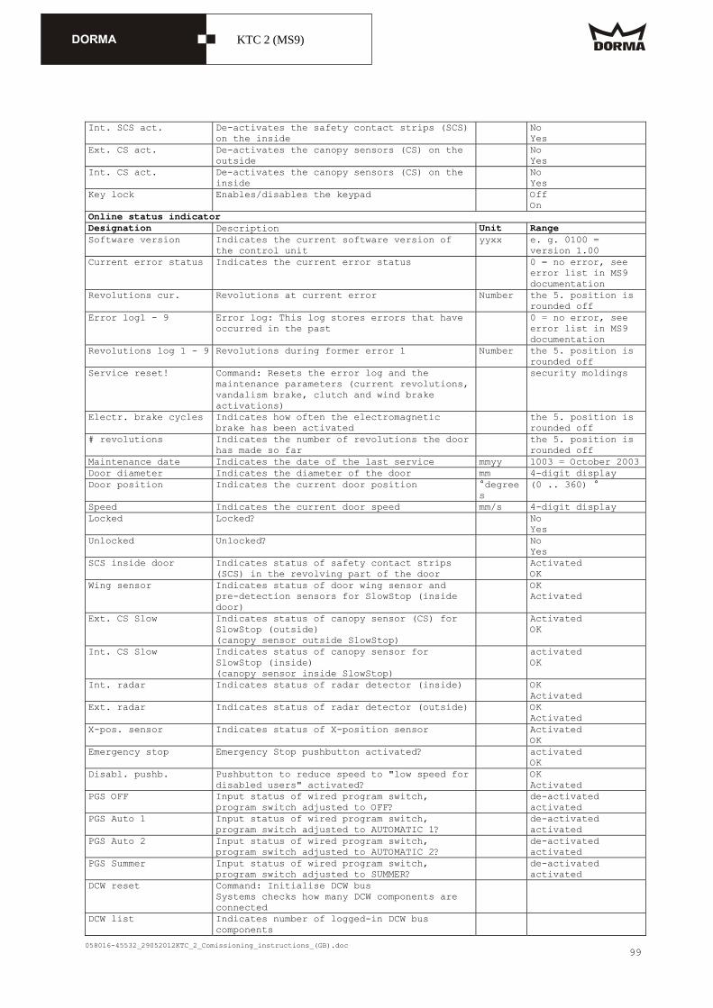
058016-45532_29052012KTC_2_Comissioning_instructions_(GB).doc
KTC 2 (MS9)
99
Int. SCS act. De-activates the safety contact strips (SCS) on the inside
No Yes
Ext. CS act. De-activates the canopy sensors (CS) on the outside
No Yes
Int. CS act. De-activates the canopy sensors (CS) on the inside
No Yes
Key lock Enables/disables the keypad Off On
Online status indicator Designation Description Unit Range Software version Indicates the current software version of
the control unit yyxx e. g. 0100 =
version 1.00 Current error status Indicates the current error status 0 = no error, see
error list in MS9 documentation
Revolutions cur. Revolutions at current error Number the 5. position is rounded off
Error log1 - 9 Error log: This log stores errors that have occurred in the past
0 = no error, see error list in MS9 documentation
Revolutions log 1 - 9 Revolutions during former error 1 Number the 5. position is rounded off
Service reset! Command: Resets the error log and the maintenance parameters (current revolutions, vandalism brake, clutch and wind brake activations)
security moldings
Electr. brake cycles Indicates how often the electromagnetic brake has been activated
the 5. position is rounded off
# revolutions Indicates the number of revolutions the door has made so far
the 5. position is rounded off
Maintenance date Indicates the date of the last service mmyy 1003 = October 2003 Door diameter Indicates the diameter of the door mm 4-digit display Door position Indicates the current door position °degree
s (0 .. 360) °
Speed Indicates the current door speed mm/s 4-digit display Locked Locked? No
Yes Unlocked Unlocked? No
Yes SCS inside door Indicates status of safety contact strips
(SCS) in the revolving part of the door Activated
OK Wing sensor Indicates status of door wing sensor and
pre-detection sensors for SlowStop (inside door)
OK Activated
Ext. CS Slow Indicates status of canopy sensor (CS) for SlowStop (outside) (canopy sensor outside SlowStop)
Activated OK
Int. CS Slow Indicates status of canopy sensor for SlowStop (inside) (canopy sensor inside SlowStop)
activated OK
Int. radar Indicates status of radar detector (inside) OK Activated
Ext. radar Indicates status of radar detector (outside) OK Activated
X-pos. sensor Indicates status of X-position sensor Activated OK
Emergency stop Emergency Stop pushbutton activated? activated OK
Disabl. pushb. Pushbutton to reduce speed to "low speed for disabled users" activated?
OK Activated
PGS OFF Input status of wired program switch, program switch adjusted to OFF?
de-activated activated
PGS Auto 1 Input status of wired program switch, program switch adjusted to AUTOMATIC 1?
de-activated activated
PGS Auto 2 Input status of wired program switch, program switch adjusted to AUTOMATIC 2?
de-activated activated
PGS Summer Input status of wired program switch, program switch adjusted to SUMMER?
de-activated activated
DCW reset Command: Initialise DCW bus Systems checks how many DCW components are connected
DCW list Indicates number of logged-in DCW bus components

058016-45532_29052012KTC_2_Comissioning_instructions_(GB).doc
KTC 2 (MS9)
100
16.4Connection handheld connection of the datacable
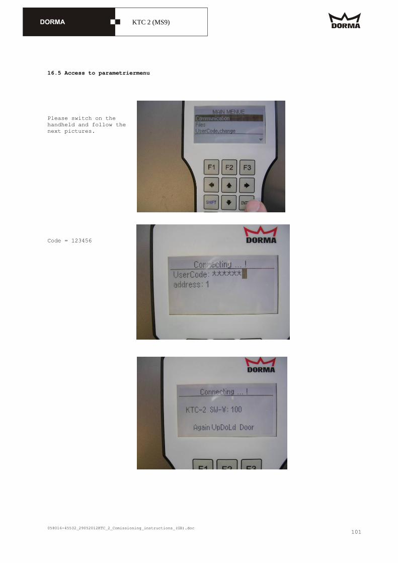
058016-45532_29052012KTC_2_Comissioning_instructions_(GB).doc
KTC 2 (MS9)
101
16.5 Access to parametriermenu Please switch on the handheld and follow the next pictures. Code = 123456

058016-45532_29052012KTC_2_Comissioning_instructions_(GB).doc
KTC 2 (MS9)
102
Download the settings from the CPU Here you can set/change the parameters

058016-45532_29052012KTC_2_Comissioning_instructions_(GB).doc
KTC 2 (MS9)
103
w w w . d o r m a . c o m
D O R M A G m b H + C o . K GDORMA Platz 1D-58256 EnnepetalTel. +49 2333/793-0Fax +49 2333/793-4950
58
01
9 4
55
32
, 1
1/1
1,
Än
der
unge
n v
orb
ehal
ten