Embed Size (px)
DESCRIPTION
article
Citation preview
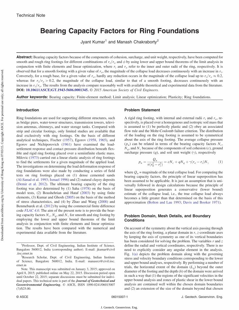
Technical Note
Bearing Capacity Factors for Ring FoundationsJyant Kumar1 and Manash Chakraborty2
Abstract: Bearing capacity factors because of the components of cohesion, surcharge, and unit weight, respectively, have been computed forsmooth and rough ring footings for different combinations of ri=ro and ϕ by using lower and upper bound theorems of the limit analysis inconjunction with finite elements and linear optimization, where ri and ro refer to the inner and outer radii of the ring, respectively. It isobserved that for a smooth footing with a given value of ro, the magnitude of the collapse load decreases continuously with an increase in ri.Conversely, for a rough base, for a given value of ro, hardly any reduction occurs in the magnitude of the collapse load up to ri=ro ≈ 0.2,whereas for ri=ro > 0.2, the magnitude of the collapse load, similar to that of a smooth footing, decreases continuously with anincrease in ri=ro. The results from the analysis compare reasonably well with available theoretical and experimental data from the literature.DOI: 10.1061/(ASCE)GT.1943-5606.0001345. © 2015 American Society of Civil Engineers.
Author keywords: Bearing capacity; Finite-element method; Limit analysis; Linear optimization; Plasticity; Ring foundations.
Introduction
Ring foundations are used for supporting different structures, suchas bridge piers, water-tower structures, transmission towers, televi-sion antennas, chimneys, and water storage tanks. Compared withstrip and circular footings, only limited studies are available thatdeal exclusively with ring footings. On the basis of differentanalytical techniques, Fischer (1957), Egorov (1958, 1965), andEgorov and Nichiporovich (1961) have examined the load-settlement response and contact pressure distribution beneath flex-ible and rigid ring footing placed over a semiinfinite elastic mass.Milovic (1973) carried out a linear elastic analysis of ring footingsto find the settlements for a given magnitude of the applied load.The investigations on determining the load deformation response ofring foundations were also made by conducting a series of fieldtests on ring footings placed on (1) dense cemented sands(Al-Sanad et al. 1993; Ismael 1996) and (2) natural clayey deposits(Demir et al. 2012). The ultimate bearing capacity of the ringfooting was also determined by (1) Saha (1978) on the basis ofmodel tests, (2) Boushehrian and Hataf (2003) by using finiteelements, (3) Kumar and Ghosh (2005) on the basis of the methodof stress characteristics, and (4) by Zhao and Wang (2008) andBenmebarek et al. (2012) by using the commercial finite differencecode FLAC 4.0. The aim of the present note is to provide the bear-ing capacity factors Nc, Nq, and Nγ for smooth and ring footing byemploying the lower and upper bound theorems of the limitanalysis in conjunction with finite elements and linear optimiza-tion. The results have been compared with the numerical andexperimental data available from the literature.
Problem Statement
A rigid ring footing, with internal and external radii ri and ro, re-spectively, is placed over a homogenous and isotropic soil mass thatis assumed to (1) be perfectly plastic and (2) obey an associatedflow rule and the Mohr-Coulomb failure criterion. The distributionof the loading on the ring footing is assumed to be symmetricalabout the axis of the ring footing. The average collapse pressure(pu) can be related in terms of the bearing capacity factors Nc,Nq, and Nγ because of the components of soil cohesion (c), groundsurcharge pressure (q), and soil unit weight (γ), respectively
pu ¼Qu
πðr20 − r2i Þ¼ cNc þ qNq þ γðro − riÞNγ ð1Þ
whereQu = magnitude of the total collapse load. For computing thebearing capacity factors, the principle of linear superposition hasbeen assumed to be applicable. It is just an assumption that is uni-versally followed in design calculations because the principle oflinear superposition generates a conservative (lower bound)estimate of the collapse load, i.e., the true collapse load alwaysbecomes a little greater than that determined on the basis of thisapproximation (Bolton and Lau 1993; Davis and Booker 1971).
Problem Domain, Mesh Details, and BoundaryConditions
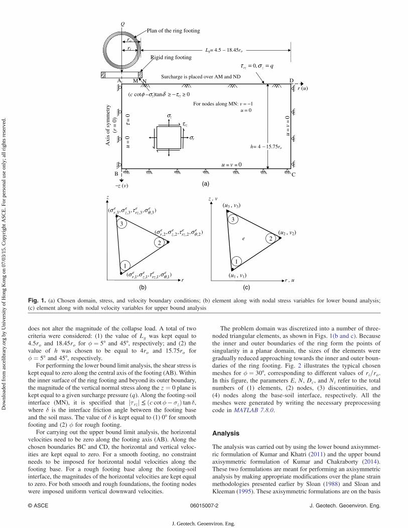
On account of the symmetry about the vertical axis passing throughthe axis of the ring footing, a planar domain in r, z-coordinate axesby keeping the axis of symmetry as one of its vertical boundarieshas been considered for solving the problem. The variables r and zdefine the radial and vertical coordinates, respectively. There is noneed to explicitly consider any angular element in the analysis.Fig. 1(a) depicts the problem domain along with the governingstress and velocity boundary conditions corresponding to the lowerand upper bound analyses, respectively. By performing a number oftrials, the horizontal extent of the domain (Lg) beyond the outerdiameter of the footing and the depth (h) of the domain were arrivedin such a way that (1) the regions of the significant velocities in theupper bound analysis and zones of plastic shear in the lower boundanalysis are contained well within the chosen domain boundariesand (2) an extension of the size of the domain beyond that chosen
1Professor, Dept. of Civil Engineering, Indian Institute of Science,Bangalore 560012, India (corresponding author). E-mail: [email protected]
2Research Scholar, Dept. of Civil Engineering, Indian Instituteof Science, Bangalore 560012, India. E-mail: [email protected]
Note. This manuscript was submitted on January 3, 2015; approved onApril 8, 2015; published online on May 22, 2015. Discussion period openuntil October 22, 2015; separate discussions must be submitted for indivi-dual papers. This technical note is part of the Journal of Geotechnical andGeoenvironmental Engineering, © ASCE, ISSN 1090-0241/06015007(7)/$25.00.
© ASCE 06015007-1 J. Geotech. Geoenviron. Eng.
J. Geotech. Geoenviron. Eng.
Dow
nloa
ded
from
asc
elib
rary
.org
by
Uni
vers
ity o
f H
ong
Kon
g on
07/
03/1
5. C
opyr
ight
ASC
E. F
or p
erso
nal u
se o
nly;
all
righ
ts r
eser
ved.
does not alter the magnitude of the collapse load. A total of twocriteria were considered: (1) the value of Lg was kept equal to4.5ro and 18.45ro for ϕ ¼ 5° and 45°, respectively; and (2) thevalue of h was chosen to be equal to 4ro and 15.75ro forϕ ¼ 5° and 45°, respectively.
For performing the lower bound limit analysis, the shear stress iskept equal to zero along the central axis of the footing (AB). Withinthe inner surface of the ring footing and beyond its outer boundary,the magnitude of the vertical normal stress along the z ¼ 0 plane iskept equal to a given surcharge pressure (q). Along the footing-soilinterface (MN), it is specified that jτ rzj ≤ ðc cotϕ − σzÞ tan δ,where δ is the interface friction angle between the footing baseand the soil mass. The value of δ is kept equal to (1) 0° for smoothfooting and (2) ϕ for rough footing.
For carrying out the upper bound limit analysis, the horizontalvelocities need to be zero along the footing axis (AB). Along thechosen boundaries BC and CD, the horizontal and vertical veloc-ities are kept equal to zero. For a smooth footing, no constraintneeds to be imposed for horizontal nodal velocities along thefooting base. For a rough footing base along the footing-soilinterface, the magnitudes of the horizontal velocities are kept equalto zero. For both smooth and rough foundations, the footing nodeswere imposed uniform vertical downward velocities.
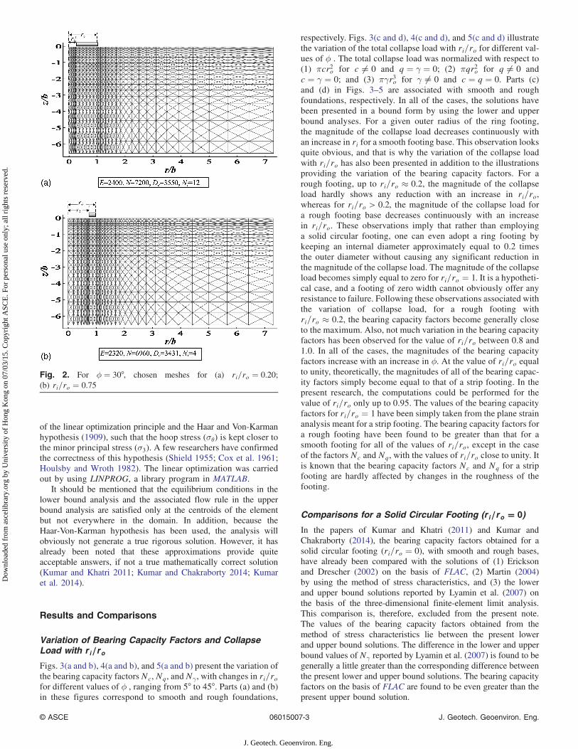
The problem domain was discretized into a number of three-noded triangular elements, as shown in Figs. 1(b and c). Becausethe inner and outer boundaries of the ring form the points ofsingularity in a planar domain, the sizes of the elements weregradually reduced approaching towards the inner and outer boun-daries of the ring footing. Fig. 2 illustrates the typical chosenmeshes for ϕ ¼ 30°, corresponding to different values of ri=ro.In this figure, the parameters E, N, Dc, and Ni refer to the totalnumbers of (1) elements, (2) nodes, (3) discontinuities, and(4) nodes along the base-soil interface, respectively. All themeshes were generated by writing the necessary preprocessingcode in MATLAB 7.8.0.
Analysis
The analysis was carried out by using the lower bound axisymmet-ric formulation of Kumar and Khatri (2011) and the upper boundaxisymmetric formulation of Kumar and Chakraborty (2014).These two formulations are meant for performing an axisymmetricanalysis by making appropriate modifications over the plane strainmethodologies presented earlier by Sloan (1988) and Sloan andKleeman (1995). These axisymmetric formulations are on the basis
r
),,( 3,3,3,3, , eerz
ez
er θστσσ
2
z , v(u3 , v3)
(u1 , v1)
(u2 , v2)e
),,( 2,2,2,2, , eerz
ez
er θστσσ
1
3
),,( 1,1,1,1, , eerz
ez
er θστσσ
z
2
1
3
r , u
−z (v)
Axi
s of
sym
met
ry
(r
= 0
)
r (u)
u =
0
u = v = 0
u=
v =
0
Rigid ring footing
qzrz == στ ,0
τ=
0
Plan of the ring footing
A
B C
D M N
For nodes along MN: v = −1 u = 0
Surcharge is placed over AM and ND
Lg= 4.5 − 18.45ro
h= 4 − 15.75ro
ri
ro
(c cotφ –σz)tanδ −τrz 0
σr
σz
τrz
(a)
(b) (c)
Q
Fig. 1. (a) Chosen domain, stress, and velocity boundary conditions; (b) element along with nodal stress variables for lower bound analysis;(c) element along with nodal velocity variables for upper bound analysis
© ASCE 06015007-2 J. Geotech. Geoenviron. Eng.
J. Geotech. Geoenviron. Eng.
Dow
nloa
ded
from
asc
elib
rary
.org
by
Uni
vers
ity o
f H
ong
Kon
g on
07/
03/1
5. C
opyr
ight
ASC
E. F
or p
erso
nal u
se o
nly;
all
righ
ts r
eser
ved.
of the linear optimization principle and the Haar and Von-Karmanhypothesis (1909), such that the hoop stress (σθ) is kept closer tothe minor principal stress (σ3). A few researchers have confirmedthe correctness of this hypothesis (Shield 1955; Cox et al. 1961;Houlsby and Wroth 1982). The linear optimization was carriedout by using LINPROG, a library program in MATLAB.
It should be mentioned that the equilibrium conditions in thelower bound analysis and the associated flow rule in the upperbound analysis are satisfied only at the centroids of the elementbut not everywhere in the domain. In addition, because theHaar-Von-Karman hypothesis has been used, the analysis willobviously not generate a true rigorous solution. However, it hasalready been noted that these approximations provide quiteacceptable answers, if not a true mathematically correct solution(Kumar and Khatri 2011; Kumar and Chakraborty 2014; Kumaret al. 2014).
Results and Comparisons
Variation of Bearing Capacity Factors and CollapseLoad with r i=ro
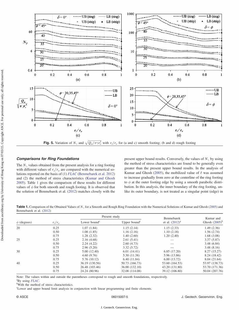
Figs. 3(a and b), 4(a and b), and 5(a and b) present the variation ofthe bearing capacity factors Nc, Nq, and Nγ , with changes in ri=rofor different values of ϕ , ranging from 5° to 45°. Parts (a) and (b)in these figures correspond to smooth and rough foundations,
respectively. Figs. 3(c and d), 4(c and d), and 5(c and d) illustratethe variation of the total collapse load with ri=ro for different val-ues of ϕ . The total collapse load was normalized with respect to(1) πcr2o for c ≠ 0 and q ¼ γ ¼ 0; (2) πqr2o for q ≠ 0 andc ¼ γ ¼ 0; and (3) πγr3o for γ ≠ 0 and c ¼ q ¼ 0. Parts (c)and (d) in Figs. 3–5 are associated with smooth and roughfoundations, respectively. In all of the cases, the solutions havebeen presented in a bound form by using the lower and upperbound analyses. For a given outer radius of the ring footing,the magnitude of the collapse load decreases continuously withan increase in ri for a smooth footing base. This observation looksquite obvious, and that is why the variation of the collapse loadwith ri=ro has also been presented in addition to the illustrationsproviding the variation of the bearing capacity factors. For arough footing, up to ri=ro ≈ 0.2, the magnitude of the collapseload hardly shows any reduction with an increase in ri=ro,whereas for ri=ro > 0.2, the magnitude of the collapse load fora rough footing base decreases continuously with an increasein ri=ro. These observations imply that rather than employinga solid circular footing, one can even adopt a ring footing bykeeping an internal diameter approximately equal to 0.2 timesthe outer diameter without causing any significant reduction inthe magnitude of the collapse load. The magnitude of the collapseload becomes simply equal to zero for ri=ro ¼ 1. It is a hypotheti-cal case, and a footing of zero width cannot obviously offer anyresistance to failure. Following these observations associated withthe variation of collapse load, for a rough footing withri=ro ≈ 0.2, the bearing capacity factors become generally closeto the maximum. Also, not much variation in the bearing capacityfactors has been observed for the value of ri=ro between 0.8 and1.0. In all of the cases, the magnitudes of the bearing capacityfactors increase with an increase in ϕ. At the value of ri=ro equalto unity, theoretically, the magnitudes of all of the bearing capac-ity factors simply become equal to that of a strip footing. In thepresent research, the computations could be performed for thevalue of ri=ro only up to 0.95. The values of the bearing capacityfactors for ri=ro ¼ 1 have been simply taken from the plane strainanalysis meant for a strip footing. The bearing capacity factors fora rough footing have been found to be greater than that for asmooth footing for all of the values of ri=ro, except in the caseof the factors Nc and Nq, with the values of ri=ro close to unity. Itis known that the bearing capacity factors Nc and Nq for a stripfooting are hardly affected by changes in the roughness of thefooting.
Comparisons for a Solid Circular Footing (r i=ro � 0)
In the papers of Kumar and Khatri (2011) and Kumar andChakraborty (2014), the bearing capacity factors obtained for asolid circular footing (ri=ro ¼ 0), with smooth and rough bases,have already been compared with the solutions of (1) Ericksonand Drescher (2002) on the basis of FLAC, (2) Martin (2004)by using the method of stress characteristics, and (3) the lowerand upper bound solutions reported by Lyamin et al. (2007) onthe basis of the three-dimensional finite-element limit analysis.This comparison is, therefore, excluded from the present note.The values of the bearing capacity factors obtained from themethod of stress characteristics lie between the present lowerand upper bound solutions. The difference in the lower and upperbound values of Nγ reported by Lyamin et al. (2007) is found to begenerally a little greater than the corresponding difference betweenthe present lower and upper bound solutions. The bearing capacityfactors on the basis of FLAC are found to be even greater than thepresent upper bound solution.
Fig. 2. For ϕ ¼ 30°, chosen meshes for (a) ri=ro ¼ 0.20;(b) ri=ro ¼ 0.75
© ASCE 06015007-3 J. Geotech. Geoenviron. Eng.
J. Geotech. Geoenviron. Eng.
Dow
nloa
ded
from
asc
elib
rary
.org
by
Uni
vers
ity o
f H
ong
Kon
g on
07/
03/1
5. C
opyr
ight
ASC
E. F
or p
erso
nal u
se o
nly;
all
righ
ts r
eser
ved.
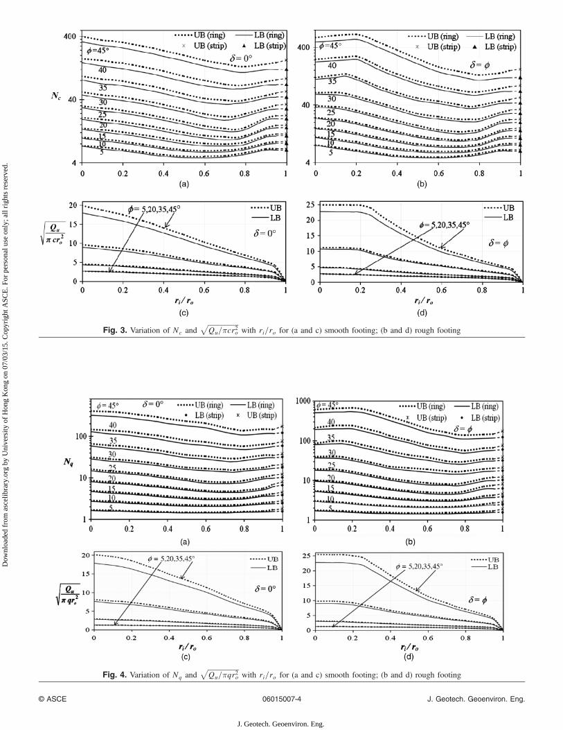
Fig. 3. Variation of Nc andffiffiffiffiffiffiffiffiffiffiffiffiffiffiffiffiffiffiQu=πcr2o
pwith ri=ro for (a and c) smooth footing; (b and d) rough footing
Fig. 4. Variation of Nq andffiffiffiffiffiffiffiffiffiffiffiffiffiffiffiffiffiffiQu=πqr2o
pwith ri=ro for (a and c) smooth footing; (b and d) rough footing
© ASCE 06015007-4 J. Geotech. Geoenviron. Eng.
J. Geotech. Geoenviron. Eng.
Dow
nloa
ded
from
asc
elib
rary
.org
by
Uni
vers
ity o
f H
ong
Kon
g on
07/
03/1
5. C
opyr
ight
ASC
E. F
or p
erso
nal u
se o
nly;
all
righ
ts r
eser
ved.
Comparisons for Ring Foundations
The Nγ values obtained from the present analysis for a ring footingwith different values of ri=ro are compared with the numerical so-lutions reported on the basis of (1) FLAC (Benmebarek et al. 2012)and (2) the method of stress characteristics (Kumar and Ghosh2005). Table 1 gives the comparison of these results for differentvalues of ϕ for both smooth and rough footing. It is observed thatthe solution of Benmebarek et al. (2012) matches closely with the
present upper bound results. Conversely, the values of Nγ by usingthe method of stress characteristics are found to be generally evengreater than the present upper bound results. In the analysis ofKumar and Ghosh (2005), the mobilized value of δ was assumedto increase gradually from zero at the centerline of the ring footingto ϕ at the outer footing edge by using a smooth parabolic distri-bution. In this analysis, the inner boundary of the ring footing, un-like its outer boundary, is not treated as a singular point (edge) in
Fig. 5. Variation of Nγ andffiffiffiffiffiffiffiffiffiffiffiffiffiffiffiffiffiffiQu=πγr3o
pwith ri=ro for (a and c) smooth footing; (b and d) rough footing
Table 1. Comparison of the Obtained Values of Nγ for a Smooth and Rough Ring Foundation with the Numerical Solutions of Kumar and Ghosh (2005) andBenmebarek et al. (2012)
ϕ (degrees) ri=ro
Present study Benmebareket al. (2012)a
Kumar andGhosh (2005)bLower boundc Upper boundc
20 0.25 1.07 (1.84) 1.15 (2.14) 1.15 (2.33) 1.49 (2.36)0.50 1.08 (1.85) 1.16 (2.16) 1.10 (2.18) 1.56 (2.74)0.75 1.28 (2.32) 1.40 (2.60) 1.20 (2.40) 1.68 (3.08)
25 0.25 2.16 (4.68) 2.61 (5.41) — 3.37 (5.87)0.50 2.24 (4.22) 2.60 (4.73) — 3.48 (6.84)0.75 2.96 (5.20) 3.32 (5.72) — 3.48 (8.16)
30 0.25 5.00 (12.40) 6.01 (14.41) 6.85 (17.20) 8.27 (15.27)0.50 4.60 (9.76) 5.30 (11.38) 5.96 (13.86) 8.24 (18.42)0.75 5.76 (10.12) 6.40 (11.84) 6.00 (13.72) 8.04 (21.64)
40 0.25 36.19 (130.56) 50.73 (166.73) 53.60 (164.53) 53.97 (138.73)0.50 26.48 (103.46) 36.00 (132.10) 43.20 (131.80) 53.70 (171.36)0.75 24.24 (80.96) 32.08 (114.08) 39.12 (106.80) 50.04 (207.76)
Note: The values within and outside the parentheses correspond to rough and smooth foundations, respectively.aBy using FLAC.bWith the method of stress characteristics.cLower and upper bound limit analysis in conjunction with linear programming and finite elements.
© ASCE 06015007-5 J. Geotech. Geoenviron. Eng.
J. Geotech. Geoenviron. Eng.
Dow
nloa
ded
from
asc
elib
rary
.org
by
Uni
vers
ity o
f H
ong
Kon
g on
07/
03/1
5. C
opyr
ight
ASC
E. F
or p
erso
nal u
se o
nly;
all
righ
ts r
eser
ved.
the planar domain. The distribution of the pressure on the ring foot-ing was simply arrived at by considering the ring as a part of thesolid circular footing without considering any change in its pressuredistribution over its annular region. As a result, the method of thecharacteristic in this manner will not provide a true solution. This isthe reason for the difference between the present solution and thatreported by using the method of stress characteristics.
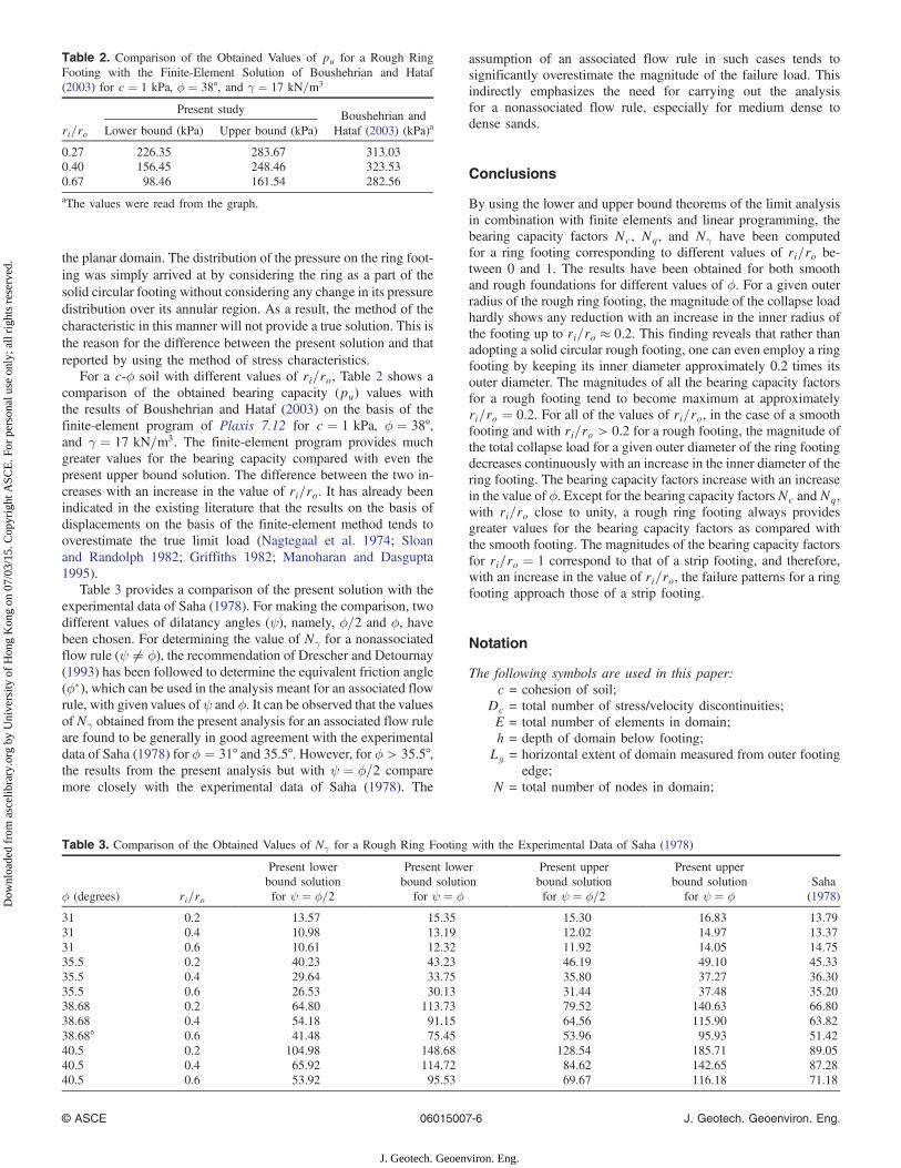
For a c-ϕ soil with different values of ri=ro, Table 2 shows acomparison of the obtained bearing capacity (pu) values withthe results of Boushehrian and Hataf (2003) on the basis of thefinite-element program of Plaxis 7.12 for c ¼ 1 kPa, ϕ ¼ 38°,and γ ¼ 17 kN=m3. The finite-element program provides muchgreater values for the bearing capacity compared with even thepresent upper bound solution. The difference between the two in-creases with an increase in the value of ri=ro. It has already beenindicated in the existing literature that the results on the basis ofdisplacements on the basis of the finite-element method tends tooverestimate the true limit load (Nagtegaal et al. 1974; Sloanand Randolph 1982; Griffiths 1982; Manoharan and Dasgupta1995).
Table 3 provides a comparison of the present solution with theexperimental data of Saha (1978). For making the comparison, twodifferent values of dilatancy angles (ψ), namely, ϕ=2 and ϕ, havebeen chosen. For determining the value of Nγ for a nonassociatedflow rule (ψ ≠ ϕ), the recommendation of Drescher and Detournay(1993) has been followed to determine the equivalent friction angle(ϕ�), which can be used in the analysis meant for an associated flowrule, with given values of ψ and ϕ. It can be observed that the valuesof Nγ obtained from the present analysis for an associated flow ruleare found to be generally in good agreement with the experimentaldata of Saha (1978) for ϕ ¼ 31° and 35.5°. However, for ϕ > 35.5°,the results from the present analysis but with ψ ¼ ϕ=2 comparemore closely with the experimental data of Saha (1978). The
assumption of an associated flow rule in such cases tends tosignificantly overestimate the magnitude of the failure load. Thisindirectly emphasizes the need for carrying out the analysisfor a nonassociated flow rule, especially for medium dense todense sands.
Conclusions
By using the lower and upper bound theorems of the limit analysisin combination with finite elements and linear programming, thebearing capacity factors Nc, Nq, and Nγ have been computedfor a ring footing corresponding to different values of ri=ro be-tween 0 and 1. The results have been obtained for both smoothand rough foundations for different values of ϕ. For a given outerradius of the rough ring footing, the magnitude of the collapse loadhardly shows any reduction with an increase in the inner radius ofthe footing up to ri=ro ≈ 0.2. This finding reveals that rather thanadopting a solid circular rough footing, one can even employ a ringfooting by keeping its inner diameter approximately 0.2 times itsouter diameter. The magnitudes of all the bearing capacity factorsfor a rough footing tend to become maximum at approximatelyri=ro ¼ 0.2. For all of the values of ri=ro, in the case of a smoothfooting and with ri=ro > 0.2 for a rough footing, the magnitude ofthe total collapse load for a given outer diameter of the ring footingdecreases continuously with an increase in the inner diameter of thering footing. The bearing capacity factors increase with an increasein the value of ϕ. Except for the bearing capacity factorsNc andNq,with ri=ro close to unity, a rough ring footing always providesgreater values for the bearing capacity factors as compared withthe smooth footing. The magnitudes of the bearing capacity factorsfor ri=ro ¼ 1 correspond to that of a strip footing, and therefore,with an increase in the value of ri=ro, the failure patterns for a ringfooting approach those of a strip footing.
Notation
The following symbols are used in this paper:c = cohesion of soil;
Dc = total number of stress/velocity discontinuities;E = total number of elements in domain;h = depth of domain below footing;Lg = horizontal extent of domain measured from outer footing
edge;N = total number of nodes in domain;
Table 2. Comparison of the Obtained Values of pu for a Rough RingFooting with the Finite-Element Solution of Boushehrian and Hataf(2003) for c ¼ 1 kPa, ϕ ¼ 38°, and γ ¼ 17 kN=m3
ri=ro
Present study Boushehrian andHataf (2003) (kPa)aLower bound (kPa) Upper bound (kPa)
0.27 226.35 283.67 313.030.40 156.45 248.46 323.530.67 98.46 161.54 282.56aThe values were read from the graph.
Table 3. Comparison of the Obtained Values of Nγ for a Rough Ring Footing with the Experimental Data of Saha (1978)
ϕ (degrees) ri=ro
Present lowerbound solutionfor ψ ¼ ϕ=2
Present lowerbound solution
for ψ ¼ ϕ
Present upperbound solutionfor ψ ¼ ϕ=2
Present upperbound solution
for ψ ¼ ϕSaha(1978)
31 0.2 13.57 15.35 15.30 16.83 13.7931 0.4 10.98 13.19 12.02 14.97 13.3731 0.6 10.61 12.32 11.92 14.05 14.7535.5 0.2 40.23 43.23 46.19 49.10 45.3335.5 0.4 29.64 33.75 35.80 37.27 36.3035.5 0.6 26.53 30.13 31.44 37.48 35.2038.68 0.2 64.80 113.73 79.52 140.63 66.8038.68 0.4 54.18 91.15 64.56 115.90 63.8238.68° 0.6 41.48 75.45 53.96 95.93 51.4240.5 0.2 104.98 148.68 128.54 185.71 89.0540.5 0.4 65.92 114.72 84.62 142.65 87.2840.5 0.6 53.92 95.53 69.67 116.18 71.18
© ASCE 06015007-6 J. Geotech. Geoenviron. Eng.
J. Geotech. Geoenviron. Eng.
Dow
nloa
ded
from
asc
elib
rary
.org
by
Uni
vers
ity o
f H
ong
Kon
g on
07/
03/1
5. C
opyr
ight
ASC
E. F
or p
erso
nal u
se o
nly;
all
righ
ts r
eser
ved.
Nc = bearing capacity factor because of soil cohesion;Ni = total number of nodes along footing-soil interface;Nq = bearing capacity factor because of surcharge pressure;Nγ = bearing capacity factor because of unit weight of soil;pu = average ultimate pressure on footing;Qu = magnitude of resultant collapse load;q = surcharge pressure;ri = internal radius of ring footing;ro = external radius of ring footing;γ = unit weight of soil;δ = interface friction angle between footing and adjoining soil
mass;σz = normal stress in z-direction;σ3 = minor principal stress;σθ = circumferential stress;τ rz = shear stress in r, z-plane;ϕ = internal friction angle of soil;ϕ� = equivalent friction angle; andψ = dilation angle.
References
Al-Sanad, H. A., Ismael, N. F., and Brenner, R. P. (1993). “Settlementof circular and ring plates in very dense calcareous sands.” J. Geotech.Eng., 10.1061/(ASCE)0733-9410(1993)119:4(622), 622–638.
Benmebarek, S., Remadna, M. S., Benmebarek, N., and Belounar, L.(2012). “Numerical evaluation of bearing capacity factor Nγ of ringfootings.” Comput. Geotech., 44, 132–138.
Bolton, M. D., and Lau, C. K. (1993). “Vertical bearing capacity factorsfor circular and strip footings on Mohr-Coulomb soil.” Can. Geotech.J., 30(6), 1024–1033.
Boushehrian, J. H., and Hataf, N. (2003). “Experimental and numericalinvestigation of the bearing capacity of model circular and ring footingson reinforced sand.” Geotext. Geomembr., 21(4), 241–256.
Cox, A. D., Eason, G., and Hopkins, H. G. (1961). “Axially symmetricplastic deformation in soils.” Phil. Trans. Roy. Soc. A London Math.Phys. Eng. Sci., 254(1036), 1–45.
Davis, E. H., and Booker, J. (1971). “The bearing capacity of strip footingsfrom the standpoint of plasticity theory.” Proc., 1st Australian-New Zealand Conf. in Geomechanics, Melbourne, Australia, 276–282.
Demir, A., Örnek, M., Laman, M., and Yildiz, A. (2012). “Analysis of ringfootings using field test results.” Proc., 3rd Int. Conf. of New Develop-ments in Soil Mechanics and Geotechnical Engineering, Nicosia,Northern Cyprus, 179–184.
Drescher, A., and Detournay, E. (1993). “Limit load in translationalfailure mechanisms for associative and non-associative materials.”Géotechnique, 43(3), 443–456.
Egorov, K. E. (1958). “Problem of calculating the base under a foundationwith a lower surface of ring shape.” NII Osnovanii Soil. Mech.Gosstroiizdat., 34.
Egorov, K. E. (1965). “Calculation of bed for foundation with ring footing.”Proc., 6th Int. Conf. on Soil Mechanics Foundation Engineering, Vol. 2,A.A. Balkema, Rotterdam, Netherlands, 41–45.
Egorov, K. E., and Nichiporovich, A. A. (1961). “Research on the deflec-tion of foundations.” Proc., 5th Int. Conf. Soil Mechanics and Founda-tion Engineering, Vol. 1, A.A. Balkema, Rotterdam, Netherlands,861–866.
Erickson, H. L., and Drescher, A. (2002). “Bearing capacity of circularfootings.” J. Geotech. Geoenviron. Eng., 10.1061/(ASCE)1090-0241(2002)128:1(38), 38–43.
Fischer, K. (1957). “Zur Berechnung der Setzung von Fundamenten inder form einer Kreisformigen Ringflache.” Der Bauingenieur, 32(5),172–174 (in German).
FLAC version 4.0 [Computer software]. Minneapolis, ITASCA ConsultingGroup.
Griffiths, D. V. (1982). “Computations of bearing capacity factors usingfinite elements.” Géotechnique, 32(3), 195–202.
Haar, A., and von Kármán, Th. (1909). “Zur Theorie der Spannungszus-tände in plastischen und sandartigen Medien.” Nachr. Ges. Wiss.Göttingen Math.-Phys. Kl., 204–218 (in German).
Houlsby, G. T., and Wroth, C. P. (1982). “Direct solution of plasticity prob-lems in soils by the method of characteristics.” Proc., 4th Int. Conf. onNumerical Methods in Geomechanics, Vol. 3, Edmonton, Canada,1059–1071.
Ismael, N. F. (1996). “Loading tests on circular and ring plates in very densecemented sands.” J. Geotech. Engrg., 10.1061/(ASCE)0733-9410(1996)122:4(281), 281–287.
Kumar, J., and Chakraborty, M. (2014). “Upper-bound axisymmetric limitanalysis using the Mohr-Coulomb yield criterion, finite elements, andlinear optimization.” J. Eng. Mech., 10.1061/(ASCE)EM.19437889.0000820, 06014012.
Kumar, J., Chakraborty, M., and Sahoo, J. P. (2014). “Stability ofunsupported vertical circular excavations.” J. Geotech. Geoenviron.Eng., 10.1061/(ASCE)GT.1943-5606.0001118, 04014028.
Kumar, J., and Ghosh, P. (2005). “Bearing capacity factor Nγ for ring foot-ings using the method of characteristics.” Can. Geotech. J., 42(5),1474–1484.
Kumar, J., and Khatri, V. N. (2011). “Bearing capacity factors ofcircular foundations for a general c-ϕ soil using lower bound finite el-ements limit analysis.” Int. J. Numer. Anal. Meth. Geomech., 35(3),393–405.
Lyamin, A. V., Salgado, R., Sloan, S. W., and Prezzi, M. (2007). “Two- andthree-dimensional bearing capacity of footings in sand.” Géotechnique,57(8), 647–662.
Manoharan, N., and Dasgupta, S. P. (1995). “Bearing capacity of surfacefootings by finite elements.” Comput. Struct., 54(4), 563–586.
Martin, C. M. (2004). “Exact bearing capacity calculations using themethod of characteristics.” Proc., 11th Int. Assoc. Comput. MethodsGeomech., Vol. 4, Torino, Italy, 441–450.
MATLAB 7.8.0 [Computer software]. Natick, MA, MathWorks.Milovic, D. M. (1973). “Stresses and displacements produced by a ring
foundation.” Proc., 8th Int. Conf. Soil Mechanics of Foundation Engi-neering, Vol. 3, A.A. Balkema, Rotterdam, Netherlands, 167–171.
Nagtegaal, J. C., Parks, D. M., and Rice, J. R. (1974). “On numericallyaccurate finite element solutions in the fully plastic range.” Comput.Meth. Appl. Mech. Eng., 4(2), 153–177.
PLAXIS version 7.12 [Computer software]. Delft, Netherlands.Saha, M. C. (1978). “Ultimate bearing capacity of ring footings on sand.”
M.Eng. thesis, Univ. of Roorkee, Roorkee, India.Shield, R. T. (1955). “On the plastic flow of metals under conditions of
axial symmetry.” Proc. Roy. Soc. A, London Math. Phys. Eng. Sci.,233(1193), 267–287.
Sloan, S. W. (1988). “Lower bound limit analysis using finite elementsand linear programming.” Int. J. Numer. Anal. Meth. Geomech.,12(1), 61–77.
Sloan, S. W., and Kleeman, P. W. (1995). “Upper bound limit analysis usingdiscontinuous velocity fields.” Comput. Meth. Appl. Mech. Eng.,127(1), 293–314.
Sloan, S. W., and Randolph, M. F. (1982). “Numerical prediction ofcollapse loads using finite element methods.” Int. J. Numer. Anal. Meth.Geomech., 6(1), 47–76.
Zhao, L., and Wang, J. H. (2008). “Vertical bearing capacity for ringfootings.” Comput. Geotech., 35(2), 292–304.
© ASCE 06015007-7 J. Geotech. Geoenviron. Eng.
J. Geotech. Geoenviron. Eng.
Dow
nloa
ded
from
asc
elib
rary
.org
by
Uni
vers
ity o
f H
ong
Kon
g on
07/
03/1
5. C
opyr
ight
ASC
E. F
or p
erso
nal u
se o
nly;
all
righ
ts r
eser
ved.