Embed Size (px)
Citation preview
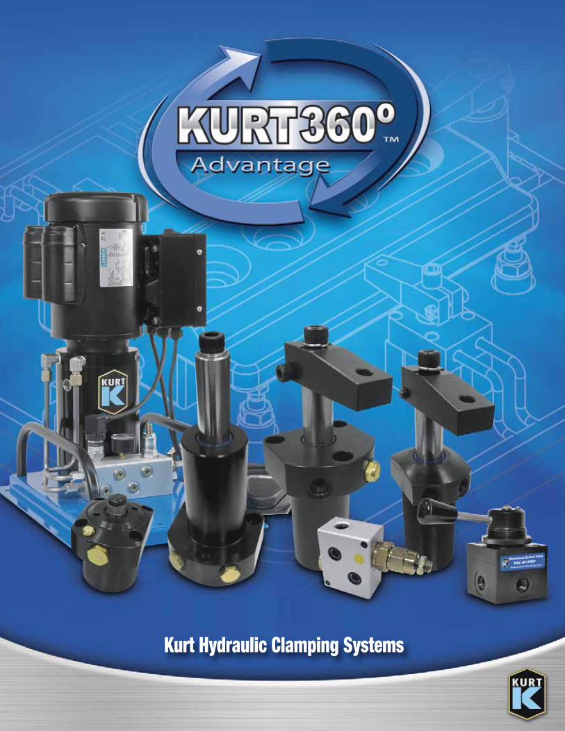
Kurt Hydraulic Clamping Systems
2
Advantage™
Swing Clamp Cylinder . . . . . . . . . . . . . . . . . . . . 2Swing Clamps - Introduction . . . . . . . . . . . . . . . 3Series 030 Swing Clamps . . . . . . . . . . . . . . . 4-5Series 040 Swing Clamps and Jam Nuts . . . . 6-7Series 050 Swing Clamps . . . . . . . . . . . . . . . 8-9VT Series Link Clamp . . . . . . . . . . . . . . . . . . . 10TC Clamping Cylinder . . . . . . . . . . . . . . . . . . . 11WS-BL Work Support . . . . . . . . . . . . . . . . . 12-13VSQ Series Valves . . . . . . . . . . . . . . . . . . . . . . 13PRV Series Valves . . . . . . . . . . . . . . . . . . . . . . 14FCV Series Valves . . . . . . . . . . . . . . . . . . . . . . 14KDC Series Directional Control Valves . . . . . . . 15HAWE Valves . . . . . . . . . . . . . . . . . . . . . . . . . . 16Swing Clamp Arms . . . . . . . . . . . . . . . . . . . . . 17KHP5000 Hydraulic Pump . . . . . . . . . . . . . . . . 18Hydraulic Intensifier . . . . . . . . . . . . . . . . . . . . 18Seal Kits . . . . . . . . . . . . . . . . . . . . . . . . . . . . . 19
Benefit from Our WideRange of Options.The KURT 360° ADVANTAGE represents our
complete precision manufacturing product
offering. Gain powerful manufacturing
advantages from a wide range of Hydraulic
Clamps & Pumps.
Index
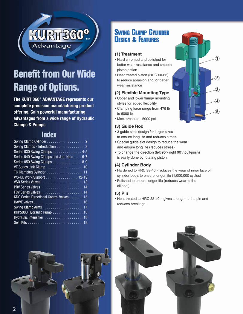
SWING CLAMP CYLINDERDESIGN & FEATURES
(1) Treatment
• Hard chromed and polished forbetter wear resistance and smooth piston action
• Heat treated piston (HRC 60-63)to reduce abrasion and for betterwear resistance
(2) Flexible Mounting Type
• Upper and lower flange mountingstyles for added flexibility
• Clamping force range from 475 lb to 6000 lb
• Max. pressure : 5000 psi
(3) Guide Rod
• 3 guide slots design for larger sizes to ensure long life and reduces stress.
• Special guide slot design to reduce the wear and ensure long life (reduces stress)
• To change the direction (left 90°/ right 90°/ pull∙push) is easily done by rotating piston.
(4) Cylinder Body
• Hardened to HRC 38-46 - reduces the wear of inner face ofcylinder body, to ensure longer life (1,000,000 cycles)
• Polished to ensure longer life (reduces wear to the oil seal)
(5) Pin
• Heat treated to HRC 38-40 – gives strength to the pin andreduces breakage.
1
2
3
4
5
3
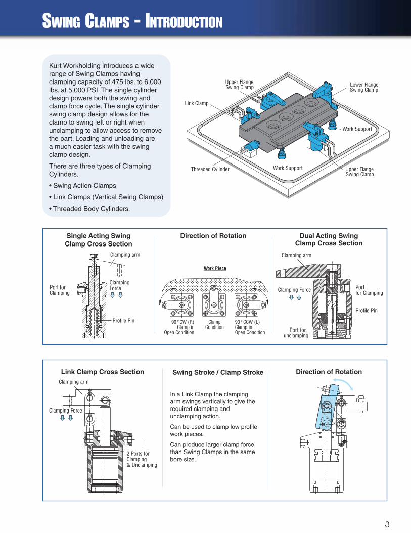
Clamping arm
Profile Pin
Port forunclamping
Portfor ClampingClamping Force
90 CW (R)Clamp in
Open Condition
° 90 CCW (L)Clamp inOpen Condition
°ClampCondition
Work Piece
Clamping arm
2 Ports forClamping& Unclamping
Clamping Force
SWING CLAMPS - INTRODUCTION
Dual Acting Swing Clamp Cross Section
Direction of Rotation
Link Clamp Cross Section Swing Stroke / Clamp Stroke Direction of Rotation
Lower FlangeSwing Clamp
Work SupportThreaded Cylinder
Link Clamp
Upper FlangeSwing Clamp
Upper FlangeSwing Clamp
Work Support
Kurt Workholding introduces a widerange of Swing Clamps havingclamping capacity of 475 lbs. to 6,000lbs. at 5,000 PSI. The single cylinderdesign powers both the swing andclamp force cycle. The single cylinderswing clamp design allows for theclamp to swing left or right whenunclamping to allow access to removethe part. Loading and unloading are a much easier task with the swingclamp design.
There are three types of ClampingCylinders.
• Swing Action Clamps
• Link Clamps (Vertical Swing Clamps)
• Threaded Body Cylinders.
In a Link Clamp the clampingarm swings vertically to give therequired clamping andunclamping action.
Can be used to clamp low profilework pieces.
Can produce larger clamp forcethan Swing Clamps in the samebore size.
Single Acting Swing
Clamp Cross Section
Clamping arm
Profile Pin
Port forClamping
ClampingForce
4 www.kurtworkholding.com | Toll Free Phone 1-877-226-7823 | Toll Free Fax 1-877-226-7828 | Phone 763-574-8309 | Fax 763-574-8313
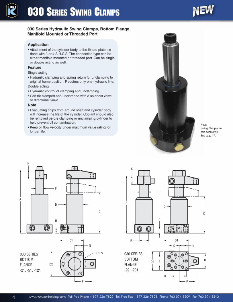
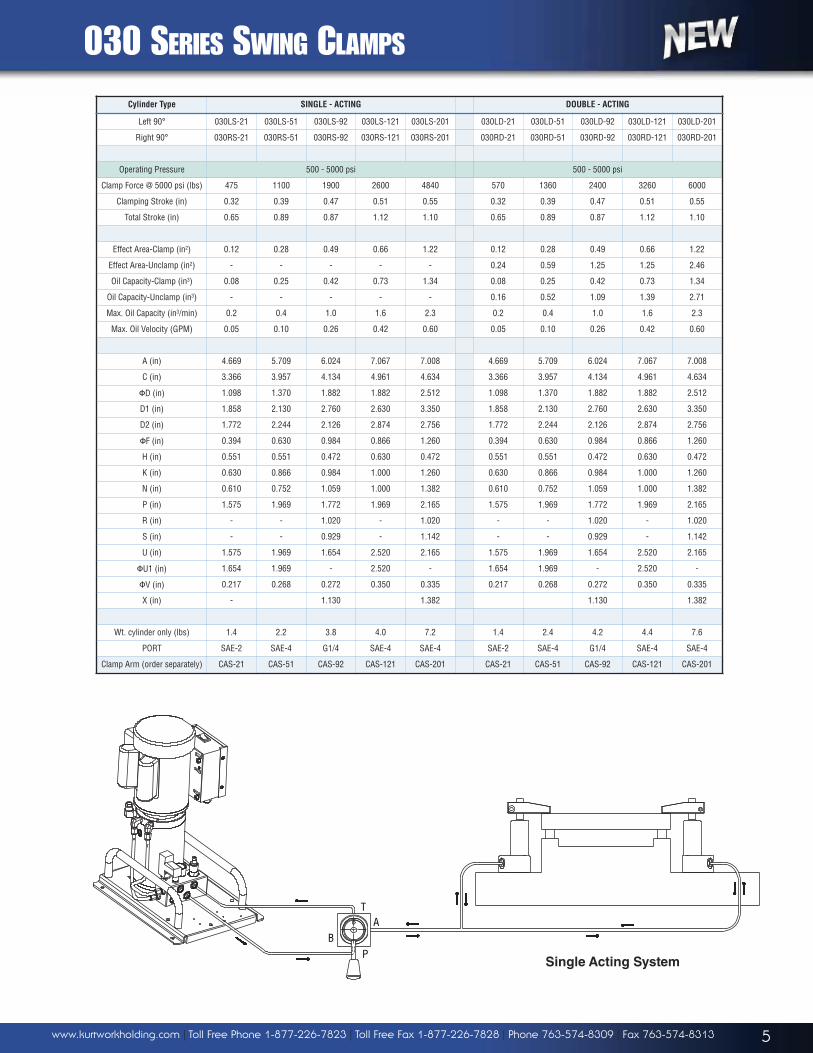
030 SERIES SWING CLAMPS
H
U
D
F
U1, V
X
U
R
D2 S
P
N
D1
H
C
A
K
F
D
P
N
D1
D2
C
K
A
030 SERIESBOTTOM FLANGE-92, -201
030 SERIESBOTTOM FLANGE-21, -51, -121
030 Series Hydraulic Swing Clamps, Bottom Flange
Manifold Mounted or Threaded Port
Application
• Attachment of the cylinder body to the fixture platen isdone with 3 or 4 S.H.C.S. The connection type can beeither manifold mounted or threaded port. Can be singleor double acting as well.
Feature
Single acting• Hydraulic clamping and spring return for unclamping to
original home position. Requires only one hydraulic line.Double acting• Hydraulic control of clamping and unclamping.• Can be clamped and unclamped with a solenoid valve
or directional valve.
Note
• Evacuating chips from around shaft and cylinder bodywill increase the life of the cylinder. Coolant should alsobe removed before clamping or unclamping cylinder tohelp prevent oil contamination.
• Keep oil flow velocity under maximum value rating forlonger life.
Note: Swing Clamp armssold separately. See page 17.
5www.kurtworkholding.com | Toll Free Phone 1-877-226-7823 | Toll Free Fax 1-877-226-7828 | Phone 763-574-8309 | Fax 763-574-8313
030 SERIES SWING CLAMPS
Cylinder Type SINGLE - ACTING DOUBLE - ACTING
Left 90° 030LS-21 030LS-51 030LS-92 030LS-121 030LS-201 030LD-21 030LD-51 030LD-92 030LD-121 030LD-201
Right 90° 030RS-21 030RS-51 030RS-92 030RS-121 030RS-201 030RD-21 030RD-51 030RD-92 030RD-121 030RD-201
Operating Pressure 500 - 5000 psi 500 - 5000 psi
Clamp Force @ 5000 psi (lbs) 475 1100 1900 2600 4840 570 1360 2400 3260 6000
Clamping Stroke (in) 0.32 0.39 0.47 0.51 0.55 0.32 0.39 0.47 0.51 0.55
Total Stroke (in) 0.65 0.89 0.87 1.12 1.10 0.65 0.89 0.87 1.12 1.10
Effect Area-Clamp (in2) 0.12 0.28 0.49 0.66 1.22 0.12 0.28 0.49 0.66 1.22
Effect Area-Unclamp (in2) - - - - - 0.24 0.59 1.25 1.25 2.46
Oil Capacity-Clamp (in3) 0.08 0.25 0.42 0.73 1.34 0.08 0.25 0.42 0.73 1.34
Oil Capacity-Unclamp (in3) - - - - - 0.16 0.52 1.09 1.39 2.71
Max. Oil Capacity (in3/min) 0.2 0.4 1.0 1.6 2.3 0.2 0.4 1.0 1.6 2.3
Max. Oil Velocity (GPM) 0.05 0.10 0.26 0.42 0.60 0.05 0.10 0.26 0.42 0.60
A (in) 4.669 5.709 6.024 7.067 7.008 4.669 5.709 6.024 7.067 7.008
C (in) 3.366 3.957 4.134 4.961 4.634 3.366 3.957 4.134 4.961 4.634
�D (in) 1.098 1.370 1.882 1.882 2.512 1.098 1.370 1.882 1.882 2.512
D1 (in) 1.858 2.130 2.760 2.630 3.350 1.858 2.130 2.760 2.630 3.350
D2 (in) 1.772 2.244 2.126 2.874 2.756 1.772 2.244 2.126 2.874 2.756
�F (in) 0.394 0.630 0.984 0.866 1.260 0.394 0.630 0.984 0.866 1.260
H (in) 0.551 0.551 0.472 0.630 0.472 0.551 0.551 0.472 0.630 0.472
K (in) 0.630 0.866 0.984 1.000 1.260 0.630 0.866 0.984 1.000 1.260
N (in) 0.610 0.752 1.059 1.000 1.382 0.610 0.752 1.059 1.000 1.382
P (in) 1.575 1.969 1.772 1.969 2.165 1.575 1.969 1.772 1.969 2.165
R (in) - - 1.020 - 1.020 - - 1.020 - 1.020
S (in) - - 0.929 - 1.142 - - 0.929 - 1.142
U (in) 1.575 1.969 1.654 2.520 2.165 1.575 1.969 1.654 2.520 2.165
�U1 (in) 1.654 1.969 - 2.520 - 1.654 1.969 - 2.520 -
�V (in) 0.217 0.268 0.272 0.350 0.335 0.217 0.268 0.272 0.350 0.335
X (in) - 1.130 1.382 1.130 1.382
Wt. cylinder only (lbs) 1.4 2.2 3.8 4.0 7.2 1.4 2.4 4.2 4.4 7.6
PORT SAE-2 SAE-4 G1/4 SAE-4 SAE-4 SAE-2 SAE-4 G1/4 SAE-4 SAE-4
Clamp Arm (order separately) CAS-21 CAS-51 CAS-92 CAS-121 CAS-201 CAS-21 CAS-51 CAS-92 CAS-121 CAS-201
T
BP
A
Single Acting System
6 www.kurtworkholding.com | Toll Free Phone 1-877-226-7823 | Toll Free Fax 1-877-226-7828 | Phone 763-574-8309 | Fax 763-574-8313
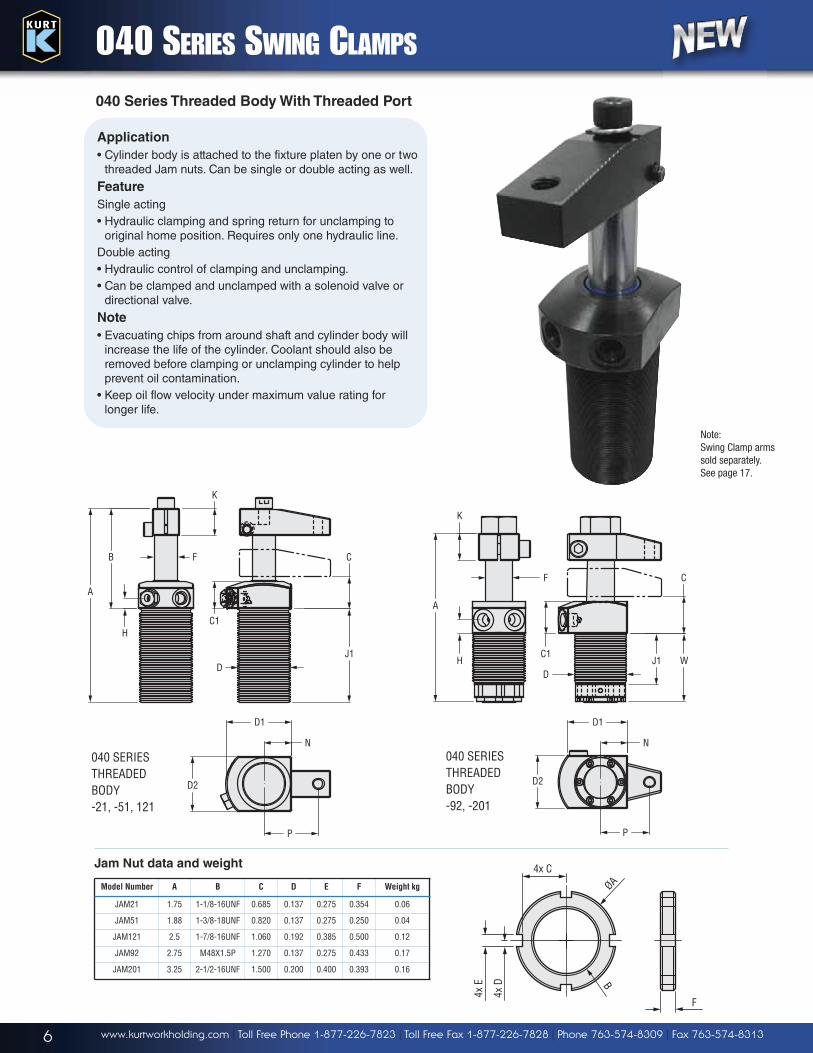
D
F
H
J1
C1
C
K
B
AA
K
C1WJ1
C
H
F
D
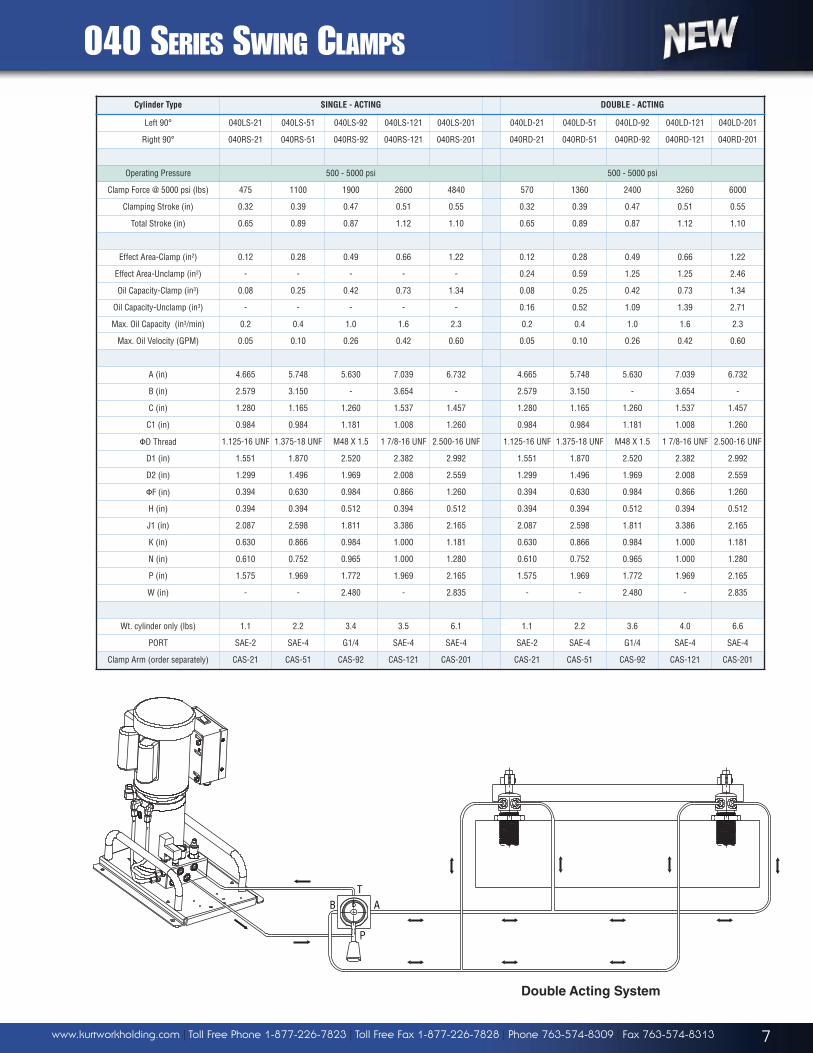
040 SERIES SWING CLAMPS
Application
• Cylinder body is attached to the fixture platen by one or twothreaded Jam nuts. Can be single or double acting as well.
Feature
Single acting• Hydraulic clamping and spring return for unclamping to
original home position. Requires only one hydraulic line.Double acting• Hydraulic control of clamping and unclamping.• Can be clamped and unclamped with a solenoid valve or
directional valve.
Note
• Evacuating chips from around shaft and cylinder body willincrease the life of the cylinder. Coolant should also beremoved before clamping or unclamping cylinder to helpprevent oil contamination.
• Keep oil flow velocity under maximum value rating forlonger life.
040 Series Threaded Body With Threaded Port
Note: Swing Clamp armssold separately. See page 17.
Jam Nut data and weight
Model Number A B C D E F Weight kg
JAM21 1.75 1-1/8-16UNF 0.685 0.137 0.275 0.354 0.06
JAM51 1.88 1-3/8-18UNF 0.820 0.137 0.275 0.250 0.04
JAM121 2.5 1-7/8-16UNF 1.060 0.192 0.385 0.500 0.12
JAM92 2.75 M48X1.5P 1.270 0.137 0.275 0.433 0.17
JAM201 3.25 2-1/2-16UNF 1.500 0.200 0.400 0.393 0.16
ØA
B
4x C
4x D
4x E
F
N
D1
D2
040 SERIESTHREADED BODY-92, -201
D2
D1
N
PP
040 SERIESTHREADED BODY-21, -51, 121
7www.kurtworkholding.com | Toll Free Phone 1-877-226-7823 | Toll Free Fax 1-877-226-7828 | Phone 763-574-8309 | Fax 763-574-8313
Cylinder Type SINGLE - ACTING DOUBLE - ACTING
Left 90° 040LS-21 040LS-51 040LS-92 040LS-121 040LS-201 040LD-21 040LD-51 040LD-92 040LD-121 040LD-201
Right 90° 040RS-21 040RS-51 040RS-92 040RS-121 040RS-201 040RD-21 040RD-51 040RD-92 040RD-121 040RD-201
Operating Pressure 500 - 5000 psi 500 - 5000 psi
Clamp Force @ 5000 psi (lbs) 475 1100 1900 2600 4840 570 1360 2400 3260 6000
Clamping Stroke (in) 0.32 0.39 0.47 0.51 0.55 0.32 0.39 0.47 0.51 0.55
Total Stroke (in) 0.65 0.89 0.87 1.12 1.10 0.65 0.89 0.87 1.12 1.10
Effect Area-Clamp (in2) 0.12 0.28 0.49 0.66 1.22 0.12 0.28 0.49 0.66 1.22
Effect Area-Unclamp (in2) - - - - - 0.24 0.59 1.25 1.25 2.46
Oil Capacity-Clamp (in3) 0.08 0.25 0.42 0.73 1.34 0.08 0.25 0.42 0.73 1.34
Oil Capacity-Unclamp (in3) - - - - - 0.16 0.52 1.09 1.39 2.71
Max. Oil Capacity (in3/min) 0.2 0.4 1.0 1.6 2.3 0.2 0.4 1.0 1.6 2.3
Max. Oil Velocity (GPM) 0.05 0.10 0.26 0.42 0.60 0.05 0.10 0.26 0.42 0.60
A (in) 4.665 5.748 5.630 7.039 6.732 4.665 5.748 5.630 7.039 6.732
B (in) 2.579 3.150 - 3.654 - 2.579 3.150 - 3.654 -
C (in) 1.280 1.165 1.260 1.537 1.457 1.280 1.165 1.260 1.537 1.457
C1 (in) 0.984 0.984 1.181 1.008 1.260 0.984 0.984 1.181 1.008 1.260
�D Thread 1.125-16 UNF 1.375-18 UNF M48 X 1.5 1 7/8-16 UNF 2.500-16 UNF 1.125-16 UNF 1.375-18 UNF M48 X 1.5 1 7/8-16 UNF 2.500-16 UNF
D1 (in) 1.551 1.870 2.520 2.382 2.992 1.551 1.870 2.520 2.382 2.992
D2 (in) 1.299 1.496 1.969 2.008 2.559 1.299 1.496 1.969 2.008 2.559
�F (in) 0.394 0.630 0.984 0.866 1.260 0.394 0.630 0.984 0.866 1.260
H (in) 0.394 0.394 0.512 0.394 0.512 0.394 0.394 0.512 0.394 0.512
J1 (in) 2.087 2.598 1.811 3.386 2.165 2.087 2.598 1.811 3.386 2.165
K (in) 0.630 0.866 0.984 1.000 1.181 0.630 0.866 0.984 1.000 1.181
N (in) 0.610 0.752 0.965 1.000 1.280 0.610 0.752 0.965 1.000 1.280
P (in) 1.575 1.969 1.772 1.969 2.165 1.575 1.969 1.772 1.969 2.165
W (in) - - 2.480 - 2.835 - - 2.480 - 2.835
Wt. cylinder only (lbs) 1.1 2.2 3.4 3.5 6.1 1.1 2.2 3.6 4.0 6.6
PORT SAE-2 SAE-4 G1/4 SAE-4 SAE-4 SAE-2 SAE-4 G1/4 SAE-4 SAE-4
Clamp Arm (order separately) CAS-21 CAS-51 CAS-92 CAS-121 CAS-201 CAS-21 CAS-51 CAS-92 CAS-121 CAS-201
040 SERIES SWING CLAMPS
TB
P
A
Double Acting System
8 www.kurtworkholding.com | Toll Free Phone 1-877-226-7823 | Toll Free Fax 1-877-226-7828 | Phone 763-574-8309 | Fax 763-574-8313
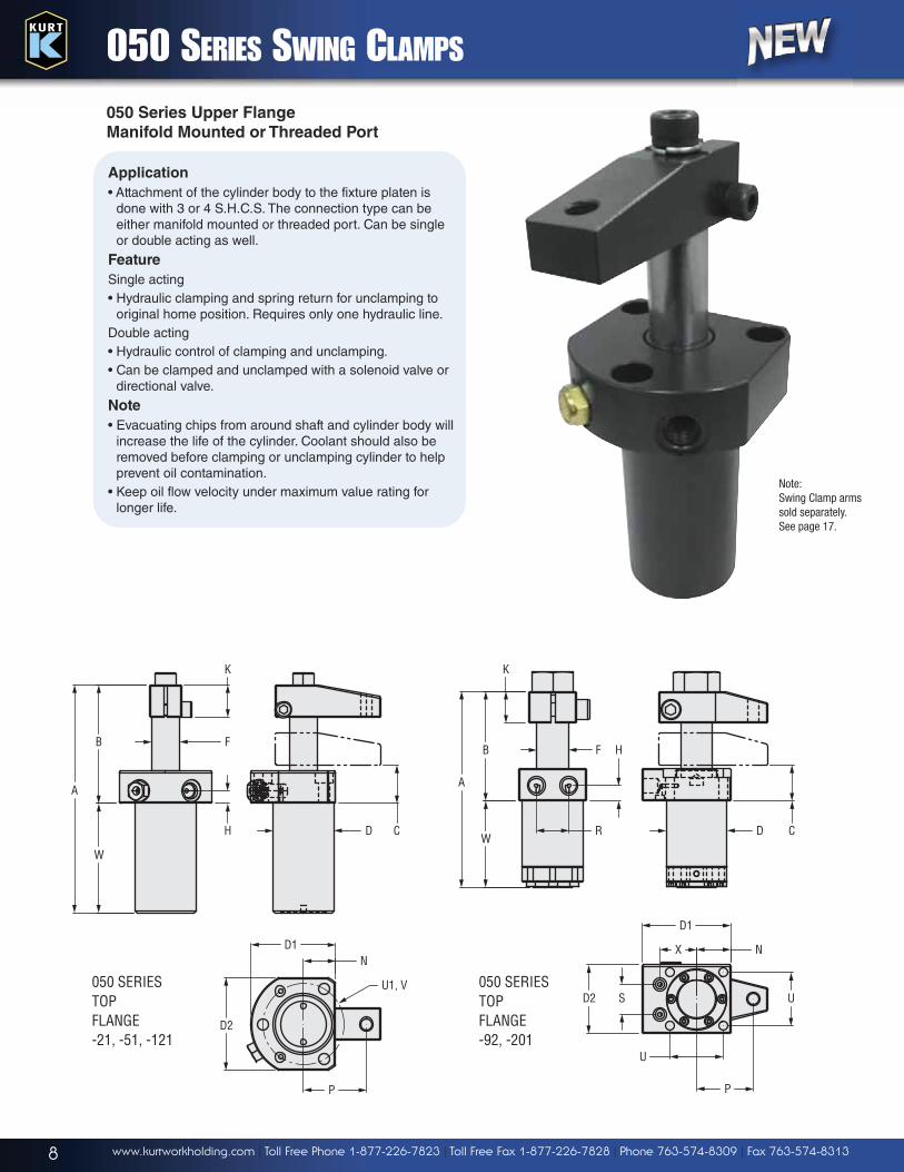
050 SERIES SWING CLAMPS
P
050 SERIESTOP FLANGE-92, -201
050 SERIESTOP FLANGE-21, -51, -121
A
B
W
CD
F
H
D1N
P
U1, V
D2
A
K
B
WC
F
D
D1
N
U
D2 US
R
X
H
K
Application
• Attachment of the cylinder body to the fixture platen isdone with 3 or 4 S.H.C.S. The connection type can beeither manifold mounted or threaded port. Can be singleor double acting as well.
Feature
Single acting• Hydraulic clamping and spring return for unclamping to
original home position. Requires only one hydraulic line.Double acting• Hydraulic control of clamping and unclamping.• Can be clamped and unclamped with a solenoid valve or
directional valve.
Note
• Evacuating chips from around shaft and cylinder body willincrease the life of the cylinder. Coolant should also beremoved before clamping or unclamping cylinder to helpprevent oil contamination.
• Keep oil flow velocity under maximum value rating forlonger life.
050 Series Upper Flange
Manifold Mounted or Threaded Port
Note: Swing Clamp armssold separately. See page 17.
9www.kurtworkholding.com | Toll Free Phone 1-877-226-7823 | Toll Free Fax 1-877-226-7828 | Phone 763-574-8309 | Fax 763-574-8313
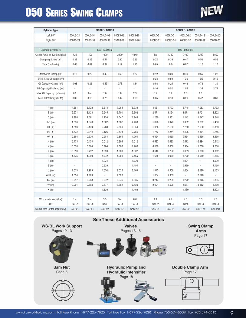
050 SERIES SWING CLAMPS
Cylinder Type SINGLE - ACTING DOUBLE - ACTING
Left 90° 050LS-21 050LS-51 050LS-92 050LS-121 050LS-201 050LD-21 050LD-51 050LD-92 050LD-121 050LD-201
Right 90° 050RS-21 050RS-51 050RS-92 050RS-121 050RS-201 050RD-21 050RD-51 050RD-92 050RD-121 050RD-201
Operating Pressure 500 - 5000 psi 500 - 5000 psi
Clamp Force @ 5000 psi (lbs) 475 1100 1900 2600 4840 570 1360 2400 3260 6000
Clamping Stroke (in) 0.32 0.39 0.47 0.50 0.55 0.32 0.39 0.47 0.50 0.55
Total Stroke (in) 0.65 0.89 0.87 1.12 1.10 0.65 .8i9 0.87 1.12 1.10
Effect Area-Clamp (in2) 0.12 0.28 0.49 0.66 1.22 0.12 0.28 0.49 0.66 1.22
Effect Area-Unclamp (in2) - - - - - 0.24 0.59 1.25 1.25 2.46
Oil Capacity-Clamp (in3) 0.08 0.25 0.42 0.73 1.34 0.08 0.25 0.42 0.73 1.34
Oil Capacity-Unclamp (in3) - - - - - 0.16 0.52 1.09 1.39 2.71
Max. Oil Capacity (in3/min) 0.2 0.4 1.0 1.6 2.3 0.2 0.4 1.0 1.6 .
Max. Oil Velocity (GPM) 0.05 0.10 0.26 0.42 0.60 0.05 0.10 0.26 0.42 0.60
A (in) 4.661 5.722 5.618 7.083 6.732 4.661 5.722 5.748 7.083 6.732
B (in) 2.571 3.124 2.945 3.701 3.602 2.571 3.124 3.071 3.701 3.602
C (in) 1.280 1.561 1.134 1.547 1.248 1.280 1.561 1.142 1.547 1.248
�D (in) 1.098 1.370 1.882 1.882 2.480 1.098 1.370 1.882 1.882 2.480
D1 (in) 1.858 2.130 2.760 2.630 3.350 1.858 2.130 2.760 2.630 3.350
D2 (in) 1.772 2.244 2.126 2.874 2.756 1.772 2.244 2.126 2.874 2.756
�F (in) 0.394 0.630 0.984 0.866 1.260 0.394 0.630 0.984 0.866 1.260
H (in) 0.433 0.433 0.512 0.394 0.512 0.433 0.433 0.512 0.394 0.512
K (in) 0.630 0.866 0.984 1.000 1.260 0.630 0.866 0.984 1.000 1.260
N (in) 0.610 0.752 1.059 1.000 1.382 0.610 0.752 1.059 1.000 1.382
P (in) 1.575 1.969 1.772 1.969 2.165 1.575 1.969 1.772 1.969 2.165
R (in) - - 1.024 - 1.020 - - 1.024 - 1.020
S (in) - - 0.929 - 1.150 - - 0.929 - 1.150
U (in) 1.575 1.969 1.654 2.520 2.165 1.575 1.969 1.654 2.520 2.165
�U1 (in) 1.654 1.969 - 2.520 - 1.654 1.969 - 2.520 -
�V (in) 0.217 0.268 0.272 0.346 0.335 0.217 0.268 0.272 0.346 0.335
W (in) 2.091 2.598 2.677 3.382 3.130 2.091 2.598 2.677 3.382 3.130
X (in) - - 1.130 - 1.402 - - 1.130 - 1.402
Wt. cylinder only (lbs) 1.4 2.4 3.3 3.4 6.6 1.4 2.4 4.0 3.5 7.0
PORT SAE-2 SAE-4 G1/4 SAE-4 SAE-4 SAE-2 SAE-4 G1/4 SAE-4 SAE-4
Clamp Arm (order separately) CAS-21 CAS-51 CAS-92 CAS-121 CAS-201 CAS-21 CAS-51 CAS-92 CAS-121 CAS-201
See These Additional Accessories
WS-BL Work Support
Pages 12-13Valves
Pages 13-16Swing Clamp
Arms
Page 17
Jam Nut
Page 6Hydraulic Pump and
Hydraulic Intensifier
Page 18
Double Clamp Arm
Page 17
10 www.kurtworkholding.com | Toll Free Phone 1-877-226-7823 | Toll Free Fax 1-877-226-7828 | Phone 763-574-8309 | Fax 763-574-8313
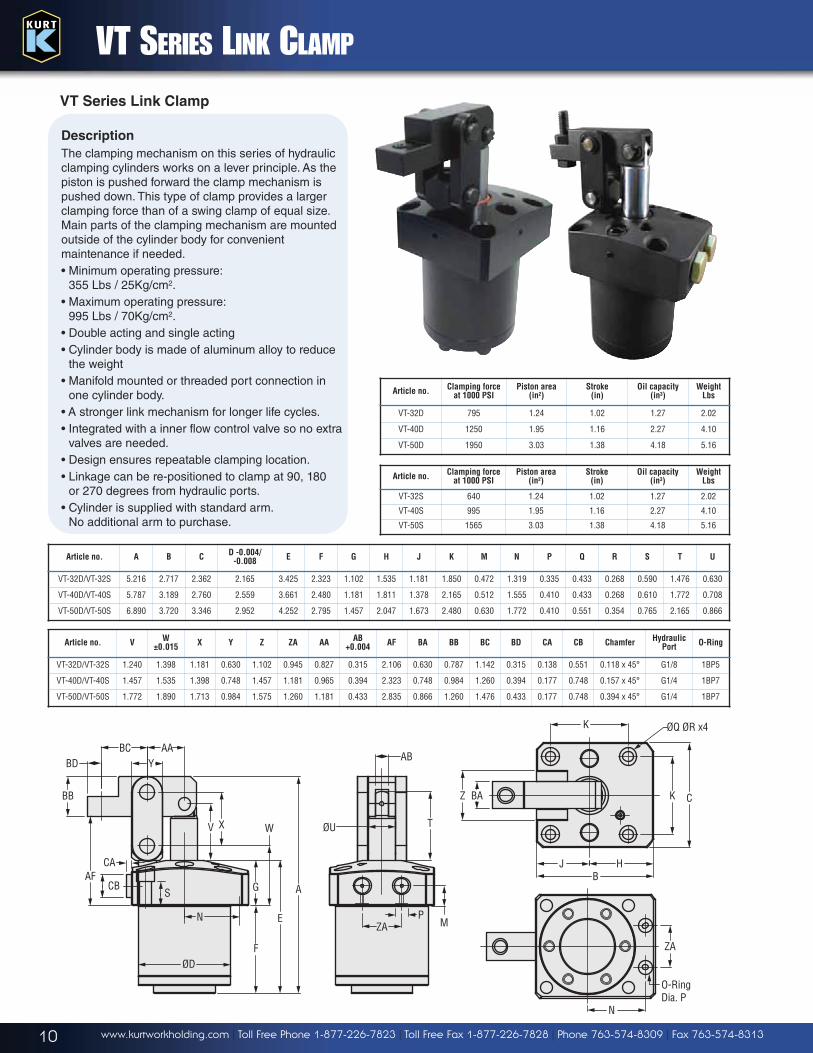
Article no. A B CD -0.004/
-0.008E F G H J K M N P Q R S T U
VT-32D/VT-32S 5.216 2.717 2.362 2.165 3.425 2.323 1.102 1.535 1.181 1.850 0.472 1.319 0.335 0.433 0.268 0.590 1.476 0.630
VT-40D/VT-40S 5.787 3.189 2.760 2.559 3.661 2.480 1.181 1.811 1.378 2.165 0.512 1.555 0.410 0.433 0.268 0.610 1.772 0.708
VT-50D/VT-50S 6.890 3.720 3.346 2.952 4.252 2.795 1.457 2.047 1.673 2.480 0.630 1.772 0.410 0.551 0.354 0.765 2.165 0.866
Article no. VW
±0.015X Y Z ZA AA
AB +0.004
AF BA BB BC BD CA CB ChamferHydraulic
PortO-Ring
VT-32D/VT-32S 1.240 1.398 1.181 0.630 1.102 0.945 0.827 0.315 2.106 0.630 0.787 1.142 0.315 0.138 0.551 0.118 x 45° G1/8 1BP5
VT-40D/VT-40S 1.457 1.535 1.398 0.748 1.457 1.181 0.965 0.394 2.323 0.748 0.984 1.260 0.394 0.177 0.748 0.157 x 45° G1/4 1BP7
VT-50D/VT-50S 1.772 1.890 1.713 0.984 1.575 1.260 1.181 0.433 2.835 0.866 1.260 1.476 0.433 0.177 0.748 0.394 x 45° G1/4 1BP7
Article no.Clamping force
at 1000 PSIPiston area
(in2)Stroke
(in)Oil capacity
(in3)Weight
Lbs
VT-32D 795 1.24 1.02 1.27 2.02
VT-40D 1250 1.95 1.16 2.27 4.10
VT-50D 1950 3.03 1.38 4.18 5.16
Article no.Clamping force
at 1000 PSIPiston area
(in2)Stroke
(in)Oil capacity
(in3)Weight
Lbs
VT-32S 640 1.24 1.02 1.27 2.02
VT-40S 995 1.95 1.16 2.27 4.10
VT-50S 1565 3.03 1.38 4.18 5.16
VT SERIES LINK CLAMP
Z BA
JB
H
K C
ØQ ØR x4K
BDBC AA
Y
BB
AF
S
V WX
N
ØD
G
F
E
A
ZA M
T
AB
ØU
CB
CA
P
VT Series Link Clamp
Description
The clamping mechanism on this series of hydraulicclamping cylinders works on a lever principle. As thepiston is pushed forward the clamp mechanism ispushed down. This type of clamp provides a largerclamping force than of a swing clamp of equal size.Main parts of the clamping mechanism are mountedoutside of the cylinder body for convenientmaintenance if needed.• Minimum operating pressure:
355 Lbs / 25Kg/cm2.• Maximum operating pressure:
995 Lbs / 70Kg/cm2.• Double acting and single acting• Cylinder body is made of aluminum alloy to reduce
the weight• Manifold mounted or threaded port connection in
one cylinder body.• A stronger link mechanism for longer life cycles.• Integrated with a inner flow control valve so no extra
valves are needed.• Design ensures repeatable clamping location.• Linkage can be re-positioned to clamp at 90, 180
or 270 degrees from hydraulic ports.• Cylinder is supplied with standard arm.
No additional arm to purchase.
N
O-RingDia. P
ZA
11www.kurtworkholding.com | Toll Free Phone 1-877-226-7823 | Toll Free Fax 1-877-226-7828 | Phone 763-574-8309 | Fax 763-574-8313
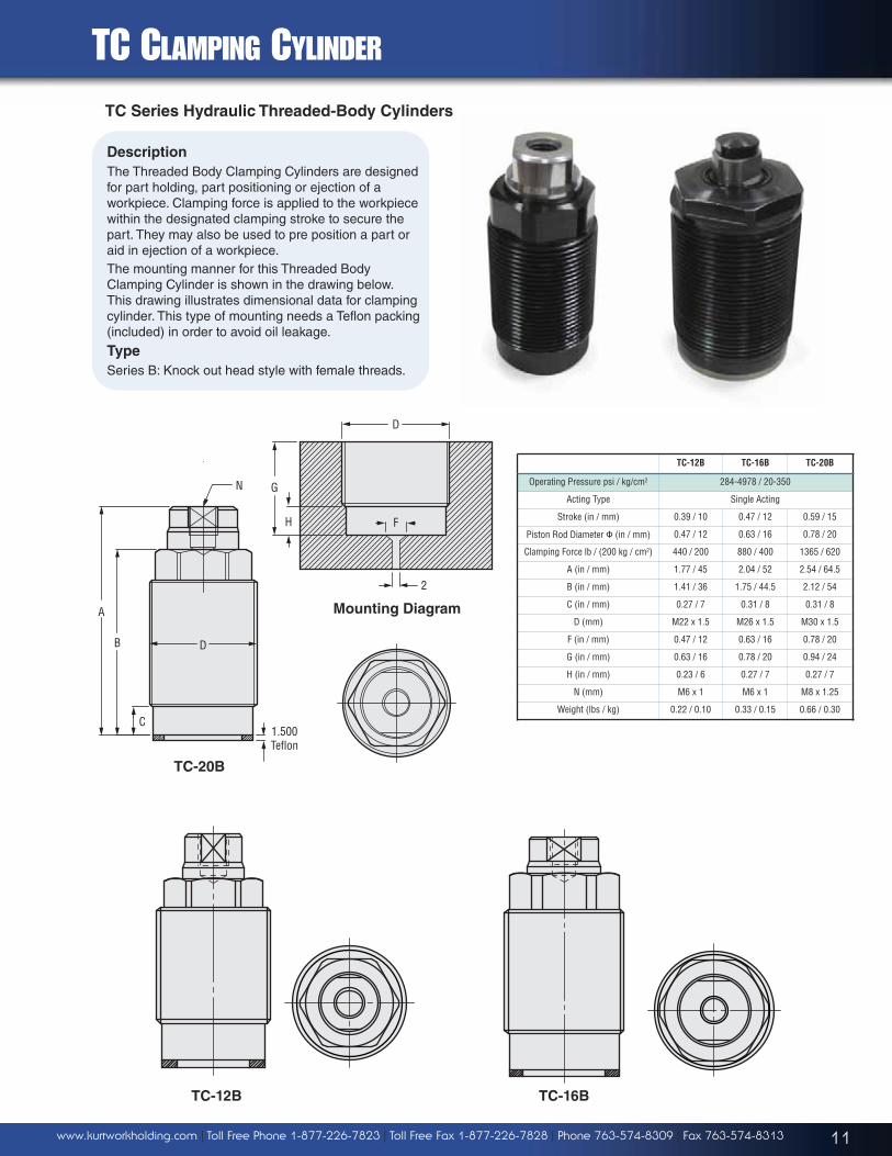
TC CLAMPING CYLINDER
TC-12B TC-16B TC-20B
Operating Pressure psi / kg/cm2 284-4978 / 20-350
Acting Type Single Acting
Stroke (in / mm) 0.39 / 10 0.47 / 12 0.59 / 15
Piston Rod Diameter � (in / mm) 0.47 / 12 0.63 / 16 0.78 / 20
Clamping Force lb / (200 kg / cm2) 440 / 200 880 / 400 1365 / 620
A (in / mm) 1.77 / 45 2.04 / 52 2.54 / 64.5
B (in / mm) 1.41 / 36 1.75 / 44.5 2.12 / 54
C (in / mm) 0.27 / 7 0.31 / 8 0.31 / 8
D (mm) M22 x 1.5 M26 x 1.5 M30 x 1.5
F (in / mm) 0.47 / 12 0.63 / 16 0.78 / 20
G (in / mm) 0.63 / 16 0.78 / 20 0.94 / 24
H (in / mm) 0.23 / 6 0.27 / 7 0.27 / 7
N (mm) M6 x 1 M6 x 1 M8 x 1.25
Weight (lbs / kg) 0.22 / 0.10 0.33 / 0.15 0.66 / 0.30
TC-12B TC-16B
N
DB
A
C1.500Teflon
TC-20B
TC Series Hydraulic Threaded-Body Cylinders
Description
The Threaded Body Clamping Cylinders are designedfor part holding, part positioning or ejection of aworkpiece. Clamping force is applied to the workpiecewithin the designated clamping stroke to secure thepart. They may also be used to pre position a part oraid in ejection of a workpiece. The mounting manner for this Threaded BodyClamping Cylinder is shown in the drawing below.This drawing illustrates dimensional data for clampingcylinder. This type of mounting needs a Teflon packing(included) in order to avoid oil leakage.
Type
Series B: Knock out head style with female threads.
D
G
H F
2
Mounting Diagram
12 www.kurtworkholding.com | Toll Free Phone 1-877-226-7823 | Toll Free Fax 1-877-226-7828 | Phone 763-574-8309 | Fax 763-574-8313
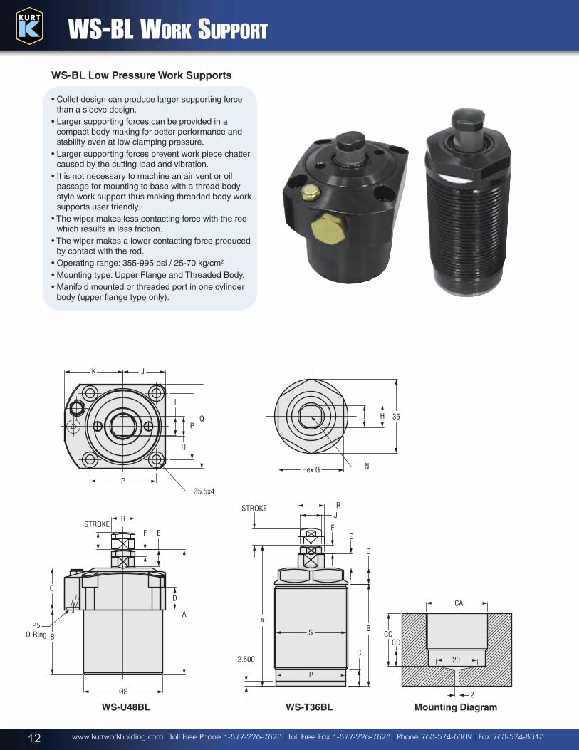
WS-BL WORK SUPPORT
RJ
FE
D
S B
C
P
2.500
A
STROKE
Mounting Diagram
R
F ESTROKE
A
DC
BP5
O-Ring
ØS
WS-U48BL
CA
20
CCCD
2
WS-BL Low Pressure Work Supports
• Collet design can produce larger supporting forcethan a sleeve design.
• Larger supporting forces can be provided in acompact body making for better performance andstability even at low clamping pressure.
• Larger supporting forces prevent work piece chattercaused by the cutting load and vibration.
• It is not necessary to machine an air vent or oilpassage for mounting to base with a thread bodystyle work support thus making threaded body worksupports user friendly.
• The wiper makes less contacting force with the rodwhich results in less friction.
• The wiper makes a lower contacting force producedby contact with the rod.
• Operating range: 355-995 psi / 25-70 kg/cm2
• Mounting type: Upper Flange and Threaded Body.• Manifold mounted or threaded port in one cylinder
body (upper flange type only).
Hex G
36HI
N
K J
P
PQ
H
I
Ø5.5x4
WS-T36BL
13www.kurtworkholding.com | Toll Free Phone 1-877-226-7823 | Toll Free Fax 1-877-226-7828 | Phone 763-574-8309 | Fax 763-574-8313
55 60
2020
15.5
V1
5
V1
Ø7.7x2
Ø5.5x2
3015
3015
Ø13x1.4±.05
43.5
C1
48
43 18
16 15.5
48
43.55
5
43
5.8550
34
C1
Ø5.5x2
WS-BL WORK SUPPORT • VSQ SERIES
WS-T26BL WS-T30BL WS-T36BL WS-U40BL WS-U48BL
Supporting Force (Lbs /(70kg/cm2) kg) 460 Lbs / 210 kg 660 Lbs / 300 kg 770 Lbs / 350 kg 840 Lbs / 380 kg 1,100 Lbs / 500 kg
Plunger Stroke (in / mm) 0.25 / 6.5 0.31 / 8 0.31 / 8 0.315 / 8 0.394 / 10
Max Operating Pressure (psi / kg/cm2) 1,500 psi / 105kg/cm2
Normal Pressure (psi / kg/cm2) 355-995 psi / 25-70kg/cm2
A (in / mm) 2.60 / 66 2.87 / 73 2.71 / 69 2.63 / 67 2.95 / 75
B (in / mm) 1.83 / 46.5 2.04 / 51.8 1.917 / 48.7 1.22 / 31 1.53 / 39
C (in / mm) 0.256 / 6.5 0.37 / 9.5 0.33 / 8.4 0.98 / 25 0.98 / 25
D (in / mm) 0.41 / 10.5 0.40 / 10.2 0.366 / 9.3 0.57 / 14.5 0.53 / 13.5
E (in / mm) 0.19 / 5 0.27 / 7 0.27 / 7 0.39 / 10 0.39 / 10
F (in / mm) 0.16 / 4 0.16 / 4 0.16 / 4 0.16 / 4 0.16 / 4
G (in / mm) 0.94 / 24 1.06 / 27 1.26 / 32 - -
H (in / mm) 0.35 / 9 0.31 / 8 0.43 / 11 0.43 / 11 0.47 / 12
I (in / mm) 0.35 / 9 0.35 / 9 0.41 / 10.5 0.43 / 11 0.43 / 11
J (in / mm) - - - 0.88 / 22.5 1.00 / 25.5
K (in / mm) - - - 1.24 / 31.5 1.24 / 31.5
N (in / mm) M6 x 12D M6 x 12D M8 x 11D M10 x 11D M10 x 11D
P � (in / mm) 0.94 / 24 1.11 / 28.2 1.34 / 34.2 1.34 / 34 1.57 / 40
Q � (in / mm) 1.02 / 26 1.18 / 30 1.42 / 36 1.77 / 45 2.00 / 51
R � (in / mm) 0.39 / 10 0.39 / 10 0.51 / 13 0.51 / 13 0.55 / 14
S M26 x 1.5 M30 x 1.5 M36 x 1.5 �1.57 / 40 �1.89 / 48
CA M26 x 1.5 M30 x 1.5 M36 x 1.5 - -
CB (in / mm) 0.95 / 24.3 1.12 / 28.5 1.36 / 34.5 - -
CC (in / mm) 0.78~1.18 / 20~30 0.78~1.97 / 20~50 0.78~1.89 / 20~48 - -
CD (in / mm) 0.07 / 2 0.35 / 9 0.31 / 8 - -
Weight (lbs / kg) 0.44 / 0.20 0.55 / 0.25 0.77 / 0.35 1.32 / 0.6 1.76 / 0.8
Max Pressure Bar / PSI
Adjust Range Bar / PSI
Increasement Bar / Coil
Setting Pressure Bar / PSI
Max. Flow Rate L / MIN-GPM
Weight kg / lbs
VSQ-10-H 210 / 3045 50-210 / 725-3045 48 200 / 2900 10 / 2.6 0.3 / 0.66
VSQ-10-L 100 / 1450 5-100 / 72-1450 30 100 / 1450 20 / 5.2 0.3 / 0.66
VSQ Series Valves
• This valve is suitable for a secondcircuit which must have a lowerpressure and lower flow rate.
• The active pressure of the secondcircuit can be adjusted with theadjustable nut.
• Includes one filter with a settingbelow 50um
• Non-Leak seal design• Two mounting types: Manifold
mounted and threaded port.
3015
3015
14 www.kurtworkholding.com | Toll Free Phone 1-877-226-7823 | Toll Free Fax 1-877-226-7828 | Phone 763-574-8309 | Fax 763-574-8313
PRV-M-02-4 PRV-M-02-5
Operating Pressure (psi / kg/cm2) 7100 / 500
Pressure Range (psi / kg/cm2) 425-3400 / 30-240 710-5400 / 50-380
Weight (lbs / kg) 2.64 / 1.2
PRV-M02
FCV-01
A (in / mm) 1.38 / 35
B (in / mm) 0.75 / 19
C (in / mm) 0.62 / 15.9
D PT 1/8
�E (in / mm) 0.47 / 12
F1 (in / mm) 1.61 / 41
F2 (in / mm) 1.75 / 44.5
Weight (lbs / kg) 0.18 / 0.08
Locking
C BA
D C
Min. F1
Max. F2
E
10
MAX.116
2-G1/4
AP
44
6
60
2-5.5
2813
48
33
38185
22
48
7
PRV SERIES VALVES • FCV SERIES VALVES
FCV Series Valves
Description
Valve provides for repeatable oil flow control. The internaldesign allows for flow in one direction and free flow in theopposite direction.
Application
Use the FCV Series flow control valves to protect yourcomponents from damage due to high flow rates.• Provide repeatable oil flow control.• Internal design allows for flow in one direction and free
flow in the opposite direction.• Adjustment knob can be locked.
PRV Series Valves
Description
These valves regulate system pressurefor all subsequent valves, according tothe adjusted pressure. Valve maintains a constant pressure in the secondarycircuit. Also includes a check valve thatprevents pressure drop on secondaryside of circuit.
Application
Used when a hydraulic supply with ahigher pressure (primary side) must also be used for another circuit with a lower pressure (secondary circuit).• Accurate control of hydraulic pressure• Maintains a constant pressure in
secondary circuit• Includes valve that prevents pressure
drop on secondary side.• Adjustment knob can be locked.• Manifold mounted or threaded port into
one valve.• 5 Pressure adjustments within range.• Repeatability is ±6% of set pressure.• Maximum inlet pressure is 7,150 psi /
500 kg/cm2.
15www.kurtworkholding.com | Toll Free Phone 1-877-226-7823 | Toll Free Fax 1-877-226-7828 | Phone 763-574-8309 | Fax 763-574-8313
KDC SERIES DIRECTIONAL CONTROL VALVES
KDC Valves Configuration
Series Pressure Rating PSI Port Location Flow Configuration Port Size Seals Panel Mount
KDC M 6,000 0 Manifold 3 3 Way 3 -4 SAE N Nitrile S Std.
1 Side 4 4 Way Closed 5 Manifold P Panel
7 Manipulator
4-Way3-Way
KDC Series Directional Control Valves
KDC Series valves are constructed of heattreated alloy steel and aluminum components.They are compact, lightweight (12 oz.) and shifteasily even under maximum pressure. The valveshave extremely low leakage, less than one (1)drop per two (2) minutes at rated pressure.The working pressure rating available is 6,000psi. The CV factor is .26 for the -4 SAE.Temperature range is -40°F to + 160°F. Themanifold mounting conforms to D03 mountingpattern. For panel mounting, the hole should be 1 13/32" diameter and with a maximum thicknessof 5/16".The -7 configuration manipulator provides aspecial 4 way flow pattern which is ideal for pilotapplications. In the neutral position, P is blockedand A and B are connected to tank . There is arestriction in neutral between A, B and tank, andthis valve cannot be used where return flowthrough A and B is high.High strength mounting bolts are included withthe manifold mount version valve.The KDC Series valves are used in a broadrange of OEM applications, includinginstrumentation systems for power plants, jetengine transport trailers and testing systems.
Side Port Panel Mount Model Manifold Mount Model
-3 3 Way -4 4 Way Closed Center -7 4 Way Manipulator
3-1/4
2-13/16
2" Sq.
1-1/4
1-11/16
3-1/2
2-3/42-5/16
10-24 THD2" Sq.
.203 Dia 4 Places
.640
1.280
.795
1.590
.610
1.220
B A
P T
B A
P T
B A
P
Models Available
KDC-M035NS
KDC-M045NS
KDC-M075NS
KDC-M143NP
KDC-M173NP
16 www.kurtworkholding.com | Toll Free Phone 1-877-226-7823 | Toll Free Fax 1-877-226-7828 | Phone 763-574-8309 | Fax 763-574-8313
KD4-1R-1/4
Double Acting 2 Position 4-Way with Sub-Plate Mounting
2.728
2.638
1/4 BSPP
1.7721.535.571
.335
.945
1.7321.969
.236
1.693
5.433
1.496
.984
1.9691.142
.201
2.291
1.1811.583
1.969
1.772
.1971.378
1/4 BSPP (2x)
.591
2.953
4.134
1.693
M6 Thread(4x) x .39 DP.
1.7721.378
.197
1.9691.181
.394
KDZ3-1R-1/4
Single Acting 2 Position 3-Way with Sub-Plate Mounting
2.291
.201
1.5831.181
.1971.3781.772
.787
2.953
1.6931.772
1.201
.886.571
1.583
Ø.236(4x)
1.063.787
.512
Ø.433(2x)
Ø.315(1x)
1/4 BSPP
2.638
2.7281.496
4.449
1.693
.236 .516
.787.9451.063
1.3781.736
1.969
Ø.315(3x)
Ø.236
Ø.433
.335.571
.8861.201
1.5351.772
KDZ3-1R
Single Acting 2 Position 3-Way
KD4-1R
Double Acting 2 Position 4-Way
HAWE VALVES
Directional control valves are generally used for the direction, leakage free control ofhydraulically actuated valves (depending on the flow pattern). They are designed asspring returned ball seated valves. The valve elements are forced into their respectiveswitching position against the spring force and fluid pressure by the hand controlacting on a pin. A strainer insert in the inlet port prevents the entry of contamination.
The manifold mounted holes have O-ring seals at the finish ground bottom surface ofthe valve body. Pipes may be connected either via customer furnished connectionblocks or sub-plates. These valves do not show any leakage in blocked switchingposition. Reliable shifting is ensured, as these valves are designed as ball seatedvalves where there is no seizing or sticking in working position under full pressure.The leverage between actuation and valve element ensures low actuation forces andsmooth shifting. These directional control valves are available with check valve andreturn pressure through orifice inserts to limit the inflow of oil.
Individual valves with sub-plate, enabling direct pipe connection, may be equippedwith a by-pass check valve, a pressure limiting valve, or a rectifier circuit by means ofcheck valves.
Coding 3/2-way valve 4/2 way valve
Z3 4
Detailed symbols
(must be completed
by actuation symbol
Simplified flow
pattern symbol
Coding 1
Max. flow approx. |pm 12
Directional valves (...-way) 3/2; 4/2
Pressure Pmax (bar) Manual actuation Type D... 700
RPA
RPAB
B
RP
A B
Table 2: Size, main data
Table 3 Individual valves, manifold mounting. Additional elements toinfluence shifting operations, inserted in port P or R (can be retrofitted)
Check valve or orificeinstalled in port P
Return pressure stopinstalled in port R
Installation Illustration
Coding and Symbol Additional element
for size Type Note
R all Insertcheckvalves
type ER
The check valve prevents an uncontrolledimpact or reflow R�P or A�P, e.g.if the inlet pressure at P drops below theconsumer pressure at A (during idleposition or actuation of another consumerwith a lower pressure requirement) whenseveral valves are connected in parallel. Apressure reduction is prevented duringsuch switching operations.
RPA
Table 1: Flow Pattern Individual valves, manifold mounting
Directional Seated Valves
17www.kurtworkholding.com | Toll Free Phone 1-877-226-7823 | Toll Free Fax 1-877-226-7828 | Phone 763-574-8309 | Fax 763-574-8313
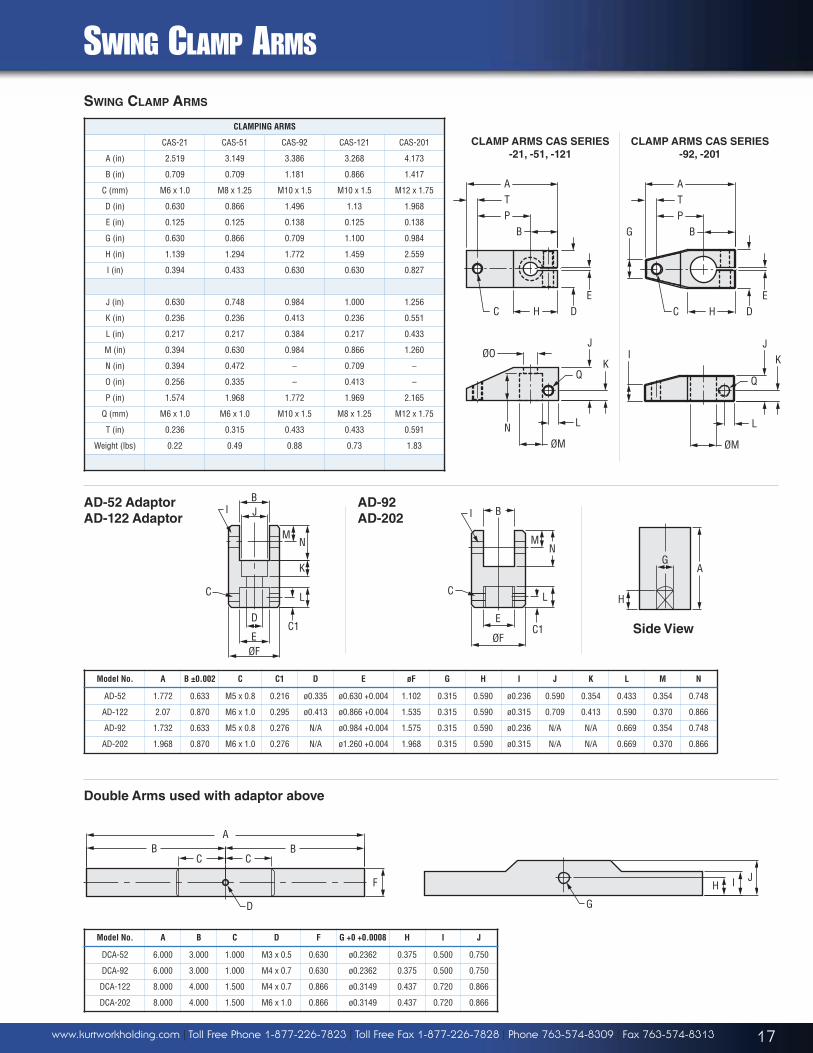
SWING CLAMP ARMS
SWING CLAMP ARMS
CLAMPING ARMS
CAS-21 CAS-51 CAS-92 CAS-121 CAS-201
A (in) 2.519 3.149 3.386 3.268 4.173
B (in) 0.709 0.709 1.181 0.866 1.417
C (mm) M6 x 1.0 M8 x 1.25 M10 x 1.5 M10 x 1.5 M12 x 1.75
D (in) 0.630 0.866 1.496 1.13 1.968
E (in) 0.125 0.125 0.138 0.125 0.138
G (in) 0.630 0.866 0.709 1.100 0.984
H (in) 1.139 1.294 1.772 1.459 2.559
I (in) 0.394 0.433 0.630 0.630 0.827
J (in) 0.630 0.748 0.984 1.000 1.256
K (in) 0.236 0.236 0.413 0.236 0.551
L (in) 0.217 0.217 0.384 0.217 0.433
M (in) 0.394 0.630 0.984 0.866 1.260
N (in) 0.394 0.472 – 0.709 –
O (in) 0.256 0.335 – 0.413 –
P (in) 1.574 1.968 1.772 1.969 2.165
Q (mm) M6 x 1.0 M6 x 1.0 M10 x 1.5 M8 x 1.25 M12 x 1.75
T (in) 0.236 0.315 0.433 0.433 0.591
Weight (lbs) 0.22 0.49 0.88 0.73 1.83
Model No. A B ±0.002 C C1 D E øF G H I J K L M N
AD-52 1.772 0.633 M5 x 0.8 0.216 ø0.335 ø0.630 +0.004 1.102 0.315 0.590 ø0.236 0.590 0.354 0.433 0.354 0.748
AD-122 2.07 0.870 M6 x 1.0 0.295 ø0.413 ø0.866 +0.004 1.535 0.315 0.590 ø0.315 0.709 0.413 0.590 0.370 0.866
AD-92 1.732 0.633 M5 x 0.8 0.276 N/A ø0.984 +0.004 1.575 0.315 0.590 ø0.236 N/A N/A 0.669 0.354 0.748
AD-202 1.968 0.870 M6 x 1.0 0.276 N/A ø1.260 +0.004 1.968 0.315 0.590 ø0.315 N/A N/A 0.669 0.370 0.866
CLAMP ARMS CAS SERIES
-92, -201
A
BPT
DE
HC
CLAMP ARMS CAS SERIES
-21, -51, -121
JK
Q
L
I
ØM
N
K
L
J
Q
ØM
ØO
DE
HC
BPTA
G
Model No. A B C D F G +0 +0.0008 H I J
DCA-52 6.000 3.000 1.000 M3 x 0.5 0.630 ø0.2362 0.375 0.500 0.750
DCA-92 6.000 3.000 1.000 M4 x 0.7 0.630 ø0.2362 0.375 0.500 0.750
DCA-122 8.000 4.000 1.500 M4 x 0.7 0.866 ø0.3149 0.437 0.720 0.866
DCA-202 8.000 4.000 1.500 M6 x 1.0 0.866 ø0.3149 0.437 0.720 0.866
B
D
EC1
MN
K
JI
C L
ØF
C1
MN
L
ØF
E
BI
C
BC C
D
BA
F
Double Arms used with adaptor above
Side View
H I
G
J
A
H
G
AD-52 Adaptor
AD-122 Adaptor
AD-92
AD-202
18 www.kurtworkholding.com | Toll Free Phone 1-877-226-7823 | Toll Free Fax 1-877-226-7828 | Phone 763-574-8309 | Fax 763-574-8313
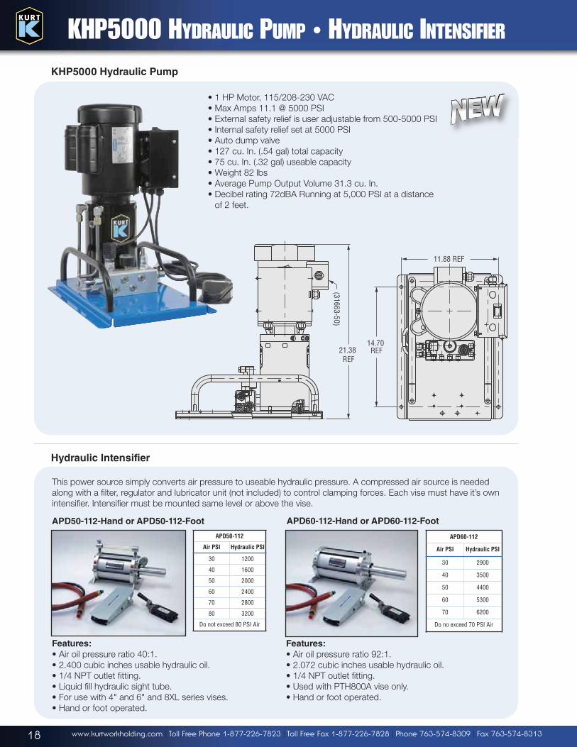
KHP5000 Hydraulic Pump
• 1 HP Motor, 115/208-230 VAC
• Max Amps 11.1 @ 5000 PSI
• External safety relief is user adjustable from 500-5000 PSI
• Internal safety relief set at 5000 PSI
• Auto dump valve
• 127 cu. In. (.54 gal) total capacity
• 75 cu. In. (.32 gal) useable capacity
• Weight 82 lbs
• Average Pump Output Volume 31.3 cu. In.
• Decibel rating 72dBA Running at 5,000 PSI at a distance
of 2 feet.
(31663-50)
21.38 REF
11.88 REF
14.70 REF
KHP5000 HYDRAULIC PUMP • HYDRAULIC INTENSIFIER
Hydraulic Intensifier
Features:
• Air oil pressure ratio 40:1.
• 2.400 cubic inches usable hydraulic oil.
• 1/4 NPT outlet fitting.
• Liquid fill hydraulic sight tube.
• For use with 4" and 6" and 8XL series vises.
• Hand or foot operated.
Features:
• Air oil pressure ratio 92:1.
• 2.072 cubic inches usable hydraulic oil.
• 1/4 NPT outlet fitting.
• Used with PTH800A vise only.
• Hand or foot operated.
This power source simply converts air pressure to useable hydraulic pressure. A compressed air source is needed
along with a filter, regulator and lubricator unit (not included) to control clamping forces. Each vise must have it’s own
intensifier. Intensifier must be mounted same level or above the vise.
APD50-112
Air PSI Hydraulic PSI
30 1200
40 1600
50 2000
60 2400
70 2800
80 3200
Do not exceed 80 PSI Air
APD60-112
Air PSI Hydraulic PSI
30 2900
40 3500
50 4400
60 5300
70 6200
Do no exceed 70 PSI Air
APD60-112-Hand or APD60-112-FootAPD50-112-Hand or APD50-112-Foot
19www.kurtworkholding.com | Toll Free Phone 1-877-226-7823 | Toll Free Fax 1-877-226-7828 | Phone 763-574-8309 | Fax 763-574-8313
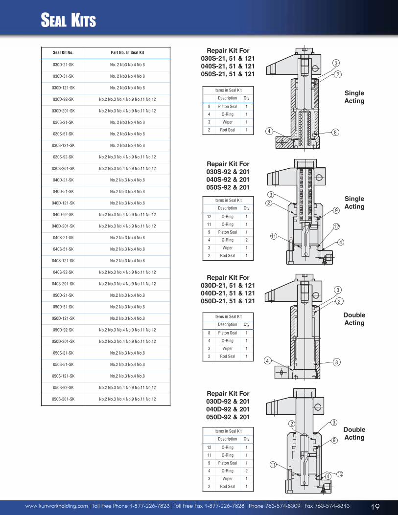
SEAL KITS
Seal Kit No. Part No. In Seal Kit
030D-21-SK No. 2 No3 No 4 No 8
030D-51-SK No. 2 No3 No 4 No 8
030D-121-SK No. 2 No3 No 4 No 8
030D-92-SK No.2 No.3 No.4 No.9 No.11 No.12
030D-201-SK No.2 No.3 No.4 No.9 No.11 No.12
030S-21-SK No. 2 No3 No 4 No 8
030S-51-SK No. 2 No3 No 4 No 8
030S-121-SK No. 2 No3 No 4 No 8
030S-92-SK No.2 No.3 No.4 No.9 No.11 No.12
030S-201-SK No.2 No.3 No.4 No.9 No.11 No.12
040D-21-SK No.2 No.3 No.4 No.8
040D-51-SK No.2 No.3 No.4 No.8
040D-121-SK No.2 No.3 No.4 No.8
040D-92-SK No.2 No.3 No.4 No.9 No.11 No.12
040D-201-SK No.2 No.3 No.4 No.9 No.11 No.12
040S-21-SK No.2 No.3 No.4 No.8
040S-51-SK No.2 No.3 No.4 No.8
040S-121-SK No.2 No.3 No.4 No.8
040S-92-SK No.2 No.3 No.4 No.9 No.11 No.12
040S-201-SK No.2 No.3 No.4 No.9 No.11 No.12
050D-21-SK No.2 No.3 No.4 No.8
050D-51-SK No.2 No.3 No.4 No.8
050D-121-SK No.2 No.3 No.4 No.8
050D-92-SK No.2 No.3 No.4 No.9 No.11 No.12
050D-201-SK No.2 No.3 No.4 No.9 No.11 No.12
050S-21-SK No.2 No.3 No.4 No.8
050S-51-SK No.2 No.3 No.4 No.8
050S-121-SK No.2 No.3 No.4 No.8
050S-92-SK No.2 No.3 No.4 No.9 No.11 No.12
050S-201-SK No.2 No.3 No.4 No.9 No.11 No.12
Repair Kit For
030S-21, 51 & 121
040S-21, 51 & 121
050S-21, 51 & 121
Repair Kit For
030S-92 & 201
040S-92 & 201
050S-92 & 201
Repair Kit For
030D-21, 51 & 121
040D-21, 51 & 121
050D-21, 51 & 121
Repair Kit For
030D-92 & 201
040D-92 & 201
050D-92 & 201
Items in Seal Kit
Description Qty
8 Piston Seal 1
4 O-Ring 1
3 Wiper 1
2 Rod Seal 1
Items in Seal Kit
Description Qty
12 O-Ring 1
11 O-Ring 1
9 Piston Seal 1
4 O-Ring 2
3 Wiper 1
2 Rod Seal 1
Items in Seal Kit
Description Qty
8 Piston Seal 1
4 O-Ring 1
3 Wiper 1
2 Rod Seal 1
Items in Seal Kit
Description Qty
12 O-Ring 1
11 O-Ring 1
9 Piston Seal 1
4 O-Ring 2
3 Wiper 1
2 Rod Seal 1
3
2
4 8
3
2
11
9
12
4
84
2
3
2 3
124
11
9
Single
Acting
Double
Acting
Double
Acting
Single
Acting
Kurt™ Manufacturing Industrial Products Division9445 E. River Road NWMinneapolis, MN 55433Tel: (763) 574-8309Fax: (763) 574-8313Toll Free (US Only): 1 (877) 226-7823Toll Free Fax (US Only): 1 (877) 226-7828Email: [email protected]: www.kurtworkholding.com
Printed in USA © Copyright. All rights reservedLIT.KHSCAT.7.11.2
ONE YEAR LIMITED WARRANTY
For Kurt Branded ProductsAll Kurt Manufacturing Company Industrial HYDRAULIC CLAMPING SYSTEMS products and parts, with the exceptions noted below, are warranted against defects in material and workmanshipfor one year from the distributor invoice date. Failure to properly maintain and/or properly operate the product or part under normal conditions will void this warranty. This warranty does not coverany product or part that has been worn out, abused, heated, ground or otherwise altered, used for a purpose other than that for which it was intended, or used in a manner inconsistent with anyinstructions regarding its use. The sole obligation of Kurt Manufacturing Company, Inc. (“Kurt”) and the purchaser’s SOLE AND EXCLUSIVE REMEDY hereunder, shall be limited to thereplacement or repair of any Kurt product or part (by an authorized Kurt technician) provided that such an item is returned to Kurt’s place of business, transportation, shipping and postal chargesprepaid, and there determined by Kurt Manufacturing Company to be covered by the warranty contained herein.THE LIMITED WARRANTY DESCRIBED HEREIN IS MADE EXPRESSLY IN LIEU OF ANY OTHER EXPRESSED OR IMPLIED WARRANTIES, INCLUDING ANY IMPLIED WARRANTY OFMERCHANTABILITY OR FITNESS FOR A PARTICULAR PURPOSE. KURT MANUFACTURING COMPANY IS NOT RESPONSIBLE FOR THE IMPROPER USE OF ITS PRODUCTS. KURTMANUFACTURING SHALL NOT BE LIABLE FOR ANY DIRECT, INDIRECT, INCIDENTAL, SPECIAL OR CONSEQUENTIAL DAMAGES. INCLUDING BUT NOT LIMITED TO, LOSS OF USE,REVENUE OR PROFIT.
KURT ASSUMES NO LIABILITY FOR, AND MAKES NO WARRANTY REGARDING, ANY PURCHASED ITEMS WHERE THE MANUFACTURER OF SUCH ITEM EXTENDS A SEPARATE WARRANTY.
Distributor
Safety Notes:
• Upon receipt of components check for any damage that may have occurred during shipping.• Always keep hands away from cylinders when clamping and unclamping avoiding pinch points.• If a hose or hydraulic line becomes bent or kinked replace it immediately.• Most Kurt cylinders are designed to operate at 5000 PSI Max. Refer to catalog for rating of individual components.• Remove any trapped air from system before operating.• Never attempt to uncouple quick disconnects while system is under pressure.• Never exceed the pressure rating of the systems lowest component as this would be the maximum pressure
setting. This includes clamp, hoses, fittings etc.• Never handle a pressurized hose as the smallest leak can penetrate the skin.• If system develops a leak find it and repair it immediately.• Think safety first and always use common sense while running any hydraulic component.