Embed Size (px)
Citation preview
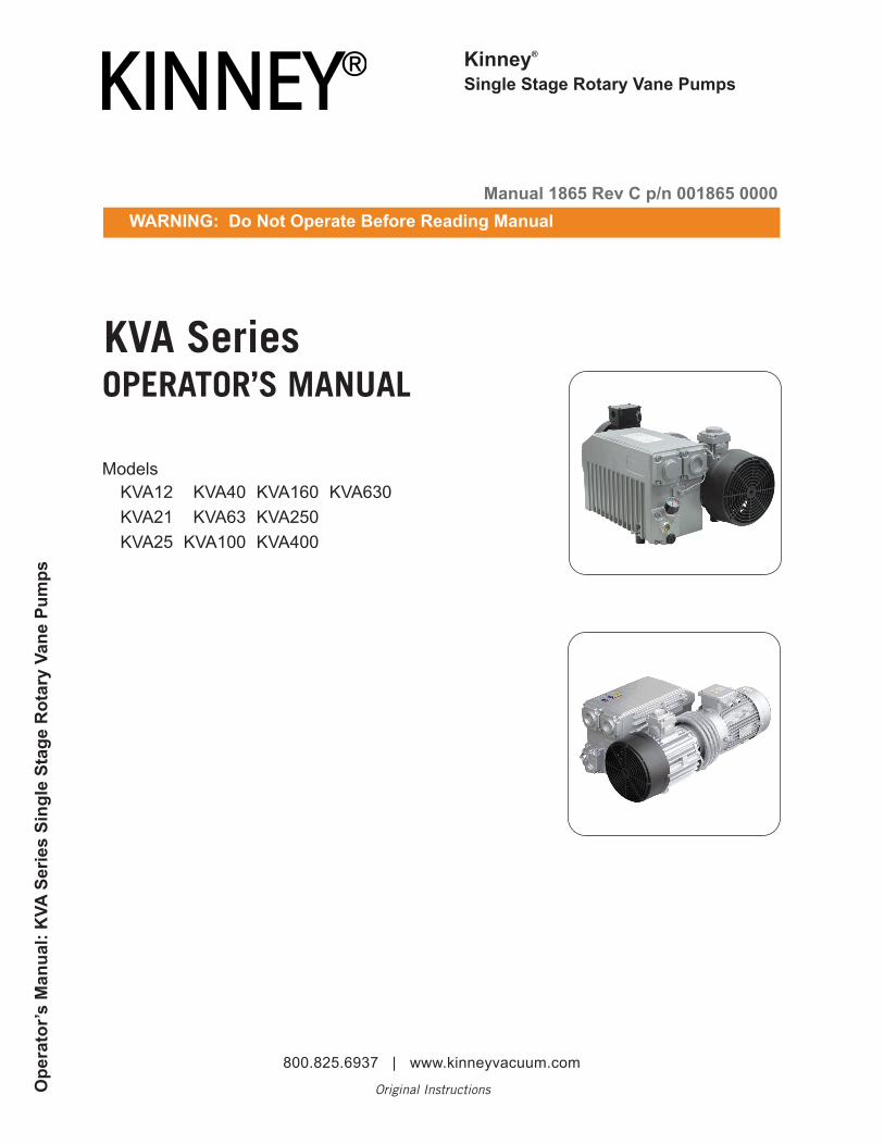
Kinney®
Single Stage Rotary Vane Pumps
KVA Series
Models KVA12 KVA40 KVA160 KVA630KVA21 KVA63 KVA250KVA25 KVA100 KVA400
OPERATOR’S MANUAL
Manual 1865 Rev C p/n 001865 0000WARNING: Do Not Operate Before Reading Manual
Ope
rato
r’s M
anua
l: K
VA S
erie
s Si
ngle
Sta
ge R
otar
y Va
ne P
umps
800.825.6937 | www.kinneyvacuum.com
Original Instructions
Disclaimer Statement:All information, illustrations and specifications in this manual are based on the latest infor-mation available at the time of publishing. The illustrations used in this manual are intended as representative reference views only. Products are under a continuous improvement policy. Thus, information, illustrations and/or specifications to explain and or exemplify a product, service or maintenance improvement may be changed at any time without notice.
Rights Reserved Statement:No part of this publication may be reproduced or used in any form by any means - graphic, electronic or mechanical, including photocopying, recording, taping or information storage and retrieval systems - without the written permission of Kinney®.
Product information and specifications subject to change.
iManual 1865 Rev C p/n 001865 0000
Table of Contents
Table of ContentsIntroduction .................................................................................. 1Safety ............................................................................................ 2
Graphic Conventions Used in this Manual ............................................ 2
Safety Instruction Tag ........................................................................... 2
Safety Precautions for Vane Pumps ...................................................... 2
Installation .................................................................................... 4Unpacking ............................................................................................. 4
Location ................................................................................................ 4
Power Requirements ............................................................................. 4
Vacuum Connections ............................................................................ 5
Filling the Pump With Oil ....................................................................... 5
Operation ...................................................................................... 6Start-Up ................................................................................................. 6
Stopping the Pump ............................................................................... 6
Gas Ballast ............................................................................................ 6
Maintenance ................................................................................. 7Inline (Inlet) Filter ................................................................................... 7
Oil Level ................................................................................................ 7
Oil Type and Quantity ........................................................................... 7
Oil Change ............................................................................................ 7
Oil Spin-On Filter ................................................................................... 8
Exhaust Filter ......................................................................................... 8
ii
Table of Contents
Manual 1865 Rev C p/n 001865 0000
Overhaul Kit and Accessories............................................................... 8
Maintenance Schedule ......................................................................... 8
Specifications ............................................................................... 9Troubleshooting ......................................................................... 10Exploded Views and Parts Lists ............................................... 13
KVA12/21TNM Exploded View Drawing .............................................. 14
KVA12/21TMN Parts List ..................................................................... 15
KVA25/40TH Exploded View Drawing ................................................. 16
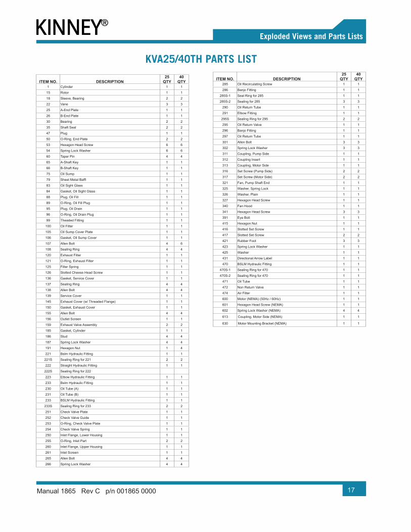
KVA25/40TH Parts List ........................................................................ 17
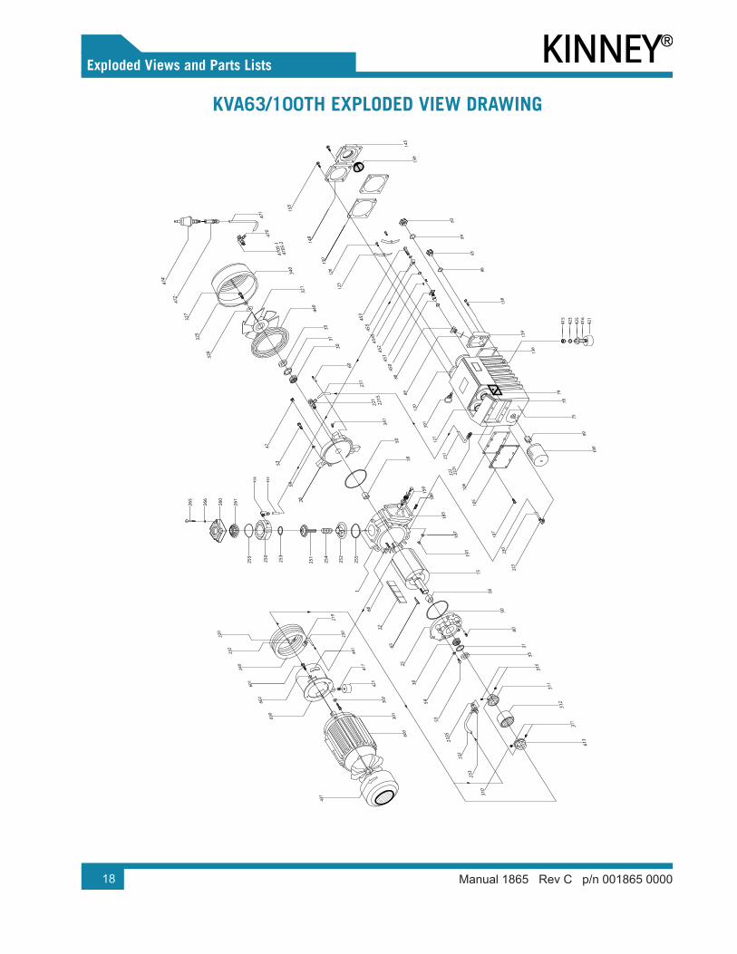
KVA63/100TH Exploded View Drawing ............................................... 18
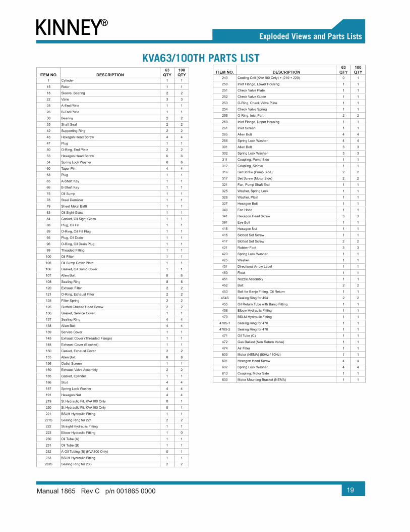
KVA63/100TH Parts List ...................................................................... 19
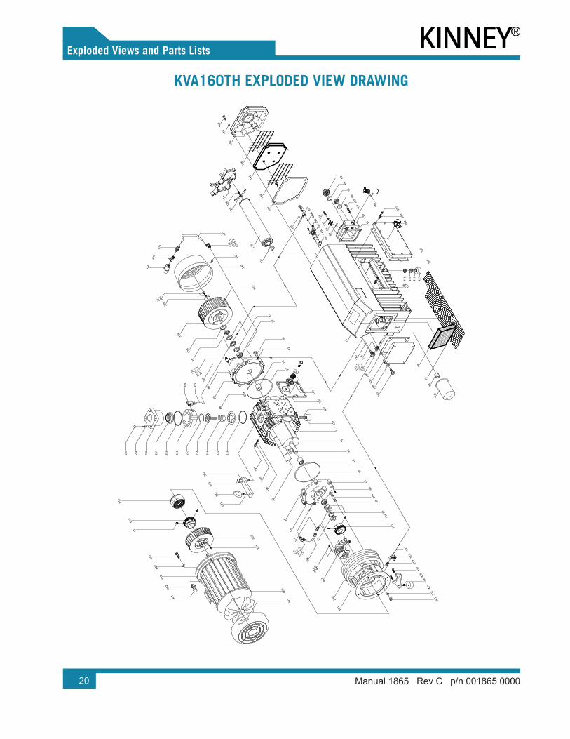
KVA160TH Exploded View Drawing .................................................... 20
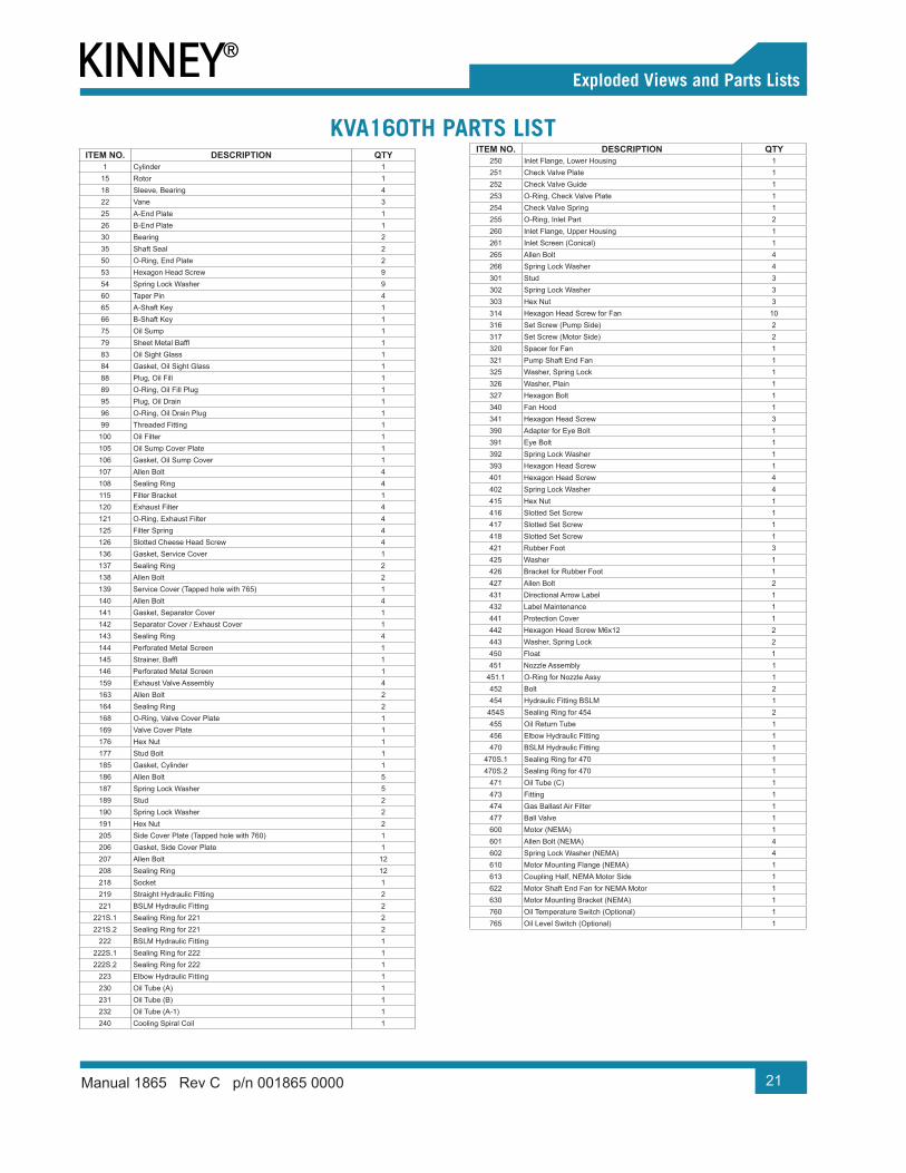
KVA160TH Parts List ........................................................................... 21
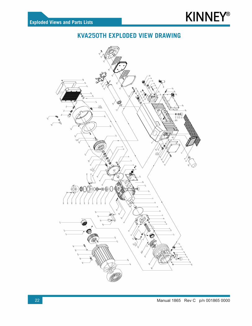
KVA250TH Exploded View Drawing .................................................... 22
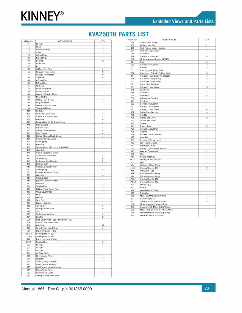
KVA250TH Parts List ........................................................................... 23
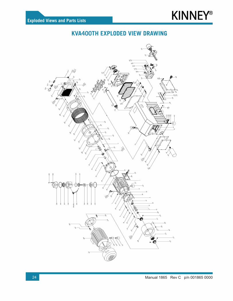
KVA400TH Exploded View Drawing .................................................... 24
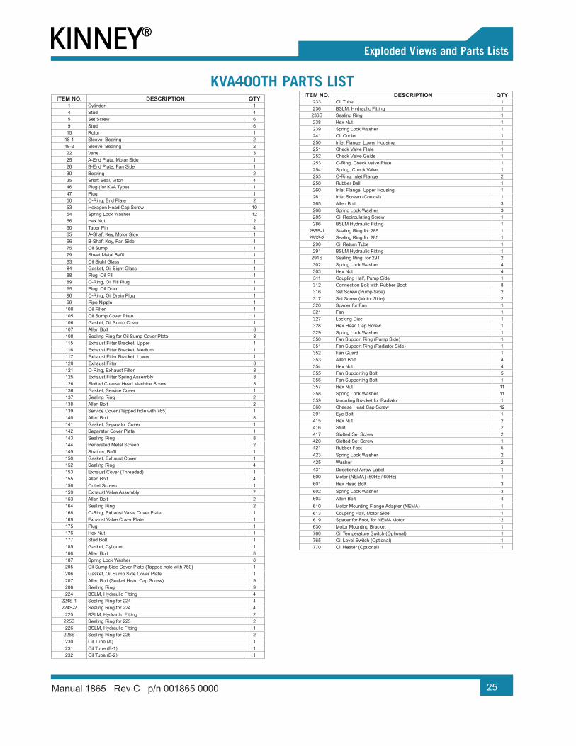
KVA400TH Parts List ........................................................................... 25
KVA630TH Exploded View Drawing .................................................... 26
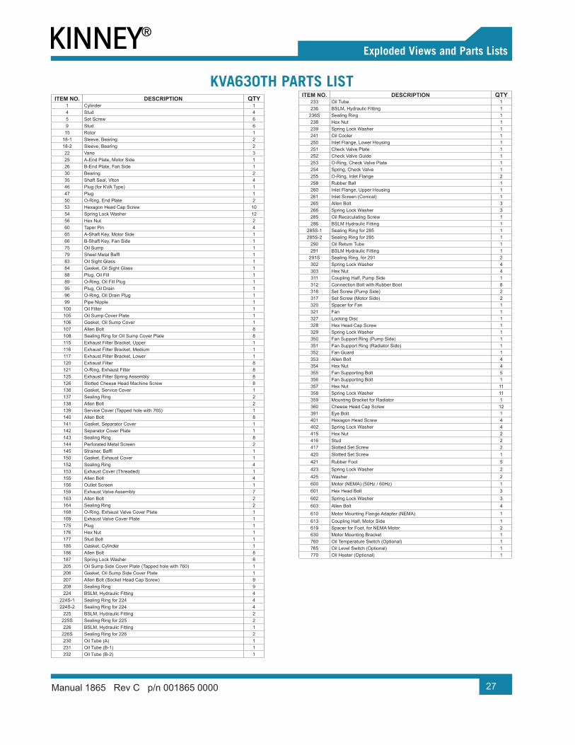
KVA630TH Parts List ........................................................................... 27
Warranty – Vacuum Products ................................................... 28Operating Data Form / Product Registration ........................... 29
1Manual 1865 Rev C p/n 001865 0000
CONGRATULATIONS on your purchase of a new Kinney® KVA oil lubricated, rotary vane vacuum pump. Please examine the pump for shipping damage, and if any damage is found, report it immediately to the carrier. If the pump is to be installed at a later date, make sure it is stored in a clean, dry location and rotated regularly. Make sure covers are kept on all openings. If the pump is stored outdoors, be sure to protect it from weather and corrosion.
Kinney KVA vacuum pumps are built to exacting standards and, if properly installed and maintained, will provide many years of reliable service. Read and follow every step of these instructions when installing and maintaining the pump.
This manual covers KVA model vacuum pumps. Please identify the model number and serial number when ordering parts.
WARNING!Serious injury can result from operating or repairing this machine without first reading the service manual and taking adequate safety precautions.
OTE: N Record the model and serial numbers of the pump in the OPERATING DATA form on the inside back cover of this manual. Use this identification on any replacement part orders, or if service or application assistance is required.
INTRODUCTION
01
2 Manual 1865 Rev C p/n 001865 0000
GRAPHIC CONVENTIONS USED IN THIS MANUAL
The following hazard levels are referenced within this manual:
DANGER!Indicates a hazardous situation that, if not avoided, will result in death or serious injury.
WARNING!Indicates a hazardous situation that, if not avoided, could result in death or serious injury.
CAUTION!Indicates a hazardous situation that, if not avoided, could result in minor or moderate injury.
Indicates a situation that can cause damage to the pump, personal property, and/or the environment or cause the equipment to operate improperly.
OTE: N Indicates a procedure, practice, or condition that should be followed in order for the equipment to function in the manner intended.
SAFETY INSTRUCTION TAG
CAUTION!Do not valve or restrict pump discharge opening.
Use oil mist eliminator when operating pump, ensure adequate ventilation when discharging indoors.
Refer to manual safety instructions.
SAFETY PRECAUTIONS FOR VANE PUMPS
Please read the following safety information before operating the vacuum pump.
• Do not operate the pump without the guards properly attached. Disconnect the pump motor from the electrical supply at the main disconnect before removing the guards. Replace the belt guard before reconnecting the power supply to the pump motor. Operating the pump without the belt guard properly installed exposes personnel in the vicinity of the pump to risk from rotating drive components.
SAFETY
02
3
02Safety
Manual 1865 Rev C p/n 001865 0000
• Do not operate the pump with oxygen-enriched gas (greater than 23.5% by volume) in the suction line, unless the pump has been prepared with an inert fluid suitable for the application andequipped with seal and start/stop purge system.
WARNING!Pumping oxygen-enriched gases with mineral oil or other non-inert fluids and without proper purges can cause fire or explosion in the pump, resulting in damage or serious bodily injury.
• Take precautions to avoid prolonged or excessive exposure to oil mist or process materials emanating from the discharge of the pump.
• Do not allow the pump to discharge into a closed or inadequately ventilated room. Where process vapor contains environmentally unfriendly chemical vapor, pump discharge must be connected to the properly sized scrubber system to neutralize the harmful chemicals prior to the discharge to the atmosphere. Laws and ordinances may pertain to your local area regarding discharge of oil mist, oil vapor, or chemical vapor to atmosphere. Check local laws and ordinances before operating the pump with discharge to outside atmosphere.
• Do not restrict the pump discharge in any way or place valves in the discharge line. The vacuum pump is a compressor and will generate high pressures without stalling the motor when operated at low suction pressures. Excessive pressure could cause damage or serious bodily injury.
• Disconnect the pump motor from the electrical supply at the main disconnect before disassembling or servicing the pump. Make sure that the pump is completely reassembled, the guards are properly installed, and all fill anddrain valves are installed and closed before reconnecting the power supply. Accidental start-up or operation of the pump while maintenance is in progress could cause damage or serious bodily injury.
• Lift the pump only by the lifting lugs supplied with the pump. Never lift equipment attached to the pump by the pump lifting lugs.
• Do not touch hot surfaces on the pump. In normal operation at low pressures, surface temperatures will not normally exceed 180°F (82°C). Prolonged operation at 200 Torr (267 mbar) may cause surface temperatures as high as 220°F (104°C).
4 Manual 1865 Rev C p/n 001865 0000
UNPACKING
Inspect the box and pump carefully for any signs of damage incurred in transit. Since all pumps are ordinarily shipped F.O.B. from our factory or regional warehouse, such damage is normally the responsibility of the carrier and should be reported to them.
The vacuum pump is bolted to the skid. To free the pump, remove the fasteners.
The inlet and exhaust of the pump are covered with plastic caps to prevent dirt and other foreign substances from entering the pump. Leave these caps in place until you are ready to pipe the pump to your equipment.
LOCATION
Install the pump in a horizontal position on a level surface so that the pump is evenly supported on its rubber feet. Leave 12 – 18 in. (30 – 46 cm) of access around the pump to allow proper cooling. Provide adequate ventilation for the fans, radiator, and motor.
Allow easy access to the oil sight glass for inspection of the oil level, and allow easy access to the exhaust port for filter changes. Do not tip overthe pump if it is filled with oil
POWER REQUIREMENTS
A schematic diagram for the electrical motor terminal connections is located in the junction box of the motor or on the motor nameplate.
Connect the motor according to the electrical codes through a fused switch in order to protect the motor against electrical or mechanical overload conditions. Set the overload of the motor starter at a level equal to the full load motor current listed on the motor nameplate.
If the pump is supplied with a motor starter, it is preset at the factory according to customer specifications. Check that these settings are inline with the voltage at your location. If the voltage is different, please contact Kinney for motor and starter information.
Correct direction of rotation is marked by an arrow on the motor fan housing and is counterclockwise when looking at the motor from the motor’s fan side.
OTE: N After electrical connections have been made but before oil has been added, check the rotation of the motor. If rotation is backward, reverse any two leads of the three at the power connection.
INSTALLATION
03
5
03Installation
Manual 1865 Rev C p/n 001865 0000
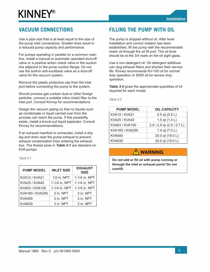
VACUUM CONNECTIONS
Use a pipe size that is at least equal to the size of the pump inlet connections. Smaller lines result in a reduced pump capacity and performance.
For pumps operating in parallel on a common main line, install a manual or automatic operated shut-off valve or a positive action check valve in the suction line adjacent to the pump suction flange. Do notuse the built-in anti-suckback valve as a shut-off valve for the vacuum system.
Remove the plastic protective cap from the inlet port before connecting the pump to the system.
Should process gas contain dust or other foreign particles, connect a suitable inline (inlet) filter to theinlet port. Consult Kinney for recommendations.
Design the vacuum piping so that no liquids such as condensate or liquid carried over from the process can reach the pump. If this possibility exists, install a knock-out liquid separator. Consult Kinney for recommendations.
If an exhaust manifold is connected, install a drip leg and drain near the pump exhaust to prevent exhaust condensation from entering the exhaust box. The thread sizes in Table 3-1 are standard on KVA pumps:
Table 3-1
PUMP MODEL INLET SIZE EXHAUST SIZE
KVA12 / KVA21 1/2 in. NPT 1-1/4 in. NPTKVA25 / KVA40 1-1/4 in. NPT 1-1/4 in. NPTKVA63 / KVA100 1-1/4 in. NPT 1-1/4 in. NPTKVA160 / KVA250 2 in. NPT 2 in. NPTKVA400 3 in. NPT 3 in. NPTKVA630 3 in. NPT 3 in. NPT
FILLING THE PUMP WITH OIL
The pump is shipped without oil. After level installation and correct rotation has been established, fill the pump with the recommendedmotor oil through the oil fill port. The oil level should be at the 3/4 mark on the oil sight glass.
Use a non-detergent oil. Oil detergent additives can clog exhaust filters and shorten their servicelife. Kinney recommends KV-100 oil for normal duty operation or S500 oil for severe duty operation.
Table 3-2 gives the approximate quantities of oil required for each model.
Table 3-2
PUMP MODEL OIL CAPACITYKVA12 / KVA21 0.5 qt (0.5 L)KVA25 / KVA40 1.5 qt (1.4 L)KVA63 / KVA100 2.6 / 2.9 qt (2.5 / 2.7 L)KVA160 / KVA250 7.4 qt (7.0 L)KVA400 20.0 qt (19.0 L)KVA630 20.0 qt (19.0 L)
WARNING!Do not add or fill oil with pump running or through the inlet or exhaust ports! Do not overfill.
6 Manual 1865 Rev C p/n 001865 0000
START-UP
Check rotation of the motor as described in Power Requirements on page 4. Fill the pump with oil as described in Filling the Pump With Oil on page 5.
Start the pump with the inlet closed. Run the pump for a few minutes and then shut it down. Check the oil level again and make sure the oil level is between the 3/4 mark and the FULL mark on the oil sight glass.
Add oil, if necessary. Add pump oil only when the pump is off and circulating oil has sufficient time toreturn to the oil sump.
STOPPING THE PUMP
To stop the pump, turn off the power. A built-in anti-suckback valve will prevent oil in the oil reservoir from being sucked back into the cylinder after the pump is shut down. Do not use the anti-suckback valve as a check valve. Consult Kinney for proper check valves.
GAS BALLAST
KVA pumps (KVA125TH and larger) are equipped with a gas ballast. The gas ballast valve is located between the inlet port and the exhaust box. Its main function is to prevent water vapor from condensing in the pump, which causes emulsification of the oil that can result i pump failure.
In applications when the quantity of water vapor is moderate, Kinney recommends running the pump for 10 minutes to its normal operating temperature prior to going on process. Also operate the pump off process for 10 minutes prior to shutdown. A slight air bleed (purge) is recommended during these 10-minute cycles to prevent the vapor from condensing in the pump.
OPERATION
04
7Manual 1865 Rev C p/n 001865 0000
KVA Series vacuum pumps require very little maintenance. To ensure optimum performance, perform the following maintenance procedures.
INLINE (INLET) FILTER
Check the inline (inlet) filter on a weekly basis.Clean or replace the filter cartridge when it is dirt . Consult Kinney for part numbers and replacement element information.
CAUTION!Depending on the mounting position of the filter, be careful not to allow accumulated foreign material to fall in the pump suction inlet when removing the filter cartridge. Horizontal filter installation is recommended to prevent this.
OIL LEVEL
Under normal circumstances, adding oil between oil changes should not be necessary. A significantdrop in oil level means there is either an oil leak, a defective exhaust filter or O-ring, or a leaking antisuckback valve.
If the pump is smoking excessively, the exhaust filter may be installed improperl .
It is normal for the oil to be foamy or lightly colored in an operating pump. This may be normal aeration of the oil. If the oil appears milky or dark colored, it is contaminated or burned and must be changed.
Check the oil level only when the pump is shut off. Replenish oil if it drops below the 3/4 mark of the oil sight glass. Add oil through the oil fill port onl .
CAUTION!Do not add oil while the pump is running, since hot oil can escape from the oil fill port.
OIL TYPE AND QUANTITY
See “Filling the Pump With Oil” on page 5 for details on oil type and quantity.
OIL CHANGE
Oil change frequency depends on the application and ambient temperature. Kinney recommends that the customer monitor the condition of the oil. When using KV-100 oil, Kinney recommends changing the oil every 500 – 750 operating hours. When using S500 oil, Kinney recommends changing the oil every 750 – 1,000 operating hours.
MAINTENANCE
05
8
05Maintenance
Manual 1865 Rev C p/n 001865 0000
OIL SPIN-ON FILTER
Replace the spin-on filter at every oil change.Please consult Kinney’ authorized representative for part numbers.
EXHAUST FILTER
Replace the exhaust filters every 9 to 18 monthsof operation or as necessary. The service life of the exhaust filters varies depending upon theapplication and frequency of oil change. It is necessary to change the exhaust filters only whenthey become clogged. Indications of clogged exhaust filters are smoke or oil mist coming fromthe exhaust of the pump, a higher than normal motor current, or an exhaust pressure gauge reading of 3 psig (21 kPa) or greater.
Do not clean or re-use exhaust filters. Dispose of the exhaust filters properly as they might contain toxic substances carried over from the process. Replace the O-rings on the exhaust filter when changing it.
Please consult a Kinney authorized representative for part numbers.
OVERHAUL KIT AND ACCESSORIES
An overhaul kit contains a set of gaskets, O-rings, vanes, bearing, bearing sleeves, shaft seals, and taper pins. Please consult a Kinney authorized representative for part numbers.
MAINTENANCE SCHEDULE
The operating life of the pump is greatly affected by the oil quality and filter condition. Periodicmaintenance will ensure a reliably operating vacuum pump.
Daily: Visually check oil level and color.
Weekly: Inspect inline (inlet) filte .
Monthly: Check the exhaust filte ’s function.
Every 2 – 6 months: Drain and discard oil from pump while hot. Refill with fresh oil
Every 9 – 18 months: Replace exhaust filterelements and O-ring.
Every 500 – 2,000 Operating hours: Change the oil and oil filte . In models equipped with the floatvalve with a return line, check the float valve s operating conditions.
See the motor manufacturer’s manual for the periodic motor maintenance.
9Manual 1865 Rev C p/n 001865 0000
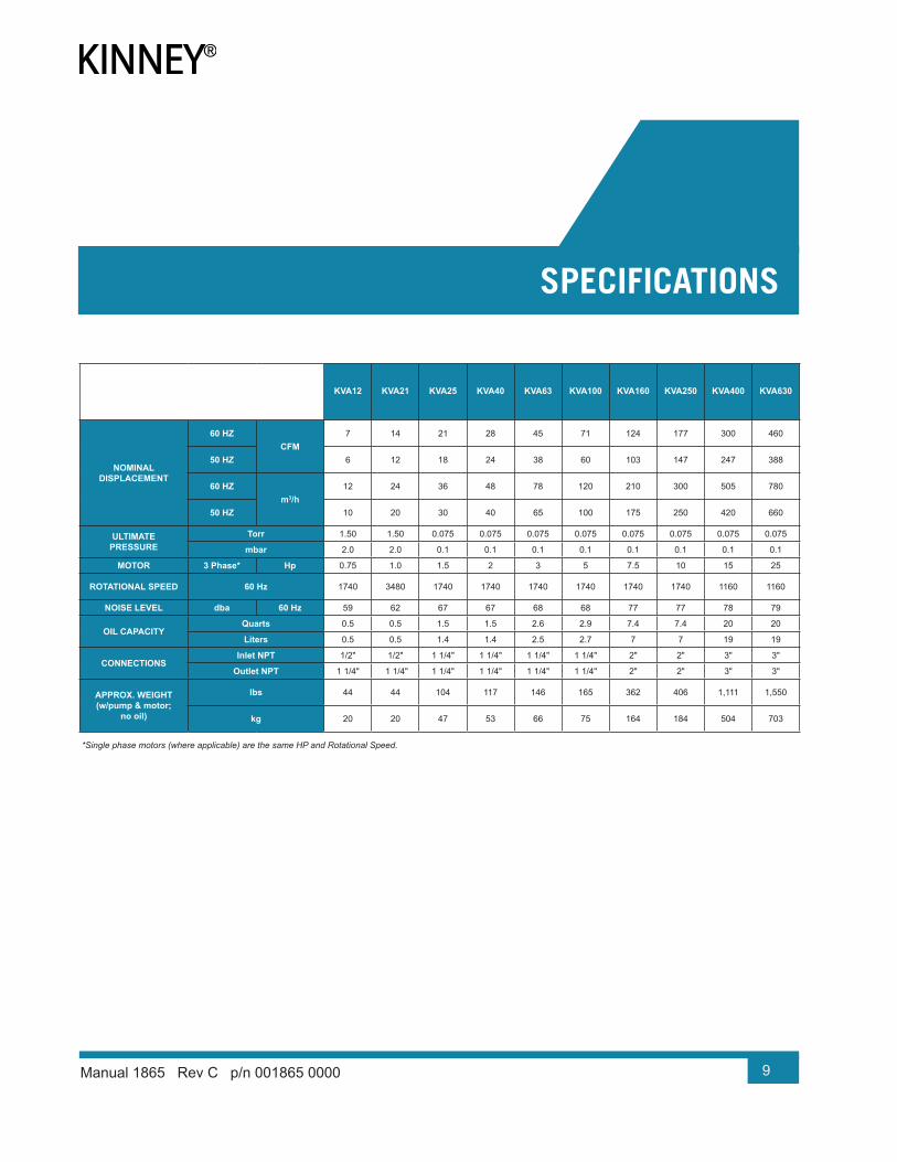
KVA12 KVA21 KVA25 KVA40 KVA63 KVA100 KVA160 KVA250 KVA400 KVA630
NOMINAL DISPLACEMENT
60 HZCFM
7 14 21 28 45 71 124 177 300 460
50 HZ 6 12 18 24 38 60 103 147 247 388
60 HZm3/h
12 24 36 48 78 120 210 300 505 780
50 HZ 10 20 30 40 65 100 175 250 420 660
ULTIMATE PRESSURE
Torr 1.50 1.50 0.075 0.075 0.075 0.075 0.075 0.075 0.075 0.075
mbar 2.0 2.0 0.1 0.1 0.1 0.1 0.1 0.1 0.1 0.1
MOTOR 3 Phase* Hp 0.75 1.0 1.5 2 3 5 7.5 10 15 25
ROTATIONAL SPEED 60 Hz 1740 3480 1740 1740 1740 1740 1740 1740 1160 1160
NOISE LEVEL dba 60 Hz 59 62 67 67 68 68 77 77 78 79
OIL CAPACITYQuarts 0.5 0.5 1.5 1.5 2.6 2.9 7.4 7.4 20 20
Liters 0.5 0.5 1.4 1.4 2.5 2.7 7 7 19 19
CONNECTIONSInlet NPT 1/2" 1/2" 1 1/4" 1 1/4" 1 1/4" 1 1/4" 2" 2" 3" 3"
Outlet NPT 1 1/4" 1 1/4" 1 1/4" 1 1/4" 1 1/4" 1 1/4" 2" 2" 3" 3"
APPROX. WEIGHT (w/pump & motor;
no oil)
lbs 44 44 104 117 146 165 362 406 1,111 1,550
kg 20 20 47 53 66 75 164 184 504 703
*Single phase motors (where applicable) are the same HP and Rotational Speed.
06SPECIFICATIONS
10 Manual 1865 Rev C p/n 001865 0000
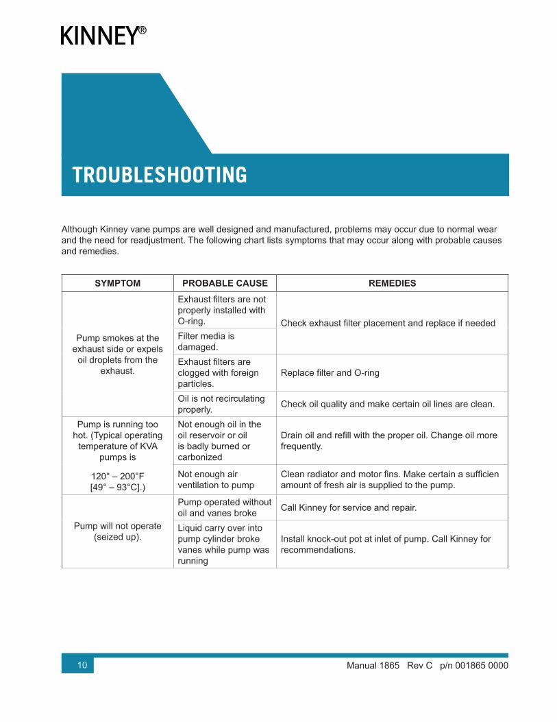
Although Kinney vane pumps are well designed and manufactured, problems may occur due to normal wear and the need for readjustment. The following chart lists symptoms that may occur along with probable causes and remedies.
SYMPTOM PROBABLE CAUSE REMEDIES
Pump smokes at the exhaust side or expels
oil droplets from the exhaust.
Exhaust filters are notproperly installed with O-ring. Check exhaust filter placement and replace if neededFilter media is damaged.Exhaust filters areclogged with foreign particles.
Replace filter and O-ring
Oil is not recirculating properly. Check oil quality and make certain oil lines are clean.
Pump is running too hot. (Typical operating
temperature of KVA pumps is
120° – 200°F [49° – 93°C].)
Not enough oil in the oil reservoir or oil is badly burned or carbonized
Drain oil and refill with the proper oil. Change oil morefrequently.
Not enough air ventilation to pump
Clean radiator and motor fins. Make certain a sufficienamount of fresh air is supplied to the pump.
Pump will not operate (seized up).
Pump operated without oil and vanes broke Call Kinney for service and repair.
Liquid carry over into pump cylinder broke vanes while pump was running
Install knock-out pot at inlet of pump. Call Kinney for recommendations.
TROUBLESHOOTING
07
11
07Troubleshooting
Manual 1865 Rev C p/n 001865 0000
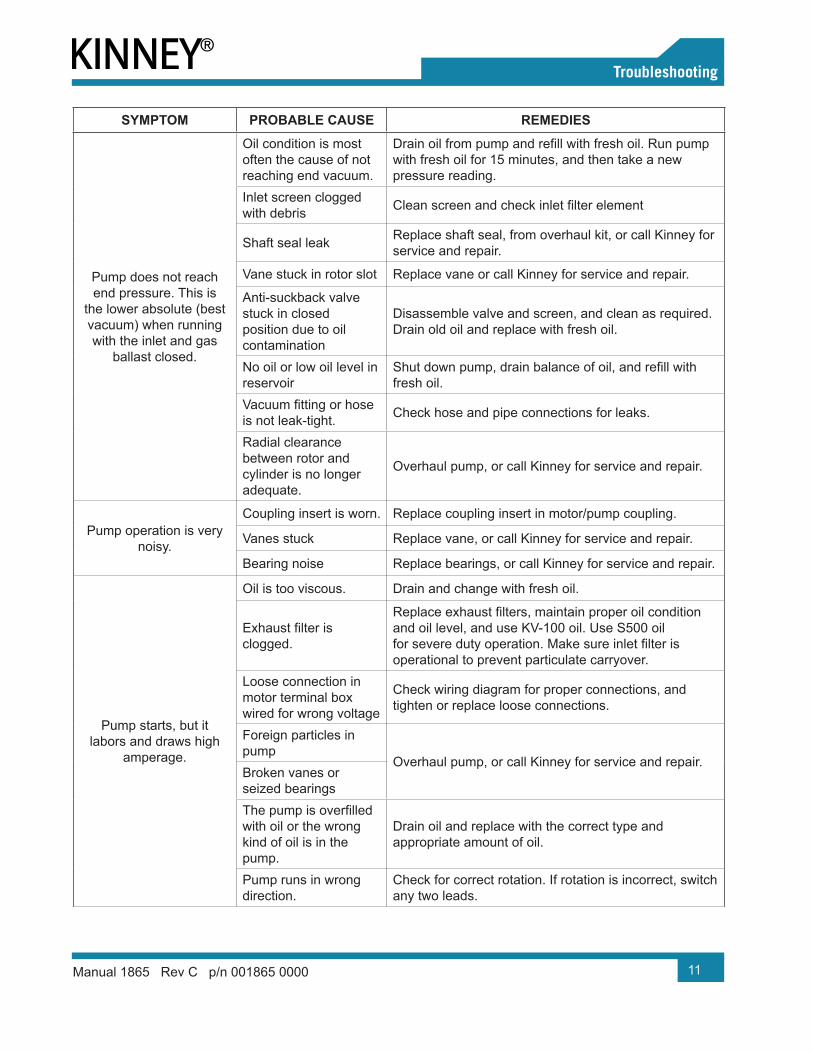
SYMPTOM PROBABLE CAUSE REMEDIES
Pump does not reach end pressure. This is
the lower absolute (best vacuum) when running with the inlet and gas
ballast closed.
Oil condition is most often the cause of not reaching end vacuum.
Drain oil from pump and refill with fresh oil. Run pumpwith fresh oil for 15 minutes, and then take a new pressure reading.
Inlet screen clogged with debris Clean screen and check inlet filter element
Shaft seal leak Replace shaft seal, from overhaul kit, or call Kinney for service and repair.
Vane stuck in rotor slot Replace vane or call Kinney for service and repair.
Anti-suckback valve stuck in closed position due to oil contamination
Disassemble valve and screen, and clean as required. Drain old oil and replace with fresh oil.
No oil or low oil level in reservoir
Shut down pump, drain balance of oil, and refill withfresh oil.
Vacuum fitting or hoseis not leak-tight. Check hose and pipe connections for leaks.
Radial clearance between rotor and cylinder is no longer adequate.
Overhaul pump, or call Kinney for service and repair.
Pump operation is very noisy.
Coupling insert is worn. Replace coupling insert in motor/pump coupling.
Vanes stuck Replace vane, or call Kinney for service and repair.
Bearing noise Replace bearings, or call Kinney for service and repair.
Pump starts, but it labors and draws high
amperage.
Oil is too viscous. Drain and change with fresh oil.
Exhaust filter isclogged.
Replace exhaust filters, maintain proper oil conditionand oil level, and use KV-100 oil. Use S500 oil for severe duty operation. Make sure inlet filter isoperational to prevent particulate carryover.
Loose connection in motor terminal box wired for wrong voltage
Check wiring diagram for proper connections, and tighten or replace loose connections.
Foreign particles in pump
Overhaul pump, or call Kinney for service and repair.Broken vanes or seized bearingsThe pump is overfilledwith oil or the wrong kind of oil is in the pump.
Drain oil and replace with the correct type and appropriate amount of oil.
Pump runs in wrong direction.
Check for correct rotation. If rotation is incorrect, switch any two leads.
12
07Troubleshooting
Manual 1865 Rev C p/n 001865 0000
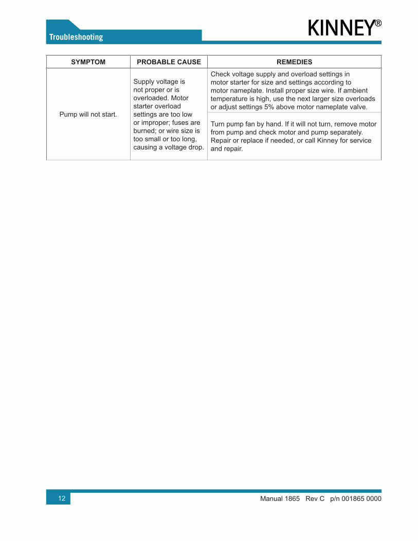
SYMPTOM PROBABLE CAUSE REMEDIES
Pump will not start.
Supply voltage is not proper or is overloaded. Motor starter overload settings are too low or improper; fuses are burned; or wire size is too small or too long, causing a voltage drop.
Check voltage supply and overload settings in motor starter for size and settings according to motor nameplate. Install proper size wire. If ambient temperature is high, use the next larger size overloads or adjust settings 5% above motor nameplate valve.
Turn pump fan by hand. If it will not turn, remove motor from pump and check motor and pump separately. Repair or replace if needed, or call Kinney for service and repair.
13Manual 1865 Rev C p/n 001865 0000
For your convenience, Kinney has prepared a variety of kits to serve all levels of routine and atypical maintenance of your KVA vane pump.
Pump Module
This is an assembled bare pumping chamber, including items 1-66 (as applicable); see Exploded Views and Parts Lists on the following pages for details.
A pump module is often an economical option to replacing a pump, which reuses the existing oil-handling assembly, motor, and accessories, while replacing the rotating components and pumping chamber.
Rebuild Kit
This kit includes (as applicable): a full set of vanes, o-rings, filters, gaskets, bearing, bearing sleeve,shaft seal, coupling boot, and inlet screen.
Gasket Kit
This kit includes (as applicable): shaft seal, end plate o-ring, oil fill o-ring, oil drain o-ring, exhaustfilter o-rings, oil sump gasket, service cover gasket,exhaust cover gasket, exhaust valve seat, cylinder gasket, check valve plate o-ring, float valve o-ring
Filter Kit
This kit includes (as applicable): a full set of exhaust filters, oil filt , oil fill o-ring, oil drain o-ring,exhaust filter o-rings, cover gasket, baffle strain .
Coupling Kit
This kit includes (as applicable): the motor- and pump-side coupling halves and cooling fan.
Inlet Check Valve Kit
This kit includes (as applicable): inlet screen, inlet flange, o-rings, check valve spring, check valveguide, check valve plate.
Vanes
Sold individually, three required per pump; a full set is included in the Rebuild Kit.
Exhaust Filters
Sold individually, refer to Item 120 in the relevant Parts List on the following pages for quantities; a full set is included in the Filter Kit.
Spin-On Oil Filters
Also included in the Filter Kit.
Shaft Seals
Also included in the Rebuild Kit.
08EXPLODED VIEWS AND PARTS LISTS
14
08Exploded Views and Parts Lists
Manual 1865 Rev C p/n 001865 0000
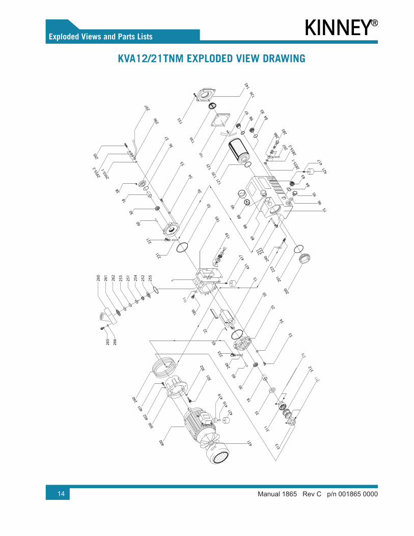
KVA12/21TNM EXPLODED VIEW DRAWING
431
400
300
402
401
240
421
416
419
301
302
313
312
311
35
18
30
233
60
25
50
65
22
15
53
54
1
231
186
221
50
26
6030
1838
421
185
159
54
53
3637
200
201
240
231
89
88
121
120
125
126
156
9695
8483
421
297
286 28
5
8483
417
417
150
155
145
265
266
260
261
262
253
251
254
252
255
75
223
240
285S
-128
5S-2
296
297
295S
-1
295
222
295S
-2
8890
9897
15
05Exploded Views and Parts Lists
Manual 1865 Rev C p/n 001865 0000
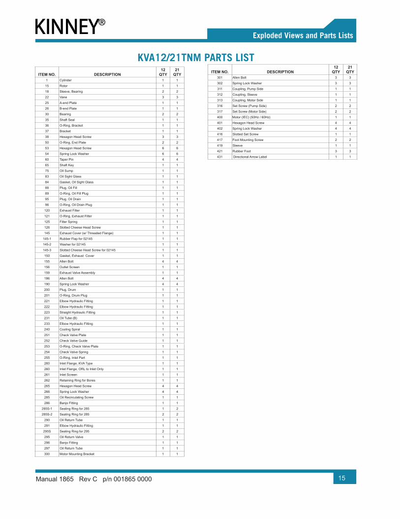
KVA12/21TNM PARTS LISTITEM NO. DESCRIPTION
12 QTY
21 QTY
1 Cylinder 1 1
15 Rotor 1 1
18 Sleeve, Bearing 2 2
22 Vane 3 3
25 A-end Plate 1 1
26 B-end Plate 1 1
30 Bearing 2 2
35 Shaft Seal 1 1
36 O-Ring, Bracket 1 1
37 Bracket 1 1
38 Hexagon Head Screw 3 3
50 O-Ring, End Plate 2 2
53 Hexagon Head Screw 6 6
54 Spring Lock Washer 6 6
60 Taper Pin 4 4
65 Shaft Key 1 1
75 Oil Sump 1 1
83 Oil Sight Glass 1 1
84 Gasket, Oil Sight Glass 1 1
88 Plug, Oil Fill 1 1
89 O-Ring, Oil Fill Plug 1 1
95 Plug, Oil Drain 1 1
96 O-Ring, Oil Drain Plug 1 1
120 Exhaust Filter 1 1
121 O-Ring, Exhaust Filter 1 1
125 Filter Spring 1 1
126 Slotted Cheese Head Screw 1 1
145 Exhaust Cover (w/ Threaded Flange) 1 1
145-1 Rubber Flap for 02145 1 1
145-2 Washer for 02145 1 1
145-3 Slotted Cheese Head Screw for 02145 1 1
150 Gasket, Exhaust Cover 1 1
155 Allen Bolt 4 4
156 Outlet Screen 1 1
159 Exhaust Valve Assembly 1 1
186 Allen Bolt 4 4
190 Spring Lock Washer 4 4
200 Plug, Drum 1 1
201 O-Ring, Drum Plug 1 1
221 Elbow Hydraulic Fitting 1 1
222 Elbow Hydraulic Fitting 1 1
223 Straight Hydraulic Fitting 1 1
231 Oil Tube (B) 1 1
233 Elbow Hydraulic Fitting 1 1
240 Cooling Spiral 1 1
251 Check Valve Plate 1 1
252 Check Valve Guide 1 1
253 O-Ring, Check Valve Plate 1 1
254 Check Valve Spring 1 1
255 O-Ring, Inlet Part 1 1
260 Inlet Flange, KVA Type 1 1
260 Inlet Flange, ORL to Inlet Only 1 1
261 Inlet Screen 1 1
262 Retaining Ring for Bores 1 1
265 Hexagon Head Screw 4 4
266 Spring Lock Washer 4 4
285 Oil Recirculating Screw 1 1
286 Banjo Fitting 1 1
285S-1 Sealing Ring for 285 1 2
285S-2 Sealing Ring for 285 2 2
290 Oil Return Tube 1 1
291 Elbow Hydraulic Fitting 1 1
295S Sealing Ring for 295 2 2
295 Oil Return Valve 1 1
296 Banjo Fitting 1 1
297 Oil Return Tube 1 1
300 Motor Mounting Bracket 1 1
ITEM NO. DESCRIPTION12
QTY21
QTY301 Allen Bolt 3 3
302 Spring Lock Washer 3 3
311 Coupling, Pump Side 1 1
312 Coupling, Sleeve 1 1
313 Coupling, Motor Side 1 1
316 Set Screw (Pump Side) 2 2
317 Set Screw (Motor Side) 2 2
400 Motor (IEC) (50Hz / 60Hz) 1 1
401 Hexagon Head Screw 4 4
402 Spring Lock Washer 4 4
416 Slotted Set Screw 1 1
417 Foot Mounting Screw 2 2
419 Sleeve 1 1
421 Rubber Foot 3 3
431 Directional Arrow Label 1 1
16
08Exploded Views and Parts Lists
Manual 1865 Rev C p/n 001865 0000
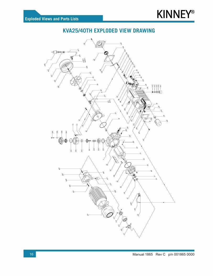
KVA25/40TH EXPLODED VIEW DRAWING
431
186
35
30
15
191
187
185
107
223
230
100
139
99
136
9695
138
8384
325
600
421
60
53
25
54
50
18
65
630
301
302
602
601
22
255
231
105
106
60
251
30
35
1
50
252
254
18
26
54
53
250
253
261
255
265
266
260
120
121
231
391
8975
321
340
88
471
145
156
474
221
221S
150
470
126
125
326
470S
-1
470S
-2
417
441
66
472
327
425
421
416
423
415
222
451
450
452
454S
453
455
456
455
78
31
31
90
451.
123
0
233
233S
311
312
313
316
317
159
17
05Exploded Views and Parts Lists
Manual 1865 Rev C p/n 001865 0000
KVA25/40TH PARTS LIST
ITEM NO. DESCRIPTION25
QTY40
QTY1 Cylinder 1 1
15 Rotor 1 1
18 Sleeve, Bearing 2 2
22 Vane 3 3
25 A-End Plate 1 1
26 B-End Plate 1 1
30 Bearing 2 2
35 Shaft Seal 2 2
47 Plug 1 1
50 O-Ring, End Plate 2 2
53 Hexagon Head Screw 6 6
54 Spring Lock Washer 6 6
60 Taper Pin 4 4
65 A-Shaft Key 1 1
66 B-Shaft Key 1 1
75 Oil Sump 1 1
79 Sheet Metal Baffl 1 1
83 Oil Sight Glass 1 1
84 Gasket, Oil Sight Glass 1 1
88 Plug, Oil Fill 1 1
89 O-Ring, Oil Fill Plug 1 1
95 Plug, Oil Drain 1 1
96 O-Ring, Oil Drain Plug 1 1
99 Theaded Fitting 1 1
100 Oil Filter 1 1
105 Oil Sump Cover Plate 1 1
106 Gasket, Oil Sump Cover 1 1
107 Allen Bolt 4 6
108 Sealing Ring 4 4
120 Exhaust Filter 1 1
121 O-Ring, Exhaust Filter 1 1
125 Filter Spring 1 1
126 Slotted Cheese Head Screw 1 1
136 Gasket, Service Cover 1 1
137 Sealing Ring 4 4
138 Allen Bolt 4 4
139 Service Cover 1 1
145 Exhaust Cover (w/ Threaded Flange) 1 1
150 Gasket, Exhaust Cover 1 1
155 Allen Bolt 4 4
156 Outlet Screen 1 1
159 Exhaust Valve Assembly 2 2
185 Gasket, Cylinder 1 1
186 Stud 4 4
187 Spring Lock Washer 4 4
191 Hexagon Nut 1 4
221 Bslm Hydraulic Fitting 1 1
221S Sealing Ring for 221 2 2
222 Straight Hydraulic Fitting 1 1
222S Sealing Ring for 222
223 Elbow Hydraulic Fitting 1 1
233 Bslm Hydraulic Fitting 1 1
230 Oil Tube (A) 1 1
231 Oil Tube (B) 1 1
233 BSLM Hydraulic Fitting 1 1
233S Sealing Ring for 233 2 2
251 Check Valve Plate 1 1
252 Check Valve Guide 1 1
253 O-Ring, Check Valve Plate 1 1
254 Check Valve Spring 1 1
250 Inlet Flange, Lower Housing 1 1
255 O-Ring, Inlet Part 2 2
260 Inlet Flange, Upper Housing 1 1
261 Inlet Screen 1 1
265 Allen Bolt 4 4
266 Spring Lock Washer 4 4
ITEM NO. DESCRIPTION25
QTY40
QTY285 Oil Recirculating Screw 1 1
286 Banjo Fitting 1 1
285S-1 Seal Ring for 285 1 1
285S-2 Sealing for 285 3 3
290 Oil Return Tube 1 1
291 Elbow Fitting 1 1
295S Sealing Ring for 295 2 2
295 Oil Return Valve 1 1
296 Banjo Fitting 1 1
297 Oil Return Tube 1 1
301 Allen Bolt 3 3
302 Spring Lock Washer 3 3
311 Coupling, Pump Side 1 1
312 Coupling Insert 1 1
313 Coupling, Motor Side 1 1
316 Set Screw (Pump Side) 2 2
317 Set Screw (Motor Side) 2 2
321 Fan, Pump Shaft End 1 1
325 Washer, Spring Lock 1 1
326 Washer, Plain 1 1
327 Hexagon Head Screw 1 1
340 Fan Hood 1 1
341 Hexagon Head Screw 3 3
391 Eye Bolt 1 1
415 Hexagon Nut 1 1
416 Slotted Set Screw 1 1
417 Slotted Set Screw 2 2
421 Rubber Foot 3 3
423 Spring Lock Washer 1 1
425 Washer 1 1
431 Directional Arrow Label 1 1
470 BSLM Hydraulic Fitting 1 1
470S-1 Sealing Ring for 470 1 1
470S-2 Sealing Ring for 470 1 1
471 Oil Tube 1 1
472 Non Return Valve 1 1
474 Air Filter 1 1
600 Motor (NEMA) (50Hz / 60Hz) 1 1
601 Hexagon Head Screw (NEMA) 1 1
602 Spring Lock Washer (NEMA) 4 4
613 Coupling, Motor Side (NEMA) 1 1
630 Motor Mounting Bracket (NEMA) 1 1
18
08Exploded Views and Parts Lists
Manual 1865 Rev C p/n 001865 0000
KVA63/100TH EXPLODED VIEW DRAWING
156
145
431
421
301
302
240
219
230
602
630
601
232
220
223
136
79
138
139
96
84
95
83
106
107
105
231
222s
121
120
126
89
75
391
88
125
50 1
311
613
312
186
35
30
15
191
187
185
310
60
53
25
54
50
18
65
22
255
1
50
252
254
251
18
261
250
265
266
260
1 3
232
233
233S
327
341
231
60
30
35
26
54
53
321
340
471
474
472*
*
470
47
470S
-147
0S-2
230
326
221
221S
417
441
440
600
100
99
66
325
425
421
416
423
415
222
451
450
452
454S
453
455
456
455
255
253
31
31
78
155
148
159
19
05Exploded Views and Parts Lists
Manual 1865 Rev C p/n 001865 0000
KVA63/100TH PARTS LISTITEM NO. DESCRIPTION
63 QTY
100 QTY
1 Cylinder 1 1
15 Rotor 1 1
18 Sleeve, Bearing 2 2
22 Vane 3 3
25 A-End Plate 1 1
26 B-End Plate 1 1
30 Bearing 2 2
35 Shaft Seal 2 2
42 Supporting Ring 2 2
43 Hexagon Head Screw 4 4
47 Plug 1 1
50 O-Ring, End Plate 2 2
53 Hexagon Head Screw 6 6
54 Spring Lock Washer 6 6
60 Taper Pin 4 4
63 Plug 1 1
65 A-Shaft Key 1 1
66 B-Shaft Key 1 1
75 Oil Sump 1 1
78 Steel Demister 1 1
79 Sheet Metal Baffl 1 1
83 Oil Sight Glass 1 1
84 Gasket, Oil Sight Glass 1 1
88 Plug, Oil Fill 1 1
89 O-Ring, Oil Fill Plug 1 1
95 Plug, Oil Drain 1 1
96 O-Ring, Oil Drain Plug 1 1
99 Theaded Fitting 1 1
100 Oil Filter 1 1
105 Oil Sump Cover Plate 1 1
106 Gasket, Oil Sump Cover 1 1
107 Allen Bolt 8 8
108 Sealing Ring 8 8
120 Exhaust Filter 2 2
121 O-Ring, Exhaust Filter 2 2
125 Filter Spring 2 2
126 Slotted Cheese Head Screw 2 2
136 Gasket, Service Cover 1 1
137 Sealing Ring 4 4
138 Allen Bolt 4 4
139 Service Cover 1 1
145 Exhaust Cover (Threaded Flange) 1 1
148 Exhaust Cover (Blocked) 1 1
150 Gasket, Exhaust Cover 2 2
155 Allen Bolt 8 8
156 Outlet Screen 1 1
159 Exhaust Valve Assembly 2 2
185 Gasket, Cylinder 1 1
186 Stud 4 4
187 Spring Lock Washer 4 4
191 Hexagon Nut 4 4
219 St Hydraulic Fit. KVA100 Only 0 1
220 St Hydraulic Fit. KVA100 Only 0 1
221 BSLM Hydraulic Fitting 1 1
221S Sealing Ring for 221 2 2
222 Straight Hydraulic Fitting 1 1
223 Elbow Hydraulic Fitting 1 0
230 Oil Tube (A) 1 1
231 Oil Tube (B) 1 1
232 A-Oil Tubing (B) (KVA100 Only) 0 1
233 BSLM Hydraulic Fitting 1 1
233S Sealing Ring for 233 2 2
ITEM NO. DESCRIPTION63
QTY100 QTY
240 Cooling Coil (KVA100 Only) + (219 + 220) 0 1
250 Inlet Flange, Lower Housing 1 1
251 Check Valve Plate 1 1
252 Check Valve Guide 1 1
253 O-Ring, Check Valve Plate 1 1
254 Check Valve Spring 1 1
255 O-Ring, Inlet Part 2 2
260 Inlet Flange, Upper Housing 1 1
261 Inlet Screen 1 1
265 Allen Bolt 4 4
266 Spring Lock Washer 4 4
301 Allen Bolt 3 3
302 Spring Lock Washer 3 3
311 Coupling, Pump Side 1 1
312 Coupling, Sleeve 1 1
316 Set Screw (Pump Side) 2 2
317 Set Screw (Motor Side) 2 2
321 Fan, Pump Shaft End 1 1
325 Washer, Spring Lock 1 1
326 Washer, Plain 1 1
327 Hexagon Bolt 1 1
340 Fan Hood 1 1
341 Hexagon Head Screw 3 3
391 Eye Bolt 1 1
415 Hexagon Nut 1 1
416 Slotted Set Screw 1 1
417 Slotted Set Screw 2 2
421 Rubber Foot 3 3
423 Spring Lock Washer 1 1
425 Washer 1 1
431 Directional Arrow Label 1 1
450 Float 1 1
451 Nozzle Assembly 1 1
452 Bolt 2 2
453 Bolt for Banjo Fitting, Oil Return 1 1
454S Sealing Ring for 454 2 2
455 Oil Return Tube with Banjo Fitting 1 1
456 Elbow Hydraulic Fitting 1 1
470 BSLM Hydraulic Fitting 1 1
470S-1 Sealing Ring for 470 1 1
470S-2 Sealing Ring for 470 1 1
471 Oil Tube (C) 1 1
472 Gas Ballast (Non Return Valve) 1 1
474 Air Filter 1 1
600 Motor (NEMA) (50Hz / 60Hz) 1 1
601 Hexagon Head Screw 4 4
602 Spring Lock Washer 4 4
613 Coupling, Motor Side 1 1
630 Motor Mounting Bracket (NEMA) 1 1
20
08Exploded Views and Parts Lists
Manual 1865 Rev C p/n 001865 0000
KVA160TH EXPLODED VIEW DRAWING
251
253
265
260
261
255
250
266
254
252
255
15
22
190
189
191
66
26
60
50
18
1
5018
53
54
321
390
391
393
392
185
340
341
477
473
474
221S
-1
221S
-2
53
54
25
402
622
401
610
602
601
431
600
421
417
230
221
314
456
455
231
223
232
421
418
300
240
219
219
303
302
427
426
326
325
327
65
221S
-1
221S
-222
1
314
320
3031
35
31
60
3030
1
35
441
44
2
443
613
317
312
311
316
126
125
8889
120
121
75
100
99
107
108
105
106
186
187
205
206
136
139
137
138
164
163
9695
8483
222s
.223
0
218
140
143
142
141
144
451
450
452
454S
454
146
145
455
208
415
416
421
425
207
451.
1
222
222s
.1
765
760
79
78
115
471
470
470S
-1
470S
-2
159
21
05Exploded Views and Parts Lists
Manual 1865 Rev C p/n 001865 0000
KVA160TH PARTS LISTITEM NO. DESCRIPTION QTY
1 Cylinder 115 Rotor 118 Sleeve, Bearing 422 Vane 325 A-End Plate 126 B-End Plate 130 Bearing 235 Shaft Seal 250 O-Ring, End Plate 253 Hexagon Head Screw 954 Spring Lock Washer 960 Taper Pin 465 A-Shaft Key 166 B-Shaft Key 175 Oil Sump 179 Sheet Metal Baffl 183 Oil Sight Glass 184 Gasket, Oil Sight Glass 188 Plug, Oil Fill 189 O-Ring, Oil Fill Plug 195 Plug, Oil Drain 196 O-Ring, Oil Drain Plug 199 Threaded Fitting 1
100 Oil Filter 1105 Oil Sump Cover Plate 1106 Gasket, Oil Sump Cover 1107 Allen Bolt 4108 Sealing Ring 4115 Filter Bracket 1120 Exhaust Filter 4121 O-Ring, Exhaust Filter 4125 Filter Spring 4126 Slotted Cheese Head Screw 4136 Gasket, Service Cover 1137 Sealing Ring 2138 Allen Bolt 2139 Service Cover (Tapped hole with 765) 1140 Allen Bolt 4141 Gasket, Separator Cover 1142 Separator Cover / Exhaust Cover 1143 Sealing Ring 4144 Perforated Metal Screen 1145 Strainer, Baffl 1146 Perforated Metal Screen 1159 Exhaust Valve Assembly 4163 Allen Bolt 2164 Sealing Ring 2168 O-Ring, Valve Cover Plate 1169 Valve Cover Plate 1176 Hex Nut 1177 Stud Bolt 1185 Gasket, Cylinder 1186 Allen Bolt 5187 Spring Lock Washer 5189 Stud 2190 Spring Lock Washer 2191 Hex Nut 2205 Side Cover Plate (Tapped hole with 760) 1206 Gasket, Side Cover Plate 1207 Allen Bolt 12208 Sealing Ring 12218 Socket 1219 Straight Hydraulic Fitting 2221 BSLM Hydraulic Fitting 2
221S.1 Sealing Ring for 221 2221S.2 Sealing Ring for 221 2
222 BSLM Hydraulic Fitting 1222S.1 Sealing Ring for 222 1222S.2 Sealing Ring for 222 1
223 Elbow Hydraulic Fitting 1230 Oil Tube (A) 1231 Oil Tube (B) 1232 Oil Tube (A-1) 1240 Cooling Spiral Coil 1
ITEM NO. DESCRIPTION QTY250 Inlet Flange, Lower Housing 1251 Check Valve Plate 1252 Check Valve Guide 1253 O-Ring, Check Valve Plate 1254 Check Valve Spring 1255 O-Ring, Inlet Part 2260 Inlet Flange, Upper Housing 1261 Inlet Screen (Conical) 1265 Allen Bolt 4266 Spring Lock Washer 4301 Stud 3302 Spring Lock Washer 3303 Hex Nut 3314 Hexagon Head Screw for Fan 10316 Set Screw (Pump Side) 2317 Set Screw (Motor Side) 2320 Spacer for Fan 1321 Pump Shaft End Fan 1325 Washer, Spring Lock 1326 Washer, Plain 1327 Hexagon Bolt 1340 Fan Hood 1341 Hexagon Head Screw 3390 Adapter for Eye Bolt 1391 Eye Bolt 1392 Spring Lock Washer 1393 Hexagon Head Screw 1401 Hexagon Head Screw 4402 Spring Lock Washer 4415 Hex Nut 1416 Slotted Set Screw 1417 Slotted Set Screw 1418 Slotted Set Screw 1421 Rubber Foot 3425 Washer 1426 Bracket for Rubber Foot 1427 Allen Bolt 2431 Directional Arrow Label 1432 Label Maintenance 1441 Protection Cover 1442 Hexagon Head Screw M6x12 2443 Washer, Spring Lock 2450 Float 1451 Nozzle Assembly 1
451.1 O-Ring for Nozzle Assy 1452 Bolt 2454 Hydraulic Fitting BSLM 1
454S Sealing Ring for 454 2455 Oil Return Tube 1456 Elbow Hydraulic Fitting 1470 BSLM Hydraulic Fitting 1
470S.1 Sealing Ring for 470 1470S.2 Sealing Ring for 470 1
471 Oil Tube (C) 1473 Fitting 1474 Gas Ballast Air Filter 1477 Ball Valve 1600 Motor (NEMA) 1601 Allen Bolt (NEMA) 4602 Spring Lock Washer (NEMA) 4610 Motor Mounting Flange (NEMA) 1613 Coupling Half, NEMA Motor Side 1622 Motor Shaft End Fan for NEMA Motor 1630 Motor Mounting Bracket (NEMA) 1760 Oil Temperature Switch (Optional) 1765 Oil Level Switch (Optional) 1
22
08Exploded Views and Parts Lists
Manual 1865 Rev C p/n 001865 0000
KVA250TH EXPLODED VIEW DRAWING
251
253
265
260
261
255
250
266
254
252
255 65
232
53
54
15
22
190
189
191
66
26
60
25
50
18
1
50
18
53
54
321
390
391
393
392
230
220
234
224
311
402
401
610
602
601
431
600
221S
-1
221S
-222
1
622
613
314
421
417
456
455
219
326
325
327
316
317
221S
-1
221S
-222
1
314
320
3031
35
31
60
3030
1
35
231
223
421
418
300
240
219
303
302
427
426
441
44
2
443
312
126
125
8889
115
120
121
75
100
99
107
108
105
106
186
187
205
206
136
139
137
138
164
163
9695
8483
222s
.223
0
218
140
143
142
141
144
451
450
452
454S
454
146
145
455
208
415
416
421
425
207
451.
1
222
222s
.1
765
760
79
78
345
341
242
359
243
241
360
477
473
474
471
470
470S
-1
470S
-2
185
159
23
05Exploded Views and Parts Lists
Manual 1865 Rev C p/n 001865 0000
KVA250TH PARTS LISTITEM NO. DESCRIPTION QTY
1 Cylinder 115 Rotor 118 Sleeve, Bearing 222 Vane 325 A-End Plate 126 B-End Plate 130 Bearing 235 Shaft Seal 247 Plug 150 O-Ring, End Plate 253 Hexagon Head Screw 954 Spring Lock Washer 960 Taper Pin 465 A-Shaft Key 166 B-Shaft Key 175 Oil Sump 179 Sheet Metal Baffl 183 Oil Sight Glass 184 Gasket, Oil Sight Glass 188 Plug, Oil Fill 189 O-Ring, Oil Fill Plug 195 Plug, Oil Drain 196 O-Ring, Oil Drain Plug 199 Threaded Fitting 1
100 Oil Filter 1105 Oil Sump Cover Plate 1106 Gasket, Oil Sump Cover 1107 Allen Bolt 4108 Sealing Ring for Oil Sump Pump 4115 Filter Bracket 1120 Exhaust Filter 4121 O-Ring, Exhaust Filter 4125 Filter Spring 4126 Slotted Cheese Head Screw 4136 Gasket, Service Cover 1137 Sealing Ring 2138 Allen Bolt 2139 Service Cover (Tapped hole with 765) 1140 Allen Bolt 4141 Gasket, Separator Cover 1142 Separator Cover Plate 1143 Sealing Ring 4144 Perforated Metal Screen 2145 Strainer, Baffl 1150 Gasket, Exhaust Cover 1152 Sealing Ring 4153 Exhaust Threaded Cover 1155 Allen Bolt 4156 Outlet Screen 1159 Exhaust Valve Assembly 4163 Allen Bolt 2164 Sealing Ring 2168 O-Ring, Valve Cover Plate 1169 Valve Cover Plate 1175 Plug 1176 Hex Nut 1177 Stud Bolt 1185 Gasket, Cylinder 1186 Allen Bolt 5187 Spring Lock Washer 5189 Stud 2190 Spring Lock Washer 2191 Hex Nut 2205 Side Cover Plate (Tapped hole with 760) 1206 Gasket, Side Cover Plate 1207 Allen Bolt 12220 Straight Hydraulic Fitting 2221 BSLM Hydraulic Fitting 1
221S-1 Sealing Ring for 221 1221S-2 Sealing Ring for 221 1
222 BSLM Hydraulic Fitting 1222S Sealing Ring 2230 Oil Tube 1231 Oil Tube 1232 Oil Tube 1234 Oil Tube (A-2) 1237 Blt Hydraulic Fitting 1241 Radiator 1242 Cover (Front), Radiator 1243 Cover (Rear), Radiator 1250 Inlet Flange, Lower Housing 1251 Check Valve Plate 1252 Check Valve Guide 1253 O-Ring, Check Valve Plate 1
ITEM NO. DESCRIPTION QTY254 Check Valve Spring 1255 O-Ring, Inlet Part 2260 Inlet Flange, Upper Housing 1261 Inlet Screen (Conical) 1265 Allen Bolt 4266 Spring Lock Washer 4300 Motor Mounting Bracket (NEMA) 1301 Stud 3302 Spring Lock Washer 3303 Hex Nut 3311 Coupling Half, Pump Side 1312 Connection Bolt with Rubber Boot 6314 Hexagon Head Screw for 50322B 5316 Set Screw (Pump Side) 2317 Set Screw (Motor Side) 2321 Pump Shaft End Fan 1341 Hexagon Head Screw 3345 Fan Cover 1359 Allen Bolt 4360 Allen Bolt 4390 Adapter for Eye Bolt 1391 Eye Bolt 1392 Spring Lock Washer 1393 Hexagon Head Screw 1401 Hexagon Head Screw 4402 Spring Lock Washer 4415 Hex Nut 1416 Slotted Set Screw 2417 Slotted Set Screw 1419 Sleeve 1421 Rubber Foot 3423 Spring Lock Washer 1425 Washer 1426 Bracket for Rubber Foot 1427 Allen Bolt 2431 Directional Arrow Label 1432 Label Maintenance 1441 Protection Cover 1442 Hexagon Head Screw M6x12 2443 Washer, Spring Lock 2450 Float 1451 Nozzle Assembly 1
451.1 O-Ring for Nozzle Assy 1452 Bolt 2454 Hydraulic Fitting BSLM 1
454S Sealing Ring for 454 2455 Oil Return Tube 1456 Elbow Hydraulic Fitting 1470 BSLM Hydraulic Fitting 1
470S.1 Sealing Ring for 470 1470S.2 Sealing Ring for 470 1
471 Oil Tube (C) 1473 Fitting 1474 Gas Ballast Air Filter 1477 Ball Valve 1600 Motor (NEMA) (50Hz / 60Hz) 1601 Allen Bolt (NEMA) 4602 Spring Lock Washer (NEMA) 4610 Motor Mounting Flange (NEMA) 1613 Coupling Half, Motor Side (NEMA) 1622 Motor Shaft End Fan for NEMA Motor 1760 Oil Temperature Switch (Optional) 1765 Oil Level Switch (Optional) 1
24
08Exploded Views and Parts Lists
Manual 1865 Rev C p/n 001865 0000
KVA400TH EXPLODED VIEW DRAWING
265
266
253
251
255
252
254
250
261
255
260
232
224
53
56
9
60
65
1
66
50
26
54
18
30
3532
0440
32132
7
328
353
351
354
236
359
360
329
224
53
60
226
22
50
54
54
35
18
30
47
4
421
417
9
357
358
355
239
238
356
358
357
230
225
232
231
474*
471*
470*
25
233
233
352
477*
224
15
231
630
600
302
303
421
417
619
420
431
5
258
473*
241
360
224S
-122
4S-2
226S
236S
224S
-122
4S-2
470S
-1*
470S
-2*
224S
-1
224S
-2
441
350
225S
602
601
610
603
168
78
187
79
186
177
176
169
108
100
99
230
225
107
75
105
136
139
137
138
164
207
206
208
8988
125
126
849695
83
163
116
117
391
225S
142
153
150
143
140
152
155
156
456S
106
144
145
760
765
425
421
416
423
415
205
115
450
451
456
452
451.
113
9
770
455
178
185
159
120
121 14
1
455
456,
456s
225.
1
225.
1
226.
1
236.
1
316
317
311
312
613
309
158
157
25
05Exploded Views and Parts Lists
Manual 1865 Rev C p/n 001865 0000
KVA400TH PARTS LISTITEM NO. DESCRIPTION QTY
1 Cylinder 14 Stud 45 Set Screw 69 Stud 615 Rotor 1
18-1 Sleeve, Bearing 218-2 Sleeve, Bearing 222 Vane 325 A-End Plate, Motor Side 126 B-End Plate, Fan Side 130 Bearing 235 Shaft Seal, Viton 446 Plug (for KVA Type) 147 Plug 150 O-Ring, End Plate 253 Hexagon Head Cap Screw 1054 Spring Lock Washer 1256 Hex Nut 260 Taper Pin 465 A-Shaft Key, Motor Side 166 B-Shaft Key, Fan Side 175 Oil Sump 179 Sheet Metal Baffl 183 Oil Sight Glass 184 Gasket, Oil Sight Glass 188 Plug, Oil Fill 189 O-Ring, Oil Fill Plug 195 Plug, Oil Drain 196 O-Ring, Oil Drain Plug 199 Pipe Nipple 1100 Oil Filter 1105 Oil Sump Cover Plate 1106 Gasket, Oil Sump Cover 1107 Allen Bolt 8108 Sealing Ring for Oil Sump Cover Plate 8115 Exhaust Filter Bracket, Upper 1116 Exhaust Filter Bracket, Medium 1117 Exhaust Filter Bracket, Lower 1120 Exhaust Filter 8121 O-Ring, Exhaust Filter 8125 Exhaust Filter Spring Assembly 8126 Slotted Cheese Head Machine Screw 8136 Gasket, Service Cover 1137 Sealing Ring 2138 Allen Bolt 2139 Service Cover (Tapped hole with 765) 1140 Allen Bolt 8141 Gasket, Separator Cover 1142 Separator Cover Plate 1143 Sealing Ring 8144 Perforated Metal Screen 2145 Strainer, Baffl 1150 Gasket, Exhaust Cover 1152 Sealing Ring 4153 Exhaust Cover (Threaded) 1155 Allen Bolt 4156 Outlet Screen 1159 Exhaust Valve Assembly 7163 Allen Bolt 2164 Sealing Ring 2168 O-Ring, Exhaust Valve Cover Plate 1169 Exhaust Valve Cover Plate 1175 Plug 1176 Hex Nut 1177 Stud Bolt 1185 Gasket, Cylinder 1186 Allen Bolt 8187 Spring Lock Washer 8205 Oil Sump Side Cover Plate (Tapped hole with 760) 1206 Gasket, Oil Sump Side Cover Plate 1207 Allen Bolt (Socket Head Cap Screw) 9208 Sealing Ring 9224 BSLM, Hydraulic Fitting 4
224S-1 Sealing Ring for 224 4224S-2 Sealing Ring for 224 4
225 BSLM, Hydraulic Fitting 2225S Sealing Ring for 225 2226 BSLM, Hydraulic Fitting 1
226S Sealing Ring for 226 2230 Oil Tube (A) 1231 Oil Tube (B-1) 1232 Oil Tube (B-2) 1
ITEM NO. DESCRIPTION QTY233 Oil Tube 1236 BSLM, Hydraulic Fitting 1
236S Sealing Ring 1238 Hex Nut 1239 Spring Lock Washer 1241 Oil Cooler 1250 Inlet Flange, Lower Housing 1251 Check Valve Plate 1252 Check Valve Guide 1253 O-Ring, Check Valve Plate 1254 Spring, Check Valve 1255 O-Ring, Inlet Flange 2258 Rubber Ball 1260 Inlet Flange, Upper Housing 1261 Inlet Screen (Conical) 1265 Allen Bolt 3266 Spring Lock Washer 3285 Oil Recirculating Screw 1286 BSLM Hydraulic Fitting 1
285S-1 Sealing Ring for 285 1285S-2 Sealing Ring for 285 1
290 Oil Return Tube 1291 BSLM Hydraulic Fitting 1
291S Sealing Ring, for 291 2302 Spring Lock Washer 4303 Hex Nut 4311 Coupling Half, Pump Side 1312 Connection Bolt with Rubber Boot 8316 Set Screw (Pump Side) 2317 Set Screw (Motor Side) 2320 Spacer for Fan 1321 Fan 1327 Locking Disc 1328 Hex Head Cap Screw 1329 Spring Lock Washer 1350 Fan Support Ring (Pump Side) 1351 Fan Support Ring (Radiator Side) 1352 Fan Guard 1353 Allen Bolt 4354 Hex Nut 4355 Fan Supporting Bolt 5356 Fan Supporting Bolt 1357 Hex Nut 11358 Spring Lock Washer 11359 Mounting Bracket for Radiator 1360 Cheese Head Cap Screw 12391 Eye Bolt 1415 Hex Nut 2416 Stud 2417 Slotted Set Screw 2420 Slotted Set Screw 1421 Rubber Foot 5423 Spring Lock Washer 2425 Washer 2431 Directional Arrow Label 1600 Motor (NEMA) (50Hz / 60Hz) 1601 Hex Head Bolt 3602 Spring Lock Washer 3603 Allen Bolt 4610 Motor Mounting Flange Adapter (NEMA) 1613 Coupling Half, Motor Side 1619 Spacer for Foot, for NEMA Motor 2630 Motor Mounting Bracket 1760 Oil Temperature Switch (Optional) 1765 Oil Level Switch (Optional) 1770 Oil Heater (Optional) 1

26
08Exploded Views and Parts Lists
Manual 1865 Rev C p/n 001865 0000
KVA630TH EXPLODED VIEW DRAWING
265
266
253
251
255
252
254
250
261
255
260
232
224
53
56
9
60
65
1
66
26
54
18
30
3532
0440
32132
7
328
353
351
354
236
359
360
329
224
53
60
226
22
50
54
54
316
35
18
30
47
4
421
417
9
357
358
355
239
238
356
358
357
230
225
232
231
474
471
470
25
233
233
352
477
224
15
231
401
317
630
311
402
600
302
303
421
417
619
420
431
5
258
473
241
224S
-122
4S-2
226S
236S
224S
-122
4S-2
470S
-147
0S-2
224S
-1
224S
-2
441
312
350
225S
613
(601
)(6
02)
50
185
159
455
456,
456s
168
78
187
79
186
177
176
169
108
100
99
230
225
107
75
105
136
139
137
138
164
207
206
208
120
8988
125
121
126
849695
83
163
116
117
391
225S
142
141
153
150
143
140
152
155
156
456S
106
144
145
760
765
425
421
416
423
415
205
115
158
450
451
456
452
451.
113
9
770
455
157
178
225.
1
225.
1
226.
1
236.
1
309
27
05Exploded Views and Parts Lists
Manual 1865 Rev C p/n 001865 0000
KVA630TH PARTS LISTITEM NO. DESCRIPTION QTY
1 Cylinder 14 Stud 45 Set Screw 69 Stud 615 Rotor 1
18-1 Sleeve, Bearing 218-2 Sleeve, Bearing 222 Vane 325 A-End Plate, Motor Side 126 B-End Plate, Fan Side 130 Bearing 235 Shaft Seal, Viton 446 Plug (for KVA Type) 147 Plug 150 O-Ring, End Plate 253 Hexagon Head Cap Screw 1054 Spring Lock Washer 1256 Hex Nut 260 Taper Pin 465 A-Shaft Key, Motor Side 166 B-Shaft Key, Fan Side 175 Oil Sump 179 Sheet Metal Baffl 183 Oil Sight Glass 184 Gasket, Oil Sight Glass 188 Plug, Oil Fill 189 O-Ring, Oil Fill Plug 195 Plug, Oil Drain 196 O-Ring, Oil Drain Plug 199 Pipe Nipple 1100 Oil Filter 1105 Oil Sump Cover Plate 1106 Gasket, Oil Sump Cover 1107 Allen Bolt 8108 Sealing Ring for Oil Sump Cover Plate 8115 Exhaust Filter Bracket, Upper 1116 Exhaust Filter Bracket, Medium 1117 Exhaust Filter Bracket, Lower 1120 Exhaust Filter 8121 O-Ring, Exhaust Filter 8125 Exhaust Filter Spring Assembly 8126 Slotted Cheese Head Machine Screw 8136 Gasket, Service Cover 1137 Sealing Ring 2138 Allen Bolt 2139 Service Cover (Tapped hole with 765) 1140 Allen Bolt 8141 Gasket, Separator Cover 1142 Separator Cover Plate 1143 Sealing Ring 8144 Perforated Metal Screen 2145 Strainer, Baffl 1150 Gasket, Exhaust Cover 1152 Sealing Ring 4153 Exhaust Cover (Threaded) 1155 Allen Bolt 4156 Outlet Screen 1159 Exhaust Valve Assembly 7163 Allen Bolt 2164 Sealing Ring 2168 O-Ring, Exhaust Valve Cover Plate 1169 Exhaust Valve Cover Plate 1175 Plug 1176 Hex Nut 1177 Stud Bolt 1185 Gasket, Cylinder 1186 Allen Bolt 8187 Spring Lock Washer 8205 Oil Sump Side Cover Plate (Tapped hole with 760) 1206 Gasket, Oil Sump Side Cover Plate 1207 Allen Bolt (Socket Head Cap Screw) 9208 Sealing Ring 9224 BSLM, Hydraulic Fitting 4
224S-1 Sealing Ring for 224 4224S-2 Sealing Ring for 224 4
225 BSLM, Hydraulic Fitting 2225S Sealing Ring for 225 2226 BSLM, Hydraulic Fitting 1
226S Sealing Ring for 226 2230 Oil Tube (A) 1231 Oil Tube (B-1) 1232 Oil Tube (B-2) 1
ITEM NO. DESCRIPTION QTY233 Oil Tube 1236 BSLM, Hydraulic Fitting 1
236S Sealing Ring 1238 Hex Nut 1239 Spring Lock Washer 1241 Oil Cooler 1250 Inlet Flange, Lower Housing 1251 Check Valve Plate 1252 Check Valve Guide 1253 O-Ring, Check Valve Plate 1254 Spring, Check Valve 1255 O-Ring, Inlet Flange 2258 Rubber Ball 1260 Inlet Flange, Upper Housing 1261 Inlet Screen (Conical) 1265 Allen Bolt 3266 Spring Lock Washer 3285 Oil Recirculating Screw 1286 BSLM Hydraulic Fitting 1
285S-1 Sealing Ring for 285 1285S-2 Sealing Ring for 285 1
290 Oil Return Tube 1291 BSLM Hydraulic Fitting 1
291S Sealing Ring, for 291 2302 Spring Lock Washer 4303 Hex Nut 4311 Coupling Half, Pump Side 1312 Connection Bolt with Rubber Boot 8316 Set Screw (Pump Side) 2317 Set Screw (Motor Side) 2320 Spacer for Fan 1321 Fan 1327 Locking Disc 1328 Hex Head Cap Screw 1329 Spring Lock Washer 1350 Fan Support Ring (Pump Side) 1351 Fan Support Ring (Radiator Side) 1352 Fan Guard 1353 Allen Bolt 4354 Hex Nut 4355 Fan Supporting Bolt 5356 Fan Supporting Bolt 1357 Hex Nut 11358 Spring Lock Washer 11359 Mounting Bracket for Radiator 1360 Cheese Head Cap Screw 12391 Eye Bolt 1401 Hexagon Head Screw 4402 Spring Lock Washer 4415 Hex Nut 2416 Stud 2417 Slotted Set Screw 2420 Slotted Set Screw 1421 Rubber Foot 5423 Spring Lock Washer 2425 Washer 2600 Motor (NEMA) (50Hz / 60Hz) 1601 Hex Head Bolt 3602 Spring Lock Washer 3603 Allen Bolt 4610 Motor Mounting Flange Adapter (NEMA) 1613 Coupling Half, Motor Side 1619 Spacer for Foot, for NEMA Motor 2630 Motor Mounting Bracket 1760 Oil Temperature Switch (Optional) 1765 Oil Level Switch (Optional) 1770 Oil Heater (Optional) 1
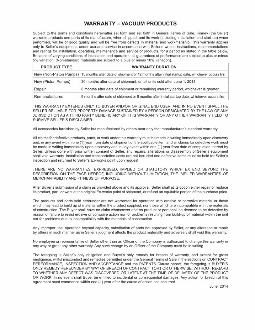
WARRANTY – VACUUM PRODUCTSSubject to the terms and conditions hereinafter set forth and set forth in General Terms of Sale, Kinney (the Seller) warrants products and parts of its manufacture, when shipped, and its work (including installation and start-up) when performed, will be of good quality and will be free from defects in material and workmanship. This warranty applies only to Seller’s equipment, under use and service in accordance with Seller’s written instructions, recommendations and ratings for installation, operating, maintenance and service of products, for a period as stated in the table below. Because of varying conditions of installation and operation, all guarantees of performance are subject to plus or minus 5% variation. (Non-standard materials are subject to a plus or minus 10% variation).
PRODUCT TYPE WARRANTY DURATION
New (Non-Piston Pumps) 15 months after date of shipment or 12 months after initial startup date, whichever occurs firs
New (Piston Pumps) 30 months after date of shipment, on all units sold after June 1, 2014.
Repair 6 months after date of shipment or remaining warranty period, whichever is greater
Remanufactured 9 months after date of shipment or 6 months after initial startup date, whichever occurs firs
THIS WARRANTY EXTENDS ONLY TO BUYER AND/OR ORIGINAL END USER, AND IN NO EVENT SHALL THE SELLER BE LIABLE FOR PROPERTY DAMAGE SUSTAINED BY A PERSON DESIGNATED BY THE LAW OF ANY JURISDICTION AS A THIRD PARTY BENEFICIARY OF THIS WARRANTY OR ANY OTHER WARRANTY HELD TO SURVIVE SELLER’S DISCLAIMER. All accessories furnished by Seller but manufactured by others bear only that manufacturer’s standard warranty.
All claims for defective products, parts, or work under this warranty must be made in writing immediately upon discovery and, in any event within one (1) year from date of shipment of the applicable item and all claims for defective work must be made in writing immediately upon discovery and in any event within one (1) year from date of completion thereof by Seller. Unless done with prior written consent of Seller, any repairs, alterations or disassembly of Seller’s equipment shall void warranty. Installation and transportation costs are not included and defective items must be held for Seller’s inspection and returned to Seller’s Ex-works point upon request.
THERE ARE NO WARRANTIES, EXPRESSED, IMPLIED OR STATUTORY WHICH EXTEND BEYOND THE DESCRIPTION ON THE FACE HEREOF, INCLUDING WITHOUT LIMITATION, THE IMPLIED WARRANTIES OF MERCHANTABILITY AND FITNESS OF PURPOSE.
After Buyer’s submission of a claim as provided above and its approval, Seller shall at its option either repair or replace its product, part, or work at the original Ex-works point of shipment, or refund an equitable portion of the purchase price.
The products and parts sold hereunder are not warranted for operation with erosive or corrosive material or those which may lead to build up of material within the product supplied, nor those which are incompatible with the materials of construction. The Buyer shall have no claim whatsoever and no product or part shall be deemed to be defective by reason of failure to resist erosive or corrosive action nor for problems resulting from build-up of material within the unit nor for problems due to incompatibility with the materials of construction.
Any improper use, operation beyond capacity, substitution of parts not approved by Seller, or any alteration or repair by others in such manner as in Seller’s judgment affects the product materially and adversely shall void this warranty.
No employee or representative of Seller other than an Officer of the Company is authorized to change this warranty in any way or grant any other warranty. Any such change by an Officer of the Company must be in writing.
The foregoing is Seller’s only obligation and Buyer’s only remedy for breach of warranty, and except for gross negligence, willful misconduct and remedies permitted under the General Terms of Sale in the sections on CONTRACT PERFORMANCE, INSPECTION AND ACCEPTANCE and the PATENTS Clause hereof, the foregoing is BUYER’S ONLY REMEDY HEREUNDER BY WAY OF BREACH OF CONTRACT, TORT OR OTHERWISE, WITHOUT REGARD TO WHETHER ANY DEFECT WAS DISCOVERED OR LATENT AT THE TIME OF DELIVERY OF THE PRODUCT OR WORK. In no event shall Buyer be entitled to incidental or consequential damages. Any action for breach of this agreement must commence within one (1) year after the cause of action has occurred.
June, 2014
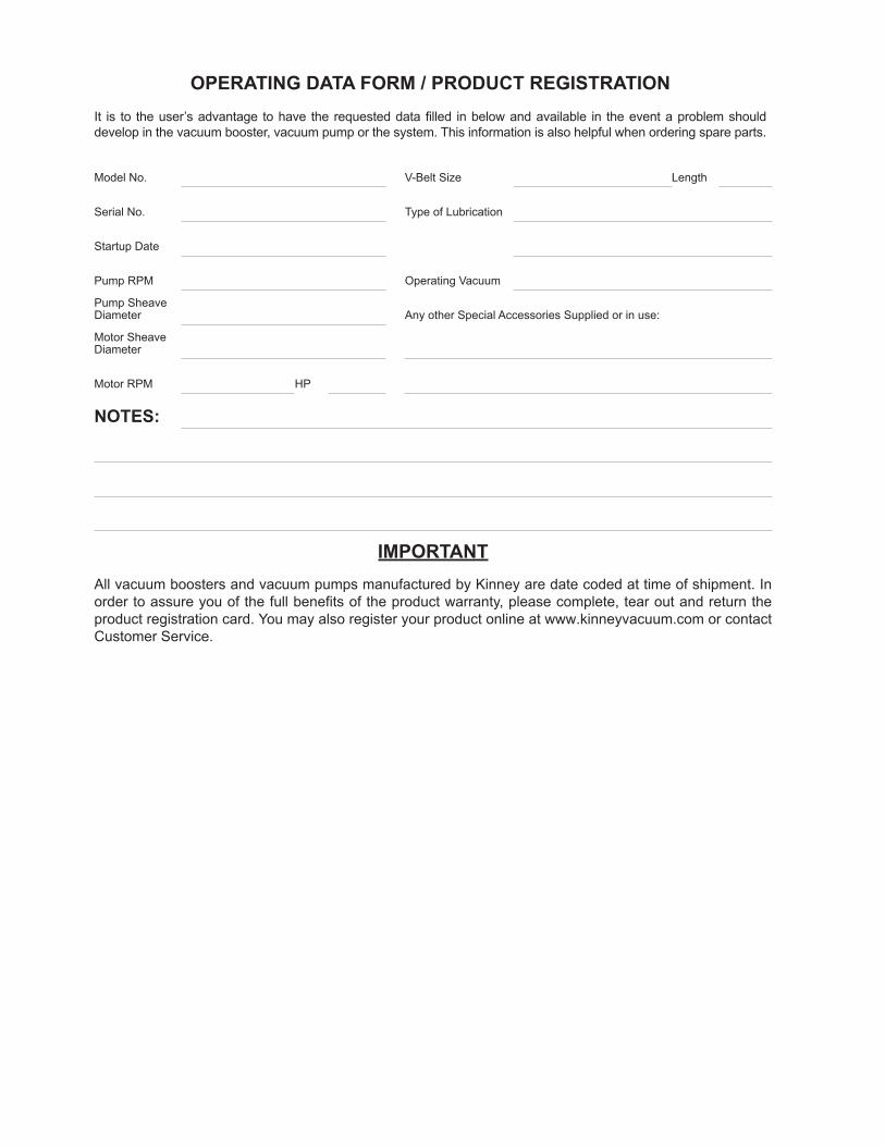
IMPORTANTAll vacuum boosters and vacuum pumps manufactured by Kinney are date coded at time of shipment. In order to assure you of the full benefits of the product warranty, please complete, tear out and return the product registration card. You may also register your product online at www.kinneyvacuum.com or contact Customer Service.
OPERATING DATA FORM / PRODUCT REGISTRATIONIt is to the user’s advantage to have the requested data filled in below and available in the event a problem should develop in the vacuum booster, vacuum pump or the system. This information is also helpful when ordering spare parts.
Model No. V-Belt Size Length
Serial No. Type of Lubrication
Startup Date
Pump RPM Operating Vacuum
Pump SheaveDiameter Any other Special Accessories Supplied or in use:
Motor SheaveDiameter
Motor RPM HP
NOTES:

Page Intentionally Blank

Page Intentionally Blank
Manual 1865 Rev C p/n 001865 000004/21
For Service & Repair, Technical Support, or Product Sales contact:
Kinney4840 West Kearney Street Springfield, Missouri USA 5803-8702 O 417.865.8715 800.825.6937 F 417.865.2950www.kinneyvacuum.com