Embed Size (px)
Citation preview
Helios VentilatorenMONTAGE- UND BETRIEBSVORSCHRIFT
INSTALLATION AND OPERATING INSTRUCTIONS
NOTICE DE MONTAGE ET D’UTILISATION
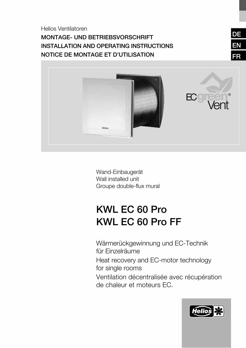
Wand-Einbaugerät Wall installed unit Groupe double-flux mural
KWL EC 60 ProKWL EC 60 Pro FF
Wärmerückgewinnung und EC-Technik für EinzelräumeHeat recovery and EC-motor technology for single roomsVentilation décentralisée avec récupération de chaleur et moteurs EC.
DE
EN
FR
Helios VentilatorenMONTAGE- UND BETRIEBSVORSCHRIFT
Inhaltsverzeichnis
KAPITEL 1 ALLGEMEINE MONTAGE- UND BETRIEBSHINWEISE . . . . . . . . . . . . . . . . . . . . . . . . . . . . . . . . . . . Seite 11.0 Wichtige Informationen . . . . . . . . . . . . . . . . . . . . . . . . . . . . . . . . . . . . . . . . . . . . . . . . . . . . . . . . . . . . . . . . . Seite 11.1 Warn- und Sicherheitshinweise . . . . . . . . . . . . . . . . . . . . . . . . . . . . . . . . . . . . . . . . . . . . . . . . . . . . . . . . . . . Seite 11.2 Garantieansprüche – Haftungsausschluss . . . . . . . . . . . . . . . . . . . . . . . . . . . . . . . . . . . . . . . . . . . . . . . . . . . Seite 11.3 Vorschriften – Richtlinien . . . . . . . . . . . . . . . . . . . . . . . . . . . . . . . . . . . . . . . . . . . . . . . . . . . . . . . . . . . . . . . . Seite 11.4 Sendungsannahme . . . . . . . . . . . . . . . . . . . . . . . . . . . . . . . . . . . . . . . . . . . . . . . . . . . . . . . . . . . . . . . . . . . . Seite 11.5 Einlagerung . . . . . . . . . . . . . . . . . . . . . . . . . . . . . . . . . . . . . . . . . . . . . . . . . . . . . . . . . . . . . . . . . . . . . . . . . . Seite 11.6 Einsatzbereich – Anwendung . . . . . . . . . . . . . . . . . . . . . . . . . . . . . . . . . . . . . . . . . . . . . . . . . . . . . . . . . . . . Seite 11.7 Wirkungsweise . . . . . . . . . . . . . . . . . . . . . . . . . . . . . . . . . . . . . . . . . . . . . . . . . . . . . . . . . . . . . . . . . . . . . . . Seite 11.8 Leistungsdaten . . . . . . . . . . . . . . . . . . . . . . . . . . . . . . . . . . . . . . . . . . . . . . . . . . . . . . . . . . . . . . . . . . . . . . . Seite 11.9 Feuerstätten . . . . . . . . . . . . . . . . . . . . . . . . . . . . . . . . . . . . . . . . . . . . . . . . . . . . . . . . . . . . . . . . . . . . . . . . . Seite 11.10 Elektrischer Anschluss. . . . . . . . . . . . . . . . . . . . . . . . . . . . . . . . . . . . . . . . . . . . . . . . . . . . . . . . . . . . . . . . . . Seite 21.11 Technische Daten . . . . . . . . . . . . . . . . . . . . . . . . . . . . . . . . . . . . . . . . . . . . . . . . . . . . . . . . . . . . . . . . . . . . . Seite 21.12 Zubehör . . . . . . . . . . . . . . . . . . . . . . . . . . . . . . . . . . . . . . . . . . . . . . . . . . . . . . . . . . . . . . . . . . . . . . . . . . . . Seite 2
KAPITEL 2 LIEFERWEISE / BESTELLUMFANG . . . . . . . . . . . . . . . . . . . . . . . . . . . . . . . . . . . . . . . . . . . . . . . . . . Seite 22.0 Lieferweise / Bestellumfang . . . . . . . . . . . . . . . . . . . . . . . . . . . . . . . . . . . . . . . . . . . . . . . . . . . . . . . . . . . . . . Seite 2
KAPITEL 3 MONTAGE/AUFSTELLUNG . . . . . . . . . . . . . . . . . . . . . . . . . . . . . . . . . . . . . . . . . . . . . . . . . . . . . . . . . Seite 33.0 Wandmontage KWL 60 RS Rohbauset . . . . . . . . . . . . . . . . . . . . . . . . . . . . . . . . . . . . . . . . . . . . . . . . . . . . . Seite 33.1 Steuer- und Netzzuleitung verlegen . . . . . . . . . . . . . . . . . . . . . . . . . . . . . . . . . . . . . . . . . . . . . . . . . . . . . . . . Seite 33.2 Montage KWL EC 60 Pro... Lüftungseinsatz . . . . . . . . . . . . . . . . . . . . . . . . . . . . . . . . . . . . . . . . . . . . . . . . . Seite 33.3 Montage KWL 60 WV Wandhülsenverlängerung . . . . . . . . . . . . . . . . . . . . . . . . . . . . . . . . . . . . . . . . . . . . . . Seite 33.4 Montage KWL 60 DR Distanzrahmen . . . . . . . . . . . . . . . . . . . . . . . . . . . . . . . . . . . . . . . . . . . . . . . . . . . . . . Seite 4
KAPITEL 4 BEDIENELEMENT KWL-BCU/KWL-BCA . . . . . . . . . . . . . . . . . . . . . . . . . . . . . . . . . . . . . . . . . . . . . . Seite 44.0 Funktionsbeschreibung Menübaum. . . . . . . . . . . . . . . . . . . . . . . . . . . . . . . . . . . . . . . . . . . . . . . . . . . . . . . . Seite 44.1 Bedienelement KWL 60 BC.. . . . . . . . . . . . . . . . . . . . . . . . . . . . . . . . . . . . . . . . . . . . . . . . . . . . . . . . . . . . . . Seite 64.2 Bedienmenü . . . . . . . . . . . . . . . . . . . . . . . . . . . . . . . . . . . . . . . . . . . . . . . . . . . . . . . . . . . . . . . . . . . . . . . . . Seite 64.3 Fehlermenü/Fehleranzeige im Display . . . . . . . . . . . . . . . . . . . . . . . . . . . . . . . . . . . . . . . . . . . . . . . . . . . . . Seite 124.4 Tabelle: Wochenprogramm . . . . . . . . . . . . . . . . . . . . . . . . . . . . . . . . . . . . . . . . . . . . . . . . . . . . . . . . . . . . . Seite 12
KAPITEL 5 ELEKTROANSCHLUSS . . . . . . . . . . . . . . . . . . . . . . . . . . . . . . . . . . . . . . . . . . . . . . . . . . . . . . . . . . . Seite 135.0 Elektrischer Anschluss. . . . . . . . . . . . . . . . . . . . . . . . . . . . . . . . . . . . . . . . . . . . . . . . . . . . . . . . . . . . . . . . . Seite 135.1 Schaltplan SS-950 . . . . . . . . . . . . . . . . . . . . . . . . . . . . . . . . . . . . . . . . . . . . . . . . . . . . . . . . . . . . . . . . . . . Seite 13 5.2 Schaltplan SS-958 . . . . . . . . . . . . . . . . . . . . . . . . . . . . . . . . . . . . . . . . . . . . . . . . . . . . . . . . . . . . . . . . . . . Seite 14
KAPITEL 6 REINIGUNG UND WARTUNG . . . . . . . . . . . . . . . . . . . . . . . . . . . . . . . . . . . . . . . . . . . . . . . . . . . . . . Seite 156.0 Kondensatableitung . . . . . . . . . . . . . . . . . . . . . . . . . . . . . . . . . . . . . . . . . . . . . . . . . . . . . . . . . . . . . . . . . . Seite 156.1 Filterwechsel . . . . . . . . . . . . . . . . . . . . . . . . . . . . . . . . . . . . . . . . . . . . . . . . . . . . . . . . . . . . . . . . . . . . . . . . Seite 156.2 Reinigung – Wartung . . . . . . . . . . . . . . . . . . . . . . . . . . . . . . . . . . . . . . . . . . . . . . . . . . . . . . . . . . . . . . . . . . Seite 15
Korrekte Entsorgung dieses Produktes (Elektromüll)Die Kennzeichnung auf dem Produkt bzw. auf der dazugehörigen Montage- und Betriebsvorschrift gibt an, dass es nach seiner Lebensdauer nicht zusammen mit dem normalen Haushaltsmüll entsorgt werden darf. Entsorgen Sie dieses Gerät bitte getrennt von anderen Abfällen, um der Umwelt bzw. der menschlichen Gesund-heit nicht durch unkontrollierte Müllbeseitigung zu schaden. Recyceln Sie das Gerät, um die nachhaltige Wiederverwertung von stofflichen Ressourcen zu fördern.Private Nutzer sollten den Händler, bei dem das Produkt gekauft wurde, oder die zuständigen Behörden kontaktieren, um in Erfahrung zu bringen, wie sie das Gerät auf umweltfreundliche Weise recyceln können.Gewerbliche Nutzer sollten sich an Ihren Lieferanten wenden und die Bedingungen des Verkaufsvertrags konsultieren. Dieses Produkt darf nicht zusammen mit ande-rem Gewerbemüll entsorgt werden.
DEUTSCH
TIPP!
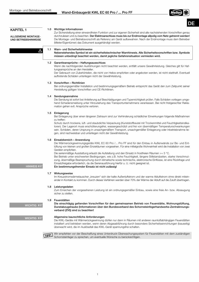
1 .0 Wichtige InformationenZur Sicherstellung einer einwandfreien Funktion und zur eigenen Sicherheit sind alle nachstehenden Vorschriften genau durchzulesen und zu beachten. Der Elektroanschluss muss bis zur Endmontage allpolig vom Netz getrennt werden! Die Montage- und Betriebsvorschrift als Referenz am Gerät aufbewahren. Nach der Endmontage muss dem Betreiber (Mieter/Eigentümer) das Dokument ausgehändigt werden.
1 .1 Warn- und Sicherheitshinweise Nebenstehendes Symbol ist ein sicherheitstechnischer Warnhinweis . Alle Sicherheitsvorschriften bzw . Symbole müssen unbedingt beachtet werden, damit jegliche Gefahrensituation vermieden wird .
1 .2 Garantieansprüche – HaftungsausschlussWenn die nachfolgenden Ausführungen nicht beachtet werden, entfällt unsere Gewährleistung. Gleiches gilt für Haf-tungsansprüche an den Hersteller.Der Gebrauch von Zubehörteilen, die nicht von Helios empfohlen oder angeboten werden, ist nicht statthaft. Even tuell auftretende Schäden unterliegen nicht der Gewährleistung.
1 .3 Vorschriften – RichtlinienBei ordnungsgemäßer Installation und bestimmungsgemäßem Betrieb entspricht das Gerät den zum Zeit punkt seiner Herstellung gültigen Vorschriften und CE-Richtlinien.
1 .4 SendungsannahmeDie Sendung ist sofort bei Anlieferung auf Beschädi gungen und Typenrichtigkeit prüfen. Falls Schäden vorliegen umge-hend Schadensmeldung unter Hinzuziehung des Transportunternehmens veranlassen. Bei nicht fristgerechter Rekla-mation gehen evtl. Ansprüche verloren.
1 .5 EinlagerungBei Einlagerung über einen längeren Zeitraum sind zur Verhinderung schädlicher Einwirkungen folgende Maßnahmen zu treffen:Schutz durch trockene, luft- und staubdichte Verpackung (Kunststoffbeutel mit Trockenmittel und Feuchtigkeitsindika-toren). Der Lagerort muss erschütterungsfrei, wassergeschützt und frei von übermäßigen Temperaturschwankungen sein. Schäden, deren Ursprung in unsachgemäßem Transport, unsachgemäßer Einlagerung oder Inbetriebnahme lie-gen, sind nachweisbar und unterliegen nicht der Gewährleistung.
1 .6 Einsatzbereich – AnwendungDie Wärmerückgewinnungsgeräte KWL EC 60 Pro /... Pro FF sind für den Einbau in Außenwände zur Be- und Ent-lüftung von kleinen und großen Einzelräumen vorgesehen. Für eine mittelgroße Wohneinheit wird die Installation von zwei Geräten empfohlen.Die serienmäßige Ausstattung erlaubt die Aufstellung und den Einsatz in frostfreien Räumen >+ 5 °C. Bei Betrieb unter erschwerten Bedingungen, wie z.B. hohe Feuchtigkeit, längere Stillstandzeiten, starke Verschmut-zung, übermäßige Beanspruchung durch klimatische sowie technische, elektronische Einflüsse, ist eine Rückfrage und Einsatzfreigabe erforderlich, da die Serienausführung hierfür u. U. nicht geeignet ist. Ein bestimmungsfremder Einsatz ist nicht zu lässig!
1 .7 WirkungsweiseIm Kreuzstromwärmetauscher „kreuzen“ sich der kalte Außenluftstrom und der warme Abluftstrom ohne direkt mitein-ander in Kontakt zu kommen. Durch dieses Verfahren werden über 70% der Wärme der Abluft auf die Zuluft übertragen.
1 .8 LeistungsdatenZum Erreichen der vorgesehenen Leistung ist ein ordnungsgemäßer Einbau, sowie eine freie An- bzw. Absaugung sicher zu stellen.
1 .9 Feuerstätten Die einschlägig geltenden Vorschriften für den gemeinsamen Betrieb von Feuerstätte, Wohnungslüftung, Dunstabzugshaube (Informationen über den Bundesverband des Schornsteinfegerhandwerks-Zentralinnungs-verband (ZVI)) sind zu beachten!
Allgemeine baurechtliche AnforderungenDie KWL-Geräte mit Wärmerückgewinnung dürfen nur dann in Räumen mit anderen raumluftabhängigen Feuerstätten installiert und betrieben werden, wenn deren Abgasabführung durch besondere Sicherheitseinrichtungen (bauseitig) überwacht wird, die im Auslösefall das KWL-Gerät spannungsfrei schalten.
Wir empfehlen vor der Beschaffung eines Unterdruck-Überwachungssystem für Feuerstätten mit dem zuständigen Schornsteinfeger zu sprechen, um eventuelle Wünsche zu berücksichtigen.
1
Wand-Einbaugerät KWL EC 60 Pro / . . . Pro FFMontage- und Betriebsvorschrift
KAPITEL 1
ALLGEMEINE MONTAGE- UND BETRIEBSHINWEISE
m
HINWEIS +
DE
WICHTIG +
WICHTIG +
1 .10 Elektrischer AnschlussVor allen Wartungs- und Installationsarbeiten oder vor Öffnen des Schaltraumes ist das Gerät allpolig vom Netz zu trennen! Der elektrische Anschluss darf nur von einer autorisierten Elektrofachkraft entsprechend den nachstehenden Anschlussplänen ausgeführt werden . Der Elektroanschluss muss bis zur Endmontage allpolig vom Netz getrennt werden! Die einschlägigen Normen, Sicherheitsbestimmungen (z.B. DIN VDE 0100) sowie die TAB der EVUs sind unbedingt zu beachten. Ein allpoliger Netztrennschalter / Revisionsschalter, mit mindestens 3 mm Kontaktöffnung (VDE 0700 T1 7.12.2 / EN 60335-1) ist zwingend vorgeschrieben. Das Bedienelement KWL 60 BC.. wird mittels Steuerleitung mit dem Lüftungseinsatz des Gerätes verbunden. Die Netzleitung (flexible Leitung) wird an der Steckerbuchse angeschlossen (siehe Seite 4, Schaltplan SS-950 bzw. SS-958).
1 .11 Technische DatenSpannung/Frequenz 230 V~/50 Hz Netz-Zuleitung über flexible Leitung 2 x 1,5 mm2
Nennstrom A 0,06 Anschluss nach Schaltplan SS-950Schutzart IPX4 Temperatur Arbeitsbereich -20 °C bis 40 °CSchutzklasse II Gewicht Rohbauset 3,25 kgElektrische Zuleitung bis UV NYM-J 3 x 1,5 mm2 Gewicht Lüftungseinsatz 5,55 kg
1 .12 Zubehör KWL 60 WV Best.-Nr. 0884 Wandhülsen-Verlängerung für Wandstärken über 350 mm KWL 60 DR Best.-Nr. 0888 Distanzrahmen an der Außenseite für Wandstärken < 350 mm KWL 60 BCU Best.-Nr. 9955 Bedienelement zusätzlich, Unterputzmontage, mit 3 m Anschlussleitung KWL 60 BCA Best.-Nr. 9956 Bedienelement zusätzlich, Aufputzmontage, mit 3 m Anschlussleitung KWL EC-CO2 Best.-Nr. 9988 CO2-Fühler, zur Erfassung von CO2-Konzentrationtation in der Raumluft KWL-ALA Best.-Nr. 9960 Anschlussleitungsabzweig zur beliebigen Verbindung von Geräten KWL 60 AL 10 Best.-Nr. 9444 Anschlussleitung 10 m KWL 60 AL 20 Best.-Nr. 9959 Anschlussleitung 20 m Filter (siehe Seite 5) 2 .0 Lieferweise / Bestellumfang
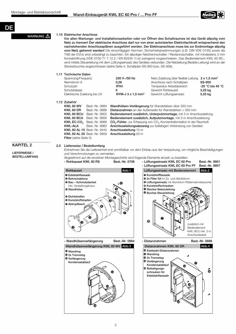
Entnehmen Sie die Liefereinheit erst unmittelbar vor dem Einbau aus der Verpackung, um mögliche Beschädigungenund Verschmutzungen zu vermeiden.Abgestimmt auf die einzelnen Montageschritte sind folgende Elemente einzeln zu bestellen:- Rohbauset KWL 60 RS Best .-Nr . 0708 - Lüftungseinsatz KWL EC 60 Pro Best .-Nr . 9951 - Lüftungseinsatz KWL EC 60 Pro FF Best .-Nr . 9957
- Wandhülsenverlängerung Best .-Nr . 0884 - Distanzrahmen Best .-Nr . 0888
KAPITEL 2
LIEFERWEISE /BESTELLUMFANG
2
Wand-Einbaugerät KWL EC 60 Pro / . . . Pro FFMontage- und Betriebsvorschrift
WARNUNG m
DE
Rohbauset
ë
ò
Abb .1
ùä
Lüftungseinsatz mit Bedienelement
ö
Abb .2
Å
î
ä
ä
ä
Ø
Æ
11
12
ü
ò Edelstahlfassadeù Bohrschabloneä Bau – Schmutzdeckel inkl. Versteifungskreuzë Wandhülse ö Dichtstreifenü KunststoffstopfenÅ Abtropfblech
Å Kunststofffassade î 2x Filter G4 im Zu- und AbluftstromØ Lüftungseinsatz mit Aluminium-PlattenwärmetauscherÆ Kunststoffschrauben Stecker Netzzuleitung Buchse Steuerleitung11
12
Å
zusätzlich mitBedienelementKWL-BCU inkl. 3 m Anschlusskabel.
Wandhülsenverlängerung KWL 60 WV Abb .3 Distanzrahmen KWL 60 DR Abb .4
20
18
Wandring2x TrennstegVerlängerung Kondensatablauf
Edelstahl-DistanzrahmenWandring2x Trennsteg Verlängerung KondensatablaufBefestigungs-schrauben fürEdelstahlfassade
19
17
16
16
17
18
19
20
13
14
15
14
15
13
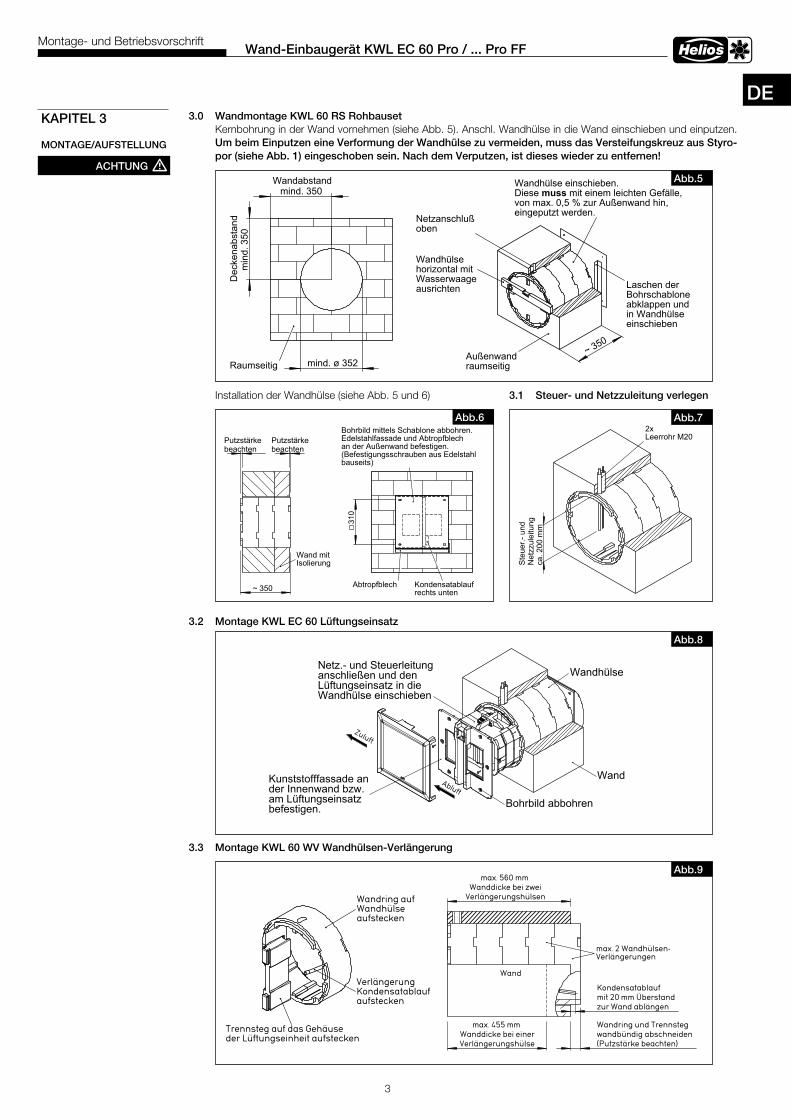
3 .0 Wandmontage KWL 60 RS Rohbauset Kernbohrung in der Wand vornehmen (siehe Abb. 5). Anschl. Wandhülse in die Wand einschieben und einputzen. Um beim Einputzen eine Verformung der Wandhülse zu vermeiden, muss das Versteifungskreuz aus Styro- por (siehe Abb . 1) eingeschoben sein . Nach dem Verputzen, ist dieses wieder zu entfernen!
Installation der Wandhülse (siehe Abb. 5 und 6) 3 .1 Steuer- und Netzzuleitung verlegen
3 .2 Montage KWL EC 60 Lüftungseinsatz
3 .3 Montage KWL 60 WV Wandhülsen-Verlängerung
3
Wand-Einbaugerät KWL EC 60 Pro / . . . Pro FFMontage- und Betriebsvorschrift
KAPITEL 3
MONTAGE/AUFSTELLUNG
mind. 350Wandabstand
min
d. 3
50D
ecke
nabs
tand
mind. ø 352Raumseitig~ 350
Wandhülse einschieben.Diese muss mit einem leichten Gefälle,von max. 0,5 % zur Außenwand hin,eingeputzt werden.
Außenwandraumseitig
Wandhülsehorizontal mitWasserwaageausrichten
Netzanschlußoben
Laschen derBohrschabloneabklappen undin Wandhülseeinschieben
Abb .5
beachtenPutzstärke
beachtenPutzstärke
~ 350
Wand mitIsolierung
310
Bohrbild mittels Schablone abbohren.Edelstahlfassade und Abtropfblechan der Außenwand befestigen.(Befestigungsschrauben aus Edelstahlbauseits)
Kondensatablaufrechts unten
Abtropfblech
Abb .6
ca. 2
00 m
m
Ste
uer.-
und
Net
zzul
eitu
ng
2xLeerrohr M20
Abb .7
Trennsteg auf das Gehäuseder Lüftungseinheit aufstecken
Wandring aufWandhülseaufstecken
VerlängerungKondensatablaufaufstecken
Abb .9max. 560 mm
Wanddicke bei zweiVerlängerungshülsen
(Putzstärke beachten)
Wandring und Trennstegwandbündig abschneiden
mit 20 mm Überstandzur Wand ablängen
Kondensatablauf
max. 455 mmWanddicke bei einerVerlängerungshülse
max. 2 Wandhülsen-Verlängerungen
Wand
ACHTUNG m
DE
Wand
WandhülseNetz.- und Steuerleitunganschließen und denLüftungseinsatz in dieWandhülse einschieben
Bohrbild abbohren
Kunststofffassade ander Innenwand bzw.am Lüftungseinsatzbefestigen.
Abb .8
310
370
~67~350
370
~40
~ 39
6
~ 21
Kernbohrungø 352 mm
Zuluft
Abluft
310
370
~67~350
370
~40
~ 39
6
~ 21
Kernbohrungø 352 mm
Zuluft
Abluft
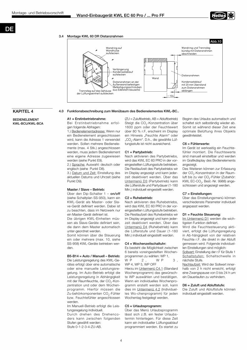
3 .4 Montage KWL 60 DR Distanzrahmen
4 .0 Funktionsbeschreibung zum Menübaum des Bedienelementes KWL-BC . .
4
Wand-Einbaugerät KWL EC 60 Pro / . . . Pro FFMontage- und Betriebsvorschrift
SS-932Trennsteg auf das Gehäuse
der Lüftungseinheit aufstecken
VerlängerungKondensatablaufaufstecken
Wandring aufWandhülseaufstecken
Distanzrahmen an derAußenwand befestigen(Befestigungsschraubenaus Edelstahl bauseits)
Abb .10
abschneiden
Wandring und Trennstegbündig mit Distanzrahmen
~ 104
mit 20 mm Überstandzum Distanzrahmenablängen
KondensatablaufWand
Distanzrahmen
KAPITEL 4
BEDIENELEMENT KWL-BCU/KWL-BCA
A1 = Erstinbetriebnahme:Bei Erst inbetr iebnahme er fo l -gen folgende Abfragen: 1.) Bedienelementadresse: Wenn nur ein Bedienelement angeschlossen wird, kann die Adresse 1 verwendet werden. Sollen mehrere Bedienele-mente (max. 4 Stk.) angeschlossen werden, muss jedem Bedienelement eine eigene Adresse zugewiesen werden (siehe Punkt E9). 2.) Sprache: Auswahl: deutsch oder englisch (siehe Punkt D8). 3.) Datum und Zeit: Einstellung des aktuellen Datums und Uhrzeit (siehe Punkt D9).
Master / Slave – Betrieb:Über den Dip-Schalter 1 – on/off (siehe Schaltplan SS-950), kann ein KWL-Gerät als Master- oder Sla-ve-Gerät definiert werden. Dabei ist zu beachten, dass im Netzwerk nur ein Master-Gerät definiert ist.Die übrigen KWL-Einheiten müs-sen als Slave-Geräte definiert sein, die dann dem Master automatisch unter-geordnet werden. Somit können über die Steuerung ein oder mehrere (max. 10, siehe SS-958) KWL-Geräte betrieben wer-den.
B5-B14 = Auto / Manuell – Betrieb: Die Leistungsregelung des KWL-Ge-rätes erfolgt über eine automatische oder eine manuelle Leistungsre-gelung. Im Auto-Betrieb erfolgt die Leistungsregelung in Abhängigkeit mit der Raumfeuchte, der CO2-Kon-zentration und oder dem Wochen-programm. Hierfür müssen die Zu-behörkomponenten CO2-Fühler bzw. Feuchtefühler angeschlossen werden. Im Manuell-Betrieb erfolgt die Leis-tungsregelung individuell. Durch drehen des Drehenco-ders kann zwischen folgenden Stufen gewählt werden: Stufe 0-1-2-3-4-ZU-AB.
(ZU = Zuluftbetrieb, AB = Abluftbetrieb) Steigt die CO2-Konzentration über 1600 ppm oder der Feuchtewert über 80 % r.F, erscheint im Display ein Hinweis „Feuchte Alarm“ oder „CO2-Alarm“. D.h., die gewählte Lüf-tungsstufe ist nicht ausreichend.
C1 = Partybetrieb: Nach aktivieren des Partybetriebs, wird das KWL EC 60 PRO in der vor-eingestellten Lüftungsstufe betrieben. Die Restlaufzeit des Partybetriebs wir im Display angezeigt und kann jeder-zeit deaktiviert werden. Über das Untermenü D3 (Partybetrieb) kann die Lüfterstufe und Partydauer (1-180 Min.) individuell eingestellt werden.
C2 = Ruhebetrieb:Nach aktivieren des Ruhebetriebs, wird das KWL EC 60 PRO in der vor-eingestellten Lüftungsstufe betrieben. Die Restlaufzeit des Ruhebetriebs wir im Display angezeigt und kann jeder-zeit deaktiviert werden. Über das Untermenü D4 (Ruhebetrieb) kann die Lüfterstufe und Dauer (1-180 Min.) individuell eingestellt werden.
C4 = Wochenzeitschaltuhr:Es besteht die Möglichkeit zwischen 6 bereits voreingestellten Wochen-programmen zu wählen: WP 1, W P 2 , W P 3 , WP 4, WP 5, WP OFF Hierzu im Untermenü C4.1 (Standard Wochenprogramm) das gewünsch-te WP auswählen und bestätigen. Wenn ein individuelles Wochenpro-gramm erstellt werden soll, kann dies im Untermenü 4.2 (Individuel-les Wo-chenprogramm) für jeden Wochentag festgelegt werden.
C5 = Urlaubsprogramm:Über das Menü Urlaubsprogramm lässt sich z.B. ein fester Urlaubs-termin hinterlegen. Für diese Zeit kann ein individueller Lüftungsablauf programmiert werden. Es startet zu
Beginn des Urlaubs automatisch und schaltet sich selbständig wieder ab. Somit ist während dieser Zeit eine optimale Belüftung ihres Objekts gewährleistet.
C6 = Fühlerwerte:Im Gerät ist werkseitig ein Feuchte-fühler montiert. Die Feuchtewerte sind manuell einstellbar und werden im Grafikdisplay des Bedienelements angezeigt. Des Weiteren können zur Erfassung der CO2-Konzentraton in der Raum-luft bis zu vier CO2-Fühler (Zubehör: KWL EC-CO2, Best.-Nr. 9988) ange-schlossen und angezeigt werden. C7 = Einstellungen:Über das Einstellungsmenü können verschiedenste Parameter individuell angepasst werden.
D1 = Feuchte Steuerung:Im Untermenü D1 werden die wich-tigsten Funktion definiert.Wird die Feuchtesteuerung akti-viert, erfolgt die Lüftungsregelung in Ab-hängigkeit von der relativen Feuchte r.F. die direkt in der Abluft gemessen wird. Folgende individuel-len Einstellungen sind möglich: Sollwert: Einstellung der r.F für Stufe 1Schaltstufen: Schaltschwelle in nächste Stufe.Nachlaufzeit: Wird der Sollwert inner-halb von 2 h nicht erreicht, erfolgt eine Zwangspause von 0 bis 24 h um ein Dauerlaufen zu verhindern.
D6 = Zuluft und Abluftstufe:Die Zuluft und Abluftstufe können individuell eingestellt werden.
DE
5
Wand-Einbaugerät KWL EC 60 Pro / . . . Pro FFMontage- und Betriebsvorschrift
D7 = Filterwechsel:Das Filterwechselintervall kann zwi-schen 2 bis 9 Monaten eingestellt werden. Über eine Abfrage, kann die Restlaufzeit für den Filterwechsel an-gezeigt werden. Bei einem vorzei-tigen Filterwechsel, muss die Rest-laufzeit resetet werden.
D8 = Sprache: Sprachauswahl zwischen Deutsch oder Englisch.
D9 = Datum und Zeit: Einstellung des aktuellen Datums und Uhrzeit (Zeitzone). D10 = Display Nachleuchtzeit:Die Nachleuchtzeit des Displays kann zwischen 5 - 30 sec. einge-stellt werden. Findet für diese Zeit keine Be-stätigung am Bedienele-ment statt, erlischt das Display und die Steuerung springt in die oberste Menüebene zurück.
D11= Wellenbeleuchtung: Findelicht: Wenn das Display aus ist, wird die Welle des Drehencoders blau beleuchtet. Die Helligkeit kann zwischen 0 - 100 % eingestellt wer-den. Störungsanzeige: Wenn das Display aus ist und ein Fehler vorliegt, blinkt die Welle des Drehencoders rot auf. Die Helligkeit kann zwischen 20 -100 % eingestellt werden.
D12 = Servicemenü:Über das Servicemenü können ver-schiedenste Parameter individu-ell an-gepasst werden. Um in das passwortgeschützte Menü zu gelangen, Kennwort 5255 einge-ben.E1 = Betriebsstundenanzeige:Die Zählung der Betriebstunden er-folgt sobald ein oder beide Venti-latoren in Betrieb sind. Eine Rückset-zung der Betriebsstunden ist nur im Werk möglich.
E2 = Wärmetauscher Frostschutz:0 bis 10 °C
E3 = Mind . Lüfterstufe:Die mind. Lüfterstufe kann zwischen 0 bis 1 eingestellt werden. Ist Stufe 0 definiert, kann das KWL-Gerät aus-geschaltet werden. Ist Stufe 1 defi-niert, kann die Stufe 0 nicht aktiviert werden, auch nicht im Wochenpro-gramm.
E9 = Adresse Bedienelement:Die Adresse des Bedienelements kann nachträglich geändert wer-den. Dabei ist zu beachten, dass die Adressen immer nur einmal vergeben sind. Es können max. vier Bedienele-mente angeschlossen werden.
E11 = Software Version: Abfrage zum Software-Versions-stand der Hauptplatine und des Bedienelements.
E12 = Rücksetzen auf Werksein-stellungen:Alle Parameter können auf die Werkseinstellung zurückgesetzt wer-den. Wenn die Einstellungen des Wochenprogramm nicht resetet werden sollen, ist dies vorab optional einstellbar.
E13 = Motorüberwachung/ Fehlermanagement:Lüfterstufe 1:1. Bei einem Drehzahlfehler in LS 1 der länger als 30 sek dauert, schaltet das Gerät in LS 2.2. Besteht der Fehler nach einer 1min immer noch, bleibt das Gerät in LS 2. Besteht der Fehler nicht mehr, wech-selt das Gerät wieder in LS 1. Lüfterstufe 2 - 4:In diesen Lüfterstufen findet keine automatische Umschaltung auf eine andere Lüfterstufe statt.
Hinweis: Unabhängig von der Fehlerauswertung über das Dreh-zahlsignal hat der Motor ein eige-nes Fehlermanagement, das bei Block-ierung abschaltet und zyk-lisch ein Einschalten probiert .
Fehlercode:E1 è Statusleitung Lüfter „Zuluft“ E2 è Statusleitung Lüfter „Abluft“ E3 è Überschreitung Maximalstrom „Zuluft“ E4 è Überschreitung Maximalstrom „Abluft“ E5 è Unterschreitung Minimaler-strom „Zuluft“ E6 è Unterschreitung Minimaler-strom „Abluft“ E7 è Klemmenkurzschluss „Zuluft“ E8 è Klemmenkurzschluss „Abluft“E9 è Versorgungsspannung 24 V
E = 14 Lüfterstufe:Wird das EC 60 Gerät eingeschaltet, geht es für 4 Sek in einen Boostmo-dus, statt LS 1 läuft LS 2.Während dem Boostmodus wird im Display statt „manuell”, „Autobetrieb” angezeigt.
DE
6
Wand-Einbaugerät KWL EC 60 Pro / . . . Pro FFMontage- und Betriebsvorschrift
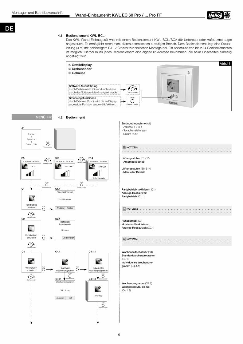
4 .1 Bedienelement KWL-BC . . Das KWL-Wand-Einbaugerät wird mit einem Bedienelement KWL-BCU/BCA (für Unterputz oder Aufputzmontage) angesteuert. Es ermöglicht einen manuellen/automatischen 4-stufigen Betrieb. Dem Bedienelement liegt eine Steuer- leitung (3 m) mit beidseitigem RJ 12 Stecker zur einfachen Montage bei. Ein Anschluss von bis zu 4 Bedienelementen ist möglich. Hierbei muss jedes Bedienelement eine eigene IP-Adresse bekommen, die beim Einschalten einmalig abgefragt wird.
4 .2 Bedienmenü
â
ê
ô
â Grafikdisplayê Drehencoder ô Gehäuse
Software-Menüführung durch Drehen nach links und rechts kann durch das Software-Menü navigiert werden.
Steuerungsfunktionendurch Drücken (Push), wird die im Display angezeigte Funktion ausgewählt/aktiviert.
Erstinbetriebnahme (A1)- Adresse 1-2-3-4- Spracheinstellungen- Datum / Uhr
Lüftungsstufen (B1-B7) - Automatikbetrieb Lüftungsstufen (B8-B14) - Manueller Betrieb
Partybetrieb aktivieren (C1)Anzeige Restlaufzeit Partybetrieb (C1.1)
Ruhebetrieb (C2) aktivieren/deaktivieren Anzeige Restlaufzeit (C2.1)
Wochenzeitschaltuhr (C4)Standardwochenprogramm (C4.1)Individuelles Wochenpro-gramm (C4.1.1)
Wochenprogramm (C4.2)Wochentag Mo . bis So . (C4.1.2)
MENÜ +
�NOTIZEN: . . . . . . . . . . . . . . . . . . . . . . . . . . . . . . . . . . . . . . . . . . . . . . . . . . . . . . . . . . . . . . . . . . . . . . . . . . . . . . . . . . . . . . . . . . . . . . . . . . . . . . . . . . . . . . . . . . . . . . . . . . . . . . . . . . . . . . . . .
�NOTIZEN: . . . . . . . . . . . . . . . . . . . . . . . . . . . . . . . . . . . . . . . . . . . . . . . . . . . . . . . . . . . . . . . . . . . . . . . . . . . . . . . . . . . . . . . . . . . . . . . . . . . . . . . . . . . . . . . . . . . . . . . . . . . . . . . . . . . . . . . . .
A1
C1 C1 .1
B5 B10 B14
C2 C2 .1
C4 C4 .1
C4 .2
C4 .1 .1
�NOTIZEN: . . . . . . . . . . . . . . . . . . . . . . . . . . . . . . . . . . . . . . . . . . . . . . . . . . . . . . . . . . . . . . . . . . . . . . . . . . . . . . . . . . . . . . . . . . . . . . . . . . . . . . . . . . . . . . . . . . . . . . . . . . . . . . . . . . . . . . . . .
C4 .1 .2
Abb .11
DE
7
Wand-Einbaugerät KWL EC 60 Pro / . . . Pro FFMontage- und Betriebsvorschrift
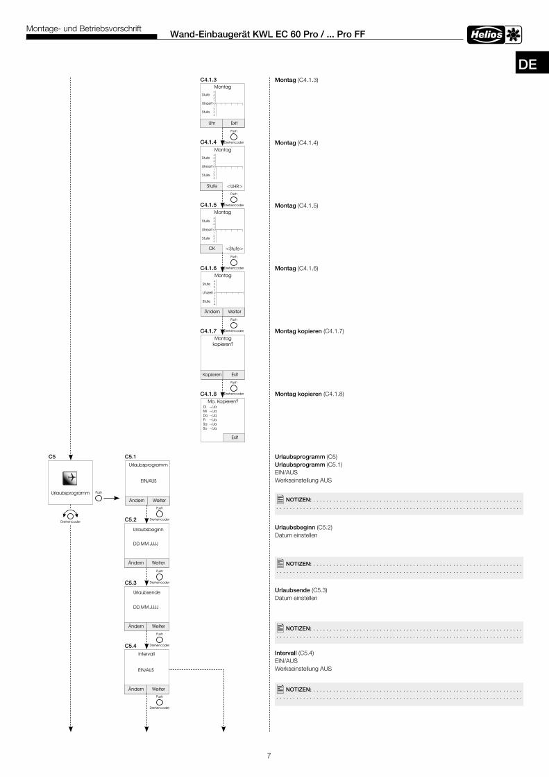
Montag (C4.1.3)
Montag (C4.1.4)
Montag (C4.1.5)
Montag (C4.1.6)
Montag kopieren (C4.1.7)
Montag kopieren (C4.1.8)
Urlaubsprogramm (C5) Urlaubsprogramm (C5.1)EIN/AUSWerkseinstellung AUS
Urlaubsbeginn (C5.2) Datum einstellen
Urlaubsende (C5.3) Datum einstellen
Intervall (C5.4)EIN/AUSWerkseinstellung AUS
C5 C5 .1
C4 .1 .3
C5 .2
C5 .3
C5 .4
C4 .1 .4
C4 .1 .5
C4 .1 .6
C4 .1 .7
C4 .1 .8
�NOTIZEN: . . . . . . . . . . . . . . . . . . . . . . . . . . . . . . . . . . . . . . . . . . . . . . . . . . . . . . . . . . . . . . . . . . . . . . . . . . . . . . . . . . . . . . . . . . . . . . . . . . . . . . . . . . . . . . . . . . . . . . . . . . . . . . . . . . . . . . . . .
�NOTIZEN: . . . . . . . . . . . . . . . . . . . . . . . . . . . . . . . . . . . . . . . . . . . . . . . . . . . . . . . . . . . . . . . . . . . . . . . . . . . . . . . . . . . . . . . . . . . . . . . . . . . . . . . . . . . . . . . . . . . . . . . . . . . . . . . . . . . . . . . . .
�NOTIZEN: . . . . . . . . . . . . . . . . . . . . . . . . . . . . . . . . . . . . . . . . . . . . . . . . . . . . . . . . . . . . . . . . . . . . . . . . . . . . . . . . . . . . . . . . . . . . . . . . . . . . . . . . . . . . . . . . . . . . . . . . . . . . . . . . . . . . . . . . .
�NOTIZEN: . . . . . . . . . . . . . . . . . . . . . . . . . . . . . . . . . . . . . . . . . . . . . . . . . . . . . . . . . . . . . . . . . . . . . . . . . . . . . . . . . . . . . . . . . . . . . . . . . . . . . . . . . . . . . . . . . . . . . . . . . . . . . . . . . . . . . . . . .
DE
8
Wand-Einbaugerät KWL EC 60 Pro / . . . Pro FFMontage- und Betriebsvorschrift
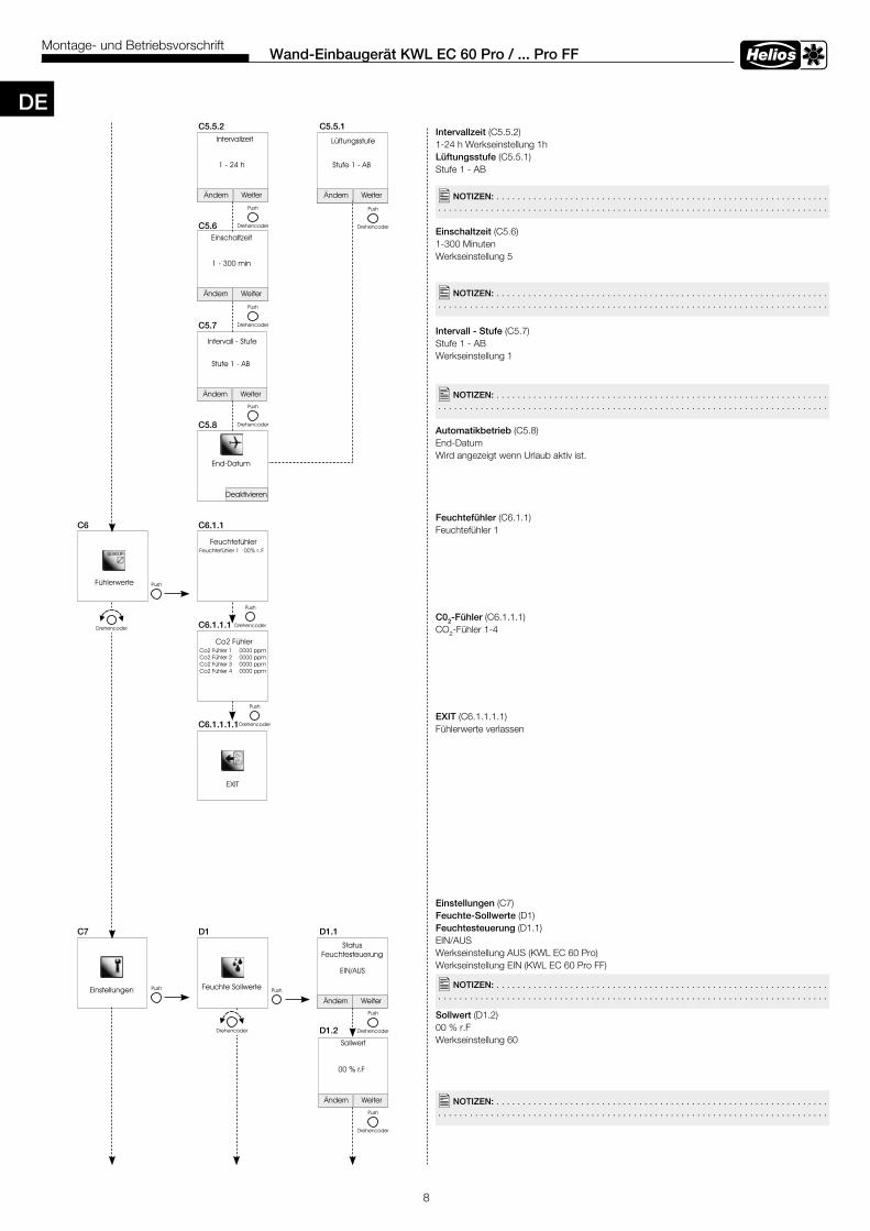
Intervallzeit (C5.5.2)1-24 h Werkseinstellung 1hLüftungsstufe (C5.5.1)Stufe 1 - AB
Einschaltzeit (C5.6)1-300 MinutenWerkseinstellung 5
Intervall - Stufe (C5.7)Stufe 1 - ABWerkseinstellung 1
Automatikbetrieb (C5.8)End-Datum Wird angezeigt wenn Urlaub aktiv ist.
Feuchtefühler (C6.1.1)Feuchtefühler 1
C02-Fühler (C6.1.1.1)CO2-Fühler 1-4
EXIT (C6.1.1.1.1)Fühlerwerte verlassen
Einstellungen (C7)Feuchte-Sollwerte (D1)Feuchtesteuerung (D1.1)EIN/AUSWerkseinstellung AUS (KWL EC 60 Pro)Werkseinstellung EIN (KWL EC 60 Pro FF)
Sollwert (D1.2)00 % r.F Werkseinstellung 60
C5 .5 .2 C5 .5 .1
C5 .6
C5 .7
C5 .8
�NOTIZEN: . . . . . . . . . . . . . . . . . . . . . . . . . . . . . . . . . . . . . . . . . . . . . . . . . . . . . . . . . . . . . . . . . . . . . . . . . . . . . . . . . . . . . . . . . . . . . . . . . . . . . . . . . . . . . . . . . . . . . . . . . . . . . . . . . . . . . . . . .
C6 C6 .1 .1
C6 .1 .1 .1
C6 .1 .1 .1 .1
C7 D1 D1 .1
D1 .2
�NOTIZEN: . . . . . . . . . . . . . . . . . . . . . . . . . . . . . . . . . . . . . . . . . . . . . . . . . . . . . . . . . . . . . . . . . . . . . . . . . . . . . . . . . . . . . . . . . . . . . . . . . . . . . . . . . . . . . . . . . . . . . . . . . . . . . . . . . . . . . . . . .
�NOTIZEN: . . . . . . . . . . . . . . . . . . . . . . . . . . . . . . . . . . . . . . . . . . . . . . . . . . . . . . . . . . . . . . . . . . . . . . . . . . . . . . . . . . . . . . . . . . . . . . . . . . . . . . . . . . . . . . . . . . . . . . . . . . . . . . . . . . . . . . . . .
�NOTIZEN: . . . . . . . . . . . . . . . . . . . . . . . . . . . . . . . . . . . . . . . . . . . . . . . . . . . . . . . . . . . . . . . . . . . . . . . . . . . . . . . . . . . . . . . . . . . . . . . . . . . . . . . . . . . . . . . . . . . . . . . . . . . . . . . . . . . . . . . . .
�NOTIZEN: . . . . . . . . . . . . . . . . . . . . . . . . . . . . . . . . . . . . . . . . . . . . . . . . . . . . . . . . . . . . . . . . . . . . . . . . . . . . . . . . . . . . . . . . . . . . . . . . . . . . . . . . . . . . . . . . . . . . . . . . . . . . . . . . . . . . . . . . .
DE
9
Wand-Einbaugerät KWL EC 60 Pro / . . . Pro FFMontage- und Betriebsvorschrift
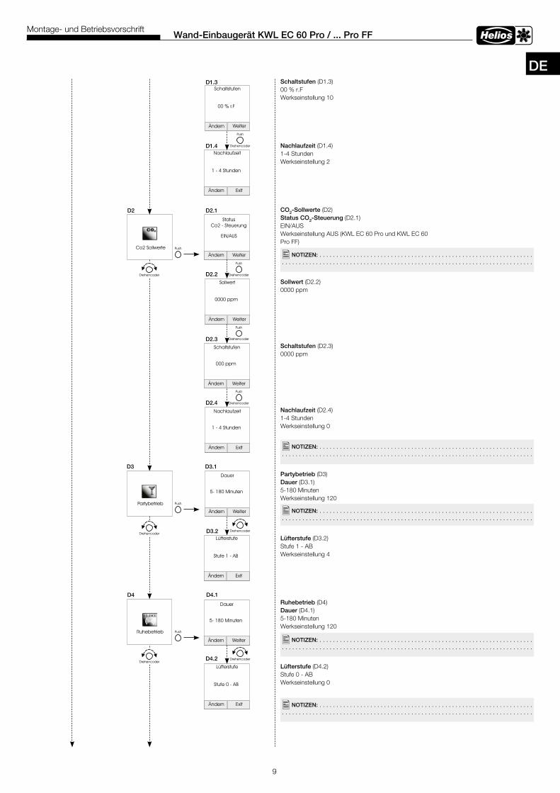
Schaltstufen (D1.3)00 % r.FWerkseinstellung 10
Nachlaufzeit (D1.4)1-4 StundenWerkseinstellung 2
CO2-Sollwerte (D2)Status CO2-Steuerung (D2.1)EIN/AUSWerkseinstellung AUS (KWL EC 60 Pro und KWL EC 60 Pro FF)
Sollwert (D2.2)0000 ppm
Schaltstufen (D2.3)0000 ppm
Nachlaufzeit (D2.4) 1-4 StundenWerkseinstellung 0
Partybetrieb (D3)Dauer (D3.1)5-180 MinutenWerkseinstellung 120
Lüfterstufe (D3.2)Stufe 1 - ABWerkseinstellung 4
Ruhebetrieb (D4)Dauer (D4.1)5-180 MinutenWerkseinstellung 120
Lüfterstufe (D4.2)Stufe 0 - AB Werkseinstellung 0
D1 .3
D1 .4
D2 D2 .1
D3 D3 .1
D2 .2
D2 .3
D2 .4
D4 .2
D3 .2
D4 .1D4
�NOTIZEN: . . . . . . . . . . . . . . . . . . . . . . . . . . . . . . . . . . . . . . . . . . . . . . . . . . . . . . . . . . . . . . . . . . . . . . . . . . . . . . . . . . . . . . . . . . . . . . . . . . . . . . . . . . . . . . . . . . . . . . . . . . . . . . . . . . . . . . . . .
�NOTIZEN: . . . . . . . . . . . . . . . . . . . . . . . . . . . . . . . . . . . . . . . . . . . . . . . . . . . . . . . . . . . . . . . . . . . . . . . . . . . . . . . . . . . . . . . . . . . . . . . . . . . . . . . . . . . . . . . . . . . . . . . . . . . . . . . . . . . . . . . . .
�NOTIZEN: . . . . . . . . . . . . . . . . . . . . . . . . . . . . . . . . . . . . . . . . . . . . . . . . . . . . . . . . . . . . . . . . . . . . . . . . . . . . . . . . . . . . . . . . . . . . . . . . . . . . . . . . . . . . . . . . . . . . . . . . . . . . . . . . . . . . . . . . .
�NOTIZEN: . . . . . . . . . . . . . . . . . . . . . . . . . . . . . . . . . . . . . . . . . . . . . . . . . . . . . . . . . . . . . . . . . . . . . . . . . . . . . . . . . . . . . . . . . . . . . . . . . . . . . . . . . . . . . . . . . . . . . . . . . . . . . . . . . . . . . . . . .
�NOTIZEN: . . . . . . . . . . . . . . . . . . . . . . . . . . . . . . . . . . . . . . . . . . . . . . . . . . . . . . . . . . . . . . . . . . . . . . . . . . . . . . . . . . . . . . . . . . . . . . . . . . . . . . . . . . . . . . . . . . . . . . . . . . . . . . . . . . . . . . . . .
DE
10
Wand-Einbaugerät KWL EC 60 Pro / . . . Pro FFMontage- und Betriebsvorschrift
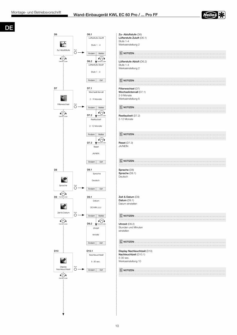
Zu- Abluftstufe (D6)Lüfterstufe Zuluft (D6.1)Stufe 1-4Werkseinstellung 2
Lüfterstufe Abluft (D6.2)Stufe 1-4Werkseinstellung 2
Filterwechsel (D7)Wechselintervall (D7.1)2-9 MonateWerkseinstellung 6
Restlaufzeit (D7.2)2-12 Monate
Reset (D7.3)JA/NEIN
Sprache (D8) Sprache (D8.1)Deutsch
Zeit & Datum (D9)Datum (D9.1)Datum einstellen
Uhrzeit (D9.2)Stunden und Minuten einstellen
Display Nachleuchtzeit (D10)Nachleuchtzeit (D10.1)5-30 sec.Werkseinstellung 10
D6 D6 .1
D6 .2
D7 D7 .1
D7 .2
D7 .3
D8 .1
D9 .1
D9 .2
D8
D9
D10 .1D10
�NOTIZEN: . . . . . . . . . . . . . . . . . . . . . . . . . . . . . . . . . . . . . . . . . . . . . . . . . . . . . . . . . . . . . . . . . . . . . . . . . . . . . . . . . . . . . . . . . . . . . . . . . . . . . . . . . . . . . . . . . . . . . . . . . . . . . . . . . . . . . . . . .
�NOTIZEN: . . . . . . . . . . . . . . . . . . . . . . . . . . . . . . . . . . . . . . . . . . . . . . . . . . . . . . . . . . . . . . . . . . . . . . . . . . . . . . . . . . . . . . . . . . . . . . . . . . . . . . . . . . . . . . . . . . . . . . . . . . . . . . . . . . . . . . . . .
�NOTIZEN: . . . . . . . . . . . . . . . . . . . . . . . . . . . . . . . . . . . . . . . . . . . . . . . . . . . . . . . . . . . . . . . . . . . . . . . . . . . . . . . . . . . . . . . . . . . . . . . . . . . . . . . . . . . . . . . . . . . . . . . . . . . . . . . . . . . . . . . . .
�NOTIZEN: . . . . . . . . . . . . . . . . . . . . . . . . . . . . . . . . . . . . . . . . . . . . . . . . . . . . . . . . . . . . . . . . . . . . . . . . . . . . . . . . . . . . . . . . . . . . . . . . . . . . . . . . . . . . . . . . . . . . . . . . . . . . . . . . . . . . . . . . .
�NOTIZEN: . . . . . . . . . . . . . . . . . . . . . . . . . . . . . . . . . . . . . . . . . . . . . . . . . . . . . . . . . . . . . . . . . . . . . . . . . . . . . . . . . . . . . . . . . . . . . . . . . . . . . . . . . . . . . . . . . . . . . . . . . . . . . . . . . . . . . . . . .
�NOTIZEN: . . . . . . . . . . . . . . . . . . . . . . . . . . . . . . . . . . . . . . . . . . . . . . . . . . . . . . . . . . . . . . . . . . . . . . . . . . . . . . . . . . . . . . . . . . . . . . . . . . . . . . . . . . . . . . . . . . . . . . . . . . . . . . . . . . . . . . . . .
�NOTIZEN: . . . . . . . . . . . . . . . . . . . . . . . . . . . . . . . . . . . . . . . . . . . . . . . . . . . . . . . . . . . . . . . . . . . . . . . . . . . . . . . . . . . . . . . . . . . . . . . . . . . . . . . . . . . . . . . . . . . . . . . . . . . . . . . . . . . . . . . . .
�NOTIZEN: . . . . . . . . . . . . . . . . . . . . . . . . . . . . . . . . . . . . . . . . . . . . . . . . . . . . . . . . . . . . . . . . . . . . . . . . . . . . . . . . . . . . . . . . . . . . . . . . . . . . . . . . . . . . . . . . . . . . . . . . . . . . . . . . . . . . . . . . .
DE
11
Wand-Einbaugerät KWL EC 60 Pro / . . . Pro FFMontage- und Betriebsvorschrift
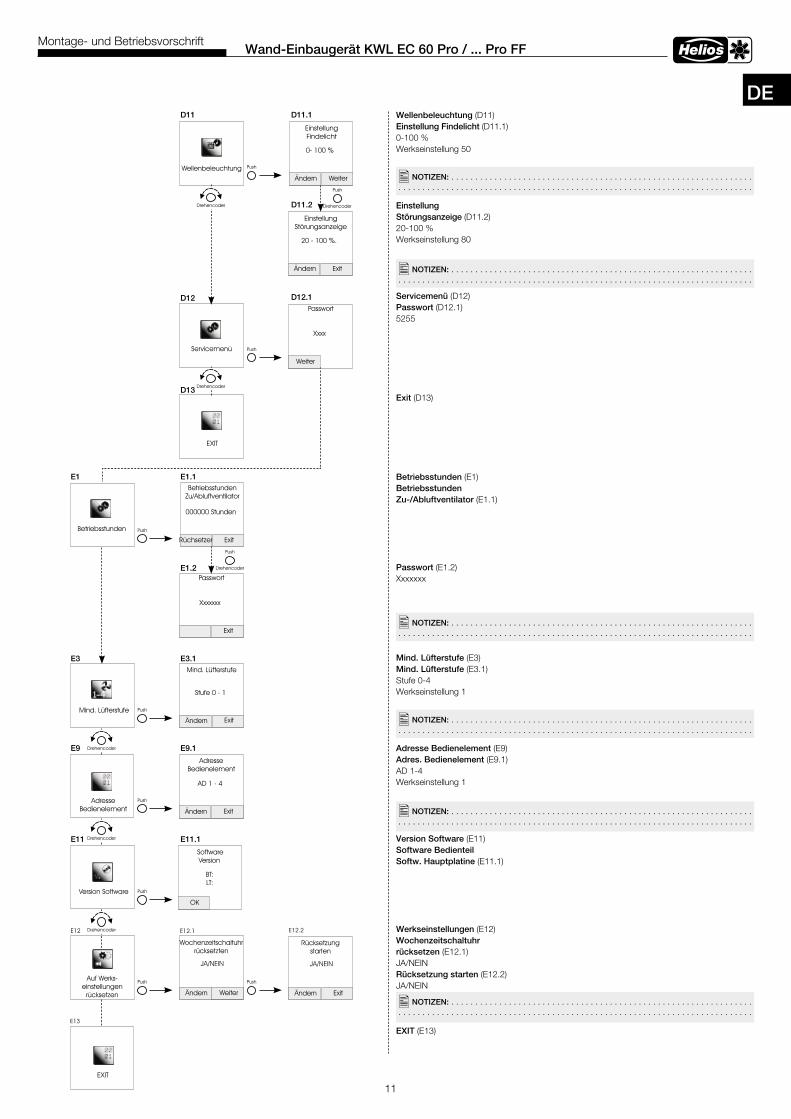
Wellenbeleuchtung (D11)Einstellung Findelicht (D11.1)0-100 %Werkseinstellung 50
Einstellung Störungsanzeige (D11.2)20-100 %Werkseinstellung 80
Servicemenü (D12) Passwort (D12.1) 5255
Exit (D13)
Betriebsstunden (E1)Betriebsstunden Zu-/Abluftventilator (E1.1)
Passwort (E1.2) Xxxxxxx
Mind . Lüfterstufe (E3)Mind . Lüfterstufe (E3.1)Stufe 0-4Werkseinstellung 1
Adresse Bedienelement (E9)Adres . Bedienelement (E9.1)AD 1-4Werkseinstellung 1
Version Software (E11)Software Bedienteil Softw . Hauptplatine (E11.1)
Werkseinstellungen (E12)Wochenzeitschaltuhrrücksetzen (E12.1)JA/NEINRücksetzung starten (E12.2)JA/NEIN
EXIT (E13)
D11 D11 .1
E1
D11 .2
D13
D12 .1D12
E1 .1
E1 .2
E3 E3 .1
E9 E9 .1
E11 E11 .1
�NOTIZEN: . . . . . . . . . . . . . . . . . . . . . . . . . . . . . . . . . . . . . . . . . . . . . . . . . . . . . . . . . . . . . . . . . . . . . . . . . . . . . . . . . . . . . . . . . . . . . . . . . . . . . . . . . . . . . . . . . . . . . . . . . . . . . . . . . . . . . . . . .
�NOTIZEN: . . . . . . . . . . . . . . . . . . . . . . . . . . . . . . . . . . . . . . . . . . . . . . . . . . . . . . . . . . . . . . . . . . . . . . . . . . . . . . . . . . . . . . . . . . . . . . . . . . . . . . . . . . . . . . . . . . . . . . . . . . . . . . . . . . . . . . . . .
�NOTIZEN: . . . . . . . . . . . . . . . . . . . . . . . . . . . . . . . . . . . . . . . . . . . . . . . . . . . . . . . . . . . . . . . . . . . . . . . . . . . . . . . . . . . . . . . . . . . . . . . . . . . . . . . . . . . . . . . . . . . . . . . . . . . . . . . . . . . . . . . . .
�NOTIZEN: . . . . . . . . . . . . . . . . . . . . . . . . . . . . . . . . . . . . . . . . . . . . . . . . . . . . . . . . . . . . . . . . . . . . . . . . . . . . . . . . . . . . . . . . . . . . . . . . . . . . . . . . . . . . . . . . . . . . . . . . . . . . . . . . . . . . . . . . .
�NOTIZEN: . . . . . . . . . . . . . . . . . . . . . . . . . . . . . . . . . . . . . . . . . . . . . . . . . . . . . . . . . . . . . . . . . . . . . . . . . . . . . . . . . . . . . . . . . . . . . . . . . . . . . . . . . . . . . . . . . . . . . . . . . . . . . . . . . . . . . . . . .
�NOTIZEN: . . . . . . . . . . . . . . . . . . . . . . . . . . . . . . . . . . . . . . . . . . . . . . . . . . . . . . . . . . . . . . . . . . . . . . . . . . . . . . . . . . . . . . . . . . . . . . . . . . . . . . . . . . . . . . . . . . . . . . . . . . . . . . . . . . . . . . . . .
DE
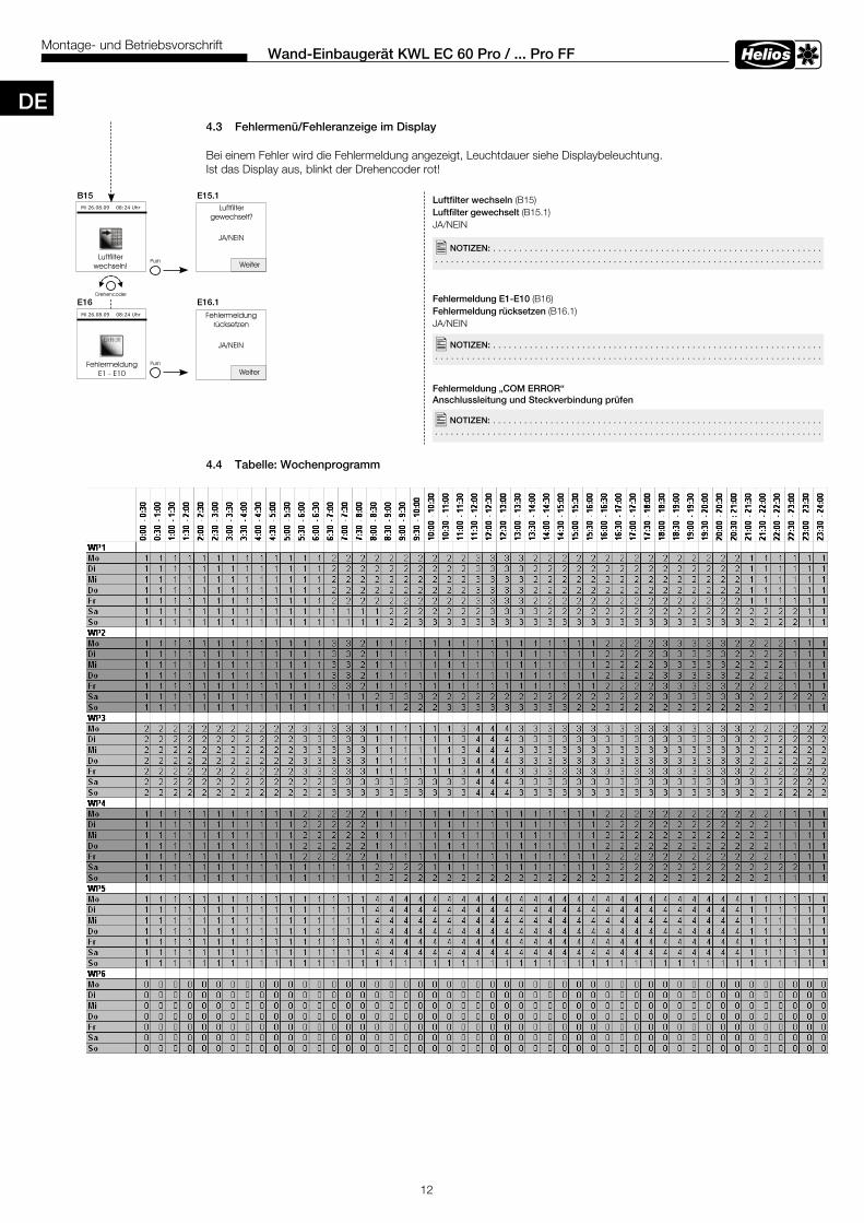
4 .3 Fehlermenü/Fehleranzeige im Display
Bei einem Fehler wird die Fehlermeldung angezeigt, Leuchtdauer siehe Displaybeleuchtung.Ist das Display aus, blinkt der Drehencoder rot!
4 .4 Tabelle: Wochenprogramm
12
Wand-Einbaugerät KWL EC 60 Pro / . . . Pro FFMontage- und Betriebsvorschrift
Luftfilter wechseln (B15)Luftfilter gewechselt (B15.1)JA/NEIN
Fehlermeldung E1-E10 (B16)Fehlermeldung rücksetzen (B16.1)JA/NEIN
Fehlermeldung „COM ERROR“Anschlussleitung und Steckverbindung prüfen
�NOTIZEN: . . . . . . . . . . . . . . . . . . . . . . . . . . . . . . . . . . . . . . . . . . . . . . . . . . . . . . . . . . . . . . . . . . . . . . . . . . . . . . . . . . . . . . . . . . . . . . . . . . . . . . . . . . . . . . . . . . . . . . . . . . . . . . . . . . . . . . . . .
�NOTIZEN: . . . . . . . . . . . . . . . . . . . . . . . . . . . . . . . . . . . . . . . . . . . . . . . . . . . . . . . . . . . . . . . . . . . . . . . . . . . . . . . . . . . . . . . . . . . . . . . . . . . . . . . . . . . . . . . . . . . . . . . . . . . . . . . . . . . . . . . . .
B15 E15 .1
E16 E16 .1
12
Wand-Einbaugerät KWL EC 60 Pro / ... Pro FFMontage- und Betriebsvorschrift
Luftfilter wechseln (B15)Luftfilter gewechselt (B15.1)JA/NEIN
Fehlermeldung E1-E10 (B16)Fehlermeldung rücksetzen(B16.1)JA/NEIN
4.3 Fehlermenü/Fehleranzeige im Display
Bei einem Fehler wird die Fehlermeldung angezeigt, Leuchtdauer siehe Displaybeleuchtung.Ist das Display aus, blinkt der Drehencoder rot!
4.4 Tabelle: Wochenprogramm
B15 E15.1
E16 E16.1
�NOTIZEN: . . . . . . . . . . . . . . . . . . . . . . . . . . . . . . . . . . . . . . . . . . . . . . . . . . . . . . . . . . . . . . .
�NOTIZEN: . . . . . . . . . . . . . . . . . . . . . . . . . . . . . . . . . . . . . . . . . . . . . . . . . . . . . . . . . . . . . . .
D
�NOTIZEN: . . . . . . . . . . . . . . . . . . . . . . . . . . . . . . . . . . . . . . . . . . . . . . . . . . . . . . . . . . . . . . . . . . . . . . . . . . . . . . . . . . . . . . . . . . . . . . . . . . . . . . . . . . . . . . . . . . . . . . . . . . . . . . . . . . . . . . . . .
DE
13
Wand-Einbaugerät KWL EC 60 Pro / . . . Pro FFMontage- und Betriebsvorschrift
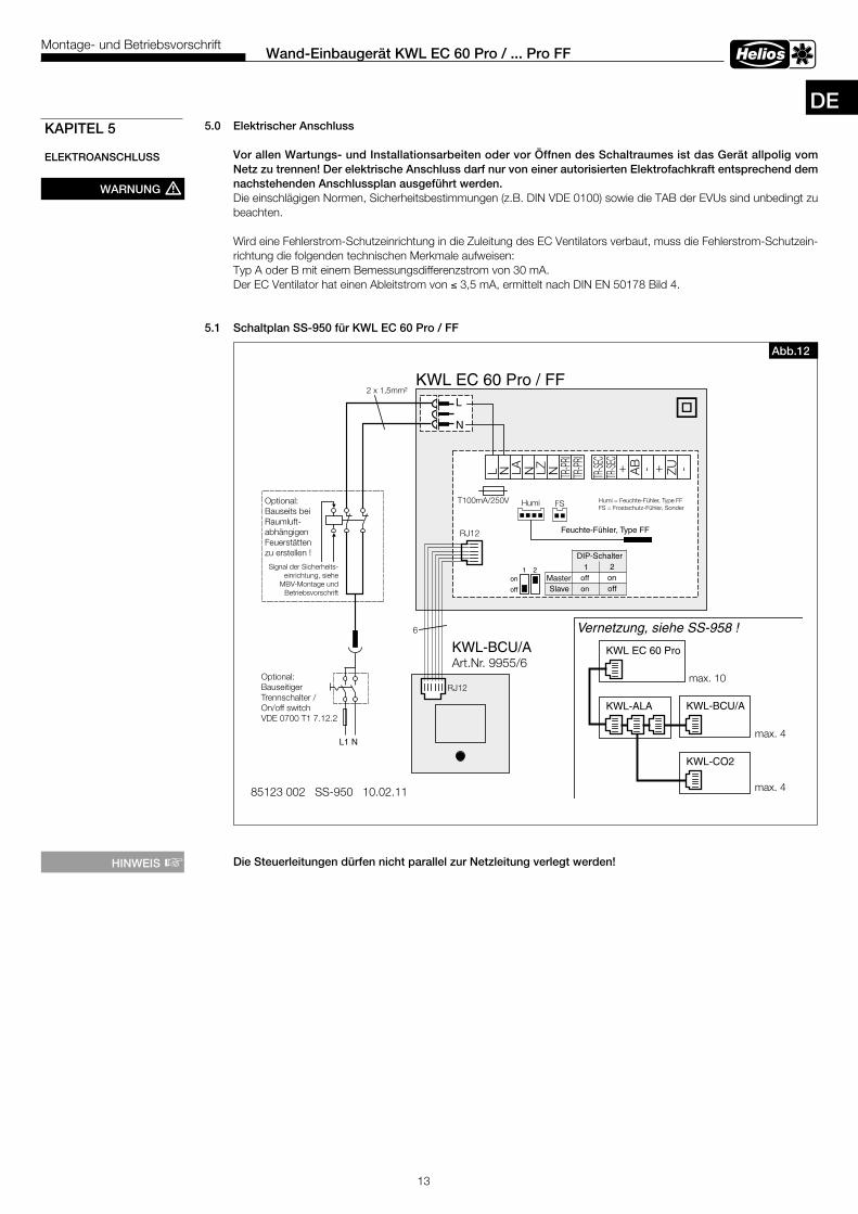
5 .0 Elektrischer Anschluss
Vor allen Wartungs- und Installationsarbeiten oder vor Öffnen des Schaltraumes ist das Gerät allpolig vom Netz zu trennen! Der elektrische Anschluss darf nur von einer autorisierten Elektrofachkraft entsprechend dem nachstehenden Anschlussplan ausgeführt werden . Die einschlägigen Normen, Sicherheitsbestimmungen (z.B. DIN VDE 0100) sowie die TAB der EVUs sind unbedingt zu beachten.
Wird eine Fehlerstrom-Schutzeinrichtung in die Zuleitung des EC Ventilators verbaut, muss die Fehlerstrom-Schutzein-richtung die folgenden technischen Merkmale aufweisen:Typ A oder B mit einem Bemessungsdifferenzstrom von 30 mA.Der EC Ventilator hat einen Ableitstrom von ≤ 3,5 mA, ermittelt nach DIN EN 50178 Bild 4.
5 .1 Schaltplan SS-950 für KWL EC 60 Pro / FF
Die Steuerleitungen dürfen nicht parallel zur Netzleitung verlegt werden!
WARNUNG m
KAPITEL 5
ELEKTROANSCHLUSS
Abb .12
KWL EC 60 Pro / FF
L1 N
Optional:Bauseitiger
On/off switchTrennschalter /
VDE 0700 T1 7.12.2
Signal der Sicherheits-einrichtung, siehe
MBV-Montage undBetriebsvorschrift
Optional:Bauseits beiRaumluft-abhängigenFeuerstättenzu erstellen !
L
N
2 x 1,5mm²
85123 002 SS-950 10.02.11
KWL-BCU/AArt.Nr. 9955/6
L N LA N LZ N TR-PR
ITR
-PRI
TR-SE
CTR
-SEC
+ AB - + ZU -
HumiT100mA/250V
RJ12
RJ12
6
KWL EC 60 Pro
KWL-ALA KWL-BCU/A
KWL-CO2
max. 4
max. 4
off
on1 2
Vernetzung, siehe SS-958 !
FS Humi = Feuchte-Fühler, Type FFFS = Frostschutz-Fühler, Sonder
Feuchte-Fühler, Type FF
max. 10
DIP-Schalter1 2
Master off onSlave on off
HINWEIS +
DE
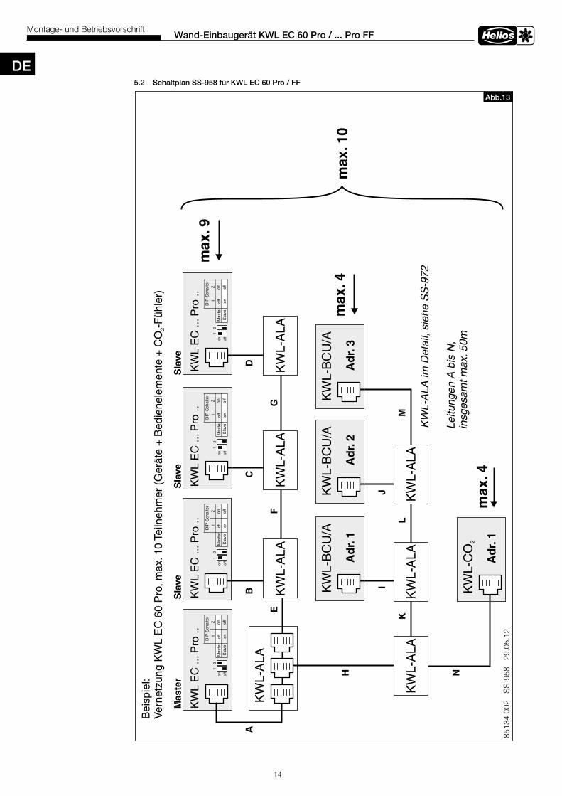
5 .2 Schaltplan SS-958 für KWL EC 60 Pro / FF
14
Wand-Einbaugerät KWL EC 60 Pro / . . . Pro FFMontage- und Betriebsvorschrift
8513
4 00
2 S
S-9
58
29.0
5.12
KW
L-B
CU
/A
Ad
r.1
KW
L E
C ..
.Pro
..
KW
L-A
LA
KW
L-C
O2
max
.4
max
.4A
dr.
1
Bei
spie
l:V
erne
tzun
g K
WL
EC
60
Pro
, max
.10
Teiln
ehm
er (
Ger
äte
+ B
edie
nele
men
te +
CO
-F
ühle
r)2
KW
L-B
CU
/A
Ad
r.2
KW
L-B
CU
/A
Ad
r.3
KW
L-A
LAK
WL-
ALA
KW
L-A
LA
KW
L-A
LAK
WL-
ALA
KW
L-A
LA
AB
CD
EF
G
H
IJ
KL
M
NLe
itung
en A
bis
N,
insg
esam
t max
.50m
KW
L E
C ..
.Pro
..K
WL
EC
...P
ro ..
KW
L E
C ..
.Pro
..
Mas
ter
Sla
veS
lave
Sla
ve
max
.10
KW
L-A
LA im
Det
ail,
sieh
e S
S-9
72
off
on1
2
DIP
-Sch
alte
r1
2M
aste
rof
fon
Sla
veon
off
off
on1
2
DIP
-Sch
alte
r1
2M
aste
rof
fon
Sla
veon
off
off
on1
2
DIP
-Sch
alte
r1
2M
aste
rof
fon
Sla
veon
off
off
on1
2
DIP
-Sch
alte
r1
2M
aste
rof
fon
Sla
veon
off
max
.9
Abb .13
DE
15
Wand-Einbaugerät KWL EC 60 Pro / . . . Pro FFMontage- und Betriebsvorschrift
6 .0 Kondensatableitung Während der Heizperiode kondensiert die Feuchtigkeit der Abluft zu Wasser. Beim Baden, beim Saunieren sowie beim Wäschetrocknen oder bei Neubauten, kann sich reichlich Kondenswasser bilden. Das Kondenswasser muss frei aus dem Gerät ablaufen können. Daher bei Wartungsmaßnahmen, z.B. im Herbst vor Beginn der Heizperiode sicherstellen, dass der Kondenswasserablauf in die Außenfassade ragt und das Kondensat frei ablaufen kann.
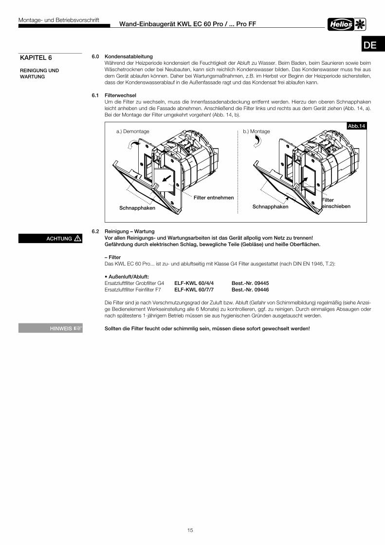
6 .1 Filterwechsel Um die Filter zu wechseln, muss die Innenfassadenabdeckung entfernt werden. Hierzu den oberen Schnapphaken leicht anheben und die Fassade abnehmen. Anschließend die Filter links und rechts aus dem Gerät ziehen (Abb. 14, a). Bei der Montage der Filter umgekehrt vorgehen! (Abb. 14, b).
6 .2 Reinigung – Wartung Vor allen Reinigungs- und Wartungsarbeiten ist das Gerät allpolig vom Netz zu trennen! Gefährdung durch elektrischen Schlag, bewegliche Teile (Gebläse) und heiße Oberflächen .
– Filter Das KWL EC 60 Pro... ist zu- und abluftseitig mit Klasse G4 Filter ausgestattet (nach DIN EN 1946, T.2): • Außenluft/Abluft: Ersatzluftfilter Grobfilter G4 ELF-KWL 60/4/4 Best .-Nr . 09445 Ersatzluftfilter Feinfilter F7 ELF-KWL 60/7/7 Best .-Nr . 09446 Die Filter sind je nach Verschmutzungsgrad der Zuluft bzw. Abluft (Gefahr von Schimmelbildung) regelmäßig (siehe Anzei- ge Bedienelement Werkseinstellung alle 6 Monate) zu kontrollieren, ggf. zu reinigen. Durch einmaliges Absaugen oder nach spätestens 1-jährigem Betrieb müssen sie aus hygienischen Gründen ausgetauscht werden.
Sollten die Filter feucht oder schimmlig sein, müssen diese sofort gewechselt werden!
KAPITEL 6
REINIGUNG UND WARTUNG
ACHTUNG m
HINWEIS +
a.) Demontage b.) Montage
Filter entnehmen
Schnapphaken
FiltereinschiebenSchnapphaken
Abb .14
DE
Helios VentilatorenINSTALLATION AND OPERATING INSTRUCTIONS
Contents
CHAPTER 1 . GENERAL INFORMATION . . . . . . . . . . . . . . . . . . . . . . . . . . . . . . . . . . . . . . . . . . . . . . . . . . . . . . . . . page 11.0 Important information . . . . . . . . . . . . . . . . . . . . . . . . . . . . . . . . . . . . . . . . . . . . . . . . . . . . . . . . . . . . . . . . . . page 11.1 Warning and safety instructions . . . . . . . . . . . . . . . . . . . . . . . . . . . . . . . . . . . . . . . . . . . . . . . . . . . . . . . . . . . page 11.2 Warranty – Exclusion of liability . . . . . . . . . . . . . . . . . . . . . . . . . . . . . . . . . . . . . . . . . . . . . . . . . . . . . . . . . . . page 11.3 Certificates . . . . . . . . . . . . . . . . . . . . . . . . . . . . . . . . . . . . . . . . . . . . . . . . . . . . . . . . . . . . . . . . . . . . . . . . . . page 11.4 Receipt . . . . . . . . . . . . . . . . . . . . . . . . . . . . . . . . . . . . . . . . . . . . . . . . . . . . . . . . . . . . . . . . . . . . . . . . . . . . . page 11.5 Storage . . . . . . . . . . . . . . . . . . . . . . . . . . . . . . . . . . . . . . . . . . . . . . . . . . . . . . . . . . . . . . . . . . . . . . . . . . . . . page 11.6 Application - Operation . . . . . . . . . . . . . . . . . . . . . . . . . . . . . . . . . . . . . . . . . . . . . . . . . . . . . . . . . . . . . . . . . page 11.7 Mode of operation . . . . . . . . . . . . . . . . . . . . . . . . . . . . . . . . . . . . . . . . . . . . . . . . . . . . . . . . . . . . . . . . . . . . . page 11.8 Performance . . . . . . . . . . . . . . . . . . . . . . . . . . . . . . . . . . . . . . . . . . . . . . . . . . . . . . . . . . . . . . . . . . . . . . . . . page 11.9 Fire places. . . . . . . . . . . . . . . . . . . . . . . . . . . . . . . . . . . . . . . . . . . . . . . . . . . . . . . . . . . . . . . . . . . . . . . . . . . page 11.10 Electrical connection . . . . . . . . . . . . . . . . . . . . . . . . . . . . . . . . . . . . . . . . . . . . . . . . . . . . . . . . . . . . . . . . . . . page 21.11 Technical data . . . . . . . . . . . . . . . . . . . . . . . . . . . . . . . . . . . . . . . . . . . . . . . . . . . . . . . . . . . . . . . . . . . . . . . . page 21.12 Accessories . . . . . . . . . . . . . . . . . . . . . . . . . . . . . . . . . . . . . . . . . . . . . . . . . . . . . . . . . . . . . . . . . . . . . . . . . page 2
CHAPTER 2 . SCOPE OF DELIVERY AND PACKING UNIT . . . . . . . . . . . . . . . . . . . . . . . . . . . . . . . . . . . . . . . . . . page 22.0 Scope of delivery / packing unit . . . . . . . . . . . . . . . . . . . . . . . . . . . . . . . . . . . . . . . . . . . . . . . . . . . . . . . . . . page 2
CHAPTER 3 . INSTALLATION . . . . . . . . . . . . . . . . . . . . . . . . . . . . . . . . . . . . . . . . . . . . . . . . . . . . . . . . . . . . . . . . . . page 33.0 Wall installation KWL 60 RS First fix set . . . . . . . . . . . . . . . . . . . . . . . . . . . . . . . . . . . . . . . . . . . . . . . . . . . . . page 33.1 Laying of control and mains supply cable . . . . . . . . . . . . . . . . . . . . . . . . . . . . . . . . . . . . . . . . . . . . . . . . . . . page 33.2 Installation of KWL EC 60 fan unit . . . . . . . . . . . . . . . . . . . . . . . . . . . . . . . . . . . . . . . . . . . . . . . . . . . . . . . . . page 33.3 Installation of KWL 60 WV extension sleeve . . . . . . . . . . . . . . . . . . . . . . . . . . . . . . . . . . . . . . . . . . . . . . . . . . page 33.4 Installation of KWL 60 DR compensation ring . . . . . . . . . . . . . . . . . . . . . . . . . . . . . . . . . . . . . . . . . . . . . . . . page 4
CHAPTER 4 . COMFORT CONTROLLER KWL-BCU/KWL-BCA . . . . . . . . . . . . . . . . . . . . . . . . . . . . . . . . . . . . . . page 44.0 Functional description to menu tree. . . . . . . . . . . . . . . . . . . . . . . . . . . . . . . . . . . . . . . . . . . . . . . . . . . . . . . . page 44.1 Comfort controller KWL 60 BC.. . . . . . . . . . . . . . . . . . . . . . . . . . . . . . . . . . . . . . . . . . . . . . . . . . . . . . . . . . . page 64.2 Operating menu . . . . . . . . . . . . . . . . . . . . . . . . . . . . . . . . . . . . . . . . . . . . . . . . . . . . . . . . . . . . . . . . . . . . . . page 64.3 Error menu/Error message in the display . . . . . . . . . . . . . . . . . . . . . . . . . . . . . . . . . . . . . . . . . . . . . . . . . . . page 124.4 Chart: Weekly program . . . . . . . . . . . . . . . . . . . . . . . . . . . . . . . . . . . . . . . . . . . . . . . . . . . . . . . . . . . . . . . . page 12
CHAPTER 5 . ELECTRICAL CONNECTION . . . . . . . . . . . . . . . . . . . . . . . . . . . . . . . . . . . . . . . . . . . . . . . . . . . . . . page 135.0 Electrical connection . . . . . . . . . . . . . . . . . . . . . . . . . . . . . . . . . . . . . . . . . . . . . . . . . . . . . . . . . . . . . . . . . . page 135.1 Wiring diagram SS-950 . . . . . . . . . . . . . . . . . . . . . . . . . . . . . . . . . . . . . . . . . . . . . . . . . . . . . . . . . . . . . . . . page 135.2 Wiring diagram SS-958 . . . . . . . . . . . . . . . . . . . . . . . . . . . . . . . . . . . . . . . . . . . . . . . . . . . . . . . . . . . . . . . . page 14
CHAPTER 6 . CLEANING AND MAINTENANCE . . . . . . . . . . . . . . . . . . . . . . . . . . . . . . . . . . . . . . . . . . . . . . . . . . page 156.0 Condensate removal . . . . . . . . . . . . . . . . . . . . . . . . . . . . . . . . . . . . . . . . . . . . . . . . . . . . . . . . . . . . . . . . . . page 156.1 Service . . . . . . . . . . . . . . . . . . . . . . . . . . . . . . . . . . . . . . . . . . . . . . . . . . . . . . . . . . . . . . . . . . . . . . . . . . . . page 156.2 Cleaning – Maintenance . . . . . . . . . . . . . . . . . . . . . . . . . . . . . . . . . . . . . . . . . . . . . . . . . . . . . . . . . . . . . . . page 15
Correct Disposal of This Product (Waste Electrical & Electronic Equipment)(Applicable in the European Union and other European countries with separate collection systems)This marking shown on the product or its Operation and Installation Instruction, indicates that it should not be disposed with other household wastes at the end of its working life. To prevent possible harm to the environment or human health from uncontrolled waste disposal, please separate this from other types of wastes and recycle it responsibly to promote the sustainable reuse of material resources.Household users should contact either the retailer where they purchased this product, or their local government office, for details of where and how they can take this item for environmentally safe recycling.Business users should contact their supplier and check the terms and conditions of the purchase contract.This product should not be mixed with other commercial wastes for disposal.
ENGLISH
TIP!
1
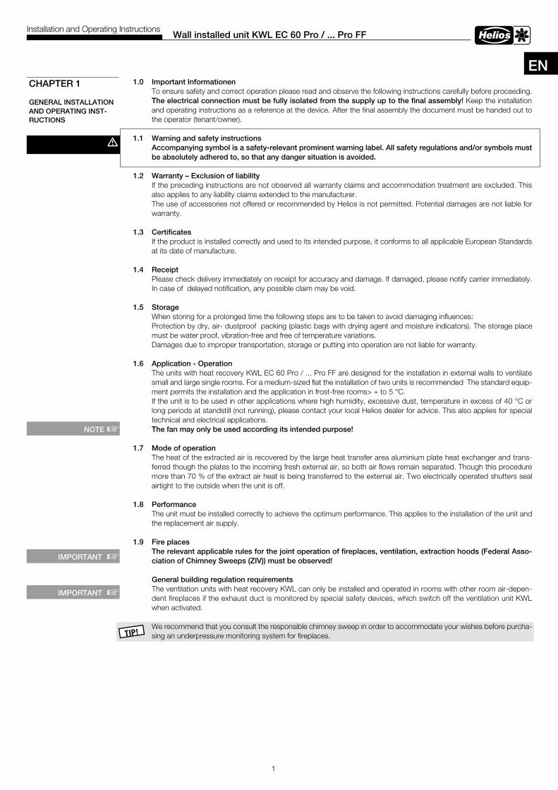
1 .0 Important InformationenTo ensure safety and correct operation please read and observe the following instructions carefully before proceeding. The electrical connection must be fully isolated from the supply up to the final assembly! Keep the installation and operating instructions as a reference at the device. After the final assembly the document must be handed out to the operator (tenant/owner).
1 .1 Warning and safety instructionsAccompanying symbol is a safety-relevant prominent warning label . All safety regulations and/or symbols must be absolutely adhered to, so that any danger situation is avoided .
1 .2 Warranty – Exclusion of liability If the preceding instructions are not observed all warranty claims and accommodation treatment are excluded. This also applies to any liability claims extended to the manufacturer.The use of accessories not offered or recommended by Helios is not permitted. Potential damages are not liable for warranty.
1 .3 CertificatesIf the product is installed correctly and used to its intended purpose, it conforms to all applicable European Standards at its date of manufacture.
1 .4 ReceiptPlease check delivery immediately on receipt for accuracy and damage. If damaged, please notify carrier immediately. In case of delayed notification, any possible claim may be void.
1 .5 StorageWhen storing for a prolonged time the following steps are to be taken to avoid damaging influences:Protection by dry, air- dustproof packing (plastic bags with drying agent and moisture indicators). The storage place must be water proof, vibration-free and free of temperature variations.Damages due to improper transportation, storage or putting into operation are not liable for warranty.
1 .6 Application - Operation The units with heat recovery KWL EC 60 Pro / ... Pro FF are designed for the installation in external walls to ventilate small and large single rooms. For a medium-sized flat the installation of two units is recommended The standard equip-ment permits the installation and the application in frost-free rooms> + to 5 °C.If the unit is to be used in other applications where high humidity, excessive dust, temperature in excess of 40 °C or long periods at standstill (not running), please contact your local Helios dealer for advice. This also applies for special technical and electrical applications. The fan may only be used according its intended purpose!
1 .7 Mode of operationThe heat of the extracted air is recovered by the large heat transfer area aluminium plate heat exchanger and trans-ferred though the plates to the incoming fresh external air, so both air flows remain separated. Though this procedure more than 70 % of the extract air heat is being transferred to the external air. Two electrically operated shutters seal airtight to the outside when the unit is off.
1 .8 PerformanceThe unit must be installed correctly to achieve the optimum performance. This applies to the installation of the unit and the replacement air supply.
1 .9 Fire places The relevant applicable rules for the joint operation of fireplaces, ventilation, extraction hoods (Federal Asso-ciation of Chimney Sweeps (ZIV)) must be observed!
General building regulation requirementsThe ventilation units with heat recovery KWL can only be installed and operated in rooms with other room air-depen-dent fireplaces if the exhaust duct is monitored by special safety devices, which switch off the ventilation unit KWL when activated.
We recommend that you consult the responsible chimney sweep in order to accommodate your wishes before purcha-sing an underpressure monitoring system for fireplaces.
Wall installed unit KWL EC 60 Pro / . . . Pro FFInstallation and Operating Instructions
CHAPTER 1
GENERAL INSTALLATION AND OPERATING INST-RUCTIONS
m
NOTE +
EN
IMPORTANT +
IMPORTANT +
KWL 60 WV
2
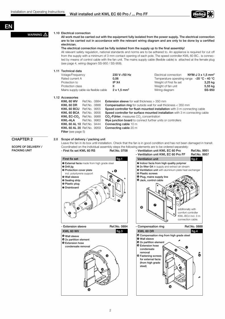
1 .10 Electrical connectionAll work must be carried out with the equipment fully isolated from the power supply . The electrical connection are to be carried out in accordance with the relevant wiring diagram and are only to be done by a certified electrician .The electrical connection must be fully isolated from the supply up to the final assembly!All relevant safety regulation, national standards and norms are to be adhered to. An appliance is required for cut off from the supply with a minimum of 3 mm contact opening of each pole. The speed controller KWL 60 BC.. is connec-ted by means of control cable with the fan unit. The mains supply cable (flexible cable) is attached at the female plug (see page 4, wiring diagram SS-950 / SS-958).
1 .11 Technical dataVotage/Frequency 230 V~/50 Hz Electrical connection NYM-J 3 x 1,5 mm2
Rated current A 0,06 Temperature operating range -20 °C - 40 °CProtection to IP X4 Weight of First fix set 3,25 kgProtection class II Weight of fan unit 5,55 kgMains supply cable via flexible cable 2 x 1,5 mm2 Wiring diagram SS-950
1 .12 Accessories KWL 60 WV Ref.No. 0884 Extension sleeve for wall thickness > 350 mm KWL 60 DR Ref.No. 0888 Compensation ring for outside wall for wall thickness < 350 mm KWL 60 BCU Ref.No. 9955 Speed controller for flush mounted installation with 3 m connecting cable KWL 60 BCA Ref.No. 9956 Speed controller for surface mounted installation with 3 m connecting cable KWL EC-CO2 Ref.No. 9988 CO2-Fühler, measures CO2 concentration KWL-ALA Ref.No. 9960 Wye junction board to connect further units or controllers KWL 60 AL 10 Ref.No. 9444 Connecting cable 10 m KWL 60 AL 20 Ref.No. 9959 Connecting cable 20 m Filter (see page 5) 2 .0 Scope of delivery / packing unit
Leave the fan in its box until installation. Check that the fan is in good condition and has not been damaged in transit.Coordinated on the individual assembly steps the following elements are to be ordered separately:- First fix set KWL 60 RS Ref .No . 0708 - Ventilation unit KWL EC 60 Pro Ref .No . 9951 - Ventilation unit KWL EC 60 Pro FF Ref .No . 9957
- Extension sleeve Ref .No . 0884 - Compensation ring Ref .No . 0888
fig .3 KWL 60 DR fig .4
20
18
Wall installed unit KWL EC 60 Pro / . . . Pro FFInstallation and Operating Instructions
First fix set
ë
ò
fig .1
ù
CHAPTER 2
SCOPE OF DELIVERY / PACKING UNIT
ä
WARNING m
Ventilation unit
ö
fig .2
Å
î
ä
ä
ä
Ø
Æ
11
12
ü
ò External facia made from high grade steelù Drill jigä Protection cover plate incl. polystyrene supportë Wall sleeve ö Sealing stripü Plastic plugÅ Drainboard
Å Indoor facia from high quality polymerî 2x filter G4 in supply and extract air streamØ Ventilation unit with aluminium plate heat exchanger Æ Plastic screws Plug, mains supply line Jack, control cable
Wall sleeve2x partition elementExtension hosecondensate removal
Compensation ring from high grade steelWall sleeve2x partition element Extension hose condensate removalFastening screwsfor external facia(from high gradesteel)
11
12
19
17
16
16
17
18
19
20
13
14
15
14
15
13
EN
additionally withcomfort controllerKWL-BCU incl. 3 m connection cable.
Å
3
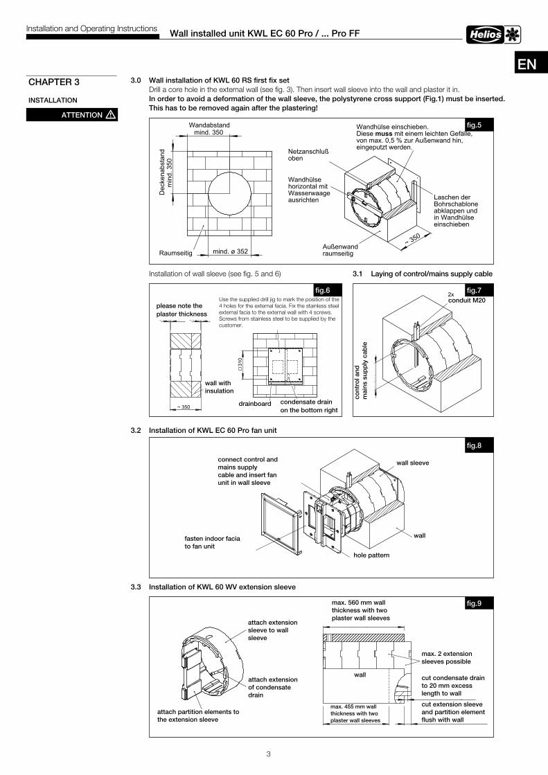
3 .0 Wall installation of KWL 60 RS first fix set Drill a core hole in the external wall (see fig. 3). Then insert wall sleeve into the wall and plaster it in. In order to avoid a deformation of the wall sleeve, the polystyrene cross support (Fig .1) must be inserted . This has to be removed again after the plastering!
Installation of wall sleeve (see fig. 5 and 6) 3 .1 Laying of control/mains supply cable
3 .2 Installation of KWL EC 60 Pro fan unit
3 .3 Installation of KWL 60 WV extension sleeve
Wall installed unit KWL EC 60 Pro / . . . Pro FFInstallation and Operating Instructions
CHAPTER 3
INSTALLATION
beachtenPutzstärke
beachtenPutzstärke
~ 350
Wand mitIsolierung
310
Bohrbild mittels Schablone abbohren.Edelstahlfassade und Abtropfblechan der Außenwand befestigen.(Befestigungsschrauben aus Edelstahlbauseits)
Kondensatablaufrechts unten
Abtropfblech
fig .6
ca. 2
00 m
m
Ste
uer.-
und
Net
zzul
eitu
ng
2xLeerrohr M20
fig .7
Trennsteg auf das Gehäuseder Lüftungseinheit aufstecken
Wandring aufWandhülseaufstecken
VerlängerungKondensatablaufaufstecken
fig .9max. 560 mm
Wanddicke bei zweiVerlängerungshülsen
(Putzstärke beachten)
Wandring und Trennstegwandbündig abschneiden
mit 20 mm Überstandzur Wand ablängen
Kondensatablauf
max. 455 mmWanddicke bei einerVerlängerungshülse
max. 2 Wandhülsen-Verlängerungen
Wand
Wand
WandhülseNetz.- und Steuerleitunganschließen und denLüftungseinsatz in dieWandhülse einschieben
Bohrbild abbohren
Kunststofffassade ander Innenwand bzw.am Lüftungseinsatzbefestigen.
fig .8
ATTENTION m
EN
distance to wall
dis
tanc
e to
cei
ling
room-sided
mains supply above
external wall room-sided
Insert and plaster wall sleeve . Decline 0,5 %
swing out latches of the drill jig and insert in wall sleeve
align wallsleeve with spirit level
cont
rol a
nd
mai
ns s
upp
ly c
able
conduit M20
wall with insulation
wall sleeve
wall
connect control andmains supplycable and insert fanunit in wall sleeve
fasten indoor facia to fan unit
attach extension sleeve to wall sleeve
attach extension of condensate drain
attach partition elements to the extension sleeve
wall
max . 2 extension sleeves possible
cut condensate drain to 20 mm excess length to wall
cut extension sleeve and partition element flush with wall
condensate drainon the bottom right
Use the supplied drill jig to mark the position of the 4 holes for the external facia. Fix the stainless steel external facia to the external wall with 4 screws. Screws from stainless steel to be supplied by the customer.
please note the plaster thickness
drainboard
mind. 350Wandabstand
min
d. 3
50D
ecke
nabs
tand
mind. ø 352Raumseitig~ 350
Wandhülse einschieben.Diese muss mit einem leichten Gefälle,von max. 0,5 % zur Außenwand hin,eingeputzt werden.
Außenwandraumseitig
Wandhülsehorizontal mitWasserwaageausrichten
Netzanschlußoben
Laschen derBohrschabloneabklappen undin Wandhülseeinschieben
fig .5
hole pattern
max . 560 mm wall thickness with two plaster wall sleeves
max . 455 mm wall thickness with two plaster wall sleeves
4
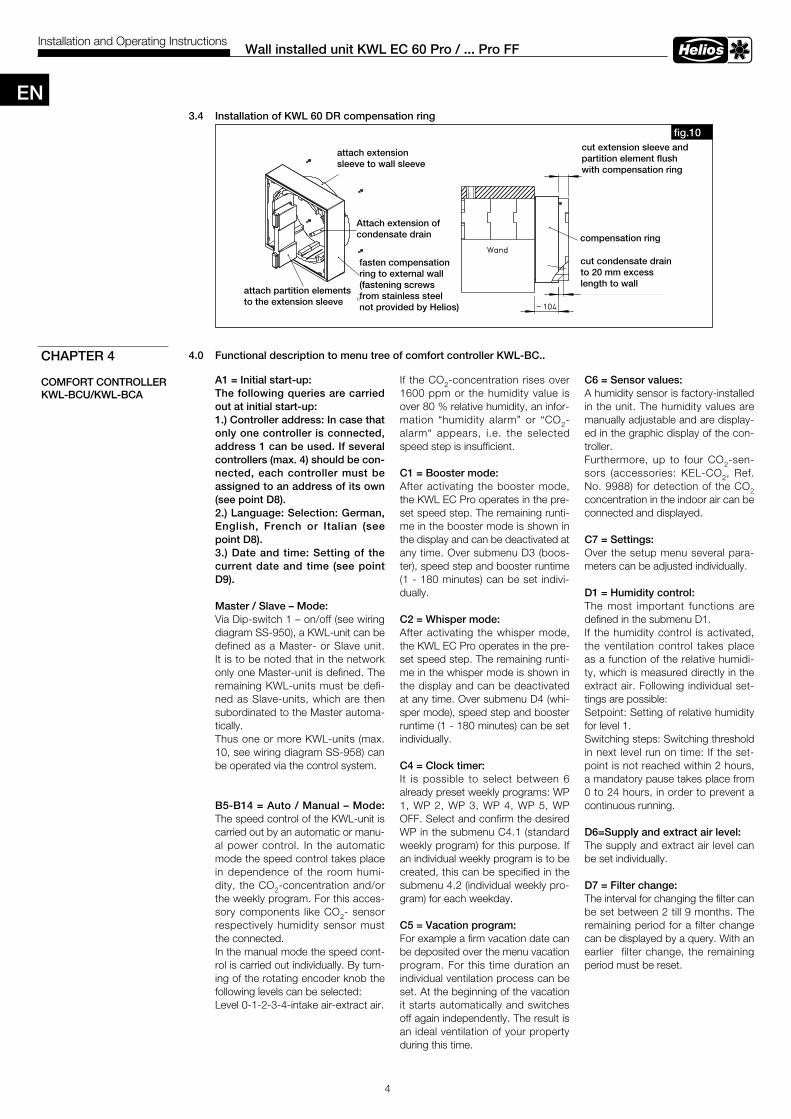
3 .4 Installation of KWL 60 DR compensation ring
4 .0 Functional description to menu tree of comfort controller KWL-BC . .
Wall installed unit KWL EC 60 Pro / . . . Pro FFInstallation and Operating Instructions
CHAPTER 4
COMFORT CONTROLLER KWL-BCU/KWL-BCA
SS-932Trennsteg auf das Gehäuse
der Lüftungseinheit aufstecken
VerlängerungKondensatablaufaufstecken
Wandring aufWandhülseaufstecken
Distanzrahmen an derAußenwand befestigen(Befestigungsschraubenaus Edelstahl bauseits)
fig .10
abschneiden
Wandring und Trennstegbündig mit Distanzrahmen
~ 104
mit 20 mm Überstandzum Distanzrahmenablängen
KondensatablaufWand
Distanzrahmen
attach extension sleeve to wall sleeve
Attach extension of condensate drain
fasten compensation ring to external wall (fastening screws from stainless steel not provided by Helios)
attach partition elementsto the extension sleeve
cut extension sleeve andpartition element flush with compensation ring
compensation ring
cut condensate drainto 20 mm excess length to wall
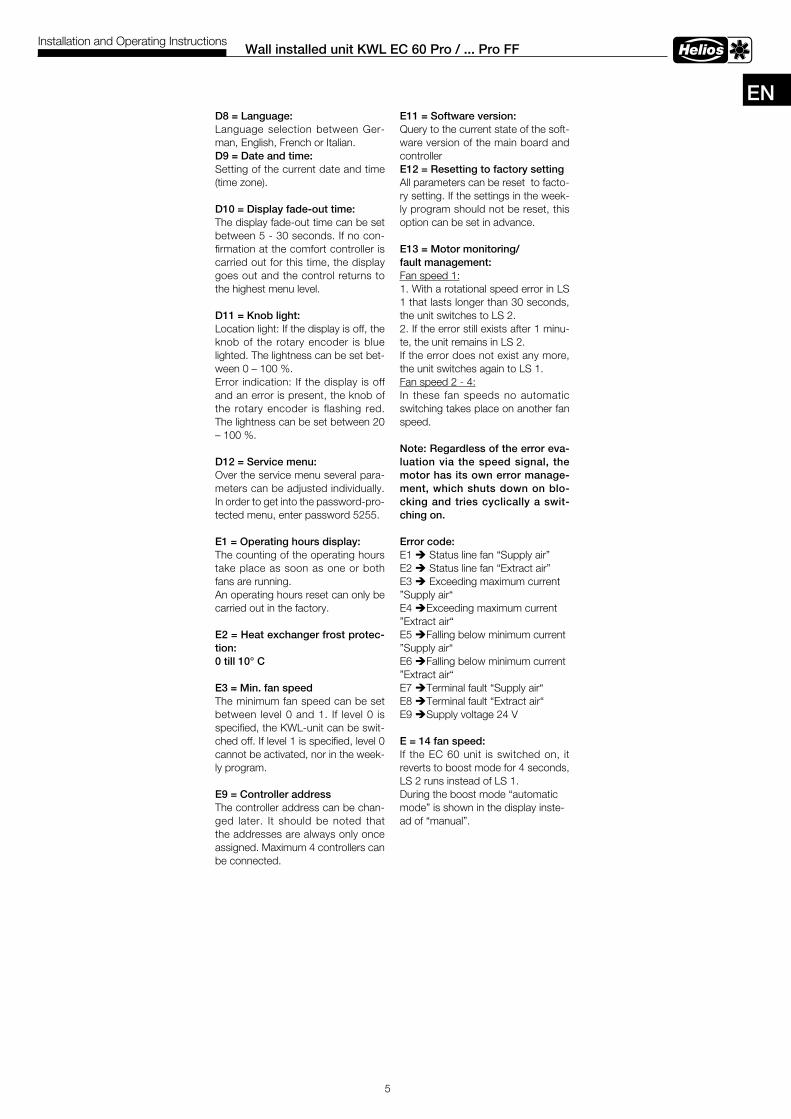
A1 = Initial start-up:The following queries are carried out at initial start-up:1 .) Controller address: In case that only one controller is connected, address 1 can be used . If several controllers (max . 4) should be con-nected, each controller must be assigned to an address of its own (see point D8) .2 .) Language: Selection: German, English, French or Italian (see point D8) .3 .) Date and time: Setting of the current date and time (see point D9) .
Master / Slave – Mode:Via Dip-switch 1 – on/off (see wiring diagram SS-950), a KWL-unit can be defined as a Master- or Slave unit. It is to be noted that in the network only one Master-unit is defined. The remaining KWL-units must be defi-ned as Slave-units, which are then subordinated to the Master automa-tically. Thus one or more KWL-units (max. 10, see wiring diagram SS-958) can be operated via the control system.
B5-B14 = Auto / Manual – Mode: The speed control of the KWL-unit is carried out by an automatic or manu-al power control. In the automatic mode the speed control takes place in dependence of the room humi-dity, the CO2-concentration and/or the weekly program. For this acces-sory components like CO2- sensor respectively humidity sensor must the connected.In the manual mode the speed cont-rol is carried out individually. By turn-ing of the rotating encoder knob the following levels can be selected:Level 0-1-2-3-4-intake air-extract air.
If the CO2-concentration rises over 1600 ppm or the humidity value is over 80 % relative humidity, an infor-mation “humidity alarm” or “CO2-alarm“ appears, i.e. the selected speed step is insufficient.
C1 = Booster mode:After activating the booster mode, the KWL EC Pro operates in the pre-set speed step. The remaining runti-me in the booster mode is shown in the display and can be deactivated at any time. Over submenu D3 (boos-ter), speed step and booster runtime (1 - 180 minutes) can be set indivi-dually.
C2 = Whisper mode:After activating the whisper mode, the KWL EC Pro operates in the pre-set speed step. The remaining runti-me in the whisper mode is shown in the display and can be deactivated at any time. Over submenu D4 (whi-sper mode), speed step and booster runtime (1 - 180 minutes) can be set individually.
C4 = Clock timer:It is possible to select between 6 already preset weekly programs: WP 1, WP 2, WP 3, WP 4, WP 5, WP OFF. Select and confirm the desired WP in the submenu C4.1 (standard weekly program) for this purpose. If an individual weekly program is to be created, this can be specified in the submenu 4.2 (individual weekly pro-gram) for each weekday.
C5 = Vacation program:For example a firm vacation date can be deposited over the menu vacation program. For this time duration an individual ventilation process can be set. At the beginning of the vacation it starts automatically and switches off again independently. The result is an ideal ventilation of your property during this time.
C6 = Sensor values:A humidity sensor is factory-installed in the unit. The humidity values are manually adjustable and are display-ed in the graphic display of the con-troller.Furthermore, up to four CO2-sen-sors (accessories: KEL-CO2, Ref.No. 9988) for detection of the CO2 concentration in the indoor air can be connected and displayed.
C7 = Settings:Over the setup menu several para-meters can be adjusted individually.
D1 = Humidity control:The most important functions are defined in the submenu D1.If the humidity control is activated, the ventilation control takes place as a function of the relative humidi-ty, which is measured directly in the extract air. Following individual set-tings are possible:Setpoint: Setting of relative humidity for level 1.Switching steps: Switching threshold in next level run on time: If the set-point is not reached within 2 hours, a mandatory pause takes place from 0 to 24 hours, in order to prevent a continuous running.
D6=Supply and extract air level:The supply and extract air level can be set individually.
D7 = Filter change:The interval for changing the filter can be set between 2 till 9 months. The remaining period for a filter change can be displayed by a query. With an earlier filter change, the remaining period must be reset.
EN
5
Wall installed unit KWL EC 60 Pro / . . . Pro FFInstallation and Operating Instructions
D8 = Language:Language selection between Ger-man, English, French or Italian.D9 = Date and time: Setting of the current date and time (time zone). D10 = Display fade-out time:The display fade-out time can be set between 5 - 30 seconds. If no con-firmation at the comfort controller is carried out for this time, the display goes out and the control returns to the highest menu level.
D11 = Knob light:Location light: If the display is off, the knob of the rotary encoder is blue lighted. The lightness can be set bet-ween 0 – 100 %.Error indication: If the display is off and an error is present, the knob of the rotary encoder is flashing red. The lightness can be set between 20 – 100 %.
D12 = Service menu:Over the service menu several para-meters can be adjusted individually. In order to get into the password-pro-tected menu, enter password 5255.
E1 = Operating hours display:The counting of the operating hours take place as soon as one or both fans are running.An operating hours reset can only be carried out in the factory.
E2 = Heat exchanger frost protec-tion:0 till 10° C
E3 = Min . fan speedThe minimum fan speed can be set between level 0 and 1. If level 0 is specified, the KWL-unit can be swit-ched off. If level 1 is specified, level 0 cannot be activated, nor in the week-ly program.
E9 = Controller addressThe controller address can be chan-ged later. It should be noted that the addresses are always only once assigned. Maximum 4 controllers can be connected.
E11 = Software version: Query to the current state of the soft-ware version of the main board and controllerE12 = Resetting to factory settingAll parameters can be reset to facto-ry setting. If the settings in the week-ly program should not be reset, this option can be set in advance.
E13 = Motor monitoring/fault management:Fan speed 1:1. With a rotational speed error in LS 1 that lasts longer than 30 seconds, the unit switches to LS 2.2. If the error still exists after 1 minu-te, the unit remains in LS 2. If the error does not exist any more, the unit switches again to LS 1. Fan speed 2 - 4:In these fan speeds no automatic switching takes place on another fan speed.
Note: Regardless of the error eva-luation via the speed signal, the motor has its own error manage-ment, which shuts down on blo-cking and tries cyclically a swit-ching on .
Error code:E1 è Status line fan “Supply air” E2 è Status line fan “Extract air” E3 è Exceeding maximum current ”Supply air“E4 èExceeding maximum current ”Extract air“E5 èFalling below minimum current ”Supply air“E6 èFalling below minimum current ”Extract air“E7 èTerminal fault “Supply air“E8 èTerminal fault “Extract air“E9 èSupply voltage 24 V
E = 14 fan speed:If the EC 60 unit is switched on, it reverts to boost mode for 4 seconds, LS 2 runs instead of LS 1.During the boost mode “automatic mode” is shown in the display inste-ad of “manual”.
EN
6
Wall installed unit KWL EC 60 Pro / . . . Pro FFInstallation and Operating Instructions
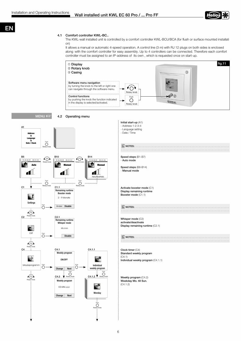
4 .1 Comfort controller KWL-BC . . The KWL-wall installed unit is controlled by a comfort controller KWL-BCU/BCA (for flush or surface mounted installati on) It allows a manual or automatic 4-speed operation. A control line (3 m) with RJ 12 plugs on both sides is enclosed along with the comfort controller for easy assembly. Up to 4 controllers can be connected. Therefore each comfort controller must be assigned to an IP-address of its own , which is requested once on start-up.
4 .2 Operating menu
â
ê
ô
â Displayê Rotary knob ô Casing
Software menu navigation by turning the knob to the left or right one can navigate through the software menu.
Control functionsby pushing the knob the function indicated in the display is selected/activated.
Initial start-up (A1)- Address 1-2-3-4- Language setting- Date / Time
Speed steps (B1-B7) - Auto mode Speed steps (B8-B14) - Manual mode
Activate booster mode (C1)Display remaining runtime Booster mode (C1.1)
Whisper mode (C2) activate/deactivate Display remaining runtime (C2.1)
Clock timer (C4)Standard weekly program (C4.1)Individual weekly program (C4.1.1)
Weekly program (C4.2)Weekday Mo . till Sun . (C4.1.2)
MENU +
�NOTES: . . . . . . . . . . . . . . . . . . . . . . . . . . . . . . . . . . . . . . . . . . . . . . . . . . . . . . . . . . . . . . . . . . . . . . . . . . . . . . . . . . . . . . . . . . . . . . . . . . . . . . . . . . . . . . . . . . . . . . . . . . . . . . . . . . . . . . . . . . .
�NOTES: . . . . . . . . . . . . . . . . . . . . . . . . . . . . . . . . . . . . . . . . . . . . . . . . . . . . . . . . . . . . . . . . . . . . . . . . . . . . . . . . . . . . . . . . . . . . . . . . . . . . . . . . . . . . . . . . . . . . . . . . . . . . . . . . . . . . . . . . . . .
A1
C1 C1 .1
B5 B10 B14
C2 C2 .1
C4 C4 .1
C4 .2
C4 .1 .1
�NOTES: . . . . . . . . . . . . . . . . . . . . . . . . . . . . . . . . . . . . . . . . . . . . . . . . . . . . . . . . . . . . . . . . . . . . . . . . . . . . . . . . . . . . . . . . . . . . . . . . . . . . . . . . . . . . . . . . . . . . . . . . . . . . . . . . . . . . . . . . . . .
C4 .1 .2
fig .11
Address&
Language&
Date / Clock
Rotary knob
Rotary knob
Manual ManualAuto
Settings
Remaining runtimeBooster mode
Remaining runtimeWhisper mode
Disable
Disable
Weekly program
Individualweekly program
Monday
ON/OFF
Change Next
Change Next
Weekly program
EN
7
Wall installed unit KWL EC 60 Pro / . . . Pro FFInstallation and Operating Instructions
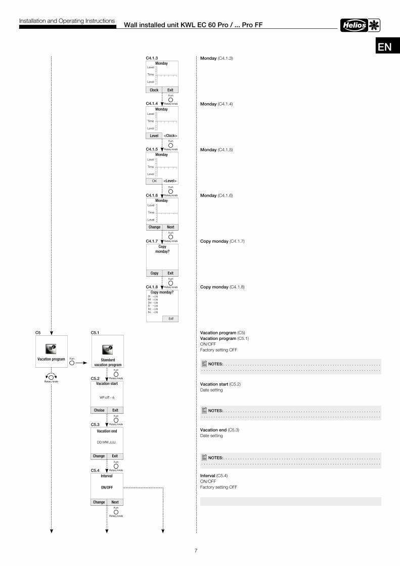
Monday (C4.1.3)
Monday (C4.1.4)
Monday (C4.1.5)
Monday (C4.1.6)
Copy monday (C4.1.7)
Copy monday (C4.1.8)
Vacation program (C5) Vacation program (C5.1)ON/OFFFactory setting OFF
Vacation start (C5.2) Date setting
Vacation end (C5.3) Date setting
Interval (C5.4)ON/OFFFactory setting OFF
C5 C5 .1
C4 .1 .3
C5 .2
C5 .3
C5 .4
C4 .1 .4
C4 .1 .5
C4 .1 .6
C4 .1 .7
C4 .1 .8
�NOTES: . . . . . . . . . . . . . . . . . . . . . . . . . . . . . . . . . . . . . . . . . . . . . . . . . . . . . . . . . . . . . . . . . . . . . . . . . . . . . . . . . . . . . . . . . . . . . . . . . . . . . . . . . . . . . . . . . . . . . . . . . . . . . . . . . . . . . . . . . . .
�NOTES: . . . . . . . . . . . . . . . . . . . . . . . . . . . . . . . . . . . . . . . . . . . . . . . . . . . . . . . . . . . . . . . . . . . . . . . . . . . . . . . . . . . . . . . . . . . . . . . . . . . . . . . . . . . . . . . . . . . . . . . . . . . . . . . . . . . . . . . . . . .
�NOTES: . . . . . . . . . . . . . . . . . . . . . . . . . . . . . . . . . . . . . . . . . . . . . . . . . . . . . . . . . . . . . . . . . . . . . . . . . . . . . . . . . . . . . . . . . . . . . . . . . . . . . . . . . . . . . . . . . . . . . . . . . . . . . . . . . . . . . . . . . . .
Clock Exit
Monday
Monday
Monday
Monday
Level <Clock>
Level
Time
Level
Level
Time
Level
Level
Time
Level
<Level>
Change Next
Copy Exit
Copy monday?
Copy monday?
Level
Time
Level
Standardvacation program
Choise Exit
Change Exit
Vacation start
Vacation program
Vacation end
Interval
ON/OFF
Change Next
EN
8
Wall installed unit KWL EC 60 Pro / . . . Pro FFInstallation and Operating Instructions
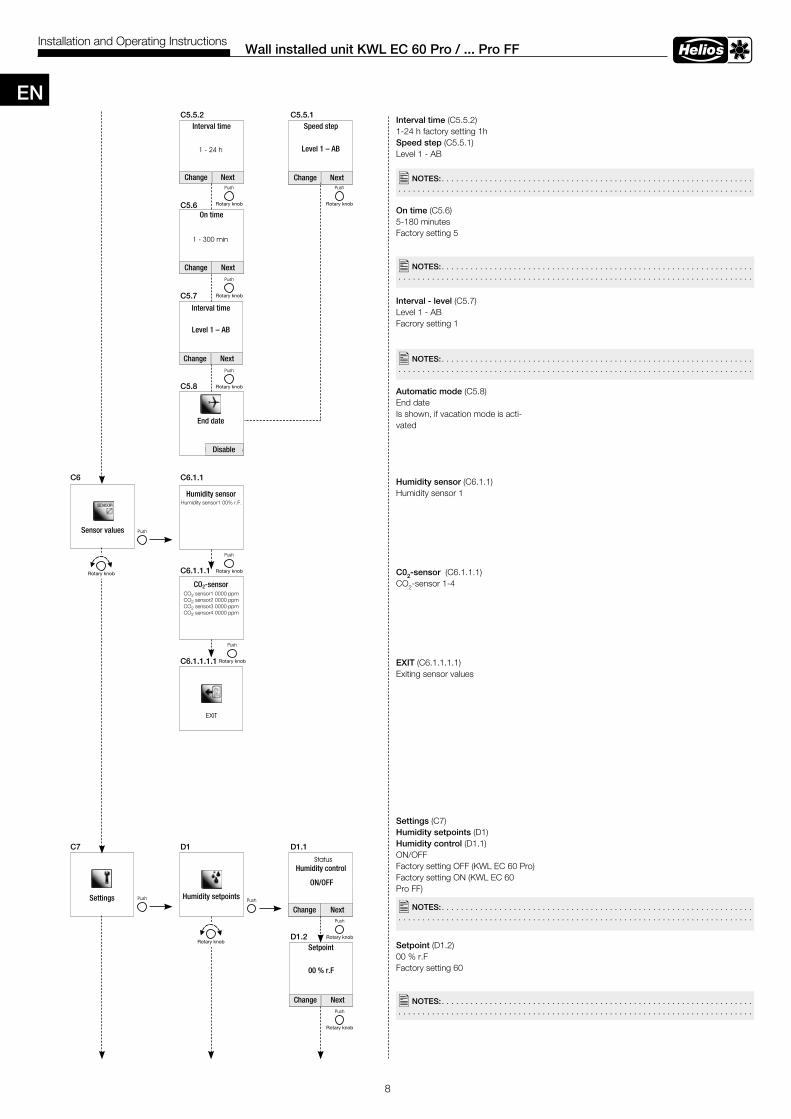
Interval time (C5.5.2)1-24 h factory setting 1hSpeed step (C5.5.1)Level 1 - AB
On time (C5.6)5-180 minutesFactory setting 5
Interval - level (C5.7)Level 1 - ABFacrory setting 1
Automatic mode (C5.8)End date Is shown, if vacation mode is acti-vated
Humidity sensor (C6.1.1)Humidity sensor 1
C02-sensor (C6.1.1.1)CO2-sensor 1-4
EXIT (C6.1.1.1.1)Exiting sensor values
Settings (C7)Humidity setpoints (D1)Humidity control (D1.1)ON/OFFFactory setting OFF (KWL EC 60 Pro)Factory setting ON (KWL EC 60 Pro FF)
Setpoint (D1.2)00 % r.F Factory setting 60
C5 .5 .2 C5 .5 .1
C5 .6
C5 .7
C5 .8
�NOTES: . . . . . . . . . . . . . . . . . . . . . . . . . . . . . . . . . . . . . . . . . . . . . . . . . . . . . . . . . . . . . . . . . . . . . . . . . . . . . . . . . . . . . . . . . . . . . . . . . . . . . . . . . . . . . . . . . . . . . . . . . . . . . . . . . . . . . . . . . . .
C6 C6 .1 .1
C6 .1 .1 .1
C6 .1 .1 .1 .1
C7 D1 D1 .1
D1 .2
�NOTES: . . . . . . . . . . . . . . . . . . . . . . . . . . . . . . . . . . . . . . . . . . . . . . . . . . . . . . . . . . . . . . . . . . . . . . . . . . . . . . . . . . . . . . . . . . . . . . . . . . . . . . . . . . . . . . . . . . . . . . . . . . . . . . . . . . . . . . . . . . .
�NOTES: . . . . . . . . . . . . . . . . . . . . . . . . . . . . . . . . . . . . . . . . . . . . . . . . . . . . . . . . . . . . . . . . . . . . . . . . . . . . . . . . . . . . . . . . . . . . . . . . . . . . . . . . . . . . . . . . . . . . . . . . . . . . . . . . . . . . . . . . . . .
�NOTES: . . . . . . . . . . . . . . . . . . . . . . . . . . . . . . . . . . . . . . . . . . . . . . . . . . . . . . . . . . . . . . . . . . . . . . . . . . . . . . . . . . . . . . . . . . . . . . . . . . . . . . . . . . . . . . . . . . . . . . . . . . . . . . . . . . . . . . . . . . .
�NOTES: . . . . . . . . . . . . . . . . . . . . . . . . . . . . . . . . . . . . . . . . . . . . . . . . . . . . . . . . . . . . . . . . . . . . . . . . . . . . . . . . . . . . . . . . . . . . . . . . . . . . . . . . . . . . . . . . . . . . . . . . . . . . . . . . . . . . . . . . . . .
Interval time Speed step
On time
Interval time
End date
Level 1 – AB
Change Next
Change Next
Change Next Change Next
Change Next
Change Next
Level 1 – AB
Disable
Humidity sensor
CO2-sensor
Humidity control
ON/OFF
Setpoint
00 % r.F
Humidity setpointsSettings
Sensor values
Humidity sensor1 00% r.F.
CO2 sensor1 0000 ppmCO2 sensor2 0000 ppmCO2 sensor3 0000 ppmCO2 sensor4 0000 ppm
EN
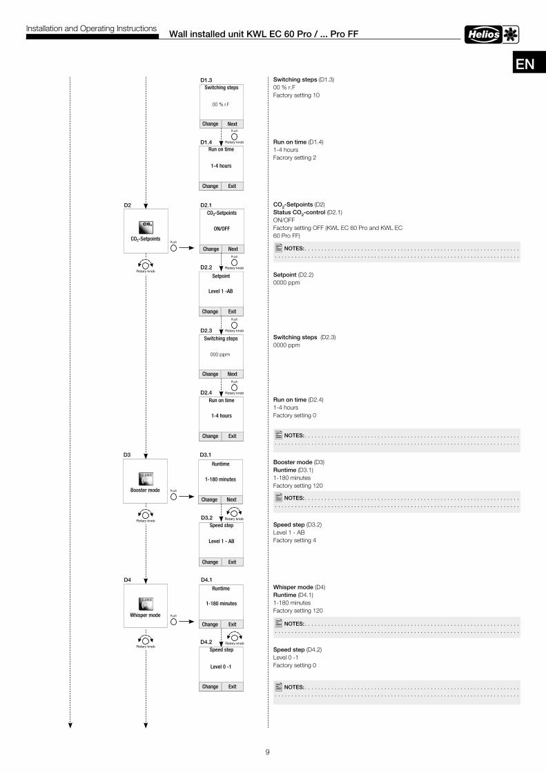
9
Wall installed unit KWL EC 60 Pro / . . . Pro FFInstallation and Operating Instructions
Switching steps (D1.3)00 % r.FFactory setting 10
Run on time (D1.4)1-4 hoursFacrory setting 2
CO2-Setpoints (D2)Status CO2-control (D2.1)ON/OFF Factory setting OFF (KWL EC 60 Pro and KWL EC 60 Pro FF)
Setpoint (D2.2)0000 ppm
Switching steps (D2.3)0000 ppm
Run on time (D2.4) 1-4 hoursFactory setting 0
Booster mode (D3)Runtime (D3.1)1-180 minutesFactory setting 120
Speed step (D3.2)Level 1 - ABFactory setting 4
Whisper mode (D4)Runtime (D4.1)1-180 minutesFactory setting 120
Speed step (D4.2)Level 0 -1 Factory setting 0
D1 .3
D1 .4
D2 D2 .1
D3 D3 .1
D2 .2
D2 .3
D2 .4
D4 .2
D3 .2
D4 .1D4
�NOTES: . . . . . . . . . . . . . . . . . . . . . . . . . . . . . . . . . . . . . . . . . . . . . . . . . . . . . . . . . . . . . . . . . . . . . . . . . . . . . . . . . . . . . . . . . . . . . . . . . . . . . . . . . . . . . . . . . . . . . . . . . . . . . . . . . . . . . . . . . . .
�NOTES: . . . . . . . . . . . . . . . . . . . . . . . . . . . . . . . . . . . . . . . . . . . . . . . . . . . . . . . . . . . . . . . . . . . . . . . . . . . . . . . . . . . . . . . . . . . . . . . . . . . . . . . . . . . . . . . . . . . . . . . . . . . . . . . . . . . . . . . . . . .
�NOTES: . . . . . . . . . . . . . . . . . . . . . . . . . . . . . . . . . . . . . . . . . . . . . . . . . . . . . . . . . . . . . . . . . . . . . . . . . . . . . . . . . . . . . . . . . . . . . . . . . . . . . . . . . . . . . . . . . . . . . . . . . . . . . . . . . . . . . . . . . . .
�NOTES: . . . . . . . . . . . . . . . . . . . . . . . . . . . . . . . . . . . . . . . . . . . . . . . . . . . . . . . . . . . . . . . . . . . . . . . . . . . . . . . . . . . . . . . . . . . . . . . . . . . . . . . . . . . . . . . . . . . . . . . . . . . . . . . . . . . . . . . . . . .
�NOTES: . . . . . . . . . . . . . . . . . . . . . . . . . . . . . . . . . . . . . . . . . . . . . . . . . . . . . . . . . . . . . . . . . . . . . . . . . . . . . . . . . . . . . . . . . . . . . . . . . . . . . . . . . . . . . . . . . . . . . . . . . . . . . . . . . . . . . . . . . . .
Run on time
1-4 hours
Switching steps
CO2-Setpoints
Change Next
Change Exit
Change Next
Change Exit
Change Next
Change Exit
Change Exit
Change Next
Change Exit
Change Exit
CO2-Setpoints
Switching steps
Setpoint
Level 1 -AB
ON/OFF
Run on time
1-4 hours
Runtime
1-180 minutes
Booster mode
Speed step
Level 1 - AB
Speed step
Runtime
1-180 minutes
Whisper mode
Level 0 -1
EN
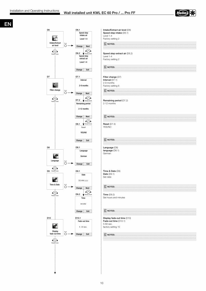
10
Wall installed unit KWL EC 60 Pro / . . . Pro FFInstallation and Operating Instructions
Intake/Extract air level (D6)Speed step intake (D6.1)Level 1-4Factory setting 2
Speed step extract air (D6.2)Level 1-4Factory setting 2
Filter change (D7)Interval (D7.1)2-9 monthsFactory setting 6
Remaining period (D7.2)2-12 months
Reset (D7.3)YES/NO
Language (D8) language (D8.1)German
Time & Date (D9)Date (D9.1)Set date
Time (D9.2)Set hours and minutes
Display fade-out time (D10)Fade-out time (D10.1)5-60 sec.factory setting 10
D6 D6 .1
D6 .2
D7 D7 .1
D7 .2
D6 .1
D8 .1
D9 .1
D9 .2
D8
D9
D10 .1D10
�NOTES: . . . . . . . . . . . . . . . . . . . . . . . . . . . . . . . . . . . . . . . . . . . . . . . . . . . . . . . . . . . . . . . . . . . . . . . . . . . . . . . . . . . . . . . . . . . . . . . . . . . . . . . . . . . . . . . . . . . . . . . . . . . . . . . . . . . . . . . . . . .
�NOTES: . . . . . . . . . . . . . . . . . . . . . . . . . . . . . . . . . . . . . . . . . . . . . . . . . . . . . . . . . . . . . . . . . . . . . . . . . . . . . . . . . . . . . . . . . . . . . . . . . . . . . . . . . . . . . . . . . . . . . . . . . . . . . . . . . . . . . . . . . . .
�NOTES: . . . . . . . . . . . . . . . . . . . . . . . . . . . . . . . . . . . . . . . . . . . . . . . . . . . . . . . . . . . . . . . . . . . . . . . . . . . . . . . . . . . . . . . . . . . . . . . . . . . . . . . . . . . . . . . . . . . . . . . . . . . . . . . . . . . . . . . . . . .
�NOTES: . . . . . . . . . . . . . . . . . . . . . . . . . . . . . . . . . . . . . . . . . . . . . . . . . . . . . . . . . . . . . . . . . . . . . . . . . . . . . . . . . . . . . . . . . . . . . . . . . . . . . . . . . . . . . . . . . . . . . . . . . . . . . . . . . . . . . . . . . . .
�NOTES: . . . . . . . . . . . . . . . . . . . . . . . . . . . . . . . . . . . . . . . . . . . . . . . . . . . . . . . . . . . . . . . . . . . . . . . . . . . . . . . . . . . . . . . . . . . . . . . . . . . . . . . . . . . . . . . . . . . . . . . . . . . . . . . . . . . . . . . . . . .
�NOTES: . . . . . . . . . . . . . . . . . . . . . . . . . . . . . . . . . . . . . . . . . . . . . . . . . . . . . . . . . . . . . . . . . . . . . . . . . . . . . . . . . . . . . . . . . . . . . . . . . . . . . . . . . . . . . . . . . . . . . . . . . . . . . . . . . . . . . . . . . . .
�NOTES: . . . . . . . . . . . . . . . . . . . . . . . . . . . . . . . . . . . . . . . . . . . . . . . . . . . . . . . . . . . . . . . . . . . . . . . . . . . . . . . . . . . . . . . . . . . . . . . . . . . . . . . . . . . . . . . . . . . . . . . . . . . . . . . . . . . . . . . . . . .
�NOTES: . . . . . . . . . . . . . . . . . . . . . . . . . . . . . . . . . . . . . . . . . . . . . . . . . . . . . . . . . . . . . . . . . . . . . . . . . . . . . . . . . . . . . . . . . . . . . . . . . . . . . . . . . . . . . . . . . . . . . . . . . . . . . . . . . . . . . . . . . . .
Speed step intake air
Filter change
Interval
2-9 months
Change Next
Change Next
Change Exit
Speed stepextract air
Level 1-4
Intake/Extract air level
Level 1-4
Change Next
Remaining period
2-12 months
Change Exit
YES/NO
Language
Language
German
Change Exit
Time & Date
Date
Change Next
Change Exit
Change Exit
Time
Fade-out time
Display fade-out time
EN
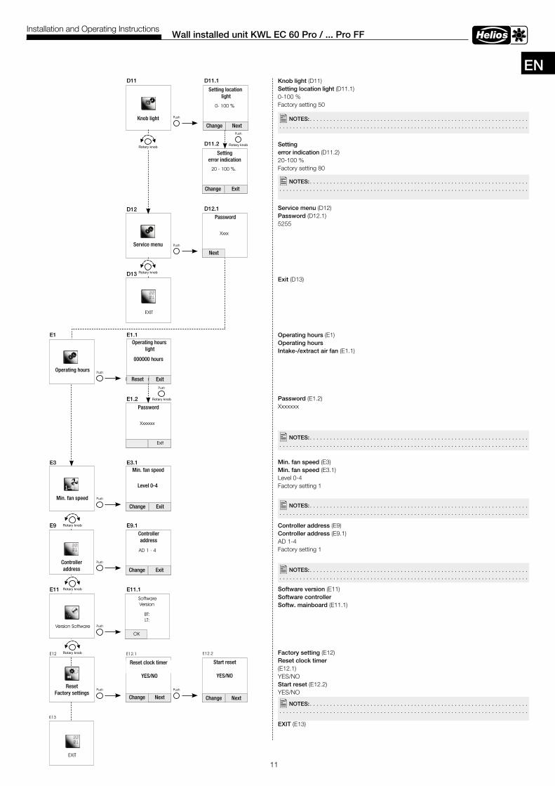
11
Wall installed unit KWL EC 60 Pro / . . . Pro FFInstallation and Operating Instructions
Knob light (D11)Setting location light (D11.1)0-100 %Factory setting 50
Setting error indication (D11.2)20-100 %Factory setting 80
Service menu (D12) Password (D12.1) 5255
Exit (D13)
Operating hours (E1)Operating hours Intake-/extract air fan (E1.1)
Password (E1.2) Xxxxxxx
Min . fan speed (E3)Min . fan speed (E3.1)Level 0-4Factory setting 1
Controller address (E9)Controller address (E9.1)AD 1-4Factory setting 1
Software version (E11)Software controller Softw . mainboard (E11.1)
Factory setting (E12)Reset clock timer(E12.1)YES/NOStart reset (E12.2)YES/NO
EXIT (E13)
D11 D11 .1
E1
D11 .2
D13
D12 .1D12
E1 .1
E1 .2
E3 E3 .1
E9 E9 .1
E11 E11 .1
�NOTES: . . . . . . . . . . . . . . . . . . . . . . . . . . . . . . . . . . . . . . . . . . . . . . . . . . . . . . . . . . . . . . . . . . . . . . . . . . . . . . . . . . . . . . . . . . . . . . . . . . . . . . . . . . . . . . . . . . . . . . . . . . . . . . . . . . . . . . . . . . .
�NOTES: . . . . . . . . . . . . . . . . . . . . . . . . . . . . . . . . . . . . . . . . . . . . . . . . . . . . . . . . . . . . . . . . . . . . . . . . . . . . . . . . . . . . . . . . . . . . . . . . . . . . . . . . . . . . . . . . . . . . . . . . . . . . . . . . . . . . . . . . . . .
�NOTES: . . . . . . . . . . . . . . . . . . . . . . . . . . . . . . . . . . . . . . . . . . . . . . . . . . . . . . . . . . . . . . . . . . . . . . . . . . . . . . . . . . . . . . . . . . . . . . . . . . . . . . . . . . . . . . . . . . . . . . . . . . . . . . . . . . . . . . . . . . .
�NOTES: . . . . . . . . . . . . . . . . . . . . . . . . . . . . . . . . . . . . . . . . . . . . . . . . . . . . . . . . . . . . . . . . . . . . . . . . . . . . . . . . . . . . . . . . . . . . . . . . . . . . . . . . . . . . . . . . . . . . . . . . . . . . . . . . . . . . . . . . . . .
�NOTES: . . . . . . . . . . . . . . . . . . . . . . . . . . . . . . . . . . . . . . . . . . . . . . . . . . . . . . . . . . . . . . . . . . . . . . . . . . . . . . . . . . . . . . . . . . . . . . . . . . . . . . . . . . . . . . . . . . . . . . . . . . . . . . . . . . . . . . . . . . .
�NOTES: . . . . . . . . . . . . . . . . . . . . . . . . . . . . . . . . . . . . . . . . . . . . . . . . . . . . . . . . . . . . . . . . . . . . . . . . . . . . . . . . . . . . . . . . . . . . . . . . . . . . . . . . . . . . . . . . . . . . . . . . . . . . . . . . . . . . . . . . . . .
Knob light
Setting location light
Change Next
Change Exit
Password
Next
Service menu
Setting error indication
Operating hours light
Password
Reset Exit
000000 hours
Operating hours
Min. fan speed
Min. fan speed
Level 0-4
Change Exit
Change Exit
Change Next Change Next
Controlleraddress
Controlleraddress
Reset clock timer
YES/NOYES/NO
Start reset
ResetFactory settings
EN
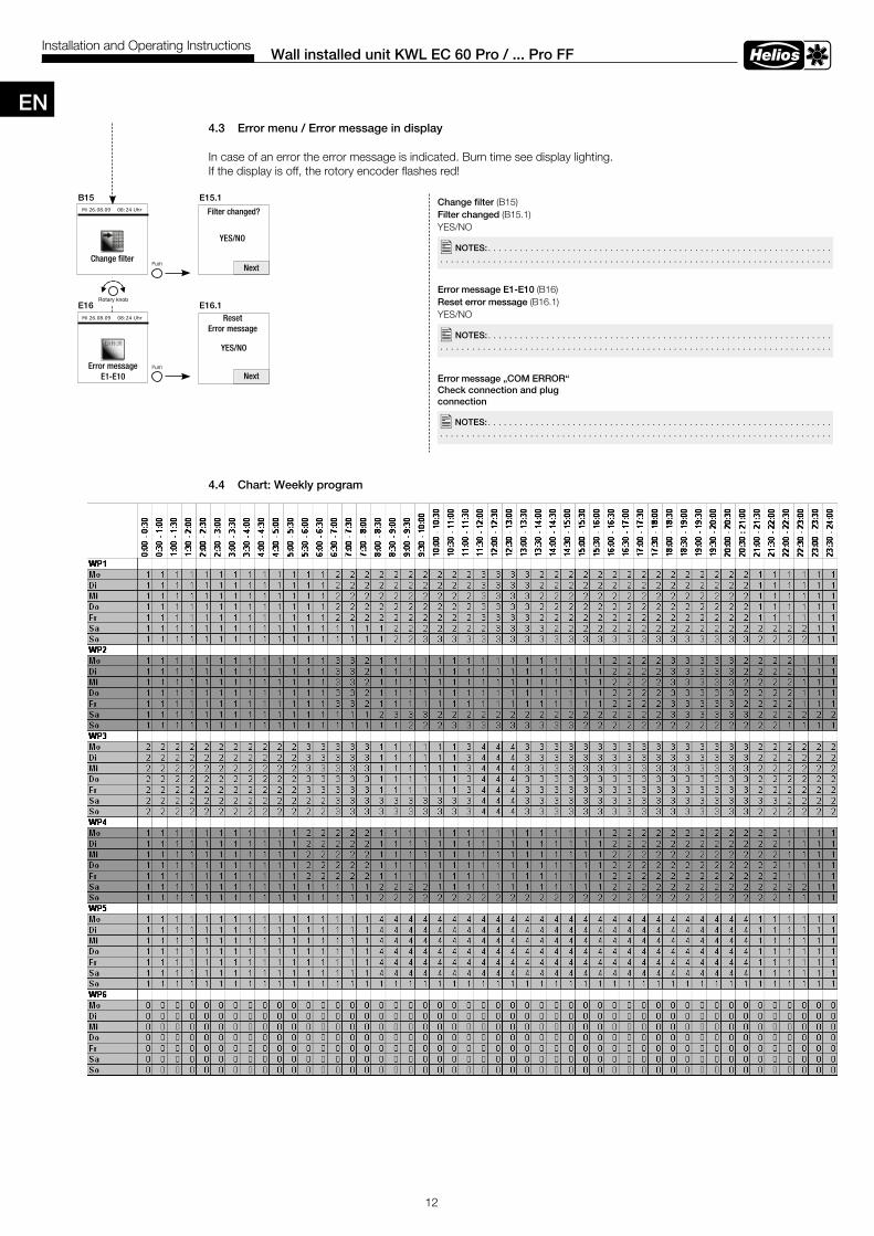
4 .3 Error menu / Error message in display
In case of an error the error message is indicated. Burn time see display lighting.If the display is off, the rotory encoder flashes red!
4 .4 Chart: Weekly program
12
Wall installed unit KWL EC 60 Pro / . . . Pro FFInstallation and Operating Instructions
Change filter (B15)Filter changed (B15.1)YES/NO
Error message E1-E10 (B16)Reset error message (B16.1)YES/NO
Error message „COM ERROR“Check connection and plug connection
�NOTES: . . . . . . . . . . . . . . . . . . . . . . . . . . . . . . . . . . . . . . . . . . . . . . . . . . . . . . . . . . . . . . . . . . . . . . . . . . . . . . . . . . . . . . . . . . . . . . . . . . . . . . . . . . . . . . . . . . . . . . . . . . . . . . . . . . . . . . . . . . .
�NOTES: . . . . . . . . . . . . . . . . . . . . . . . . . . . . . . . . . . . . . . . . . . . . . . . . . . . . . . . . . . . . . . . . . . . . . . . . . . . . . . . . . . . . . . . . . . . . . . . . . . . . . . . . . . . . . . . . . . . . . . . . . . . . . . . . . . . . . . . . . . .
�NOTES: . . . . . . . . . . . . . . . . . . . . . . . . . . . . . . . . . . . . . . . . . . . . . . . . . . . . . . . . . . . . . . . . . . . . . . . . . . . . . . . . . . . . . . . . . . . . . . . . . . . . . . . . . . . . . . . . . . . . . . . . . . . . . . . . . . . . . . . . . . .
B15 E15 .1
E16 E16 .1
Change filter
YES/NO
Filter changed?
Next
Next
YES/NO
Error messageE1-E10
ResetError message
EN
12
Wand-Einbaugerät KWL EC 60 Pro / ... Pro FFMontage- und Betriebsvorschrift
Luftfilter wechseln (B15)Luftfilter gewechselt (B15.1)JA/NEIN
Fehlermeldung E1-E10 (B16)Fehlermeldung rücksetzen(B16.1)JA/NEIN
4.3 Fehlermenü/Fehleranzeige im Display
Bei einem Fehler wird die Fehlermeldung angezeigt, Leuchtdauer siehe Displaybeleuchtung.Ist das Display aus, blinkt der Drehencoder rot!
4.4 Tabelle: Wochenprogramm
B15 E15.1
E16 E16.1
�NOTIZEN: . . . . . . . . . . . . . . . . . . . . . . . . . . . . . . . . . . . . . . . . . . . . . . . . . . . . . . . . . . . . . . .
�NOTIZEN: . . . . . . . . . . . . . . . . . . . . . . . . . . . . . . . . . . . . . . . . . . . . . . . . . . . . . . . . . . . . . . .
D
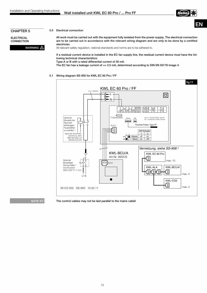
13
Wall installed unit KWL EC 60 Pro / . . . Pro FFInstallation and Operating Instructions
5 .0 Electrical connection
All work must be carried out with the equipment fully isolated from the power supply . The electrical connection are to be carried out in accordance with the relevant wiring diagram and are only to be done by a certified electrician .All relevant safety regulation, national standards and norms are to be adhered to.
If a residual current device is installed in the EC fan supply line, the residual current device must have the fol-lowing technical characteristics:Type A or B with a rated differential current of 30 mA .The EC fan has a leakage current of <= 3 .5 mA, determined according to DIN EN 50178 image 4 .
5 .1 Wiring diagram SS-950 for KWL EC 60 Pro / FF
The control cables may not be laid parallel to the mains cable!
CHAPTER 5
ELECTRICAL CONNECTION
WARNING m
fig .11
KWL EC 60 Pro / FF
L1 N
Optional:Bauseitiger
On/off switchTrennschalter /
VDE 0700 T1 7.12.2
Signal der Sicherheits-einrichtung, siehe
MBV-Montage undBetriebsvorschrift
Optional:Bauseits beiRaumluft-abhängigenFeuerstättenzu erstellen !
L
N
2 x 1,5mm²
85123 002 SS-950 10.02.11
KWL-BCU/AArt.Nr. 9955/6
L N LA N LZ N TR-PR
ITR
-PRI
TR-SE
CTR
-SEC
+ AB - + ZU -
HumiT100mA/250V
RJ12
RJ12
6
KWL EC 60 Pro
KWL-ALA KWL-BCU/A
KWL-CO2
max. 4
max. 4
off
on1 2
Vernetzung, siehe SS-958 !
FS Humi = Feuchte-Fühler, Type FFFS = Frostschutz-Fühler, Sonder
Feuchte-Fühler, Type FF
max. 10
DIP-Schalter1 2
Master off onSlave on off
NOTE +
EN
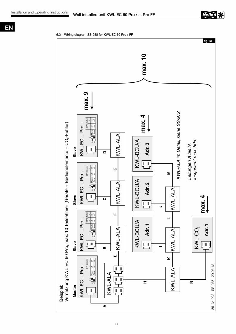
14
Wall installed unit KWL EC 60 Pro / . . . Pro FFInstallation and Operating Instructions
5 .2 Wiring diagram SS-958 for KWL EC 60 Pro / FF
8513
4 00
2 S
S-9
58
29.0
5.12
KW
L-B
CU
/A
Ad
r.1
KW
L E
C ..
.Pro
..
KW
L-A
LA
KW
L-C
O2
max
.4
max
.4A
dr.
1
Bei
spie
l:V
erne
tzun
g K
WL
EC
60
Pro
, max
.10
Teiln
ehm
er (
Ger
äte
+ B
edie
nele
men
te +
CO
-F
ühle
r)2
KW
L-B
CU
/A
Ad
r.2
KW
L-B
CU
/A
Ad
r.3
KW
L-A
LAK
WL-
ALA
KW
L-A
LA
KW
L-A
LAK
WL-
ALA
KW
L-A
LA
AB
CD
EF
G
H
IJ
KL
M
NLe
itung
en A
bis
N,
insg
esam
t max
.50m
KW
L E
C ..
.Pro
..K
WL
EC
...P
ro ..
KW
L E
C ..
.Pro
..
Mas
ter
Sla
veS
lave
Sla
ve
max
.10
KW
L-A
LA im
Det
ail,
sieh
e S
S-9
72
off
on1
2
DIP
-Sch
alte
r1
2M
aste
rof
fon
Sla
veon
off
off
on1
2
DIP
-Sch
alte
r1
2M
aste
rof
fon
Sla
veon
off
off
on1
2
DIP
-Sch
alte
r1
2M
aste
rof
fon
Sla
veon
off
off
on1
2
DIP
-Sch
alte
r1
2M
aste
rof
fon
Sla
veon
off
max
.9
fig .13
EN
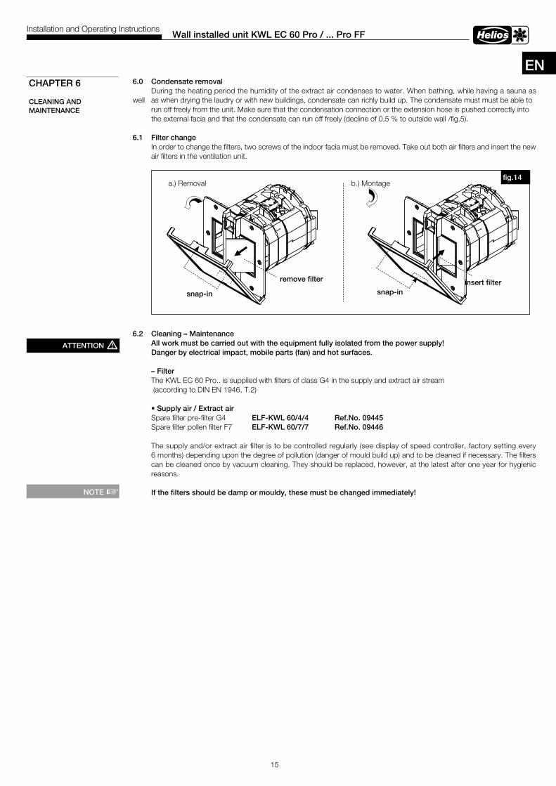
15
Wall installed unit KWL EC 60 Pro / . . . Pro FFInstallation and Operating Instructions
6 .0 Condensate removal During the heating period the humidity of the extract air condenses to water. When bathing, while having a sauna as well as when drying the laudry or with new buildings, condensate can richly build up. The condensate must must be able to run off freely from the unit. Make sure that the condensation connection or the extension hose is pushed correctly into the external facia and that the condensate can run off freely (decline of 0,5 % to outside wall /fig.5).
6 .1 Filter change In order to change the filters, two screws of the indoor facia must be removed. Take out both air filters and insert the new air filters in the ventilation unit.
6 .2 Cleaning – Maintenance All work must be carried out with the equipment fully isolated from the power supply! Danger by electrical impact, mobile parts (fan) and hot surfaces .
– Filter The KWL EC 60 Pro.. is supplied with filters of class G4 in the supply and extract air stream (according to DIN EN 1946, T.2) • Supply air / Extract air Spare filter pre-filter G4 ELF-KWL 60/4/4 Ref .No . 09445 Spare filter pollen filter F7 ELF-KWL 60/7/7 Ref .No . 09446 The supply and/or extract air filter is to be controlled regularly (see display of speed controller, factory setting every 6 months) depending upon the degree of pollution (danger of mould build up) and to be cleaned if necessary. The filters can be cleaned once by vacuum cleaning. They should be replaced, however, at the latest after one year for hygienic reasons.
If the filters should be damp or mouldy, these must be changed immediately!
CHAPTER 6
CLEANING ANDMAINTENANCE
ATTENTION m
a.) Removal b.) Montage
remove filter
snap-in
insert filtersnap-in
fig .14
NOTE +
EN
FRANÇAISHelios VentilatorenNOTICE DE MONTAGE ET D’UTILISATION
Sommaire
CHAPITRE 1 . INFORMATIONS GENERALES . . . . . . . . . . . . . . . . . . . . . . . . . . . . . . . . . . . . . . . . . . . . . . . . . . . . . Page 11.0 Informations importantes . . . . . . . . . . . . . . . . . . . . . . . . . . . . . . . . . . . . . . . . . . . . . . . . . . . . . . . . . . . . . . . . Page 11.1 Précautions et consignes de sécurité . . . . . . . . . . . . . . . . . . . . . . . . . . . . . . . . . . . . . . . . . . . . . . . . . . . . . . Page 11.2 Demande de garantie - Réserves du constructeur . . . . . . . . . . . . . . . . . . . . . . . . . . . . . . . . . . . . . . . . . . . . . Page 11.3 Réglementation - Normes . . . . . . . . . . . . . . . . . . . . . . . . . . . . . . . . . . . . . . . . . . . . . . . . . . . . . . . . . . . . . . . Page 11.4 Réception de l’envoi . . . . . . . . . . . . . . . . . . . . . . . . . . . . . . . . . . . . . . . . . . . . . . . . . . . . . . . . . . . . . . . . . . . Page 11.5 Stockage . . . . . . . . . . . . . . . . . . . . . . . . . . . . . . . . . . . . . . . . . . . . . . . . . . . . . . . . . . . . . . . . . . . . . . . . . . . Page 11.6 Domaine d’utilisation . . . . . . . . . . . . . . . . . . . . . . . . . . . . . . . . . . . . . . . . . . . . . . . . . . . . . . . . . . . . . . . . . . . Page 11.7 Fonctionnement . . . . . . . . . . . . . . . . . . . . . . . . . . . . . . . . . . . . . . . . . . . . . . . . . . . . . . . . . . . . . . . . . . . . . . Page 11.8 Performances . . . . . . . . . . . . . . . . . . . . . . . . . . . . . . . . . . . . . . . . . . . . . . . . . . . . . . . . . . . . . . . . . . . . . . . . Page 11.9 Foyers ouverts . . . . . . . . . . . . . . . . . . . . . . . . . . . . . . . . . . . . . . . . . . . . . . . . . . . . . . . . . . . . . . . . . . . . . . . Page 11.10 Raccordement électrique . . . . . . . . . . . . . . . . . . . . . . . . . . . . . . . . . . . . . . . . . . . . . . . . . . . . . . . . . . . . . . . Page 21.11 Caractéristiques techniques . . . . . . . . . . . . . . . . . . . . . . . . . . . . . . . . . . . . . . . . . . . . . . . . . . . . . . . . . . . . . Page 21.12 Accessoires . . . . . . . . . . . . . . . . . . . . . . . . . . . . . . . . . . . . . . . . . . . . . . . . . . . . . . . . . . . . . . . . . . . . . . . . . Page 2
CHAPITRE 2 . FOURNITURE / COMMANDE . . . . . . . . . . . . . . . . . . . . . . . . . . . . . . . . . . . . . . . . . . . . . . . . . . . . . . Page 22.0 Fourniture / Commande . . . . . . . . . . . . . . . . . . . . . . . . . . . . . . . . . . . . . . . . . . . . . . . . . . . . . . . . . . . . . . . . Page 2
CHAPITRE 3 . MONTAGE / DISPOSITION . . . . . . . . . . . . . . . . . . . . . . . . . . . . . . . . . . . . . . . . . . . . . . . . . . . . . . . . Page 33.0 Montage mural du kit gros oeuvre KWL 60 RS . . . . . . . . . . . . . . . . . . . . . . . . . . . . . . . . . . . . . . . . . . . . . . . Page 33.1 Pose des câbles d’alimentation et de commande . . . . . . . . . . . . . . . . . . . . . . . . . . . . . . . . . . . . . . . . . . . . . Page 33.2 Montage de l’unité de ventilation KWL EC 60 Pro /...Pro FF . . . . . . . . . . . . . . . . . . . . . . . . . . . . . . . . . . . . . Page 33.3 Montage rallonge manchon mural KWL 60 WV . . . . . . . . . . . . . . . . . . . . . . . . . . . . . . . . . . . . . . . . . . . . . . Page 33.4 Montage de l’entretoise KWL 60 DR . . . . . . . . . . . . . . . . . . . . . . . . . . . . . . . . . . . . . . . . . . . . . . . . . . . . . . Page 4
CHAPITRE 4 . COMMANDE A DISTANCE KWL-BCU / KWL-BCA . . . . . . . . . . . . . . . . . . . . . . . . . . . . . . . . . . . . Page 44.0 Descriptif des différentes fonctions . . . . . . . . . . . . . . . . . . . . . . . . . . . . . . . . . . . . . . . . . . . . . . . . . . . . . . . . Page 44.1 Commande à distance KWL 60 BC... . . . . . . . . . . . . . . . . . . . . . . . . . . . . . . . . . . . . . . . . . . . . . . . . . . . . . . Page 64.2 Arborescence du menu . . . . . . . . . . . . . . . . . . . . . . . . . . . . . . . . . . . . . . . . . . . . . . . . . . . . . . . . . . . . . . . . Page 64.3 Liste des messages d’erreur . . . . . . . . . . . . . . . . . . . . . . . . . . . . . . . . . . . . . . . . . . . . . . . . . . . . . . . . . . . . Page 124.4 Tableau: programmation hebdomadaire . . . . . . . . . . . . . . . . . . . . . . . . . . . . . . . . . . . . . . . . . . . . . . . . . . . Page 12
CHAPITRE 5 . RACCORDEMENT ELECTRIQUE . . . . . . . . . . . . . . . . . . . . . . . . . . . . . . . . . . . . . . . . . . . . . . . . . Page 135.0 Raccordement électrique . . . . . . . . . . . . . . . . . . . . . . . . . . . . . . . . . . . . . . . . . . . . . . . . . . . . . . . . . . . . . . Page 135.1 Schéma de branchement SS-950 . . . . . . . . . . . . . . . . . . . . . . . . . . . . . . . . . . . . . . . . . . . . . . . . . . . . . . . . Page 135.2 Schéma de branchement SS-958 . . . . . . . . . . . . . . . . . . . . . . . . . . . . . . . . . . . . . . . . . . . . . . . . . . . . . . . . Page 14
CHAPITRE 6 . NETTOYAGE ET ENTRETIEN . . . . . . . . . . . . . . . . . . . . . . . . . . . . . . . . . . . . . . . . . . . . . . . . . . . . . Page 156.0 Evacuation des condensats . . . . . . . . . . . . . . . . . . . . . . . . . . . . . . . . . . . . . . . . . . . . . . . . . . . . . . . . . . . . Page 156.1 Remplacement des filtres . . . . . . . . . . . . . . . . . . . . . . . . . . . . . . . . . . . . . . . . . . . . . . . . . . . . . . . . . . . . . . Page 156.2 Nettoyage – Entretien . . . . . . . . . . . . . . . . . . . . . . . . . . . . . . . . . . . . . . . . . . . . . . . . . . . . . . . . . . . . . . . . . Page 15
Tri correct de ce produit (Appareillage électronique)Le sigle présent sur ce produit et sur la notice de montage et d’utilisation indique, qu’en fin de vie, celui–ci ne doit pas être jeté avec les ordures ménagères classiques. Ne mettez pas cet appareil avec les autres déchets pour ne pas nuire à l’environnement, ni à la santé publique suite à un recyclage d’ordures non contrôlées. Recycler cet appareil pour encourager la récupération efficace des ressources.Le particulier devrait contacter le revendeur, chez lequel ce produit a été acheté, ou les autorités compétentes, pour s’informer de la meilleure façon de recycler l’appareil.Les utilisateurs professionnels devraient s’adresser à leurs fournisseurs et consulter les modalités du contrat de vente. Ce produit ne doit pas être trié avec les autres déchets industriels.
ASTUCE!
1
FR1 .0 Informations importantes
Il est important de bien lire et respecter l’ensemble des prescriptions suivantes pour le bon fonctionnement de l’appareil et la sécurité des utilisateurs. L’alimentation électrique doit être maintenue hors tension jusqu’à la fin de l’instal-lation ! Conserver la notice de montage et d’utilisation comme référence à proximité de l’appareil. Une fois le montage terminé, ce document doit être remis en mains propres à l’utilisateur (locataire/propriétaire).
1 .1 Précautions et consignes de sécurité Le symbole ci-contre indique une consigne de sécurité . Toutes les consignes de sécurité, ainsi que les symboles, doivent impérativement être respectés, afin d’éviter tout danger .
1 .2 Demande de garantie – Réserves du constructeur En cas de non-respect des indications suivantes, toute demande de remplacement ou de réparation à titre gratuit sera déclinée. Il en sera de même pour toute implication de responsabilité du fabricant. L’utilisation d’accessoires et d’équipements qui ne sont directement fournis ou conseillés par Helios n’est pas permi-se. Nous déclinons toute responsabilité en cas de défaut consécutif à leur utilisation.
1 .3 Réglementation – NormesCet appareil est conforme aux directives CE en vigueur le jour de sa fabrication sous réserve d’une utilisation appropriée.
1 .4 Réception de l’envoiDès réception, vérifier l’état et la conformité du matériel commandé. En cas d’avaries, des réserves doivent être portées sur le bordereau du transporteur. Elles doivent être précises, significatives, complètes et confirmées par lettre recom-mandée au transporteur. Attention le non-respect de la procédure peut entraîner le rejet de la réclamation.
1 .5 Stockage Pour un stockage de plus longue durée, se conformer aux instructions suivantes, pour éviter toutes détériorations préjudiciables :Protection grâce à un emballage sec, étanche à l’air et la poussière (sac en matière synthétique contenant des sachets deshydrateurs et un indicateur d’humidité). Le matériel est à stocker dans un endroit abrité de l’eau, exempt de varia-tion de températures et de vibrations. Les dommages dus à de mauvaises conditions de transport ou de stockage, à une utilisation anormale sont sujets à vérification et contrôle et entraînent la suppression de notre garantie.
1 .6 Domaine d’utilisation Le groupe double flux mural à récupération de chaleur KWL EC 60 Pro /... Pro FF est conçu pour l’insufflation et l’ex-traction d’air dans les petits et grands locaux individuels. Pour les locaux nécessitant des débits d’air plus importants, nous conseillons l’utilisation de deux appareils. L’appareil de série permet un montage et une utilisation dans des locaux à l’abri du gel (jusqu’à + 5°C). En cas d’utilisation sous conditions sévères, par exemple forte hygrométrie, temps de pause importants, ambiance poussiéreuse, ambiance tropicale, incidences techniques et électromagnétiques particu-lières, il convient de demander conseil et d’obtenir une autorisation du constructeur.Toute autre utilisation n’est pas autorisée !
1 .7 FonctionnementL’air neuf froid et l’air extrait chaud se croisent dans l’échangeur à plaques sans contact direct entre eux. Grâce à ce procédé, plus de 70 % de la chaleur contenue dans l’air extrait est transmise à l’air soufflé.
1 .8 Performances Un montage selon les règles de l’art ainsi qu’une aspiration et un soufflage sans entrave sont la garantie d’un bon fonctionnement.
1 .9 Foyers ouverts Les prescriptions en vigueur pour le fonctionnement commun des foyers, de la ventilation de l‘habitation et de la hotte aspirante doivent être observées !
Exigences de construction généralesLes appareils de ventilation avec récupération de chaleur KWL ne peuvent être installés et exploités dans des pièces avec d‘autres foyers asservis à l‘air ambiant que si l‘évacuation des gaz de fumée est surveillée par des dispositifs de sécurité spécifiques qui arrêtent également l‘installation de ventilation KWL en cas de défaillance.
Demandez conseil à votre ramoneur avant l’achat d’un système de surveillance.
CHAPITRE 1
INFORMATIONS GENERALES
m
CONSIGNE +
Groupe double flux mural KWL EC 60 Pro / . . . Pro FFNotice de montage et d’utilisation
IMPORTANT +
IMPORTANT +
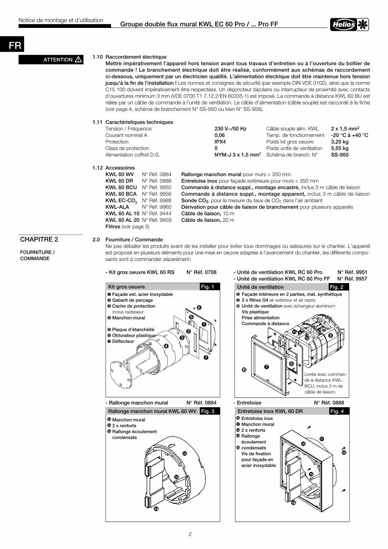
2
FR
Groupe double flux mural KWL EC 60 Pro / . . . Pro FFNotice de montage et d’utilisation
Ì
Ì
Ì
Ì
11
12
12
13
11
13
1 .10 Raccordement électrique Mettre impérativement l’appareil hors tension avant tous travaux d’entretien ou à l’ouverture du boîtier de commande ! Le branchement électrique doit être réalisé, conformément aux schémas de raccordement ci-dessous, uniquement par un électricien qualifié . L’alimentation électrique doit être maintenue hors tension jusqu’à la fin de l’installation ! Les normes et consignes de sécurité (par exemple DIN VDE 0100), ainsi que la norme C15 100 doivent impérativement être respectées. Un disjoncteur bipolaire ou interrupteur de proximité avec contacts d’ouvertures minimum 3 mm (VDE 0700 T1 7.12.2/EN 60335-1) est imposé. La commande à distance KWL 60 BU est reliée par un câble de commande à l’unité de ventilation. Le câble d’alimentation (câble souple) est raccordé à la fiche (voir page 4, schéma de branchement N° SS-950 ou bien N° SS-958).
1 .11 Caractéristiques techniques Tension / Fréquence 230 V~/50 Hz Câble souple alim. KWL 2 x 1,5 mm2
Courant nominal A 0,06 Temp. de fonctionnement -20 °C à +40 °CProtection IPX4 Poids kit gros oeuvre 3,25 kgClass de protection II Poids unité de ventilation 5,55 kg Alimentation coffret D.S. NYM-J 3 x 1,5 mm2 Schéma de branch. N° SS-950
1 .12 Accessoires KWL 60 WV N° Réf. 0884 Rallonge manchon mural pour murs > 350 mm KWL 60 DR N° Réf. 0888 Entretoise inox pour façade extérieure pour murs < 350 mm KWL 60 BCU N° Réf. 9955 Commande à distance suppl ., montage encastré, inclus 3 m câble de liaison KWL 60 BCA N° Réf. 9956 Commande à distance suppl ., montage apparent, inclus 3 m câble de liaison KWL EC-CO2 N° Réf. 9988 Sonde CO2, pour la mesure du taux de CO2 dans l’air ambiant KWL-ALA N° Réf. 9960 Dérivation pour câble de liaison de branchement pour plusieurs appareils KWL 60 AL 10 N° Réf. 9444 Câble de liaison, 10 m KWL 60 AL 20 N° Réf. 9959 Câble de liaison, 20 m Filtres (voir page 5) 2 .0 Fourniture / Commande
Ne pas déballer les produits avant de les installer pour éviter tous dommages ou salissures sur le chantier. L’appareil est proposé en plusieurs éléments pour une mise en oeuvre adaptée à l’avancement du chantier, les différents compo-sants sont à commander séparément:
- Kit gros oeuvre KWL 60 RS N° Réf . 0708 - Unité de ventilation KWL RC 60 Pro N° Réf . 9951 - Unité de ventilation KWL RC 60 Pro FF N° Réf . 9957
- Rallonge manchon mural N° Réf . 0884 - Entretoise N° Réf . 0888
21
19
20
18
17
17
18
19
20
21
14
15
16
15
16
14
Rallonge manchon mural KWL 60 WV Fig . 3 Entretoise inox KWL 60 DR Fig . 4
Manchon mural 2 x renfortsRallonge écoulement condensats
Entretoise inoxManchon mural2 x renfortsRallonge écoulementcondensatsVis de fixation pour façade enacier inoxydable
20
18
19
17
16
16
17
18
19
20
13
14
15
14
15
13
Kit gros oeuvre
ä
ò
Fig . 1
ù
CHAPITRE 2
FOURNITURE /COMMANDE
ATTENTION m
Unité de ventilation
ö
Fig . 2
Å î
Ø
ü
ò Façade ext . acier inoxydableù Gabarit de perçageä Cache de protection inclus raidisseurë Manchon mural ö Plaque d’étanchéitéü Obturateur plastiqueÅ Déflecteur
î Façade intérieure en 2 parties, mat . synthétiqueØ2 x filtres G4 air extérieur et air reprisÆUnité de ventilation avec échangeur aluminium Vis plastique Prise alimentation Commande à distance
Å
Livrée avec comman-de à distance KWL-BCU, inclus 3 m de câble de liaison.
ë
Æ
11
12
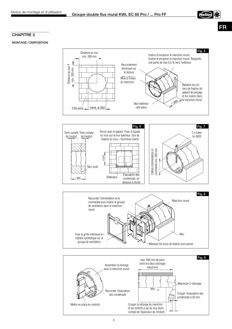
3
FR
Groupe double flux mural KWL EC 60 Pro / . . . Pro FFNotice de montage et d’utilisation
CHAPITRE 3
MONTAGE / DISPOSITION
Trennsteg auf das Gehäuseder Lüftungseinheit aufstecken
Wandring aufWandhülseaufstecken
VerlängerungKondensatablaufaufstecken
Fig . 9
max. 560 mmWanddicke bei zwei
Verlängerungshülsen
(Putzstärke beachten)
Wandring und Trennstegwandbündig abschneiden
mit 20 mm Überstandzur Wand ablängen
Kondensatablauf
max. 455 mmWanddicke bei einerVerlängerungshülse
max. 2 Wandhülsen-Verlängerungen
Wand
Wand
WandhülseNetz.- und Steuerleitunganschließen und denLüftungseinsatz in dieWandhülse einschieben
Bohrbild abbohren
Kunststofffassade ander Innenwand bzw.am Lüftungseinsatzbefestigen.
Fig . 8
ca. 2
00 m
m
Ste
uer.-
und
Net
zzul
eitu
ng
2xLeerrohr M20
Fig .7
2 x tubes Iro M20
Câbl
es d
’alim
enta
tion
et
com
man
de e
nv. 2
00 m
m
Raccorder l’alimentation et la commande puis insérer le groupe de ventilation dans le manchon mural
Manchon mural
Mur Fixer la grille intérieure en matière synthétique sur le
groupe de ventilation
Assembler la rallonge avec le manchon mural
Raccorder l’évacuation des condensats
Mettre en place les renforts
Mur
Maximum 2 rallonges
Couper l’évacuation des condensats à 20 mm du mur
Couper la rallonge du manchon et les renforts à ras du mur (tenir compte de l’épaisseur de l’enduit)
mind. 350Wandabstand
min
d. 3
50D
ecke
nabs
tand
mind. ø 352Raumseitig~ 350
Wandhülse einschieben.Diese muss mit einem leichten Gefälle,von max. 0,5 % zur Außenwand hin,eingeputzt werden.
Außenwandraumseitig
Wandhülsehorizontal mitWasserwaageausrichten
Netzanschlußoben
Laschen derBohrschabloneabklappen undin Wandhülseeinschieben
Fig . 5Distance au mur
min. 350 mm
Côté pièce
Dist
ance
au
mur
m
in. 3
50 m
m
Raccordement électrique sur
le dessus
Mise à niveau du manchon
Mur extérieur côté pièce
Insérer et encastrer le manchon mural.Insérer et encastrer le manchon mural. Respecter une pente de max 0,5 % vers l‘extérieur.
Rabattre les col-liers de fixation du gabarit de perçage et les insérer dans le manchon mural
beachtenPutzstärke
beachtenPutzstärke
~ 350
Wand mitIsolierung
310
Bohrbild mittels Schablone abbohren.Edelstahlfassade und Abtropfblechan der Außenwand befestigen.(Befestigungsschrauben aus Edelstahlbauseits)
Kondensatablaufrechts unten
Abtropfblech
Fig . 6
Tenir compte de l’enduit
Tenir compte de l’enduit
Mur isolé
Evacuation des condensats, en
dessous à droite
Percer avec le gabarit. Fixer la façade en inox sur le mur extérieur. (Vis de fixation en inox = fourniture client)
Déflecteur
Marquer les trous de fixation puis percer.
max. 560 mm de paroi entre les deux rallonges
manchons
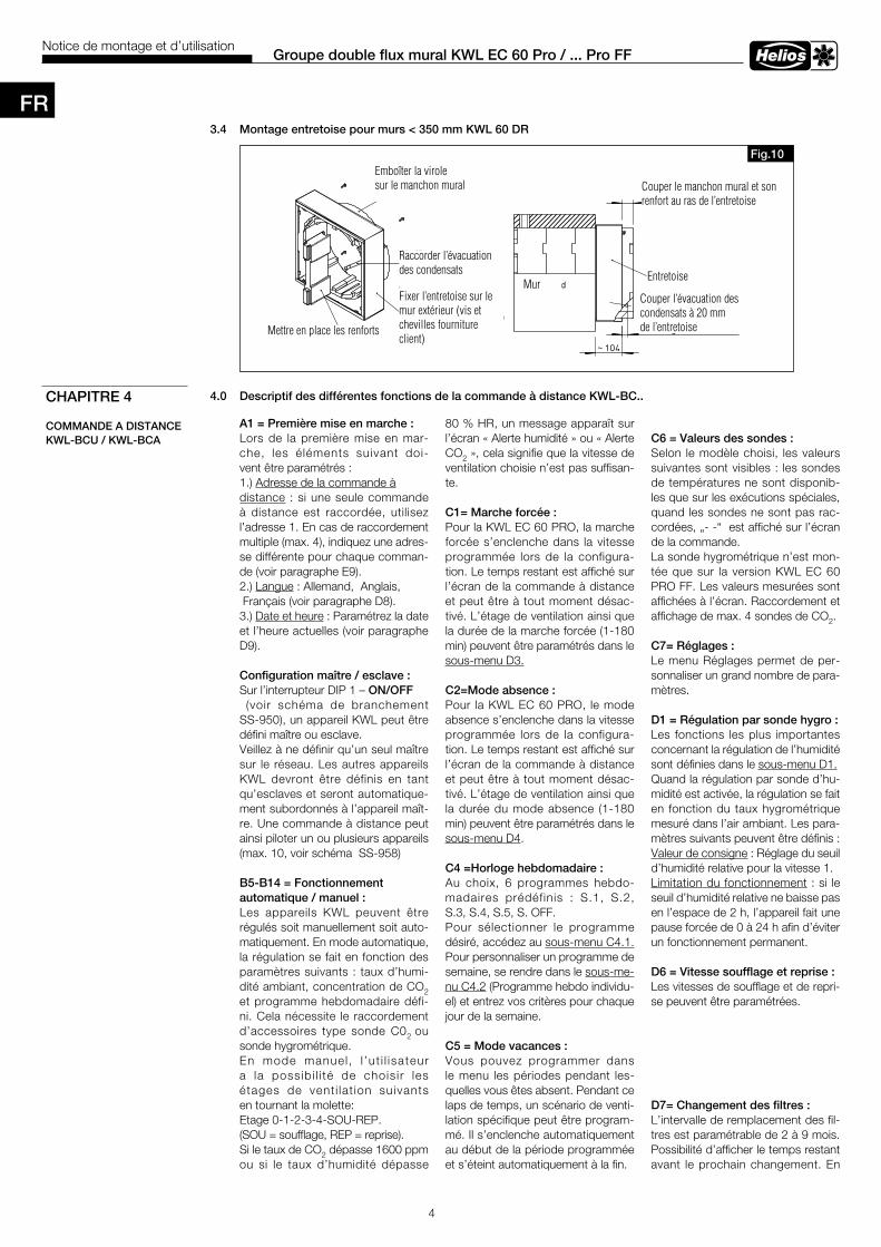
4
Groupe double flux mural KWL EC 60 Pro / . . . Pro FFNotice de montage et d’utilisation
3 .4 Montage entretoise pour murs < 350 mm KWL 60 DR
4 .0 Descriptif des différentes fonctions de la commande à distance KWL-BC . .CHAPITRE 4
COMMANDE A DISTANCE KWL-BCU / KWL-BCA
A1 = Première mise en marche :Lors de la première mise en mar-che, les éléments suivant doi-vent être paramétrés : 1.) Adresse de la commande àdistance : si une seule commande à distance est raccordée, utilisez l’adresse 1. En cas de raccordement multiple (max. 4), indiquez une adres-se différente pour chaque comman-de (voir paragraphe E9).2.) Langue : Allemand, Anglais, Français (voir paragraphe D8). 3.) Date et heure : Paramétrez la date et l’heure actuelles (voir paragraphe D9).
Configuration maître / esclave :Sur l’interrupteur DIP 1 – ON/OFF (voir schéma de branchement SS-950), un appareil KWL peut être défini maître ou esclave. Veillez à ne définir qu’un seul maître sur le réseau. Les autres appareils KWL devront être définis en tant qu’esclaves et seront automatique-ment subordonnés à l’appareil maît-re. Une commande à distance peut ainsi piloter un ou plusieurs appareils (max. 10, voir schéma SS-958)
B5-B14 = Fonctionnement automatique / manuel : Les appareils KWL peuvent être régulés soit manuellement soit auto-matiquement. En mode automatique, la régulation se fait en fonction des paramètres suivants : taux d’humi-dité ambiant, concentration de CO2 et programme hebdomadaire défi-ni. Cela nécessite le raccordement d’accessoires type sonde C02 ou sonde hygrométrique. En mode manuel , l ’ut i l isateur a la possibi l i té de chois i r les étages de vent i lat ion suivants en tournant la molette: Etage 0-1-2-3-4-SOU-REP. (SOU = soufflage, REP = reprise). Si le taux de CO2 dépasse 1600 ppm ou si le taux d’humidité dépasse
SS-932Trennsteg auf das Gehäuse
der Lüftungseinheit aufstecken
VerlängerungKondensatablaufaufstecken
Wandring aufWandhülseaufstecken
Distanzrahmen an derAußenwand befestigen(Befestigungsschraubenaus Edelstahl bauseits)
Fig .10
abschneiden
Wandring und Trennstegbündig mit Distanzrahmen
~ 104
mit 20 mm Überstandzum Distanzrahmenablängen
KondensatablaufWand
Distanzrahmen
Emboîter la virolesur le manchon mural
Raccorder l’évacuation des condensats
Mettre en place les renforts
Couper le manchon mural et son renfort au ras de l’entretoise
EntretoiseMur
Couper l’évacuation des condensats à 20 mm de l’entretoise
80 % HR, un message apparaît sur l’écran « Alerte humidité » ou « Alerte CO2 », cela signifie que la vitesse de ventilation choisie n’est pas suffisan-te.
C1= Marche forcée : Pour la KWL EC 60 PRO, la marche forcée s’enclenche dans la vitesse programmée lors de la configura-tion. Le temps restant est affiché sur l’écran de la commande à distance et peut être à tout moment désac-tivé. L’étage de ventilation ainsi que la durée de la marche forcée (1-180 min) peuvent être paramétrés dans le sous-menu D3.
C2=Mode absence :Pour la KWL EC 60 PRO, le mode absence s’enclenche dans la vitesse programmée lors de la configura-tion. Le temps restant est affiché sur l’écran de la commande à distance et peut être à tout moment désac-tivé. L’étage de ventilation ainsi que la durée du mode absence (1-180 min) peuvent être paramétrés dans le sous-menu D4.
C4 =Horloge hebdomadaire :Au choix, 6 programmes hebdo-madaires prédéfinis : S.1, S.2, S.3, S.4, S.5, S. OFF. Pour sélectionner le programme désiré, accédez au sous-menu C4.1. Pour personnaliser un programme de semaine, se rendre dans le sous-me-nu C4.2 (Programme hebdo individu-el) et entrez vos critères pour chaque jour de la semaine.
C5 = Mode vacances : Vous pouvez programmer dans le menu les périodes pendant les-quelles vous êtes absent. Pendant ce laps de temps, un scénario de venti-lation spécifique peut être program-mé. Il s’enclenche automatiquement au début de la période programmée et s’éteint automatiquement à la fin.
C6 = Valeurs des sondes :Selon le modèle choisi, les valeurs suivantes sont visibles : les sondes de températures ne sont disponib-les que sur les exécutions spéciales, quand les sondes ne sont pas rac-cordées, „- -“ est affiché sur l’écran de la commande. La sonde hygrométrique n’est mon-tée que sur la version KWL EC 60 PRO FF. Les valeurs mesurées sont affichées à l’écran. Raccordement et affichage de max. 4 sondes de CO2.
C7= Réglages :Le menu Réglages permet de per-sonnaliser un grand nombre de para-mètres.
D1 = Régulation par sonde hygro :Les fonctions les plus importantes concernant la régulation de l’humidité sont définies dans le sous-menu D1.Quand la régulation par sonde d’hu-midité est activée, la régulation se fait en fonction du taux hygrométrique mesuré dans l’air ambiant. Les para-mètres suivants peuvent être définis :Valeur de consigne : Réglage du seuil d’humidité relative pour la vitesse 1.Limitation du fonctionnement : si le seuil d’humidité relative ne baisse pas en l’espace de 2 h, l’appareil fait une pause forcée de 0 à 24 h afin d’éviter un fonctionnement permanent. D6 = Vitesse soufflage et reprise :Les vitesses de soufflage et de repri-se peuvent être paramétrées.
D7= Changement des filtres :L’intervalle de remplacement des fil-tres est paramétrable de 2 à 9 mois. Possibilité d’afficher le temps restant avant le prochain changement. En
Fixer l’entretoise sur le mur extérieur (vis et chevilles fourniture client)
FR
5
Groupe double flux mural KWL EC 60 Pro / . . . Pro FFNotice de montage et d’utilisation
cas de remplacement prématuré, veiller à réinitialiser le temps restant.
D8= Langue : Choix de langue (Allemand, Anglais, Français).
D9 = Heure et date :Réglage de la date et heure actuelles (fuseau horaire). D10= Temporisation éclairage écran (rétro-éclairage) :La temporisation de l’éclairage de l’écran est réglable de 5 à 30 secon-des. Sans action sur la commande à distance pendant le temps sélection-né, l’écran s’éteint et retourne dans le menu de base.
D11 = Eclairage de la molette : Veilleuse : Lorsque l’écran est éteint, la molette est éclairée en bleu. L’in-tensité de l’éclairage est réglable de 0 à 100 %.Témoin défaut : Lorsque l’écran est éteint et qu’un dysfonctionnement survient, la molette clignote en rouge. La luminosité est réglable de 20 à 100%. D12 = Menu expert :De nombreux paramètres peuvent être configurés dans le menu expert. Pour accéder à ce menu, entrez le mot de passe 5255.
E1 = Affichage compteur horaire :Le comptage des heures de foncti-onnement se déclenche dès qu’un des ventilateurs se met en route. Ce compteur ne peut être réinitialisé qu’en usine.
E2= Protection anti-gel échangeur:De 0 à 10°C.
E3= Vitesse min . :La vitesse minimale peut être réglée entre 0 et 1. Lorsque la vitesse 0 est définie, l’appareil KWL peut être éteint. Si la vitesse 1 est définie, la vitesse 0 ne peut être activée, même dans le programme hebdomadaire.
E9 = Adresse de la commande à distance :L’adresse de la commande à distan-ce peut être modifiée ultérieurement. Veiller à ce que chaque adresse soit unique. Possibilité de raccorder jus-qu’à 4 commandes à distances max.
E11= Version logiciel : Indique la version du programme de la platine et de la commande à dis-tance.
E12= Reset réglages usines :
Tous les réglages peuvent être réini-tialisés selon les configurations d’usi-ne. Si les paramètres du programme hebdomadaire ne doivent pas être réinitialisés, cela peut être paramétré au préalable.
E13=Contrôle moteur /management défaut :Vitesse 1 :1. Si un défaut de vitesse en vitesse 1 dure plus que 30 sec., l’appareil pas-se en vitesse 2. 2. Si le défaut est toujours présent après 1 min., l’appareil reste en vitesse 2. Lorsque le défaut disparaît, l’appareil revient en vitesse 1. Vitesse 2 - 4 :Dans cette plage de vitesse, aucune commutation ne se fait.
Nota : en plus de la détection d‘erreurs via la vitesse de rota-tion, le moteur possède sa prop-re gestion d‘erreur qui éteint en cas de bloquage et essaye de le redémarrer périodiquement .
Code d’erreur :E1 è Défaut ventilateur «soufflage» E2 è Défaut ventilateur «extraction» E3 è Intensité moteur «soufflage» trop haute E4 è Intensité moteur «extraction» trop haute E5 è Intensité moteur «soufflage» trop basse E6 è Intensité moteur «extraction» trop basse E7 è Court-circuit connexion «soufflage» E8 è Court-circuit connexion «extraction»E9 è Alimentation 24 V
E = 14 Vitesses :L’appareil EC 60 démarre en mode Boost pendant 4 sec., vitesse 2 au lieu de vitesse 1.Pendant le mode Boost, l’affichage indique « Mode auto » à la place de « Manuel ».
FR
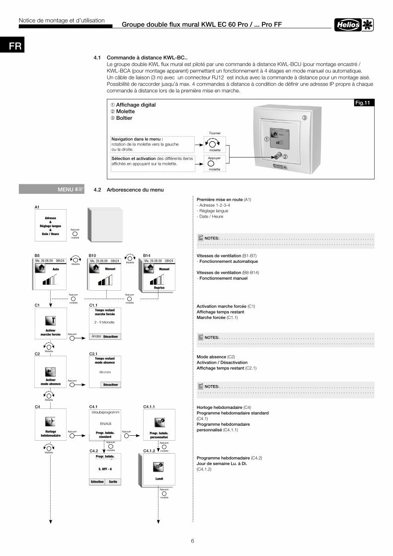
6
Groupe double flux mural KWL EC 60 Pro / . . . Pro FFNotice de montage et d’utilisation
4 .1 Commande à distance KWL-BC . . Le groupe double KWL flux mural est piloté par une commande à distance KWL-BCU (pour montage encastré / KWL-BCA (pour montage apparent) permettant un fonctionnement à 4 étages en mode manuel ou automatique. Un câble de liaison (3 m) avec un connecteur RJ12 est inclus avec la commande à distance pour un montage aisé. Possibilité de raccorder jusqu’à max. 4 commandes à distance à condition de définir une adresse IP propre à chaque commande à distance lors de la première mise en marche.
4 .2 Arborescence du menu
â
ê
ô
â Affichage digitalê Molette ô Boîtier
Navigation dans le menu : rotation de la molette vers la gauche ou la droite.
Sélection et activation des différents items affichés en appuyant sur la molette.
Première mise en route (A1)- Adresse 1-2-3-4- Réglage langue- Date / Heure
Vitesses de ventilation (B1-B7) - Fonctionnement automatique Vitesses de ventilation (B8-B14) - Fonctionnement manuel
Activation marche forcée (C1)Affichage temps restant Marche forcée (C1.1)
Mode absence (C2) Activation / Désactivation Affichage temps restant (C2.1)
Horloge hebdomadaire (C4)Programme hebdomadaire standard (C4.1)Programme hebdomadaire personnalisé (C4.1.1)
Programme hebdomadaire (C4.2)Jour de semaine Lu . à Di . (C4.1.2)
MENU +
�NOTES: . . . . . . . . . . . . . . . . . . . . . . . . . . . . . . . . . . . . . . . . . . . . . . . . . . . . . . . . . . . . . . . . . . . . . . . . . . . . . . . . . . . . . . . . . . . . . . . . . . . . . . . . . . . . . . . . . . . . . . . . . . . . . . . . . . . . . . . . . . .
�NOTES: . . . . . . . . . . . . . . . . . . . . . . . . . . . . . . . . . . . . . . . . . . . . . . . . . . . . . . . . . . . . . . . . . . . . . . . . . . . . . . . . . . . . . . . . . . . . . . . . . . . . . . . . . . . . . . . . . . . . . . . . . . . . . . . . . . . . . . . . . . .
A1
C1 C1 .1
B5 B10 B14
C2 C2 .1
C4 C4 .1
C4 .2
C4 .1 .1
�NOTES: . . . . . . . . . . . . . . . . . . . . . . . . . . . . . . . . . . . . . . . . . . . . . . . . . . . . . . . . . . . . . . . . . . . . . . . . . . . . . . . . . . . . . . . . . . . . . . . . . . . . . . . . . . . . . . . . . . . . . . . . . . . . . . . . . . . . . . . . . . .
C4 .1 .2
Fig .11
Tourner
molette
Adresse&
Réglage langue&
Date / Heure
Me. 26.08.09 08h24 Me. 26.08.09 08h24 Me. 26.08.09 08h24
Auto Manuel Manuel
Reprise
Activer marche forcée
Temps restant marche forcée
Désactiver
Activer mode absence
Temps restantmode absence
Désactiver
Horloge hebdomadaire
Progr. hebdo.standard
Progr. hebdo.personnalisé
Progr. hebdo.
S. OFF - 6
Sélection SortieLundi
Appuyer
molette
FR
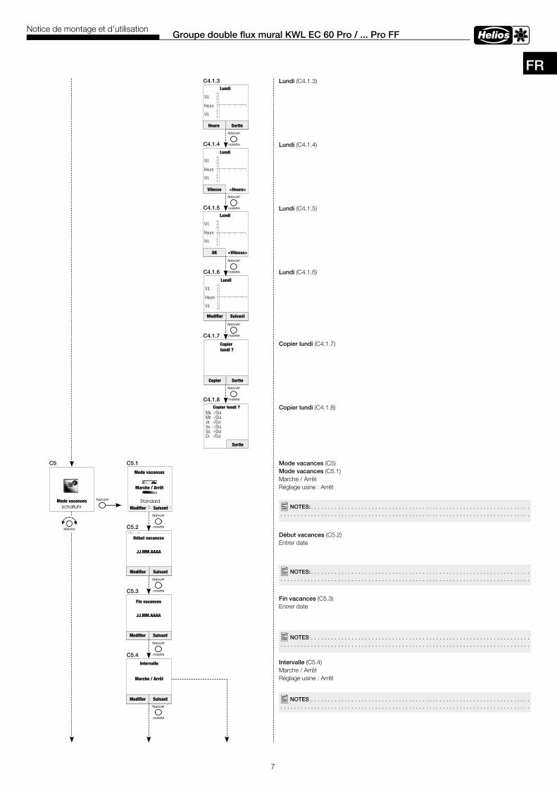
7
Groupe double flux mural KWL EC 60 Pro / . . . Pro FFNotice de montage et d’utilisation
Lundi (C4.1.3)
Lundi (C4.1.4)
Lundi (C4.1.5)
Lundi (C4.1.6)
Copier lundi (C4.1.7)
Copier lundi (C4.1.8)
Mode vacances (C5) Mode vacances (C5.1)Marche / Arrêt Réglage usine : Arrêt
Début vacances (C5.2) Entrer date
Fin vacances (C5.3) Entrer date
Intervalle (C5.4)Marche / ArrêtRéglage usine : Arrêt
C5 C5 .1
C4 .1 .3
C5 .2
C5 .3
C5 .4
C4 .1 .4
C4 .1 .5
C4 .1 .6
C4 .1 .7
C4 .1 .8
�NOTES: . . . . . . . . . . . . . . . . . . . . . . . . . . . . . . . . . . . . . . . . . . . . . . . . . . . . . . . . . . . . . . . . . . . . . . . . . . . . . . . . . . . . . . . . . . . . . . . . . . . . . . . . . . . . . . . . . . . . . . . . . . . . . . . . . . . . . . . . . . .
�NOTES: . . . . . . . . . . . . . . . . . . . . . . . . . . . . . . . . . . . . . . . . . . . . . . . . . . . . . . . . . . . . . . . . . . . . . . . . . . . . . . . . . . . . . . . . . . . . . . . . . . . . . . . . . . . . . . . . . . . . . . . . . . . . . . . . . . . . . . . . . . .
�NOTES . . . . . . . . . . . . . . . . . . . . . . . . . . . . . . . . . . . . . . . . . . . . . . . . . . . . . . . . . . . . . . . . . . . . . . . . . . . . . . . . . . . . . . . . . . . . . . . . . . . . . . . . . . . . . . . . . . . . . . . . . . . . . . . . . . . . . . . . . . .
�NOTES . . . . . . . . . . . . . . . . . . . . . . . . . . . . . . . . . . . . . . . . . . . . . . . . . . . . . . . . . . . . . . . . . . . . . . . . . . . . . . . . . . . . . . . . . . . . . . . . . . . . . . . . . . . . . . . . . . . . . . . . . . . . . . . . . . . . . . . . . . .
Lundi
Vit.
Heure
Vit.
Heure Sortie
Lundi
Vit.
Heure
Vit.
Vitesse <Heure>
Lundi
Vit.
Heure
Vit.
OK <Vitesse>
Lundi
Vit.
Heure
Vit.
Modifier Suivant
Copier lundi ?
Copier Sortie
Copier lundi ? Ma. -/OuiMe. -/OuiJe. -/OuiVe. - /OuiSa. -/OuiDi. -/Oui
Sortie
Mode vacances
Mode vacances
Marche / Arrêt
Modifier Suivant
Début vacances
JJ.MM.AAAA
Modifier Suivant
Fin vacances
JJ.MM.AAAA
Modifier Suivant
Intervalle
Marche / Arrêt
Modifier Suivant
FR
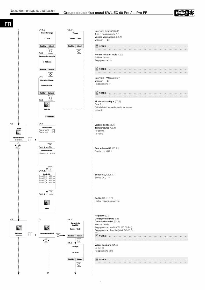
8
Groupe double flux mural KWL EC 60 Pro / . . . Pro FFNotice de montage et d’utilisation
Intervalle temps(C5.5.2)1-24 h Réglage usine 1 hVitesse ventilation (C5.5.1)Vitesse 1 - REP
Horaire mise en route (C5.6)5-180 minutesRéglage usine : 5
Intervalle - Vitesse (C5.7)Vitesse 1 - REPRéglage usine : 1
Mode automatique (C5.8)Date fin Est affichée lorsque le mode vacances est actif.
Valeurs sondes (C6)Températures (C6.1)Air soufflé Air rejeté
Sonde humidité (C6.1.1)Sonde humidité 1
Sonde C02(C6.1.1.1)Sonde CO2 1-4
Sortie (C6.1.1.1.1)Quitter consignes sondes
Réglages (C7)Consigne humidité (D1)Contrôle humidité (D1.1)Marche / ArrêtRéglage usine : Arrêt (KWL EC 60 Pro)Réglage usine : Marche (KWL EC 60 Pro FF)
Valeur consigne (D1.2)00 % HR Réglage usine : 60
C5 .5 .2 C5 .5 .1
C5 .6
C5 .7
C5 .8
�NOTES: . . . . . . . . . . . . . . . . . . . . . . . . . . . . . . . . . . . . . . . . . . . . . . . . . . . . . . . . . . . . . . . . . . . . . . . . . . . . . . . . . . . . . . . . . . . . . . . . . . . . . . . . . . . . . . . . . . . . . . . . . . . . . . . . . . . . . . . . . . .
C6 C6 .1
C6 .1 .1
C6 .1 .1 .1
C6 .1 .1 .1 .1
C7 D1 D1 .1
D1 .2
�NOTES: . . . . . . . . . . . . . . . . . . . . . . . . . . . . . . . . . . . . . . . . . . . . . . . . . . . . . . . . . . . . . . . . . . . . . . . . . . . . . . . . . . . . . . . . . . . . . . . . . . . . . . . . . . . . . . . . . . . . . . . . . . . . . . . . . . . . . . . . . . .
�NOTES: . . . . . . . . . . . . . . . . . . . . . . . . . . . . . . . . . . . . . . . . . . . . . . . . . . . . . . . . . . . . . . . . . . . . . . . . . . . . . . . . . . . . . . . . . . . . . . . . . . . . . . . . . . . . . . . . . . . . . . . . . . . . . . . . . . . . . . . . . . .
�NOTES: . . . . . . . . . . . . . . . . . . . . . . . . . . . . . . . . . . . . . . . . . . . . . . . . . . . . . . . . . . . . . . . . . . . . . . . . . . . . . . . . . . . . . . . . . . . . . . . . . . . . . . . . . . . . . . . . . . . . . . . . . . . . . . . . . . . . . . . . . . .
�NOTES: . . . . . . . . . . . . . . . . . . . . . . . . . . . . . . . . . . . . . . . . . . . . . . . . . . . . . . . . . . . . . . . . . . . . . . . . . . . . . . . . . . . . . . . . . . . . . . . . . . . . . . . . . . . . . . . . . . . . . . . . . . . . . . . . . . . . . . . . . . .
Intervalle temps
1 - 24 h
Modifier Suivant Modifier Suivant
Horaire mise en route
5 - 180 min.
Modifier Suivant
Modifier Suivant
Modifier Suivant
Modifier Suivant
Consigne
00 % HR
Vitesse
Vitesse 1 - REP
Intervalle - Vitesse
Vitesse 1 - REP
Date fin
Désactiver
Valeurs sondes
Sonde Températures
Temp. air soufflé 00°CTemp. air rejeté 00°C
Sonde humidité
Sonde humi. 1 00% HR
Sonde CO2Sonde CO2 1 0000 ppmSonde CO2 2 0000 ppmSonde CO2 3 0000 ppmSonde CO2 4 0000 ppm
Sortie
Réglages Consigne humidité
Etat contrôle humidité
Marche / Arrêt
FR

9
Groupe double flux mural KWL EC 60 Pro / . . . Pro FFNotice de montage et d’utilisation
Etages commutation (D1.3)00 % HRRéglage usine : 10
Post-ventilation (D1.4)1-4 heuresRéglage usine : 2
Consigne CO2 (D2)Etat valeur consigne CO2 (D2.1)Marche / ArrêtRéglage usine : Arrêt (KWL EC 60 Pro et KWL EC 60 Pro FF)
Consigne (D2.2)0000 ppm
Etage de commutation (D2.3)0000 ppm
Post-ventilation (D2.4) 1-4 heuresRéglage usine : 0
Marche forcée (D3)Durée (D3.1)1-180 minutesRéglage usine : 120
Vitesse de ventilation (D3.2)Vitesse 1 - REPRéglage usine : 4
Mode absence (D4)Durée (D4.1)1-180 minutesRéglage usine : 120
Vitesse de ventilation (D4.2)Vitesse 0 -1 Réglage usine : 0
D1 .3
D1 .4
D2 D2 .1
D3 D3 .1
D2 .2
D2 .3
D2 .4
D4 .2
D3 .2
D4 .1D4
�NOTES: . . . . . . . . . . . . . . . . . . . . . . . . . . . . . . . . . . . . . . . . . . . . . . . . . . . . . . . . . . . . . . . . . . . . . . . . . . . . . . . . . . . . . . . . . . . . . . . . . . . . . . . . . . . . . . . . . . . . . . . . . . . . . . . . . . . . . . . . . . .
�NOTES: . . . . . . . . . . . . . . . . . . . . . . . . . . . . . . . . . . . . . . . . . . . . . . . . . . . . . . . . . . . . . . . . . . . . . . . . . . . . . . . . . . . . . . . . . . . . . . . . . . . . . . . . . . . . . . . . . . . . . . . . . . . . . . . . . . . . . . . . . . .
�NOTES: . . . . . . . . . . . . . . . . . . . . . . . . . . . . . . . . . . . . . . . . . . . . . . . . . . . . . . . . . . . . . . . . . . . . . . . . . . . . . . . . . . . . . . . . . . . . . . . . . . . . . . . . . . . . . . . . . . . . . . . . . . . . . . . . . . . . . . . . . . .
�NOTES: . . . . . . . . . . . . . . . . . . . . . . . . . . . . . . . . . . . . . . . . . . . . . . . . . . . . . . . . . . . . . . . . . . . . . . . . . . . . . . . . . . . . . . . . . . . . . . . . . . . . . . . . . . . . . . . . . . . . . . . . . . . . . . . . . . . . . . . . . . .
�NOTES: . . . . . . . . . . . . . . . . . . . . . . . . . . . . . . . . . . . . . . . . . . . . . . . . . . . . . . . . . . . . . . . . . . . . . . . . . . . . . . . . . . . . . . . . . . . . . . . . . . . . . . . . . . . . . . . . . . . . . . . . . . . . . . . . . . . . . . . . . . .
Modifier Suivant
Etages commutation
00 % HR
Modifier Sortie
Modifier Suivant
Modifier Suivant
Modifier Suivant
Modifier Sortie
Modifier Suivant
Modifier Suivant
Modifier Suivant
Post-ventilation
1- 4 h
Consigne CO2
Etat consigne CO2
Marche / Arrêt
Consigne
Etages commutation
Post-ventilation
1- 4 h
Marche forcée
Durée
1 - 180 min.
Vitesse
Vitesse 1 - REP
Mode absence
Durée
1 - 180 min.
Vitesse
Vitesse 0 - 1
Modifier Sortie
FR
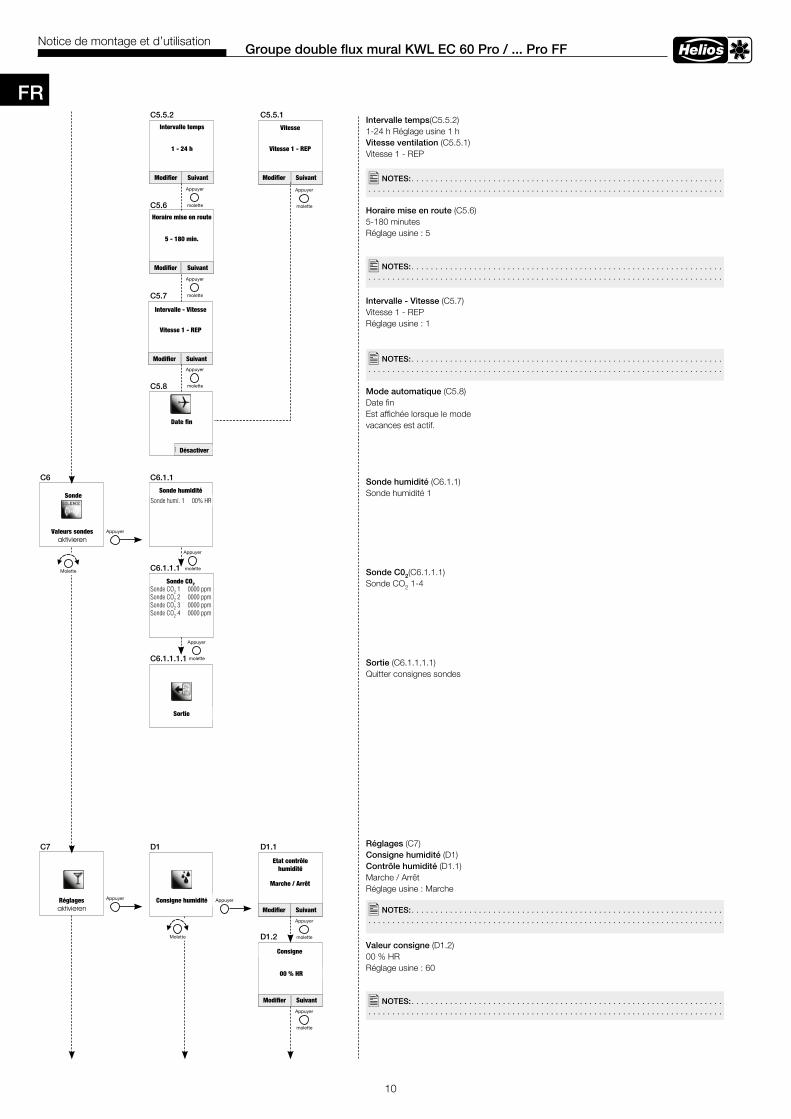
10
Groupe double flux mural KWL EC 60 Pro / . . . Pro FFNotice de montage et d’utilisation
Intervalle temps(C5.5.2)1-24 h Réglage usine 1 hVitesse ventilation (C5.5.1)Vitesse 1 - REP
Horaire mise en route (C5.6)5-180 minutesRéglage usine : 5
Intervalle - Vitesse (C5.7)Vitesse 1 - REPRéglage usine : 1
Mode automatique (C5.8)Date fin Est affichée lorsque le mode vacances est actif.
Sonde humidité (C6.1.1)Sonde humidité 1
Sonde C02(C6.1.1.1)Sonde CO2 1-4
Sortie (C6.1.1.1.1)Quitter consignes sondes
Réglages (C7)Consigne humidité (D1)Contrôle humidité (D1.1)Marche / ArrêtRéglage usine : Marche
Valeur consigne (D1.2)00 % HR Réglage usine : 60
C5 .5 .2 C5 .5 .1
C5 .6
C5 .7
C5 .8
�NOTES: . . . . . . . . . . . . . . . . . . . . . . . . . . . . . . . . . . . . . . . . . . . . . . . . . . . . . . . . . . . . . . . . . . . . . . . . . . . . . . . . . . . . . . . . . . . . . . . . . . . . . . . . . . . . . . . . . . . . . . . . . . . . . . . . . . . . . . . . . . .
C6 C6 .1 .1
C6 .1 .1 .1
C6 .1 .1 .1 .1
C7 D1 D1 .1
D1 .2
�NOTES: . . . . . . . . . . . . . . . . . . . . . . . . . . . . . . . . . . . . . . . . . . . . . . . . . . . . . . . . . . . . . . . . . . . . . . . . . . . . . . . . . . . . . . . . . . . . . . . . . . . . . . . . . . . . . . . . . . . . . . . . . . . . . . . . . . . . . . . . . . .
�NOTES: . . . . . . . . . . . . . . . . . . . . . . . . . . . . . . . . . . . . . . . . . . . . . . . . . . . . . . . . . . . . . . . . . . . . . . . . . . . . . . . . . . . . . . . . . . . . . . . . . . . . . . . . . . . . . . . . . . . . . . . . . . . . . . . . . . . . . . . . . . .
�NOTES: . . . . . . . . . . . . . . . . . . . . . . . . . . . . . . . . . . . . . . . . . . . . . . . . . . . . . . . . . . . . . . . . . . . . . . . . . . . . . . . . . . . . . . . . . . . . . . . . . . . . . . . . . . . . . . . . . . . . . . . . . . . . . . . . . . . . . . . . . . .
�NOTES: . . . . . . . . . . . . . . . . . . . . . . . . . . . . . . . . . . . . . . . . . . . . . . . . . . . . . . . . . . . . . . . . . . . . . . . . . . . . . . . . . . . . . . . . . . . . . . . . . . . . . . . . . . . . . . . . . . . . . . . . . . . . . . . . . . . . . . . . . . .
Intervalle temps
1 - 24 h
Modifier Suivant
Vitesse
Vitesse 1 - REP
Modifier Suivant
Horaire mise en route
5 - 180 min.
Modifier Suivant
Intervalle - Vitesse
Vitesse 1 - REP
Modifier Suivant
Date fin
Désactiver
Valeurs sondes
SondeSonde humidité
Sonde humi. 1 00% HR
Sonde CO2Sonde CO2 1 0000 ppmSonde CO2 2 0000 ppmSonde CO2 3 0000 ppmSonde CO2 4 0000 ppm
Sortie
Réglages Consigne humidité
Etat contrôle humidité
Marche / Arrêt
Modifier Suivant
Modifier Suivant
Consigne
00 % HR
FR
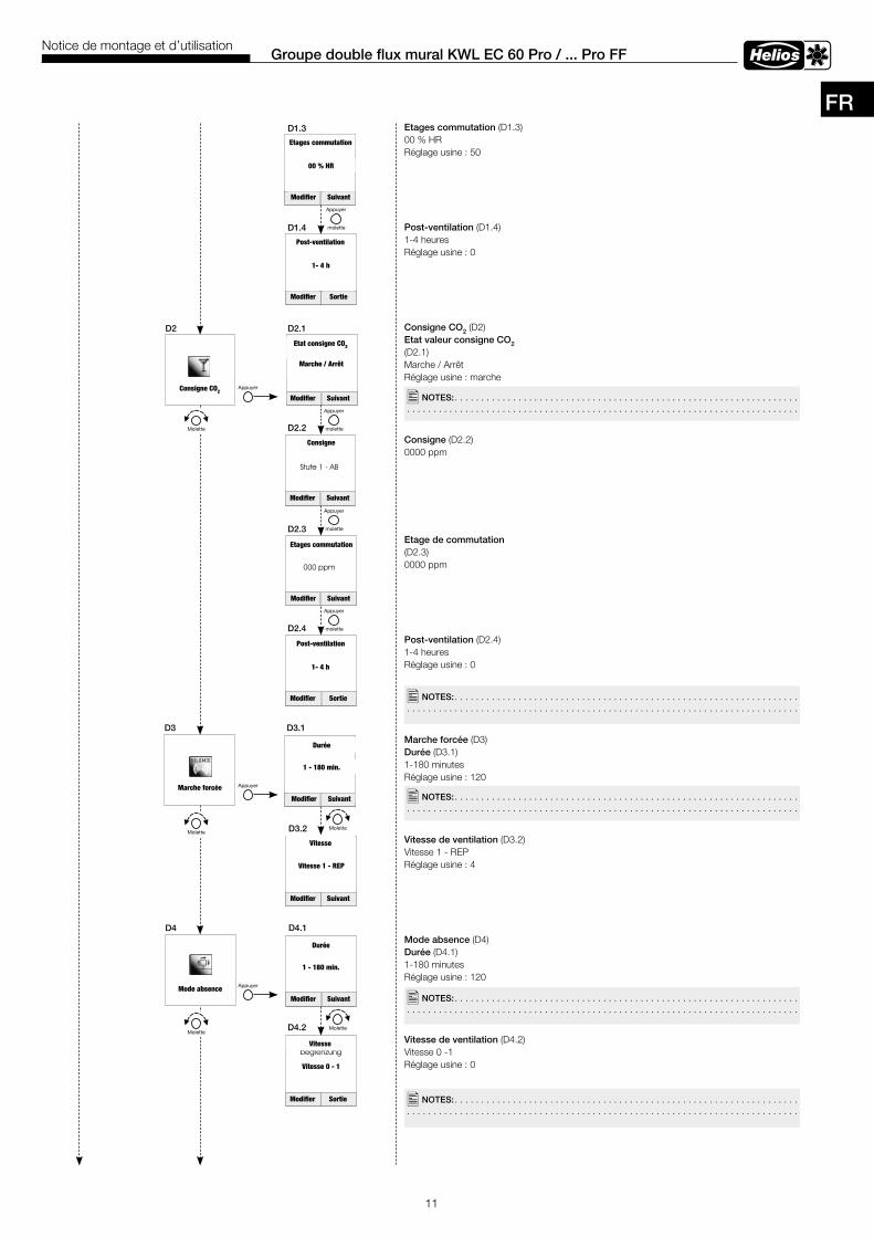
11
Groupe double flux mural KWL EC 60 Pro / . . . Pro FFNotice de montage et d’utilisation
Etages commutation (D1.3)00 % HRRéglage usine : 50
Post-ventilation (D1.4)1-4 heuresRéglage usine : 0
Consigne CO2 (D2)Etat valeur consigne CO2 (D2.1)Marche / ArrêtRéglage usine : marche
Consigne (D2.2)0000 ppm
Etage de commutation (D2.3)0000 ppm
Post-ventilation (D2.4) 1-4 heuresRéglage usine : 0
Marche forcée (D3)Durée (D3.1)1-180 minutesRéglage usine : 120
Vitesse de ventilation (D3.2)Vitesse 1 - REPRéglage usine : 4
Mode absence (D4)Durée (D4.1)1-180 minutesRéglage usine : 120
Vitesse de ventilation (D4.2)Vitesse 0 -1 Réglage usine : 0
D1 .3
D1 .4
D2 D2 .1
D3 D3 .1
D2 .2
D2 .3
D2 .4
D4 .2
D3 .2
D4 .1D4
�NOTES: . . . . . . . . . . . . . . . . . . . . . . . . . . . . . . . . . . . . . . . . . . . . . . . . . . . . . . . . . . . . . . . . . . . . . . . . . . . . . . . . . . . . . . . . . . . . . . . . . . . . . . . . . . . . . . . . . . . . . . . . . . . . . . . . . . . . . . . . . . .
�NOTES: . . . . . . . . . . . . . . . . . . . . . . . . . . . . . . . . . . . . . . . . . . . . . . . . . . . . . . . . . . . . . . . . . . . . . . . . . . . . . . . . . . . . . . . . . . . . . . . . . . . . . . . . . . . . . . . . . . . . . . . . . . . . . . . . . . . . . . . . . . .
�NOTES: . . . . . . . . . . . . . . . . . . . . . . . . . . . . . . . . . . . . . . . . . . . . . . . . . . . . . . . . . . . . . . . . . . . . . . . . . . . . . . . . . . . . . . . . . . . . . . . . . . . . . . . . . . . . . . . . . . . . . . . . . . . . . . . . . . . . . . . . . . .
�NOTES: . . . . . . . . . . . . . . . . . . . . . . . . . . . . . . . . . . . . . . . . . . . . . . . . . . . . . . . . . . . . . . . . . . . . . . . . . . . . . . . . . . . . . . . . . . . . . . . . . . . . . . . . . . . . . . . . . . . . . . . . . . . . . . . . . . . . . . . . . . .
�NOTES: . . . . . . . . . . . . . . . . . . . . . . . . . . . . . . . . . . . . . . . . . . . . . . . . . . . . . . . . . . . . . . . . . . . . . . . . . . . . . . . . . . . . . . . . . . . . . . . . . . . . . . . . . . . . . . . . . . . . . . . . . . . . . . . . . . . . . . . . . . .
Modifier Suivant
Etages commutation
00 % HR
Modifier Sortie
Post-ventilation
1- 4 h
Consigne CO2
Etat consigne CO2
Marche / Arrêt
Modifier Suivant
Consigne
Modifier Suivant
Modifier Suivant
Etages commutation
Modifier Sortie
Post-ventilation
1- 4 h
Marche forcée
Durée
1 - 180 min.
Modifier Suivant
Vitesse
Vitesse 1 - REP
Modifier Suivant
Mode absence
Durée
1 - 180 min.
Modifier Suivant
Vitesse
Vitesse 0 - 1
Modifier Sortie
FR
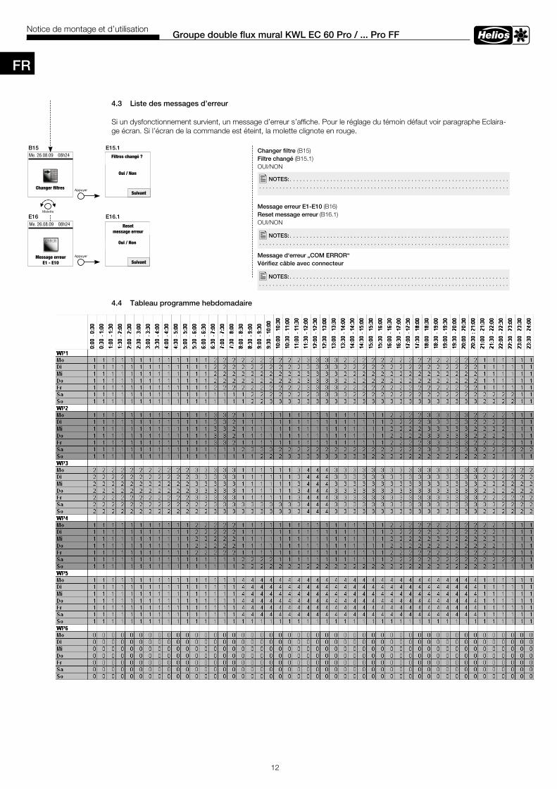
12
Groupe double flux mural KWL EC 60 Pro / . . . Pro FFNotice de montage et d’utilisation
4 .3 Liste des messages d’erreur
Si un dysfonctionnement survient, un message d’erreur s’affiche. Pour le réglage du témoin défaut voir paragraphe Eclaira-ge écran. Si l’écran de la commande est éteint, la molette clignote en rouge.
4 .4 Tableau programme hebdomadaire
Changer filtre (B15)Filtre changé (B15.1)OUI/NON
Message erreur E1-E10 (B16)Reset message erreur (B16.1)OUI/NON
Message d‘erreur „COM ERROR“Vérifiez câble avec connecteur
�NOTES: . . . . . . . . . . . . . . . . . . . . . . . . . . . . . . . . . . . . . . . . . . . . . . . . . . . . . . . . . . . . . . . . . . . . . . . . . . . . . . . . . . . . . . . . . . . . . . . . . . . . . . . . . . . . . . . . . . . . . . . . . . . . . . . . . . . . . . . . . . .
�NOTES: . . . . . . . . . . . . . . . . . . . . . . . . . . . . . . . . . . . . . . . . . . . . . . . . . . . . . . . . . . . . . . . . . . . . . . . . . . . . . . . . . . . . . . . . . . . . . . . . . . . . . . . . . . . . . . . . . . . . . . . . . . . . . . . . . . . . . . . . . . .
�NOTES: . . . . . . . . . . . . . . . . . . . . . . . . . . . . . . . . . . . . . . . . . . . . . . . . . . . . . . . . . . . . . . . . . . . . . . . . . . . . . . . . . . . . . . . . . . . . . . . . . . . . . . . . . . . . . . . . . . . . . . . . . . . . . . . . . . . . . . . . . . .
B15 E15 .1
E16 E16 .1
Me. 26.08.09 08h24
Changer filtres
Filtres changé ?
Oui / Non
Suivant
Me. 26.08.09 08h24
SuivantMessage erreur
E1 - E10
Reset message erreur
Oui / Non
FR
12
Wand-Einbaugerät KWL EC 60 Pro / ... Pro FFMontage- und Betriebsvorschrift
Luftfilter wechseln (B15)Luftfilter gewechselt (B15.1)JA/NEIN
Fehlermeldung E1-E10 (B16)Fehlermeldung rücksetzen(B16.1)JA/NEIN
4.3 Fehlermenü/Fehleranzeige im Display
Bei einem Fehler wird die Fehlermeldung angezeigt, Leuchtdauer siehe Displaybeleuchtung.Ist das Display aus, blinkt der Drehencoder rot!
4.4 Tabelle: Wochenprogramm
B15 E15.1
E16 E16.1
�NOTIZEN: . . . . . . . . . . . . . . . . . . . . . . . . . . . . . . . . . . . . . . . . . . . . . . . . . . . . . . . . . . . . . . .
�NOTIZEN: . . . . . . . . . . . . . . . . . . . . . . . . . . . . . . . . . . . . . . . . . . . . . . . . . . . . . . . . . . . . . . .
D
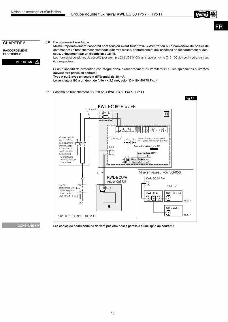
13
Groupe double flux mural KWL EC 60 Pro / . . . Pro FFNotice de montage et d’utilisation
5 .0 Raccordement électrique Mettre impérativement l’appareil hors tension avant tous travaux d’entretien ou à l’ouverture du boîtier de commande! Le branchement électrique doit être réalisé, conformément aux schémas de raccordement ci-des-sous, uniquement par un électricien qualifié .Les normes et consignes de sécurité (par exemple DIN VDE 0100), ainsi que la norme C15 100 doivent impérativement être respectées.
Si un dispositif de protection est intégré dans le raccordement du ventilateur EC, les spécificités suivantes doivent être prises en compte :Type A ou B avec un courant différentiel de 30 mA .Le ventilateur EC a un débit de fuite <= 3,5 mA, selon DIN EN 50178 Fig . 4 .
5 .1 Schéma de branchement SS-950 pour KWL EC 60 Pro / . . . Pro FF
Les câbles de commande ne doivent pas être posés parallèle à une ligne de courant !
CHAPITRE 5
RACCORDEMENT ELECTRIQUE
IMPORTANT m
KWL EC 60 Pro / FF
L1 N
Optional:Bauseitiger
On/off switchTrennschalter /
VDE 0700 T1 7.12.2
Signal der Sicherheits-einrichtung, siehe
MBV-Montage undBetriebsvorschrift
Optional:Bauseits beiRaumluft-abhängigenFeuerstättenzu erstellen !
L
N
2 x 1,5mm²
85123 002 SS-950 10.02.11
KWL-BCU/AArt.Nr. 9955/6
L N LA N LZ N TR-PR
ITR
-PRI
TR-SE
CTR
-SEC
+ AB - + ZU -
HumiT100mA/250V
RJ12
RJ12
6
KWL EC 60 Pro
KWL-ALA KWL-BCU/A
KWL-CO2
max. 4
max. 4
off
on1 2
Vernetzung, siehe SS-958 !
FS Humi = Feuchte-Fühler, Type FFFS = Frostschutz-Fühler, Sonder
Feuchte-Fühler, Type FF
max. 10
DIP-Schalter1 2
Master off onSlave on off
Fig .12
Option : à réali-ser en présen-ce d’appareils de chauffage à foyer atmo-sphérique (four-niture client)
Sonde humidité, type FF
Option : sectionneur On/Off/switch (four-niture client)
Signal foyers atmosphériques, voir notice
Humi = Sonde humidité, type FFFS = Sonde anti-gel, hors standard
Esclave
Maître
Interrupteur DIP
Mise en réseau, voir SS-958
CONSIGNE +
FR
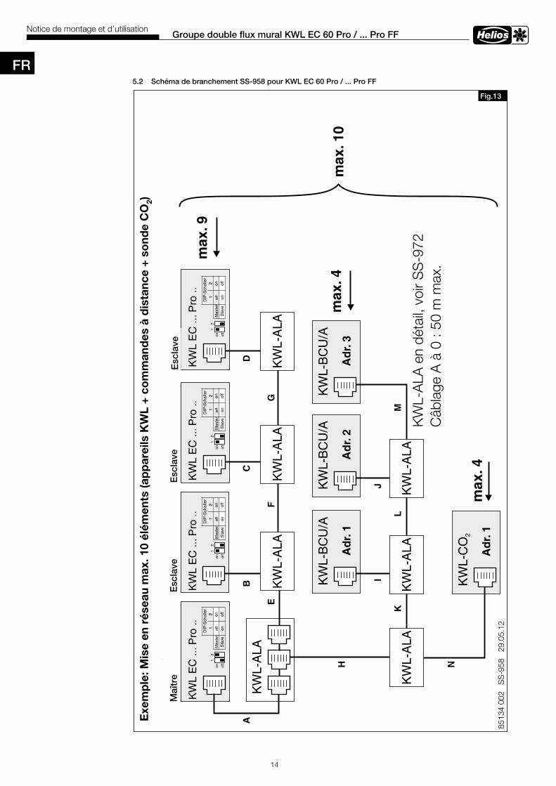
14
Groupe double flux mural KWL EC 60 Pro / . . . Pro FFNotice de montage et d’utilisation
5 .2 Schéma de branchement SS-958 pour KWL EC 60 Pro / . . . Pro FF
Fig .13
8513
4 00
2 S
S-9
58
29.0
5.12
KW
L-B
CU
/A
Ad
r.1
KW
L E
C ..
.Pro
..
KW
L-A
LA
KW
L-C
O2
max
.4
max
.4A
dr.
1
Bei
spie
l:V
erne
tzun
g K
WL
EC
60
Pro
, max
.10
Teiln
ehm
er (
Ger
äte
+ B
edie
nele
men
te +
CO
-F
ühle
r)2
KW
L-B
CU
/A
Ad
r.2
KW
L-B
CU
/A
Ad
r.3
KW
L-A
LAK
WL-
ALA
KW
L-A
LA
KW
L-A
LAK
WL-
ALA
KW
L-A
LA
AB
CD
EF
G
H
IJ
KL
M
NLe
itung
en A
bis
N,
insg
esam
t max
.50m
KW
L E
C ..
.Pro
..K
WL
EC
...P
ro ..
KW
L E
C ..
.Pro
..
Mas
ter
Sla
veS
lave
Sla
ve
max
.10
KW
L-A
LA im
Det
ail,
sieh
e S
S-9
72
off
on1
2
DIP
-Sch
alte
r1
2M
aste
rof
fon
Sla
veon
off
off
on1
2
DIP
-Sch
alte
r1
2M
aste
rof
fon
Sla
veon
off
off
on1
2
DIP
-Sch
alte
r1
2M
aste
rof
fon
Sla
veon
off
off
on1
2
DIP
-Sch
alte
r1
2M
aste
rof
fon
Sla
veon
off
max
.9
Exe
mp
le: M
ise
en r
ésea
u m
ax. 1
0 él
émen
ts (a
pp
arei
ls K
WL
+ co
mm
and
es à
dis
tanc
e +
sond
e C
O2)
Maî
tre
Esc
lave
Esc
lave
Esc
lave
KW
L-A
LA e
n dé
tail,
voi
r SS
-972
Câb
lage
A à
0 :
50 m
max
.
FR
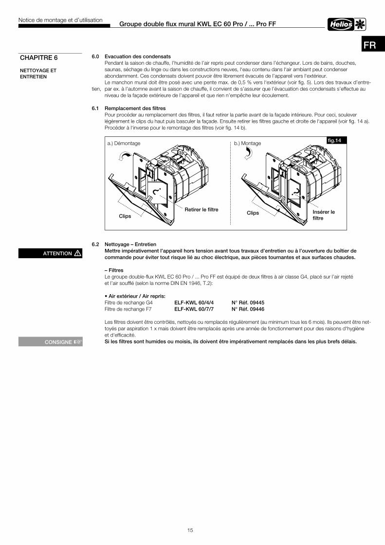
15
Groupe double flux mural KWL EC 60 Pro / . . . Pro FFNotice de montage et d’utilisation
6 .0 Evacuation des condensats Pendant la saison de chauffe, l’humidité de l’air repris peut condenser dans l’échangeur. Lors de bains, douches, saunas, séchage du linge ou dans les constructions neuves, l‘eau contenu dans l‘air ambiant peut condenser abondamment. Ces condensats doivent pouvoir être librement évacués de l’appareil vers l‘extérieur. Le manchon mural doit être posé avec une pente max. de 0,5 % vers l‘extérieur (voir fig. 5). Lors des travaux d’entre-tien, par ex. à l’automne avant la saison de chauffe, il convient de s’assurer que l’évacuation des condensats s’effectue au niveau de la façade extérieure de l’appareil et que rien n’empêche leur écoulement.
6 .1 Remplacement des filtres Pour procéder au remplacement des filtres, il faut retirer la partie avant de la façade intérieure. Pour ceci, soulever légèrement le clips du haut puis basculer la façade. Ensuite retirer les filtres gauche et droite de l‘appareil (voir fig. 14 a). Procéder à l‘inverse pour le remontage des filtres (voir fig. 14 b).
6 .2 Nettoyage – Entretien Mettre impérativement l’appareil hors tension avant tous travaux d’entretien ou à l’ouverture du boîtier de commande pour éviter tout risque lié au choc électrique, aux pièces tournantes et aux surfaces chaudes .
– Filtres Le groupe double-flux KWL EC 60 Pro / ... Pro FF est équipé de deux filtres à air classe G4, placé sur l’air rejeté et l’air soufflé (selon la norme DIN EN 1946, T.2): • Air extérieur / Air repris: Filtre de rechange G4 ELF-KWL 60/4/4 N° Réf . 09445 Filtre de rechange F7 ELF-KWL 60/7/7 N° Réf . 09446
Les filtres doivent être contrôlés, nettoyés ou remplacés régulièrement (au minimum tous les 6 mois). Ils peuvent être net-toyés par aspiration 1 x mais doivent être remplacés après une année de fonctionnement pour des raisons d‘hygiène et d‘efficacité.
Si les filtres sont humides ou moisis, ils doivent être impérativement remplacés dans les plus brefs délais .
CHAPITRE 6
NETTOYAGE ET ENTRETIEN
ATTENTION m
fig .14a.) Démontage b.) Montage
Retirer le filtreClips
? ?
Insérer le filtre
Clips
CONSIGNE +
FR
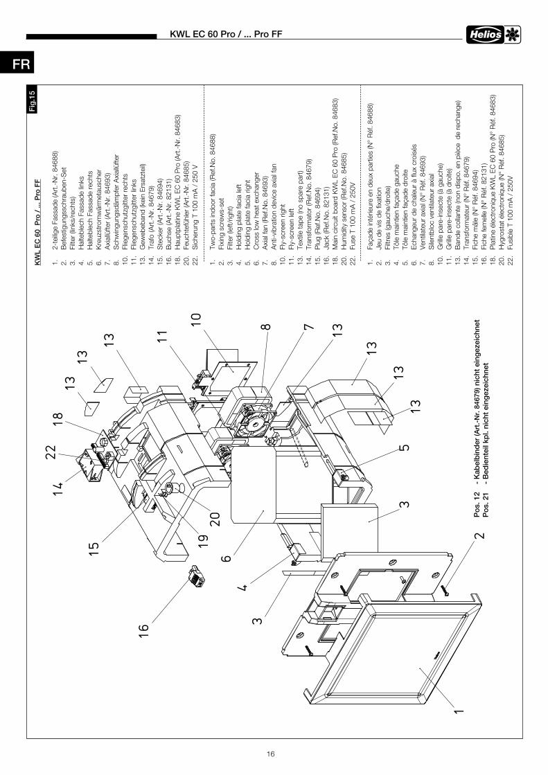
16
KWL EC 60 Pro / . . . Pro FF
6
78
4
5
10
11
1418
15
16
19
3
3
1
1313
13
13
1313
2P
os. 1
2 - K
abel
bind
er n
icht
ein
geze
ichn
etP
os. 2
1 - B
edie
ntei
l kpl
. nic
ht e
inge
zeic
hnet
13
20
22
Fig
.15
Po
s . 1
2
- K
abel
bin
der
(Art
.-N
r . 8
4679
) nic
ht e
ing
ezei
chne
tP
os .
21
- B
edie
ntei
l kp
l . ni
cht
eing
ezei
chne
t
KW
L E
C 6
0 P
ro /
. . . P
ro F
F
1.
2-te
ilige
Fass
ade
(Art
.-N
r. 84
688)
2.
Bef
estig
ungs
schr
aube
n-S
et3.
Fi
lter (
links
/rec
hts)
4.
Hal
tebl
ech
Fass
ade
links
5.
Hal
tebl
ech
Fass
ade
rech
ts6.
K
reuz
stro
mw
ärm
etau
sche
r7.
A
xial
lüfte
r (A
rt.-
Nr.
8469
3)8.
S
chw
ingu
ngsd
ämpf
er A
xial
lüfte
r10
. Fl
iege
nsch
utzg
itter
rech
ts11
. Fl
iege
nsch
utzg
itter
link
s13
. G
eweb
eban
d (k
ein
Ersa
tzte
il)14
. Tr
afo
(Art
.-N
r. 84
679)
15.
Ste
cker
(Art
.-N
r. 84
694)
16.
Buc
hse
(Art
.-N
r. 82
131)
18.
Hau
ptpl
atin
e K
WL
EC 6
0 P
ro (A
rt.-
Nr.
8468
3)20
. Fe
ucht
efüh
ler (
Art
.-N
r. 84
685)
22.
Sic
heru
ng T
100
mA
/ 2
50 V
1.
Two-
part
s in
door
faci
a (R
ef.N
o. 8
4688
)2.
Fi
scr
ews-
set
3.
Filte
r (le
ft/rig
ht)
4.
Hol
ding
pla
te fa
cia
left
5.
Hol
ding
pla
te fa
cia
right
6.
Cro
ss lo
w h
eat e
xcha
nger
7.
Axi
al fa
n (R
ef.N
o. 8
4693
)8.
A
nti-v
ibra
tion
devi
ce a
xial
fan
10.
Fly-
scre
en ri
ght
11.
Fly-
scre
en le
ft13
. Te
xtile
tape
(no
spar
e pa
rt)
14.
Tran
sfor
mat
or (R
ef.N
o. 8
4679
)15
. P
lug
(Ref
.No.
846
94)
16.
Jack
(Ref
.No.
821
31)
18.
Mai
n ci
rcui
t boa
rd K
WL
EC 6
0 P
ro (R
ef.N
o. 8
4683
)20
. H
umid
ity s
enso
r (R
ef.N
o. 8
4685
)22
. Fu
se T
100
mA
/ 2
50V
1.
Faça
de in
térie
ure
en d
eux
part
ies
(N°
Réf
. 846
88)
2.
Jeu
de v
is d
e fix
atio
n3.
Fi
ltres
(gau
che/
droi
te)
4.
Tôle
mai
ntie
n fa
çade
gau
che
5.
Tôle
mai
ntie
n fa
çade
dro
ite6.
Ec
hang
eur d
e ch
aleu
r à fl
ux c
rois
és7.
Ve
ntila
teur
axi
al (N
° R
éf. 8
4693
)8.
S
ilent
bloc
ven
tilat
eur a
xial
10
. G
rille
par
e-in
sect
e (à
gau
che)
11
. G
rille
par
e-in
sect
e (à
dro
ite)
13.
Ban
de c
olla
nte
(non
dis
po. e
n pi
èce
de
rech
ange
)14
. Tr
ansf
orm
ateu
r (N
° R
éf. 8
4679
)15
. Fi
che
mâl
e (N
° R
éf. 8
4694
)16
. Fi
che
fem
elle
(N°
Réf
. 821
31)
18.
Pla
tine
élec
tron
ique
KW
L EC
60
Pro
(N°
Réf
. 846
83)
20.
Hyg
rost
at é
lect
roni
que
(N°
Réf
. 846
85)
22.
Fusi
ble
T 10
0 m
A /
250
V
FR
17
KWL EC 60 Pro / . . . Pro FF
Notes:
FR

Service und InformationD HELIOS Ventilatoren GmbH + Co KG · Lupfenstraße 8 · 78056 VS-Schwenningen F HELIOS Ventilateurs · Le Carré des Aviateurs · 157 avenue Charles Floquet · 93155 Le Blanc Mesnil CedexCH HELIOS Ventilatoren AG · Tannstrasse 4 · 8112 Otelfingen GB HELIOS Ventilation Systems Ltd. · 5 Crown Gate · Wyncolls Road · Severalls Industrial Park · A HELIOS Ventilatoren · Postfach 854 · Siemensstraße 15 · 6023 Innsbruck Colchester · Essex · CO4 9HZ
www.heliosventilatoren.deAls Referenz am Gerät griffbereit aufbewahren! Druckschrift-Nr .Please keep this manual for reference with the unit! Print-No .:Conservez cette notice à proximité de l’apapreil! N° Réf . 86 666-001/1217