Embed Size (px)
Citation preview
Operating Manual
HD Visual Communication Unit
Model No. KX-VC300/KX-VC600
Document Version: 2011-10
In this manual, the suffix of each model number (e.g., KX-VC600NA) is omitted unless necessary.
Thank you for purchasing this Panasonic product.
Please read this manual carefully before using this product and save this manual for future use.
KX-VC300/KX-VC600: Software File Version 2.30 or later
Introduction
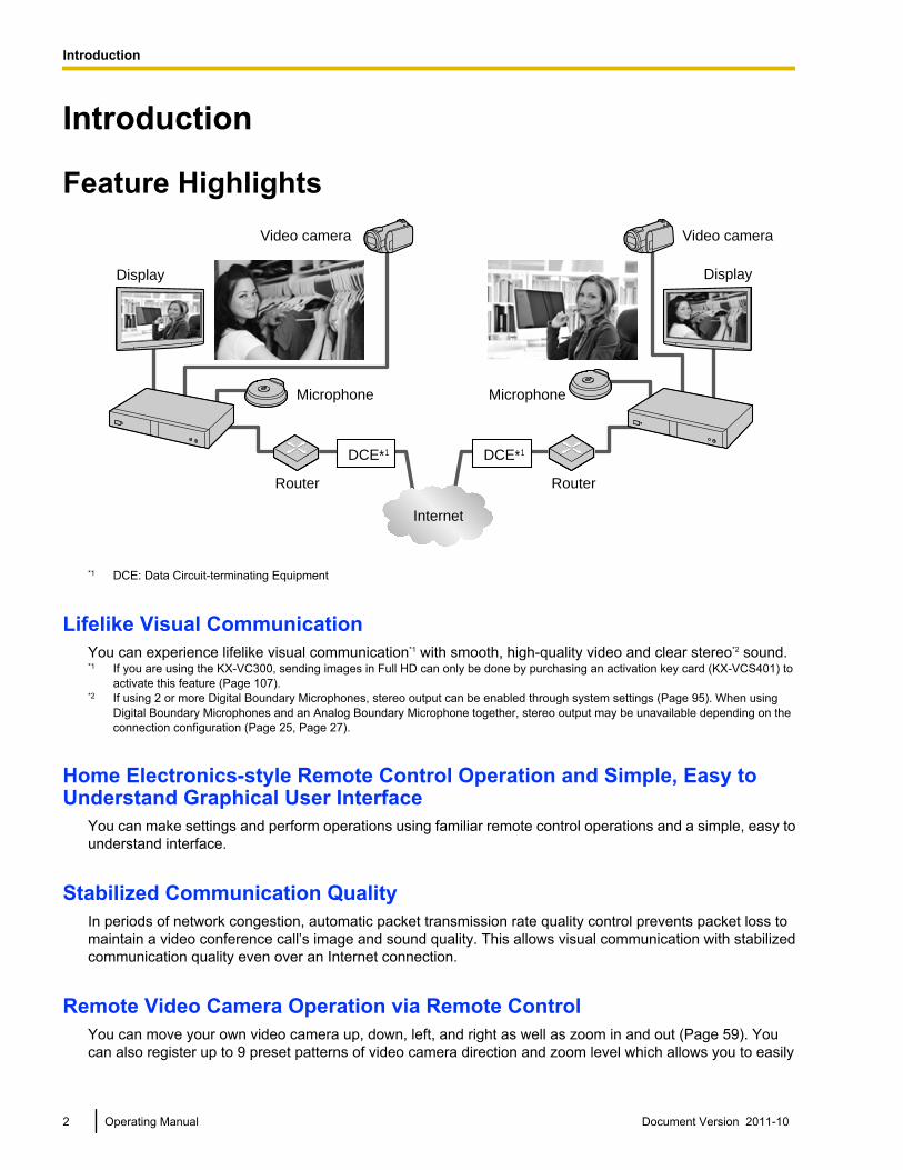
Feature Highlights
DCE*1 DCE*1
Video camera
Display
Microphone
Router
Internet
Router
Microphone
Video camera
Display
*1 DCE: Data Circuit-terminating Equipment
Lifelike Visual CommunicationYou can experience lifelike visual communication*1 with smooth, high-quality video and clear stereo*2 sound.*1 If you are using the KX-VC300, sending images in Full HD can only be done by purchasing an activation key card (KX-VCS401) to
activate this feature (Page 107).*2 If using 2 or more Digital Boundary Microphones, stereo output can be enabled through system settings (Page 95). When using
Digital Boundary Microphones and an Analog Boundary Microphone together, stereo output may be unavailable depending on theconnection configuration (Page 25, Page 27).
Home Electronics-style Remote Control Operation and Simple, Easy toUnderstand Graphical User Interface
You can make settings and perform operations using familiar remote control operations and a simple, easy tounderstand interface.
Stabilized Communication QualityIn periods of network congestion, automatic packet transmission rate quality control prevents packet loss tomaintain a video conference call’s image and sound quality. This allows visual communication with stabilizedcommunication quality even over an Internet connection.
Remote Video Camera Operation via Remote ControlYou can move your own video camera up, down, left, and right as well as zoom in and out (Page 59). Youcan also register up to 9 preset patterns of video camera direction and zoom level which allows you to easily
2 Operating Manual Document Version 2011-10
Introduction
change the video camera’s direction and zoom level by selecting a preset (Page 61, Page 63). Additionally,you can also use your remote control to control the other party’s video camera.*1
*1 To be able to control another party’s video camera, settings must be configured on the other party’s unit (Page 92).
Selectable Video SourceBy connecting your computer or video camera to the unit, you can show your computer’s screen or videocamera image to video conference call participants (Page 69, Page 76).
Encrypted CommunicationPackets sent for video conference calls can be encrypted to prevent packet leaks, tampering, oreavesdropping.
KX-VC Series NAT Traversal Service"KX-VC Series NAT Traversal Service" is a service that allows you to easily and affordably set up and operatea communication environment for the HD Visual Communication Unit.*1*2 Also, complicated router configurationis unnecessary, which allows even people who are not network administrators set up a communicationenvironment. Furthermore, you can assign the unit a unique number (Terminal ID), which allows the unit to becalled not by IP address, but with the unique 7-digit number. This means communication can be initiated as ifcalling a telephone. Communication can also be encrypted, so that you can communicate over the Internetsafely and securely.
For details about KX-VC Series NAT Traversal Service, refer to the following web site:http://panasonic.net/psn/products/hdvc/nat_traversal/index.html*1 This service may be unavailable depending on the country/area of use. For details, contact your dealer.*2 This service may be unavailable depending on your router’s type or your Internet connection environment. For details, contact your
dealer.
Making Video Conference Calls via SIP ServerBy using a SIP server, you can establish video conference calls not just by IP address, but also by specifyinga SIP URI (SIP user name@SIP domain name) instead. If the other party uses the same SIP domain nameas you, you can make a video conference call by specifying only the SIP user name (Page 105). For informationabout supported SIP servers, contact your dealer.
Enhanced Features through the Use of Activation KeysBy using an activation key (sold separately), you can upgrade the features of the KX-VC300 (Page 83). Afteryou upgrade the features, the KX-VC300 can initiate 3-party/4-party video conference calls and send imagesin Full HD resolution. Features enabled through activation keys are available even after performing a systeminitialization (Page 107). For details about the activation key, contact your dealer.
Connection to non-Panasonic Video Conference SystemsYou can connect to a non-Panasonic video conference system and have a 2-party video conference call(Page 48).*1
*1 For details about the types of non-Panasonic video conference systems you can connect to, contact your dealer. Communicationcannot be encrypted when you connect to a non-Panasonic video conference system. Instead, connect over an intranet or via a VPN(Virtual Private Network).
Document Version 2011-10 Operating Manual 3
Introduction
MCU ConnectionBy connecting to an MCU (multipoint control unit), you can make multiple-party video conference calls with 5or more parties, rather than the normal maximum of 4 parties (Page 49).*1
*1 For details about the types of MCUs you can connect to, contact your dealer. Communication cannot be encrypted when you connectto an MCU. Instead, connect over an intranet or via a VPN (Virtual Private Network).
4 Operating Manual Document Version 2011-10
Introduction
Trademarks• HDMI is a trademark or registered trademark of HDMI Licensing LLC in the United States and other
countries.• This product is licensed under the AVC Patent Portfolio License. This license permits the end user to
perform, for personal and non-commercial use, only the following actions:– Encode video in compliance with the AVC Standard (below, "AVC Video").– Decode AVC Video that was encoded by a consumer engaged in both personal and non-commercial
activity.– Decode AVC Video obtained from a video provider licensed to provide AVC Video.Additional information may be obtained from MPEG LA, LLC. See http://www.mpegla.com.
• All other trademarks identified herein are the property of their respective owners.
Open Source SoftwareParts of this product use Open Source Software supplied based on the conditions of the Free SoftwareFoundation’s GPLs and/or LGPLs and other conditions. Relevant conditions apply to this software. Therefore,please read license information about GPLs and LGPLs, and information about other Open Source Softwarein the included CD-ROM before using this product. Also, some software parts of this product are licensed underthe MOZILLA PUBLIC LICENSE (MPL). At least three (3) years from delivery of products, Panasonic will giveto any third party who contacts us at the contact information provided below, for a charge of no more than thecost of physically distributing source code, a complete machine-readable copy of the corresponding sourcecode and the copyright notices covered under GPL, LGPL, and MPL. Please note that software licensed underGPL, LGPL, and MPL is not under warranty.
Contact Informationhttp://www.panasonic.net/corporate/global_network/
MiscellaneousAbout the Screen Shots and Illustrations in this Manual
The screen shots, illustrations and descriptions in this manual are based on using the KX-VC600. If you areusing the KX-VC300, please note that some displayed features will not be available for your model.
Document Version 2011-10 Operating Manual 5
Introduction
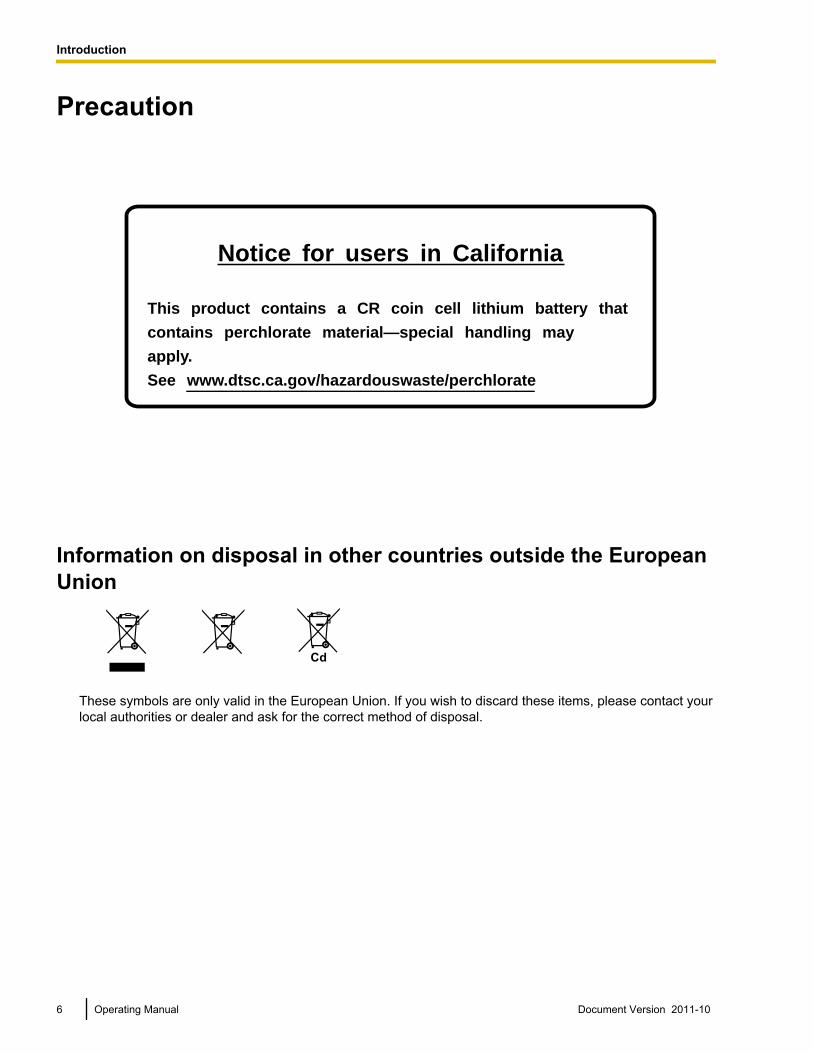
Precaution
Notice for users in California
This product contains a CR coin cell lithium battery that
contains perchlorate material—special handling may
apply.
See www.dtsc.ca.gov/hazardouswaste/perchlorate
Information on disposal in other countries outside the EuropeanUnion
These symbols are only valid in the European Union. If you wish to discard these items, please contact yourlocal authorities or dealer and ask for the correct method of disposal.
6 Operating Manual Document Version 2011-10
Introduction
Table of ContentsFor Your Safety ......................................................................................10
For Your Safety ...............................................................................................................10
Before Operation ....................................................................................14Notes about Operation ...................................................................................................14Data Security ...................................................................................................................15Privacy and Right of Publicity .......................................................................................15Federal Communications Commission Requirements ................................................16
Preparation .............................................................................................17Accessory Information ...................................................................................................17Part Names and Usage ...................................................................................................18
Main Unit (Front) ............................................................................................................18Main Unit (Back) .............................................................................................................19Remote Control ..............................................................................................................21Boundary Microphone (Optional Accessory) ..................................................................22LED Patterns ..................................................................................................................23Screen Standby ..............................................................................................................23
Connecting the Unit ........................................................................................................24Turning the Power On/Off ..............................................................................................30Screen Display ................................................................................................................31
Home Screen (Idle Screen) ............................................................................................31Menu Screen (Idle Screen) ............................................................................................32Video Conference Call Screen .......................................................................................34
Starting a Video Conference .................................................................36Making a Video Conference Call ....................................................................................36
Calling Using Speed Dial (2-party Conference/3-party Conference/4-partyConference) ....................................................................................................................36Calling from the Contact List (2-party Conference/3-party Conference/4-partyConference) ....................................................................................................................39Calling by Entering an Address Directly .........................................................................41Calling from the Call History ...........................................................................................44
Answering a Video Conference Call ..............................................................................47Connecting to a Non-Panasonic Video Conference System ......................................48Connecting to an MCU ....................................................................................................49
Changing the Screen Layout ................................................................51Changing the Screen Layout during a 2-party Video Conference Call ......................51Changing the Screen Layout during a 3-party Video Conference Call ......................53Changing the Screen Layout during a 4-party Video Conference Call ......................56
Controlling a PTZ Camera .....................................................................59Controlling a PTZ Camera ..............................................................................................59Registering a Preset .......................................................................................................61Recalling a Registered Preset ........................................................................................63
Adjusting the Volume and Tone ...........................................................64Adjusting the Volume .....................................................................................................64Muting the Microphone ...................................................................................................65Reducing Microphone Noise (KX-VC600 only) .............................................................67Adjusting the Tone ..........................................................................................................68
Document Version 2011-10 Operating Manual 7
Table of Contents
Displaying Other Video Sources ..........................................................69Displaying a Computer’s Screen ...................................................................................69Displaying the Sub Video Camera’s Image ..................................................................76
Displaying the Connection Status ........................................................80Displaying the Connection Status .................................................................................80Displaying Unit Information ...........................................................................................81
About Enhanced Features .....................................................................83Activating Enhanced Features .......................................................................................83
Overview of Activation Keys ...........................................................................................83Enabling Multiple-Party Video Conference Calls (KX-VC300 only) ................................83Enabling the Sending of Images in Full HD Resolution (KX-VC300 only) ......................83
Contacts and Settings ...........................................................................84Adding Contacts to the Contact List .............................................................................84
Registering a New Contact .............................................................................................84Editing Contact Information ............................................................................................85Deleting a Contact ..........................................................................................................86Registering a Contact from the Call History ...................................................................86
Changing System Settings .............................................................................................88Setting the Unit Name ....................................................................................................88Setting the Date and Time ..............................................................................................89Making Network Settings ................................................................................................89Making Connection Settings ...........................................................................................90Making Screen Standby Settings ...................................................................................93Making Sound Settings ..................................................................................................93Setting the MIC Position (KX-VC600 only) .....................................................................94Making Remote Control Settings ....................................................................................96Making Language Settings .............................................................................................98Making Multicast Setting ................................................................................................98
Performing System Maintenance ..................................................................................99Display Unit Information .................................................................................................99Checking Enhanced Features ........................................................................................99Performing a Network Test .............................................................................................99Performing Self Diagnosis ............................................................................................100Performing Remote Maintenance .................................................................................101
Making Administrator Menu Settings ..........................................................................102Logging in to the Administrator Menu ...........................................................................102Making Administrator Password Settings .....................................................................102Making Encryption Settings ..........................................................................................103Making Software Update Settings ................................................................................104Making Connection Mode Setting ................................................................................105Making SIP Settings .....................................................................................................105Performing System Initialization ...................................................................................106Activating Enhanced Features .....................................................................................107Updating Software ........................................................................................................108Making Audio Input Settings .........................................................................................109Saving the Operation Log .............................................................................................110Making HDMI Settings (for Checking Operation) .........................................................111
Making Local Site Settings ...........................................................................................111Registering a Local Site ...............................................................................................111Selecting a Local Site ...................................................................................................114Editing Local Site Information .......................................................................................115
8 Operating Manual Document Version 2011-10
Table of Contents
Deleting Local Site Information ....................................................................................115
Input ......................................................................................................116Inputting Letters and Numbers ....................................................................................116
Miscellaneous .......................................................................................121Changing the Remote Control Batteries .....................................................................121Cleaning the Unit ...........................................................................................................122
Additional Information .........................................................................123Troubleshooting ............................................................................................................123
Basic Operation ............................................................................................................123Audio ............................................................................................................................128System Settings ...........................................................................................................129If These Messages Appear ..........................................................................................130Miscellaneous ...............................................................................................................136
Specifications .......................................................................................137System Specifications ..................................................................................................137
Index............................................................................................................139
Document Version 2011-10 Operating Manual 9
Table of Contents
For Your SafetyTo prevent personal injury and/or damage to property,be sure to observe the following safety precautions.
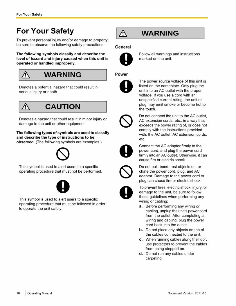
The following symbols classify and describe thelevel of hazard and injury caused when this unit isoperated or handled improperly.
WARNING
Denotes a potential hazard that could result inserious injury or death.
CAUTION
Denotes a hazard that could result in minor injury ordamage to the unit or other equipment.
The following types of symbols are used to classifyand describe the type of instructions to beobserved. (The following symbols are examples.)
This symbol is used to alert users to a specificoperating procedure that must not be performed.
This symbol is used to alert users to a specificoperating procedure that must be followed in orderto operate the unit safely.
WARNING
GeneralFollow all warnings and instructionsmarked on the unit.
PowerThe power source voltage of this unit islisted on the nameplate. Only plug theunit into an AC outlet with the propervoltage. If you use a cord with anunspecified current rating, the unit orplug may emit smoke or become hot tothe touch.
Do not connect the unit to the AC outlet,AC extension cords, etc., in a way thatexceeds the power rating of, or does notcomply with the instructions providedwith, the AC outlet, AC extension cords,etc.
Connect the AC adaptor firmly to thepower cord, and plug the power cordfirmly into an AC outlet. Otherwise, it cancause fire or electric shock.
Do not pull, bend, rest objects on, orchafe the power cord, plug, and ACadaptor. Damage to the power cord orplug can cause fire or electric shock.
To prevent fires, electric shock, injury, ordamage to the unit, be sure to followthese guidelines when performing anywiring or cabling:a. Before performing any wiring or
cabling, unplug the unit’s power cordfrom the outlet. After completing allwiring and cabling, plug the powercord back into the outlet.
b. Do not place any objects on top ofthe cables connected to the unit.
c. When running cables along the floor,use protectors to prevent the cablesfrom being stepped on.
d. Do not run any cables undercarpeting.
10 Operating Manual Document Version 2011-10
For Your Safety
For Your Safety
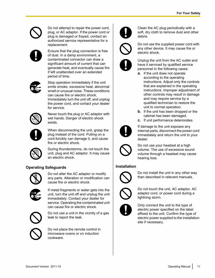
Do not attempt to repair the power cord,plug, or AC adaptor. If the power cord orplug is damaged or frayed, contact anauthorized service representative for areplacement.
Ensure that the plug connection is freeof dust. In a damp environment, acontaminated connector can draw asignificant amount of current that cangenerate heat, and eventually cause fireif left unattended over an extendedperiod of time.
Stop operation immediately if the unitemits smoke, excessive heat, abnormalsmell or unusual noise. These conditionscan cause fire or electric shock.Immediately turn the unit off, and unplugthe power cord, and contact your dealerfor service.
Never touch the plug or AC adaptor withwet hands. Danger of electric shockexists.
When disconnecting the unit, grasp theplug instead of the cord. Pulling on acord forcibly can damage it, and causefire or electric shock.
During thunderstorms, do not touch theunit, plug and AC adaptor. It may causean electric shock.
Operating SafeguardsDo not alter the AC adaptor or modifyany parts. Alteration or modification cancause fire or electric shock.
If metal fragments or water gets into theunit, turn the unit off and unplug the unitimmediately. Contact your dealer forservice. Operating the contaminated unitcan cause fire or electric shock.
Do not use a unit in the vicinity of a gasleak to report the leak.
Do not place the remote control inmicrowave ovens or on inductioncookware.
Clean the AC plug periodically with asoft, dry cloth to remove dust and otherdebris.
Do not use the supplied power cord withany other device. It may cause fire orelectric shock.
Unplug the unit from the AC outlet andhave it serviced by qualified servicepersonnel in the following cases:a. If the unit does not operate
according to the operatinginstructions. Adjust only the controlsthat are explained in the operatinginstructions. Improper adjustment ofother controls may result in damageand may require service by aqualified technician to restore theunit to normal operation.
b. If the unit has been dropped or thecabinet has been damaged.
c. If unit performance deteriorates.
If damage to the unit exposes anyinternal parts, disconnect the power cordimmediately and return the unit to yourdealer.
Do not use your headset at a highvolume. The use of excessive soundvolume through a headset may causehearing loss.
InstallationDo not install the unit in any other waythan described in relevant manuals.
Do not touch the unit, AC adaptor, ACadaptor cord, or power cord during alightning storm.
Only connect the unit to the type ofelectric power specified on the labelaffixed to the unit. Confirm the type ofelectric power supplied to the installationsite if necessary.
Document Version 2011-10 Operating Manual 11
For Your Safety
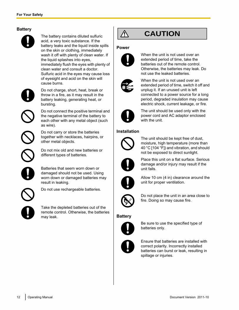
BatteryThe battery contains diluted sulfuricacid, a very toxic substance. If thebattery leaks and the liquid inside spillson the skin or clothing, immediatelywash it off with plenty of clean water. Ifthe liquid splashes into eyes,immediately flush the eyes with plenty ofclean water and consult a doctor.Sulfuric acid in the eyes may cause lossof eyesight and acid on the skin willcause burns.
Do not charge, short, heat, break orthrow in a fire, as it may result in thebattery leaking, generating heat, orbursting.
Do not connect the positive terminal andthe negative terminal of the battery toeach other with any metal object (suchas wire).
Do not carry or store the batteriestogether with necklaces, hairpins, orother metal objects.
Do not mix old and new batteries ordifferent types of batteries.
Batteries that seem worn down ordamaged should not be used. Usingworn down or damaged batteries mayresult in leaking.
Do not use rechargeable batteries.
Take the depleted batteries out of theremote control. Otherwise, the batteriesmay leak.
CAUTION
PowerWhen the unit is not used over anextended period of time, take thebatteries out of the remote control.Otherwise, the batteries may leak. Donot use the leaked batteries.
When the unit is not used over anextended period of time, switch it off andunplug it. If an unused unit is leftconnected to a power source for a longperiod, degraded insulation may causeelectric shock, current leakage, or fire.
The unit should be used only with thepower cord and AC adaptor enclosedwith the unit.
InstallationThe unit should be kept free of dust,moisture, high temperature (more than40 °C [104 °F]) and vibration, and shouldnot be exposed to direct sunlight.
Place this unit on a flat surface. Seriousdamage and/or injury may result if theunit falls.
Allow 10 cm (4 in) clearance around theunit for proper ventilation.
Do not place the unit in an area close tofire. Doing so may cause fire.
BatteryBe sure to use the specified type ofbatteries only.
Ensure that batteries are installed withcorrect polarity. Incorrectly installedbatteries can burst or leak, resulting inspillage or injuries.
12 Operating Manual Document Version 2011-10
For Your Safety
This product contains batteries. Replaceonly with the same or equivalent type.Improper use or replacement may causeoverheating, rupture or explosionresulting in injury or fire. Dispose of usedbatteries according to the instructions ofyour local solid waste officials and localregulations.
When replace the batteries for theremote control, use AA/R6 type dry cell.
Do not install the battery backwards sothat the polarity is reversed.
Document Version 2011-10 Operating Manual 13
For Your Safety
Notes about OperationPlease pay attention to the following points when usingthis device:1. Please contact your dealer for installing,
upgrading, or repairing this device.
2. Do not forcefully hit or shake this device.Dropping or bumping this device can damage orbreak this device.
3. Do not place this device in a freezer or otherlocation where it is exposed to coldtemperatures.Doing so may result in damage or malfunctions.
4. Place this device at least 2 m (6.5 ft) away fromradios, office equipment, microwave ovens, airconditioning units, etc.Noise from electronic devices can cause static andinterference in other devices.
5. Do not place this device in a location where it isexposed to hydrogen sulfide, phosphorous,ammonia, sulfur, carbon, acid, dirt, toxic gas,etc.Doing so may result in damage, and the usablelife-span of the device may decrease.
6. Do not apply insecticides or other volatileliquids to the device, nor leave rubber bands orvinyl objects on the device for extended periodsof time.Doing so may result in alterations to the material orpaint peeling off the device.
7. Do not bring cards with magnetic strips, suchas credit cards and telephone cards, near themicrophone.Cards might become unusable.
8. Do not bring the device near items that emitelectromagnetic waves or that are magnetized(high-frequency sewing machines, electricwelders, magnets, etc.).Doing so may result in static noise or damage.
9. Keep the device at least 10 cm (4 in) away fromall walls.If placed against a wall, the device may not be ableto ventilate properly, which may lead to a systemmalfunction due to overheating.
10. Avoid placing the device in areas with highhumidity, and exposing it to rain.Neither the main unit nor the power plug is waterresistant.
11. The power outlet should be near the productand easily accessible.
About the Operating EnvironmentThis device includes a feature that automatically adjustsvoice transmissions to improve clarity. After beginninga video conference call, adjustments to the callenvironment may not complete immediately, and as aresult voices may cut out or echo. In such cases, at thebeginning of the video conference call, be sure to speakin turn with other parties.
About Moving the DeviceDo not move this device while cords are still connected.Doing so may result in damage to the cords.
Other• This device is a class A information technology
device. Using this device in a residential setting cancause radio wave interference. In these cases, theuser may be responsible for taking appropriatemeasures to prevent the interference.
• The unit may not operate in the event of a powerfailure.
• The illustrations and screenshots in this manual arefor reference only and may vary from the actualproduct.
14 Operating Manual Document Version 2011-10
Before Operation
Before Operation
Data SecurityWe recommend observing the security precautionsdescribed in this section, in order to prevent thedisclosure of sensitive information.Panasonic is not responsible for any damagescaused by improper use of this device.
Preventing Data LossKeep a separate record of the encryption key and allinformation stored in the contact list.
Preventing Data Disclosure• Do not place this device in a location that can be
accessed or removed without authorization.• If important information is saved on this device,
store it in an appropriate location.• Do not store sensitive personal information in the
unit.• In the following situations, make a record of the
encryption key and the information stored in thecontact list and return the unit to the state it was inwhen purchased (Page 106).– Before lending or disposing of the unit– Before handing the unit over to a third party– Before having the unit serviced
• Make sure the unit is serviced by only a certifiedtechnician.
This device can register and store personal data (thecontact list, encryption key, connection history, etc.). Inorder to prevent the disclosure of data stored on thisdevice, make sure to delete all data that is registeredand stored on this device prior to disposing of, lending,or returning this device (Page 106).
Preventing Data Disclosure over theNetwork• To ensure the security of private conversations,
only connect the unit to a secure network.• To prevent unauthorized access, only connect the
unit to a network that is properly managed.• Make sure all computers connected to the unit
employ up-to-date security measures.• To prevent illegal access from the Internet, activate
a Firewall.
Privacy and Right ofPublicityBy installing and using this device, you are responsiblefor maintaining the privacy and usage rights of imagesand other data (including sound picked up by themicrophone). Use this device accordingly.
• Privacy is generally said to be, "A legal guaranteeand right not to have the details of one’s personallife unreasonably publicized, and the right to be ableto control information about oneself. In addition,right of publicity is a right not to have a likeness ofone’s face or figure photographed and publicizedwithout consent".
• When the Automatic Answer feature is enabled,transmission begins as soon as a video conferencecall is received. The receiver of the videoconference call will begin transmitting as soon asthe video conference call is received at any time,from any caller. Please be aware when theAutomatic Answer feature is enabled, there is a riskthat due to an unexpected, automatically answeredvideo conference call, privacy rights may beviolated or sensitive information may be transmittedto unauthorized parties.
Document Version 2011-10 Operating Manual 15
Before Operation
Federal Communications CommissionRequirements
Federal Communications Commission Interference StatementThis equipment has been tested and found to comply with the limits for a Class A digital device, pursuant toPart 15 of the FCC Rules. These limits are designed to provide reasonable protection against harmfulinterference when the equipment is operated in a commercial environment. This equipment generates, usesand can radiate radio frequency energy and, if not installed and used in accordance with the instructionsmanual, may cause harmful interference to radio communications. Operation of this equipment in a residentialarea is likely to cause harmful interference in which case the user will be required to correct the interferenceat his own expense.
FCC CautionTo assure continued compliance, (example - use only shielded interface cables when connectingto other devices). Any changes or modifications not expressly approved by the party responsiblefor compliance could void the user’s authority to operate this equipment.
16 Operating Manual Document Version 2011-10
Before Operation
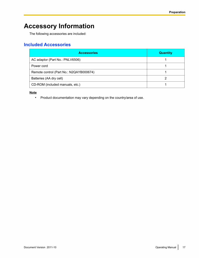
Accessory InformationThe following accessories are included:
Included AccessoriesAccessories Quantity
AC adaptor (Part No.: PNLV6506) 1
Power cord 1
Remote control (Part No.: N2QAYB000674) 1
Batteries (AA dry cell) 2
CD-ROM (included manuals, etc.) 1
Note• Product documentation may vary depending on the country/area of use.
Document Version 2011-10 Operating Manual 17
Preparation
Preparation
Part Names and Usage
Main Unit (Front)
A B
D E
C
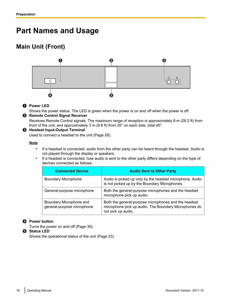
Power LEDShows the power status. The LED is green when the power is on and off when the power is off.Remote Control Signal ReceiverReceives Remote Control signals. The maximum range of reception is approximately 8 m (26.2 ft) fromfront of the unit, and approximately 3 m (9.8 ft) from 20° on each side, total 40°.Headset Input-Output TerminalUsed to connect a headset to the unit (Page 28).
Note• If a headset is connected, audio from the other party can be heard through the headset. Audio is
not played through the display or speakers.• If a headset is connected, how audio is sent to the other party differs depending on the type of
devices connected as follows:
Connected Device Audio Sent to Other Party
Boundary Microphone Audio is picked up only by the headset microphone. Audiois not picked up by the Boundary Microphones.
General-purpose microphone Both the general-purpose microphones and the headsetmicrophone pick up audio.
Boundary Microphone andgeneral-purpose microphone
Both the general-purpose microphones and the headsetmicrophone pick up audio. The Boundary Microphones donot pick up audio.
Power buttonTurns the power on and off (Page 30).Status LEDShows the operational status of the unit (Page 23).
18 Operating Manual Document Version 2011-10
Preparation
Main Unit (Back)KX-VC600
A B C F GE
H I J OK L M N
D
KX-VC300
B D F GE
H I J OK L M N
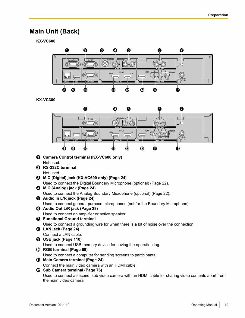
Camera Control terminal (KX-VC600 only)Not used.RS-232C terminalNot used.MIC (Digital) jack (KX-VC600 only) (Page 24)Used to connect the Digital Boundary Microphone (optional) (Page 22).MIC (Analog) jack (Page 24)Used to connect the Analog Boundary Microphone (optional) (Page 22).Audio In L/R jack (Page 24)Used to connect general-purpose microphones (not for the Boundary Microphone).Audio Out L/R jack (Page 28)Used to connect an amplifier or active speaker.Functional Ground terminalUsed to connect a grounding wire for when there is a lot of noise over the connection.LAN jack (Page 24)Connect a LAN cable.USB jack (Page 110)Used to connect USB memory device for saving the operation log.RGB terminal (Page 69)Used to connect a computer for sending screens to participants.Main Camera terminal (Page 24)Connect the main video camera with an HDMI cable.Sub Camera terminal (Page 76)Used to connect a second, sub video camera with an HDMI cable for sharing video contents apart fromthe main video camera.
Document Version 2011-10 Operating Manual 19
Preparation
HDMI terminal (Page 24)Used to connect to the display with an HDMI cable.Component terminal (Page 29)Used to connect to the display with a component video cable.DC IN (Page 25)Connect the AC adaptor’s DC cord.
20 Operating Manual Document Version 2011-10
Preparation
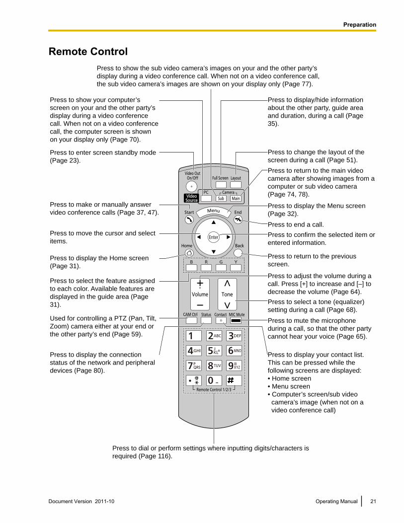
Remote ControlPress to show the sub video camera’s images on your and the other party’s
display during a video conference call. When not on a video conference call,
the sub video camera’s images are shown on your display only (Page 77).
Press to display/hide information
about the other party, guide area
and duration, during a call (Page
35).
Press to change the layout of the
screen during a call (Page 51).
Press to return to the main video
camera after showing images from a
computer or sub video camera
(Page 74, 78).
Press to display the Menu screen
(Page 32).
Press to end a call.
Press to confirm the selected item or
entered information.
Press to return to the previous
screen.
Press to adjust the volume during a
call. Press [+] to increase and [–] to
decrease the volume (Page 64).
Press to select a tone (equalizer)
setting during a call (Page 68).
Press to mute the microphone
during a call, so that the other party
cannot hear your voice (Page 65).
Press to display your contact list.
This can be pressed while the
following screens are displayed:
• Home screen
• Menu screen
• Computer’s screen/sub video
camera’s image (when not on a
video conference call)
Press to show your computer’s
screen on your and the other party’s
display during a video conference
call. When not on a video conference
call, the computer screen is shown
on your display only (Page 70).
Press to enter screen standby mode
(Page 23).
Press to make or manually answer
video conference calls (Page 37, 47).
Press to move the cursor and select
items.
Press to display the Home screen
(Page 31).
Used for controlling a PTZ (Pan, Tilt,
Zoom) camera either at your end or
the other party’s end (Page 59).
Press to select the feature assigned
to each color. Available features are
displayed in the guide area (Page
31).
Press to display the connection
status of the network and peripheral
devices (Page 80).
Press to dial or perform settings where inputting digits/characters is
required (Page 116).
Document Version 2011-10 Operating Manual 21
Preparation

Boundary Microphone (Optional Accessory)Boundary Microphone(Digital Interface Type)
(Proprietary cable included.Cable length: approx. 8.5 m
[approx. 28 ft])
Boundary Microphone(Analog Interface Type)
(Proprietary cable included.Cable length: approx. 7 m
[approx. 23 ft])
A B A B
Model No.: KX-VCA001 Model No.: KX-VCA002
MIC Mute buttonPress to mute your own voice so that other video conference call participants cannot hear you(Page 65).LEDIndicate the operational status of the Boundary Microphone.Red (on): Microphone is muted.Green (on): TransmittingOrange (blinking in 1 second intervals): Starting upOff: No transmission in progress or microphone disabled because headset is connected, etc.
Note• Up to 4 Digital Boundary Microphones can be connected in cascade.• Analog Boundary Microphones cannot be connected in cascade.• Contact your dealer for purchase information.
Federal Communications Commission RequirementsFederal Communications Commission Interference StatementThis equipment has been tested and found to comply with the limits for a Class A digital device, pursuant toPart 15 of the FCC Rules. These limits are designed to provide reasonable protection against harmfulinterference when the equipment is operated in a commercial environment. This equipment generates, usesand can radiate radio frequency energy and, if not installed and used in accordance with the instructionsmanual, may cause harmful interference to radio communications. Operation of this equipment in a residentialarea is likely to cause harmful interference in which case the user will be required to correct the interferenceat his own expense.
FCC CautionTo assure continued compliance, (example - use only shielded interface cables when connectingto other devices). Any changes or modifications not expressly approved by the party responsiblefor compliance could void the user’s authority to operate this equipment.
This device complies with Part 15 of the FCC Rules. Operation is subject to the following two conditions: (1)This device may not cause harmful interference, and (2) this device must accept any interference received,including interference that may cause undesired operation.
For Canada UsersThis Class A digital apparatus complies with Canadian ICES-003.Cet appareil numérique de la classe A est conforme à la norme NMB-003 du Canada.
22 Operating Manual Document Version 2011-10
Preparation
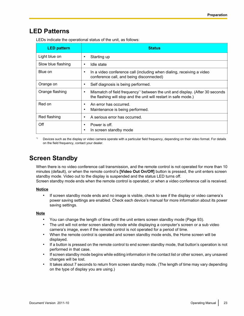
LED PatternsLEDs indicate the operational status of the unit, as follows:
LED pattern Status
Light blue on • Starting up
Slow blue flashing • Idle state
Blue on • In a video conference call (including when dialing, receiving a videoconference call, and being disconnected)
Orange on • Self diagnosis is being performed.
Orange flashing • Mismatch of field frequency*1 between the unit and display. (After 30 secondsthe flashing will stop and the unit will restart in safe mode.)
Red on • An error has occurred.• Maintenance is being performed.
Red flashing • A serious error has occurred.
Off • Power is off.• In screen standby mode
*1 Devices such as the display or video camera operate with a particular field frequency, depending on their video format. For detailson the field frequency, contact your dealer.
Screen StandbyWhen there is no video conference call transmission, and the remote control is not operated for more than 10minutes (default), or when the remote control’s [Video Out On/Off] button is pressed, the unit enters screenstandby mode. Video out to the display is suspended and the status LED turns off.Screen standby mode ends when the remote control is operated, or when a video conference call is received.
Notice• If screen standby mode ends and no image is visible, check to see if the display or video camera’s
power saving settings are enabled. Check each device’s manual for more information about its powersaving settings.
Note• You can change the length of time until the unit enters screen standby mode (Page 93).• The unit will not enter screen standby mode while displaying a computer’s screen or a sub video
camera’s image, even if the remote control is not operated for a period of time.• When the remote control is operated and screen standby mode ends, the Home screen will be
displayed.• If a button is pressed on the remote control to end screen standby mode, that button’s operation is not
performed in that case.• If screen standby mode begins while editing information in the contact list or other screen, any unsaved
changes will be lost.• It takes about 7 seconds to return from screen standby mode. (The length of time may vary depending
on the type of display you are using.)
Document Version 2011-10 Operating Manual 23
Preparation
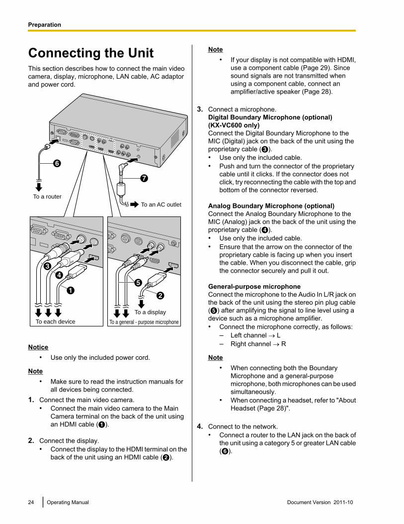
Connecting the UnitThis section describes how to connect the main videocamera, display, microphone, LAN cable, AC adaptorand power cord.
G
F
To each device
To a router
To a display
To a general - purpose microphone
To an AC outlet
A
DC
B
E
Notice• Use only the included power cord.
Note• Make sure to read the instruction manuals for
all devices being connected.1. Connect the main video camera.
• Connect the main video camera to the MainCamera terminal on the back of the unit usingan HDMI cable (A).
2. Connect the display.• Connect the display to the HDMI terminal on the
back of the unit using an HDMI cable (B).
Note• If your display is not compatible with HDMI,
use a component cable (Page 29). Sincesound signals are not transmitted whenusing a component cable, connect anamplifier/active speaker (Page 28).
3. Connect a microphone.Digital Boundary Microphone (optional)(KX-VC600 only)Connect the Digital Boundary Microphone to theMIC (Digital) jack on the back of the unit using theproprietary cable (C).• Use only the included cable.• Push and turn the connector of the proprietary
cable until it clicks. If the connector does notclick, try reconnecting the cable with the top andbottom of the connector reversed.
Analog Boundary Microphone (optional)Connect the Analog Boundary Microphone to theMIC (Analog) jack on the back of the unit using theproprietary cable (D).• Use only the included cable.• Ensure that the arrow on the connector of the
proprietary cable is facing up when you insertthe cable. When you disconnect the cable, gripthe connector securely and pull it out.
General-purpose microphoneConnect the microphone to the Audio In L/R jack onthe back of the unit using the stereo pin plug cable(E) after amplifying the signal to line level using adevice such as a microphone amplifier.• Connect the microphone correctly, as follows:
– Left channel ® L– Right channel ® R
Note• When connecting both the Boundary
Microphone and a general-purposemicrophone, both microphones can be usedsimultaneously.
• When connecting a headset, refer to "AboutHeadset (Page 28)".
4. Connect to the network.• Connect a router to the LAN jack on the back of
the unit using a category 5 or greater LAN cable(F).
24 Operating Manual Document Version 2011-10
Preparation
Note• Set the hub/router to Auto Negotiation
mode.• If the system is set to 100M Full Duplex, it
is necessary to change the system setting.For details, contact your dealer.
• Do not connect to a hub/router set to HalfDuplex.
• For more details about routers and DCEs,refer to the documentation for each device.
5. Connect the power cord to the AC adaptor.• Use only the power cord included with the unit.
6. Insert the AC adaptor’s DC cord (G) into the DC INterminal on the back of the unit.• Use only the AC adaptor included with the unit.
7. Plug in the power cord into the power outlet.• Choose an outlet that is convenient for
plugging/unplugging.
System Layout ExamplesDisplay and Main Video CameraPlace the display and main video camera at the sameside of the room.
Note• If you use speakers, refer to "Amplifier/Active
Speaker Connection" (Page 28).
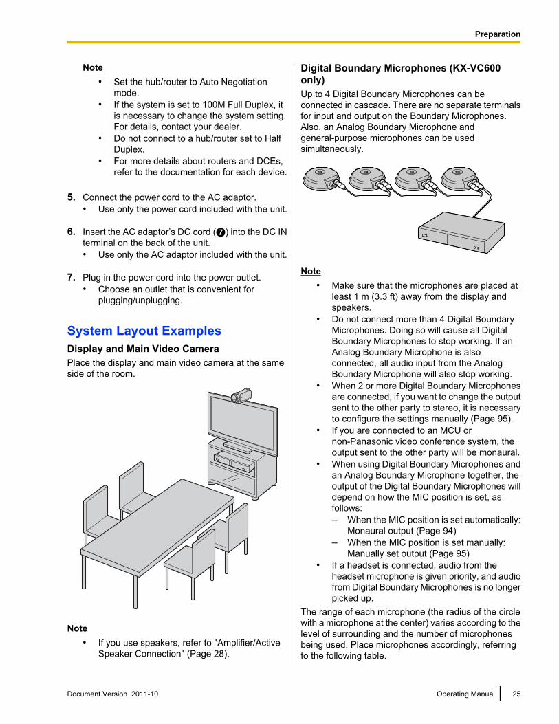
Digital Boundary Microphones (KX-VC600only)Up to 4 Digital Boundary Microphones can beconnected in cascade. There are no separate terminalsfor input and output on the Boundary Microphones.Also, an Analog Boundary Microphone andgeneral-purpose microphones can be usedsimultaneously.
Note• Make sure that the microphones are placed at
least 1 m (3.3 ft) away from the display andspeakers.
• Do not connect more than 4 Digital BoundaryMicrophones. Doing so will cause all DigitalBoundary Microphones to stop working. If anAnalog Boundary Microphone is alsoconnected, all audio input from the AnalogBoundary Microphone will also stop working.
• When 2 or more Digital Boundary Microphonesare connected, if you want to change the outputsent to the other party to stereo, it is necessaryto configure the settings manually (Page 95).
• If you are connected to an MCU ornon-Panasonic video conference system, theoutput sent to the other party will be monaural.
• When using Digital Boundary Microphones andan Analog Boundary Microphone together, theoutput of the Digital Boundary Microphones willdepend on how the MIC position is set, asfollows:– When the MIC position is set automatically:
Monaural output (Page 94)– When the MIC position is set manually:
Manually set output (Page 95)• If a headset is connected, audio from the
headset microphone is given priority, and audiofrom Digital Boundary Microphones is no longerpicked up.
The range of each microphone (the radius of the circlewith a microphone at the center) varies according to thelevel of surrounding and the number of microphonesbeing used. Place microphones accordingly, referringto the following table.
Document Version 2011-10 Operating Manual 25
Preparation
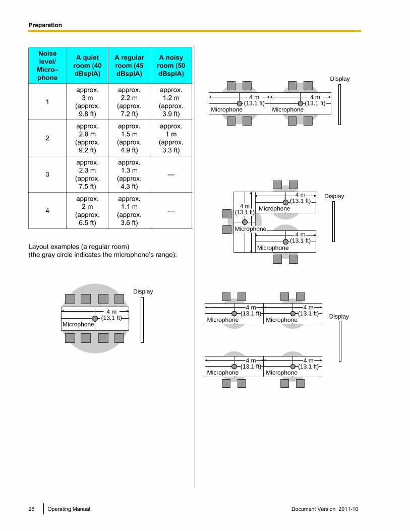
Noiselevel/
Micro–phone
A quietroom (40dBsplA)
A regularroom (45dBsplA)
A noisyroom (50dBsplA)
1
approx.3 m
(approx.9.8 ft)
approx.2.2 m
(approx.7.2 ft)
approx.1.2 m
(approx.3.9 ft)
2
approx.2.8 m
(approx.9.2 ft)
approx.1.5 m
(approx.4.9 ft)
approx.1 m
(approx.3.3 ft)
3
approx.2.3 m
(approx.7.5 ft)
approx.1.3 m
(approx.4.3 ft)
—
4
approx.2 m
(approx.6.5 ft)
approx.1.1 m
(approx.3.6 ft)
—
Layout examples (a regular room)(the gray circle indicates the microphone’s range):
Display
Microphone
4 m(13.1 ft)
4 m(13.1 ft)
Microphone
Display
4 m(13.1 ft)
Microphone
Microphone
Microphone
Microphone
4 m(13.1 ft)
4 m(13.1 ft)
4 m(13.1 ft)
Display
Microphone Microphone
Microphone Microphone
4 m(13.1 ft)
4 m(13.1 ft)
4 m(13.1 ft)
4 m(13.1 ft)
Display
26 Operating Manual Document Version 2011-10
Preparation
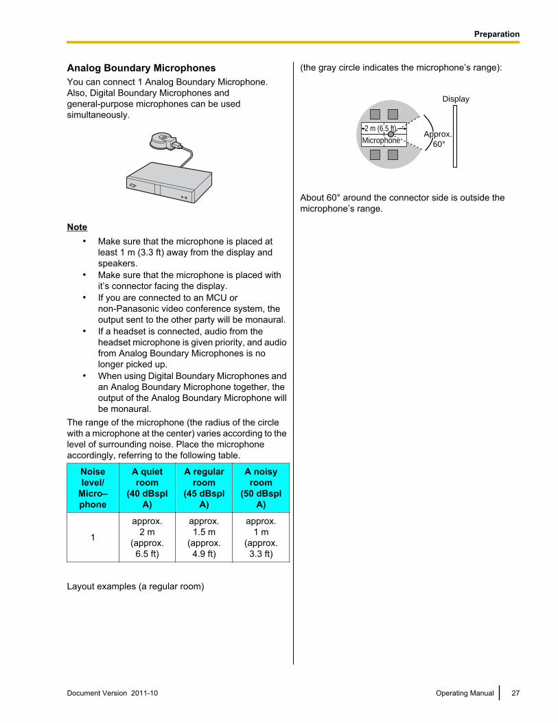
Analog Boundary MicrophonesYou can connect 1 Analog Boundary Microphone.Also, Digital Boundary Microphones andgeneral-purpose microphones can be usedsimultaneously.
Note• Make sure that the microphone is placed at
least 1 m (3.3 ft) away from the display andspeakers.
• Make sure that the microphone is placed withit’s connector facing the display.
• If you are connected to an MCU ornon-Panasonic video conference system, theoutput sent to the other party will be monaural.
• If a headset is connected, audio from theheadset microphone is given priority, and audiofrom Analog Boundary Microphones is nolonger picked up.
• When using Digital Boundary Microphones andan Analog Boundary Microphone together, theoutput of the Analog Boundary Microphone willbe monaural.
The range of the microphone (the radius of the circlewith a microphone at the center) varies according to thelevel of surrounding noise. Place the microphoneaccordingly, referring to the following table.
Noiselevel/
Micro–phone
A quietroom
(40 dBsplA)
A regularroom
(45 dBsplA)
A noisyroom
(50 dBsplA)
1
approx.2 m
(approx.6.5 ft)
approx.1.5 m
(approx.4.9 ft)
approx.1 m
(approx.3.3 ft)
Layout examples (a regular room)
(the gray circle indicates the microphone’s range):
Display
MicrophoneMicrophoneMicrophoneApprox. Approx.
6060°
Approx.
60°
2 m (6.5 ft)
About 60° around the connector side is outside themicrophone’s range.
Document Version 2011-10 Operating Manual 27
Preparation
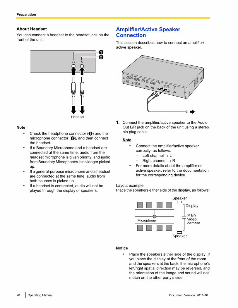
About HeadsetYou can connect a headset to the headset jack on thefront of the unit.
AB
Headset
Note• Check the headphone connector (A) and the
microphone connector (B), and then connectthe headset.
• If a Boundary Microphone and a headset areconnected at the same time, audio from theheadset microphone is given priority, and audiofrom Boundary Microphones is no longer pickedup.
• If a general-purpose microphone and a headsetare connected at the same time, audio fromboth sources is picked up.
• If a headset is connected, audio will not beplayed through the display or speakers.
Amplifier/Active SpeakerConnectionThis section describes how to connect an amplifier/active speaker.
1. Connect the amplifier/active speaker to the AudioOut L/R jack on the back of the unit using a stereopin plug cable.
Note• Connect the amplifier/active speaker
correctly, as follows:– Left channel ® L– Right channel ® R
• For more details about the amplifier oractive speaker, refer to the documentationfor the corresponding device.
Layout example:Place the speakers either side of the display, as follows:
Microphone
Main video camera
Display
Speaker
Speaker
Notice• Place the speakers either side of the display. If
you place the display at the front of the roomand the speakers at the back, the microphone’sleft/right spatial direction may be reversed, andthe orientation of the image and sound will notmatch on the other party’s side.
28 Operating Manual Document Version 2011-10
Preparation
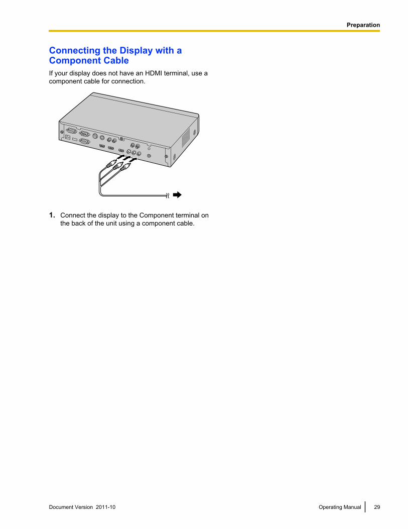
Connecting the Display with aComponent CableIf your display does not have an HDMI terminal, use acomponent cable for connection.
1. Connect the display to the Component terminal onthe back of the unit using a component cable.
Document Version 2011-10 Operating Manual 29
Preparation
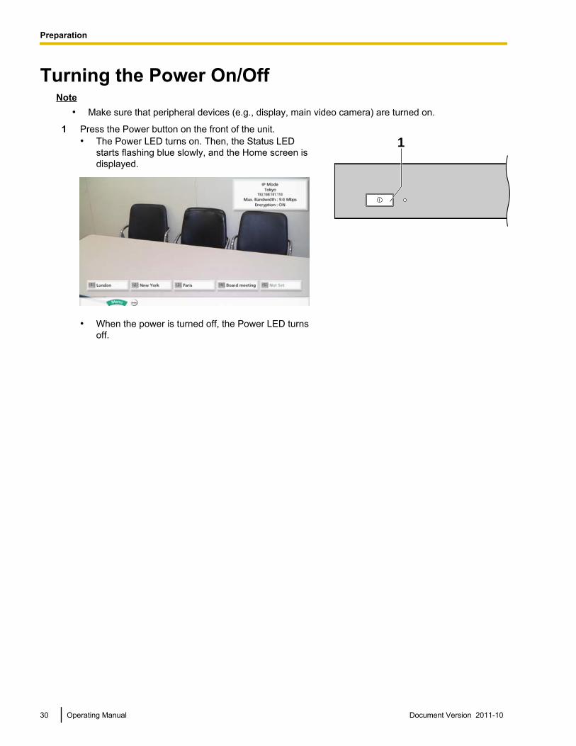
Turning the Power On/OffNote
• Make sure that peripheral devices (e.g., display, main video camera) are turned on.
1 Press the Power button on the front of the unit.• The Power LED turns on. Then, the Status LED
starts flashing blue slowly, and the Home screen isdisplayed.
• When the power is turned off, the Power LED turnsoff.
1
30 Operating Manual Document Version 2011-10
Preparation
Screen Display
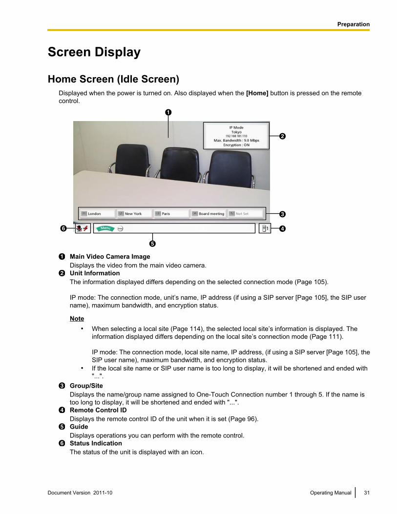
Home Screen (Idle Screen)Displayed when the power is turned on. Also displayed when the [Home] button is pressed on the remotecontrol.
A
B
C
DF
E
Main Video Camera ImageDisplays the video from the main video camera.Unit InformationThe information displayed differs depending on the selected connection mode (Page 105).
IP mode: The connection mode, unit’s name, IP address (if using a SIP server [Page 105], the SIP username), maximum bandwidth, and encryption status.
Note• When selecting a local site (Page 114), the selected local site’s information is displayed. The
information displayed differs depending on the local site’s connection mode (Page 111).
IP mode: The connection mode, local site name, IP address, (if using a SIP server [Page 105], theSIP user name), maximum bandwidth, and encryption status.
• If the local site name or SIP user name is too long to display, it will be shortened and ended with"...".
Group/SiteDisplays the name/group name assigned to One-Touch Connection number 1 through 5. If the name istoo long to display, it will be shortened and ended with "...".Remote Control IDDisplays the remote control ID of the unit when it is set (Page 96).GuideDisplays operations you can perform with the remote control.Status IndicationThe status of the unit is displayed with an icon.
Document Version 2011-10 Operating Manual 31
Preparation
Icon Status
Microphone is muted.
Note• If the MIC detection setting has been disabled through system settings
(Page 92), the icon will not be displayed even if the Boundary Microphone orheadset microphone is muted.
Network, server (any kind), or peripheral connection error (no connection, device error,etc.).
Note• If the MIC detection setting has been disabled through system settings
(Page 92), the icon will not be displayed even if the Boundary Microphone orheadset is disconnected. However, if there are no connections, or there is a deviceerror in other devices such as the LAN cable, the icon will be displayed.
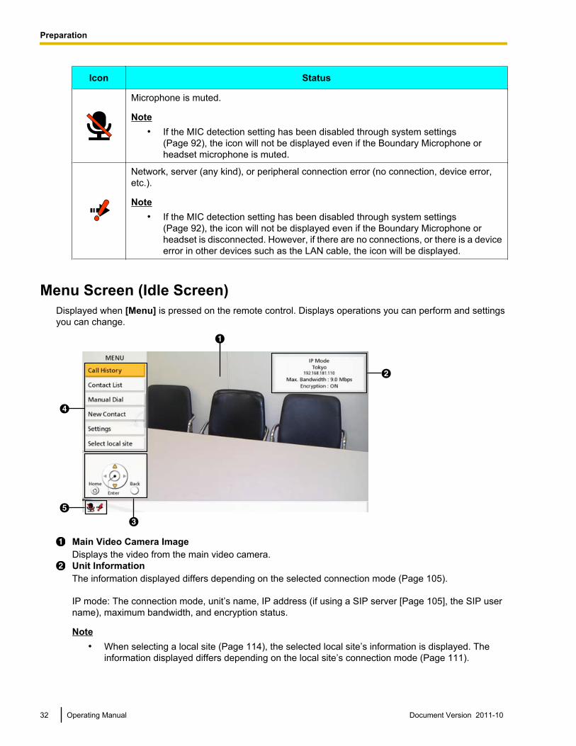
Menu Screen (Idle Screen)Displayed when [Menu] is pressed on the remote control. Displays operations you can perform and settingsyou can change.
D
B
A
E
C
Main Video Camera ImageDisplays the video from the main video camera.Unit InformationThe information displayed differs depending on the selected connection mode (Page 105).
IP mode: The connection mode, unit’s name, IP address (if using a SIP server [Page 105], the SIP username), maximum bandwidth, and encryption status.
Note• When selecting a local site (Page 114), the selected local site’s information is displayed. The
information displayed differs depending on the local site’s connection mode (Page 111).
32 Operating Manual Document Version 2011-10
Preparation
IP mode: The connection mode, local site name, IP address, (if using a SIP server [Page 105], theSIP user name), maximum bandwidth, and encryption status.
• If the local site name or SIP user name is too long to display, it will be shortened and ended with"...".
GuideDisplays operations you can perform with the remote control when performing features or changingsettings.Menu ListDisplays the various functions you can use and settings available to change.Status IndicationThe status of the unit is displayed with an icon (Page 31).
Document Version 2011-10 Operating Manual 33
Preparation
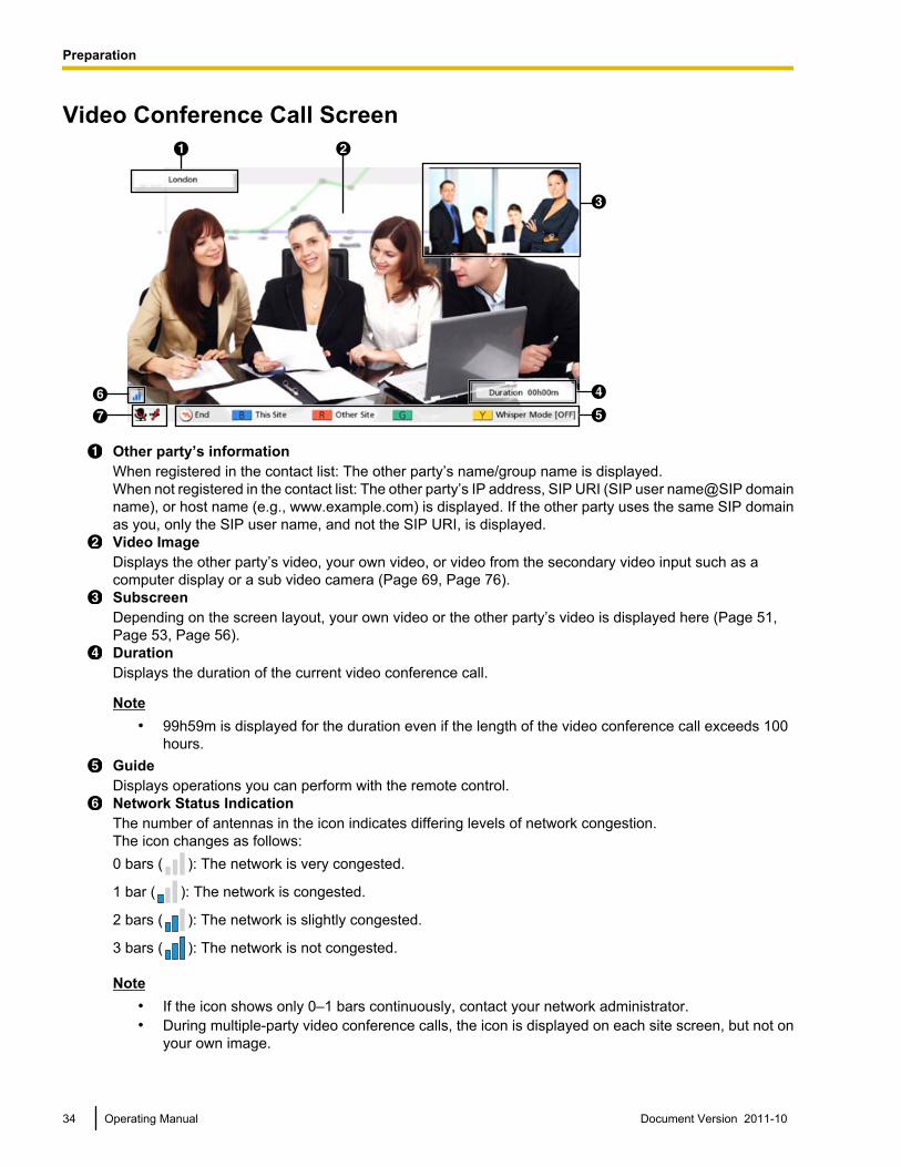
Video Conference Call ScreenA
DF
B
C
EG
Other party’s informationWhen registered in the contact list: The other party’s name/group name is displayed.When not registered in the contact list: The other party’s IP address, SIP URI (SIP user name@SIP domainname), or host name (e.g., www.example.com) is displayed. If the other party uses the same SIP domainas you, only the SIP user name, and not the SIP URI, is displayed.Video ImageDisplays the other party’s video, your own video, or video from the secondary video input such as acomputer display or a sub video camera (Page 69, Page 76).SubscreenDepending on the screen layout, your own video or the other party’s video is displayed here (Page 51,Page 53, Page 56).DurationDisplays the duration of the current video conference call.
Note• 99h59m is displayed for the duration even if the length of the video conference call exceeds 100
hours.GuideDisplays operations you can perform with the remote control.Network Status IndicationThe number of antennas in the icon indicates differing levels of network congestion.The icon changes as follows:0 bars ( ): The network is very congested.
1 bar ( ): The network is congested.
2 bars ( ): The network is slightly congested.
3 bars ( ): The network is not congested.
Note• If the icon shows only 0–1 bars continuously, contact your network administrator.• During multiple-party video conference calls, the icon is displayed on each site screen, but not on
your own image.
34 Operating Manual Document Version 2011-10
Preparation
• You can set whether to display the icon. This setting affects all displayed images (excluding yourown image) (Page 92). For example, if icon display has been enabled, the icon will be displayedon the image of all other parties, but not on your own image. However, if icon display has beendisabled, the icon will not be displayed on any of the images. Regardless of icon display settings,the icon is not displayed while the combined computer/video feed screen is being displayed(Page 70).
Status IndicationThe status of the unit is displayed with an icon (Page 31).
Note• Pressing [Full Screen] on the remote control will hide or unhide the other party’s information, duration,
network status indication*1, and guide displays.*1 If the network status indication has been set to not be displayed, pressing [Full Screen] will not show the icon.
Document Version 2011-10 Operating Manual 35
Preparation
Making a Video Conference CallYou can make a video conference call using one of the following methods.
Note• During a video conference call, you cannot perform the following operations:
– Pressing [Menu] to display the Menu screen.– Pressing [Contact] to display the contact list screen.
• Make sure that peripheral devices (e.g., display, main video camera) are turned on.• If a called party does not answer a video conference call within approximately 60 seconds, the call will
be terminated automatically.• If you are using the KX-VC300, 3-party/4-party video conference calls can only be made after
purchasing an activation key card (KX-VCS301) to activate multiple-party video conference calls(Page 107). For details about the activation key, contact your dealer.
• 2-party/3-party/4-party video conference calls can be made using the outgoing call history.• Only 2-party video conference calls can be made using the incoming call history.• You cannot add parties to an existing video conference call.• During a 3-party/4-party video conference call, even if only one party ends the video conference call,
the rest of the parties will also be disconnected.• A video conference call will start with only the parties that answered the call. For example, if only one
party answers a 4-party video conference call, the video conference call will start as a 2-party videoconference call.
• 3-party/4-party video conference calls may not be possible depending on bandwidth settings(Page 90, Page 112).
• Video conference calls can be made using a SIP URI through a SIP server only when in IP Mode andif SIP settings have been made correctly.
• When connecting to non-Panasonic video conference systems, you can make only 2-party videoconference calls.
Calling Using Speed Dial (2-party Conference/3-party Conference/4-party Conference)
Note• To call using speed dial, you need to have a speed dial number programmed in "Speed Dial" in the
contact list (Page 84).
36 Operating Manual Document Version 2011-10
S
t
a
r
t
i
n
g
a
V
i
d
e
o
C
o
n
f
e
r
e
n
c
e
Starting a Video Conference
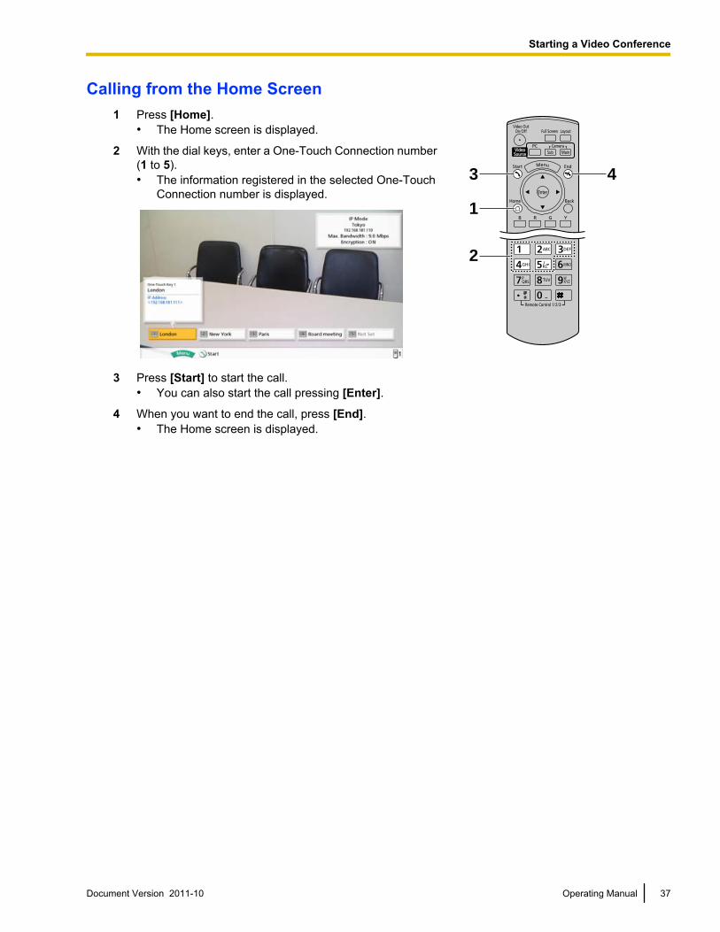
Calling from the Home Screen1 Press [Home].
• The Home screen is displayed.
3
2
1
4
2 With the dial keys, enter a One-Touch Connection number(1 to 5).• The information registered in the selected One-Touch
Connection number is displayed.
3 Press [Start] to start the call.• You can also start the call pressing [Enter].
4 When you want to end the call, press [End].• The Home screen is displayed.
Document Version 2011-10 Operating Manual 37
Starting a Video Conference
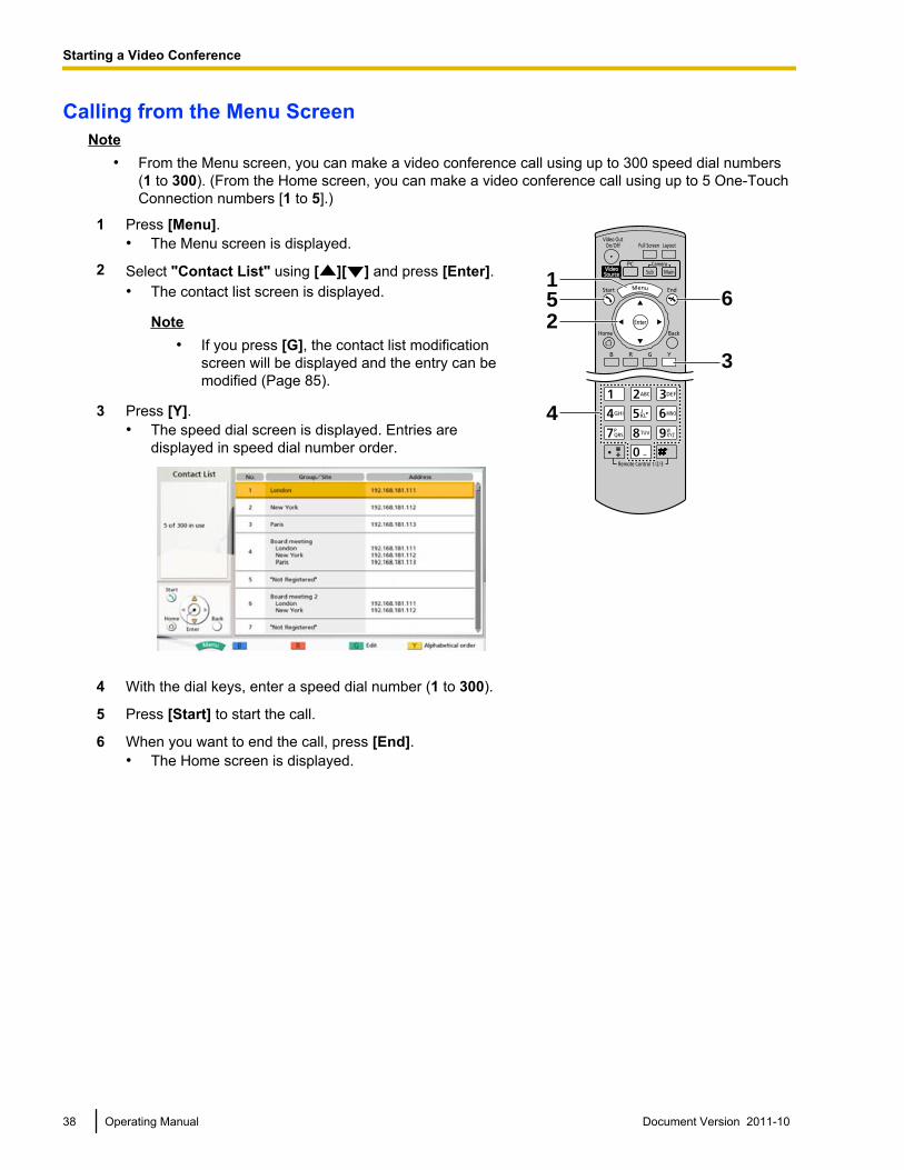
Calling from the Menu ScreenNote
• From the Menu screen, you can make a video conference call using up to 300 speed dial numbers(1 to 300). (From the Home screen, you can make a video conference call using up to 5 One-TouchConnection numbers [1 to 5].)
1 Press [Menu].• The Menu screen is displayed.
4
5
3
2
16
2 Select "Contact List" using [ ][ ] and press [Enter].• The contact list screen is displayed.
Note• If you press [G], the contact list modification
screen will be displayed and the entry can bemodified (Page 85).
3 Press [Y].• The speed dial screen is displayed. Entries are
displayed in speed dial number order.
4 With the dial keys, enter a speed dial number (1 to 300).
5 Press [Start] to start the call.
6 When you want to end the call, press [End].• The Home screen is displayed.
38 Operating Manual Document Version 2011-10
Starting a Video Conference
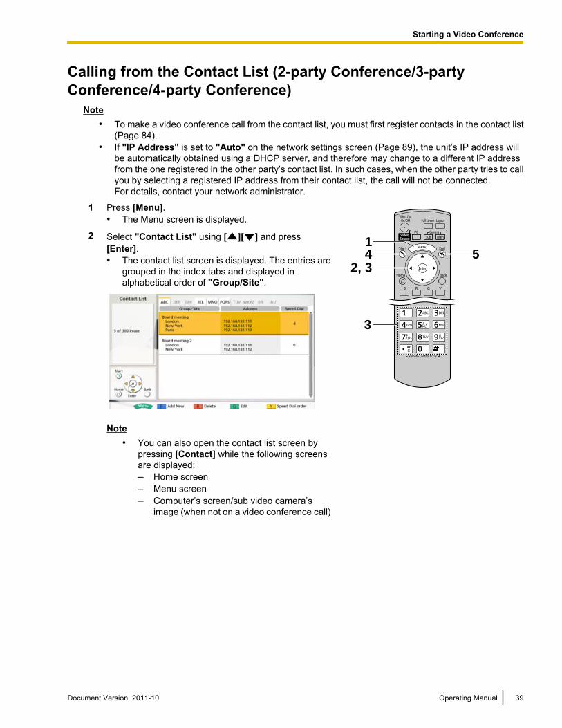
Calling from the Contact List (2-party Conference/3-partyConference/4-party Conference)
Note• To make a video conference call from the contact list, you must first register contacts in the contact list
(Page 84).• If "IP Address" is set to "Auto" on the network settings screen (Page 89), the unit’s IP address will
be automatically obtained using a DHCP server, and therefore may change to a different IP addressfrom the one registered in the other party’s contact list. In such cases, when the other party tries to callyou by selecting a registered IP address from their contact list, the call will not be connected. For details, contact your network administrator.
1 Press [Menu].• The Menu screen is displayed.
3
4 52, 3
12 Select "Contact List" using [ ][ ] and press
[Enter].• The contact list screen is displayed. The entries are
grouped in the index tabs and displayed inalphabetical order of "Group/Site".
Note• You can also open the contact list screen by
pressing [Contact] while the following screensare displayed:– Home screen– Menu screen– Computer’s screen/sub video camera’s
image (when not on a video conference call)
Document Version 2011-10 Operating Manual 39
Starting a Video Conference
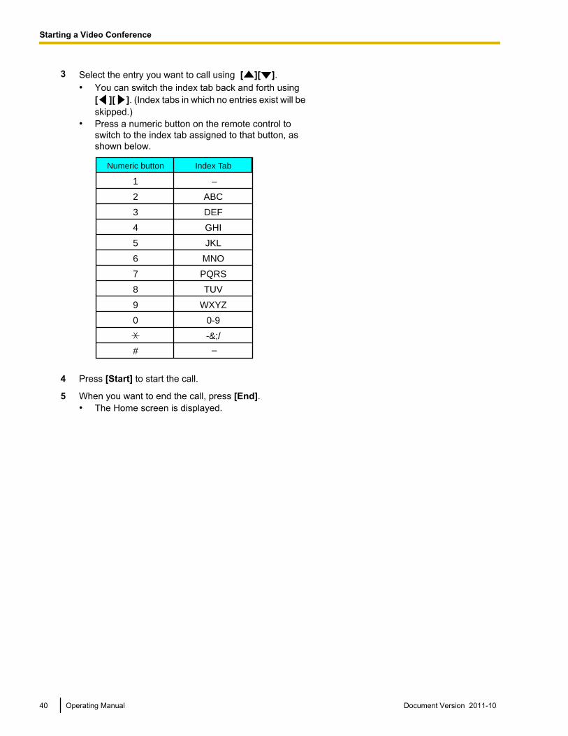
3 Select the entry you want to call using [ ][ ].• You can switch the index tab back and forth using
[ ][ ]. (Index tabs in which no entries exist will beskipped.)
• Press a numeric button on the remote control toswitch to the index tab assigned to that button, asshown below.
Numeric button
1
2
3
4
5
6
7
8
9
0
#
Index Tab
–
ABC
DEF
GHI
JKL
MNO
PQRS
TUV
WXYZ
0-9
-&;/
–
4 Press [Start] to start the call.
5 When you want to end the call, press [End].• The Home screen is displayed.
40 Operating Manual Document Version 2011-10
Starting a Video Conference
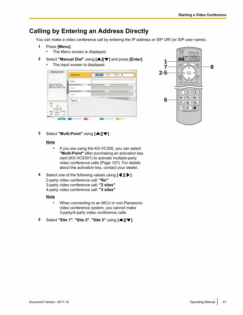
Calling by Entering an Address DirectlyYou can make a video conference call by entering the IP address or SIP URI (or SIP user name).
1 Press [Menu].• The Menu screen is displayed.
7 81
6
2-5
2 Select "Manual Dial" using [ ][ ] and press [Enter].• The input screen is displayed.
3 Select "Multi-Point" using [ ][ ].
Note• If you are using the KX-VC300, you can select
"Multi-Point" after purchasing an activation keycard (KX-VCS301) to activate multiple-partyvideo conference calls (Page 107). For detailsabout the activation key, contact your dealer.
4 Select one of the following values using [ ][ ].2-party video conference call: "No"3-party video conference call: "2 sites"4-party video conference call: "3 sites"
Note• When connecting to an MCU or non-Panasonic
video conference system, you cannot make3-party/4-party video conference calls.
5 Select "Site 1", "Site 2", "Site 3" using [ ][ ].
Document Version 2011-10 Operating Manual 41
Starting a Video Conference
6 Enter the IP address or SIP URI (or SIP user name).
Note• If the IP address contains 1 or 2 digit numbers,
enter these numbers as they are. Do not enterlike [.001].Example: The IP address is [192.168.0.1].– Correct entry: [192.168.0.1]– Wrong entry: [192.168.000.001]
• To initiate a video conference call by entering aSIP URI (SIP user name@SIP domain name),you must set "SIP Server" to "ON" and specify"SIP Server Address", "SIP Username", and"SIP Domain Name". Also, specify "DigestAuthentication", "Authentication ID", and"Authentication Password" as necessary(Page 105). For details, contact your networkadministrator.
• When making a video conference call within yourown SIP domain, you can make the call byentering the other party’s SIP user name. Whenthe other party is not within your SIP domain, youmust also include their SIP domain name inaddition to their SIP user name.
When a SIP domain name is not specified, yourown SIP domain name is automaticallyappended to the address and the call is made.Be careful as this may result in calling the wrongparty.
• The characters that can be input for SIP URIentry are as follows:
SIP user name: alphanumeric characters,symbols . = * + _ - $ ! ? / ' ( ) (up to 60characters)SIP domain name: alphanumeric characters,symbols . - (up to 128 characters)
Enter an RFC-compliant value. For details,contact your network administrator.
42 Operating Manual Document Version 2011-10
Starting a Video Conference
• You can refer to the contact list when enteringthe IP address/SIP URI (or SIP user name), byfollowing the procedure below (You cannot enterthe IP address/SIP URI [or SIP user name] usingthe call history.):1. Press [G].
• The contact list screen is displayed.2. Use [ ][ ] to select the contact you want
to refer to.• You can use [ ][ ] or the numeric
buttons of the remote control to selectthe displayed tab (Page 40).
3. Press [Enter].• The display returns to the input screen.
7 Press [Start] to start the call.• You can also start the call by pressing [Enter].
8 When you want to end the call, press [End].• The Home screen is displayed.
Document Version 2011-10 Operating Manual 43
Starting a Video Conference
Calling from the Call HistoryYou can make a video conference call from the call history. The call history is divided into outgoing and incomingcalls. The last 30 video conference calls made and received are stored in the outgoing and incoming call history.Information such as the contact name or IP address (or host name)/SIP URI, the date and time, the durationof the call, and the result of the call is displayed for each call on the outgoing call history screen and incomingcall history screen. If the IP address/SIP URI of an entry in the call history is deleted from or edited in thecontact list, the contact name in the call history entry will be replaced by the IP address/SIP URI.
Note• In IP mode, to initiate a video conference call from a SIP URI (SIP user name@SIP domain name) or
a SIP user name displayed in the call history, you must set "SIP Server" to "ON" and specify "SIPServer Address", "SIP Username", and "SIP Domain Name". Also, specify "DigestAuthentication", "Authentication ID", and "Authentication Password" as necessary (Page 105).For details, contact your network administrator.
• If the other party uses the same SIP domain name as you, only the SIP user name, and not the SIPURI (SIP user name@SIP domain name) will be displayed in the call history.
Outgoing Call History:• 2-party/3-party/4-party video conference calls can be made using the outgoing call history.
Note• If you are using the KX-VC300, 3-party/4-party video conference calls using the outgoing call history
can only be made after purchasing an activation key card (KX-VCS301) to activate multiple-partyvideo conference calls (Page 107). For details about the activation key, contact your dealer.
• When connecting to non-Panasonic video conference systems, you can make only 2-party videoconference calls using the outgoing call history.
• For video conference calls made using the contact list, the contact name is displayed. For video conferencecalls made by entering the IP address/SIP URI directly (Page 41), the IP address/SIP URI is displayed.(The IP address/SIP URI is also displayed even if a matching entry exists in the contact list.)
• If consecutive video conference calls are made to the same destination, only the latest call will appear inthe outgoing call history.
Incoming Call History:• Only 2-party video conference calls can be made using the incoming call history.• If the calling party’s IP address/SIP URI is registered in the contact list, the contact name is displayed.
Otherwise, the IP address (or host name)/SIP URI is displayed.• If consecutive unanswered video conference calls are received from the same party, only the latest call
will appear in the incoming call history.• You cannot make a video conference call to a host name displayed in the incoming call history.• You may not be able to initiate video conference calls with SIP URIs (or SIP user names) in the incoming
call history for a reason such as non-compliance with the RFC. In this case, contact your networkadministrator.
44 Operating Manual Document Version 2011-10
Starting a Video Conference
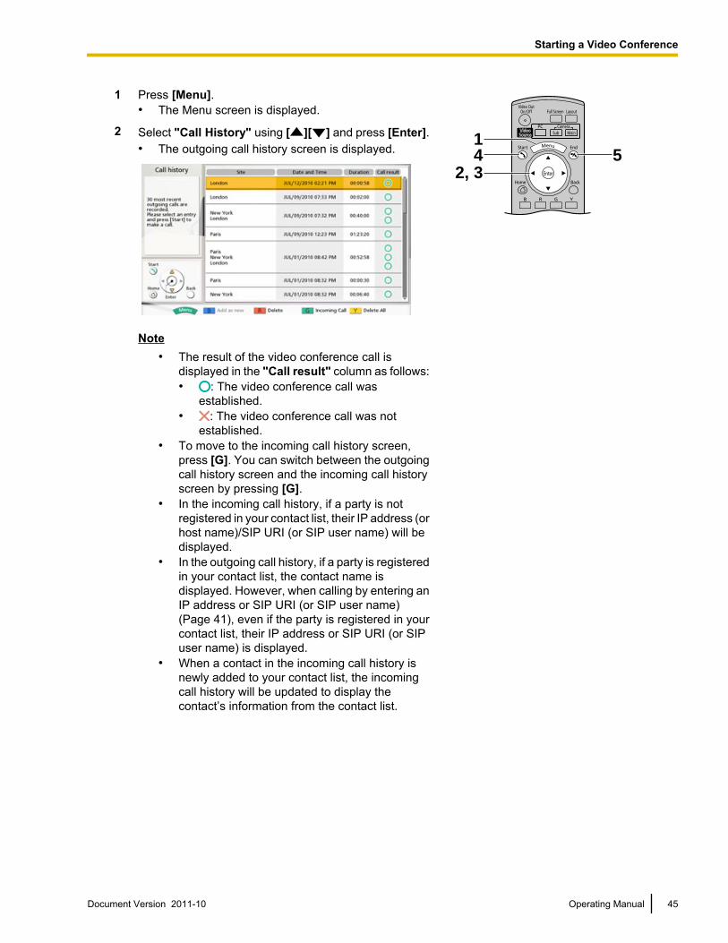
1 Press [Menu].• The Menu screen is displayed.
4 52, 3
12 Select "Call History" using [ ][ ] and press [Enter].
• The outgoing call history screen is displayed.
Note• The result of the video conference call is
displayed in the "Call result" column as follows:• : The video conference call was
established.• : The video conference call was not
established.• To move to the incoming call history screen,
press [G]. You can switch between the outgoingcall history screen and the incoming call historyscreen by pressing [G].
• In the incoming call history, if a party is notregistered in your contact list, their IP address (orhost name)/SIP URI (or SIP user name) will bedisplayed.
• In the outgoing call history, if a party is registeredin your contact list, the contact name isdisplayed. However, when calling by entering anIP address or SIP URI (or SIP user name)(Page 41), even if the party is registered in yourcontact list, their IP address or SIP URI (or SIPuser name) is displayed.
• When a contact in the incoming call history isnewly added to your contact list, the incomingcall history will be updated to display thecontact’s information from the contact list.
Document Version 2011-10 Operating Manual 45
Starting a Video Conference
• When a party that is not registered in yourcontact list is selected, if you press [B], thecontact list registration screen will be displayedand a new contact can be registered(Page 86). If a host name is displayed in the"Site" column, the party cannot be registered inyour contact list. Also, you may not be able toregister a SIP URI (or SIP user name) from theincoming call history to the contact list for areason such as non-compliance with the RFC. Inthis case, contact your network administrator.
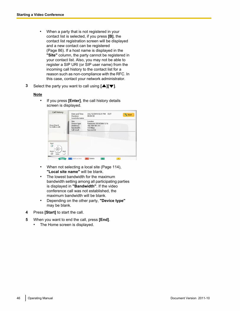
3 Select the party you want to call using [ ][ ].
Note• If you press [Enter], the call history details
screen is displayed.
• When not selecting a local site (Page 114),"Local site name" will be blank.
• The lowest bandwidth for the maximumbandwidth setting among all participating partiesis displayed in "Bandwidth". If the videoconference call was not established, themaximum bandwidth will be blank.
• Depending on the other party, "Device type"may be blank.
4 Press [Start] to start the call.
5 When you want to end the call, press [End].• The Home screen is displayed.
46 Operating Manual Document Version 2011-10
Starting a Video Conference
Answering a Video Conference CallDepending on your setting, you can either respond to a request to participate in a video conference callmanually (manual answer) or automatically (automatic answer) (Page 90).
Note• Make sure that peripheral devices (e.g., display, main video camera) are turned on.
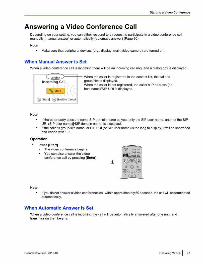
When Manual Answer is SetWhen a video conference call is incoming there will be an incoming call ring, and a dialog box is displayed.
When the caller is registered in the contact list, the caller’s
group/site is displayed.
When the caller is not registered, the caller’s IP address (or
host name)/SIP-URI is displayed.
Note• If the other party uses the same SIP domain name as you, only the SIP user name, and not the SIP
URI (SIP user name@SIP domain name) is displayed.• If the caller’s group/site name, or SIP URI (or SIP user name) is too long to display, it will be shortened
and ended with "..." .
Operation1 Press [Start].
• The video conference begins.• You can also answer the video
conference call by pressing [Enter].1
Note• If you do not answer a video conference call within approximately 60 seconds, the call will be terminated
automatically.
When Automatic Answer is SetWhen a video conference call is incoming the call will be automatically answered after one ring, andtransmission then begins.
Document Version 2011-10 Operating Manual 47
Starting a Video Conference
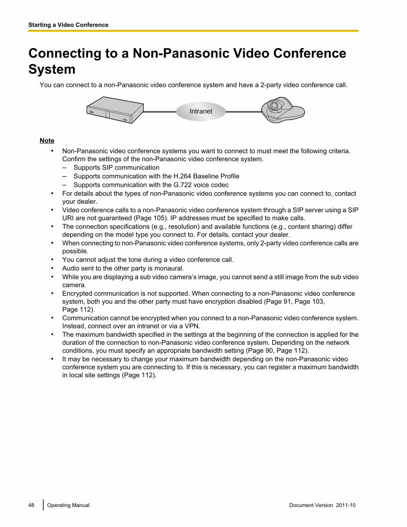
Connecting to a Non-Panasonic Video ConferenceSystem
You can connect to a non-Panasonic video conference system and have a 2-party video conference call.
Intranet
Note• Non-Panasonic video conference systems you want to connect to must meet the following criteria.
Confirm the settings of the non-Panasonic video conference system.– Supports SIP communication– Supports communication with the H.264 Baseline Profile– Supports communication with the G.722 voice codec
• For details about the types of non-Panasonic video conference systems you can connect to, contactyour dealer.
• Video conference calls to a non-Panasonic video conference system through a SIP server using a SIPURI are not guaranteed (Page 105). IP addresses must be specified to make calls.
• The connection specifications (e.g., resolution) and available functions (e.g., content sharing) differdepending on the model type you connect to. For details, contact your dealer.
• When connecting to non-Panasonic video conference systems, only 2-party video conference calls arepossible.
• You cannot adjust the tone during a video conference call.• Audio sent to the other party is monaural.• While you are displaying a sub video camera’s image, you cannot send a still image from the sub video
camera.• Encrypted communication is not supported. When connecting to a non-Panasonic video conference
system, both you and the other party must have encryption disabled (Page 91, Page 103,Page 112).
• Communication cannot be encrypted when you connect to a non-Panasonic video conference system.Instead, connect over an intranet or via a VPN.
• The maximum bandwidth specified in the settings at the beginning of the connection is applied for theduration of the connection to non-Panasonic video conference system. Depending on the networkconditions, you must specify an appropriate bandwidth setting (Page 90, Page 112).
• It may be necessary to change your maximum bandwidth depending on the non-Panasonic videoconference system you are connecting to. If this is necessary, you can register a maximum bandwidthin local site settings (Page 112).
48 Operating Manual Document Version 2011-10
Starting a Video Conference
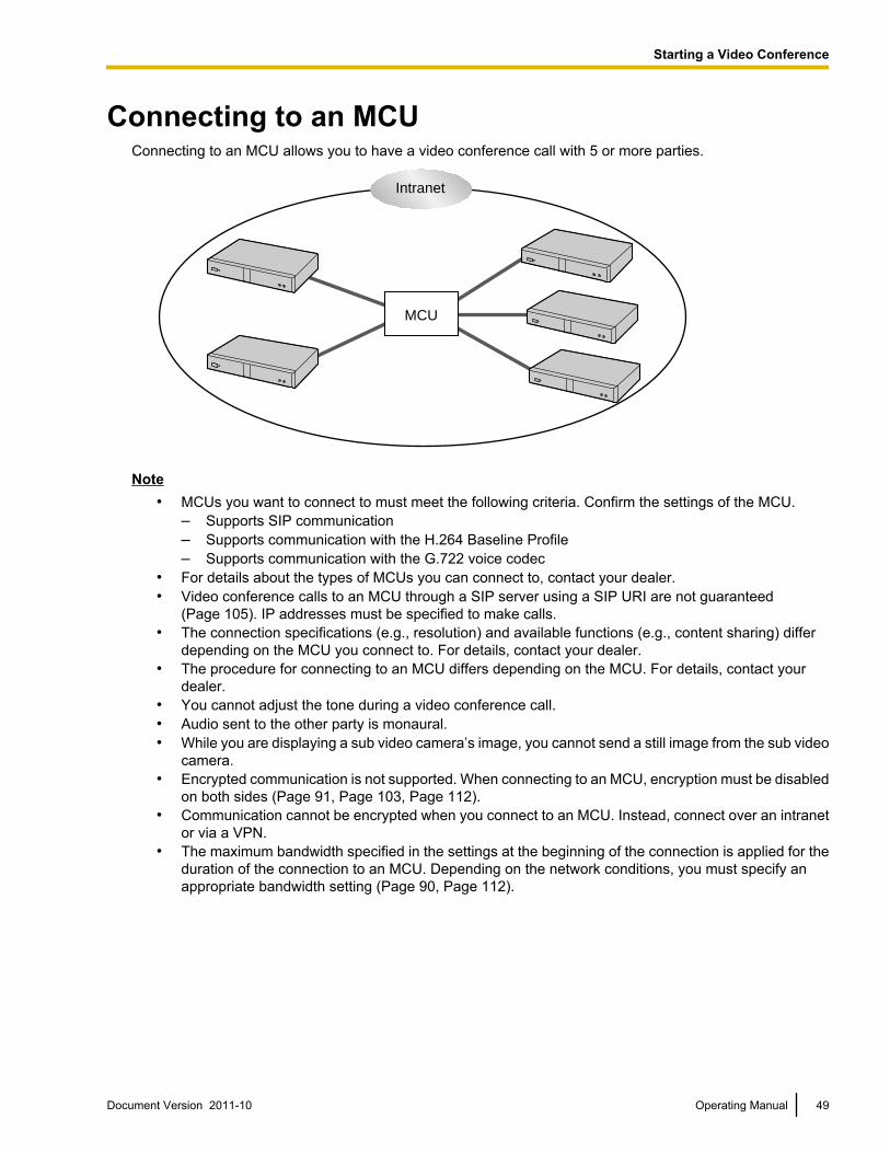
Connecting to an MCUConnecting to an MCU allows you to have a video conference call with 5 or more parties.
MCU
Intranet
Note• MCUs you want to connect to must meet the following criteria. Confirm the settings of the MCU.
– Supports SIP communication– Supports communication with the H.264 Baseline Profile– Supports communication with the G.722 voice codec
• For details about the types of MCUs you can connect to, contact your dealer.• Video conference calls to an MCU through a SIP server using a SIP URI are not guaranteed
(Page 105). IP addresses must be specified to make calls.• The connection specifications (e.g., resolution) and available functions (e.g., content sharing) differ
depending on the MCU you connect to. For details, contact your dealer.• The procedure for connecting to an MCU differs depending on the MCU. For details, contact your
dealer.• You cannot adjust the tone during a video conference call.• Audio sent to the other party is monaural.• While you are displaying a sub video camera’s image, you cannot send a still image from the sub video
camera.• Encrypted communication is not supported. When connecting to an MCU, encryption must be disabled
on both sides (Page 91, Page 103, Page 112).• Communication cannot be encrypted when you connect to an MCU. Instead, connect over an intranet
or via a VPN.• The maximum bandwidth specified in the settings at the beginning of the connection is applied for the
duration of the connection to an MCU. Depending on the network conditions, you must specify anappropriate bandwidth setting (Page 90, Page 112).
Document Version 2011-10 Operating Manual 49
Starting a Video Conference
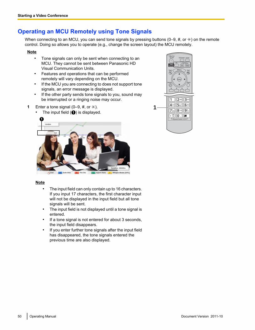
Operating an MCU Remotely using Tone SignalsWhen connecting to an MCU, you can send tone signals by pressing buttons (0–9, #, or ) on the remotecontrol. Doing so allows you to operate (e.g., change the screen layout) the MCU remotely.
Note• Tone signals can only be sent when connecting to an
MCU. They cannot be sent between Panasonic HDVisual Communication Units.
• Features and operations that can be performedremotely will vary depending on the MCU.
• If the MCU you are connecting to does not support tonesignals, an error message is displayed.
• If the other party sends tone signals to you, sound maybe interrupted or a ringing noise may occur.
11 Enter a tone signal (0–9, #, or ).• The input field (A) is displayed.A
Note• The input field can only contain up to 16 characters.
If you input 17 characters, the first character inputwill not be displayed in the input field but all tonesignals will be sent.
• The input field is not displayed until a tone signal isentered.
• If a tone signal is not entered for about 3 seconds,the input field disappears.
• If you enter further tone signals after the input fieldhas disappeared, the tone signals entered theprevious time are also displayed.
50 Operating Manual Document Version 2011-10
Starting a Video Conference
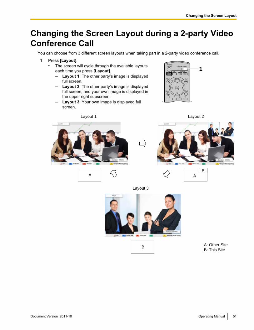
Changing the Screen Layout during a 2-party VideoConference Call
You can choose from 3 different screen layouts when taking part in a 2-party video conference call.
1 Press [Layout].• The screen will cycle through the available layouts
each time you press [Layout].– Layout 1: The other party’s image is displayed
full screen.– Layout 2: The other party’s image is displayed
full screen, and your own image is displayed inthe upper right subscreen.
– Layout 3: Your own image is displayed fullscreen.
1
A
B
B
A
Layout 1 Layout 2
Layout 3
A: Other Site
B: This Site
Document Version 2011-10 Operating Manual 51
C
h
a
n
g
i
n
g
t
h
e
S
c
r
e
e
n
L
a
y
o
u
t
Changing the Screen Layout
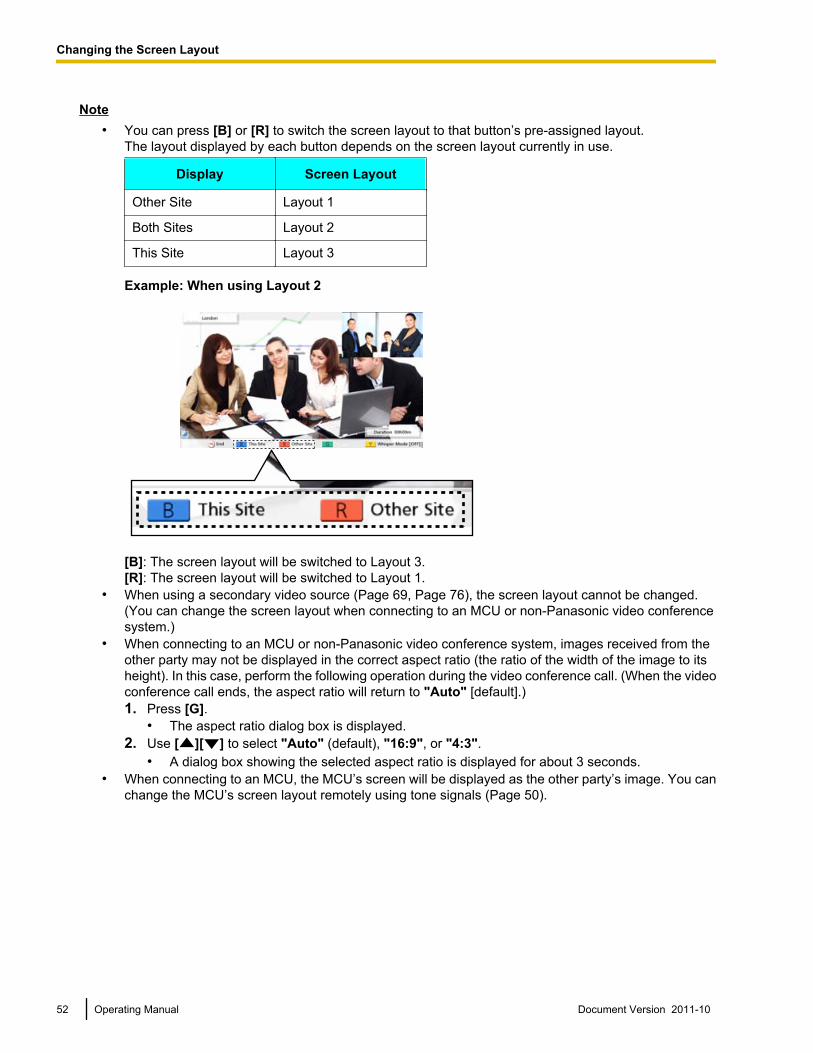
Note• You can press [B] or [R] to switch the screen layout to that button’s pre-assigned layout.
The layout displayed by each button depends on the screen layout currently in use.
Display Screen Layout
Other Site Layout 1
Both Sites Layout 2
This Site Layout 3
Example: When using Layout 2
[B]: The screen layout will be switched to Layout 3.[R]: The screen layout will be switched to Layout 1.
• When using a secondary video source (Page 69, Page 76), the screen layout cannot be changed.(You can change the screen layout when connecting to an MCU or non-Panasonic video conferencesystem.)
• When connecting to an MCU or non-Panasonic video conference system, images received from theother party may not be displayed in the correct aspect ratio (the ratio of the width of the image to itsheight). In this case, perform the following operation during the video conference call. (When the videoconference call ends, the aspect ratio will return to "Auto" [default].)1. Press [G].
• The aspect ratio dialog box is displayed.2. Use [ ][ ] to select "Auto" (default), "16:9", or "4:3".
• A dialog box showing the selected aspect ratio is displayed for about 3 seconds.• When connecting to an MCU, the MCU’s screen will be displayed as the other party’s image. You can
change the MCU’s screen layout remotely using tone signals (Page 50).
52 Operating Manual Document Version 2011-10
Changing the Screen Layout
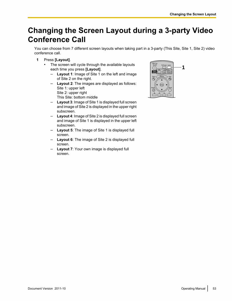
Changing the Screen Layout during a 3-party VideoConference Call
You can choose from 7 different screen layouts when taking part in a 3-party (This Site, Site 1, Site 2) videoconference call.
1 Press [Layout].• The screen will cycle through the available layouts
each time you press [Layout].– Layout 1: Image of Site 1 on the left and image
of Site 2 on the right.– Layout 2: The images are displayed as follows:
Site 1: upper leftSite 2: upper rightThis Site: bottom middle
– Layout 3: Image of Site 1 is displayed full screenand image of Site 2 is displayed in the upper rightsubscreen.
– Layout 4: Image of Site 2 is displayed full screenand image of Site 1 is displayed in the upper leftsubscreen.
– Layout 5: The image of Site 1 is displayed fullscreen.
– Layout 6: The image of Site 2 is displayed fullscreen.
– Layout 7: Your own image is displayed fullscreen.
1
Document Version 2011-10 Operating Manual 53
Changing the Screen Layout
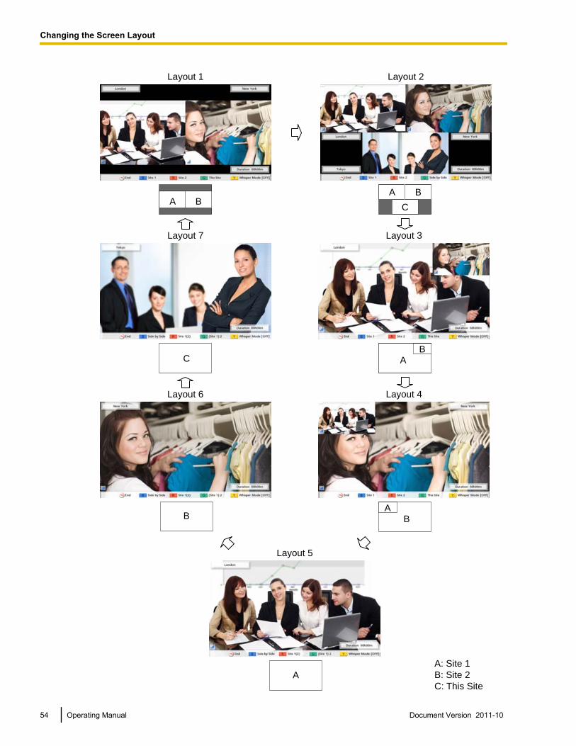
A B
C
Layout 1
Layout 7
Layout 6
B
Layout 2
A
C
B
AB
AB
Layout 3
BA
Layout 4
A
Layout 5
A: Site 1
B: Site 2
C: This Site
54 Operating Manual Document Version 2011-10
Changing the Screen Layout
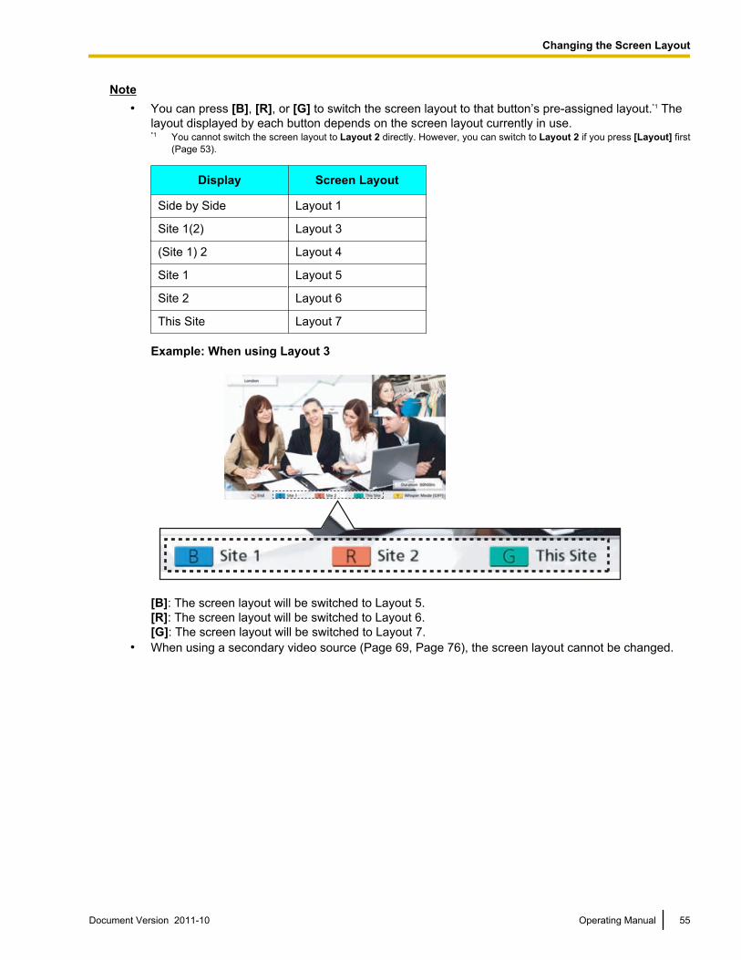
Note• You can press [B], [R], or [G] to switch the screen layout to that button’s pre-assigned layout.*1 The
layout displayed by each button depends on the screen layout currently in use.*1 You cannot switch the screen layout to Layout 2 directly. However, you can switch to Layout 2 if you press [Layout] first
(Page 53).
Display Screen Layout
Side by Side Layout 1
Site 1(2) Layout 3
(Site 1) 2 Layout 4
Site 1 Layout 5
Site 2 Layout 6
This Site Layout 7
Example: When using Layout 3
[B]: The screen layout will be switched to Layout 5.[R]: The screen layout will be switched to Layout 6.[G]: The screen layout will be switched to Layout 7.
• When using a secondary video source (Page 69, Page 76), the screen layout cannot be changed.
Document Version 2011-10 Operating Manual 55
Changing the Screen Layout
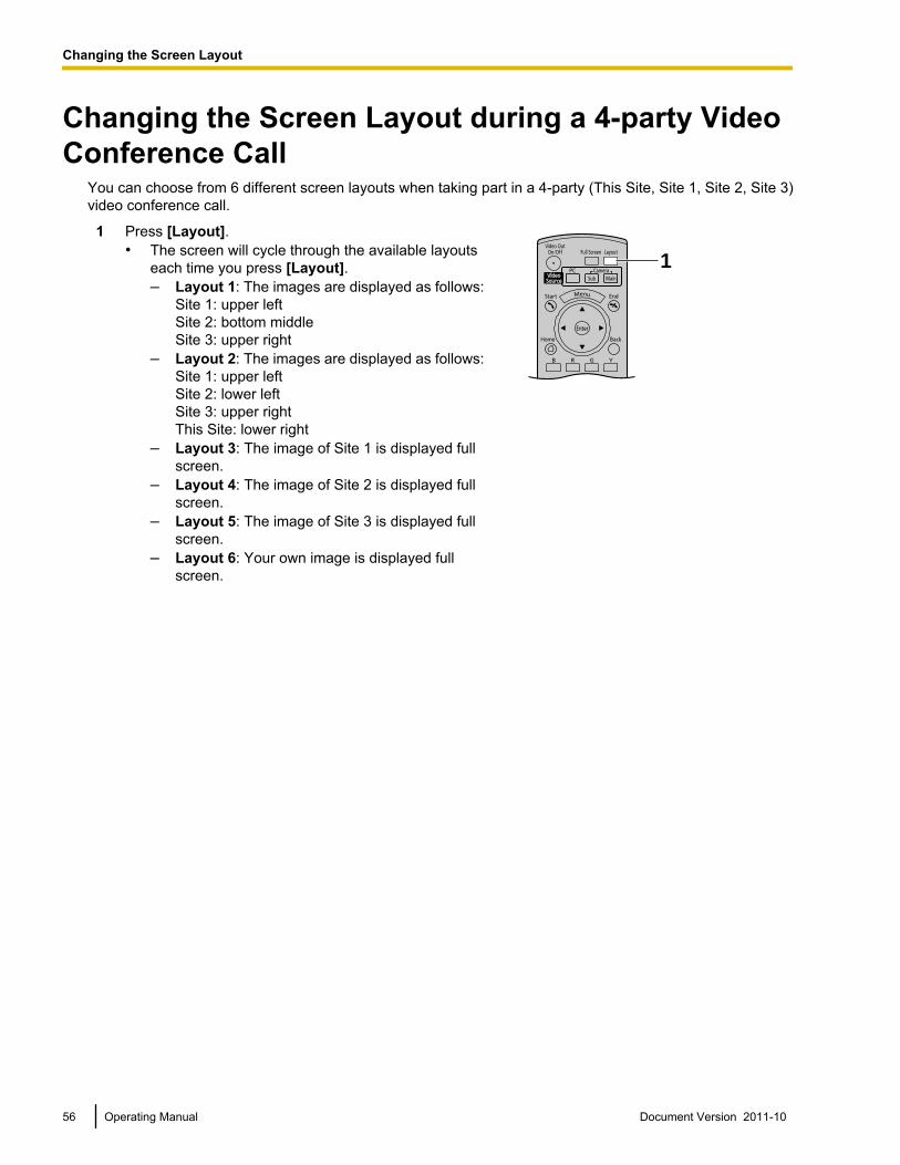
Changing the Screen Layout during a 4-party VideoConference Call
You can choose from 6 different screen layouts when taking part in a 4-party (This Site, Site 1, Site 2, Site 3)video conference call.
1 Press [Layout].• The screen will cycle through the available layouts
each time you press [Layout].– Layout 1: The images are displayed as follows:
Site 1: upper leftSite 2: bottom middleSite 3: upper right
– Layout 2: The images are displayed as follows:Site 1: upper leftSite 2: lower leftSite 3: upper rightThis Site: lower right
– Layout 3: The image of Site 1 is displayed fullscreen.
– Layout 4: The image of Site 2 is displayed fullscreen.
– Layout 5: The image of Site 3 is displayed fullscreen.
– Layout 6: Your own image is displayed fullscreen.
1
56 Operating Manual Document Version 2011-10
Changing the Screen Layout
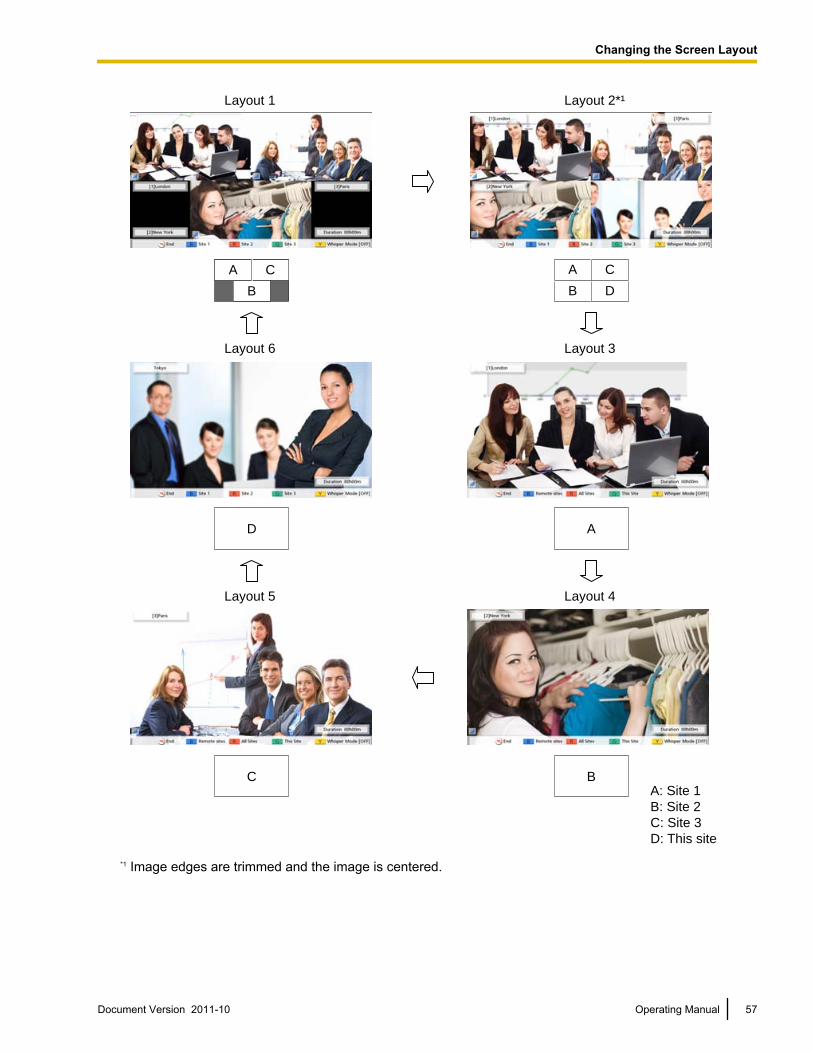
Layout 1 Layout 2*¹
Layout 6 Layout 3
A: Site 1
B: Site 2
C: Site 3
D: This site
Layout 4Layout 5
B D
A CA
B
C
AD
BC
*1 Image edges are trimmed and the image is centered.
Document Version 2011-10 Operating Manual 57
Changing the Screen Layout
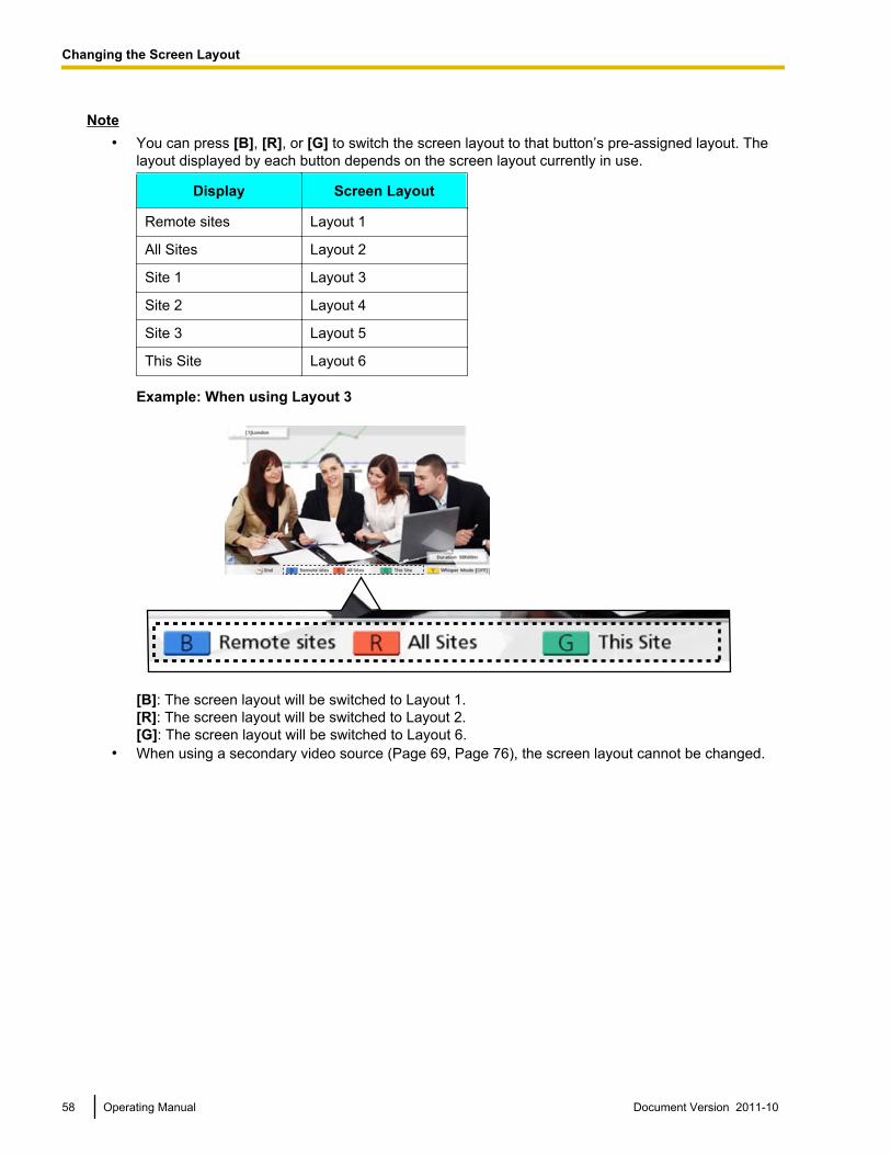
Note• You can press [B], [R], or [G] to switch the screen layout to that button’s pre-assigned layout. The
layout displayed by each button depends on the screen layout currently in use.
Display Screen Layout
Remote sites Layout 1
All Sites Layout 2
Site 1 Layout 3
Site 2 Layout 4
Site 3 Layout 5
This Site Layout 6
Example: When using Layout 3
[B]: The screen layout will be switched to Layout 1.[R]: The screen layout will be switched to Layout 2.[G]: The screen layout will be switched to Layout 6.
• When using a secondary video source (Page 69, Page 76), the screen layout cannot be changed.
58 Operating Manual Document Version 2011-10
Changing the Screen Layout
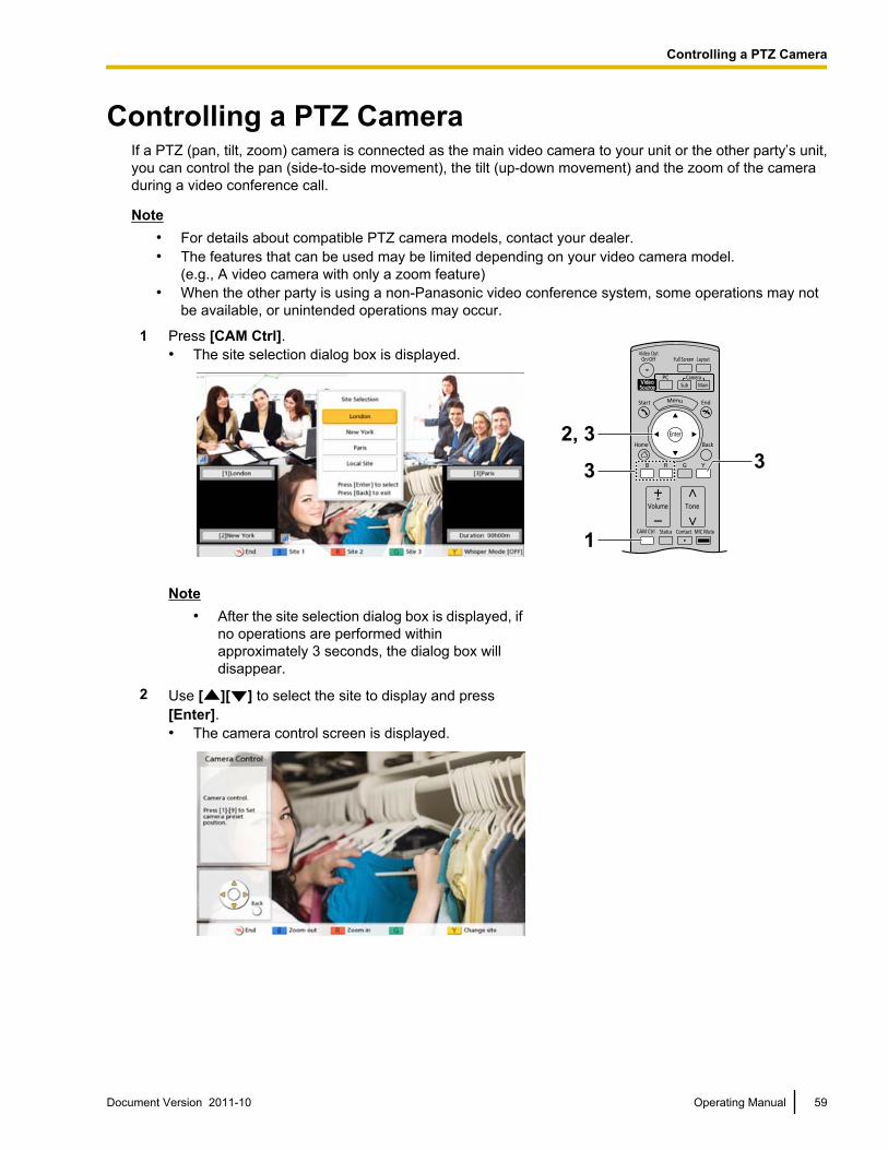
Controlling a PTZ CameraIf a PTZ (pan, tilt, zoom) camera is connected as the main video camera to your unit or the other party’s unit,you can control the pan (side-to-side movement), the tilt (up-down movement) and the zoom of the cameraduring a video conference call.
Note• For details about compatible PTZ camera models, contact your dealer.• The features that can be used may be limited depending on your video camera model.
(e.g., A video camera with only a zoom feature)• When the other party is using a non-Panasonic video conference system, some operations may not
be available, or unintended operations may occur.
1 Press [CAM Ctrl].• The site selection dialog box is displayed.
Note• After the site selection dialog box is displayed, if
no operations are performed withinapproximately 3 seconds, the dialog box willdisappear.
2 Use [ ][ ] to select the site to display and press[Enter].• The camera control screen is displayed.
Document Version 2011-10 Operating Manual 59
C
o
n
t
r
o
l
l
i
n
g
a
P
T
Z
C
a
m
e
r
a
Controlling a PTZ Camera
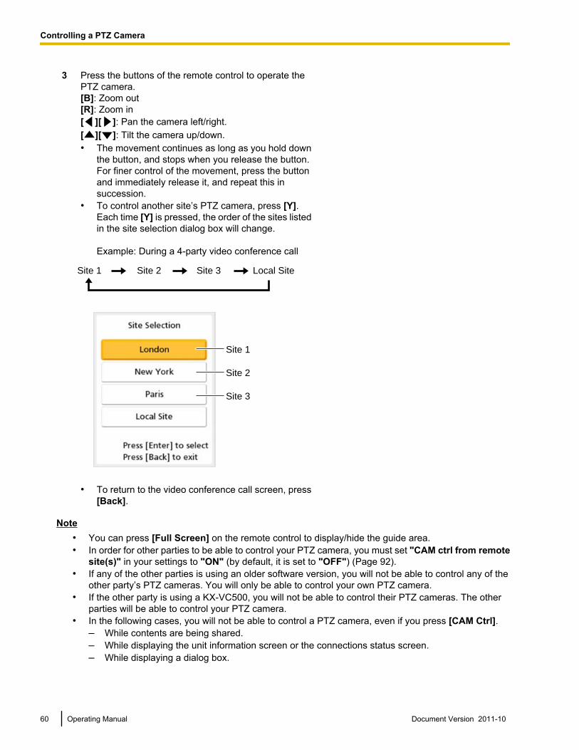
3 Press the buttons of the remote control to operate thePTZ camera.[B]: Zoom out[R]: Zoom in[ ][ ]: Pan the camera left/right.[ ][ ]: Tilt the camera up/down.• The movement continues as long as you hold down
the button, and stops when you release the button.For finer control of the movement, press the buttonand immediately release it, and repeat this insuccession.
• To control another site’s PTZ camera, press [Y].Each time [Y] is pressed, the order of the sites listedin the site selection dialog box will change.
Example: During a 4-party video conference call
Site 1
Site 1
Site 2
Site 3
Site 2 Site 3 Local Site
• To return to the video conference call screen, press[Back].
Note• You can press [Full Screen] on the remote control to display/hide the guide area.• In order for other parties to be able to control your PTZ camera, you must set "CAM ctrl from remote
site(s)" in your settings to "ON" (by default, it is set to "OFF") (Page 92).• If any of the other parties is using an older software version, you will not be able to control any of the
other party’s PTZ cameras. You will only be able to control your own PTZ camera.• If the other party is using a KX-VC500, you will not be able to control their PTZ cameras. The other
parties will be able to control your PTZ camera.• In the following cases, you will not be able to control a PTZ camera, even if you press [CAM Ctrl].
– While contents are being shared.– While displaying the unit information screen or the connections status screen.– While displaying a dialog box.
60 Operating Manual Document Version 2011-10
Controlling a PTZ Camera
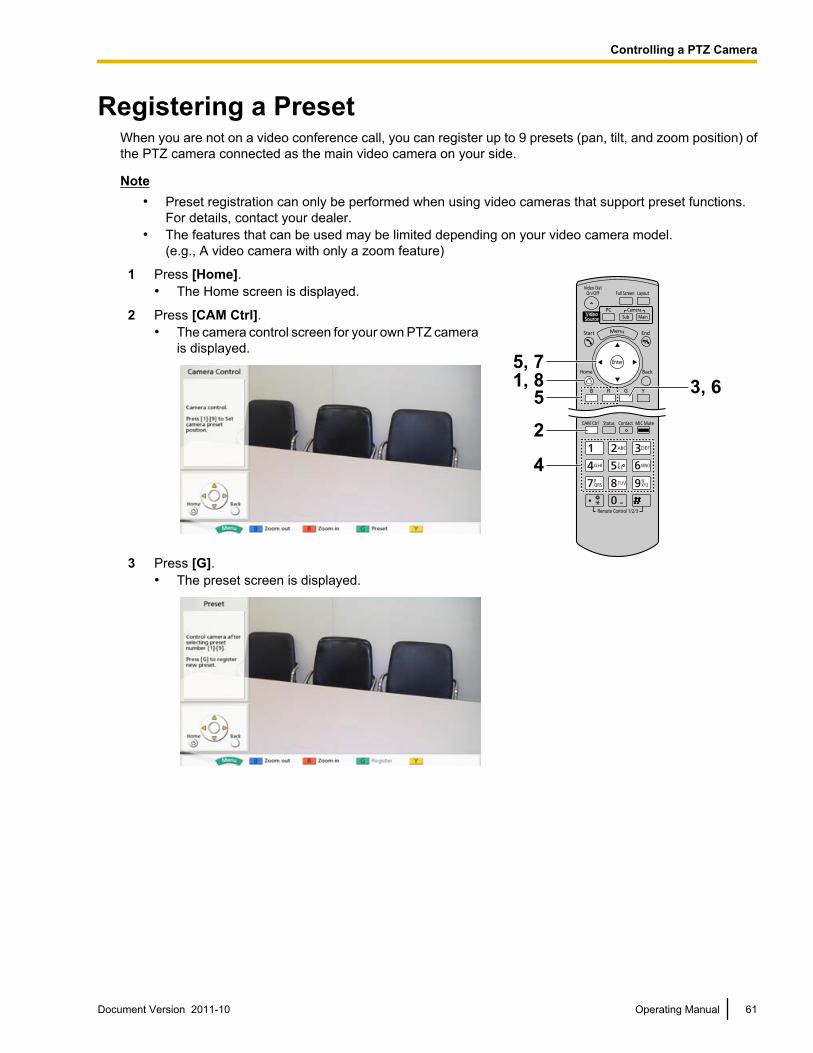
Registering a PresetWhen you are not on a video conference call, you can register up to 9 presets (pan, tilt, and zoom position) ofthe PTZ camera connected as the main video camera on your side.
Note• Preset registration can only be performed when using video cameras that support preset functions.
For details, contact your dealer.• The features that can be used may be limited depending on your video camera model.
(e.g., A video camera with only a zoom feature)
1 Press [Home].• The Home screen is displayed.
2 Press [CAM Ctrl].• The camera control screen for your own PTZ camera
is displayed.
3 Press [G].• The preset screen is displayed.
Document Version 2011-10 Operating Manual 61
Controlling a PTZ Camera
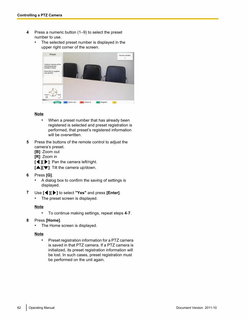
4 Press a numeric button (1–9) to select the presetnumber to use.• The selected preset number is displayed in the
upper right corner of the screen.
Note• When a preset number that has already been
registered is selected and preset registration isperformed, that preset’s registered informationwill be overwritten.
5 Press the buttons of the remote control to adjust thecamera’s preset.[B]: Zoom out[R]: Zoom in[ ][ ]: Pan the camera left/right.[ ][ ]: Tilt the camera up/down.
6 Press [G].• A dialog box to confirm the saving of settings is
displayed.
7 Use [ ][ ] to select "Yes" and press [Enter].• The preset screen is displayed.
Note• To continue making settings, repeat steps 4-7.
8 Press [Home].• The Home screen is displayed.
Note• Preset registration information for a PTZ camera
is saved in that PTZ camera. If a PTZ camera isinitialized, its preset registration information willbe lost. In such cases, preset registration mustbe performed on the unit again.
62 Operating Manual Document Version 2011-10
Controlling a PTZ Camera
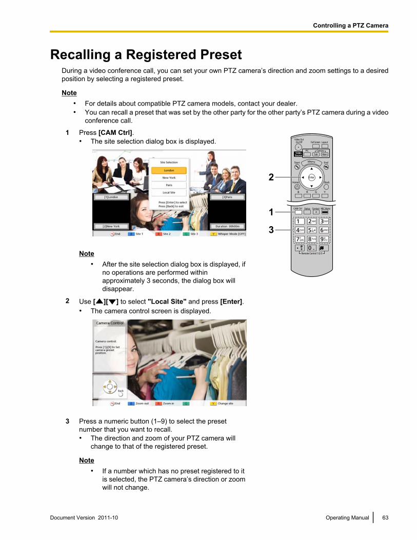
Recalling a Registered PresetDuring a video conference call, you can set your own PTZ camera’s direction and zoom settings to a desiredposition by selecting a registered preset.
Note• For details about compatible PTZ camera models, contact your dealer.• You can recall a preset that was set by the other party for the other party’s PTZ camera during a video
conference call.
1 Press [CAM Ctrl].• The site selection dialog box is displayed.
Note• After the site selection dialog box is displayed, if
no operations are performed withinapproximately 3 seconds, the dialog box willdisappear.
2 Use [ ][ ] to select "Local Site" and press [Enter].• The camera control screen is displayed.
3 Press a numeric button (1–9) to select the presetnumber that you want to recall.• The direction and zoom of your PTZ camera will
change to that of the registered preset.
Note• If a number which has no preset registered to it
is selected, the PTZ camera’s direction or zoomwill not change.
Document Version 2011-10 Operating Manual 63
Controlling a PTZ Camera
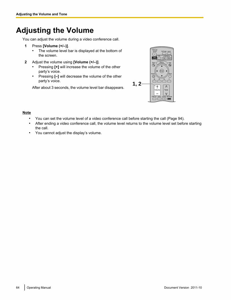
Adjusting the VolumeYou can adjust the volume during a video conference call.
1 Press [Volume (+/–)].• The volume level bar is displayed at the bottom of
the screen.
1, 2
2 Adjust the volume using [Volume (+/–)].• Pressing [+] will increase the volume of the other
party’s voice.• Pressing [–] will decrease the volume of the other
party’s voice.
After about 3 seconds, the volume level bar disappears.
Note• You can set the volume level of a video conference call before starting the call (Page 94).• After ending a video conference call, the volume level returns to the volume level set before starting
the call.• You cannot adjust the display’s volume.
64 Operating Manual Document Version 2011-10
A
d
j
u
s
t
i
n
g
t
h
e
V
o
l
u
m
e
a
n
d
T
o
n
e
Adjusting the Volume and Tone
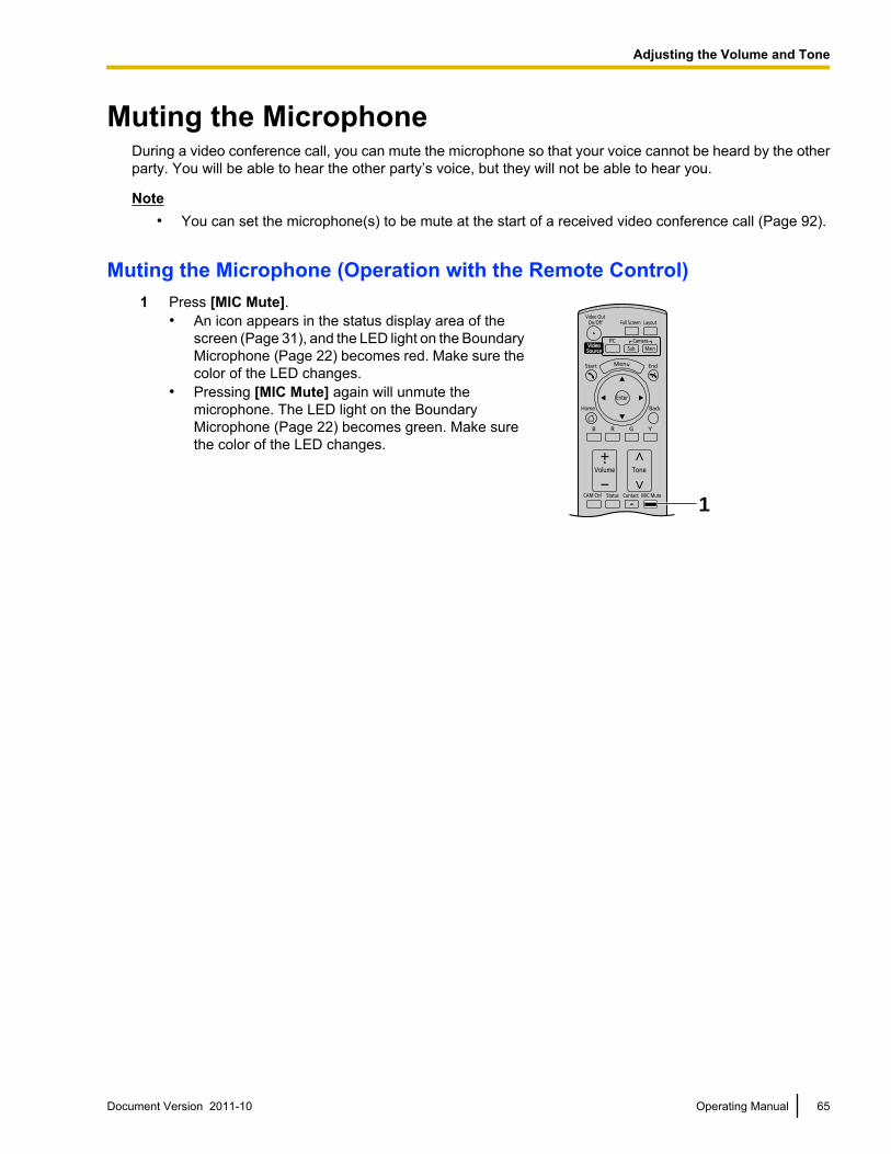
Muting the MicrophoneDuring a video conference call, you can mute the microphone so that your voice cannot be heard by the otherparty. You will be able to hear the other party’s voice, but they will not be able to hear you.
Note• You can set the microphone(s) to be mute at the start of a received video conference call (Page 92).
Muting the Microphone (Operation with the Remote Control)1 Press [MIC Mute].
• An icon appears in the status display area of thescreen (Page 31), and the LED light on the BoundaryMicrophone (Page 22) becomes red. Make sure thecolor of the LED changes.
• Pressing [MIC Mute] again will unmute themicrophone. The LED light on the BoundaryMicrophone (Page 22) becomes green. Make surethe color of the LED changes.
1
Document Version 2011-10 Operating Manual 65
Adjusting the Volume and Tone
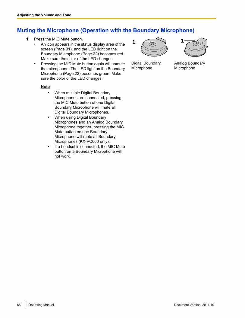
Muting the Microphone (Operation with the Boundary Microphone)1 Press the MIC Mute button.
• An icon appears in the status display area of thescreen (Page 31), and the LED light on theBoundary Microphone (Page 22) becomes red.Make sure the color of the LED changes.
• Pressing the MIC Mute button again will unmutethe microphone. The LED light on the BoundaryMicrophone (Page 22) becomes green. Makesure the color of the LED changes.
Note• When multiple Digital Boundary
Microphones are connected, pressingthe MIC Mute button of one DigitalBoundary Microphone will mute allDigital Boundary Microphones.
• When using Digital BoundaryMicrophones and an Analog BoundaryMicrophone together, pressing the MICMute button on one BoundaryMicrophone will mute all BoundaryMicrophones (KX-VC600 only).
• If a headset is connected, the MIC Mutebutton on a Boundary Microphone willnot work.
1 1
Digital BoundaryMicrophone
Analog BoundaryMicrophone
66 Operating Manual Document Version 2011-10
Adjusting the Volume and Tone
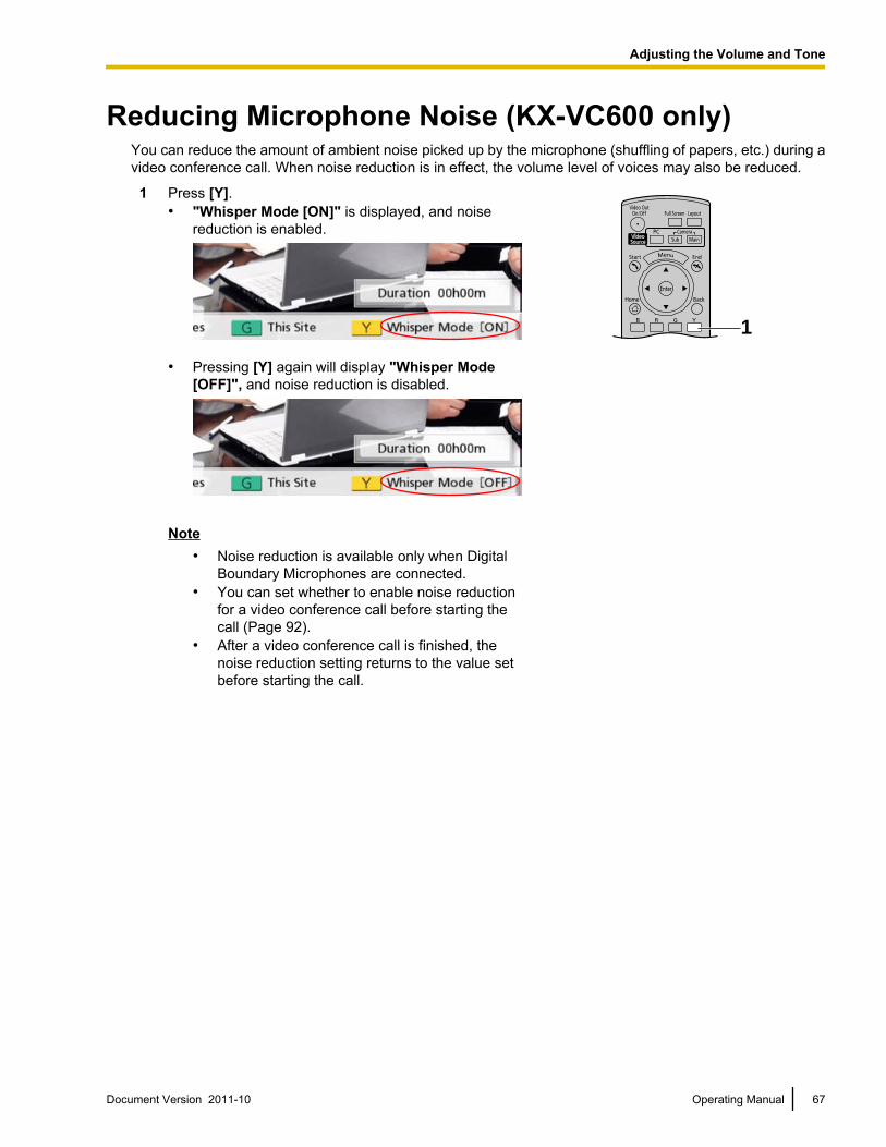
Reducing Microphone Noise (KX-VC600 only)You can reduce the amount of ambient noise picked up by the microphone (shuffling of papers, etc.) during avideo conference call. When noise reduction is in effect, the volume level of voices may also be reduced.
1 Press [Y].• "Whisper Mode [ON]" is displayed, and noise
reduction is enabled.
• Pressing [Y] again will display "Whisper Mode[OFF]", and noise reduction is disabled.
Note• Noise reduction is available only when Digital
Boundary Microphones are connected.• You can set whether to enable noise reduction
for a video conference call before starting thecall (Page 92).
• After a video conference call is finished, thenoise reduction setting returns to the value setbefore starting the call.
1
Document Version 2011-10 Operating Manual 67
Adjusting the Volume and Tone
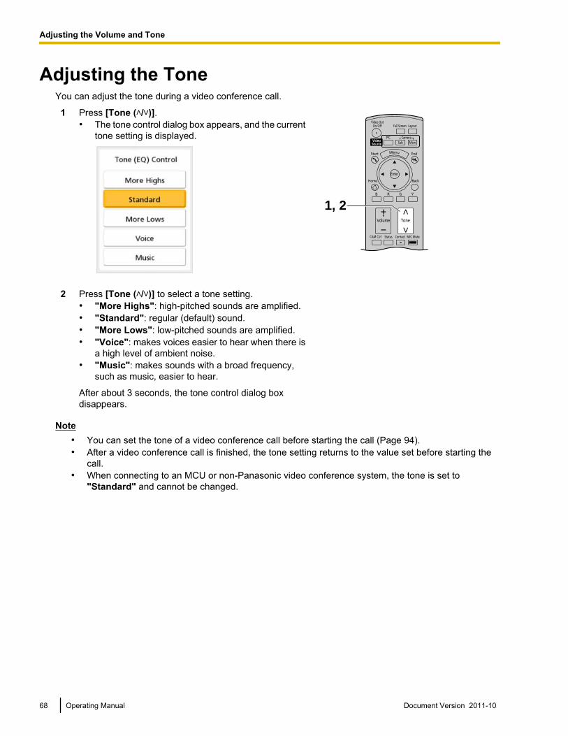
Adjusting the ToneYou can adjust the tone during a video conference call.
1 Press [Tone ( / )].• The tone control dialog box appears, and the current
tone setting is displayed.
1, 2
2 Press [Tone ( / )] to select a tone setting.• "More Highs": high-pitched sounds are amplified.• "Standard": regular (default) sound.• "More Lows": low-pitched sounds are amplified.• "Voice": makes voices easier to hear when there is
a high level of ambient noise.• "Music": makes sounds with a broad frequency,
such as music, easier to hear.
After about 3 seconds, the tone control dialog boxdisappears.
Note• You can set the tone of a video conference call before starting the call (Page 94).• After a video conference call is finished, the tone setting returns to the value set before starting the
call.• When connecting to an MCU or non-Panasonic video conference system, the tone is set to
"Standard" and cannot be changed.
68 Operating Manual Document Version 2011-10
Adjusting the Volume and Tone
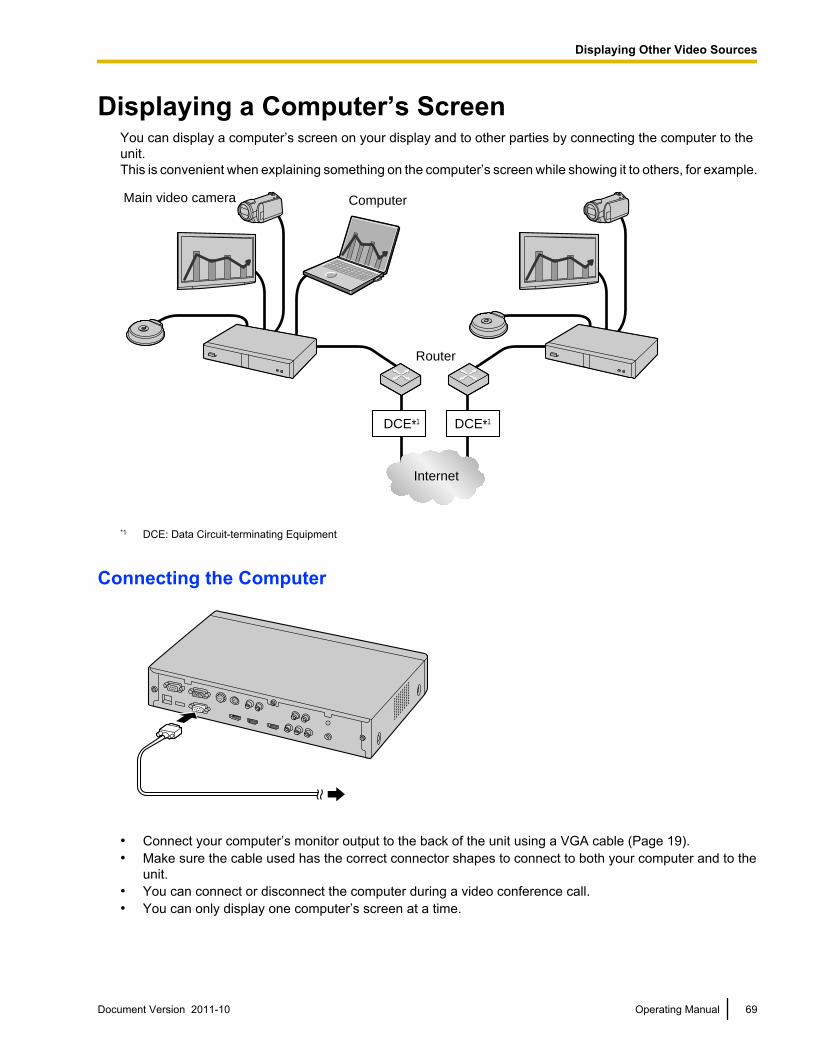
Displaying a Computer’s ScreenYou can display a computer’s screen on your display and to other parties by connecting the computer to theunit.This is convenient when explaining something on the computer’s screen while showing it to others, for example.
DCE*1 DCE*1
Main video camera Computer
Router
Internet
*1 DCE: Data Circuit-terminating Equipment
Connecting the Computer
• Connect your computer’s monitor output to the back of the unit using a VGA cable (Page 19).• Make sure the cable used has the correct connector shapes to connect to both your computer and to the
unit.• You can connect or disconnect the computer during a video conference call.• You can only display one computer’s screen at a time.
Document Version 2011-10 Operating Manual 69
D
i
s
p
l
a
y
i
n
g
O
t
h
e
r
V
i
d
e
o
S
o
u
r
c
e
s
Displaying Other Video Sources
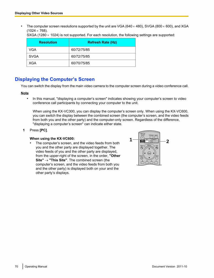
• The computer screen resolutions supported by the unit are VGA (640 ́ 480), SVGA (800 ́ 600), and XGA(1024 ´ 768).SXGA (1280 ´ 1024) is not supported. For each resolution, the following settings are supported:
Resolution Refresh Rate (Hz)
VGA 60/72/75/85
SVGA 60/72/75/85
XGA 60/70/75/85
Displaying the Computer’s ScreenYou can switch the display from the main video camera to the computer screen during a video conference call.
Note• In this manual, "displaying a computer’s screen" indicates showing your computer’s screen to video
conference call participants by connecting your computer to the unit.
When using the KX-VC300, you can display the computer’s screen only. When using the KX-VC600,you can switch the display between the combined screen (the computer’s screen, and the video feedsfrom both you and the other party) and the computer-only screen. Regardless of the difference,"displaying a computer’s screen" can indicate either state.
1 Press [PC].
When using the KX-VC600:• The computer’s screen, and the video feeds from both
you and the other party are displayed together. Thevideo feeds of you and the other party are displayed,from the upper-right of the screen, in the order, "OtherSite" ® "This Site". The combined screen (thecomputer’s screen, and the video feeds from both youand the other party) is displayed both on your and theother party’s displays.
1 2
70 Operating Manual Document Version 2011-10
Displaying Other Video Sources
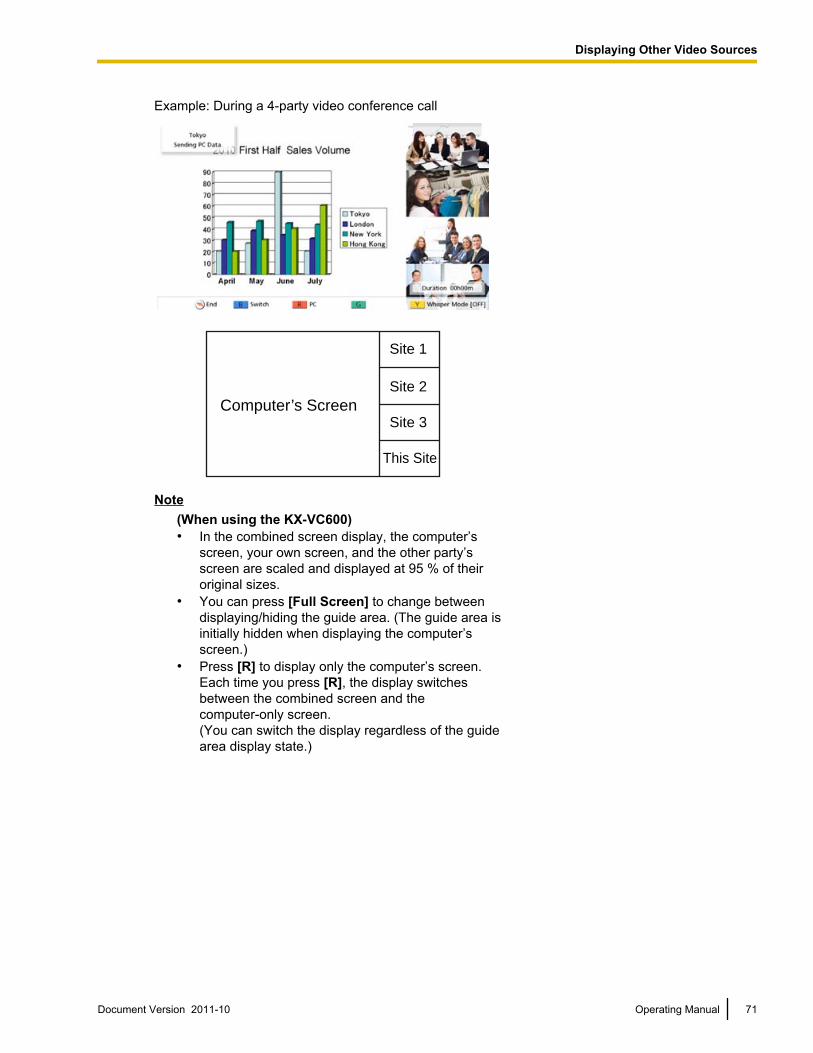
Example: During a 4-party video conference call
Computer’s Screen
Site 1
Site 2
Site 3
This Site
Note(When using the KX-VC600)• In the combined screen display, the computer’s
screen, your own screen, and the other party’sscreen are scaled and displayed at 95 % of theiroriginal sizes.
• You can press [Full Screen] to change betweendisplaying/hiding the guide area. (The guide area isinitially hidden when displaying the computer’sscreen.)
• Press [R] to display only the computer’s screen.Each time you press [R], the display switchesbetween the combined screen and thecomputer-only screen.(You can switch the display regardless of the guidearea display state.)
Document Version 2011-10 Operating Manual 71
Displaying Other Video Sources
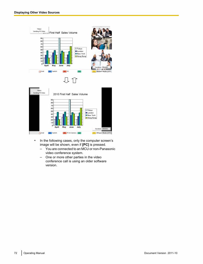
• In the following cases, only the computer screen’simage will be shown, even if [PC] is pressed.– You are connected to an MCU or non-Panasonic
video conference system.– One or more other parties in the video
conference call is using an older softwareversion.
72 Operating Manual Document Version 2011-10
Displaying Other Video Sources
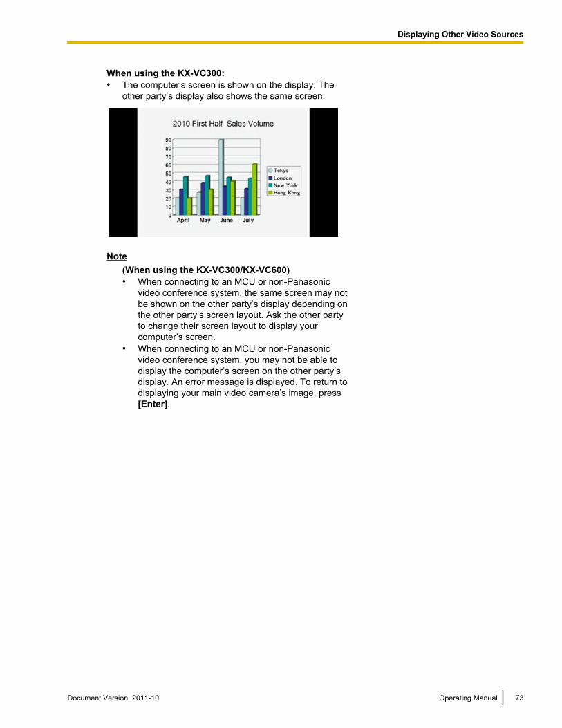
When using the KX-VC300:• The computer’s screen is shown on the display. The
other party’s display also shows the same screen.
Note(When using the KX-VC300/KX-VC600)• When connecting to an MCU or non-Panasonic
video conference system, the same screen may notbe shown on the other party’s display depending onthe other party’s screen layout. Ask the other partyto change their screen layout to display yourcomputer’s screen.
• When connecting to an MCU or non-Panasonicvideo conference system, you may not be able todisplay the computer’s screen on the other party’sdisplay. An error message is displayed. To return todisplaying your main video camera’s image, press[Enter].
Document Version 2011-10 Operating Manual 73
Displaying Other Video Sources
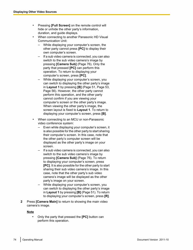
• Pressing [Full Screen] on the remote control willhide or unhide the other party’s information,duration, and guide displays.
• When connecting to another Panasonic HD VisualCommunication Unit:– While displaying your computer’s screen, the
other party cannot press [PC] to display theirown computer’s screen.
– If a sub video camera is connected, you can alsoswitch to the sub video camera’s image bypressing [Camera Sub] (Page 76). Only theparty that pressed [PC] can perform thisoperation. To return to displaying yourcomputer’s screen, press [PC].
– While displaying your computer’s screen, youcan switch to displaying the other party’s imagein Layout 1 by pressing [B] (Page 51, Page 53,Page 56). However, the other party cannotperform this operation, and the other partycannot confirm if you are viewing yourcomputer’s screen or the other party’s image.When viewing the other party’s image, thescreen layout is fixed to Layout 1. To return todisplaying your computer’s screen, press [B].
• When connecting to an MCU or non-Panasonicvideo conference system:– Even while displaying your computer’s screen, it
is also possible for the other party to start sharingtheir computer’s screen. In this case, note thatthe other party’s computer screen will bedisplayed as the other party’s image on yourscreen.
– If a sub video camera is connected, you can alsoswitch to the sub video camera’s image bypressing [Camera Sub] (Page 76). To returnto displaying your computer’s screen, press[PC]. It is also possible for the other party to startsharing their sub video camera’s image. In thiscase, note that the other party’s sub videocamera’s image will be displayed as the otherparty’s image on your screen.
– While displaying your computer’s screen, youcan switch to displaying the other party’s imagein Layout 1 by pressing [B] (Page 51). To returnto displaying your computer’s screen, press [R].
2 Press [Camera Main] to return to showing the main videocamera’s image.
Note• Only the party that pressed the [PC] button can
perform this operation.
74 Operating Manual Document Version 2011-10
Displaying Other Video Sources
Note• On the Home screen, you can also display the
computer’s screen on your display by pressing [PC].While the computer’s screen is displayed, the unit will notenter screen standby mode.To return to the Home screen, press [Camera Main].
Document Version 2011-10 Operating Manual 75
Displaying Other Video Sources
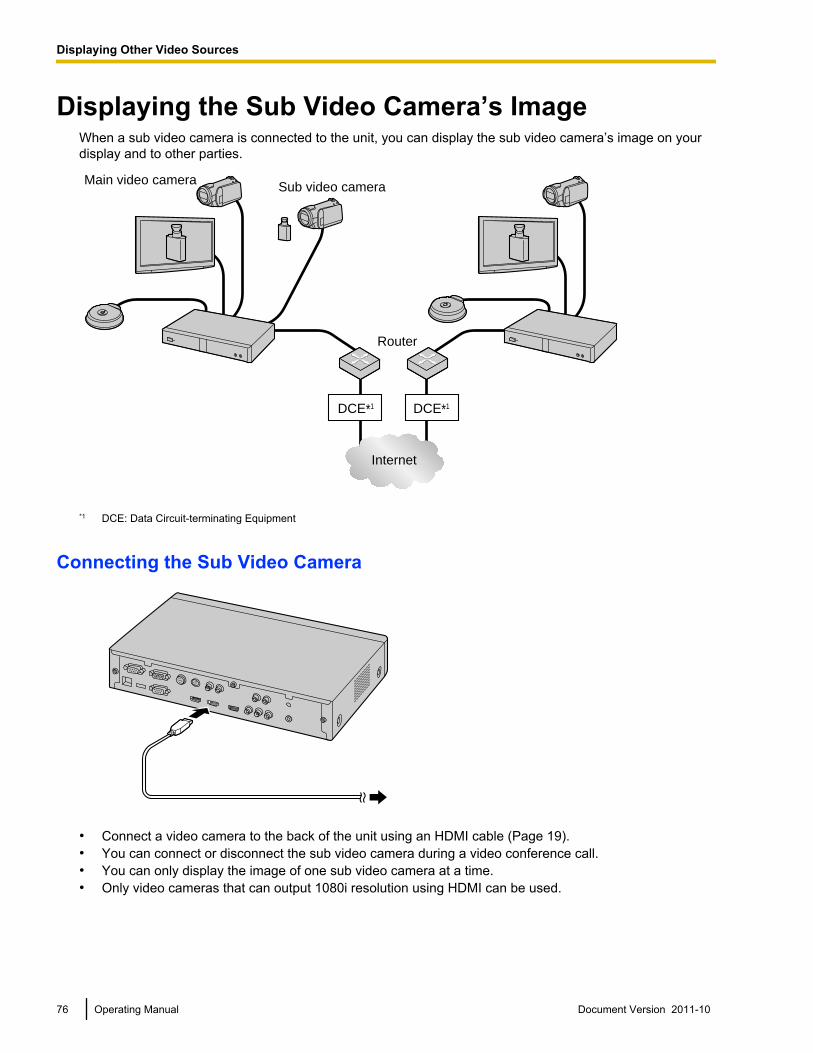
Displaying the Sub Video Camera’s ImageWhen a sub video camera is connected to the unit, you can display the sub video camera’s image on yourdisplay and to other parties.
DCE*1 DCE*1
Main video cameraSub video camera
Router
Internet
*1 DCE: Data Circuit-terminating Equipment
Connecting the Sub Video Camera
• Connect a video camera to the back of the unit using an HDMI cable (Page 19).• You can connect or disconnect the sub video camera during a video conference call.• You can only display the image of one sub video camera at a time.• Only video cameras that can output 1080i resolution using HDMI can be used.
76 Operating Manual Document Version 2011-10
Displaying Other Video Sources
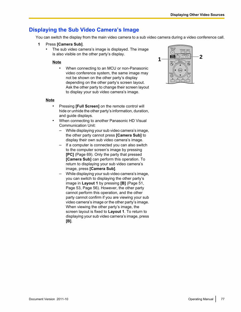
Displaying the Sub Video Camera’s ImageYou can switch the display from the main video camera to a sub video camera during a video conference call.
1 Press [Camera Sub].• The sub video camera’s image is displayed. The image
is also visible on the other party’s display.
Note• When connecting to an MCU or non-Panasonic
video conference system, the same image maynot be shown on the other party’s displaydepending on the other party’s screen layout.Ask the other party to change their screen layoutto display your sub video camera’s image.
1 2
Note• Pressing [Full Screen] on the remote control will
hide or unhide the other party’s information, duration,and guide displays.
• When connecting to another Panasonic HD VisualCommunication Unit:– While displaying your sub video camera’s image,
the other party cannot press [Camera Sub] todisplay their own sub video camera’s image.
– If a computer is connected you can also switchto the computer screen’s image by pressing[PC] (Page 69). Only the party that pressed[Camera Sub] can perform this operation. Toreturn to displaying your sub video camera’simage, press [Camera Sub].
– While displaying your sub video camera’s image,you can switch to displaying the other party’simage in Layout 1 by pressing [B] (Page 51,Page 53, Page 56). However, the other partycannot perform this operation, and the otherparty cannot confirm if you are viewing your subvideo camera’s image or the other party’s image.When viewing the other party’s image, thescreen layout is fixed to Layout 1. To return todisplaying your sub video camera’s image, press[B].
Document Version 2011-10 Operating Manual 77
Displaying Other Video Sources
• When connecting to an MCU or non-Panasonicvideo conference system:– Even while displaying your sub video camera’s
image, it is also possible for the other party tostart sharing their sub video camera’s image. Inthis case, note that the other party’s sub videocamera’s image will be displayed as the otherparty’s image on your screen.
– If a computer is connected, you can also switchto the computer screen’s image by pressing[PC] (Page 69). To return to displaying your subvideo camera’s image, press [Camera Sub]. Itis also possible for the other party to start sharingtheir computer’s screen. In this case, note thatthe other party’s computer screen will bedisplayed as the other party’s image on yourscreen.
– While displaying your sub video camera’simage, you can switch to displaying the otherparty’s image in Layout 1 by pressing [B](Page 51). To return to displaying your sub videocamera’s image, press [R].
2 Press [Camera Main] to return to showing the main videocamera’s image.
Note• Only the party that pressed [Camera Sub] can
perform this operation.
Note• On the Home screen, you can also display the sub video
camera’s image on your display by pressing [CameraSub]. While the sub video camera’s image is displayed,the unit will not enter screen standby mode. To return tothe Home screen, press [Camera Main].
78 Operating Manual Document Version 2011-10
Displaying Other Video Sources
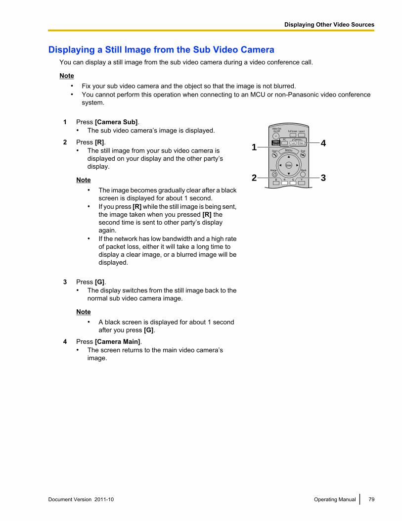
Displaying a Still Image from the Sub Video CameraYou can display a still image from the sub video camera during a video conference call.
Note• Fix your sub video camera and the object so that the image is not blurred.• You cannot perform this operation when connecting to an MCU or non-Panasonic video conference
system.
1 Press [Camera Sub].• The sub video camera’s image is displayed.
1 4
32
2 Press [R].• The still image from your sub video camera is
displayed on your display and the other party’sdisplay.
Note• The image becomes gradually clear after a black
screen is displayed for about 1 second.• If you press [R] while the still image is being sent,
the image taken when you pressed [R] thesecond time is sent to other party’s displayagain.
• If the network has low bandwidth and a high rateof packet loss, either it will take a long time todisplay a clear image, or a blurred image will bedisplayed.
3 Press [G].• The display switches from the still image back to the
normal sub video camera image.
Note• A black screen is displayed for about 1 second
after you press [G].
4 Press [Camera Main].• The screen returns to the main video camera’s
image.
Document Version 2011-10 Operating Manual 79
Displaying Other Video Sources
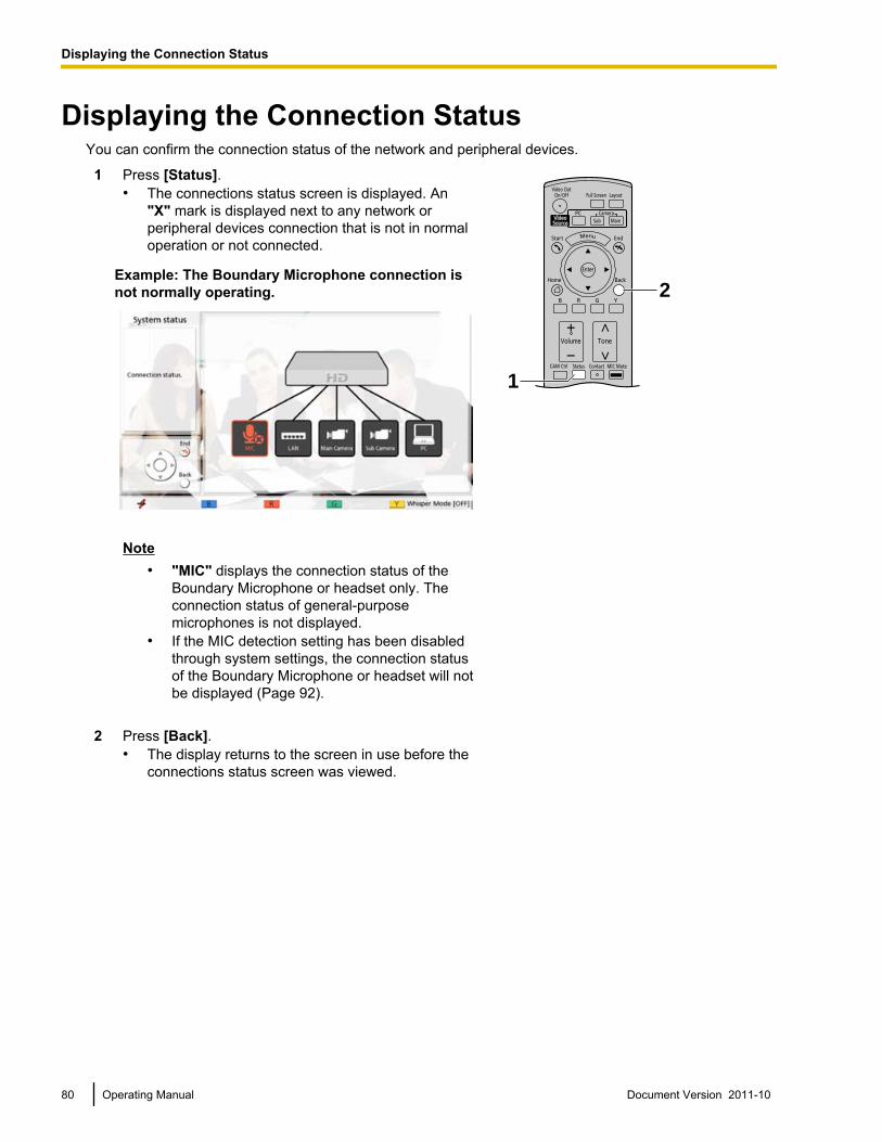
Displaying the Connection StatusYou can confirm the connection status of the network and peripheral devices.
1 Press [Status].• The connections status screen is displayed. An
"X" mark is displayed next to any network orperipheral devices connection that is not in normaloperation or not connected.
Example: The Boundary Microphone connection isnot normally operating.
Note• "MIC" displays the connection status of the
Boundary Microphone or headset only. Theconnection status of general-purposemicrophones is not displayed.
• If the MIC detection setting has been disabledthrough system settings, the connection statusof the Boundary Microphone or headset will notbe displayed (Page 92).
2
1
2 Press [Back].• The display returns to the screen in use before the
connections status screen was viewed.
80 Operating Manual Document Version 2011-10
D
i
s
p
l
a
y
i
n
g
t
h
e
C
o
n
n
e
c
t
i
o
n
S
t
a
t
u
s
Displaying the Connection Status
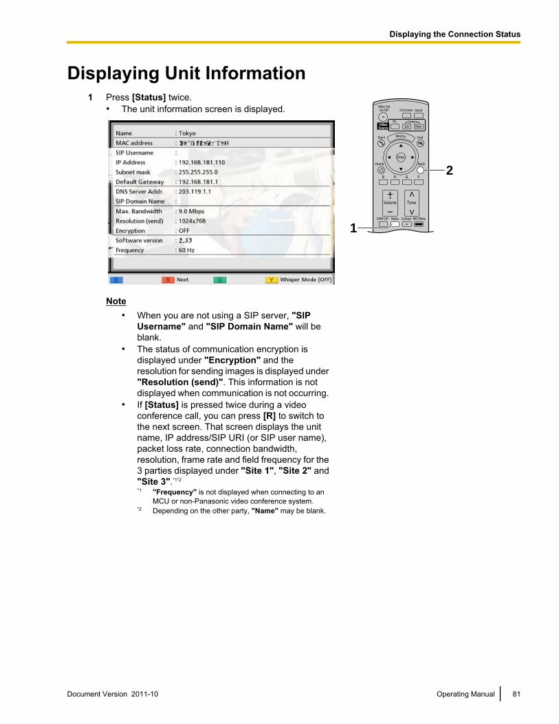
Displaying Unit Information1 Press [Status] twice.
• The unit information screen is displayed.
2
1
Note• When you are not using a SIP server, "SIP
Username" and "SIP Domain Name" will beblank.
• The status of communication encryption isdisplayed under "Encryption" and theresolution for sending images is displayed under"Resolution (send)". This information is notdisplayed when communication is not occurring.
• If [Status] is pressed twice during a videoconference call, you can press [R] to switch tothe next screen. That screen displays the unitname, IP address/SIP URI (or SIP user name),packet loss rate, connection bandwidth,resolution, frame rate and field frequency for the3 parties displayed under "Site 1", "Site 2" and"Site 3".*1*2
*1 "Frequency" is not displayed when connecting to anMCU or non-Panasonic video conference system.
*2 Depending on the other party, "Name" may be blank.
Document Version 2011-10 Operating Manual 81
Displaying the Connection Status
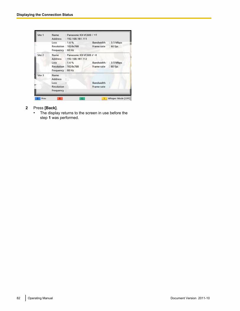
2 Press [Back].• The display returns to the screen in use before the
step 1 was performed.
82 Operating Manual Document Version 2011-10
Displaying the Connection Status
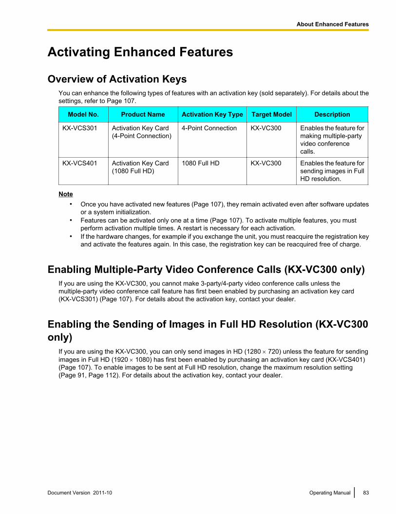
Activating Enhanced Features
Overview of Activation KeysYou can enhance the following types of features with an activation key (sold separately). For details about thesettings, refer to Page 107.
Model No. Product Name Activation Key Type Target Model Description
KX-VCS301 Activation Key Card(4-Point Connection)
4-Point Connection KX-VC300 Enables the feature formaking multiple-partyvideo conferencecalls.
KX-VCS401 Activation Key Card(1080 Full HD)
1080 Full HD KX-VC300 Enables the feature forsending images in FullHD resolution.
Note• Once you have activated new features (Page 107), they remain activated even after software updates
or a system initialization.• Features can be activated only one at a time (Page 107). To activate multiple features, you must
perform activation multiple times. A restart is necessary for each activation.• If the hardware changes, for example if you exchange the unit, you must reacquire the registration key
and activate the features again. In this case, the registration key can be reacquired free of charge.
Enabling Multiple-Party Video Conference Calls (KX-VC300 only)If you are using the KX-VC300, you cannot make 3-party/4-party video conference calls unless themultiple-party video conference call feature has first been enabled by purchasing an activation key card(KX-VCS301) (Page 107). For details about the activation key, contact your dealer.
Enabling the Sending of Images in Full HD Resolution (KX-VC300only)
If you are using the KX-VC300, you can only send images in HD (1280 ´ 720) unless the feature for sendingimages in Full HD (1920 ´ 1080) has first been enabled by purchasing an activation key card (KX-VCS401)(Page 107). To enable images to be sent at Full HD resolution, change the maximum resolution setting(Page 91, Page 112). For details about the activation key, contact your dealer.
Document Version 2011-10 Operating Manual 83
A
b
o
u
t
E
n
h
a
n
c
e
d
F
e
a
t
u
r
e
s
About Enhanced Features
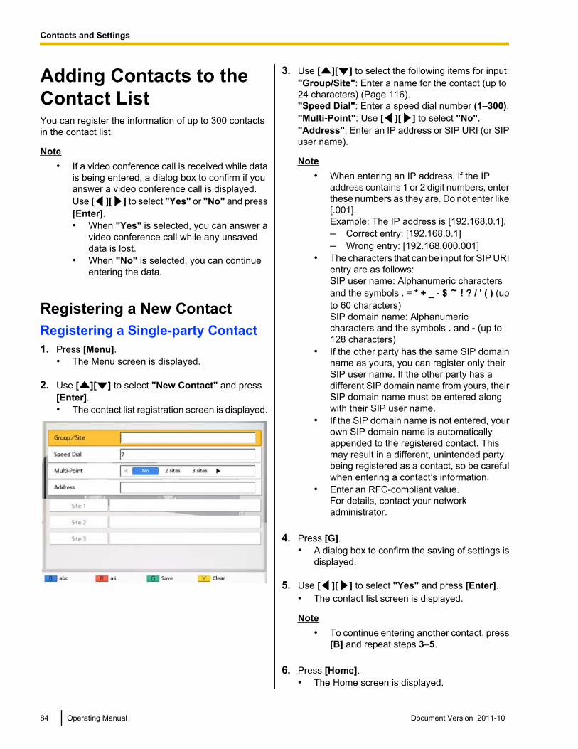
Adding Contacts to theContact ListYou can register the information of up to 300 contactsin the contact list.
Note• If a video conference call is received while data
is being entered, a dialog box to confirm if youanswer a video conference call is displayed.Use [ ][ ] to select "Yes" or "No" and press[Enter].• When "Yes" is selected, you can answer a
video conference call while any unsaveddata is lost.
• When "No" is selected, you can continueentering the data.
Registering a New ContactRegistering a Single-party Contact1. Press [Menu].
• The Menu screen is displayed.
2. Use [ ][ ] to select "New Contact" and press[Enter].• The contact list registration screen is displayed.
3. Use [ ][ ] to select the following items for input:"Group/Site": Enter a name for the contact (up to24 characters) (Page 116)."Speed Dial": Enter a speed dial number (1–300)."Multi-Point": Use [ ][ ] to select "No"."Address": Enter an IP address or SIP URI (or SIPuser name).
Note• When entering an IP address, if the IP
address contains 1 or 2 digit numbers, enterthese numbers as they are. Do not enter like[.001].Example: The IP address is [192.168.0.1].– Correct entry: [192.168.0.1]– Wrong entry: [192.168.000.001]
• The characters that can be input for SIP URIentry are as follows:SIP user name: Alphanumeric charactersand the symbols . = * + _ - $ ! ? / ' ( ) (upto 60 characters)SIP domain name: Alphanumericcharacters and the symbols . and - (up to128 characters)
• If the other party has the same SIP domainname as yours, you can register only theirSIP user name. If the other party has adifferent SIP domain name from yours, theirSIP domain name must be entered alongwith their SIP user name.
• If the SIP domain name is not entered, yourown SIP domain name is automaticallyappended to the registered contact. Thismay result in a different, unintended partybeing registered as a contact, so be carefulwhen entering a contact’s information.
• Enter an RFC-compliant value.For details, contact your networkadministrator.
4. Press [G].• A dialog box to confirm the saving of settings is
displayed.
5. Use [ ][ ] to select "Yes" and press [Enter].• The contact list screen is displayed.
Note• To continue entering another contact, press
[B] and repeat steps 3–5.
6. Press [Home].• The Home screen is displayed.
84 Operating Manual Document Version 2011-10
Contacts and Settings
Contacts and Settings
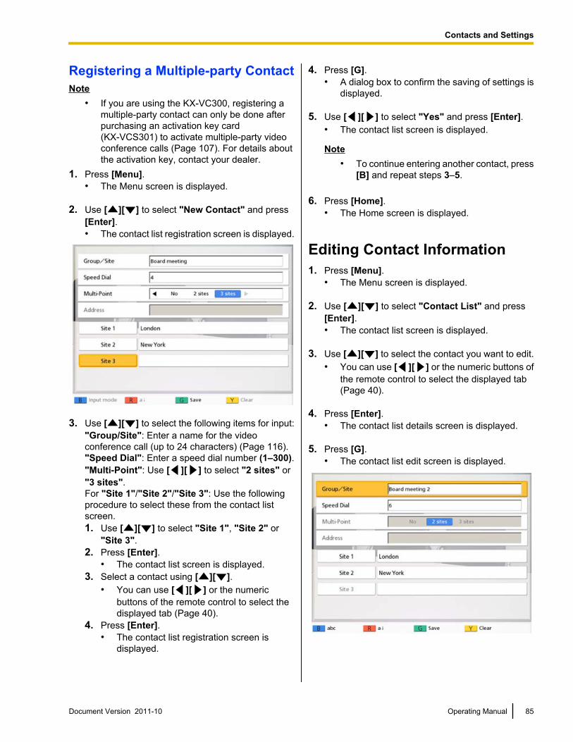
Registering a Multiple-party ContactNote
• If you are using the KX-VC300, registering amultiple-party contact can only be done afterpurchasing an activation key card(KX-VCS301) to activate multiple-party videoconference calls (Page 107). For details aboutthe activation key, contact your dealer.
1. Press [Menu].• The Menu screen is displayed.
2. Use [ ][ ] to select "New Contact" and press[Enter].• The contact list registration screen is displayed.
3. Use [ ][ ] to select the following items for input:"Group/Site": Enter a name for the videoconference call (up to 24 characters) (Page 116)."Speed Dial": Enter a speed dial number (1–300)."Multi-Point": Use [ ][ ] to select "2 sites" or"3 sites".For "Site 1"/"Site 2"/"Site 3": Use the followingprocedure to select these from the contact listscreen.1. Use [ ][ ] to select "Site 1", "Site 2" or
"Site 3".2. Press [Enter].
• The contact list screen is displayed.3. Select a contact using [ ][ ].
• You can use [ ][ ] or the numericbuttons of the remote control to select thedisplayed tab (Page 40).
4. Press [Enter].• The contact list registration screen is
displayed.
4. Press [G].• A dialog box to confirm the saving of settings is
displayed.
5. Use [ ][ ] to select "Yes" and press [Enter].• The contact list screen is displayed.
Note• To continue entering another contact, press
[B] and repeat steps 3–5.
6. Press [Home].• The Home screen is displayed.
Editing Contact Information1. Press [Menu].
• The Menu screen is displayed.
2. Use [ ][ ] to select "Contact List" and press[Enter].• The contact list screen is displayed.
3. Use [ ][ ] to select the contact you want to edit.• You can use [ ][ ] or the numeric buttons of
the remote control to select the displayed tab(Page 40).
4. Press [Enter].• The contact list details screen is displayed.
5. Press [G].• The contact list edit screen is displayed.
Document Version 2011-10 Operating Manual 85
Contacts and Settings
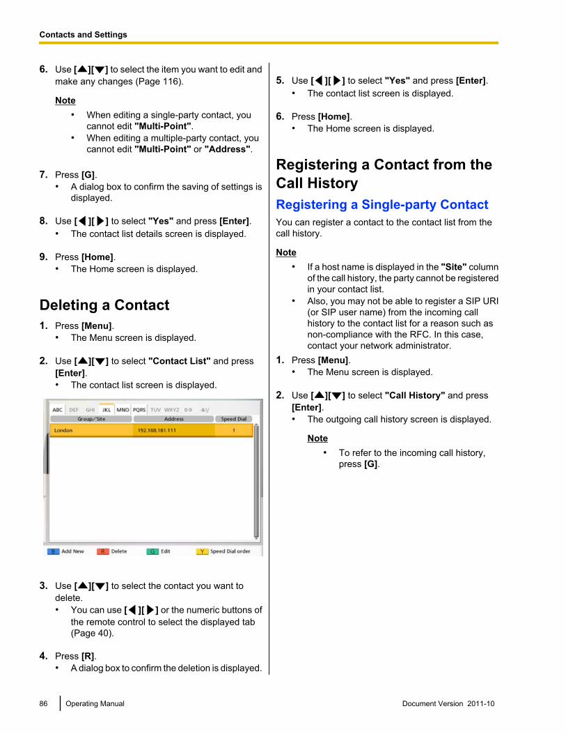
6. Use [ ][ ] to select the item you want to edit andmake any changes (Page 116).
Note• When editing a single-party contact, you
cannot edit "Multi-Point".• When editing a multiple-party contact, you
cannot edit "Multi-Point" or "Address".
7. Press [G].• A dialog box to confirm the saving of settings is
displayed.
8. Use [ ][ ] to select "Yes" and press [Enter].• The contact list details screen is displayed.
9. Press [Home].• The Home screen is displayed.
Deleting a Contact1. Press [Menu].
• The Menu screen is displayed.
2. Use [ ][ ] to select "Contact List" and press[Enter].• The contact list screen is displayed.
3. Use [ ][ ] to select the contact you want todelete.• You can use [ ][ ] or the numeric buttons of
the remote control to select the displayed tab(Page 40).
4. Press [R].• A dialog box to confirm the deletion is displayed.
5. Use [ ][ ] to select "Yes" and press [Enter].• The contact list screen is displayed.
6. Press [Home].• The Home screen is displayed.
Registering a Contact from theCall HistoryRegistering a Single-party ContactYou can register a contact to the contact list from thecall history.
Note• If a host name is displayed in the "Site" column
of the call history, the party cannot be registeredin your contact list.
• Also, you may not be able to register a SIP URI(or SIP user name) from the incoming callhistory to the contact list for a reason such asnon-compliance with the RFC. In this case,contact your network administrator.
1. Press [Menu].• The Menu screen is displayed.
2. Use [ ][ ] to select "Call History" and press[Enter].• The outgoing call history screen is displayed.
Note• To refer to the incoming call history,
press [G].
86 Operating Manual Document Version 2011-10
Contacts and Settings
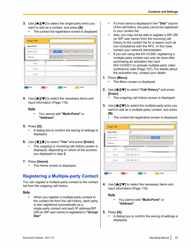
3. Use [ ][ ] to select the single-party entry youwant to add as a contact, and press [B].• The contact list registration screen is displayed.
4. Use [ ][ ] to select the necessary items andinput information (Page 116).
Note• You cannot edit "Multi-Point" or
"Address".
5. Press [G].• A dialog box to confirm the saving of settings is
displayed.
6. Use [ ][ ] to select "Yes" and press [Enter].• The outgoing or incoming call history screen is
displayed, depending on which of the screensyou displayed in step 2.
7. Press [Home].• The Home screen is displayed.
Registering a Multiple-party ContactYou can register a multiple-party contact to the contactlist from the outgoing call history.
Note• When you register a multiple-party contact to
the contact list from the call history, each partyis also registered automatically as asingle-party contact and each IP address/SIPURI (or SIP user name) is registered in "Group/Site".
• If a host name is displayed in the "Site" columnof the call history, the party cannot be registeredin your contact list.
• Also, you may not be able to register a SIP URI(or SIP user name) from the incoming callhistory to the contact list for a reason such asnon-compliance with the RFC. In this case,contact your network administrator.
• If you are using the KX-VC300, registering amultiple-party contact can only be done afterpurchasing an activation key card(KX-VCS301) to activate multiple-party videoconference calls (Page 107). For details aboutthe activation key, contact your dealer.
1. Press [Menu].• The Menu screen is displayed.
2. Use [ ][ ] to select "Call History" and press[Enter].• The outgoing call history screen is displayed.
3. Use [ ][ ] to select the multiple-party entry youwant to add as a multiple-party contact, and press[B].• The contact list registration screen is displayed.
4. Use [ ][ ] to select the necessary items andinput information (Page 116).
Note• You cannot edit "Multi-Point" or
"Address".
5. Press [G].• A dialog box to confirm the saving of settings is
displayed.
Document Version 2011-10 Operating Manual 87
Contacts and Settings
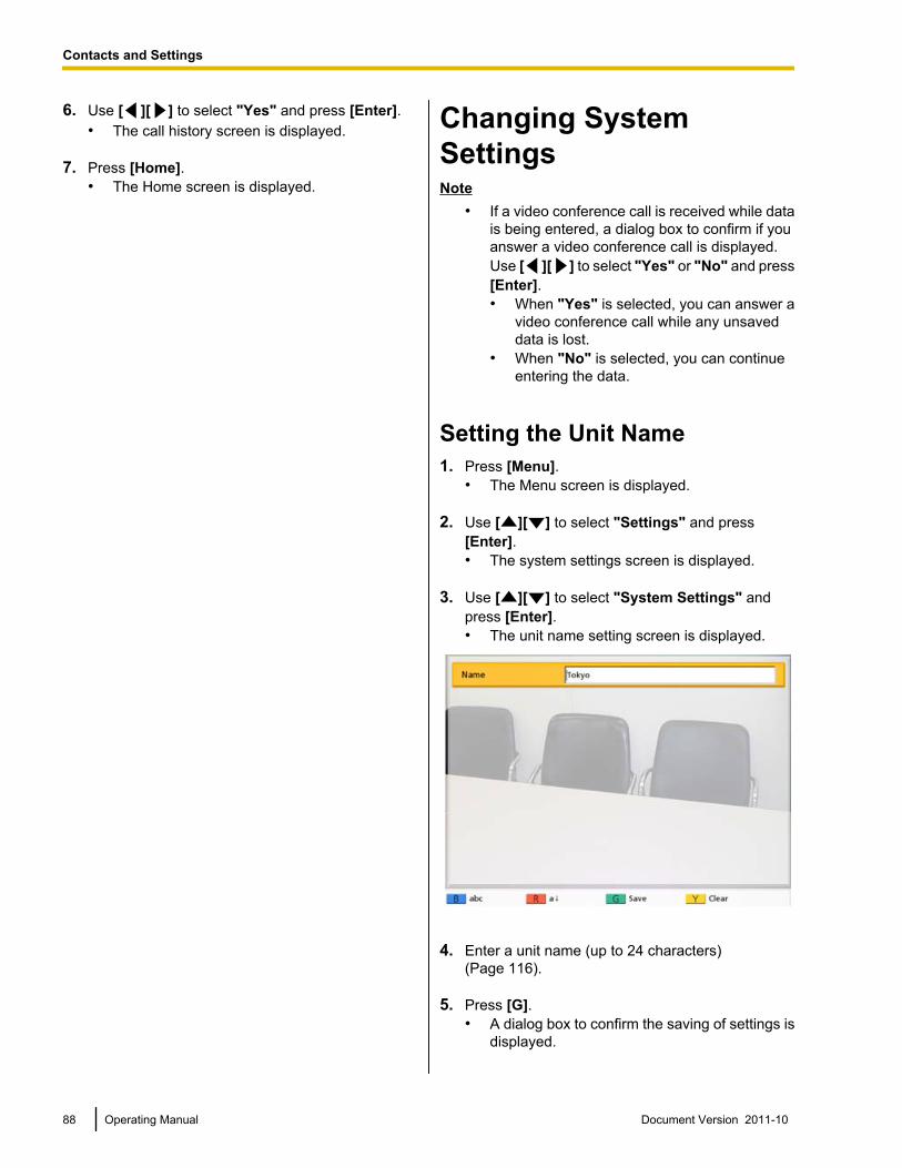
6. Use [ ][ ] to select "Yes" and press [Enter].• The call history screen is displayed.
7. Press [Home].• The Home screen is displayed.
Changing SystemSettingsNote
• If a video conference call is received while datais being entered, a dialog box to confirm if youanswer a video conference call is displayed.Use [ ][ ] to select "Yes" or "No" and press[Enter].• When "Yes" is selected, you can answer a
video conference call while any unsaveddata is lost.
• When "No" is selected, you can continueentering the data.
Setting the Unit Name1. Press [Menu].
• The Menu screen is displayed.
2. Use [ ][ ] to select "Settings" and press[Enter].• The system settings screen is displayed.
3. Use [ ][ ] to select "System Settings" andpress [Enter].• The unit name setting screen is displayed.
4. Enter a unit name (up to 24 characters)(Page 116).
5. Press [G].• A dialog box to confirm the saving of settings is
displayed.
88 Operating Manual Document Version 2011-10
Contacts and Settings
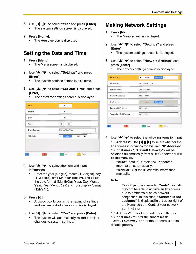
6. Use [ ][ ] to select "Yes" and press [Enter].• The system settings screen is displayed.
7. Press [Home].• The Home screen is displayed.
Setting the Date and Time1. Press [Menu].
• The Menu screen is displayed.
2. Use [ ][ ] to select "Settings" and press[Enter].• The system settings screen is displayed.
3. Use [ ][ ] to select "Set Date/Time" and press[Enter].• The date/time settings screen is displayed.
4. Use [ ][ ] to select the item and inputinformation.• Enter the year (4 digits), month (1–2 digits), day
(1–2 digits), time (24 hour display), and selectthe date format (Month/Day/Year, Day/Month/Year, Year/Month/Day) and hour display format(12h/24h).
5. Press [G].• A dialog box to confirm the saving of settings
and system restart after saving is displayed.
6. Use [ ][ ] to select "Yes" and press [Enter].• The system will automatically restart to reflect
changes to system settings.
Making Network Settings1. Press [Menu].
• The Menu screen is displayed.
2. Use [ ][ ] to select "Settings" and press[Enter].• The system settings screen is displayed.
3. Use [ ][ ] to select "Network Settings" andpress [Enter].• The network settings screen is displayed.
4. Use [ ][ ] to select the following items for input:"IP Address": Use [ ][ ] to select whether theIP address information for this unit ("IP Address","Subnet mask", "Default Gateway") will beobtained automatically from a DHCP server or willbe set manually.– "Auto" (default): Obtain the IP address
information automatically.– "Manual": Set the IP address information
manually.
Note• Even if you have selected "Auto", you still
may not be able to acquire an IP addressdue to problems such as networkcongestion. In this case, "Address is notassigned" is displayed in the upper right ofthe Home screen. Contact your networkadministrator.
"IP Address": Enter the IP address of the unit."Subnet mask": Enter the subnet mask."Default Gateway": Enter the IP address of thedefault gateway.
Document Version 2011-10 Operating Manual 89
Contacts and Settings
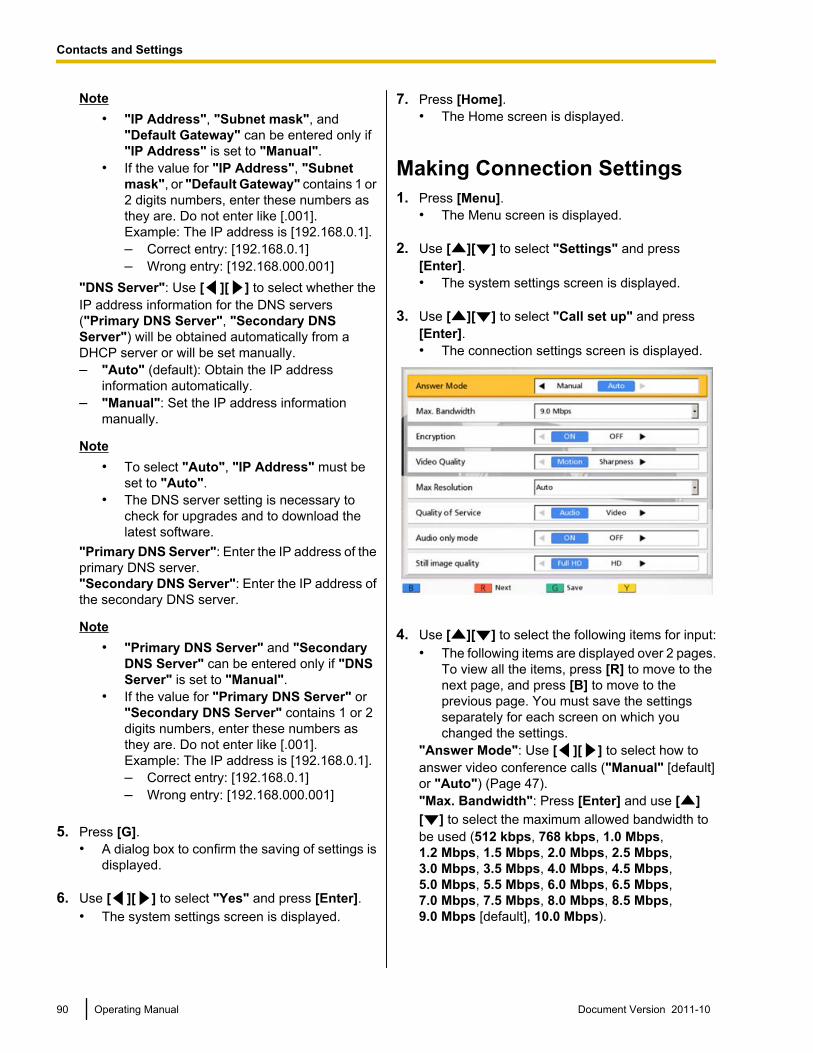
Note• "IP Address", "Subnet mask", and
"Default Gateway" can be entered only if"IP Address" is set to "Manual".
• If the value for "IP Address", "Subnetmask", or "Default Gateway" contains 1 or2 digits numbers, enter these numbers asthey are. Do not enter like [.001].Example: The IP address is [192.168.0.1].– Correct entry: [192.168.0.1]– Wrong entry: [192.168.000.001]
"DNS Server": Use [ ][ ] to select whether theIP address information for the DNS servers("Primary DNS Server", "Secondary DNSServer") will be obtained automatically from aDHCP server or will be set manually.– "Auto" (default): Obtain the IP address
information automatically.– "Manual": Set the IP address information
manually.
Note• To select "Auto", "IP Address" must be
set to "Auto".• The DNS server setting is necessary to
check for upgrades and to download thelatest software.
"Primary DNS Server": Enter the IP address of theprimary DNS server."Secondary DNS Server": Enter the IP address ofthe secondary DNS server.
Note• "Primary DNS Server" and "Secondary
DNS Server" can be entered only if "DNSServer" is set to "Manual".
• If the value for "Primary DNS Server" or"Secondary DNS Server" contains 1 or 2digits numbers, enter these numbers asthey are. Do not enter like [.001].Example: The IP address is [192.168.0.1].– Correct entry: [192.168.0.1]– Wrong entry: [192.168.000.001]
5. Press [G].• A dialog box to confirm the saving of settings is
displayed.
6. Use [ ][ ] to select "Yes" and press [Enter].• The system settings screen is displayed.
7. Press [Home].• The Home screen is displayed.
Making Connection Settings1. Press [Menu].
• The Menu screen is displayed.
2. Use [ ][ ] to select "Settings" and press[Enter].• The system settings screen is displayed.
3. Use [ ][ ] to select "Call set up" and press[Enter].• The connection settings screen is displayed.
4. Use [ ][ ] to select the following items for input:• The following items are displayed over 2 pages.
To view all the items, press [R] to move to thenext page, and press [B] to move to theprevious page. You must save the settingsseparately for each screen on which youchanged the settings.
"Answer Mode": Use [ ][ ] to select how toanswer video conference calls ("Manual" [default]or "Auto") (Page 47)."Max. Bandwidth": Press [Enter] and use [ ][ ] to select the maximum allowed bandwidth tobe used (512 kbps, 768 kbps, 1.0 Mbps,1.2 Mbps, 1.5 Mbps, 2.0 Mbps, 2.5 Mbps,3.0 Mbps, 3.5 Mbps, 4.0 Mbps, 4.5 Mbps,5.0 Mbps, 5.5 Mbps, 6.0 Mbps, 6.5 Mbps,7.0 Mbps, 7.5 Mbps, 8.0 Mbps, 8.5 Mbps,9.0 Mbps [default], 10.0 Mbps).
90 Operating Manual Document Version 2011-10
Contacts and Settings
Note• The maximum bandwidth during a video
conference call adjusts to that of the partythat has set the lowest bandwidth for themaximum bandwidth setting among allparticipating parties.
• You cannot select a value that is higher thanthe maximum bandwidth set by the dealer.For details, contact your dealer.
• When you make a 3-party video conferencecall, select a value of "1.0 Mbps" or higher.Otherwise, the image quality and the soundquality cannot be guaranteed.
• When you make a 4-party video conferencecall, select a value of "1.5 Mbps" or higher.Otherwise, the image quality and the soundquality cannot be guaranteed.
"Encryption": Use [ ][ ] to select whether toenable encryption.– "ON": Encryption is enabled.– "OFF" (default): Encryption is disabled.
Note• Be careful when changing encryption
settings because doing so may cause youto become unable to communicate withother parties.
• Be aware that if encryption is disabled,eavesdropping might be possible onnetworks that are not secured against suchactions.
• If you cannot specify a value for"Encryption" because the setting isunavailable, contact your networkadministrator.
• When connecting to an MCU ornon-Panasonic video conference system,set "Encryption" to "OFF" becauseencryption is not available. Encryption mustbe disabled on both sides.
"Video Quality": Use [ ][ ] to select betweenprioritizing smooth movement or image quality forvideo.– "Motion" (default): Prioritize smooth
movement.– "Sharpness": Prioritize image quality.
Note• If you are using the KX-VC300,
"Sharpness" can only be selected afterpurchasing an activation key card(KX-VCS401) to enable sending images inFull HD resolution (Page 107).
• If one of the other parties is using an oldersoftware version, "Motion" will be selected.
• If "Max Resolution" is set to "HD", and"Video Quality" is changed from"Motion" to "Sharpness", the setting for"Max Resolution" is automaticallychanged to "Auto".
"Max Resolution": Use [ ][ ] to select themaximum display resolution of the main videocamera and sub video camera used during a videoconference call.– "Full HD": Maximum resolution: 1920 ´ 1080
(This mode switches the display resolutionaccording to the condition of the network.)
– "HD" (default [for KX-VC300]): Maximumresolution: 1280 ´ 720(This mode switches the display resolutionaccording to the condition of the network.)
– "Auto" (default [for KX-VC600]): This modeselects either "Full HD" or "HD" according tothe available bandwidth.
Note• Selecting "Auto" or "HD" is recommended.• If you are using the KX-VC300, "Auto" or
"Full HD" can only be selected afterpurchasing an activation key card(KX-VCS401) to enable sending images inFull HD resolution (Page 107).
• When "Full HD" is selected, if the otherparty has a low bandwidth, the displayresolution may be lower than when "HD" or"Auto" is selected.
• When making a 3-party video conferencecall, the main video camera will beautomatically set to "HD", even if you havespecified "Full HD".
• When making a 4-party video conferencecall, the main video camera and sub videocamera will be automatically set to "HD",even if you have specified "Full HD".
• When "Video Quality" is set to"Sharpness", only "Full HD" and "Auto"can be selected.
"Quality of Service": Use [ ][ ] to selectbetween prioritizing sound or images whenbandwidth is low or the network is congested.– "Audio" (default): When bandwidth is low
sound quality is prioritized, and when thenetwork is congested sound disturbance isreduced.
Document Version 2011-10 Operating Manual 91
Contacts and Settings
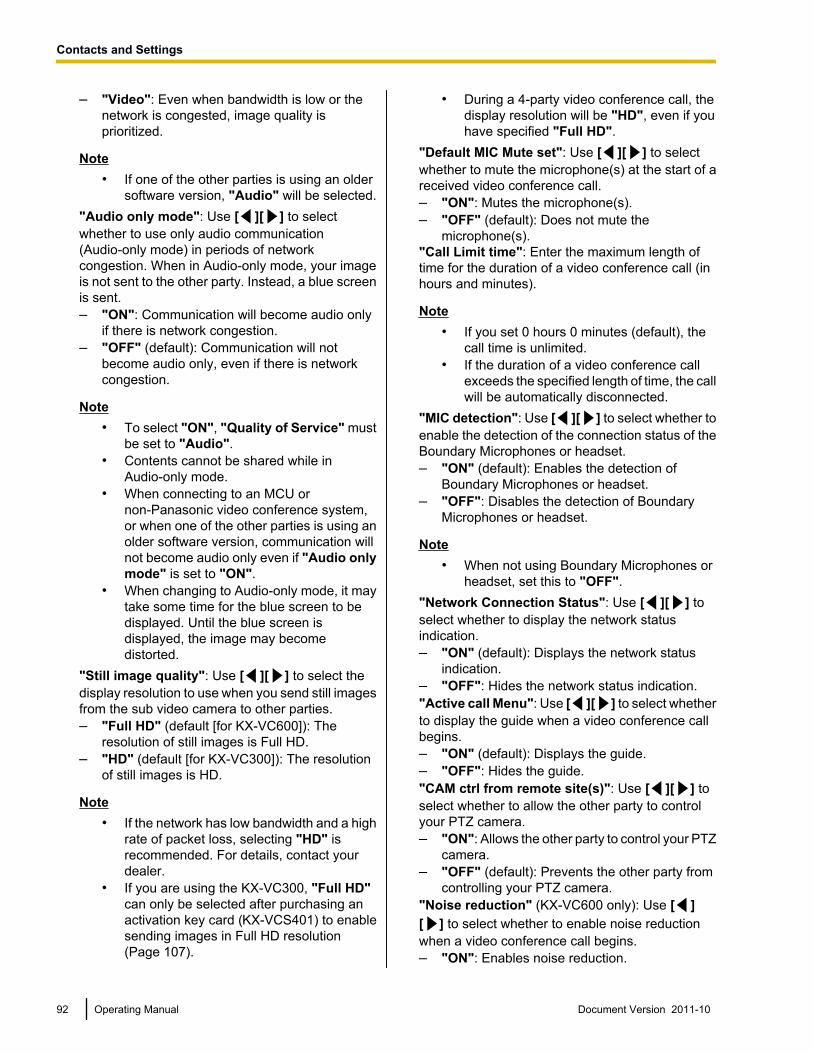
– "Video": Even when bandwidth is low or thenetwork is congested, image quality isprioritized.
Note• If one of the other parties is using an older
software version, "Audio" will be selected."Audio only mode": Use [ ][ ] to selectwhether to use only audio communication(Audio-only mode) in periods of networkcongestion. When in Audio-only mode, your imageis not sent to the other party. Instead, a blue screenis sent.– "ON": Communication will become audio only
if there is network congestion.– "OFF" (default): Communication will not
become audio only, even if there is networkcongestion.
Note• To select "ON", "Quality of Service" must
be set to "Audio".• Contents cannot be shared while in
Audio-only mode.• When connecting to an MCU or
non-Panasonic video conference system,or when one of the other parties is using anolder software version, communication willnot become audio only even if "Audio onlymode" is set to "ON".
• When changing to Audio-only mode, it maytake some time for the blue screen to bedisplayed. Until the blue screen isdisplayed, the image may becomedistorted.
"Still image quality": Use [ ][ ] to select thedisplay resolution to use when you send still imagesfrom the sub video camera to other parties.– "Full HD" (default [for KX-VC600]): The
resolution of still images is Full HD.– "HD" (default [for KX-VC300]): The resolution
of still images is HD.
Note• If the network has low bandwidth and a high
rate of packet loss, selecting "HD" isrecommended. For details, contact yourdealer.
• If you are using the KX-VC300, "Full HD"can only be selected after purchasing anactivation key card (KX-VCS401) to enablesending images in Full HD resolution(Page 107).
• During a 4-party video conference call, thedisplay resolution will be "HD", even if youhave specified "Full HD".
"Default MIC Mute set": Use [ ][ ] to selectwhether to mute the microphone(s) at the start of areceived video conference call.– "ON": Mutes the microphone(s).– "OFF" (default): Does not mute the
microphone(s)."Call Limit time": Enter the maximum length oftime for the duration of a video conference call (inhours and minutes).
Note• If you set 0 hours 0 minutes (default), the
call time is unlimited.• If the duration of a video conference call
exceeds the specified length of time, the callwill be automatically disconnected.
"MIC detection": Use [ ][ ] to select whether toenable the detection of the connection status of theBoundary Microphones or headset.– "ON" (default): Enables the detection of
Boundary Microphones or headset.– "OFF": Disables the detection of Boundary
Microphones or headset.
Note• When not using Boundary Microphones or
headset, set this to "OFF"."Network Connection Status": Use [ ][ ] toselect whether to display the network statusindication.– "ON" (default): Displays the network status
indication.– "OFF": Hides the network status indication."Active call Menu": Use [ ][ ] to select whetherto display the guide when a video conference callbegins.– "ON" (default): Displays the guide.– "OFF": Hides the guide."CAM ctrl from remote site(s)": Use [ ][ ] toselect whether to allow the other party to controlyour PTZ camera.– "ON": Allows the other party to control your PTZ
camera.– "OFF" (default): Prevents the other party from
controlling your PTZ camera."Noise reduction" (KX-VC600 only): Use [ ][ ] to select whether to enable noise reductionwhen a video conference call begins.– "ON": Enables noise reduction.
92 Operating Manual Document Version 2011-10
Contacts and Settings
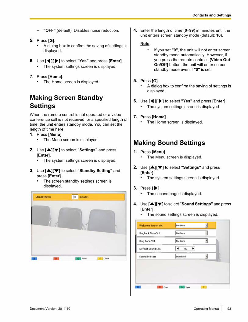
– "OFF" (default): Disables noise reduction.
5. Press [G].• A dialog box to confirm the saving of settings is
displayed.
6. Use [ ][ ] to select "Yes" and press [Enter].• The system settings screen is displayed.
7. Press [Home].• The Home screen is displayed.
Making Screen StandbySettingsWhen the remote control is not operated or a videoconference call is not received for a specified length oftime, the unit enters standby mode. You can set thelength of time here.1. Press [Menu].
• The Menu screen is displayed.
2. Use [ ][ ] to select "Settings" and press[Enter].• The system settings screen is displayed.
3. Use [ ][ ] to select "Standby Setting" andpress [Enter].• The screen standby settings screen is
displayed.
4. Enter the length of time (0–99) in minutes until theunit enters screen standby mode (default: 10).
Note• If you set "0", the unit will not enter screen
standby mode automatically. However, ifyou press the remote control’s [Video OutOn/Off] button, the unit will enter screenstandby mode even if "0" is set.
5. Press [G].• A dialog box to confirm the saving of settings is
displayed.
6. Use [ ][ ] to select "Yes" and press [Enter].• The system settings screen is displayed.
7. Press [Home].• The Home screen is displayed.
Making Sound Settings1. Press [Menu].
• The Menu screen is displayed.
2. Use [ ][ ] to select "Settings" and press[Enter].• The system settings screen is displayed.
3. Press [ ].• The second page is displayed.
4. Use [ ][ ] to select "Sound Settings" and press[Enter].• The sound settings screen is displayed.
Document Version 2011-10 Operating Manual 93
Contacts and Settings
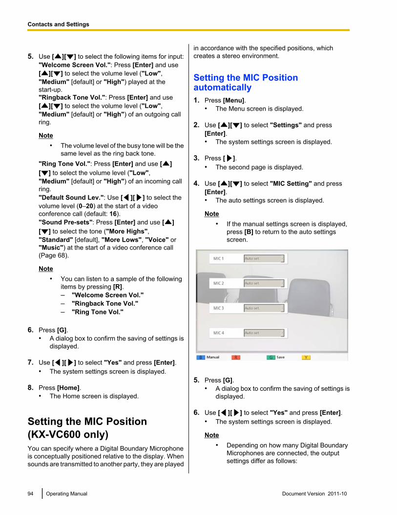
5. Use [ ][ ] to select the following items for input:"Welcome Screen Vol.": Press [Enter] and use[ ][ ] to select the volume level ("Low","Medium" [default] or "High") played at thestart-up."Ringback Tone Vol.": Press [Enter] and use[ ][ ] to select the volume level ("Low","Medium" [default] or "High") of an outgoing callring.
Note• The volume level of the busy tone will be the
same level as the ring back tone."Ring Tone Vol.": Press [Enter] and use [ ][ ] to select the volume level ("Low","Medium" [default] or "High") of an incoming callring."Default Sound Lev.": Use [ ][ ] to select thevolume level (0–20) at the start of a videoconference call (default: 16)."Sound Pre-sets": Press [Enter] and use [ ][ ] to select the tone ("More Highs","Standard" [default], "More Lows", "Voice" or"Music") at the start of a video conference call(Page 68).
Note• You can listen to a sample of the following
items by pressing [R].– "Welcome Screen Vol."– "Ringback Tone Vol."– "Ring Tone Vol."
6. Press [G].• A dialog box to confirm the saving of settings is
displayed.
7. Use [ ][ ] to select "Yes" and press [Enter].• The system settings screen is displayed.
8. Press [Home].• The Home screen is displayed.
Setting the MIC Position(KX-VC600 only)You can specify where a Digital Boundary Microphoneis conceptually positioned relative to the display. Whensounds are transmitted to another party, they are played
in accordance with the specified positions, whichcreates a stereo environment.
Setting the MIC Positionautomatically1. Press [Menu].
• The Menu screen is displayed.
2. Use [ ][ ] to select "Settings" and press[Enter].• The system settings screen is displayed.
3. Press [ ].• The second page is displayed.
4. Use [ ][ ] to select "MIC Setting" and press[Enter].• The auto settings screen is displayed.
Note• If the manual settings screen is displayed,
press [B] to return to the auto settingsscreen.
5. Press [G].• A dialog box to confirm the saving of settings is
displayed.
6. Use [ ][ ] to select "Yes" and press [Enter].• The system settings screen is displayed.
Note• Depending on how many Digital Boundary
Microphones are connected, the outputsettings differ as follows:
94 Operating Manual Document Version 2011-10
Contacts and Settings
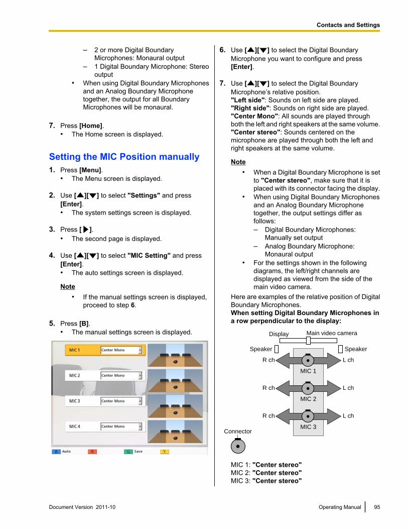
– 2 or more Digital BoundaryMicrophones: Monaural output
– 1 Digital Boundary Microphone: Stereooutput
• When using Digital Boundary Microphonesand an Analog Boundary Microphonetogether, the output for all BoundaryMicrophones will be monaural.
7. Press [Home].• The Home screen is displayed.
Setting the MIC Position manually1. Press [Menu].
• The Menu screen is displayed.
2. Use [ ][ ] to select "Settings" and press[Enter].• The system settings screen is displayed.
3. Press [ ].• The second page is displayed.
4. Use [ ][ ] to select "MIC Setting" and press[Enter].• The auto settings screen is displayed.
Note• If the manual settings screen is displayed,
proceed to step 6.
5. Press [B].• The manual settings screen is displayed.
6. Use [ ][ ] to select the Digital BoundaryMicrophone you want to configure and press[Enter].
7. Use [ ][ ] to select the Digital BoundaryMicrophone’s relative position."Left side": Sounds on left side are played."Right side": Sounds on right side are played."Center Mono": All sounds are played throughboth the left and right speakers at the same volume."Center stereo": Sounds centered on themicrophone are played through both the left andright speakers at the same volume.
Note• When a Digital Boundary Microphone is set
to "Center stereo", make sure that it isplaced with its connector facing the display.
• When using Digital Boundary Microphonesand an Analog Boundary Microphonetogether, the output settings differ asfollows:– Digital Boundary Microphones:
Manually set output– Analog Boundary Microphone:
Monaural output• For the settings shown in the following
diagrams, the left/right channels aredisplayed as viewed from the side of themain video camera.
Here are examples of the relative position of DigitalBoundary Microphones.When setting Digital Boundary Microphones ina row perpendicular to the display:
Connector
Main video camera
Speaker Speaker
Display
R ch L ch
MIC 1
R ch L ch
MIC 2
R ch L ch
MIC 3
MIC 1: "Center stereo"MIC 2: "Center stereo"MIC 3: "Center stereo"
Document Version 2011-10 Operating Manual 95
Contacts and Settings
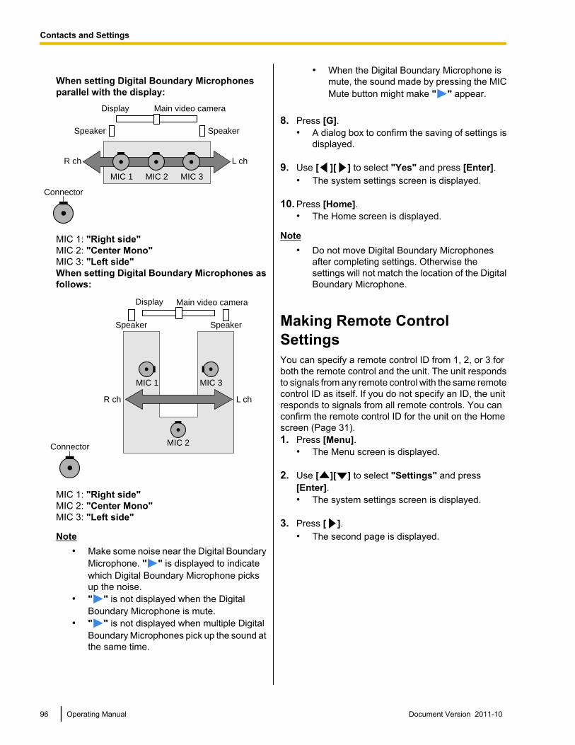
When setting Digital Boundary Microphonesparallel with the display:
Connector
Main video camera
Speaker Speaker
Display
R ch L ch
MIC 1 MIC 2 MIC 3
MIC 1: "Right side"MIC 2: "Center Mono"MIC 3: "Left side"When setting Digital Boundary Microphones asfollows:
Main video camera
R ch L ch
MIC 2
MIC 3MIC 1
Display
Speaker Speaker
Connector
MIC 1: "Right side"MIC 2: "Center Mono"MIC 3: "Left side"
Note• Make some noise near the Digital Boundary
Microphone. " " is displayed to indicatewhich Digital Boundary Microphone picksup the noise.
• " " is not displayed when the DigitalBoundary Microphone is mute.
• " " is not displayed when multiple DigitalBoundary Microphones pick up the sound atthe same time.
• When the Digital Boundary Microphone ismute, the sound made by pressing the MICMute button might make " " appear.
8. Press [G].• A dialog box to confirm the saving of settings is
displayed.
9. Use [ ][ ] to select "Yes" and press [Enter].• The system settings screen is displayed.
10. Press [Home].• The Home screen is displayed.
Note• Do not move Digital Boundary Microphones
after completing settings. Otherwise thesettings will not match the location of the DigitalBoundary Microphone.
Making Remote ControlSettingsYou can specify a remote control ID from 1, 2, or 3 forboth the remote control and the unit. The unit respondsto signals from any remote control with the same remotecontrol ID as itself. If you do not specify an ID, the unitresponds to signals from all remote controls. You canconfirm the remote control ID for the unit on the Homescreen (Page 31).1. Press [Menu].
• The Menu screen is displayed.
2. Use [ ][ ] to select "Settings" and press[Enter].• The system settings screen is displayed.
3. Press [ ].• The second page is displayed.
96 Operating Manual Document Version 2011-10
Contacts and Settings
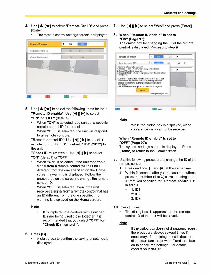
4. Use [ ][ ] to select "Remote Ctrl ID" and press[Enter].• The remote control settings screen is displayed.
5. Use [ ][ ] to select the following items for input:"Remote ID enable": Use [ ][ ] to select"ON" or "OFF" (default).• When "ON" is selected, you can set a specific
remote control ID for the unit.• When "OFF" is selected, the unit will respond
to all remote controls."Remote control ID": Use [ ][ ] to select aremote control ID ("ID1" [default]/"ID2"/"ID3") forthe unit."Check ID mismatch": Use [ ][ ] to select"ON" (default) or "OFF".• When "ON" is selected, if the unit receives a
signal from a remote control that has an IDdifferent from the one specified on the Homescreen, a warning is displayed. Follow theprocedures on the screen to change the remotecontrol ID.
• When "OFF" is selected, even if the unitreceives a signal from a remote control that hasan ID different from the one specified, nowarning is displayed on the Home screen.
Note• If multiple remote controls with assigned
IDs are being used close together, it isrecommended that you select "OFF" for"Check ID mismatch".
6. Press [G].• A dialog box to confirm the saving of settings is
displayed.
7. Use [ ][ ] to select "Yes" and press [Enter].
8. When "Remote ID enable" is set to"ON" (Page 97):The dialog box for changing the ID of the remotecontrol is displayed. Proceed to step 9.
Note• While the dialog box is displayed, video
conference calls cannot be received.
When "Remote ID enable" is set to"OFF" (Page 97):The system settings screen is displayed. Press[Home] to return to the Home screen.
9. Use the following procedure to change the ID of theremote control.1. Press and hold [·] and [#] at the same time.2. Within 2 seconds after you release the buttons,
press the number (1 to 3) corresponding to theID that you specified for "Remote control ID"in step 4.– 1: ID1– 2: ID2– 3: ID3
10. Press [Enter].• The dialog box disappears and the remote
control ID of the unit will be saved.
Note• If the dialog box does not disappear, repeat
the procedure above, several times ifnecessary. If the dialog box still does notdisappear, turn the power off and then backon to cancel the settings. For details,contact your dealer.
Document Version 2011-10 Operating Manual 97
Contacts and Settings
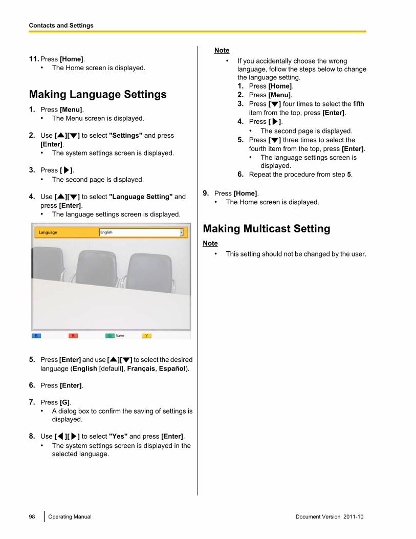
11. Press [Home].• The Home screen is displayed.
Making Language Settings1. Press [Menu].
• The Menu screen is displayed.
2. Use [ ][ ] to select "Settings" and press[Enter].• The system settings screen is displayed.
3. Press [ ].• The second page is displayed.
4. Use [ ][ ] to select "Language Setting" andpress [Enter].• The language settings screen is displayed.
5. Press [Enter] and use [ ][ ] to select the desiredlanguage (English [default], Français, Español).
6. Press [Enter].
7. Press [G].• A dialog box to confirm the saving of settings is
displayed.
8. Use [ ][ ] to select "Yes" and press [Enter].• The system settings screen is displayed in the
selected language.
Note• If you accidentally choose the wrong
language, follow the steps below to changethe language setting.1. Press [Home].2. Press [Menu].3. Press [ ] four times to select the fifth
item from the top, press [Enter].4. Press [ ].
• The second page is displayed.5. Press [ ] three times to select the
fourth item from the top, press [Enter].• The language settings screen is
displayed.6. Repeat the procedure from step 5.
9. Press [Home].• The Home screen is displayed.
Making Multicast SettingNote
• This setting should not be changed by the user.
98 Operating Manual Document Version 2011-10
Contacts and Settings
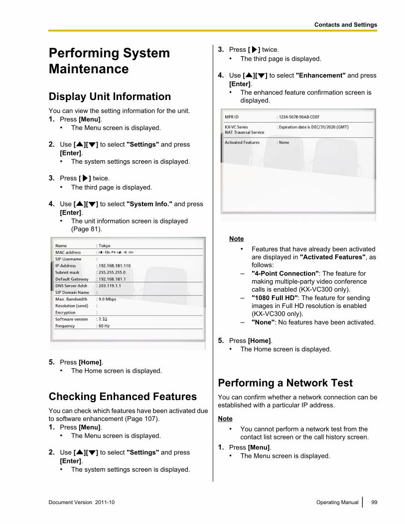
Performing SystemMaintenance
Display Unit InformationYou can view the setting information for the unit.1. Press [Menu].
• The Menu screen is displayed.
2. Use [ ][ ] to select "Settings" and press[Enter].• The system settings screen is displayed.
3. Press [ ] twice.• The third page is displayed.
4. Use [ ][ ] to select "System Info." and press[Enter].• The unit information screen is displayed
(Page 81).
5. Press [Home].• The Home screen is displayed.
Checking Enhanced FeaturesYou can check which features have been activated dueto software enhancement (Page 107).1. Press [Menu].
• The Menu screen is displayed.
2. Use [ ][ ] to select "Settings" and press[Enter].• The system settings screen is displayed.
3. Press [ ] twice.• The third page is displayed.
4. Use [ ][ ] to select "Enhancement" and press[Enter].• The enhanced feature confirmation screen is
displayed.
Note• Features that have already been activated
are displayed in "Activated Features", asfollows:
– "4-Point Connection": The feature formaking multiple-party video conferencecalls is enabled (KX-VC300 only).
– "1080 Full HD": The feature for sendingimages in Full HD resolution is enabled(KX-VC300 only).
– "None": No features have been activated.
5. Press [Home].• The Home screen is displayed.
Performing a Network TestYou can confirm whether a network connection can beestablished with a particular IP address.
Note• You cannot perform a network test from the
contact list screen or the call history screen.1. Press [Menu].
• The Menu screen is displayed.
Document Version 2011-10 Operating Manual 99
Contacts and Settings
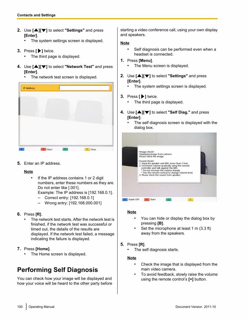
2. Use [ ][ ] to select "Settings" and press[Enter].• The system settings screen is displayed.
3. Press [ ] twice.• The third page is displayed.
4. Use [ ][ ] to select "Network Test" and press[Enter].• The network test screen is displayed.
5. Enter an IP address.
Note• If the IP address contains 1 or 2 digit
numbers, enter these numbers as they are.Do not enter like [.001].Example: The IP address is [192.168.0.1].– Correct entry: [192.168.0.1]– Wrong entry: [192.168.000.001]
6. Press [R].• The network test starts. After the network test is
finished, if the network test was successful ortimed out, the details of the results aredisplayed. If the network test failed, a messageindicating the failure is displayed.
7. Press [Home].• The Home screen is displayed.
Performing Self DiagnosisYou can check how your image will be displayed andhow your voice will be heard to the other party before
starting a video conference call, using your own displayand speakers.
Note• Self diagnosis can be performed even when a
headset is connected.1. Press [Menu].
• The Menu screen is displayed.
2. Use [ ][ ] to select "Settings" and press[Enter].• The system settings screen is displayed.
3. Press [ ] twice.• The third page is displayed.
4. Use [ ][ ] to select "Self Diag." and press[Enter].• The self diagnosis screen is displayed with the
dialog box.
Note• You can hide or display the dialog box by
pressing [B].• Set the microphone at least 1 m (3.3 ft)
away from the speakers.
5. Press [R].• The self diagnosis starts.
Note• Check the image that is displayed from the
main video camera.• To avoid feedback, slowly raise the volume
using the remote control’s [+] button.
100 Operating Manual Document Version 2011-10
Contacts and Settings
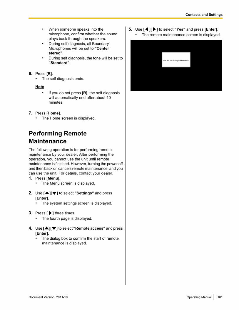
• When someone speaks into themicrophone, confirm whether the soundplays back through the speakers.
• During self diagnosis, all BoundaryMicrophones will be set to "Centerstereo".
• During self diagnosis, the tone will be set to"Standard".
6. Press [R].• The self diagnosis ends.
Note• If you do not press [R], the self diagnosis
will automatically end after about 10minutes.
7. Press [Home].• The Home screen is displayed.
Performing RemoteMaintenanceThe following operation is for performing remotemaintenance by your dealer. After performing theoperation, you cannot use the unit until remotemaintenance is finished. However, turning the power offand then back on cancels remote maintenance, and youcan use the unit. For details, contact your dealer.1. Press [Menu].
• The Menu screen is displayed.
2. Use [ ][ ] to select "Settings" and press[Enter].• The system settings screen is displayed.
3. Press [ ] three times.• The fourth page is displayed.
4. Use [ ][ ] to select "Remote access" and press[Enter].• The dialog box to confirm the start of remote
maintenance is displayed.
5. Use [ ][ ] to select "Yes" and press [Enter].• The remote maintenance screen is displayed.
Document Version 2011-10 Operating Manual 101
Contacts and Settings
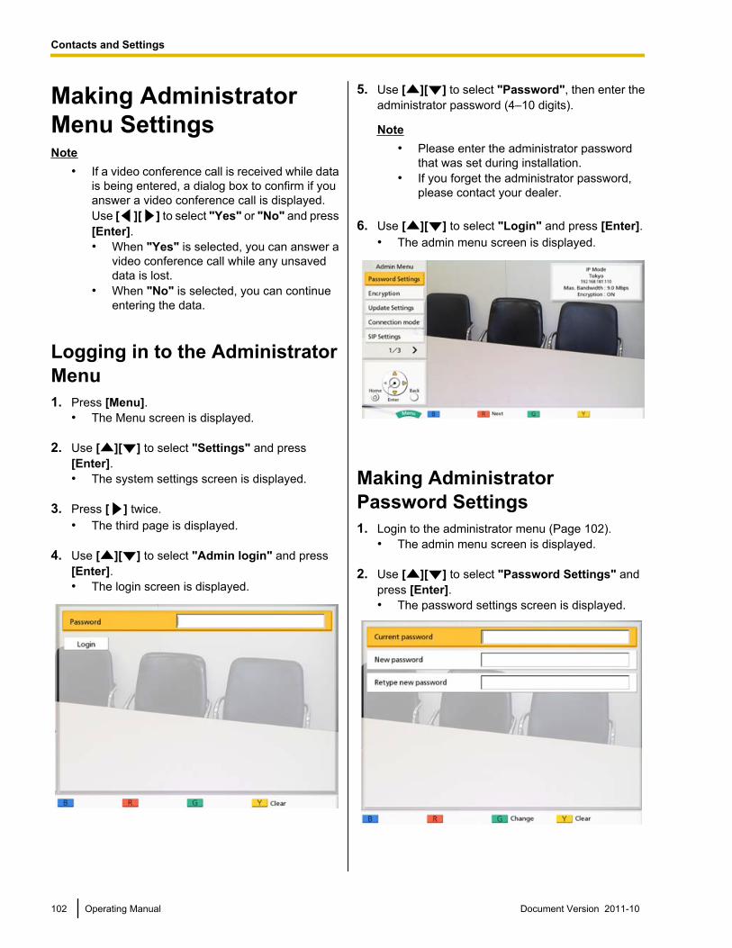
Making AdministratorMenu SettingsNote
• If a video conference call is received while datais being entered, a dialog box to confirm if youanswer a video conference call is displayed.Use [ ][ ] to select "Yes" or "No" and press[Enter].• When "Yes" is selected, you can answer a
video conference call while any unsaveddata is lost.
• When "No" is selected, you can continueentering the data.
Logging in to the AdministratorMenu1. Press [Menu].
• The Menu screen is displayed.
2. Use [ ][ ] to select "Settings" and press[Enter].• The system settings screen is displayed.
3. Press [ ] twice.• The third page is displayed.
4. Use [ ][ ] to select "Admin login" and press[Enter].• The login screen is displayed.
5. Use [ ][ ] to select "Password", then enter theadministrator password (4–10 digits).
Note• Please enter the administrator password
that was set during installation.• If you forget the administrator password,
please contact your dealer.
6. Use [ ][ ] to select "Login" and press [Enter].• The admin menu screen is displayed.
Making AdministratorPassword Settings1. Login to the administrator menu (Page 102).
• The admin menu screen is displayed.
2. Use [ ][ ] to select "Password Settings" andpress [Enter].• The password settings screen is displayed.
102 Operating Manual Document Version 2011-10
Contacts and Settings
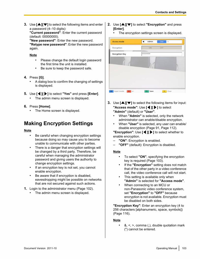
3. Use [ ][ ] to select the following items and entera password (4–10 digits):"Current password": Enter the current password(default: 00000000)."New password": Enter the new password."Retype new password": Enter the new passwordagain.
Note• Please change the default login password
the first time the unit is installed.• Be sure to keep the password safe.
4. Press [G].• A dialog box to confirm the changing of settings
is displayed.
5. Use [ ][ ] to select "Yes" and press [Enter].• The admin menu screen is displayed.
6. Press [Home].• The Home screen is displayed.
Making Encryption SettingsNote
• Be careful when changing encryption settingsbecause doing so may cause you to becomeunable to communicate with other parties.
• There is a danger that encryption settings willbe changed by a third party. Therefore, becareful when managing the administratorpassword and giving users the authority tochange encryption settings.
• If an encryption key is not set, you cannotenable encryption.
• Be aware that if encryption is disabled,eavesdropping might be possible on networksthat are not secured against such actions.
1. Login to the administrator menu (Page 102).• The admin menu screen is displayed.
2. Use [ ][ ] to select "Encryption" and press[Enter].• The encryption settings screen is displayed.
3. Use [ ][ ] to select the following items for input:"Access mode": Use [ ][ ] to select"Admin" (default) or "User".• When "Admin" is selected, only the network
administrator can enable/disable encryption.• When "User" is selected, any user can enable/
disable encryption (Page 91, Page 112)."Encryption": Use [ ][ ] to select whether toenable encryption.– "ON": Encryption is enabled.– "OFF" (default): Encryption is disabled.
Note• To select "ON", specifying the encryption
key is required (Page 103).• If the "Encryption" setting does not match
that of the other party in a video conferencecall, the video conference call will not start.
• This setting is available only when"Admin" is selected for "Access mode".
• When connecting to an MCU ornon-Panasonic video conference system,set "Encryption" to "OFF" becauseencryption is not available. Encryption mustbe disabled on both sides.
"Encryption Key": Enter an encryption key (4 to256 characters [alphanumeric, space, symbols])(Page 116).
Note• &, <, >, comma (,), double quotation mark
(") cannot be entered.
Document Version 2011-10 Operating Manual 103
Contacts and Settings
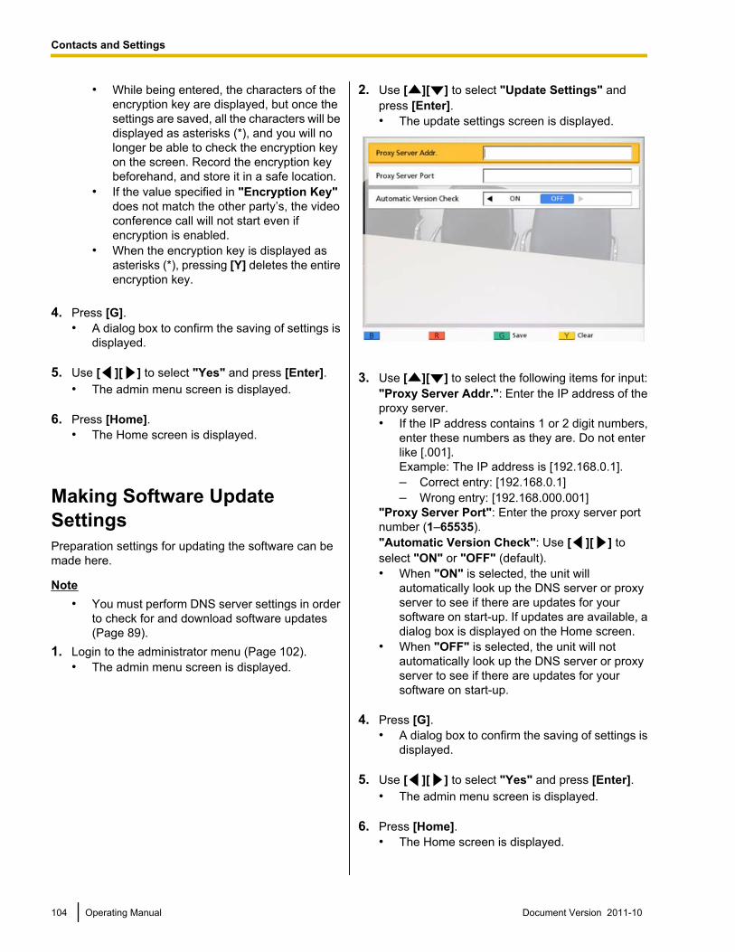
• While being entered, the characters of theencryption key are displayed, but once thesettings are saved, all the characters will bedisplayed as asterisks (*), and you will nolonger be able to check the encryption keyon the screen. Record the encryption keybeforehand, and store it in a safe location.
• If the value specified in "Encryption Key"does not match the other party’s, the videoconference call will not start even ifencryption is enabled.
• When the encryption key is displayed asasterisks (*), pressing [Y] deletes the entireencryption key.
4. Press [G].• A dialog box to confirm the saving of settings is
displayed.
5. Use [ ][ ] to select "Yes" and press [Enter].• The admin menu screen is displayed.
6. Press [Home].• The Home screen is displayed.
Making Software UpdateSettingsPreparation settings for updating the software can bemade here.
Note• You must perform DNS server settings in order
to check for and download software updates(Page 89).
1. Login to the administrator menu (Page 102).• The admin menu screen is displayed.
2. Use [ ][ ] to select "Update Settings" andpress [Enter].• The update settings screen is displayed.
3. Use [ ][ ] to select the following items for input:"Proxy Server Addr.": Enter the IP address of theproxy server.• If the IP address contains 1 or 2 digit numbers,
enter these numbers as they are. Do not enterlike [.001].Example: The IP address is [192.168.0.1].– Correct entry: [192.168.0.1]– Wrong entry: [192.168.000.001]
"Proxy Server Port": Enter the proxy server portnumber (1–65535)."Automatic Version Check": Use [ ][ ] toselect "ON" or "OFF" (default).• When "ON" is selected, the unit will
automatically look up the DNS server or proxyserver to see if there are updates for yoursoftware on start-up. If updates are available, adialog box is displayed on the Home screen.
• When "OFF" is selected, the unit will notautomatically look up the DNS server or proxyserver to see if there are updates for yoursoftware on start-up.
4. Press [G].• A dialog box to confirm the saving of settings is
displayed.
5. Use [ ][ ] to select "Yes" and press [Enter].• The admin menu screen is displayed.
6. Press [Home].• The Home screen is displayed.
104 Operating Manual Document Version 2011-10
Contacts and Settings
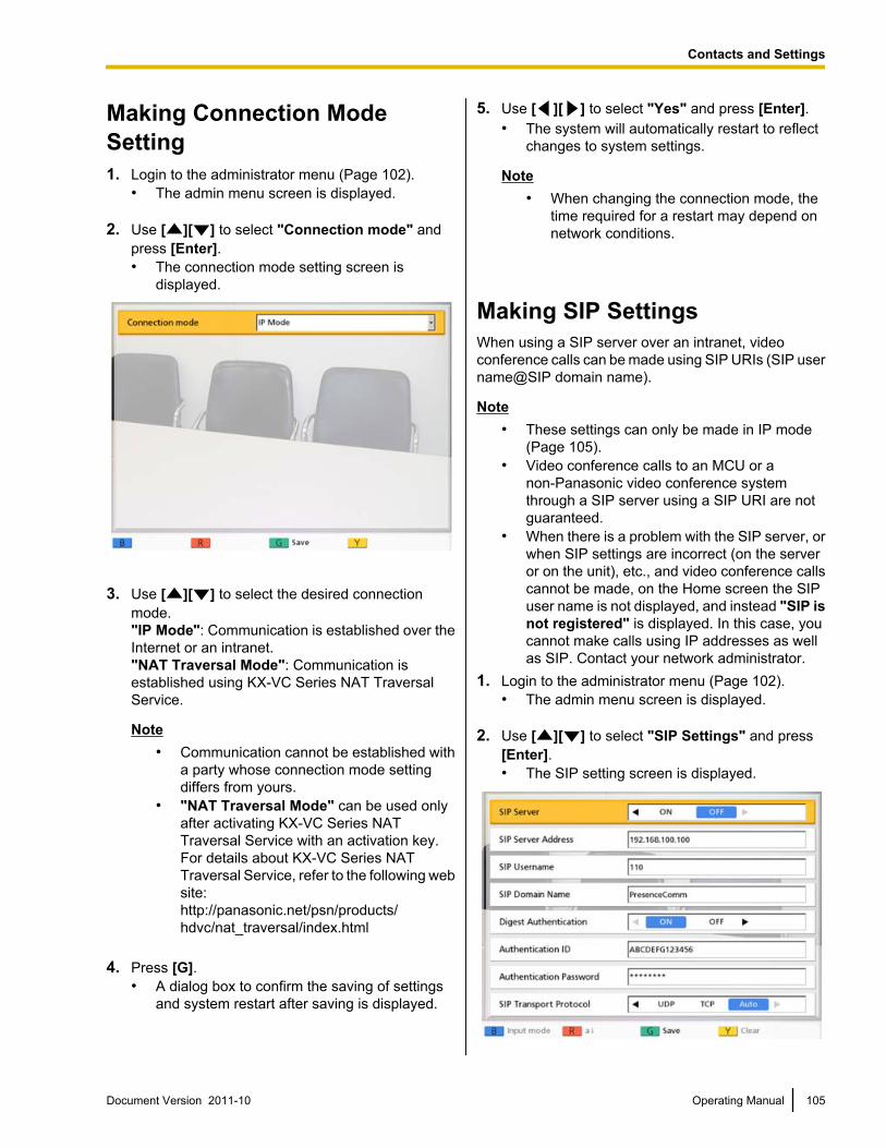
Making Connection ModeSetting1. Login to the administrator menu (Page 102).
• The admin menu screen is displayed.
2. Use [ ][ ] to select "Connection mode" andpress [Enter].• The connection mode setting screen is
displayed.
3. Use [ ][ ] to select the desired connectionmode."IP Mode": Communication is established over theInternet or an intranet."NAT Traversal Mode": Communication isestablished using KX-VC Series NAT TraversalService.
Note• Communication cannot be established with
a party whose connection mode settingdiffers from yours.
• "NAT Traversal Mode" can be used onlyafter activating KX-VC Series NATTraversal Service with an activation key.For details about KX-VC Series NATTraversal Service, refer to the following website:http://panasonic.net/psn/products/hdvc/nat_traversal/index.html
4. Press [G].• A dialog box to confirm the saving of settings
and system restart after saving is displayed.
5. Use [ ][ ] to select "Yes" and press [Enter].• The system will automatically restart to reflect
changes to system settings.
Note• When changing the connection mode, the
time required for a restart may depend onnetwork conditions.
Making SIP SettingsWhen using a SIP server over an intranet, videoconference calls can be made using SIP URIs (SIP username@SIP domain name).
Note• These settings can only be made in IP mode
(Page 105).• Video conference calls to an MCU or a
non-Panasonic video conference systemthrough a SIP server using a SIP URI are notguaranteed.
• When there is a problem with the SIP server, orwhen SIP settings are incorrect (on the serveror on the unit), etc., and video conference callscannot be made, on the Home screen the SIPuser name is not displayed, and instead "SIP isnot registered" is displayed. In this case, youcannot make calls using IP addresses as wellas SIP. Contact your network administrator.
1. Login to the administrator menu (Page 102).• The admin menu screen is displayed.
2. Use [ ][ ] to select "SIP Settings" and press[Enter].• The SIP setting screen is displayed.
Document Version 2011-10 Operating Manual 105
Contacts and Settings
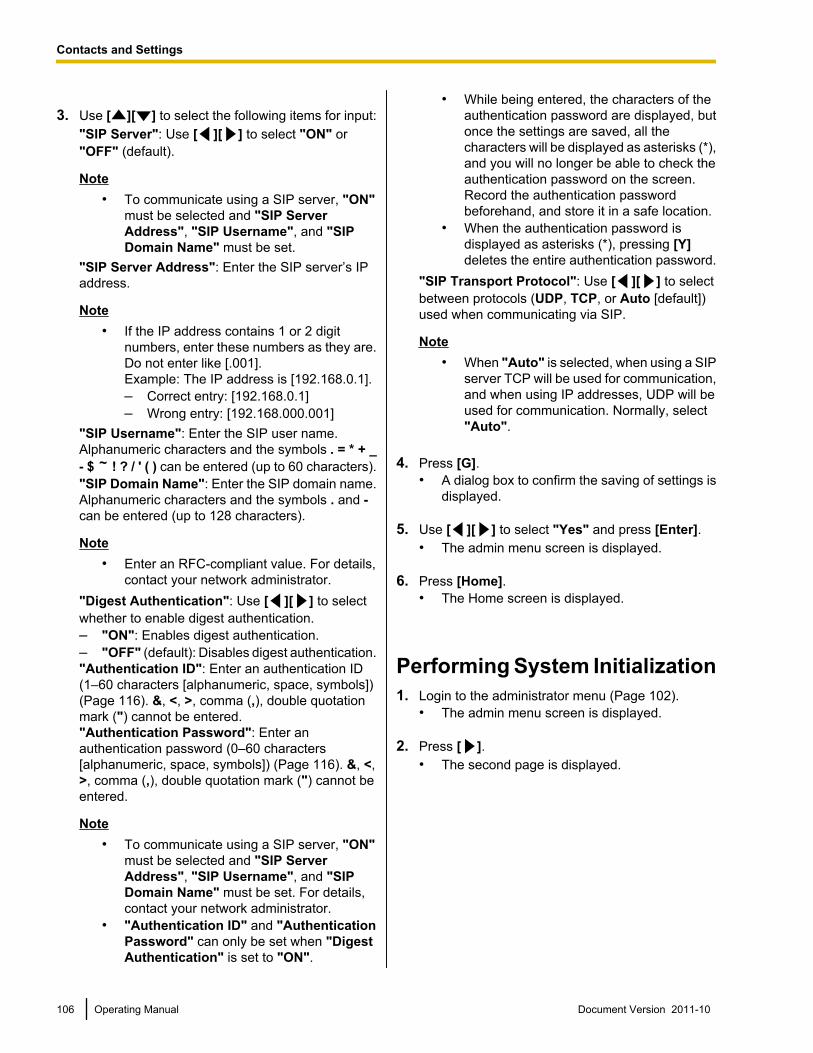
3. Use [ ][ ] to select the following items for input:"SIP Server": Use [ ][ ] to select "ON" or"OFF" (default).
Note• To communicate using a SIP server, "ON"
must be selected and "SIP ServerAddress", "SIP Username", and "SIPDomain Name" must be set.
"SIP Server Address": Enter the SIP server’s IPaddress.
Note• If the IP address contains 1 or 2 digit
numbers, enter these numbers as they are.Do not enter like [.001].Example: The IP address is [192.168.0.1].– Correct entry: [192.168.0.1]– Wrong entry: [192.168.000.001]
"SIP Username": Enter the SIP user name.Alphanumeric characters and the symbols . = * + _- $ ! ? / ' ( ) can be entered (up to 60 characters)."SIP Domain Name": Enter the SIP domain name.Alphanumeric characters and the symbols . and -can be entered (up to 128 characters).
Note• Enter an RFC-compliant value. For details,
contact your network administrator."Digest Authentication": Use [ ][ ] to selectwhether to enable digest authentication.– "ON": Enables digest authentication.– "OFF" (default): Disables digest authentication."Authentication ID": Enter an authentication ID(1–60 characters [alphanumeric, space, symbols])(Page 116). &, <, >, comma (,), double quotationmark (") cannot be entered."Authentication Password": Enter anauthentication password (0–60 characters[alphanumeric, space, symbols]) (Page 116). &, <,>, comma (,), double quotation mark (") cannot beentered.
Note• To communicate using a SIP server, "ON"
must be selected and "SIP ServerAddress", "SIP Username", and "SIPDomain Name" must be set. For details,contact your network administrator.
• "Authentication ID" and "AuthenticationPassword" can only be set when "DigestAuthentication" is set to "ON".
• While being entered, the characters of theauthentication password are displayed, butonce the settings are saved, all thecharacters will be displayed as asterisks (*),and you will no longer be able to check theauthentication password on the screen.Record the authentication passwordbeforehand, and store it in a safe location.
• When the authentication password isdisplayed as asterisks (*), pressing [Y]deletes the entire authentication password.
"SIP Transport Protocol": Use [ ][ ] to selectbetween protocols (UDP, TCP, or Auto [default])used when communicating via SIP.
Note• When "Auto" is selected, when using a SIP
server TCP will be used for communication,and when using IP addresses, UDP will beused for communication. Normally, select"Auto".
4. Press [G].• A dialog box to confirm the saving of settings is
displayed.
5. Use [ ][ ] to select "Yes" and press [Enter].• The admin menu screen is displayed.
6. Press [Home].• The Home screen is displayed.
Performing System Initialization1. Login to the administrator menu (Page 102).
• The admin menu screen is displayed.
2. Press [ ].• The second page is displayed.
106 Operating Manual Document Version 2011-10
Contacts and Settings
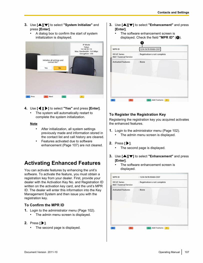
3. Use [ ][ ] to select "System Initialize" andpress [Enter].• A dialog box to confirm the start of system
initialization is displayed.
4. Use [ ][ ] to select "Yes" and press [Enter].• The system will automatically restart to
complete the system initialization.
Note• After initialization, all system settings
previously made and information stored inthe contact list and call history are cleared.
• Features activated due to softwareenhancement (Page 107) are not cleared.
Activating Enhanced FeaturesYou can activate features by enhancing the unit’ssoftware. To activate the feature, you must obtain aregistration key from your dealer. First, provide yourdealer with the Activation Key No. and Registration IDwritten on the activation key card, and the unit’s MPRID. The dealer will enter this information into the KeyManagement System and then issue you with theregistration key.
To Confirm the MPR ID1. Login to the administrator menu (Page 102).
• The admin menu screen is displayed.
2. Press [ ].• The second page is displayed.
3. Use [ ][ ] to select "Enhancement" and press[Enter].• The software enhancement screen is
displayed. Check the field "MPR ID" (A).A
To Register the Registration KeyRegistering the registration key you acquired activatesthe enhanced features.
1. Login to the administrator menu (Page 102).• The admin menu screen is displayed.
2. Press [ ].• The second page is displayed.
3. Use [ ][ ] to select "Enhancement" and press[Enter].• The software enhancement screen is
displayed.
Document Version 2011-10 Operating Manual 107
Contacts and Settings
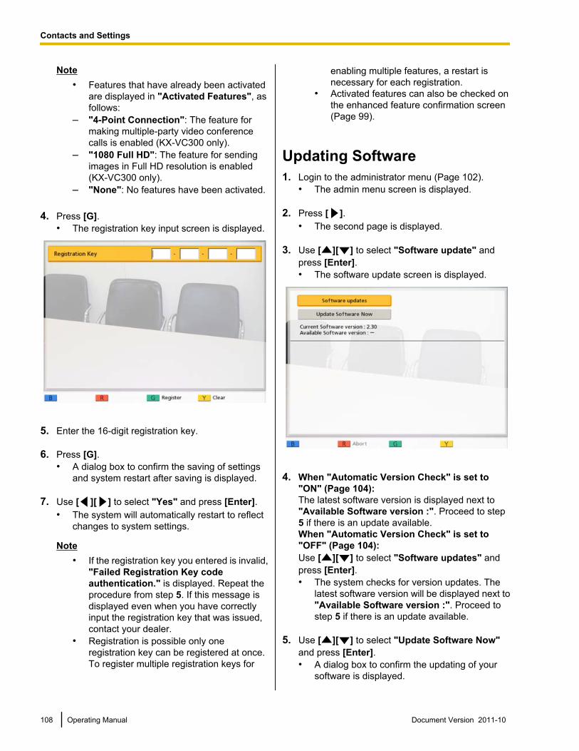
Note• Features that have already been activated
are displayed in "Activated Features", asfollows:
– "4-Point Connection": The feature formaking multiple-party video conferencecalls is enabled (KX-VC300 only).
– "1080 Full HD": The feature for sendingimages in Full HD resolution is enabled(KX-VC300 only).
– "None": No features have been activated.
4. Press [G].• The registration key input screen is displayed.
5. Enter the 16-digit registration key.
6. Press [G].• A dialog box to confirm the saving of settings
and system restart after saving is displayed.
7. Use [ ][ ] to select "Yes" and press [Enter].• The system will automatically restart to reflect
changes to system settings.
Note• If the registration key you entered is invalid,
"Failed Registration Key codeauthentication." is displayed. Repeat theprocedure from step 5. If this message isdisplayed even when you have correctlyinput the registration key that was issued,contact your dealer.
• Registration is possible only oneregistration key can be registered at once.To register multiple registration keys for
enabling multiple features, a restart isnecessary for each registration.
• Activated features can also be checked onthe enhanced feature confirmation screen(Page 99).
Updating Software1. Login to the administrator menu (Page 102).
• The admin menu screen is displayed.
2. Press [ ].• The second page is displayed.
3. Use [ ][ ] to select "Software update" andpress [Enter].• The software update screen is displayed.
4. When "Automatic Version Check" is set to"ON" (Page 104):The latest software version is displayed next to"Available Software version :". Proceed to step5 if there is an update available.When "Automatic Version Check" is set to"OFF" (Page 104):Use [ ][ ] to select "Software updates" andpress [Enter].• The system checks for version updates. The
latest software version will be displayed next to"Available Software version :". Proceed tostep 5 if there is an update available.
5. Use [ ][ ] to select "Update Software Now"and press [Enter].• A dialog box to confirm the updating of your
software is displayed.
108 Operating Manual Document Version 2011-10
Contacts and Settings
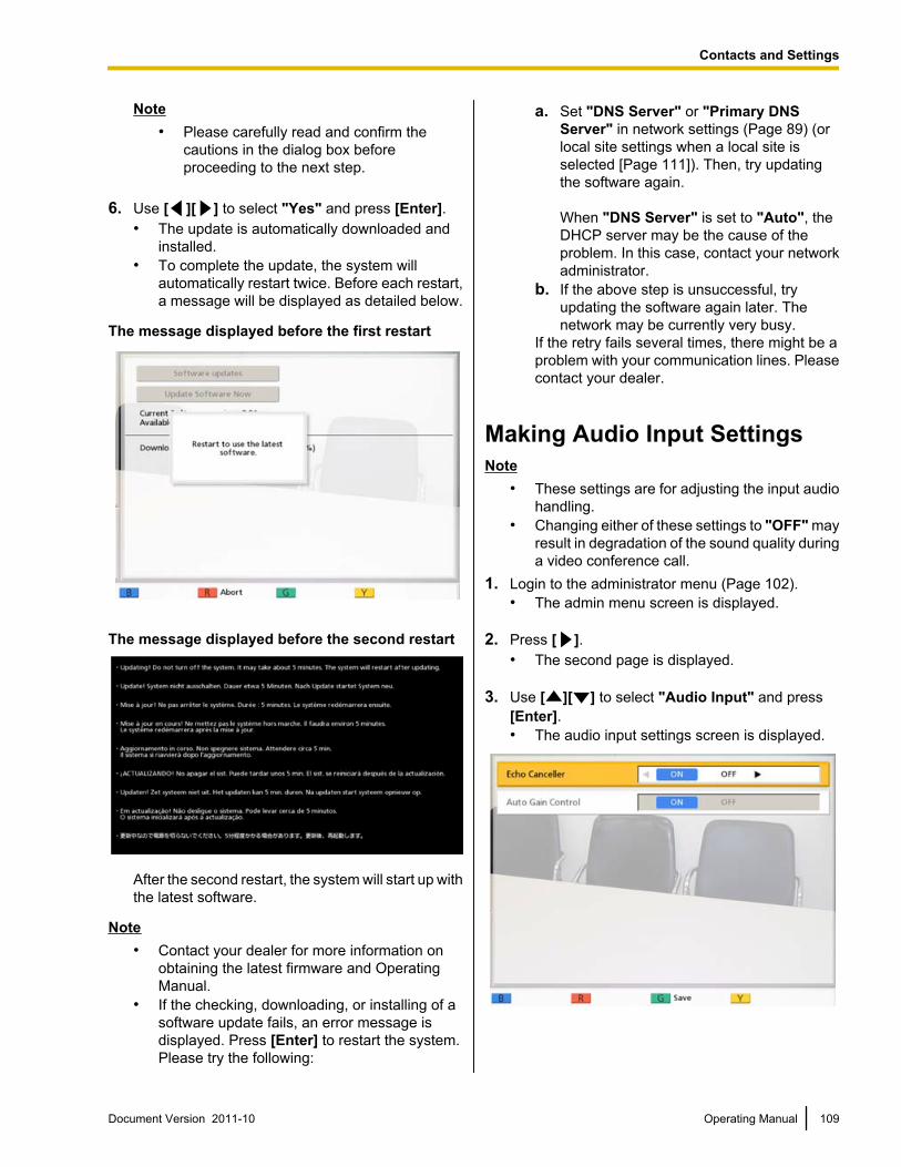
Note• Please carefully read and confirm the
cautions in the dialog box beforeproceeding to the next step.
6. Use [ ][ ] to select "Yes" and press [Enter].• The update is automatically downloaded and
installed.• To complete the update, the system will
automatically restart twice. Before each restart,a message will be displayed as detailed below.
The message displayed before the first restart
The message displayed before the second restart
After the second restart, the system will start up withthe latest software.
Note• Contact your dealer for more information on
obtaining the latest firmware and OperatingManual.
• If the checking, downloading, or installing of asoftware update fails, an error message isdisplayed. Press [Enter] to restart the system.Please try the following:
a. Set "DNS Server" or "Primary DNSServer" in network settings (Page 89) (orlocal site settings when a local site isselected [Page 111]). Then, try updatingthe software again.
When "DNS Server" is set to "Auto", theDHCP server may be the cause of theproblem. In this case, contact your networkadministrator.
b. If the above step is unsuccessful, tryupdating the software again later. Thenetwork may be currently very busy.
If the retry fails several times, there might be aproblem with your communication lines. Pleasecontact your dealer.
Making Audio Input SettingsNote
• These settings are for adjusting the input audiohandling.
• Changing either of these settings to "OFF" mayresult in degradation of the sound quality duringa video conference call.
1. Login to the administrator menu (Page 102).• The admin menu screen is displayed.
2. Press [ ].• The second page is displayed.
3. Use [ ][ ] to select "Audio Input" and press[Enter].• The audio input settings screen is displayed.
Document Version 2011-10 Operating Manual 109
Contacts and Settings
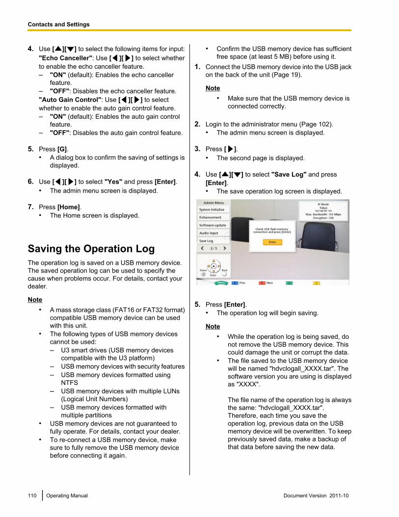
4. Use [ ][ ] to select the following items for input:"Echo Canceller": Use [ ][ ] to select whetherto enable the echo canceller feature.– "ON" (default): Enables the echo canceller
feature.– "OFF": Disables the echo canceller feature."Auto Gain Control": Use [ ][ ] to selectwhether to enable the auto gain control feature.– "ON" (default): Enables the auto gain control
feature.– "OFF": Disables the auto gain control feature.
5. Press [G].• A dialog box to confirm the saving of settings is
displayed.
6. Use [ ][ ] to select "Yes" and press [Enter].• The admin menu screen is displayed.
7. Press [Home].• The Home screen is displayed.
Saving the Operation LogThe operation log is saved on a USB memory device.The saved operation log can be used to specify thecause when problems occur. For details, contact yourdealer.
Note• A mass storage class (FAT16 or FAT32 format)
compatible USB memory device can be usedwith this unit.
• The following types of USB memory devicescannot be used:– U3 smart drives (USB memory devices
compatible with the U3 platform)– USB memory devices with security features– USB memory devices formatted using
NTFS– USB memory devices with multiple LUNs
(Logical Unit Numbers)– USB memory devices formatted with
multiple partitions• USB memory devices are not guaranteed to
fully operate. For details, contact your dealer.• To re-connect a USB memory device, make
sure to fully remove the USB memory devicebefore connecting it again.
• Confirm the USB memory device has sufficientfree space (at least 5 MB) before using it.
1. Connect the USB memory device into the USB jackon the back of the unit (Page 19).
Note• Make sure that the USB memory device is
connected correctly.
2. Login to the administrator menu (Page 102).• The admin menu screen is displayed.
3. Press [ ].• The second page is displayed.
4. Use [ ][ ] to select "Save Log" and press[Enter].• The save operation log screen is displayed.
5. Press [Enter].• The operation log will begin saving.
Note• While the operation log is being saved, do
not remove the USB memory device. Thiscould damage the unit or corrupt the data.
• The file saved to the USB memory devicewill be named "hdvclogall_XXXX.tar". Thesoftware version you are using is displayedas "XXXX".
The file name of the operation log is alwaysthe same: "hdvclogall_XXXX.tar".Therefore, each time you save theoperation log, previous data on the USBmemory device will be overwritten. To keeppreviously saved data, make a backup ofthat data before saving the new data.
110 Operating Manual Document Version 2011-10
Contacts and Settings
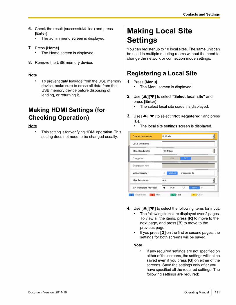
6. Check the result (successful/failed) and press[Enter].• The admin menu screen is displayed.
7. Press [Home].• The Home screen is displayed.
8. Remove the USB memory device.
Note• To prevent data leakage from the USB memory
device, make sure to erase all data from theUSB memory device before disposing of,lending, or returning it.
Making HDMI Settings (forChecking Operation)Note
• This setting is for verifying HDMI operation. Thissetting does not need to be changed usually.
Making Local SiteSettingsYou can register up to 10 local sites. The same unit canbe used in multiple meeting rooms without the need tochange the network or connection mode settings.
Registering a Local Site1. Press [Menu].
• The Menu screen is displayed.
2. Use [ ][ ] to select "Select local site" andpress [Enter].• The select local site screen is displayed.
3. Use [ ][ ] to select "Not Registered" and press[B].• The local site settings screen is displayed.
4. Use [ ][ ] to select the following items for input:• The following items are displayed over 2 pages.
To view all the items, press [R] to move to thenext page, and press [B] to move to theprevious page.
• If you press [G] on the first or second pages, thesettings for both screens will be saved.
Note• If any required settings are not specified on
either of the screens, the settings will not besaved even if you press [G] on either of thescreens. Save the settings only after youhave specified all the required settings. Thefollowing settings are required:
Document Version 2011-10 Operating Manual 111
Contacts and Settings
– "Local site name"– "IP Address" (when "Manual" is
selected for "IP Address")– "Subnet mask" (when "Manual" is
selected for "IP Address")• If you are currently entering "Local site
name", the next screen will not bedisplayed even if you press [R].
• In IP mode, you cannot configure the"Encryption Key" setting. This setting isavailable only in NAT Traversal mode.For details, refer to the following web site:http://panasonic.net/psn/products/hdvc/nat_traversal/index.html
"Connection mode": Use [ ][ ] to select aconnection mode (IP Mode or NAT TraversalMode).
Note• If a connection mode is selected without
completing network settings, the settingscannot be saved. Before making local sitesettings, change the connection mode(Page 105) and make network settings(Page 89).
"Local site name": Enter a name for the local site."Max. Bandwidth": Press [Enter] and use [ ][ ] to select the maximum allowed bandwidth tobe used (512 kbps, 768 kbps, 1.0 Mbps,1.2 Mbps, 1.5 Mbps, 2.0 Mbps, 2.5 Mbps,3.0 Mbps, 3.5 Mbps, 4.0 Mbps, 4.5 Mbps,5.0 Mbps, 5.5 Mbps, 6.0 Mbps, 6.5 Mbps,7.0 Mbps, 7.5 Mbps, 8.0 Mbps, 8.5 Mbps,9.0 Mbps [default], 10.0 Mbps).
Note• The maximum bandwidth during a video
conference call adjusts to that of the partythat has set the lowest bandwidth for themaximum bandwidth setting among allparticipating parties.
• You cannot select a value that is higher thanthe maximum bandwidth set by the dealer.For details, contact your dealer.
• When you make a 3-party video conferencecall, select a value of "1.0 Mbps" or higher.Otherwise, the image quality and the soundquality cannot be guaranteed.
• When you make a 4-party video conferencecall, select a value of "1.5 Mbps" or higher.Otherwise, the image quality and the soundquality cannot be guaranteed.
"Encryption": Use [ ][ ] to select whether toenable encryption.– "ON": Encryption is enabled.– "OFF" (default): Encryption is disabled.
Note• Be careful when changing encryption
settings because doing so may cause youto become unable to communicate withother parties.
• Be aware that if encryption is disabled,eavesdropping might be possible onnetworks that are not secured against suchactions.
• If you cannot specify a value for"Encryption" because the setting isunavailable, contact your networkadministrator.
• When connecting to an MCU ornon-Panasonic video conference system,set "Encryption" to "OFF" becauseencryption is not available. Encryption mustbe disabled on both sides.
"Video Quality": Use [ ][ ] to select betweenprioritizing smooth movement or image quality forvideo.– "Motion" (default): Prioritize smooth
movement.– "Sharpness": Prioritize image quality.
Note• If you are using the KX-VC300,
"Sharpness" can only be selected afterpurchasing an activation key card(KX-VCS401) to enable sending images inFull HD resolution (Page 107).
• If one of the other parties is using an oldersoftware version, "Motion" will be selected.
• If "Max Resolution" is set to "HD", and"Video Quality" is changed from"Motion" to "Sharpness", the setting for"Max Resolution" is automaticallychanged to "Auto".
"Max Resolution": Use [ ][ ] to select themaximum display resolution of the main videocamera and sub video camera used during a videoconference call.– "Full HD": Maximum resolution: 1920 ´ 1080
(This mode switches the display resolutionaccording to the condition of the network.)
– "HD" (default [for KX-VC300]): Maximumresolution: 1280 ´ 720
112 Operating Manual Document Version 2011-10
Contacts and Settings
(This mode switches the display resolutionaccording to the condition of the network.)
– "Auto" (default [for KX-VC600]): This modeselects either "Full HD" or "HD" according tothe available bandwidth.
Note• Selecting "Auto" or "HD" is recommended.• If you are using the KX-VC300, "Auto" or
"Full HD" can only be selected afterpurchasing an activation key card(KX-VCS401) to enable sending images inFull HD resolution (Page 107).
• When "Full HD" is selected, if the otherparty has a low bandwidth, the displayresolution may be lower than when "HD" or"Auto" is selected.
• When making a 3-party video conferencecall, the main video camera will beautomatically set to "HD", even if you havespecified "Full HD".
• When making a 4-party video conferencecall, the main video camera and sub videocamera will be automatically set to "HD",even if you have specified "Full HD".
• When "Video Quality" is set to"Sharpness", only "Full HD" and "Auto"can be selected.
"SIP Transport Protocol": Use [ ][ ] to selectbetween protocols (UDP, TCP, or Auto [default])used when communicating via SIP.
Note• When "Auto" is selected, when using a SIP
server TCP will be used for communication,and when using IP addresses, UDP will beused for communication. Normally, select"Auto".
"IP Address": Use [ ][ ] to select whether theIP address information for the local site ("IPAddress", "Subnet mask", "Default Gateway")will be obtained automatically from a DHCP serveror will be set manually.– "Auto": Obtain the IP address information
automatically.– "Manual" (default): Set the IP address
information manually.
Note• Even if you have selected "Auto", you still
may not be able to acquire an IP addressdue to problems such as networkcongestion. In this case, "Address is not
assigned" is displayed in the upper right ofthe Home screen. Contact your networkadministrator.
"IP Address": Enter the IP address for the localsite."Subnet mask": Enter the subnet mask."Default Gateway": Enter the IP address of thedefault gateway.
Note• "IP Address", "Subnet mask", and
"Default Gateway" can be entered only if"IP Address" is set to "Manual".
• If the value for "IP Address", "Subnetmask", or "Default Gateway" contains 1 or2 digits numbers, enter these numbers asthey are. Do not enter like [.001].Example: The IP address is [192.168.0.1].– Correct entry: [192.168.0.1]– Wrong entry: [192.168.000.001]
"DNS Server": Use [ ][ ] to select whether theIP address information for the DNS servers("Primary DNS Server", "Secondary DNSServer") will be obtained automatically from aDHCP server or will be set manually.– "Auto": Obtain the IP address information
automatically.– "Manual" (default): Set the IP address
information manually.
Note• To select "Auto", "IP Address" must be
set to "Auto"."Primary DNS Server": Enter the IP address of theprimary DNS server."Secondary DNS Server": Enter the IP address ofthe secondary DNS server.
Note• "Primary DNS Server" and "Secondary
DNS Server" can be entered only if "DNSServer" is set to "Manual".
• If the value for "Primary DNS Server" or"Secondary DNS Server" contains 1 or 2digits numbers, enter these numbers asthey are. Do not enter like [.001].Example: The IP address is [192.168.0.1].– Correct entry: [192.168.0.1]– Wrong entry: [192.168.000.001]
"SIP Server": Use [ ][ ] to select "ON" or"OFF" (default).
Document Version 2011-10 Operating Manual 113
Contacts and Settings
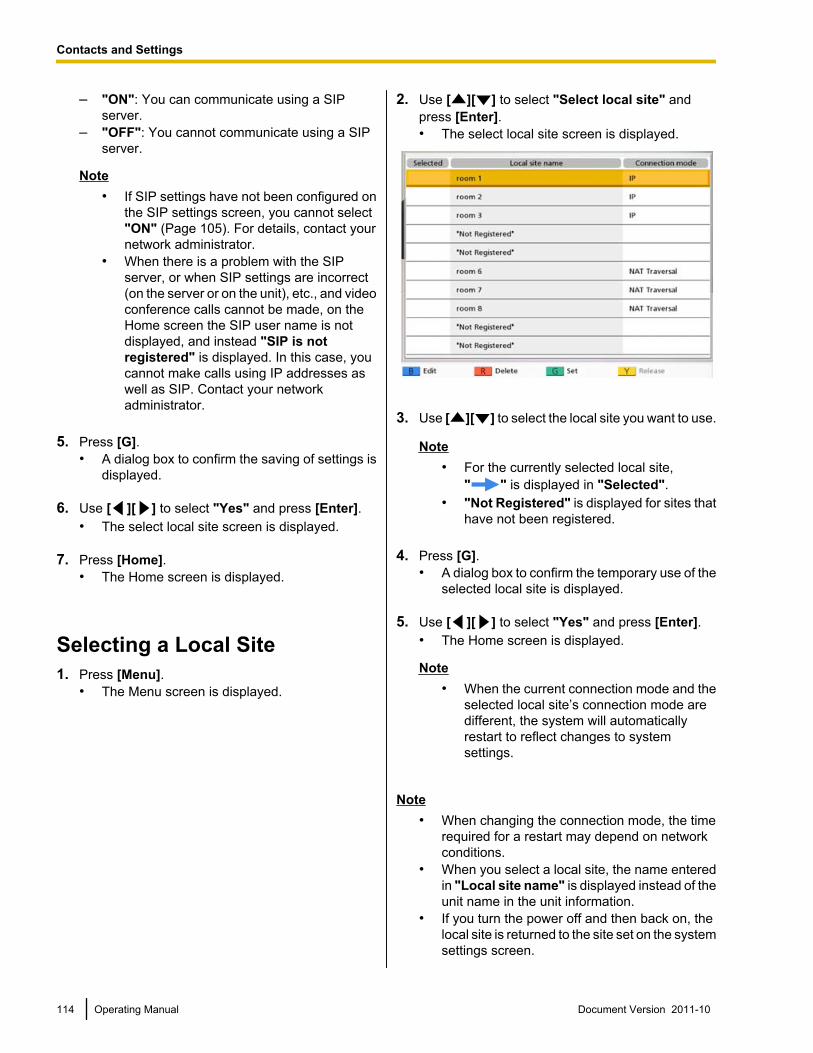
– "ON": You can communicate using a SIPserver.
– "OFF": You cannot communicate using a SIPserver.
Note• If SIP settings have not been configured on
the SIP settings screen, you cannot select"ON" (Page 105). For details, contact yournetwork administrator.
• When there is a problem with the SIPserver, or when SIP settings are incorrect(on the server or on the unit), etc., and videoconference calls cannot be made, on theHome screen the SIP user name is notdisplayed, and instead "SIP is notregistered" is displayed. In this case, youcannot make calls using IP addresses aswell as SIP. Contact your networkadministrator.
5. Press [G].• A dialog box to confirm the saving of settings is
displayed.
6. Use [ ][ ] to select "Yes" and press [Enter].• The select local site screen is displayed.
7. Press [Home].• The Home screen is displayed.
Selecting a Local Site1. Press [Menu].
• The Menu screen is displayed.
2. Use [ ][ ] to select "Select local site" andpress [Enter].• The select local site screen is displayed.
3. Use [ ][ ] to select the local site you want to use.
Note• For the currently selected local site,
" " is displayed in "Selected".• "Not Registered" is displayed for sites that
have not been registered.
4. Press [G].• A dialog box to confirm the temporary use of the
selected local site is displayed.
5. Use [ ][ ] to select "Yes" and press [Enter].• The Home screen is displayed.
Note• When the current connection mode and the
selected local site’s connection mode aredifferent, the system will automaticallyrestart to reflect changes to systemsettings.
Note• When changing the connection mode, the time
required for a restart may depend on networkconditions.
• When you select a local site, the name enteredin "Local site name" is displayed instead of theunit name in the unit information.
• If you turn the power off and then back on, thelocal site is returned to the site set on the systemsettings screen.
114 Operating Manual Document Version 2011-10
Contacts and Settings
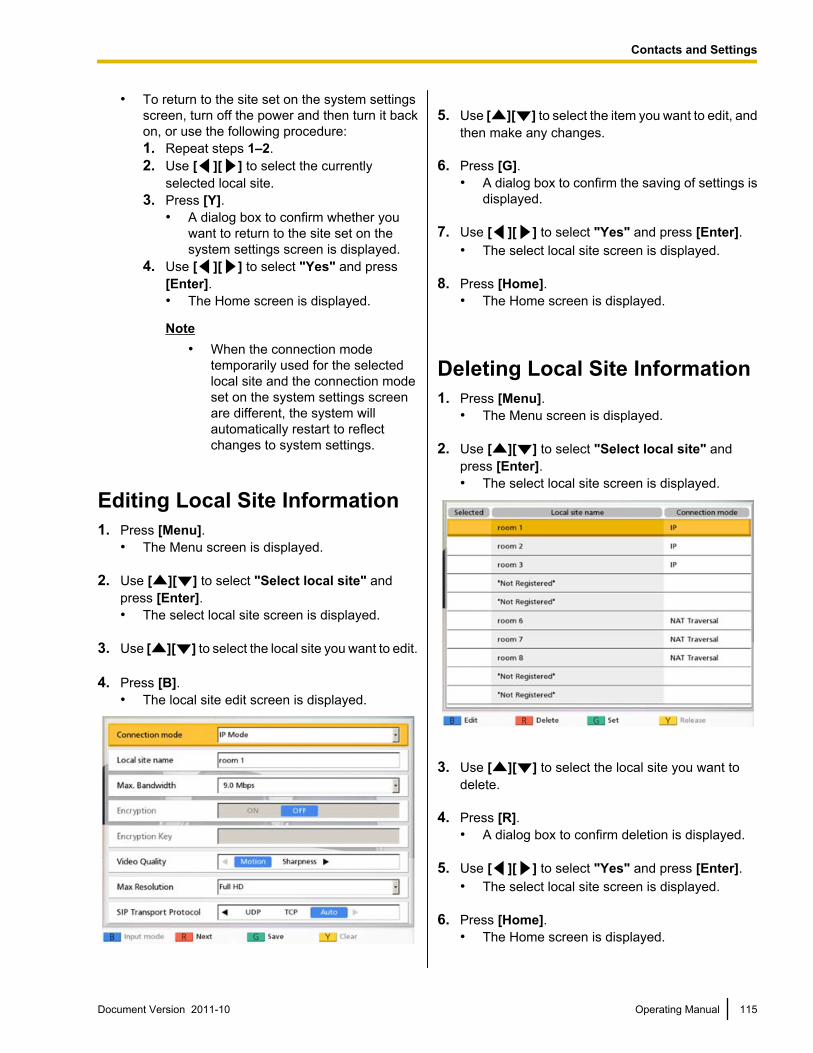
• To return to the site set on the system settingsscreen, turn off the power and then turn it backon, or use the following procedure:1. Repeat steps 1–2.2. Use [ ][ ] to select the currently
selected local site.3. Press [Y].
• A dialog box to confirm whether youwant to return to the site set on thesystem settings screen is displayed.
4. Use [ ][ ] to select "Yes" and press[Enter].• The Home screen is displayed.
Note• When the connection mode
temporarily used for the selectedlocal site and the connection modeset on the system settings screenare different, the system willautomatically restart to reflectchanges to system settings.
Editing Local Site Information1. Press [Menu].
• The Menu screen is displayed.
2. Use [ ][ ] to select "Select local site" andpress [Enter].• The select local site screen is displayed.
3. Use [ ][ ] to select the local site you want to edit.
4. Press [B].• The local site edit screen is displayed.
5. Use [ ][ ] to select the item you want to edit, andthen make any changes.
6. Press [G].• A dialog box to confirm the saving of settings is
displayed.
7. Use [ ][ ] to select "Yes" and press [Enter].• The select local site screen is displayed.
8. Press [Home].• The Home screen is displayed.
Deleting Local Site Information1. Press [Menu].
• The Menu screen is displayed.
2. Use [ ][ ] to select "Select local site" andpress [Enter].• The select local site screen is displayed.
3. Use [ ][ ] to select the local site you want todelete.
4. Press [R].• A dialog box to confirm deletion is displayed.
5. Use [ ][ ] to select "Yes" and press [Enter].• The select local site screen is displayed.
6. Press [Home].• The Home screen is displayed.
Document Version 2011-10 Operating Manual 115
Contacts and Settings
Inputting Letters and NumbersYou can use the remote control to input letters and numbers.The following tables detail the characters and numbers that can be input. The language that can be inputdepends on which language is selected through system settings.
Press the indicated button repeatedly to cycle through the characters and numbers assigned to that buttonuntil the character you want to input is displayed. If you want to input another character using the same button,press [ ] to move the input cursor to the right.
116 Operating Manual Document Version 2011-10
I
n
p
u
t
Input
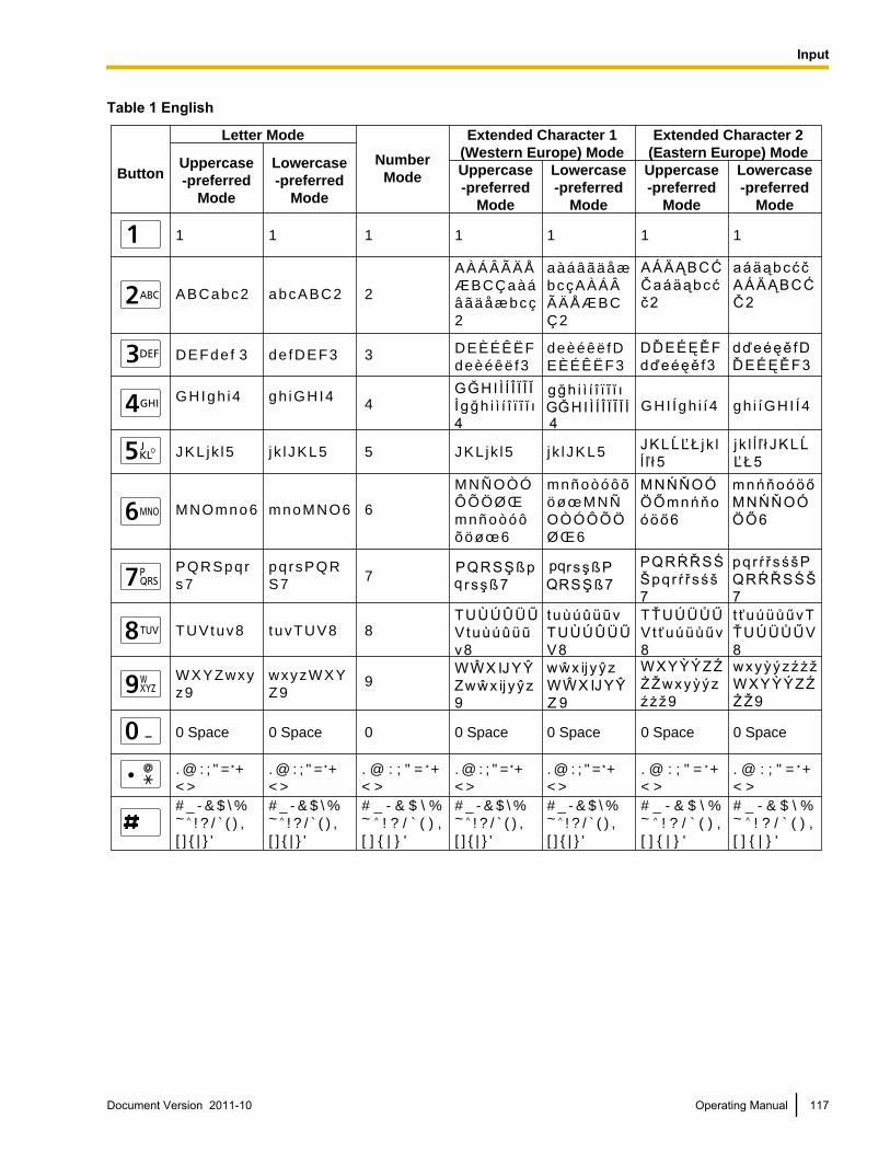
Table 1 English
Button
Letter Mode
Uppercase
-preferred
Mode
Uppercase
-preferred
Mode
Lowercase
-preferred
Mode
Uppercase
-preferred
Mode
Lowercase
-preferred
Mode
Lowercase
-preferred
Mode
Extended Character 1
(Western Europe) Mode
Extended Character 2
(Eastern Europe) ModeNumber
Mode
1 1 1 1 1 1
A B C a b c 2
A À Á Â Ã Ä Å
Æ B C Ç a à á
â ã ä å æ b c ç
2
a à á â ã ä å æ
b c ç A À Á Â
Ã Ä Å Æ B C
Ç 2
2
D E F d e f 3 3
G H I g h i 44
J K L j k l 5 5
M N O m n o 6 6
P Q R S p q r
s 77
T U V t u v 8 8
W X Y Z w x y
z 99
0 Space 0
. @ : ; " = +
< >
. @ : ; " = +
< >
# _ - & $ \ % ~ ̂ ! ? / ̀ ( ) ,
[ ] { | } '
1
a b c A B C 2
d e f D E F 3
g h i G H I 4
j k l J K L 5 J K L j k l 5 j k l J K L 5
m n o M N O 6
p q r s P Q R
S 7
t u v T U V 8
w x y z W X Y
Z 9
0 Space 0 Space 0 Space 0 Space 0 Space
. @ : ; " = +
< >
. @ : ; " = +
< >
. @ : ; " = +
< >
. @ : ; " = +
< >
. @ : ; " = +
< >
# _ - & $ \ % ~ ̂ ! ? / ̀ ( ) ,
[ ] { | } '
# _ - & $ \ % ~ ^ ! ? / ` ( ) ,
[ ] { | } '
# _ - & $ \ % ~ ̂ ! ? / ̀ ( ) ,
[ ] { | } '
# _ - & $ \ % ~ ̂ ! ? / ̀ ( ) ,
[ ] { | } '
# _ - & $ \ % ~ ^ ! ? / ` ( ) ,
[ ] { | } '
# _ - & $ \ % ~ ^ ! ? / ` ( ) ,
[ ] { | } '
D E È É Ê Ë F
d e è é ê ë f 3
d e è é ê ë f D
E È É Ê Ë F 3
G H I Í g h i í 4 g h i í G H I Í 4
M N Ñ O Ò Ó
Ô Õ Ö Ø Œ
m n ñ o ò ó ô
õ ö ø œ 6
m n ñ o ò ó ô õ
ö ø œ M N Ñ
O Ò Ó Ô Õ Ö
Ø Œ 6
Document Version 2011-10 Operating Manual 117
Input
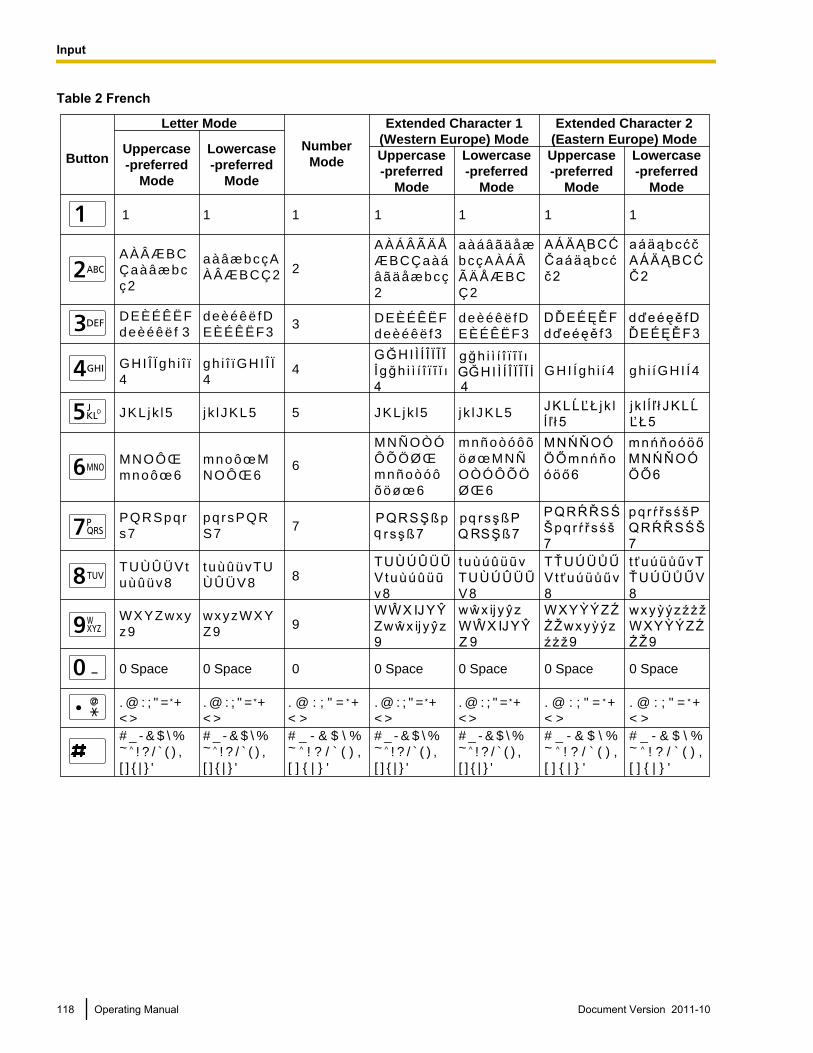
Table 2 French
Button
Letter Mode
Uppercase
-preferred
Mode
Uppercase
-preferred
Mode
Lowercase
-preferred
Mode
Uppercase
-preferred
Mode
Lowercase
-preferred
Mode
Lowercase
-preferred
Mode
Extended Character 1
(Western Europe) Mode
Extended Character 2
(Eastern Europe) ModeNumber
Mode
1 1 1 1 1 1
A À Â Æ B C
Ç a à â æ b c
ç 2
A À Á Â Ã Ä Å
Æ B C Ç a à á
â ã ä å æ b c ç
2
a à á â ã ä å æ
b c ç A À Á Â
Ã Ä Å Æ B C
Ç 2
2
D E È É Ê Ë F
d e è é ê ë f 33
G H I Î Ï g h i î ï
44
J K L j k l 5 5
M N O Ô Œ
m n o ô œ 66
P Q R S p q r
s 77
T U Ù Û Ü V t
u ù û ü v 88
W X Y Z w x y
z 99
0 Space 0
. @ : ; " = +
< >
. @ : ; " = +
< >
# _ - & $ \ % ~ ̂ ! ? / ̀ ( ) ,
[ ] { | } '
1
a à â æ b c ç A
À Â Æ B C Ç 2
d e è é ê ë f D
E È É Ê Ë F 3
g h i î ï G H I Î Ï
4
j k l J K L 5 J K L j k l 5 j k l J K L 5
m n o ô œ M
N O Ô Œ 6
p q r s P Q R
S 7
t u ù û ü v T U
Ù Û Ü V 8
w x y z W X Y
Z 9
0 Space 0 Space 0 Space 0 Space 0 Space
. @ : ; " = +
< >
. @ : ; " = +
< >
. @ : ; " = +
< >
. @ : ; " = +
< >
. @ : ; " = +
< >
# _ - & $ \ % ~ ̂ ! ? / ̀ ( ) ,
[ ] { | } '
# _ - & $ \ % ~ ^ ! ? / ` ( ) ,
[ ] { | } '
# _ - & $ \ % ~ ̂ ! ? / ̀ ( ) ,
[ ] { | } '
# _ - & $ \ % ~ ̂ ! ? / ̀ ( ) ,
[ ] { | } '
# _ - & $ \ % ~ ^ ! ? / ` ( ) ,
[ ] { | } '
# _ - & $ \ % ~ ^ ! ? / ` ( ) ,
[ ] { | } '
D E È É Ê Ë F
d e è é ê ë f 3
d e è é ê ë f D
E È É Ê Ë F 3
G H I Í g h i í 4 g h i í G H I Í 4
M N Ñ O Ò Ó
Ô Õ Ö Ø Œ
m n ñ o ò ó ô
õ ö ø œ 6
m n ñ o ò ó ô õ
ö ø œ M N Ñ
O Ò Ó Ô Õ Ö
Ø Œ 6
118 Operating Manual Document Version 2011-10
Input
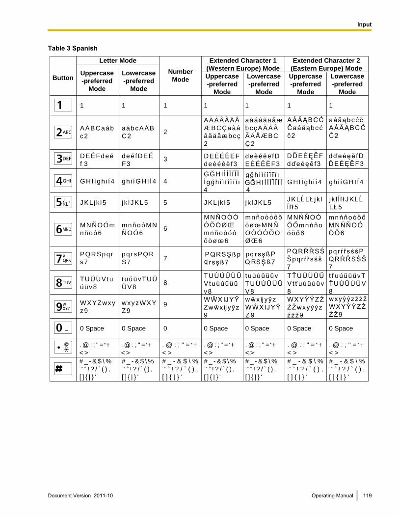
Table 3 Spanish
Button
Letter Mode
Uppercase
-preferred
Mode
Uppercase
-preferred
Mode
Lowercase
-preferred
Mode
Uppercase
-preferred
Mode
Lowercase
-preferred
Mode
Lowercase
-preferred
Mode
Extended Character 1
(Western Europe) Mode
Extended Character 2
(Eastern Europe) ModeNumber
Mode
1 1 1 1 1 1
A Á B C a á b
c 2
A À Á Â Ã Ä Å
Æ B C Ç a à á
â ã ä å æ b c ç
2
a à á â ã ä å æ
b c ç A À Á Â
Ã Ä Å Æ B C
Ç 2
2
D E É F d e é
f 33
G H I Í g h i í 4 4
J K L j k l 5 5
M N Ñ O Ó m
n ñ o ó 66
P Q R S p q r
s 77
T U Ú Ü V t u
ú ü v 88
W X Y Z w x y
z 99
0 Space 0
. @ : ; " = +
< >
. @ : ; " = +
< >
# _ - & $ \ % ~ ̂ ! ? / ̀ ( ) ,
[ ] { | } '
1
a á b c A Á B
C 2
d e é f D E É
F 3
g h i í G H I Í 4
j k l J K L 5 J K L j k l 5 j k l J K L 5
m n ñ o ó M N
Ñ O Ó 6
p q r s P Q R
S 7
t u ú ü v T U Ú
Ü V 8
w x y z W X Y
Z 9
0 Space 0 Space 0 Space 0 Space 0 Space
. @ : ; " = +
< >
. @ : ; " = +
< >
. @ : ; " = +
< >
. @ : ; " = +
< >
. @ : ; " = +
< >
# _ - & $ \ % ~ ̂ ! ? / ̀ ( ) ,
[ ] { | } '
# _ - & $ \ % ~ ^ ! ? / ` ( ) ,
[ ] { | } '
# _ - & $ \ % ~ ̂ ! ? / ̀ ( ) ,
[ ] { | } '
# _ - & $ \ % ~ ̂ ! ? / ̀ ( ) ,
[ ] { | } '
# _ - & $ \ % ~ ^ ! ? / ` ( ) ,
[ ] { | } '
# _ - & $ \ % ~ ^ ! ? / ` ( ) ,
[ ] { | } '
D E È É Ê Ë F
d e è é ê ë f 3
d e è é ê ë f D
E È É Ê Ë F 3
G H I Í g h i í 4 g h i í G H I Í 4
M N Ñ O Ò Ó
Ô Õ Ö Ø Œ
m n ñ o ò ó ô
õ ö ø œ 6
m n ñ o ò ó ô õ
ö ø œ M N Ñ
O Ò Ó Ô Õ Ö
Ø Œ 6
Document Version 2011-10 Operating Manual 119
Input
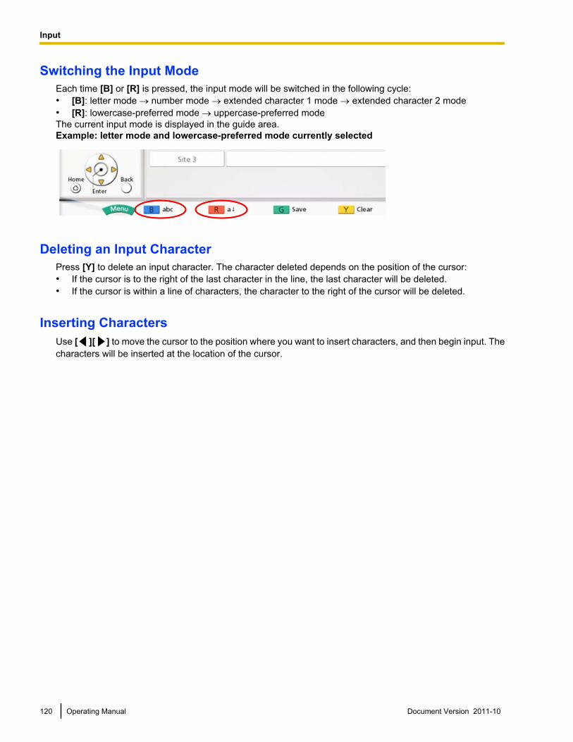
Switching the Input ModeEach time [B] or [R] is pressed, the input mode will be switched in the following cycle:• [B]: letter mode ® number mode ® extended character 1 mode ® extended character 2 mode• [R]: lowercase-preferred mode ® uppercase-preferred modeThe current input mode is displayed in the guide area.Example: letter mode and lowercase-preferred mode currently selected
Deleting an Input CharacterPress [Y] to delete an input character. The character deleted depends on the position of the cursor:• If the cursor is to the right of the last character in the line, the last character will be deleted.• If the cursor is within a line of characters, the character to the right of the cursor will be deleted.
Inserting CharactersUse [ ][ ] to move the cursor to the position where you want to insert characters, and then begin input. Thecharacters will be inserted at the location of the cursor.
120 Operating Manual Document Version 2011-10
Input
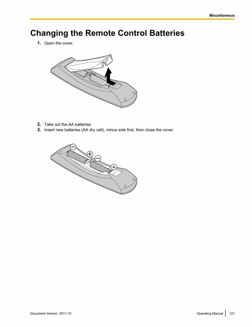
Changing the Remote Control Batteries1. Open the cover.
2. Take out the AA batteries.3. Insert new batteries (AA dry cell), minus side first, then close the cover.
Document Version 2011-10 Operating Manual 121
M
i
s
c
e
l
l
a
n
e
o
u
s
Miscellaneous
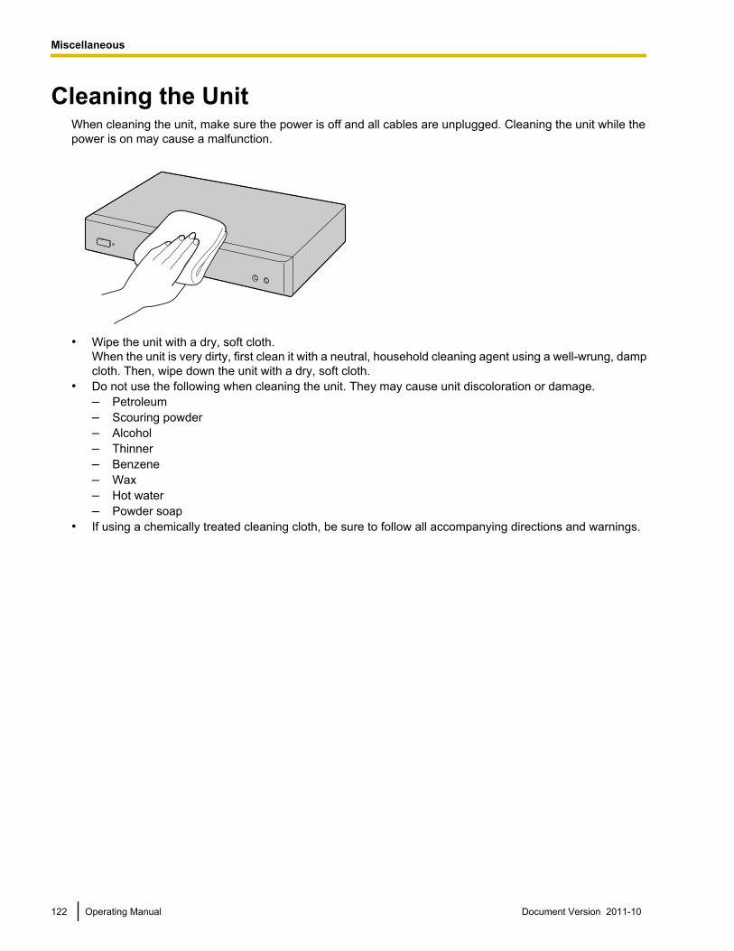
Cleaning the UnitWhen cleaning the unit, make sure the power is off and all cables are unplugged. Cleaning the unit while thepower is on may cause a malfunction.
• Wipe the unit with a dry, soft cloth.When the unit is very dirty, first clean it with a neutral, household cleaning agent using a well-wrung, dampcloth. Then, wipe down the unit with a dry, soft cloth.
• Do not use the following when cleaning the unit. They may cause unit discoloration or damage.– Petroleum– Scouring powder– Alcohol– Thinner– Benzene– Wax– Hot water– Powder soap
• If using a chemically treated cleaning cloth, be sure to follow all accompanying directions and warnings.
122 Operating Manual Document Version 2011-10
Miscellaneous
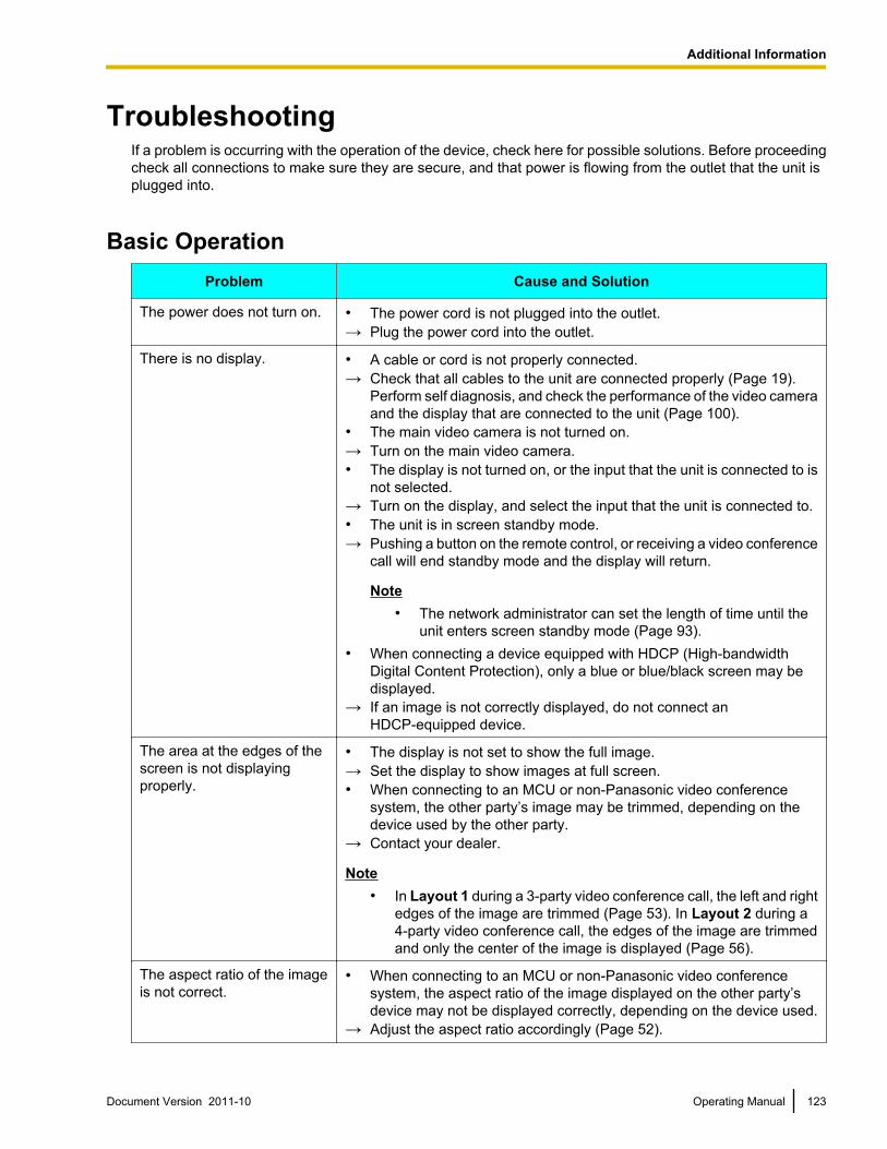
TroubleshootingIf a problem is occurring with the operation of the device, check here for possible solutions. Before proceedingcheck all connections to make sure they are secure, and that power is flowing from the outlet that the unit isplugged into.
Basic OperationProblem Cause and Solution
The power does not turn on. • The power cord is not plugged into the outlet.→ Plug the power cord into the outlet.
There is no display. • A cable or cord is not properly connected.→ Check that all cables to the unit are connected properly (Page 19).
Perform self diagnosis, and check the performance of the video cameraand the display that are connected to the unit (Page 100).
• The main video camera is not turned on.→ Turn on the main video camera.• The display is not turned on, or the input that the unit is connected to is
not selected.→ Turn on the display, and select the input that the unit is connected to.• The unit is in screen standby mode.→ Pushing a button on the remote control, or receiving a video conference
call will end standby mode and the display will return.
Note• The network administrator can set the length of time until the
unit enters screen standby mode (Page 93).• When connecting a device equipped with HDCP (High-bandwidth
Digital Content Protection), only a blue or blue/black screen may bedisplayed.
→ If an image is not correctly displayed, do not connect anHDCP-equipped device.
The area at the edges of thescreen is not displayingproperly.
• The display is not set to show the full image.→ Set the display to show images at full screen.• When connecting to an MCU or non-Panasonic video conference
system, the other party’s image may be trimmed, depending on thedevice used by the other party.
→ Contact your dealer.
Note• In Layout 1 during a 3-party video conference call, the left and right
edges of the image are trimmed (Page 53). In Layout 2 during a4-party video conference call, the edges of the image are trimmedand only the center of the image is displayed (Page 56).
The aspect ratio of the imageis not correct.
• When connecting to an MCU or non-Panasonic video conferencesystem, the aspect ratio of the image displayed on the other party’sdevice may not be displayed correctly, depending on the device used.
→ Adjust the aspect ratio accordingly (Page 52).
Document Version 2011-10 Operating Manual 123
A
d
d
i
t
i
o
n
a
l
I
n
f
o
r
m
a
t
i
o
n
Additional Information
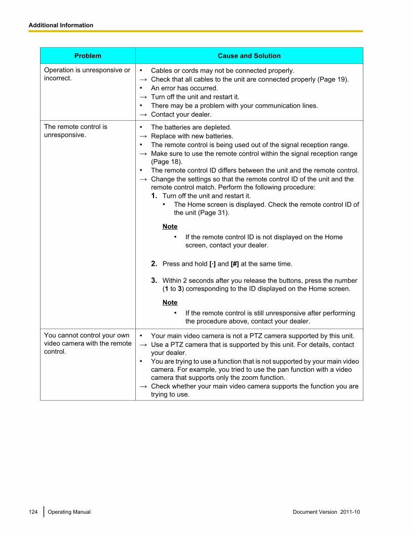
Problem Cause and Solution
Operation is unresponsive orincorrect.
• Cables or cords may not be connected properly.→ Check that all cables to the unit are connected properly (Page 19).• An error has occurred.→ Turn off the unit and restart it.• There may be a problem with your communication lines.→ Contact your dealer.
The remote control isunresponsive.
• The batteries are depleted.→ Replace with new batteries.• The remote control is being used out of the signal reception range.→ Make sure to use the remote control within the signal reception range
(Page 18).• The remote control ID differs between the unit and the remote control.→ Change the settings so that the remote control ID of the unit and the
remote control match. Perform the following procedure:1. Turn off the unit and restart it.
• The Home screen is displayed. Check the remote control ID ofthe unit (Page 31).
Note• If the remote control ID is not displayed on the Home
screen, contact your dealer.
2. Press and hold [·] and [#] at the same time.
3. Within 2 seconds after you release the buttons, press the number(1 to 3) corresponding to the ID displayed on the Home screen.
Note• If the remote control is still unresponsive after performing
the procedure above, contact your dealer.
You cannot control your ownvideo camera with the remotecontrol.
• Your main video camera is not a PTZ camera supported by this unit.→ Use a PTZ camera that is supported by this unit. For details, contact
your dealer.• You are trying to use a function that is not supported by your main video
camera. For example, you tried to use the pan function with a videocamera that supports only the zoom function.
→ Check whether your main video camera supports the function you aretrying to use.
124 Operating Manual Document Version 2011-10
Additional Information
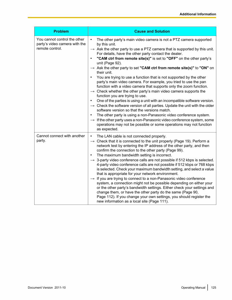
Problem Cause and Solution
You cannot control the otherparty’s video camera with theremote control.
• The other party’s main video camera is not a PTZ camera supportedby this unit.
→ Ask the other party to use a PTZ camera that is supported by this unit.For details, have the other party contact the dealer.
• "CAM ctrl from remote site(s)" is set to "OFF" on the other party’sunit (Page 92).
→ Ask the other party to set "CAM ctrl from remote site(s)" to "ON" ontheir unit.
• You are trying to use a function that is not supported by the otherparty’s main video camera. For example, you tried to use the panfunction with a video camera that supports only the zoom function.
→ Check whether the other party’s main video camera supports thefunction you are trying to use.
• One of the parties is using a unit with an incompatible software version.→ Check the software version of all parties. Update the unit with the older
software version so that the versions match.• The other party is using a non-Panasonic video conference system.→ If the other party uses a non-Panasonic video conference system, some
operations may not be possible or some operations may not functionas expected.
Cannot connect with anotherparty.
• The LAN cable is not connected properly.→ Check that it is connected to the unit properly (Page 19). Perform a
network test by entering the IP address of the other party, and thenconfirm the connection to the other party (Page 99).
• The maximum bandwidth setting is incorrect.→ 3-party video conference calls are not possible if 512 kbps is selected.
4-party video conference calls are not possible if 512 kbps or 768 kbpsis selected. Check your maximum bandwidth setting, and select a valuethat is appropriate for your network environment.
→ If you are trying to connect to a non-Panasonic video conferencesystem, a connection might not be possible depending on either youror the other party’s bandwidth settings. Either check your settings andchange them, or have the other party do the same (Page 90,Page 112). If you change your own settings, you should register thenew information as a local site (Page 111).
Document Version 2011-10 Operating Manual 125
Additional Information
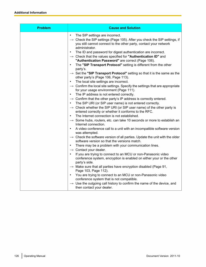
Problem Cause and Solution
• The SIP settings are incorrect.→ Check the SIP settings (Page 105). After you check the SIP settings, if
you still cannot connect to the other party, contact your networkadministrator.
• The ID and password for digest authentication are incorrect.→ Check that the values specified for "Authentication ID" and
"Authentication Password" are correct (Page 106).• The "SIP Transport Protocol" setting is different from the other
party’s.→ Set the "SIP Transport Protocol" setting so that it is the same as the
other party’s (Page 106, Page 113).• The local site settings are incorrect.→ Confirm the local site settings. Specify the settings that are appropriate
for your usage environment (Page 111).• The IP address is not entered correctly.→ Confirm that the other party’s IP address is correctly entered.• The SIP URI (or SIP user name) is not entered correctly.→ Check whether the SIP URI (or SIP user name) of the other party is
entered correctly or whether it conforms to the RFC.• The Internet connection is not established.→ Some hubs, routers, etc. can take 10 seconds or more to establish an
Internet connection.• A video conference call to a unit with an incompatible software version
was attempted.→ Check the software version of all parties. Update the unit with the older
software version so that the versions match.• There may be a problem with your communication lines.→ Contact your dealer.• If you are trying to connect to an MCU or non-Panasonic video
conference system, encryption is enabled on either your or the otherparty’s side.
→ Make sure that all parties have encryption disabled (Page 91,Page 103, Page 112).
• You are trying to connect to an MCU or non-Panasonic videoconference system that is not compatible.
→ Use the outgoing call history to confirm the name of the device, andthen contact your dealer.
126 Operating Manual Document Version 2011-10
Additional Information
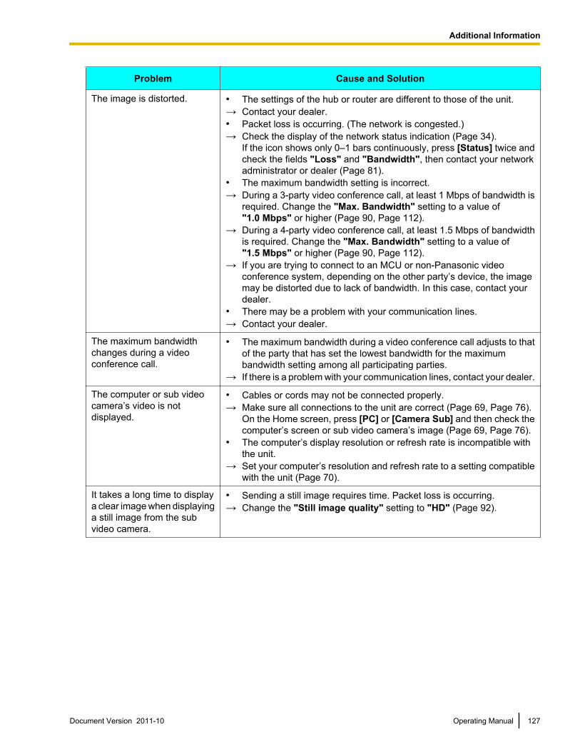
Problem Cause and Solution
The image is distorted. • The settings of the hub or router are different to those of the unit.→ Contact your dealer.• Packet loss is occurring. (The network is congested.)→ Check the display of the network status indication (Page 34).
If the icon shows only 0–1 bars continuously, press [Status] twice andcheck the fields "Loss" and "Bandwidth", then contact your networkadministrator or dealer (Page 81).
• The maximum bandwidth setting is incorrect.→ During a 3-party video conference call, at least 1 Mbps of bandwidth is
required. Change the "Max. Bandwidth" setting to a value of"1.0 Mbps" or higher (Page 90, Page 112).
→ During a 4-party video conference call, at least 1.5 Mbps of bandwidthis required. Change the "Max. Bandwidth" setting to a value of"1.5 Mbps" or higher (Page 90, Page 112).
→ If you are trying to connect to an MCU or non-Panasonic videoconference system, depending on the other party’s device, the imagemay be distorted due to lack of bandwidth. In this case, contact yourdealer.
• There may be a problem with your communication lines.→ Contact your dealer.
The maximum bandwidthchanges during a videoconference call.
• The maximum bandwidth during a video conference call adjusts to thatof the party that has set the lowest bandwidth for the maximumbandwidth setting among all participating parties.
→ If there is a problem with your communication lines, contact your dealer.
The computer or sub videocamera’s video is notdisplayed.
• Cables or cords may not be connected properly.→ Make sure all connections to the unit are correct (Page 69, Page 76).
On the Home screen, press [PC] or [Camera Sub] and then check thecomputer’s screen or sub video camera’s image (Page 69, Page 76).
• The computer’s display resolution or refresh rate is incompatible withthe unit.
→ Set your computer’s resolution and refresh rate to a setting compatiblewith the unit (Page 70).
It takes a long time to displaya clear image when displayinga still image from the subvideo camera.
• Sending a still image requires time. Packet loss is occurring.→ Change the "Still image quality" setting to "HD" (Page 92).
Document Version 2011-10 Operating Manual 127
Additional Information
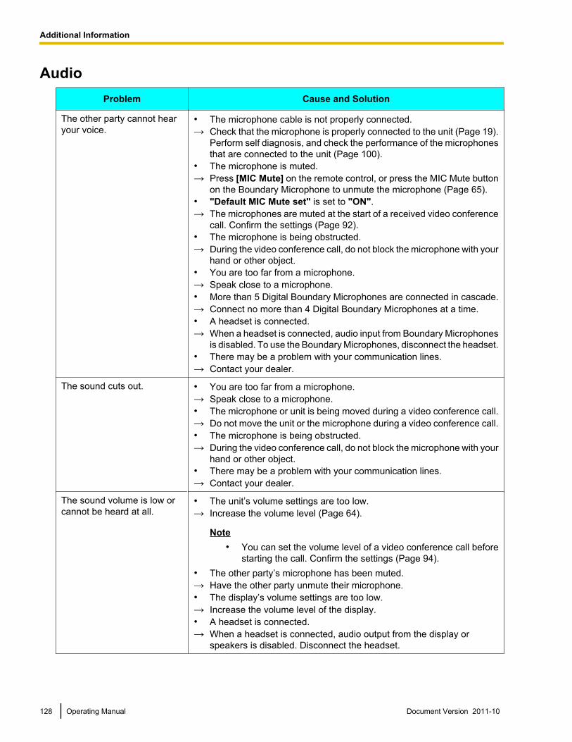
AudioProblem Cause and Solution
The other party cannot hearyour voice.
• The microphone cable is not properly connected.→ Check that the microphone is properly connected to the unit (Page 19).
Perform self diagnosis, and check the performance of the microphonesthat are connected to the unit (Page 100).
• The microphone is muted.→ Press [MIC Mute] on the remote control, or press the MIC Mute button
on the Boundary Microphone to unmute the microphone (Page 65).• "Default MIC Mute set" is set to "ON".→ The microphones are muted at the start of a received video conference
call. Confirm the settings (Page 92).• The microphone is being obstructed.→ During the video conference call, do not block the microphone with your
hand or other object.• You are too far from a microphone.→ Speak close to a microphone.• More than 5 Digital Boundary Microphones are connected in cascade.→ Connect no more than 4 Digital Boundary Microphones at a time.• A headset is connected.→ When a headset is connected, audio input from Boundary Microphones
is disabled. To use the Boundary Microphones, disconnect the headset.• There may be a problem with your communication lines.→ Contact your dealer.
The sound cuts out. • You are too far from a microphone.→ Speak close to a microphone.• The microphone or unit is being moved during a video conference call.→ Do not move the unit or the microphone during a video conference call.• The microphone is being obstructed.→ During the video conference call, do not block the microphone with your
hand or other object.• There may be a problem with your communication lines.→ Contact your dealer.
The sound volume is low orcannot be heard at all.
• The unit’s volume settings are too low.→ Increase the volume level (Page 64).
Note• You can set the volume level of a video conference call before
starting the call. Confirm the settings (Page 94).• The other party’s microphone has been muted.→ Have the other party unmute their microphone.• The display’s volume settings are too low.→ Increase the volume level of the display.• A headset is connected.→ When a headset is connected, audio output from the display or
speakers is disabled. Disconnect the headset.
128 Operating Manual Document Version 2011-10
Additional Information
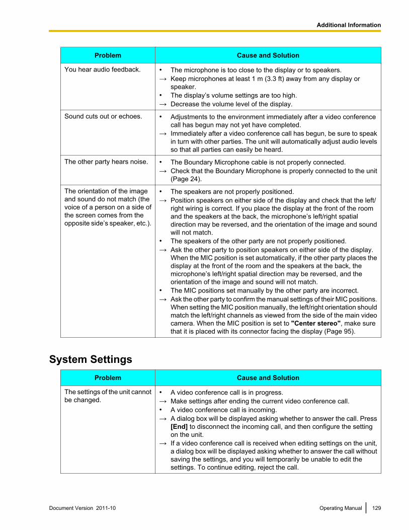
Problem Cause and Solution
You hear audio feedback. • The microphone is too close to the display or to speakers.→ Keep microphones at least 1 m (3.3 ft) away from any display or
speaker.• The display’s volume settings are too high.→ Decrease the volume level of the display.
Sound cuts out or echoes. • Adjustments to the environment immediately after a video conferencecall has begun may not yet have completed.
→ Immediately after a video conference call has begun, be sure to speakin turn with other parties. The unit will automatically adjust audio levelsso that all parties can easily be heard.
The other party hears noise. • The Boundary Microphone cable is not properly connected.→ Check that the Boundary Microphone is properly connected to the unit
(Page 24).
The orientation of the imageand sound do not match (thevoice of a person on a side ofthe screen comes from theopposite side’s speaker, etc.).
• The speakers are not properly positioned.→ Position speakers on either side of the display and check that the left/
right wiring is correct. If you place the display at the front of the roomand the speakers at the back, the microphone’s left/right spatialdirection may be reversed, and the orientation of the image and soundwill not match.
• The speakers of the other party are not properly positioned.→ Ask the other party to position speakers on either side of the display.
When the MIC position is set automatically, if the other party places thedisplay at the front of the room and the speakers at the back, themicrophone’s left/right spatial direction may be reversed, and theorientation of the image and sound will not match.
• The MIC positions set manually by the other party are incorrect.→ Ask the other party to confirm the manual settings of their MIC positions.
When setting the MIC position manually, the left/right orientation shouldmatch the left/right channels as viewed from the side of the main videocamera. When the MIC position is set to "Center stereo", make surethat it is placed with its connector facing the display (Page 95).
System SettingsProblem Cause and Solution
The settings of the unit cannotbe changed.
• A video conference call is in progress.→ Make settings after ending the current video conference call.• A video conference call is incoming.→ A dialog box will be displayed asking whether to answer the call. Press
[End] to disconnect the incoming call, and then configure the settingon the unit.
→ If a video conference call is received when editing settings on the unit,a dialog box will be displayed asking whether to answer the call withoutsaving the settings, and you will temporarily be unable to edit thesettings. To continue editing, reject the call.
Document Version 2011-10 Operating Manual 129
Additional Information
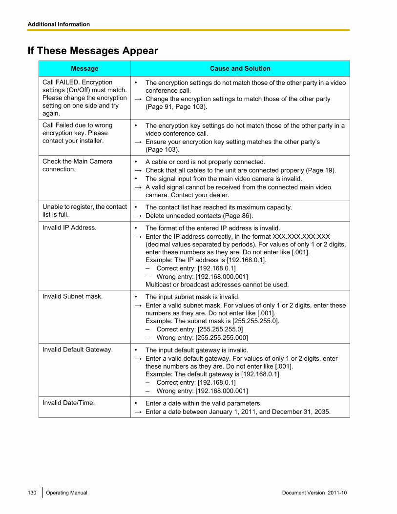
If These Messages AppearMessage Cause and Solution
Call FAILED. Encryptionsettings (On/Off) must match.Please change the encryptionsetting on one side and tryagain.
• The encryption settings do not match those of the other party in a videoconference call.
→ Change the encryption settings to match those of the other party(Page 91, Page 103).
Call Failed due to wrongencryption key. Pleasecontact your installer.
• The encryption key settings do not match those of the other party in avideo conference call.
→ Ensure your encryption key setting matches the other party’s(Page 103).
Check the Main Cameraconnection.
• A cable or cord is not properly connected.→ Check that all cables to the unit are connected properly (Page 19).• The signal input from the main video camera is invalid.→ A valid signal cannot be received from the connected main video
camera. Contact your dealer.
Unable to register, the contactlist is full.
• The contact list has reached its maximum capacity.→ Delete unneeded contacts (Page 86).
Invalid IP Address. • The format of the entered IP address is invalid.→ Enter the IP address correctly, in the format XXX.XXX.XXX.XXX
(decimal values separated by periods). For values of only 1 or 2 digits,enter these numbers as they are. Do not enter like [.001].Example: The IP address is [192.168.0.1].– Correct entry: [192.168.0.1]– Wrong entry: [192.168.000.001]Multicast or broadcast addresses cannot be used.
Invalid Subnet mask. • The input subnet mask is invalid.→ Enter a valid subnet mask. For values of only 1 or 2 digits, enter these
numbers as they are. Do not enter like [.001].Example: The subnet mask is [255.255.255.0].– Correct entry: [255.255.255.0]– Wrong entry: [255.255.255.000]
Invalid Default Gateway. • The input default gateway is invalid.→ Enter a valid default gateway. For values of only 1 or 2 digits, enter
these numbers as they are. Do not enter like [.001].Example: The default gateway is [192.168.0.1].– Correct entry: [192.168.0.1]– Wrong entry: [192.168.000.001]
Invalid Date/Time. • Enter a date within the valid parameters.→ Enter a date between January 1, 2011, and December 31, 2035.
130 Operating Manual Document Version 2011-10
Additional Information
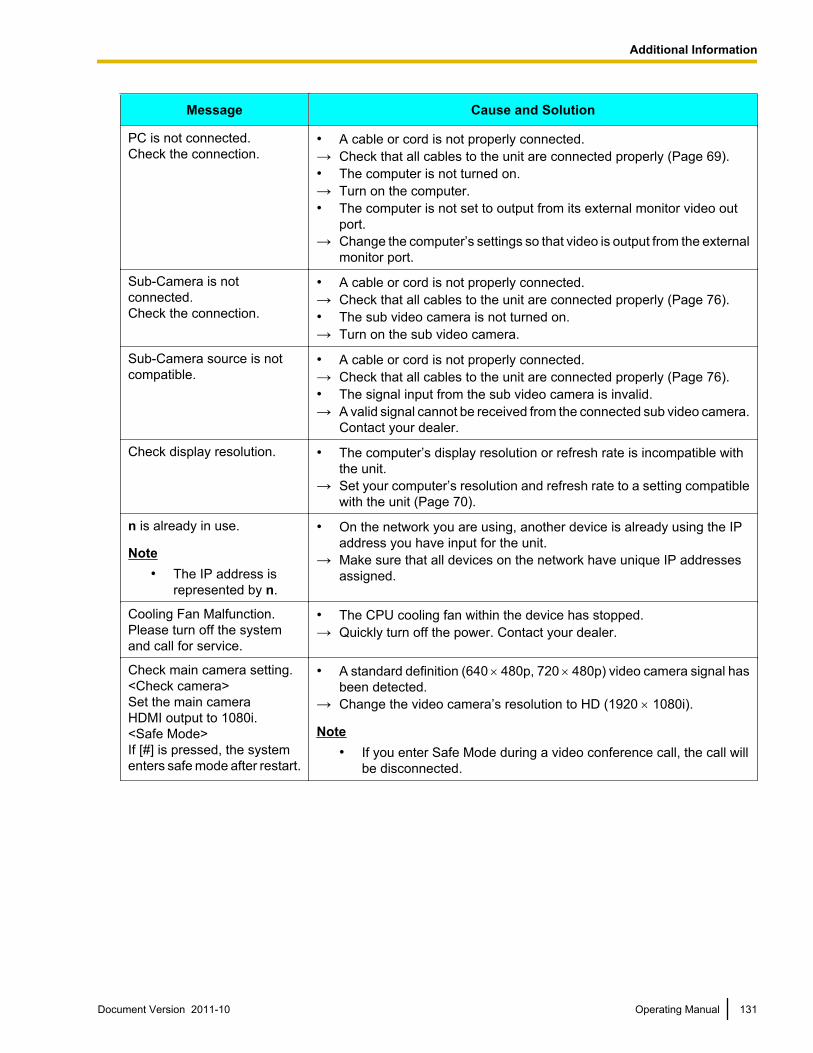
Message Cause and Solution
PC is not connected.Check the connection.
• A cable or cord is not properly connected.→ Check that all cables to the unit are connected properly (Page 69).• The computer is not turned on.→ Turn on the computer.• The computer is not set to output from its external monitor video out
port.→ Change the computer’s settings so that video is output from the external
monitor port.
Sub-Camera is notconnected.Check the connection.
• A cable or cord is not properly connected.→ Check that all cables to the unit are connected properly (Page 76).• The sub video camera is not turned on.→ Turn on the sub video camera.
Sub-Camera source is notcompatible.
• A cable or cord is not properly connected.→ Check that all cables to the unit are connected properly (Page 76).• The signal input from the sub video camera is invalid.→ A valid signal cannot be received from the connected sub video camera.
Contact your dealer.
Check display resolution. • The computer’s display resolution or refresh rate is incompatible withthe unit.
→ Set your computer’s resolution and refresh rate to a setting compatiblewith the unit (Page 70).
n is already in use.
Note• The IP address is
represented by n.
• On the network you are using, another device is already using the IPaddress you have input for the unit.
→ Make sure that all devices on the network have unique IP addressesassigned.
Cooling Fan Malfunction.Please turn off the systemand call for service.
• The CPU cooling fan within the device has stopped.→ Quickly turn off the power. Contact your dealer.
Check main camera setting.<Check camera>Set the main cameraHDMI output to 1080i.<Safe Mode>If [#] is pressed, the systementers safe mode after restart.
• A standard definition (640 ́ 480p, 720 ́ 480p) video camera signal hasbeen detected.
→ Change the video camera’s resolution to HD (1920 ´ 1080i).
Note• If you enter Safe Mode during a video conference call, the call will
be disconnected.
Document Version 2011-10 Operating Manual 131
Additional Information
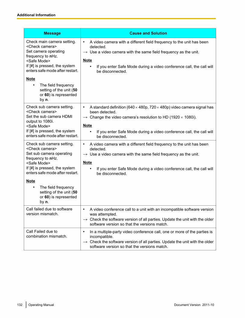
Message Cause and Solution
Check main camera setting.<Check camera>Set camera operatingfrequency to nHz.<Safe Mode>If [#] is pressed, the systementers safe mode after restart.
Note• The field frequency
setting of the unit (50or 60) is representedby n.
• A video camera with a different field frequency to the unit has beendetected.
→ Use a video camera with the same field frequency as the unit.
Note• If you enter Safe Mode during a video conference call, the call will
be disconnected.
Check sub camera setting.<Check camera>Set the sub camera HDMIoutput to 1080i.<Safe Mode>If [#] is pressed, the systementers safe mode after restart.
• A standard definition (640 ́ 480p, 720 ́ 480p) video camera signal hasbeen detected.
→ Change the video camera’s resolution to HD (1920 ´ 1080i).
Note• If you enter Safe Mode during a video conference call, the call will
be disconnected.
Check sub camera setting.<Check camera>Set sub camera operatingfrequency to nHz.<Safe Mode>If [#] is pressed, the systementers safe mode after restart.
Note• The field frequency
setting of the unit (50or 60) is representedby n.
• A video camera with a different field frequency to the unit has beendetected.
→ Use a video camera with the same field frequency as the unit.
Note• If you enter Safe Mode during a video conference call, the call will
be disconnected.
Call failed due to softwareversion mismatch.
• A video conference call to a unit with an incompatible software versionwas attempted.
→ Check the software version of all parties. Update the unit with the oldersoftware version so that the versions match.
Call Failed due tocombination mismatch.
• In a multiple-party video conference call, one or more of the parties isincompatible.
→ Check the software version of all parties. Update the unit with the oldersoftware version so that the versions match.
132 Operating Manual Document Version 2011-10
Additional Information
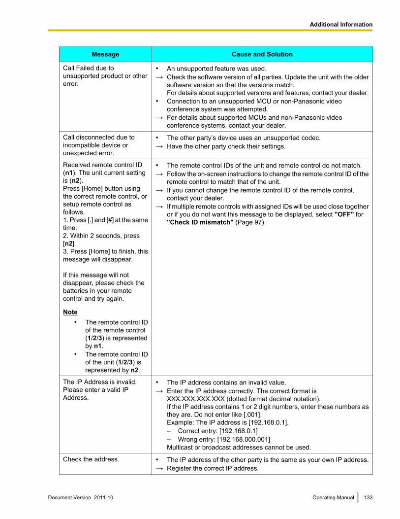
Message Cause and Solution
Call Failed due tounsupported product or othererror.
• An unsupported feature was used.→ Check the software version of all parties. Update the unit with the older
software version so that the versions match.For details about supported versions and features, contact your dealer.
• Connection to an unsupported MCU or non-Panasonic videoconference system was attempted.
→ For details about supported MCUs and non-Panasonic videoconference systems, contact your dealer.
Call disconnected due toincompatible device orunexpected error.
• The other party’s device uses an unsupported codec.→ Have the other party check their settings.
Received remote control ID(n1). The unit current settingis (n2).Press [Home] button usingthe correct remote control, orsetup remote control asfollows.1. Press [.] and [#] at the sametime.2. Within 2 seconds, press[n2].3. Press [Home] to finish, thismessage will disappear.
If this message will notdisappear, please check thebatteries in your remotecontrol and try again.
Note• The remote control ID
of the remote control(1/2/3) is representedby n1.
• The remote control IDof the unit (1/2/3) isrepresented by n2.
• The remote control IDs of the unit and remote control do not match.→ Follow the on-screen instructions to change the remote control ID of the
remote control to match that of the unit.→ If you cannot change the remote control ID of the remote control,
contact your dealer.→ If multiple remote controls with assigned IDs will be used close together
or if you do not want this message to be displayed, select "OFF" for"Check ID mismatch" (Page 97).
The IP Address is invalid.Please enter a valid IPAddress.
• The IP address contains an invalid value.→ Enter the IP address correctly. The correct format is
XXX.XXX.XXX.XXX (dotted format decimal notation).If the IP address contains 1 or 2 digit numbers, enter these numbers asthey are. Do not enter like [.001].Example: The IP address is [192.168.0.1].– Correct entry: [192.168.0.1]– Wrong entry: [192.168.000.001]Multicast or broadcast addresses cannot be used.
Check the address. • The IP address of the other party is the same as your own IP address.→ Register the correct IP address.
Document Version 2011-10 Operating Manual 133
Additional Information
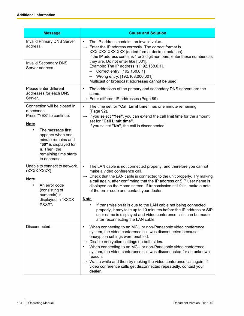
Message Cause and Solution
Invalid Primary DNS Serveraddress.
• The IP address contains an invalid value.→ Enter the IP address correctly. The correct format is
XXX.XXX.XXX.XXX (dotted format decimal notation).If the IP address contains 1 or 2 digit numbers, enter these numbers asthey are. Do not enter like [.001].Example: The IP address is [192.168.0.1].– Correct entry: [192.168.0.1]– Wrong entry: [192.168.000.001]Multicast or broadcast addresses cannot be used.
Invalid Secondary DNSServer address.
Please enter differentaddresses for each DNSServer.
• The addresses of the primary and secondary DNS servers are thesame.
→ Enter different IP addresses (Page 89).
Connection will be closed inn seconds.Press "YES" to continue.
Note• The message first
appears when oneminute remains and"60" is displayed forn. Then, theremaining time startsto decrease.
• The time set for "Call Limit time" has one minute remaining(Page 92).
→ If you select "Yes", you can extend the call limit time for the amountset for "Call Limit time".If you select "No", the call is disconnected.
Unable to connect to network.(XXXX XXXX)
Note• An error code
(consisting ofnumerals) isdisplayed in "XXXXXXXX".
• The LAN cable is not connected properly, and therefore you cannotmake a video conference call.
→ Check that the LAN cable is connected to the unit properly. Try makinga call again, after confirming that the IP address or SIP user name isdisplayed on the Home screen. If transmission still fails, make a noteof the error code and contact your dealer.
Note• If transmission fails due to the LAN cable not being connected
properly, it may take up to 10 minutes before the IP address or SIPuser name is displayed and video conference calls can be madeafter reconnecting the LAN cable.
Disconnected. • When connecting to an MCU or non-Panasonic video conferencesystem, the video conference call was disconnected becauseencryption settings were enabled.
→ Disable encryption settings on both sides.• When connecting to an MCU or non-Panasonic video conference
system, the video conference call was disconnected for an unknownreason.
→ Wait a while and then try making the video conference call again. Ifvideo conference calls get disconnected repeatedly, contact yourdealer.
134 Operating Manual Document Version 2011-10
Additional Information
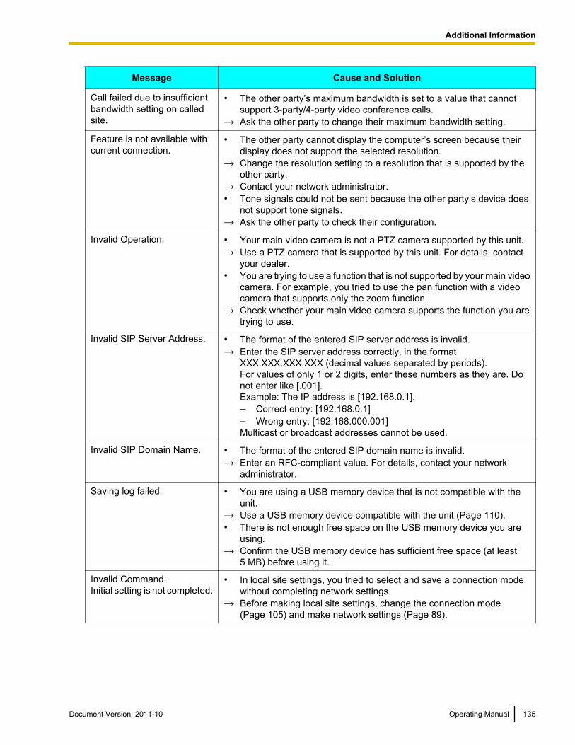
Message Cause and Solution
Call failed due to insufficientbandwidth setting on calledsite.
• The other party’s maximum bandwidth is set to a value that cannotsupport 3-party/4-party video conference calls.
→ Ask the other party to change their maximum bandwidth setting.
Feature is not available withcurrent connection.
• The other party cannot display the computer’s screen because theirdisplay does not support the selected resolution.
→ Change the resolution setting to a resolution that is supported by theother party.
→ Contact your network administrator.• Tone signals could not be sent because the other party’s device does
not support tone signals.→ Ask the other party to check their configuration.
Invalid Operation. • Your main video camera is not a PTZ camera supported by this unit.→ Use a PTZ camera that is supported by this unit. For details, contact
your dealer.• You are trying to use a function that is not supported by your main video
camera. For example, you tried to use the pan function with a videocamera that supports only the zoom function.
→ Check whether your main video camera supports the function you aretrying to use.
Invalid SIP Server Address. • The format of the entered SIP server address is invalid.→ Enter the SIP server address correctly, in the format
XXX.XXX.XXX.XXX (decimal values separated by periods).For values of only 1 or 2 digits, enter these numbers as they are. Donot enter like [.001].Example: The IP address is [192.168.0.1].– Correct entry: [192.168.0.1]– Wrong entry: [192.168.000.001]Multicast or broadcast addresses cannot be used.
Invalid SIP Domain Name. • The format of the entered SIP domain name is invalid.→ Enter an RFC-compliant value. For details, contact your network
administrator.
Saving log failed. • You are using a USB memory device that is not compatible with theunit.
→ Use a USB memory device compatible with the unit (Page 110).• There is not enough free space on the USB memory device you are
using.→ Confirm the USB memory device has sufficient free space (at least
5 MB) before using it.
Invalid Command.Initial setting is not completed.
• In local site settings, you tried to select and save a connection modewithout completing network settings.
→ Before making local site settings, change the connection mode(Page 105) and make network settings (Page 89).
Document Version 2011-10 Operating Manual 135
Additional Information
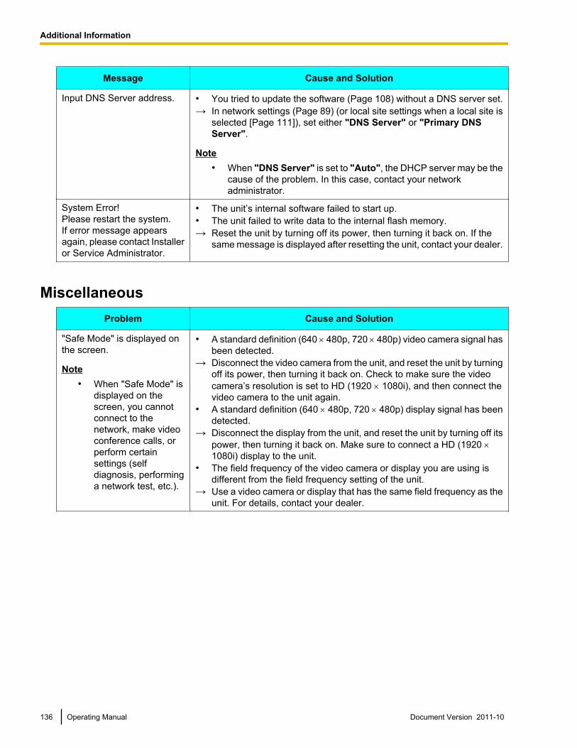
Message Cause and Solution
Input DNS Server address. • You tried to update the software (Page 108) without a DNS server set.→ In network settings (Page 89) (or local site settings when a local site is
selected [Page 111]), set either "DNS Server" or "Primary DNSServer".
Note• When "DNS Server" is set to "Auto", the DHCP server may be the
cause of the problem. In this case, contact your networkadministrator.
System Error!Please restart the system. If error message appearsagain, please contact Installeror Service Administrator.
• The unit’s internal software failed to start up.• The unit failed to write data to the internal flash memory.→ Reset the unit by turning off its power, then turning it back on. If the
same message is displayed after resetting the unit, contact your dealer.
MiscellaneousProblem Cause and Solution
"Safe Mode" is displayed onthe screen.
Note• When "Safe Mode" is
displayed on thescreen, you cannotconnect to thenetwork, make videoconference calls, orperform certainsettings (selfdiagnosis, performinga network test, etc.).
• A standard definition (640 ́ 480p, 720 ́ 480p) video camera signal hasbeen detected.
→ Disconnect the video camera from the unit, and reset the unit by turningoff its power, then turning it back on. Check to make sure the videocamera’s resolution is set to HD (1920 ´ 1080i), and then connect thevideo camera to the unit again.
• A standard definition (640 ´ 480p, 720 ´ 480p) display signal has beendetected.
→ Disconnect the display from the unit, and reset the unit by turning off itspower, then turning it back on. Make sure to connect a HD (1920 ´1080i) display to the unit.
• The field frequency of the video camera or display you are using isdifferent from the field frequency setting of the unit.
→ Use a video camera or display that has the same field frequency as theunit. For details, contact your dealer.
136 Operating Manual Document Version 2011-10
Additional Information
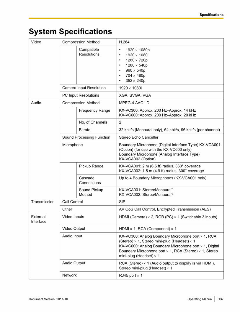
System SpecificationsVideo Compression Method H.264
CompatibleResolutions
• 1920 ´ 1080p• 1920 ´ 1080i• 1280 ´ 720p• 1280 ´ 540p• 960 ´ 540p• 704 ´ 480p• 352 ´ 240p
Camera Input Resolution 1920 ´ 1080i
PC Input Resolutions XGA, SVGA, VGA
Audio Compression Method MPEG-4 AAC LD
Frequency Range KX-VC300: Approx. 200 Hz–Approx. 14 kHzKX-VC600: Approx. 200 Hz–Approx. 20 kHz
No. of Channels 2
Bitrate 32 kbit/s (Monaural only), 64 kbit/s, 96 kbit/s (per channel)
Sound Processing Function Stereo Echo Canceller
Microphone Boundary Microphone (Digital Interface Type) KX-VCA001(Option) (for use with the KX-VC600 only)Boundary Microphone (Analog Interface Type)KX-VCA002 (Option)
Pickup Range KX-VCA001: 2 m (6.5 ft) radius, 360° coverageKX-VCA002: 1.5 m (4.9 ft) radius, 300° coverage
CascadeConnections
Up to 4 Boundary Microphones (KX-VCA001 only)
Sound PickupMethod
KX-VCA001: Stereo/Monaural*1KX-VCA002: Stereo/Monaural*2
Transmission Call Control SIP
Other AV QoS Call Control, Encrypted Transmission (AES)
ExternalInterface
Video Inputs HDMI (Camera) ´ 2, RGB (PC) ´ 1 (Switchable 3 inputs)
Video Output HDMI ´ 1, RCA (Component) ´ 1
Audio Input KX-VC300: Analog Boundary Microphone port ´ 1, RCA(Stereo) ´ 1, Stereo mini-plug (Headset) ´ 1KX-VC600: Analog Boundary Microphone port ´ 1, DigitalBoundary Microphone port ´ 1, RCA (Stereo) ´ 1, Stereomini-plug (Headset) ´ 1
Audio Output RCA (Stereo) ´ 1 (Audio output to display is via HDMI),Stereo mini-plug (Headset) ´ 1
Network RJ45 port ´ 1
Document Version 2011-10 Operating Manual 137
S
p
e
c
i
f
i
c
a
t
i
o
n
s
Specifications
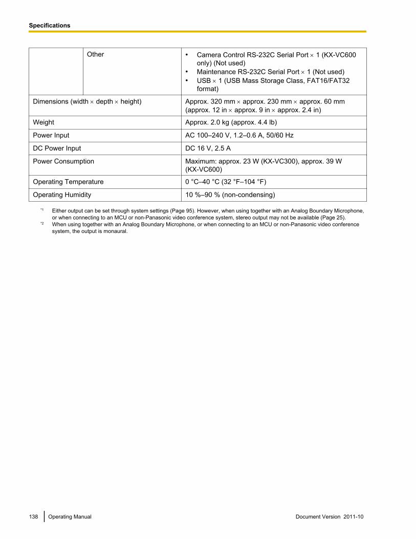
Other • Camera Control RS-232C Serial Port ´ 1 (KX-VC600only) (Not used)
• Maintenance RS-232C Serial Port ´ 1 (Not used)• USB ´ 1 (USB Mass Storage Class, FAT16/FAT32
format)
Dimensions (width ´ depth ´ height) Approx. 320 mm ´ approx. 230 mm ´ approx. 60 mm(approx. 12 in ´ approx. 9 in ´ approx. 2.4 in)
Weight Approx. 2.0 kg (approx. 4.4 lb)
Power Input AC 100–240 V, 1.2–0.6 A, 50/60 Hz
DC Power Input DC 16 V, 2.5 A
Power Consumption Maximum: approx. 23 W (KX-VC300), approx. 39 W(KX-VC600)
Operating Temperature 0 °C–40 °C (32 °F–104 °F)
Operating Humidity 10 %–90 % (non-condensing)
*1 Either output can be set through system settings (Page 95). However, when using together with an Analog Boundary Microphone,or when connecting to an MCU or non-Panasonic video conference system, stereo output may not be available (Page 25).
*2 When using together with an Analog Boundary Microphone, or when connecting to an MCU or non-Panasonic video conferencesystem, the output is monaural.
138 Operating Manual Document Version 2011-10
Specifications
IndexAActivating Enhanced Features 83, 107
Enabling Multiple-Party Video Conference Calls(KX-VC300 only) 83Enabling the Sending of Images in Full HD Resolution(KX-VC300 only) 83
Activation Key 83Activation Key Card for 1080 Full HD (KX-VCS401) 83Activation Key Card for 4-Point Connection(KX-VCS301) 83Administrator Password, setting 102Amplifier/Speaker 28Answering a Video Conference Call 47Answering, Automatic 47Answering, Manual 47
BBatteries, changing (remote control) 121Boundary Microphone 22
Boundary Microphone (Analog Interface Type) 22, 27Boundary Microphone (Digital Interface Type) 22, 25
Buttons Power 18Remote Control 21
CCalling by Entering an Address Directly 41Calling from the Call History 44Calling from the Contact List 39Calling using Speed Dial 36Cleaning the unit 122Computer Screen, viewing 69Confirming the MPR ID 107Connecting to a Non-Panasonic Video ConferenceSystem 48Connecting to an MCU 49Connection
Amplifier/Active Speaker 28Connection Status, viewing 80Connection, setting 90Contacts, adding 84Contacts, deleting 86Contacts, editing 85Controlling a PTZ Camera 59
DDate and Time, setting 89
EEnabling Multiple-Party Video Conference Calls (KX-VC300only) 83Enabling the Sending of Images in Full HD Resolution(KX-VC300 only) 83Encryption, setting 103
FFor Your Safety 10
HHeadset 28
IInputting Letters and Numbers 116
KKX-VCS301 (Activation Key Card for 4-PointConnection) 83KX-VCS401 (Activation Key Card for 1080 Full HD) 83
LLanguage, setting 98LED Patterns 23Local Site, setting 111
MMaking a Video Conference Call 36Making SIP Settings 105MIC Position, setting (KX-VC600 only) 94Muting the Microphone 65
NNetwork Test, performing 99Network, setting 89Noise reduction (KX-VC600 only) 67
OOptional Accessory 22
PPart Names and Usage 18Ports, Main Unit 19Power button 18Privacy 15Protecting Information 15
RRegistering the Registration Key 107Remote Control 21Remote Control, setting 96Remote Maintenance, performing 99, 101Right of Publicity 15
SScreen Display 31Screen Layout, changing (2-party call) 51Screen Layout, changing (3-party call) 53Screen Layout, changing (4-party call) 56Screen Standby Mode 23Screen Standby, setting 93Security 15
Document Version 2011-10 Operating Manual 139
Index
Self Diagnosis, performing 100Software Update, setting 104, 105Sound, setting 93Specifications, system 137Sub Video Camera, viewing 76System Initialization, performing 106
TTone, Adjusting 68Troubleshooting 123
UUnit Information, viewing 81, 99Unit Name, setting 88
VVolume, adjusting 64
140 Operating Manual Document Version 2011-10
Index

Document Version 2011-10 Operating Manual 141
Notes
carton.
DO NOT
arranty.
fices. They are NOT
When you ship the productCarefully pack and send it prepaid, adequately insured and preferably in the original
Attach a postage-paid letter, detailing the symptom to the outside of the carton.
send the product to the Executive or Regional Sales of
equipped to make repairs.
Product serviceFor product service, ship the product to the address listed in the Limited W
Consult your authorized Panasonic dealer for detailed instructions.
Copyright:
This material is copyrighted by Panasonic System Networks Co., Ltd., and may be reproduced for internal
use only. All other reproduction, in whole or in part, is prohibited without the written consent of Panasonic
System Networks Co., Ltd.
© Panasonic System Networks Co., Ltd. 2011
PNQX3803YA DD0411AK1101
Web Site: http://www.panasonic.ca
5770 Ambler Drive, Mississauga, Ontario, L4W 2T3
One Panasonic Way, Secaucus, New Jersey 07094
Web Site: http://www.panasonic.com/bts
1-62, 4-chome, Minoshima, Hakata-ku, Fukuoka 812-8531, Japan
Web Site: http://www.panasonic.net/