Embed Size (px)
DESCRIPTION
transmision zx50 kymco
Citation preview
8. KICK STARTER/DRIVE PULLEY/CLUTCH/DRIVEN PULLEY
8-0
ZX / SCOUT 50
8 __________________________________________________________________________________
__________________________________________________________________________________
__________________________________________________________________________________
__________________________________________________________________________________
__________________________________________________________________________________
KICK STARTER/DRIVE PULLEY/CLUTCH/DRIVEN PULLEY
__________________________________________________________________________________
SERVICE INFORMATION........................................................ 8- 2
TROUBLESHOOTING.............................................................. 8- 2
KICK STARTER....................................................................... 8- 3
DRIVE BELT ........................................................................... 8- 7
DRIVE PULLEY....................................................................... 8- 9
STARTER PINION ................................................................... 8-11
CLUTCH/DRIVEN PULLEY ..................................................... 8-12
8
8. KICK STARTER/DRIVE PULLEY/CLUTCH/DRIVEN PULLEY
8-1
ZX / SCOUT 50
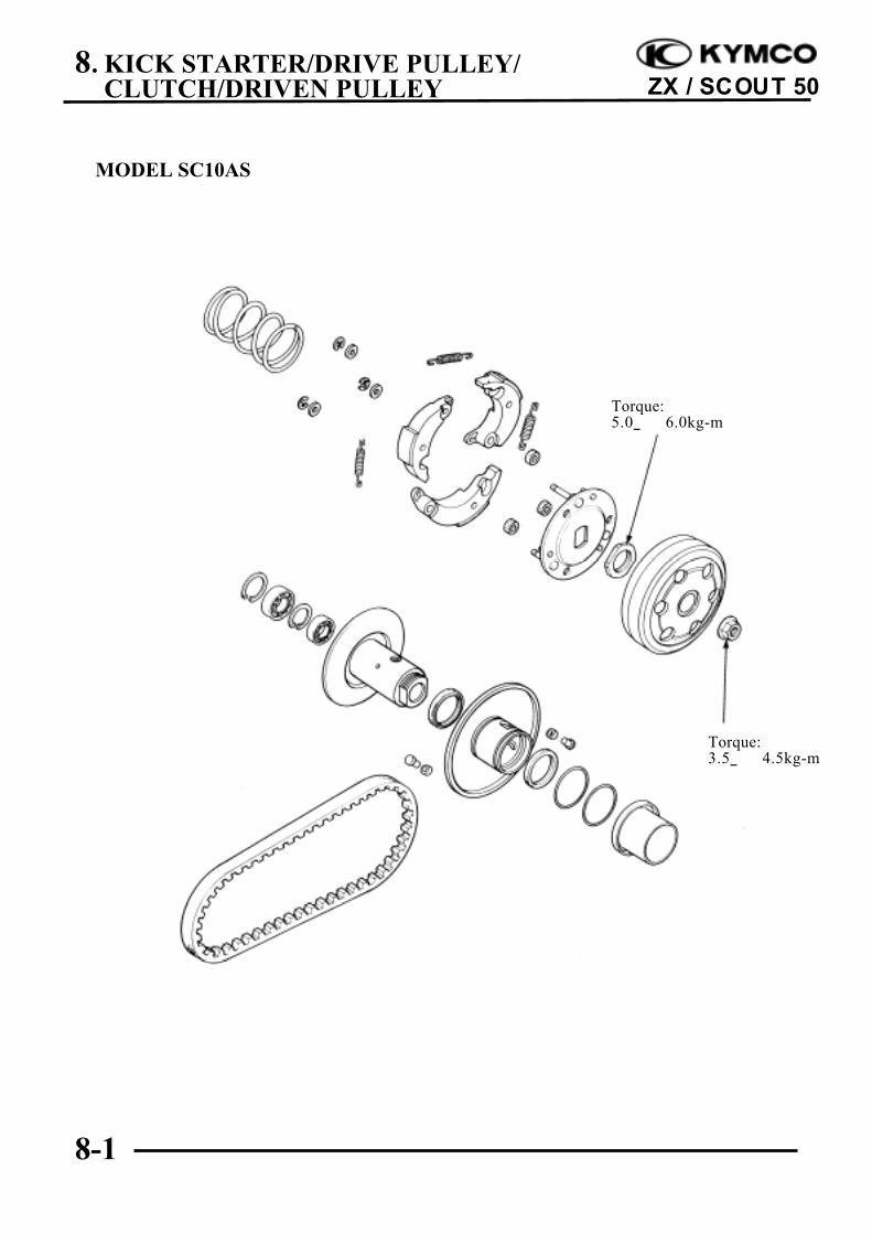
MODEL SC10AS
Torque:3.5_ 4.5kg-m
Torque:5.0_ 6.0kg-m
8. KICK STARTER/DRIVE PULLEY/CLUTCH/DRIVEN PULLEY
8-2
ZX / SCOUT 50
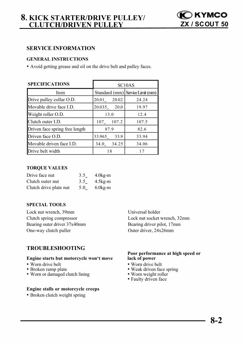
SERVICE INFORMATION
GENERAL INSTRUCTIONS
• Avoid getting grease and oil on the drive belt and pulley faces.
SPECIFICATIONS SC10AS
Item Standard (mm) Service Limit (mm)
Drive pulley collar O.D. 20.01_ 20.02
5
24.24
Movable drive face I.D. 20.035_ 20.0
85
19.97
Weight roller O.D. 13.0 12.4
Clutch outer I.D. 107_ 107.2 107.5
Driven face spring free length 87.9 82.6
Driven face O.D. 33.965_ 33.9
85
33.94
Movable driven face I.D. 34.0_ 34.25 34.06
Drive belt width 18 17
TORQUE VALUES
Drive face nut 3.5_ 4.0kg-mClutch outer nut 3.5_ 4.5kg-mClutch drive plate nut 5.0_ 6.0kg-m
SPECIAL TOOLS
Lock nut wrench, 39mm Universal holderClutch spring compressor Lock nut socket wrench, 32mmBearing outer driver 37x40mm Bearing driver pilot, 17mmOne-way clutch puller Outer driver, 24x26mm
TROUBLESHOOTINGPoor performance at high speed or
Engine starts but motorcycle won‘t move lack of power• Worn drive belt • Worn drive belt• Broken ramp plate • Weak driven face spring• Worn or damaged clutch lining • Worn weight roller
• Faulty driven face
Engine stalls or motorcycle creeps• Broken clutch weight spring
8. KICK STARTER/DRIVE PULLEY/CLUTCH/DRIVEN PULLEY
8-3
ZX / SCOUT 50
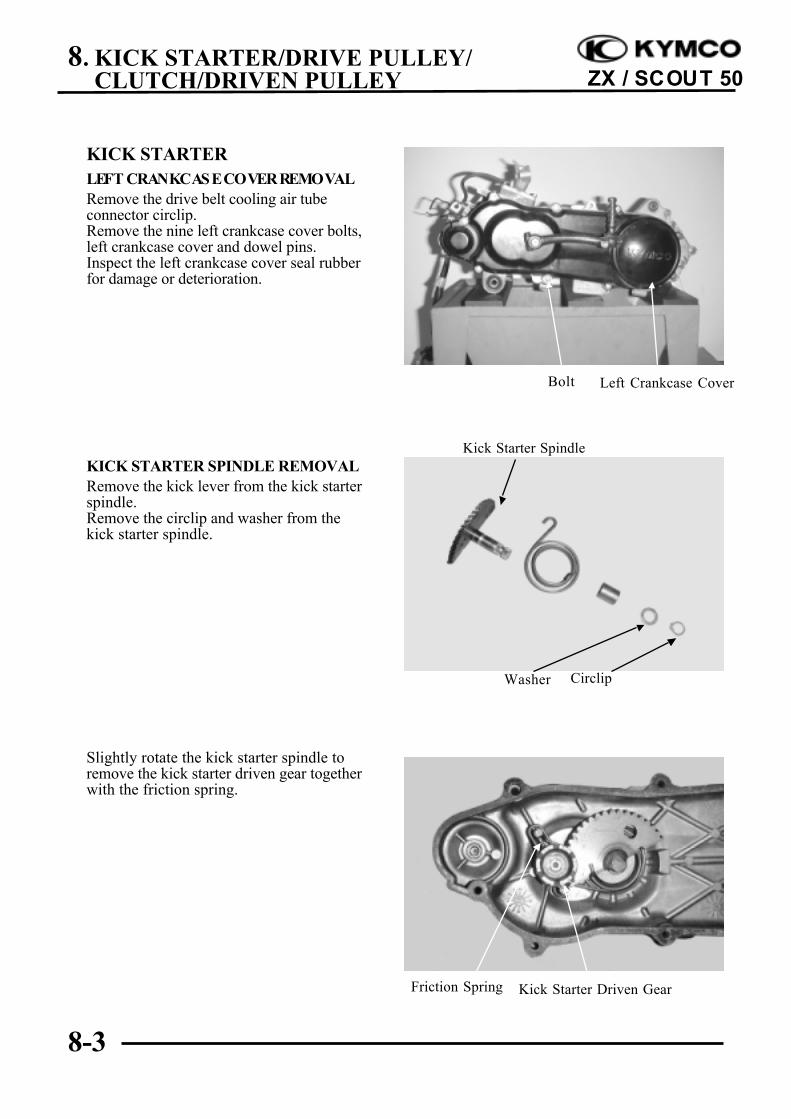
KICK STARTERLEFT CRANKCASE COVER REMOVALRemove the drive belt cooling air tubeconnector circlip.Remove the nine left crankcase cover bolts,left crankcase cover and dowel pins.Inspect the left crankcase cover seal rubberfor damage or deterioration.
KICK STARTER SPINDLE REMOVALRemove the kick lever from the kick starterspindle.Remove the circlip and washer from thekick starter spindle.
Slightly rotate the kick starter spindle toremove the kick starter driven gear togetherwith the friction spring.
Kick Starter Spindle
Left Crankcase CoverBolt
Friction Spring Kick Starter Driven Gear
Washer Circlip
8. KICK STARTER/DRIVE PULLEY/CLUTCH/DRIVEN PULLEY
8-4
ZX / SCOUT 50
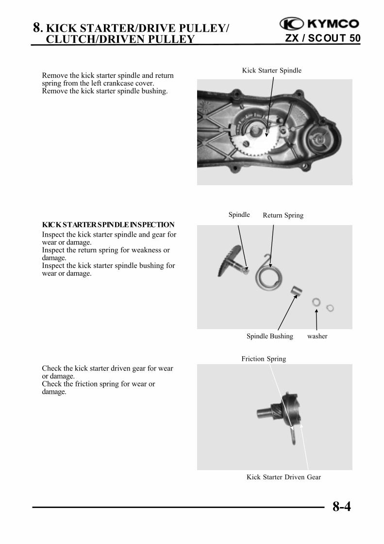
Remove the kick starter spindle and returnspring from the left crankcase cover.Remove the kick starter spindle bushing.
KICK STARTER SPINDLE INSPECTIONInspect the kick starter spindle and gear forwear or damage.Inspect the return spring for weakness ordamage.Inspect the kick starter spindle bushing forwear or damage.
Check the kick starter driven gear for wearor damage.Check the friction spring for wear ordamage.
Kick Starter Spindle
Spindle
Friction Spring
Kick Starter Driven Gear
washerSpindle Bushing
Return Spring
8. KICK STARTER/DRIVE PULLEY/CLUTCH/DRIVEN PULLEY
8-5
ZX / SCOUT 50
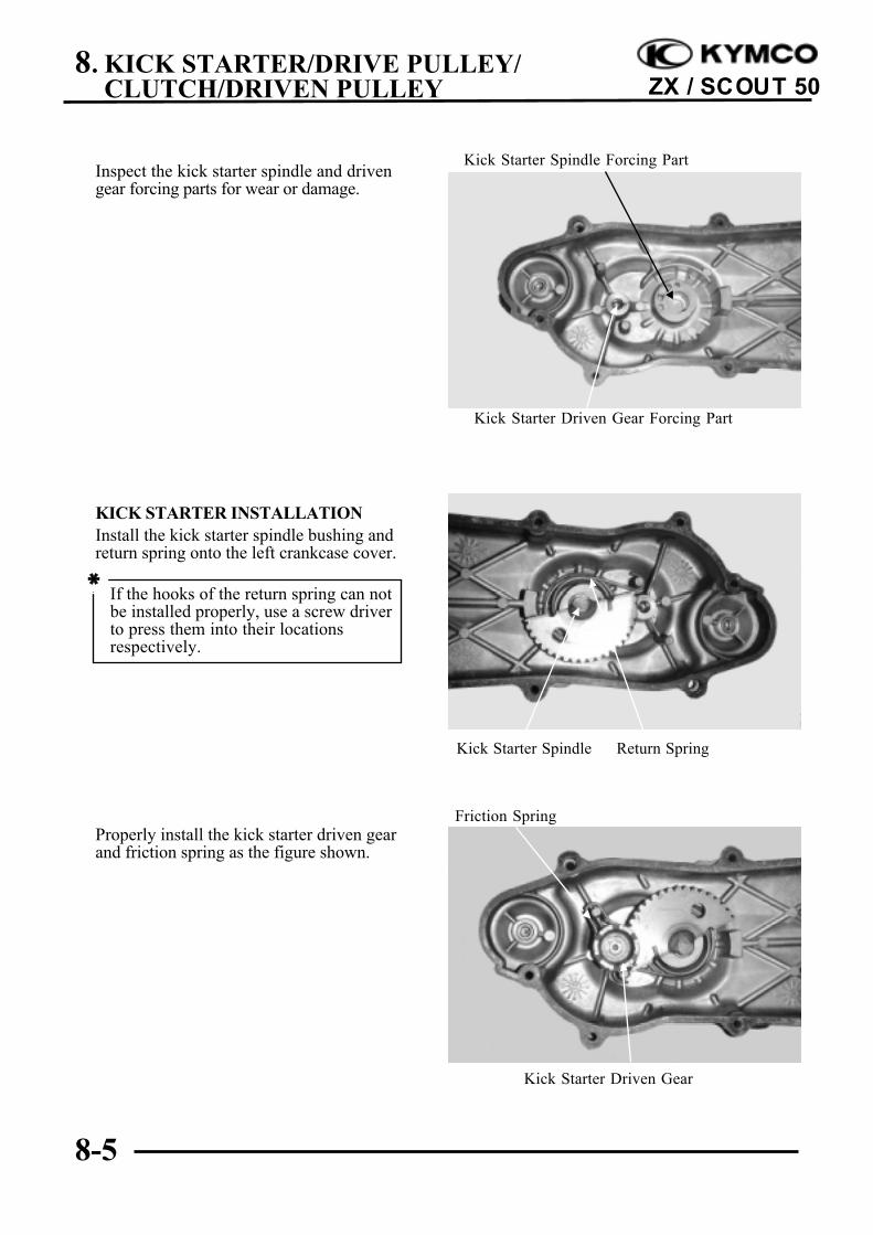
Inspect the kick starter spindle and drivengear forcing parts for wear or damage.
KICK STARTER INSTALLATIONInstall the kick starter spindle bushing andreturn spring onto the left crankcase cover.
Properly install the kick starter driven gearand friction spring as the figure shown.
If the hooks of the return spring can notbe installed properly, use a screw driverto press them into their locationsrespectively.
*
Kick Starter Spindle Forcing Part
Friction Spring
Kick Starter Driven Gear
Return SpringKick Starter Spindle
Kick Starter Driven Gear Forcing Part
8. KICK STARTER/DRIVE PULLEY/CLUTCH/DRIVEN PULLEY
8-6
ZX / SCOUT 50
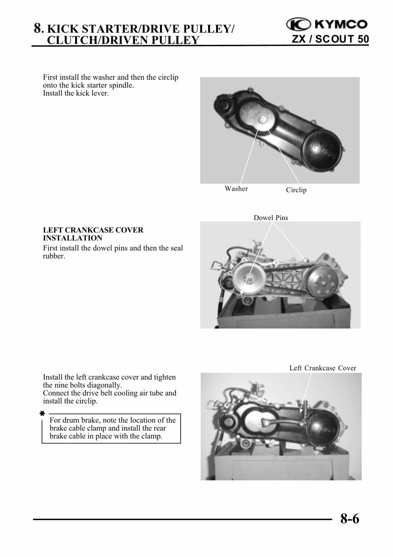
First install the washer and then the circliponto the kick starter spindle.Install the kick lever.
LEFT CRANKCASE COVERINSTALLATIONFirst install the dowel pins and then the sealrubber.
Install the left crankcase cover and tightenthe nine bolts diagonally.Connect the drive belt cooling air tube andinstall the circlip.
Left Crankcase Cover
Dowel Pins
Washer Circlip
For drum brake, note the location of thebrake cable clamp and install the rearbrake cable in place with the clamp.
*
8. KICK STARTER/DRIVE PULLEY/CLUTCH/DRIVEN PULLEY
8-7
ZX / SCOUT 50
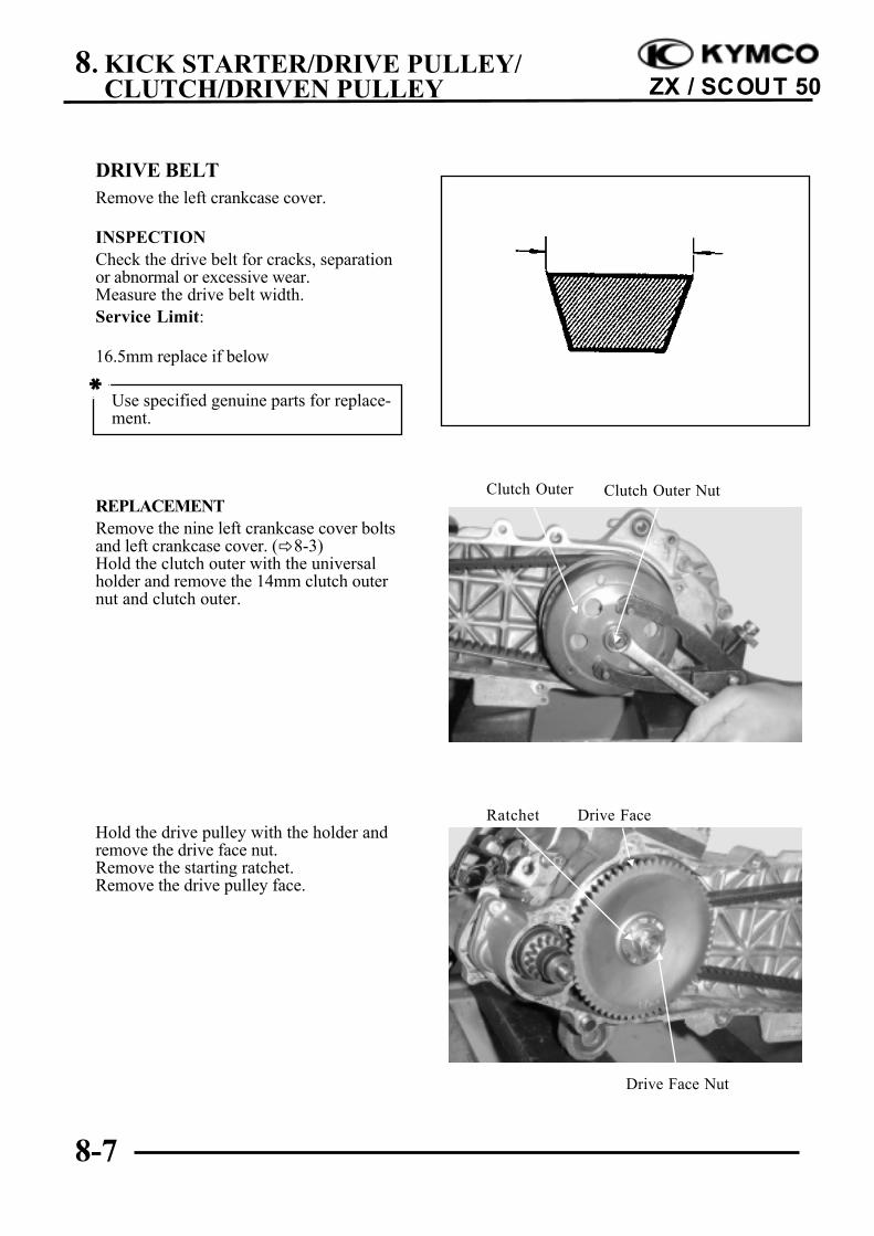
DRIVE BELTRemove the left crankcase cover.
INSPECTIONCheck the drive belt for cracks, separationor abnormal or excessive wear.Measure the drive belt width.Service Limit:
16.5mm replace if below
REPLACEMENTRemove the nine left crankcase cover boltsand left crankcase cover. (!8-3)Hold the clutch outer with the universalholder and remove the 14mm clutch outernut and clutch outer.
Hold the drive pulley with the holder andremove the drive face nut.Remove the starting ratchet.Remove the drive pulley face.
Use specified genuine parts for replace-ment.
*
Clutch Outer
Drive Face Nut
Drive Face
Clutch Outer Nut
Ratchet
8. KICK STARTER/DRIVE PULLEY/CLUTCH/DRIVEN PULLEY
8-8
ZX / SCOUT 50
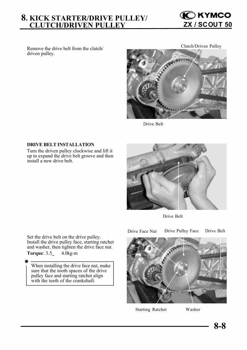
Remove the drive belt from the clutch/driven pulley.
DRIVE BELT INSTALLATIONTurn the driven pulley clockwise and lift itup to expand the drive belt groove and theninstall a new drive belt.
Set the drive belt on the drive pulley.Install the drive pulley face, starting ratchetand washer, then tighten the drive face nut.Torque: 3.5_ 4.0kg-m
Clutch/Driven Pulley
Drive Belt
Drive Belt
Drive Pulley Face
Washer
Drive Belt
Starting Ratchet
Drive Face Nut
When installing the drive face nut, makesure that the tooth spaces of the drivepulley face and starting ratchet alignwith the teeth of the crankshaft.
*
8. KICK STARTER/DRIVE PULLEY/CLUTCH/DRIVEN PULLEY
8-9
ZX / SCOUT 50
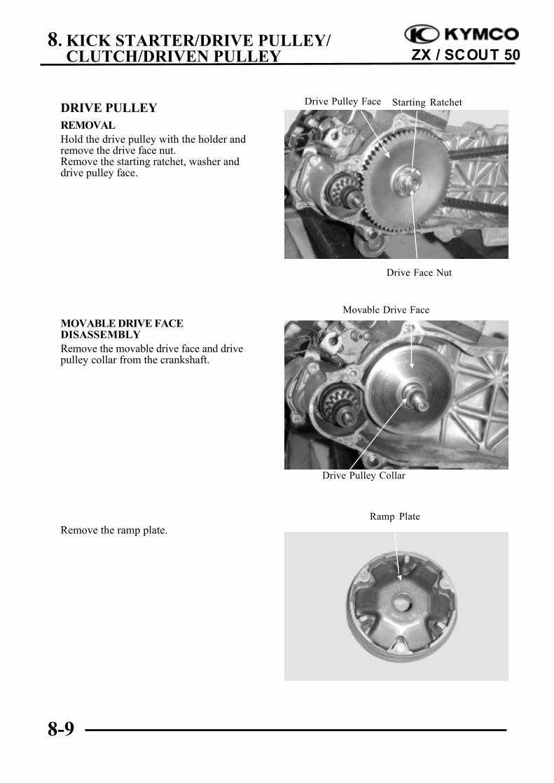
DRIVE PULLEYREMOVALHold the drive pulley with the holder andremove the drive face nut.Remove the starting ratchet, washer anddrive pulley face.
MOVABLE DRIVE FACEDISASSEMBLYRemove the movable drive face and drivepulley collar from the crankshaft.
Remove the ramp plate.
Movable Drive Face
Ramp Plate
Drive Face Nut
Starting RatchetDrive Pulley Face
Drive Pulley Collar
8. KICK STARTER/DRIVE PULLEY/CLUTCH/DRIVEN PULLEY
8-10
ZX / SCOUT 50
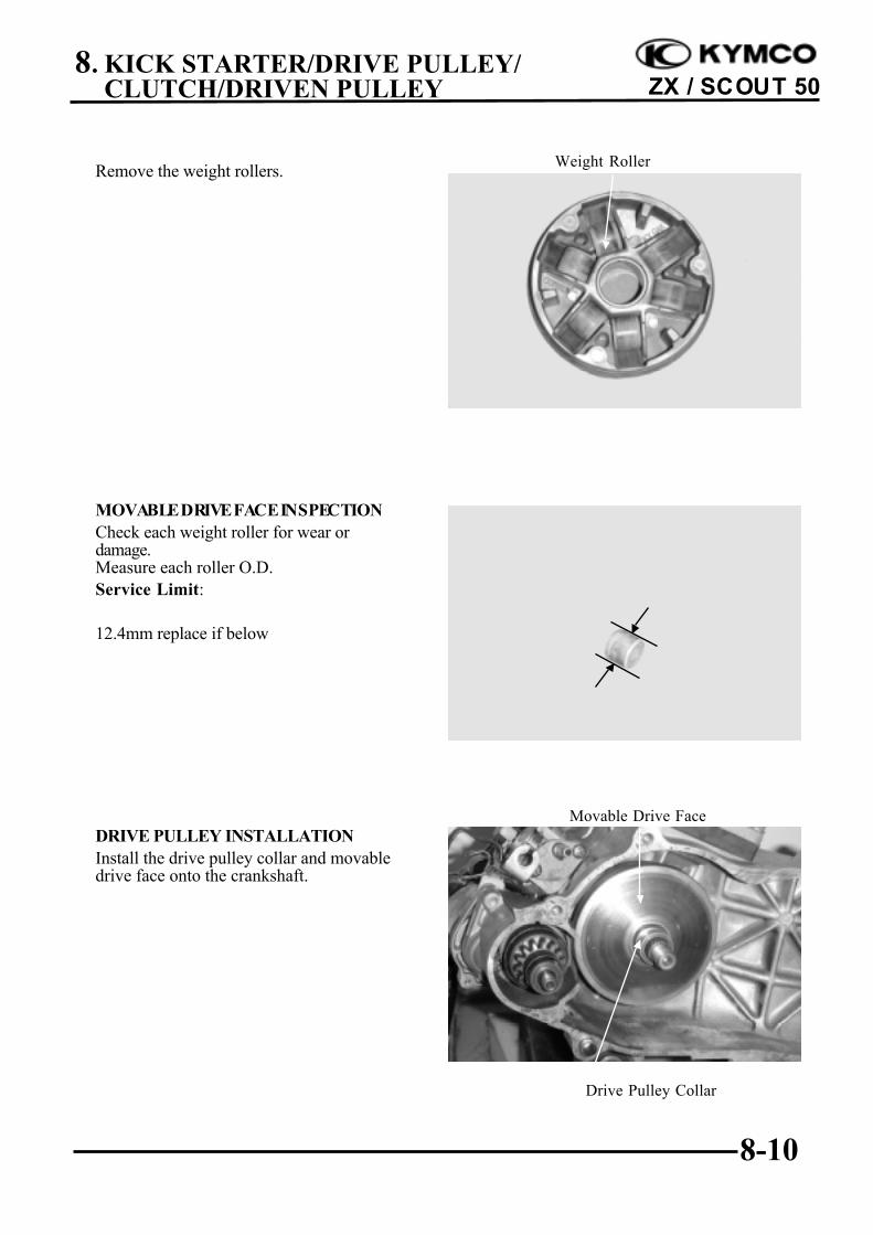
Remove the weight rollers.
MOVABLE DRIVE FACE INSPECTIONCheck each weight roller for wear ordamage.Measure each roller O.D.Service Limit:
12.4mm replace if below
DRIVE PULLEY INSTALLATIONInstall the drive pulley collar and movabledrive face onto the crankshaft.
Weight Roller
Movable Drive Face
Drive Pulley Collar
8. KICK STARTER/DRIVE PULLEY/CLUTCH/DRIVEN PULLEY
8-11
ZX / SCOUT 50
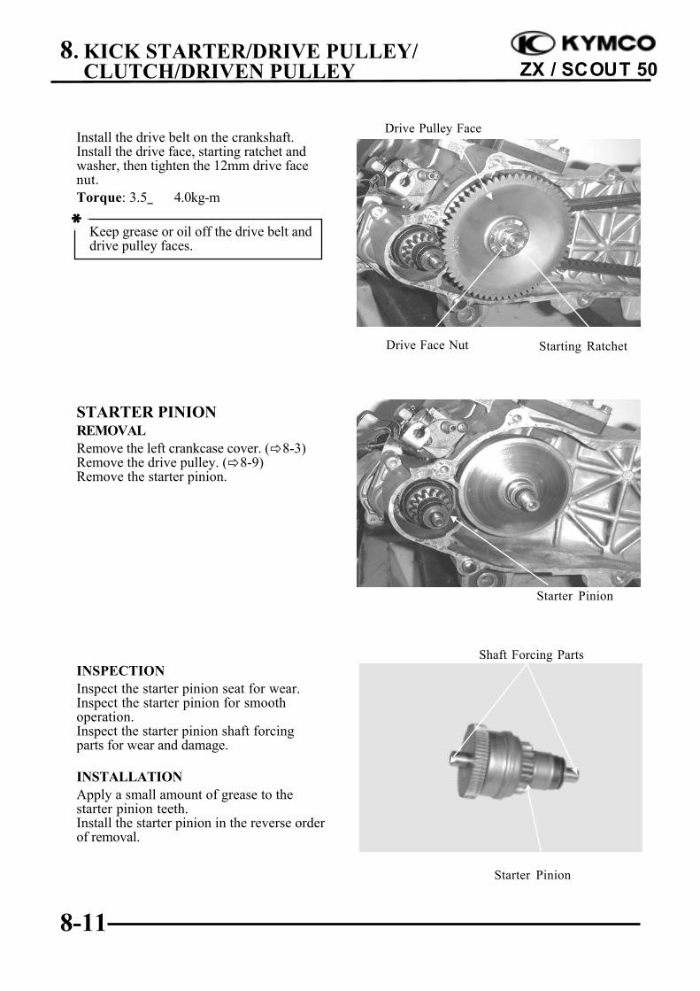
Install the drive belt on the crankshaft.Install the drive face, starting ratchet andwasher, then tighten the 12mm drive facenut.Torque: 3.5_ 4.0kg-m
STARTER PINIONREMOVALRemove the left crankcase cover. (!8-3)Remove the drive pulley. (!8-9)Remove the starter pinion.
INSPECTIONInspect the starter pinion seat for wear.Inspect the starter pinion for smoothoperation.Inspect the starter pinion shaft forcingparts for wear and damage.
INSTALLATIONApply a small amount of grease to thestarter pinion teeth.Install the starter pinion in the reverse orderof removal.
Keep grease or oil off the drive belt anddrive pulley faces.
*
Drive Face Nut Starting Ratchet
Drive Pulley Face
Starter Pinion
Shaft Forcing Parts
Starter Pinion
8. KICK STARTER/DRIVE PULLEY/CLUTCH/DRIVEN PULLEY
8-12
ZX / SCOUT 50
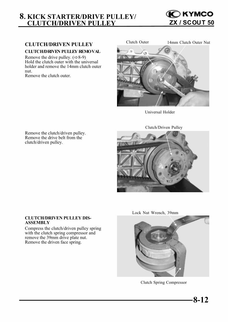
CLUTCH/DRIVEN PULLEYCLUTCH/DRIVEN PULLEY REMOVALRemove the drive pulley. (!8-9)Hold the clutch outer with the universalholder and remove the 14mm clutch outernut.Remove the clutch outer.
Remove the clutch/driven pulley.Remove the drive belt from theclutch/driven pulley.
CLUTCH/DRIVEN PULLEY DIS-ASSEMBLYCompress the clutch/driven pulley springwith the clutch spring compressor andremove the 39mm drive plate nut.Remove the driven face spring.
Clutch/Driven Pulley
Universal Holder
Clutch Outer 14mm Clutch Outer Nut
Clutch Spring Compressor
Lock Nut Wrench, 39mm
8. KICK STARTER/DRIVE PULLEY/CLUTCH/DRIVEN PULLEY
8-13
ZX / SCOUT 50
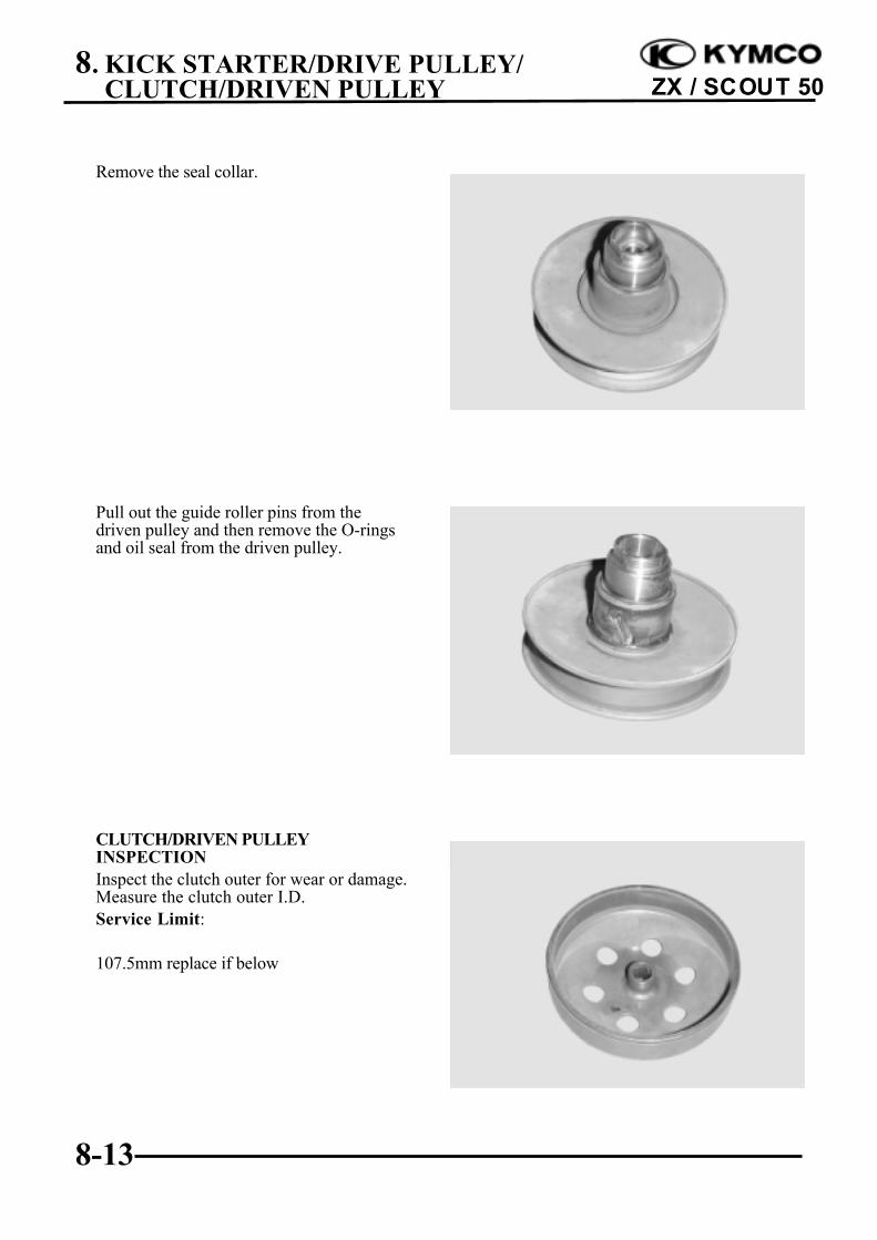
Remove the seal collar.
Pull out the guide roller pins from thedriven pulley and then remove the O-ringsand oil seal from the driven pulley.
CLUTCH/DRIVEN PULLEYINSPECTIONInspect the clutch outer for wear or damage.Measure the clutch outer I.D.Service Limit:
107.5mm replace if below
8. KICK STARTER/DRIVE PULLEY/CLUTCH/DRIVEN PULLEY
8-14
ZX / SCOUT 50
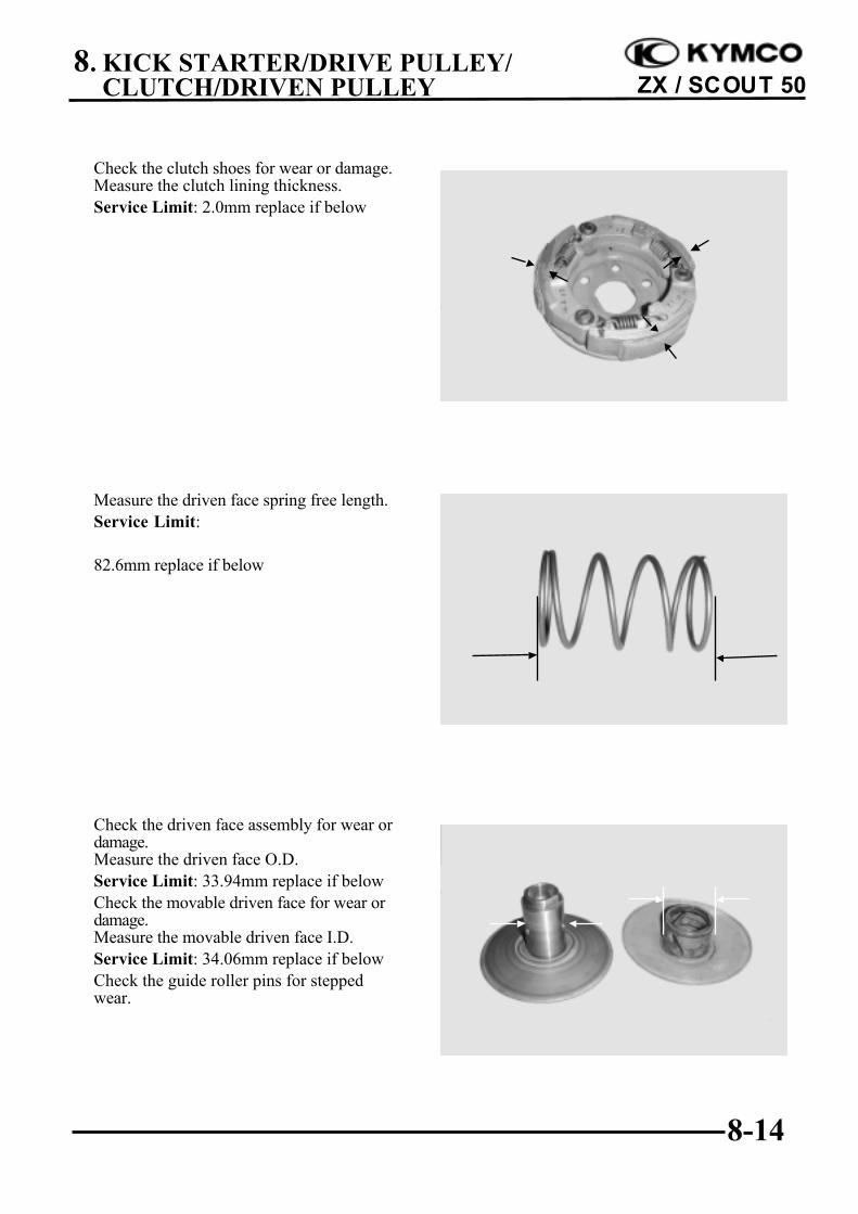
Check the clutch shoes for wear or damage.Measure the clutch lining thickness.Service Limit: 2.0mm replace if below
Measure the driven face spring free length.Service Limit:
82.6mm replace if below
Check the driven face assembly for wear ordamage.Measure the driven face O.D.Service Limit: 33.94mm replace if belowCheck the movable driven face for wear ordamage.Measure the movable driven face I.D.Service Limit: 34.06mm replace if belowCheck the guide roller pins for steppedwear.
8. KICK STARTER/DRIVE PULLEY/CLUTCH/DRIVEN PULLEY
8-15
ZX / SCOUT 50
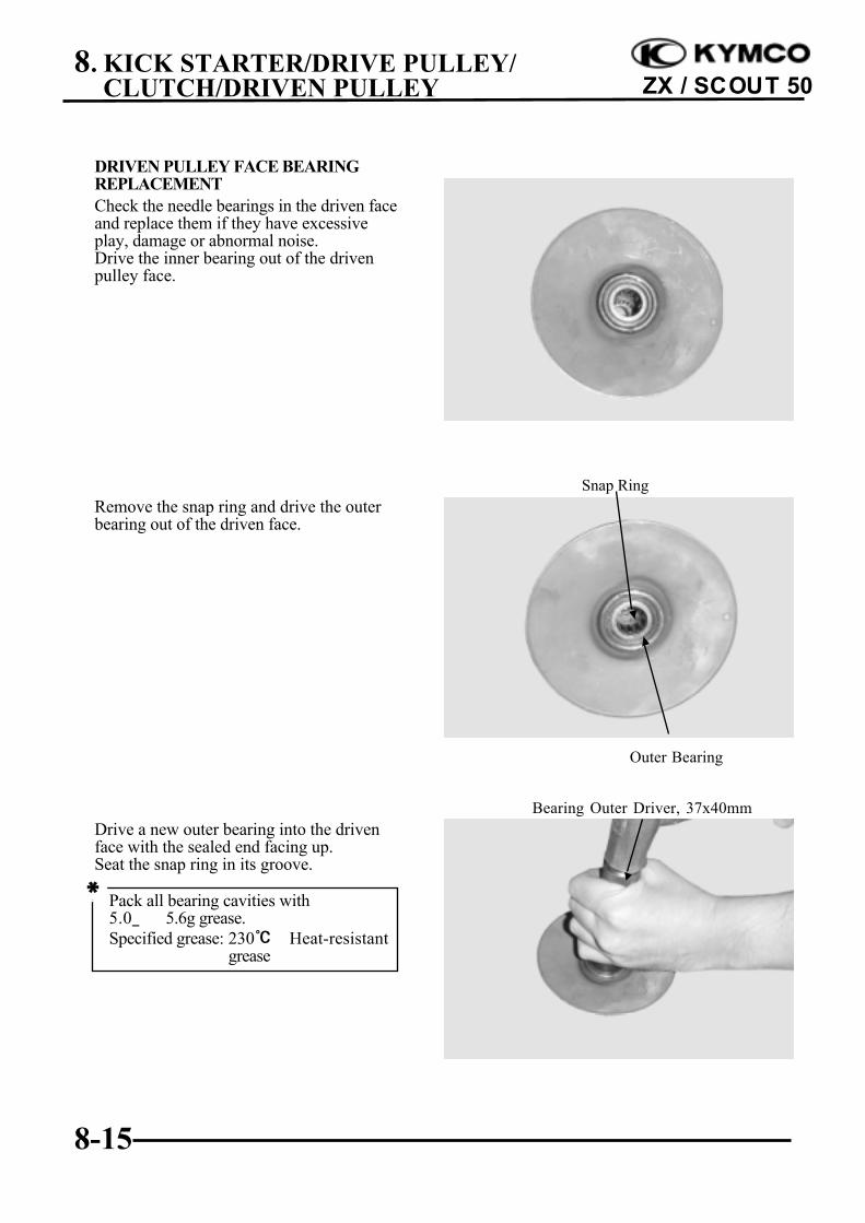
DRIVEN PULLEY FACE BEARINGREPLACEMENTCheck the needle bearings in the driven faceand replace them if they have excessiveplay, damage or abnormal noise.Drive the inner bearing out of the drivenpulley face.
Remove the snap ring and drive the outerbearing out of the driven face.
Drive a new outer bearing into the drivenface with the sealed end facing up.Seat the snap ring in its groove.
Snap Ring
Bearing Outer Driver, 37x40mm
Outer Bearing
Pack all bearing cavities with5.0_ 5.6g grease.Specified grease: 230℃ Heat-resistant
grease
*
8. KICK STARTER/DRIVE PULLEY/CLUTCH/DRIVEN PULLEY
8-16
ZX / SCOUT 50
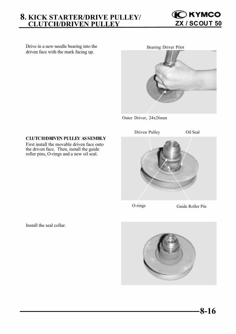
Drive in a new needle bearing into thedriven face with the mark facing up.
CLUTCH/DRIVEN PULLEY ASSEMBLYFirst install the movable driven face ontothe driven face. Then, install the guideroller pins, O-rings and a new oil seal.
Install the seal collar.
Oil Seal
O-rings Guide Roller Pin
Driven Pulley
Bearing Driver Pilot
Outer Driver, 24x26mm
8. KICK STARTER/DRIVE PULLEY/CLUTCH/DRIVEN PULLEY
8-17
ZX / SCOUT 50
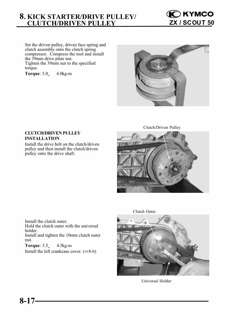
Set the driven pulley, driven face spring andclutch assembly onto the clutch springcompressor. Compress the tool and installthe 39mm drive plate nut.Tighten the 39mm nut to the specifiedtorque.Torque: 5.0_ 6.0kg-m
CLUTCH/DRIVEN PULLEYINSTALLATIONInstall the drive belt on the clutch/drivenpulley and then install the clutch/drivenpulley onto the drive shaft.
Install the clutch outer.Hold the clutch outer with the universalholder.Install and tighten the 10mm clutch outernut.Torque: 3.5_ 4.5kg-mInstall the left crankcase cover. (!8-6)
Universal Holder
Clutch Outer
Clutch/Driven Pulley