Embed Size (px)
Citation preview
DAFTAR PUSTAKA
Alaitz Gonzalez. 2007. Machine Tool Utilisation Phase: Costs and
Environmental Impacts with a Life Cycle View Master of Science
Thesis Stockholm,Presented At Industrial Ecology Royal Institute Of
Technology.
Aqapiou, John S dan Stephenson, David A. 2006. Metal Cutting Theory And
Practice. Broken Sound Parkway Nw. Boca Raton. USA.
Ardraviz, Karakteristik Sifat Besi Tuang Cor Kelabu. Online.
https://ardra.biz/sain-teknologi/metalurgi/besi-cor-cast-
iron/karakteristik-sifat-besi-tuang-cor-kelabu-gray-cast-iron/
Braucke, 2004. Establishment of a Database for Tool Life Performance.
School of Engineering and Science Swinburne University of
Technology, Australia.
D Clough, S Fletcher, A P Longstaff And P Willoughby. 2012, Thermal
Analysis For Condition Monitoring Of Machine Tool Spindles,
University Of Huddersfield, Uk.
Franke, JӦrg E. 2011. Experimental Evaluation of the Thermal Machine
Tool Behavior for Model Updating, Institute for Manufacturing
Automation and Production Systems, Germany.
Gutowski, T, G., Dahmus, J. B., Thiriez, A. 2006. Electrical Energy
Requirements for Manufacturing Processes. Leuven, Belgium, pp.
623-627. Proceedings of the 13th CIRP Conference on Life Cycle
Engineering, ed. By Duflou, J. et al.
Helmi A. Youssef, Hassan El-Hofy. 2008. Machining technology : machine
tools and operations. Broken Sound Parkway NW, Suite 300 Boca
Raton, FL 33487-2742 .CRC Press Taylor & Francis Group 6000.
Hermann, C., Bergmann, L., Thiede, S., Zein, A. 2007. Framework for
Integrated Analysis of Production Systems; in Proceedings of the
14th CIRP Conference on Life Cycle Engineering, ed. by Takata, S.,
Umeda, Y., Tokyo, Japan, Springer, London, pp. 195-200.
Huda, Muhammad. 2010, Pengenalan Pola Citra Termografi Pada
Pemantauan Kondisi Mesin Dengan Metode Pengolahan Citra
Digital, Universitas Diponegoro, Semarang.
Kalpakjian, Serope. 1992. Manufacturing Engineering and Technology
2nd Edition. Addison Publishing Companya Inc. California.
Kalla, 2009, Unit Process Life Cycle Inventory for Product Manufacturing
Operations, in: Proceedings of the ASME International Manufacturing
Science and Engineering Conference, 2009.
Overcash M,. Twomey J., Kalla D,. Unit Process Life Cycle Inventory for
Product Manufacturing Operations, in: Proceedings of the ASME
International Manufacturing Science and Engineering Conference,
2009.
Rajemi. Mohamad Farizal. 2010. Energy Analysis in Turning and Milling.
A thesis submitted to The University of Mancheste for the degree of
Doctor of Philosophy in the Faculty of Engineering and Physical
Sciences. School of Mechanical, Aerospace and Civil.
Rajender Singh. 2006. Introduction to Basic Manufacturing Processes
and Workshop Technology. Ansari Road, Daryaganj, New Delhi –
110002. Publishing For One World New Age International (P) Limited,
Publishers 4835/24
Ravel/Bfk. 2000 N. N. Typischer Energiefluss einer guten Produktions
maschine. RAVEL/BFK, 724.397.12.54 D. Available from
http://www.energie.ch/themen/ industrie/infel/maschinen.htm
Rochim, 1993. Jenis Mesin Frais dan Pahat Frais. Online.
www.slideshere.net/mesin-frais
Skoczynski, 2013. Poland. Assesment of Energy Consumption by
Machine Tools. Wroclaw University Of Technology, Faculty Of
Mechanical Engineering, Institute Of Production Engineering And
Automation, Wybrzeze Wyspianskiego 27, Wroclaw.
Waclaw Skoczynski, Janusz Maczka, Zbigniew Wasiak, Andrzej Roszkowski,
Pawel Pres. 2013. Poland. Assesment of Energy Consumption by
Machine Tools. wroclaw university of technology, faculty of
mechanical engineering, institute of production engineering and
automation, wybrzeze wyspianskiego 27, wroclaw.
Widarto, 2008. Teknik Pemesinan . Jakarta :Direktorat Pembinaan
Sekolah Menengah Kejuruan.

L A M P I R A N
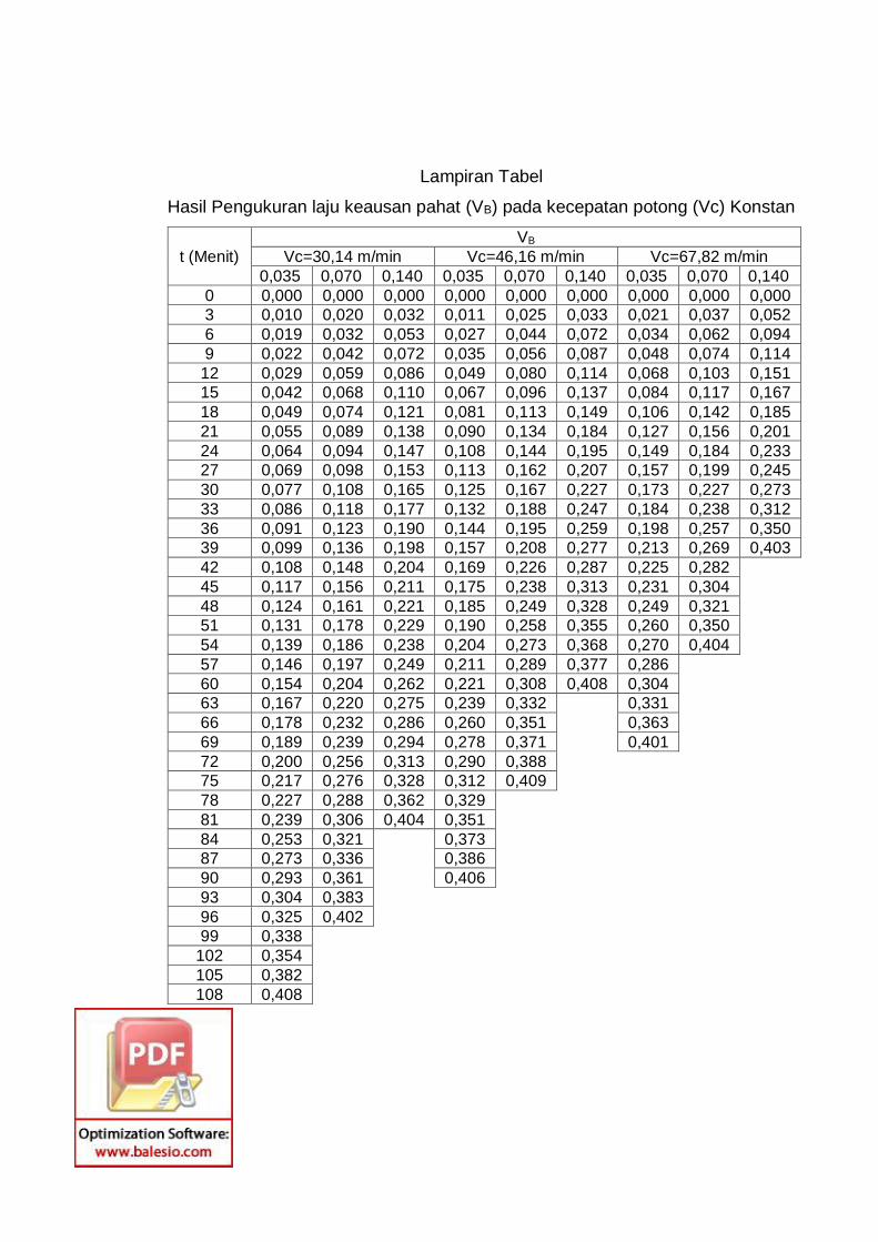
Lampiran Tabel
Hasil Pengukuran laju keausan pahat (VB) pada kecepatan potong (Vc) Konstan
t (Menit)
VB
Vc=30,14 m/min Vc=46,16 m/min Vc=67,82 m/min
0,035 0,070 0,140 0,035 0,070 0,140 0,035 0,070 0,140
0 0,000 0,000 0,000 0,000 0,000 0,000 0,000 0,000 0,000
3 0,010 0,020 0,032 0,011 0,025 0,033 0,021 0,037 0,052
6 0,019 0,032 0,053 0,027 0,044 0,072 0,034 0,062 0,094
9 0,022 0,042 0,072 0,035 0,056 0,087 0,048 0,074 0,114
12 0,029 0,059 0,086 0,049 0,080 0,114 0,068 0,103 0,151
15 0,042 0,068 0,110 0,067 0,096 0,137 0,084 0,117 0,167
18 0,049 0,074 0,121 0,081 0,113 0,149 0,106 0,142 0,185
21 0,055 0,089 0,138 0,090 0,134 0,184 0,127 0,156 0,201
24 0,064 0,094 0,147 0,108 0,144 0,195 0,149 0,184 0,233
27 0,069 0,098 0,153 0,113 0,162 0,207 0,157 0,199 0,245
30 0,077 0,108 0,165 0,125 0,167 0,227 0,173 0,227 0,273
33 0,086 0,118 0,177 0,132 0,188 0,247 0,184 0,238 0,312
36 0,091 0,123 0,190 0,144 0,195 0,259 0,198 0,257 0,350
39 0,099 0,136 0,198 0,157 0,208 0,277 0,213 0,269 0,403
42 0,108 0,148 0,204 0,169 0,226 0,287 0,225 0,282
45 0,117 0,156 0,211 0,175 0,238 0,313 0,231 0,304
48 0,124 0,161 0,221 0,185 0,249 0,328 0,249 0,321
51 0,131 0,178 0,229 0,190 0,258 0,355 0,260 0,350
54 0,139 0,186 0,238 0,204 0,273 0,368 0,270 0,404
57 0,146 0,197 0,249 0,211 0,289 0,377 0,286
60 0,154 0,204 0,262 0,221 0,308 0,408 0,304
63 0,167 0,220 0,275 0,239 0,332 0,331
66 0,178 0,232 0,286 0,260 0,351 0,363
69 0,189 0,239 0,294 0,278 0,371 0,401
72 0,200 0,256 0,313 0,290 0,388
75 0,217 0,276 0,328 0,312 0,409
78 0,227 0,288 0,362 0,329
81 0,239 0,306 0,404 0,351
84 0,253 0,321 0,373
87 0,273 0,336 0,386
90 0,293 0,361 0,406
93 0,304 0,383
96 0,325 0,402
99 0,338
102 0,354
105 0,382
108 0,408
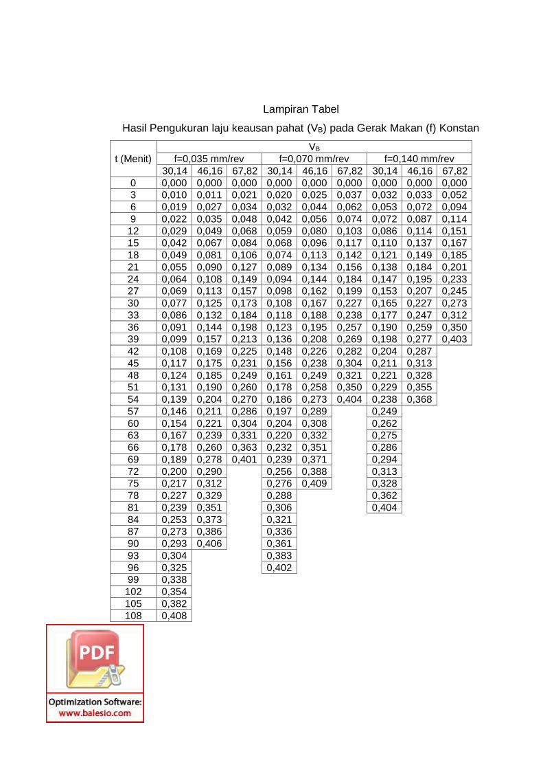
Lampiran Tabel
Hasil Pengukuran laju keausan pahat (VB) pada Gerak Makan (f) Konstan
t (Menit)
VB
f=0,035 mm/rev f=0,070 mm/rev f=0,140 mm/rev
30,14 46,16 67,82 30,14 46,16 67,82 30,14 46,16 67,82
0 0,000 0,000 0,000 0,000 0,000 0,000 0,000 0,000 0,000
3 0,010 0,011 0,021 0,020 0,025 0,037 0,032 0,033 0,052
6 0,019 0,027 0,034 0,032 0,044 0,062 0,053 0,072 0,094
9 0,022 0,035 0,048 0,042 0,056 0,074 0,072 0,087 0,114
12 0,029 0,049 0,068 0,059 0,080 0,103 0,086 0,114 0,151
15 0,042 0,067 0,084 0,068 0,096 0,117 0,110 0,137 0,167
18 0,049 0,081 0,106 0,074 0,113 0,142 0,121 0,149 0,185
21 0,055 0,090 0,127 0,089 0,134 0,156 0,138 0,184 0,201
24 0,064 0,108 0,149 0,094 0,144 0,184 0,147 0,195 0,233
27 0,069 0,113 0,157 0,098 0,162 0,199 0,153 0,207 0,245
30 0,077 0,125 0,173 0,108 0,167 0,227 0,165 0,227 0,273
33 0,086 0,132 0,184 0,118 0,188 0,238 0,177 0,247 0,312
36 0,091 0,144 0,198 0,123 0,195 0,257 0,190 0,259 0,350
39 0,099 0,157 0,213 0,136 0,208 0,269 0,198 0,277 0,403
42 0,108 0,169 0,225 0,148 0,226 0,282 0,204 0,287
45 0,117 0,175 0,231 0,156 0,238 0,304 0,211 0,313
48 0,124 0,185 0,249 0,161 0,249 0,321 0,221 0,328
51 0,131 0,190 0,260 0,178 0,258 0,350 0,229 0,355
54 0,139 0,204 0,270 0,186 0,273 0,404 0,238 0,368
57 0,146 0,211 0,286 0,197 0,289 0,249
60 0,154 0,221 0,304 0,204 0,308 0,262
63 0,167 0,239 0,331 0,220 0,332 0,275
66 0,178 0,260 0,363 0,232 0,351 0,286
69 0,189 0,278 0,401 0,239 0,371 0,294
72 0,200 0,290 0,256 0,388 0,313
75 0,217 0,312 0,276 0,409 0,328
78 0,227 0,329 0,288 0,362
81 0,239 0,351 0,306 0,404
84 0,253 0,373 0,321
87 0,273 0,386 0,336
90 0,293 0,406 0,361
93 0,304 0,383
96 0,325 0,402
99 0,338
102 0,354
105 0,382
108 0,408
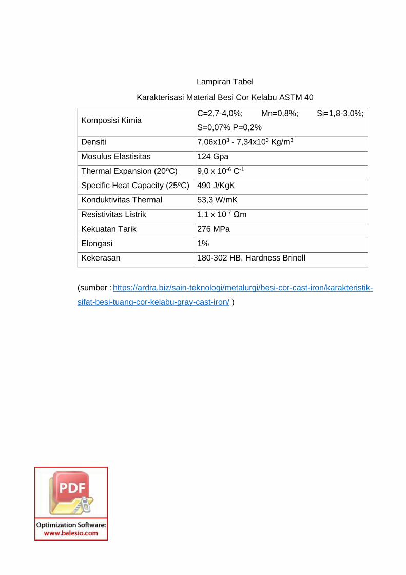
Lampiran Tabel
Karakterisasi Material Besi Cor Kelabu ASTM 40
Komposisi Kimia C=2,7-4,0%; Mn=0,8%; Si=1,8-3,0%;
S=0,07% P=0,2%
Densiti 7,06x10³ - 7,34x10³ Kg/m3
Mosulus Elastisitas 124 Gpa
Thermal Expansion (20oC) 9,0 x 10⁻⁶ C-1
Specific Heat Capacity (25oC) 490 J/KgK
Konduktivitas Thermal 53,3 W/mK
Resistivitas Listrik 1,1 x 10⁻⁷ Ωm
Kekuatan Tarik 276 MPa
Elongasi 1%
Kekerasan 180-302 HB, Hardness Brinell
(sumber : https://ardra.biz/sain-teknologi/metalurgi/besi-cor-cast-iron/karakteristik-
sifat-besi-tuang-cor-kelabu-gray-cast-iron/ )
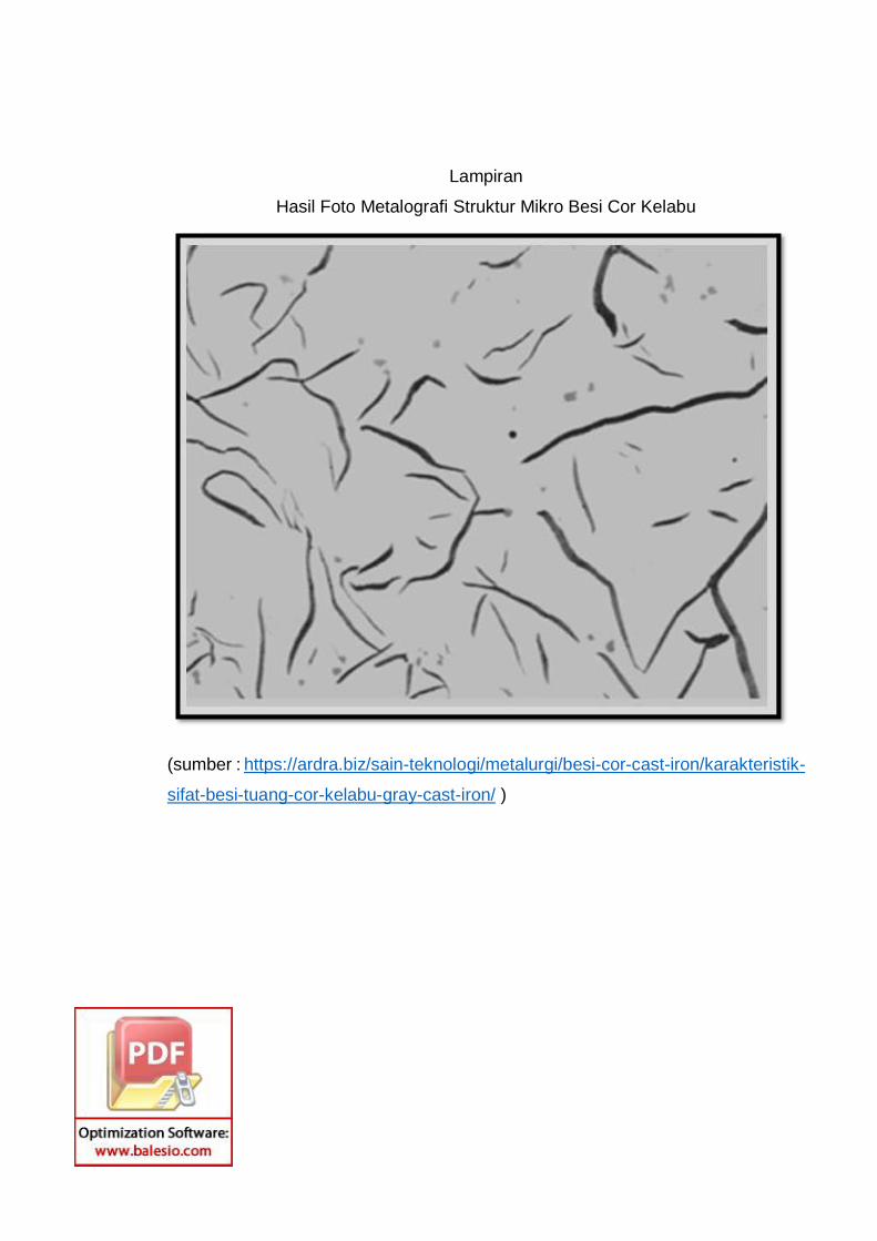
Lampiran
Hasil Foto Metalografi Struktur Mikro Besi Cor Kelabu
(sumber : https://ardra.biz/sain-teknologi/metalurgi/besi-cor-cast-iron/karakteristik-
sifat-besi-tuang-cor-kelabu-gray-cast-iron/ )
L A M P I R A N
J U R N A L
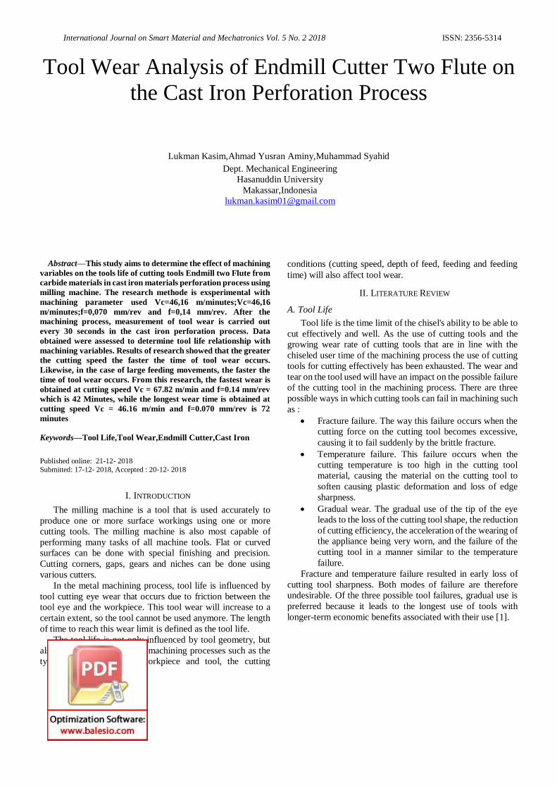
International Journal on Smart Material and Mechatronics Vol. 5 No. 2 2018 ISSN: 2356-5314
Tool Wear Analysis of Endmill Cutter Two Flute on
the Cast Iron Perforation Process
Lukman Kasim,Ahmad Yusran Aminy,Muhammad Syahid
Dept. Mechanical Engineering
Hasanuddin University
Makassar,Indonesia
Abstract—This study aims to determine the effect of machining
variables on the tools life of cutting tools Endmill two Flute from
carbide materials in cast iron materials perforation process using
milling machine. The research methode is exsperimental with
machining parameter used Vc=46,16 m/minutes;Vc=46,16
m/minutes;f=0,070 mm/rev and f=0,14 mm/rev. After the
machining process, measurement of tool wear is carried out
every 30 seconds in the cast iron perforation process. Data
obtained were assessed to determine tool life relationship with
machining variables. Results of research showed that the greater
the cutting speed the faster the time of tool wear occurs.
Likewise, in the case of large feeding movements, the faster the
time of tool wear occurs. From this research, the fastest wear is
obtained at cutting speed Vc = 67.82 m/min and f=0.14 mm/rev
which is 42 Minutes, while the longest wear time is obtained at
cutting speed Vc = 46.16 m/min and f=0.070 mm/rev is 72
minutes
Keywords—Tool Life,Tool Wear,Endmill Cutter,Cast Iron
Published online: 21-12- 2018
Submitted: 17-12- 2018, Accepted : 20-12- 2018
I. INTRODUCTION
The milling machine is a tool that is used accurately to
produce one or more surface workings using one or more
cutting tools. The milling machine is also most capable of
performing many tasks of all machine tools. Flat or curved
surfaces can be done with special finishing and precision.
Cutting corners, gaps, gears and niches can be done using
various cutters.
In the metal machining process, tool life is influenced by
tool cutting eye wear that occurs due to friction between the
tool eye and the workpiece. This tool wear will increase to a
certain extent, so the tool cannot be used anymore. The length
of time to reach this wear limit is defined as the tool life.
The tool life is not only influenced by tool geometry, but
also by all factors related to machining processes such as the
type of material of the workpiece and tool, the cutting
conditions (cutting speed, depth of feed, feeding and feeding
time) will also affect tool wear.
II. LITERATURE REVIEW
A. Tool Life
Tool life is the time limit of the chisel's ability to be able to
cut effectively and well. As the use of cutting tools and the
growing wear rate of cutting tools that are in line with the
chiseled user time of the machining process the use of cutting
tools for cutting effectively has been exhausted. The wear and
tear on the tool used will have an impact on the possible failure
of the cutting tool in the machining process. There are three
possible ways in which cutting tools can fail in machining such
as :
• Fracture failure. The way this failure occurs when the
cutting force on the cutting tool becomes excessive,
causing it to fail suddenly by the brittle fracture.
• Temperature failure. This failure occurs when the
cutting temperature is too high in the cutting tool
material, causing the material on the cutting tool to
soften causing plastic deformation and loss of edge
sharpness.
• Gradual wear. The gradual use of the tip of the eye
leads to the loss of the cutting tool shape, the reduction
of cutting efficiency, the acceleration of the wearing of
the appliance being very worn, and the failure of the
cutting tool in a manner similar to the temperature
failure.
Fracture and temperature failure resulted in early loss of
cutting tool sharpness. Both modes of failure are therefore
undesirable. Of the three possible tool failures, gradual use is
preferred because it leads to the longest use of tools with
longer-term economic benefits associated with their use [1].
International Journal on Smart Material and Mechatronics Vol. 5 No. 2 2018 ISSN: 2356-5314
B. Tool Wear
Gradual wear occurs in two major locations on the cutting
tool, in the area of fist and the main part of the tool. Thus, two
types of wear can be distinguished, namely crater wear which
occurs in the field of growling, while the wear of the edge
(Flank wear) occurs in the main field of the cutting tool. Crater
wear consists of a cavity in the face of the Rake tool that forms
and grows from the movement of the chip that glide to the
surface. High stresses and temperatures characterize the
interplanetary contact of Tool and Chip contributing to wear
and tear. Crater wear consists of a cavity in the face of the Rake
tool that forms and grows from the movement of the chip that
glide to the surface. High stresses and temperatures
characterize the interplanetary contact of Tool and Chip
contributing to wear and tear. Wear of the crater can be
measured either with depth or area. Flank wear occurs on the
Relief face of the cutting tool, this results from friction between
the workpiece surface and the Relief face adjacent to the edge
cutting. Flank wear is measured with a wide wear band, FW.
This wear arm is sometimes called Flank wear land.
As a result of the high level of productivity, which is very
important in high-speed CNC machine used was noticed tool
wear of a Endmill [2]. The criteria recommended by ISO 3685:
1993 to determine the effective tool life for carbides [2], high-
speed steels (HSS) and ceramics are:
TABLE I. RECOMMENDED FOR FLANK WEAR SIZE VBB ON MATERIAL
CUTTING [2].
Tool Material
HSS
Comented
Carbides
Carbides
Coated Operation mm
Roughing VBB 0,35-1.0 0,3-0,5 0,3-0,5
Finishing VBB 0,2-0,3 0,1-0,25 0,1-0,25
C. Cutting Parameters
The cutting speed is determined at the outer diameter of the
milling cutter. It can be converted into spindle rotation speeds
by using the following equation [1]:
𝑉𝐶 =𝜋𝑑𝑛
1000 (1)
Where :
- Vc = Cutting Speed (m/minute)
- d = diameter of cutter (mm)
- n = spindle speed (rpm)
III. RESEARCH METHOD
A. Implementation
This research was conducted in May-June 2018 in the
Mechanical Technology Laboratory of the Department of
Engineering, Faculty of Engineering, Hasanuddin University.
B. Tools
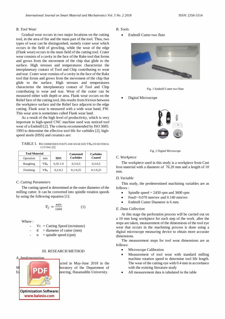
• Endmill Cutter two flute
Fig. 1 Endmill Cutter two flute
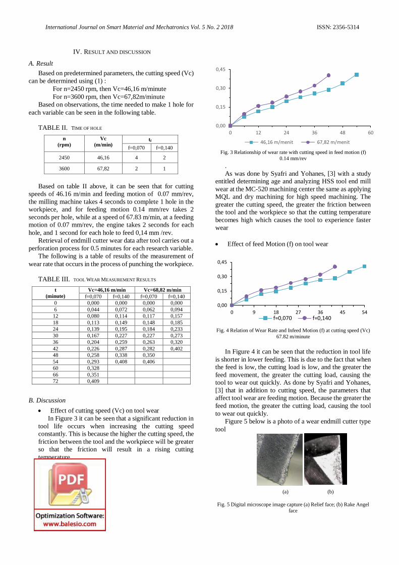
• Digital Microscope
Fig. 2 Digital Microscope
C. Workpiece
The workpiece used in this study is a workpiece from Cast
Iron material with a diameter of 76.20 mm and a length of 10
mm.
D. Variable
This study, the predetermined machining variables are as
follows :
• Spindle speed = 2450 rpm and 3600 rpm
• Feed= 0.070 mm/rev and 0.140 mm/rev
• Endmill Cutter Diameter is 6 mm.
E. Data Collection
At this stage the perforation process will be carried out on
a 10 mm long workpiece for each step of the work. after the
steps are taken, measurement of the dimensions of the tool eye
wear that occurs in the machining process is done using a
digital microscope measuring device to obtain more accurate
dimensions.
The measurement steps for tool wear dimensions are as
follows:
• Microscope Calibration
• Measurement of tool wear with standard milling
machine rotation speed to determine tool life length.
The wear of the cutting eye with 0.4 mm in accordance
with the existing literature study
• All measurement data is tabulated in the table
International Journal on Smart Material and Mechatronics Vol. 5 No. 2 2018 ISSN: 2356-5314
0,00
0,15
0,30
0,45
0 12 24 36 48 60
46,16 m/menit 67,82 m/menit
0,00
0,15
0,30
0,45
0 9 18 27 36 45 54f=0,070 f=0,140
IV. RESULT AND DISCUSSION
A. Result
Based on predetermined parameters, the cutting speed (Vc)
can be determined using (1) :
For n=2450 rpm, then Vc=46,16 m/minute
For n=3600 rpm, then Vc=67,82m/minute
Based on observations, the time needed to make 1 hole for
each variable can be seen in the following table.
TABLE II. TIME OF HOLE
n
(rpm)
Vc
(m/min) tf
f=0,070 f=0,140
2450 46,16 4 2
3600 67,82 2 1
Based on table II above, it can be seen that for cutting
speeds of 46.16 m/min and feeding motion of 0.07 mm/rev,
the milling machine takes 4 seconds to complete 1 hole in the
workpiece, and for feeding motion 0.14 mm/rev takes 2
seconds per hole, while at a speed of 67.83 m/min, at a feeding
motion of 0.07 mm/rev, the engine takes 2 seconds for each
hole, and 1 second for each hole to feed 0,14 mm /rev.
Retrieval of endmill cutter wear data after tool carries out a
perforation process for 0.5 minutes for each research variable.
The following is a table of results of the measurement of
wear rate that occurs in the process of punching the workpiece.
TABLE III. TOOL WEAR MEASUREMENT RESULTS
t
(minute)
Vc=46,16 m/min Vc=68,82 m/min
f=0,070 f=0,140 f=0,070 f=0,140
0 0,000 0,000 0,000 0,000
6 0,044 0,072 0,062 0,094
12 0,080 0,114 0,117 0,157
18 0,113 0,149 0,148 0,185
24 0,139 0,195 0,184 0,233
30 0,167 0,227 0,227 0,273
36 0,204 0,259 0,263 0,320
42 0,226 0,287 0,282 0,402
48 0,258 0,338 0,350
54 0,293 0,408 0,406
60 0,328
66 0,351
72 0,409
B. Discussion
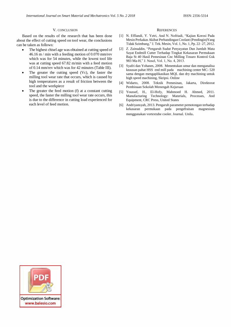
• Effect of cutting speed (Vc) on tool wear
In Figure 3 it can be seen that a significant reduction in
tool life occurs when increasing the cutting speed
constantly. This is because the higher the cutting speed, the
friction between the tool and the workpiece will be greater
so that the friction will result in a rising cutting
temperature.
Fig. 3 Relationship of wear rate with cutting speed in feed motion (f)
0.14 mm/rev
.
As was done by Syafri and Yohanes, [3] with a study
entitled determining age and analyzing HSS tool end mill
wear at the MC-520 machining center the same as applying
MQL and dry machining for high speed machining. The
greater the cutting speed, the greater the friction between
the tool and the workpiece so that the cutting temperature
becomes high which causes the tool to experience faster
wear
• Effect of feed Motion (f) on tool wear
Fig. 4 Relation of Wear Rate and Infeed Motion (f) at cutting speed (Vc)
67.82 m/minute
In Figure 4 it can be seen that the reduction in tool life
is shorter in lower feeding. This is due to the fact that when
the feed is low, the cutting load is low, and the greater the
feed movement, the greater the cutting load, causing the
tool to wear out quickly. As done by Syafri and Yohanes,
[3] that in addition to cutting speed, the parameters that
affect tool wear are feeding motion. Because the greater the
feed motion, the greater the cutting load, causing the tool
to wear out quickly.
Figure 5 below is a photo of a wear endmill cutter type
tool
(a) (b)
Fig. 5 Digital microscope image capture (a) Relief face; (b) Rake Angel
face
International Journal on Smart Material and Mechatronics Vol. 5 No. 2 2018 ISSN: 2356-5314
V. CONCLUSION
Based on the results of the research that has been done
about the effect of cutting speed on tool wear, the conclusions
can be taken as follows:
• The highest chisel age was obtained at cutting speed of
46.16 m / min with a feeding motion of 0.070 mm/rev
which was for 54 minutes, while the lowest tool life
was at cutting speed 67.82 m/min with a feed motion
of 0.14 mm/rev which was for 42 minutes (Table III).
• The greater the cutting speed (Vc), the faster the
milling tool wear rate that occurs, which is caused by
high temperatures as a result of friction between the
tool and the workpiece
• The greater the feed motion (f) at a constant cutting
speed, the faster the milling tool wear rate occurs, this
is due to the difference in cutting load experienced for
each level of feed motion.
REFERENCES
[1] N. Effiandi, Y. Yetri, And N. Nofriadi, “Kajian Korosi Pada
Mesin Perkakas Akibat Perbandingan Coolant (Pendingin)Yang
Tidak Seimbang,” J. Tek. Mesin, Vol. 1, No. 1, Pp. 22–27, 2012.
[2] Z. Zainuddin, “Pengaruh Sudut Penyayatan Dan Jumlah Mata
Sayat Endmill Cutter Terhadap Tingkat Kekasaran Permukaan Baja St 40 Hasil Pemesinan Cnc Milling Tosuro Kontrol Gsk
983 Ma-H,” J. Nosel, Vol. 1, No. 4, 2013.
[3] Syafri dan Yohanes, 2008. Menentukan umur dan menganalisa
keausan pahat HSS end mill pada machining center MC- 520
sama dengan mengaplikasikan MQL dan dry machining untuk
high speed machining, Skripsi. Online
[4] Widarto, 2008. Teknik Pemesinan, Jakarta, Direktorat
Pembinaan Sekolah Menengah Kejuruan
[5] Youssef, H., El-Hofy, Mahmoed H. Ahmed, 2011.
Manufacturing Technology: Materials, Processes, And
Equipment, CRC Press, United States
[6] Andriyansyah, 2013. Pengaruh parameter pemotongan terhadap kekasaran permukaan pada pengefraisan magnesium
menggunakan vortextube cooler. Journal. Unila.