Embed Size (px)
Citation preview
L yl
TECHNICAL REPORT BRL-TR-3080
AD-A219 374BRL -'0
E3FII
LARGE-SCALE SIMULATIONS OF MONOLITHICAND SEGMENTED PROJECTILES
IMPACTING SPACED ARMOR
DANIEL R. SCHEFFLERTHOMAS M. SHERRUCK DTICS~DTIC
ELECTEFEBRUARY 1990 MAR 16 1990 D
AM3OVW M~ M"R RMZIAS% DISTMMTIN UNLU~N=.
U.S. ARMY LABORATORY COMMAND
BALLISTIC RESEARCH LABORATORYABERDEEN PROVING GROUND, MARYLAND
"A A " ' - "' "'•,,•
DESTRUCTION NOTICE
Destroy this Import when it is no longer needed. DO NOT remt it to the originator.
Additional copies of this raort may be obtained from do National Technical Information Service,U.S. DepatMent of Commerce, 5285 Port Royal Road, Spdngfeld, VA 22161.
The findin of this report am not to be consmtued an official Depqrnmnt of the Army position,unless so designd by odter authorized documents.
The use of trade names or m=a acntuers' names in this report does not convtiute indorrement ofany commercial product.
REPORT DOCUMENTATION PAGE OM.ft ,,,1P~tfM '.'u J MiW fir UK.. md a g4^40ftmfa. 16 "1W U#w~ag I haww ft.vgsq Onudfl Utwi UWfr*engMMmW. uVwV00% eIM g due WANK
... . ..- * II 1 hJ . 111 1 L to"m
DMININ-l~f-ft 104 ý Ie4 mC : =
1. AGENCY USE -. ? (/a 0 M.---Ow. 1, IOki DATo . lEIpRT TYPE AND DAVIS
4. TB Final. June 88 to SntUETITLarge-Scale Simulations of Monolithic and Segmented Projectiles Impacting Spaced
Armor
SLAUTHCRS) " ""
Scheffler, Daniel R., and Sherrick, Thomas M.
i
20=4dlN1 OlAGANIZATION NAMI(S) AND A O VEISRU) L_ PEIIPOIMING OIGANIZATIONREPORT NUMliR
3. SPONSORIN" MONITOIUN" A4ENCY NAME(S) AND AOBRSIRII) 11. SPONIOIING/Mo~rrOIJN.
US Amy Ballistic Laboratory AN1 RIPO MUIR
AMTT: SLCBR-DD-TAberdeen Proving Ground, MD 2100-5M66 BRL-TR-3080
1t. SUREIMENTARY NOTES
.124. $•ISMM17AVAWNAIJTY STATIMINT 12b DISTRIBUTION CODE
Approved f.o public release; distribution Is unlimited.
11. ABSTRACT (M• Mu ' 200 =..W.
Numerical simulations are presented describing the performance of segmented and monolithic kinetic energy penetralorsagainst oblique-spaced-rolled homogewous armor (RHA) plates. The three-dimensional simulations depict the effectsof striking velocity; target plate thickness-to-feneMor dicameter ratio (T/D); segment spuing-to-penetrator diameterrailo (S/D); and the number of segments, o.. penetrator performance.
14. SU(AC TIM" It NUMBER OF PAGES
kinetic energy penetrator, rolled homogeneous armor, RHA, segmented penetrator, 66spaced armor, inipac computer simulations, penetraion, perforation, kineu it. PIKE cooleanrrv. armor ,(/.,::( ..
TT s9culm €•SWICATON ISL SECURITY CLASSOIATICII 1S. s•1CU1 T aSWCAT, N . U.r-TA•I • sP AB' ' COF REPORT OF THIS PAGE OF ABSTRACT
TI NC'T A•"11iD UNCLASSIFIED ULINI 754 90 55Standard Form 29 6 (Rev. 2 -69)
pvHrinw by ANSI led. M-4dJIumc~ N Sttlt
SFO fAPLffINpsxm
Th Report Documentation Page, (ROP) is used in announcing and catalioging reports It is lmo~rsantbOwa this inform ,ation be conjistent with the rest of the report. particularty the cover and title pape.Iunstructions fdr filling in sad~block. of the form follow.. it is emportang:t doywt~ the :j MZet ~~
gepesalowm Il requhmneents.___ ___________
fto 1. MomIC Use Only (Leave lAnO) IlOck 128. mistrikmeruAailability Jiasam
ock . aa m. PN nullcaion ateDenotes public avallabllty or limitations. Cite anyd"y, meonthOt, andl pulctindt availability to the public. Enter additionalIncluding day motady ,If available eg. limitations or special markings In all capitals (e.g.Jan 36). Must cite at least the year. NOPORN. REL.. ITAR).
Ioc 3. Tyne of fteaort and Oates Covered. D S.Q QStehotherreo.. itd..laec f~,
applcabenter Oje OYO*reoý,W dates (0-g. 10 O~'~Jun a -30 Jun6so. DW oi.See authorites.
Oick4. " .A~ttioJA tken romNASA - See Handbook NMIS 220032.teWof ttheo .!0s reprtht p.oW ft O'"S i most
meaningful and complete information. When areport is prepared in more than one volume,BlcIMDitbuonQ .repeat the primary titlet, add volume number, and lr12 Dfd iu.a
include subtitle for.thespecifk volume. OnDO -Lo"bakclassfied documents enter the title classification DO -Ete OI blan buio.teorein1 * ntr Editrbuio cteoreIn paenthses.from the Standard Distribution for
Nock L. Fundiau Numb* To .Include contract Unclaslsified Scientific and Technicaland grant numbers; may include program ~PRimelement numbers), project number(s), tas NASA - Leaveblank.number(s), and work unit numberls). Use the NIIS - Leave blank.following labels:6 - conrant PR B jsc lock 13. AblCi Ind ude.a brlf(Mexlnwns,
Orn A T2W worth factual sumayfVeosPI - Program WU, -Work Unit significant information contained in the report.
Element Accession No.
Blocks 6. AuhW Name(s) of person(s) Block 14. 1&lWjZIg~ml. K~eywords or phrasesresponsible for writing the report, perform..ing Identifying major subjects In the report.the research, or credited with the content of thereport. if editor orcomipiler. this s hould followthe name(s). Nock 15. Numb.ger o b . Enter the total
number of pages.Nock 7. Parformina Oroanization NamneWs and
~d~a~ak.Sel-exlaatoy.Block 1f. Me CoenIter appropriate priceNock L. etd ingm Oroanf1maO~tia eo code (NAiS only).NuiMh. Enter the unique alphanumeric reportnumber(s) assigned by the organization Mocks 17. -It. Security Classifications. Self.performing the report. explanatory. Enter U.S. Security Classification inNock 9. SoonsorinalMggitorln. Agency Na1me(s) accordance with U.S. Security Regulations (I.*.,and.6fttow.un Self-explanatory. UNCLASSIFIED). If form contains classified
information, stamp classification on the top andBlock 10. Sg~mUgitrm~~c bottom of the page.122MS Nmbsr. (if known)
lock 11. SuamnayNts Enter Nock 20. Limitation of Abstrae This block mustinforuhation not Included elsewhere such as: be completed to assign a limitation to thePrepared In cooperation with ... ; Trans. of..., To be abstract. Enter either UL (unlimited) or SAR (samepublished in.... When a report Is revised, inciude as report). An entry in this block Is necessary if
astatement whether the new roport supersedes the abstract is to be limited. if blank, the abstractor supplements the older report. is assumed to be unlimited.
Standard Pans MW Bak (Nov. 249)
TABLE OF CONTENTS
Page
TABLE OF CONTENTS .................... iii
LIST OF FIGURES .................. ..................... v
Paragraph 1 INTRODUCTION ............. ....................... 1
2 SIMULATION MATRIX ............................ .. I
3 RESULTS AND DISCUSSION .. . .............. 3
4 CONCLUSIONS ................ ....................... .. 23
LIST OF REFERENCES ........... .................... ... 24
APPENDIX A - Keel Input Data ....... ............... ... 25
APPENDIX B - Material Properties ....... ............. 35
APPENDIX C - Plots Used For Residual Mass Calculations . . 37
DISTRIBUTION LIST .............. ...................... 55
Acoession Forz'
?4TIS GRA&IDTIC TAB [Unannounced [Zuetificatio------
Distribution/ _
Availability Codes
Spooial
{ii

Imrn~hoNALLY Lzpr BLANK.
IVV
LIST OF FIGURES
Figure Page
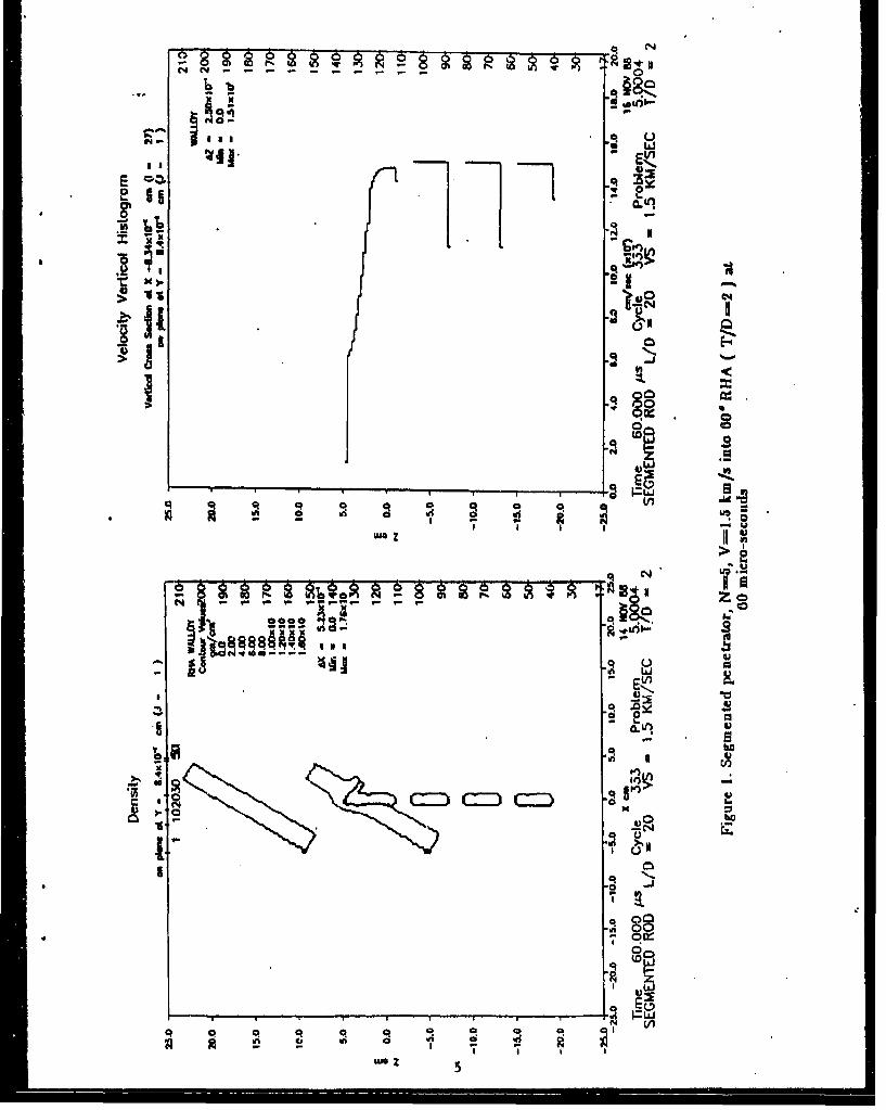
i. Segmented penetrator, N-5, V-1.5 km/s into 60' RHA (T/D-2) at 60microseconds . .......................................... 5
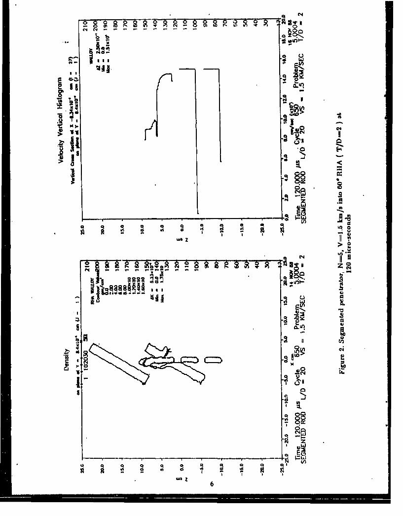
2. Segmented penetrator, N-5, V-1.5 km/s into 60' RHA (T/D-2) at 120microseconds.................. . . . . . . ..... ........... 6
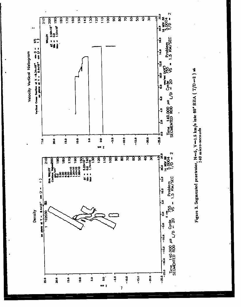
3. Segmented penetrator, N-5, V-1.5 km/s into 60' MA (T/D-2) at 140microseconds . . . . . . . . . . . . . . . . ............ 7
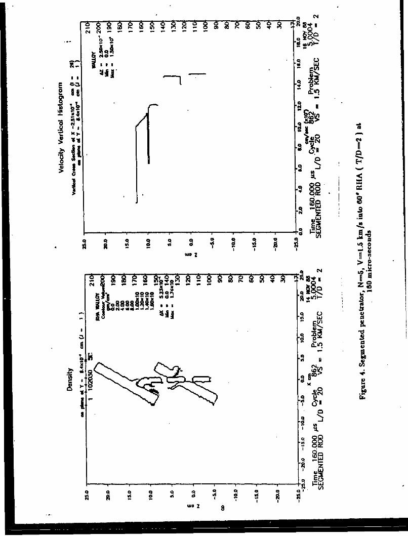
4. Segmented penetrator, N-5, V-1.5 km/s into 60' RHA (T/D-2) at 160microseconds ...................... ................ ....... . . 8
5. Segmented penetrator, N-S, V-1.5 km/s into 600 RHA (T1'D-2) at 180iaicroseconds . . ........................... 9
6. Seqmented penetrator, N-5, V-2.0 km/s into 60' RHA (T/D-2) at 60microseconds ......... ......... ........ . . 10
7. Segmented penetrator, N-5, V-2.0 km/s into 60' RHA (T/D-2) at 80mioroseconds . . . . . . . . . . . . . . .......... . . .. 11
8. Segmented penetrator, N-5, V-2.0 km/s into 600 RHA (T/D-2) at 100microseconds ...................... ................ ...... . .12
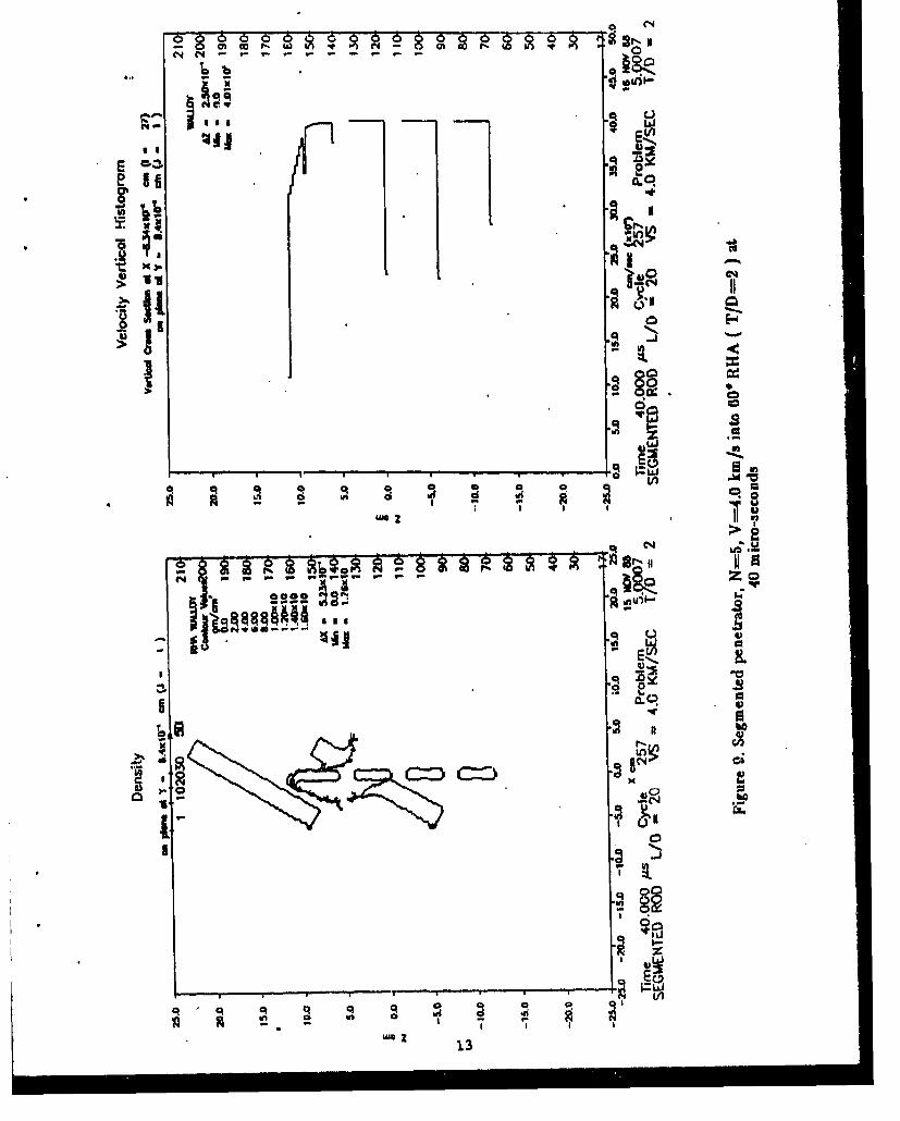
9. Segmented penetrator, N-5, V-4.0 km/s into 60' RHA (T/D-2) at 40microseconds ...................... ....................... ... 13
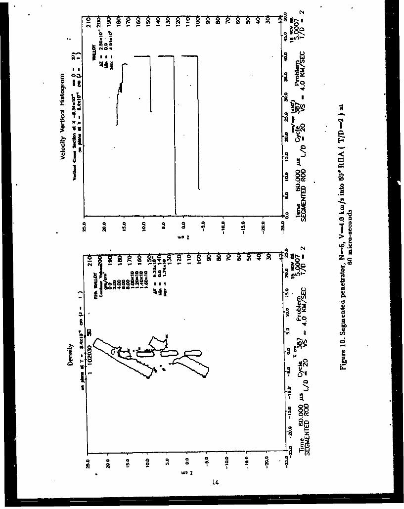
10. Segmented penetrator, N-5, V-4.0 km/s into 60' RHA (T/D-2) at 60microseconds . . . . . . . . . . ......... . . . . . . . . . 14
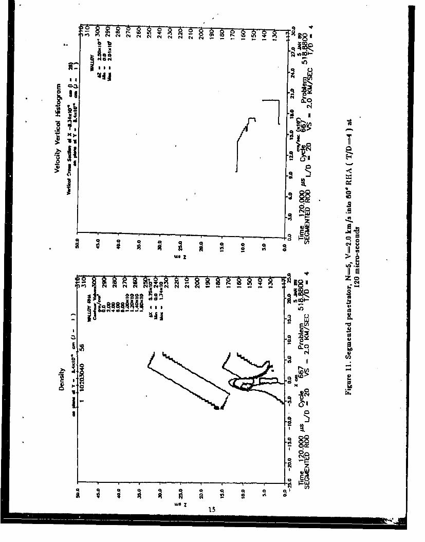
11. Segmented penetrator, N-5, V-2.0 km/s into 60' RHA (T/D-4) at 120microseconds . . . . . . . . . . . ......... . ........ 15
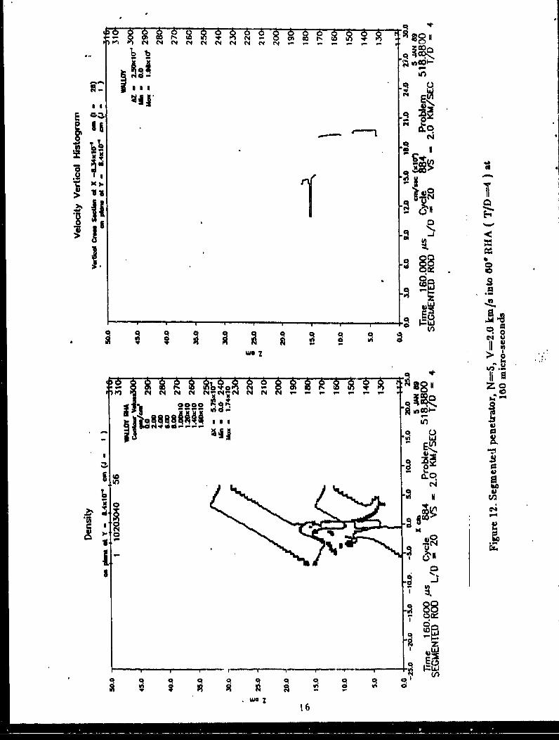
12. Segmented penetrator, N-5, V-2.0 km/s into 60* RHA (T/D-4) at 160microseconds ...................... ..................... ... .. 16
13. Segmented penetrator, N-5, V-3.0 km/s into 60' RPA (T/D-4) at 4)microseconds ................ ............................ 17
14. Segmented penetrator, N-5, V-3.0 km/s into 600 RHA (T/D-4) at 80microseconds .......................... ........................ 18
15. Segmented penetrator, NH-5 V-3.0 km/s into 60' RHA (T/D-4) at 240microseconds .............................................. 19
16. Segmented penetrator, N-5, V-4.0 km/s into 60' RHA (T/D-4) at 120microseconds .................... .......................... .. 20
17. Segmented penetrator, N-20, V-4.0 km/s into 600 RHA (T/D-4) at 170microseconds .................... .......................... .. 21
18. Monolithic penetrator, N-1, V-4.0 km/s into 60' RHA (T/D-4) at 160microseconds .................... .......................... .. 22
'p

II~mmoNALLY LE~ BLAN4K,
ACKNOWLEDGEMENTS
The authors wish to thank the reviewers, Dr. Ennis F. Quigley andMr. Kent D. Kimsey, for their helpful conents and suggestions in preparing thisreport. Special thanks go to Mrs. Brenda L. Tucker and Miss Melissa A. Boonewho prepared the manuscript.
vii

IMMMONALLY LE"T BLANK.
viii
I. INTRODUCTION
Within the last several years there has been a lot of interest in theperformance of segmented kinetic energy penetrators at velocities greater than2 km/s. Both experimental and analytical investigations of the penetrationmechanisms have been conducted. For example, in 1981 V. Kucher', conducted 2-Dsimulations of a segmented projectile that showed improved performance forsegmented projectiles and improved performance with increased segment spacing.Since then, several computer studies have been conducted, among them W. de Rossetand K. D. Kimsey', D. R. Scheffler', and R. T. Sedgwick and co-workers 4, allshowed improved penetrator performance for the segmented rod over an equivalentmass and diameter monolithic rnd. In addition to computer simulations,experiments conducted by A. Charter*'$', and Bell' also suggest that segmentedpenetrators exhibit improved performance.
Numerical simulations are well suited for the study of segmented kineticenergy penetrators. Numerical studies permit the examination of segmentedpenetrators without the typical problems encountered in ballistic tests such as;alignment of the individual segments, constraints of pre-extended projectilelengths, projectile yaw, structural integrity of the launch package, andsynergistic effects of carrier tubes or carrier rods on overall penetration.Thus, simulations can increase our understarning of the penetration phenomenonas well as supplement the limited ballistic test data.
Most of the data in the literature concentrates on the performance of high-velocity segmented kinetic energy penetrators against semi-infinite steel armor.Some ballistic tests of segmented projectiles impacting spaced plate arrayshave been conducted; however, the data is sparse. For example, A. Charters""'''..conducted a limited number of ballistic tests ahowing that each segment "punchesthrough" a target plate in an array allowing the remaining segments to passthrough undisturbed, each defeating one plate. Since computations are wellsuited for modeling segmented projectile impacts, a series of three-dimensionalsimulations have been conducted to characterize the penetration/perforationphenomenon against spaced armor. The projectile impacts were modeled usingversion 121 of the HULL finite-difference code.
HULL","' is an Fulerian wave propagation code that uses a second orderaccurate finite-difference scheme. The material advection scheme is first order.The code solves the partial differential equations of continuum mechanicsignoring heat conduction and viscosity terms. The Mie-Gruneisen equation ofstate is used to model solids. After vaporization occurs, the Gamma Law equationis used to model the gas. Explosives can be modeled using the Jones-Wilkins-Leeequation of state. Material failure models include: maximum principle stress,maximum principle strain, and the Hancock-Mackenzie triaxial failure model"2 .When material failure occurs, a numerically significant void (i.e. air), isintroduced in the cell which permits relaxation of the tensile forces.Recompression is permitted.
2. SIMULATION MATRIX
A series of three-dimensional simulations have been conducted to determinethe performance of segmented projectiles striking spaced armor. The performanceof the segmented projectile is measured relative to an equivalent massmonolithic penetrator. The length-to-diameter ratio, L/D, of the monolithictungsten alloy (90W-7Ni-3Fe) penetrator is 20, with a total mass of 274 grams.The segmented projectile geometry separates the monolithic rod into N individualsegments with the same diameter as the monolithic projectile.
A number of impact conditiono have been modeled to characterize the effectsof: striking velocity (1.5-4.0 km/a); target thickness-to-penetrator diameterratio, T/D, (2 and 4); segment spacing-to-penetrator diameter ratio, S/D, (0 to8); and the number of individual segmenti, N, (5 and 20) on penetration/perforation performance. The computational matrix is summarized in the Table1. For the cases modeled, the target was comprised of two rolled homogeneousarmor (RHA) plates with the same T/D ratio and a normal spacing of 50.8 mm atan obliquity of 60 degrees.
Table 1. Computational Matrix (Nominal Projectile Mass 274 grams).
Problem No. Velocity N* S/D* T/DS.... {(10 /s) ,, ..
5.0004 1.5 5 1 25.0000 1.5 1 0 25.0005 2.0 5 1 25.0001 2.0 1 0 25.0006 3.0 5 1 25.0002 3.0 1 0 25.0007 4.0 5 1 25.0003 4.0 1 0 2
518.8800 2.0 5 1 46.0002 2.0 1 0 4
518.8833 3.0 5 1 46.0003 3.0 1 0 4
518.8844 4.0 5 1 46.0004 4.0 1 0 47.0001 4.0 5 4 47.0002 4.0 58 48.0000 4.0 20 1 4
*NOTR N - I Lmlieu a mAlItbLe pltIo394Il
IOM loi eeftanI projetlea #lainI.t
In an effort to preserve material interfaces and minimize material diffusiontypically encountered in Eulerian codes, a constant subgrid was chosen for thex-y plane covering a region two diameters away from the penetrator. The constantsubgrid provides six cells across the diameter of the penetrator. Beyond theconstant subgrid in the x-y plane, an expansion factor of 1.1 was used to keepproblem size and runtime within practical limits. In the z-direction, or axialdirection. a constant cell spacing was used, which was 1.5 times the spacing ofthe constant subgrid in the x-y plane. The number of cells used to model aparticular problem depended on the size of the target plates and overall lengthof the penetrator; however, the cell sizes in the constant sub-grid remainedthe same for all simulations. Appendix A contains a listing of KEEL input datafor all of the problems modeled. If the only difference in a particular problemwas the striking velocity, inpuxt data is listed for only one velocity.
The hydrodynamic behavior of the metals were modeled using the Mie-Gruneisenequation of state. The coefficients for the equation of state data were obtainedfrom Kohn".
An incremental elastic-plastic fozmulation following the description givenby Wilkins" is used to describe the deviatoric response of the metals. Anelasetic-perfectly plastic model has been used for the tungsten alloy and RHA with
2
20 kb" and 15 kb" yield strengths, respectively. A complete listing of the
material properties and equation of state data are provided in Appendix B.
3. RESULTS AND DISCUSSION
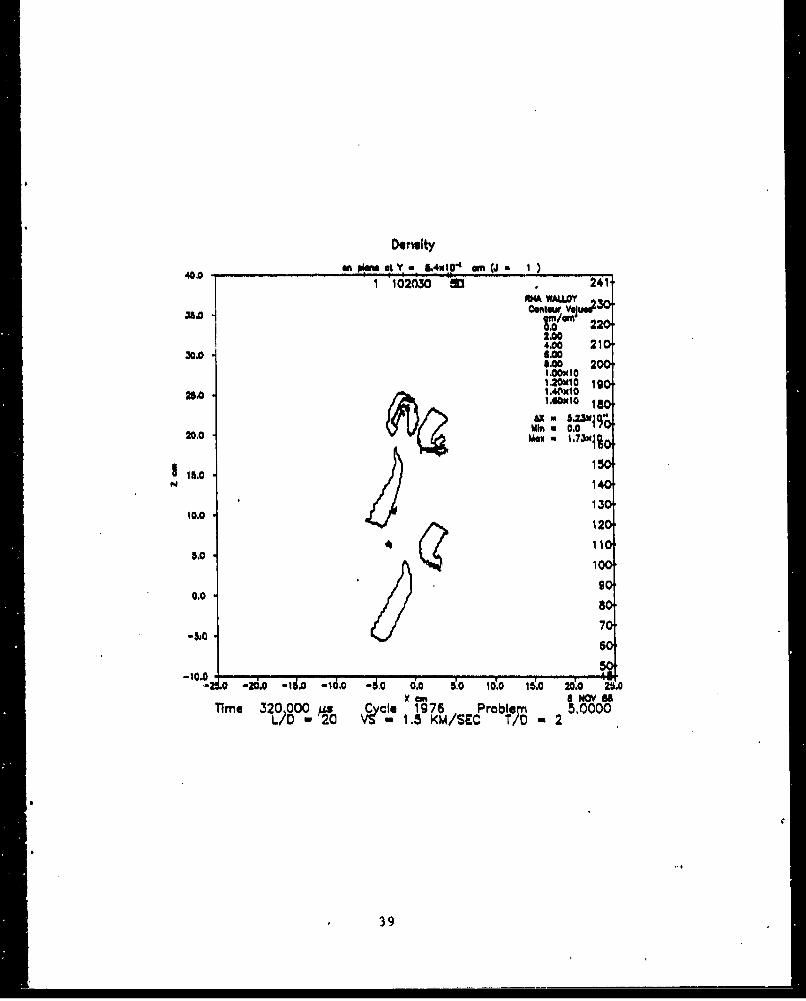
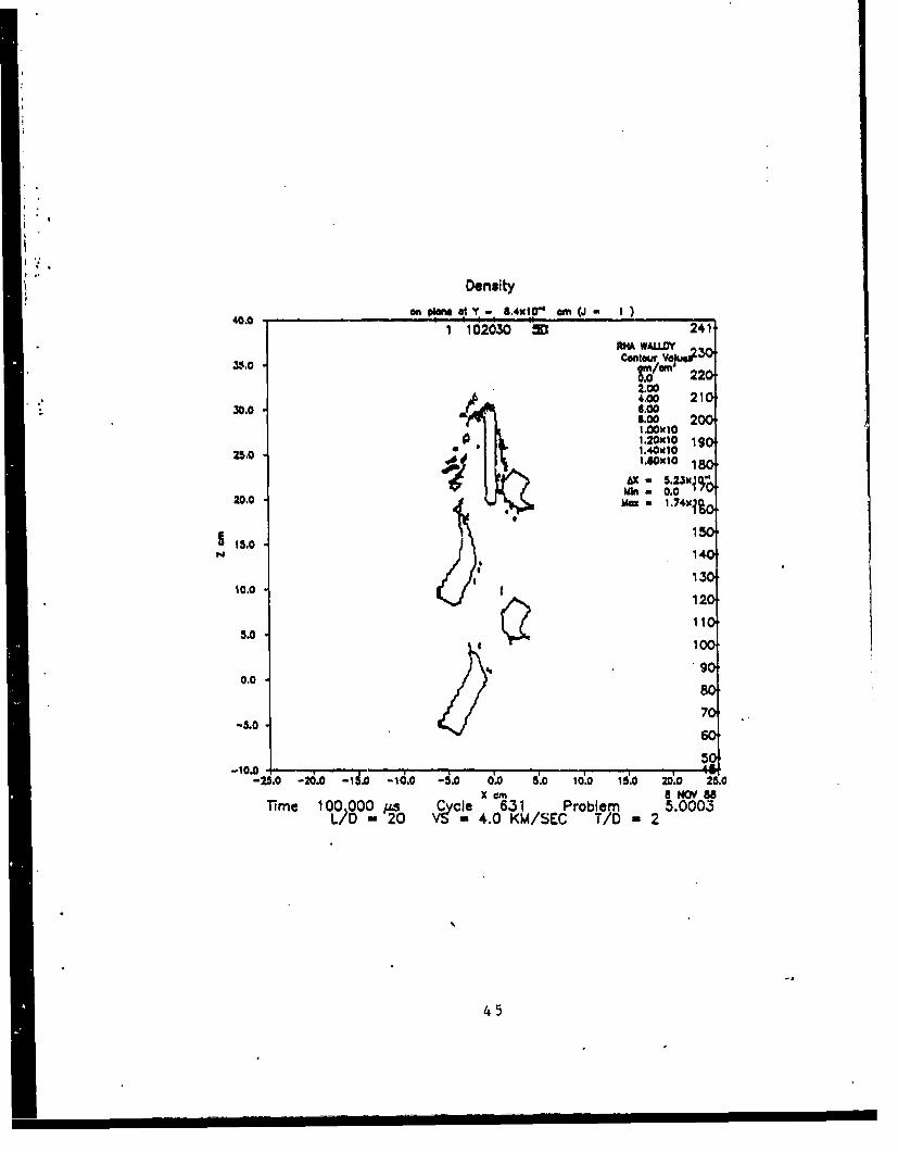
Residual penetrator mass and residual kinetic energy have been used tomeasure performance. The greater the residual penetrator mass at a givenvelocity, the greater its performance. Residual mass was determined using thesame technique ballisticians use to determine residual mass from radiographs.The complete set of density contour plots from which residual mass was determinedcan be found in Appendix C. Residual kinetic energy was determined using theresidual mas= from density contour plots and the velocity from velocityhistograms. For the segmented penetrators residual energy is the summation ofthe individual segment residuals.
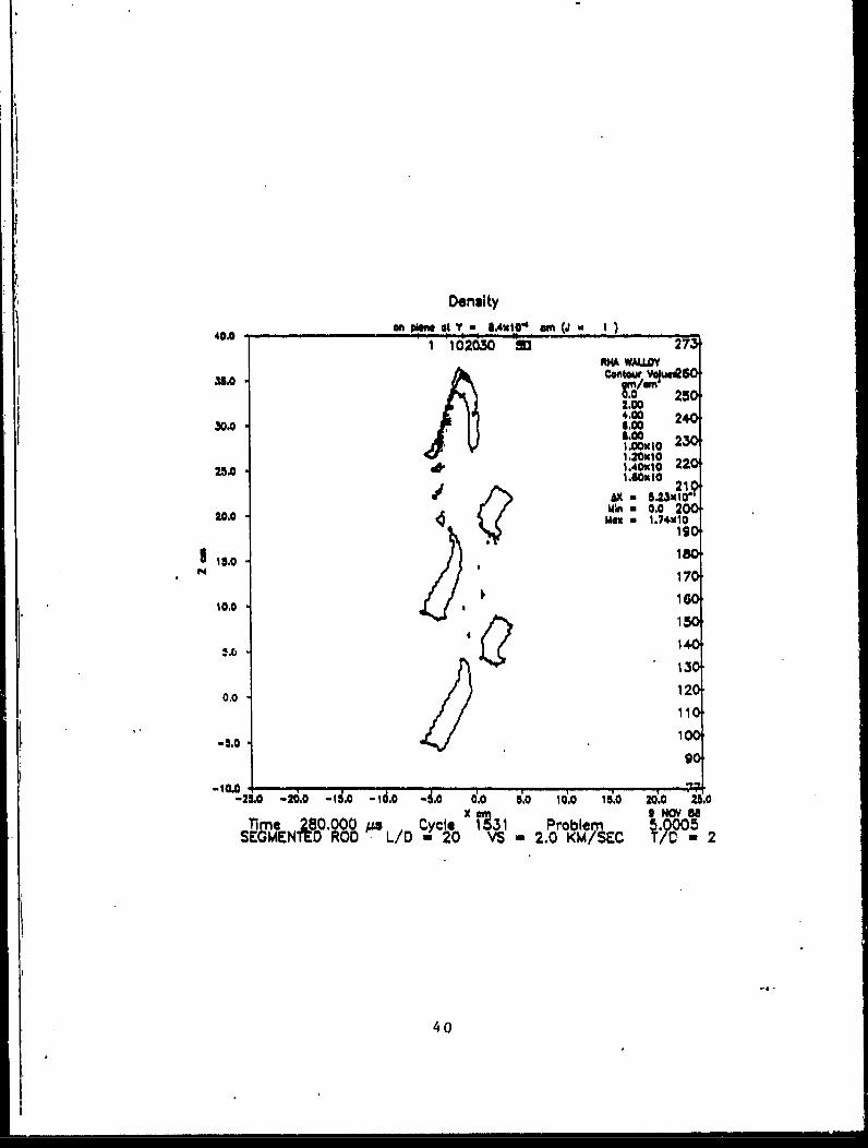
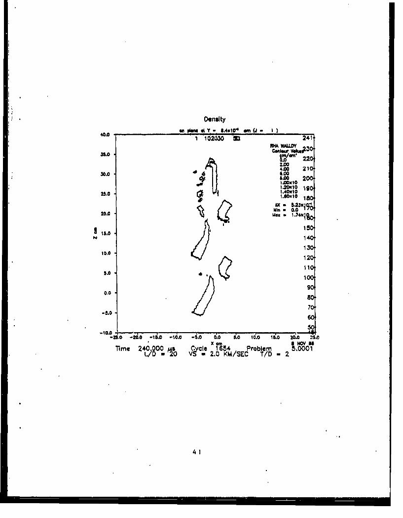
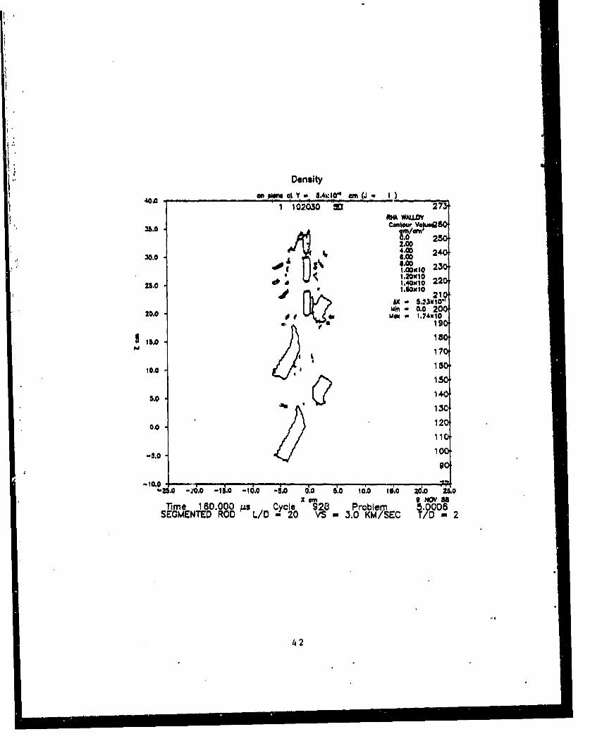
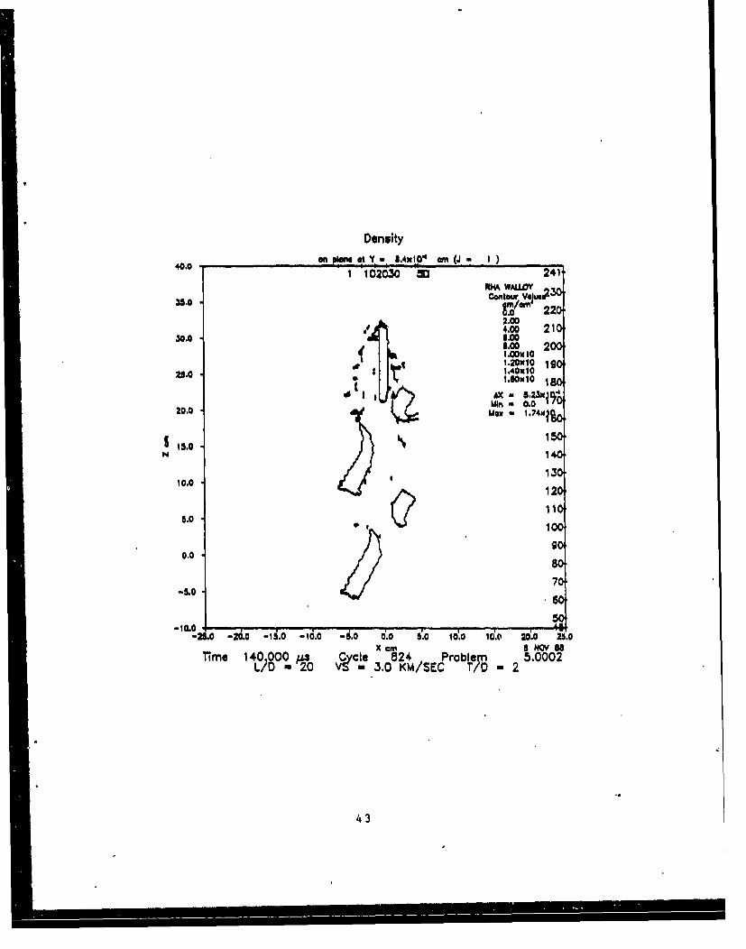
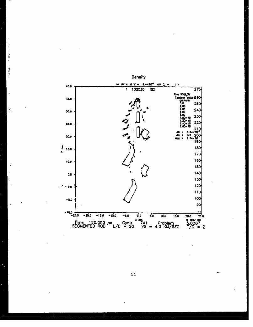
Results for the simulations against the RMA spaced plates for T/D of 2 aresummarized in Table 2. Table 2 shows a significantly greater (31 percent)residual mass for the monolithic penetrator at a velocity of 1.5 km/s. Theresidual kinetic energy of both monolithic and segmented penetrators are aboutthe same. At higher striking velocities the segmented penetrator showsessentially the same if not greater performance than the monolithic penetrator.Figures 1 to 5 show velocity histograms and density contour plots 'or thesegmented penetrator at a velocity of 1.5 km/s at various times. The figuresshow a sequence of events in which individual segments collide and eventuallybecome misaligned, i.e. not colinear. At 2 km/s collisions between individualsegments still occur. Figures 6 to 8 show the lead segment losing velocity afterperforating the first target allowing the next segment the catch up. However,misalignment of individual segments is not observed. The collisions tend tomake the segmented rod appear much like a monolithic rod since the lead segmentis not entirely eroded before being impacted by a subsequent segment. At 4 km/s,see Figures 9 and 10, most of the lead segment is eroded in perforating thefirst target plate. Though the lead segment is impacted by the second segment,only minimal loss of kinetic energy takes place in the second segment. Trailingsegments uninvolved in collision retain their initial velocities and suffer noloss in kinetic unergy. Due to the decrease in the time interval between targetplates, no further collisions occur until lead segments impact the next plate.
TABLE 2. Residual Mass of Monolithic and Segmented Rods (N-5, S/D-l)against T/D-2 Spaced Plates
Striking Striking Segmented Segmented Monolithic MonolithicVelocity Energy Residual Residual Residual Residual(km/3) (MJ) Mas ( ars) Energy (MIJ) Mass (0s) -Eneriv (MJ)
1.5 0.308 47.9 0.016 63.0 0.0182.0 0.548 107.0 0.166 108.0 0.1473.0 1.233 149.0 0.637 143.0 0.5894.0 2.192 152.0 1.183 150.0 1.141
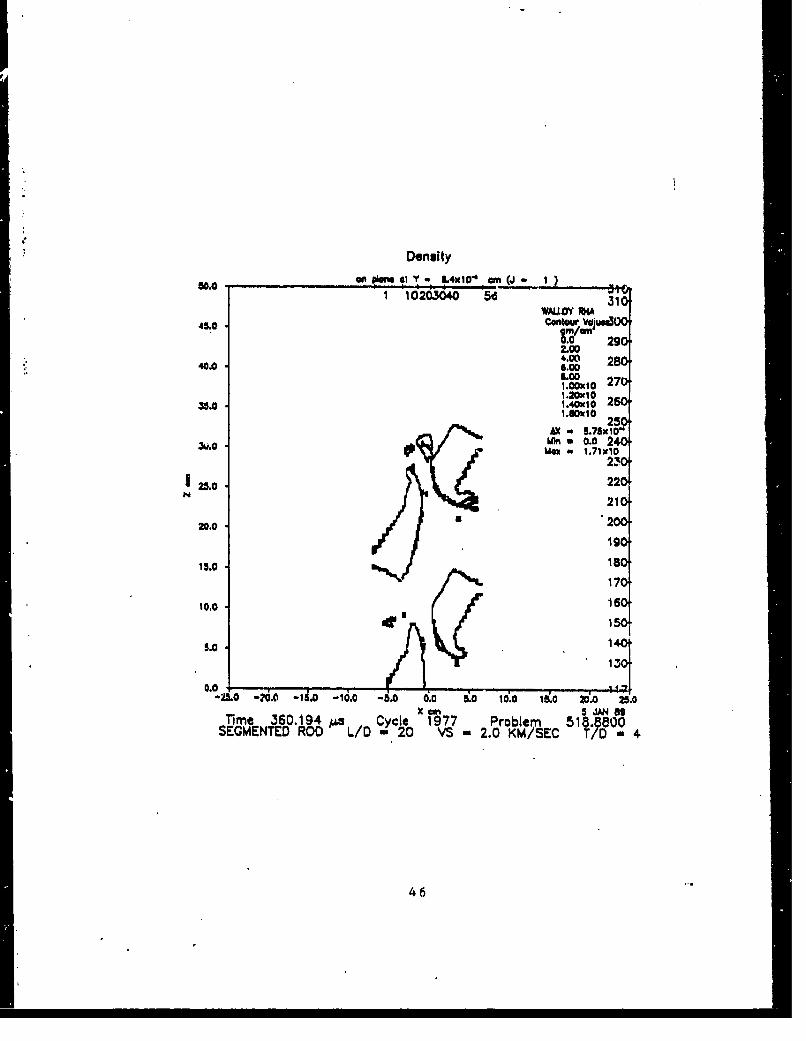
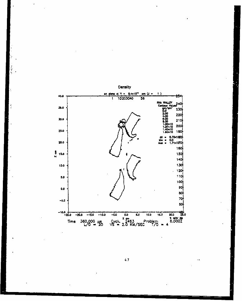
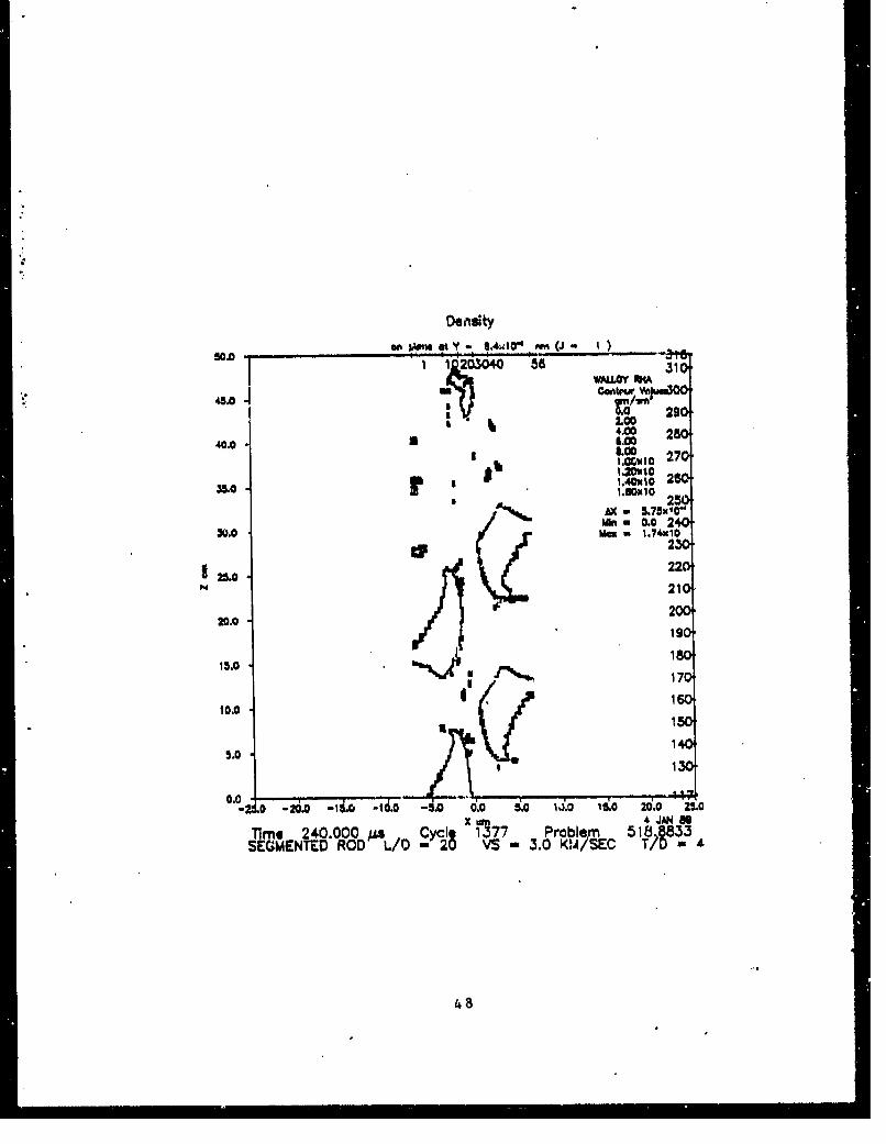
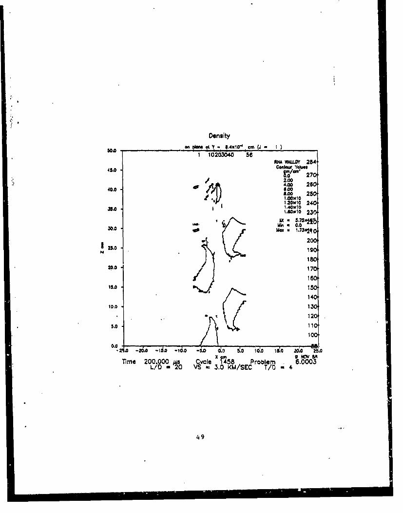
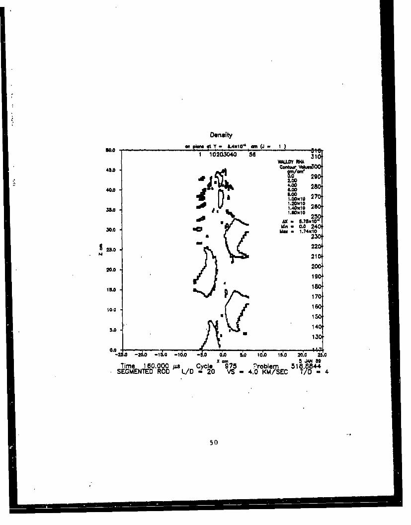
Results for the simulations against the RHA spaced plates for T/D of 4 aresummarized in Table 3. Simulations at a velocity of 1.5 km/s were conducted,however, both the monolithic and segmented penetrators failed to perforate thesecond target plate and are therefore not included. Table 3 shows higherresidual mass for the segmented penetrator at all striking velocities. The datapresented in Table 3 shows the greater the striking velocity, the greater theincrease in residual mass. Figures 11 and 12 show velocity histograms andcontour plots for the segmented penetrator at a velocity of 2.0 km/s. As withthe simulation for the T/D of 2 case at a velocity of 1.5 km/a, individual
3
segment interactions occur which lead to the misalignment of segments. At 3km/s, move of the lead segment is eroded before any interaction occurs, seeFigure 13. In Figure 13, what appears to be a single seqment is a fraction ofthe preceding segment and the subsequent segment. The alignment of the segmentsis less severely affected, see Figure 14. Segment interactions are also observedwell after perforation of the second target plate, leading to severe misalignmentof the segments, see Figure 15. At 4 km/s the lead segment is almost entirelyeroded before interactions occur, see Figure 16. In Figure 16, what appears tobe a single lead segment is the almost entirely eroded second segment beingimpacted by the third segment.
TABLE 3. Residual Mass of Monolithic and Segmented Rod*(N-5, S/D-1) against T/D-4 Spaced Plates
Striking Striking Segmented Segmented Monolithic MonolithicVelocity Energy Residual Residual Residual Residual(km/s) (MJ) Mas Mass tame) Enorav (MJ)
2.0 0.548 18.4 0.0018 14.6 0.00033.0 1.233 68.6 0.250 58.1 0.1864.0 2.192 99.9 0.725 62.0 0.413
The interactions between segments for both T/D of 2 and 4, suggest a spacingof I D is not optimum. The effect of segment spacing on performance for theT/D of 4 target has been studied numerically for segment spacing-to- penetratordiameter ratios, S/D, of 4 and 8. No segment interactions occurred inperforating the spaced plate array. However, the two lead segments for the S/Dof 4 case collided well after (t-100 micro-seconds) perforating the second plate.Thýs occurs because the lead segment did not completely erode during perforationof the second spaced plate. Thus the lead segment loses velocity allowingremaining segments to catch up. Table 4 shows the affect of segment spacing onpenetrator performance. Note that as S/D increases the residual ponetrator mr.ssincreases.
TABLE 4. Residual Mass vs Segment Spacing forVs - 4.0 km/u, N - 5, and T/D - 4 Plates
Spacing Residual ResidualDiameter Mass (rma) Enerav (MJ)
none 62.0 0.4131 99.0 0.7254 108.0 0.8648 126.0 0.9851* 129.0 1.183
* 20 Segment Rod
Table 4 also presents the results for a 20 segment projectile with a S/Dof 1. These results suggest that trailing segments, unaffected by impact withthe spaced plates and/or individual segment interactions, retain more kineticenergy than an equivalent monolithic rod. Figures 17 and 18 show velocityhistograms and density contour plots of the 20 segment pinetrator and theequivalent monolithic penetrator. The monolithic penetrator's velocity is
4
- - - -- - -
bi 0
~ NAN
a-4
in L
CIb2 0 8
* N,
& ;~ z- o
p 5~11)
* ~Z
To b
~ 0-
'6?0
C4.
q i
C4
222z
I '- *E I
'0 0 I Ix
I5to
S4
Cl q
oN
211 6
SZ
I,, WD Za
ft 04
WDZo
eggs qpoM
Ct
2 r!
ý- C
0
7i 7
al Z 7
C1
4~E -n
-!L
ui2
0
2w Z
EI ILI
q ET~ W
wo
.~WU
E *t
~~Aau J
z0
CtC
In
we Z
9 BP ýiR 8 g 9A 9 iANN- - - - - - - - - -3t
~04
0000
ob
S I I-
Ct q II2~ 10
CN N 0
LISI fl
q 0. lo ~ S
- I -I~ dZ
dI.C
II
£w Z
C~4 - - - - - - -
.~ge 2
Fl , C
IIl
V.u
04,
AM A 1 1 a1 q C C C
UlU
-t Es.-
12
2 b
I. "
tQ .2 ' , ,-i,
2. V
US
,~E (A•-
-!
S• M I I
10
0c
N -
ro
lugA
we Z 13
;0; ~~g
rio
~: i...~44j lE"
9 LU
niu
~~~i~w o Z i
MAW
- 0j
ba
U-- 0
Cos-
AV
II
Wo Z I
14
To 7
-l
Euli
C4C
0-x4
~ C17
PjI0S Q SO-
On
too o OOOO~ OQ0Z
N _______________ Nor
o9wr2of2p2 Q
9., ~ 4 'RN
~~C14
mug ~.to~~to
Cth
at
15
, ,, - - - - - - -
LU)
"I .q Ij.
- .0
q "L a•U J
isa -4 u0 r
11 on
.~w . N . • . . .- . .- ..- .- .
_ 'i,---
in 0.0
q q q q O. • Q I II
,66
wu2S:5i
Cl Eu
_ _ _ _ _ _ _ _ _ _ __q 0. t *
~ N Z6
*a C .
z.i00
oo
Ni 040C4C-c-
~ a ~22Y.
q U 4 7
ml.l
EuO
v N
Z, )~aI17
IIW) n 0 CN CN4NN CJlC14~~C - -
'- IN
w we
La L
UNU
000
_ _ _ _ _ _ _ _ _ __?_ _ _ _ _ _ q q ~ qf
wo Z18f
Coo
R o o.'1 ,,A
To b
, q
_ _ C4 _ _ _ __• N _ _ _
34c
c q qt c q q C o cAq
wtz in
Tou__ _ _ _ _ _ _ _ _ _ _ _ _ x
~~viN~~C N 4N 4
9-19
~ITS
2156
o IN
-W q0W pi
_ _ _ _ _ _ _ _ _ _ _ o >
q a a q~ Q q q qZ
2 0 II-emu
_ _ _ _ _ _ _ _ _ _ _ _ _ _ _ _ _ _ _ _ _ _ _ E * )
N"C'4"N.,43 Y.
vi ~ InjIII to
:7 w~. 6 q** --
co z
1'" 9
wo Z 20
.,4 0 ot o o a.,. . -
E C.)e °3, IF J - e
LU,
- N .. - "
kn 0
I-(-I
E- -I . , : .O
LvCl
ra
q0
q C !. q q q t q IA
Ia a ' "2
(N N NN N N N ~C14N - --- - ~- - - . -0
A. 5x
.u Ct
'iiivq ol -
100
S 0
mW 22
0o 0
reduced while perforating the spaced plate array, while trailing segmentsunaffected by interactions retain their initial striking velocity. Table 4 showsa 108 percent improvement in residual mass over the equivalent monolithic rod.The improvement in residual mass of the 5 segment penetrator with an S/D of 8over the equivalent monolithic rod is 103 percent.
4. CONCLUSIONS
A number of 3-D simulations have been conducted to determine the performanceof segmented rods impacting spaced plate arrays. The performance of segmentedrods is characterized based on residual mass and kinetic energy. In general,segmented rods outperform their monolithic counterparts for the spaced platearrays studied at velocities above 2 km/s. The increase in performance isenhanced for thick target plates. Furthermore, the simulations show thatincreasing the spacing between segments increases performance. It is desirable,though not always practical, for spacing to be such that every segment acts asan independent penetrator. Finally, it should be noted that increasing thenumber of segments increases the residual mass and kinetic energy. The increasein performance derived from a greater number of segments is greater than theincrease derived from increased segment spacing.
23
LIST OF REFERENCES
1. Kucher, V. "Multiple impacts on Monolithic Steel", Ballistic ResearchLaboratory Technical Report ARBRL-TR-02406, April 1982.
2. do Rosset, W. S. and Kimsey, K. D., "Calculation of Multiple Copper RodImpacts on Steel Targets", Proc. Ninth International Symposium on Ballistics,Shrivenham, U. K., April 29-30, May 1, 1986.
3. Scheffler, D. R.,"2-D Computer Simulations of Segmented Penetrators",Ballistic Research Laboratory Technical Report, BRL-TR-3013, July 1989.
4. Sedgwick, R. T., Waddell, J. L., and Wilkinson, 0. M., "High Velocity LongRod Impact: Theory and Zxperx..ment", Proc. Tenth International Symposium onBallistics, San Diego, October 1987.
5. Charters, A. C., "The Penetration of Rolled Homogenous Armor by Continuousand Segmented Rods at High Velocity: Theory and Experiments", General ResearchCorporation Technical Report CR-86-1031, April 1986.
6. Charters, A. C., "The Penetration of Rolled Homogenous Armor by Continuousand Segmented Rods at High Velocity: Theory and Experiments", General ResearchCorporation Technical Report CR-87-1008, December 1986.
7. Charters, A. C., and Manna, T. L., "Armor/Anti-armor Program: AdvancedPonetrator Concepts Evaluation Program", General Research Corporatimn briefingpackage presented at the DARPA Armor/Anti-Armor Executive Steering Committee,Arlington, Virginia, August 25, 1987.
8. Charters, A. C., and Manna, T. L., "Armor/Anti-armor Program: SecondQuarterly Review", General Research Corporation briefing package presented atthe DARPA Impact Physics Team Second Quarterly Review, Lawrence LivermoreNational Laboratories, October 14-15, 1987.
9. Bell, L. P., "Evaluation of Segmented and Solid Projectiles DuringHypervelocity Flight and Impact", Arnold Engineering Development Center TechnicalReport AEDC-TRS-87-V6, March 1987.
10. Matuska, D. A. and Osborn, J. J.,"HULL Technical Manual", vol I, OrlandoTechnology Incorporated, 1986.
11. Matuska, D. A. and Osborn, J. J.,"HULL Users Manual", vol 11, OrlandoTechnology Incorporated, 1986.
12. Hancock, J. W., and Mackenzie, A. C., J. Mech. Phys. Solids, 24, 147.
13. Kohn, B. J., "Compilation of Hugoniot Equations of State", Air Force WeaponsLaboratory Technical Report AFWL-TR-69-38, April 1969.
14. Wilkins, M. L., in B. Adler et al. (Eds.), Methods in Computational Physics,Academic Press, New York, 1964.
15. Nicholas, T., "Dynamic Tensile Testing of Structural Materials Using a SplitHopkinson Bar Apparatus", Air Force Wright Aeronautical Laboratories TechnicalReport AFWAL-TR-80-4053, October 1980.
24

APPENDIX A - KEEL Input Data
25

KEEL Input For Monolithic Penetrators, Into T/D-2 Spaced Plates
KEEL PROBLEM 5.0000*NM-3 AIR-i WALLOY-2 RHA-3
DIMEN-3 VISC-1 FLUXER-3 STRESS-iIMAX-51 JMAX-31 KMAX-241 IQ-50 JQ-30 KQ-240FAIL-i STRAIN-i REZONE-0NSTN-2 NOP-2000AREF-.TRUE. BREF-.FALSE. FREF-.FALSE.LREF-.FALSE. RREF-.FALSE. TREF-.FALSE.HEADERL/)) - 20 VS - 1.5 KM/SEC T/D - 2
MESHCONSTANT SUBORID NX-30 XO-2.5 XMAX-2.5 RXNEG-i.i RXPOS-i.1
XOLJM-.O.42045 XMLIM-4.g8g57NY-i5 YO-O.0 YMAX-2.6 RYPOS-1.1YOLIM-0. YMLIM-9,0g078NZ-241 Z0--21.0 ZMAX-39.25 RZNEG-1.O
RZPOS-1.0ZOLIM--2i.0 ZMLIM-39.25
GENERATEPACKAGE WALLOY W-1.GE5
CYLINDER XC-0.0 YC-0.0 ZB--20. ZT--..0. RADIUS-.6PACKAGE AIR W-1.5ES
CYLINDER XC-O.0 YC-0.0 ZB--1.0E20 ZT--20. RADIUS-.5PACKAGE RHA
BOX XI-m.8.0 X2-8.0 Y1-0.0 Y2-8.0 Z1-O.0 Z2-2.0XCO-0.0 YCC-0.0 ZCC-0.88803ANGLB-60
* PACKAGE RHABOX XIina..0 X2'.8.0 Y1.a0.0 Y2-8.0 Z1-0.0 Z2-2.0XCC-0.O YCC-0.0 ZCC-15.02803ANGLB-60
PACKAGE AIR W-1.0E4 BOX FILLSTATION XS-0. YS-0. ZL-0.
XS-0. YS-0. ZL--20.END
26
KEEL Input For Segmented Penetrator, Into T/D -2 Spaced Plates
KEEL PROBLEM 5.0004NM-3 AIR-i WALLOY-2 RHA-3DIMEN-3 VISC-1 FLUXER-3 STRESS-iIMAX-61 JMAX-31 KMAX-273 IQ-50 JQ-30 KQ-272FAIL-i STRAIN-1 REZONE-0NSTN-2 NOP-2000AREF-.TRUE. BREF-.FALSE. FREF-.FALSE.LREF-.FALSE. RREF-.FALSE. TREF-.FALSE.HEADERL/D -20 VS-I1.5 KM/S T/D -2
MESHCONSTANT SUBORID NXm30 XO-2.S XMAXm2.5 RXNEGml.l'RXPOSmi.1
XOLIM--8.42045 XMLIM-4.98g67NY-~iS YO-0 .0 YMAX-2 .5 RYPOS-1 .1YOLIM -0. YMLIM -9.09078NZ-273 Z0--29.0 ZMAX-39.25 RZNEG -1.0
RZPOS-1 .0ZOLIM--29.0 ZMLIM-39.25
GENERATE-PACKAGE WALLOY W-I.5E5
CYLINDER XC-O.0 YC-0.0 ZBm-4. ZT-0.0 RADIUSm.6PACKAGE AIR W-1.2E6
CYLINDER XC-0.0 YCm0.0 Z13-8. ZTm-4. RADIUS-.5PACKAGE WALLOY W-1.5ES
CYLINDER XC-0.0 YC-0.0 ZB--10. ZT-0. RADIUSUM.6PACKAGE AIR W-1.6E5
CYLINDER XC-0.0 YC-0O.0 ZB--12. ZT--10. RADIUS-.6PACKAGE WALLOY W-1.6E5
CYLINDER XC-0.0 YC-0.0 ZB--18. ZT--12. RADIUS-.5PACKAGE AIR W-1.5ES
CYLINDER XC-0.0 YC-0.0 ZB-.18. ZT--18. RADIUS-.5PACKAGE WALLOY W-1.6E5
CYLINDER XC-0.0 YC-0.0 Z13-22. ZT--18. RADIUS-.5PACKAGE AIR W-1.SES
CYLINDER XCm-0.0 YO.-0.0 ZB-*-24, ZT--22. RADIUS-.5PACKAGE WALLOY W-1.5E5
CYLINDER XC-0.0 YC-0.0 ZB-.28. ZT--24. RADIUS-.5.PACKAGE AIR W-1.5E5
CYLINDER XC-0.0 YC-0.0 ZI3--1.0E20 ZT--28. -RADIUS-.5PACKAGE RHA
BOX X1-8.0 X2-8.0 Y1-0.0 Y2-8.0 Z1-0.0 Z2-2.0XCC-0.0 YCC-OA) ZCC-0.88803ANGLB-80
PACKAGE RHABOX X1-8.0 X2-8.0 YI-0.O Y2'-8-0 Z1-0.O Z2-2.0XCCrO.0 YCCu'0.0 ZCCa.16.02003ANGLBm6O
PACKAGE AIR W-1.0E4 BOX FILLSTATION XS-'0. YS=O. ZL-0.
XS-0. YS-0. ZL--28.END
27
* ~KEEL Input For Monolithic Penetrators Into T/Du-4 Spaced Plates
KEEL PROBLEM 8.0001NMý3 AIR-i WALLOY-2 RHA-3DIMEN-3 VISCami FLUXER-"3 STRESS-IIMAX-58 JMAX-33 KMAX-284 IQ-65 JQ-32 KQ-283FAIL-., STRAIN-i REZONE-0NSTN-2 NOP-2000AREF-.TRUE. BREF-.FALSE. FREF-.FALSE.LREF-.FALSE. RREF-.FALSE. TREF-.FALSE.HEADERL /D - 20 VS - 1.5 KM /SEC T/D - 4
MESHCONSTANT SUBORID NX-30 XO-2.5 XMAX-2.5 RXNEG-1.1 RXPOS-1.i
XOL[Mm--.99583 XMLIM-6.g9683NY-iS YO-0.0 YMAX-2.8 RYPOS-1.1YOLIMm0. YMLIM-i0.85g85
* ~NZ-2g8 Z0--21.0 ZMAX-47.26 RZNEO-1.0RZPOS- 1.0
ZOLIM--21.0 ZMLIM-50.GENERATE
PACKAGE WALLOY W-1.05ECYLINDER XC-0.0 YC-0.0 ZB--20. ZT--0.0 RADIUS-.5
PACKAGE AIR Wm1.5E5CYLINDER XC-O.0 YC-0.0 ZB--i.0E20 ZT--20. RADIUS-.6
PACKAGE RHABOX X1-10.0 X2-10.0 Y1-0.0 Y2-10.0 Z1-0.0 Z2-4.0XCC-i.7321 YCC-0.0 ZCC-3.88803ANGLB-80
PACKAGE RHABOX X1-10.0 X2-10.0 Y1-0.0 Y2-10.0 ZI-0.0 Z2-4.0XCCmi.7321 YCC-0.0 ZCC-22.02603ANGLB-80
PACKAGE AIR W-1.0E4 BOX FILLSTATION XS-0. YS-0. ZL-0.
XS-O. \'S-O. ZL--20.END
28
KEEL Input For Segmented Penetrators Into T/D -4 Spaced Plates
KEEL PROBLEM 518.88NM-3 AIR-i WALLOY-2 RHA-3DIMEN-3 VISC-I FLUXER-3 STRESS-iIMAX-68 JMAXa-33 KMAX-316 IQ-53 JQ-32 KQ-315PAIL-I STRAIN-i REZONE-ONSTN-2 NOP-2000AREF-.TRUE. BREF-.FALSE. FREF-.FALSE.LREF-.FALSE. RREF-.FALSE. TREF-.FALSE.HEADERSEGMENTED ROD L/D - 20 VS - 2.0 KM/SEC T/D - 4
MESHCONSTANT SUBGRID NX-30 XO-.2.5 XMAX-2.5 RXNEG-i.1 RXPOS-1.1
XOLIM-..6.99583 XMLIM-8.gg583NY-iS YO-0.0 YMAX-2.5 RYPOS-1.1YOLIM-.0. YMLIM-i0.85g85NZ-316 ZO--2g.0 ZMAX-50. RZNEG-1.O
RZPOS-i.OZOLIMý-29.0 ZMLIM-50.
GENERATEPACKAGE WALLOY W-2.0E5
CYLINDER XC-O.0 YC-0.0 ZB--4. ZT-O.O RADIUSWU,5PACKAGE AIR W-2.0E5
CYLINDER XC-0.O YC-O.O ZB--8. ZT-.4. RADIUS-.5PACKAGE WALLOY W-2.0E5
CYLINDER XO-O.O YC-O.O ZB--10. ZTm-6. RADIUSm.6PACKAGE AIR W-2.05S
CYLINDER XC-O.O YC-OO ZB.--I2. ZT-m-iO. RADIUS-.5PACKAGE WALLOY W-2.0E5
CYLINDER XC-0.0 YC-O.O ZB--18. ZT-.12. RADIUS-.5PACKAGE AIR W-2.OE5
CYLINDER XC-O.0 YC-0.O ZB--18. Z'r--is. RADIUS-.6PACKAGE WALLOY W-2.0E5
CYLINDER XC-OO0 YC-O.O ZB--22. ZTý-.18. RADIUS-.6PACKAGE AIR W-w2.OES
CYLINDER XC-O.O YC-0.O ZB--24. ZT--22. RADIUS-.5PACKAGE WALLOY W-2.0E5
CYLINDER XC-OO0 YC-O.O ZB--28. ZT--24. RAD[US-.5PACKAGE AIR W-2.0E5
CYLINDER XC-D.O YC-O.O ZB--i.0E20 ZT-..28. RADIUS-.5PACKAGE RHA
BOX X--.1O.O X2-10.0 Y1-0.0 Y2-10.0 Z1-0.0 Z2-4.0XCC-1.7321 YCC-O.O ZCC-3.88603ANGLB-80
PACKAGE RI4ABOX X1-101.0 X2-."10.0 Y1-0.0. Y2-"10.0 ZIv-0.O Z2-4.0XCC-1.7321 YCC-O.O ZCiCm22.02603ANGLB-e0
PACKAGE AIR W-1.0E4 BOX FILLSTATION XS-O. YS-O. ZL-O.
XS-O. YS-O. ZL--28.END -
29
KEEL Input For S/D-4 Segmented Penetrator Into T/D-4 Spaced Plates
KEEL PROBLEM 7.0001NM-3 AIR-I WALLOY-2 RHA-3DIMEN-3 VISC-1 FLUXER-3 STRESS-iIMAX-68 JMAX-33 KMAX-348 IQ-55 JQ-32 KQ-347FAIL-i STRAIN-i REZONE-0NSTN-2 NOP-2000AREF-.TRUE. BREF-.FALSE. FREF-.FALSE.LREF-,FALSE. RREF-.FALSE. TREF-.FALSE.HEADERSEGMENTED ROD L/D - 20 VS - 4.0 KM/SEC T/D - 4
MESHCONSTANT SUBORID NX-30 XO-2.5 XMAX-2.5 RXNEG-i.1 RXPOS-1.i
XOLIM--8.9g583 XMLIM-6.9g583NY-15 YO-"0.0 YMAX-2.5 RYPOS-il1YOLIM-0. YMLIM-10.85985NZ-348 ZO--37.O ZMAX-50. RZNEG-1.0
RZPOS-i .0ZOLIMm-37.0 ZMLIM-50.
GENERATEPACKAGE WALLOY W-4.OES
CYLINDER XC-0.O YC-O.0 ZB--4. ZT-0.0 RADIUS-.5PACKAGE AIR W-4.0E5
CYLINDER XC-0.0 YC0.0. ZB--8. ZT-4. RADIUS,5PACKAGE WALLOY W-4.OE6
CYLINDER XC-0.0 YC-0.O ZB-.12. ZT--8. RADIUS-.5PACKAGE AIR W-4.OES
CYLINDER XC-0.0 YC-0.0 ZB--16. ZT--12. RADIUS-.SPACKAGE WALLOY W-4.0ES
CYLINDER XC-0.0 YC-O.0 ZB--20. ZT--16. RADIUS-'.6PACKAGE AIR Wý4.OE5
CYLINDER XC-0.0 YC-0.0 ZB--24. ZT--20. RADIUS-.6PACKAGE WALLOY W-4.0E5
CYLINDER XC-0.O YC-0.0 ZB--28. ZT--24. RADIUS-u.SPACKAGE AIR W-4.0E5
CYLINDER XC-0.O YC-O.0 ZB--32. ZT--28. RADIUS-.5PACKAGE WALLOY W-4.0E5
CYLINDER XC-O.O YC-0.O ZB--38. ZT--32. RADIUS-.5PACKAGE AIR W-4.OES
CYLINDER XC-0.O YC-0.O ZB-.i.0E20 ZT--38. RADIUS-.5PACKAGE RHA
BOX XI--10.0 X2-10.0 Yi-0.0 Y2-10.0 Z1-0.0 Z2-4.0XCC-1.7321 YCC-0.0 ZCC-3.86603ANGLB-60
PACKAGE RHABOX X1-10.0 X2-10.0 Yi-0.0 Y2-10.0 ZJ-0.fl Z2-4.0XCC-1.732i YCC-0.0 ZCC-22.02603ANGLB-60
PACKAGE AIR W-l.0E4 BOX FILLSTATION XS&aO. YSO0. ZLO0.
XS-O. YS-0. ZL--52.END
30
KEEL Input For S/D-8 Segmented Penetrator Into T/D=4 Spaced Plates
NM-3 AIR-I WALLOY-2 RHA-3DIMEN-3 VISC-i FLUXER-3 STRESS-IIMAX-58 JMAX=33 KMAX-412 IQ-55 JQ-32 KQ-411.FAIL-i STRAIN-i REZONE-0NSTN-2 NOP-2000AREF-.TRUE. BREF-.FALSE. FREF-.FALSE.LREF-.FALSE. RREF-.FALSE. TREF-.FALSE.
* HEADERSEGMENTED ROD L/D - 20 VS - 4.0 KM/SEC T/D - 4
MESHCONSTANT SUBGRID NX-30 XO-2.5 XMAX-2.5 RXNEG-i.i RXPOS-1.i
XOLIM--8.99583" XMLIM-8.9g583NY-15 YO-O.0 YMAX-2.5 RYPOS-i.iYOLIM -0. YMLIM -iO.8508SNZ-412 Z0--53.0 ZMAX-50. RZNEG -1.0
RZPOS-i .0ZOLIM--53.0 ZMLIM-60.
GENERATEPACKAGE WALLOY W-4.0E5
CYLINDER XC-0.0 YC-0.0 ZB--4. ZT-0.0 RADIUS-.6PACKAGE AIR W-4.OE5
CYLINDER XC-O.O YC-0.0 ZB--12. ZT--4. RADIUS-.5PACKAGE WALLOY W-4.OES
CYLINDER XC-0.0 YC-O.0 ZB--18. ZT--12. RADIUS-.5PACKAGE AIR W-4.0ES
CYLINDER XC-0.O YC-0.0 ZB--24. ZT--18. RADIUS-.6PACKAGE WALLOY W-4.0E5
CYLINDER XC-O.0 YC-0 0 ZB--28. ZT--24. RADIUS-.5PACKAGE AIR W-4.0E5
CYLINDER XC-0.0 YC-O.0 ZB--38. ZT--28. RADIUS-.5PACKAGE WALLOY W-4.0E5
CYLINDER XC-0.O YC-0.0 ZB--40. ZT--38. RADIUS-.5PACKAGE AIR W-4.0E5
CYLINDER XC-0.O YC-0.O ZB--48. ZT--40. RADIUS-.5PACKAGE WALLOY W-4.OES
CYLINDER XC-0.O YC-0.0 ZB--52. ZT--48. RADIUS-.5PACKAGE AIR W-4.OES
CYLINDER XC-0.O YCiv0.0 ZBý--.0E20 ZT--52. RADIUS-.5PACKAQE RHA
BOX X1-10.0 X2-10.0 Y1-0.0 Y2-10.0 ZI-0.0 Z2-4.0XCC-1.7321 YCC-0.0 ZCC-3.86003ANGLB-60
.PACKAGE RHABOX X1-10.0 X2'-10.0 Y1-0.0 Y2-10-0 ZI-0.0 Z2-4.0XCC-1.7321 YCC-0.O ZCC-22.02803ANGLB-60
PACKAGE AIR NW-i.0E4 BOX FILLSTATION XS-0. YS-O. ZL-0.
XS-O. YS-0. ZL--52.END
3 1
KEEL Input For 20 Segment S/D -1 Penet~rtor Intoo T/D -4 Spaced Plates
KEEL PROBLEM 8.0000NM-3 AIR-I WALLOY-2 RHA-3DIMEN-3 VISC-1 FLUXER-3 STRESS-IIMAX-68 JMAX-33 KMAX-380 IQ-56 JQ-32 KQ-359FAIL-i STRAIN-i REZONE-0NSTN-2 NOPm2000AREF-.TRUE. BREF-.FA LSE. FREF-.FALSE.LREF-.FALSE. RREF-.FALSE. TREF-.FALSE.HEADERSEGMENTED ROD L/D - 20 VS m 4.0 KM/SEC T/D - 4
MESHCONSTANT SUBGRID NX-30 XO-2.S XMAX-2.6 RXNEG-1.1 RXPOS-1.1
XOLIM-..6.g9583 XMLIM-8.g9583NY-15 YO-0.0 YMAX-2.5 RYPOS-1.1YGLIM-0. YMLIM-10.85g85NZ-380 ZO--40.0 ZMAX-50. RZNEG -1.0
RZPOSm1.0ZOLIM--40.0 ZMLIM-50.
GENERATEPACKAGE WALLOY W-4.0E5
CYLINDER XC-0.0 YC-0.0 ZB--1. ZT-0.0 RADIUS-.6PACKAGE AIR W-4.0E5
CYLINDER XC-O.0 YC-0.0 ZB--2. ZT--i. RADIUS-.6PACKAGE WALLOY Wm4.0E5
CYLINDER XC-0.0 YC-0.0 ZP--3. ZT-2. RADItJS-.6PACKAGE AIR W-4.0E5
CYLINDER XC-0.0 YC-0.0 ZB--4. ZT-.3. RADIUS-.6PACKAGE WALLOY W-m4.OES
CYLINDER XC-0.0 YC-0.O ZB~-S. ZTa-4. RADIUSm.5PACKAGE AIR W.-4.0E5
CYLINDER XC-0.0 YC-0.0 ZBwu.6. ZT-5. RADIUS-.5PACKAGE WALLOY W-4.0E5
CYLINDER XC-0.0 YC-0.0 ZB.--7. ZT--8. RADIUS-.5PACKAGE AIR W-4.0E5
CYLINDER XC-0.0 YC-0.0 ZB--8. Z'r-7. RADIUS-.SPACKAGE WALLOY W-4.OE5
CYLINDER. XC-0.0 YC-0.O ZB--9. ZT-8. RADIUS-.5PACKAGE AIR W-4.0E5
CYLINDER XC-0.0 YC-0.0 ZBu-i10. ZT--Q.. RADIUS-.5PACKAGE WALLOY W-4.0EF5
COYLINDER XC'.-0.0 YC-0.0 ZBm-11. ZTm-10. RADIUS-S'PACKAGE AIR W-4.0E5
CYLINDER XC-0.0 YC-0.0 ZB--i2. ZT--il. RADIUS-.5PACKAGE WALLOY W-4.0E5
CYLINDER XC-0.0 YC-0.0 ZBi-i13. ZT--12. RADIUS-S5PACKAGE AIR W-4.0E5
CYLINDER XO-0.0 YCwuO.O ZB-i14. ZT--13. RADIUS-.5PACKAGE WAALLOY W-4.0E5
'YLINDER XC-0.0 YC-0.0 ZB--i5. ZT-.14. RADIUS-u.5PACKAGE AIR W-4.0ES
CYLINDER XC-O.0 YC-0.0 ZB--16. ZT--15. RADIIUS-.5PACKAGE WALLOY W-4.OE5
32
CYLINDER XC-O.O YC-O.O ZB--17. ZT--lb. RADIUS-.5PACKAGE AIR W-4.OES
CYLINDER XC-O.O YC-O.O ZB--18. ZT--17. RADIUS-.5PACKAGE WALLOY W-4.0E6
CYLINDER XC-O.O YC-O.O ZBon-19. ZTm-18. RADIUS-.6PACKAGE AIR W-4.0ES
CYLINDER XC-O.O YC-O.O ZB--20. ZTý--I. RADIUS-.5PACKAGE WALLOY W-4.0ES
CYLINDER XC-O.O YC-O.O ZB--21. ZT--20. RADIUS-.5PACKAGE AIR W-4.OE6
CYLINDER XC-O.O YC-O.O ZB--22. ZT--21. RADIUS-.6* PACKAGE WALLOY W-4.0E5
CYLINDER XC-O.O YC-O.O ZB--23. ZT--22. RADIUS-.5PACKAGE AIR W-4.0ES
CYLINDER XC-O.O YC-O.O ZBý-24. ZT--23. RADIUS-.5PACKAGE WALLOY W-4.OES
CYLINDER XC-O.O YC-O.O ZB-.25. ZT--24. RADIUS-.6PACKAGE AIR W-4.OE6
CYLINDER XC-O.O YC-O.O ZB--26. ZTmm-2J5. RADIUS-.5PACKAGE WALLOY W-4.0E5
CYLINDER XC-O.O YC-O.O ZB--27. ZT--28. RADIUS-.6PACKAGE AIR W-4.OES
CYLINDER XC-O.O YC-O.O ZB--28. ZT--27. RADIUS-.6PACKAGE WALLOY W-4.OE5
CYLINDER XC-O.O YC-0.O ZB--29. ZT-.'28. RADIUS-.5PACKAGE AIR W-4.OES
CYLINDER XC-O.O YC-O.O ZB--30. ZT-..29. RADIUS-.5PACKAGE WALLOY W-4.OES
CYLINDER XC-O.O YC-O.O ZB--31. ZT--30. RADIUS-.5PACKAGE AIR W-4.0E5
CYLINDER XC=O.O YC-O.O ZB--32. ZTm--31. RADIUS-.5PACKAGE WALLOY W-4.0E5
CYLINDER XC-O.O YC-O.O ZB--33. ZT-32. RA DIU S-.6PACKAGE AIR W-4.0ES
CYLINDER XC-O.O YC-O.O ZB--34. ZT--33. RADIUS-.5PACKAGE WALLOY W-4.0E5
CYLINDER XC-.O. YCOO. ZB--36. ZT--34. RADIUS-.6PACKAGE AIR W-4.OE5
CYLINDER XC-O.O YC-O.O ZB--36. ZT--36. RA DIU S-.6PACKAGE WALLOY W-4.OES
CYLINDER XC-O.O YC-O.Q ZB--37. ZT--30. RADIUS-,5PACKAGE AIR W-4.OES
CYLINDER XC-O.O YC-O.O ZB--38. ZT--37. RADIUS-.5PACKA GE WA LL OY W-4.OE6
* CYLINDER XC-O.O YC-0.O ZB--39. ZT--38. RADIUS-.6PACKAGE AIR W-4.0E5
CYLINDER XC-O.O YC-O.O ZB-lI.0E20 ZT--39. RADIUS-.5PACKAGE RHA
* ~BOX X1-10.0~ X2-10.0 Y1-O.O Y2-10.0 ZI-O.O Z2-4.0XCC-1.7321 YCC-O.O ZCC-3.86603ANGLB-60
PACKAGE RHABOX X1-10.0 X2-10.0 Yl-0.O Y2-10.0 Z1-O.O Z2-4.0XCC-1 .732 1 YCC-O.O ZCC-22.02803
33
ANGLB-80PACKAGE AIR W-1.0E4 BOX FILL
STATION XS-0. YS-0. ZL-0.XS--0. YS-0. ZL--40.
END
34
APPENDIX B - Material Properties
35
APPENDIX B
Material Propertieb and Equation of State Dat&
Ambient deusity (g/cc) 7.83 6T,3
Ambient sound speed (cm/i) 4.61ob 4,0e6
Shock velocity/put•cle velocity slope 1.73 1.268
Initial Grnseieen ratio 1.67 1.43
Minimum Premiere (dynem/cmeO2) *.,0020 .10.09
Poion'4 rtio 0.26 0.3
Atomic weight 58,86 184.
D*Bye'e temperature (K) 385 270
Vapor coefcient 0.26 0.2
Ambient eneru per unit mum (erp/g) 0.0 0,0
Ambient melt energy per unit mum (erp/g) 7.040 4,7700
Fusion energ7 per Unit mam (Grp/g) 2.74.0 1.34o0
Sublimation energy per unit mum (oerl/g) 74.209 46,5
Ambient vaporisation energy per unit mum (elrgm/g) 22.4,09 13.09
Ambient energy per unit mass at end of vaporisation 96.3i0 68.400(eOrv/g)
Initial yield strength (dyaei/cmee2) 16.e0 20.e09
Saturalaon yield strength (dynem/cm,•2) S1e0 20.e@
rIustic strain ai saturation yield trengith 0,3 0.3
Yield strength ratio for irst point on thermal 0.9 0.9softennlg curve
Energy ratio for first point on thermal soft4mnitg 0.6 0.6curve
Yield strength ritio for second point on thernial 0.9 0.9softening curve
Energy ratio for second point on thermal moftuing 0.6 0.8Scurve
Second coefficient in Hugoniot proesmre curve 4.21968.12 4.6987.12(dynes/cm'e2)
Third coelcient in Hugoniot pressure curve 6.12016.12 3.345e12
(dynem/cm-e2)
Ultimate failure stres (dynes/cmeos) 42.eg 1.ebO
Ultimate failure strain 1.78 0.14
36
APPENDIX C - Plots Used For Residual Mass Calculations
37
Den~itym~I.A'.i.4xl0" a ,(J - ! )an. '0 " - " •' - CM' Q
"40A 0102030 W 273RKA WAUJOY
3 5 .0 /6floolu e
Won 250LOO4.00 240
30.0 1.00 ,.o 231.OoxlO,.20xt'o
140 22025.0 1.so mlO 21 .AX ,a S.3xtO"
2in . 000 200
15.0 1 so
N 170
16O
101305.0o 150
1200.0 11
100
-* 1. 00go.
.ZV-. 0.0 4. £R 2Xn I KYV 8
Tie Q30 Cycle 22~01 Problem .004
SEGMENTED ROO A* -LD 20 VS- 1.5 KM/SEC -2
38
Densityn .t Y -. IA4W10- on (J - I)
4010 ¶ 102030 M . 241
Conto•u njUJMfrV" •/•2202.004.0 210
0.100 6.006.00 2001.20M0 190
I.IONO 180
2010 Mai a L730~
150150N 140
130
0 0 50. 120S1`10
---- 5.o 100
390
o~o 80
70d 60
- 2ic , -1d.0 -4.0o -ic.o -11.0 o'a . 0 Io ' oo Is. 5ý oId0o
Y an a MWO a
VO -2C v M .5 KMXSEC T/O - 2
39
Densityan PW t•= ,4, lp 6..0 n(J = I)
1 102030 W SAWAA 273
35.0 ConUr vopuaso
Ao/ 2502!.004.00 240
30.0 1,00 4.00I.Ooxoo 230120x10
25.0 t.14xO220
20.0 Ma a 1.74viO190
15.0 13N I 170
10.0 160
1505.0 14 .0
130
0.0 120
11A0
-5.0 100
"-2i.0 -20.0 -i1.o - od.0 -4.o do i.o0 Io. 15s.o' 2d.0 2..oS x 1. 19 NOV 88
Time 280.000 Cycle, Problem AS)00,5SEGMENTED ROD L/D- 20 ., 2.0 KM/SEC C- 2
40
Density
on Soa1Y.w. 1.4x 10' on(J I)
1 102030 W 241,M4A WA.LOYW.
35.0 clw Pro('o / 2202.004.00 210
30.0 o.006.00 200
4 qfll LOWx 101.20xlO 190
25.0 1 40x1O, t.Sox 1 0 lao
200•0.0 00
15.0 150N 10
13010.0 -120
1105.0 - 100
900.0 .8 o~o 80
70-5.0
6C
-10.0~ --- -I '.0' , , ,,' 1.0.. , , - =-. 0 -20.0 -15.0 -10.0 -5.0 0. 6.0 0.0 15.0 20.0 25.0
X am 86NOYrime 2400800 j~&s Cycle 1654 Problem 510001
L/0. 20 VS - 2.0 KM/SEC T/0 - 2
41
Density
40,0 "- Y- m .41:1 4 " "(J I "1 102030 W 273
Nta WALJ.OY
31.0 Catetw 1 ajiso 6
2.004.00 24030.0 -e 6,00
1.0o910 2301.20N10
25.0i 220j50 1.60MIO 21
A ,- 5.2310"NI4 Eh w- 0.0 20020.0 1 1.74X10
190
S 11.O 180
170
10`0 160
130
5.2110
I -•LO
-10.0S,0 -o.-o -id.o -101.0 51.0 doo i.0 lio 1.0o 2.0 -25.0
X am 9 NOV BeTime 1 60.000 A.s Cycle 928 Problem 5.0D0
SEGMENTED ROD L/D -20 VS 3.0 KM/SEC T/D - 2
42
Density
an ft at Y ,w .4xl0 4 amn( - 1J )40.0 ." .
1 102030 W 241RNA WAL.LOYw€contour Ve.luQ.P3
35.0 flV/am ,0,0 ,v222.004.00 210
30.0 5.00,100 200
1.00K 101.20O)1 19g
25.0 1.40x10l.eOXlO 180
20o.0 M = 1.741# 0
15.015N 140
10.0
100.0 10
-0.0 soI
- -2d.0 -13.0 -10.0 4 1 .0S-oo -5.0 0.0 5'.0 10.0 '. 20.0 25'.0
Xcm 8 NOV88Time 140 000/a3 C 10 824. C Problem 5.0002
L/D -. 20,3.0 K20 C TD 82
43
Density
40.0 On PWII 1 _Y. .4xl0" om (J - I)
1 102030 'M 273RHA WMALL0
U.0 ~C~ntOW !QaJUG12
Val 250
0, 6100 240',:o 1 230
1.20M10254 1.4o0Xi0 220SI1010 21
20.0 wing \ a 0.0 200
15.0 180170
100, 16K, • 150
5.0 10130
.0 ' o120110
-5.0 10090
- .0 -2o.o -14- -Id- 4 - dO o'. o , I', d .0 7 '20'.0 25.0rime 1:20.000 /ps 141c~e P + :roblem '5.0007NVl
SI'GMENTD ROD L/O 0 VS-2 4.0 0M/SEC T/D - 2
44
Density
40.0 !.WM Y. (J1 102030 W 241
WA WALW.Y
35.0 Contou Voju6;3
..0/• 2202.004.00 21030.0 6 I.00
i.00 20025.0 1: 410 X 1,0 s1.2oXIO 1g0
*A , 1,20M 125.0 ,14W 120
M3.0 u .
20.0
0 1.0 1
13010o,0 120
115.010
-10.0 -i'--0
00
-5..0 .0-25.0 -20.0 -17.0 -10.0 4S.0 0.0 i.0 I0.0 15.0 20.0 25.0
X cma 8NOV 88"Time 100 000 g0 Qyc/le 631 Problem 5.0003
LD - 20 VV 4.0 KM/SEC, T/D -2
45
I.
Density
.0o' P= .t Ya L4x10" m(J- I)1 10203040 56 ,1
45.0 2goLaO
40.01.Ooxlo 2701.20xI035g.4mox 260
250X ,- 7Sx10"
30.0~I ,,Mn 0.0 240u0 a -1.71x10
23025.0 220
210
20.0 200
19015.0 180
So~o10 -ri
10
0. U-'-O. -20.0 -15.0 -10.0 -5.0 60. 5.o 1.o 0" 20.0 25.0X CM 5 ,W , 09
Time 360.194 pa Cycle 1977 Problem 518.8800SEGMENTED ROD L/D -. 20 VS - 2.0 KM/SEC T/D - 4
46
Density
df#St V SAW10- I CmJu )40.0 .. ,
I1 020-V40 561 1OO3O4 56 RPA WAUOY •40!
0. .0/mlo 2.30
400 2J0,0 6.003.00 210] .004 l 0t.2�20 20
S.•.0 r 1.40410i.eIo 190
Ax . 5.75kgo20.Min a 0.0
20.0 " .- 1.7149>1
IS
tO 140
5o.0 130
-0.090
- -5.o 70
60
"-2d.0 -20.0 -1,.0 -10.0 -4.0 0.0 .C o'1.0 1 0.0 20.0X aINOVYa
Time 360,000 AS Cyck. 2463 Problem 6.0002iD - 20 VS- 2.0 KM/SEC T/O - 4
47
Density
ati Ma ~Y - 0.4-a 1 mn(J- I
5s I It103O4O 56 W*U.LOY RMu~Owttfw m~us.3o
rO/" 290*LOD
4 2. 040.0* 27
3.01.0 M •ie. -' 1.?4,N10
8220NM 270
25.2Il010
1.4xi 2600
Min0 a--.24
19015.00
1803S= • 170
| , ~160 .i0.0
S150
0. , -2..0 I4. 15.0 20'.0 45.0xl•• 4 JAN av
rimeNT 00s Cycle 1S77 Problem 5188833SEGMENTED ROD LI- 20 VS 3.0 KIA/SEC TD
48
Density
0.0 oOn fiM @t Y , ,A,1,0', (M J- ()1 10203040 56
wrALLDY 28445.0 Conhup !ojuu
4.0 270
40.0 4.0 2608.00 250•
/% .1 .00xtl01,20*10 2 0
35,0 1.64010
AI ,x 5.75,9 ,U0, •m 0.0
30. M= 1.73xjjq
,,25.0 200
180
20.0 70
160
15.0 150
10.0 130,. • 120
1.0 11
0.01-2i.o -26.0 -lio -70.0 -5'A 00. 5.o I0.0 15.0 0 O.0 25.0
Xcm 9 WW PTime 200,00 0•.s Cycle 1458 Problem 6.0003
L/D-2 VS w 3.0 KM/SEC T/1r 4
49
Density10.0a ipigMat Y -lxI.4x60 4 an (J I
1 10203040 56 310
WA.LOY WA
45.0 -oltd Vujuui
of 290
4.00 28040.0 - Is6:O 6.00tox2o 2701.20KI0
I3 %• q 14Ol 260
, o we 5 . 7 , 1 0
3~~Mn*0.0 2 an .4* 230
123.0 - 220210
20.0 20190
15.0 18I
170
10.0 10
5.014
0.0 Tm 1 , ,q , , ,.oi.'0- -20.o -. -i0o 0 -o o ' i.0 20.0 25.o
Time 160000Cycle 975 7roblem 518.0844SEGMENTED ROD LD/0 - 20 VS- 4.0 KM/SEC T/D - 4
50
Domn~ityon a t ,,.Y 9.,,,? ,.on (J. I
.0 .1 10203O4 56
V"• 2704000.o * 00 250
40.0 6.00
61l00 2501.40x10
10. IA : 2.7s 0I
20.00
1-20X17020
35.0 1M 10
m0.0 0 .
20 2000
L 200.0KM/SEC T/1 - 4
51
Denuity
anoP! iseY - AA.X10' am (J.)1 10203040 56
2.0o 320.
40.0 .:00 310.& 3 ,00II1.00i1 3O•0',3010
i .20MI0a ',40%10 290
1.Io0'10
SAx -X 5.75*3#,,to~ • I ,.,.Uln a 0,0
L~260250
240
20.0 230220
15.0 o 210', 20D
10.0 1901 180
5.0 170160.
0.0 -d 4 o4s0o¶ oi7,I~- .0 -,&d.0 ,-Ii.0d.o -d.o d .0,o Io',o lio 20.0 21.0
Time 180.000 pa ýCylo 1351 .Problem 7P001SEGMdENTED ROD L/D -20 VS -4.0 KM/SEC T/D .4.
52
S3 1 11 . .. . . . . . .. .
Densityp.Wm at Y€ .- .4A X o"• - a m QJ - I );
£0.0 - P0A WM.Y 400)
I ~~ccitoiw Yeju"45.0 390
'0"Z'OU 3804,.0U
1.0ow 10
35.0 Leon10 350
Ax *5.75X3~Mlin 0.0
30.0 Ma *1.74M3
32J
20.0 31
25
15.0 27
260
10.0 25240
5.0 230
220,
-2.0 -06. 0l0-0. 22.0.0o -6.0 -4 -;. - -16.' 1o"0Xm' 9 NOV so
Time 290.000 & C ycle 1492 Problem 7.0002SEGMENATD ROD L/D -VS 4.0 K0./EC T/D 4
53
Dlensity
aniet Ym -. 410 IVCM (J I)10.0 . ,,, . 0 , 5
. ite1 0 ,04 5" R
2.00 304.00
40.0 ,o 320', "K 1,00 0iMoo•0,10¶.201110
35.0 I.BoxiO 300
AX 5.75x 2 #Min 0.0
2702_.o 260
25020.0 240
230
15.0 220
o0.0 200
5.0 180170
SEG.0 1~ RO46.1¶. ~0 00 2.-25.0 -2.0 -. o.o i.0 1. 5.0 20.0 2m.0X off 0V Nov u-
Time 170.000 *s C Ycle 1287 Problem 8.000SEGMENTED ROD L/0 20 VS 4.0 KM/SEC T 0 -
54
No of No of
c:,wi,..... .eawA.i)12 Administrator CommanUdudmi.., 1-1,,d) 2 Defense TechnWcu1 Info Center US Army Missil CommendIcmA.d) 2 ATTN: DTIC.DDA ATrN: AMSMI-RD-CS-R (DOC)
Cameron Station Redstone Arsenal, AL 35898-5010Alwkdiria, VA 22304-6145
1 CommanderHQDA ,(SARD.TR) US Army Tonk Automotive CommandWASH DC 20310,0001 ATIN: AMSTA.TSL (lToclcal LIbruy)
Warn, AI 48397.50=0CommanderUS Army Material Command 1 DirectorATIN: AMCDRA-ST US Army TRADOC Andysis Commend5001 isenhower MAvan ATT ATAASLAexandria, VA 2233-3X001 Whift Suads Milib RIMa, NM 86002-5502
Commander P=. w 1 CommandantUS Army Laboratory Command US Army Inbfury SchoolATMN: AMSLC.DL ATTN: ATSH.CD (Security •'4M.)Adephi, MD 20783.1145 P SnBonin& GA 3190S-566
2 CommanderMe"o,., MW• 1 ConmmndantArmament RD&, Cenwe US Army Indeomy SchoolUS Army AMCCOM ATMN: ATSH-CDCS0ORAW'N: SMCAR-MSI Fort BeDnn. GA 31905-5660Plcutiy ArsoaMl, 0I 07806-50WI (C-'i. ')1 Tin Rand COIPOIMIC
2 Commander P.O. Box 2138Armamet RD&] Cen. San Monicka CA 90401-2138US Army AMCCOMAMlN: SMCAR-TDC .1 Air Pace Amament iLabm r yPicatinny Arenl, Wi 07806.5000 ATTN: A. ATLDLODL
El& AF, IL 32542-5000I Directo
knot Weapons LaboratoryAnument RIME Cen D, USAMSAA-US Army AMCCOM ATrrN AMXSY-DATTN: SMCAR-LCB-TL AMXSY-MP, H. CohenWatervliet, NY 12189-4050 Cdr, USATECOM
ATFN: AMSTE-TO-FCommanMde Cdr, CRDEC, AMCCOMUS Army Amamment, Munitions ATrN: SMCCR-RI.P.A
and Chemical Comnamnd SMCCR-MU`ATIN: SMCAR-.EP-L SMCCR-MS1Rock Wand, IL 61299-5000 Dir, VLAMO
ATrN: AMSLC-VL-DCommanderUS Army Avl•im Symns CommandATTN: AMSAV-DACL4300 Ooodfedbow Blvd.St. Louis, MO 63120.1798
DirectorUS Army Aviation Rasearh
and Technology ActivityAme Rese• h CenterMoffen Field, CA 94035-1099
55
14o. ofC~ft QesmizalIoi No. of
4 CommanderNaval Surface Warfare Center 1 Systems, Science and SoftwareATIN: Paula Walter ATIN: Dr. R. Sedgwlck
Kenneth Kiddy La Jolla, CA 92038F. J. ZerllaLisa Maud I Orlando Technology Inc.
10901 New Hampahke Avenue ATIN: Mr. N. PiburnSilver Spring, MD 20903-5000 2340 Alamo SE, Suite 101
Albuquerque, NM 871062 APATJ.DLJW
ATTN: Dr. W. CookM. Nixon
ElgUn AFB, FL 32542
4 Lot Alamos National LaborinyATrN: Dr. E. Cort
Dr. L. FitaDr. L. Kp (MS P940)Dr. M. Burkett
P.O. Box 1663Los Alamos, NM 87545
3 Sandia Naional LaboratoryATIN: M. KIpp
W. Herrmann (On1. 150)Albuquerque, NM 87115
2 Orlando Technology Inc.ATMN: Mr. D. Matuska
Mr. 1. OsborneP.O. Box 85560 Secod StreetShalimar, FL 32579
General Research CoporationATMN: Dr. A. ChartersP.O. Box 67705383 Hollister AvenueSanta Barbara, CA 93160-6770
General DynamicsATI'N: J. H. CumdroP.O. Box 2507Pomona, CA 91745
2 Honeywell Inc.ATrN: Dr. 0. Johnson
R. Stryk7225 Northland DriveBrooklyn Park, MN 55428
56
USER EVALUATION SHEET/CHANGE OF ADDRESS
This Laboratory undertakes a continuing effort to improve the quality of thereports it publishes. Your comments/answers to the items/questions below willaid us in our efforts.
1. IRL Report Number BRL-TR-3080 Date of Report Tebruary 1990
2. Date Report Received__
3. Does this report satisfy a need? (Ceoment an purpose, releted project, orother area of interest for which the rzport will be used.)
4. How specifically, is the report being used? (Information source, designdata, procedure, source of ideas, etc.)_ _ _ _ _ _ _
S. Has the information in this report led to any quantitative savings as faras uma-hours or dollars saved, operating costs avoided or efficiencies achieved,ets? If so. please elaborate..
6. General Comments, What do you think should be changed to improve futurereports? (Indicate changes to organization, technical content, format, etc.)
CURRENT Urjsnifation
ADDRESS Aress
City, state, Zip
7. If indicating a Change of Address or Address Correction, please provide theNew or Correct Address In Btock 6 above and the Old or Incorrect address below.
Naew
OLDADDRUSS
Address
City, State," Zip
(Remove this sheet, fold as indicated, staple or tape closed, and mail.)
" "" "-- .. . . . - . FOLD HERE . . . . . . . . .
U.S. Anmy Bal24stic essearch Laboratory NEOCESSARY
ATT"t SLCR-DJ)-T If NAILEDAberdeen Proving Ground, MD 21005-5066 UNITED STATES
o--,,ALU.,., iBUSINESS REPLY MAIL 'FIRST CLMAI, PERMIT, ,,NO 1 WA4INGTON,•C, -POSTAGE WILL SE MIO BY DEPARTMENT OF THE ARMY
DirectorU.S. Army Ballistic Research LaboratoryATTNt SLCBR-DD-TAberdeen Proving Grounds MD 21005-9989
S.. . . .. .. . FOLD HERE . . . . . . . . .