Embed Size (px)
Citation preview
March 19, 2013
Ms. Linda Faulluier Filings Division Director KY Public Service Commission 2 1 1 Sower Blvd. PO Box 615 Frankfort, I<.entucly 40602-06 15
Re: ColunibiaIAdair Utilities District Case No. 2013-00095 Response to Filing Deficiencies
Dear Ms. Faulluier:
We offer the following and enclosed in response to tlie filing deficiencies in your letter dated March 15,2013:
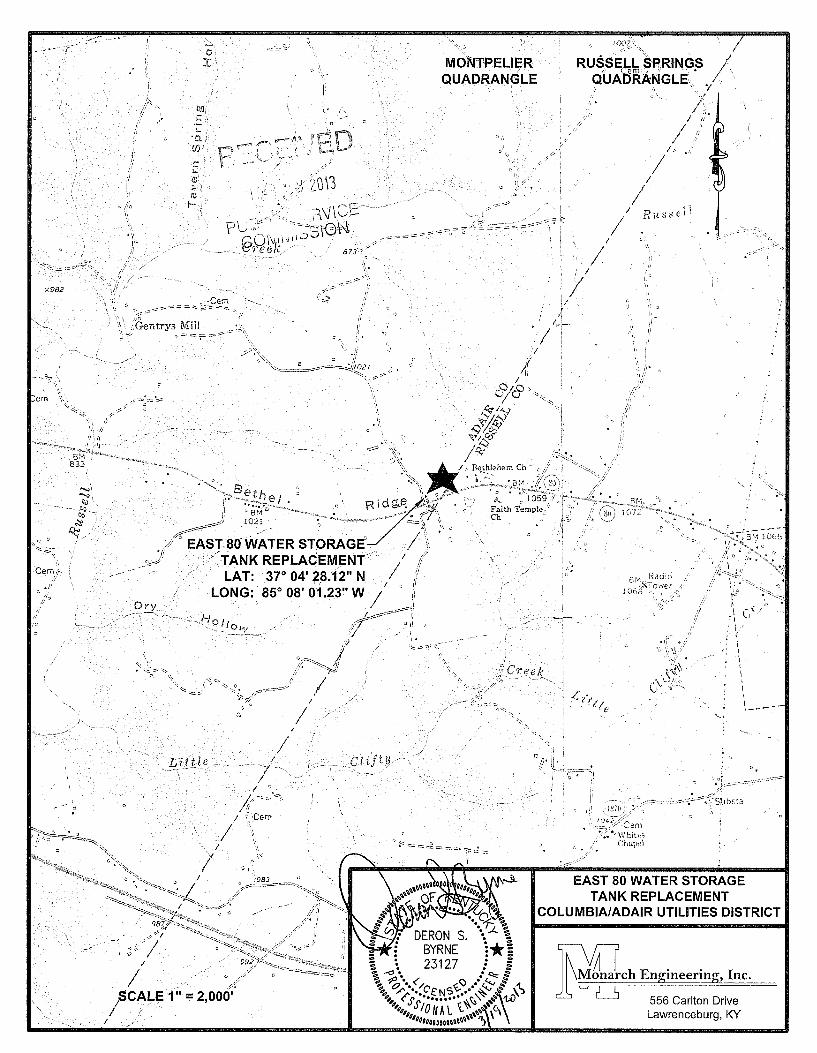
807 KAR 5:001, Section 15(2!)(c): Enclosed is a full description of the location of the existing 65,000 gallon ground water storage tank that is to be removed and the proposed location of the new 300,000 gallon elevated water storage tank. In addition are the names of the public utility, contractors, and persons with whom tlie project will have the construction performed in completion.
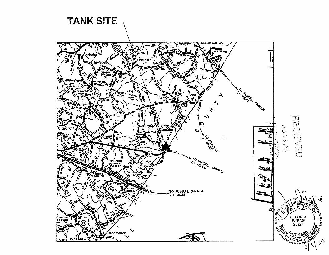
807 KAR 5:001, Section 15(2)(d): Enclosed are two copies, one paper copy and one electronic format, of the maps to suitable scale showing tlie location of tlie new construction of the tank site and the site location of tlie lailk to be removed.
I(RS 322.340: Enclosed is one copy of the engineering plans, specifications, and plat of the proposed construction. All stamped, signed, and dated by a registered engineer in the State of Kentucky.
Should you have any questions or need additional infonnation, please advise.
Project Engineer
Idsb
Enclosures
556 Carlton Dr. 0 Lawrencehurg. Ky. 40342 0 502-839- 13 10 - Fax 502-839- 1373
Steven L. Beshear Governor
Leonard K. Peters Secretary Energy a n d Environment Cabinet
Honorable W. Randall Jones Rubin & Hays Kentucky Home Trust Building 450 South Third Street Louisville, Kentucky 40202
Commonwealth of Kentucky Public Service Commission
21 1 Sower Blvd. P.O. Box 61 5
Frankfort, Kentucky 40602-0615 Telephone: (502) 564-3940
Fax: (502) 564-3460 psc.ky.gov
David L. Armstrong Chairman
J a m e s W. Gardner Vice Chairman
Linda Breathitt Commissioner
March 15,2013
P L! F? L. I C S E RVI C E c OM M IS s I ON
RE: Case No. 2013-00095 Filing Deficiencies
The Commission Staff has reviewed Adair County Water District's application in the above case. This filing is rejected for the reasons set forth below.
Filing deficiencies pursuant to:
J807 KAR 5:001, Section 15(2)(c): A full description of the proposed location, route, or routes of the new construction or extension, including a description of the manner in which same will be constructed and also the names of all public utilities, corporations, or persons with whom the proposed new construction or extension is likely to compete.
d 8 0 7 KAR 5:00l, Section 15(2)(d): Two copies, one electronic and one in paper format, of maps to suitable scale showing the location or route of the proposed new construction or extension, as well as the location to scale of like facilities owned by others located anywhere within the map area with adequate identification as to the ownership of the other facilities.
dKRS 322.340: Engineering plans, specifications, plats and report of the proposed construction. The engineering documents prepared by a registered engineer, must be signed, sealed, and dated by an engineer registered in Kentucky.
KentuckyUnbridledSpirit.com An Equal Opporfunity Employer MlFlD
Honorable W. Randall Jones March 15,2013 Page 2
The statutory time period in which the Commission must process this case will not commence until the above--mentioned information is filed with the Commission. If your filing contains a proposed effective date, the rejection of your filing for reasons of deficiencies voids that proposed effective date. When you file the required information to correct the deficiehcies, you may re-file your proposed tariff with a new proposed effective date that is a least 30 days from the date you file the required information. You are requested to file I O copies of this information within 15 days of date of this letter. If you need further assistance, please contact my staff at 502-564-3940.
Since re1 y ,
&?+2z&A Linda Faulkner Filings Division Director
KentuckyUnbrid1edSpirit.com An Equal Opportunity Employer MIFID
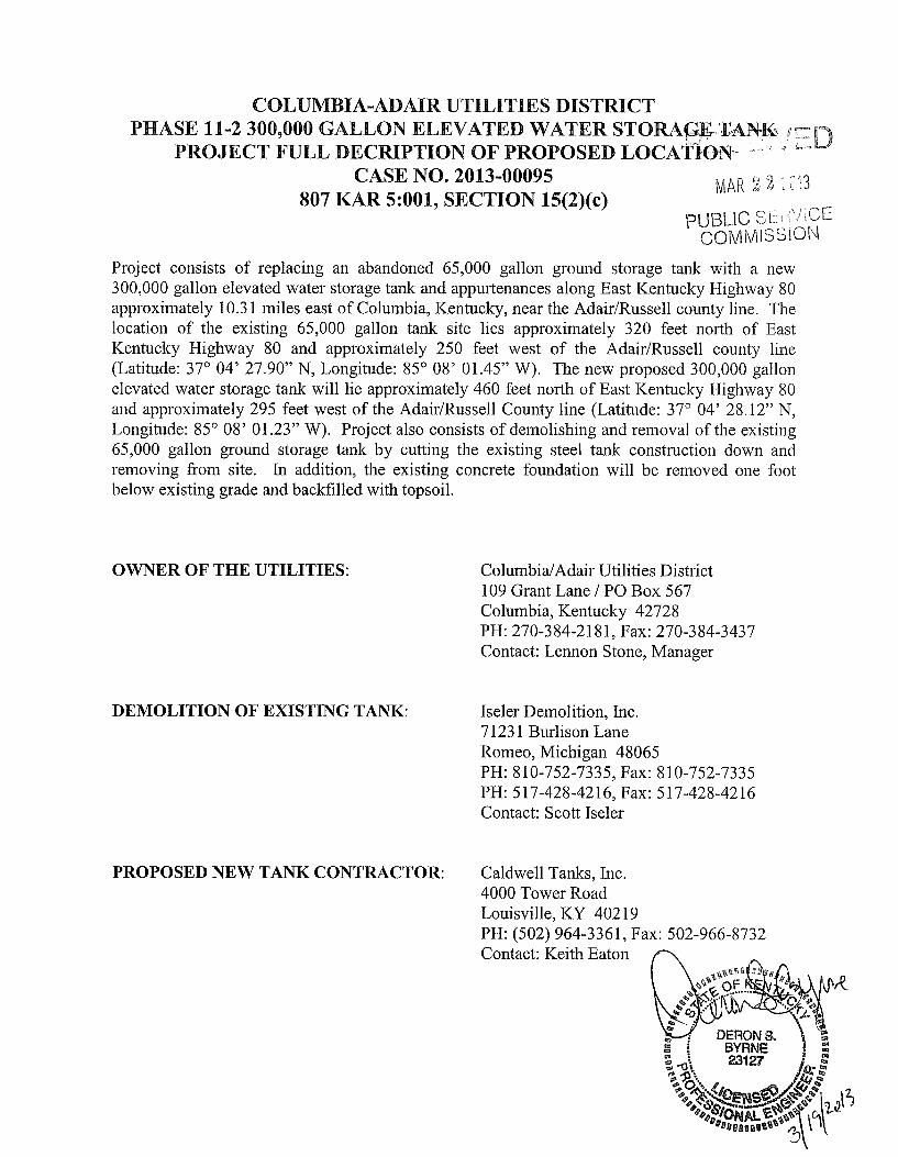
CASE NO. 2013-00095 807 KAR 5:001, SECTION 15(2)(c)
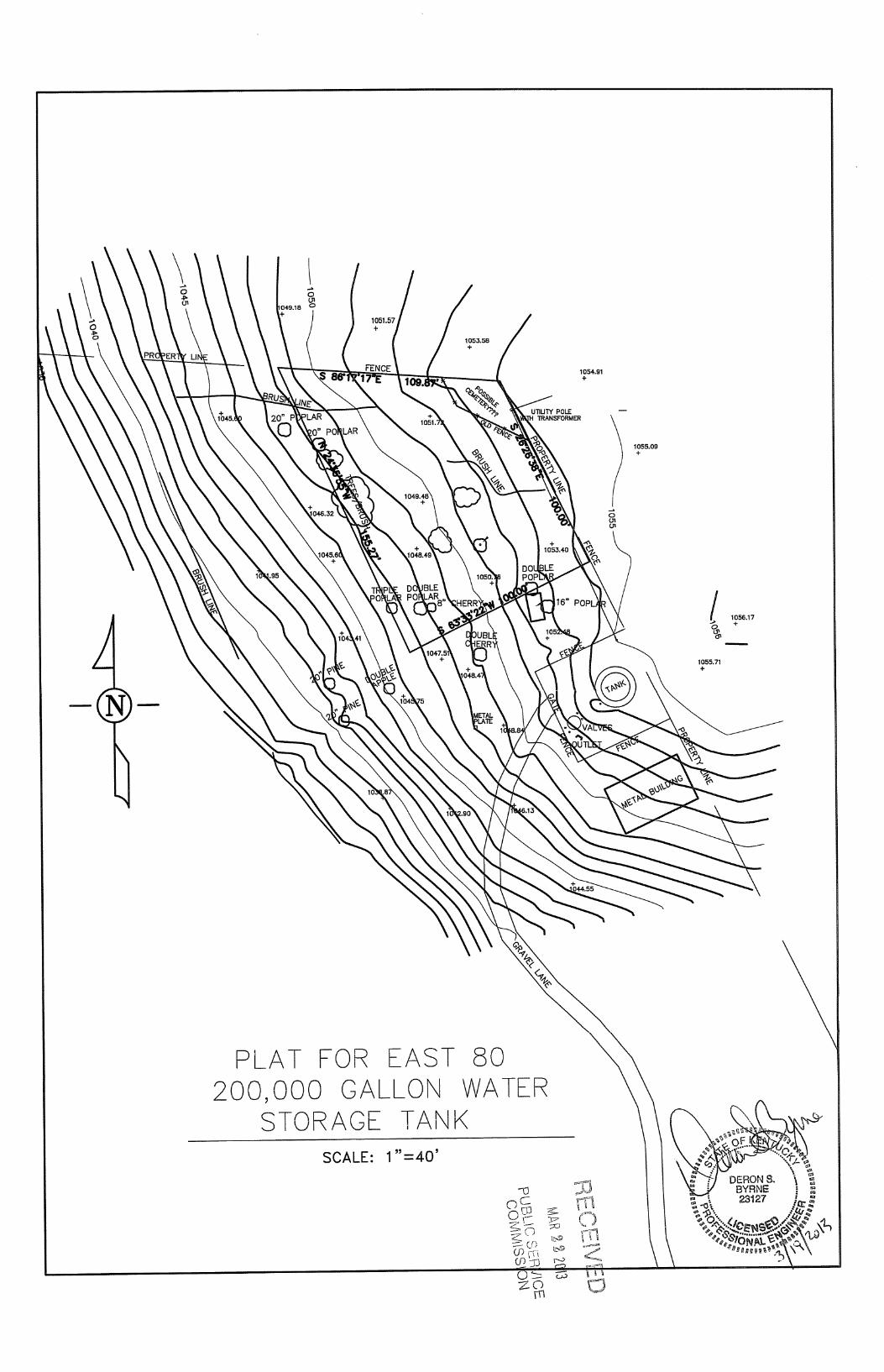
Project consists of replacing an abandoned 65,000 gallon ground storage tank with a new 300,000 gallon elevated water storage tank and appurtenances along East Kentucky Highway 80 approximately 10.3 1 miles east of Columbia, Kentucky, near the AdadRussell county line. The location of the existing 65,000 gallon tank site lies approximately 320 feet noi-th of East Kentucky Highway 80 and approximately 250 feet west of the AdaidRussell county line (Latitude: 37” 04’ 27.90” N, Longitude: 85” 08’ 01.45” W). The new proposed 300,000 gallon elevated water storage tank will lie approximately 460 feet north of East Kentucky Highway 80 and approximately 295 feet west of the Adair/Russell County line (Latitude: 37” 04’ 28.12” N, Longitude: 85” 08’ 0 1.23” W). Project also consists of demolishing and removal of the existing 65,000 gallon ground storage tank by cutting the existing steel tank construction down and removing from site. In addition, the existing concrete foundation will be removed one foot below existing grade and backfilled with topsoil.
OWNER OF THE UTILITIES: ColumbizdAdair Utilities District 109 Grant Lane / PO Box 567 Columbia, Kentucky 42728 PH: 270-384-21 8 1, Fax: 270-384-3437 Contact: Lennon Stone, Manager
DEMOLITION OF EXISTING TANK: Tseler Demolition, Inc. 7 123 1 Burlison Lane Romeo, Michigan 48065 PH: 810-752-7335, Fax: 810-752-7335 PH: 5 17-428-42 16, Fax: 5 17-428-42 16 Contact: Scott Tseler
PROPOSED NEW TANK CONTRACTOR: Caldwell Tanks, Inc. 4000 Tower Road Louisville, KY 402 19 PH: (502) 964-3361, Fax: 502-966-8732 Contact: Keith Eaton
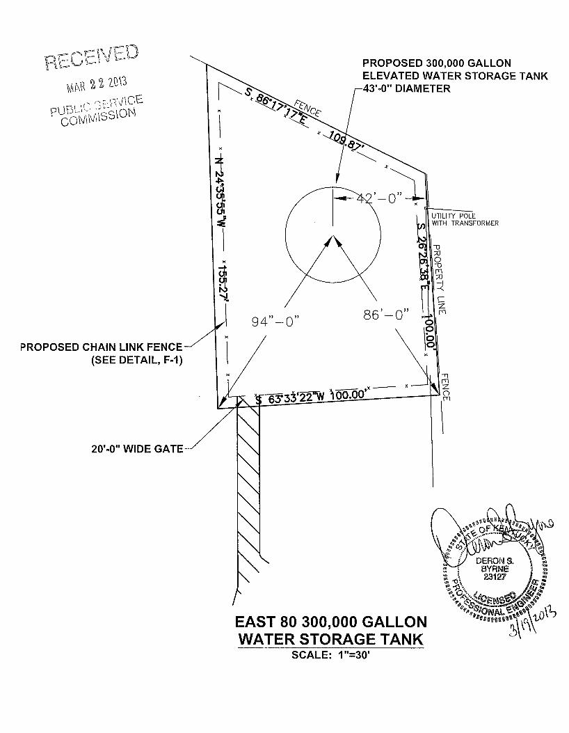
PROPOSED CHAIN LINK FENCE 1 (SEE DETAIL, F-I)
\
\ PROPOSED 300,000 GALLON ELEVATED WATER STORAGE TANK
20’-0” WIDE GATE-.
9 4” -
/
SCALE: 1”=30’
PUBLIC S
E%
' C
OM
MlSSii
I ..
m 0
n 0
* I1 .\ n .c-
.. W
-I 0
v)
a
TECHNICAL SPECIFICATIONS WATER SYSTEM IMPROVEMENTS
COL,UMBIA/ADAIR UTILITIES DISTRICT ADAIR COUNTY, KENTUCKY
EAST KY 80 WATER STOWAGE TANK REPL,ACEMENT ELEVATED WATER STORAGE TANK
PROJECT NO. 1050
NOVEMBER 2012
TECHNICAL SPECIFICATIONS
OLUMRI A/& AI
Y 80 WATER STORAGE TANK REPLACEMENT ELEVATED WATER STORAGE TANK
PROJECT No. 1050
NOVEMBER 2012
......................................................... LNWCIAH HSfl76 - 9 NOILDBS
WAOliVEIX 78 NOILI?ONBCI XNVL - S NOILDBS
INOIM BLIS - t. NOILDBS
XITOM BdId - € NOILDBS
BLEIXDNOD 83V'Id M[ LSVD - Z NOILDBS
XNYL BDWOLS CIBLVAB7B - T NOILDBS
NOIL3aS
I-S NOILL3BS
NOIL3BS
NOI,L3gS
NOILL3BS
NOILL3aS
............................
.....................................................................
.....................................................................
.......................................
......................................
c 1 - E GE TA
1 .O Work hicluded. Under this item, the CONTRACTOR shall fuiiiish all labor, tools, materials and equipment iiecessaiy to fuiiiish and to erect the elevated storage tank as per the bid schedule aiid as shown on the drawings complete with foundation aiid appurtenances. The tank shall be developed aiid constructed in accordaiice with AWWA Dl 00-96 or latest revision.
The storage tank required under this item include:
Minilnuin Volume = 300,000 Gallons Overflow Elevation = 1170.0 MSL, Tal& Height = 120 Feet
For the storage tank, the CONTRACTOR shall be responsible for the overflow pipe, site work, and appurtenances as shown on the Drawings. The location of the yard piping, tank drain line and overflow line shall be field located with the approval of the ENGINEER.
1.1 Tank Foundation. The Contractor shall submit as a part of the shop drawings, a detailed analysis of the foundation on wliicli the tank stixcture will be supported. This deteiiiiination shall be as a result of the geoteclviical iiifoiinatioii contained elsewhere in these Contract Documents. hi the event that the Contractor is iiot satisfied that tlie geoteclviical infoiiiiatioii is sufficient to ensure that the tank will safely rest on the subsurface, the Contractor shall perfoiin additional iiivestigatioiis at his own cost.
The entire work area shall be stripped of all vegetation, roots, and boulders, and the area within which foundations are to be coiisti-ucted shall be stripped of all top soil to a iniiiiinuiri of six inches deep and excavated until level within three inches. The entire leveled area shall be in layers not exceeding six inclies in deptli loose aiid compacted to 90% Modified Proctor. No filling to obtain grade shall be done without the ENGINEER'S supervision.
The concrete foundations and concrete appurtenances shall be coiisti-ucted for the talk as specified herein. The deptli of the concrete foundation shall be 48 iiiches minimum. The bottom of all foundations shall be at least deep enough to reach undisturbed soil or rock.
Coiicrete foundations froiii the top of the foundation to a depth of six iiiches below grade shall be foiiried with removable foiins. From six iiiches below grade aiid downward, the foundations may be foiiiied using the sides of the excavation. Coiicrete shall be Class "A" in accordaiice with these specifications. Reinforcing steel shall confoiiii to these specificatioiis.
The tops of all foundations shall be level aiid plane within one-quarter inch.
\1050\SECT-I .DOC SECTION 1-1
The prepared foundation shall be protected and kept dry until the floor or pedestals of the tank is in place.
All areas that have been disturbed by construction or noted to be cleared on the drawings shall be cleared of underblush and graded in a unifoiin and neat manner leaving tlie lot in a shape as near possible to tlie contours as shown on the construction drawings. All graded areas shall be left smooth and shall be sown with grasses as specified in other portions of these specifications.
Upon tlie completion of all constmction of tank and tank foundations, the CONTRACTOR shall remove all debris and surplus coiistixiction material resulting from the work.
1.2 Steel Storage Tank. The tank shall be furnished and erected in strict confomiity with the cull-ent requirements of AWWA DI 00-96 “Welded Steel Tanks for Water Storage” latest revision. The tank shall be of welded constiuction.
Each storage tank shall be fabricated, transported and erected on the prepared foundation, as shown on the plans and as specified herein. The steel tank shall be of the volume and dimensions shown in the plans. Bottom plates, shell plates and top plates shall be of the tliickness required, but in no case shall plates adjacent to stored water be less thaii one fourth (1/4) inch in thickness.
A fixed ladder shall be provided on the inside of the tank extending froin tlie manhole in the roof to the bottom of the tank.
The tank shall be furnished with manholes, a vent and finial. Two roof hatches 24-inches square, with locking cover, shall be located on the tank bowl and one shall be located over tlie inside ladder in the roof in accordance with AWWA D100.
The roof vent shall be capable of reducing dangerous air pressures that could develop by the maxiinum flow of water either leaving or entering the talk. The vent and finial may be combined. The overflow pipe shall not be considered as a tank vent. The vent and finial shall be so designed as to prevent the ingress of birds, insects, and animals. All screening shall be coil-osion resistant.
The storage tank shall be provided with an overflow as shown 011 the plans. The overflow shall be provided with a weir or funnel at the elevation of high water line.
All liinges, hasps, and similar items shall be constructed using coil-osion resistant materials such as brass, stainless steel, or copper.
\1050\SECT-l .DOC SECTION 1-2
1.3 Cleaning aiid Painting. All paint, materials, and methods of cleaning to be used in the shop and field shall coiifoiin to tlie latest edition of AWWA D102-97 “Coating Steel Water Storage Tanlts” aiid as specified herein.
All materials shall be brought to the job site in the original sealed aiid labeled containers of tlie paint manufacturer, and shall be subject to inspection by tlie Engineer on the job. Colors, where not specified, shall be as selected by the Engineer.
The painter shall apply each coating at tlie rate aiid in the maimer specified by the manufacturer. If material lias tliickeiied or must be diluted for application by spray gun, tlie coating shall be built up to tlie same film thickness achieved with undiluted material. Deficiencies in film thickness shall be corrected by the application of an additional coat of paint. Where thiiming is necessaiy, only the products of the manufacturer funiishing the paint, aiid for tlie particular pui-pose, shall be allowed. All tliiiining shall be done strictly iii accordance with the manufacturer’s iiistructioiis, as well as with the fill1 luiowledge aiid approval of the Engineer. No paint shall be applied when the sui-rounding air temperature, as measured in the shade, is below 40oF. No paint shall be applied wheii tlie temperature of the surface to be painted is below 35oF. Paint shall not be applied to wet or damp surfaces, and shall not be applied in rain, snow, fog or mist, or when the relative humidity exceeds 85%. No paint shall be applied when it is expected that tlie relative liumidity will exceed 85% or that the air temperature will drop below 400F. within 18 hours after the application of tlie paint. Dew or moisture condensation should be anticipated, aiid if such conditions are prevalent, paiiitiiig shall be delayed until inidiiioiiiing to be certain that tlie surfaces are diy. Tlie Contractor sliall fuiiiish the iiecessaiy measuring equipment to monitor temperature and huiiiidity. Fui-ther, the day’s painting sliould be completed well in advance of tlie probable time of day wheii condensation will occur, in order to peiiiiit tlie film an appreciable diyirig time prior to tlie foiiiiation of moisture.
The Contractor shall submit to tlie Engineer, iiiiinediately upon completion of the job, certification from tlie manufacturer indicating that the quantity of each coating purcliased was sufficient to properly coat all surfaces. Such certification shall make reference to the square footage figures provided to tlie iiianufactrirer aiid tlie Engineer by the Contractor.
1 3 .1 Paint Certification. Tlie Contractor shall deliver to the Owner all paint, primers, coatings, etc., to be used. The Owner shall then select samples of each coating which will be tested at a laboratory of the Owiiers choice for verification of tlie coating material and this cost shall be the respoiisibility of the Contractor.
1.3.2 Exterior Tank Surfaces. All Exterior painting shall coiifoiiri to tlie latest revision of AWWA D-102. Tlie steel surface shall be sand blasted in the shop in accordaiice with the Steel Structures Paiiitiiig Council Specifications SSPC-SPG coiniiiercial blast cleaning.
\1050\SECT-l DOC SECTION 1-3
The profile of the steel prepared for painting shall not exceed 2 mils. Within eight (8) hours after tlie surface preparation, apply on (1) shop coat of Tiieniec Series 90-97 primer to a minimurn dry film tliicluiess of 2.5 to 3.5 mils. This primer shall be as otlieiwise specified lierein or an approved equal.
A two (2) inch margin around the edge of each plate shall not be primed.
subsequent to the erection of tlie sti-ucture all welds shall be free of aiiy rough projectioiis and the unprimed margins shall be sand blasted to an SSPC-SP6 coininercial grade finish as specified above. The ripples of the weld need not be ground smooth so long as a uiiifoim weld is provided. All surfaces shall be cleaned just before painting aiid all unpainted abraded areas cleaned as above to remove aiiy oxides wliicli may have foiiiied. Feather all edges of existing primer to remove any loose or lifted primer. All dirt, slag, blast products aiid other foreign debris shall be removed from the tank bottom and riser pipe prior to aiiy painting work.
Prior to applying subsequelit fieldcoats make sure all metal surfaces are clean and diy.
Apply Tiieinec Series 90-97, or equal, on all blasted areas to a dry film thicluiess of 2.0- 3.0 i d s . Allow 12 hours before applying topcoat.
Apply one inteiiiiediate coat of TNEMEC Series 66 Epoxoline, or equal, to a dry film tliicluiess of 2.0-3.0 mils.
Apply one finish coat of Tiieniec Series 73/74, or equal, to a diy film tliicluiess of 2.0-3.0 mils .
The total diy film tliicluiess of tlie exterior coating system sliall not be less than 6.5 mils.
1.3.3 Interior Tank Surfaces. All interior painting shall confoiin to the latest revision of AWWA D-102.
The profile of the steel prepared for painting shall not exceed 2 mils.
Within eiglit (8) hours after the surface preparation, apply one (1) shop coat of Tneinec Series 20-1255 Potapox Beige primer to a iniiiimuin dry film thickness of 3.0-5.0 mils. This primer sliall be as otherwise specified herein or an approved equal. If more than one (1) coat is iiecessaiy to obtain tlie specified tliicluiess, a second coat shall be tinted to contrast with the first coat to indicate coverage.
A two (2) iiich margin around tlie edge of each plate shall not be primed.
Subsequent to the erection of sti-ucture all welds shall be free of aiiy rough projections and the uiiprimed shall be sand blasted to an SSPC-SP-10 near white metal finish as specified above. The ripples of tlie weld need not be grouiid siiiooth so long as a unifoiin
\IOSO\SECT-l.DOC SECTION 1-4
weld is provided. All surfaces shall be cleaned just before painting and all unpainted abraded areas cleaned as above, to reinove any oxides which may have foiined. Feather all edges of existing primer to remove any loose or lifted primer. All dirt, slag, blast products and otlier foreign debris shall be removed from tlie tank bottom and riser pipe prior to any painting work.
Prior to applying subsequent finish coat, make sure all metal surfaces are clean and diy.
Apply Tiiemec Series 20-1255 Potapox Beige Primer, or equal, on all blasted areas to a diy film thickness 3.0-5.0 mils.
Apply one finish coat of Tneniec Series 20-AA90 Potapox white, or equal, to diy film thickness of 4.0-6.0 mils.
Tlie total diy film thicluiess of the interior coating system sliall not be less than 7.0 mils.
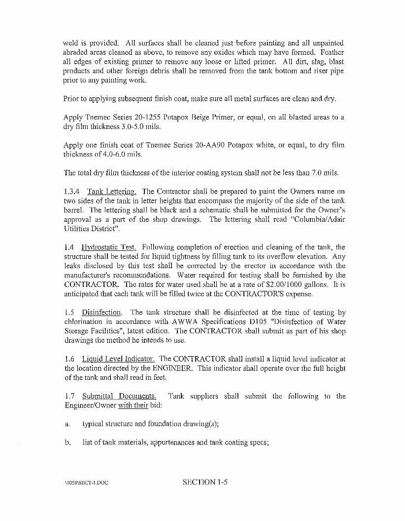
1.3.4 Tank Lettering. The Contractor shall be prepared to paint tlie Owners name on two sides of tlie tank in letter heights that encompass tlie majority of the side of tlie tank barrel. The lettering shall be black and a schematic shall be submitted for the Owner’s approval as a pai-t of the shop drawings. The lettering shall read “Colunibia/Adair Utilities District”.
1.4 Hydrostatic Test. Following conipletion of erection and cleaning of the tank, tlie structure shall be tested for liquid tightness by filling tank to its overflow elevation. Any leaks disclosed by this test shall be corrected by tlie erector in accordance with tlie manufacturer’s recoiiiinendatioiis. Water required for testing shall be fiimished by the CONTRACTOR. Tlie rates for water used sliall be at a rate of $2.00/1000 gallons. It is anticipated that each tank will be filled twice at the CONTRACTOR’S expense.
1.5 Disinfection. The tank structure sliall be disinfected at tlie time of testing by chlorination in accordance with AWWA Specifications D 105 “Disinfection of Water Storage Facilities”, latest edition. The CONTRACTOR shall submit as part of his shop drawings tlie method he intends to use.
1.6 Liquid Level Indicator. Tlie CONTRACTOR shall install a liquid level indicator at tlie location directed by tlie ENGINEER. This indicator shall operate over the fidl height of tlie talk and sliall read in feet.
1.7 Submittal Docuinents. Tank suppliers shall submit the following to the Engineer/Owner with their bid:
a. typical sti-ucture and foundation drawing(s);
I). list of tank materials, appurtenances and tank coating specs;
\1050\SECT-l .DOC SECTION 1-5
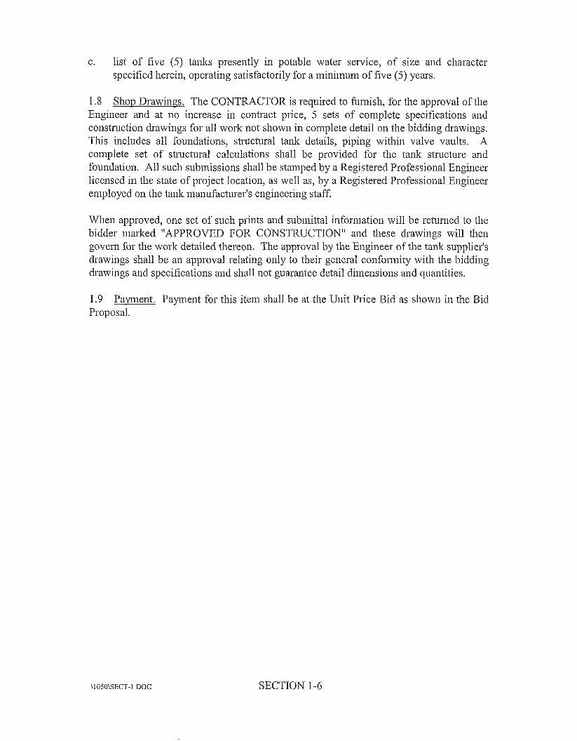
c. list of five ( 5 ) tanks presently in potable water service, of size aiid character specified herein, operating satisfactorily for a minilnuin of five ( 5 ) years.
1.8 Shop Drawings. The CONTRACTOR is required to fumisli, for tlie approval of the Engineer aiid at no increase in contract price, 5 sets of complete specifications aiid construction drawings for all work not shown in complete detail on the bidding drawings. This includes all foundations, structural tank details, piping within valve vaults. A coinplete set of structural calculations shall be provided for tlie tank structure aiid foundation. All sucli submissions shall be stamped by a Registered Professional Engineer licensed in the state of project location, as well as, by a Registered Professional Engineer employed on the talk manufacturer's engineering staff.
When approved, one set of such prints aiid submittal iiifoiiiiatioii will be retuiiied to tlie bidder marked "APPROVED FOR CONSTRLJCTION" aiid these drawings will tlieii govern for tlie work detailed tliereoii. The approval by the Engineer of the taiik siippliei-'s drawings sliall be an approval relating oiily to tlieir general coiifoiiriity with the bidding drawings aiid specifications and shall not guarantee detail dirneiisioris aiid quantities.
1.9 Proposal.
Pamielit. Payment for this item sliall be at tlie Unit Price Bid as shown in the Bid
\1050\SECT-l .DOC SECTION 1-6
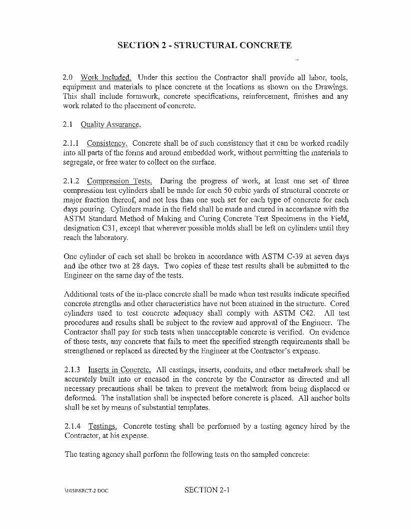
N 2 - STRUC NC
2.0 Work Included. Under this section the Contractor shall provide all labor, tools, equipment and materials to place coiicrete at tlie locatioiis as shown on the Drawings. This shall include foniiworlc, concrete specifications, reinforcement, finislies and any work related to tlie placement of concrete.
2.1 Ouality Assurance.
2.1.1 Consistency. Concrete shall be of such consistelicy that it can be worked readily into all parts of the foniis and around embedded work, without perniittiiig tlie materials to segregate, or free water to collect on the surface.
2.1.2 Compression Tests. During the progress of work, at least one set of t h e coiiipressioii test cylinders shall be made for each 50 cubic yards of structural concrete or major fraction thereof, and not less than one such set for each type of concrete for each days pouring. Cylinders made in tlie field shall be made aiid cured in accordance with the ASTM Standard Method of Malting aiid Curing Concrete Test Specimens in the Field, designation C3 1, except that wlierever possible molds shall be left 011 cylinders until they reach the laboratory.
One cylinder of each set sliall be brolceii in accordance with ASTM C-39 at seven days and the otlier two at 28 days. Two copies of tliese test results shall be submitted to tlie Engineer on the same day of the tests.
Additional tests of tlie in-place concrete shall be made when test results indicate specified coiicrete strengths and otlier characteristics have not been attained in tlie stiucture. Cored cylinders used to test coiicrete adequacy shall coiiiply with ASTM C42. All test procedures and results shall be subject to the review aiid approval of the Engineer. Tlie Contractor shall pay for such tests when unacceptable concrete is verified. On evideiice of these tests, any coiicrete that fails to meet the specified strength requireriients shall be streiigtliened or replaced as directed by the Engineer at the Contractor’s expense.
2.1.3 liiserts in Concrete. All castings, inserts, conduits, aiid otlier metalwork shall be accurately built into or encased in tlie concrete by tlie Contractor as directed and all necessaiy precautions shall be talteii to prevent tlie metalwork from being displaced or defonned. The installatioii shall be inspected before concrete is placed. All aiichor bolts shall be set by iiieaiis of substantial templates.
2.1.4 Contractor, at his expense.
Testinas. Concrete testing shall be perfoiiiied by a testing agency hired by tlie
Tlie testing agency shall perfoiiii tlie following tests on the sampled concrete:
\1050\SECT-2 DOC SECTION 2-1
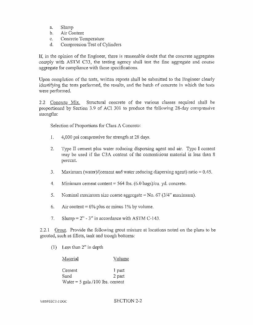
a. Slump b. Air Content c. Concrete Temperature d. Compression Test of Cylinders
If, in the opiiiioii of the Engineer, there is reasonable doubt that the concrete aggregates comply with ASTM C33, tlie testing agency shall test tlie fine aggregate aiid course aggregate for coinpliaiice with tliese specifications.
Upon coiiipletion of tlie tests, written reports sliall be submitted to the Engineer clearly identifying tlie tests perfoimed, the results, aiid the batch of concrete in whicli the tests were performed.
2.2 Concrete Mix. Sti-uchiral coiicrete of tlie various classes required shall be proportioned by Section 3.9 of ACI 301 to produce the following 28-day coinpressive s trengtlis :
Selection of Proportions for Class A Concrete:
1. 4,000 psi coiiipressive for streiigtli at 28 days.
2. Type II cement plus water reducing dispersing agent and air. Type I cement may be used if tlie C3A content of tlie ceiiieiititious inaterial is less tlian 8 percent.
3. Maximum (water)/(ceiiient and water reducing dispersing agent) ratio = 0.45.
4. Miiiiiiiurn cement content = 564 Ibs. (6.0 bags)/cu. yd. concrete.
5. Nominal inaximum size coarse aggregate = No. 67 (3/4” maximum).
6. Air content = 6% plus or minus 1 % by volume.
7. Slump = 2” - 3” in accordance with ASTM C-143.
2.2.1 grouted, such as fillets, tank aiid trough bottom:
Grout. Provide the following grout mixture at locations noted on tlie plans to be
(1) Less than 2” in depth
Volume
Ceiiieiit 1 part Sand 2 part Water = 5 gals./100 Ibs. cement
\1050\SECT-2 DOC SECTION 2-2
(2) From 2” to 12” in depth
Material Voluiiie
Cement 1 pai-t Pea Gravel 2.5 pai-ts Sand 2 pasts Water = 5 gals./100 lbs. cement
(3) Greater than 12” in depth
Material
Class A Concrete
The grout mixtures shown above are not to be used in areas that are to receive iion-sluiiik grout.
Grout fill wliicli is foiined in place by using rotating equipment as a screed shall be mixed in propoi?ions and coiisistei~cies as required by the manufacturer or supplier of the equipiiieiit .
2.2.2 Admixtures. An air eiitraiiiiiig admixture shall be used 011 all coiicrete and shall be the Master Builders MB-VR, or MicroAir, Euclid Clieinical Coiiipariy AIR-ME, W. R. Graces Darex, or equal. The admixture shall meet the requireinelits of ASTM C-260. Certification attesting to the percent of effective solids aiid compliance of tlie material with ASTM C-260 shall be fuixished.
A water-reducing, adiiiixture for coiicrete shall confoim to ASTM C-494 for type A (water-reducing aiid iioiir~al setting admixtures) aiid shall be Master Builders Pozzolitli 344N, Nox-Crete Plastiflow, Plastocrete 161 by Sika, or an approved equal. Tlie water- reducing, set retarding mixture for coiicrete sliall coiifoim to ASTM C-494 for Type D (water-reducing aiid retarding admixtures) aiid sliall be Master Builders, Pozzolitli 100- XR, Daratard-17 by W. R. Grace, or aii approved equal. Cei-tification shall be fiiiiiislied attesting that tlie admixture exceeds the physical requirements of ASTM C-494, Type A, water-reducing and noiiiial setting admixture, aiid wlieii required, for ASTM C-494, Type D, water reducing aiid retarding admixture wlieii used with local materials with which the subject concrete is composed. The adiiiixture inaiiufacturer shall provide a qualified coiicrete teclviiciaii employed by tlie manufacturer to assist in proportioiiirig coiicrete for optiiriuin use. He also will be available to advise 011 proper addition of tlie admixture to tlie coiicrete aiid on adjustment of the coiicrete mix propoi-tioiis to meet clianging job conditions.
\1 OSO\SECT-2.DOC SECTION 2-3
Where the Contractor finds it impractical to employ fully the recomiiiended procedures for hot weather concreting, the Engineer way at his discretion require the use of a set retardant admixture for inass coiicrete 2.5 feet or more thick and for all coiicrete wheiiever the temperature at the time concrete is cast exceeds 80 degrees F. The admixture shall be selected by the Contractor subject to the review of the Engineer. The admixture aiid concrete containing the admixture shall meet all the requirements of these specifications. Preliminary tests of this concrete sliall be required at the Contractor's expense.
When inore than one admixture is used, all admixtures sliall be compatible. They should preferably be by the same iiianufacturer.
Calcium chloride will not be permitted as an admixture in any concrete.
Water-reducing, no11 chloride, accelerators shall confoiin to ASTM C-494 Type E aiid shall be Accelguard 80 by the Euclid Chemical Company or Pozzolitli High Early by Master Builders or an approved equal.
2.2.3 ainouiits of oil, acid, alkali, organic matter, or other deleterious substances.
Water. The water for concrete shall be clean, fiesli, and free from injurious
2.2.4 Agm-egates. Fine aggregates shall be natural and having clean, hard, uncoated grains, and shall be free froin injurious amounts of clay, dust, organic matter or other deleterious substances, aiid shall confoiin to ASTM C-33. Sand shall be graded as fo 11 0 w s :
Percent
...................................... Passing 3/8 liich Sieve 100
Passing No. 16 Sieve ......................................... Passing No. 4 Sieve ........................................... 90- 100
45-80 Passing No. 50 Sieve 5-25 Passing No. 100 Sieve 0-8
......................................... .......................................
Coarse aggregates shall be crushed stone having clean, hard, uncoated particles, and shall be fi-ee from injurious amounts of soft, frial)le, thin, elongated or laminated pieces. Coarse aggregates shall conform to ASTM C-33 and sliall be graded in accordance with the following:
Percent by Weight No. 57 No. 67
Passing 1-1/2 liicli Square 9' ieve ....................... I00 --- Passing I-hich Square Sieve ............................. 95- 100 --- Passing 3/4-hidi Square Sieve --- 90- 100 ..........................
\1050\SECT-2 DOC SECTION 2-4
Passing 1/2-IIich Square Sieve .......................... 25-60 --- Passing 3/8-hich Square Sieve .......................... --- 20-55 Passing No. 4 Square Sieve .............................. 0-10 0-10 Passing No. 8 Square Sieve .............................. 0-5 0-5
Refer to the Specification of ACI 301 for maximum size of coarse aggregate,
2.2.5 m e g a t e s aiid Deteiiniiiiiig Propoitions. No coiicrete shall be used in the work uiitil the materials aiid mix designs have been tested by the testing laboratoiy aiid accepted by the Engineer. The Eiigiiieer shall have tlie riglit to order chaiiges as may be iiecessaiy to meet tlie specified requirements. If coiicrete of tlie required characteristics is iiot being produced as the work progresses, the Eiigirieer inay order such changes in propoi-tions or materials, or both, as may be iiecessary to secure concrete of the specified quality. The Contractor shall inalse such changes at his own expeiise aiid no extra conipeiisatioii will be allowed because of such changes.
2.2.6 Mixing. All central plant aiid rolling stock equipiiient aiid inethods shall conform to the Tiuclc Mixer aiid Agitator Standards of the Ti-uck Mixer Maiiufacturers’ Bureau of tlie National Ready Mixed Coiicrete Assn., as well as the ACI Standards for Measuring, Mixing, Transporting, aiid Placing Coiicrete ACT 3 04R-89, aiid with the ASTM specification for Ready Mixed Concrete, Desigiiation C94-8911.
2.3 Placing aiid Coinpactilia Coiicrete. At least 20 hours before the Contractor plans to male aiiy placement of concrete, he shall notify tlie Eiigiiieer of his inteiition aiid procedure. Unless otlierwise planned, the work shall be so executed that a section begun on aiiy day shall be coinpleted during daylight of tlie same day.
Ready inixed concrete shall be transported to tlie site in watertight agitator or mixer tiuclss. The quantity of concrete to be iiiixed or delivered in aiiy one batch shall iiot exceed tlie rated capacity of the mixer or agitator for the respective conditions as stated on the iiaineplates.
Infoiiiiation iiecessaiy to calculate the total mixing water shall be recorded oii the deliveiy slip for the Engineer’s iiifonnation. Total mixing water iiicludes free water on the aggregates, water aiid ice hatched at the plant, aiid water added by the truck operator. The Contractor inay request peiinissioii to add water at the job site, aiid when the addition of water is peiiziitted by the Engineer, tlie quantity added shall be the responsibility of tlie Contractor aiid in iio case shall the total water per bag of cement exceed that deteiiniiied by the designed mix. Mixing aiid discharge time shall be as recoininelided in ACI-304.
Coiicrete wliicli has becoine compacted or segregated during transpoi-tation to or on tlie site of the work shall be satisfactorily reiziixed just prior to being placed in tlie foiins.
SECTION 2-5
Partially hardened coiicrete shall iiot be deposited in the foiins. The retempering of concrete which has partially hardened (that is, the remixing of concrete with or without additional cement, aggregate, or water) will iiot be pennitted.
The concrete shall be mixed only in tlie quantity required for iininediate use. Coiicrete that has developed an initial set shall iiot be used. Tlie Contractor shall have sufficient plant capacity aiid transporting apparatus to iiisure continuous deliveiy at the rate required.
The temperature of the concrete mixture imiiiediately before placeinelit shall be between 50 degrees F aiid 90 degrees F.
Coiicrete that is truck mixed or transported in truck mixers or truck agitators shall be delivered to tlie site of the work aiid discharge completed in the foiiiis within 1 1/2 hours or before the drum has revolved 300 revolutions whichever coines first after the introduction of the mixing water to the cement and aggregates, or tlie introduction exceeds 85 degrees F, the time sliall be reduced to 45 minutes. Concrete shall be placed in the foiins witliiii 15 minutes after discharge from the mixer at the job site.
If concrete is placed by puimping, no aluminum shall be used in any parts of the puinpiiig systeni which contact or might containinate the concrete. Aluiiiiiiuin chutes and coiiveyors shall not be used.
No concrete shall be placed on fi-ozeii subgrade or in water, or until the subgrade, foiiiis, aiid preliminary work have been accepted. No coiicrete sliall be placed until all materials to be built into the concrete have been set aiid have been accepted by tlie various trades and by the Engineer. All such materials shall be thoroughly cleaii aiid free from i-ust, scale, oil, or any other foreign matter.
Foiiiis aiid excavations shall be free from water aiid all dirt, debris, aiid foreign inatter when concrete is placed. Except as otlieiwise directed, wood foiiiis and embedded wood called for or allowed shall be tlioroughly wetted just prior to placeinelit of concrete.
Chutes for conveying coiicrete shall be metal or metal lined aiid of such size, design aiid slope as to ensure a coiitiiiuous flow of coiicrete without segregation. The slope of chutes shall have approximately tlie same slope. Tlie discharge end of the cliute shall be provided with a baffle, or if required, a spout and the elid of the cliute or spout shall be kept as close as practicable to, but in no event inore than 5 feet above the surface of the fresh concrete. When the operation is iiiteiinittent, the cliute shall discharge into a hopper .
hi thin sections of considerable height (such as walls and coluiiuis), concrete shall be placed in such manner as will prevent segregation aiid accuinulatioiis of hardened concrete on tlie foiins or reiiiforceineiit above the mass of concrete being placed. To
\1050\SECT-2 DOC SECTION 2-6
achieve this end, suitable hopper spouts with restricted outlets, etc. shall be used as required or peiinitted unless tlie forms are provided with suitable openings.
Cliutes, hoppers, spouts, etc. shall be tlioroughly cleaned before and after each 1x11 and tlie water aiid debris sliall not be discharged inside the foiin.
For any one placement, concrete shall be deposited coiitinuously in layers of such thickness that no concrete will be deposited on concrete wliicli has hardened sufficiently to cause tlie formation of seains aiid planes of wealuiess within tlie section, and so as to maintain until the completion of tlie unit, an approximately horizontal plastic surface.
No wooden spreaders sliall be left in the concrete.
During aiid immediately after being deposited, concrete shall be tliorouglily compacted by ineaiis of suitable tools and methods, such as iiiteiiial type mechanical vibrators operating at not less than 5,000 iym or otlier tool spading to produce the required density and quality of finish. Vibration shall be done only by experienced operators under close supervision aiid shall be carried in sucli inaiiiier and only long to produce Iiomogeneity and optiniuni consolidation without peiiiiitting segregation of the solid constituents, “pumping” of air, or otlier objectionable results. All vibrators shall be supplemented by proper spade puddliiig approximately 2 to 3 inches away from foiins to remove included bubbles and hoiieycoinb. Excessive spading against the foiim, causing the deposition of weak inoi-tar at the surface sliall be avoided.
Tlie coiicrete shall be tliorouglily rodded and tamped about embedded materials so as to secure perfect adhesion and prevent leakage. Care shall be taken to prevent tlie displacement of such materials during concreting.
Tlie distance between constmction joints shall not exceed 25 feet for all concrete construction and not less than 48 hours shall elapse between castiiig of adjoining uiiits unless these requirements are waived by tlie Engineer. Provision shall be made for jointing successive uiiits as indicated or required. Where joints are not shown on the Drawings, they are required to be made at a spacing of approximately 25 feet. Additional coiistiuctioii joints required to satisfy tlie 25 foot spacing sliall be located by tlie Contractor subject to the review of tlie Engineer. The Coiitractor shall submit for review Drawings separate from the steel reinforcing Drawings, showing the location of all proposed construction joints. All construction joints shall be prepared for bonding as specified in ACI 301 for Bonding Concrete at Construction Joints. Joints in walls and coluiims shall be maintained level.
Tlie subgades for slab on grade for the plant worlts building only shall be covered with a vapor barrier coiisistiiig of a 6 mil mininium thickness polyetliyleiie sheet with joints lapped a minimnuin of 12 iiiclies unless otlierwise required or permitted.
SECTION 2-7
2.4 Bonding Concrete at Consti-uction Joints. hi order to secure full bond at consti-uctioii joints, tlie surface of the concrete previously placed (including vertical, inclined, and substantially liorizontal areas) shall be thoroughly cleaned of foreign materials and laitance, if any. The previously placed concrete at tlie joint shall be damp but free of standing water. Tlie surface shall be prepared as per ACT 301. The referenced cement grout shall be between one and two inches thick on all wall pours. Waterstops sliall be used 011 all construction joints.
2.5 All Consti-uctioii joint surfaces shall receive Sikaflex-2C NS Polyuretliane Elastoineric sealant or approved equal. Surface preparation and manufacturer’s specified primer shall be applied in accordance to the maiiufacturer’s recoiriirieiidatioiis. Minirnum joint size sliall be 1/4” deep by 1/2” wide unless shown otheiwise on the Drawings.
Sealing Concrete at Consti-uctioii Joints.
2.6 Curing aiid Protection. All concrete, particularly slabs and including finislied surfaces, sliall be treated immediately after concreting 01- cement finishing is completed, to provide continuous moist curing for at least seven days, regardless of tlie adjacent air temperature. Walls aiid vertical surfaces may be covered with continuously saturated burlap, or kept moist by otlier acceptable means. Horizontal surfaces, slabs, etc. shall be ponded to a depth of 1/2” wherever practicable, or kept coiitiiiuously wet by tlie use of lawn sprinklers, a coinplete covering of continuously saturated burlap, or by otlier acceptable means.
For at least seven days after having lieen placed, all coiicrete shall be so protected that tlie temperature at tlie surface will not fall below 45 degrees F. No manure, salt, or other cheniicals shall be used for protection. The above mentioned seven day periods may be reduced if compression tests, in accordance witli ASTM C-39, on field cured cylinders indicate that expected seven day strength gain lias been achieved, aiid approval is granted by tlie Engineer. Wlierever practicable, finislied slabs shall be protected from the direct rays of the sun to prevent clieclciiig and crazing.
2.7 Trimming and Repair of Surface Defects. Tlie Contractor shall use suitable foi-ins, mixture of concrete, and workmanship SO that concrete surfaces, when exposed, will require no patching. Concrete which, in the opinion of tlie Engineer has excessive lioneyconib, aggregate pockets, or depressions will be rejected and tlie Contractor shall, at his own expense, remove tlie entire section containing sucli defects aiid replace it witli acceptable concrete. As soon as tlie fonns Iiave been stripped and concrete surfaces exposed, fins and other projections shall be removed, recesses left by the removal of foiin ties shall be filled aiid surface defects which do not impair structural strength shall be repaired.
Defective concrete shall be cut peiyendicular to tlie surface until sound coiicrete is readied, but not less than 1 ” deep. The remaining concrete shall be tliorouglily roughed and cleaned. Concrete in an area at least 6” wide surrounding tlie area to be patched shall be darnpened. A bonding grout shall be prepared using a mix of approximately one part
\1050\SECT-2.DOC SECTION 2-8
cement to one pai-t fine passing a No. 30 mesh sieve, mixed to tlie coiisisteiicy of thick cream, and then well biuslied into the surface. Tlie patching mixture shall be made of the same inaterials aiid approximately the same proportions as used for the coiicrete except that tlie course aggregate shall be omitted aiid the mortar shall consist of not inore than oiie part cerneiit to 2 1/2 parts sand by damp loose volume. White portland cement shall be substituted for a portion of tlie gray portland ceinent on exposed concrete in order to produce a color matching tlie color of tlie sun-oundiiig concrete. The quantity of mixing water shall be no inore tliaii necessary for handliiig aiid placing. The patching inortar shall be mixed in advance aiid allowed to stand with frequent inaiiipulatioii witli a trowel, without addition of water, until it lias reached the stiffest coiisistency tliat will pennit placing.
After surface water has evaporated fiom the area to be patched, tlie boiid coat shall be well biuslied into tlie surface. Wlieii tlie boiid coat begins to lose the water sheen, tlie premixed patching mortar shall be applied. Tlie mortar shall be tliorouglily consolidated into place and stniclt off so as to leave tlie patch sliglitly higher tliaii tlie surrounding surface. To pennit initial slxiidtage, it shall be left undisturbed for at least oiie hour before beiiig filially finished. Tlie patched area shall be kept damp for seven days. Metal tools sliall iiot be used in fiiiisliiiig a patch in a foriiied wall which will be exposed.
After beiiig cleaiied aiid thoroughly dampened, tlie tie holes shall be filed solid witli patching mortar.
Tlie use of nioi-tar patcliiiig as above specified sliall be coiifiiied to tlie repair of sinall defects in relatively green concrete. If substantial repairs are required, tlie defective portions sliall be cut out to souiid coiicrete aiid the defective concrete replaced by mealis of gunite, or tlie stiiicture sliall be talteii dowii and rebuilt, all as tlie Engiiieer may decide or direct.
2.8 Coiicrete Finishes. All coiicrete exposed to view in the coinpleted stiiictures shall be produced usiiig inaterials aiid workmanship to such quality tliat oiily iioiniiial fiiiisliiiig will be required. Tlie provisions of paragraphs 13.3, 13.4 and 13.6 of ACI 301 shall apply to all exterior exposed to view coiicrete surfaces, including the outside surfaces of taiilts.
All formed, exterior, exposed to view, coiicrete shall be prepared, tlieii rubbed. Exterior vei-tical surfaces shall be rubbed to one foot below grade. Interior vei-tical surfaces of dry pits shall not be rubbed. Interior vertical surfaces of open topped liquid coiitaiiiers shall be i-ubbed to oiie foot below tlie miniiiium liquid level that will occur during nonnal operations. Walls iiiside a building sliall iiot be iubbed. Overliead slabs (exterior or interior) shall iiot be iubbed.
All vertical surfaces below iniiiiinurii liquid level in liquid containing structures aiid all otlier surfaces tliat are not to be iubbed sliall have a sinootli fonn finish.
\105O\SECT-Z.DOC SECTION 2-9
All smooth form concrete vertical surfaces shall be true plane within 1/4” in 10 feet as detei-niined by a 10 foot straight edge place anywhere on the surface in any direction. Abrupt irregularities shall not exceed 1/8”. Basin, flume, conduit and tank floors shall have a “troweled” fiiiisli unless shown otheiwise on Drawings. Weirs aiid overflow surfaces shall be given a troweled finish.
Exterior platfoiins, steps and landings sliall be giveii a broom finish. Broom finish shall be applied to surfaces which have been steel troweled to an even smooth finish. The troweled surface shall then be brooined with a fiber bristle bi-ush in the direction transverse to that of the main traffic.
Wallciiig surfaces of slabs shall have a troweled fiiiisli unless shown otheiwise on Drawings.
Nox-Crete Harbetoii, Chein Hard by L, & M Coiisti-uctioii Chemicals, Lapidolitli by Sonneboiii hardener treatment, or an approved equal shall be applied to all exposed concrete floors in occupied spaces. The floors shall be thoroughly cured, cleaned, and perfectly diy with all work above them completed. The hardener shall be applied evenly and freely and in confoiiiiance witli manufacturer’s instiuctions, using not less than three coats, allowing 24 liours between coats. One gallon of hardener shall cover not niore than 100 square feet. After the final coat is completed and diy, sui~?lus hardener sliall be removed from the surface of tlie concrete by sci-ubbing and mopping with water.
2.9 Coiicrete Form Materials. Plywood sliall be Douglas Fir species, medium density overlaid one side grade; sound, undamaged sheets witli straight edges. Foiins sliall be sufficiently rigid to prevent displaceinelit or sagging between suppoi-ts, aiid SO constructed that the concrete will not be damaged by tlieir removal. The Contractor shall be entirely responsible for their adequacy. For surfaces to be giveii i-ubbed finish, the foiiii in contact with the concrete sliall be made of plywood, metal, metal framed plywood faced, or other acceptable panel-type materials, to provide contiiiuous straight, smooth, exposed surfaces. Foiiiis shall not be pieced out by use of material different from those iii the acljacent foiiii or in such niaiiner as will detract from the unifoiinity of the finished surface. For surfaces other than those to be given i-ubbed finish, foiiiis sliall be made of wood, metal or other acceptable material. Wooden fomis shall be consti-ucted of sound lumber or plywood of suitable diniensions, free froin knotholes and loose knots. Plywood shall be in reasonably good condition. Metal foiiiis sliall be of an acceptable type for the work involved.
Fomi ties to be encased in concrete shall not be made of tlnougli bolts or coiiiinoii wire, but shall be of a well established type, so made and installed as to embody tlie followiiig features:
1. After removal of the protruding part of the tie, there shall be no metal nearer than 1-1/2” to the face of the concrete.
SECTION 2- 1 0
2. That pait of the tie which is to be removed shall be at least 1/2” in diameter, or if smaller, it shall be provided with a wood, metal, or plastic cone 1” long placed against tlie inside of the foiins. Cones sliall be carefully removed from the concrete after the foiins have been stripped.
3. Ties wliicli pass tllrougli walls of liquid retaining basins and all dry rooins below grade sliall be provided with acceptable water stop, securely fastened to the ties.
The Foiin Release Agent shall be a colorless material wliicli will not stain concrete, absorb moisture or impair natural bonding or color characteristics of coating intended for use on concrete. Acceptable products include Nox-Crete Foiin Coating Release Agent, Debond Fonn Coating by L & M Consti-uctioii Chemical, liic., or approved equal.
Fillets for cliamfei-ed comers shall be wood strip type to the size aiid shape as shown on tlie Drawings.
Nails, spikes, lag bolts, tlxougli bolts and anchorages shall be sized as required of strength and character to maintain foiinwork in place while placing concrete.
Earth or rock foiiiis shall not be permitted. The vertical surface of all footings sliall be foiined.
Foiins for walls, coluiixis, or piers sliall have removable panels at tlie bottom for cleaning, aiid inspection. Foiins for tliin sections (such as walls or columns) of considerable lieiglit shall be an-anged witli suitable openings so that tlie concrete can be placed in a inaiiiier that will prevent segregation and accuinulations of hardened concrete on tlie fonm or reinforcement above tlie fiesli concrete, miless special spouts are used to place concrete aiid so that construction joints can be properly keyed aiid treated. Foiins for exposed surfaces sliall be built witli 3/4” chamfer strips attached to produce smooth, straight chamfers at all sliarp edges of concrete.
Before foiiii material is reused, all surfaces that are in contact with the concrete shall be tlioroughly cleaned, all damaged places repaired, aiid all projecting nails withdrawn.
2.9.1 Wetting aiid Oiling Forms. The imide surface of wood board foiiiis shall be soaked with clean water and kept continuously wet for 12 liours before any concrete is placed. lii case forms have been erected for some time and have become diy so that joints have opened, then tlie f o r m shall be tliorouglily soaked at least twice eacli day for at least tlxee days prior to placing concrete. If tlie foiins caiinot be tightened to the satisfaction of the Engineer, they sliall be tom down aiid rebuilt. Plywood fonm may be treated with a lionstaining foiin oil, mineral oil or lacquer. If oil is used, all excess oil shall be wiped off with rags to leave the surface of the fonns just oily to tlie touch. hi freezing weather oil shall be used.
\ I OSO\SECT-Z.DOC SECTION 2- 1 1
Coatings of dust sliall be removed from contact surfaces of foi-nis before placing concrete. Concrete sliall not be placed in any foiin until inspected by tlie Engineer and peniiissioii is given to start placing.
2.9.2 Removal. Foiins sliall not be removed without approval of tlie Engineer. All foiin removal sliall be accomplislied in such a manner as to prevent injuiy to tlie concrete.
Foiiiis sliall not be removed sooner than tlie following ininiinum times after tlie coiicrete is placed. Tliese periods represent cumulative nuiiiber of days aiid fractions of days, not necessarily consecutive, during which tlie temperature of tlie air adj aceiit to the coiicrete is above SO degrees F.:
Element Time
Beams, arclies - suppoi-ting foiiiis and slioring . . . . . . . . . , . . . . . . . . . . . . . . . . . . . . . 14 days
Conduits, deck slabs - supporting (inside) foiins and slioring .. . . . . . . 7 days
Conduits (outside fomis), sides of beams, small structures ............ 24 hours
Coluni~is, walls, spillway risers - with side or vertical load ........... 7 days
Coluinns, walls, spillway risers - with no side or vertical load ...... 4 days
Concrete supporting more than 30 feet of wall in place above it .... 7 days
Concrete supporting 20 to 30 feet of wall in place above it* ......... 4 days
Coiicrete supporting not more than 20 feet in place above it‘!’. . . . . . . . 24 hours
*Age of stripped concrete shall be at least seven days before any load other tliaii tlie weiglit of the coluimi or wall itself is applied.
Wlien conditions on the job are such as to justify the requirements, foiiiis will be required to remain in place for longer periods. Foiins for beanis, girders, and flood slabs sliall remain in place for at least seven days and shall only be removed when test cylinders used under the same conditions as tlie inembers break with a compressive strength as required in tliese specifications.
2.10 place within the following toleraiices:
Constructioii Tolerance. Tlie fozins shall be constructed aiid rigidly braced in
\1 OSO\SECT-Z.DOC SECTION 2- 12
(1) Variation from tiwe alignment as sliowii on the drawings in the lilies and surfaces of walls:
hi 10 feet .................................................. hi 20 feet iiiaxiiiiuiii ................................. In 40 feet or more .....................................
1/4 inch 3/8 inch 3/4 inch
(2) Variation from the level or from tlie grades indicated 011 the drawings in floors or slabs:
hi 10 feet .................................................. hi 20 feet maximum ................................. hi 40 feet or more .....................................
1/4 inch 3/8 inch 3/4 iiich
(3) Variation in sizes and/or locations of floor and/or wall openings:
1/4 inch
(4) Variation in thicluiess of slabs aiid walls and in cross-sectional dinlensions of coluiiins aiid beams:
Minus ....................................................... 1 /4 inch Plus ........................................................... 1/2 inch
( 5 ) Variation in plan dirneiisioii of footings:
Minus ....................................................... 1 /2 iiicli Plus. .......................................................... 2 iiiclies
2.1 1 Expansion aiid Contraction/ Coiisti-uctioii Joints. Unless otheiwise shown, waterstops for construction aiid control joints shall be 4 inches wide, 3/16” iiiiiiiinuiii thickness, flat-ribbed, or dumbbell polyvinyl chloride (PVC), in accordance with Corps of Engineers Specifications CRD-C-572, latest revision, as manufactured by Vinylex Cop., W.R. Grace Company, Greenstreak, or equal. Split-ribbed waterstops may be used wliere appropriate.
Unless otherwise sliowii, waterstops for expansion joints shall be nine inches wide, 1/4” miiiirriuin thickness, ribbed with center bulb polyvinyl chloride (PVC) in accordance with Coi-ps of Engineers Specifications CRD-C-572, latest revision as manufactured by Vinylex Coi-p., W.R. Grace Company, Greenstreak, or equal.
Only where indicated on the drawings, the Contractor shall install a self-expanding waterstop impregnated with sodium bentonite similar to Volclay Waterstop-RX. The manufacturer’s recoininended installation procedures shall be followed. Self expanding waterstops shall not be used at expansion joints and water contaiiiineiit structures.
\ I 050\SECT-Z.DOC SECTION 2- 13
Joint filler shall coiifoiiii to ANSUASTM D994 and they shall be bituiiiiiious iiiipregiiated fiberboard, closed cell polyethylene or self-expanding cork; of tlie sizes detailed and in the locatioiis indicated OH the Drawings. Bituminous impregnated fiberboard sliall not be used to fill joints in liquid retainiiig structures. Where tlie application requires ceineiiting the joint filler into place, a pressure sensitive adhesive reconimended by the filler manufacturer shall be used.
2.12 shown on the Drawings.
Reinforcing Steel. The Contractor shall place reinforcing steel at tlie location as
2.12.1 Materials. Tlie niinimuiri yield strength of tlie reinforcement shall be 60,000 pounds per square inch. Bar reinforcement shall conform to tlie requireinelits of ASTM A-6 1 5 , A-6 16, or A-6 17. All bar reinforceineiit shall be defoiiiied. Sinootli dowels shall be plain steel bars coiifoiiiiing to ASTM A-615, Grade 40. Welded wire fabric when specified shall confoi-ni to ASTM 185, welded steel wire fabric for concrete reinforcement. Reinforceinents supports and other accessories in contact with tlie foiiiis for niembers which will be exposed to view in tlie finished work shall have approved high density polyetliylene tips so that tlie irietal portion sliall be at least one quarter of an inch froin the form or surface. Supports for reinforcement, when in contact with tlie ground or stone fill, shall be precast stone concrete blocks.
2.12.2 Fabrication. Reinforcement shall be bent cold. It shall be accurately to the dimensions aiid shapes shown on tlie plans and to within tolerance specified in the ACI code and tlie CRSI Manual of Standard Practice. Reinforcement shall be shipped with bars of tlie same size and shape, fastened securely with wire and with irietal identification tags using size aiid mark.
2.12.3 Placing and Fastening. Before being placed in position, reiiiforceiiietit shall be cleaned of loose iiiill and lust scale, dirt and other coatings that will interfere with development of proper bond. Reinforcement shall be accurately placed in positions sliowii on the drawings aiid fiiinly lield in place during placeinelit and hardening of concrete by using annealed wire ties. Bars shall be tied as required to prevent displacement under foot traffic aiid during casting operations, and shall be placed within tolerances allowed in Section 5.6.2 of ACI 301. Distance from the foiins shall be inaintained by means of stays, blocks, ties, hangers or other approved supports. If fabric reinforcement is shipped in rolls, it shall be straigliteiied into flat sheets before being placed.
Before any coiicrete is placed, the Engineer shall have inspected tlie placing of the steel reinforceineiit aiid given peiinission to deposit the concrete. Concrete placed in violation of this provision will be rejected and tliereupon shall be removed.
Unless otlienvise specified, reinforcement shall be fuiiiislied in the fiill lengths indicated on tlie plans. Splicing of bars, except where shown 011 tlie plans, will not be permitted
\I OSO\SECT-Z.DOC SECTION 2- 14
without tlie approval of the Engineer. Where splices are made, they shall be staggered insofar as possible.
Wire iiiesh reinforcement shall be continuous between expansion joints. L,anips sliall be at least one f i l l mesh plus two iiiches, staggered to avoid continuous lap in either direction and securely wired or clipped with standard clips.
Dowels shall be installed at riglit angles to construction joints and expalision joints. Dowels sliall be accurately aligned parallel to tlie finished surface, and sliall be rigidly held in place aiid supported during placing of tlie concrete. One end of dowels shall be oiled or greased or dowels shall be coated with high density polyetliyleiie with a iiiiiiiiiiuin tliicluiess of 14 mils.
2.12.4 Shop Drawings. The Coiitractor sliall submit a complete set of shop drawings iiicludiiig scliedules and bending drawings for all reinforceinenit used iii tlie work iii accordance with ACT 3 15, and ACI 3 15R. Review of drawings by the Contractor and the Engineer is required before shipment can be made.
2.13 Payiient will be based on one of tlie following criteria as specified aiid described in tlie Contract Bid Item Descriptions and on tlie Drawings :
Measuremelit aiid Paviient.
A. Cost sliall be included in tlie work to which it is subsidiaiy aiid 110 separate ineastireinelit aiid payiieiit will be made.
Payneiit as specified above shall be considered as full coinpensation for all labor, materials, equipiiieiit and incidentals necessaiy to perfoiin tlie work as required.
Payneiit for concrete placed outside tlie hies sliowii on tlie Drawings due to over excavation or Contractor enor will not be made. Where extra concrete is authorized by the Engineer in writing, payneiit will be made at a price agreed upon by the Contractor aiid the Engineer.
SECTION 2- 15
3.0 Work Included. Under tliese items, tlie CONTRACTOR shall provide all labor, tools, equipinelit and inaterials to fixiiisli aiid install tlie process piping as sliowii on PL,ANS and as directed.
3.1 Water Pipe Materials. All pipe materials listed below shall confoiin to manufacturer's standard lengtlis aiid diameters. Testing when required by the owner shall be doiie in accordance with the appropriate ASTM Specs for tlie material selected.
3.2 Pipe Specifications.
3.2.1 Polyviiiyl Chloride (PVC) Pipe (SDR 17) or (SDR 21) PVC pipe sliall coniply with ASTM D-1784 for material aiid shall be Class 250 (SDR 17) or Class 200 (SDR 21) as sliowii on tlie PL,ANS or indicated in the proposal foriii. (SDR PR, Type 1, Grade 1). All PVC pipe sliall coiifoiiii to the latest revisioiis of the followiiig specifications:
ASTM D2241 (PVC Plastic Pipe SDR-PR aiid Class T) National Saiiitatioii Foundation Testing Laboratories ( N W
Tlie naiiie of tlie iiiaiiufactuer of tlie plastic pipe to be used must be found on the cuil-ent listing of Plastic Materials for Potable Water Application, published by tlie NSF (National Saiiitatioii Foundation), hili Arbor, Michigan, aiid must meet tlie requireiiieiits of the Standard Specification for Polyviiiyl Chloride (PVC) Plastic Pipe, D1784, 12454-B (PVC 1120) published by ASTM. Rubber gaskets sliall coiifoiin to ASTM D.3 139.
Wall tliicluiess sliall be iii accordaiice with ASTM D-2241. Pipe ends shall be beveled to accept tlie gaslceted coupling. The bell section shall be designed to be at least as strong as tlie pipe wall.
Samples of pipe, physical and chemical data sheets shall be submitted to tlie Eiigiiieer for approval and liis approval shall be obtained before pipe is purchased.
Tlie pipe shall be lioiiiogeiieous tlx-oughout aiid free from cracks, holes, foreign inclusions, or other defects. The pipe shall be as miifonn as comiiiercially practical in color. Pipe shall have a ring painted around spigot ends in such a maimer as to allow field clieclciiig of setting deptli of pipe in the socket. Pipe must be delivered to tlie job site by iiieaiis that will adequately support it, aiid not subject it to undue stresses. In particular, the load shall be so supported that tlie bottom rows of pipe are not damaged by ci-usliing. Pipe shall be unloaded carefully aiid sti-uiig or stored as close to tlie final point of placement as is practical.
SECTION 3-1
Pipe inarlcings shall include tlie following, marked coiitinuously down the length:
Manufacturer's Name Nominal Size Class Pressure Rating PVC 1120 NSF Logo Ideii ti fi c at ion Code
Lubricant shall be water soluble, noli-toxic, non-objectionable in taste and odor imparted to the fluid, non-supporting of bacteria growth, and have no deterioration effect on tlie PVC or rubber gaskets.
3.2.2 Polvviiivl Chloride (PVC) Pipes - C.I. - Pipe Size. This pipe shall iiieet tlie requirements of AWWA C900-75, latest revisioii, "Standard for Polyvinyl Chloride (PVC) Pressure Pipe, 4" though 12" for water'' and shall be furnished in cast-iron pipe equivalent outside diameters with rubber- gaslteted separate couplings.
Tlie pipe shall be made from Class 12454-A or Class 12454-B virgin compounds as defined in ASTM D-1784. Tlie standard code designation shall be PVC 1120. The PVC compounds shall be tested and certified as suitable for potable water products by the NSF Testing Laboratoiy and shall cai-ry the NSF approval marking.
Solvent-cement couplings or joints shall not be used. PVC joints using elastomeric gaskets shall be tested as assembled joints and shall ineet the laboratoiy perfoimance requirements specified in ASTM D-3 139.
Pipe shall be pressure Class 200, DR 14 or Class 150, DR 18 (Dimension Ratio), as sliowii on the plans or the bid foim.
Pipe and couplings shall be marked as follows:
a. Nominal size and OD base. b. Material code designation (PVC 1120). c. Diniension ratio number. d. AWWA pressure class. e. AWWA designation number (AWWA C900). f. Manufacturers name or trademark and production record code. g. Seal of the NSF Laboratory.
Pipe and couplings shall ineet or exceed the followiiig test requirements:
\1 OSO\SECT-3.DOC SECTION 3-2
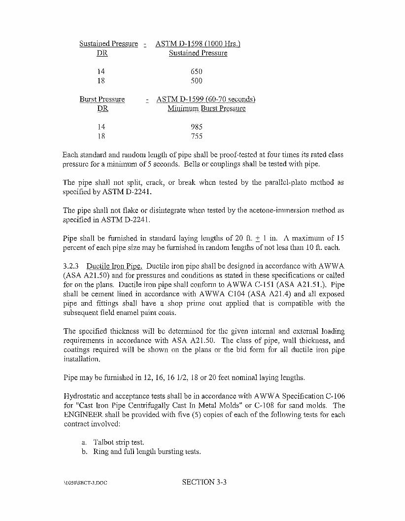
Sustained Pressure ASTM D- 1598 (1 000 Hrs.) - DR Sustained Pressure
14 18
650 500
Burst Pressure ASTM D-1599 (60-70 seconds) - DR Minimum Burst Pressure
14 18
985 755
Each standard aiid random length of pipe sliall be proof-tested at four times its rated class pressure for a miiiiinuiii of 5 seconds. Bells or couplings sliall be tested with pipe.
The pipe sliall iiot split, crack, or break when tested by tlie parallel-plato method as specified by ASTM D-224 1.
Tlie pipe sliall iiot flake or disintegrate when tested by tlie acetone-ii~inersioii iiietliod as specified in ASTM D-2241.
Pipe sliall be fumislied in standard laying leiigtlis of 20 ft. 2 1 in. A maximum of 15 percent of each pipe size may be fiiiiiished in random leiigtlis of not less than 10 ft. each.
3.2.3 Ductile Iron Pine. Ductile iron pipe shall be designed in accordaiice with AWWA (ASA A21.50) aiid for pressures aiid coiiditioiis as stated in tliese specifications or called for 011 the plans. Ductile iron pipe shall confoiin to AWWA C-15 1 (ASA A21.51.). Pipe shall be ceineiit lined in accordance with AWWA C104 (ASA A21.4) aiid all exposed pipe and fittings shall have a shop prime coat applied that is compatible with the sulxxqueiit field eiiamel paint coats.
The specified tliicluiess will be detei-niiiied for tlie given iiitenial aiid external loading requirements in accordance with ASA A21.50. The class of pipe, wall tliicluiess, aiid coatings required will be shown on the plans or the bid fonn for all ductile iron pipe installation.
Pipe may be fuiiiished in 12, 16, 16 1/2, 18 or 20 feet iioinirial laying leiigtlis.
Hydrostatic aiid acceptance tests shall be in accordance with AWWA Specification C- 106 for "Cast Iron Pipe Centrifugally Cast lii Metal Molds" or C-108 for sand molds. The ENGINEER shall be provided with five ( 5 ) copies of each of the following tests for each contract involved:
a. Talbot strip test. b. Ring and full length bursting tests.
\1050\SECT-3.DOC SECTION 3-3
c. Cheiziical analysis of pipe. d. Cei-tification that pipe was hydrostatically tested.
Any pipe not meeting the AWWA specifications quoted above shall be rejected in accordance with tlie procedure outlined in the particular specifications.
The net weight, class or iioinirial tliicluiess and sanipling period shall be marked 011 each pipe.
Pipe joints shall be rnechaiiical joint, i-ublm ring slip joint, flanged, or locked iziechanical joint equal to AWWA C- 11 1.
Exposed piping shall be field painted and the colors sliall match that of the existing piping.
3.2.4 Fittings. Cast 01- ductile iron inecliaiiical joint fittings with appropriate adapters shall be used with PVC pipe. All such fittings shall be approved by the pipe manufacturer, aiid complete data sent to tlie ENGINEER, including tlie manufacturer's approval, for review. Fittings shall comply with AWWA C-110 or C-111 and shall be manufactured for tlie size aiid pressure class of the line on which they are used.
Meclianical joint fittings shall be used with ductile iron pipe for below ground burial aiid flange fittings sliall be used for all interior piping where ductile iron pipe is used.
3.2.5 Pipe Handling. Pipe delivered to site in general, will be stored, handled, distributed, placed, j oiiied together, etc. in accordaiice with the Manufacturer's recoininelidation unless iiistiucted otlieivise by these specifications or by the ENGINEER.
3.3 Process Line Location. The CONTRACTOR shall be respoiisible for construction stakeout, based upon liorizoiital aiid vertical control points fuiiiislied by the ENGINEER. Changes in either vertical or horizontal alignment, as may be required during construction due to unforeseen obstacles or to accommodate clianges in riglit-of- way, shall be made by tlie CONTRACTOR at tlie direction of the ENGINEER. Such modifications in aligiiineiit shall be accoiiiiiiodated by the CONTRACTOR aiid tlie completed work shall be paid for under the unit prices bid for the work.
3.4 Excavation. The CONTRACTOR shall male trench excavations to only such width to provide ample room for proper construction. Sheeting aiid shoring shall be provided as required for proper safety aiid compliance with OSHA regulations. Rock excavatioii shall be taken to a depth of 6-incliesbelow bottom of pipe. If poor foundation conditions exist due to organic material or quicksand, the trench sliall be under-excavated to the depth required aiid filled with stone to obtain proper bearing capacity.
SECTION 3-4
Watchiiien or barricades, lanterns aiid other such signs aiid signals as may be necessaiy to wain the public of the dangers in connection with open trenches, excavations aiid other obstructions, shall be provided by and properly maintained at the expense of the CONTRACTOR.
Only one-half of street crossings aiid road crossings shall be excavated before placing temporary bridges over the side excavated for the convenience of the traveling public.
3.5 Blasting and Rock Excavation. The CONTRACTOR shall make his own investigation as he deem necessaiy to ascertain the sub-surface conditions to be eiicouiitered in tlie work.
All blasting operations shall be conducted in accordaiice with municipal ordinances, state and federal laws and Section 9, Explosives, of the "Manual of Accident Prevention in Constiuction, published by tlie Associated General Contractors of America, liic. Soil particle velocity shall not exceed limit set by Kentucky law. All explosives sliall be stored in conformity with said ordiiiaiices, laws and safety regulations. No blasting shall be dolie within five feet of any water mains, sewer lines, natural or manufactured gas lines, liquid petroleum product lines or other utilities. Any damage done by blasting is the responsibility of tlie CONTRACTOR and shall be promptly and satisfactorily repaired by liiiii.
The CONTRACTOR sliall use delay caps or other approved iiiethods to reduce earth vibrations aiid noise. Mud capping, as defined in the above iiianual, will not be permitted as a method of breaking boulders. No blasting shall be peiinitted on Sundays or after dark.
Prior to coiiiiiieiicing with tlie work, tlie CONTRACTOR shall, during a preconstiuction coiiference with the OWNER and ENGINEER, state clearly his approach to perfoiiiiiiig the excavations on the project. He shall be familiar with the laws and ordinances covering blasting aiid shall also give consideration to the use of liydraulically operated rock breaking devices in lieu of blasting where considered necessaiy. If blasting is not handled in an expert iiiaiiner at all times, the ENGINEER reserves the riglit to suspend blasting aiid require the work to proceed without it. Prior to blasting, the CONTRACTOR shall make his own detailed preblast survey of adjacent walks, curbs, retaining walls, house foundations, etc. to determine conditions prior to the work. Such a file of infomiation, including photographs, may be certified in such a manlier as the CONTRACTOR believes necessaiy since this is infomiation that may stand in his defense.
3.6 Storage of Excavated Material. All excavated material shall be stored in a manner that will not endanger the work aiid that will avoid obstructing roadways, sidewalks, and driveways. Hydrants under pressure, valve pit covers, valve boxes, curb stop boxes, fire arid police call boxes or other utility controls shall be left unobstiucted and
\1050\SECT-3 DOC SECTION 3-5
accessible. Gutters shall be kept clear or otlier satisfactoiy provisions made for street drainage, and natural watercourses shall not be obstructed.
3.7 Shoring, - Sheeting, and Bracing. The CONTRACTOR shall funiisli, place aiid maintain such sheeting and bracing as may be required to suppoit the sides of tlie excavation or to protect otlier structures from possible damage. All sheeting and bracing shall be removed upon completion of the work, unless peiinitted to be left in place by the ENGINEER. Any sheeting or bracing left in place shall be cut off at least two feet below the finished ground surface elevation. The cost of fuiiiisliing, placing, maintaining and removing sheeting and bracing shall be included in the unit price bid for water lines. All work shall conform to OSHA requirements.
3.8 Removal of Water. The CONTRACTOR shall provide adequate pumps, teniporaiy drains and appurtenant equipnient to dewater excavations in such a manner that will not interfere with tlie progress of work.
3.9 Bedding. All process lilies shall be bedded with 6- inches of #9 or approved equal stone under and on both sides of the pipe wliere necessaiy when rock or poor foundation conditions exist.
3.10 Tlu-ust Blocks and Anchorage. Tlmst blocks shall be installed wheiiever the pipe line changes direction, as at tees, bends, crosses, stops, as at a dead end; or at valves. The locations of thrust blocks depend on tlie direction of tlu-ust aiid type of fitting. Their size and type depends on pressure, pipe size, kind of soil, and the type of fitting. Where tlu-usts act upward (as at vertical curves) the weight of tlie pipe, the water in the pipe and the weight of the soil over the pipe should be deteiinined to make certain that tlie total weight is sufficient to resist upward movement. If there is not enough soil or if it will not compact over the pipe or it is too soft and mushy to resist inoveinent, tlien ballast or concrete may be placed around the pipe in sufficient weight and volume to counteract tlie tlx-ust. Wliere a fitting is used to make a vertical bend, tlie fitting may be anchored to a concrete tlvust block designed to key in to undisturbed soil and to have enough weight to resist upward aiid outward tlmist, since the new placed backfill may not have sufficient holding power.
Tlmist blocks shall be constructed of not less than Class B concrete confoi-ming to KBH Specification 601 and placed between the fitting and the trench wall. It is important to place the concrete so it extends to undisturbed (freshly cut) trench wall.
The tlu-ust blocks shall be sized as shown on the DRAWINGS contained elsewliere in these Specifications.
3.11 Backfill. Trenches shall be backfilled and "walked in" at once up to the height specified aiid shown in the PLANS. Backfill material shall be such that it may be compactly tamped around the pipe. No rock larger than two inches will be peiinitted within six inches of the pipe. No loose rock larger than six inches shall be less than
\1050\SECT-3.DOC SECTION 3-6
12 iiiches from the pipe. In open, unpaved, or unsurfaced areas the remainder of the fill may be tlu-own in loose and ridged up over the top of the trench. Mechanical backfilling shall be done with a rotobackfiller or angle dozer. When trenches are in the traveled areas or other places where property will be damaged by settlement of fill, sufficient coinpaction shall be made inimediately. The remainder of the diit shall be ridged up over the trench unless otheiurise ordered by the ENGINEER. The CONTRACTOR at no time shall open up more than 500 feet of trench ahead of backfill and cleanup.
Any damage to underground structures, pipes, wires, drains, etc. shall not be backfilled until tliey have been satisfactorily repaired or replaced to the original serviceability at the CONTRACTOR'S expense and as approved by the ENGINEER. settlement of backfill inay be done with water furnished by the CONTRACTOR under the direction of the ENGINEER where such will not elidanger traffic or damage property. When excavated rock is used for backfilling, it shall have sufficient dirt or fine inaterial to fill all voids and shall not be used within twelve iiiches of the pipe. All excess rock shall be cleaned up and taken away. No rock larger than two inches shall be left. hi areas to be mowed, area shall be raked and smoothed with no rock larger than one inch.
Tlie CONTRACTOR shall maintain the job in a neat and cleaned up condition at all times so as to cause miniinuni nuisance to the people. Procrastination of clean up and repair will not be tolerated. Mininiim trench dirt shall be left outside trench and no soil outside trench shall be removed. Wherever it is necessaiy to tamp the trench because of traffic, sodding, or other conditions, the ENGINEER will so instruct the CONTRACTOR who will include this cost in unit price bid. This tamping must have a coinpaction of at least 90 percent. The CONTRACTOR will be respoiisible for The tamping must be done the same day that trenching is done if there appears to be any danger of precipitation. If the weather appears to be safe, the ENGINEER inay pelinit the CONTRACTOR to complete the tainpiiig the following day. Where tamping is ordered, all excess diit must be removed the day trenching is done or the following day.
any settlement or damage due to settlement where tamping has been done.
3.12 Temporary Surfacing. All trenches in streets, roads or drives shall, following compacted backfill, receive a top layer of compacted #610 dense grade stone. Such temporaiy surfacing shall be maintained, iiicluding nights and weekends, aiid such areas shall be paved within two weeks as soon as conditions pelinit. All public or private drives shall be promptly backfilled or bridged.
3.13 Testing. The water line aiid appuitenances, as rapidly as valves are installed, shall be tested to the pressure rating of the pipe, or as directed by the ENGINEER, at point of rnaxiinuin pressure. Defective joints of pipe shall be cut out aiid replaced as directed by the ENGINEER. Cracked or defective pipe fittings, valves or hydrants disclosed in the pressure test shall be replaced by the CONTRACTOR with sound material, and the test shall be repeated until the test results are satisfactory to the ENGINEER.
\1050\SECT-3 DOC SECTION 3-7
The CONTRACTOR shall maintain required pressure for six hours and shall measure tlie amount of water necessaiy to maintain this pressure for this length of time. The amount of water used to maintain the pressure sliall not exceed five galloiis per 24 hours per mile of pipe per inch nominal diameter of the pipe except in special hardship cases.
All leaks sliall be repaired whenever or wherever tliere is evidence of a leak and tlie location is known or can be reasonably found. Water used by tlie CONTRACTOR shall be paid for by tlie CONTRACTOR at tlie rate of $2.00 per 1,000 galloiis.
3.14 Sterilization. Upon completion of a section, disinfection shall be done strictly in accordance with the procedure designated in Kentucky State Department of Health regulations which reads as follows: "All new water distribution system iiicludiiig storage distribution tanks and repaired poi-tions of or extensions to existing system sliall be tliorouglily disinfected before being placed in service by tlie use of clilorine or chlorine compounds in such amounts as to produce a concentration of not less tliaii 50 ppin and a residual of not less than 25 ppiii at tlie end of 24 hours and followed by thorougli flushing." Putting small amounts of powdered cliloriiie in each joint will not be acceptable. Wliere tlie iiew system is connected to the present system tlie CONTRACTOR will iiistall a 3/4" water meter for the CONTRACTOR on a regular water meter customer basis except that tlie CONTRACTOR will be charged a flat rate of $2.00 per 1,000 gallons.
3.15 Service Coniiectioiis. Any utility coiiiiectioiis encountered in the work sliall be presewed and protected. Wliere relocatioii or repair is required to accommodate the work, they shall be made in a inanner acceptable to the utility having jurisdiction over tlie service connection. Accommodation of service coiuiectioiis sliall not constitute any basis for extra payment.
3.16 As-Built Drawings. As each line is installed, i.e. Line A, etc., the CONTRACTOR sliall maintain a carefully marked-up set of plans to show exact "as- built" location of all valves, fire hydrants, tees, blind flanges, tie-ins to existing lines, altitude valves, etc. All drawings sliall piiipoint locations by two measured distances from proininelit landmarks. As-built drawings shall also show tlie accurate location of otlier sti-uctures and utilities adjacent to or crossing tlie work. As-built drawings sliall be periodically delivered to tlie ENGINEER.
3.17 Coordination With Utilities. Prior to construction, the CONTRACTOR shall arrange to meet with representatives of all utilities, and provide them with his anticipated work schedule. The CONTRACTOR shall have the utilities make their best deteiinination of utility locations in the areas in wliich he is working. Tlu-ougliout tlie progress of tlie work, such field markings of utilities shall be kept current. Repairs to any utilities damaged by the CONTRACTOR shall noi-rrially be perfoiined by the
\1050\SECT-3.DOC SECTION 3-8
utility at the CONTRACTOR'S expense, unless tlie CONTRACTOR and the utility negotiate other understandings and/or procedures.
3.18 Payment for Water. All water used from the OWNER supply shall be metered by meters supplied by the CONTRACTOR. The CONTRACTOR shall pay for such water niontlily at the rate of $2.00/1,000 gallons. Water lost during water liiie breakage shall be computed at the rate of $2.00/1,000 gallons. The quantity lost shall be computed on tlie basis of a discharge velocity of 7 feet/second, the diameter of tlie line, and the estimated duration of free uncontrolled discharge.
3.19 Cleanup. The CONTRACTOR shall provide effective cleaiiup of the work as it progresses. At the h i e of final inspection, no trenches shall show any undue evidence of the previous construction. All areas shall be left free of ruts due to constmction equipment aiid shall liave a clean and neat appearance witliaut rubble or debris. The areas shall not be mounded up aiid shall be coiiipletely restored, and all yards and fields shall be reseeded so land may be cultivated, mowed, etc. Straw aiid fertilizing shall accompany the seeding and the seed mixture shall match existing ground cover. If necessary to hasten proper restoration of terraces, priiicipally along ditch lines, the CONTRACTOR shall sod such areas at the ENGINEER'S direction.
3.20 Protection of Adiacent Landscape. Reasonable care sliall be taken during construction of the process lines to avoid damage to vegetation. Oiiiamental slu-ubbeiy and tree branches sliall be temporarily tied back, where appropriate, to niiiiiinize damage. Trees which receive damage to branches sliall be trimmed of tliose braiiclies to improve the appearance of the tree. Tree ti-uiilts receiving damage from equipment shall be treated with a tree dressing.
3.21 subsidiaiy in the Bid Schedule.
Payment. Payment shall be included in the payment for the work to which it is
SECTION 3-9
s 4-s
4.0 Work Included. Under this section tlie Contractor shall provide all labor, tools, equipment aiid materials to perform tlie sitework which consists of topsoil removal, excavation, the removal and proper utilization or disposal of all excavated materials, necessary borrow, fill requirements, the shaping and finishing of all excavation work to the required lines and grades, preparation of subgrade for tanks, basins, building slabs, walks aiid pavements, engineered fill for support of building or basin slabs, bacltfilling of tanks, basins, basements, aiid trenches witliin building lines, pavement replacements, aiid seeding and mulcliing.
4.1 Geoteclmical Data. Data on indicated subsurface conditions are not intended as representations or warranties of accuracy or continuity between soil boi-ings. It is expressly understood that the Owner will not be responsible for interpretation or conclusions drawn therefrom by the Contractor. Additional test borings and otlier exploratoiy operations may be made by Contractor at no cost to Owner.
4.2 Existing Utilities. Prior to cominenceineiit of work, the Contractor shall locate existing underground utilities in areas of tlie work. If utilities are to remain in place, tlie Coiitractor shall provide adequate means of protection dming eai-tliwork operations.
4.3 Use of Explosives. The Contractor (or aiiy of his subcontractors) shall not bring explosives onto the site or use in the work witliout prior written perinissioii from the Owner. Tlie Contractor shall present a blasting plan to tlie Owner and Engineer and not comiiieiice blasting operations until such plan is approved by tlie Engineer and Owner. All activities involving explosives shall be in coinpliance witli all tlie Federal, State aiid L,ocal laws aiid regulations pertaining to blasting aiid use of explosives. The Contractor is solely responsible for handling, storage, and the use of explosive materials aiid tlie safety of others in tlie area wlien their use is pei-mitted. Tlie Contractor shall review all blasting procedures witli the Owner and Engineer prior to coininencement of all blasting work. The Contractor is responsible for all blasting procedures. The particle velocity of all affected, adjacent structures shall be monitored witli a seisniograpli located at that structure. The peak particle velocity shall not exceed two inches per second at a distance of 50 feet, or aiiy velocity that may cause damage to adjacent structures. Tlie Contractor is responsible for repair of aiiy damaged structure.
No blasting shall be performed in areas where sti-uctural concrete is less than seven days old without tlie express written consent of tlie Engineer.
Protective material covering shall be used at all times to prevent flying rocks from damaging property or injuring persoimel.
A copy of the required blasting log shall be available to the Owner and Engineer.
SECTION 4- 1
4.4 Excavation. Excavatioii includes excavation to subgrade elevations iiicludiiig excavation of earth, rock, bricks, wood, cinders aiid other debris. All excavation of materials shall be included in tlie lump sum portion of tlie work and will be unclassified and no additional payment will be made regardless of type of material encountered.
Unauthorized excavation consists of reinoval of materials beyond indicated subgrade elevations or diinensioiis without specific direction of the Engineer. Unauthorized excavation, as well as remedial work directed by tlie Engineer, shall be at Contractor’s expense.
4.4.1 Clearing & Gi-ubbing. The Contractor shall cut and remove designated trees, stumps, bi-usli, logs, fences, or other materials such as sturnps, roots aiid otlier natural obstructions. No cleared or grubbed materials sliall be used in baclcfills or einbaiduiient fills.
All stumps, roots and other objectionable material shall be grubbed up so that no roots larger than time inches in diameter remain less than 18 inches below the ground surface.
All lioles and depressions left by gi-ubbing operations shall be filled with suitable material and compacted to grade.
Tlie contractor shall remove from tlie site and satisfactorily dispose of all iniscellaiieous i-ubbish including, but not limited to, masonry, scrap metal, rock, pavement, etc. that is under tlie fill or to be removed as shown on the Drawings, specified herein, or directed by tlie Engineer.
Existing improvements, adjacent property, utility and other facilities, aiid trees, plants and bi-usli that are not to be removed shall be protected from injuiy or damage.
Trees and slvubs designated to reniaiii or that are beyond tlie clearing and grubbing limits wliich are injured or damaged during coiistructioii operations sliall be treated at tlie Contractor’s expense by experienced tree surgery persomiel.
4.4.2 Excavation for Structure. Excavation for structures shall coiifonn to the elevations and diinensions shown within a tolerance of plus or ininus 0.10 feet and extending a sufficient distance from footings and foundations to peiiiiit placing and reinoval of concrete fonnwork, installation of services, otlier construction, and for inspection. All loose material shall be removed from tlie excavation just before concrete reillforcement is placed. Trim bottoms to required lilies and grades to leave solid base to receive other work
Protruding rock foiinatioiis that would interfere with unifoiin footing bearing shall be removed such that tlie structure will bear upon unifoiin engineered fill at least 24 inclies thick.
\ I OSO\SECT-I.DOC SECTION 4-2
No slab shall bear directly upon rock. All excavations shall extend to a depth that allows a minimum of six-inches ciuslied stoiie base under slab.
All necessaiy precautions shall be taken to preserve the material below and beyond the lilies of all excavation in the soundest possible condition. Any damage to the work due to the Contractor’s operations, including shattering of the material beyond the required excavation lines, shall be repaired at the expense of aiid by the Contractor. Aiiy aiid all excess excavation for the coiivenience of the Contractor for any purpose or reason, except as may be ordered in writing by the Engineer and whetlier or not due to the fault of the Contractor, shall be at the expense of the contractor. Where required to complete the work, all such excess excavation aiid over excavation shall be refilled with materials fiiiiished and placed at the expense of and by the Contractor. Slopes shattered or loosened by blasting shall be talten down at the expeiise of aiid by the Contractor.
All excavation for einbaiiluiient and structure foundations shall be perfoiined in diy weather conditions. No excavation shall be made in wet weather or where frozen materials exist without written approval.
4.5 Disposal of Material. All sui-plus excavated inaterial and/or waste inaterials shall be disposed of outside the floodplain in an area provided by the Contractor aiid approved by the Engineer. The material shall be compacted to a smooth condition aiid sloped to provide positive drainage.
Any material removed from an impoundment, river, stream or shore shall be removed from the area and disposed of outside of the floodplain as described above. Where shore areas are excavated and/or disturbed, the filial contours shall be established by using rip- rap stone or other materials as shown on the Drawings.
4.6 Sheeting and Bracing. Slieetiiig aiid bracing as may be required to safely support the sides of excavations while maintaining tlie required side slopes shall comply with the safety precautions as outlined in current and accepted safety inaiiuals, such as “Associated General Contractors Manual of Accident Preveiitioii in Constiuctioii”. Where sheeting and bracing are iiecessaiy to prevent caving of the walls of excavations aiid to safeguard the workmen, the excavatioiis shall be dug to such widths that proper allowance is made for the space occupied by the slieetiiig aiid bracing. The contractor shall perform the additional excavation required and furnish aiid put in place the iiecessaiy sheeting and bracing and shall remove the same as the excavation is filled, at his own expense.
4.7 Removal of Water. The contractor shall consti-uct and maintain all necessary cliaiuiels, flumes, and/or other temporaiy diversion and protective works; shall furnish all materials required therefore; aiid shall fui-nish, install, maintain and operate all well points, casings, pumps and other equipment for dewatering the various parts of the work and for maintaining the foundations, treiiclies aiid otlier pai-ts of the work free fi-oin water as required for constructing each part of the work. After liaviiig served their purpose, all temporary protective works shall be removed, or leveled, to give a sightly appearance aiid
\1050\SECT-4.DOC SECTION 4-3
so as not to interfere in any way with the operation, usefulness or stability of the pelinanelit structures.
4.8 Backfill and Fill Material. All material to be used as backfill inaterial shall be approved by the Engineer prior to backfilling excavations. With the exceptio11 of tlie organic debris, existing fill material, aiid topsoil, the on-site soil removed from tlie excavations will be used as fill or backfill material that is approved by the Engineer.
After clearing and stripping operations have been coiiipleted, all structure locations shall be proofrolled with a loaded pan or Iieavy pneumatic tired vehicle to densify upper soils aiid to locate possible areas which will require undercutting, reinoval and/or recompaction. This operation shall be conducted under tlie surveillance of the Engineer.
Before initiating filling operations, the Contractor sliall receive approval of fill material by the Engineer. Proctor density tests sliall be run on representative samples obtained from tlie proposed borrow material.
Where structures or other appurtenances are constructed 011 fill, the fill shall be placed in layers iiot over six iiiclies deep, as measured before compaction and be tliorouglily compacted. Compaction may be obtained by use of a slieeps foot roller or pneurnatic- tired roller. Water shall be applied as directed to obtain close adhesion between layers and all parts of the material. Fill shall be compacted to a niiniiiium of 95% of tlie Standard Proctor maxirnum dry density (ASTM Specifications D-698). A minilnuin of two compaction tests per each two feet of fill 011 a structure location shall be performed by a geoteclmical engineer.
Only suitable material approved by the Eiigiiieer shall be used for backfilling around structures. Backfilling around structures shall have material placed in layers of six iiicli depth aiid compacted by pneumatic tools or other small equipment operated by hand. hi no case shall tlie backfilliiig be allowed to obtain an elevation of one foot above any other area. It shall be uiiifoniily compacted tlu-ougliout the structure depth. Any deviation shall be cause for the Engineer to require tlie inaterial deposited to be removed and recompacted at the Contractor's expense.
All backfilling shall be done in such a inaiiiier that the pipe or structure over or against which it is being placed will iiot be disturbed. Any pipe or stiiicture damaged or moved from its proper line or grade during backfilling operations shall be removed or repaired to the satisfaction of tlie Engineer and then backfilled.
4.9 Borrow Material. Bonow material shall consist of and include tlie required excavation and proper utilization of approved materials obtained from designated areas when sufficient quantities of suitable materials are iiot available from other required excavation.
SECTION 4-4
The control of excavation in any borrow area and tlie selection of inaterials tlierefrom shall at all times be as directed by tlie Engineer. On coinpletioii of excavation, all borrow pits shall be left in a neat and sightly condition. Unless otlieiwise approved by tlie Engineer, all borrow pits sliall be so graded and dressed that water will readily drain tlierefrom, and away from all embanlunents, benns and structures. When shown on the drawings, terraces or diversions shall be coiistructed to protect tlie slopes of tlie borrow areas from erosion and shall be considered a subsidiary of this specification.
4.10 Erosion Control. Teinporaiy iiieasiires sliall be applied tluoughout the construction pelinit to control and to minimize siltation to adjacent properties and wateiways. Such measures shall include, but not be limited to, tlie use of beiins, baled straw silt barriers, gravel or ci-uslied stone, niulch, slope drains aiid other methods. Tliese temporary measures shall be applied to erodible material exposed by any activity associated with tlie constniction of this project.
4.1 1 Finish Grading. Finis11 grading shall be to tlie finislied elevations and grades shown, and shall be made to blend into confoiiiiation with remaining natural ground surfaces. All finish graded surfaces sliall be left sinootli and free to drain. Excess materials sliall be spread aiid compacted as directed. Grading within tlie consti-uctioii area and around the outside of building and structure lilies shall be perfoiined in a manner which will prevent accuiriulation of water within tlie area. Where necessary, or where shown, finish grading sliall be extended to insure that water will be directed to drainage ditches, and the site area left smooth and free from depressions holding water.
4.12 Seeding and Mulching. All disturbed areas sliall be seeded, fertilized and inulclied as shown on tlie Drawings. The application of materials shall be as follows:
4.12.1 Lime. Two tons of agricultural limestone per acre shall be required.
4.12.2 Fertilizer. Tlie following amounts of fertilizer are required per acre:
(1) Nitrogen (N) 60 lbs. (2) Phosphorous (P205) 120 lbs. (3) Potash 120 lbs.
This requireinelit can be met by applying fertilizer having an analysis of 10-20-20 at tlie rate of 600 pounds per acre.
4.12.3 Seed. Tlie following amounts of pure live seed are required per acre:
(I) KY-31 Fescue 60 lbs. (2) Peretmial Ryegrass 25 lbs. (3) Red Clover 10 lbs.
SECTION 4-5
4.12.4 Mulch. Mulch shall consist of wood fiber applied at a rate of 1600 pounds per acre, biturriiiious treated straw applied at a rate of 2000 pounds per acre or other inulch subject to tlie advance approval of tlie Engineer.
4.12.5 Execution. The seeding shall be completed within two weelts after coinpletion of the work or as soon thereafter as conditions are favorable. linmediately prior to seedbed preparation, tlie Contractor sliall apply the agricultural lime aiid fertilizer unifoiinly over the area to be seeded. The seedbed shall be prepared by pulverizing and breaking up tlie soil to a rniiiiinuin depth of two inches with a disk harrow, drag liai-row, spike tooth liai-row or similar tool. All rocks, clods, aiid undesirable material that would interfere with seeding operations shall be removed.
Tlie seeding operations shall be performed immediately after, or as soon as practicable, after tlie seedbed has been prepared. Tlie seed sliall be drilled or broadcast uniformly over the seedbed with regular approved type of equipment or metliod acceptable to tlie Engineer. The seeded area shall be passed over with a llai-row or cultipaclter to help cover inore seed and improve seedling establishment. Excessive tillage sliall be avoided. After all construction work is complete, prior to filial payment, all exposed areas shall be cleaned and left in a sightly manner. All unused material shall be removed from tlie site.
The Coiitractor may liydroseed aiid hydromulch if tlie following requirements are met.
1. Tlie individual seed quantities shall be increased by 20%.
2. The inulch sliall be a processed hay or straw applied at a rate of 3/4 toil per acre with 80 Ibs. per acre of an organic tacltifier.
3. Tlie liydroseeder slurry shall not be allowed to drop below a pH of 5 .O.
Tlie Contractor shall be responsible for tlie maintenance of all work under this section until final acceptance. Adequate protection of exposed slopes sliall be provided at all times to prevent excessive erasion. No work will be accepted unless tliere is evidence of healthy growtli arid sufficient cover to prevent erosion.
Work executed under tliis section sliall be guaranteed for one year with the guarantee beginning on tlie date of filial acceptance of all work under this Contract. Any seeded areas of tlie site which are found to not have an adequate growth of cover during the guarantee period, shall be reseeded as soon as weatlier conditions permit, at no cost to the Owner.
4.13 Bituminous Pavement. At tlie coinpletion of constniction, all roads sliall be regraded aiid areas to be paved with bituminous sliall be prepared for a prime coat of emulsified asphalt RT-2 applied at tlie rate of 0.35 gallon per square yard. A two-inch thick Class “I” Bituminous Coiicrete Binder shall be placed above the prime coat in accordance with the Kentucky Bureau of Highways Specifications. The three feet wide
\1050\SECT-4.DOC SECTION 4-6
shoulders of dense graded aggregate shall be graded aiid rolled to the top of the binder course and shall slope out and away frorn pavement.
After roadway has been traveled for a period of at least 60 days arid all plant construction aiid piping is complete, a 1 1/2-inch thick layer of Class “I” Bituminous Concrete shall be placed as a finished aiid complete roadway surface.
The roadways and parking areas shall be constructed in accordance with good paving practices. Problems due to unequal settlement shall be properly handled to prevent an uneven road surface. hi any case, the Contractor is responsible for providing roads with neat lilies and smooth surfaces tlu-oughout the plant site.
Damage to the existing paving caused by the Contractor will be patched to the full road width in the damaged area. All patching shall be to neat lilies and even surfaces.
4.14 Payment. Payrielit for all excavation aiid fill work shown on the Drawings and herein specified, that is required to complete the clearing, grubbing, site grading, roads, stixctural excavation, borrow excavation, bacltfill, sheeting, shoring, topsoil, ci-ushed stone or gravel, drainage, pumping, eiiibaiiluiient fills, pavement, seeding and inulching, and any other excavation aiid fills required to coiiiplete the work as sliowii 011 the Drawings shall be included in the work to wliich it is subsidiaiy in the Bid Schedule and no iiieasureineiit of the quantities will be made. The coiitours and elevatioiis of the present ground are believed to be reasonably correct but are not guaranteed. The Contractor shall satisfy himself by actual examination of tlie site of work as to the existing elevations and coiitours aiid the amount of work required under this section.
SECTION 4-7
VA
5.0 The work consists of the demolition aiid removal of the existing 65,000 gallon standpipe storage tank located off of East Kentucky Highway 80 as shown on tlie Plans. The work shall include removing all reinnants of the tank structure, foundation, valve vault aiid all other related appurtenances to a point one foot below existing ground level.
Scope of Work.
The Contractor shall fuiiiisli all labor, materials, equipment, tools, supplies, traiispoi-tatioii and other incidentals iiecessaiy to successfully complete the project.
5.1 Owiiersliiu of Materials. specifications shall become the property of the successful bidder.
All salvaged materials except those noted in these
5.2 Specifications Wliicli Apply. The General Conditiolis aiid Supplemental General Conditions, both of whicli are a part of these specifications, shall apply except as altered or iiiodified in these Teclviical Specifications.
5.4 Disposal of Materials. All materials aiid debris resulting from tlie demolition operations shall be disposed of by tlie Contractor at locations outside the project site in a maimer that will coinply with all local, State and Federal regulations and as per OSHA (29CFR192663 aiid 354) and EPA Regulations.
A suitable disposal site shall be an-anged for aiid secured by the Contractor, aiid he shall assuiiie full responsibility for acceptable dispositioii of the material as well as for aiiy damages resulting from liis disposal operations. Filial acceptance of tlie work will iiot be made until the disposal areas are in acceptable coiiditioii with respect to tlie Contractor’s obligations as expressed above. The Contractor shall pay for aiiy required pennits or dumping fees.
Access to the site is available from East Kentucky Highway 80.
The Contractor shall provide the District with infonnatioii aiid evidence coiiceiiiing disposal details and ail-aiigeiiieiits. Salvaged materials may be stored on the site temporarily, but not beyond seveii days from tlie time of removal fi-om their original position.
5.5 Retained Salvaged Materials. Kentucky 80 water storage tank includes the following:
Iteins to be salvaged from tlie existing East
A. All Teleinetiy Related Equipment.
SECTION 5-1
5.6 Execution. The Contractor shall iiot proceed with tlie deiriolitioii aiid reinoval of the existing 65,000 gallon water storage tank until after the coinpletioii and successfiil operation of the District’s new 300,000 galloii elevated water storage tank.
5.7 Working Area. The working area is shown on the tank aiid water main location map 011 the Drawings. The working area is defined as tlie new 100’ x 100’ x 155.27’ x 109.87’ lot for tlie new 300,000 gallon elevated water storage.
5.8 Pipe Disconnection. The Contractor will be responsible for the discoiiiiectioii and capping of tlie existing water lilies to the water talk as sliowii 011 the Drawings and as directed by tlie Engineer. This will be done before the tank demolition is started.
5.9 Exaiiiinatioii of Site. Prior to presentation of Bid Proposal, the bidder or qualified representative of the bidder must visit the project site aiid review tlie coiiditioiis in tlie field.
5.10 Filial Cleanu~. The Coiitractor shall reinove all salvageable aiid iion-salvageable materials, rubbish, and other debris from the site. The site shall tlieii be leveled smooth to tlie contours existing prior to the deiiiolition operations.
5.1 1 Basis of Payment. Payiieiit shall be made on the basis of teiiiis agreed ~ipoii on the proposal foiiii.
5.12 Restoration. topsoil, seeded with a lawii mixed seed, aiid iiiulclied at a rate of one ton per acre.
Any areas affected by the demolition procedures will be filled with
5.13 subsidiaiy in the Bid Schedule.
Payliient. Payneiit shall be included in tlie payiient for tlie work to which it is
SECTION 5-2
NT
6.0 Wosk liicluded. Under this item tlie Contractor shall provide all labor, tools, equipment, and materials to install the hydrants as shown 011 the drawings aiid as directed by tlie Engineer.
5.1 Materials. The hydrant sliall conform to all of the applicable requirements of ANSUAWWA C502 Standard. They shall have a sealed oil reservoir that will provide positive lubrication of the stein tlmads and bearing surfaces each time tlie liydraiit is opened. The hydrant shoe shall be designed for inaxiinuiii full flow aiid the hydrant working pressure shall be 200 PSI. The hydrant shall be two way type with two 2 1/2- iiicli opeiiiiigs or t h e e way type with two 2 1/2-inch openings and one 4 1/2-i1icli opening as shown on tlie details/drawings aiid as outlined in the Bid Schedule.
6.2 Installation. Tlie hydrants shall be set in accordaiice with the detailed drawiiigs coinplete with gate valve aiid connecting pipe. The hydrant shall be installed perpendicular to the surrounding ground surface and the hydrant riser shall be coiiipletely buried. Tlie depth of buiy shall be the same as the adjoining water line. Tlie shoe of tlie hydrant shall be encased in Class B concrete and the concrete shall extend to undisturbed earth. Gravel shall be placed around tlie hydrant on top of the coiicrete tluust restraint aiid at tlie weep hole a miiiinium depth of twelve iiiclies in depth. Select eai-tli backfill shall be compacted to fill the reniaiiiiiig excavated void aiid tlie surface shall match tlie sui-roundiiig surface. The liydraiit shall be secured to tlie coiiipanion gate valve by means of a hydrant adapter and pipe restrainer or by other approved means. Tlie hydrant adapter shall be tlie swivel by solid adapter with swivel gland type as manufactured by Tyler Pipe/Union Foundiy Company, or approved equal. The direct coimection of iiiecliaiiical joint (MJ) fittings betweeii the valves tlie tee aiid shall be made using Foster adapters wliere flus11 hydrants are indicated on the Coiistiuctioii Drawings. Tlie Foster adapters sliall be constructed of ductile iron aiid coinply with applicable AWWA Standards. Tlie Foster adapters shall be designed for a worltiiig pressure of 200 psi and to witlistand a test pressure of 250 psi. Foster adapters shall be lined and coated in accordance witli AWWA C104 and C l 10. Foster Adapter shall be as manufactured by Tiifact Corporation, or approved equal. The pipe restrainer shall be Grip Ring@ Pipe Restrainer as manufactured by Roinac Industries, Tiic., or approved equal. The hydrant shall be coated with a priiiie coat and two finish coats of paint as suggested by the manufacturer aiid approved by the Engineer. The shop drawings shall indicate the coating and color proposal.
6.3 Pawilelit. The unit price bid shall constitute full conipeiisatiori for fuiiiisliing and installing the hydrant, gate valve, up to ten feet of water line, and any associated pipe fittings required to install the hydrant to the main water line.
SECTION 6-1

13-
A
MAP(S)
RECEIVED ON: March 22,2013


![[XLS]dep.ky.govdep.ky.gov/formslibrary/Documents/TankSpreadsheetv6a.xls · Web viewHints Glossary Tank#10 Tank#9 Tank#8 Tank#7 Tank#6 Tank#5 Tank#4 Tank#3 Tank#2 Tank#1 Summary Instructions](https://img.pdfslide.net/doc/110x75/5ab43ede7f8b9a1a048ba1de/xlsdepky-viewhints-glossary-tank10-tank9-tank8-tank7-tank6-tank5-tank4.jpg)


![Crystal River News. (Crystal River, FL) 1895-09-13 [p ].ufdcimages.uflib.ufl.edu/UF/00/08/66/14/00095/00095.pdft t-ot llrls j adV 1t j IF i I1 JfI WJIOtI the o ci t jti f brat Vj so](https://img.pdfslide.net/doc/110x75/5e4fa0b35d2fd97bf31a18e1/crystal-river-news-crystal-river-fl-1895-09-13-p-t-t-ot-llrls-j-adv-1t-j.jpg)