Embed Size (px)
Citation preview
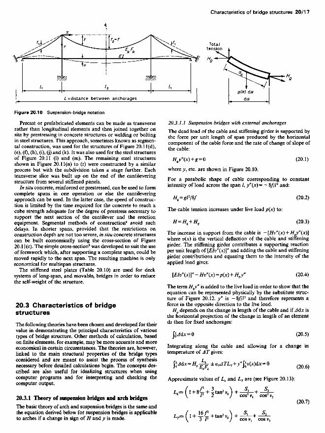
Figure 20.10 Suspension-bridge notation
Precast or prefabricated elements can be made as transverserather than longitudinal elements and then joined together onsite by prestressing in concrete structures or welding or boltingin steel structures. This approach, sometimes known as segmen-tal construction, was used for the structures of Figure 20.1 l(d),(e), (f), (h), (i), (j) and (k). It was also used for the steel structuresof Figure 20.11 (1) and (m). The remaining steel structuresshown in Figure 20.11(n) to (r) were constructed by a similarprocess but with the subdivision taken a stage further. Eachtransverse slice was built up on the end of the cantileveringstructure from several stiffened panels.
In situ concrete, reinforced or prestressed, can be used to formcomplete spans in one operation or else the cantileveringapproach can be used. In the latter case, the speed of construc-tion is limited by the time required for the concrete to reach acube strength adequate for the degree of prestress necessary tosupport the next section of the cantilever and the erectionequipment. Segmental methods of construction8 avoid suchdelays. In shorter spans, provided that the restrictions onconstruction depth are not too severe, in situ concrete structurescan be built economically using the cross-section of Figure20.1 l(c). The simple cross-section9 was developed to suit the useof formwork which, after supporting a complete span, could bemoved rapidly to the next span. The resulting machine is onlyeconomical for multispan structures.
The stiffened steel plates (Table 20.10) are used for decksystems of long-span, and movable, bridges in order to reducethe self-weight of the structure.
20.3 Characteristics of bridgestructures
The following theories have been chosen and developed for theirvalue in demonstrating the principal characteristics of varioustypes of bridge structure. Other methods of calculation, basedon finite elements, for example, may be more accurate and moreeconomical in certain circumstances. The theories are, however,linked to the main structural properties of the bridge typesconsidered and are meant to assist the process of synthesisnecessary before detailed calculations begin. The concepts des-cribed are also useful for idealizing structures when usingcomputer programs and for interpreting and checking thecomputer output.
20.3.1 Theory of suspension bridges and arch bridges
The basic theory of arch and suspension bridges is the same andthe equation derived below for suspension bridges is applicableto arches if a change in sign of H and y is made.
20.3.1.1 Suspension bridges with external anchorages
The dead load of the cable and stiffening girder is supported bythe force per unit length of span produced by the horizontalcomponent of the cable force and the rate of change of slope ofthe cable:
#,y(*) + * = 0 (20.1)
where y, etc. are shown in Figure 20.10.
For a parabolic shape of cable corresponding to constantintensity of load across the span /, y"(x) = - 8///2 and:
Hg=glW (20.2)
The cable tension increases under live load p(x) to:
H=HK + Hp (20.3)
The increase in support from the cable is — [Hv" (x) + H^(X)]where v(x) is the vertical deflection of the cable and stiffeninggirder. The stiffening girder contributes a supporting reactionper unit length of [EIv"(x)]" and adding the cable and stiffeninggirder contributions and equating them to the intensity of theapplied load gives:
[EIv"(x)]" - Hv"(x) =p(x) + Hfy" (20.4)
The term H^y" is added to the live load in order to show that theequation can be represented physically by the substitute struc-ture of Figure 20.12. y" is — 8///2 and therefore represents aforce in the opposite direction to the live load.
Hp depends on the change in length of the cable and if A&x isthe horizontal projection of the change in length of an elementds then for fixed anchorages:
JjJdX = O (20.5)
Integrating along the cable and allowing for a change intemperature of A T gives:
fcW*-*Pl^ iMJV^fr-Wfc-O (20.6)
Approximate values of Lk and L7 are (see Figure 20.13):
L^ (l+8-£ + ̂ tan2 V0) + -^-+ ~4-* \ /2 2 °/ COS2V1 COS2V2
(20.7)
L1^(I+ ̂ + tan2V0) +JjU JL.
Totaltension
L= distance between anchorages

Equations (20.4) and (20.6) must be satisfied simultaneouslyand, although this makes the problem nonlinear, the correctvalue can be satisfactorily determined by interpolation bysolving for two assumed values of H. Each assumed H gives anincorrect solution to Equation (20.6) and, assuming the errorvaries linearly, the correct value of H can be found. For eachassumed value of//, the structure behaves as a simple beam andinfluence lines can be constructed for bending moments, etc.,and for fo(x)dx. Hawranek and Steinhardt10 suggest that for aparticular loading case the bending moment and shear forces befound from both sets of influence lines as well as the ftv(x)dxvalues. H is found by interpolation and then the final bendingmoments and shears are found by interpolating between the twosets of values already found from the influence lines.
Typical results for a continuous stiffening girder are shown inFigure 20.14.
The above treatment follows that given by Hawranek andSteinhardt10 who also give a comprehensive set of standard
solutions for the substitute girder. The result quoted belowillustrates the form the solutions take. Using:
It = HIEI
For the load case of Figure 20.15, deflections as a function of xare given by:
V(X9 O = PG(X1 &
•p^ff (i-jV^^*'"0] for{H L / \ / / /i/sinh/// J(20.8)
v(x,Q=PG(x9Q
"A[K-?)-^a?-*] -«-
Figure 20.11 Elevated roadways, (a) Westway, Section One; (b) Tunnel relief flyover, Liverpool; (c) Vorlandbrucke Obereisesheim;(d) llltal; (e) West Gate approach viaducts; (f) Westway, section five; (g) Bendorf, section at pier; (h) Mancunian Way; (i) Gladesville;(j) London; (k) Narrows; (I) Annacis; (m) Severn; (n) Europa; (o) Duisberg-Neuenkamp; (p) Concordia; (q) Kniebrucke; (r) Sava I;(s) Zoo

G(x, <!;) is known as a Green's function.
And:
F[Q = Jp(X)Ax
_ , / 2 r« / -0_ 1 / . cosh//(//2-O \1"^ Hl 2/2 W2 V coshM//2) / J
(20.9)
Computers can be used to analyse suspension bridges either byfollowing the above approach or by means of standard frame-work programs provided the interaction of axial loads anddeflections is allowed for. In other words, the change in geo-metry of the cable is considered. In some programs the axialloads must be stated as part of the data in the same way that H is
assumed in obtaining a solution to Equation (20.4). In others,an interactive process produces the correct axial forces. Thestructure solved can include the actual system of suspenders,tower properties, etc. or can be a very simple solution of thesubstitute structure of Figure 20.12.
Figure 20.12 Substitute girder

20.3.1.2 Self-anchored suspension bridges
The horizontal component of the cable tension can be resistedby the stiffening girder which then acts as a laterally loadedcompression member between suspenders. The net tension onthe structure is therefore zero and the substitute girder has azero axial load acting on it. The structure is substantially linearin its response to live load whereas the externally anchoredbridge has an increasing stiffness with increasing deflection.
20.3.1.3 Arch bridges
The design of arches is based on the thrust line following theshape of the arch so that there is either no bending moment or areduced bending moment in the arch member.
The shape of arch can only satisfy one condition of loadingwithout bending moments being developed. Temperaturechanges, creep, foundation movements and imperfections must,however, introduce some bending in all but the three-hingedarch. In a bridge structure, live loading will produce a varyingdistribution of loading which will introduce bending. Clearly,the higher the proportion of dead load the more nearly can thearch be designed to be in pure compression.
The most common shapes are the circular arch, the parabolicarch and more recently the inclined leg frame (Figure 20.16).Loadings over the whole of (c) can be examined in two stages,which enables a design to be produced before detailed dimen-sions are known (Figure 20.17).
Arches for bridges frequently have continuous beams sup-porting the deck as in Figure 20.18.
At the design stage, since the dead load carried by the deckwill depend on the construction method and the thrust jackedinto the arch, the structure is to some extent determinate but,clearly, some bending of the deck beams between supports isintroduced. The system can be represented as in Figure 20.19where №*w/2/8/.
At the preliminary design stage, live loading can be examinedby splitting it into symmetrical and antisymmetrical compo-nents (Figure 20.20). The symmetrical system will produce to afirst approximation small bending moments and the asymmetri-cal system is equivalent to a simple beam with half the arch span(zero thrust due to opposite effects of load).
The local effects of loading on the deck can always beexamined as a beam between columns and the overall behaviourcan be seen as that of an arch with a total EI of EI6^ + £/arch.The bending moments produced in the parts will be in propor-tion to stiffness.
Figure 20.13 (After Hawranek and Steinhardt (1958) Theorie und Berechnung der Stahlbrucken. Springer-Verlag)
Influence linefor Hf
Take loadedlength thus
Influence linefor bendingmoment atmidspan
Figure 20.14 Influence lines, (a) Influence line for Hp; (b) for bending moment at midspan. (After Hawranek and Steinhardt (1958)Theorie und Berechnung der Stahlbrucken. Springer-Verlag)

Figure 20.17 Two-stage analysis of inclined leg frame
Arches may require correction for deflections since the thrustwill magnify these in the same way that a strut is affected by endload. A two-hinged arch with a uniform loading buckles as inFigure 20.21 and to a first approximation the effective length ofthe strut is 1/2. The magnification of moments can be found asfor a strut using l/(\-H/HCT) as the factor. Critical loads areavailable for a variety of cases as in Table 20.11.
Equation (20.4) for suspension bridges is applicable to archeswith changes of sign in H and y. The nonlinear effects ofdeflections can be determined using that equation or the substi-tute beam in compression instead of tension. Computer pro-grams can be used to analyse arches in the way alreadydescribed for suspension bridges but if HjHCT is small it isunnecessary to use programs which allow for changes of geo-metry.
Out-of-plane deflections can cause buckling or significantstresses in single arches or arches not braced laterally. Thiseffect can be investigated readily using a grillage programmewhich allows for the interaction of axial loads and transversedeflections. The plane of the grillage must be considered as theplane of the arch for that purpose.
20.3.1.4 Tied arches
In the tied arch, the thrust is balanced by tensile forces in thestiffening girder which simplifies the in-plane behaviour of thestructure since there is no net thrust on the structure. In-planebuckling is thus prevented but out-of-plane buckling is stillpossible.
Table 20.11
/, O 0.1 0.2 0.3 0.4 0.5
For a twohinged arch 39.4 35.6 28.4 19.4 13.7 9.6 k£J
For a fixed //cr = —p-arch 80.8 75.8 63.1 47.9 34.8 24.4
20.3.2 Bridge girders of open section
The cross-girder and bracing members are shown as brokenlines in Figure 20.22 since they do not affect the girder undertwisting loads unless it has torsionally stiff members.
To find q (Figure 20.23) it is necessary to consider theequilibrium equation of the top flange (cf. simple beam theory).It is assumed that the shear force on the top flange is zero asshown and that the second moment of area of the top flangeabout a vertical axis is /T.
Taking moments in a horizontal plane:
, , (<7 + d<r) abgdx=-b/2-^-b/2Ir
. 2/T=dffVTherefore:
A A 2/Tqdx = da-^
This is the same equation as that used for simple beams if theirtop flange area A is made equal to 2IT/b2. It follows that q can befound by considering an equivalent simple beam with A^replacing the deck and acted on by shear forces Q (Figure20.24). Note that Q is not altered by horizontal shears and istherefore the same as in a simple beam loaded by W.
Figure 20.16 Arches with the loading that produces no arch member-bending, (a) Circular arch; (b) parabolic arch; (c) inclined leg frame
Figure 20.15 (After Hawranek and Steinhardt (1958) Theorie und Berechnung der Stahlbrucken. Springer-Verlag)
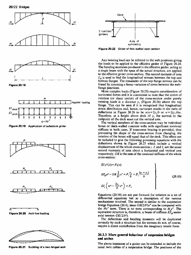
Figure 20.22 Girder of thin-walled open section
Any twisting load can be referred to the web positions givingthe loads to be applied to the effective girder of Figure 20.24.The bending moments produced in the effective girder, acting asa single beam with the span of the actual structure, are appliedto the effective girder cross-section. The second moment of areaIv
eff is used to find the longitudinal stresses between the top andbottom flanges. The remainder of the top flange stresses can befound by assuming a linear variation of stress between the web-flange junctions.
More complex loads (Figure 20.25) require consideration ofhorizontal forces and it is convenient to note that the centre ofrotation (or shear centre) of the cross-section under purelytwisting loads is a distance >>, (Figure 20.26) above the topflange. This can be seen if it is recognized that longitudinalstrain distribution and, hence, curvature results in the ratio ofdeflections in Figure 20.26 to be w/v = 2yjb or w = 2(yjb)v.Therefore, at a height above deck of >>, the normal to themidpoint of the deck must cut the vertical axis.
The vertical members of the cross-section may be individualboxes or thick-walled concrete webs with significant torsionalstiffness in both cases. If transverse bracing is provided, thuspreventing the shape of the cross-section from changing, therotation of the boxes will equal that of the deck. This effect canbe included to give the following governing equations with thedeflections shown in Figure 20.25 which include a verticaldisplacement of the whole cross-section z. /, and /, are the usualsecond moments of area about a horizontal and vertical axisrespectively. GK is the sum of the torsional stiffness of the wholecross-section:
EIjT(X) = P1(X)
Pf1 ifr—ftY ^ „ _ p C2 (g|+.X|)£V GK^2V -P1J+P1-— (2Qio)
n, .(H* -^v)=P2
Equations (20.10) are not put forward for solution as a set ofdifferential equations but as a description of the variousmechanisms involved. The second is similar to the suspensionbridge Equation (20.4), since GK(2/b2)v" can be compared withthe Hv" term. There is no term corresponding to H^". Theequivalent structure is, therefore, a beam of stiffness EIl
eff underaxial tension GK(2/b2).
The deflections and bending moments will be duplicatedcorrectly by such a structure but the stresses do not, of course,require a direct contribution from the imaginary tensile force.
20.3.3 More general behaviour of suspension bridgesand arches
The above treatment of a girder can be extended to include theusual twin cables of a suspension bridge. The positions of the
!-sectiongirders
Deck
Axis ofsymmetry
Figure 20.21 Buckling of a two-hinged arch
Figure 20.20 Arch live loading
Figure 20.19 Application of substitute girder
Applied loading
Figure 20.18

Figure 20.23 Loading and stresses on thin-walled open section
cables are shown in Figure 20.27. Equations (20.10) becomeextended into:
(1) EI2z*(x) - (//, + H2)Z-(X) - (H, - H2) ^- v"(x)
= P1(X) +(Hfl +HJy"
(2) EII^(X) -GK^2 v"(x) - (H, + H2^v-(X) - (H1 - H2) ^ z"(x)
(20.11)
-P3+P3+P$ + (H,t + Hjyt
(3) £/, (V(X)- ^v*(x)^ =/>„.
The terms underlined are fairly small and can be neglected,which leads to (1) and (2) being independent equations in z andv.
Further, if purely torsional loading is assumed, Hp]^Hp2 = Hp
and writing H, + H2 = 2H the second equation becomes:
EIf^(X)- (GK^2 +2H^ ) v"(x)
-P e* +P (£l±Zi)+2// ev"~^~b+^~~b~~+1H"by (20.12)
Figure 20.25 Overall loading and displacement
Flexural rigidity -£7^
Figure 20.24
Neutralaxis

Figure 20.27 Change in cable position
For each cable the condition \^A dx = O must be satisfied leadingas before to the correct value of Hp. Equation (20.12) is clearlyof the same form as the ordinary suspension bridge equationfor vertical deflections except that EIv
eff replaces EI andGK(2/b2) + 2H(e2/b2) replaces H. Therefore, the same results canbe used to solve this equation.
The above equations may be used to investigate aerodynamicand other vibrational effects as well as live loading. The abovetreatment follows that of Hawranek,10 but the effective beamconcept has been used in order to give the equations morephysical significance. Hawranek works in terms of a warpingfunction and relates loads to the shear centre. Hawranek andSteinhardt give, however, a number of useful results for thenatural frequency of various systems.
Horizontal deflections due to wind may produce a significantlateral component of the cable force but the complete propertiesof the structure must be known before the effect can bedetermined, e.g. the tower stiffness influences this type of
behaviour. It is not considered in the above equations. For agiven system, approximate results can be estimated by simplecalculations but rigorous results can be obtained using, forexample, a grillage programme which includes the interaction ofaxial forces and deflections. The plane of the grillage must beassumed to be the plane of the cable for this purpose.
20.3.4 Single-cell box girder
The full torsional stiffness of a single cell, 4A2G/$(l/t) ds is onlymobilized if the twisting forces are applied in the cross-section ina distribution corresponding to a constant shear flow aroundthe box. A structure with effective diaphragms at the supportsonly (Figure 20.28(a)) and with hinges at the long edges, has notorsional stiffness under the twisting loads shown. They arecarried in differential bending. The associated stresses arewarping stresses (Figure 20.29). Figure 20.28(a) shows how thewarping moments M0 are found and Figure 20.28(c) shows theeffective beams carrying equal and opposite values of M0. Theproperties of one of the effective beams can be calculated fromthe following values:
Top flange area . _ 2/TAr~~%
Web as in actual box beam
Bottom flange area . _ 2/BB ~~¥
where /T and /B are, respectively, the second moments of area ofJhe top flange assembly and the bottom flange assembly aboutthe vertical axis of symmetry.
Figure 20.28 Equivalent I-beam
Figure 20.29 Warping stress distribution
Stiffeninggirder webposition
Figure 20.26 Twisting about centre of rotation
Centreof
rotation

The warping stresses in the effective beam are determined as innormal beam theory and the remaining warping stresses in theflanges can be found by assuming a linear variation of stressacross the top and bottom flanges.
Complex box structures can be solved most economically bysuitable finite-element programs. Elaborate calculations byalternative means are not justified, but in order to understandthe behaviour of box structures or for structures where anapproximate result shows that further investigation is unneces-sary, the following methods are of value.
20.3.5 Boxes with discrete diaphragms
Steel boxes usually have a number of diaphragms formed from alattice system or solid plate and sometimes unbraced frames.The following influence-coefficient approach is one of severalmethods of dealing with such structures acted upon by twistingloads.11-12
The structure is rendered statically determinate for twistingloads by releasing the warping moments at each diaphragm thuspermitting relative warping rotations to occur (Figure 20.30).Each bay of the box between diaphragms acts in a similar way tothe box of Figure 20.28. At each diaphragm, however, instead ofthe twisting moments being taken by the supports, they are fedthrough the diaphragms into the box as pure torsion. Thediaphragms then act as a series of elastic supports to theequivalent beam as shown in Figure 20.31 except that at theinitial stage the beam acts as if hinged at each spring anddiaphragm and is therefore determinate.
The stiffness of the diaphragms k is found from the relation-ship between the distortional force system, Figure 20.32(a),which is the distortional component of Figure 20.32(b), and thedistortional deflection system shown in Figure 20.33(a).
P _ applied distortional forcesv distortional deflection
The deflections of the diaphragms or springs induce relativerotations at each hinge. The rotations at the releases areincreased by the warping produced by the torque fed into thebox at each diaphragm and the effect of the load betweendiaphragms. Denoting O1 as the relative rotation due to springdeflections and local loads, the total relative rotation is:
a-e + Q±i-&°'^+-f j (20.13)
Jr+] Jr
where Q is the torque T divided by b, and/is the shear stiffnesslinking torsion and warping rotation:
7 G 8c2
J E b/t3 + b/t2-2c/ti (20.14)
where r and r + 1 refer to bays between diaphragms as in Figure20.30.
The influence coefficients for solving the series of compatibilityequations are:
EO - lE°"->-a,_}a^
Ff, =:£.-_!_-JL IV I + -L ̂ J-Lt>"-> 6Ir aj", a, L U, a,-J *,-,
+ C1+-Hl\ar a,+ , Jk,J
F0 - a + ̂ iL + __L + ' + _!_W"- 31, + 3/,+ 1
+ «/* + a,+ I/-,tl O2A-,
+ (! + _ L V ' + '\ar ar+, ) kr a2
r+lkr+]
M - a^ - 1 - 1 U l + M^-^"+1 6/r+1 ar+lf*r+l ar+ll\ar+2 ar+J kr+]
+ V^ + aJfcJ (20.15)
«u,= —Vr-r+2 ar,2ar+lkr+]
where the effective distortional bending stiffness of the box inbay r is EIr and an additional /* is a shear stiffness for thewarping rotation produced by distortional shears in the box:
f - G 8c2
J E b/t3 + b/t2 + 2c/tl (20.16)
The various results given above can be found from concepts ofvirtual work using the mechanism shown in Figure 20.34consisting of a series of shear webs and booms of axial stiffness.It can be used to obtain more general results such as those forboxes of trapezoidal cross-section." 13
The warping produced by torsion results in stresses only ifthere is a change in torsion and therefore incompatible warping.Longitudinal stresses act to remove the lack of continuity. Anupper bound estimate of these stresses can be made by assumingthat the cross-section cannot deform. The warping momentsproduced by a change in torque T= Pb is:
X= ^ ^^expl-V(T1Y/,)*] (20 17)
where ;c is the distance from the cross-section at which thechange occurs.
Figure 20.30 Box with discrete diaphragms
Diaphragm r-2

Figure 20.32 Distortional force system
The distribution of shear forces associated with warping stressescan be found from the warping stress distribution (Figure20.35). Starting from the edge of the cantilever and assuming CTis the change in longitudinal stress over a unit length:
q- f aidsJ O
where q is the shear flow rt.
The complementary shear to q is on the face of the cross-section.The shear at the centre of the top flange can be assumed to bezero at the first stage of the calculation, which enables a simpleshear system to be found. A pure torsional shear flow must beadded to remove any component of pure torsion acting on thecross-section.
20.3.6 Box beams with continuous diaphragms
The frame action of the webs and flanges in concrete boxesprovides a continuous resistance to distortion; consequentlyspecial diaphragms are not usually necessary except at disturb-ances such as bearings and other support points.
Smaller steel box beams which rely on the stiffness of the sidesplus the frame action of web and flange stiffness or larger boxbeams with special frames which leave the interior of the boxunobstructed, have similar characteristics to the concrete boxes.Frames are generally flexible compared with braced or platediaphragms but stiff frames can be made which will haveproperties that can only be explored fully by a treatment whichis suitable for discrete diaphragms. The validity of the followingapproach for steel boxes can be determined from the halfwavelength which should be greater than twice the spacing ofthe frames.
The effect of twisting loads P applied at the corners of the webon the vertical deflections caused by distortional bending of thebox and allowing for the diaphragm action of the cross-sectionis:14
•-£H'[i*i(A-7)]-*
4a[£-i(A -j)] s i«AJ (20.I8)
assuming that the distance to a support is infinitely long. EI6 isthe effective distortional bending stiffness of the box, and k is thediaphragm stiffness per unit length. A is defined by:
V=-±-4£/,
and:
a = (A2 + k/4Ef*y/2, P=(P- k/4Ef*y2
The generalized warping stress resultant is:
P r _ / 1 , A2 / f l \X=We lP(2+-f)COSpX
+ aH + y)Sin/*] (20.19)
Fromequivalent
beam
Associateddeflection
2</ =2 x verticaldeflection of
equivalent beam
Figure 20.33 Cross-section distortion
Associated twistingforces
Figure 20.31 Equivalent beam on elastic supports
Transverseframes
Diaphragm
Springs of stiffness k
Diaphragm
Equivalentbeam

Figure 20.35 Half box
If the properties of the box are within the range A2 - (k/4Ef*) < Othen /?= (k/4Ef* — >12)1/2 replaces P and hyperbolic functions areused.
The half wavelength is n/2fi.In many cases, the effect of shear is not considerable and
a = ff = L The equations then simplify into the standard beam onelastic foundation results. The above equations include, how-ever, the effect of the change in torque due to the twisting loadsP and in order to correct the results of beam on elasticfoundation theory the warping moment of Equation (20.17)should be added. The correction is likely to be of most signifi-cance in boxes which are much wider than their depth.
The above equations are valid for boxes of trapezoidal cross-sections if the concepts are generalized as was illustrated byDalton and Richmond.13
20.3.7 Box girders with cantilevers
The advantages of box girders over structures of open cross-section are sometimes only marginally linked to structuralefficiency. However, where a compact structure is to carry amuch wider deck, producing a large cantilevered section, thetorsional stiffness and strength of the box is of primary import-ance. The importance of the interaction of the cantilever and the
box and the magnitude of the stresses is correspondingly greatsince any loss of torsional strength and stiffness could result in amajor increase in the shear stresses and longitudinal stresseswith a corresponding reduction in the load factor.
The three types of cantilever in Figure 20.36 show:15
(1) Transmission of torque Pe into twisting couple which mustbe resisted by diaphragm action.
(2) Cantilever bracket which, in the position shown, produceshorizontal loads which are in the correct ratio to the verticalshear P to give a torsional shear flow without diaphragmaction. In a concrete box the transverse moments in walls ofthe structure would be small.
(3) The relative stiffness of the web results in most of thecantilever moment being taken by the web which produceshorizontal forces corresponding to a brace at any positionof the load. The transverse moments in the walls aretherefore reduced rather than increased as the eccentricityincreases. If e=6T/2 + 6B/2 they are practically zero.
In concrete boxes where the only diaphragm stiffness is due totransverse bending of the walls, except at bearings, the beneficialeffects described in (2) and (3) are of considerable importance.The reduction in transverse moments has been described butanother important benefit is the reduction in the shear forces inthe outer web.
20.3.8 Multiple web girders of open cross-section
The choice of an individual main girder or beam as the memberto carry say a concentrated load applied to it with the distribu-tion of that load as the next, correcting, operation is more
Figure 20.34 Exploded box girder

Figure 20.36
20.3.8.1 Harmonic analysis
The interaction between a series of separate simply supportedbeams of constant cross-section can be investigated for arbitraryloading using harmonic analysis. The sine series is the mostsuitable approach because any load which varies sinusoidallyover the span in a complete number of halfwaves produces adeflected profile for each beam of the same form but of varyingmagnitudes. This result is justified provided that it is recognizedthat the interacting forces between the beams will be propor-tional to the transverse deflected form and will also varysinusoidally.
The interaction between the beams is dependent on the ratioof the transverse to longitudinal stiffness:
= 12 I L V Dy
a n4 \ H J Z)x (20.20)
where Dy and Dx are stiffnesses of the equivalent orthotropicplate in the transverse and longitudinal directions.
For a single half-wave loading on one beam the distributioncoefficients giving the fraction of the load taken by each beamhave been calculated for a number of different systems byHendry and Jaeger.16 Figure 20.37 shows the coefficients for afive-beam bridge with beam 2 loaded (Figure 20.38).
The coefficients given are for the first harmonic only. Coeffi-cients for subsequent harmonics can be found by varying a asappropriate for the shorter wavelength. Alternatively, if asufficiently close approximation is given by the first harmonicalone for distribution to the unloaded beams, the behaviour ofthe loaded beam is given by its 'free deflection' curve less thatwhich has been distributed to the other beams.
The results in Figure 20.37 are for a system with zerotorsional rigidity; Hendry and Jaeger also give results for atorsionally rigid system.16 Intermediate torsional stiffnesses canbe analysed by interpolation.
Fixed-ended and continuous beams which they also considerby this method may be more easily solved by an influencecoefficient method. Hinge releases at the supports can convert acontinuous system of beams into two or more simply supportedspans. The behaviour of the released structure and the influencecoefficients can be found using the above approach for theloading applied and each influence coefficient.
20.3.8.2 Eigenvalue methods
The above method of analysing a grillage of beams under out-of-plane loading is a particular example of a more generalmethod, i.e. the eigenvalue approach. Whereas a sinusoidalvariation of loading of simply supported beams of constantcross-section produces similar deflection forms, there are eigen-load systems for beams of all forms which produce deflectionswith a deflected form similar to the load-intensity curve. Thus,continuous beams of varying cross-section can be investigatedby such an eigenvalue approach. Where the transverse memberis a continuous concrete slab or steel plate or comprises a largenumber of transverse beams it may be assumed that a con-tinuous transverse medium is the most appropriate physicalmodel. In some circumstances - where there are a small numberof transverse members or other significant variations from aconstant transverse medium - the eigenload system becomes aseries of discrete loads on the main girder corresponding to thepositions of the transverse members. The discrete approach mayalso be the most appropriate representation of a continuoustransverse system in order to facilitate the analysis of morecomplex systems by numerical techniques.
Longer span bridge superstructures are nearer in behaviour toa single beam formed from the aggregate of the individuallongitudinal main beams, slabs and plates of the completebridge cross-section. Consequently, there are both conceptualand numerical advantages in analysing such structures as singleaggregate beams with subsequent correcting operations to allowfor the deformations of the transverse beams, slabs and dia-phragms which contribute to the transverse stiffness of thesuperstructure.
The eigenvalue approach can be used to determine thenecessary corrections by considering the characteristics of thetransverse structural system of the bridge thereby turning themethod described above in section 20.3.8.1 through 90°. Thefive-beam system for which the distribution coefficients weregiven in Figure 20.36 for beams of zero torsional stiffness can beused as an example of this approach.
Figure 20.39(a) shows a point load A acting at any spanwiseposition on the central beam of a set of girders which form anysystem of spans and have any support condition provided thatboth spans and supports are the same for all girders. Figure20.39(b) is then the load distribution required to produce theeffect of all beams acting as an aggregate beam to carry the pointload.
The correcting systems are shown in Figure 20.39(c) and (d)and are eigenloads or vectors p, and p2, of the transverse beamsor other transverse system. The particular system shown is validfor a transverse beam or slab system that is constant in itsflexural properties across the width of the five beams. Theeigenload systems are both self-equilibrating and p, and p2 canbe calculated readily from statics such that (b), (c) and (d) areequivalent to (a). The eigenloads themselves are found bychoosing a pattern of point loads that produces the same ratioof deflection of the transverse system at e.ach beam positionrelative to the respective component of the eigenload system.
appropriate to smaller spans where typically there are largenumbers of main beams and the width of the bridge is compar-able with the span. In most shorter span structures the width isin fact more than the span which lends further weight to theargument. The following section on harmonic analysis adoptsthis approach.

Figure 20.38 Five-beam bridge. (After Hendry and Jaeger (1958)The analysis of grid frameworks and related structures. Chatto andWindus)
Each beam is thereby effectively supported by a spring of equalstiffness when the complete system is loaded by one of theeigensystems. The spring stiffnesses for a transverse medium offlexural stiffness D per unit length for each beam is:
\2o}}D f . , ,^3 for eigenload system p, (20 21)
and:
U(O2D , . . ,—£- for eigenload system p2
where Co1 = 0.0759016 and ^2 = 2.35267
Thus, the beam systems under eigenload systems P1 and p2 canbe analysed by considering for each load system the behaviourof the appropriate elastically supported beam. The essential
feature of the method is, of course, that only one beam has to beinvestigated for each load system. Where the transverse mediumof stiffness D is appropriate, that single beam can be analysedusing beam-on-elastic foundation theory. The supports andcontinuity can be allowed for as appropriate. Consequently, thetwo correcting solutions are readily produced either as exactsolutions or as a means of assessing the characteristics of thestructural system.
Grillage programs enable solutions to be obtained by com-puter with the advantage that complex geometries can besimulated without difficulty. In both cases, it is necessary toestimate the effective top flange unless the more complex formof beam and slab program using finite elements is used.
20.3.9 Multiple single-cell box beams
A series of box beams connected by a top deck and, in somecases, cross-beams and stiffening diaphragms, can be analysedby various approaches. The grillage approach using a computeris not necessarily suited to all problems of this type but it isdiscussed first because, in determining the properties of themembers, the essential mode of behaviour of this form ofstructure emerges.
Figure 20.40 shows part of a typical cross-section which couldrepresent a series of concrete main longitudinal beams spanning20 and 60m or the trough stiffeners on a steel deck systemspanning 4 m.
In such systems, the interaction between the beams is throughthe deck slab or deck plate only if no special cross-beams, etc.are provided. The magnitude of the interacting forces will bemainly dependent on the overall deflections of the beams and sothe distortional stiffness of the individual boxes will almostequal the frame stiffness of the sides. The distortional bendingor warping stiffnesses of the boxes may be assumed to be nilexcept for local wheel loads, which will be mentioned later.
Through isolating one of the boxes and its share of the deckslab, its behaviour can be considered further (Figure 20.41). Aunit value of the antisymmetrical component of the verticalshearing forces will act as shown. The twisting effect will beresisted by pure torsion if there is no significant distortionalresistance of the box beam except for diaphragm action. Thecross-section, acting as a frame, is loaded by the distortionalcomponent of the twisting load. The net effect can be obtainedby the device illustrated. The pin-jointed bars are placed so as toapply a pure torsional shear flow to the cross-section. They alsoprevent only a pure rotation of the cross-section since distor-
Figure 20.37 Distribution coefficients for a five-beam bridge,beam two loaded. (After Hendry and Jaeger (1958) The analysis ofgrid frameworks and related structures. Chatto and Windus)

Figure 20.40 Interconnected multiple box girders
tional deflections do not have components in the direction of therestraints. A simple plane-frame analysis of the system gives thedeflections and, hence, effective stiffness of a transverse membercantilevering out a distance (a + b)/2 from a grillage elementwith the torsional and flexural stiffnesses of the box. Theantisymmetrical moments and symmetrical shears and momentscan be applied to find the appropriate stiffnesses and, if thesimplest form of grillage is used, a single compromise value mustbe chosen. The one based on antisymmetrical shears alone hasbeen found to give results which compared well with a three-dimensional finite element simulation of a series of concreteboxes at 2-m centres.
The effect of local wheel loads on the transverse momentsmust be added to the above transverse moments by assumingthat the boxes provide rigid supports. The maximum momentsin the slab were, in the case mentioned, unaffected by the localslab loading.
Another effect already mentioned is the distortion of the boxdue to wheel loads applied on one side only. In fact, for boxesthat are spaced at up to 2-m centres, the wheel loads are spreadover a width sufficient to make the highest loads fairly sym-metrically disposed about an individual box. An allowance canbe made, however, by using the single cell theory to calculatestresses which are superimposed on those described above.
A similar approach has been used for steel deck systems,assuming points of contraflexure halfway between stringers but,instead of treating the structure as a series of discrete beams, it istransformed into an orthotropic plate. The transverse flexuralstiffness is included in the torsional stiffness of the plate and is,therefore, taken as zero in the plate. The longitudinal flexuralstiffness is determined in the usual way. Transversely, thedeflections of the plate are represented as a sine series in order tosolve the plate equation for wheel loading. A large number ofterms in the series are required because of poor convergencewhich, together with the difficulties in obtaining detailed stressvalues other than longitudinal ones, from the solution, make themethod of limited value. Graphs have, however, been pro-duced17 for the wheel loading used in the US which are useful forpreliminary estimates.
Where a small number of large box girders are used, it may benecessary to allow for the various components of the interactingforces more exactly. An example of this is shown in Figure 20.42in which the nonuniform component of load on two boxes issplit into three load systems with the properties of eithersymmetry or antisymmetry. Releasing the forces at the centre of
Transverse slabfive equal beams oflow torsional stiffness
Load distribution foraggregate beam action
Eigen load system 1
Eigen load system 2
The three load systems (b)+(c)+(d) are equivalent tothesingleload p in (a) if P1 = 0-3247 and P2 =0 4752
Figure 20.39 (a) Point load A acting on central beam; (b) loaddistribution acting as aggregate for point load p; (c) eigenloads forsystem 1; (d) eigenloads for system 2
Virtualdisplacement
Virtualdisplacement 6
Figure 20.41 Torsional support system for slice of beam to giveframe stiffness

the connecting slab or cross-girder produces a lack of compati-bility in each case. The influence coefficients are found from theunit forces of Figure 20.43(a) which relate to the compatibilityequations including wa and uc and Figure 20.43(b) for ub. Srepresents the overall bending deflection of the box beam, ad isthe deflection produced by torsional rotation and Sc is thedeflection of the cross-girder or deflection of the slab. Sc will befound from Figure 20.43(c) if it is a concrete box of the typealready discussed, and Oc similarly from Figure 20.43(d). Sinu-soidally varying forces can be used for boxes without discretediaphragms except at the supports, otherwise the influencecoefficients can be related to individual cross-members.
20.3.10 Multicellular bridge decks
Bridge structures similar to the top-hat beam deck6 which has115 mm thick webs and no diaphragms between supports, havecross-sections which are relatively flexible in transverse shear.The usual grillage or orthotropic plate approach in which sheardeformations are neglected is consequently invalid. The follow-ing treatment6 is also relevant to cellular steel decks which maybe even more flexible owing to higher web depth: thicknessratios.
Transverse shears are carried by the Vierendeel frame action(Figure 20.44) and the flexibility of the frame can be simulatedby an equivalent web area of the transverse beams:
A -<Fir\ m/dA» wc/;W2/,) + (/*2//2) (20.21)
The grillage program used must include the effects of deflectionsdue to shear strains. It is necessary to differentiate betweenrotations of initially horizontal and initially vertical lines whenshear deformations are considered. In the grillage program usedfor Table 18.9 structure the rotation of vertical lines was thevariable used. The flexural parameters are derived in the usualway but the torsional stiffnesses of the grillage members requirefurther consideration.
20.3.11 Symmetrical loading
Loads disposed symmetrically in the transverse sense produceonly relatively small transverse movements. True torsion isabsent but Figure 20.45 shows that transverse members ofgrillage will be subjected to twisting which in the actual struc-ture is simply a set of shear strains leading to shear transferbetween the beams in a horizontal plane. This is sometimesreferred to as shear lag. If the shear lag is small the sheartransfer is high and the whole flange will be stressed uniformly.If the transverse members are assigned a stiffness per unitlongitudinal distance of /*2//2, this effect will be simulated. Thetorsional stiffness of the longitudinals is largely immaterial sincethey do not rotate significantly.
20.3.12 Antisymmetrical loading
Loads which cause twisting produce rotations of the cross-section which are the mean of a rotation of a vertical andhorizontal line. The vertical line component is given directly bythe grillage. The rate of change of rotation of a horizontal line is
Figure 20.42 Interconnected boxes
Figure 20.43 Unit loads and couples applied at releases

almost equal to the rate of change of rotation of a vertical lineconsidered in the longitudinal and transverse direction respect-ively, since the true webs only undergo small shear strainscompared with the frame of the cross-section.
Therefore, by allocating half the torsional stiffness GK of thecross-section to longitudinals and the remainder to transversemembers, the mean rotation will be used as required.
GK for the whole structure is: 4GA2/§(ds/t). Therefore, thetorsional stiffness of members divided by the spacing should be(4GA2/$(l/t)ds)/2b for both sets of members.
Comparisons have shown that solving the structure in twostages using the different torsional properties described abovedoes give good agreement, but it is clearly preferable to have oneset of properties for any load case. It has been found thatadopting H2t/2 as the torsional stiffness for transverse membersand dividing the remainder, 4GA2/$(l/t)ds-(h2t/2)b amongstthe longitudinals is a satisfactory compromise for all loadingcases.
20.3.13 Design curves
Design curves have been obtained using the above approach forcellular decks constructed using precast 'top-hat' beams. Theyare of value for other cellular decks of similar proportions forpreliminary design studies.
Figure 20.46 gives curves for HB coefficients (see Chapter 19).The range of decks covered is for spans from 60 ft to 120 ft (18.3to 36.6 m) and deck widths from 30 ft to 90 ft (9.1 to 27.4 m), butthe curves can be extrapolated to include values outside thesefigures and approximate solutions can also be derived for skewdecks.
It is important to note that the curves have been derived bymeans of a grillage representation. Consequently, the applica-tion of the curves and the results obtained from them relate tothe grillage solution and are subject to its conditions andlimitations. The curves provide a coefficient per foot width ofbeam of the total moment ML. The coefficients are plottedagainst the breadth:span ratio B:L and are dependent upon thespan L in conjunction with the edge stiffness ratio / and alsoupon the distance D from the centre of the outer wheels to theedge of the deck.
The values of kL and k, are derived from the intersection ofB: L and L, and kp from the intersection of B: L and D. Thedesign live load moment for a composite top-hat beam is thengiven by:
M=kLk9[\ -kfj- l)]bML (20.22)
where b is the beam width of either the edge beam, which may beasymmetrical, or the adjacent inner beam.
Figure 20.45 Shear strain due to differential longitudinaldeflections
Figure 20.46 Design curves, HB coefficients
Figure 20.44 Transverse frame

20.4 Stress concentrations
Sudden changes in loads or in the shape of a structure producestresses that cannot be calculated by normal beam theory.Concentrated loads such as the reactions at bearings and holescut out of flanges are obvious examples of such changes butalterations in the direction of flanges, variations in thickness orwidth may produce significant effects. The introduction ofstrengthening members such as diaphragms or stiffening aroundholes are examples of situations in which the stress concentra-tions may weaken the structure instead of adding strength, if thefull implications of the addition are not considered.
20.4.1 Shear lag due to concentrated loads
Beams with wide flanges are subject to shear lag effects, since thelongitudinal stresses at points remote from the webs must begenerated by the shear stress field across the flange. At suddenchanges in shear, due to concentrated loads, the necessarychanges in the longitudinal stresses in the flange require differ-ential longitudinal movements in the transverse direction whichproduces the shear stress field in the flange. In other words, alongitudinal strain variation and therefore a stress variationacross the flange is produced which is called the shear lag effect.It is important to note that transverse stresses are associatedwith shear lag as can be demonstrated by a consideration of thestatics of the shear stress field alone.
Shear lag is most pronounced in girders of rectangular cross-section. The effect of cambering the flanges in the convex senseis to reduce shear lag. In the extreme case of a circular cross-section, shear lag does not occur, provided that all cross-sections remain circular. This is because the web of a rectangu-lar box can deform in shear without shear deformations of theflange being necessary, whereas the circular beam can onlydeform in shear if all parts of the beam are subjected to shearstrains. The distribution of shear strain in the latter case, whichdepends on purely geometrical considerations, agrees with theshear stress distribution produced by the longitudinal bendingstresses of normal beam theory. Differential longitudinal move-ments are not required and no shear lag occurs. Figure 20.47shows a substitute structure which enables shear lag effects to befound from standard formulae or relatively simple calculation.It is also useful for evaluating more precise results. The area AF
is the area of the edge member plus one-third of the web areabetween the flange and neutral axis. The area AL is equal to halfthe area of the plate plus longitudinal stiffeners and bs is given byKuhn18 as:
b& = [0.55 + (0.45//I2)] (20.23)
where n is the number of stringers in one-half of the flange. Theactual distance of the centroid of the half-flange to the web is bcwhereas bs is the distance which, together with the shear stiffnessof the actual plate per unit width, simulates the shear lagproperty of the flange relative to the webs.
The above calculation gives the increase in stress at the webflange junction, Aa^ above normal beam theory. Figure 20.48shows how the stress across the flange may be found assuming acubic law variation.
The effects of shear lag are usually more important in steelbox girders as the webs are more widely spaced than in concretestructures. Also, the thick diaphragms at bearings in concretestructures reduce the longitudinal stresses.
20.4.2 Changes in thickness and cut-outs
The change in thickness of a whole flange causes changes in theshear stresses between web and flange as well as local effects at
the interface between the different flanges. In steel it is usual totaper the thicker plate to reduce the effects of fatigue and thepossibility of brittle fracture. In some cases only part of theflange is thickened in areas of concentrated load such as forcesfrom supporting cables or prestressing cables. The effect of suchthickening is to tend to concentrate all flange forces in that partof the flange which must be allowed for by either graduallytapering out the increased area or by carrying the greaterthickness through to a more lowly stressed region. A prematureend to the reinforcement may overload the connecting unrein-forced section.
Figure 20.47 Transformation of actual into substitute beamcross-section. (After Kuhn (1956) Stresses in aircraft and shellstructures. McGraw-Hill)
Figure 20.48 (After Kuhn (1956) Stresses in aircraft and shellstructures. McGraw-Hill)

The reinforcement required for cut-outs must be continued ortapered for similar reasons but the need to do so is moreobvious. The transverse and shear stresses associated with cut-outs are, however, also of considerable importance. In steelstructures they are likely to cause buckling, fatigue and brittlefracture problems, whereas in concrete structures they causecracking. It is, therefore, necessary to connect diaphragms, etc.to the structure by much more than nominal amounts ofreinforcing steel. It is instructive to note with reference to steelstructures that a number of large tankers have experienced localfailures at cut-outs owing to the effects described above. It seemslikely that the extrapolation of design knowledge from smallerstructures was not backed-up with sufficient research into thecomplex stress systems produced and the associated bucklingphenomenon. Similarly, the causes of failure of several steel boxgirder bridges have mainly been due to stress concentrations dueto cut-outs in stiffeners, support reactions, and a cut-out pro-duced by partly unbolting a main compression flange splice. Anearlier failure of a plate girder bridge due to the stress concen-trations produced by a flange cover plate completes an un-answerable case for the importance of allowing for stressconcentrations in structural design. The basic engineering solu-tion to this problem is to avoid severe stress concentrations andall those mentioned could have been avoided without significantcost or difficulty. Some degree 6f stress concentration is, how-ever, unavoidable and only by using test data can the distinctionbe drawn between the acceptable and unsafe forms of struc-tures, structural details, and associated stress levels.
The stress levels themselves due to known loads can be foundwith considerable accuracy using, for example, two- and three-dimensional finite element methods. Kuhn18 describes ingeniousmethods for the approximate analysis of shell structures withcut-outs as well as the shear lag approach described above. Theygive a valuable insight into the structural behaviour of suchsystems but are more expensive to use than computer-basedtechniques using finite elements.
(1) Local flexure due to the transfer of wheel loads to theadjacent beam members.
(2) Flexure due to relative movements of various parts ofstructure.
(3) In-plane stresses due to beam action of main and secondarymembers of structure.
Local stresses can be found by assuming that all supportingmembers are rigid when evaluating the slab moments and shearsdue to wheel loading. The remaining effects can then be foundby applying loads equal to the reactions of the supportingmembers to those members. It is important that the latter loadsshould be statically equivalent to the vehicle loading, but theexact span wise distribution is not usually required.
There are several publications giving influence surfaces forlocal slab bending moments for several types of support, i.e.simply supported on four sides, cantilever slabs, fixed on foursides.19-20 A well-known treatment is by Westergaard21 whichuses Nadai's equations to obtain the bending moment under awheel load:
Mx \ (1 +p)P F1 /4s nv \ 1 "I _,_ (1 +p)P• / f = A ln COS— } + = ± o ,-- - „M1. J 4n \_ \ncl s J 2 J Sn (20.24)
The meaning of the symbols is given in Figure 20.49 except for c,which is the equivalent diameter of the loaded area. Accordingto Westergaard, the equivalent diameter C1 is expressed withsatisfactory approximation by the following formula, applicablewhen c<3.45sh:
C1 = 2[(QAc2 + h2)1'2 - 0.675/z] (20.25)
He derived Figure 20.50 for the case of a wheel at the centre of asimply supported span, for a Poisson's ratio of 0.15, usingEquation (20.25). The fixed edge values of Mx and M1, respecti-vely M' and M', are given in the same figure. A conservativevalue of the equivalent width of slab carrying the load is:
bc = 0.585 + 2c
which was used to derive the result:
M - Ps
°* 2.325 + 8c (20.26)
The above result was used by Henderson22 to show that theabnormal vehicle loading of 901 on two axles 1.83 m apart, doesnot exceed the design uniformly distributed loading curvemoments by more than 20%, which is within the overstressallowance permitted at that time.
The bending moments due to wheels at other points on theslab can be found from influence surfaces of the kind shown inFigure 20.51 which are also taken from Westergaard's paper.21
Influence surfaces for cantilever slabs of varying depth havebeen produced by Homberg and Ropers.23 These show thatlongitudinal and transverse sagging moments under the wheelmay be as large as the root moment. It should be noted that theroot moment is often at the thickest part of a cantilever slab.
The assumption of a fixed edge at the root and a simple freeedge at the tip of the cantilever are generally made in influencesurfaces. In fact, edge beams are usually provided and the rootmay be supported by a deck slab and a web with significantflexibility. The root moment is nonuniform and its distributionis affected by that flexibility. Treating the first harmonic of thefixed edge moment as a fixing moment, a moment distributionprocess can be used to allow for the flexibility, but it is usuallysufficiently accurate to consider one joint. The stiffness of the
Figure 20.49 Slab supporting wheel loads
20.5 Concrete deck slabs
The usual form of deck system is a concrete slab spanningtransversely between longitudinal beams which are often themain members of the bridge. Cross-girders can be used toproduce a longitudinally spanning slab or the slab can besupported on a series of stringers spanning cross-girders. Thesimplest system is generally the most economical and only wherethere are special requirements are stringers and cross-girdersused. In large steel trusses, for example, the loads must becarried to intersection points requiring more complex systems.
The slab must be designed for three different modes ofbehaviour:

Values of s/hFigure 20.50 Coefficients of bending moments M0x and M0 indirections xand y respectively, produced at centre of slab by acentral load P distributed uniformly over the area of a small circlewith diameter c
flange, web and cantilever under sinusoidal edge moments mustbe used. The edge beam may also produce a significant changein the distribution of moments at the root. Both effects producechanges in longitudinal and transverse sagging moments in thecantilever.
20.6 Skew and curved bridges
Modern highway alignments result in many bridges with skewedsupports, curvature in plan, and variation in width.
20.6.1 SkewThe primary shears and moments in bridge structures withangles of skew up to 15° approximate to those in a similarsystem with zero skew. A wider range of structures, providedthat they approximate to slabs, are covered by the influencesurfaces given by Riisch and Hergenroder.24 Most structuresoutside the range of the above approaches can be analysed bythe grillage methods such as those mentioned in the previoussections.
Even where the skew is small, the behaviour of the structurenear the bearings, particularly at the obtuse corner, requiresspecial consideration, e.g. the interaction of the bearing dia-phragm with the structure, uplift at bearings, transverse mo-ments in the deck and shear distribution. These effects dependon the detailed form of the structure and the articulation ofstiffness of the bearings and piers. In torsionally stiff structures,with twin bearings at both ends of a span, skew may producesignificant end fixity with correspondingly high loads on theinner bearings (obtuse corners) and low loads on the others.
20.6.2 Curved in plan
Curved, torsionally stiff, structures supported against torsion ateach vertical support can be analysed for the effects of bendingcontinuity as if they were straight beams provided that thefollowing requirements are satisfied:25
Y<1 anda<30°y<5 anda<20°y<10anda<15°
where y = EIjGK and a is the angle subtended by one span. Theresulting bending moments are within 6% of curved beamsolutions.
The solution found by that approach allows only for thevertical loads. The twisting moments produced by eccentricityof the loads relative to the shear centre must be consideredseparately. The vertical loads alone, however, produce torsionalmoments in the structure and graphs by Garret and Cochrane25
enable these to be found from the continuity moments. Theeffects of applied torques for the ranges of structures givenabove can be estimated from considerations of statics andrelative stiffnesses. More generally, the standard theory ofcurved beams can be applied to curved bridge structures orgrillage programs can be used.
In all curved structures the longitudinal stresses producelateral loads due to the curved path they follow. The effect ofthese loads, including the local loads caused by the curvature ofprestressing cables, must always be given careful consideration.The resulting forces are resisted by the frame action of the cross-section producing deformations of the cross-section. In excep-tionally thin-walled concrete box structures or steel box struc-tures without special frames or diaphragms, these deformationscan result in significant changes in the primary bending mo-ments.26 In the usual type of box structure, however, it ispossible to consider this effect separately and, provided that theforces acting on the cross-section allow for curvature, reason-able results can be obtained by assuming the box is straight andusing theories such as those described above.
Value
s of
coef
ficie
nts
of m
omen
ts at
cent
re
(fixe
d ed
ges)
(simp
ly su
ppor
ted e
dges
)
Moy
/P(fi
xed
edge
s)

Values of ocFigure 20.51 Contour lines of surfaces representing moments.Poisson's ratio v=0.15
20.7 Dynamic response
The stresses produced by the dynamic response of a bridge to avehicle traversing it are covered by loading specifications.Unusual structures may require a special investigation but themain problem will be that of defining the vehicle size, speed andfrequency of occurrence. Damping, though difficult to quantify,is not likely to be important in this type of problem since themain effects are usually short-term ones where damping is oflittle significance.27 The prolonged oscillations produced by a
series of vehicles acting in phase with each other is highlyimprobable at high live-load stress levels.
The effect of vibration on the user of a bridge is, potentially,more important since small accelerations, 0.02#, can producediscomfort in pedestrians and occupants of stationary vehicles.Occupants of moving vehicles cannot distinguish bridge move-ments as they are masked by the normal oscillations of thevehicle. Figure 20.52 from Leonard28 shows limits proposed byvarious workers in the industrial field compared with thosefound by the Road Research Laboratory from the reactions of
Twistingmoments Mproduced at y
point x,yby load P = 1
at O
Twistingmoments M'produced at
point Oby load A»1at point x,y
Bendingmoments Mproduced atpoint x,y
by load P=1at O, orat O byload P=1
at point or,y
Bendingmoments Mxproduced atpoint x, y
by load P»1at O, orat O by
load P=1at point octy

Frequency (Hz)Figure 20.52 Comparison of tolerance levels to vibration
people using a footbridge which has been excited to a steady-state resonant motion. Short periods of oscillation much greaterthan the limits in the figure are likely to be acceptable to bridgeusers if they understand that it is part of the normal behaviourof the structure. The stationary car occupant is a different case,since resonance can produce oscillations of increased amplitudeif the natural frequency of the vehicle, 1-3 Hz, and the bridgeare nearly the same. Wyatt has commented, however, that forspans over 30 m:
. . . an obvious design aim would be to avoid the frequencyrange of 1-3 Hz. It has, however, also been shown that as aresult of 40 years' design progress the economic structure islikely to have a frequency in this range and it is tantamount tothrowing away this progress if higher frequencies are speci-fied. Any specification which imposes a limit on frequency isthus strongly to be deplored.
Wind-excited oscillations are known to be of primary import-ance in long-span structures of the suspension bridge and cable-
braced type. What is not clear is the significance of thisphenomenon in more modest spans with or without cablesupports. Theoretical investigations of the problem must allowfor effects of vortex shedding on the particular cross-section inquestion; similarly, the changes in lift characteristics withrotation and deflection. Structural and aerodynamic dampingare both important and, of course, the elastic characteristics ofthe structure must be known.
The behaviour of long-span structures is usually determinedwith the aid of wind-tunnel tests on models of segments of thedeck and stiffening girder. Spring supports can reproduce toscale the natural frequency calculated for the prototype. The useof wind tunnels will continue to be important for major bridgeswhere the economic advantages of determining the most suit-able deck system are considerable.
In the intermediate range of spans the data for various shapesof cross-section from wind-tunnel tests are likely to be sufficientin the near future to permit an analytical estimate of the effect ofwind without being unduly conservative.
Reiher and MeisterJanewayGoldmanR.R.L. tests
RRLWalking
RRLStanding
Ampli
tude
(0-
0025
mm)

20.8 Movable bridges
The principles associated with the various types of movablebridge are well established but increasing knowledge, particu-larly in the fields of control machinery and materials tech-nology, has made new applications possible. The selection of thetype of movable bridge is largely governed by the nature of thesite. The relative priority of the two thoroughfares, usually aroad or railway over a waterway, will help to establish theacceptable closed position headroom and also the speed andconditions under which the bridge will be required to operate.
Where an existing bridge is to be replaced, the condition ofthe existing foundations will influence the choice of type for thenew bridge. For example, it would normally be uneconomic toexcavate a tail chamber for a trunnion bascule bridge out ofexisting heavy concrete foundations.
There is a need for speed during those phases of constructionthat will obstruct navigation channels. This obstruction can beminimized by finally assembling the bridge as a few large items;the assembly of the leaves of one modern bascule bridge hasbeen done in the bridge open position.
Minimum deadweight has the obvious advantage of reducingthe required capacity of the bridge machinery; an orthotropicsteel deck is used on most modern bridges although care isneeded to ensure adequate adhesion between the wearing sur-face and the steel deck. A flexible PVC surface has been used.
The machinery to operate a movable bridge is as important asthe structure itself. Particular requirements are that it shouldprovide high torque at low speeds for starting, very slow inchingspeeds - to give final alignment for swing bridges and forlanding on bearings for other types - and precise control at alltimes. The final drive to the movable structure has traditionallybeen rack-and-pinion, but many modern continental examplesuse a hydraulic linear actuating cylinder. A factor which maycontinue to favour the rack and pinion is the need for a veryprecise and rigid control of travel; also the braking system mustbe completely separated from the hydraulics and it is moredifficult to arrange brakes for a sliding system than for rotarypinions.
A bascule bridge must be landed without violent impact and itis desirable to ensure a positive reaction in doing so. It has beencustomary to provide special inching motors which come intooperation at the end of travel, with limit switches to stop themotors just before the bearing pads are reached. However,many modern examples are now using infinitely variable speedsystems incorporating hydraulic motors or hydraulic transmis-sion to remove the need for separate motors. Several modernDutch bascule bridges incorporate the so-called 'snail' featurewhich is a mechanical device fitted on the rack-and-pinion driveused for slowing-down the movement of the bridge and lockingit.
The normal requirement that a movable bridge should con-tinue to function in all circumstances necessitates completereliability of its machinery. Extensive duplication of machineryis incorporated, together with the provision of auxiliary motorsso that the bridge can still operate, at reduced speed if necessary,with some of its machinery out of action for servicing or due tofailure. In the event of failure of the main power supply, astandby power source, such as a diesel generator, may beprovided; in some instances provision is made for hand opera-tion.
A movable bridge out of control can do enormous damage; abraking system must be provided to ensure that this neveroccurs. This system, too, will require extensive duplication aswell as being of the 'fail-safe' type. It must be adequate for thestrongest anticipated wind loading for, even if the wind issufficient to prevent the bridge from being moved, the brakesmust be able to hold it with complete safety. Some form of
emergency stop must be provided should a sudden danger toshipping occur while the bridge is moving. Another safetymeasure is an overspeed switch which engages the brakes shouldthe moving bridge speed-up unacceptably.
While it is obviously desirable that the bridge should openand close as quickly as possible, attention must also be given tothe speed of operation of crash barriers and warning lights andhooters as these operations occupy a major part of the road-closure time. Machinery must be provided to operate bridgelocking systems such as nose-and-tail locks for bascule bridgesand nose support jacks and centre wedges for swing-bridges.
The major types of movable bridge are shown in Figure 20.53.The Strauss, overhead counterweight Scherzer, and drawbridgehave all their parts above ground. This avoids the need toprovide a tail chamber, but care must be taken to avoidobtrusiveness. This is particularly true of the Strauss basculewhich is rather inelegant and requires greater depth behind thequayside than the fixed trunnion bascule.
The rolling lift type has the problem of rolling tracks deterior-ating with age. The very high bearing pressures at the points ofcontact of the curved rollers may lead to local crushing. This canbe overcome by using wider tracks on heavier support girders.
Designing for wind loading on the opened bridge sets aneconomic limit to the single-leaf bascule span. With the double-leaf type, considerable care must be taken in the nose-lockingarrangements between the two leaves; if the bridge is to carry arailway track it may be difficult to obtain a satisfactory joint.The trunnion bascule is the type used in many modern examplesand may be driven in several ways. The rolling lift bascule givesa wider clearance with the bridge in the open position than afixed trunnion bridge of the same span, although it thereforerequires a greater depth behind the quay. The leaf of a basculebridge is normally designed to be sufficiently rigid torsionally tobe able to be opened with the drive applied to only one of itsmain girders, when the other set of machinery is inoperative.
The vertical lift-bridge sets a headroom limit and is expensivefor narrow crossings. However, it can be used for very longspans without the nose-locking problems of the double-leafbascule. The lifting machinery may be either at the top of thelifting towers or in the piers; a mechanical or electrical linkageconnects the separate motors to ensure synchronized parallelmotion of the corners of the lifting section.
The swing-bridge often provides the cheapest solution for agiven span. It may be of the balanced cantilever type or have ashorter tail span ('bobtail' type), and may turn on a rim bearingor a central pivot bearing. Its main disadvantage is the need toprotect the bridge in the open position. Space must be providedat the quayside to lay the span in the open position; this may notbe possible, especially where there are adjacent locks requiring aclear quay for handling mooring ropes. The retractable bridge isnot often used as it requires a suitable approach to accommo-date the span in the open position and heavy rolling or slidingways.
20.9 Items requiring specialconsideration
This chapter has described in general terms the types of bridgesused throughout the world, primarily of steel or compositeconstruction or a combination of both types, together withgeneral principles of analysis which enable the preparation ofthe main members of the design to be established correctly.Space precludes treatment of many interesting aspects of bridgedesign.
The authors would like to draw attention to several pointswhich, from experience, are likely to give rise to difficulties

Figure 20.53 Types of movable bridge, (a) Drawbridge; (b)Strauss; (c) rolling lift (Scherzer) bascules; (d) trunnion bascules;(e) vertical lift; (f) swing; (g) retractable
unless adequate consideration is given to them. Many areobvious but it is a regrettable fact that it is obvious points whichgive rise to recurring difficulty.
It is essential that adequate time and effort is devoted to thechecking of any bridge design by a senior engineer fully exper-ienced in the type of work involved. Much time can be wasted inelaborate analysis either by slide-rule or computer when thesimplest elementary assessment of some details will demonstrateinadequacies or inaccurate conception of the mode of be-haviour. It is important for bridge engineers to have some graspof three-dimensional actions of structures rather than a pre-occupation with cross-sections, plans and elevations.
To this end, the engineer is encouraged to make simplemodels of paper or cardboard so that the implications of what isapparently an obvious decision can be grasped and interpreted.The relationship of frame members in space, the junctions ofbeams and columns, the implications of running bridge girdersinto diaphragms and end blocks are typical examples.
The following checklist may perhaps reinforce the plan ofwork and help bridge engineers to reduce the number of errorsor difficulties on site.
(1) Check all the detailed items of the bridge structure and notjust the main structural members.
Rack andpinion drive
Plan
Balancewheeltrack
Central bearingBalance wheelassembly
Counterweight
Drivecylinder Fixed rack
Pinion on leafPinion fixedin tail chamber
Bridge inopen position
Rolling track
Rollingtrack
Hiddencounterweight
Bridge inopen position
Overhead counterweight
Rack pinion drive
Rack andpinion drive
Counterweight
Rack andpinion drive
Counterweight

(2) Check the basic principles of reinforced concrete designused. The same applies to steelwork details for welding andbolting.
(3) Can the reinforcement be fixed by a man of normal size?(4) Can the concrete be placed and vibrated properly?(5) Can welds be made in a suitable sequence and do bolt
spanners, etc. foul other completed parts of the construc-tion?
(6) The geometric calculations should be checked. The leadingdimensions on the general arrangement drawings causeconsiderable confusion if they are not correct.
(7) Secondary forces and stresses should not be forgotten. It isbetter to consider them by elementary methods than toomit taking them into account.
(8) Do not forget constructional tolerances which will causelack of fit and possibly additional loads and stresses due toeccentricity.
(9) Particular attention should be paid to bearing design anddetails for drainage and expansion joints. The specifica-tions for these items should not be skimped.
(10) Remember that lateral loads are generated from lack ofstraightness in tension. These are often forgotten andinclude things as widely diverse as:
(a) substantial lateral loading on elements of cellular con-struction;
(b) change of direction of thrust members as at portalframe joints;
(c) haunches on the soffit of a beam;(d) overall curvature of an arch;(e) the behaviour of prestressing cables in plan and eleva-
tion imposes a local loading as well as the effect of theline of pressure.
(11) Post-tensioned prestressed concrete anchorages should notonly be considered in terms of bursting, splitting and thelength of transmission of force for the single anchorages,but in terms of sets or the whole group.
(12) Openings for services and access for maintenance andinspection.
(13) Anchors require careful detailing. Holes, ties, etc. becomestress raisers and they must be detailed to suit.
(14) Temporary openings and drain-holes necessary duringconstruction should receive adequate consideration at anearly stage, for the removal of items of plant, jacks,falsework, shuttering, lifting gear, etc.
(15) Engineers sometimes apply normal beam theory withoutconsidering whether this is applicable. Many elements actas deep beams, i.e. brackets, corbels, halved joints, anchor-ages, tiebacks. They require application of a specific ap-proach which adequately caters for behaviour which wouldactually occur in service either in bending or in shear ortorsion.
(16) Consideration should be given to the weathering of astructure in terms of orientation appearance and durabil-ity.
(17) The designer should consider whether the concept oferection is clear in his mind and what the effect would be oflack of compliance by the contractors.
(18) Are there any unforeseen events which would provoke anunfortunate chain of circumstances such as traffic collisionon any parts of the structure, crane booms and dumptrucks inadvertently striking part of the bridge duringconstruction, fires, etc?
(19) When inspecting bridges under construction, keep a look-out for things which are not in accordance with theintention of the design from a safety point of view.
(20) Is the articulation of the structure as the designer intended?
(21) Is reinforcement in the bottom of cantilevers rather thanthe top?
(22) Has distribution or secondary reinforcement been omittedby mistake at the detailing stage?
These are some of the many items included in a qualityassurance scheme and which should be extended to all the itemsin the plan of work.
References
1 Beckett, D. (1969) Bridges. Hamlyn, London.2 Mock, B. (1949) The architecture of bridges. Museum of Modern
Art, New York.3 Fairburn, W. (1849) Conway and Britannia tubular bridges.
London.4 Lee, D. J. (1971) 'The selection of box beam arrangements in
bridge design1, Developments in bridge design and construction,Crosby Lockwood, London.
5 Baxter, J. W., Gee, A. F. and James, H. B. (1966) 'GladesvilleBridge', Proc. Instn. Civ. Engrs, 34, June.
6 Hook, D. M. A. and Richmond, B. (1970) Trecast box beams incellular bridge decks1, Struct. Engr, 48, March.
7 Chaplin, E. C. et al. (1973) The development of a precastconcrete bridge beam of U-section', Struct. Engr, 51, 383-~88.
8 Lee, D. L. (1970) 'Western Avenue extension, the design of section5', Struct. Engr, 48, 109-120.
9 Beyer, E. and Thul, H. (1967) 'Hochstrassen', Baton-Verlag.10 Hawranek, A. and Steinhardt, O. (1958) Theorie und berechnung
der Stahlbrucken, Springer-Verlag, Berlin.11 Resinger, F. (1959) Der dunnwandige Kastenfrager, KoIn,
Stahlban-Verlag.12 Richmond, B. (1966) Twisting of thin-walled box girders', Proc.
Instn. Civ. Engrs, 33, 659-675.13 Dalton, D. C. and Richmond B. (1968) Twisting of thin-walled
box girders of trapezoidal cross section', Proc. Instn. Civ. Engrs,39,61-73.
14 Richmond, B. (1969) Trapezoidal boxes with continuousdiaphragms', Proc. Instn. Civ. Engrs, 43, 641-650.
15 Richmond, B. (1971) The relationship of box beam theories tobridge design', Proceedings, Conference on developments in bridgedesign and construction, Crosby Lockwood.
16 Hendry, A. W. and Jaeger, L. G. (1958) The analysis of gridframeworks and related structures, Chatto & Windus, London.
17 Design manual for orthotropic steel plate deck bridges, Am. Inst.Steel Constructors, New York (1963)
18 Kuhn, P. (1956) Stresses in aircraft and shell structures, McGraw-Hill, New York.
19 Pucher, A. (1964) Influence surfaces of elastic slabs, Springer-Verlag, Vienna.
20 Krug, S. and Stein P. (1969) Influence surfaces of orthogonal onisotropic plates. Springer, Berlin.
21 Westergaard, H. M. (1930) 'Computation of stresses in bridgeslabs due to wheel loads', Public Roads, II, 1.
22 Henderson, W. (1954) 'British Highway Bridge Loading', Proc.Instn. Civ. Engrs, 3, Part II.
23 Homberg, H. and Ropers, W. (1963) 'Kragplatten milveriindlicher Dicke', Beton and Stahlbetonbau, March.
24 Rusch, H. and Hergenroder, A. (1961) Influence surfaces formoments in skew slabs. (Cement and Concrete Associationtranslation) Munich.
25 Garrett, R. J. and Cochrane, R. A. (1970) The analysis ofprestressed beams curved in plan with torsional restraint at thesupports', Struct. Engr, 48, 128-132.
26 Dabrowski, R. (1968) Curved thin-walled girders, theory andanalysis. (Cement and Concrete Association translation) Springer-Verlag, Berlin.
27 Biggs, J. M. et al. (1959) 'Vibration of simple-span highwaybridges', Trans. Am. Soc. Civil Engrs, 124.
28 Leonard, D. R. (1966) 'Human tolerance levels for bridgevibrations', Road Research Laboratory Report No. 34.

Bibliography
Amman, O. H. et al. (1933) 'George Washington bridge', Trans Am.Sac. Civ. Engrs, 97, 1-442.
Amman, O. H. et al. (1966) 'Verrazano Narrows bridge', Proc. Am.Sac. Civ. Engrs J. Constr. Div, 92, (CO2), 1-192.
Anderson, J. K. (1964) 'Runcorn-Widnes bridge', Proc. Instn Civ.Engrs, 29, 535-570.
Anderson, J. K. (1965) Tamar bridge', Proc. Instn Civ. Engrs, 31, 337-360.
Anderson, J. K. and Brown, C. D. (1964) 'Design and construction ofthe Kingsferry lifting bridge, Isle of Sheppey', Proc. Instn Civ.Engrs, 28, 449^70.
Anderson, J. K. et al. (1965) 'Forth Road bridge', Proc. Instn. Civ.Engrs, 32, 321-512.
Andrew, C. E. (1947) 'Unusual design problems - second TacomaNarrows bridge', Proc. Am. Soc. Civ. Engrs, 73, 10, 1483-1497.
Anon. (1918) The Quebec bridge', The Engineer, 138-140.Anon. (1928) 'Design of the 1675 ft Killvankull steel arch bridge',
Engng News Record, 873-877.Anon. (1952) 'Spectacular Venezuelan concrete arch bridge', Engng
News Record, 28-32 (11 Sept.).Anon. (1964) 'San Mateo-Haywood bridge', California Highways and
Pub. Wks (Sept., Oct.).Anon. (1969) 'The Batman bridge, Tasmania', Building with steel.
British Constructional Steelwork Association, p. 69.Anon. (1970) 'Rolling falsework arch cuts construction time', Engng
News Record, 32-33 (26 March).Anon. (1971) 'Record prestressed box girder span under way', Engng
News Record, 14 (24 June).Anon. (1972) 'Inverted suspension span is simple and cheap', Engng
News Record(\\ May) 27-31.Baldwin, R. A. and Woolley, C. W. (1966) 'Cumberland basin bridges,
scheme 2: construction'. Proc. Instn. Civ. Engrs, 33, 289-312.Baur, W. (1969) 'Die Durchstichbrucke Neckarsulm', Beton u.
Stahlbetonbau, 64, 3, 57-61.Baxter, J. W., Birkett, E. M. and GifTord, E. W. H. (1961) 'Narrows
Bridge, Perth, Western Australia', Proc. Instn. Civ. Engrs, 20, 39-84.
Baxter, J. W., Lee, D. J. and Humphries, E. F. (1972) 'Design ofWestern Avenue extension (Westway)', Proc. Instn. Civ. Engrs, 50,177-218.
Beyer, E. (1970) 'Die Kniebriicke in Dusseldorf, Stahlbau, 39, 6, 185-189.
Beyer, E. and Ernst, H. J. (1964) 'Briicke Julicher Strasse inDusseldorf, Bauingenieur, 39, 12, 469^77.
Beyer, E., Grassl, H. and Wintergerst, L. (1958) 'NordbriickeDusseldorf', Stahlbau, 27: 1-6 (Jan.); 57-62 (Mar.); 103-107(Apr.); 147-154 (June); 184-188 (July).
Beyer, E. and Thul, H. (1967) Hochstrassen, Beton-Verlag GMBH,Berlin.
Biggart, A. (1887) The erection of the Forth bridge', The Engineer,438-439.
Bignall, V. (1977) Catastrophic failures (Westgate Bridge Collapse pp.127-165). Open University Press, Milton Keynes.
Bill, M. and Maillart, R. (1969) Bridges and constructions (3rd edn).Architectural Publishers Artemis, Zurich.
Bingham, T. G. and Lee, D. J. (1969) The Mancunian Way elevatedroad structure', Proc. Instn Civ. Engrs, 42, 459-492.
Borelly, W. (1970) 'Die Nordbrucke Mannheim - Ludwigshafen imBau', Stahlbau, 39, 5, 156-157.
Boynton, R. M. and Riggs, L. W. (1966) Tagus river bridge, Civ.Engng (New York), 36, 2, 34-45.
Bradley, J. N. (1978) Hydraulics of bridge waterways. US Departmentof Transportation (Federal Highway Administration HydraulicDesign Series No. 1 (rev. March 1978).
Brebbia, C. A. and Connor, J. J. (1973) Fundamentals of finite elementtechniques, Butterworths, London.
British Railways (1976) Assessment of the live load-carrying capacity ofunderbridges. BR, London.
Brown, C. D. (1965) 'Design and construction of George Street bridgeover River Usk, at Newport, Monmouthshire', Proc. Instn Civ.Engrs, 32, 31-52.
Brummer, M. and Hanson, C. W. (1956) 'Development and design ofWalt Whitman bridge', Proc. Soc. Am. Civ. Engrs. J. Struct. Div,82, (ST4).
Building Research Establishment (1979) Bridge foundations andsubstructures BRE Report. HMSO, London.
CEB-FIP (1978) Model code for concrete structure (3rd edn).Chettoe, C. S. and Henderson, W. (1957) 'Masonry arch bridges: a
study', Proc. Instn Civ. Engrs, 7, 723-762.Clark, L. A. (1983) Concrete bridge design to BS 5400 and supplement.Constrado (1983) Weather-resistant steel for bridgework. Section
properties of universal beams with 1 and 2 mm weatheringallowances. Constrado, London.
Coombs, A. S. and Hinch, L. W. (1969). The Heads of the Valleysroad', Proc. Instn Civ. Engrs, 44, 89-118.
Covre, G. and Stabilini, P. (1970) 'Steel spans over three bays of theItalia viaduct on the Salerno-Reggio Calabria motorway', Acier-Stahl-Steel, 35, 7-8, 307-313.
Daniel, H. (1965) 'Die Bundesautobahnbrucke iiber den Rhein beiLeverkusen', Stahlbau, 34, 33-36 (Feb.); 83-86 (March); 115-119(Apr.); 153-158 (May); 362-368 (Dec.).
Daniel, H. (1971) 'Die Rheinbriicke Duisberg-Neuenkamp, Planung,Bau wettbewerb und seine Ergebnisse', Stahlbau, 40, 7, 193-200.
Department of Transport (1979 Standard bridges publicity brochure.HMSO, London.
Department of Transport (1982) Damages to low bridges, bridge heightgauges. Report of working party of November 1982. HMSO,London.
Department of Transport (1984) Bridge inspection guide. HMSO,London.
Diamant, R. M. E. (1963) 'Maracaibo bridge', Civ. Engng (London),58,681,482-484.
Erde, J. M. (1972) 'Lowestoft double-leaf trunnion bascule bridge'.Civ. Engng & P. W. Rev., 67, 790, 465-469.
Faber, L. (1964) 'Die Europabrucke, Uberbau', Stahlbau, 33, 7, 193-199; 'Der Unterbau der Europabrucke', Bautechnik, 41, 7, 217-227.
Fairhurst, W. A. and Beveridge, A. (1965) 'Superstructure of Tay roadbridge', Struct. Engr, 43, 3, 75-82.
Fairhurst, W. A., Beveridge, A. and Farquhar, G. F. (1971) Thedesign and construction of Kingston bridge and elevated approachroads, Glasgow'. Struct. Engr, 49, 1, 11-33.
Faltus, F. and Zeman, J. (1968) 'Die Bogenbrucke iiber die Moldaubie Zdakov', Stahlbau, 37, 11, 332-339.
Farraday, R. V. and Charlton F. G. (1983) Hydraulic factors in bridgedesign. American Society of Civil Engineers, New York.
FIP (1984) Practical design of reinforced and prestressed concretestructures based on the CEB-FIP Model Code (MC78). ThomasTelford, London.
Farago, B. and Chan, W. W. (1960) The analysis of steel decks withspecial reference to highway bridges at Amara and Kut in Iraq',Proc. Instn. Civ. Engrs, 16, 1-32.
Feidler, L. L. (1962) 'Erection of Lewiston-Queenston bridge', Civ.Engng (New York), 32, 11, 50-53.
Feige, A. (1966) The evolution of German cable-stayed bridges andoverall survey', Acier-Stahl-Steel, 31, 12, 523-532.
Feige, A. and Idelberger, K. (1971) 'Long-span steel highway bridgestoday and tomorrow', Acier-Stahl-Steel, 36, 5, 210-222.
Finch, R. M. and Goldstein, A. (1959) 'Clifton bridge, Nottingham:initial design studies and model test: design and construction',Proc. Instn. Civ. Engrs, 12, 289-316, 317-352.
Finsterwalder, U. and Schambeck, H. (1965) 'Die Spannbetonbrukeiiber den Rhein bei Bendorf, Beton u. Stahlbetonbau, 60, 3, 55-62.
Freeman, R. Sr. (1934) 'Sydney harbour bridge, design of structureand foundations', Proc. Instn. Civ. Engrs, 238, 153-193.
Freudenberg, G. (1968) 'Die Doppel klappbriicke (Herrenbriicke) iiberdie Trave in Lubeck', Stahlbau, 37, 10, 289-298.
Freudenberg, G. (1970) 'Die Stahlhochstrasse iiber den neuenHauptbahnhof in Ludwigshafen/Rhein', Stahlbau, 39, 9, 257-267.
Freudenberg, G. (1971) The world's largest double-leaf bascule bridgeover the Bay of Cadiz', Acier-Stahl-Steel, 36, 11, 463^172.
Freudenberg, G. and Rotha, O. (1966) 'Die Zoobrucke iiber den Rheinin KoIn', Stahlbau, 35, 225-235 (Aug.); 269-277 (Sept.); 337-346(Nov.).
Freyssinet, E., Muller, J. and Shama, R. (1953) 'Largest concrete spansof the Americas', Civ. Engng (New York), 23, 41-55.
Gee, A: F. (1971) 'Cable-stayed concrete bridges', in: K. C. Rockey,J. L. Bannister and H. R. Evans (eds) Developments in bridge designand construction. Crosby Lockwood, London.
Gifford, E. W. H. (1962) The development of long-span prestressedconcrete bridges', Struct. Engr, 40, 10, 325-335.

Gill, R. J. and Dozzi, S. (1966) 'Concordia orthotropic bridge:fabrication and erection', Engng J., 49, 5, 10-18.
Gimsing, N. J. (1983) Cable-supported bridges-concept and design.Gowring, G. I. B. and Hardie, A. (1968) 'Severn Bridge: foundations
and substructure', Proc. Instn Civ. Engrs, 41, 49-68.Gutfleisch, W. and Kriiger, U. (1972) 'Der Stahliiberbau der
Rheinbriicke Gemersheim', Stahlbau, 41, 2, 33-40.Guyon, Y. (1957) 'Long-span prestressed concrete bridges constructed
by the Freyssinet system', Proc. Instn. Civ. Engrs, 7, 110-179.Hardesty, S. (1941) 'The Rainbow bridge at Niagara Falls', Civ. Engng
(New York), 11, 9, 532-534.Hartwig, H. J. and Hafke, B. (1961) 'Die Bogenbriicke iiber den
Askerofjord', Stahlbau, 30, 289-303 (Oct.); 365-377 (Dec.).Havemann, H. K., Aschenberg, H. and Freudenberg, C. (1963) 'Die
Briicke iiber die Norderelbe in Zuge der Bundesautobahn SiidlicheUmgehung Hamburg, Stahlbau, 32, 193-198 (July); 240-248(Aug.); 281-287 (Sept.); 310-317 (Oct.).
Heckel, R. (1971) 'The fourth Danube bridge in Vienna - damage andrepair', in: K. C. Rockey, J. L. Bannister and H. R. Evans (eds)Developments in bridge design and construction. Crosby Lockwood,London.
Hedifine, A. and Mandel, H. M. (1971) 'Design and construction ofNewport Bridge', Proc. Am. Soc. Civ. Engrs. J. Struct. Div., 97,ST 11,2635-2651.
Hess, H. (1960) 'Die Severinsbriicke KoIe', Stahlbau, 29, 8, 225-261.Higgins, G. E. (1983) The lightweight aggregate concrete bridge at
Redesdale. Transport and Road Research Laboratory Report No.LB 788. HMSO, London.
Hilton, N. and Hardenberg, G. (1964) 'Port Mann bridge, Vancouver,Canada', Proc. Instn Civ. Engrs, 29, 677-712.
Hoppe, C. (1963) 'Die erste Strassenbriicke iiber den Panama-Kanal',Der Bauingenieur (Berlin), 5, 205-206.
Huet, M. (1960) 'Le Pont de Tancarville', Soc. Ingenieurs Civ. FranceMem, 113,5,23-42.
Hyatt, K. E. (1968) 'Severn bridge: fabrication and erection', Proc.Instn Civ. Engrs, 41, 69-104.
Institution of Structural Engineers (1984) The art and practice ofstructural design. 75th anniversary international conference.
IABSE (1982) Maintenance repair and rehabilitation of bridges, FinalReport.
IABSE (1983) Ship collision with bridges and offshore structures. IABSEcolloquium, Copenhagen: Introductory report No. V41;Preliminary Report No. V42.
Karol, J. (1963) 'Calcasieu river bridge'. Welding J, 42, 11, 867-870,877-880.
Kerensky, O. A., Henderson, W. and Brown, W. C. (1972) 'TheErskine bridge', Struct. Engnr, 50, 4, 147-170.
Kerensky, O. A. and Little, G. (1964) 'Medway bridge: design', Proc.Instn Civ. Engrs, 29, 19-52.
Kier, M., Hansen, F. and Dunster, J. A. (1964) 'Medway bridge:construction', Proc. Instn Civ. Engrs. 29, 53-100.
Klingenberg, W. (1962) 'Neubau einer Hangebriicke iiber den Rheinbei Emmerich', Bauingenieur, 37, 7, 237-239.
Kondo, K., Komatsu, S., Inoue, H. and Matsukawa, A. (1972) 'Designand construction of Toyosato-Ohhashi bridge', Stahlbau, 41, 6,181-189.
Lacey, G. C., Breen, J. E. and Burns, N. H. (1971) 'State of the art forlong span prestressed concrete bridges of segmental construction',J. Prestressed Concrete Inst., 16, 5, 53-77.
Lee, D. J. (1967) The design of bridges of precast segmentalconstruction. Concrete Society Technical Paper, No. PCS 10.
Lee, D. J. (1967) Prestressed concrete elevated roads in Britain.Concrete Society Technical Paper No. PCS 12.
Lee, D. J. (1970) 'Prestressed concrete in Britain: bridges 1966-1970',Concrete, 4, 6, 227-248.
Lee, D. J. (1971) The theory and practice of bearings and expansionjoints for bridges. Cement and Concrete Association, London.
Lemieux, P., Kalnavarns, E. and Mordnz, N. (1968) Trois-Rivieresbridge, design and construction', Engng J. (Montreal).
Leonhardt, F. (1983) Bridges. Architectural Press, London.Leonhardt. F., Baur, W. and Trah, W. (1966) 'Brucke iiber den Rio
Caroni, Venezuela', Beton u. Stahlbetonbau, 61, 2, 25-38.Lippert, E. (1965) 'Die Bauausfuhrung der Rheinbrucke Bendorf, Los
1', Beton u. Stahlbetonbau, 60, 4, 81-91.Modjeski and Masters (1960) Greater New Orleans bridge over
Mississippi river. Final Report to Mississippi River BridgeAuthority.
Murphy, F. (1959) 'Building the world's highest arch span', Civ.Engng (New York), 29, 2, 86-89.
Nash, G. F. J. (1985) Bridges to BS 5400. Tables and graphs for simplysupported beams and slab design. Constrado, London.
New, D. H., Lowe, J. R. and Read, J. (1967) 'The superstructure ofthe Tasman bridge, Hobart', Struct. Engnr, 45, 2, 81-90.
O'Connor, C. (1971) Design of bridge superstructures. Wiley, New York.Organisation for Economic Cooperation and Development (1983)
Bridge rehabilitation and strengthening. OECD, Brussels.Plowden, D. (1974) Bridges, the spans of North America.Podolny, W. J. R. (1986) Construction and design of cable-stayed
bridges (2nd edn). Wiley, New York.Prestressed Concrete Association (1984) Prestressed concrete bridge
beams (2nd edn.). PCA, London.Purcell, C. (1934) 'San Francisco-Oakland Bay bridge', Civ. Engng
(New York), 183-187.Radojkovic (1966) 'The evolution of welded bridge construction in
Jugoslavia', Acier-Stahl-Steel, 31, 12, 533-541.Rawlinson, Sir Joseph and Stott, P. F. (1962) 'The Hammersmith
flyover', Proc. Instn Civ. Engrs, 23, 565-600.Roberts, Sir Gilbert (1968) 'Severn bridge: design and contract
arrangements', Proc. Instn. Civ. Engrs, 41, 1^48.Roberts, G. and Kerensky, O. A. (1961) 'Auckland Harbour bridge-
Design', Proc. Instn. Civ. Engrs, 18, 459^78.Schafer, G. (1957) 'The new highway bridge over the Sava between
Belgrade and Zemun (Yugoslavia), Acier-Stahl-Steel, 22, 5,213-218.
Schottgen, J. and Wintergerst, L. (1968) 'Die Strassenbriicke, iiber denRhien bei Maxau', Stahlbau, 37, 1-9 (Jan.), 50-57 (Feb.).
Schroter, H. J. (1968) 'Hangebrucke iiber den Kleinen Belt inDanemark', Stahlbau, 37, 4, 122-124.
Schroter, H. L. (1970) 'Zwie neue stahlerne Hochbriicken inNorddeutschland', Stahlbau, 39, 10, 314-316. (Oct.).
Scott, P. A. and Roberts, G. (1958) The Volta bridge', Proc. Instn.Civ. Engrs, 9, 395^32.
Schields, E. J. (1966) 'Poplar Street bridge-design and fabrication',Civ. Engng (New York), 36, 2, 52-55.
Shirley-Smith, H. (1964) The world's great bridges (rev. edn.). PhoenixHouse, London.
Shirley-Smith, H. and Freeman, R., Jr. (1945) The design and erectionof the Birchenough and Otto Beit bridges, Rhodesia', Proc. InstnCiv. Engrs, 24, 171-208.
Smith, H. S. and Pain, J. F. (1961) 'Auckland Harbour bridge-construction', Proc. Instn Civ. Engrs, 18, 459-478 (Apr.).
Sorgenfrei, O. F. (1958) 'Greater New Orleans bridge completed', Civ.Engng (New York), 28, 6, 60 (June); also 28, 2, 96 (Feb.).
Stein, P. and Wild, H. (1965) 'Das Bogentragwerk derFehmarnsundbriicke', Stahlbau, 34, 6, 171-186.
Steinman, D. B., Gronquist, C. H., Joyce, W. E. and London, J.(1959) 'Mackinac bridge', Civ. Engng (New York), 29, 1, 48-60.
Stellman, W. L. O. (1966) 'Briicke uber den Rio Parana in Foz doIga9u Brasilien', Beton u. Stahlbetonbau, 61, 6, 145-149.
Strauss, J. B. (1938) The Golden Gate bridge, Golden Gate bridgeand highway district'.
Swan, R. A. (1972) A feature survey of concrete box spine-beam bridges.Cement and Concrete Association Publication No. TR 469. CCA,London.
Talati, J. B., Holloway, B. G. R. and Chapman, R. G. (1971) 'A twinleaf bascule bridge for Calcutta', Proc. Instn. Civ. Engrs, 48, 285-302.
Thoma, W. and Perron, M. (1963) 'Pont de Revin-Orzy', Construction,18, 9, 333-337.
Thul, H. (1966) 'Briickenbau (Beitrage der Deutschem Gruppe derFIP, "Bedeutende Spannbetonbauten" zum V. InternationalenSpannbeton-Kongress)', Beton u. Stahlbetonbau, 61, 5, 97-115.
Thul, H. (1972) 'Entwicklungen im Deutschen Schragseilbriickenbau',Stahlbau, 41, 6, 161-171.
Timoshenko, S. and Woinowsky-Krieger, S. (1959) Theory of platesand shells (2nd edn), McGraw-Hill, New York.
Tordoff, D. (1985) Steel bridges: the practical aspects of fabricationwhich influence efficient design. British Concrete and SteelAssociation, London.
Troitsky, M. S. (1977) Cable-stayed bridges: theory and design. CrosbyLockwood Staples, London.
Van Neste, A. J. (1970) Ten years of steel bridges at Rotterdam',Acier-Stahl-Steel, 35, Part 1, 343-348 (July-Aug.), (Part 2, 388-396 (Sept.).

Vavasour, P. and Wilson, J. S. (1966) 'Cumberland basin bridgesscheme planning and design', Proc. Instn Civ. Engrs, 33, 261-288.
Virola, J. (1967) 'The proposed Ahashi Straits bridge, Japan,compared with other great suspension bridges', Acier-Stahl-Steel,32, 3, 113-116.
Virola, J. (1968) 'World's greatest suspension bridges before 1970'.Acier-Stahl-Steel, 33, 3, 121-128.
Virola, J. (1969) 'The world's greatest cantilever bridges', Acier-Stahl-Steel, 34,4, 164-170.
Virola, J. (1971) 'The world's greatest steel arch bridges', InternationalCiv. Eng, 2, 5, 209-224.
Walther, R. (1969) 'Spannbandbriicken' Schweizerische Bauzeitung, 87,8, 133-137; (1971) English trans., International Civ. Eng, 2, 1,1-7.
Ward, A. and Bateson, E. (1947) The new Howrah bridge, Calcutta,design of structure, foundation and approaches', Proc. Instn. CivEngrs, 28, 167-236.
Weitz, F. R. (1966) 'Entwicklungstendenzen des Strahlbriickenbaus am
Beispel der Rheinbriicke Wiesbaden-Schierstein', Stahlbau, 35,289-301 (Oct.), 357-365 (Dec.).
West, R. E. (1971) 'New Manchester road bridge in the Port ofLondon', Proc. Instn Civ. Engrs, 48, 161-194.
Wittfoht, H. (1970) 'Die Siegtalbrucke Eiserfeld in Zuge der AutobahnDortmund-Giessen', Beton u. Stahlbetonbau, 65, 1, 1-10.
Wittfoht, H. (1971) 'Spannbeton-Kongress 1970 (Bericht),Arbeitssitzung V. Bemerk enswerte Bauwerke-Briicken', Beton u.Stahlbetonbau, 66, 2, 25-31.
Wittfoht, H. (1984) Building bridges. Beton-Verlag, Berlin.Wittfoht, H., Bilger, W. and Schmerber, L. (1961) 'Neubau der
Mainbriicke Bettingen', Beton u. Stahlbetonbau, 56, 85-96, 114-122.
Woodward, R. J. (1981) Conditions within ducts in post-tensionedprestressed concrete bridges. Transport and Road ResearchLaboratory Publication No. LR 980. HMSO, London.
Zeman, J. (1967) 'A 1083-ft span steel arch bridge in Czechoslovakia',Proc. Instn Civ. Engrs, 37, 609-631.