Embed Size (px)
Citation preview

.
L
L
1.
1.1
. .
MILITARY SPECIFICATION
MIL-W46870 (hil)May 1973
PERSEDING
WELOING OF ELECTRONIC CIRCUITRY, PROCESS
MIS-13851B3 December 1970
FOB
This specification is approved for use by all activitiesof the Department of the Army. I
SCOPE
Sco E!.----%
This specificationcovers resistance welding of electroniccomponent cads of functionally oriented electronic circuitry.
2. APPLICABLE DOCUMENTS
2,1 The following documents, of the issue In effect on date of Irudtationfor bids or request for proposal, form a part of this specificationtothe extent specified herein.
SPECIFICATIONS
Federal
QQ-W-343 Wire, Electricaland Non-electrical,topper, (Uninsulated) ..
\Military
MIL-I-22129 InsulationTubing, Electrical,PolytetrafluoroethyleneResin,Nonrigid
MIL-G-45204 Gold Plating (Electrodeposfted)
MIL-N-46025 Nickel Bar, Flat Wire (Ribbon)and Strip
MIL-N-46026 Nickel Rod and Wire (Round) ,(For Electronic Use)
FSC THJM
Downloaded from http://www.everyspec.com

●
✌✌✎ ✎✎✎ ✎✎ ✎✎✎ ✎✎✎ ✎ ✎ ✎ ✎✌ ✎✍ ✍✍✍✍✍✌✎ ✎✍✎✌✎✌ ✎ ✎ ✎ ✎✎ ✎✎ ✎✎ ✎ ✎ ✎ ✎ ✎ ✎ ✎ ✎ ✎✎✍ ✎ ✌ ✎✎✎ ✎ ✎✎✎✎✎ ✎ ✎ ✎✎ ✎ ✎✎✎✎ ✎ ✌✎✎--,...”.. . ,
MIL-W46870 (MI)
STANDARDS
Federal
FED-STD-151 Metals Test Methods
-
Military
MIL-STD-1276 Leads, Weldable, for ElectronicComponent Parts
(Copies o’fspecifications,standards,drawings, and publicationsrequired by suppliers in connectionwith specific procurementfunctions ~hould be..obtaiud from the procuring activity or asdirected by the contracting officer.)
-..2.2 Other publications. The following document forms apart of this specification to the extent specified herein. Unlessotherwise indicated, the issue in effect on date o~invitation forWis+r-request’for proposal shall apply:
Aerospace Material Specification “
AM 3655 Tubing, Electrical InsulationThin Wall, Extruded Polytetra-fluorethylene
(APP1ication.,for copies should be addressed to the Society ofAutanotlv~-Engineers,Inca, mpartment 010, TWO Pennsylvania Plaza,New York, tiw-York 10001.) ~
Resistance Welder ManufacturersAssociation :
i?- Electrode Mdterial StandardsElectrodes,Resistance Welding
(Copies of the above documentWelder ?4anufactmrS Associat4Pennsylvania 19103.)
3. REQUIREMEWS
3.1 Finished product
mayon,
be obtained from the1900 Arch Street, Ph.
,--
Resistanceladelphia;
3.1.1 Joint strength. The average joint strength of each 5-specimentest group shall be not less than that determined by the weld schedule
2
,...-.. .. .--, .<..-.
Downloaded from http://www.everyspec.com

.
MIL-W- 46870 (MI)
L
certification and shall be within the process control limits establishedfor the particular combination of materials beinq welded. Jointstrength is the value in pounds (recorded to the nearest 0.1 lb)resulting from a tension-shearpull test of a welded specimen representinga particular material combination.
3.1.2 Workmanship
3.1.2.1 External defects. All welds shall be free of external visibledefects such as cracks, crevices, excessive burns (see 6.2), blow ho?es,tip pickup, insufficient or no evidence of a weld, excessive deformation,e,g., conductor flattening in excess of 10 percent, (solder coatingare ‘ ‘not to be construed as base metal indentation),or other defects detrimentalto the quality of the weld.
3.1.2.2 Criteria illustrations. The illustrationsand standards as shownin figures 1 and 2 shall be used as general criteria for the visualexamination of welds.
3
-
Downloaded from http://www.everyspec.com

—.—— .-
*.. . . . . .. . ... . .... . . ... . . . . . .. . . . . . . . .. .. . . ....... .. . . . . . ... .. . -- !.
MIL-W-46870 (MI)
-
Component lead welds Nickel ribbon welds
(a) Fused protrusion (both sides)
(b) Fused protrusi~n (one side)
@—b CzzLk3(c) Apparent penetration (9o percent maximum)
“&a~n~h~~~~tiOn ‘s the visual appear.nnt as determined baymetallographic se;tionln~~
Co4ncldent 25%. .
:&=~II
“k Overlap1/8 Max1/16 Min
Anole to be 180°~ 10°
(d) Lan welds
‘%
Figure 1. Illustrationsof acceptable welds
4
Downloaded from http://www.everyspec.com

MIL-11-46870 (MI)
L
Component Iead welds
~ /JJ’---,b
(a) Excessive surface melt
(c) Coral effect
(e) Heat, pressure, orgrain cracks
Figure 2. Illustrationsof
Nickel ribbon welds
(b) No penetration
(d) Slau effect ..—.—.
.:,.
(f} Burned through”or 100percent penetration
%“
(g) Insufficientlap weld; atleast 3/4 of available areamust be in contact
b L
(h) Lap weld; excessiveexpulsionmust be re-moved, blow hole must .not exceed 10 percentof overlap
unacceptablewelds .
5
L
Downloaded from http://www.everyspec.com

—-
MIL-W-46870 (MI) ‘\
.
w
3.2 Materials \
3,2.1 Test specimen materials. The test specimenmaterials shallbe as speclffed in Table 1;
TABLE 1. TEST SPECIMEN MATERIALST~ ITEM
~
NO.i
MATERIAL SIZE, inches SPECIFICATION4 I
1 Nickel bus ribbon 0,0~0 by 0.030 MIL-N-46025 1!
2 Nickel wire 0.020 diameter 3
IMIL-N-46026
i3 Copper wire, oxygen 0.025 diameter QO-W-343,Type S
free, high conducti-vity, solder plated
4 Iron-nickel-cobalt 0.017 diameter MIL-STD-1276,Type Kwire, gold plated with MIL-G-45204nickel underplate
5 Iron-nickel wire, 0.020 diameter MIL-STD-1276,Type D1copper clad, gold MIL-G-45204plated, unborated, knickel underplate
& *
3.3 Equipment
3.3.1 Welding equipment. The welding equipment shall be as specifiedbelow.
3.3.1,1 Power Su 1~
The pawer supply shall be of the stored energy,capacitor lsc arge type possessing the followingelectrical characteristics:
a. Charging voltage regulation shall be plus or minus 3 percent.
b. Power output repeatabilityat electrodes shall be plus or minus5 percent.
6
Downloaded from http://www.everyspec.com

MIL-W+16870 (MI)
L
c. ‘Totalengry storage capacitance at 25 degrees centigrade(C) (77 degrees Fahrenheit (F)) shall be within plus orminus 4 percent of rated value.
. .
d. All meter indicators on welding power suppliedshall havean accuracy of plus or minus.2 percent, full scale.
e. Energy output polarity shall be clearly identified.
3.3.1.2 Welding heads. Welding heads shall be of the forc~-fi.idtype with a linear actuating motion (ram or press type). Electronicciamping force shall be adjfisthbleover a range of l-to 2Q pounds.,At any setting, the force shall be repeatablewithin plus or minus4 ounces of that setting. Measurement shall be made with a externalforce gage having a full scale capacity of 25 pounds maximum and havingan accuracy of plus or minus 2 percent, full scale.
3.3.1.3 Electrodes. Electrode materials shall be in accordancewiththe classification established by the Resistance Welder Manufacturer’sAssociation (RWMA).
3.3.1.4 Interconnectingcables.’ Interconnectingcables shall be such thatwill produce welds meeting the requirementsspecified herein.
3.3.2 Testinq equipment. Tensile test equipment shall conform toFederal~dard No. 151, Method 211.1, capable of providinga cross-head speed of 20 inches per minute or less.
3.3,3 Magnification equipment. Magnificationequipment for welding andvisual examlnat~on shall have not less than a 10-powermagnificationormore than a 25-power magnification,
3.4 Qualification of equipment
3.4.1 Welding equipment qualification. Welding equipment shall beinitially quallfied as a complete weld station, including powersupply, ~veldin?head, electrodes and interconnectingcables. Oncequalified, equipment may be used in whatever combination of power supply,heads, etc. is deemed necessary providing process control limits aremet and no significant operational changes are made.
3.4.2 Qualification test procedure
3.4.2.1 Test s ecimens, The test specimenmaterial combination~n Table 11.shall be as speclfle
7
Downloaded from http://www.everyspec.com

—. _.— ..—--—
.
-------------- ,.. - .. . . . .. . ... . ..---.-...-<.... . .. ----- -.,,..- ,~—’:
1030N/N20 nan 7/
1030N/TC25 ~ It@ 1
\I030N/GD20 , “P&In “i6
1030N/GK20 ~ Ibm 1.“! -.. -—.....-=.=,.,----_______ .
Item 2
Item 3
Item 5
Item 4. .—
1
3.4.2.3 Melc!ingjsche&’(e~y fidldingschedules drw”loped to meet—- .-requirements o$tab”le ]11 $ha{’1be wwd in ‘f[i~Jr~Cd”~irlQ tf~equalifi,cat~ontest specimem~.
8
L
Downloaded from http://www.everyspec.com
.
MIL-W-46870 (MI)
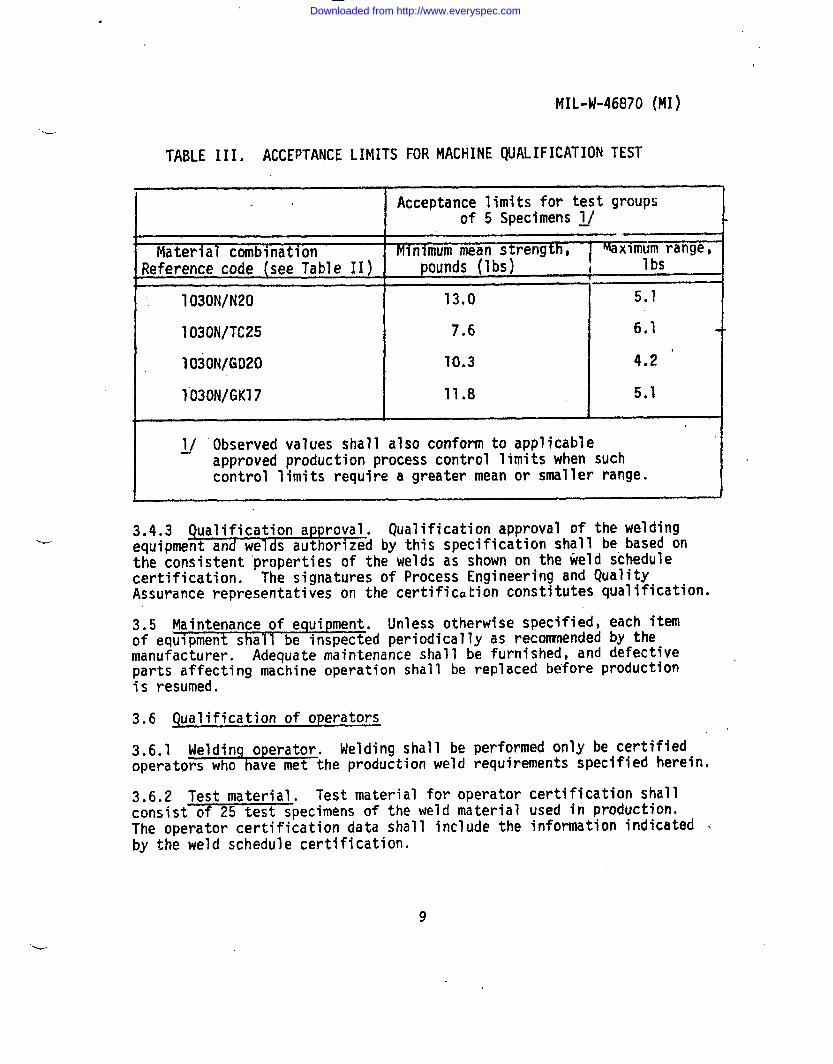
TABLE 111. ACCEPTANCE LIMITS FOR MACHINE QUALIFICATIONTEST
Acceptance limits for test groupsof 5 Specimens ~/
Material combination Mlnlmum mean strength, IMaxlmum range,
Reference code (see Table II) , pounds (Ibs) i 1bs
1030N/N20 13.0 5.1
1030N/TC25 7.6 6.1
1030N/GD20 10.3 4.2 “
lo30N/GK17 11.8 5.1I
~/ Observed values shall also conform to applicableapproved production process control limits when suchcontrol limits require a greater mean or smaller range.
3.4*3 Qualification approval. Qualificationapproval of the weldingequipment and welds authorized by this specification shall be based onthe consistent properties of the welds as shown on the weld schedulecertification. The signatures of Process Engineering and QualityAssurance representatives on the certificationconstitutes qualification.
3.5 Maintenance of equipment. Unless otherwise specified, each itemof equipment shall be inspected periodicallyas reconrnendedby themanufacturer. Adequate maintenance shall be furnished, and defectiveparts affecting machine operation shall be replaced before productionis resumed.
3.6 Qualification of operators
3.6.1 Weldinq operator. Welding shall be performed only be certifiedoperators who have met the productionweld requirements specified herein.
3.6.2 Test material. Test material for operator certification shallconsist of 25 test specimens of the weld material used in production.The operator certification data shall include the information indicated ~by the weld schedule certification,
9
Downloaded from http://www.everyspec.com
—— —
MIL-W- 46870 (Ml)
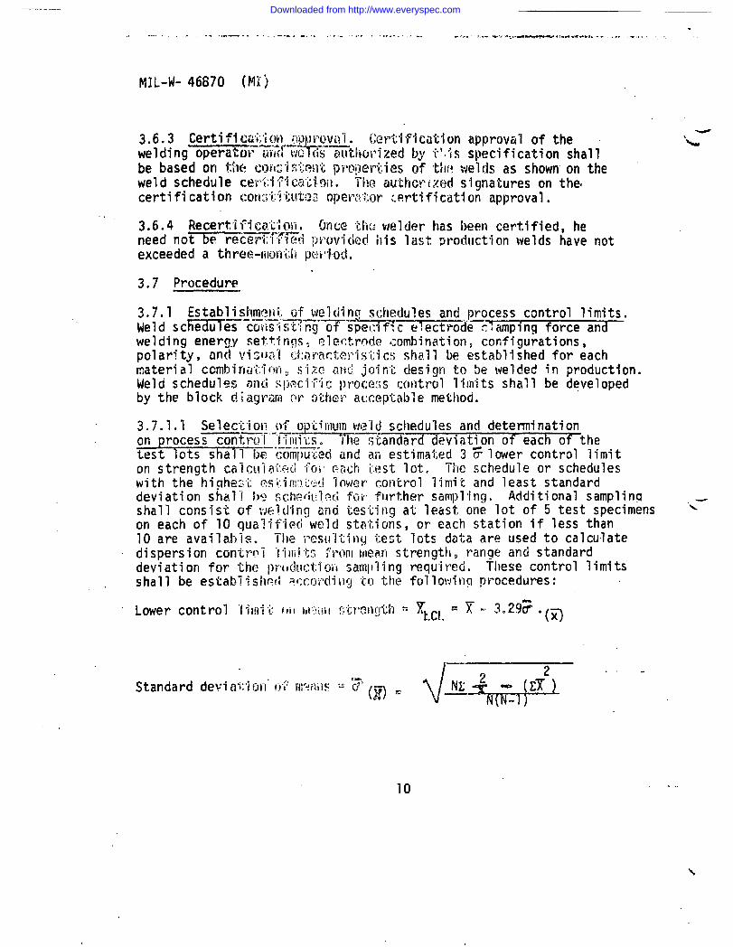
3.6.4 Recertif~<on, OncQ the welder has been certified, heneed no~ccr”(:i’rl~[i providcc!his last productionwelds have notexceeded a three-m]i.h p~i’id,
3.7 Procedure-
welding energ,yset.tinqsz..
‘electrodecombination cofif~gurationstpolarity, and vi~val d:2rIncteristicsshall be establishedfor eachmaterial ccmbirmtiotiosize at~djoint clesignto be welded in production.Weld schedules ~n{ispcci7ic proc~os control limits shall be developedby the block diagram or other acceptablemethod.
3.7.1.1 Selection of op’t~mumweld schedules and determinationon procesET6TtE’F5T--’lTiilitso The st~ard deviation of each of thetest lots shall be-~(;firtiikciand ah estimated 3 Flower control limiton strength caicu”izii:eti “foi’ (+dch i.estlot. lle schedule or scheduleswith the highe~i m;:.im:),Ll:!dlower control limit and least standarddeviation shall bQ sch~~iul.edfur flirt,hersampllng. Additional samplinq .+shall consist of welding ana testing at least one lot of 5 test specimens “\on each of 10 qualified weld stationsp or each station if less than10 are available. The ;ww’iting test lots data are used to calculatedispersion control “!~m~tr,from mean strength~ ran~e and standarddeviation for the pr(~(
.
- MIL-W- 46870 (MI)
Upper control limit on range = R,,e,= 4.87 3
Where N =
.x=
Range =
ubl-
Number of test groups of 5 samples each
Average pull strength of each 5-samples each
c= 5-sample qroupStandard deviation of each
.
Individual pull strength readings
Average of standard deviations
Difference between highest and lowest pull strengths(group of 5)
The factor 3.29 for lower control limit on mean strength above isbased on N (number of test groups) approachinginfinity. The controllimits shall be recalculated periodicallyusing the results of processcontrol tests until a minimum of 150 test groups are included. Process “-’control limits may be calculatedwith factors other than 3.29 whichreflect thesmaller sample size, as follows:
Number of test g“’oups Factor
Note:
3.65% 3*5560 3,46120 3.37”
w 3,29
Existing weld schedules. If certifiedweldschedules have been established for the samematerial combinationsand only minor differencesin finish or size prevail, as determinedby thecognizant Materials and Process activity,theexisting certifiedweld schedule may be used solong as the process control limits can be main- :tained.
11
Downloaded from http://www.everyspec.com

MIL-W-46870 (NI)
3.7.2 Surface preparation. Pr-and bus material shall be cleanforeign matter or contamination
or to welding, all component leadsand free from grease, dirt, and otherwhich could degrade the weld joint.
3.7.3 Conductor spacing and insulation. Intercon~ectingconductorsspaced less than 0.020 inch apart-l be covered with aninsulating sleeving conforming to-MIL-I-22129or AMS-3655. Unsupportedlengths over 0.75 inch in length shall be covered with an insulatingsleeving conforming to MIL-I-22129. Circuitry shall be fabricatedInaccordance with the engineering drawing.
3.7.4 Metal penetration and protrusion. The applied pressure ofthe weld electrodes forces each conductor to penetrate into the otherdisplacing a portion of the molten metal to the outer weld area. Themolten metal protrusion need not be fused to the surface of the twoconductors provided no voids appear within the weld area and penetrationconforms to the standards and requirementsspecified herein.Any protrusion that can be readily removed and any particles that couldcause a short shall be removed.
3.7.5 Production welding and inspection. Productionweldingshall be so accomplished as to obtain welds meeting or exceeding theminimum strength requirement as established in the-weld schedule.All test specimens selected for checking productionwelding shall berepresentative of the materials and configurationspecified in theweld schedule.
4. QUALITY ASSURANCE PROVISIONS
‘u-
4.1 Responsibility for inspection. Unless otherwise specified inthe contract or m’chase order, the supplier is responsiblefor the performance of all inspection requirementsas specifiedherein. Except as otherwise specified in the contract or order.The supplier may use his own or any other facilities suitable forthe performance of the inspection requirementsspecified herein,unless disapproved by the Government. The Government reservesthe right to perform any of the inspectionsset forth in thespecification where such inspectionsare deemed necessary toassure supplies and services conform to prescribed requirements.
4,1.1 Inspection system. The supplier shall prepare and maintain awritten detailed system of inspectionwhich will be utilized as a basisfor acceptance. The system shall include and identify inspectionstations necessary for proper maintenance of continued quality.
4.1.2 Qualified personnel. Qualified personnelwho have been dulycertified, shall be responsible for the control of machine settingsand all welding scl)edules.
12
Downloaded from http://www.everyspec.com

MIL-W-46870 (MI)
L- 4.2 Lot formation. A lot shall consist of all units welded atone.time, by the same processing facility, using the same batch ofmaterials in accordance with this specificationand submitted forinspection at one time.
4.3 Test methods and proceduresv
4.3.1 Test conditions. Unless otherwise specified herein,the following conditions shall be used to establish performancerequirements:
a. Temperature Room ambdent.(15”to 32 degrees C(60 to 90 deqrees F))
b. Altitude Facility ground ,,
c. Humidity Facility ambient up to 95percent relative humidity
4.3.2 Test specimen preparation
4.3.2,1 Machine qualification.specimens shall be “L” shaped as
Machine qualificationtestdepicted in Figure 3.
/
1-1/2 inch nominal 1-1/2 inch nominal
/
/“
Y‘~
90 degrees(approximate)
Note: Direction of testing indicatedby arrows
Figure 3. Design and method of test of “L” shaped specimens
w
13
Downloaded from http://www.everyspec.com

.._ ___ .
,..:,,,:
,.., ., MIL-W- 46870 (MI):.
..“.’..%,
f ...
i
4.3.2.2 Production and operator qualification. Productionoroperator quallflcatlon test specimens shall be of materials andconfigurations representing productionwelded ,joints.
}4.3.3 Tests
4.3.3.1 Joint strength
4.3.3.1.1 Testing specimen. Five test specimens prepared asspecified in 4.3.2 shall be tested for conformanceto 3.1.1 using atensile testing machine conforming to Federal Test Method StandardNo. 151, Method 211.1, at a maximum cross-head speed of 20 inchesper minute.
4.3.3.1.2 Testing production parts. Normally, productionweldedcomponents WI1l not be,tested. When deemed necessary by the authorizedinspector, a sample of actual production work shall be destructivelytested. If the sample is found to be unacceptable, productionshall be stopped and the previous 10 welds shall be re-examined. Ifa second sample destructively tested is acceptable and the previous..
‘.4 10 welds are visually acceptable,production may proceed withoutrejection of the entire lot.
e4.3.3.1.3 Testing frequency. The frequency of testing shall beas follows:
.,,,
&.
a. At the beginning of each production welding shift andevery 4 hours thereafter.
b. When the electrode or electrode angle is changed,
c. At the request of the authorized inspector.
Records of the test results shall be kept on file for examinationbythe authorized inspector.
4.3.3.2 Examination and inspection. Production welds shall bevisually examined using 10 to 5 power magnification for conformanceto the workmanship requirements in 3.1.2. Any component containingwelds with defects over and above the limits as defined herein shallbe re-examined for disposition by the cognizant engineering authority.
5, PREPARATION FOR DELIVERY (Not applicable)
“d-
14
Downloaded from http://www.everyspec.com
MIL W- 46870 (HI)
6. NOTES
-6.1 Intended use. The process in accordancewith this specificationjs intended to be used for welding micromodulecircuitrywherea high desity of interconnectingconductorsprecludes soldering.
6.2 Ordering data. Procurement documentsshould specify the followlng:
Title, Number and Date of this specification
6.3 Discoloration, A narrow band of discolorationmay be noted.Within the weld area on conductors. This discolorationis permissibleto the point of total discoloration of the weld area. Total disc~lorationis defined as a blackened or burned area. A light color of blue-greenis an acceptable condition.
6.4 Supersession data. This specificationincludes the requirementsof missile interim specification MIS-13851 dated 3 December 1970.
Custodian PreparingActivity:Army - MI Amy - MI
ProjectNo. THJM-A050
L
*.
15- . _ .. __ -_ ....._._.,_ ..—_______
w
...—----- .-—.—--...—-—. - .. . ----- -
Downloaded from http://www.everyspec.com

, .
:-
.’;
.
.,1,
.!
. .
. .:.
-
..
Downloaded from http://www.everyspec.com

INSTRUCTIONS: In a continuingefforttornalceourstandardizationdocumantahatter,theDoD ptid~ W formforx incubmitt@g commenta~d mrggaationafor irnprovamenta. AU UMreof mUary @anddtzation docunwmta are Mtd to provideauggeationE. l%ie form may be detached, folded along the lima indicated, taped along the 100EGedge (DO NOT ST&LE), aadrndled. In block 6, be m specific aEpoa$ible about particular problem areM such ae wording which requhd interpretation, wastoo rigid, rdrictive, 100U, ambiguoun, or wu incompatible, and give propoeed wording changes which would aihiata theproblenu. Enter in blpok 6 any remarks not related to a specific paragreph of the document. If block 7 b f’tiledout, anacknowledgement will be mailed to you within SO days to M you know that your comments were received and are betngconsidered.
NOTE: ‘I’M form may not be used to rqueat copjes of documents, nor to request wakers, deviations, or clarMicationof
speclfidion mquimmenta on ourmnt contracta, Commentesubmitted on tbia form do notcon8titu@orimp]yauthorization
to waive any portion of the referenced document(s) or to amend contractual requirement&
(Fold along ihti he)
(Foldolong thfc Ihu)
DEPARTMENT OF THE ARMY
111111IIMOPOSTANECS$S~RYtF MAILED
tN T HEUN17E08TAT8S
OFFICIAL BUSINESSPENALTY FOR PRIVATE USE $300 BUSINESS REPLYMAIL
‘FIFISTCLASS PERMIT NO. 12002 WASHINGTON 0. C&PO= AGE WILL BE PAID BY THE DEPARTMENT OF THE ARMY
ConunandexUS Army Missile CommandATTN: DRSMI-RSDSRedstone Arsenal, AL 35898
k,!.<
-. —.. .
Downloaded from http://www.everyspec.com

— ——
=..*-
STANDARDIZATION DOCUMENT IMPROVEMENT PROPOSAL
1.DOCUMENT NUMBER 2. OOCUMENT TITLE
1
k NAME 0PSU6Ml~lNG OROANlZAT10N 4, TYPE OF ORGANIZATION (Marh oru)
c1 VENDOR ‘N
c1 USER
I, AODHtZ8& (anw, City, 8tar8, 21P Codd
n MANUFACTURER
I D OTHER (8JUC//$): ,,
I
i, PROBLEM AREAS
b. Roaommendod Wording:
I
c. Roaorr/Rstlonalo for Rooomrrrondmlon:
B
4
, NAME OF SUBMITTER (k ad, $%0(, MI) - Optlond b. WORK”TE L6PHONE NUMBER (hseluti AtwCo*) - Optlorwl,
MAILING AOOREB2 (Strwt, City, 8tote, 21P Cod#) - Optbnd 8. OATE OF SUBMISSION (YYMMz)D)
--
I
DD &O:~R1426 PREVIOUS EDITION 190@20LETE,
Downloaded from http://www.everyspec.com