Embed Size (px)
Citation preview
TECH LIBRARY KAFB, NW1
• i 1 001,2130
Cf-
(HASA-Cfi-152027) FLEXIBLE CBXOGEKIC HEAT H77-29U51PIPE DEYELOPHJJBT PBOGBAH final Beport(Rockwell Intec national Corp., Donney,Calif.) U7 p BC A07/HF A01 CSC1 200 Unclas
G3/3U QU012
FLEXIBLE CRYOGENIC HEAT
PIPE DEVELOPMENT PROGRAM
Final Report
NASA CR 152027
July 1976 SD 77-AP-0088
\'---l
•A" ^_' "1
CONTRACT NAS2-8830
8
Rockwell International
SpaceDMston
https://ntrs.nasa.gov/search.jsp?R=19770022507 2018-07-09T11:27:51+00:00Z
s»»as&4
NASA CR 152027
a/.:J:;
-,-4
FLEXIBLE CRYOGENIC HEAT PIPE DEVELOPMENT PROGRAM
By J. P. Wright
Rockwell InternationalSpace Division
12214 Lakevood Blvd.Downey, CA 90241
4•i .--
f
July 1977
f1r<
Final Report
Contract No. NAS2-8830
^HI
Prepared For
Ames Research Center
National Aeronautics and Space Administration
Hoffett Field, California 94035
SD 77-AP-0088
tun ISi -USB??*®!
Rockwell InternationalSpacoDMaton
V•-i
'I •<•l f
FOREWORD
This report is submitted by the Space Division
of Rockwell International Corporation to the national
Aeronautics and Space Administration, Ames Research
Center in accordance with the requirements of Contract
NAS2-8830. The work was administered by the Project
Technology Branch of the Space Projects Division, with
Dr. Craig McCreight as Technical Monitor,
The program was performed under the direction of
J. P. Wright, Program Manager. Technical and Laboratory
assistance was provided by G. W. Gurr, Jr., C. D. Rosen,
D. E. Wilson, A. M. Lehtlnen, and T. T. Cafferty.
\1
I
-il-
HITRockwell InternationalSpace Division
IA1
CONTENTS
Section
1.0
2.0
3.0
4.0
5.0
Page
SUMMARY AND BACKGROUND 1
SUMMARY 1
BACKGROUND 2
SPECIFICATIONS AND REQUIREMENTS 5
DESIGN PAJIAMETERS AND TRADEOFFS 9
WORKING FLUID 9
CONTAINER DESIGN 11
WICK DESIGN 13
ANALYSIS AND DESIGN 17
PARAMETRIC ANALYSIS 17
SELF-PRIMING 17
TRANSPORT CAPABILITY -0
HEAT PIPE DESIGN SUMMARY 20
PARAMETRIC PERFORMANCE 23
EIGH POWER HEAT PIPE FABRICATION AND TEST 37
HEAT PIPE FABRICATION 37Flexible Container 37Primary Wick Fabrication and Testing 42Wick Standoffs (Bridges) 50Fill Tube and End Cap 50Final Assembly 50
BAKEOUT AND FILLING 52Bakeout 52Filling 52
TEST PROGRAM 52Methane Tests 53Gas Analysis Tests .. ...... 61Ammonia Tests • 63Visual Examination €6-
EVALUATION -69
i*
.' -t_._t.' «i «
.,....,f - . . \..__= .iVflf ., ,, .,, j
Rockwell InternationalSpace Division
CONTENTS (CONTINUED)
Section
6.0
7.0
8.0
Page
LOW TEMPERATURE HEAT PIPE FABRICATION AND TEST 71
HEAT PIPE FABRICATION 71Flexible Container 71Primary Wick Fabrication and Testing 75Wick Standoffs (Bridges) 79Fill Tube and End Cap 79Final Assembly 79
BAKEODT AND FILLING 82Bakeout. 82Filling 82
TEST PROGRAM 82
FLEXURAL CYCLE TESTS 91
TEST SET-UP 91
TARE TESTS 93
FLEX TESTS 93
EVALUATION 93
CONCLUSIONS AND RECOMMENDATIONS 99
GENERAL 99
FLEXIBILITY 99
PERFORMANCE 100
RECOMMENDATIONS *. .101
REFERENCES 103
APPENDIX A .
WICKPER PROGRAM UTILIZATION MANUAL
APPENDIX B . .'
PARAMETRIC PERFORMANCE PREDICTIONS
Rockwef I InternationalSpace DMskn
LIST OP ILLUSTRATIONS
Figure2-1 Flexible Heat Pipe Layout 8
3-1 Liquid Transport Factor Vs. Temperature 10
3-2 Wicking Height Factor Vs. Temperature 10
3-3 Vapor Pressure Vs. Temperature 10
3-4 Thermal Conductivity Vs. Temperature ... 10
3-5 Flexible Composite Wick Design 15
4-1 Wick Permeability Test Set-Up 19
4-2 Heat Transport Summary Based on Theoretical Nick Permeability 24
4-3 Heat Transport Summary Rased on Measured Wick Permeability. . 26
4-4 Theoretical Performance of High Power Flexible Heat Pipe in"0-g" (methane) 28
4-5 Theoretical Performance of High Power Flexible Heat Pipe in"0-g" (ethane) 29
4-6 Theoretical Performance of Low Temperature Flexible Heac Pipein "0-g" (oxygen) 30
4-7 Theoretical Performance of Low Temperature Flexible Heat Pipein "0-g" (nitrogen) 31
4-8 Heat Transport Capability of High Power Flexible Heac Pipe vs.Elevation (methane) 32
4-9 Heat Transport Capability of High Power Flexible Heat Pipe vs.Elevation (ethane) 33
4*40 Heat Transport Capability of Low Temperature Flexible MeatPipe vs. Elevation (oxygen) ..... 34
4-11 Heat Transport Capability of Low Temperature Flexible HeatPipe vs. Elevation (nitrogen) ..... 34
5-1 High Power Heat Pipe Design Details 39-40
5-2 Heat Pipe Fabrication Sequence 41
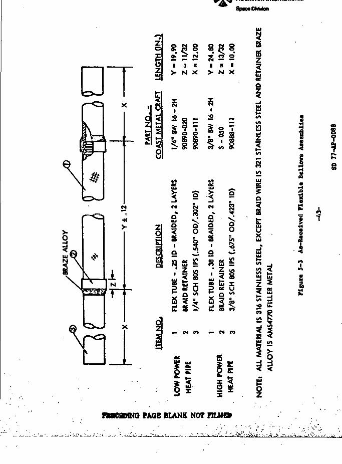
5-3 As Received Flexible Bellows Assemblies 43
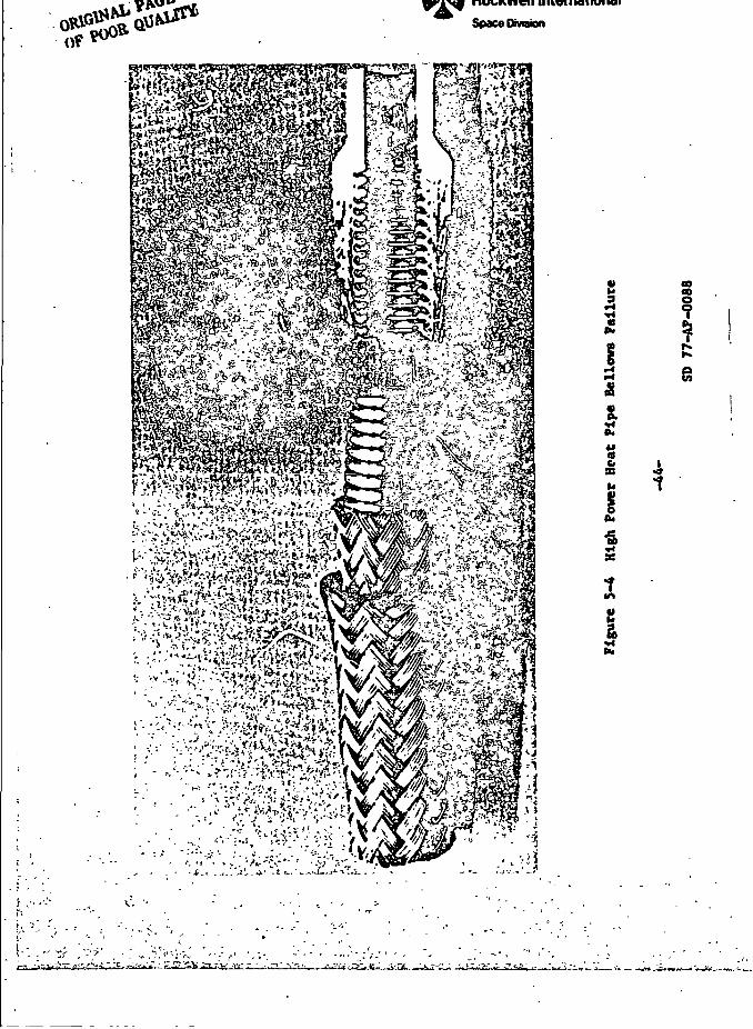
5-4 High Power Pipe Bellows Failure 44
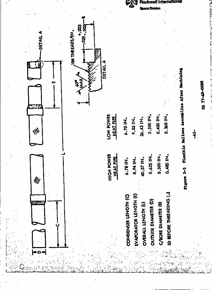
5-5 Flexible Bellows Assemblies After Machining 45
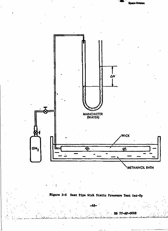
5-6 Heat Pipe Wick Static Pressure Test Set-Up ... 46
5-7 Flow Permeability Test Results with High Power Heat Pipe Wick 48
5-8 High Power Heat Pipe Components 51
y' n•i.
i.
i i
• •?' M
•"»?-I • • I I I :v4 I
^-H -->s. • .^--"H*- , T- -,-. (<tt\iMij -. 1 .1—;.--,-_. i
Rockwell InternationalSpaceDMston
LIST OF ILLUSTRATIONS (CONTINUED)
Figure
5-9
5-10
5-11
5-12
5-13
5-14
5-15
5-16
5-17
5-18
5-19
6-16-2
6-3
6-4
6-5
6-6
6-7
6-8
6-9
6-10
7-1
7-2
7-3
7-4
High Power Heat Pipe Heater and Thermocouple Locations . .
Schematic of Capillary Interface Between Screen Wick and
Flow Permeability Test Data, Low Temperature Heat Pipe Uicl
Low Temperature Heat Pipe and Pressure Reservoir Assembly
Heater and Thermocouple Locations for Low Temperature Heat
^ ^ »»f' .— __—^ ^
Page
54
55
56
57
58
59
61
66
656868
. 73-74
77
i. 78
8183
Pipe 84
85
87
89
92
> 94
95
97
/
I
Rockwell InternationalSpawDMston
(i
Number
2-1
2-2
2-3
3-1
4-1
4-2
4-3
5-1
5-2
5-3
7-1
TABLES
Specified Heat Transport and Static Height
Specifications for Flexible Cryogenic Heat Pipes
Heat Transport and Static Height for Design Temperature Ranges
Film Coefficients for Oxygen and Methane '
Permeability Test Results ........ ...
High Power Heat Pipe Design Summary .
Low Temperature Heat Pipe Design Summary ..........
High Power Heat Pipe Burnout Data
Gas Chromatography Results ...........
Burnout Test Results
Results of Cryogenic Heat Pipe Cyclic Testing
Page
678
12
19
21
22
58
62
66
96
„<,/
-•'T. --
^ 7.»-
:.|-'
L ™,_L . _J_ i v' l
Rockwell InternationalSpac«OMston
/7
1.0 SUMMARY AND BACKGROUND ,J
SUMMARY
This report summarizes the results of Contract NAS2-8830, "Development
of a Flexible Cryogenic Heat Pipe Program." The program was Initiated in
July 1975 and was completed in July 1977. The program was an analytical
and experimental technology development effort to develop the technology and
experience necessary for successful application of high performance flexible
cryogenic heat pipes. Two pipes were designed and fabricated for testing
and evaluation. One was designed for operation in the 100-200 K temperature
range with maximum heat transport as a primary design goal; the other was
designed for operation in the 15 - 100 K tejsperature range with maximum
flexibility as a design goal.
Parametric performance and design trade-off studies were performed to
determine the optimum geometry and materials for the container and wicking
systems. The 100 - 200 K pipe was designed for operation with methane and
ethane, and was optimized for methane in the range 110 - WOK. The 15 - 100 K
pipe was designed for operation with nitrogen and oxygen, and was optimized
for oxygen in the range 75 - 90 K.
The selected wick design was a multi-wrap composite, consisting of a
spirally-wrapped coarse mesh screen encapsulated by a fine mesh outer wrap.
Screw thread type V-grooves were machined Into the evaporator and condenser
walls for circumferential liquid distribution. A braided flexible stainless
steel bellows assembly was used for the flexible section. The container was
designed for a pressure safety factor greater than four, with an ultimate
design burst pressure of 10.3 x 10⁷ Pa.
The high power (100 - 200 K) heat pipe was tested with methane at 100 -
WOK, and test data indicated only partial priming with a performance limit
of less than 50 percent of theoretical. A series of tests were conducted
with ammonia at '280 K to determine the performance under varying fluid
charge and test conditions. The low temperature heat pipe was tested with
oxygen at 85 - 95'K and with methanol at 295 - 3158K. Performance of the
Rockwell InternationalSpace Division
low temperature heat pipe was above the specification (6 - 8w vs. 4.5w) but i • -.
was below theoretical predictions. Results of the completed testing are ;
presented and possible performance limitation mechanisms are discussed in •»
sections 5.0 and 6.0. The lower-than-expected performance was felt to beV
due to small traces of non-condensible gases which prevented the composite
wick from priming. Additional investigation and parametric testing is j;
recommended since all cryogenic composite wicks are subject to the sane
potential degradation. j
BACKGROUND
As performance and lifetime requirements for future spacecraft systems
and experiments become more stringent, the need and demand for reliable and
efficient passive thermal control systems becomes more critical. This has |
been evidenced by the increasing number of spacecraft systems utilizing '
ambient temperature heat pipes over the past five years. More recently, the
advantages of heat pipes for thermal control have been realized on systems i>
operating at cryogenic temperatures. The RM-20B radiator (Reference 1) was- i
the first application of cryogenic heat pipes into a space qualified '
thermal control system. I '
Preliminary design studies of futara DOD and NASA programs and experiments }i
indicate increasing applications of cryogenic heat pipes. In many cases, i
flexibility is required because of co-planar ground test requirements or to I 4
facilitate on-orbit deployment, orientation or scanning. Although'the tech- { ]
nology of rigid cryogenic heat pipes is reasonably'well established down to ] |
80°K, flexible cryogenic heat pipe development to date has been limited. A , |
flexible cryogenic heat pipe with methane as the working fluid was tested •' j
at 110'K during 1974 (Reference 2). Although test data indicated that ', \
the concept was feasible, a highly flexible cryogenic heat pipe has yet ; • !
to be developed and qualified. Below 80°K, little or no data exists although ,
there appear to be applications with requirements as low as 20°K or lower.
In addition to providing a flexible heat transfer link for deployable
or moving spacecraft systems, flexible heat pipes offer several advantages
over rigid heat pipes in many applications. A flexible heat pipe:
-*- . ' *:
RockweU internationalSpace OMtion
(1) Facilitates fabrication by eliminating the need for
accurate bends and alignment tolerances. Flexibility
also facilitates Installation and allows more accurate
alignment of the heat pipe at critical interfaces.
(2) Minimises or eliminates stresses in a system due to
differential thermal .contraction between the heat pipe
and the system aa the system is cooled to operating
temperature levels. This feature is critical in
applications where heat pipes interface with optical
or infrared sensors which require extremely accurate
alignment tolerances.
(3) Allows meaningful ground testing of heat pipes which
require multiple plane bends in the installed
configuration.
Potential NASA applications include the Shuttle Infrared Telescope
facility, the NASA/JPL Gamma Ray Spectrometer, and the NASA/JSC Super-
conducting Magnetic Spectrometer. The use of flexible heat pipes to thermally
link a detector or sensor with a cryostat or radiator provides needed
flexibility of detector location, whereas in many conventional systems, the
cryostat or radiator location is constrained by pointing requirements for
the detector. This flexibility of location could result in reduced space
and weight, lower dynamic loads, and lower environmental heat loads.
Cryostats could also be better located to minimize center-of-gravity changes
as the cryogen evaporates.
The two flexible pipes reported here were each chosen to be represent-
ative of a particular class of applications. The 100 - 200 K high power heat
pipe is of the type useful for deployable radiators, where large distances
or heat loads and a small number of flexures are generally required. The
low temperature, maximized-flexibility pipe is applicable to cooling of
moveable cryogenically-cooled detectors.
•{ •< ....—ry -nr—IT- ,—.-_,,„, I I I .__.!-..- -._.—.—j.-.1.--.^.^- •Vir
Rockwell InternationalSpace Division
2.0 SPECIFICATIONS AND REQUIREMENTS
The high power heat pipe was to be designed for a specific operating *
temperature in the tange of 100-200°K, with che heat transport capability
as great as possible. The low tc-nperature heat pipe was to be designed for
a specific operating temperature in the range of 15-100°K. The heat pipes
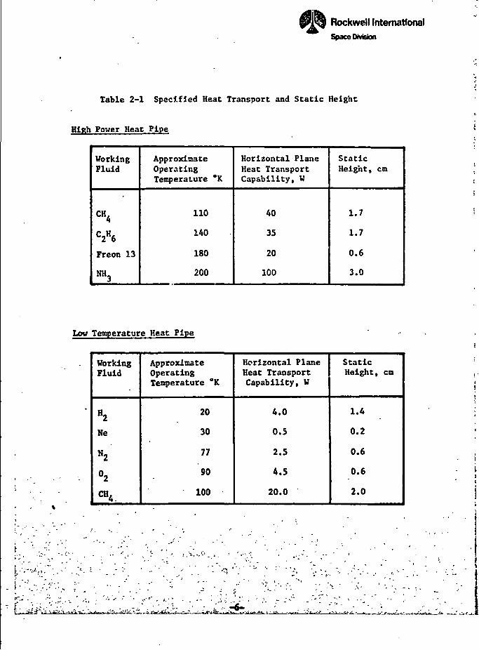
should meet or exceed the heat transport and static height values shown in
Table 2-1 for various fluids. As discussed in Reference 3, the specified
heat transport and static height values for neon may not be achievable
with a single design for all of the fluids because of its poor surface
tension.
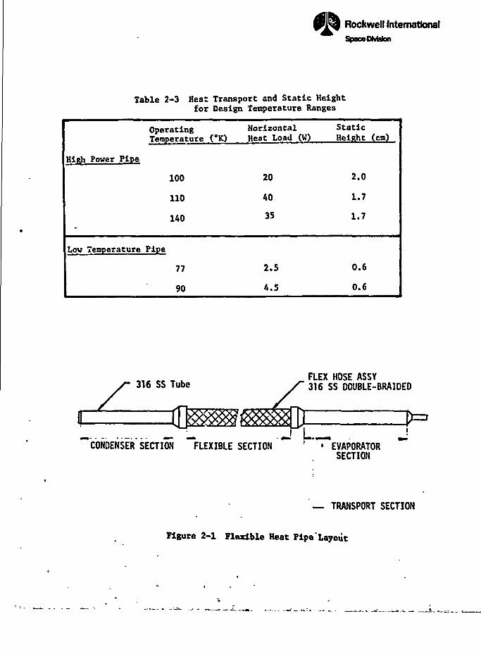
The high power heat pipe was designed and optimized for operation with
methane at 100 to 140°K. The low temperature heat pipe was designed and
optimized for operation with oxygen at 77 to 90°K. The heat transport and •*6
static height corresponding to these temperature ranges for the high power
and low temperature heat pipe are shown in Table 2-3.•i
In addition to the above specifications, the primary wick must be .;,
capable of self-priming against an adverse elevation (0.2 cm was selected for >.
design purposes). The heat pipe must also be designed to withstand a burst ~\
pressure of four times the internal pressure of a fully charged pipe at the 3
maximum service temperature (315°K). A schematic of a flexible heat pipe -,'•
is shown in Figure 2-1 for reference.
fflBGIMN10 FACE BLANK MOT FHJffifr
-5-
IRockwell InternationalSpace Division
Table 2-1 Specified Heat Transport and Static Height
High Power Heat Pipe
WorkingFluid
CH
C2«6
Freon 13
NH3
ApproximateOperatingTemperature *K
110
140
180
200
Horizontal PlaneHeat TransportCapability, W
40
35
20
100
StaticHeight, cm
1.7
1.7
0.6
3.0
Low Temperature Heat Pipe
I -p"..,s
-. c- •-
WorkingFluid
H2
Ne
*2
°2
CH4
ApproximateOperatingTemperature °K
20
30
77
90
100
Horizontal PlaneHeat TransportCapability, W
4.0
0.5
2.5
4.5
20.0
StaticHeight, cm
1.4
0.2
0.6
0.6
2.0
'L.^^k % - *^t*t^H f,^' . '• ' *•,,•
flRIRB D^ l .. !! l«».&***AMA*ftal ' J
SpaoeOivision
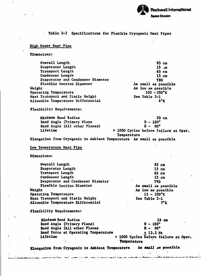
Table 2-2 Specifications for Flexible Cryogenic lieat Pipes
High Power Hear Pipe
Dimensions:
Overall LengthEvaporator LengthTransport LengthCondenser LengthEvaporator and Condenser DiameterFlexible Section Diameter
WeightOperating TemperatureHeat Transport and Static HeightAllowable Temperature Differential
Flexibility Requirements:
95 cm15 -n65 cm15 cmTBD
As small as possibleAs low as possible
100 -200°KSee Table 2-1
Minimum Bend RadiusBend Angle (Primary PlaneBend Angle (All other Planes)Lifetime
20 cm0 - 180°0 - 90°
> 1000 Cycles before failure at Oper.Temperature
Elongation from Cryogenic to Ambient Temperature As small as possible
Low Temperature Heat Pipe
Dimensions:
Overall LengthEvaporator LengthTransport LengthCondenser LengthEvaporator and Condenser DiameterFlexible Section Diameter
WeightOperating TemperatureHeat Transport and Static HeightAllowable Temperature Differential
Flexibility Requirements:
Minimum Bend RadiusBead Angle (Primary Plane)Bend Angle (All other PlanesBend Force at Operating TemperatureLifetime
Elongation from Cryogenic to Ambient Temperature
95 cm15 cm65 cm15 cmTBD
As small as possibleAs low as possible
15 - 100°KSee Table 2-1
3°K
14 cm0 - 180°0 - 90°< 13.3 Ht
> 1000 Cycles TJefore failure at Oper.Temperature
As small as possible
A
1!
•II
I
•'.'." *''.?*$
Rockwell InternationalSpace Division
nTable 2-3 Heat Transport and Static Height
for Design Temperature Ranges
Operating HorizontalTemperature <°K) Heat Load (W)
High Power Pipe
.
Low Temperature
100
110
140
Pipe
77
90
20
AO
35
2.5
4.5
StaticHeight (cm)
2.0
1.7
1.7
0.6
0.6
3
'!• y
316 SS Tube
CONDENSER SECTION FLEXIBLE SECTION
FLEX HOSE ASSY316 SS DOUBLE-BRAIDED
I .' • EVAPORATOR
SECTION
— TRANSPORT SECTION
Figure 2-1 Flexible Heat Pipe'Layout
Eiiiiirini_iizi ..:
Rockwell InternationalSpace Division
i/f
'
3.0 DESIGN PARAMETERS AND TRADEOFFS
Although design procedures vary with application, the heat pipe design
methodology generally consists of selecting a working fluid on the basis of• j!
its physical and thermodynamic properties in the required operating temper- .5 '
ature range, and designing an envelope which will meet the specified •
performance and pressure containment requirements. Optimization generally '
involves either maximizing the transport capability within a fixed physical i
envelope, or minimizing the size and/or weight for a specified transport and j
conductance requirement. >
The requirement for flexibility, particularly with cryogenic heat pipes,i
imposes a number of additional design considerations on the wick and
container. The following paragraphs discuss the various factors as they 3
relate to the optimization of a flexible cryogenic heat pipe. b\
WORKING FLUID *t
In general, the best working fluid is one which is compatible with *
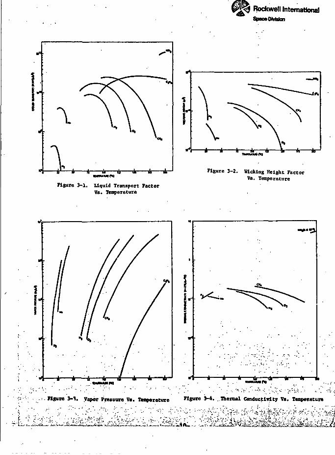
applicable container materials and whose liquid transport factor (N.j, wlcklng *
height factor (H), and thermal conductivity (k) are the highest. In addition, ""••it is desirable to have the fluid's normal boiling point below the operating '::
range in order to avoid excessive vapor losses. Furthermore, maximum
flexibility and minimum container strength and weight are realized if the "}
fluid has a low critical pressure and a high critical temperature. Pertinent *
fluid properties for the specified heat pipe fluids are shown as a function x '
of temperature In Figures 3-1 through 3-4.
In the cryogenic regime, especially at the low end, there are a limited
number of suitable fluids, and each has a relatively narrow operating range.
For example, helium, hydrogen, and neon are probably the only fluids suited
for operation in the 0 to 40°K range. Meaningful thermal tests with helium
in the 0 to 8°K range art questionable. Hydrogen has adequate transport
properties in the 15 to 30°K range but poses safety requirements. Neon has a
relatively high liquid density and a very low surface tension which result "
i •i.jT.. »^«.i..yAfnmen»Bm_i. i .u. .ni i,m«|».•iniguigw.iii» • nauj j.
raws!tsror ^ ...
• Rockwell InternationalSpeceOMatan
Figure 3-1. Liquid Transport FactorVs. Temperature
Figure 3-2. Wlcklng Height FactorVs. Temperature
-4—-4 * 6' it ik * 1
*".""'." ;.-:' f1*"1* 3~1« Vapor Pressure Vs. Teaperature Figure 3-4. Thermal Conductivity Ve. Temperature
-tzli ifi ^.-;•£•
"V'S^Krf iwr — »•/. •• ••••lUj uMMttMHiiC
Rockwell InternationalSpace DMsfcn
in an extremely low vicking height factor in Che 3" to 40°K range. As aresult, 1-g testing with this fluid is extremely difficult even with
optimized wick designs. It should also be pointed out that between the
critical temperature' of neon (44.5°K) and the triple point of fluorine (54 DK)
no two-phase fluids exist. The 40-60°K range is therefore Impractical for
heat pipe operation.
Oxygen and nitrogen are the most suitable for the low temperature pipe.
Fluorine was discounted on the basis of safety and handling; argon, on the
other hand, has comparable transport properties, but its melting point is higher
than either oxygen or nitrogen (84.2°K). Oxygen was selected as the working
fluid for the low temperature pipe.
In the 100 to 200°K range, fluids have a broader operating range and
their perofrmance is generally better. Methane and ethane have the highest
heat transport and wicklng height factors (with the exception of ammonia
whose melting point is slightly below 200°K) . Several of the Freons (e.g.
F-13, F-14, and F-21) are also useable but their wicking height factors are
approximately 1/2 that of either methane or ethane in the respective operating
ranges. Consequently, less permeable wicks are required to satisfy the self-
priming criterion and this in turn results in substantially lower transport.
Methane was selected as the wicking fluid for the high power heat pipe.
CONTAINER DESIGN
Design considerations for the container include flexibility at operating
temperatures, pressure containment at the maximum service temperature, flex-
ural fatigue after repeated cycling, elongation, compatibility with the work-
ing fluid, and machinability and weldabillty. The thermal conductivity of
the container wall is an important consideration in the evaporator and
condenser. The material properties corresponding to pressure containment,
elongation and flexibility are yield strength, thermal coefficient of
expansion, and ductility, respectively. Various materials and designs for
the flexible container were evaluated. The selected design is a 316 stainless
steel braided flexible bellows assembly with a 316 stainless steel tube
brazed at either end for the evaporator and condenser sections. In addition
to satisfying requirements for flexibility, compatibility, containment, etc.,
-11- «—<*-.. u«._
T T I I I'hit .1 II»M»»>4«
Rockwell InternationalSpace Division
this type of flexible hose is readily available as an "off the shelf" item.
The inside diameter (ID) of the container is determined by flexibility,
thermal conductance, containment and transport requirements. Nominal 0.953 cm
(3/8 in) and 0.635 cm (1/4 in) flexible hose sizes were selected for the high
power and low temperature pipes, respectively, on the basis of a preliminary
transport analysis and flexlblity requirements.
Evaporator and condenser I.D.'s must also be consistent with thermal
conductance requirements. Available literature was reviewed to establish
film coefficients for the methane and oxygen pipes (References 2, 4, 5 and 6).
There are limited data for both fluids and in fact oxygen has been tested !
only in an axial grooved heat pipe (Ref. 4). Since axial groove film
coefficients are generally lower than those for screw thread secondary
wicks, the axial groove values were used to predict conservative conductances '
for the flexible pipe. A summary of film coefficients available in the
literature for methane and oxygen is presented in Table 3-1.
Table 3-1 Film Coefficients for Oxygen and Methane
Fluid
Oxygen
Methane
Temperature•K
100
100-130
100-120
125
120
Wick Design
Axial groove
Axial groove
Axial groove
Spiral artery/screw threadgrooves
Multiple artery/screw threadgrooves
Evapora(W/m2-°C)
2900
1730
2300
1700
:or(BTU/hr-ft2-DF)
500
300
400
300
Condense(W/m2-°C)
4900
6100
3300
-
r(BTU/hr-ft'-'F)
865
1070
570
-
Average3060 W/m2-C (530 BTU/hr-f t2-'F)
The relatively low heat loads specified for the low temperature pipe
allow the 3*C design goal to be satisfied with a tube ID less than 0.635 cm
(1/4 in), and the specified 15-cm evaporator and condenser lengths. A
0.98 cm ID was selected for the evaporator and condenser sections to
accommodate the oxygen pressure without using a reservoir.
-12-
Rockwell InternationalSpace MvWon
It was necessary to increase the evaporator length of the high power pipe
to 20.3 cm in order to limit its temperature drop to 3°C. Evaporator and
condenser IDs could have been increased but these sections would become
unnecessarily bulky and would impact the self-priming ability of the wick.
WICK DESIGN
The various factors that affect the wick design include self-priming
and transport requirements, flexibility, and materials compatibility. Screen
is readily available in 316 stainless which is also the container metal.
Optimum flexibility in a screen wick is obtained by orienting the crossmembers
or fibers on a bias relative to the longitudinal axis of the wick to avoid
normal compression of the fibers in bendl-~. With the square mesh screens
that are commonly used to fabricate conventional wicks, bias angles between
30 and 60 degrees provide the greatest flexibility. In addition this also
provides the axial pliability needed for expansion and contraction. Maximum
flexure in all directions requires a wick which has a circular or annular
cross-section and is concentric with the container. The cross-section should
be as small aa possible, consistent with transport and wicking height
requirements.
Examination of the transport and static height specifications indicates
that composite wick designs are required. Axially graded wicks are a possible
alternative but they were not sufficiently developed to be considered for
this application. A variety of composite wick designs have been tested.
These Include the pedestal artery, multiple central artery, spiral and
tunnel artery, and multi-layer slab. The slab used in the feedback controlled
heat pipe for the ATFE (Ref. 7) has demonstrated reliable zero-g start-upwith a non-condensible gas present. Since some amount of gas generation must
be expected over the life of a heat pipe, a multiwrap design with a circular
cross-section was selected as the baseline. This wick consists of a
circular core of coarse screen which is encapsulated by fine m».sh screen at
the loner and outer surfaces and at the ends. The coarse mesh provides high
permeability for liquid flow while the outer mesh gives high capillary
pumping. Spiral artery designs which utilize annular flow passages
established by spacer wires between layers of fine mesh screen were considered
•4
-13-
t t'-7fJS^K»K^aa<xmttmn3>^!feisafe=fstn3K^<ut
Rockwell InternationalSpace DMston
in Che analysis as an alternate. Each design includes a centrally-locatedtunnel with both evaporator and condenser ends sealed with the fine mesh
screen. This was done to permit operation with a Clapeyron-primed tunnel
artery. No attempt was made to optimize with regard to the tunnel
diameter.
Cross-sections of the two wick types are shown in Fig. 3-5. Four
equally spaced interconnecting screen bridges are used in the evaporator and
condenser sections to interface the centrally located primary wick with the
circumferential screw thread grooves on the container wall. The bridges
consist of two wraps of the fine mesh screen used in the primary wick.
.-.I
-14-
^1 . -^ r .H.^l'""- ^.V I','."•'.'•. -V
Rockwell International
COARSE MESH
TUNNEL
FINE MESH
ORCUMFERENTIAL GROOVE
INTERCONNEaiNG BRIDGE
a) Multiwrap Wick Configuration
SPAQR WIRES
. b) Spiral Artery Hick Configuration
Figure 3-5 Fltrlble Conpoaite Wick Design*
-15-
I ...... I I U I
PAtiS BLANK W« FBJU*
Rockwell InternationalSpmOMakm
4.0 ANALYSIS AND DESIGN
PARAMETRIC ANALYSIS
A parametric analysis was conducted to establish wick properties and
cross-sections which yield optimized transport capability consistent with
the previously specified design and performance criteria.
SELF-PRIMING
Once a container ID has been chosen, it is necessary to establish the
wick parameters which satisfy the "1-g" self-priming requirement. The
hydrostatic priming head fa ) associated with priming a concentric wick of
diameter D which is supported by bridges of diameter D and has an adverseW a
elevation of 0.20-cm is given by
HSP " DW B °*2° (cm)
The corresponding pumping radius rCD required for self-priming isCD
spSP 8o HSP
(cm) (4-2)
Where a is the surface tension, p. the liquid density and g the gravitational
constant. The self-priming radius was determined at 100*K and 140°K f:iv
oxygen and methane, respectively, since this will guarantee priming over the
temperature range specified for each of these fluids. Also, in order to
Initiate the analysis it was necessary to estimate the diameters of the wick
and bridges. This was done by assuming that the liquid and vapor flow areas
are equal. Hence for a given container ID, values for D and D_ are readily
determined. In general this assumption proved slightly conservative. Since
transport requirements were easily satisfied, no Iteration between self-
priming and transport capability was performed.
In the case of the multi- wrap design, the corresponding mesh sice of the
coarse screen can be determined as (Reference 8)
J>*
H
?
-17-
\ /n ,—n—l._r_I_T
Rockwell InternationalSpaotDMstan V
<!
Once the mesh size has been established, the coarse screen can be completely
specified by defining its wire diameter d . This consists of maximizing
the permeability within fabrication limits. The permeability of screens is
determined from the Kozeny Equation (Reference 8).
where d.. is the wire diameter and
Althout it is not explicit in the proceeding equations, for a given mesh
size, the porosity and correspondingly the permeability increase as the wire
diameter is decreased. However, experience gained in fabricating development
samples of the wick for the low temperature pipe Indicated that screens with
wire diameters less than 0.17-mm are very sensitive to compression and. tend
to deforn readily.
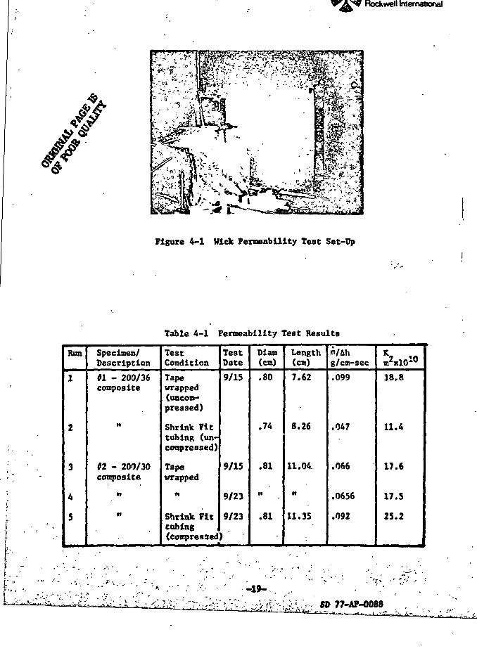
Flow permeability tests were rund on short spirally wrapped wick samples
with various mesh sizes and wire diameters. The test set up is shown in
Figure 4-1. Hater was allowed to flow across the test specimen from a
constant pressure head reserve 'r. The differential pressure scross the
specimen was measured with an open V-tube manometer. The mass flow rate was
measured by collecting the efflux in a container and weighing it after a
measured time interval. Test results for several wick samples are shown in
Table 4-1.
Wire diameters of 0.33 and 0.14-mm were selected for the high power and
lew temperature heat pipes, respectively, on the basis of adequate permeability,
and availability. For the spiral artery, the self-priming requirement dictates
-18-
j
j
Space DivisionRockwell International
//#^
Figure 4-1 Wick Permeability Test Set-Up
g
1
Table 4-1 Permeability Test Results
Run
1
2
3
4
5
Specimen/Description
01 - 200/36composite
ti
02 - 200/30composite
n
n
TestCondition
Tapewrapped(uncom-pressed)
Shrink Tittubing (un-compressed)
Tapewrapped
n
Shrink Fttcubing j
TestDate
9/15
9/15
9/23
9/23
(compressed)
Diam(cm)
.80
.74
.81
n
.81
Length(cm)
7.62
8.26
11.04.
n
11.35
m/Ahg/cm-sec
.099
.047
.066
.0656
.092
mW
18.8
11.4
17.6
17.5
25.2
^J
*-.A|I
. 'n •' *•' ;
SO 77-AP-0088
1ZZT"•f"* TV* v*f*"t rr -v LI'1*Rockwell International
Space Division
the diameter of the spacer wires which in turn determines the wick's
permeability.
TRANSPORT CAPABILITY
A computer program was written to determine the heat transport capability
of the wicking system. The program models the secondary wick standoffs
(bridges) and the circumferential screw threads as well as the primary axial
wick. The program, called WICKPER, is described in Appendix A. Sample
results are presented in Appendix B.
Once the wick parameters have been determined, the WICKPER program is
used to establish the optimum wick area which gives the maximum transport
capability at a specified temperature. The program calculates transport
capability considering laminar liquid losses through the primary wick, the
evaporator and condenser bridges, and the evaporator's screw thread grooves.
Laminar or turbulent vapor flows are also taken into account. In order to
avoid excessive vapor losses, which are less predictable than the laminar
liquid flow, acceptable wick areas were limited to those which resulted in
values of the friction parameter (F) being larger than 0.70, where
F - tf (4-6)
This criterion was only applied in the wick optimization with the tunnel
unprimed. Once the wick had been determined its performance with a primed
tunnel was then predicted and generally the corresponding values of F were
less then 0.70. The optimum wick area was determined at the low end of the
specified temperature range (i.e., 75°K for oxygen, 100°K for methane), since
the lower the temperature the more dominant the vapor losses.
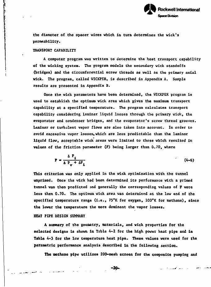
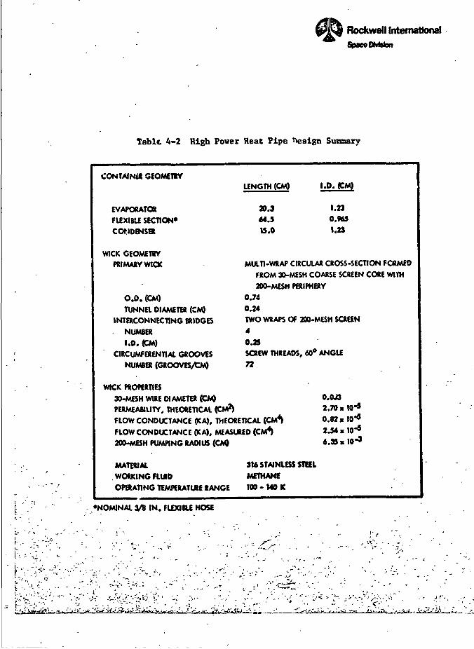
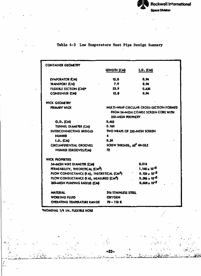
HEAT PIPE DESIGN SUMMARY
A summary of the geometry, materials, and wick properties for the
selected designs is shown in Table 4-2 for the high power heat pipe and in
Table 4-3 for the lew temperature heat pipe. These values were used for the
parametric performance analysis described in the following section.
The methane pipe utilizes 200-tnesh screen for the composite pumping and
-20-
L ' '•• '& \' ' v *
- /'. -r "•
. . . . , ,
Rockwell InternationalSpace DMsfen
Table 4-2 High Power Heat Pipe Design Summary
CONTAIN** GEOMETRY
EVAPORATOR
FUXIBLE SECTION*
CONDENSER
WICK GEOMETRY
PRIMARY WICK
0.0. (CM)
TUNNEl DIAMETER (CM)
INTERCONNECTING BRIDGES
NUMBER
1.0. (CM)
CIRCUMFERENTIAL GROOVES
NUMBER (GROOVES/CM)
LENGTH (CM)
30.3
64.5
15.0
1.23
O.MS
1.23
MULTI-WRAP CIRCULAR CROSS-SECTION FORMED
FROM 30-MESH COARSE SCREEN CORE WITH
200-MESH PERIPHERY
0.74
0.24TWO WRAPS OF 200-MESH SCREEN
4
0.25SCREW THREADS, 60° ANGLE
72
WICK PROPERTIES
30-MESH WIRE DIAMETER (CM) O.OJ3
PERMEABILITY, THEORETICAL (CM2) 2.70 x W*
FLOW CONDUCTANCE (KA), THEORETICAL (CM4) 0.82 x
FLOW CONDUCTANCE (KA), MEASURED (CM4) 2.54 x
200-MESH PUMPING RADIUS (CM) 4.35 » ID"9
MATERIAL
WORKING FLUID
OPERATING TEMKRATURE RANGE
316 STAINLESS STEEL
METHANE
100 • 140 K
•NOMINAL 3/9 IN. FLEXIBLE HOSE
'' 'C.^^'tr'^v. ,.'..0 r-«
—i
Rockwell InternationalSpace DtvMon
Table 4-3 Low Temperature Heat Pipe Design Summary
CONTAINER GEOMETRY
EVAPORATOR (CM)
TRANSPORT (CM)
FLEXIBLE SECTION (CM)*
CONDENSER (CM)
WICK GEOMETRY
PRIMARY WICK
O.D. (CM)
TUNNEL DIAMETER (CM)
INTERCONNECTING BRIDGES
NUMBER
1.0. (CM)
CIRCUMFERENTIAL GROOVES
NUMBER (GROOVES/CM)
LENGTH (CM)
15.07.»
53.9
IS.O
MULTI-WRAP CIRCULAR CROSS-SECTION FORMED
FROM 54-MESH COARSE SCREEN CORE WITH
250-MESH PERIPHERY
0.465
0.160TWO WRAPS Of 250-MESH SCREEN
4
0.24SCREW THREADS. 60* ANGLE
72
WICK PROPERTIES
54-MESH WIPE DIAMETER (CM) 0.014
PERMEABILITY, THEORETICAL (CM?) 1.148 « W9
FLOW CONDUCTANCE (K A). THEORETICAL (CM4) 0.126 K W^5
FLOW CONDUCTANCE OCA), MEASURED (CM4) . 0.386 x W*
250-MESH PUMPING RADIUS (CM) 0.508 « 10*2
MATERIAL
WORKING FLUID
OPERATING TEMPERATURE RANGE
316 STAINLESS STEEL
OXYGEN
70- 110 K
•NOMINAL 1/4 IN. FLEXIBLE HOSE
-«-
1Rockwell InternationalSjpaceDMston '/:
f
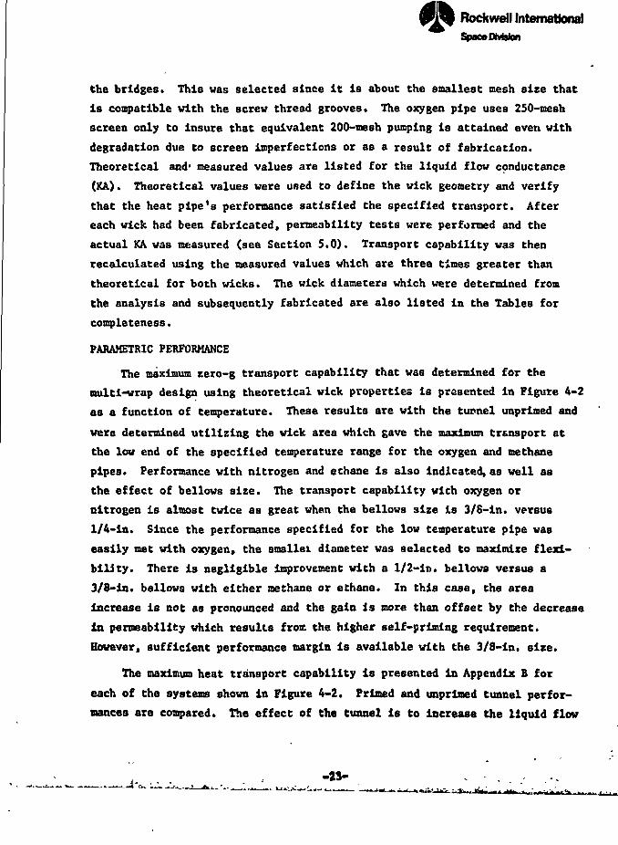
the bridges. This was selected since it is about the smallest mesh size that
is compatible with the screw thread grooves. The oxygen pipe uses 250-mesh *
screen only to insure that equivalent 200-mesh pumping is attained even with ' *<
degradation due to screen imperfections or as a result of fabrication. ,'J '
Theoretical and1 measured values are listed for the liquid flow conductance ?<$
(KA). Theoretical values were used to define the wick geometry and verify >»
that the heat pipe's performance satisfied the specified transport. After "•$.
each wick had been fabricated, permeability tests were performed and the *
actual KA was measured (see Section 5.0). Transport capability was then \
recalculated using the measured values which are three times greater than .1
theoretical for both wicks. The wick diameters which were determined from {
the analysis and subsequently fabricated are also listed in the Tables for ^
completeness. <4
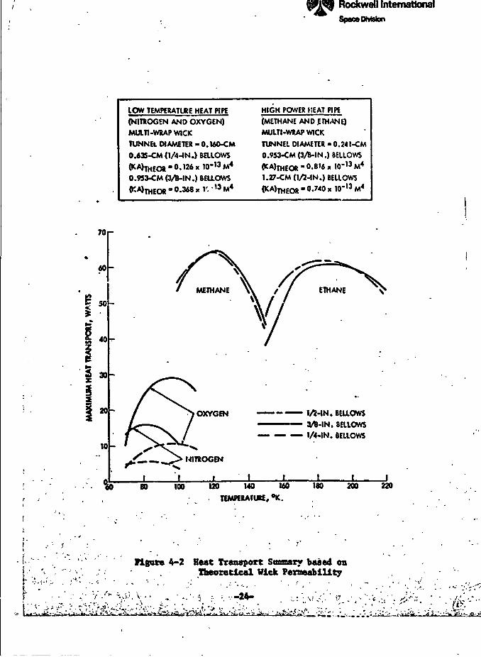
PARAMETRIC PERFORMANCE J
The maximum zero-g transport capability that was determined for the &
multi-wrap design using theoretical wick properties is presented in Figure 4-2 J
as a function of temperature. These results are with the tunnel unprimed and
were determined utilizing the wick area which gave the maximum transport at
the low end of the specified temperature range for the oxygen and methane
pipes. Performance with nitrogen and ethane is also indicated, as well as
the effect of bellows size. The transport capability with oxygen or
nitrogen is almost twice as great when the bellows size is 3/6-in. versus
1/4-in. Since the performance specified for the low temperature pipe was
easily met with oxygen, the smaller diameter was selected to maximize flexi-
bility. There is negligible improvement with a 1/2-in. bellows versus a
3/8-in. bellows with either methane or ethane. In this case, the area
increase is not as pronounced and the gain is more than offset by the decrease
in permeability which results froc the higher self-priming requirement.
However, sufficient performance margin is available with the 3/8-in. size.
The maximum heat transport capability is presented in Appendix B for
each of the systems shown in Figure 4-2. Primed and unprimed tunnel perfor-
mances are compared. The effect of the tunnel is to Increase the liquid flow
\ \-'•-•"•;• ".•"•"I -^' '! ITTV";'.-.-.v•?!;;•...-•;
70
S"40
30
20
10
Rockwell InternationalSpace DMsfcn
IQW TEMPtRATURE HEAT PIPE
(NITROGEN AND OXYGEN)
MULTI-WRAP WICK
TUNNEL DIAMETER - O.WO-CM
O.A35-CM (1/4-IN.) BatOWS
HIGH POWER HEAT PIPE
(METHANE AND .ETHANE)
MULTI-WRAP WICK
TUNNEL DIAMETER -0.241-CM
0.953-CM (3A-IN.) BELLOWS
0.9S3-CM (3/B-IN.) BELLOWS 1.27-CM (1/2-IN.) BELLOWS
0.740 » IO'13 M4
OXYGEN
NITROGEN
1/2-IN. BELLOWS
3/ft-IN. BELLOWS
1/4-IN. BELLOWS
I100 U0 140 MO
TEMPERATURE, °K.ISO 200
• r
•'-> . ; • - • - ' -ff i
figure 4-2 Heat Transport Soaaary baaed enTheoretical Wick Permeability
? -24- .'-v'/.-V .
220
i.\
y/ - *•
. . - , - - . , . . . ._ — „, ^^^.I I | I ' • - 'TS
/I
Rockwell InternationalSpace OMslon
conductance . (KA) where
tt ' (KA)Wick * (KA)Tunnel (4-?)
Hence, the smaller the wick's conductance, the more dominant is the effect of
the tunnel. As a result, improvements are most pronounced for nitrogen whose
wick permeability is Inhibited by the self-priming requirement and, correspond-
ingly its relatively low wicking height factor (H). On the other hand, the
higher the vapor losses (i.e., the smaller the values of F), the smaller the
gain due to a primed tunnel.
Also included in Appendix B are the performance predictions for optimized
spiral artery designs with methane and oxygen and 3/8 and 1/4-in. bellows, i
respectively. A comparison of Figures B-l and B-3 shows approximately 202 f
higher performance for the spiral design with methane. In the case of i
oxygen, there is about a 2:1 increase (cf. Figures B-6 and B-8). The higher
transport is derived from the higher flow conductance of the spiral wick. -.'
However, this wick is more difficult to fabricate than the multi-wrap design, "':
particularly in smaller diameters. Furthermore, the realiability of the multi- .1
layered system has been established with a non-condensible gas present. As -,i
a result, since its predicted performance margins are adequate, the multi- 1>i
wrap was selected as the baseline design. 3
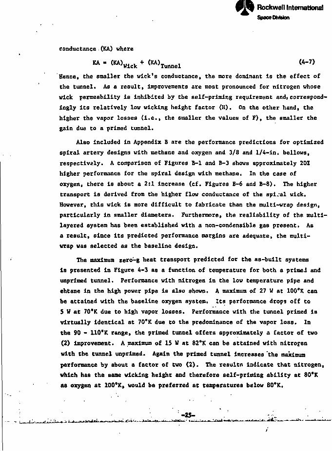
The maximum zero'-g heat transport predicted for the as-built systems (-
1s presented in Figure 4-3 as a function of temperature for both a primed and
unprlmed tunnel. Performance with nitrogen in the low temperature pipe and
ehtane in the high power pipe is also shown. A maximum of 27 W at 100°K can
be attained with the baseline oxygen system. Its performance drops off to
5 V at 70°K due to high vapor losses. Performance with the tunnel primed is
virtually identical at 70"K due to the predominance of the vapor loss. In k|
the 90 - 110°K range, the primed tunnel offers approximately a factor of two
(2) improvement. A maximum of 15 V at 82°K can be attained with nitrog-en
with the tunnel unprlmed. Again the primed tunnel increases 'the maximum
performance by about a factor of two (2). The resultn indicate that nitrogen,
which has the same wicking height and therefore self-priming ability at 80°K
aa oxygen at 100°K, would be preferred at temperatures below 80°K.
•-25-
Ff g fcaa^gaaaaaat ^^ J«
Rockwell InternationalSpacaDMsfcn
I
1
LOW TEMPERATURE HEAT PIPE
(NITROGEN AND OXYGEN)
MULTI-WRAP WICK
0.63S-CM (1/4 IN.) BELLOWS
TUNNEL D!AMETER « 0.160 CM
• 0.386 K«T5 CM4
HIGH POWER HEAT PIPE
(METHANE AND ETHANE)MULTI-WRAP WICK
0.953-CM (3/B IN.) BELLOWS
TUNNEL DIAMETER = 0.241 CM
'2.5x10-5 CM*
180
160
140
1 120
40
20
PRIMED TUNNEL
UNPRIMED TUNNEL
J_ _L60 80 100 120 140 160
TEMPERATURE, K,180 200 220
Figure 4-3 Beat Transport Snaaary Baaed onMeasured Wick Permeability
•.J.-TA.-ki,77-AP-0088
Rockwell InternationalSpscoDVWon
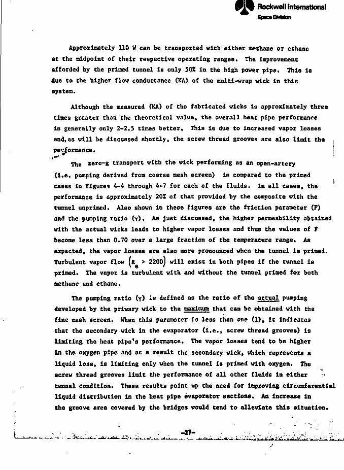
Approximately 110 W can be transported with either methane or ethane
at the midpoint of their respective operating ranges. The Improvement
afforded by the primed tunnel is only 50Z In the high power pipe. This is
due to the higher flow conductance (KA) of the multi-wrap wick in this
system.
Although the measured (KA) of the fabricated wicks is approximately three
tines greater than the theoretical value, the overall heat pipe performance
is generally only 2-2.5 times better. This is due to increased vapor losses
and,as will be discussed shortly, the screw thread grooves are also limit the
pev|ormance.. •«•''
the zero-g transport with the wick performing as an open-artery
(i.e. pumping derived from coarse mesh screen) is compared to the primed
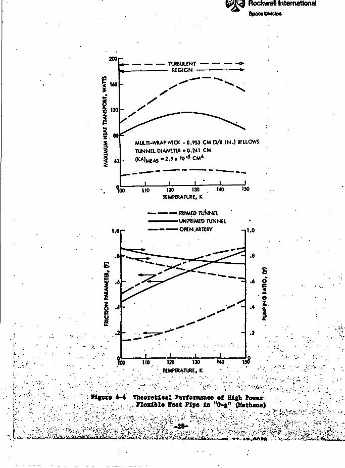
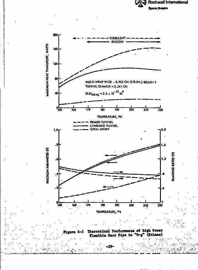
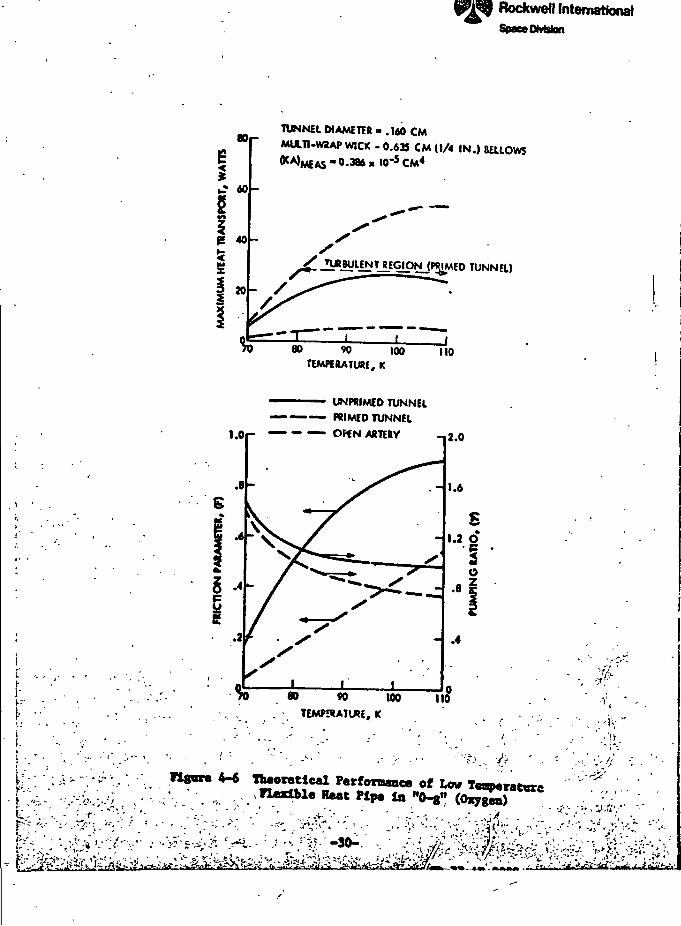
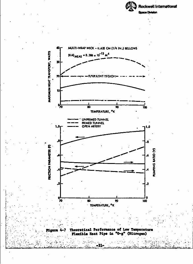
cases in Figures 4-4 through 4-7 for each of the fluids. In all cases, the
performance is approximately 20% of that provided by the composite with the
tunnel unprimed. Also shown in these figures are the friction parameter (F)
and the pumping ratio (Y). As just discussed, the higher permeability obtained
with the actual wicks leads to higher vapor losses and thus the values of F
become less than 0.70 over a large fraction of the temperature range. As
expected, the vapor losses are also more pronounced when the tunnel is primed.
Turbulent vapor flow (R > 2200J will exist in both pipes if the tunnel is
primed. The vapor is turbulent with and without the tunnel primed for both
methane and ethane.
The pumping ratio (y) is defined as the ratio of the actual pumping
developed by the primary wick to the maximum that can be obtained with the
fine mesh screen. When this parameter is less than one (1), it indicates
that the secondary wick in the evaporator (i.e., screw thread grooves) la
limiting the heat pipe's performance. The vapor losses tend to be higher
in the oxygen pipe and ac a result the secondary wick, which represents a
liquid loss, is limiting only when the tunnel is primed with oxygen. The
screw thread grooves limit the performance of all other fluids in either
tunnel condition. These results point up the need for improving circumferential
liquid distribution in the heat pipe evaporator sections. An increase in
the groove area covered by the bridges would tend to alleviate this situation.
-27-
; /•
jj-'}
« —-1-, -—=-•—•,j~rt^-->».,,P.-^,._... t *\»?rQj-'»- 0lr"~"~" " 'P-"-JI—--"—"™T|
Rockwell InternationalSpace DMston
200 r
5 160
120
»
40
TURBULENT «••REGION »•
MULTI-WRAP WICK - 0.953 CM (3/8 IN.) BFLLOWS
TUNNEL DIAMETER -0.241 CM2.5 x W5 CM4
I5r JL _L110 120 130
TEMPERATURE, K140 ISO
.e
S .4
.2
— PRIMED TUNNEL• UNiDIMED TUNNEL
— — OPEN .ARTERY -11.0
.8
I
-Io
.4 I
110 120 130
. TEMPERATURE, K
140
V '
Vignre 4-4 Theoretical Performance of High PowerFlexible Beat Pipe in "0-g" Qfathane)
V-: ''4
~4
••/
I
Rockwell InternationalSpace OtvWon
200
5 160
120
<I 80X
40
— — — ——TURBULENT -• REGION -
MULTI-WRAP WICK - 0.953 CM (3/B IN.) BELLOV-S
TUNNEL DIAMTER = 0.241 CM
^50 160 170 180 190 209 210 220
TEMPERATURE, °K
•— PRIMED TUNNELUNPRIMED TUNNELOPEN ARTERY -»t.O».or
.8
I -g
.2
1.6
.8
.4
150 160 170 180 190 200 210 220
, TEMPERATURE, °K
rigor* 4-5 Theoretic*! Performance of High PowerFlexible Heat Pipe in "O-g" (Ethane)
-29-
rr r-3-*-— -*-"rr
I8'
TUNNEL DIAMETER - .160 CM
MULT1.W2AP WICK - 0.631 CM (1/4 IN.) BELLOWS
• 0.386 » w*5 CM*
r
^_n«ByLENTJEGIpNjf«IMEO TUNNEL)
i.or —
80 90 100 110TEMPERATURE, K
UNPRIMED TUNNEL— PRIMED TUNNEL
- — OHN ARTERY
«««•
» W 100 II
TEMPERATURE, 1C
tteoretieal Perfenumca of. 1«dble Heat Pip, to
A?\-^Myj^^^^
•*•« •if ^""1 • •• • •'. VJliii n MinH — n - *•
kwell InternationallOMston
>
!
• •
ii
• " -"-,f' i< ' • .
. " • ' . ' ." -'4-"' / ' '•&.;
' - '• '--«,' v // - : . ' " •'•<:-& . . •
B T C • - , , • • . .
• - •£,; ;v<y;fty" %", !,-• --a M.-'., - f.'
-•• -v - ' ; •« y;;-- -1- ..-' ",r.>. • • - ' - - . V,V ;-\. -.'
^»,v; y^k^:.^;^- ft. ^•JijL*J;i*ti£S~ .<jt<--v
1 •4? /? .
•
.•
»J
*"
'l6
1 l ._
^- /J
J
/'l w *,1
<
*y~ *]
* " ' -"^f -,;
;.^^. >i' v, »l '
:*;•S&i,KL
It I le>~~" ' \ I I I.
Rockwell InternationalSpace DJvWon
40
I
|-"£ . W
1*
i 10
0
1.0
r. ' . - '*" . ' ' . ' ' * £
i **s
i •*i
.2
"- -. ,
i v : , . . . , - . - . ?
- MULTI-WRAP WICK - 0.635 CM (1/4 IN.) BELLOWS jf
^^MEAS * 0.386 « 10* M ?.j.'
*— : TiNBULENT .ECIO .•- —.--».• :y
••
T) 60
TEMPERATURE
1 ' UNPRIMEO TUNNtt— PRIMED TUNNEL
- — — OPEN ARTERY
- <j( -'**--"
•
-
—-.
1\ ^
90 loo -5er T •>• R - j' «,'. :
•
-
, •' . •
^^ ~
^ ...
0 80. 90 1C
. TEMPERATURE. °K
.. .
i " . . * ' " " ' v ' - ' ' • - • ' '
'•° i|
1
.8 S|
^t i•• § ,1» P4 I &
-e . !1
*" ' ^- - " - - . v - ""* ' P
:'"•':••';. ' " ? - " '."•;.. "-' : . • • ' " . - ',.-•• ' - , . ~ :- ']-• ' 'f'pr: '.': - |
'•, "-• ' :, '- . '-, . rigorti 4-7 Theoretical Perfoxoaae* of Low TodBpcratur* &•'; /\ ; .; . n«xlbl« Heat Pipe In "O-g" (Hierogen) |
"!-.;'; '•''.' -"• '-"•:* ''V^'- > '-'' - /:. "i:;<-V."-"'.--- ' ".; v '. . -31-'..-v:- •:-•, ::'^f^W^:v-:, - . ; > : •
,
'• i,
1Rockwell InternationalSpocvDMiion
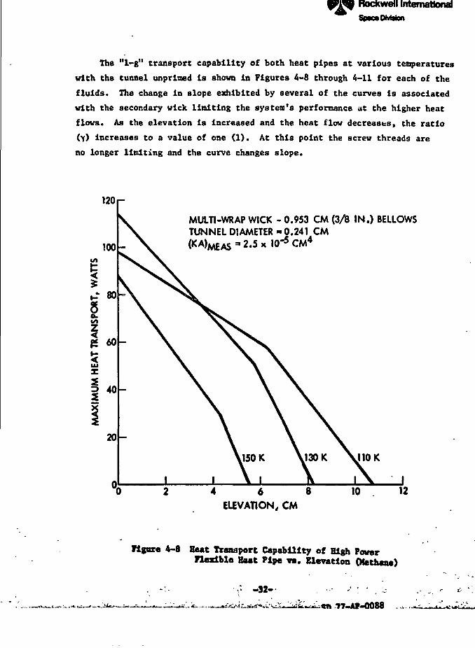
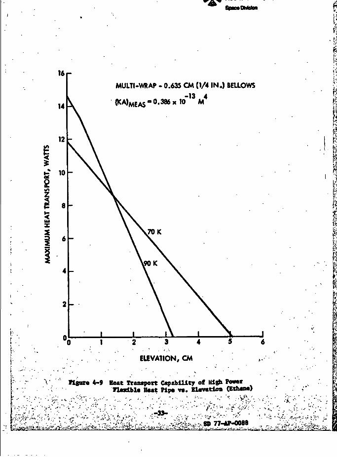
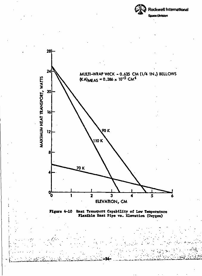
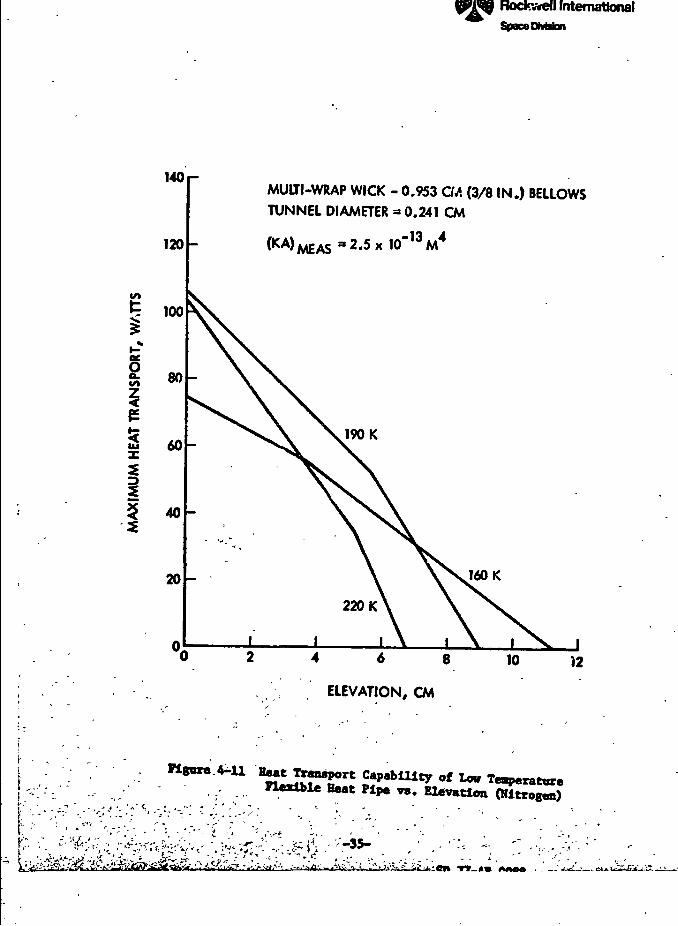
The "1-g" transport capability of both heat pipes at various temperatures
with the tunnel unprimed is shown in Figures 4-8 through 4-11 for each of the
fluids. The change in slope exhibited by several of the curves is associated
with the secondary wick limiting the system's performance at the higher heat
flows. As the elevation is increased and the heat flow decreases, the ratio
(Y) Increases to a value of one (1). At this point the screw threads are
no longer limiting and the curve changes slope.
120
100
-' 80
in
IUX
60
40
20
MULTI-WRAP WICK - 0.953 CM (3/B IN.) BELLOWSTUNNEL DIAMETER -0.241 CM
(KA>MEAS " 2-5 * 10~
110 K
4 6 8
ELEVATION, CM
10 12
Figure 4-8 Beat Transport Capability of High PowerFlexible Beet Pipe va. Elevation (Kethaae)
-32-
N
161-
RockweB International
MULTI-WRAP • 0.635 CM (1/4 IN.) BELLOWS
(KA)MEAS-0.386 x!<)"13M4
V
2 3 4
ELEVATION, CM
Figortt 4-9 Heat Transport Capability of HighTtadbte Bsat Pip* vs. Bl«vmtlon (Ethos*)
/£»
II
ifif
P
pH
- -,, -. .
" , ^ . " - 1
t ' 'i ' ». " , - '»"- . - ,' - ' ^~ -' •'-ti'
. . , , . , .-• . * . . ' • / • - . - • ' " - •• . - , , , -. .-• , '/
r ^^^^» . - " * * " " _ - '» - - ! „ " • j "~9*^ •- - • — '. ,., >* » • -^ ' 1
* ' . - • - - - - * < - - • " - • - ' '*'
1
„.-_. ,.
\l- .-^f^f-f^ ~^T; \7 ?.j-?r-.* T=vi L, - , - , -— »-• M-..T—.
-LCCg»XUUUJMil»rc»rt
Rockwell InternationalSpace DMston
MULTI-WRAP WICK - 0.635 CM (1/4 IN.) BELLOWS0.386 x 10'5 CM4
2 3 4ELEVATION, CM
Figure 4-10 Beat Transport Capability of Low TemperatureFlexible Beat Pipe vs. Elevation (Oxygen)
:>34-
attonalSpace DMston
MULTI-WRAP WICK - 0,953 CM (3/8 IN.) BELLOWSTUNNEL DIAMETER = 0.241 CM
(KA)MEAS=2.5x 10"13M4
ELEVATION, CM
,
•
«S«».**1 Capability of LowPipe v. Elevation
-an
-i'•6
«*Rockwell International
5.0 HIGH POWER HEAT PIPE FABRICATION AND TEST '
This section summarizes the results of the fabrication and test program
for the high power heat pipe which was the first to be fabricated. Since
this was a technology development program, both the fabrication and test
efforts necessarily involved some degree of trial and error. The discussion
below highlights some of the problems encountered and describes the method
of solution. The test program involved several thermal performance tests
with methane and with ammonia as well as investigative tests to help explain
the behavior of the pipe. Preliminary test results were presented at
the llth AIM Thermophysics Conference in 1976 (Reference 9).
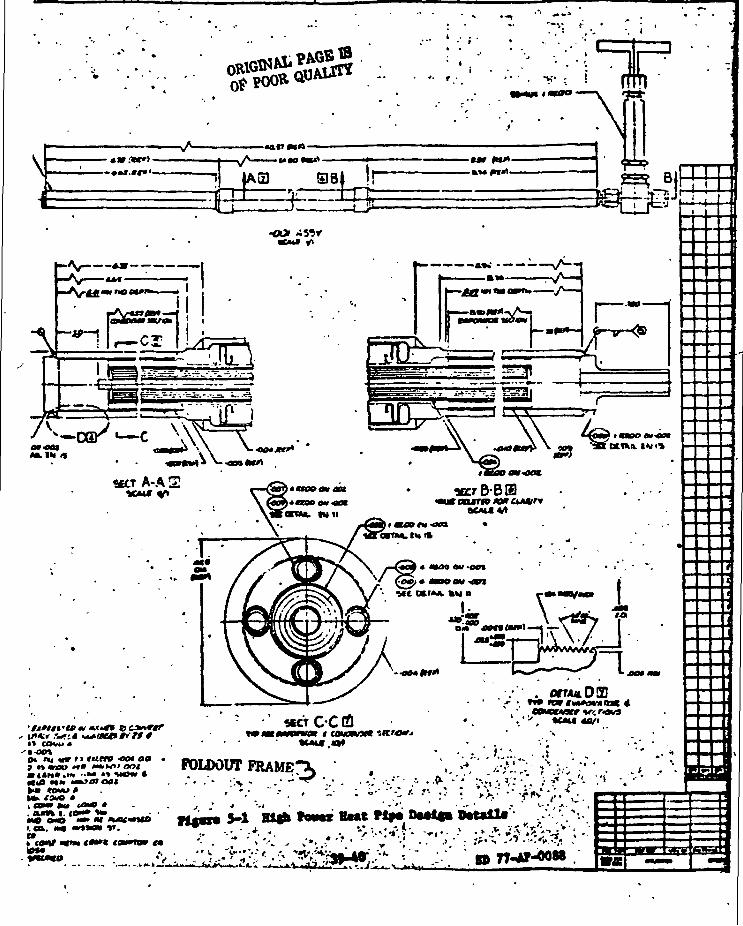
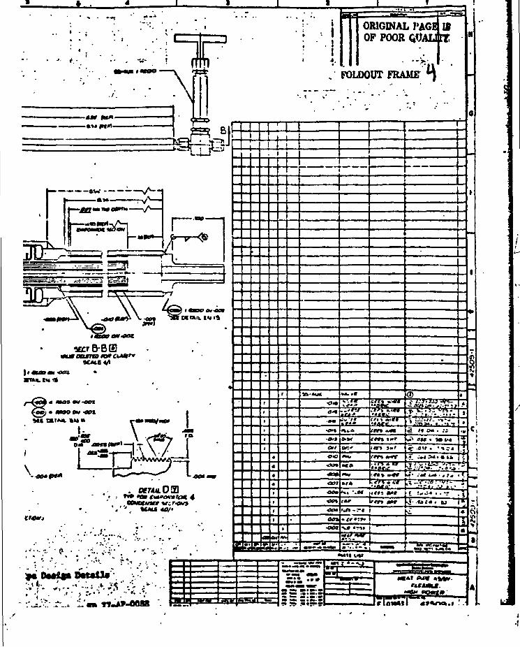
HEAT PIPE FABRICATION
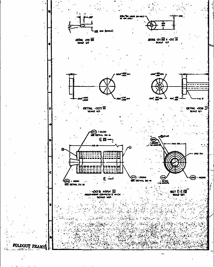
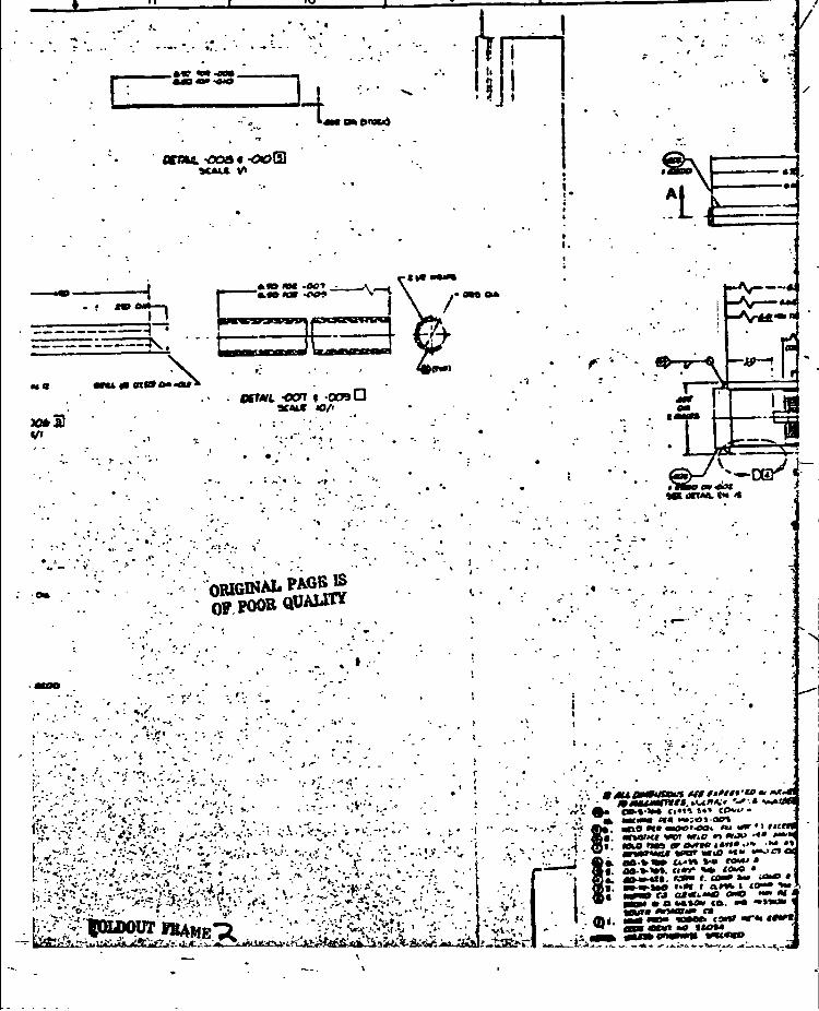
The high power heat pipe was fabricated in accordance with the assembly
drawing, Figure 5-1. The container consists of a 0.95 cm (3/8 in) flexible
metal bellows assembly with a length of schedule 80 tubing welded to each
end (Figure 5-2). The bellows is covered with a double braided wire sheatho
to provide a design burst pressure of 1.03 x 10 Pa (15000 psi). The ends
are machined and internally threaded with 72 threads /cm to provide circumfer-
ential wicking. The primary wick, as discussed in Section 4.0, is a spiral
multiwrap of 30 mesh screen encapsulated by a 200 mesh outer wrap. The
screen is cut on a 45° bias to provide flexibility. Four screen bridges are
used at the evaporator and condenser ends provide radial liquid distribution
(Figure 5-1) and are also 200 mesh screen.
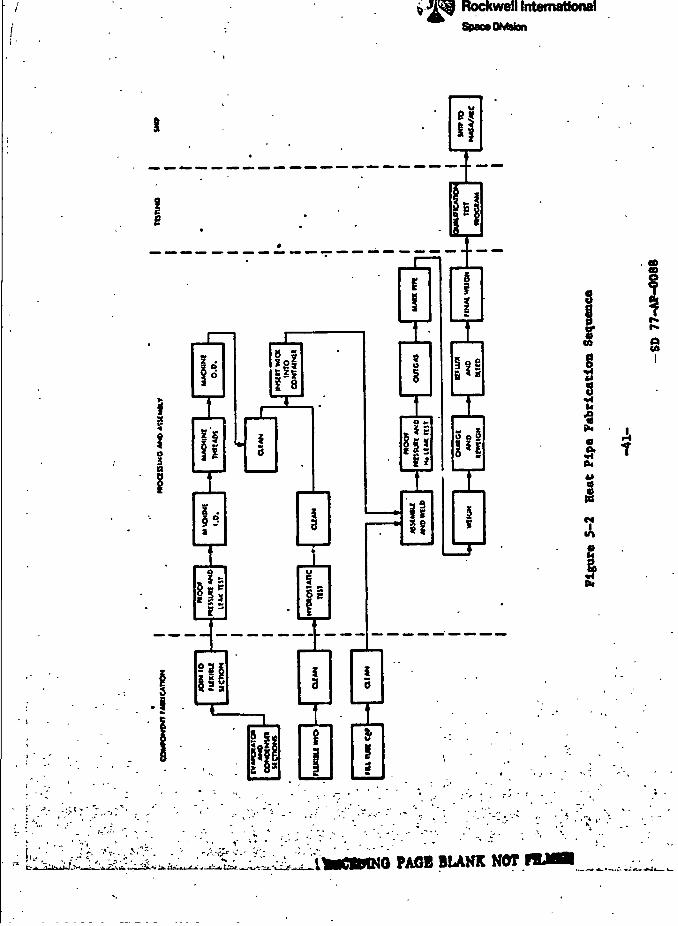
The fabrication and testing sequence for the high power heat pipe is
shown in Figure 5-2. A summary of the detailed fabrication and assembly is
described below.
Flexible Container
The flexible container was purchased as an integral unit with a length
of schedule 80 316 SS tubing welded at either end. The flexible container
geometry is shown in Figure 5-3 in the as-purchased configuration. Dimensions
are shown for both the high power and the low temperature heat pipe con-
" "
'-.-I*-*1*—I
FRAMSl• -.•-- W
aoat 091
'•' OCTML -005®JCAU V
VI I - . » ! • - •-*&>• ***~f*V\ -*-" I — -'t-™-***-^ tff
t> ,-V ~tf- I../.-: '•-:-. I -•- ' :> I '- -' - '
10
•coat -ooffl
wa •n*«iet0
^•OCT
*/•
. .»••
0RIGINAL_PAGBJSOP POOR
. »
• ' ' • • ' ' J ", -<•: T<. •,~ .* -. .
>-*
'. >'.'
c ;"'..' . •y -:^'-'Vt v.-v '-.r4v •* :•'• *.r-£~
v?v-'r:•-•-'>;; .v/<-:i-J. *»!• V-W
- »J> - • > • > „ ' »
..-•-V-W-i .-< •;_. ,.;
••'' -'t;v:i'";
-<» r. ••<"•••.!..-> «
' ~* * • '
- Vf;-'. "j TV
x; ••*• <- - '-•
— •-"/-i-f.-'^H
^-y^^. cmA^atggagg**
ffi ll
.1
L• «*-••
i.
-r--.t«- :^-
'. ^r1'-;-o .'.'
" v^-v;..'r-tSE>r
. ' • « . • • ' .
• . -, •, ><*i fl^></Tnit fftttfttt'to », Hx^t•'• 'r _ »MUMtmtt.t**»*i* '•*:* VWKM)
. •>•>•- ^« OD-«-«* rxt« >••• cov>/ •- - 0 _» ••(••• «r« •«•;<)> op*
-•- '"' MM. m0 »<• MOO'-OOt <u W » f icm' •' Ac. *r»«rxf wet «riO m «rjo •<• *»>1
..'' A . flj». «SU> laa or Outto t*n*>"» •*• •»' • •: ' z: . •ii»»'im «por MU> t" iM^rtac— -—i W*. oft-v*» a*»» >•• ro«u •9i. ao-v***. <!•*• %« <CMO *
«4. «0-»u». n«* r. <oi» »v ui«o »Int. BV-W-MO »••« > <x«vt i <OM* «MA« •*<•» » C««1.M« dMO MM M^ *HM • a «p»*av ca. •* ••>»»•> 1^ «ur« M»«VM> rt :
. <D«. MM M»> •HBfl (3Mf MT*t ««f«• W tB* ««W» •« <I0M
-i\•» »«Mk«n«N«_Li . ... «. -.-.i.x. .ttM
_ L_. . Y 1.1
\
~-T™-T~±-——i
& S
Rockwell InternationalSpace DJvMon
T&i
PAGE BLAHK NOT
is
S t
F<3
T i -—~r jr rr •*•' "•'••'fa.
Rockwell InternationalSpace OnMon
\
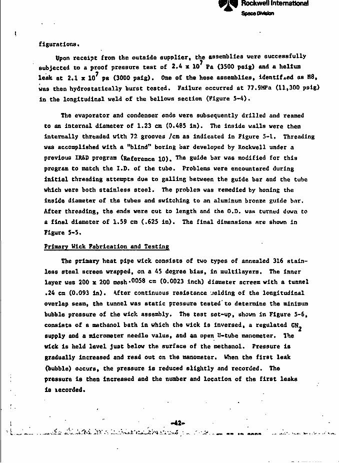
figurations.
Upon receipt from the outside supplier, the assemblies were successfullysubjected to a proof pressure test of 2.4 x 10 Pa (3500 psig) and a helium
leak at 2.1 x 10⁷ pa (3000 psig). One of the hose assemblies, identified as H8,
was then hydrostatically burst tested. Failure occurred at 77.9MPa (11,300 psig)
in the longitudinal weld of the bellows section (Figure 5-4).
The evaporator and condenser ends were subsequently drilled and reamed
to an internal diameter of 1.23 cm (0.485 in). The inside walls were then
internally threaded with 72 grooves /cm as indicated in Figure 5-1. Threading
was accomplished with a "blind" boring bar developed by Rockwell under a
previous IR&D program (Reference 10). Thfi guide bar was modified for this
program to match the I.D. of the tube. Problems were encountered during
initial threading attempts due to galling between the guide bar and the tube
which were both stainless steel. The problem was remedied by honing the
Inside diameter of the tubes and switching to an aluminum bronze guide bar.
After threading, the ends were cut to length and che 0,0, was turned down to
a final diameter of 1.59 cm (.625 in). The final dimensions are shown in
Figure 5-5.
Primary Wick Fabrication and Testing
The primary heat pipe wick consists of two types of annealed 316 stain-
less steel screen wrapped, on a 45 degree bias, in multilayers. The innerlayer was 200 x 200 mesh' 58 cm (0.0023 inch) diameter screem with a tunnel
.24 cm (0.093 in). After continuous resistance welding of the longitudinal
overlap seam, the tunnel was static pressure tested to determine the minimum
bubble pressure of the wick assembly. The test set-up, shown in Figure 5-6,
consists of a methanol bath in which the wick is inversed, a regulated CM.
supply and a micrometer needle value, and an open U-tube manometer. The
wick is held level just below the surface of the methanol. Pressure is
gradually increased and read out on the manometer. When the first leak
(bubble) occurs, the pressure is reduced slightly and recorded. The
pressure is then increased and the number and location of the first leaks
is lecorded.
-A2-
Rockwell International
SpmCfcUon
8 8 « 8• n n • a •> - N X > - N X
OZ
.|
«1
<ll l;l
B
ZoE6
s<Ma
< s0 I
oa
-o
o o o o2; m uj _
«/>S
*,
- ^ S 3 *O
^ w « - w «
S
IimCflMMQ PAGE BLANK NOT RLIIO
O
_itu
8
P»<A
«/>
i
• H,1
g
s
^;-.: -v v -^ t ^^n -^ i - ^A ' ' . ^ r-..',,!:* ,,.,
'V^fc.
Rockwell InternationalSpanDmsion
oooo
&fe2asb
1§
X
. /
Rockwell InternationalSpawDhMon
so
•«
8
3• • •
£ z z Z S ZK — —• O O 00
e a s 8 S .a
35
• • •• • • "7 7 7
5 £ £ - - -co * rx <Q § !fltx o» in *> «o ^•o co o o e o A
i£
a s 3oz
o
1 n l 5fc o 8
°* it0 ^5 s
i
:'V-"i '•' •'•-,-*"i -;',--';\-<--Xi«^v'.w v,?';-• " . '= •uaiL.^ J^Il-^fc^iL^-.. --C i ^fegS1^Sk-ig- ; .. X,i; vvl _^ -
Rockwell InternationalSpecaOMsfen
'H
GN,
AH
MANOMETER(WATER)
yWICK
J-
\METHANOL BATH
figure 5-6 Heat Pipe Wick Static Pressure Test Set-Up
-46-
SD 77-AP-0088

T! Rockwell International
An acceptance level of SO percent of 200 mesh pumping vas established
for the high power heat pipe wick. For a nethanol bath and a water manometer,
the required t H is gives by
.AH- 0.8 M o.(5-1)
where M is the mesh site, v. is the surface tension of the test fluid
(nethanol) at the measured test temperature, and P is the density of themfluid in the manometer at ambient temperature. For a methanol bath and a
water manometer at 20*C, the minimum acceptance level is 5.84 cm. On the •
first try, the wick had a single leak at 5.6 cm. The leak was found to be
due to an enlarged pore caused by movement of the screen wires during tack
welding. The wires were repositioned and a 5.85 cm head pressure was \
achieved.
The wick assembly was then tested for flow permeability in the set-up
described in Section 4.0 (Figure 4-1). The wick was tightly sealed with
plastic and tape, leveled, and water at a fixed head pressure allowed
to flow through the wick. The pressure drop across the wick was measured by
pressure taps at either end leading to an open ended manometer. Flow rate
samples were collected at 5 pressure settings in the range of 2.54cm to 15.24cm
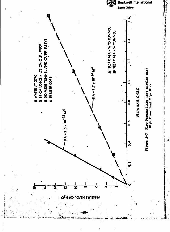
(1 to 6 in) of water. Results of the test are shown in Figure 5-7.
The test was repeated without the mandrel to determine the flow permeability
of the system with the tunnel primed. These results are also shown in
Figure 5-7. The permeability x area (KA) product was determined from theexpression
AT..(5-2)
where
* is the flow rate (kg/sec)
L Is the overall length (a)2
|i is the viscosity S-s/m
p is the fluid density (kg/m3)
K is the permeability (a2) and
-47-
SD 77-AP-OOSM
\\
°251U x
& 2Z ui*> oc2 p
£ 8: § 8• O 0 •
\\\\\\ K
p^•<X
2«
Rockwell InternationalSpace OMBfan
IIJ $i i
< <O O
\\\\
CM
00•
o
•oo
(M•
O
<N O
YO 'OV3H 3«nSS3W
UUJ
§
aia ,&:
a co a.
&«•n a^S•SM
giiS*4
8*I-
a
J
' -48-r -^-!
Rockwell InternationalSpace Division
A is the flow area (a*)-13 4
For the unprimed tunnel, KA was calculated to be 2.5 x 10 m • The ->-.
theoretical value for 30 mesh screen with a .74 cm OD assembly is . "• •
0.86 x 10 n , or a little over one-third of the value calculated from test
data. The difference in permeability was hypothesized to be due to gaps
between the layers of 30 mesh screen. An analysis was performed to determine
what size and geometry of gap could reconcile both the permeability data
and the total volume of the wick. The coarse area of the wick was formed
from a 4.45cm length of 30 mesh screen with a thickness of .061cm, for a2
total area of .271cm . The available area between the inner and outer
wraps of 200 mesh screen is 0.346cm ; thus the area of the gap is .075:m .
The gap was assumed to be a rectangular channel of thickness t with width w,
where the permeability is defined as t /12. The KA of the gap was assumed
to be the difference between the measured KA ot the system and the theoretical
KA of the 30 mesh screen, or 1.3 x 10~ n. The gap thickness was solved *
from the relationship
^A -18xlO-13
where A is the area of the gap «• 7.5 x 10 n .g -4
Solving for t and w yields t • .0537cm, and w » 1.4cm. The calculated '•
gap size was felt to be conservative since the additional flow area of the
inner and outer screen was not accounted for, and because the gap would be
expected to be uniformly distributed over the length of the 30-mesh spiral
wrap. For the worse case, however, the question arose would such a gap, if
it exists, be able to prime? Using property data for methane at the upper *
end of the ICO to 140°K range where the surface tension is lowest, the ;
predicted priming height is ~ .85cm which is just equal to the maximum ,elevation of the top oi the wick from the bottom of the Inside of the pipe.. *
The gap would therefore be expected to prime. 4
After the permeability test was completed, the wick assembly was I*
cleaned and the end close-out caps (Figure 5-1) were installed. The wick *
close-off caps and the wick were cleaned as follows: 3
f
\. • \
Rockwell InternationalSpace DivUm
(a) Hot flushed with trlchlorethylene for 5 minutes
(b) Flushed with HacDermid S487 at 160F for 10 minutes
(c) Rinsed with tap water - followed by a DI water rinse
(d) Immersed in 201 UNO, at 170F for 10 minutesJ **
(e) Rinsed with DI water
(f) Dried at 300F for 1 hour
One wick close-off cap with a hole and one without a hole were butted up
against each end of the 30 mesh center layers and the overlap of the outer
200 mesh screen was resistance welded to the circumference of the close-off
caps. A final static pressure test was acceptable - the first "leak"
occurring at 6.3 cm A U. A solid tapered stainless steel plug, approximately
0.25 cm long, was pressed into the hole of the one end cap.
Wick Standoffs (Bridges)
Eight pieces, 2.0 cm wide by 25 cm long, of the 200 mesh screen were
wrapped around .24 cm diameter mandrel and resistance welded intermittently
along the 25 cm length. Four were cut to 21.6 cm and four were cut to 16.5 cm
long to become the standoff wicks for the evaporator and condenser sections
respectively.
Eight 347 stainless Jteel rods - 0.16 cm diameter were cut to the same
lengths as the standoff wicks. These rods, when inserted into the standoff
wicks, keep the primary wick centered in the evaporator and condenser
sections and insure coatinuity between the primary wick and the internal walls
of the heat pipe.
Fill Tube and End Cap
A fill tube and end cap were machined from 316 ss per the I'jnensions inFigure 5-1. The I.D. of both ends was counterbored 0.064 cm deep by 1.27 cmdiameter to match the step in the fill tube and end cap.
Final Assembly
All the parts for a complete high power heat pipe assembly as shown
in Figure 5-8 were' cleaned with the same procedure described above. After
the wick was inserted into the flexible hose assembly and the standoff vicks
•M!*
\>
:
-30-L Ji. 4C*.UAJh int.. m ii
-U.
Rockwell InternationalSpace Division
^. ••» •• -*t-"•"'—•••" *-r*i • "j*s- K.*
?•?--:•" • ' X-jV'ifj:^*;'fc'-ij-' SiV-Y^-v .-V^
ORIGINAL PAGEJIBOF POOR QUALITY
coeo
I
Rockwell Internationa)Cjpsoo OMttoo
and rods were IP?tailed, the end cap and fill tube were gas tungsten arc (GTA)
welded to the condenser and evaporator sections respectively, using 316
stainless steel filler alloy. j
The unit was successfully proof pressure tested at 2.4 x 10 Pa (35007 i
psig) and helium leak tested at 2.1 x 10 Fa (3000 psig). j
BAKEOUT AND FILLING ',
For the bakeout and filling operations, a high pressure high vacuum i
valve was attached to the fill tube end of the pipe. Initially, a Uhitey
model 3NBS4 valve was used, but problems with leakage through the stem I
packing were encountered. The valve was subsequently changed to a Nupro model i
S4UK which is a high vacuum cryogenic valve with a bellows sealed stem. The
Nupro valve worked exceptionally well during all filling and testing phases.I
Bakeout I
The heat pipe assembly was inserted into a bakeout shroud and hooked up
to a high vacuum system. The pipe was baked out under vacuum at 121°C
(250F) for 16 hours. The vacuum was maintained below 10~ micron after the ;
initial decay.
Filling
The theoretical fill determination was calculated based on the measured
weight and dimensions of the primary wick, the standoff bridges, and the -
container. The theoretical 100 percent fill charge is 13.8g based on
operation with methane at the minimum test temperature of 100'K. The pipe
was charged with 14.8g (7 percent excess) and was weighed to verify the charge.
TEST PROGRAM
The high power heat pipe was subjected to a series of thermal tests to
determine its performance under various conditions of temperature, tilt, and
fluid charge. Initial tests were conducted with methane at 100 to 140"K.
Initial test results indicated that the wick was not achieving full pumping.
A series of parametric tests were run using ammonia at 280°K to try and
determine what was causing the lover-than-expected performance. Mass
spectrometerand gas chromatography tests were also run on the methane to see
I
p 1Rockwell InternationalSpanDMston
if their vere excess imparties that might have caused bubbles to form in theT-
wick. Results of the overall test program are discussed in the following >i
paragrcphs. ?<
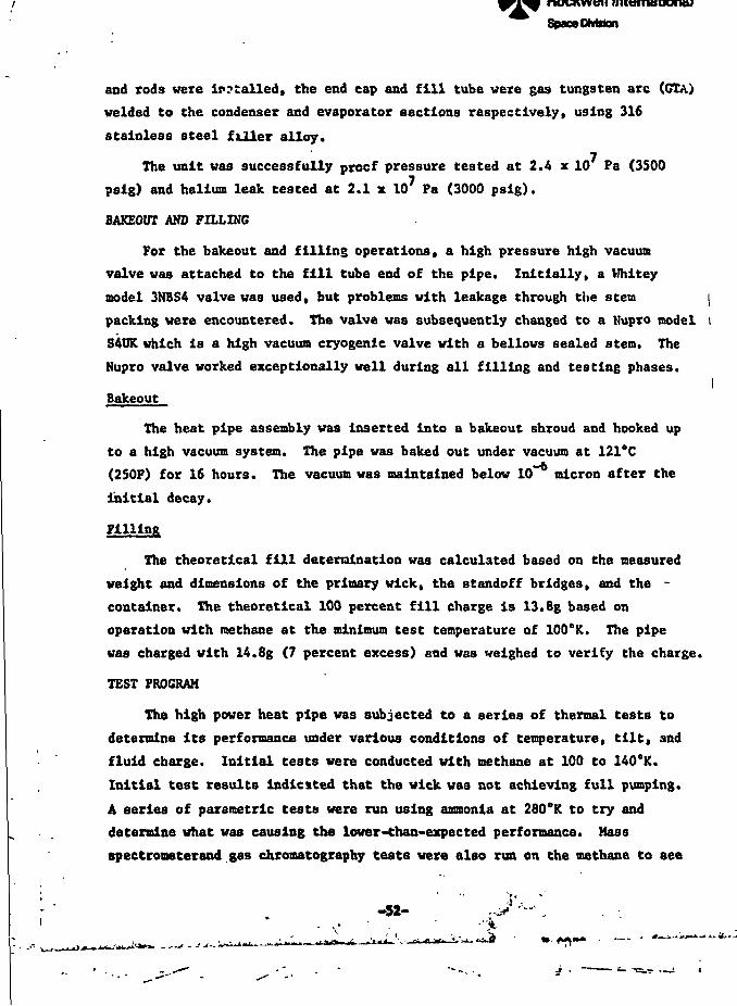
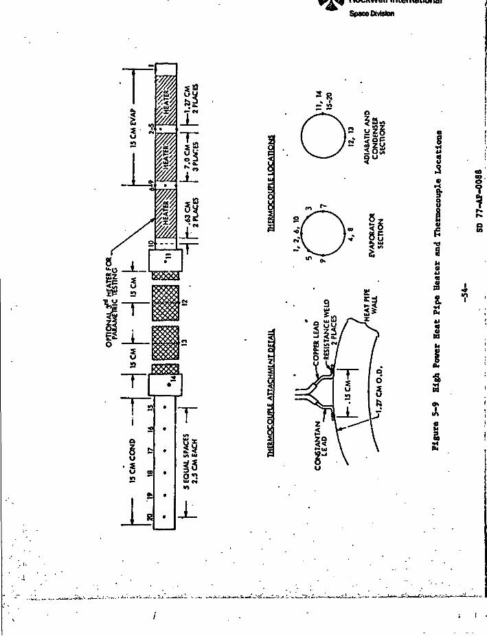
Methane Tests *' *•
Test heaters and thermocouples were installed on the heat pipe as . ''„<
indicated in Figure 5-9. Thirty copper-constantan thermocouples were spot ..-]
welded to the heat pipe. Each leg of the pair was separately attached so
that the heat pipe wall becomes part of the electrical circuit. This ensures
that the temperature indicated will be a true reading and permits continuitychecking between the vires and the wall as well as between the two wires. A
single roll of calibrated 28 gage thermocouple wire was used for all hookups.
Figure 5-10 shows the heat pipe after installation of the heaters and thermo-
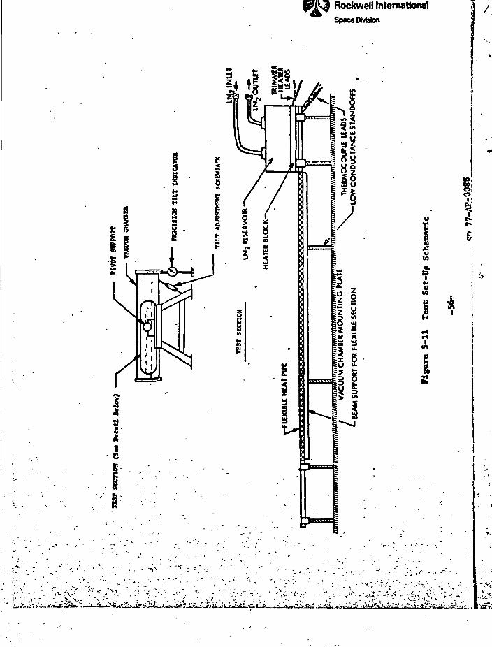
couples. The heat pipe was then installed in the test fixture and leveled.
The test fixture, shown schematically in Figure 5-11, consists of a level
test platform which is supported off a mounting plate by low conductance o
standoffs. Cooling is provided by an aluminum LN. reservoir which has a
heater block between it and the heat pipe for temperature control. The
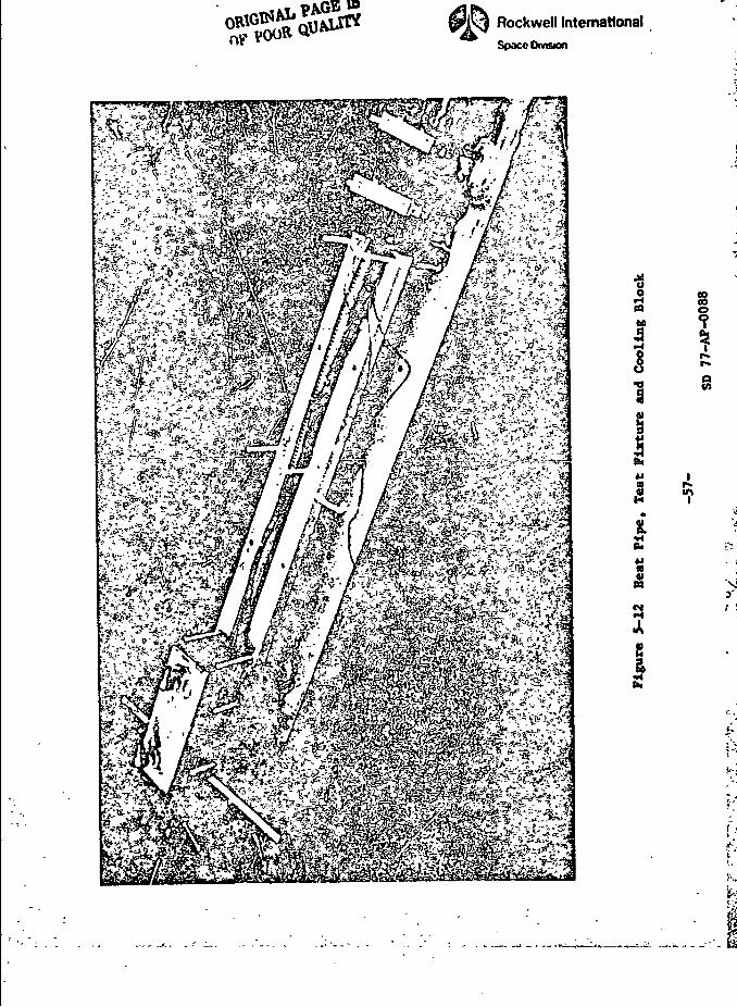
heat pipe, mounting tray and LN. reservoir are shown prior to final
installation in Figure 5-12.
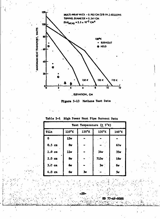
The pipe was thermally tested in a straight configuration in the rcnge
of 100 to 140°K. Figure 5-13 shows burnout data at 140"K as a function of
tilt compared to theoretical predictions. The 67 watt burnout at 0.5 cm '<
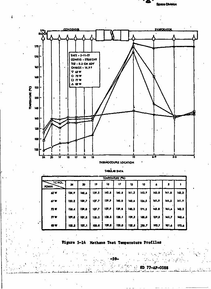
indicates that the wick was primed. Detailed temperature profiles for
62w, 72w, 77w and 82w are shown in figure 5-14. At 62 watts, the pipe was
nearly isothermal with an average evaporator-to-condenser temperature drop _>
of about 2°C (at 40 watts, the pipe waa isothermal within 1°C). The profile . 5for the 72w case seems to indicate a secondary wicking system burnout since
thermocouple numbers 1-5 are still near the vapor temperature. ?''|
As shown in Figure 5-13, the burnout values at higher tilts were all y>
significantly below theoretical, and all indications were that the wick was ->
not primed. In fact, the 62 watt burnout point at 0.5 cm tilt could not be
duplicated in suh&aquf.nt tests. A summary of the burnout points for the
entire test matrix is shown in Table 5-1.
-ss-BD 77-AP-0088 A .
.
.
\ •
8
ri,2 «s
vM
Jw/,
IIfM7,
Pi^
s aowts5NO.r»
13s uh
.0
<1 ^x2 s^-r
^_i_59
iQ
§ *s
Jj
T
J_
Rockwetl InternationalSpace Division
5
33
i«
•d
i
i
II
3
]•o• I
ORIGINAL PAGE IBOP POOR QUALITY
Rockwell InternationalSpace Division
•7
;;K °**>p^>;$p
:X' ^^^r^-,:- tlM^feOCk
ih
i
egC
2S
so
• 1
s
7?W*
Rockwell InternationalSpace Division
t- fc_ ££cf.Aa 5 1*9
341
oM
f«
0.«
I
! k
L- • :
".•>." n
J IRockwell InternationalSpace Division
3f-4
J•O
9
iJjfe
aj,
CO00o
Rockwell InternationalSpace Division
I20i-
100
*? 80
5-
40
20
MUITI-WRAPWICK - 0.953 CM (3/8 IN.).BELLOWS
TUNNR DIAMETER • 0.241 CM
~5 CM*
IWftC
• BURNOUT
HELD
110 K
4 & 8 10
. IUVATION, CM
Figure 5-13 Methane Teat Data
12
Table 5-1 High Power Heat Pipe Burnout Data
Test Temperature (+ 5°K)
Tilt
0
0.5 cm
1.0 en
2.0 cm
3.C cm
4.0 cm
110"K
15v
8w
llv
8w
DV
6v
120«K
-
-
-- '
-3w
130°K
- ^34v
715w
5w
'-
140*K
-67w
35v
18w
6w
5v
-58- . ' -;;..- --I .;>/,,. -.-c> •'• -'•"' 8D 77-AP-0088
nVsLfafcJdU.^ • &:j-ifa.. .v .-. ,>^~; ..--•,('/<iiL
Rockwell InternationalSpanOMBion
I
figure 5-14 Methane Test Tenperature Profile*
-59-•\
--»• • - s - • —
r--s'S
DAU-2-11-77
CONf 1C - JT1AIGHT
Tiff - 0.3 CM ADV
10
TMeutocouni LOCATION6-* M
TIMHIATlAf PK>
"•<^U:NO.POW«>V.^
62W
«7W
nw
77W
«W
M
1».»
IJJ.t
119.4
UM
ta.i
10
M0.«
W.7
IJ».«
IV.I
m.i
i*
IJ9.I
ijr.y
W.T
1JS.J
UO.I
»
MO.I
ii».t
m.»
i».t
m.o
17
wo.e
MO.O
«»».•
w. i
ISO.O
is
UI.2
140.6
140.1
IJ».l
1»4
•10
14J.»
I56J
171. 1
IH.O
JM.T
6
141.0
MI.9
U».«
UM
W.7
I
Ul.l
MM
•MM
MI.7
KI4
1
I4S.I
Ul.t
UJ.J
M1.4
179.4
]]
V?S«
j
1
Rockwell InternationalSpace OnWon
The pipe was evacuated and recharged with methane. The pipe was
refluxed for 4-6 hours and vented several times to purify the fluid. It was
Hypothesized that the low burncut levels were caused by non-condensible gas
impurities which caused the pipe not to prime. In all subsequent tests, the
burnout power levels did not improve, and the 67 watt burnout point at 0.5 cm
tilt or at any other tilt including a 0.5 cm reflux could not be duplicated.
At that point, the test results were reviewed in detail with the NASA
Technical Monitor. It was decided to forego other tests in various bendconfigurations in order to further investigate the problem. Three possible ;
causes were postulated: (1) depriming or bubble formation due to trace
contaminants or gas generations; (2) a secondary wicking system limitation;
and (3) a hole or open seam in the composite wick assembly.% -
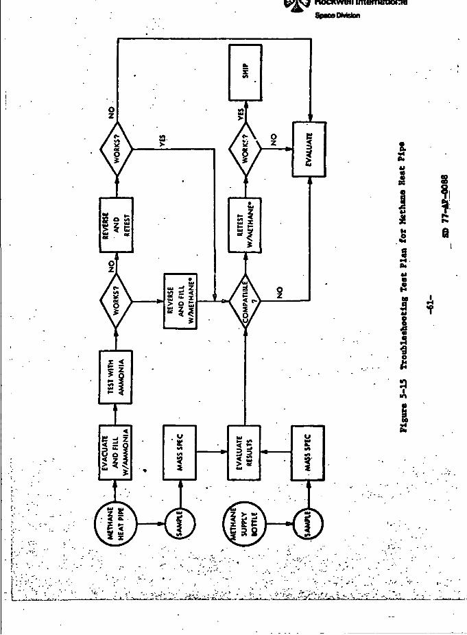
In order to ascertain which of these might be the cause, a trouble-
shooting plan was formulated. The troubleshooting plan, shown in Figure 5-15,
consisted of a series of tests and evaluation to systematically narrow down
the possible causes of failures to a single alternative. The plan called
for gas analysis of the methane, testing with ammonia; and reversing the
evaporator and condenser of the heat pipe and listing with either methane
or ammonia.
Gas Analysis Tests
Gas samples were taken from the heat pipe, the methane supply bottle
(ultra high purity grade) and from a newly purchased supply bottle of
research purity methane. Samples from the heat pipe and supply bottle were
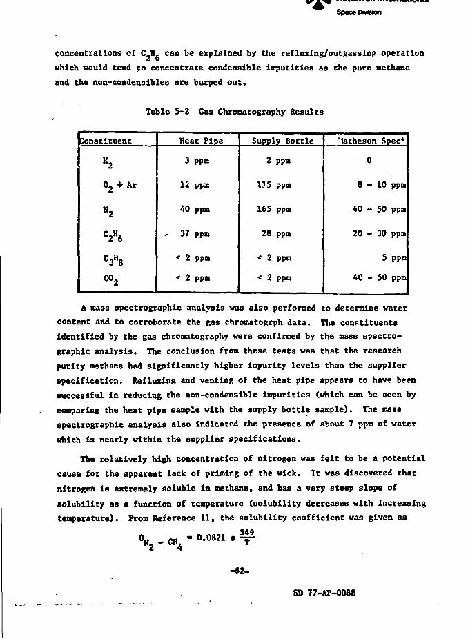
initially tested at Rockwell on a gas chromatograph. Results of the analysis
are shown in Table 5-2. Matheson purity specifications (typical analysis)
are also shown for comparison.
Several conclusions are evident from Table 5-2. First, the impurities
in both the heat pipe and the supply bottle are considerably higher than
quoted by Matheson. This had been suspected based on previous experience
cited by the Technical Monitor. Second, the impurities in the heat pipe
and supply bottle are of roughly the same order. Therefore, evidence of
corrosion or internal gas generation is not apparent. The slightly higher
-60-
SD 77-AP-0088
Rockwell International
SpiMOMGtan
£fe«l
2«9•-I.CM«J
II
^
1
9m
sII*
8
J,f
'5'j
3
I3
I
I
'-^ • j-. •'"''"y''..«• y s * •, -.-',•'*g'->.y'-y- - i-./^-v .,,.•> '^_.-: - J
> ^
Rockwell InternationalSpace Division
-IJ
«
*
concentrations of C.H, can be explained by the refluxing/outgassing operationZ owhich would tend to concentrate condenslble imputities as the pure methane
and the non-condenslbles are burped out.
Table 5-2 Gas Chromatography Results
Constituent
K2
0, + Ar
N2
C2H6
C3H8
co2
Heat Pipe
3 ppm
12 ppx
40 ppm
37 ppm
< 2 ppm
< 2 ppm
Supply Bottle
2 ppm
175 ppm
165 ppm
28 ppm
< 2 ppm
< 2 ppm
'latheson Spec*
0
8-10 ppm
40 - 50 ppm
20 - 30 ppm
5 ppm
40 - 50 ppm
A mass spectrographic analysis was also performed to determine water
content and to corroborate the gas chromatogrph data. The constituents
identified by the gas chromatography were confirmed by the mass spectro-
graphic analysis. The conclusion from these tests was that the research
purity methane had significantly higher impurity levels than the supplier
specification. Refluxlng and venting of the heat pipe appears to have been
successful In reducing the non-condensible impurities (which can be seen by
comparing the heat pipe sample with the supply bottle sample). The mass
spectrographic analysis also indicated the presence of about 7 ppm of water
which is nearly within the supplier specifications.
The relatively high concentration of nitrogen was felt to be a potential
cause for the apparent lack of priming of the wick. It was discovered that
nitrogen is extremely soluble in methane, and has a very steep slope of
solubility as a function of temperature (solubility decreases with increasing
temperature). From Reference 11, the solubility coafficlent was given as
-62-
SD 77-AP-0088
-.1
Rockwell InternationalSpmDmcion
vbere 0 is the Ostvald coefficient which is equal to the weight ratio of the
dissolved gas to that in the vapor, and T is the temperature in degrees
kelvin. At 130°K, the Ostwald coefficient is 5.6 which means that 85 percent
of the nitrogen is dissolved in the methane. Thus, for a single venting, a
maximum of about 15 percent of the nitrogen would be vented. At 77°K, the
Ostwald coefficient is 103. This explains why attempts to remove the
nitrogen by freezing the methane in L»2 failed - over 99 percent of the
nitrogen had gone Into solution.
Ammonia Tests
The heat pipe was thoroughly evacuated and charged with 22.Ag of ammonia,
which corresponded to the 14.3g methane charge (1072). The pipe was tested
with a 1 en adverse tilt and burned out at 40 watts. With a 1 cm reflux tilt,
the pipe burned out at 55 watts. At that point, it was hypothesized that
there was an insufficient fluid charge in the pipe. The pipe was then
filled to a charge of 24.7 g of ammonia and was retested in the same con-
figuration. This time, the pipe burned out at 70 watts with a 1 cm adverse
tilt and at 100 w with a 1 cm reflux tilt. The cooling system was then
i iditied so that the pipe could run below ambient temperature. The water
was run through a bath circulator which provided a vater inlet temperature of
* 2*C. It was felt that this would preclude condensation of the working fluid
in the bellows by exposing the bellows to ambient air temperature and running
the heat pipe below 20°C. Upon retesting, a substantial Improvement in the
performance of the pipe was noticed. At a 1 cm adverse tilt, the pipe burned
out at 120 w. The burnout data are phown in Figure 5-16 for the various test
cases. Theoretical predictions are also shown fo~ comparison. The burnout
data indicate a static height of approximately 7 to 8 cm, compared to a
theoretical static height of 10 cm. The reduced static height is probably
due to the screw threads rather than the axial wick. The axial wick was
definitely primed during these tests.
Although the burnout data was substantially higher, the theoretical
maximum heat transport capacity with ammonia is over 400 watts. In accordance
with the troubleshooting plan, the pipe was reversed and tested with the
heaters on the 15 cm (condenser) and removed at the 20 cm (evaporator) end.
For this test, the pipe was installed In the straight condition for subsequent
SD 77-AP-0088
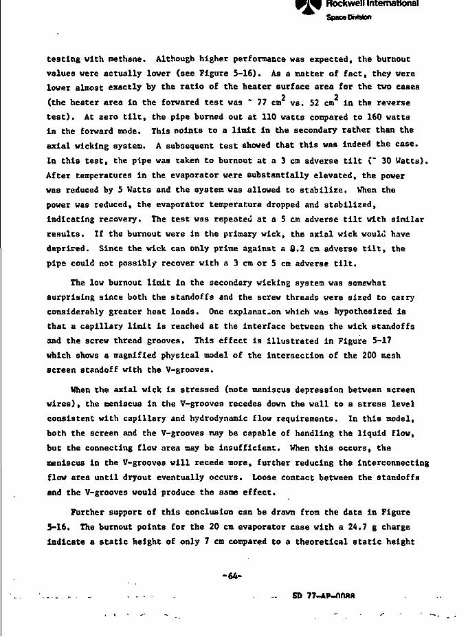
"I 1 J- 1 _». —.—_- - ... 4 — — - — — -• "1 - J i- I f - ••, mmr- - •> - -_,_- t."fe-
\
ft
\
Rockwell InternationalSpace OMston
/ Is -
testing with methane. Although higher performance was expected, the burnout
values were actually lower (see Figure 5-16). As a natter of fact, they werelower almost exactly by the ratio of the heater surface area for the two cases
2 2(the heater area in the forwared test was ~ 77 cm vs. 52 cm in the reverse
test). At zero tilt, the pipe burned out at 110 watts compared to 160 wattsin the forward mode. This points to a limit in the secondary rather than the
axial wlcking system. A subsequent test showed that this was indeed the case.
In this test, the pipe was taken to burnout at a 3 cm adverse tilt (~ 30 Watts).
After temperatures in the evaporator were substantially elevated, the power
was reduced by 5 Watts and the system was allowed to stabilize. When the
power was reduced, the evaporator temperature dropped and stabilized,
indicating recovery. The test was repeated at a 5 cm adverse tilt with similar
results. If the burnout were in the primary wick, the axial wick would have
deprired. Since the wick can only prime against a 0.2 cm adverse tilt, the
pipe could not possibly recover with a 3 cm or 5 cm adverse tilt.
The low burnout limit in the secondary wicking system was somewhat
surprising since both the standoffs and the screw threads were sized to carry
considerably greater heat loads. One explanation which was hypothesized is
that a capillary limit is reached at the interface between the wick standoffs
and the screw thread grooves. This effect is illustrated in Figure 5-17
which shows a magnified physical model of the intersection of the 200 t&esh
screen standoff with the V-grooves.
When the axial wick is stressed (note meniscus depression between screen
wires), the meniscus in the V-grooves recedes down the wall to a stress level
consistent with capillary and hydrodynamic flow requirements. In this model,
both the screen and the V-grooves may be capable of handling the liquid flow,
but the connecting flow area may be insufficient. When this occurs, the
meniscus in the V-grooves will recede more, further reducing the interconnecting
flow area until dryout eventually occurs. Loose contact between the standoffs
and the V-grooves would produce the same effect.
Further support of this conclusion can be drawn from the data in Figure
5-16. The burnout points for the 20 cm evaporator case with a 24.7 g charge
indicate a static height of only 7 en compared to a theoretical static height
-64-
SD 77-AP-nrutt
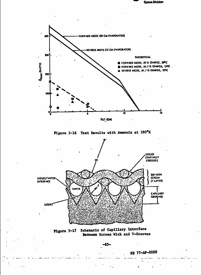
Rockwell Internationa)SpacoDMslon
400 FORWARD MODE 00 CM EVAPORATOR)
REVERSE MOPE (IS CM EVAPORATOR)
THEORETICAL
• FORWARD MODE, 21C O4AACE,• FORWARD MOW, 14.7 O CHAICI, UK
REVERSE MODE. 14.7 O CHARGE. UK
TaTtCM)
Figure 5-16 Test Results with Ananonla at 280*K
UOUD/VAPOJINTERFACE
UQU3
UQU10(PARTIALLYSTRESSED)
100 MESHSCREEN(I LAYER)
CA/ILLARYGROOVES
Figure 5-17 Schematic of Capillary InterfaceBetween Screen Hick and V-Groovea
1
4•}
SB 77-AP-0088
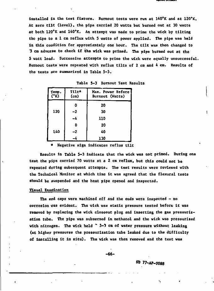
Rockwell InternationalSpace Ohnion
installed In the test fixture. Burnout tests were run at 140°K and at 120°K.
At zero tilt (level), the pipe carried 20 watts but burned out at 30 watts
at both 120°K and 140°K. An attempt was made to prime the wick by tilting
the pipe to a 1 cm reflux with 5 watts of power applied. The pipe was held
in this condition for approxiamtely one hour. The tilt was then changed to"3 cm adverse to check If the wick was primed. The pipe burned out at the
5 watt load. Successive attempts to prime the wick were equally unsuccessful.
Burnout tests were repeated with reflux tilts of 2 cm and 4 cm. Results of
the tests are summarized in Table 5-3.
Table 5-3 Burnout Test Results
Temp.<°K)
120
140
Tilt*(cm)
0-2
-4
0
-2
-4
Max. Power BeforeBurnout (Watts)
20
30
110
20
40
130
* Negative sign Indicates reflux tilt
Results in Table 5-3 indicate that the wick was not primed. During one
test the pipe carried 70 watts at a 2 cm reflux, but this could not be
repeated during subsequent attempts. The test results were reviewed with
the Technical Monitor at which time it was agreed that the flexural tests
should be suspended and the heat pipe opened and inspected.
Visual Examination
The end caps were machined off and the ends were Inspected - no
corrosion was evident. The wick waa static pressure tested before it was
removed by replacing the wick closeout plug and inserting Che gas pressuriz-
ation tube. The pipe was submersed in methanol and the wick was pressurised
with nitrogen. The wick held " 5-3 cm of water pressure without leaking
(at higher pressures the pressurization tube leaked due to the difficulty
of Installing it In situ). The wick was then removed and the test was
-66-
77-AP-0088
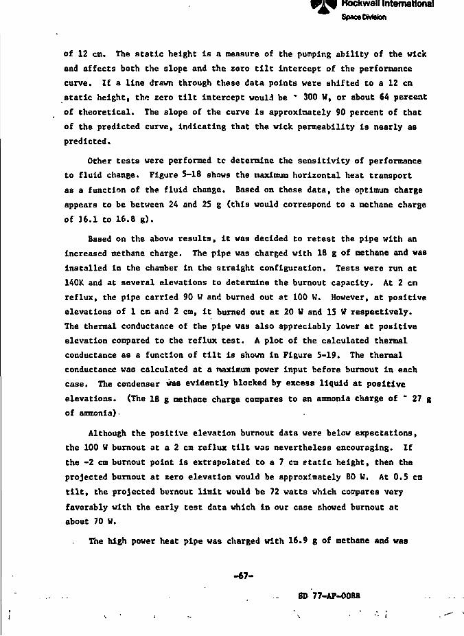
ETC
Rockwell InternationalSpace DMoton
of 12 cm. The static height is a measure of the pumping ability of the wick
and affects both the slope and the zero tilt intercept of the performance
curve. If a line drawn through these data points were shifted to a 12 cm
static height, the zero tilt intercept would be * 300 W, or about 64 percent
of theoretical. The slope of the curve is approximately 90 percent of that
of the predicted curve, indicating that the wick permeability is nearly as
predicted.
Other tests were performed tc determine the sensitivity of performance
to fluid change. Figure 5-18 shows the maximum horizontal heat transport
as a function of the fluid change. Based on these data, the optimum charge
appears to be between 24 and 25 g (this would correspond to a methane charge
of 16.1 to 16.8 g).
Based on the above results, it was decided to retest the pipe with an
increased methane charge. The pipe was charged with 18 g of methane and was
Installed in the chamber in the straight configuration. Tests were run at
140K and at several elevations to determine the burnout capacity. At 2 cm
reflux, the pipe carried 90 U and burned out at 100 W. However, at positive
elevations of 1 cm and 2 cm, it burned out at 20 W and 15 U respectively.
The thermal conductance of the pipe was also appreciably lower at positive
elevation compared to the reflux test. A plot of the calculated thermal
conductance as a function of tilt is shown in Figure 5-19. The thermal
conductance was calculated at a maximum power input before burnout in eachcase. The condenser was evidently blocked by excess liquid at positive
elevations. (The 18 g methane charge compares to an ammonia charge of * 27 g
of ammonia) •
Although the positive elevation burnout data were below expectations,
the 100 W burnout at a 2 cm reflux tilt was nevertheless encouraging. If
the -2 cm burnout point is extrapolated to a 7 cm etatlc height, then the
projected burnout at zero elevation would be approximately 80 W. At 0.5 cm
tilt, the projected burnout limit would be 72 watts which compares very
favorably with the early test data which in our case showed burnout at
about 70 W.
The high power heat pipe was charged with 16.9 g of methane and was
.(!
"!;'.
H
t 4
I
ff *
-67-
8D 77-AP-008S
\ .-.
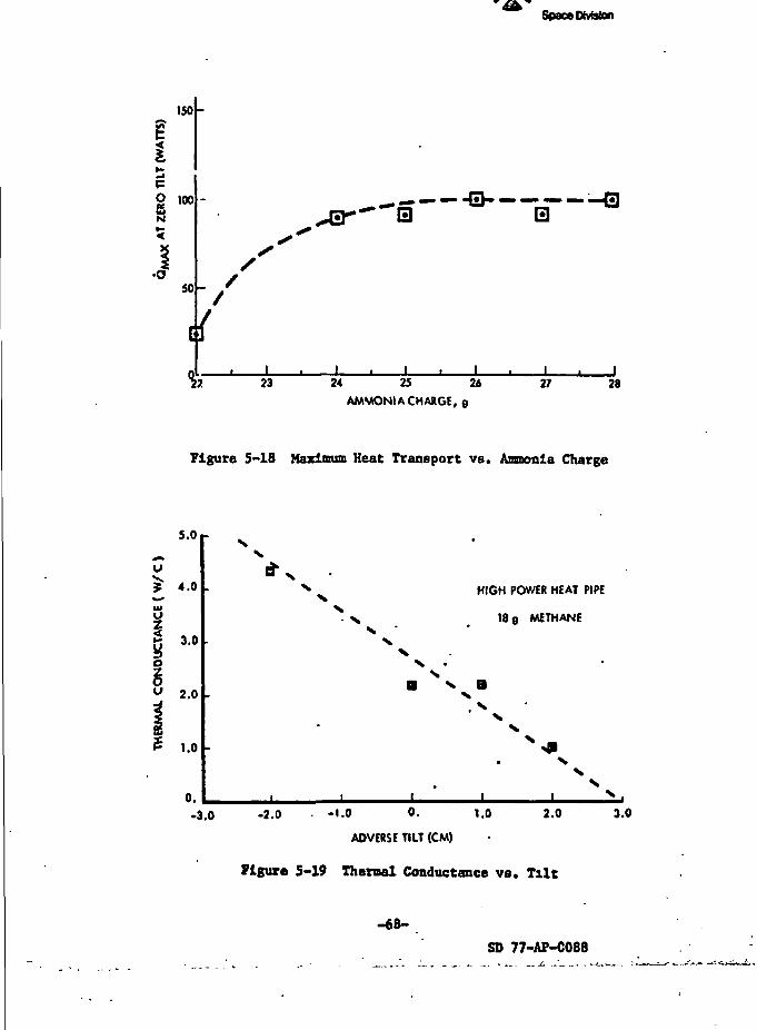
Rockwell InternationalSpace Division
ISO
-
O 100UlN
•oso
^ 13 ;
_L*22 23 24 25 26
AMMONIA CHARGE, 9
27 28
Figure 5-18 Maximum Heat Transport vs. Ammonia Charge
5.0
4.0
§ 3'°
I2.0
1.0
0.-3.0
x 'x
HIGH POWER HEAT PIPE
18 g METHANE
x aX. X
-2.0 -1.0 0. 1.0
ADVERSE TILT (CM)
2.0 3.0
Figure 5-19 Thermal Conductance vs. Tilt
-68-
SD 77-AF-C088
Rockwell InternationalSpace DMston
repeated. The wick held a mlnlnum of 5.6 en (2.2 In) of water. This
corresponds to a capillary radius of 8.3 x 10~ cm which is equivalent to
approximately 80 percent of 200 inch pumping. This is approximately the same
level to which the wick was qualified before it was installed in the pipe,
hence there was no degradation in static capillary pressure.
Inspection of the wick showed no signs of corrosion - the screen was
clean and bright except at the very ends of the standoffs where the screen
had discolored c'ue to high temperature during welding of the end caps.
EVALUATION
In both the ammonia tests as well as the irethane tests, the achieved
burnout values were one-third or less of the theoretically predicted values.
The single exception to this was the 67 watt burncut point at 140°K and 0.5 cm
adverse tilt with methane (approximately 70 percent of theoretical)„
Ammonia tests results seem to indicate that the wick was at least partially
primed, and that the acrew thread grooves may have been limiting. In general,
Che methane test data indicate that the wick was not primed. This was most
probably due to the presence of a non-condensible gas such as nitrogen which
was a substantial impurity in the" methane supply. Pressure depriming has
also been considered as a possibility. The open tunnel in the composite wick
may be causing the problem if pressure depriming is the answer.
-69-
j=1- *
en
•1
FAUtf BUAMJk MOT *'JUIUftRockwell International3paceD*fefcn
1 1
6.0 LOW TEMPERATURE HEAT PIPE FABRICATION AND TEST
The lew temperature heat pipe was fabricated in the same manner as the
high power Loat pipe, except that the design of the wick standoffs in the
evaporator was changed based on the test results of the high power pipe.
Results of the fabrication and test program are sunmarized in the following
text.
HEAT PIPE FABRICATION
The low temperature heat pipe was fabricated in accordance with the draw-
ing in Figure 6-1. The primary difference between it and the high power-heat pipe are (1) the flexible hose diameter is reduced to 0.64 cm (1/4 in)
to provide greater flexibility; (2) the diameter of the evaporator and
condenser sections are smaller; (3) the wick uses 54 mesh screen internally
and 250 mesh externally; and (4) the standoff bridges in the evaporator are
changed to a four element web design as shown in Figure 6-1. This dzsign
was felt to provide better communication and a greater interconnecting flow
area between the standoffs and the screwthread grooves. The fabrication
sequence and procedures were identical to those for the high power heat pipe
(Figure 5-2).
Flexible Container
The flexible container was purchased as an integral unit with schedule
80 stainless steel tubes welded to the bellows. The geometry of the flexible
container is shown in Figure 5-3. One flexible hose assembly was burst testedo
and failed in the bellows at a pressure of 1.14 x 10 Pa (16,500 psi). This is
over four times the estimated containment pressure at 315°K (2.4 x 10^ Pa -
3500 psi). However, the yield point of the bellows is 2.76 x 10⁷ Pa
(4000 psi), which means that if the pipe were proof tested to 1.5 times the
working pressure, permanent yield would occur in the bellows. To avoid this,
a 75 cm3 reservoir was attached to the end of the pipe prior to filling (see
BAKEOUT AND FILLING).
The evaporator and condenser sections were drilled and honed to an
-71-
i
J\K,4
M
SD 77-AP-0088
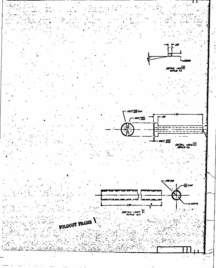
I
l_
. ' . . . • • • > "•• I.
;
,ft •
fOU*1
* - L '' ~ '
. - . : . * * ; ^ , - - . > - .
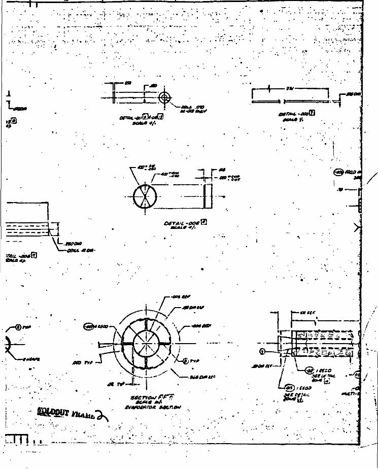
^ »
13r«K
t:, JiriH^TI
**
3i.00
secrto*/?•?!>
, , ^. ^
1
>
«•»•J/ ^
r(toa
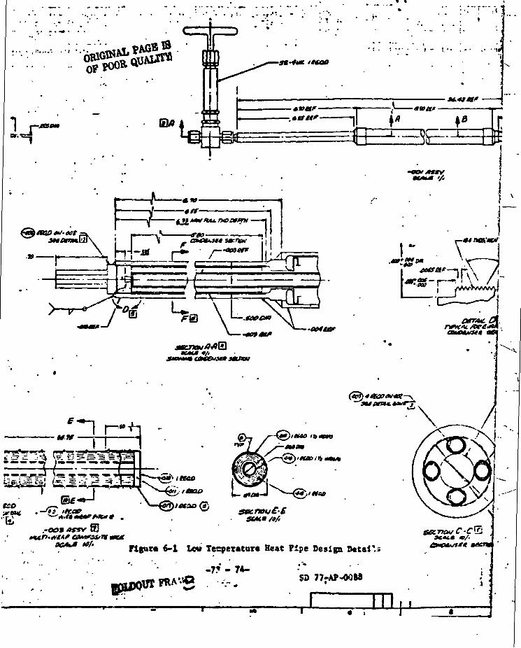
6-1 Low Tecperaturt Beat Pipe Design total's
.7* . 74-Q SD 77-AP-0088
1 HI0 1
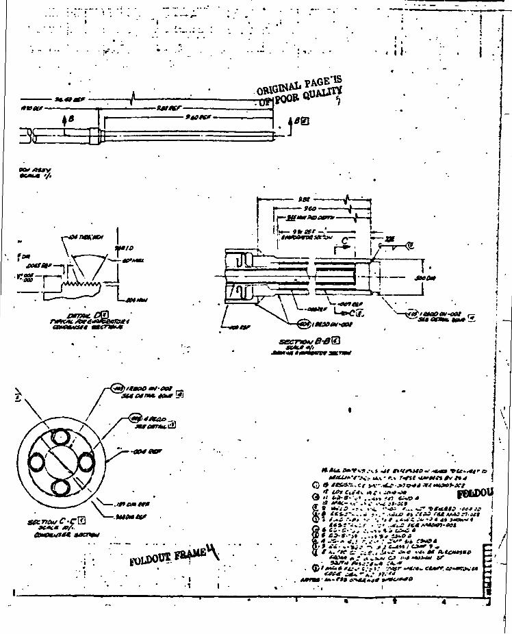
I - • - I - I
<*»«?- -A- tfffff-9tOfff-
OBIGrtff
. \ \ .
\ T'°f" X •/-£»•eoaetf—* r-\ / I.eg-^rvv / I*** ! , i _ \ '
G*
.
' I- *(J) I
.«> .'/A?
> A.- ««»;• •% ,/A-'fi.- .-Cff...
*«>»«<».- ,,.a' ^S* 0 «'rf. «f A.t£M+)*0
sr
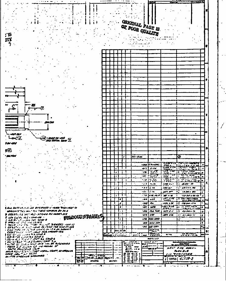
- • . - I
-I'-'r t i i t
•/is« .
01 Mv~<£>
'.-«.* •
,.4»» MI te-
.' »* •tffttn t* t» 4
•00*33
;..-.>*« ««•»<«f V •• * £*** **• ~-*.t f C*H*i C3V ».«»
>• 1 : • '
\t
'I !\ >
U>.oA»:Lr.'.-'.-' -r-
i .«« i .-«•».-
.. (•-•*-•• ***
. n» .•«*•
Ctil f-t •-• t
«I!
.**• tftrrartMef""*'f*'*f'af
% _
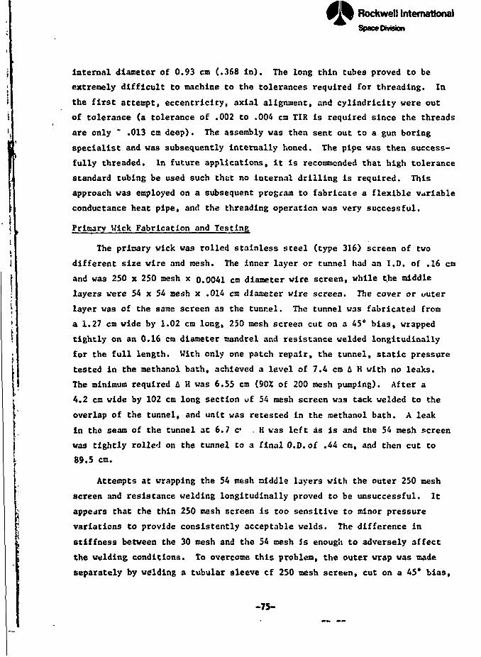
. i !..
Rockwell InternationalSpace Division
Internal diameter of 0.93 cm (.368 in). The long thin tubes proved to be
extremely difficult to machine to the tolerances required for threading. In
the first attempt, eccentricity, axial alignment, and cylindricity were out
of tolerance (a tolerance of .002 to .004 cm TIR is required since the threads
are only ~ .013 cm deep). The assembly vas then sent out to a gun boring
specialist and was subsequently Internally honed. The pipe was then success*
fully threaded. In future applications, it is recommended that high tolerance
standard tubing be used such that no internal drilling is required. This
approach was employed on a subsequent program to fabricate a flexible variable
conductance heat pipe, and the threading operation was very successful.
Primary Wick Fabrication and Testing
The primary wick was rolled stainless steel (type 316) screen of two
different size wire and mesh. The inner layer or tunnel had an I.D. of .16 cm
and was 250 x 250 mesh x 0.0041 cm diameter wire screen, while t.he middle
layers were 54 x 54 mesh x .014 cm diameter wire screen. The cover or outer
layer was of the saraa screen as the tunnel. The tunnel was fabricated from
a 1.27 cm wide by 1.02 cm long, 250 mesh screen cut on a 45° bias, wrapped
tightly on an 0.16 cm diameter mandrel and resistance welded longitudinally
for the full length. With only one patch repair, the tunnel, static pressure
tested in the methanol bath, achieved a level of 7.4 cm & H with no leaks.
The minimum required A H was 6.55 cm (90% of 200 mesh pumping). After a
4.2 cm wide by 102 cm long section of 54 mesh screen was tack welded to the
overlap of the tunnel, and unit was retested in the methanol bath. A leak
in the seam of the tunnel at 6.7 c* . H vas left as is and the 54 mesh screen
was tightly rolled on the tunnel to a final O.D. of .44 cm, and then cut to
i 89.5 cm.
Attempts at wrapping the 54 jnesh middle layers with the outer 250 mesh
screen and resistance welding longitudinally proved to be unsuccessful. It
appears that the thin 250 mesh screen is too sensitive to minor pressure
variations to provide consistently acceptable welds. The difference in
stiffness between the 30 mesh and the 54 mesh is enough to adversely affect
the welding conditions. To overcome this problem, the outer wrap was made
separately by welding a tubular sleeve cf 250 mesh screen, cut on a 45* bias,
-75-
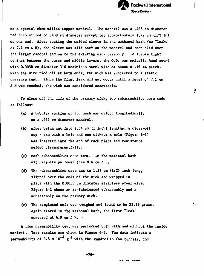
J . — J. ..,-J,
Rockwell InternationalSpace Division
on a special chem milled copper mandrel. The mandrel was a .465 cm diameter
rod chem milled to .439 cm diameter except for approximately 1.27 cm (1/2 in)
on one end. After testing the welded sleeve in the mcthanol bath (no "leaks"
at 7.4 cm A H), the sleeve was slid bach on the mandrel and then slid over
the larger mandrel 2nd on to the existing wick assembly. To insure tight
contact between the outer and middle layers, the O.D. was spirally hand wound
with 0.0058 cm diameter 316 stainless steel wire at about a .16 cm pitch.
With the wire tied off at both ends, the wick was subjected to a static
pressure test. Since the first leak did not occur until a level o' 7.1 cm
& H was reached, the wick was considered acceptable.
To close off the cndj of the primary wick, two subassemblies were made
as follows:
(a) A tubular section of 250 mesh was welded longitudinally
on a .439 cm diameter mandrel.
(b) After being cut into 2.54 ca (1 inch) lengths, a close-off
cap - one with a hole and one without a hole (Figure 6-1)
was Inserted into the end of each piece and resistance
welded circumferentially.
(c) Both subassemblies v -e tesL. xn the methanol bath
with results no lower than 8.6 cm A K.
(d) The subassemblies were cut to 1.27 cm (1/2) inch long,
slipped over the ends of the wick and wrapped in
place with the 0.0058 cm diameter stainless steel wire.
Figure 6-2 shows an as-fabricated subassembly and a
subassembly on the primary wick.
(e) The completed unit was weighed and found to be 23.98 grams.
Again tested in the methanol bath, the first "leak"
appeared at 6.9 cm L H. •
A flow permeability test was performed both with and without the inside
mandrel• Test results are shown in Figure 6-3. The data indicate a
permeability of 3.8 x 10* m with the nandrel in (no tunnel), and
-76-
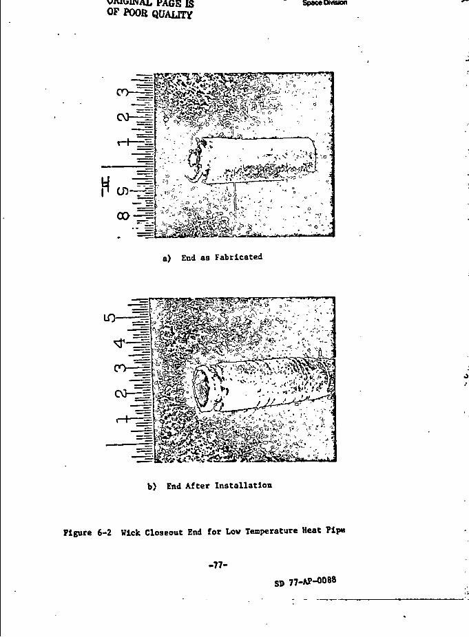
ORIGINAL PAGE ISOP POOR QUALITY
Rockwell International
Space Division
~" <-iri,T '/Jjl C-^Q £, - ,• T ™ -,^K>vsi'O--^SV*" <= & ^ >j- -TST vt CS>T4j c v ... . -
fit
a) End as Fabricated
ID 1==!
^ i y /i''ij £tf ? i
&*?£•$',**;"* '•>, »<< y •«*** '
b) End After Installation
Figure 6-2 Wick Closeout End for Lov Temperature Heat Pip*
-77-
77-AP-0088
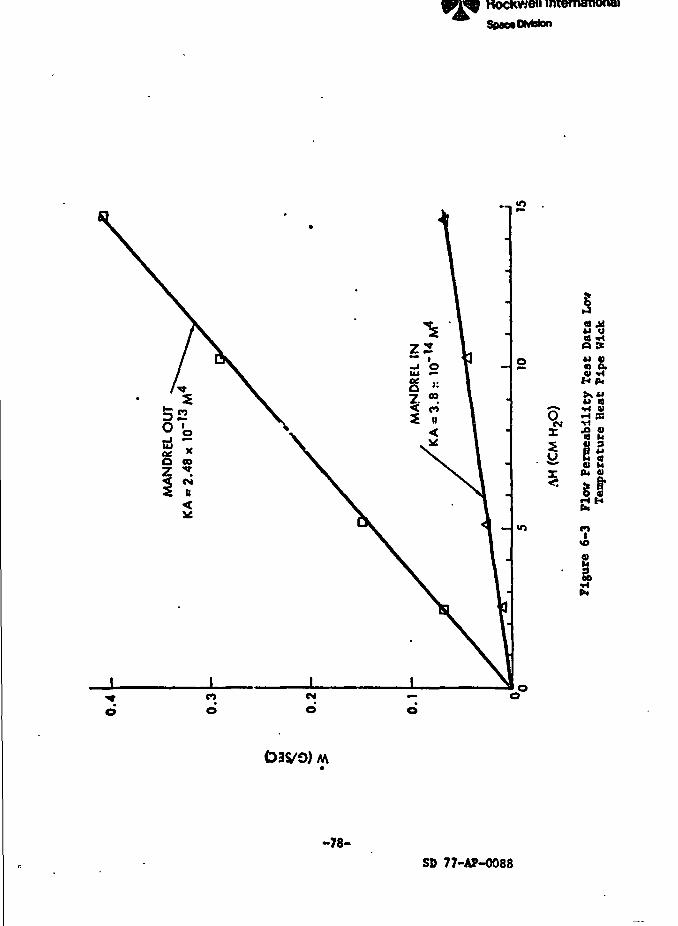
fRockwell IntematkNulSpacaOMston
5a,
a
«o
D3VO) M
-78-SD 77-AP-0088
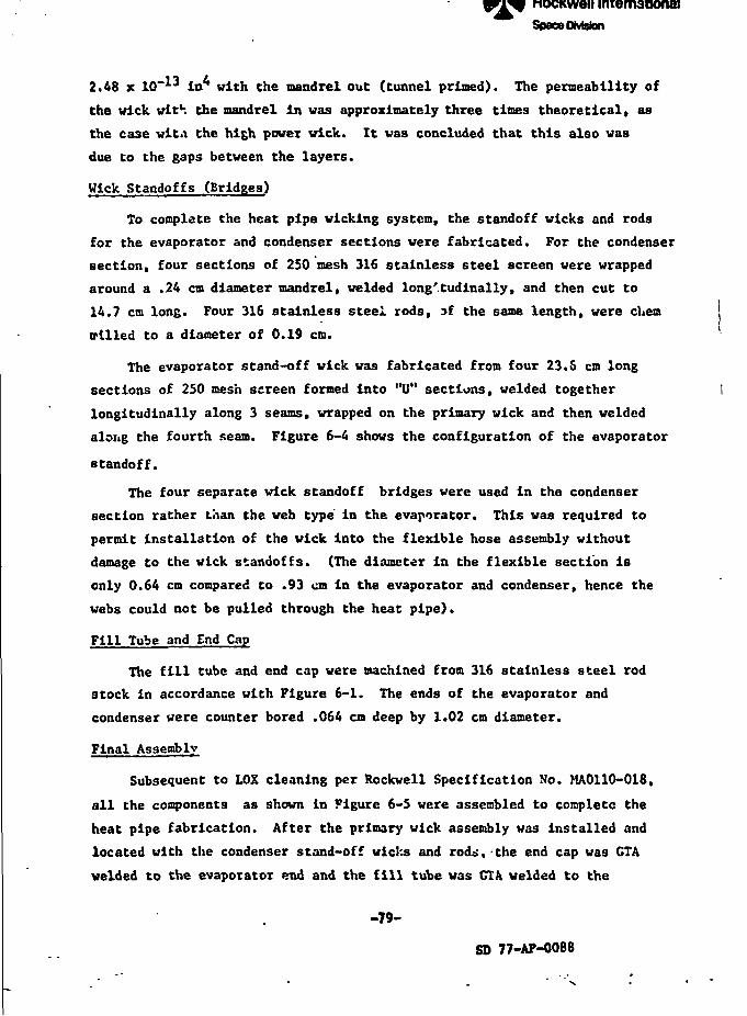
Rockwell InternationalSpace OMston
2.48 x 10~ 3 in* with Che mandrel out (tunnel primed). The permeability of
the wick with the mandrel in was approximately three times theoretical, aa
the case wita the high power wick. It was concluded that this also was
due to the gaps between the layers.
Wick Standoffs (Bridges)
To complete the heat pipe wicking system, the standoff wicks and rods
for the evaporator and condenser sections were fabricated. For the condenser
section, four sections of 250 mesh 316 stainless steel screen were wrapped
around a .24 cm diameter mandrel, welded longitudinally, and then cut to
14.7 cm long. Four 316 stainless steel rods, of the same length, were cl.em
trilled to a diameter of 0.19 cm.
The evaporator stand-off wick was fabricated from four 23.6 cm long
sections of 250 mesh screen formed into "U" sections, welded together
longitudinally along 3 seams, wrapped on the primary wick and then welded
along the fourth seam. Figure 6-4 shows the configuration of the evaporator
standoff.
The four separate wick standoff bridges were used in the condenser
section rather than the web type in the evaporator. This was required to
permit installation of the wick into the flexible hose assembly without
damage to the wick standoffs. (The diameter in the flexible section is
only 0.64 cm compared to .93 cm in the evaporator and condenser, hence the
webs could not be pulled through the heat pipe).
Fill Tube and End Cap
The fill tube and end cap were machined from 316 stainless steel rod
stock in accordance with Figure 6-1. The ends of the evaporator and
condenser were counter bored .064 cm deep by 1.02 cm diameter.
Final Assembly
Subsequent to LOX cleaning per Rockwell Specification No. MA0110-018,
all the components as shown in Figure 6-5 were assembled to complete the
heat pipe fabrication. After the primary wick assembly was installed and
located with the condenser stand-off wicks and rods, the end cap was CTA
welded to the evaporator end and the fill tube was CIA welded to the
V
-79-
SD 77-AP-0088
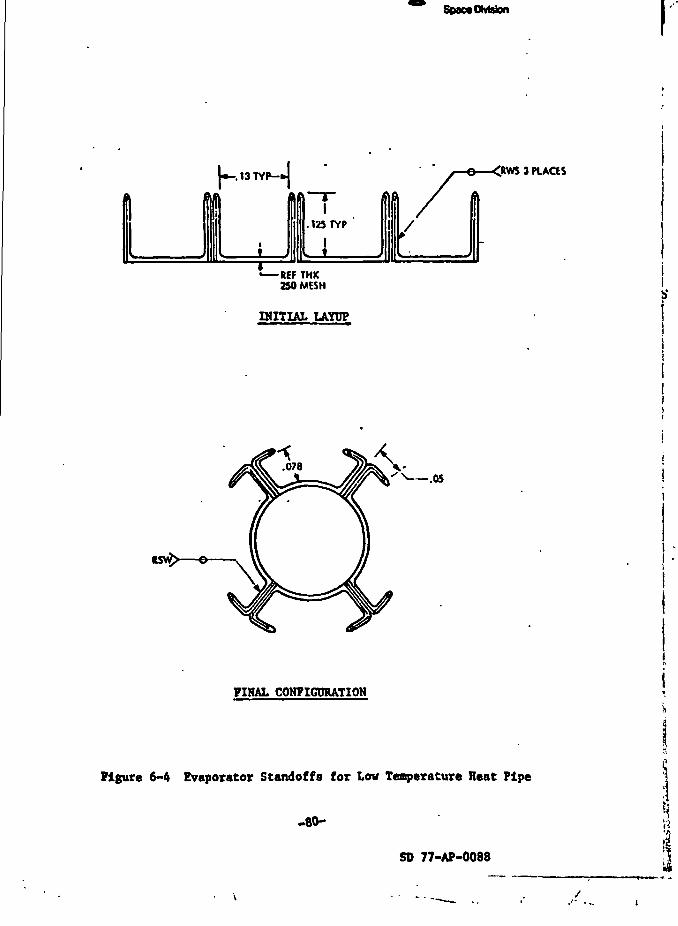
Rockwell InternationalSpaoaDMaton
-REF THK250 MESH
INITIAL LAYPP
3 PLACIS
-.'S-•"{
FIHAL CONFIGURATION
Figure 6-4 Evaporator Standoffs for Low Temperature Heat Pipe
-eo-Uii
SD 77-AP-0088
Rockwell InternationalSpace Division
f*^-.::"•*:•< S:KV&;• V .V:-i* £*?•£&^v^pit wv l*4.-'i-T.'**fe' >.?K1*-1"? 'Tl*-1^t-'-r ' ''~^
KS
ORIGINAL PAGE ISOF POOR QUALITY
SoI
'1*Rockwell International
Space OMstonf
I
evaporator end and the fill tube was GTA welded to the condenser end - bothwith 316 stainless steel filler alloy. The assembly was proof pressure tested
at 2.76 x 10⁷ Pa (4000 psig) and helium leak tested at 2.07 x 10⁷ Pa (3000
psig). This was followed by a recleaning to the HA0110-018 specification ' '9
BAKEOUT AND FILLING \ |»i •
The heat pipe was baked out and filled in the same manner as the high \ ^_
power pipe. Based on the final fill calculations, it was determined that 1
the pressure at 315°K could exceed the design value of 2.07 x 10⁷ Pa (3000 psi). |
Since the pipe was only proof tested to 2.76 x 10⁷ Pa, it was decided to add ]
a 75 cn>3 reservoir onto the condenser end of the pipe. This reduced the ; ',
expected pressure by about 30 percent and was acceptable. The reservoir was I
LOX cleaned before Installation. The final assembly is shown in Figure 6-6. 'I
Bakeout ' 'I
The heat pipe assembly was installed in the bakeout fixture and hocked ;
up to the high vacuum system. The pipe temperature was maintained at T.SOF
(121 C) for 18 hours and the vacuum was maintained below 10 micron after "
the initial decay. t
Filling j
The theoretical 100 percent fill charge for the oxygen based on an 80°K f
minimum operating temperature is 16.1 g including the vapor space in the ' '
pressure reservoir. The pipe was initially charged with 21.6 g of oxygen
to provide excess for venting. The vent line vas installed through the
vacuum chamber with a 1/8 in sa line to allow the hnat pipe tc be vented
during operation in the vacuum chamber.
TEST PROGRAM
Heater and thermocouple locations for the low temperature heat pipe are
shown in Figure 6-7. The pipe was installed in the test fixture shown in
Figure 6-8, leveled, and installed in the vacuum chamber.
Tests were conducted with oxygpn inventories ranging from 17-20 g to
provide sufficient cnarge for priming of the tunnel. The nominal operating
temperature vas 90 + 5°K. The heat pipe system vas wrapped with multi-layer
. . , - - - - ... . SD 77-AP-0088 |. J
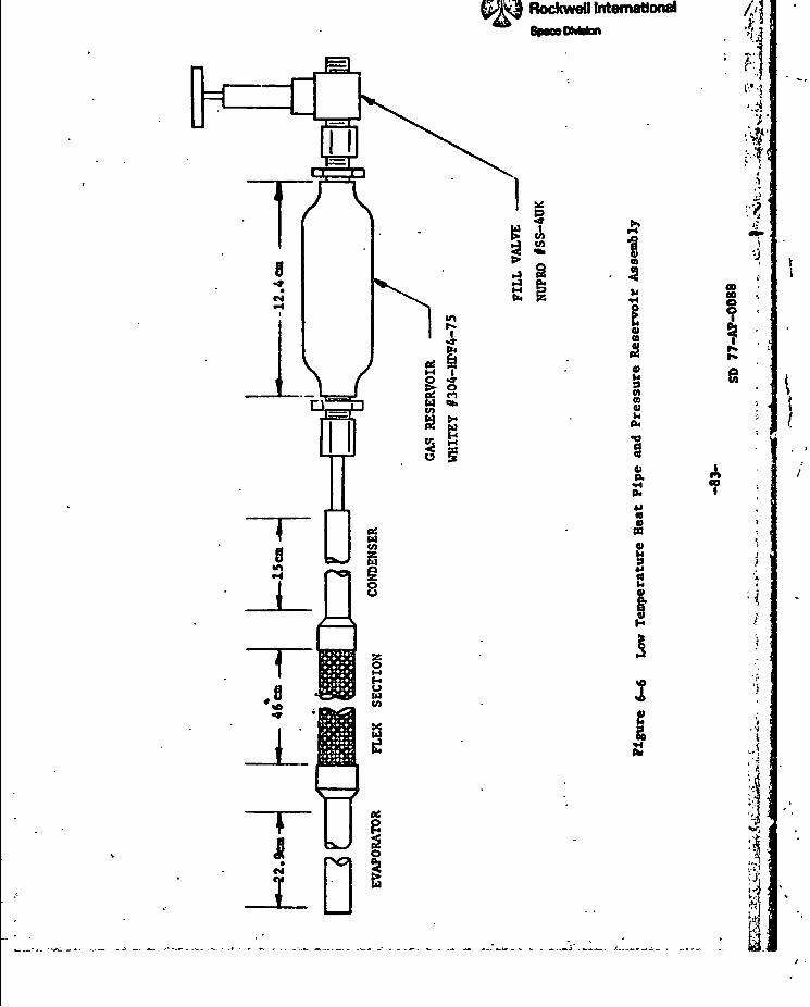
RockweO Internationa)SpcwOMaton
&«fcl0)aai
SL
2tl
S2
E3'
i
«
'
[
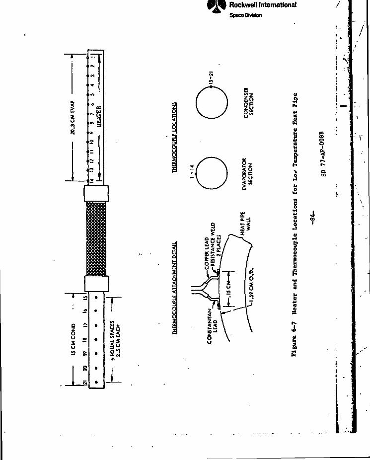
I a_ 1 -
Rockwell InternationalSpace OMtion
<§
§5tu
\
01o.
iaM
H
3
3pHi
1Si
I
goCOo
oWl
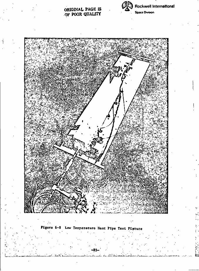
ORIGINAL PAGE ISOF POOR QUALITY
Rockwell InternationalSpace Division
.1
) '*'
t
is6
Figure 6-8 Low Temperature Heat Pipe Test Fixture
-85-
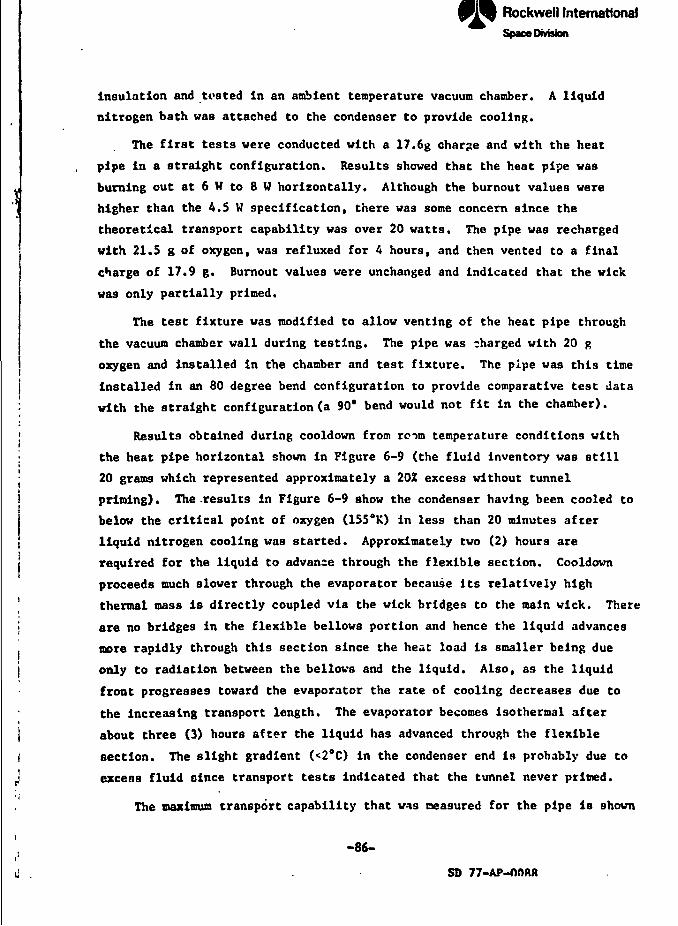
L.Rockwell InternationalSpace Division
insulation and trated in an ambient temperature vacuum chamber. A liquid
nitrogen bath was attached to the condenser to provide cooling.
The first tests were conducted with a 17.6g charge and with the heat
pipe in a straight configuration. Results showed that the heat pipe was
burning out at 6 H to 8 W horizontally. Although the burnout values were
higher than the 4.5 W specification, there was some concern since the
theoretical transport capability was over 20 watts. The pipe was recharged
with 21.5 g of oxygen, was refluxed for 4 hours, and then vented to a final
charge of 17.9 g. Burnout values were unchanged and indicated that the wick
was only partially primed.
The test fixture was modified to allow venting of the heat pipe through
the vacuum chamber wall during testing. The pipe was charged with 20 g
oxygen and installed in the chamber and test fixture. The pipe was this time
| installed in an 80 degree bend configuration to provide comparative test data
: with the straight configuration (a 90° bend would not fit in the chamber).
I Results obtained during cooldown from room temperature conditions with
• the heat pipe horizontal shown in Figure 6-9 (the fluid inventory was still
20 grams which represented approximately a 20Z excess without tunnel
! priming). The .results in Figure 6-9 show the condenser having been cooled to
below the critical point of oxygen (155°K) in less than 20 minutes afcer
liquid nitrogen cooling was started. Approximately two (2) hours are
j required for the liquid to advance through the flexible section. Cooldown
proceeds much slower through the evaporator because its relatively high1 thermal mass is directly coupled via the wick bridges to the main wick. There
j are no bridges in the flexible bellows portion and hence the liquid advances
more rapidly through this section since the heac load is smaller being due
j only to radiation between the bellows and the liquid. Also, as the liquid
front progresses toward the evaporator the rate of cooling decreases due to
the increasing transport length. The evaporator becomes isothermal after
! about three (3) hours after the liquid has advanced through the flexible
I section. The slight gradient (<2°C) in the condenser end is probably due to
j excess fluid oince transport tests indicated that the tunnel never primed.
The maximum transport capability that was measured for the pipe is shown
' -86-
i j . s o 77-Ap-nnftft
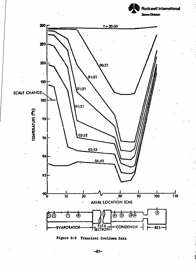
;i_L_J L L_.*a_:__i:_--.*
SCALE CHANGE
3 96 -
92 -
90.10
Rockwell International
Space OMstan
20 ^ 80 90»
AXIAL LOCATION (CM)
in w
-EVAPORATOR-
100 110
nACTION
Figure 6-9 Transient Cooldown Data
-87-
DNDENSER -
' 1
«t
\
~/
l~~-,.~al:. ».l-.4.» m±*
Rockwell InternationalSpacvOimion
in Figure 6-10 versus heat pipe elevation. Also shown is the theoretical
performance for an open trtery and for a closed artery without a primed tunnel.
Nominal operating conditiors are 90*K. It should be noted that "0-g"
equivalent performance corresponds to operation at an elevation which is
equal to half the diameter of the main wick (in this case, 0.5 D - 0.23 cm).
At a horizontal elevation the wick must pump against gravity across its
diameter and the transport capability will be less than what would be obtained
in "0-g".
The extrapolated "0-g" transport for the straight configuration is 7.8
watts which is 42% better than predicted tor the open artery but only 30Z of
the closed artery's capability. The transport with the 80* bend appears to
be slightly below that of the straight configuration.
The static height for a concentric wick is given by
hs '
where
h - Heat pipe elevation where the heat load is zeroo
t. • Thickness of the wick bridge between the tubewall and the main wick
An examination of the data sht.ws that the static height extrapolated from
the measured data is twice that which can be obtained with the coarse nesh
screen, but only 44X of the theoretical for the 2SO mesh outer layer. Since
the static height is equal to the maximum capillary pumping head, these
results would indicate that composite pumping which is twice that of the open
artery and about half the theoretical maximum has been achieved. This in turn
implies that the "0-g" extrapolation should also be a factor of two better than
that of the open artery. The f.-.ct that the equivalent "0-g" performance is
only 42X better means that the flow losses are greater than predicted. The
higher losses could be attributed to lower liquid flow conductance (KA), higher
vapor losses which axe perhaps due to perturbations in the flexible section,
cr inadequate flow within the circumferential screw thread grooves. Perfor-
mance at higher evaporator heat fluxes is essentailly the same which would
eliminate the grooves as a performance limit. The increased performance
r /
i-88-
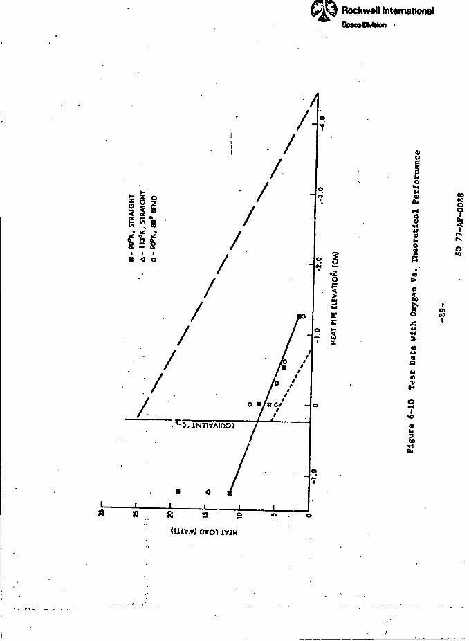
Rockwell InternationalSfcanDMaton •
s
2
«o
g>2
J
eoooo
Ito
Io\to
iV3H
•~3
as
M I;'T/
) I. ..-.i.,... iRockwell InternationalSpace Division
(14.5 W) obtained at a 1.27 cm positive orientation and at an operating
temperature of 113°K vouid indicate that vapor losses may be causing the
reduction. However, the same oerformance was also obtained at 90°K with the
80° bend. In addition, 19 U transport was also measured at this elevation
at 90°K with the straight pipe which would indicate that the degree of
arterial priming could be a variable. Hence <t would seem that the reduced
performance can be attributed to incomplete priming of the arterial wick and
to a reduction of the liquid flow conductance over what was measured for the
wick when it was tested before insertion into the pipe.
The lower-than-theoretical burnout data may be due to pressure depriming
of the composite, or to a non-condensible gas bubble in the wick which Units
the realizable capiJM'.-y head to less than 200 or 250 i*esh pumping. In
hopes of determining which of these two it might be, two additional tests
vere performed. First, the pipe was tested with methanol which has a Inw
vapor pressure, and then with a special ultra-high purity grade of oxygen to
minimize any trace contaminants of non-condensible gases. No improvement was
observed in either test, but the gas bubble hypothesis does appear to be the
most reasonable explanation. The high solubility of cryogenic fluids to other
non-condensible gases (e.g., methane/nitrogen) makes purification and out-
gassing very difficult.
-SO-
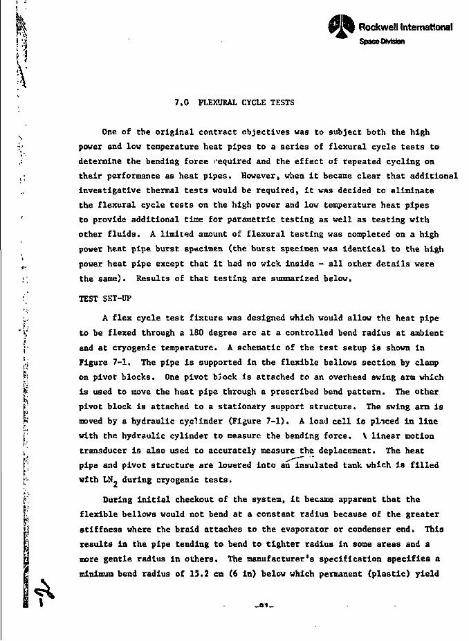
i I*jRockwell InternationalSpace DMston
7.0 FLEXURAL CYCLE TESTS
One of the original contract objectives was to subject both the high
' power and low temperature heat pipes to a series of flexural cycle tests toJ. determine the bending force required and the effect of repeated cycling on
,; their performance as heat pipes. However, when it became clear that additional
investigative thermal tests would be required, it was decided to eliminate
the flexural cycle tests on the high power and low temperature heat pipes
to provide additional time for parametric testing as well as testing with
other fluids. A limited amount of flexural testing was completed on a high
power heat pipe burst specimen (the burst specimen was identical to the high
t. power heat pipe except that it had no wick inside - all other details were
;; the same). Results of that testing are summarized below.
:; TEST SET-UP
u A flex cycle test fixture was designed which would allow the heat pipe
' ij to be flexed through a 180 degree arc at a controlled bend radius at ambient
J" and at cryogenic temperature. A schematic of the test setup is shown in
'.; Figure 7-1. The pipe is supported in the flexible bellows section by clamp• *.
fc on pivot blocks. One pivot bJock is attached to an overhead swing arm which
t: is used to move the heat pipe through a prescribed bend pattern. The other
r pivot block is attached to a stationary support structure. The swing arm is
?«' moved by a hydraulic cycl inder (Figure 7-1). A load cell is placed in line
I with the hydraulic cylinder to measure the bending force. \ linear motion
i' transducer is also used to accurately measure the deplacement. The heat
[; pipe and pivot structure are lowered into an insulated tank which is filled
['- with LN. during cryogenic tests.
f-; During initial checkout of the system, it became apparent that theI1I- flexible bellows would not bend at a constant radius because of the greater
\ stiffness where the braid attaches to the evaporator or condenser end. This
results in the pipe tending to bend to tighter radius in some areas and a
more gentle radius in others. The manufacturer's specification specifies a
" minimum bend radius of 15.2 cm (6 in) below which permanent (plastic) yield
1
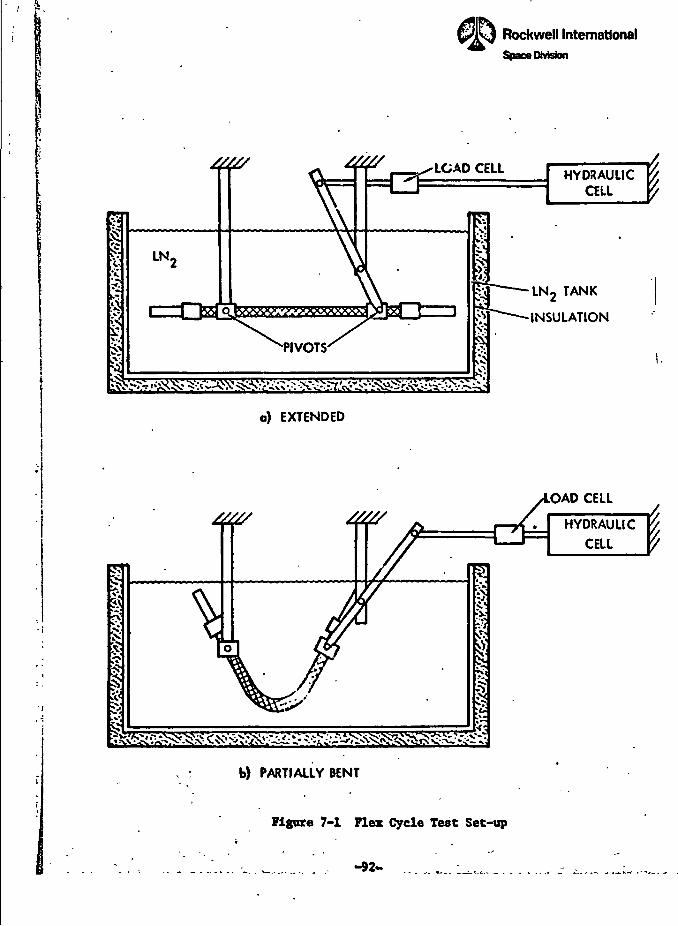
• .2V I I
r*cr^=.nWfs. 4 .xss.'WBsrs-.sw ra'»C33ri T»e»e«e= /» r
' ' V* C"'." ' J
Rockwell InternationalSpace Wvfeaon
a) EXTENDED
b) PARTIALLY BENT
Figure 7-1 Flex Cycle Test Set-up
-92-
HYDRAULICCELL
LN2 TANK
INSULATION
OAD CELL
HYDRAULIC
CELL
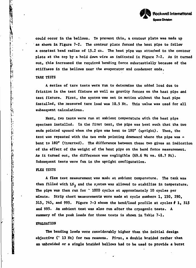
' ' XJ • » • \T::; \
i •
fa:f *•
* J -
[1I
l!
i
Rockwell Internationa!Space Division
could occur In the bellows. To prevent this, a contour plate was made up
as shown in Figure 7-2. The contour plate forced the heat pipe to follow
a constant bend radius of 15.2 ctr.. The heat pipe was attached to the contour
plate at the top by a hold down wire as indicated in Figure 7-2. As it turned
out, this increased the required bending force substantially because of the
stiffness in the bellows near the evaporator and condenser ends.
TARE TESTS
A series of tare tests were run to determine the added load due to
friction in the test fixture as well as gravity forces on the heat pipe and
test fixture. First, the system was set in motion without the heat pipe
installed, the measured tare load was 18.5 Nt. This value was used for all
subsequent calculations.
Next, two tests were run at ambient temperature with the heat pipe
specimen installed. In the first test, the pipe was bent such that the two
ends pointed upward when the pipe was bent to 180s (upright). Then, the
test was repeated with the two ends pointing downward where the pipe was -
bent to 180° (Inverted). The difference between these two gives an Indication
of the effect of the weight of the heat pipe on the bend force measurement.
As it turned out, the difference was negligible (69.6 Nt vs. 68.7 Nt).
Subsequent tests were fun in the upright configuration.
FLEX TESTS
A flex test measurement was madu at ambient temperature. The tank was
then filled with LN- and the system was allowed to stabilize in temperature.
The pipe was then run for * 1000 cycles at approximately 10 cycles per
minute. Strip chart measurements were made at cycle numbers 1, 150, 290,
515, 745, and 995. Figure 7-3 shows the bend/load profile at cycles* 1, 515
and 995. An ambient test was also run after the cryogenic tests. A
summary of the peak loads for these tests is shown in Table 7-1.
EVALUATION
The bending loads were considerably higher than the initial design
objective (* 13 Nt) for two reasons. First, a double braided rather than
an unbraided or a single braided bellows had to be used to provide a burst
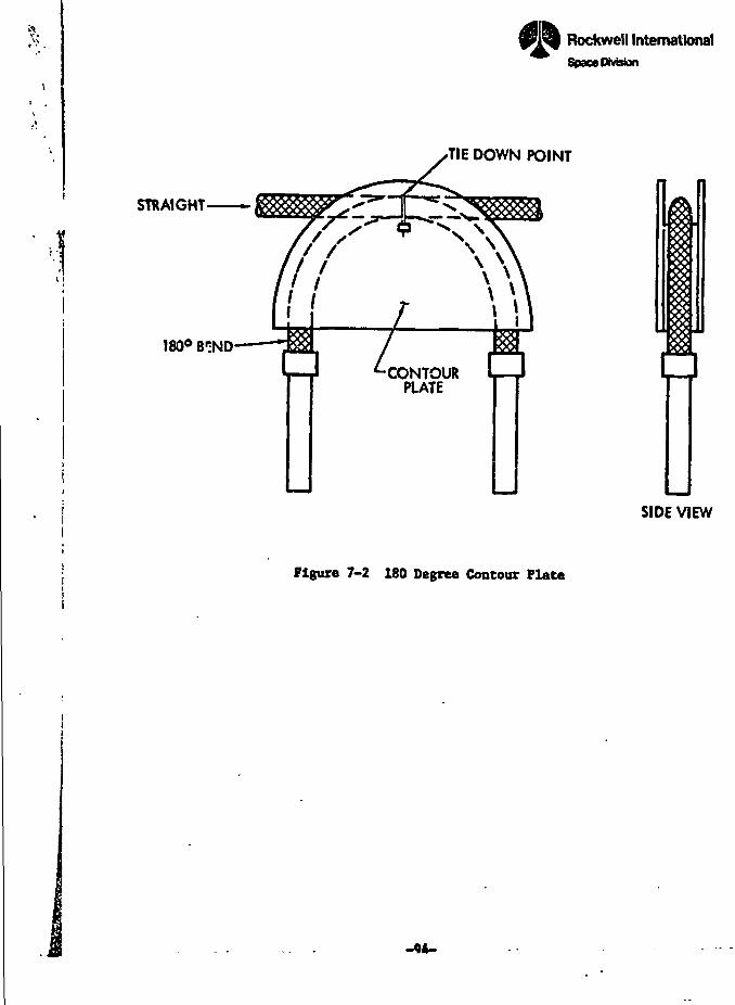
^
... . !fll-,- , .
' '• V** •
•1STRAIGHT
180° BIND
Rockwell InternationalSpace Division
TIE DOWN POINT
CONTOURPLATE
Figure 7-2 180 Degree Contour Plate
SIDE VIEW
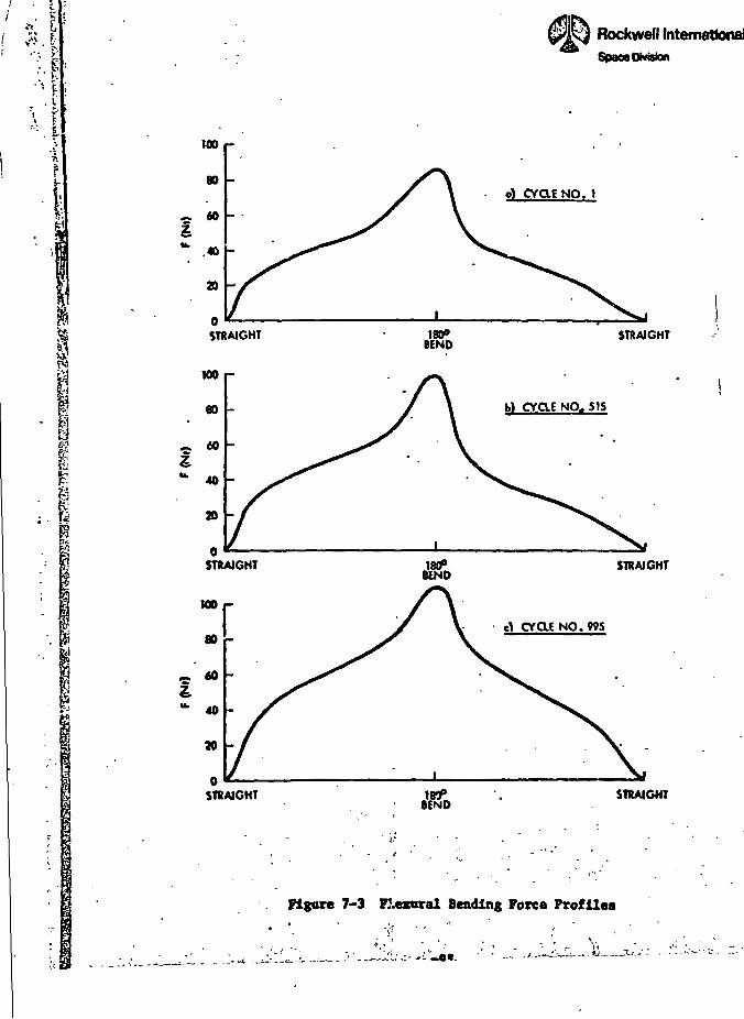
'•••$
\ "1:<. i
*f
«>»'8
£fcI•yl
!i
i
» • •
[:. v;: ,ri- 1 ,««ic»3e3*aS'?*'.r.r??SS3
100
80
~ toIfc .46
20
STRAIGHT
w»r
^ 60I
"• 40
20
STRAIGHT
Rockwell InternationalSpaoeOMskn
o) CYqg NO. 1
STRAIGHT
b) CVaE NO. 515
STRAIGHT
CyaENO.995
STRAIGHT
Figure 7-3 Pleraral Bending Force Profiles
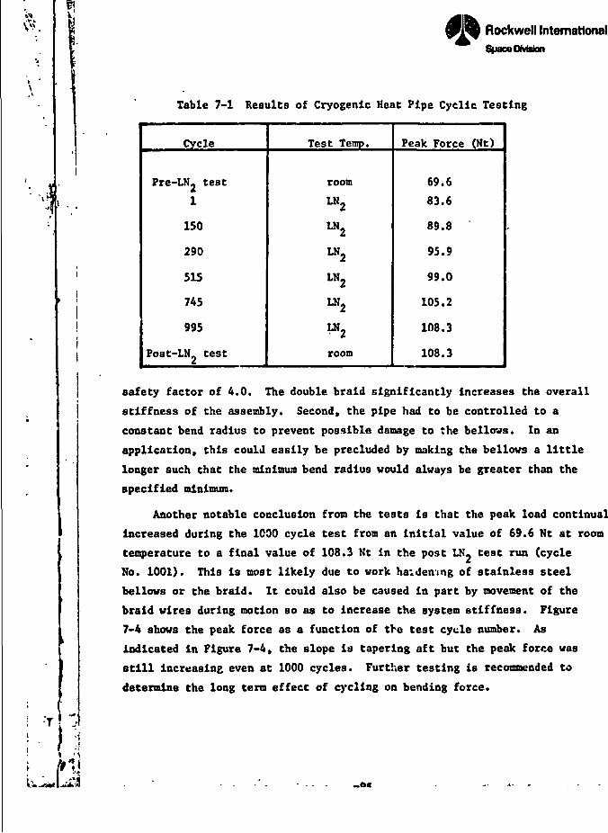
Rockwell InternationalSpace Division
Table 7-1 Results of Cryogenic Heat Pipe Cyclic Testing
Cycle
Pre-LN2 test
1
150
290
515
745
995
Post-LN test
Test Temp.
room
LN2
LN,
LN2
LN,
LN2
room
Peak Force (Nt)
69.6
83.6
89.8
95.9
99.0
105.2
108.3
108.3
safety factor of 4.0. The double braid significantly increases the overall
stiffness of the assembly. Second, the pipe had to be controlled to a
constant bend radius to prevent possible damage to the bellows. In an
application, this could easily be precluded by making the bellows a little
longer such that the minimum bend radius would always be greater than the
specified minimum.
Another notable conclusion from the tests is that the peak load continually
increased during the 1C90 cycle test from an initial value of 69.6 Nt at room
temperature to a final value of 108.3 Nt in the post LN- test run (cycle
No. 1001). This is most likely due to work haidenmg of stainless steel
bellows or the braid. It could also be caused in part by movement of the
braid wires during motion so as to increase the system stiffness. Figure
7-4 shows the peak force as a function of the test cycle number. As
indicated in Figure 7-4, the slope is tapering aft but the peak force was
still increasing even at 1000 cycles. Further testing is recommended to
determine the long term effect of cycling on bending force.
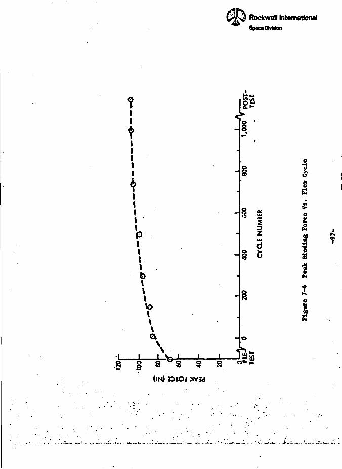
II
I '
PII\\0
IIto\\a
8 8
ON)
Space OMsfan
3
3
I
o&
S
•>* _
§ 8
sf/«r
p
5|
oM
* !•tt»• i
i]
5
< <
•>-f .
™u - i- _r_~ir>
nRockwell International
3pac*DMston
8.0 CONCLUSIONS ANC RECOMMEKDATIONS
GENERAL
The concept of a flexible cryogenic heat pipe has been demonstratedsuccessfully, although the ultimate performance capability of the spiral
\.
i>- DUltiwrap composite wicking system was never realized in either the high
''-' power (methane) or the low temperature (oxygen) heat pipe. The wicks were ,
r very flexible but the flexibility of the container was severely restricted ^
I by the double braided stainless steel bellows which was required for pressure j
|" safety. Notwithstanding the difficulties which were encountered, the pipes ,}
I successfully demonstrated the concept of flexible cryogenic heat pipes over ' j
* a range of temoerature, and the demonstrated performance levels are ,
:• sufficient for many potential space applications. Additional research in *;. the area of composite and artery wicks vlth cryogenic (as well as ambient) •
;; temperature fluids is strongly recommended since it affects not only <
;-- flexible heat piped, but also rigid heat pipes and especially gas controlled '
'! heat pipes.
FLEXIBILITY
The bias-wrapped spiral screen wick design provided excellent flexibility.
The wick can be bent to a very sull bend radius (1 or 2 em) and flexed
R repeatedly without damage. The flexibility of the system was limited by the
flexible bellows container. Because of the high contamlnent pressure
associated with cryogenic fluids, and the requirement for a pressure safety
factor of at least ».0, the bellows had to be double braided which signific-
antly increased the bending stress. The flexural cycling test program was
not performed, however, because it was felt that the thermal test program
was more demanding.
The high temperature heat pipe «sed nonlnal 3/8 in (.95 en) flexible
hose and had a Hnii"™ bend radius of 15.2 cm coopered to a specification
of 20 cm. The bending force was measured on a burst test facsimile
of the high power heat pipe. The bending force at a 180 degree bend angle
van initially * 70 Ht and Increased to 108 Nt after 1000 cycles. Although
-99- FWKWWO PAGE BUKK NOT nrif*»
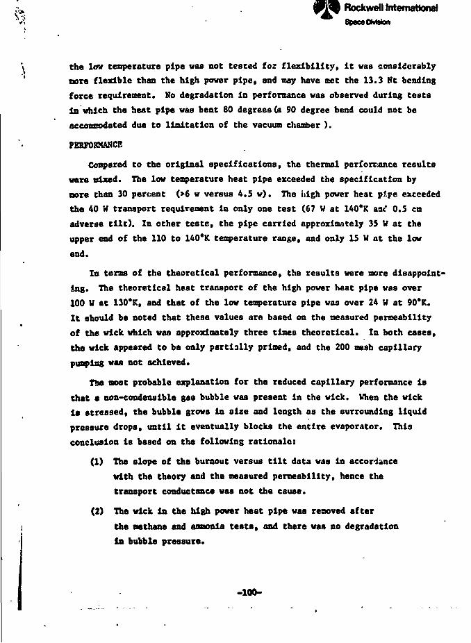
Rockwell InternationalSpace OMston
\ the low temperature pipe was not tested for flexibility, it was considerably' more flexible than the high power pipe, and may have met the 13.3 Nt bending
force requirement. Mo degradation in performance was observed during tests
in which the heat pipe was bent 80 degrees (a 90 degree bend could not be ;
accommodated due to limitation of the vacuum chamber ). I
PERFORMANCE 'I
Compared to the original specifications, the thermal performance results \
were mixed. The low temperature heat pipe exceeded the specification by
more than 30 percent (>6 w versus 4.5 w). The high power heat pipe exceeded !
the 40 W transport requirement in only one test (67 V at 140*K aal 0.5 cm
adverse tilt). In other teste, the pipe carried approximately 35 V at the
upper end of the 110 to 140*K temperature range, and only 15 W at the low
end.
In terms of the theoretical performance, the results were more disappoint- ',
ing. The theoretical heat transport of the high power heat pipe was over p
100 V at 130'R, and that of the low temperature pipe was over 24 W at 90'R. 1
It should be noted that theae values are based on the measured permeability f* *
of the wick which was approximately three times theoretical. In both cases, \
the wick appeared to be only partially primed, and the 200 mesh capillary
punping waa not achieved.
The moat probable explanation for the reduced capillary performance is j
that • non-condenslble gas bubble was present in the wick. When the wick Ii* stressed, the bubble grows in size and length aa the surrounding liquid ;
pressure drops, until it eventually blocks the entire evaporator. This '
conclusion is based on the following rationale: i
(1) The slope of the burnout versus tilt data was in accordance
with the theory and the measured permeability, hence the
transport conductance was not the cause.
(2) The wick in the high power heat pipe waa removed after
I the methane and amonia testa, and there was no degradation
in bubble pressure.
-100-
Rockwell InternationalSpmDfcMon
(3) Haas spectrometry tests on the methane Indicated relatively
high concentration levels of methane and other non-condensible
trace contaalnants (40 ppm of nitrogen in the heat pipe after
outgaasing). The impurites were due to trace contaminants
in the supply bottle and not due to corrosion as evidenced
by the fact that the impurity levels in the heat pipe were
generally lover than in the supply bottle, and hydrogen
levels were insignificant.
(4) Test data with both the high power and the low temperature
heat pipe indicate that the wick vaa pumping at levels
which exceeded the open composite pumping capability, sothe wick must have been primed at least to some degree.
The problem of composite and artery wicks in the presence of noc-
condenaible gas is not new. With cryogenic fluids, the problem is even
more acute because of the high solubility of non-condeaBible gases. In
addition, the solubility decreases with increasing temperature for most gases,
the dissolved gas in the condenser section would tend to come out of
solution at the slightly warmer evaporator.
RECOMMENDATIONS
It la strongly recommended that further research and testing be
conducted to determine the mechanisms of permature burnout in composite
wicks with cryogenic fluids, and to develop systems or processing procedures
to overcome this problem in fixed conductance heat pipea. Methods of
reducing the room temperature contaminant pressure should also be investigated.
These may Include solid or liquid absorbent materials, or techniques such
as on-orblt charging from a pressure bottle. Applications for flexible heat
pipe technology are many, and further research should be continued.
I,
-101-
RockweO International
REFERENCES
1. Wright, J. P. and W. R. Fence. Development of a Cryogenic Heat Pipe
Radiator for a Detector Cooling Syatcta. ASME Paper No. 73-ENAa-47,
July 1973.
2. Saaaki, E. and J. P. Wright. A Flexible Cryogenic Heat Pipe. AXAA
Paper No. 75-658, May 1975.
3. Technical Proposal for a Flexible Cryogenic Heat Pipe Development |
I Program. Rockwell Space Division, SD 74-SA-0188-1 (January 29. 1975).ti 4. Schlitt, R., et al. Paraaetrtc Performance of Extruded Axial Grooved
| Heat Pipes froa 100 to jQO'K. AIAA Paper No. 74-724, July 1974. '
5. Harwell, W., et al. Cryogenic Heat Pipe Experiment. AIAA Paper
Ho. 75-729, May 1975.
6. Quadrini, J. and R. Kosson. Design. Fabrication, arid Testing of a
Cryogenic Thermal Diode. Interim Report, NASA CR-137616, Deceaber 1974.
7. Kirkpatriek, J. P. and P. J. Breniian. Performance Analysis of the
Advanced Thermal Control Flight Experiment* AIAA Paper No. 75-727,
May 1975.
8. Marcus, B. D. Theory and Design of Variable Conductance Heat Pipes.
NASA CR-2018, April 1, 1972.
9. Wright, J. P. et al. Development and Test of Two Flexible Cryogenic
Heat Pipes. AIAA Paper No. 76-478, July 1976.
10. Heat Pipe Technology - Final IR&D Report for CFY 1975. Rockwell Space
Division, SD 75-SA-0200, December 1975.
11. Saaaki, E. W. Heat Pipe Temperature Control Utilizing a Soluble Caa
Absorption Reservoir. NASA CR-137792, February 1976.
PACK BLANK FOR TSJU9-103-
Rockwrilfntemrttond
1
I <
APPENDIX A
UICKPER PROGRAM UTILIZATION MANUAL
SD 77-AP-0088
Rochwofl (ntomottonol
CONTENTS
• Section
i.o;- 2.0'V
; 2.22.3
I 2.3.1
• 2.3.2
* 2 3 3, £.•>.<!
5? 9 AI- 2.4t»
2.5£! 3'°; 3.1>j 3.2
1 3'3
! 3.3.1
! 3"3*2
'. „, 'i. — - .-. <~ • -* - -»
V
INTRODUaiON
ANALYSIS
Mick System Configuration
Kick Properties
Heat Transport Capability of Mick
Main Wick
Heat Transport Capablllv of Heat
PROGRAM DESCRIPTION
Output Description .
W1ck Optimization
Performance of Optimized Wick
NOMENCLATURE
FLOWCHARTS
Page
.... A-1
.... A-1
.... A-1
.... A-2
Elements A-3
A-5
. . . . A-6
?1pe . . A-8
A-14
a.ic
A-19
St> 77-AP-0088
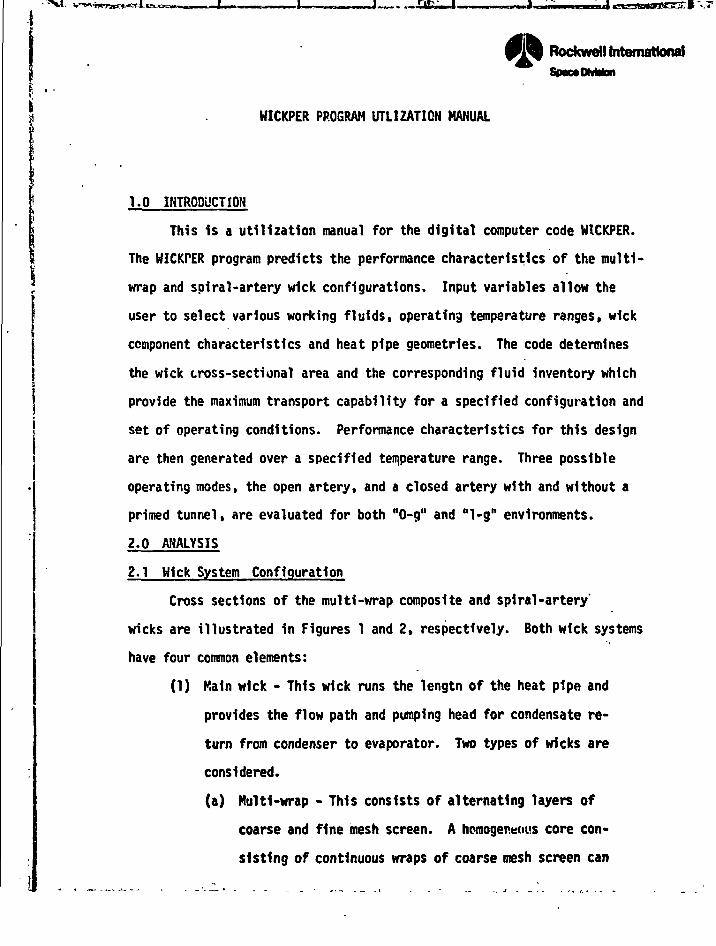
__,.-£fc— ..
~ .... - ~~n. —- ••-. — t- -^: •••*-,& |1 • ....IcaaBMaBBSgirlvr J
Rockwell InternationalSpaMttvWan
HICKPER PROGRAM UTLIZATIQN MANUAL
•;il
1.0 INTRODUCTION
This is a utilization manual for the digital computer code WICKPER.
The HICKPER program predicts the performance characteristics of the multi-
wrap and spiral-artery wick configurations. Input variables allow the
user to select various working fluids, operating temperature ranges, wick
component characteristics and heat pipe geometries. The code determines ?I
the wick cross-sectional area and the corresponding fluid inventory which •
provide the maximum transport capability for a specified configuration and •d
set of operating conditions. Performance characteristics for this design *3
are then generated over a specified temperature range. Three possible 1
operating modes, the open artery, and a closed artery with and without a
primed tunnel, are evaluated for both "0-g" and "1-g" environments.
2.0 ANALYSIS
2.1 Hick System Configuration
Cross sections of the multi-wrap composite and spiral-artery'
wicks are illustrated in Figures 1 and 2, respectively. Both wick systems jj
have four common elements:
(1) Main wick - This wick runs the lengtn of the heat pipe and \
provides the flow path and pumping head for condensate re-
turn from condenser to evaporator. Two types of wicks are
considered.
(a) Multi-wrap - This consists of alternating layers of
coarse and fine mesh screen. A homogeneous core con-
sisting of continuous wraps of coarse mesh screen can
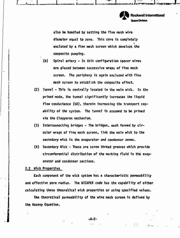
I
Rockwell InternationalStMceDMstan
also be handled by setting the fine mesh wire
diameter equal to zero. This core 1s completelyi
enclosed by a fine mesh screen which develops the
composite pumping.
(b) Spiral artery - In this configuration spacer wires
are placed between successive wraps of fine mesh
screen. The periphery is again enclosed with fine
mesh screen to establish the composite effect.
(2) Tunnel - This is centrally located in the main wick. In the
primed mode, the tunnel significantly increases the liquid
flow conductance (KA), therein increasing the transport cap-
ability of the system. The tunnel is assumed to be primed
via the Clapyeron mechanism.
(3) Interconnecting bridges - The bridges, each formed by cir-
cular wraps of fine mesh screen, link the main wick to the
secondary wick in the evaporator and condenser zones.
(4) Secondary Wick - These are screw thread grooves which provide
circumferential distribution of the working fluid in the evap-
orator and condenser sections.
2.2 Hick Properties
Each component of the wick system has a characteristic permeability
and effective pore radius. The WICKPER code has the capability of either
calculating these theoretical wick properties or using specified values.
The theoretical permeability of the wire mesh screen 1s defined by
the Kozeny Equation.
-A-2-
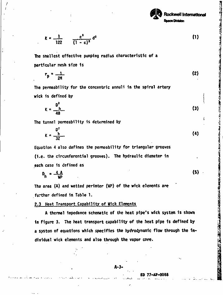
ITtefnstionol
StxxaDMaton '1
122(1)
(1 -
The smallest effective pumping radius characteristic of a
particular mesh size 1s
'''•«-The permeability for the concentric annul i In the spiral artery
wick 1s defined by
D2K = _h_
48
The tunnel permeability is determined by
Equation 4 also defines the permeability for triangular grooves
(I.e. the circumferential grooves). The hydraulic diameter In
each case is defined as
(2)
(3)
(4)
(5)h HP
The area (A) and wetted perimter (WP) of the wick elements are
further defined in Table 1.
2.3 Heat Transport Capability of Wick Elements
A thermal Impedance schematic of the heat pipe's wick system Is shown
in Figure 3. The heat transport capability of the heat pipe Is defined by
a system of equations which specifies the hydrodynamic flow through the In-
dividual wick elements and also through the vapor core.
!i\
4
^
I
\
I
'A
A-3-
SD 77-AP-0088
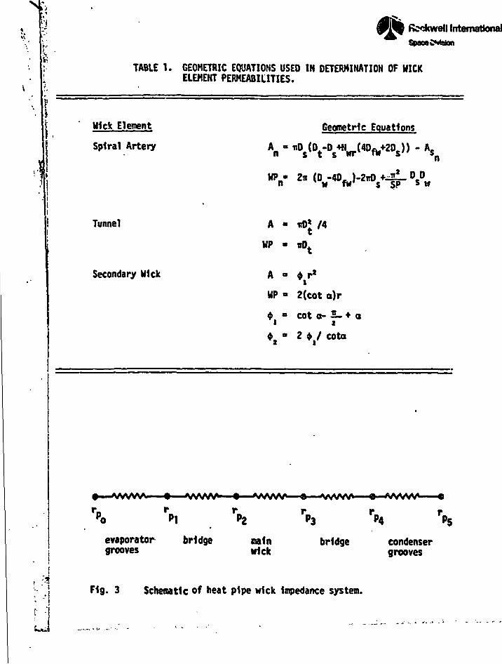
1 •<»«H
/
ajir-^wi
InternationalSpsffoCMglon
TABLE 1. GEOMETRIC EQUATIONS USED IN DETERMINATION OF HICKELEMENT PERMEABILITIES.
Hick Element
Spiral Artery
Geometric Equations
HP •n
Tunnel A • nOj /4
WP « irth
Secondary Wick A
UP
*a
*
2(cot o)r
cot o- 2_ + ai
2 <fr / cota
•—•w/vw. • *wwv» • wvw* • vww 9
P2
evaporator bridge maingrooves wick
bridge condensergrooves
!-1
r- ,
F1g. 3 Schematic of heat pipe wick Impedance system.
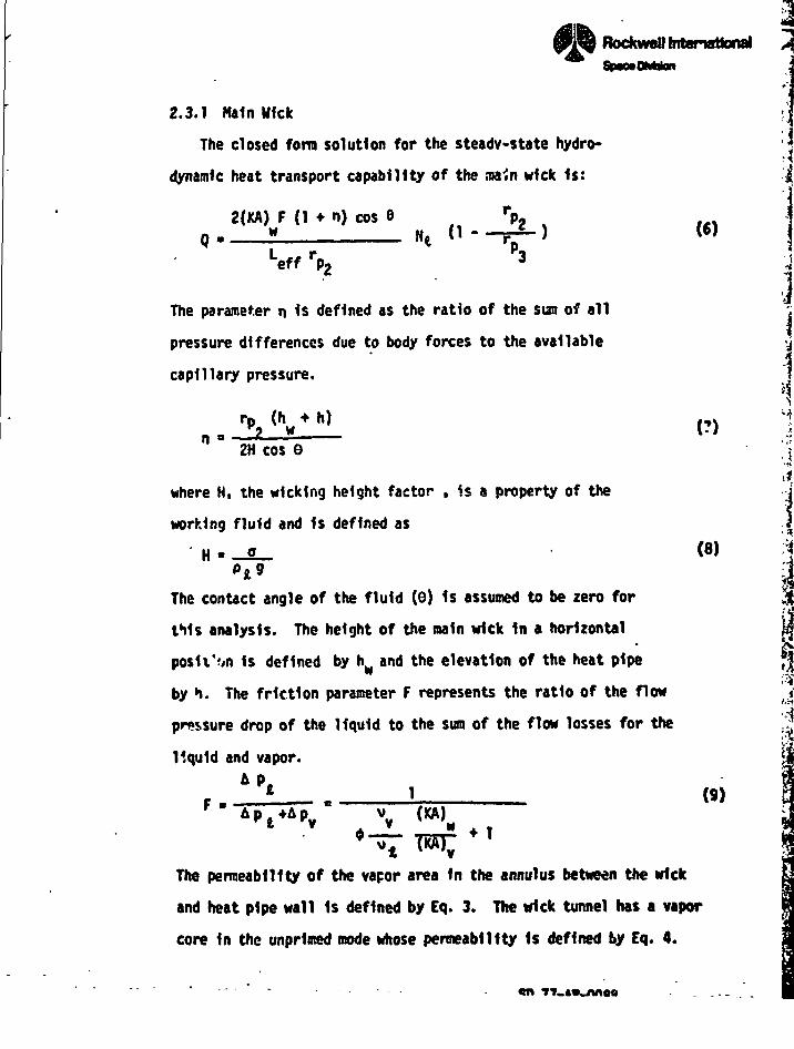
" I '' J"—
«*=•
/.'• ; /
, L_J - — .«»_— J — _-~—. ~=^>-
I' 'V»Jk_
^ .^•.•j—
BockwcOlnteriaMonal >
2.3.1 Main Wick
The closed form solution for the steady-state hydro*
dynamic heat transport capability of the ,ua.n wick 1s:
2(KA) F (1 * n) cos 6Q 2 HI 0-
r>2 )Leff rP2
The parameter n 1s defined as the ratio of the sun of all
pressure differences due to body forces to the available
capillary pressure.
2H cos 6
where H, the wlcklng height factor , is a property of the
working fluid and 1s defined as
H • qotg
The contact angle of the fluid (0) 1s assumed to be zero for
this analysis. The height of the main wick In a horizontal
posit'on Is defined by h^ and the elevation of the heat pipe
by h. The friction parameter F represents the ratio of the How
pressure drop of the liquid to the sum of the flow losses for the
liquid and vapor.4P<
F • TT"
<«
(9)
The permeability of the vapor area In the annulus between the wick
and heat pipe wall Is defined by Eq. 3. The trick tunnel has a vapor
core In the unprlmed mode whose permeability Is defined by Eq. 4.
'•<!
,
'•*
fj
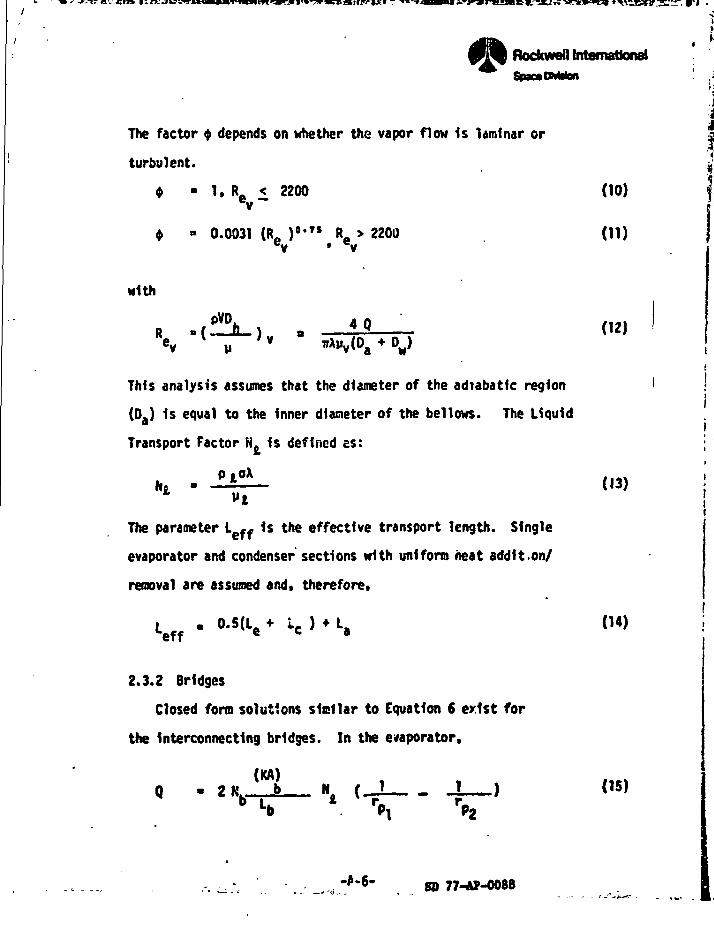
/•' ' •. I -
,i™[iix_i»ciDziiix3 i;pRochweQ tntemsttona)
The factor $ depends on whether the vapor flow Is laminar or
turbulent.
4 • 1, Re < 2200 (10)
* - 0.0031 (Ra )°>TS Ra > 2200 (11)
ev • v
with
This analysis assumes that the diameter of the adiabatlc region ' !
(Da) 1s equal to the Inner diameter of the bellows. The Liquid
Transport Factor N. Is defined es: ; -'(
(13) !
The parameter Leff 1s the effective transport length. Single
evaporator and condenser sections with uniform heat addlt.on/
removal are assumed and, therefore.
Leff - 0-5Ue * lc ) * La (14)
2.3.2 Bridges
Closed form solutions similar to Equation 6 exist for
the Interconnecting bridges. In the evaporator,
(KA)Q - 2Kh_fe_ \ (_J ! ) 05)
D i. * r« r_
8D 77-AP-0088
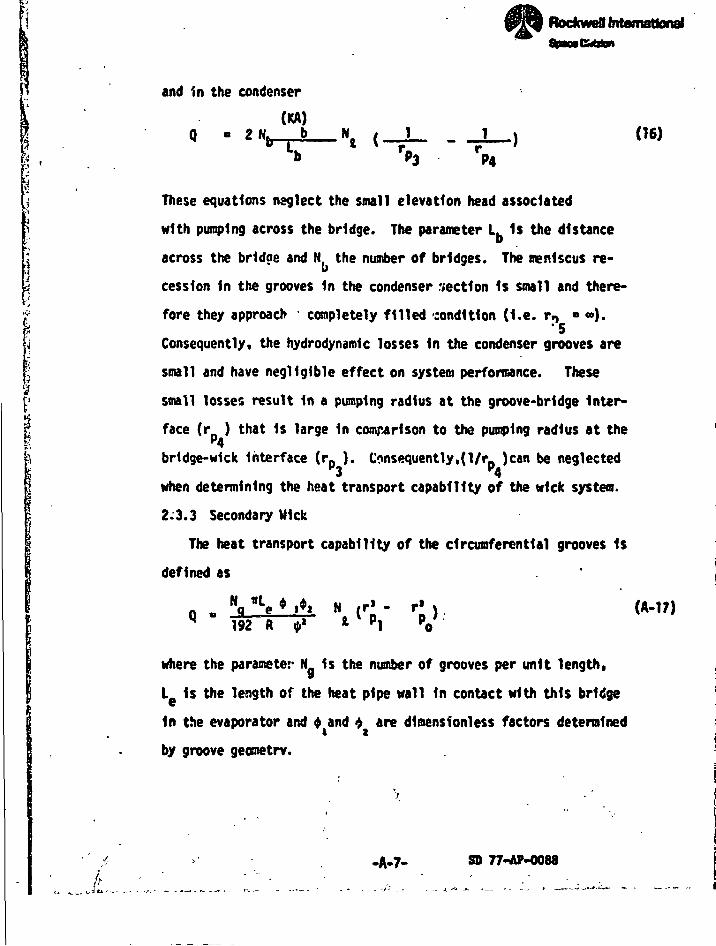
4"i
t<t
»,t
\i
Rockwefl Internationali
tand in the condenser
(KA)
--^- -J- --1— 06)*•* r« rb P3 P4
These equations neglect the small elevation head associated
with pumping across the bridge. The parameter L Is the distance
across the bridge and N the number of bridges. The meniscus re-
cession in the grooves 1n the condenser r«ect1on Is small and there-
fore they approach completely filled condition (I.e. rp « «).
Consequently, the hydrodynamic losses in the condenser grooves are
small and have negligible effect on system performance. These
small losses result 1n a pumping radius at the groove-bridge Inter-
face (r ) that is large In comparison to the pumping radius at the"4
bridge-wick interface (rp }. Consequently,(l/rp )can be neglected
I when determining the heat transport capability of the wick system.
2.3.3 Secondary Mick
The heat transport capability of the circumferential grooves 1s
defined as
92 R «• l
where the parameter N is the number of grooves per unit length,
L Is the length of the heat pipe wall in contact with this bridge
in the evaporator a
by groove geometry.
in the evaporator and 4 and •> are dioensionless factors determined
SD 77-AP-0088
"• "-^-•-.-..„ '\ I /
RoclcweU International
The parameter R Is the Inner radius of the heat pipe and $
Is the distribution angle or half the angle between a bridge
pair. A uniform distribution of bridges Is assumed and hydro-
static losses associated with pumping the liquid around the
grooves are neglected. It is further assured that the grooves
are sharp and therefore the pumping radius of the evaporator
grooves at the maximum distance from the bridges (r } approaches
zero at maximum stress.
2.4 Heat Transport Capability of the Heat Pipe
The heat transport capability of the heat pipe is defined by the simul-
taneous solution of the system of individual transport equations. As illustrat-
ed In the wick system sch&natlc In Fig. 3, the pumping radii of the various
wick elements are equal at common interfaces. Additionally, these radii adjust
to provide uniform heat transport across each element within the system.
The maximum transport capability of a heat pipe will be United generally
by either the main wick or the grooves. If the maximum heat transport of the
wick system requires a pumping radius at the groove-bridge Interface (rp ) which
is greater than the pore radius of the fine nesh screen used for the bridges and
the main wick envelope, the grooves are limiting. IF the grooves are capable
of providing the maxlBum heat pipe transport with a value of(r 1 which Is less
than the fine mesh pore radius, the main wick 1s limiting.
The system of individual transport equations 1s highly non-linear In a
•1-g" environment. The UICKPCR code uses an incremental type e*ocedure to con-
verge on the systea solution. For the "o-g" environment, the transport equation
for the main wick (Eq. 6) Is simplified and explicit solutions for the effect-
Ive pumping radii and corresponding heat transport are used.
-A-ft-
x-\'-'—\— 1
"~~-r ' | . •"*
RocfcweBlntanttttonal „
2.S Fluid Inventory
Ihe m»ss of the working fluid required for heat pipe operation Is
determined for the optima wick design. The m&ss of fluid required to
satisfy each Individual wick element Is calculated and then suaned to
determine the total inventory. For the main wick and interconnecting
bridges* the liquid masses are defined by
and
For the main wick tunnel in the primed mode
The mass of liquid required for the circumferential grooves is
Pt(WC) (1. * Lc)
The mass of vapor contained in the annul us between the oain wick
and the heat pipe envelope is
m P¥( (AL)C
The mass of vapor present in the wick tunnel in the unpriced
node is
S ' »»(AL'tThe sum of the liquid and vapor mass charges for the individual
elements yields the total fluid requirement.
(18)
(19)
(20)
(21)
(22)
(23)
•A-9- SO 77-AP-0088
J**Rcckwoflfntemsttonri
1
For the unpriced tunnel node:7
m * " f l » * o « *o. * O * B (24) -f w 4b £g ^ vt j
and for the primed tunnel naode * :'i
Bf • tf. * O. * O. + D. * O »f *« S 49 4t v (25)
3.0 PROGRAM DESCRIPTION
3.1 General
The UICKPCR program and the supplemental subroutines were written
In FORTRAN EXTENDED and designed to operate on the COC 6600 system.
The program listing and flow charts are contained In Appendix A. All
of the constants and variables utilized within the program are identif-
ied at the beginning of the program listing. The program deck consists
of job control cards, a progran source deck, input data cards and pro-
gram termination cards. The heat pipe geometries,wick properties,
fluid properties and program options are defined by the Input data.
UICKPER is structured In two stages. The prograa Initially deter-
mines the wick cross-sectional area which provides optimum performance '
for the closed artery/unpriced tunne' operating code In a '1-g" environ-
ment. The performance characteristics of this wick configuration are
then generated either for a "o-g" or "1-g" environment in three oper-
ating modes:
(1) Open Artery - The sain wick's pumping head Is limited to the
oaiiBua head developed by the coarse aesh or spiral annul us.
(2) Closed ArtertfUnprimed Tunnel - The caln wick's capability
Is Halted by the aaxioum puaping head developed by the fine
•esh screen envelope. --
-A-10-fe!
» • k -*•»
• I ?** prre:hreM***o At«jB"Him»
(3) Closed Artery/Prim** Tunnel - The pumping head developed
by the fine oesh screen 1s Hailing and the flow conduct*
ance of the tunnel (KA), is added to the liquid's How con-I l
I ductance In the main wick.
Several subroutines supplement HICKPCR. Their names and functionsi
are listed below:
• FLUPRT - Inputs and outputs fluid properties.
• KULWRAP - Calculates wick and vapor core geometry and flow con-
ductarrc for the multi-wrap wick configuration.
• SPIRART - Calculates wick and vapor core geometry and flow conduct-
ance for the spiral artery wick configuration.
O BRIDGE - Calculates and outputs geometry and flow conductance of
Interconnecting bridges.
| • HFKWP - Calculates and outputs the fluid mass charge for the
j multi-wrap wick configuration.
| Saoole Inputs and outputs are presented 1n the following section andi| In Appendix A to Illustrate UICKPCR program operation.
| 3.2 Input Description
A listing of the Input deck 1s shown 1n Table 2. The FOftTfUM var-
iables and constants are Identified at the start of the progran listing
In Appendix A. The Input cards allow the user to select heat pipe geom-
etries, wick element characteristics, fluids* operating teapeiature*.
environments ("o-g" or "1-g") and overall wick configuration (multi-wrap
or spiral artery).
A sample Input sequence is presented fn Table ). The program options,
specified by the Input on card no. 3. are detailed below:
--- 80 77-A*-008d
• 1
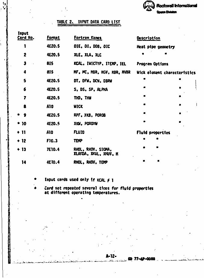
InputCard No.
1
i 2
3
i 'j s1 £
i *
|
1 '
8
* 9
* 10
* 11
• 12
* 13
14
•
•
i
TABLE
^^ RodtwaSbitem^onal
2. INPUT OATA CARD LIST
Fortaat Fortran Hames Description
4E20.5 DIE, 01. DOS. DIG Heat pipe geonetry
4E20.S XLE. XLA. XLC *
815 KCAL, IUICTYP, ITEKP. I EL Prograa Options
815 KF, PC. HER, NOV. BBft. IWBR Hick elecent characteristics
4E20.5 OT. OFW, DCH. DBRJ " " |
4E20.5 S. OS. SP. ALPHA " * •
4E20.5 THD. Tl« " "
AlO WICK " '
4E2C.5 RPF. XKB. POR08 " "
4E20.5 Xm. POft&U " "
AlO FLUID Fluid properties
F1C.3 TE«P " "
7E10.4 RKOL. RHOV. SIGMA. " "XLAKOA, XKUL, XMUV. H
4E10.4 RKOL. RKOV. TEKP * '
Input cards used only \f KCAL ^ 1
Card set repeated several tines for fluid propertiesat different operating temperatures.
•
• '
JU12»- . - <i, • -_ ^^^^ .Z-zZ.' *** ** 77- -0088 ,. , ^ __*o^*-
•
)
t
\
}}«
' j
1t
I
\/
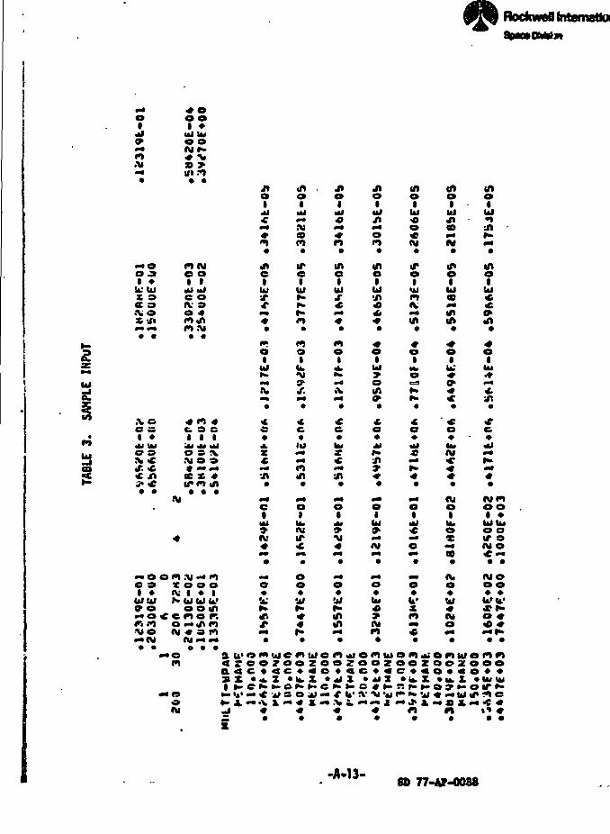
I I I I I" I '* r - fc- -I— -~,U, ., w l~ . I ," f^|--c^^Ul*er«l&
Bockwefl International
£
oI
0 o1 »
UJ (M00
« •>»3D >«n ?o
I
C
ilM
M
1u</I
(ftoI
UI«o«M
iklrf»CD
M
(ftI
MOO JI »
u; uiX 9cc oSi/IM M
«Me oi ic oIV 9O «
tbJ
IUI
inoi
UIf
iniuiin•a
n:
»roInIV
in
iuiCO
inm
inoUJ
o-•n
iUI
UI
s!
oIu.
•V9f.
oI
o>n
xoe I *O 9
>. «
c. 9 eI i ii« •*• UJO 9 X.X O 9
CC * *
X M
- S -X
in•s\
Mi
MtI
U.
IT
O
u>(W
nio
i.
» »M M
4 M *CO
MmooI »UJUto e
M MO
e 9i «UIUI90
onx
: eo(M
M M »^O O OI • IUlblk.'o o innor.M «n m•• 9 wMMMo
ei•n
oo
M M M ft.
inin
Ui« b*
nM M
tat
MO
MOO O
U-'U.1
M
au 'om>j iemuiom«4iomuion^>omuofo i ' i470O700ZOOZOOZOOZOOZOOOa«c«<c««o*«c««e*«o*«o«*S X • «. Z • U. X *«IX • ** Z «u.X •*», X *b<lMI »-e*k^o»>^>e*»i-e«^>Rfk»-c>9»-oir^-*• u»». c •*> s o j •• * u* JV' >» •*< r* •* *wj « •« u» tf» •?•> e*-X**<V&M4 £M.>.&.MMjMj»&.«a*.M<C«j « « « « n n %»*
SD 77-Af-0088
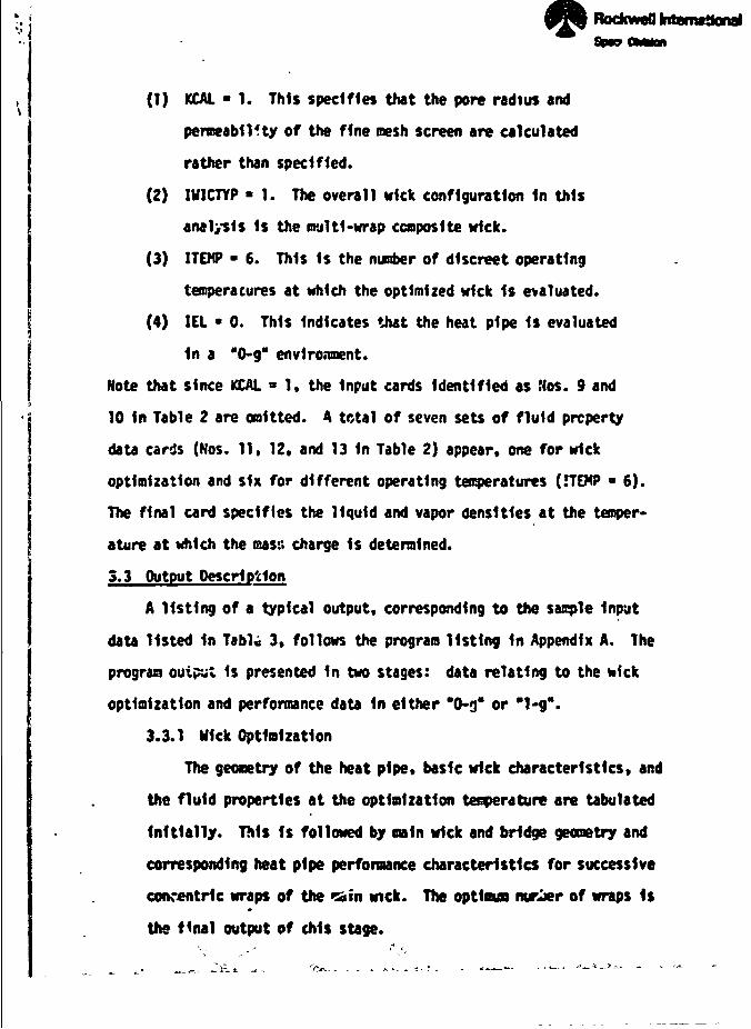
i • r I I !_ r; 7:1:21*- I
(1) KCAL • 1. This specifies that the pore radius and
permeability of the fine mesh screen are calculated ;
rather than specified. ;
(2) IU1CTYP • 1. The overall wick configuration In thisp
analysis 1s the multi-wrap composite wick. j
(3) ITEHP • 6. This Is the number of discreet operating . *
temperacures at which the optimized wick Is evaluated. •
(4) IEL • 0. This Indicates that the heat pipe Is evaluated j
1n a "0-g" environment. *
Note that since KCAL « 1, the Input cards Identified as Nos. 9 and
10 In Table 2 are omitted. A total of seven sets of fluid property
data cards (Nos. 11, 12. and 13 In Table 2) appear, one for wick
optimization and six for different operating temperatures (HEMP » 6).
The final card specifies the liquid and vapor densities at the temper- "
atore at which the masn charge Is determined.
3.3 Output Description *
A listing of a typical output, corresponding to the sample Input *
data listed In Tab1« 3, follows the program listing In Appendix A. The :
program output is presented In two stages: data relating to the wick 1
optimization and performance data In either "0-g" or "1-g". j
3.3.1 Hick Optimization |
The geometry of the heat pipe, basic wick characteristics, and 1
the fluid properties at the optimization temperature are tabulated *
Initially. This Is followed by main wick and bridge geometry and j
corresponding heat pipe performance characteristics for successive
concentric wraps of the *sain wick. The optlaus rarier of wraps Is
the final output of this stage.
• Vlr tT TfftS»i Tl'r£ TB« -trt?*.»i'TrMJ ^ «
-A-15-•SD 77-4F-0088
Rockwell InternationalSpace OMrion
3.3.2 Performance of Optimized Hick
The fluid properties at the operating temperature are listed
first, followed by the heat pipe performance characteristics for
the three possible operating modes: open artery and closed artery,
with and without a primed tunnel. This includes heat transport
capability, flow pressure drop ratio, Reynold's number of the vapor ?
flow and the effective pumping radii at the wick element interfaces. \
If the heat pipe 1s evaluated in an "1-g" environment, the heat pipe !
performance characteristics are output at several heat pipe elevations
ranging from a horizontal orientation to the static wlcking height. i
This entire output is repeated for each operating temperature. [
P
1-
Symbol
A
C
D
°hd
F
H
"w
h
K
L
.H
m
N
N£
P
Q
R
r
Re -. - v
rp
SP
NOMENCLATURE
Description
area
circumference
diameter
hydraulic diameter
wire diameter
pressure drop ratio
wlcklng height factor
wick height
elevation of heat pipe
permeability
length
mesh size
mass
number of ...
liquid transport factor
pressure
axial heat flow rate
heat pipe Inner radius
groove meniscus radius
Reynolds number
pumping radius
distance between spacer wires
jRfeRocfcSpace
Unit
m*
m
m
m
m
m*
m
m
m*
m
nf1
3
.
W/m*
N/m*
W
m
m
m
m
V «
I International
ii
!'S
ft
-A-16- 77-AP-0088
»_ • * ft*' I ' 1 1 - - - - - - - -—• ~ i ~ - , _ ^-. , f M^na «v -«.-, -—» § »•, -T
fc^-tUnim.* JUnL--3j_ I. -• I -I I IV- '• r»-* T i '" —-^-—• MII. H^P^ ..-. .— |* —mrn—nar"vr| L—n m^m li - - - _ . . _i r,_ li—rn m«-M.i "r"1"
Symbol
V
WP
a
8
c
n
e
X
V
V
p
0
«*Subscript
a
b
c
e
eff
fw
9
i
NOMENCLATURE (Continued)
Description
velocity
wetted peremeter
groove half angle
heat pipe orientation withrespact to gravity
porosity
gravity factor
contact angle (fluid and wick)
heat of vaporization
dynamic viscosity
kinematic viscosity
density
surface tension
groove geometry factor
fluid distribution angle
adlabatlc
bridge
condenser
evaporator
effective
fine wire
groove
liquid
PlrTocimspmn
Unit
m/s
n
rad
rad
rad
0/kg
N-s/m1
n»/s
kg/ni1
N/m
rad
£
%krl
,K
I
*jS
-A-17- SO 77-*P-0°*8
Jiv ,*/
RockweB International
NOMENCLATURE (Continued)
Subscript Description
n nth wrap of wick
s spacer wire
t tunnel
v vapor ;
i
w wick
wr wraps
-A-18-
SD 77-AP-0088
rfw -«
RockwsB tntcmattonal
UICKPER FLOWCHARTS
f
•,,4
8
i<
>
8D 77-AP-0088
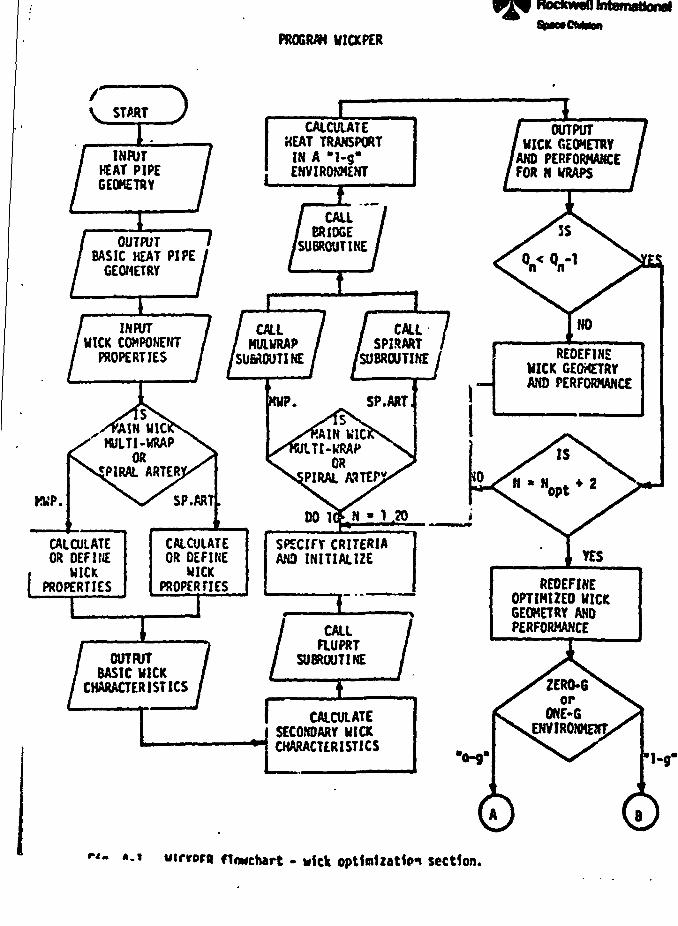
^f ~—l-r- , [ - . . . ! I I
PROCWH WIOCPER
Rodcwefl International
/V S T A R T
INPUTHEAT PIPEGEOMETRY
CALCULATEHEAT TRANSPORT
IN A "1-g"EHVIROKMENT
OUTPUTWICK GEOMETRYAND PERFORMANCEFOR N WRAPS
OUTPUTBASIC HEAT
GEOMETRYPIPE
CALLBRIDGE
I SUBROUTINE7I
INPUTWICK COMPONENT
PROPERTIES
CALLNULURAP
SUBROUTINE
CALLSPIRART
SUBROUTINE / REDEFINEWICK GEOMETRYAND PERFORMANCE
MULTI-WRAPOR
SPIRAL ARTER
CALCULATEOR DEFINE
WICKPROPERTIES
CALCULATEOR DEFINE
WICKPROPERTIES
SPECIFY CRITERIAAND INITIALIZE YES
OUTPUTBASIC WICK
CHARACTERISTICS
CALLFLUPRT
SUBROUTINE iREDEFINE
OPTIMIZED MICKGEOMETRY ANDPERFORMANCE
1
CALCULATESECONDARY WICKCHARACTERISTICS
ZERO-Gor
ONE-GENVIRONMENT
•"«- finnchart - wick optimization section.
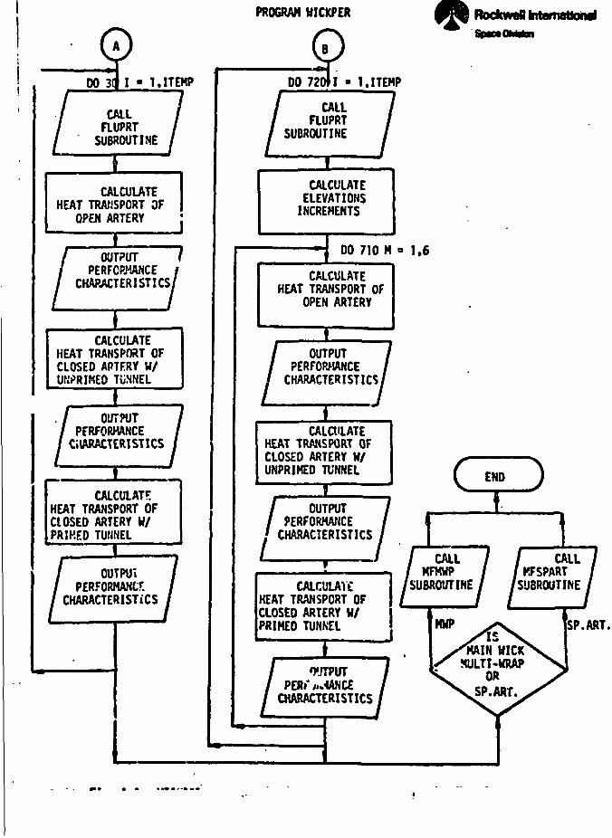
•:«4 I i__J .J.I tr*w.'taml.rji*itMi«mi> faims-naaaxk
.ITEMP
CALLaUPRT
SUBROUTINE
CALCULATEHEAT TRANSPORT OF
OPEN ARTERY
CALCULATEHEAT TRANSPORT OFCLOSED APTFRY H/UWRIMED TIJNNEL
OUTPUTPERFORMANCE
CHARACTERISTICS
CALCULAT?-HEAT TRANSPORT OFCLOSED ARTERY W/PRIMED TUNNEL
OUTPUTPERFORMANCE
CHARACTERISTICS
I
OUTPUT fPERFORMANCE /
CHARACTERISTICS/
PROGRAM HICKPER RocfcweB international
DO 720*1 » KITEHP
CALLFLUPRT
SUBROUTINE
JLCALCULATEELEVATIONSINCREMENTS
00 710 N a 1,6
CALCULATEHEAT TRANSPORT OF
OPEN ARTERY
OUTPUTPERFORMANCE
CHARACTERISTICS]
ICALaiLATE
HEAT TRANSPORT OFCLOSED ARTERY H/UNPRIMED TUNNEL
' OUTPUT?ERFORHAT;CE
CHARACTERISTICS
CALCULAYCHEAT TRANSPORT OFCLOSED ARTERY W/PRIMED TUNNEL
OUTPUT».<(ANCE
CHARACTERISTICS
CALLMFKWP
SUBROUTINE
CALLKFSPARTSUBROUTINE
SP.ART.
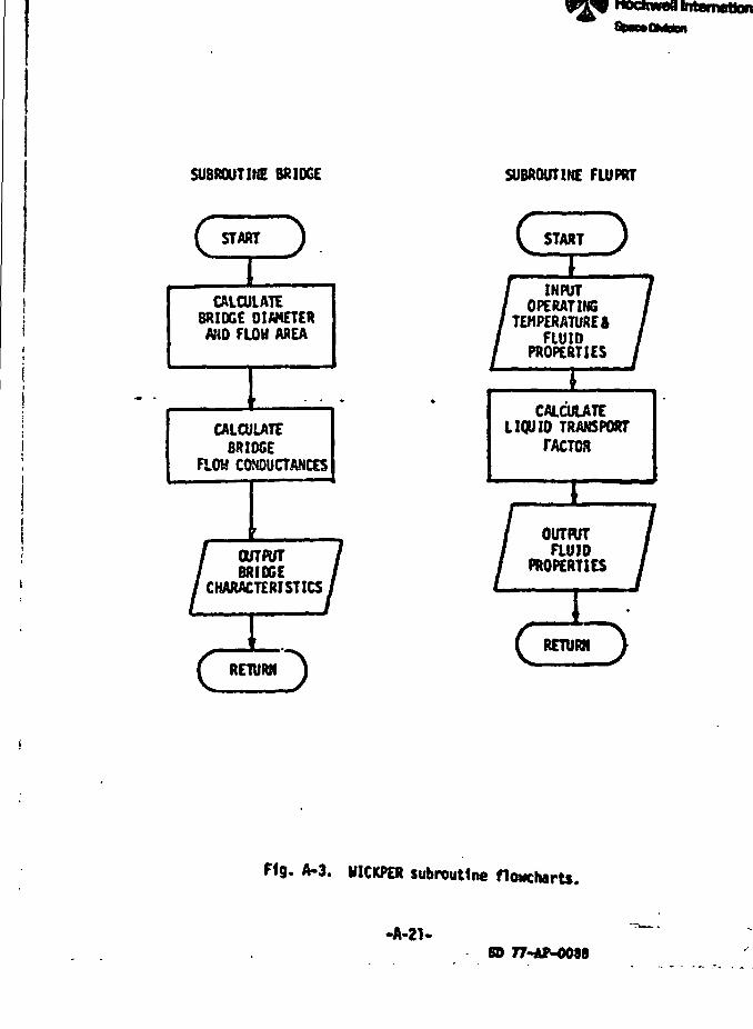
fit. ea»£ §?•>:» -«
dnwBtnt
SUBROUTINE BRIDGE SUBROUTINE FLUPRT
C START J
CALCULATEBRIDGE DIAMETERAND FLOW AREA
CALCULATEBRIDGE
FLOH CONOUQANCES
OUTPUTBRIDGE
CHARACTERISTICS
IRETURN3
START )
INPUTOPERATING
TEMPERATURESFLUID
PROPERTIES
CALCULATELIQUID TRANSPORT
FACTOR
OUTPUTauio
PROPERTIES 7RETURN
F<g. A-3. WICKPER subroutine flowcharts.
-A-21-8D 77-AP-0088
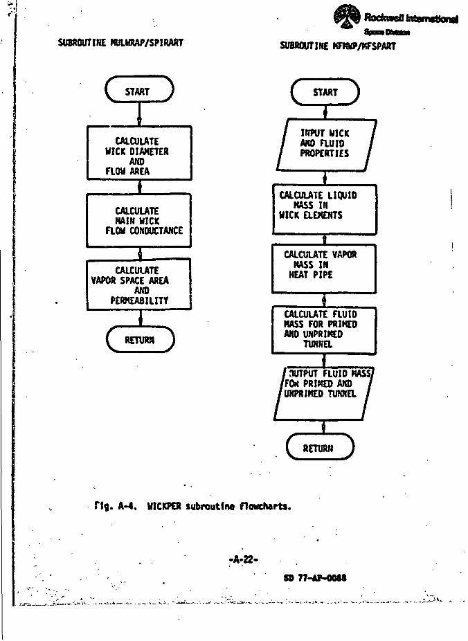
SUBROUTIHE KULURAP/SPIRART SUBROUTINE
START J
CALCULATEUICK DIAKETER
ANDAREA
CALCULATEMAIN UICK
FLOW CONDUCTANCE
CALCULATEVAPOR SPACE AREA
ANDPERMEABILITY
(RETURM
C START
INPUT WICKAMD auioPROPERTIES
CALCULATE LIQUIDMASS IN
UICK aEMENTS
J_
CALCULATE VAPORMASS INNEAT PIPE
CALCULATE FLUIDMASS FOR PRIKEOAND UNPRIME0
1nUTPUT FLUID MASS/(FOX PRIMED AMD'UNPRIMED TUNNEL
RETUffl J i\
F{g. A-4. UICKPER subroutine f1o»ch«rts.
•A-22-
5D 77-AP-004*
TS:
I "w™ .*"~v *~ f I T*1^-- ^ I. *
^_ 1
•
I\
*
OUTPUT
MICK OPTIMIZATION
-
Rodnscatntemgaonei
APPENDIX B
PARAMETRIC PERFORMANCE PREDICTIONS
(Theoretical Hick Properties)
. _ _.% __,I
200;
160
i§120
»- 60<KA).
vlck • • 0.9S3»oB(3/<Mn) bellow*
• 0.816 i 10*" «%'theortunnel dltaeter • 0.241*ca
ig 40 '
100 110 120 13fl 140 ISO |
TDIPCWmjRE. •! i '"— — — prfaed tunnel
• unprioed tunnel
1.0
»(
c •*i1
i *4s8
1 •'
>— >,
"*^— t
^^^"^-^
x
^^^
^^r *^
•_t .^-^ ;.
— *^
100 110 120 130 140 1!
1.0
•A
.* *>0
•• i8• t
*2
n» • -. .
TOVCWTUR|,H
. Hg. B-1. Perfomtnce characterlstlct^fMoh power . ^
,•
i]i
'I»
j
£»
240
200
80
40
0
\
/ Multi-wrap wick - - 1.27-cn (1/2-ln) bellowstunnel dtcaeler * 0.241-oa
(KA)._ • 0.740 a 10*n «*tneor
100 110 120 130
TCXPtRATURf. 'K
. ^._ priced tunnelunpriced tumwl
140 ISO
\i]
]it
6EE
•(
.4
100 110 120 130 140
TCXPCMraC. *K
i.o
.2
ISO
f 16. B-2.Performance cttar*cter(st1ca of Meh oooer flexibleheat pipe In 'o-g' (oethane)
I%
SD n-tf-ooaa
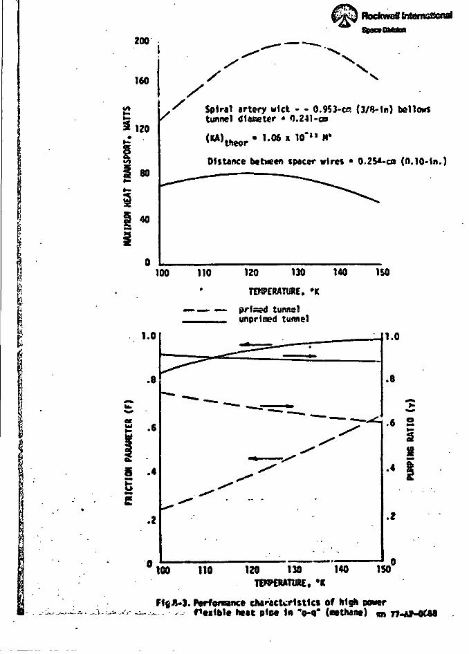
"*,
&r£pROCfcVlrCT jfiMf flMTOrU •=J
• 1
200 ^^ -^._ •
160
>-
3 120
' .|
1 80
ii 1 *1 -
/ X\ <
/ " - • 1x^ Spiral artery wick - - 0.953-ce (3/B-ln) bellows \
S tunnel diameter • 0.241 -co f)
(KA) • 1.M « 10*" N" j
Distance between spacer wires • 0.2SA-C0 (0.10-in.) "^
^^ -^^^^ - ;. I
^^^" 1
j
^
| 100 110 120 130 140 ISO J
1 . • TEKPERATURE. •* I& ' 4* — — — prised tunnel JS ufinrim>d tunnel 3
? ..1.0li
ii **\ **I 1/ S .4
5" . S
.2
— ^ ^^T
^"**" — •- **» ,_~~'~~~——-r^
^**^
^^ -*•"" - •
.-• -
^ '-
1.0 j
\
•8 1
-j ;
•• i ; \3 ' «!• 4 s
1 - - '• |i.
•* \\
i1
1!i °100 110 120 130 140 150" |
TCn^CMTlAC. °K |
" " • ' ; ' - • - f
- • -.- f*ei1ble heat plM In "o-q" («e thane) m 77<-tf-Ot88 i
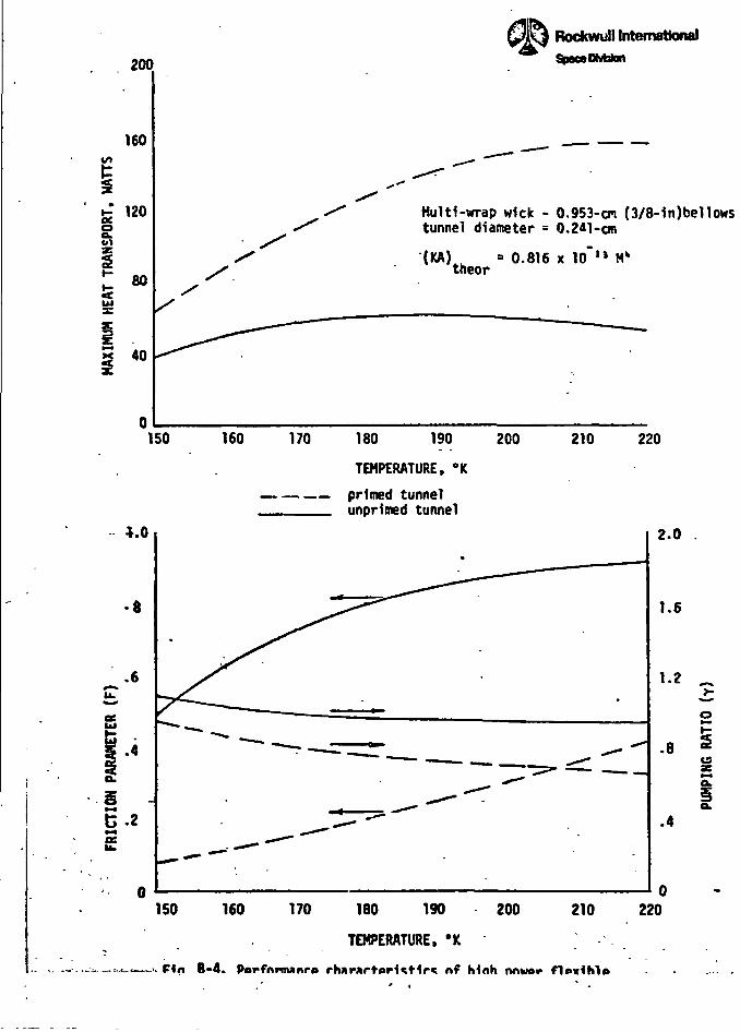
s&-
200
160
120
40
ISO
G.2£
Rockwull InternationalStoaMOMaton
Hultl-vnrap wick - 0.953-cm (3/8-in)bellowstunnel diameter = 0.2*1-on
(KA) • 0.816 x 10~IJ M*theor
160 170 180 190
TEMPERATURE, °K
primed tunnelunprimed tunnel
200 210 220
2.0
1.6
• *
ISO 160 170 180 190 200 210
TEMPERATURE, *K
-•. F<n B-4. PorfnrnwnrA rh»r«rt»r1«t1r« nf Mnh nnwer f1p*ih1»
220
^I
i ••'i
I ' 1
U
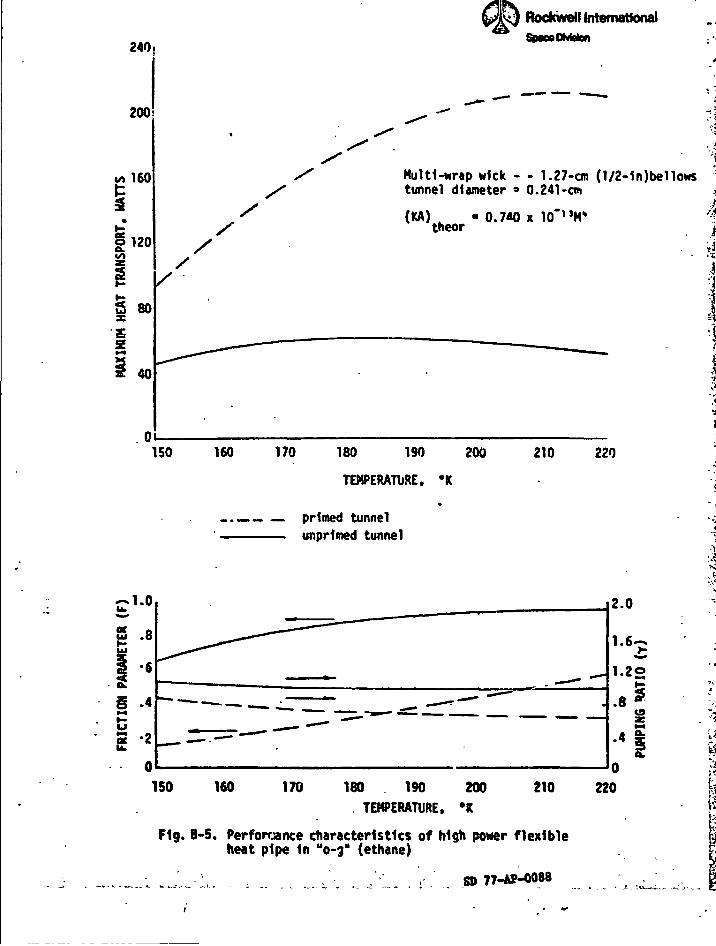
' •
240,
200
160
120
2
80
40
Rockwell InternationalSpnoOMsfen
'
'1 .
Multi-wrap wick - - 1.27-cm (1/2-1n)bello« 'tunnel diameter ° 0.241-cm .«
(KA) ttheor
150 160 170 180 190 200
TEMPERATURE, 'K*
-._ primed tunnelunprlmed tunnel
210 220
I
^
S .8
1 *6Ok
§ .4*4&s "2
2.0
2l-2o
.8(9
.4
150 160 170 180 190 200TEMPERATURE. *K
210 220
Fig. B-5, Performance characteristics of high pxwer flexibleheat pipe In "0-3" (ethane)
SO
i
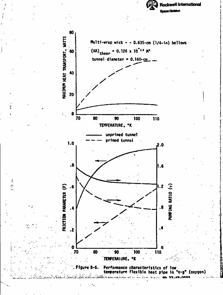
Rockwell to
80
40
»
Multi-wrap wick - - 0.63 5- cm (1/4-1n) bellows
tunnel diameter • 0.160-gg __
1.0
.8
70 80 SO 100TEMPERATURE, -K
—— unpHmed tunnelprimed tunnel
110
S5»*e .2
2.0
1.6
1-2 2
.8
.4
70 80 SO 100TEHPERA1URE, •*
110
Figure B-6. Performance characteristics of lowt temperature flexible heat pipe In "o-g" (oxygen)
i"-(•s
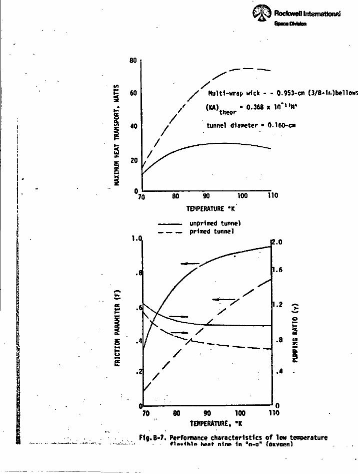
' E3CEEB73 f'K Karl-Si '-!
BockweO fntemattonpj
25
80
60
40
20
i
*
Multi-wrap wick - - 0.953-cm (3/8- 1r.)bellows
(KA) • 0.368 x in"nH»
tunnel diameter • 0.160-cm
70 80 80 100
TD4PERATURE «K
unprlmed tunnel— primed tunnel
110
70 80 90 100 110TEMPERATURE. *K
i-s
>:
1jifi,<
•4
|
j<i
F1g.B-7. Performance characteristics of low temperaturenino 1n °o-o" foxvoen)
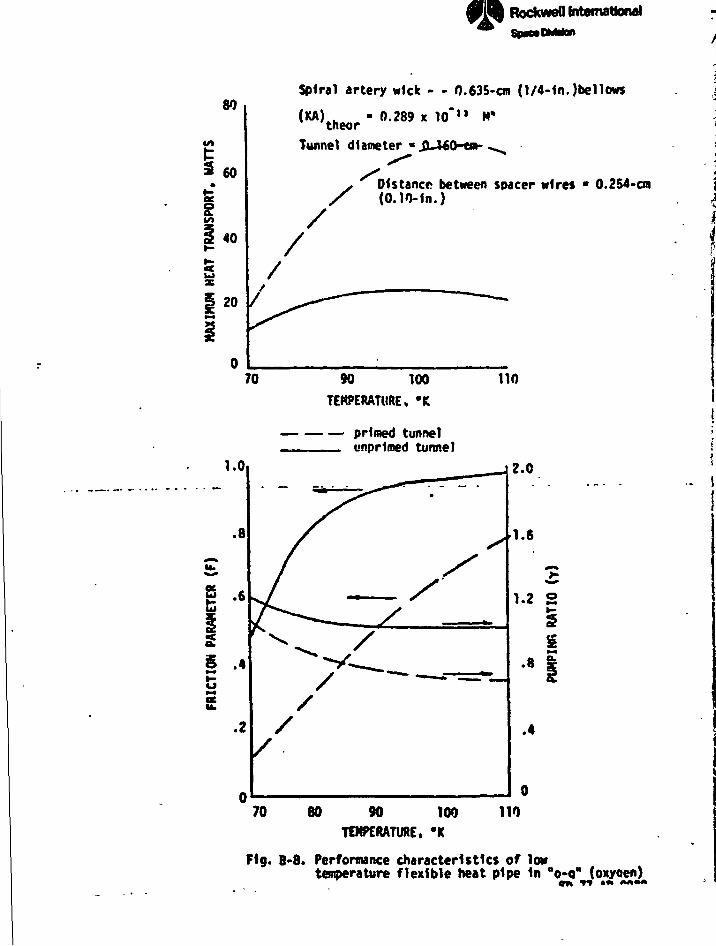
--B
RocfcweU International
TEMPERATURE, 'K
primed tunnel_= unpriced tunnel
70 80 90 100 110TEMPERATURE, *K
\
MAX
IMUM
HEA
T TR
ANSP
ORT
. W
ATTS
IN»
*>
g>
»o
o
o
o
5
Spiral artery wick - - 0.635- cm (1/4-1n.)be11ows
(KA) . - 0.289 x 10"JI M»tneorTunnel diameter «JL460-t»-,
s*
* Distance between spacer wires • 0.254-cm/ (0.10-1n.)
///
10 90 100 110
f3'i
j. i
j
I
' I<i
Fig. B-8. Performance characteristics of lowtemperature flexible heat pipe In "o-o" (oxyoen)
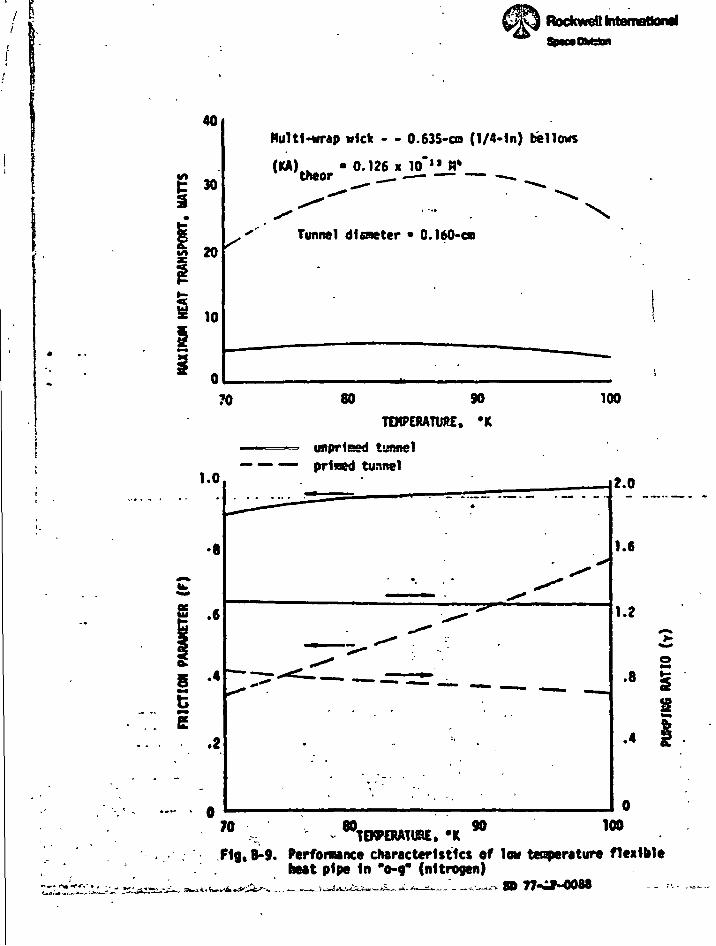
11...— ..- tfescstVcs*} • i
Rockwefl International iI
40
I -
20
10
.
Multi-wrap »fck - - 0.635-co (1/4-ln) follows
("V.r • ••«• «i'-ur . _
Tunnel dlaneter • 0.160-on
70 80 90
TEMPERATURE. 'K
unpriced tunnel
100
— — — prised tunnel
& .6
5 •«EE
.2
1.6
8
.4S
90 100'w x TEKPERATU8E. *KTig. B-9. Perfonaance characteristics of low te^erature flexible
heat pipe In '0-9* (nitrogen)
I'f
4f
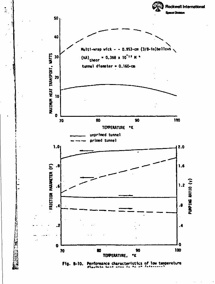
i^^i...- .:.!,_ I •f * i1 v~tr:i,r=r D 3
itemattonaf
50
40
\Multi-wrap wick - - 0.953-OT (3/8-1n)be11ous
(KA)theor • 0.368 I Vf l t H »
tunnel dlueter • 0.16C*OD
70 80 90
TEHPERAT1WE -K
unprlmed tunnel
190
— primed tunnel
*•* au. .8
.6
s.at .4
.2
2.0
1.6
.8 I
.4
70 80 90TDPCRATURE, *K
100
F1g. 8-10. Perfomance characteristics of low tenperaUren««4Ki». k*«» .«.. «- •- -• »-«•——-»