Embed Size (px)
Citation preview
L Series
INSTALLATION GUIDE
INST
ALL
ATI
ON
GU
IDE
Visit www.haikuhome.com/service to watch videos of the installation process.
Installation Guide Topic Page
Technical Specifications 2
Tools Needed 2
Parts 3
Hardware 4
Prepare the Fan Site 5
Install Your Fan 6
READ AND SAVE THESE INSTRUCTIONS
2 REV. A ● © 2016 HAIKU HOME. ALL RIGHTS RESERVED.
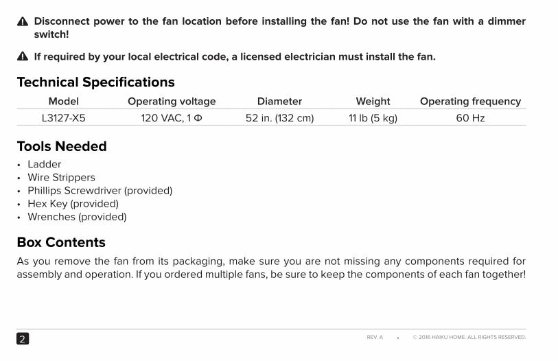
Disconnect power to the fan location before installing the fan! Do not use the fan with a dimmer switch!
If required by your local electrical code, a licensed electrician must install the fan.
Technical SpecificationsModel Operating voltage Diameter Weight Operating frequency
L3127-X5 120 VAC, 1 Φ 52 in. (132 cm) 11 lb (5 kg) 60 Hz
Tools Needed• Ladder• Wire Strippers• Phillips Screwdriver (provided)• Hex Key (provided)• Wrenches (provided)
Box ContentsAs you remove the fan from its packaging, make sure you are not missing any components required for assembly and operation. If you ordered multiple fans, be sure to keep the components of each fan together!
!
!
3HAIKU® HOME ● WWW.HAIKUHOME.COM/SERVICE
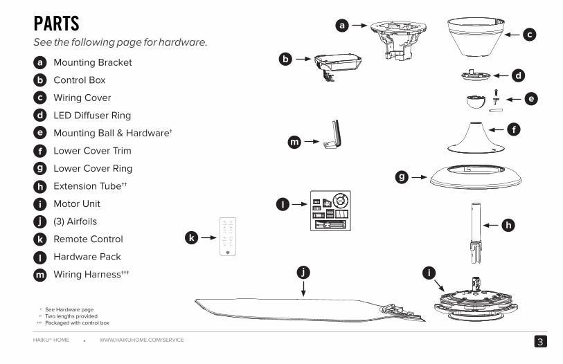
Mounting Bracket
Control Box
Wiring Cover
LED Diffuser Ring
Mounting Ball & Hardware†
Lower Cover Trim
Lower Cover Ring
Extension Tube††
Motor Unit
(3) Airfoils
Remote Control
Hardware Pack
Wiring Harness†††
PARTSSee the following page for hardware.
See Hardware pageTwo lengths providedPackaged with control box
†††
†††
a
b
c
d
e
f
g
h
i
j
k
l
m
a
b
c
d
e
f
g
h
ij
k
l
m
4 REV. A ● © 2016 HAIKU HOME. ALL RIGHTS RESERVED.
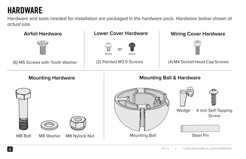
HARDWAREHardware and tools needed for installation are packaged in the hardware pack. Hardware below shown at actual size.
Mounting Hardware
M8 Bolt M8 Washer M8 Nylock Nut
Airfoil Hardware
(6) M5 Screws with Tooth Washer
Wiring Cover Hardware
(4) M4 Socket Head Cap Screws
Lower Cover Hardware
Mounting Ball & Hardware
Steel Pin
Wedge 4 mm Self-TappingScrew
Mounting Ball
(2) Painted M3.5 Screws
orBlackWhite
5HAIKU® HOME ● WWW.HAIKUHOME.COM/SERVICE
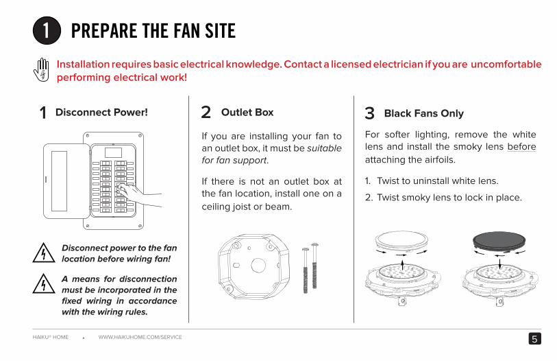
1 PREPARE THE FAN SITEInstallation requires basic electrical knowledge. Contact a licensed electrician if you are uncomfortable performing electrical work!
321 Disconnect Power!
If you are installing your fan to an outlet box, it must be suitable for fan support.
If there is not an outlet box at the fan location, install one on a ceiling joist or beam.
For softer lighting, remove the white lens and install the smoky lens before attaching the airfoils.
1. Twist to uninstall white lens.
2. Twist smoky lens to lock in place.
Disconnect power to the fan location before wiring fan!
A means for disconnection must be incorporated in the fixed wiring in accordance with the wiring rules.
Outlet Box Black Fans Only
6 REV. A ● © 2016 HAIKU HOME. ALL RIGHTS RESERVED.
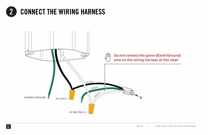
2 CONNECT THE WIRING HARNESS
aAC HOT/L1
AC NEUTRAL/L2
GREEN
WHITE
BLACK
PE/EARTH GROUND
Do not connect the green (Earth/Ground) wire on the wiring harness at this step!
7HAIKU® HOME ● WWW.HAIKUHOME.COM/SERVICE
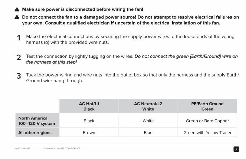
Make sure power is disconnected before wiring the fan!
Do not connect the fan to a damaged power source! Do not attempt to resolve electrical failures on your own. Consult a qualified electrician if uncertain of the electrical installation of this fan.
Make the electrical connections by securing the supply power wires to the loose ends of the wiring harness (a) with the provided wire nuts.
Test the connection by lightly tugging on the wires. Do not connect the green (Earth/Ground) wire on the harness at this step!
Tuck the power wiring and wire nuts into the outlet box so that only the harness and the supply Earth/Ground wire hang through.
AC Hot/L1Black
AC Neutral/L2White
PE/Earth GroundGreen
North America100–120 V system
Black White Green or Bare Copper
All other regions Brown Blue Green with Yellow Tracer
!
!
3
2
1
8 REV. A ● © 2016 HAIKU HOME. ALL RIGHTS RESERVED.
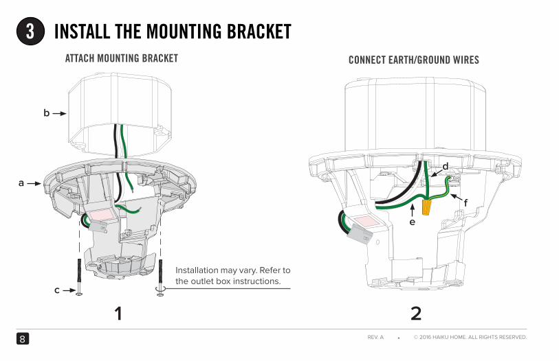
INSTALL THE MOUNTING BRACKET3
b
a
c
Installation may vary. Refer to the outlet box instructions.
1 2
CONNECT EARTH/GROUND WIRESATTACH MOUNTING BRACKET
dd
e
f
slope
open side
slope
9HAIKU® HOME ● WWW.HAIKUHOME.COM/SERVICE
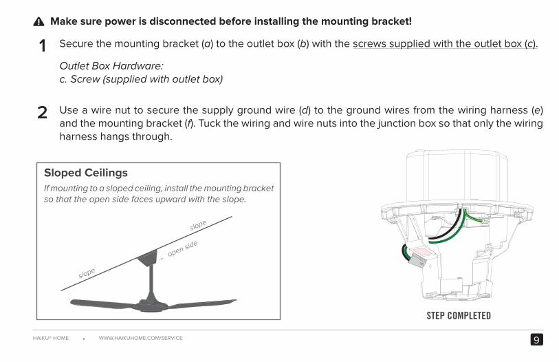
Make sure power is disconnected before installing the mounting bracket!
Secure the mounting bracket (a) to the outlet box (b) with the screws supplied with the outlet box (c).
Outlet Box Hardware:c. Screw (supplied with outlet box)
Use a wire nut to secure the supply ground wire (d) to the ground wires from the wiring harness (e) and the mounting bracket (f). Tuck the wiring and wire nuts into the junction box so that only the wiring harness hangs through.
!
STEP COMPLETED
Sloped CeilingsIf mounting to a sloped ceiling, install the mounting bracket so that the open side faces upward with the slope.
2
1
10 REV. A ● © 2016 HAIKU HOME. ALL RIGHTS RESERVED.
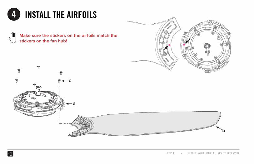
INSTALL THE AIRFOILS4
b
c
a
Make sure the stickers on the airfoils match the stickers on the fan hub!
11HAIKU® HOME ● WWW.HAIKUHOME.COM/SERVICE
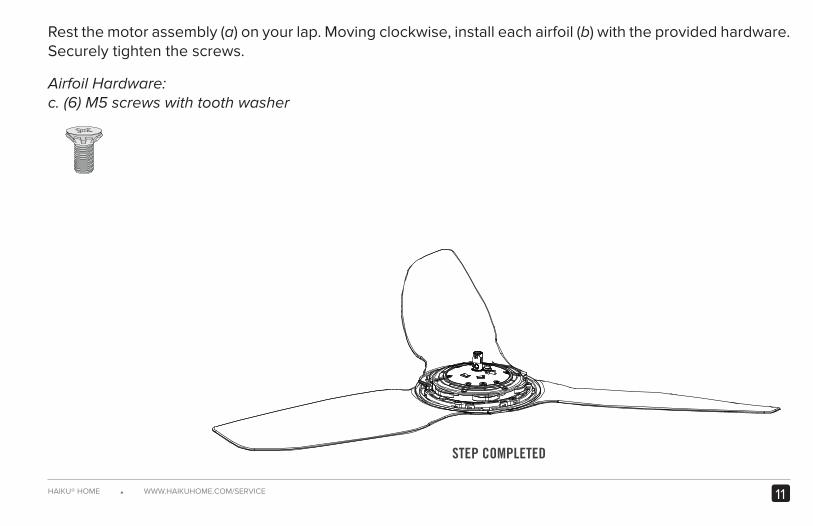
Rest the motor assembly (a) on your lap. Moving clockwise, install each airfoil (b) with the provided hardware. Securely tighten the screws.
Airfoil Hardware:c. (6) M5 screws with tooth washer
STEP COMPLETED

12 REV. A ● © 2016 HAIKU HOME. ALL RIGHTS RESERVED.
INSTALL THE LOWER EARTH/GROUND WIRE5
a
c
1 2
b
d
SECURE EARTH/GROUND WIREPOSITION EXTENSION TUBE
13HAIKU® HOME ● WWW.HAIKUHOME.COM/SERVICE
STEP COMPLETED
2
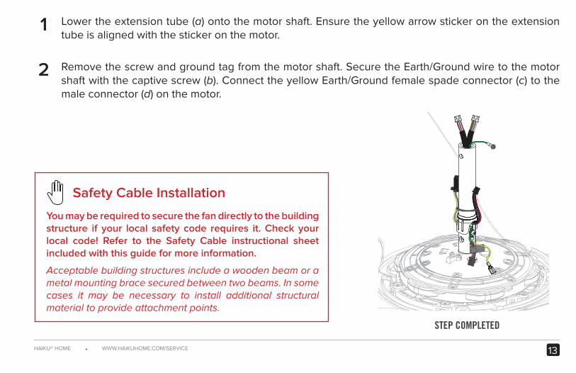
1 Lower the extension tube (a) onto the motor shaft. Ensure the yellow arrow sticker on the extension tube is aligned with the sticker on the motor.
Remove the screw and ground tag from the motor shaft. Secure the Earth/Ground wire to the motor shaft with the captive screw (b). Connect the yellow Earth/Ground female spade connector (c) to the male connector (d) on the motor.
Safety Cable Installation
You may be required to secure the fan directly to the building structure if your local safety code requires it. Check your local code! Refer to the Safety Cable instructional sheet included with this guide for more information.
Acceptable building structures include a wooden beam or a metal mounting brace secured between two beams. In some cases it may be necessary to install additional structural material to provide attachment points.
14 REV. A ● © 2016 HAIKU HOME. ALL RIGHTS RESERVED.
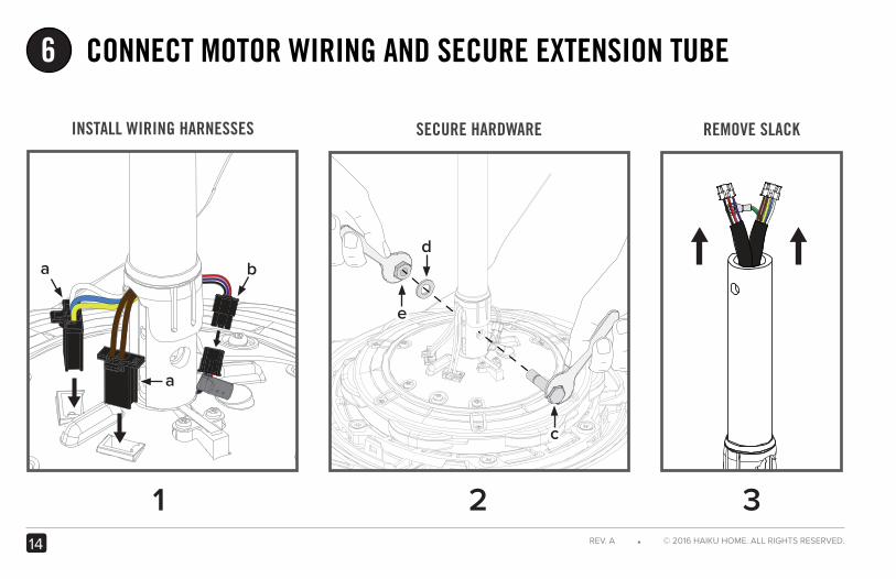
6 CONNECT MOTOR WIRING AND SECURE EXTENSION TUBE
1 32
d
SECURE HARDWARE REMOVE SLACKINSTALL WIRING HARNESSES
a
a
b
c
e
15HAIKU® HOME ● WWW.HAIKUHOME.COM/SERVICE
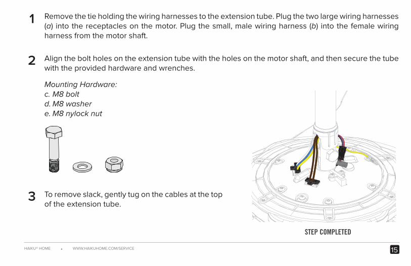
Remove the tie holding the wiring harnesses to the extension tube. Plug the two large wiring harnesses (a) into the receptacles on the motor. Plug the small, male wiring harness (b) into the female wiring harness from the motor shaft.
Align the bolt holes on the extension tube with the holes on the motor shaft, and then secure the tube with the provided hardware and wrenches.
Mounting Hardware:c. M8 boltd. M8 washere. M8 nylock nut
To remove slack, gently tug on the cables at the top of the extension tube.
STEP COMPLETED
2
1
3
16 REV. A ● © 2016 HAIKU HOME. ALL RIGHTS RESERVED.
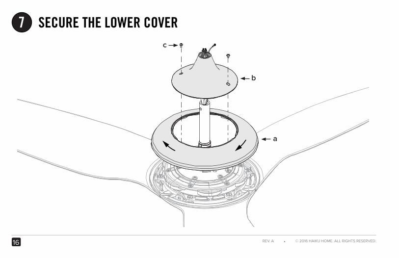
SECURE THE LOWER COVERc
7
b
a
STEP COMPLETED
17HAIKU® HOME ● WWW.HAIKUHOME.COM/SERVICE
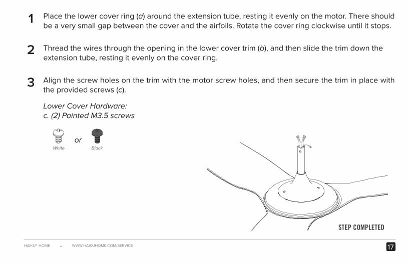
Place the lower cover ring (a) around the extension tube, resting it evenly on the motor. There should be a very small gap between the cover and the airfoils. Rotate the cover ring clockwise until it stops.
Thread the wires through the opening in the lower cover trim (b), and then slide the trim down the extension tube, resting it evenly on the cover ring.
Align the screw holes on the trim with the motor screw holes, and then secure the trim in place with the provided screws (c).
Lower Cover Hardware:c. (2) Painted M3.5 screws
2
1
3
orBlackWhite
18 REV. A ● © 2016 HAIKU HOME. ALL RIGHTS RESERVED.
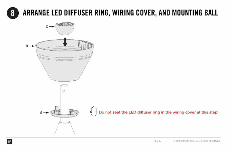
ARRANGE LED DIFFUSER RING, WIRING COVER, AND MOUNTING BALL8
a
b
c
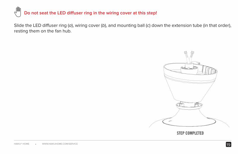
Do not seat the LED diffuser ring in the wiring cover at this step!
19HAIKU® HOME ● WWW.HAIKUHOME.COM/SERVICE
Slide the LED diffuser ring (a), wiring cover (b), and mounting ball (c) down the extension tube (in that order), resting them on the fan hub.
STEP COMPLETED
Do not seat the LED diffuser ring in the wiring cover at this step!
20 REV. A ● © 2016 HAIKU HOME. ALL RIGHTS RESERVED.
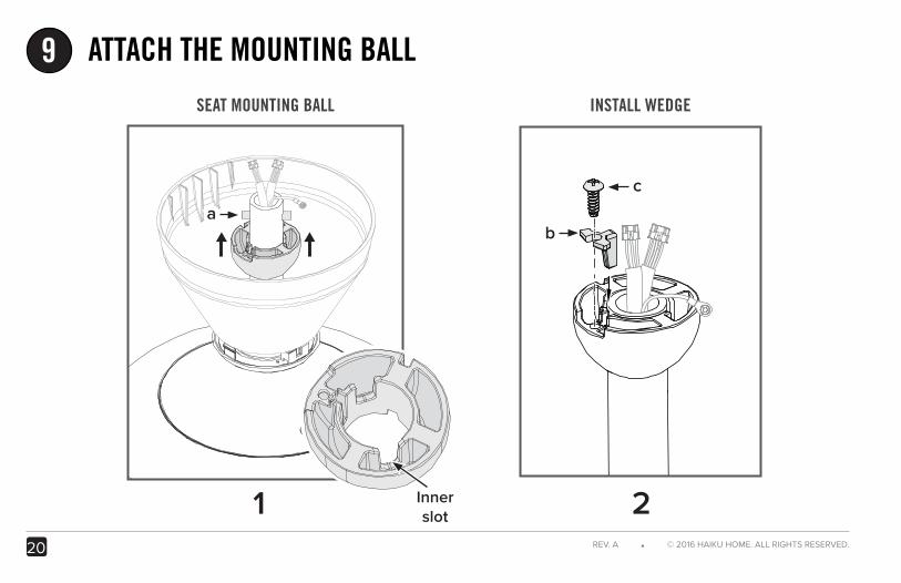
ATTACH THE MOUNTING BALL9
c
ab
Inner slot
SEAT MOUNTING BALL
21
INSTALL WEDGE
21HAIKU® HOME ● WWW.HAIKUHOME.COM/SERVICE
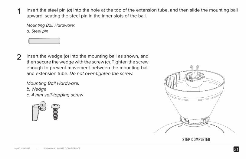
Insert the steel pin (a) into the hole at the top of the extension tube, and then slide the mounting ball upward, seating the steel pin in the inner slots of the ball.
Mounting Ball Hardware:a. Steel pin
Insert the wedge (b) into the mounting ball as shown, and then secure the wedge with the screw (c). Tighten the screw enough to prevent movement between the mounting ball and extension tube. Do not over-tighten the screw.
Mounting Ball Hardware:b. Wedgec. 4 mm self-tapping screw
STEP COMPLETED
2
1
22 REV. A ● © 2016 HAIKU HOME. ALL RIGHTS RESERVED.
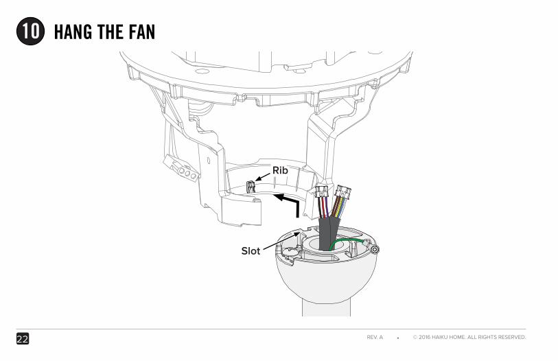
HANG THE FAN 10
Rib
Slot
23HAIKU® HOME ● WWW.HAIKUHOME.COM/SERVICE
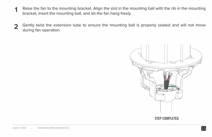
Raise the fan to the mounting bracket. Align the slot in the mounting ball with the rib in the mounting bracket, insert the mounting ball, and let the fan hang freely.
Gently twist the extension tube to ensure the mounting ball is properly seated and will not move during fan operation.
STEP COMPLETED
2
1
24 REV. A ● © 2016 HAIKU HOME. ALL RIGHTS RESERVED.
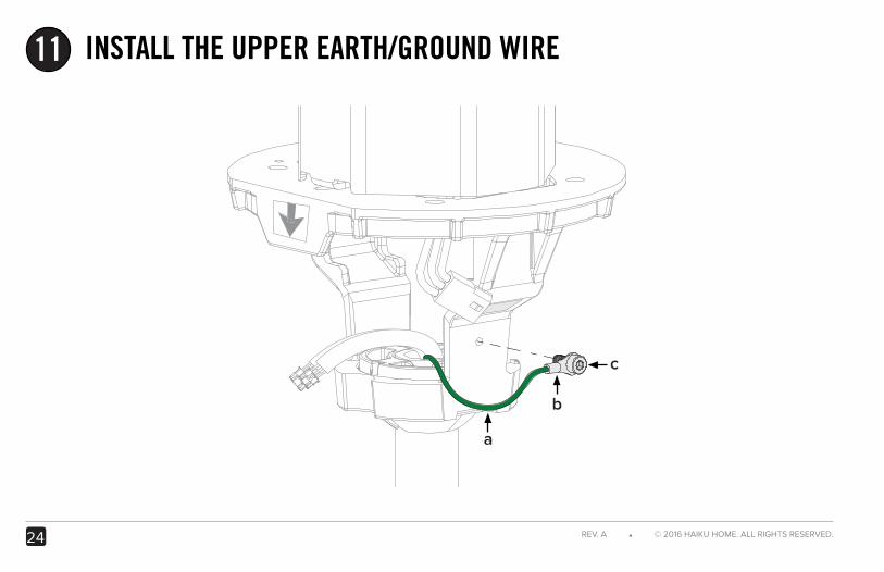
INSTALL THE UPPER EARTH/GROUND WIRE11
b
c
a
25HAIKU® HOME ● WWW.HAIKUHOME.COM/SERVICE
STEP COMPLETED
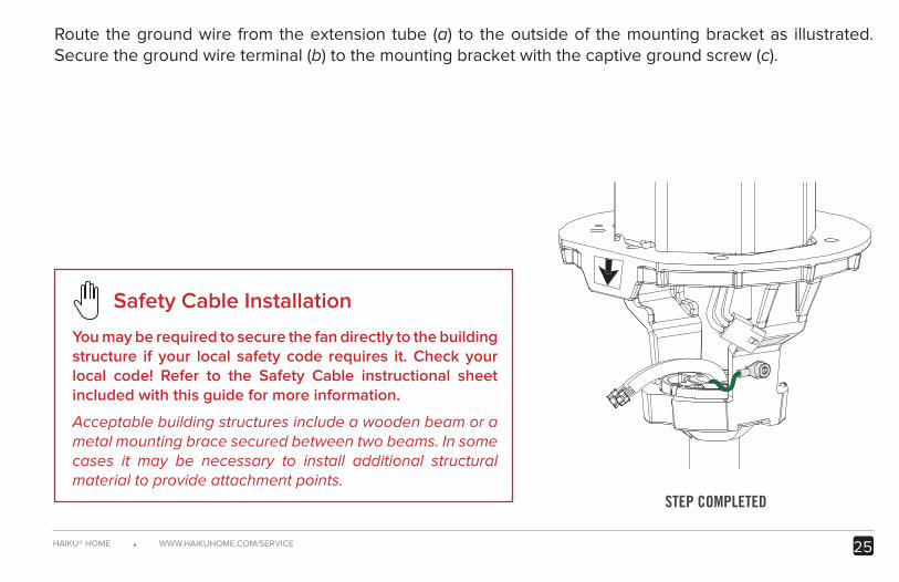
Safety Cable Installation
You may be required to secure the fan directly to the building structure if your local safety code requires it. Check your local code! Refer to the Safety Cable instructional sheet included with this guide for more information.
Acceptable building structures include a wooden beam or a metal mounting brace secured between two beams. In some cases it may be necessary to install additional structural material to provide attachment points.
Route the ground wire from the extension tube (a) to the outside of the mounting bracket as illustrated. Secure the ground wire terminal (b) to the mounting bracket with the captive ground screw (c).
26 REV. A ● © 2016 HAIKU HOME. ALL RIGHTS RESERVED.
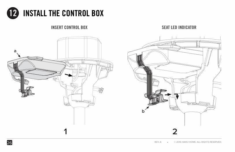
INSTALL THE CONTROL BOX12
a
1 2
b
INSERT CONTROL BOX SEAT LED INDICATOR
27HAIKU® HOME ● WWW.HAIKUHOME.COM/SERVICE
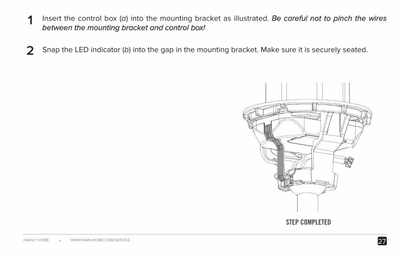
Insert the control box (a) into the mounting bracket as illustrated. Be careful not to pinch the wires between the mounting bracket and control box!
Snap the LED indicator (b) into the gap in the mounting bracket. Make sure it is securely seated.
STEP COMPLETED
2
1
e
d
28 REV. A ● © 2016 HAIKU HOME. ALL RIGHTS RESERVED.
a
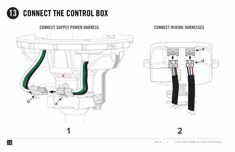
CONNECT THE CONTROL BOX13
1 2
b
c
CONNECT SUPPLY POWER HARNESS CONNECT WIRING HARNESSES
29HAIKU® HOME ● WWW.HAIKUHOME.COM/SERVICE
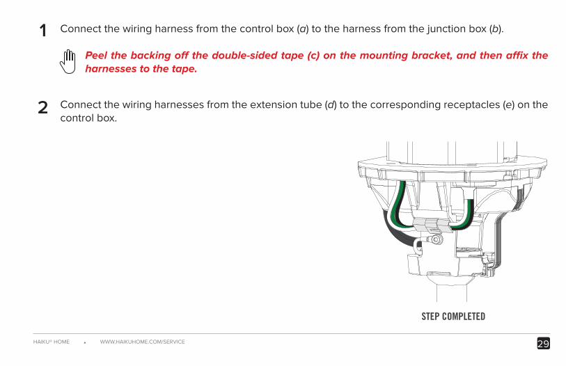
Connect the wiring harness from the control box (a) to the harness from the junction box (b).
Peel the backing off the double-sided tape (c) on the mounting bracket, and then affix the harnesses to the tape.
Connect the wiring harnesses from the extension tube (d) to the corresponding receptacles (e) on the control box.
STEP COMPLETED
1
2
30 REV. A ● © 2016 HAIKU HOME. ALL RIGHTS RESERVED.
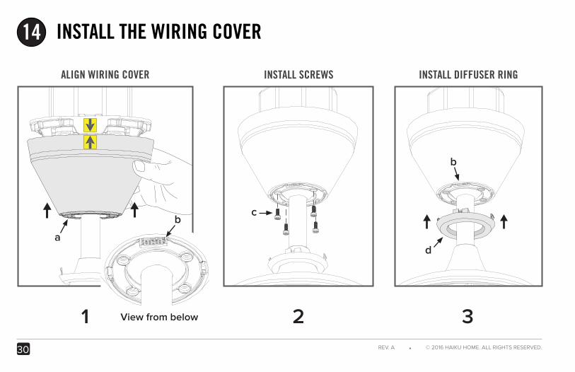
INSTALL THE WIRING COVER14
1 2
a
c
d
View from below
bb
ALIGN WIRING COVER INSTALL SCREWS INSTALL DIFFUSER RING
3
b
31HAIKU® HOME ● WWW.HAIKUHOME.COM/SERVICE
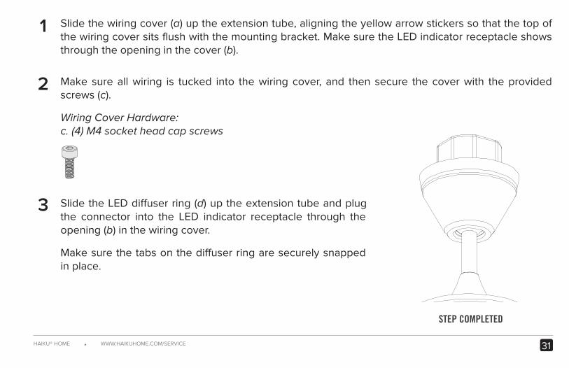
Slide the wiring cover (a) up the extension tube, aligning the yellow arrow stickers so that the top of the wiring cover sits flush with the mounting bracket. Make sure the LED indicator receptacle shows through the opening in the cover (b).
Make sure all wiring is tucked into the wiring cover, and then secure the cover with the provided screws (c).
Wiring Cover Hardware:c. (4) M4 socket head cap screws
Slide the LED diffuser ring (d) up the extension tube and plug the connector into the LED indicator receptacle through the opening (b) in the wiring cover.
Make sure the tabs on the diffuser ring are securely snapped in place.
1
2
STEP COMPLETED
3
32 REV. A ● © 2016 HAIKU HOME. ALL RIGHTS RESERVED.
TEST THE FAN15
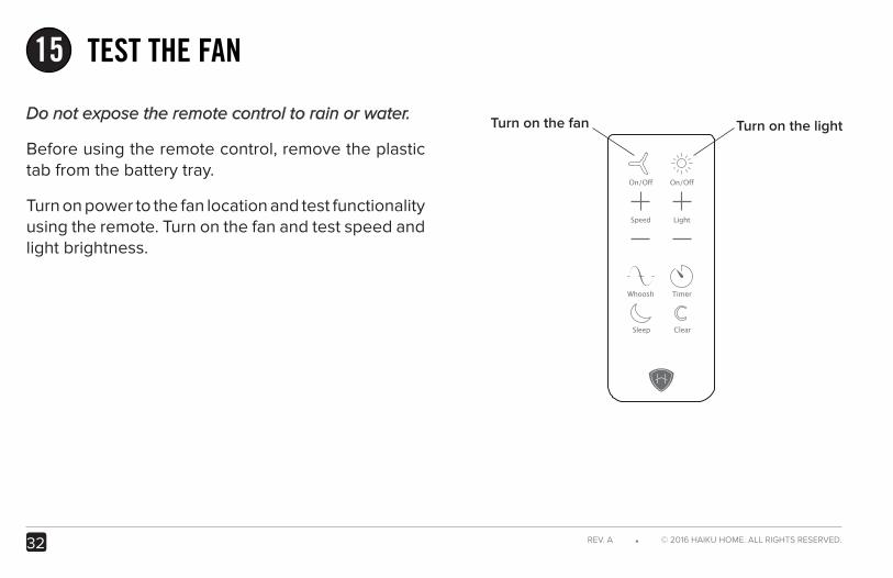
Turn on the lightTurn on the fanDo not expose the remote control to rain or water.
Before using the remote control, remove the plastic tab from the battery tray.
Turn on power to the fan location and test functionality using the remote. Turn on the fan and test speed and light brightness.

© 2016 Haiku Home
The information contained in this document is subject to change without notice. May be protected by one or more patents listed at www.bigasssolutions.com/patents
Haiku is a trademark of Delta T Corporation, registered in the U.S. and/or other countries.

L Series
INSTALLATION GUIDE
INST
ALL
ATI
ON
GU
IDE
HKU-INST-101-ENG-01