Embed Size (px)
Citation preview

1

• Phase partitioning: in multi‐phase systems, materials are distributed with some ratio between the phases at equilibrium – Recall Henry’s law (gas‐liquid partitioning): /
ex) At 1 atm, 20°C, the saturation concentration of dissolved oxygen in pure water is 9.08 mg/L (0.208 atm partial pressure of O2 in gas phase ↔ 9.08 mg/L O2 in aqueous solution)
2

• Transfer of material from one homogeneous phase to another• Interphase mass transfer occurs towards equilibrium• Time as a factor: it takes some time for the mass transfer
processes to occur such that equilibrium is established
ex) Drying clothesphase partitioning: moisture wetting the clothes vs. moisture in the ambient airequilibrium: almost no moisture in the clothes because the amount of ambient air is almost infinitetime as a factor: it takes some time (~1 day) for the clothes to dry
3

4
Type of reactor Phase equilibria Application
Absorption Gas → liquid Addition of gases to water (e.g., O2), NH3 scrubbing in acid
Adsorption Gas → solidLiquid→ solid
Removal of organics with activated carbonRemoval or organics with activated carbon, dechlorination
Desorption Solid→ liquidSolid → gas
Sediment scrubbingReactivation of spent activated carbon
Drying (evaporation)
Liquid → gas Drying of sludge
Gas stripping Liquid → gas Removal of gases (e.g., CO2, H2S, NH3, VOCs)
Ion exchange Liquid → solid Selective removal of chemical constituents, demineralization

• Fundamental mechanism: molecular diffusion
= mass flux; rate of mass transfer per unit area per unit time [ML‐2T‐1]= molecular diffusion coefficient [L2T‐1]
= concentration [ML‐3]= distance [L]
Fick’s 1st law of diffusion
5
Driving force: concentration gradient

bulk gas bulk liquidliquid film
gas film
distance
conc. or partial P
Assumptions1) Resistance to interphase mass transfer in stagnant films2) Equilibrium obtained at the interphase3) Uniform concentration in bulk fluids 4) Linear concentration gradients in the stagnant film (steady state diffusion)
Direction of mass transfer
Hu = unitless Henry’s law constant
6
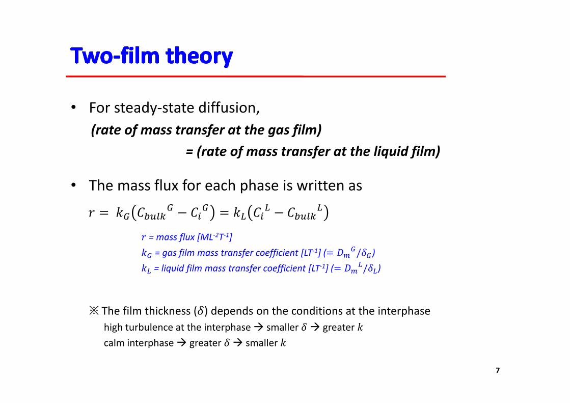
• For steady‐state diffusion, (rate of mass transfer at the gas film)
= (rate of mass transfer at the liquid film)
= mass flux [ML‐2T‐1]= gas film mass transfer coefficient [LT‐1] ( / )= liquid film mass transfer coefficient [LT‐1] ( / )
• The mass flux for each phase is written as
※ The film thickness ( ) depends on the conditions at the interphasehigh turbulence at the interphase smaller greater calm interphase greater smaller
7

• Overall mass transfer coefficient
The film thickness (δG or δL) and the interphase concentration (CiG or CiL) are not easy to determine
Using liquid phase as a reference, the mass flux is written as
Use overall mass transfer coefficient with easily measurable values
r = mass flux [ML‐2T‐1]KL = overall liquid mass transfer coefficient [LT‐1]CsL = liquid concentration of the constituent in equilibrium with the gas concentration of the constituent in the bulk phase [ML‐3] (=CbulkG/Hu)
8

• Overall mass transfer coefficient
or 1 1 1
9

1 1 1
‐ In most cases, 1 < (kG/kL) <300‐ For volatile, less water soluble compounds (high Hu), water‐air mass
transfer is usually controlled by liquid film (ex: O2, Hu ≈ 30)‐ For less volatile, highly water soluble compounds (low Hu), water‐air
mass transfer is usually controlled by gas film (ex: phenol, Hu ≈ 0.00003)
10

• Modeling concentration change by mass transfer‐ Flux = (mass transferred) / (area) / (time)
‐ When the bulk gas concentration is constant, change in bulk liquid concentration is represented as:
rv = rate of mass transfer [ML‐3T‐1]A= area through which mass is transferred [L2]V = bulk liquid volume [L3]Cs = liquid concentration in equilibrium with bulk gas concentration [ML‐3]C = liquid concentration at time tKLa = volumetric mass transfer coefficient [T‐1]
11

• Absorption of gas in a batch reactor
C
V(rate of accumulation) = (rate of inflow) – (rate of outflow) + (rate of generation)
12
• Desorption of gas in a batch reactor

Q: Secondary effluent is placed in a storage basin for reuse. If the initial DO concentration is 1.5 mg/L, estimate the time required for the DO concentration to increase to 8.5 mg/L due to surface reaeration. The surface area of the storage basin is 400 m2 and the depth is 3 m. Assume the KL value for oxygen is 0.03 m/hr. Use the saturation DO concentration of 9.09 mg/L at 20°C.
13

14

• Usually applied as a unit process for tertiary treatment or for supplementary processes
• Biological vs. chemical processes– Biological processes as a major unit for the current wastewater treatment
• Biological processes – less reliable but more cost‐effective, benign products• Chemical processes – more reliable but concern with chemical cost & sludge disposal Biological processes may be more suitable for concentrated treatment systems
– Wastewater management in the next generation – decentralized treatment??• Reconsideration of chemical processes needed as significant limitations of biological
processes are expected because of..– Significant variations in flowrates & loadings at small scale– Small‐scale facilities cannot be maintained by trained personnel & in a continuous
manner
15

16
Processes Application
Advanced oxidation Removal of refractory organic compounds
Chemical coagulation Chemical destabilization of particles in wastewater to bring about their aggregation during flocculation
Chemical disinfection Disinfection with chlorine, chlorine compounds, bromine, and ozoneControl of odors
Chemical neutralization Control of pH
Chemical oxidation Removal of BOD, grease, etc.Removal of ammoniumDestruction of microorganismsControl of odors in sewers, pump stations, and treatment plantsRemoval of resistant organic compounds

17
Processes Application
Chemical precipitation Enhanced removal of TSS and BOD in primary sedimentation facilitiesRemoval of phosphorousRemoval of ammoniumRemoval of heavy metalsPhysical‐chemical treatmentCorrosion control in sewers due to H2S
Chemical scale control Control of scaling due to calcium carbonate and related compounds
Chemical stabilization Stabilization of treated effluents
Ion exchange Removal of ammonium, heavy metals, total dissolved solidsRemoval of organic compounds

• External substances are often added– There is often a net increase in certain dissolved wastewater constituentsex1) addition of coagulants increase in wastewater TDSex2) addition of chlorine for disinfection: increase in TDS and generation of disinfection byproducts
• Generation of chemical precipitation sludge– Handling, treatment, and disposal of the chemical sludge requires additional
cautions
• Cost of chemicals & sustainability
18

• Colloidal particles in wastewater typically have a net negative charge and thus, at stabilized condition
• Coagulation vs. flocculation– Coagulation
• A chemical process to destabilize the particles by changing the surface properties so that particles can stick together when they collide
• But quite often used as a term that includes mechanisms involved both in chemical destabilization of particles and growth in particle size
19
http://www.wrights‐trainingsite.com/ WT%20coagfloconb.html
– Flocculation• A physical process to create conditions (by gentle mixing) that allow particles to grow in size

20
http://www.wrights‐trainingsite.com/ WT%20coagfloconb.html
http://www.kconsultation.com

• The electrical double layer
21
– Charged particles in water are surrounded by ions of opposite charge
– A compact layer (Stern layer) + a diffuse layer
Stern model of electrical double
layer

22
Definition sketch for particle‐particle interactions based on the repulsion due to particle surface charge and van der Waals forces of attraction. N = concentration; z = charge.

• Forces between particles– Electrical force (repulsion; when the particles are of the same charge)– van der Waals force (attraction)– Net energy = electrical force + van der Waals force– The energy barrier (maximum repulsive force of the net energy) has to be
overcome for particles to be attached to each other
• How to reduce the energy barrier?– Reduce the particle surface charge by attachment of ions of opposite charge
• Charge neutralization
– Add electrolytes to reduce the electrical double layer thickness• Ionic strength ↑ → Compression of electrical double layer
23

• Mechanisms of particle removal by coagulation– Charge neutralization– Compression of electrical double layer– Inter‐particle bridging– Enmeshment in sweep floc
• Use of polyelectrolytes– Ions of multiple charge are good at charge neutralization & electrical double
layer compression (+1 << +2 << +3)– Commonly used coagulants: Al3+ or Fe3+ salts(Alum, Al2(SO4)3∙14H2O: most common)
24

![TMA4267LinearStatisticalModelsV2017(L15) - NTNU · TMA4267LinearStatisticalModelsV2017(L15) Part3: Hypothesistestingandanalysisofvariance One-andtwo-wayANOVA[H:8.1.1] MetteLangaas](https://img.pdfslide.net/doc/110x75/5d4acde988c9939a3e8bb841/tma4267linearstatisticalmodelsv2017l15-ntnu-tma4267linearstatisticalmodelsv2017l15.jpg)