Embed Size (px)
Citation preview

Service Manual
L22-236 Rev. 2 (06/11)
IMPORTANT FOR FUTURE REFERENCE
Please complete this information and retain this manualfor the life of the equipment:
Model #: ___________________________
Serial #: ___________________________
Date Purchased: ____________________
EN
GL
ISH
MGII: McDonald’s Full and Split Gas Fryerswith and without Filter
D
EIFITRE
C
DE S I G
N
C IRE T IF E D
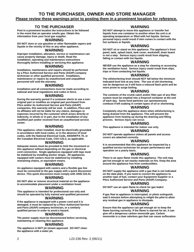
TO THE PURCHASER, OWNER AND STORE MANAGERPlease review these warnings prior to posting them in a prominent location for reference.
2 L22-236 Rev. 2 (06/11)
TO THE PURCHASERPost in a prominent location the instructions to be followedin the event that an operator smells gas. Obtain thisinformation from your local gas supplier.
WARNINGDO NOT store or use gasoline or other flammable vapors andliquids in the vicinity of this or any other appliance.
WARNINGImproper installation, alteration, service or maintenance cancause property damage, injury or death. Read theinstallation, operating and maintenance instructionsthoroughly before installing or servicing this appliance.
WARNINGInstallation, maintenance and repairs should be performedby a Pitco Authorized Service and Parts (ASAP) companytechnician or other qualified personnel. Installation,maintenance or repairs by unauthorized and unqualifiedpersonnel will void the warranty.
WARNINGInstallation and all connections must be made according tonational and local regulations and codes in force.
WARNINGDuring the warranty period if a customer elects to use a non-original part or modifies an original part purchased fromPitco and/or its Authorized Service and Parts (ASAP)companies, this warranty will be void. In addition, Pitco andits affiliates will not be liable for any claims, damages orexpenses incurred by the customer which arises directly orindirectly, in whole or in part, due to the installation of anymodified part and/or received from an unauthorized servicecenter.
WARNINGThis appliance, when installed, must be electrically groundedin accordance with local codes, or in the absence of localcodes, with the National Electrical Code, ANSI/NFPA 70, orthe Canadian Electrical Code, CSA C22.2, as applicable.
WARNINGAdequate means must be provided to limit the movement orthis appliance without depending on the gas or electricalcord connection. Single appliances equipped with legs mustbe stabilized by installing anchor straps. All appliancesequipped with casters must be stabilized by installingrestraining chains, or equivalent means.
WARNINGAn appliance equipped with casters and a flexible gas linemust be connected to the gas supply with a quick disconnectdevice. This quick disconnect must comply with ANSI Z24.41.
WARNINGDO NOT alter or remove structural material on the applianceto accommodate placement under a ventilation hood.
WARNINGThis appliance is intended for professional use only andshould be operated by fully trained and qualified personnel.
WARNINGIf the appliance is equipped with a power cord and it isdamaged, it must be replaced by a Pitco Authorized Serviceand Parts (ASAP) company technician, or a similarlyqualified person in order to avoid a hazard.
WARNINGThe power supply must be disconnected before servicing,maintaining or cleaning this appliance.
WARNINGThe appliance is NOT jet stream approved. DO NOT cleanthe appliance with a water jet.
WARNINGDO NOT attempt to move this appliance or transfer hotliquids from one container to another when the unit is atoperating temperature or filled with hot liquids. Seriouspersonal injury could result if skin comes in contact with thehot surfaces or liquids.
WARNINGDO NOT sit or stand on this appliance. The appliance’s frontpanel, tank, splash back, tank cover, workshelf, drain boardis not a step. Serious injury could result from slipping,falling or contact with hot liquids.
WARNINGNEVER use the appliance as a step for cleaning or accessingthe ventilation hood. Serious injury could result from slips,trips or from contacting hot liquids.
WARNINGThe oil/shortening level should NOT fall below the minimumindicated level line at any time. The use of old shorteningcan be dangerous as it will have a reduced flash point and bemore prone to surge boiling.
WARNINGThe contents of the crumb catch and/or filter pan of any filtersystem must be emptied into a fireproof container at the endof each day. Some food particles can spontaneouslycombust if left soaking in certain types of oil or shortening.
WARNINGCompletely shut the appliance down when oil/shortening isbeing drained from the appliance. This will prevent theappliance from heating up during the draining and fillingprocess. Serious injury can occur.
WARNINGThis appliance is intended for indoor use only.
WARNINGDO NOT operate appliance unless all panels and accesscovers are attached correctly.
WARNINGIt is recommended that this appliance be inspected by aqualified service technician for proper performance andoperation on a yearly basis.
WARNINGThere is an open flame inside this appliance. The unit mayget hot enough to set nearby materials on fire. Keep the areaaround the appliance free from combustibles.
WARNINGDO NOT supply the appliance with a gas that is not indicatedon the data plate. If you need to convert the appliance toanother type of fuel, contact your Equipment Supplier or aPitco Authorized Service and Parts (ASAP) Company.
WARNINGDO NOT use an open flame to check for gas leaks!
WARNINGIf gas flow to appliance is interrupted, or pilots extinguish,wait 5 minutes before attempting to relight the pilot to allowany residual gas in appliance to dissipate.
WARNINGEnsure that the appliance can get enough air to keep theflame burning correctly. If the flame is starved for air, it cangive off a dangerous carbon monoxide gas. Carbonmonoxide is a clear odorless gas that can cause suffocation.
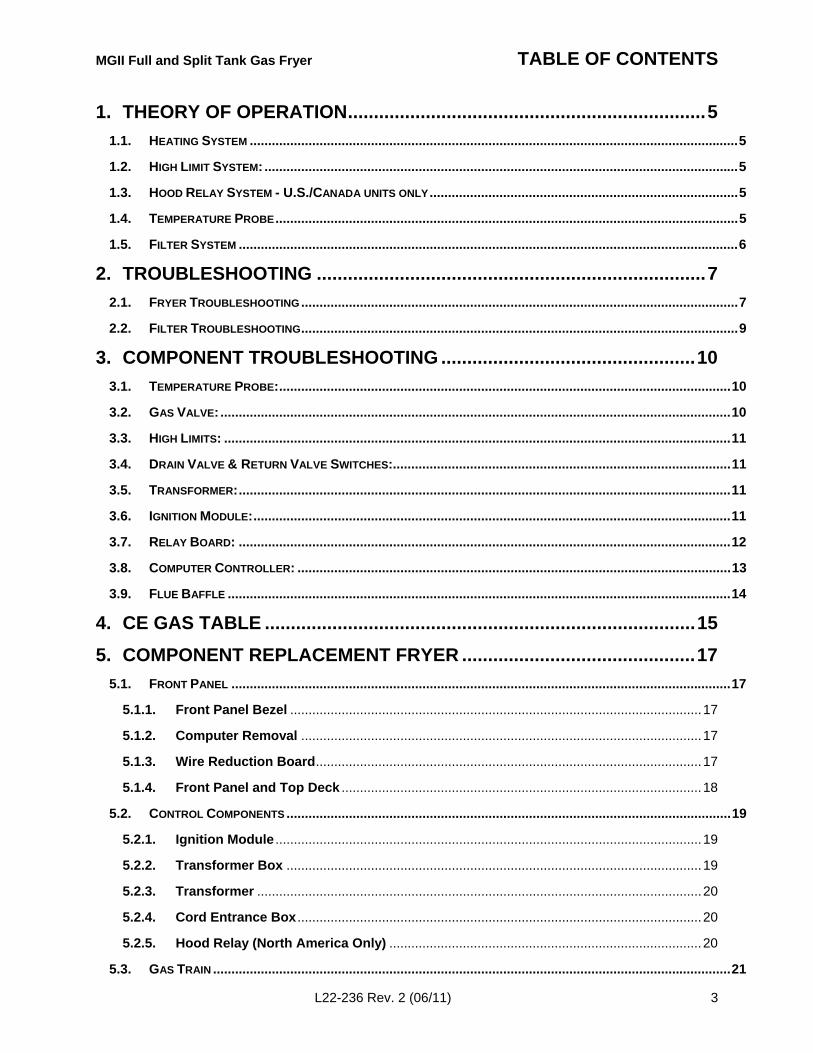
MGII Full and Split Tank Gas Fryer TABLE OF CONTENTS
L22-236 Rev. 2 (06/11) 3
1. THEORY OF OPERATION.....................................................................5
1.1. HEATING SYSTEM .....................................................................................................................................5
1.2. HIGH LIMIT SYSTEM: .................................................................................................................................5
1.3. HOOD RELAY SYSTEM - U.S./CANADA UNITS ONLY....................................................................................5
1.4. TEMPERATURE PROBE..............................................................................................................................5
1.5. FILTER SYSTEM ........................................................................................................................................6
2. TROUBLESHOOTING ...........................................................................7
2.1. FRYER TROUBLESHOOTING.......................................................................................................................7
2.2. FILTER TROUBLESHOOTING.......................................................................................................................9
3. COMPONENT TROUBLESHOOTING .................................................10
3.1. TEMPERATURE PROBE:...........................................................................................................................10
3.2. GAS VALVE: ...........................................................................................................................................10
3.3. HIGH LIMITS: ..........................................................................................................................................11
3.4. DRAIN VALVE & RETURN VALVE SWITCHES:............................................................................................11
3.5. TRANSFORMER:......................................................................................................................................11
3.6. IGNITION MODULE:..................................................................................................................................11
3.7. RELAY BOARD: ......................................................................................................................................12
3.8. COMPUTER CONTROLLER: ......................................................................................................................13
3.9. FLUE BAFFLE .........................................................................................................................................14
4. CE GAS TABLE ...................................................................................15
5. COMPONENT REPLACEMENT FRYER .............................................17
5.1. FRONT PANEL ........................................................................................................................................17
5.1.1. Front Panel Bezel ................................................................................................................17
5.1.2. Computer Removal .............................................................................................................17
5.1.3. Wire Reduction Board.........................................................................................................17
5.1.4. Front Panel and Top Deck ..................................................................................................18
5.2. CONTROL COMPONENTS .........................................................................................................................19
5.2.1. Ignition Module ....................................................................................................................19
5.2.2. Transformer Box .................................................................................................................19
5.2.3. Transformer .........................................................................................................................20
5.2.4. Cord Entrance Box ..............................................................................................................20
5.2.5. Hood Relay (North America Only) .....................................................................................20
5.3. GAS TRAIN .............................................................................................................................................21
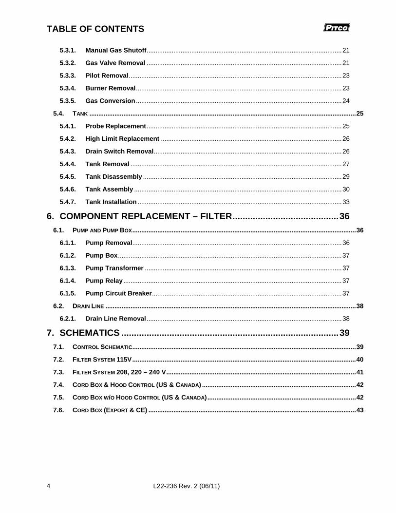
TABLE OF CONTENTS
4 L22-236 Rev. 2 (06/11)
5.3.1. Manual Gas Shutoff.............................................................................................................21
5.3.2. Gas Valve Removal .............................................................................................................21
5.3.3. Pilot Removal.......................................................................................................................23
5.3.4. Burner Removal...................................................................................................................23
5.3.5. Gas Conversion ...................................................................................................................24
5.4. TANK .....................................................................................................................................................25
5.4.1. Probe Replacement .............................................................................................................25
5.4.2. High Limit Replacement .....................................................................................................26
5.4.3. Drain Switch Removal.........................................................................................................26
5.4.4. Tank Removal ......................................................................................................................27
5.4.5. Tank Disassembly ...............................................................................................................29
5.4.6. Tank Assembly ....................................................................................................................30
5.4.7. Tank Installation ..................................................................................................................33
6. COMPONENT REPLACEMENT – FILTER..........................................36
6.1. PUMP AND PUMP BOX.............................................................................................................................36
6.1.1. Pump Removal.....................................................................................................................36
6.1.2. Pump Box.............................................................................................................................37
6.1.3. Pump Transformer ..............................................................................................................37
6.1.4. Pump Relay ..........................................................................................................................37
6.1.5. Pump Circuit Breaker..........................................................................................................37
6.2. DRAIN LINE ............................................................................................................................................38
6.2.1. Drain Line Removal .............................................................................................................38
7. SCHEMATICS ......................................................................................39
7.1. CONTROL SCHEMATIC.............................................................................................................................39
7.2. FILTER SYSTEM 115V.............................................................................................................................40
7.3. FILTER SYSTEM 208, 220 – 240 V..........................................................................................................41
7.4. CORD BOX & HOOD CONTROL (US & CANADA) ......................................................................................42
7.5. CORD BOX W/O HOOD CONTROL (US & CANADA)...................................................................................42
7.6. CORD BOX (EXPORT & CE) ....................................................................................................................43
MGII and MG2T GAS FRYER SERVICE
L22-236 Rev. 2 (06/11) 5
1. Theory of OperationKnowing and understanding the MGII sequence of fryer and component operation will enable you to diagnoseequipment failure more easily and accurately. (Note: The schematic references used are derived from theschematic on pages _ - _ of this manual.)
1.1. Heating SystemPower to the machine is turned ON: When the fryer is plugged in, power is supplied to the transformer, T1. The transformer steps the line
voltage down to 24VAC to operate the heat control circuit.
If Fuse, F1, on the Relay Board, A4, is good, the “AC POWER” LED illuminates. The computer is suppliedwith 24VAC and, if the drain valve handle is closed, the proximity switch, LS1, supplies 24 VAC to the DVI(drain valve interlock) Input at the Computer Controller, (reference connector J/P1, pin #5).
The Computer Controller, A1, is turned ON by pressing the button:
The Side On Relay, K3, will be energized, closing the circuit and the “S.O.” LED on the Relay Boardilluminates. If the High Limit, HL1, is NOT tripped the ignition module is supplied with 24VAC at terminal 6(24VAC).
The ignition module generates a 24VAC output from terminal 3(PV) to the PV terminal on the Gas Valve,V1, and generates a spark at the igniter, E2. When the pilot has lit and the ignition module has proven thepilot flame, it will have a 24VAC output at terminal 1(MV) resulting in 24VAC at connector J/P32, pin #2, onthe Relay Board. The Heat Demand Relay, K1, on the Relay Board will control the 24VAC supply to thegas valve when the controller calls for heat. Note: When the Computer Controller is on, the pilot shouldalways remain lit.
When the Computer Controller calls for heat:
The Heat Demand Relay is energized supplying the Gas Valve with 24VAC and the “HD” LED on theRelay Board illuminates. This also supplies the Computer Controller with a heat feedback signal, atconnector J/P32, pin #6.
1.2. High Limit System: If the High Limit, HL1, opens (“trips”), it interrupts the 24VAC supply to the ignition module. As a result, the
pilot goes out. When the Computer Controller calls for heat, it will not receive a 24VAC heat feedbacksignal. After 10 seconds, (90 seconds on first heat demand), of heat demand output lacking a heatfeedback signal, the Computer Controller will indicate “IGNITION FAILURE” or “HEAT FAIL”. After theHigh Limit is reset, (allow unit to cool below 400ºF, (204ºC), and press red reset button.), the ComputerController will have to be turned off and back on for the unit to heat.
1.3. Hood Relay System - U.S./Canada units only There is one Hood Relay, K6, per system, (“battery”) of fryers (located in a box mounted below the rear
bottom brace of left-hand fryer). It is wired in parallel to the Side On signal of every Computer Controller(both sides of an MG2T Split). When any side of any Computer Controller is turned on this relay isenergized, (providing power to the hood fan motor) and will stay energized until all Computer Controllersare turned off.
The Side On harness is equipped with a Fuse, F_. In the event of a short or over-current in the wiring tothe Hood Relay, all the F_ fuses in the system will blow. As a result, the fryer will no longer control thehood fan motor. To repair, first correct the over-current condition, and then replace all the F_ fuses in thefryer system.
1.4. Temperature Probe The Computer Controller receives temperature readings from the Temperature Probe, RT1.
The Temperature Probe resistance varies with temperature, decreasing as temperature rises.
SERVICE
6 L22-236 Rev. 2 (06/11)
1.5. Filter System
Opening the RED filter return valve handle closes the magnetically actuated Proximity Switch, LS4,causing the “Pump Run” Relay, K5, to be energized. This allows line voltage to flow to the Filter PumpMotor, M1. The Pump Motor begins to run. Closing the filter return valve handle will de-energize the relayand the Pump Motor will stop running.
The pump system is equipped with a Circuit Breaker, CB1, which de-energizes the system and the heattape, (if so equipped), in the event of over-current. The Circuit Breaker switch must be in the ON positionfor the pump and heat tape to operate.
The return piping system may be provided with optional Heat Tape, HTR1, to prevent solidification of solidshortening. The Heat Tape is low wattage and is on constantly to maintain liquid shortening in the line.
The Filter Pump Motor, M1, is equipped with a thermal overload. In the event of over-temperature of thepump motor, the thermal overload opens shutting off the pump. Once the pump motor has cooled, it canbe reset by pressing the red button at the end of the motor housing.

MGII and MG2T GAS FRYER SERVICE
L22-236 Rev. 2 (06/11) 7
2. Troubleshooting2.1. Fryer Troubleshooting
Problem Probable Causes Corrective ActionsNo power to appliance. Check main building power supply.Circuit Breaker tripped. Reset circuit breaker.
Power Cord loose or not connected.
Connect power cord. Check powercord where it enters the rear of thefryer’s entrance box. Verify that it isplugged all the way into thereceptacle.
Fuse, F1, blown.
Check Wire Reduction Board. If ACLamp is not lit check F1 fuse. If fuseis blown, replace with a 2.5 A fastacting fuse.
Transformer, T1, Defective. Check and replace if defective
Computer Controllerdisplay does not light.
Defective Controller
If AC Lamp on Wire ReductionBoard is lit, check for 24 VACbetween pins 1 and 2 on J/P 1. Ifvoltage is present and computerdisplay is not lit, controller isdefective. Check for shorts oncontroller outputs prior to replacingcontroller.
Computer is in Melt Cycle. Allow time for unit to heat up.
Main gas supply is off. Verify main gas supply is turned on.
Gas shut off valve (yellow handle) isclosed.
Verify gas shut-off valve is open,(yellow handle is in line with the gasline).
Gas valve is not turned on. Turn manual gas valve to “ON”.
Quick disconnect not properlyconnected.
Verify quick disconnect is properlyseated.
High temperature limit has tripped.Reset high temperature limit. Checkand replace if defective.
Ignition Module has locked out.
Turn Fryer off and back on again toreset ignition module. If lockoutrecurs, check for proper pilot flameand proper module operation.Replace if defective
Computer Controllershows “MELT” andheats slowly, or notat all.
Low gas pressure
Check regulated gas pressure atburner manifold. Verify pressurematches dataplate information.Adjust as necessary.
Main gas supply is off. Verify main gas supply is turned on.
Gas shut off valve (yellow handle) isclosed.
Verify gas shut-off valve is open,(yellow handle is in line with the gasline).
Gas valve is not turned on. Turn manual gas valve to “ON”.
Computer Controllershows “IGNITIONFAILURE” andalarms.
Quick disconnect not properlyconnected.
Verify quick disconnect is properlyseated.
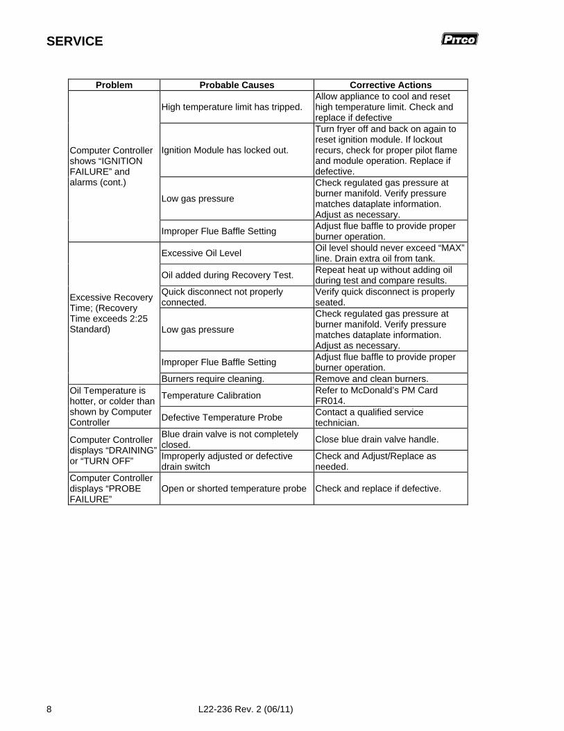
SERVICE
8 L22-236 Rev. 2 (06/11)
Problem Probable Causes Corrective Actions
High temperature limit has tripped.Allow appliance to cool and resethigh temperature limit. Check andreplace if defective
Ignition Module has locked out.
Turn fryer off and back on again toreset ignition module. If lockoutrecurs, check for proper pilot flameand module operation. Replace ifdefective.
Low gas pressure
Check regulated gas pressure atburner manifold. Verify pressurematches dataplate information.Adjust as necessary.
Computer Controllershows “IGNITIONFAILURE” andalarms (cont.)
Improper Flue Baffle SettingAdjust flue baffle to provide properburner operation.
Excessive Oil LevelOil level should never exceed “MAX”line. Drain extra oil from tank.
Oil added during Recovery Test.Repeat heat up without adding oilduring test and compare results.
Quick disconnect not properlyconnected.
Verify quick disconnect is properlyseated.
Low gas pressure
Check regulated gas pressure atburner manifold. Verify pressurematches dataplate information.Adjust as necessary.
Improper Flue Baffle SettingAdjust flue baffle to provide properburner operation.
Excessive RecoveryTime; (RecoveryTime exceeds 2:25Standard)
Burners require cleaning. Remove and clean burners.
Temperature CalibrationRefer to McDonald’s PM CardFR014.
Oil Temperature ishotter, or colder thanshown by ComputerController Defective Temperature Probe
Contact a qualified servicetechnician.
Blue drain valve is not completelyclosed.
Close blue drain valve handle.Computer Controllerdisplays “DRAINING”or “TURN OFF” Improperly adjusted or defective
drain switchCheck and Adjust/Replace asneeded.
Computer Controllerdisplays “PROBEFAILURE”
Open or shorted temperature probe Check and replace if defective.
MGII and MG2T GAS FRYER SERVICE
L22-236 Rev. 2 (06/11) 9
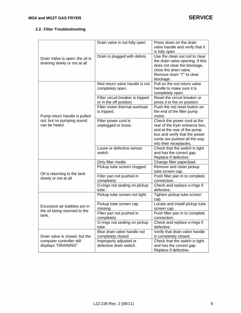
2.2. Filter Troubleshooting
Drain valve is not fully open Press down on the drainvalve handle and verify that itis fully open
Drain Valve is open; the oil isdraining slowly or not at all
Drain is plugged with debris. Use the clean out rod to clearthe drain valve opening. If thisdoes not clear the blockage,close the drain valve.Remove drain “T” to clearblockage.
Red return valve handle is notcompletely open.
Pull on the red return valvehandle to make sure it iscompletely open.
Filter circuit breaker is trippedor in the off position.
Reset the circuit breaker orpress it to the on position.
Filter motor thermal overloadis tripped.
Push the red reset button onthe end of the filter pumpmotor.
Filter power cord isunplugged or loose.
Check the power cord at therear of the fryer entrance box,and at the rear of the pumpbox and verify that the powercords are pushed all the wayinto their receptacles.
Pump return handle is pulledout, but no pumping soundcan be heard.
Loose or defective sensorswitch
Check that the switch is tightand has the correct gap.Replace if defective.
Dirty filter media Change filter paper/pad.Pickup tube screen clogged Remove and clean pickup
tube screen cap.Filter pan not pushed incompletely
Push filter pan in to completeconnection.
Oil is returning to the tankslowly or not at all.
O-rings not sealing on pickuptube.
Check and replace o-rings ifdefective.
Pickup tube screen not tight. Tighten pickup tube screencap.
Pickup tube screen capmissing
Locate and install pickup tubescreen cap.
Filter pan not pushed incompletely
Push filter pan in to completeconnection.
Excessive air bubbles are inthe oil being returned to thetank.
O-rings not sealing on pickuptube.
Check and replace o-rings ifdefective.
Blue drain valve handle notcompletely closed
Verify that drain valve handleis completely closed.Drain valve is closed, but the
computer controller stilldisplays “DRAINING”
Improperly adjusted ordefective drain switch.
Check that the switch is tightand has the correct gap.Replace if defective.
SERVICE
10 L22-236 Rev. 2 (06/11)
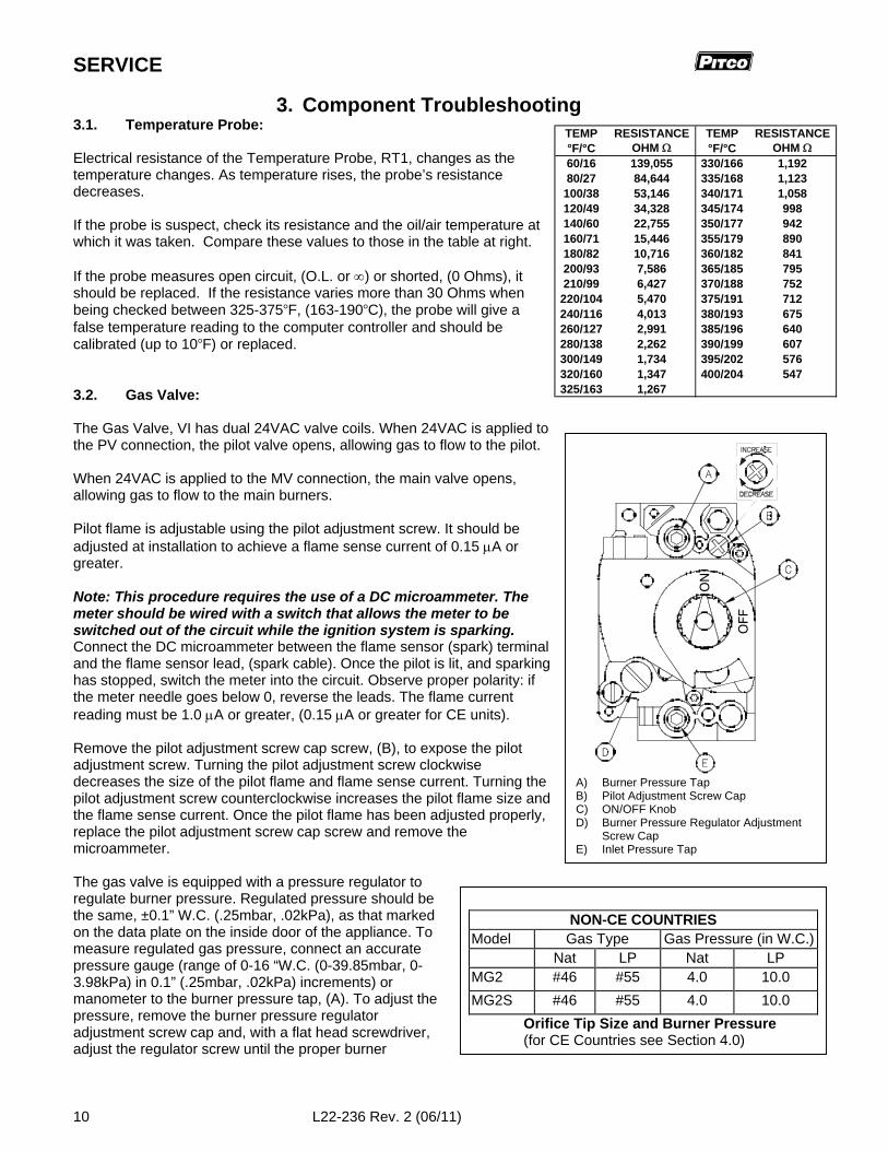
TEMP RESISTANCE TEMP RESISTANCE°F/°C OHM °F/°C OHM 60/16 139,055 330/166 1,19280/27 84,644 335/168 1,123
100/38 53,146 340/171 1,058120/49 34,328 345/174 998140/60 22,755 350/177 942160/71 15,446 355/179 890180/82 10,716 360/182 841200/93 7,586 365/185 795210/99 6,427 370/188 752220/104 5,470 375/191 712240/116 4,013 380/193 675260/127 2,991 385/196 640280/138 2,262 390/199 607300/149 1,734 395/202 576320/160 1,347 400/204 547325/163 1,267
OFF
ON
A) Burner Pressure TapB) Pilot Adjustment Screw CapC) ON/OFF KnobD) Burner Pressure Regulator Adjustment
Screw CapE) Inlet Pressure Tap
NON-CE COUNTRIESModel Gas Type Gas Pressure (in W.C.)
Nat LP Nat LPMG2 #46 #55 4.0 10.0
MG2S #46 #55 4.0 10.0
Orifice Tip Size and Burner Pressure(for CE Countries see Section 4.0)
3. Component Troubleshooting3.1. Temperature Probe:
Electrical resistance of the Temperature Probe, RT1, changes as thetemperature changes. As temperature rises, the probe’s resistancedecreases.
If the probe is suspect, check its resistance and the oil/air temperature atwhich it was taken. Compare these values to those in the table at right.
If the probe measures open circuit, (O.L. or ) or shorted, (0 Ohms), itshould be replaced. If the resistance varies more than 30 Ohms whenbeing checked between 325-375F, (163-190C), the probe will give afalse temperature reading to the computer controller and should becalibrated (up to 10F) or replaced.
3.2. Gas Valve:
The Gas Valve, VI has dual 24VAC valve coils. When 24VAC is applied tothe PV connection, the pilot valve opens, allowing gas to flow to the pilot.
When 24VAC is applied to the MV connection, the main valve opens,allowing gas to flow to the main burners.
Pilot flame is adjustable using the pilot adjustment screw. It should beadjusted at installation to achieve a flame sense current of 0.15 A orgreater.
Note: This procedure requires the use of a DC microammeter. Themeter should be wired with a switch that allows the meter to beswitched out of the circuit while the ignition system is sparking.Connect the DC microammeter between the flame sensor (spark) terminaland the flame sensor lead, (spark cable). Once the pilot is lit, and sparkinghas stopped, switch the meter into the circuit. Observe proper polarity: ifthe meter needle goes below 0, reverse the leads. The flame currentreading must be 1.0 A or greater, (0.15 A or greater for CE units).
Remove the pilot adjustment screw cap screw, (B), to expose the pilotadjustment screw. Turning the pilot adjustment screw clockwisedecreases the size of the pilot flame and flame sense current. Turning thepilot adjustment screw counterclockwise increases the pilot flame size andthe flame sense current. Once the pilot flame has been adjusted properly,replace the pilot adjustment screw cap screw and remove themicroammeter.
The gas valve is equipped with a pressure regulator toregulate burner pressure. Regulated pressure should bethe same, ±0.1” W.C. (.25mbar, .02kPa), as that markedon the data plate on the inside door of the appliance. Tomeasure regulated gas pressure, connect an accuratepressure gauge (range of 0-16 “W.C. (0-39.85mbar, 0-3.98kPa) in 0.1” (.25mbar, .02kPa) increments) ormanometer to the burner pressure tap, (A). To adjust thepressure, remove the burner pressure regulatoradjustment screw cap and, with a flat head screwdriver,adjust the regulator screw until the proper burner
MGII and MG2T GAS FRYER SERVICE
L22-236 Rev. 2 (06/11) 11
pressure is reached. Turning the screw clockwise will increase the burner pressure. Turning the screwcounterclockwise will decrease the burner pressure. When the pressure is correct, replace the regulatoradjustment screw cap.
3.3. High Limits:
The High Limit switch, HL1, is a normally closed switch that opens when the temperature at the high limitsensing bulb reaches 450F15F, (232C 8).
The high limit can be tested by utilizing the Computer Controller high limit test feature. Refer to McDonald’sPM Card FR015 for instructions on how to perform this test.
WARNING!This test should be performed by a qualified technician only! Monitor the fryer closely. This test willcause the oil to heat past the normal operating temperature and can cause damage to the machine andits operator if care is not taken.
WARNING!This test will cause the burners to run continuously.
If the switch does not open, (“trip”), between the prescribed limits it is defective and should be replaced. Oncetripped, the switch cannot be reset until the oil has cooled to approximately 400F, (204C). If the switchcannot be reset, (by pressing the red reset button), after the oil has cooled it is defective.
3.4. Drain Valve & Return Valve Switches:
These switches, LS1 and LS4, are magnetically actuated proximity switches.
When the Drain Valve Handle is moved to the open position, the Actuator magnet will move away from theswitch causing the Drain Valve Switch, LS1, to open. When the Drain Valve is closed the switch will close.
Opening the Red Return Valve Handle will close the proximity switch causing the “Pump Run” Relay, K5, to beenergized. The pump will begin to pump. Closing the return valve handle will open the proximity switchcausing the relay to de-energize and the pump will stop pumping. These switches can be checked with anOhmmeter. When the switch is closed, you should have continuity, (near 0 Ohms). The normal gap betweenthe Actuator magnet on the valve handle and the Sensor switch is 1/8” – ¼” (3 – 6mm).
3.5. Transformer:
The Transformer, T1, is a Class 2 step-down, multiple tap primary to 24VAC secondary device. Thetransformer can be checked by reading the input and output voltages. A quick check for transformer 24VACoutput can be done at the relay board behind the front panel. The AC LED is illuminated if the F1 fuse is goodand the board is receiving 24 VAC at connector J/P35 between pins #2 and #4.
3.6. Ignition Module:
The Ignition Module, A2, is a 24VAC input, single ignition trial, (with multiple retrials upon flame loss), device. Itsenses flame through the spark lead using flame rectification. When 24VAC is input between the 24V (THS onCE modules) terminal and 24V (GND), the ignition module generates a 24VAC output from its PV terminal.The igniter sparks until the module senses pilot flame, or for 85-90 seconds, at which time the module will lockout, whichever occurs first. When the module has proven the pilot flame, it will generate a 24VAC output at theMV terminal resulting in 24VAC at connector J/P32, pin #2 on the relay board. (The relay board then controlsthe 24VAC to the gas valve when the Computer Controller calls for heat.)
NOTE: A properly sized and installed gas line will deliver a minimum supply pressure of 7.0”W.C. (17.4mbars, 1.74kPa) natural gas or 13.0” W.C. (32.4mbars, 3.25kPa) propane to allappliances connected to the supply line, operating simultaneously at full demand. If regulatedgas pressure cannot be achieved with all appliances in the store running, there may be abuilding gas supply deficiency.
SERVICE
12 L22-236 Rev. 2 (06/11)
Note: When the Computer Controller is on, the pilot should always remain lit. If the pilot is not lit, either thehigh limit is open, or the ignition module has locked out. Ignition module lockout can be reset by turning thefryer off and back on again.
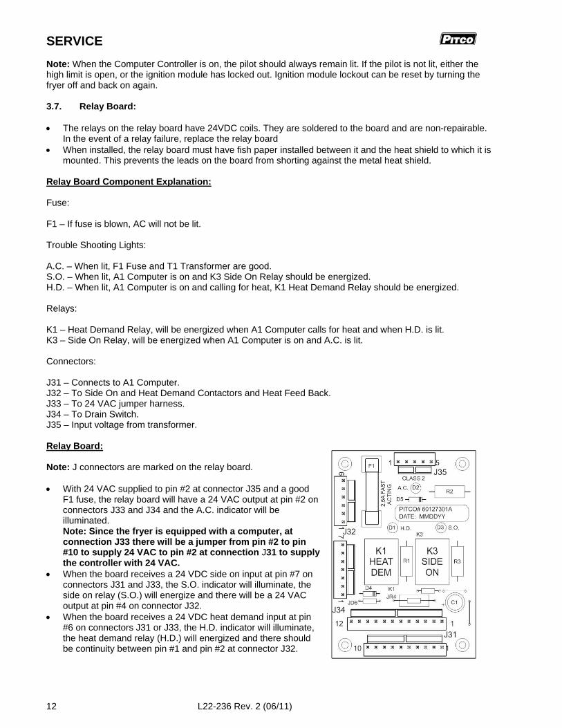
3.7. Relay Board:
The relays on the relay board have 24VDC coils. They are soldered to the board and are non-repairable.In the event of a relay failure, replace the relay board
When installed, the relay board must have fish paper installed between it and the heat shield to which it ismounted. This prevents the leads on the board from shorting against the metal heat shield.
Relay Board Component Explanation:
Fuse:
F1 – If fuse is blown, AC will not be lit.
Trouble Shooting Lights:
A.C. – When lit, F1 Fuse and T1 Transformer are good.S.O. – When lit, A1 Computer is on and K3 Side On Relay should be energized.H.D. – When lit, A1 Computer is on and calling for heat, K1 Heat Demand Relay should be energized.
Relays:
K1 – Heat Demand Relay, will be energized when A1 Computer calls for heat and when H.D. is lit.K3 – Side On Relay, will be energized when A1 Computer is on and A.C. is lit.
Connectors:
J31 – Connects to A1 Computer.J32 – To Side On and Heat Demand Contactors and Heat Feed Back.J33 – To 24 VAC jumper harness.J34 – To Drain Switch.J35 – Input voltage from transformer.
Relay Board:
Note: J connectors are marked on the relay board.
With 24 VAC supplied to pin #2 at connector J35 and a goodF1 fuse, the relay board will have a 24 VAC output at pin #2 onconnectors J33 and J34 and the A.C. indicator will beilluminated.Note: Since the fryer is equipped with a computer, atconnection J33 there will be a jumper from pin #2 to pin#10 to supply 24 VAC to pin #2 at connection J31 to supplythe controller with 24 VAC.
When the board receives a 24 VDC side on input at pin #7 onconnectors J31 and J33, the S.O. indicator will illuminate, theside on relay (S.O.) will energize and there will be a 24 VACoutput at pin #4 on connector J32.
When the board receives a 24 VDC heat demand input at pin#6 on connectors J31 or J33, the H.D. indicator will illuminate,the heat demand relay (H.D.) will energized and there shouldbe continuity between pin #1 and pin #2 at connector J32.
MGII and MG2T GAS FRYER SERVICE
L22-236 Rev. 2 (06/11) 13
3.8. Computer Controller:
The McDonald’s Computer controller is an electronic temperature control, timer and menu control. Inputsignals to the controller, (Power, DVI, Heat Feedback) are 24VAC. Controller outputs, (Side On, HeatDemand), are 24VDC. Temperature is measured via a thermistor temperature probe, RT1.
The same controller is used for McDonald’s Gas and Electric Fryers and for both Full and Split Tanks. Whenthe controller is powered up, it looks at probe and drain valve inputs to determine if it is a full or splitconfiguration. (For this reason, always connect the right harness first and then the left harness whenconnecting a Split, as power comes into the controller via the left harness.)
Note: When replacing a controller, it must be set up for the appliance type, (GAS, GAS2 or ELECTRIC) onwhich it is installed. The MGII fryer uses the GAS2 temperature algorithm. Failure to set the control up forthe correct appliance type may result in poor appliance operation.
Note: All controller test points are at connector P/J1 (closest connector to the controller).
With 24 VAC supplied to pin #1 (24 VAC supply) and pin #5 (24 VAC input from DVI), the display shouldread “OFF”.
With the controller turned on, there will be a 24 VDC output at pin #9 (side on).
When the controller calls for heat, there will be a 24 VDC output at pin #8 (heat demand) and a 24 VACinput at pin #6 (heat feed back). If the controller does not receive the 24VAC input at pin #6 within 10seconds, (90 seconds on first heat demand), the controller will display “HEAT FAIL” or “IGNITIONFAILURE”. This indicates that the controller did not receive a heat feedback signal when it called for heat.If this occurs:
Look to see if the pilot is lit. If not:
1. Check the high-limit switch, HL1. (Is it open (“tripped”)?)
2. Check the ignition module, A2, (Sensing pilot flame? locked out?).
If the pilot is lit:
3. Check the heat demand (HD) relay, K1, on the relay board; (Is heat demand relay energized?Continuity through COM and NO contacts?).
If display reads “PROBE”, check the resistance of the temperature probe, RT1. See the table on page 5.Check the wires and connectors between the probe and controller for continuity.
If display reads “SYSTEM” “FAILURE”, or “HOT HI-1”, test the temperature probe and the wires andconnectors between the probe and controller for a short.
If display reads “DRAINING” “TURN OFF”, this indicates that there is no 24VAC input at pin # 5, (DVIInput). Verify that the drain valve is closed, check the proximity switch on the drain valve, turn the fryer off,then turn the fryer on.
SERVICE
14 L22-236 Rev. 2 (06/11)
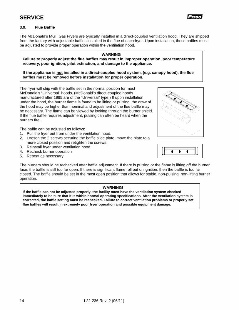
3.9. Flue Baffle
The McDonald’s MGII Gas Fryers are typically installed in a direct-coupled ventilation hood. They are shippedfrom the factory with adjustable baffles installed in the flue of each fryer. Upon installation, these baffles mustbe adjusted to provide proper operation within the ventilation hood.
The fryer will ship with the baffle set in the normal position for mostMcDonald’s “Universal” hoods. (McDonald’s direct-coupled hoodsmanufactured after 1995 are of the “Universal” type.) If upon installationunder the hood, the burner flame is found to be lifting or pulsing, the draw ofthe hood may be higher than nominal and adjustment of the flue baffle maybe necessary. The flame can be viewed by looking through the burner shield.If the flue baffle requires adjustment, pulsing can often be heard when theburners fire.
The baffle can be adjusted as follows:1. Pull the fryer out from under the ventilation hood.2. Loosen the 2 screws securing the baffle slide plate, move the plate to a
more closed position and retighten the screws.3. Reinstall fryer under ventilation hood.4. Recheck burner operation5. Repeat as necessary
The burners should be rechecked after baffle adjustment. If there is pulsing or the flame is lifting off the burnerface, the baffle is still too far open. If there is significant flame roll out on ignition, then the baffle is too farclosed. The baffle should be set in the most open position that allows for stable, non-pulsing, non-lifting burneroperation.
WARNINGFailure to properly adjust the flue baffles may result in improper operation, poor temperaturerecovery, poor ignition, pilot extinction, and damage to the appliance.
If the appliance is not installed in a direct-coupled hood system, (e.g. canopy hood), the fluebaffles must be removed before installation for proper operation.
WARNING!If the baffle can not be adjusted properly, the facility must have the ventilation system checkedimmediately to be sure that it is within normal operating specifications. After the ventilation system iscorrected, the baffle setting must be rechecked. Failure to correct ventilation problems or properly setflue baffles will result in extremely poor fryer operation and possible equipment damage.
MGII and MG2T GAS FRYER SERVICE
L22-236 Rev. 2 (06/11) 15
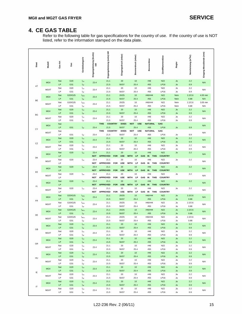
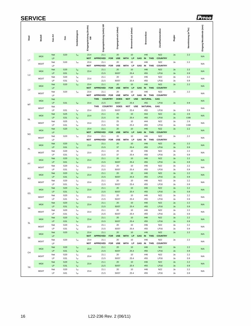
4. CE GAS TABLERefer to the following table for gas specifications for the country of use. If the country of use is NOTlisted, refer to the information stamped on the data plate.
Nat G20 I2H 21.1 20 10 #46 N22 Ja 2.2
LP G31 I3P 21.5 50/37 25.4 #55 LP16 Ja 0.9
Nat G20 I2H 21.1 20 10 #46 N22 Ja 2.2
LP G31 I3P 21.5 50/37 25.4 #55 LP16 Ja 0.9
Nat G20/G25 I2Esi 21.1 20/25 10 #46/#44 N22 Nein 2.2/2.6 4.00 mm
LP G31 I3P 21.5 50/37 25.4 #55 LP16 Nein 0.88 N/A
Nat G20/G25 I2Esi 21.1 20/25 10 #46/#44 N22 Nein 2.2/2.6 3.05 mm
LP G31 I3P 21.5 50/37 25.4 #55 LP16 Nein 0.88 N/A
Nat G20 I2H 21.1 20 10 #46 N22 Ja 2.2
LP G31 I3P 21.5 50/37 25.4 #55 LP16 Ja 0.9
Nat G20 I2H 21.1 20 10 #46 N22 Ja 2.2
LP G31 I3P 21.5 50/37 25.4 #55 LP16 Ja 0.9
Nat
LP G31 I3P 23.4 21.5 50/37 25.4 #55 LP16 Ja 0.9
Nat
LP G31 I3P 23.4 21.5 50/37 25.4 #55 LP16 Ja 0.9
Nat G20 I2H 21.1 20 10 #46 N22 Ja 2.2
LP G31 I3P 21.5 50/37 25.4 #55 LP16 Ja 0.9
Nat G20 I2H 21.1 20 10 #46 N22 Ja 2.2
LP G31 I3P 21.5 50/37 25.4 #55 LP16 Ja 0.9
Nat G20 I2H 23.4 21.1 20 10 #46 N22 Ja 2.2
LP
Nat G20 I2H 23.4 21.1 20 10 #46 N22 Ja 2.2
LP
Nat G20 I2H 23.4 21.1 20 10 #46 N22 Ja 2.2
LP
Nat G20 I2H 23.4 21.1 20 10 #46 N22 Ja 2.2
LP
Nat G20 I2H 23.4 21.1 20 10 #46 N22 Ja 2.2
LP
Nat G20 I2H 23.4 21.1 20 10 #46 N22 Ja 2.2
LP
Nat G20/G25 I2Esi 21.1 20/25 10 #46/#44 N22 Ja 2.2/2.6
LP G31 I3P 21.5 50/37 25.4 #55 LP16 Ja 0.88
Nat G20/G25 I2Esi 21.1 20/25 10 #46/#44 N22 Ja 2.2/2.6
LP G31 I3P 21.5 50/37 25.4 #55 LP16 Ja 0.88
Nat G20/G25 I2ELL 21.1 20/25 10 #46/#44 N22 Ja 2.2/2.6
LP G31 I3P 21.5 50/37 25.4 #55 LP16 Ja 0.88
Nat G20/G25 I2ELL 21.1 20/25 10 #46/#44 N22 Ja 2.2/2.6
LP G31 I3P 21.5 50/37 25.4 #55 LP16 Ja 0.88
Nat G20 I2H 21.1 20 10 #46 N22 Ja 2.2
LP G31 I3P 21.5 50/37 25.4 #55 LP16 Ja 0.9
Nat G20 I2H 21.1 20 10 #46 N22 Ja 2.2
LP G31 I3P 21.5 50/37 25.4 #55 LP16 Ja 0.9
Nat G20 I2H 21.1 20 10 #46 N22 Ja 2.2
LP G31 I3P 21.5 50/37 25.4 #55 LP16 Ja 0.9
Nat G20 I2H 21.1 20 10 #46 N22 Ja 2.2
LP G31 I3P 21.5 50/37 25.4 #55 LP16 Ja 0.9
Nat G20 I2H 21.1 20 10 #46 N22 Ja 2.2
LP G31 I3P 21.5 50/37 25.4 #55 LP16 Ja 0.9
Nat G20 I2H 21.1 20 10 #46 N22 Ja 2.2
LP G31 I3P 21.5 50/37 25.4 #55 LP16 Ja 0.9
Nat G20 I2H 21.1 20 10 #46 N22 Ja 2.2
LP G31 I3P 21.5 50/37 25.4 #55 LP16 Ja 0.9
Nat G20 I2H 21.1 20 10 #46 N22 Ja 2.2
LP G31 I3P 21.5 50/37 25.4 #55 LP16 Ja 0.9
Nat G20 I2H 21.1 20 10 #46 N22 Ja 2.2
LP G31 I3P 21.5 50/37 25.4 #55 LP16 Ja 0.9
Nat G20 I2H 21.1 20 10 #46 N22 Ja 2.2
LP G31 I3P 21.5 50/37 25.4 #55 LP16 Ja 0.9
Ga
s
Ge
räte
ka
teg
ori
e
Ein
ga
ng
sle
istu
ng
(b
rutt
o)
kW
En
ga
ng
sle
istu
ng
(n
ett
o)
kW
Re
gle
r
Ne
nn
leis
tun
g (
m3 /h
r)
Ein
ga
ng
sd
ruc
k (
mb
ar)
Bre
nn
erd
ruc
k (
mb
ar)
Bre
nn
erd
üs
e
Zü
nd
lfla
mm
en
dü
se
23.4
MGII 23.4
MGII
MGIIT
23.4
23.4
AT
BE
BG
MGIIT
23.4
FI
FR
DE
MGII
MGIIT
MGII
MGII
MGIIT
MGII
23.4
23.4
MGIIT
23.4
THIS COUNTRY DOES NOT USE NATURAL GAS
THIS COUNTRY DOES NOT USE NATURAL GAS
IT
GB
HU
IE
GR
MGII
MGIIT
23.4
MGII 23.4
MGIIT N/A
NOT APPROVED FOR USE WITH LP GAS IN THIS COUNTRY
MGIIT
NOT APPROVED FOR USE WITH LP GAS IN THIS COUNTRY
N/A
MGIIT 23.4 N/A
MGII 23.4
23.4 N/A
N/A
MGIIT 23.4 N/A
MGII 23.4
MGII 23.4
MGII
MGIIT
MGIIT 23.4
MGII 23.4
N/A
MGIIT
N/A
N/A
N/A
N/A
Ein
ga
ng
Me
ss
ble
nd
e (
mm
)
N/A
N/A
N/A
N/A
N/A
N/A
N/A
N/A
N/A
N/A
N/A
23.4
23.4
NOT APPROVED FOR USE WITH LP GAS IN THIS COUNTRY
NOT APPROVED FOR USE WITH LP GAS IN THIS COUNTRY
NOT APPROVED FOR USE WITH LP GAS IN THIS COUNTRY
NOT APPROVED FOR USE WITH LP GAS IN THIS COUNTRY
N/A
N/A
N/A
N/A
MGIIT
N/A
N/A
23.4
23.4
Mo
de
ll
Ga
s-A
rt
Sta
at
MGII
MGIIT
MGII
CY
CZ
DK
EE
SERVICE
16 L22-236 Rev. 2 (06/11)
Nat G20 I2H 23.4 21.1 20 10 #46 N22 Ja 2.2
LP
Nat G20 I2H 23.4 21.1 20 10 #46 N22 Ja 2.2
LP
Nat G20 I2E 21.1 20 10 #46 N22 Ja 2.2
LP G31 I3P 21.5 50/37 25.4 #55 LP16 Ja 0.9
Nat G20 I2E 21.1 20 10 #46 N22 Ja 2.2
LP G31 I3P 21.5 50/37 25.4 #55 LP16 Ja 0.9
Nat G20 I2H 23.4 21.1 20 10 #46 N22 Ja 2.2
LP
Nat G20 I2H 23.4 21.1 20 10 #46 N22 Ja 2.2
LP
Nat
LP G31 I3P 23.4 21.5 50/37 25.4 #55 LP16 Ja 0.9
Nat
LP G31 I3P 23.4 21.5 50/37 25.4 #55 LP16 Ja 0.9
Nat G25 I2L 21.1 25 10 #44 N22 Ja 2.6
LP G31 I3P 21.5 50 25.4 #55 LP16 Ja 0.88
Nat G25 I2L 21.1 25 10 #44 N22 Ja 2.6
LP G31 I3P 21.5 50 25.4 #55 LP16 Ja 0.88
Nat G20 I2H 23.4 21.1 20 10 #46 N22 Ja 2.2
LP
Nat G20 I2H 23.4 21.1 20 10 #46 N22 Ja 2.2
LP
Nat G20 I2E 21.1 20 10 #46 N22 Ja 2.2
LP G31 I3P 21.5 37 25.4 #55 LP16 Ja 0.9
Nat G20 I2E 21.1 20 10 #46 N22 Ja 2.2
LP G31 I3P 21.5 37 25.4 #55 LP16 Ja 0.9
Nat G20 I2H 21.1 20 10 #46 N22 Ja 2.2
LP G31 I3P 21.5 50/37 25.4 #55 LP16 Ja 0.9
Nat G20 I2H 21.1 20 10 #46 N22 Ja 2.2
LP G31 I3P 21.5 50/37 25.4 #55 LP16 Ja 0.9
Nat G20 I2H 21.1 20 10 #46 N22 Ja 2.2
LP G31 I3P 21.5 50/37 25.4 #55 LP16 Ja 0.9
Nat G20 I2H 21.1 20 10 #46 N22 Ja 2.2
LP G31 I3P 21.5 50/37 25.4 #55 LP16 Ja 0.9
Nat G20 I2H 21.1 20 10 #46 N22 Ja 2.2
LP G31 I3P 21.5 50/37 25.4 #55 LP16 Ja 0.9
Nat G20 I2H 21.1 20 10 #46 N22 Ja 2.2
LP G31 I3P 21.5 50/37 25.4 #55 LP16 Ja 0.9
Nat G20 I2H 21.1 20 10 #46 N22 Ja 2.2
LP G31 I3P 21.5 50/37 25.4 #55 LP16 Ja 0.9
Nat G20 I2H 21.1 20 10 #46 N22 Ja 2.2
LP G31 I3P 21.5 50/37 25.4 #55 LP16 Ja 0.9
Nat G20 I2H 21.1 20 10 #46 N22 Ja 2.2
LP G31 I3P 21.5 50/37 25.4 #55 LP16 Ja 0.9
Nat G20 I2H 21.1 20 10 #46 N22 Ja 2.2
LP G31 I3P 21.5 50/37 25.4 #55 LP16 Ja 0.9
Nat G20 I2H 23.4 21.1 20 10 #46 N22 Ja 2.2
LP
Nat G20 I2H 23.4 21.1 20 10 #46 N22 Ja 2.2
LP
Nat G20 I2H 21.1 20 10 #46 N22 Ja 2.2
LP G31 I3P 21.5 50/37 25.4 #55 LP16 Ja 0.9
Nat G20 I2H 21.1 20 10 #46 N22 Ja 2.2
LP G31 I3P 21.5 50/37 25.4 #55 LP16 Ja 0.9
Nat G20 I2H 21.1 20 10 #46 N22 Ja 2.2
LP G31 I3P 21.5 50/37 25.4 #55 LP16 Ja 0.9
Nat G20 I2H 21.1 20 10 #46 N22 Ja 2.2
LP G31 I3P 21.5 50/37 25.4 #55 LP16 Ja 0.9
LT
LU
LV
MT
NL
MGII
MGIIT
N/A
N/AMGII 23.4
MGII
MGIIT
MGIIT 23.4
NOT APPROVED FOR USE WITH LP GAS IN THIS COUNTRY
N/AMGII 23.4
MGII
MGIIT
THIS COUNTRY DOES NOT USE NATURAL GAS
MGIIT 23.4 N/A
MGIIT
N/A
N/A
NOT APPROVED FOR USE WITH LP GAS IN THIS COUNTRY
NOT APPROVED FOR USE WITH LP GAS IN THIS COUNTRY
MGII
CH
PL
PT
RO
ES
N/A
TR
MGII 23.4
MGII 23.4
MGII 23.4
SK
SL
N/A
MGIIT 23.4 N/A
23.4 N/A
N/A
MGIIT 23.4 N/A
23.4 N/A
N/AMGII 23.4
23.4 N/A
N/AMGII 23.4
N/A
N/AMGII 23.4
23.4
N/A
N/AMGII 23.4
N/A
N/A
N/A
N/A
N/A
N/A
N/A
N/A
N/A
N/A
NOT APPROVED FOR USE WITH LP GAS IN THIS COUNTRY
NOT APPROVED FOR USE WITH LP GAS IN THIS COUNTRY
NOT APPROVED FOR USE WITH LP GAS IN THIS COUNTRY
THIS COUNTRY DOES NOT USE NATURAL GAS
NOT APPROVED FOR USE WITH LP GAS IN THIS COUNTRY
NOT APPROVED FOR USE WITH LP GAS IN THIS COUNTRY
MGIIT 23.4
MGIIT 23.4
MGII 23.4
MGII
MGIIT
MGIIT
MGIIT
MGIIT
MGIIT
SE
NO
Bre
nn
erd
üse
Zü
nd
lfla
mm
end
üse
Reg
ler
Nen
nle
istu
ng
(m
3 /hr)
Ein
gan
g M
essb
len
de
(mm
)
Sta
at
Mo
del
l
Gas
-Art
Gas
Ger
ätek
ateg
ori
e
Ein
gan
gsl
eist
un
g (
bru
tto
) kW
En
gan
gsl
eist
un
g (
net
to)
kW
Ein
gan
gsd
ruck
(m
bar
)
Bre
nn
erd
ruck
(m
bar
)
MGII and MG2T GAS FRYER SERVICE
L22-236 Rev. 2 (06/11) 17
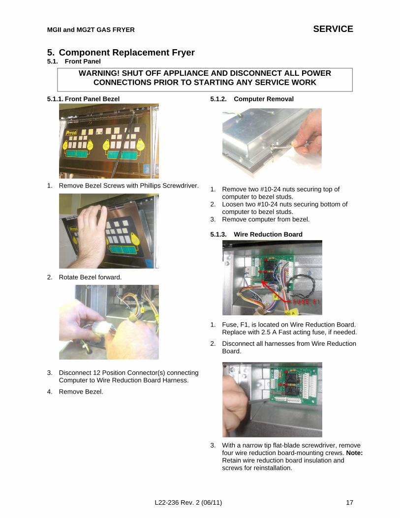
5. Component Replacement Fryer5.1. Front Panel
5.1.1. Front Panel Bezel
1. Remove Bezel Screws with Phillips Screwdriver.
2. Rotate Bezel forward.
3. Disconnect 12 Position Connector(s) connectingComputer to Wire Reduction Board Harness.
4. Remove Bezel.
5.1.2. Computer Removal
1. Remove two #10-24 nuts securing top ofcomputer to bezel studs.
2. Loosen two #10-24 nuts securing bottom ofcomputer to bezel studs.
3. Remove computer from bezel.
5.1.3. Wire Reduction Board
1. Fuse, F1, is located on Wire Reduction Board.Replace with 2.5 A Fast acting fuse, if needed.
2. Disconnect all harnesses from Wire ReductionBoard.
3. With a narrow tip flat-blade screwdriver, removefour wire reduction board-mounting crews. Note:Retain wire reduction board insulation andscrews for reinstallation.
WARNING! SHUT OFF APPLIANCE AND DISCONNECT ALL POWERCONNECTIONS PRIOR TO STARTING ANY SERVICE WORK
SERVICE
18 L22-236 Rev. 2 (06/11)
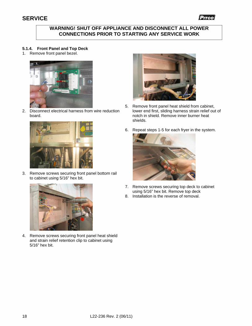
5.1.4. Front Panel and Top Deck1. Remove front panel bezel.
2. Disconnect electrical harness from wire reductionboard.
3. Remove screws securing front panel bottom railto cabinet using 5/16” hex bit.
4. Remove screws securing front panel heat shieldand strain relief retention clip to cabinet using5/16” hex bit.
5. Remove front panel heat shield from cabinet,lower end first, sliding harness strain relief out ofnotch in shield. Remove inner burner heatshields.
6. Repeat steps 1-5 for each fryer in the system.
7. Remove screws securing top deck to cabinetusing 5/16” hex bit. Remove top deck
8. Installation is the reverse of removal.
WARNING! SHUT OFF APPLIANCE AND DISCONNECT ALL POWERCONNECTIONS PRIOR TO STARTING ANY SERVICE WORK
MGII and MG2T GAS FRYER SERVICE
L22-236 Rev. 2 (06/11) 19
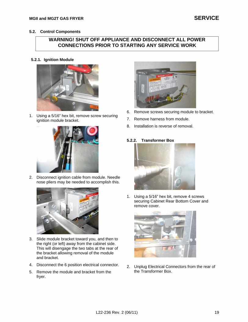
5.2. Control Components
5.2.1. Ignition Module
1. Using a 5/16” hex bit, remove screw securingignition module bracket.
2. Disconnect ignition cable from module. Needlenose pliers may be needed to accomplish this.
3. Slide module bracket toward you, and then tothe right (or left) away from the cabinet side.This will disengage the two tabs at the rear ofthe bracket allowing removal of the moduleand bracket.
4. Disconnect the 6 position electrical connector.
5. Remove the module and bracket from thefryer.
6. Remove screws securing module to bracket.
7. Remove harness from module.
8. Installation is reverse of removal.
5.2.2. Transformer Box
1. Using a 5/16” hex bit, remove 4 screwssecuring Cabinet Rear Bottom Cover andremove cover.
2. Unplug Electrical Connectors from the rear ofthe Transformer Box.
WARNING! SHUT OFF APPLIANCE AND DISCONNECT ALL POWERCONNECTIONS PRIOR TO STARTING ANY SERVICE WORK
SERVICE
20 L22-236 Rev. 2 (06/11)
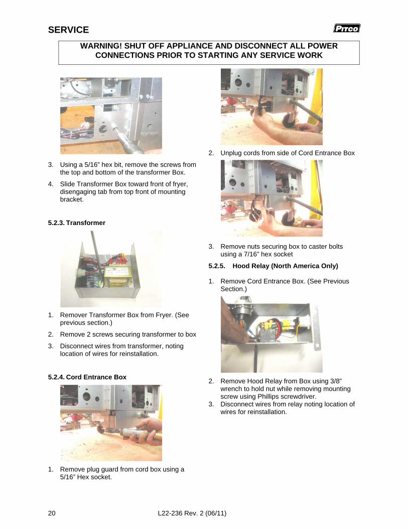
3. Using a 5/16” hex bit, remove the screws fromthe top and bottom of the transformer Box.
4. Slide Transformer Box toward front of fryer,disengaging tab from top front of mountingbracket.
5.2.3. Transformer
1. Remover Transformer Box from Fryer. (Seeprevious section.)
2. Remove 2 screws securing transformer to box
3. Disconnect wires from transformer, notinglocation of wires for reinstallation.
5.2.4. Cord Entrance Box
1. Remove plug guard from cord box using a5/16” Hex socket.
2. Unplug cords from side of Cord Entrance Box
3. Remove nuts securing box to caster boltsusing a 7/16” hex socket
5.2.5. Hood Relay (North America Only)
1. Remove Cord Entrance Box. (See PreviousSection.)
2. Remove Hood Relay from Box using 3/8”wrench to hold nut while removing mountingscrew using Phillips screwdriver.
3. Disconnect wires from relay noting location ofwires for reinstallation.
WARNING! SHUT OFF APPLIANCE AND DISCONNECT ALL POWERCONNECTIONS PRIOR TO STARTING ANY SERVICE WORK
MGII and MG2T GAS FRYER SERVICE
L22-236 Rev. 2 (06/11) 21
5.3. Gas Train
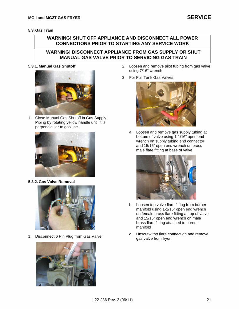
5.3.1. Manual Gas Shutoff
1. Close Manual Gas Shutoff in Gas SupplyPiping by rotating yellow handle until it isperpendicular to gas line.
5.3.2. Gas Valve Removal
1. Disconnect 6 Pin Plug from Gas Valve
2. Loosen and remove pilot tubing from gas valveusing 7/16” wrench
3. For Full Tank Gas Valves:
a. Loosen and remove gas supply tubing atbottom of valve using 1-1/16” open endwrench on supply tubing end connectorand 15/16” open end wrench on brassmale flare fitting at base of valve
b. Loosen top valve flare fitting from burnermanifold using 1-1/16” open end wrenchon female brass flare fitting at top of valveand 15/16” open end wrench on malebrass flare fitting attached to burnermanifold
c. Unscrew top flare connection and removegas valve from fryer.
WARNING! SHUT OFF APPLIANCE AND DISCONNECT ALL POWERCONNECTIONS PRIOR TO STARTING ANY SERVICE WORK
WARNING! DISCONNECT APPLIANCE FROM GAS SUPPLY OR SHUTMANUAL GAS VALVE PRIOR TO SERVICING GAS TRAIN

SERVICE
22 L22-236 Rev. 2 (06/11)
4. For Split Tank Gas Valves:
a. Loosen and disconnect top valve flarefitting from burner manifold using 1-1/16”open end wrench on female brass flarefitting at top of valve and15/16” open endwrench on male brass flare fitting attachedto burner manifold
b. Move valve forward to access supplytubing at bottom of valve.
c. Loosen and remove gas supply tubing atbottom of valve using 1-1/16” open-endwrench on tubing end connector, andremove valve from fryer.
5. Remove brass quick disconnect fittings fromGas Valve using 15/16” open end wrench onmale flare fitting at bottom of valve, and 7/8”thin open end wrench on male end of femalefitting at top of valve.
6. For Full Tank valves, remove screw securingheat shield to valve using 1/4” socket.
7. Straighten and remove vent tubing.
8. Installation is reverse of removal. Be sure tore-install heat shield on valve.
9. Leak test all gas fittings after re-assemblyusing an appropriate leak detection fluid.
WARNING! SHUT OFF APPLIANCE AND DISCONNECT ALL POWERCONNECTIONS PRIOR TO STARTING ANY SERVICE WORK
WARNING! DISCONNECT APPLIANCE FROM GAS SUPPLY OR SHUTMANUAL GAS VALVE PRIOR TO SERVICING GAS TRAIN
MGII and MG2T GAS FRYER SERVICE
L22-236 Rev. 2 (06/11) 23
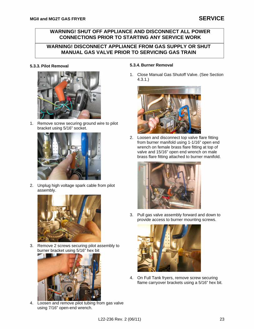
5.3.3. Pilot Removal
1. Remove screw securing ground wire to pilotbracket using 5/16” socket.
2. Unplug high voltage spark cable from pilotassembly.
3. Remove 2 screws securing pilot assembly toburner bracket using 5/16” hex bit
4. Loosen and remove pilot tubing from gas valveusing 7/16” open-end wrench.
5.3.4. Burner Removal
1. Close Manual Gas Shutoff Valve. (See Section4.3.1.)
2. Loosen and disconnect top valve flare fittingfrom burner manifold using 1-1/16” open endwrench on female brass flare fitting at top ofvalve and 15/16” open end wrench on malebrass flare fitting attached to burner manifold.
3. Pull gas valve assembly forward and down toprovide access to burner mounting screws.
4. On Full Tank fryers, remove screw securingflame carryover brackets using a 5/16” hex bit.
WARNING! SHUT OFF APPLIANCE AND DISCONNECT ALL POWERCONNECTIONS PRIOR TO STARTING ANY SERVICE WORK
WARNING! DISCONNECT APPLIANCE FROM GAS SUPPLY OR SHUTMANUAL GAS VALVE PRIOR TO SERVICING GAS TRAIN
SERVICE
24 L22-236 Rev. 2 (06/11)
5. Remove burner mounting screws, (2/burner)using 5/16 hex bit.
6. Remove burners.
7. Note: On split vat fryers it may be necessary tobend up the outside tabs on the burner bracketshield to allow removal of the outside burners.
8. Installation is reverse of removal. Be sure thatburner is properly seated on orifice spudswhen re-installing burner.
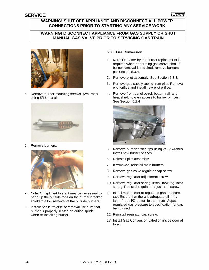
5.3.5. Gas Conversion
1. Note: On some fryers, burner replacement isrequired when performing gas conversion. Ifburner removal is required, remove burnersper Section 5.3.4.
2. Remove pilot assembly. See Section 5.3.3.
3. Remove gas supply tubing from pilot. Removepilot orifice and install new pilot orifice.
4. Remove front panel bezel, bottom rail, andheat shield to gain access to burner orifices.See Section 5.1.4
5. Remove burner orifice tips using 7/16” wrench.Install new burner orifices
6. Reinstall pilot assembly.
7. If removed, reinstall main burners.
8. Remove gas valve regulator cap screw.
9. Remove regulator adjustment screw.
10. Remove regulator spring. Install new regulatorspring. Reinstall regulator adjustment screw
11. Install manometer at regulated gas pressuretap. Ensure that there is adequate oil in frytank. Press I/O button to start fryer. Adjustregulated gas pressure to specification for gasbeing used.
12. Reinstall regulator cap screw.
13. Install Gas Conversion Label on inside door offryer.
WARNING! SHUT OFF APPLIANCE AND DISCONNECT ALL POWERCONNECTIONS PRIOR TO STARTING ANY SERVICE WORK
WARNING! DISCONNECT APPLIANCE FROM GAS SUPPLY OR SHUTMANUAL GAS VALVE PRIOR TO SERVICING GAS TRAIN
MGII and MG2T GAS FRYER SERVICE
L22-236 Rev. 2 (06/11) 25
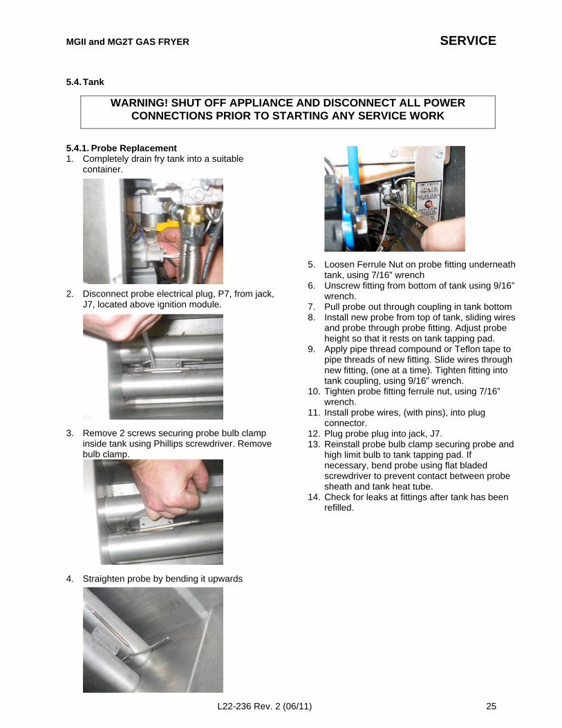
5.4. Tank
5.4.1. Probe Replacement1. Completely drain fry tank into a suitable
container.
2. Disconnect probe electrical plug, P7, from jack,J7, located above ignition module.
3. Remove 2 screws securing probe bulb clampinside tank using Phillips screwdriver. Removebulb clamp.
4. Straighten probe by bending it upwards
5. Loosen Ferrule Nut on probe fitting underneathtank, using 7/16” wrench
6. Unscrew fitting from bottom of tank using 9/16”wrench.
7. Pull probe out through coupling in tank bottom8. Install new probe from top of tank, sliding wires
and probe through probe fitting. Adjust probeheight so that it rests on tank tapping pad.
9. Apply pipe thread compound or Teflon tape topipe threads of new fitting. Slide wires throughnew fitting, (one at a time). Tighten fitting intotank coupling, using 9/16” wrench.
10. Tighten probe fitting ferrule nut, using 7/16”wrench.
11. Install probe wires, (with pins), into plugconnector.
12. Plug probe plug into jack, J7.13. Reinstall probe bulb clamp securing probe and
high limit bulb to tank tapping pad. Ifnecessary, bend probe using flat bladedscrewdriver to prevent contact between probesheath and tank heat tube.
14. Check for leaks at fittings after tank has beenrefilled.
WARNING! SHUT OFF APPLIANCE AND DISCONNECT ALL POWERCONNECTIONS PRIOR TO STARTING ANY SERVICE WORK
SERVICE
26 L22-236 Rev. 2 (06/11)
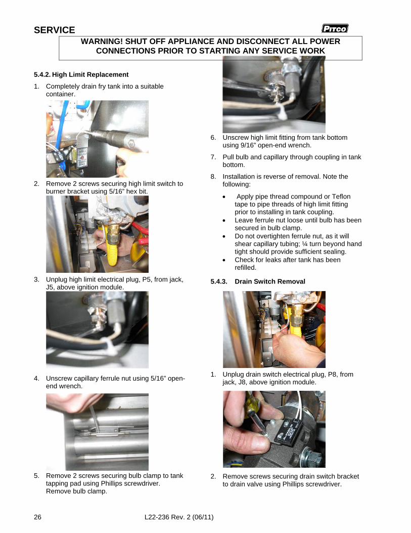
5.4.2. High Limit Replacement
1. Completely drain fry tank into a suitablecontainer.
2. Remove 2 screws securing high limit switch toburner bracket using 5/16” hex bit.
3. Unplug high limit electrical plug, P5, from jack,J5, above ignition module.
4. Unscrew capillary ferrule nut using 5/16” open-end wrench.
5. Remove 2 screws securing bulb clamp to tanktapping pad using Phillips screwdriver.Remove bulb clamp.
6. Unscrew high limit fitting from tank bottomusing 9/16” open-end wrench.
7. Pull bulb and capillary through coupling in tankbottom.
8. Installation is reverse of removal. Note thefollowing:
Apply pipe thread compound or Teflontape to pipe threads of high limit fittingprior to installing in tank coupling.
Leave ferrule nut loose until bulb has beensecured in bulb clamp.
Do not overtighten ferrule nut, as it willshear capillary tubing; ¼ turn beyond handtight should provide sufficient sealing.
Check for leaks after tank has beenrefilled.
5.4.3. Drain Switch Removal
1. Unplug drain switch electrical plug, P8, fromjack, J8, above ignition module.
2. Remove screws securing drain switch bracketto drain valve using Phillips screwdriver.
WARNING! SHUT OFF APPLIANCE AND DISCONNECT ALL POWERCONNECTIONS PRIOR TO STARTING ANY SERVICE WORK
MGII and MG2T GAS FRYER SERVICE
L22-236 Rev. 2 (06/11) 27
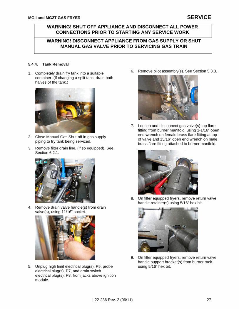
5.4.4. Tank Removal
1. Completely drain fry tank into a suitablecontainer. (If changing a split tank, drain bothhalves of the tank.)
2. Close Manual Gas Shut-off in gas supplypiping to fry tank being serviced.
3. Remove filter drain line, (if so equipped). SeeSection 6.2.1.
4. Remove drain valve handle(s) from drainvalve(s), using 11/16” socket.
5. Unplug high limit electrical plug(s), P5, probeelectrical plug(s), P7, and drain switchelectrical plug(s), P8, from jacks above ignitionmodule.
6. Remove pilot assembly(s). See Section 5.3.3.
7. Loosen and disconnect gas valve(s) top flarefitting from burner manifold, using 1-1/16” openend wrench on female brass flare fitting at topof valve and 15/16” open end wrench on malebrass flare fitting attached to burner manifold.
8. On filter equipped fryers, remove return valvehandle retainer(s) using 5/16” hex bit.
9. On filter equipped fryers, remove return valvehandle support bracket(s) from burner rackusing 5/16” hex bit.
WARNING! SHUT OFF APPLIANCE AND DISCONNECT ALL POWERCONNECTIONS PRIOR TO STARTING ANY SERVICE WORK
WARNING! DISCONNECT APPLIANCE FROM GAS SUPPLY OR SHUTMANUAL GAS VALVE PRIOR TO SERVICING GAS TRAIN
SERVICE
28 L22-236 Rev. 2 (06/11)
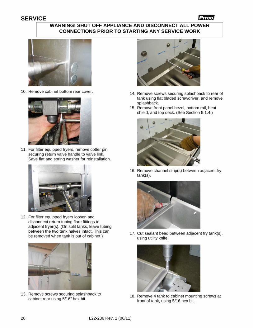
10. Remove cabinet bottom rear cover.
11. For filter equipped fryers, remove cotter pinsecuring return valve handle to valve link.Save flat and spring washer for reinstallation.
12. For filter equipped fryers loosen anddisconnect return tubing flare fittings toadjacent fryer(s). (On split tanks, leave tubingbetween the two tank halves intact. This canbe removed when tank is out of cabinet.)
13. Remove screws securing splashback tocabinet rear using 5/16” hex bit.
14. Remove screws securing splashback to rear oftank using flat bladed screwdriver, and removesplashback.
15. Remove front panel bezel, bottom rail, heatshield, and top deck. (See Section 5.1.4.)
16. Remove channel strip(s) between adjacent frytank(s).
17. Cut sealant bead between adjacent fry tank(s),using utility knife.
18. Remove 4 tank to cabinet mounting screws atfront of tank, using 5/16 hex bit.
WARNING! SHUT OFF APPLIANCE AND DISCONNECT ALL POWERCONNECTIONS PRIOR TO STARTING ANY SERVICE WORK
MGII and MG2T GAS FRYER SERVICE
L22-236 Rev. 2 (06/11) 29
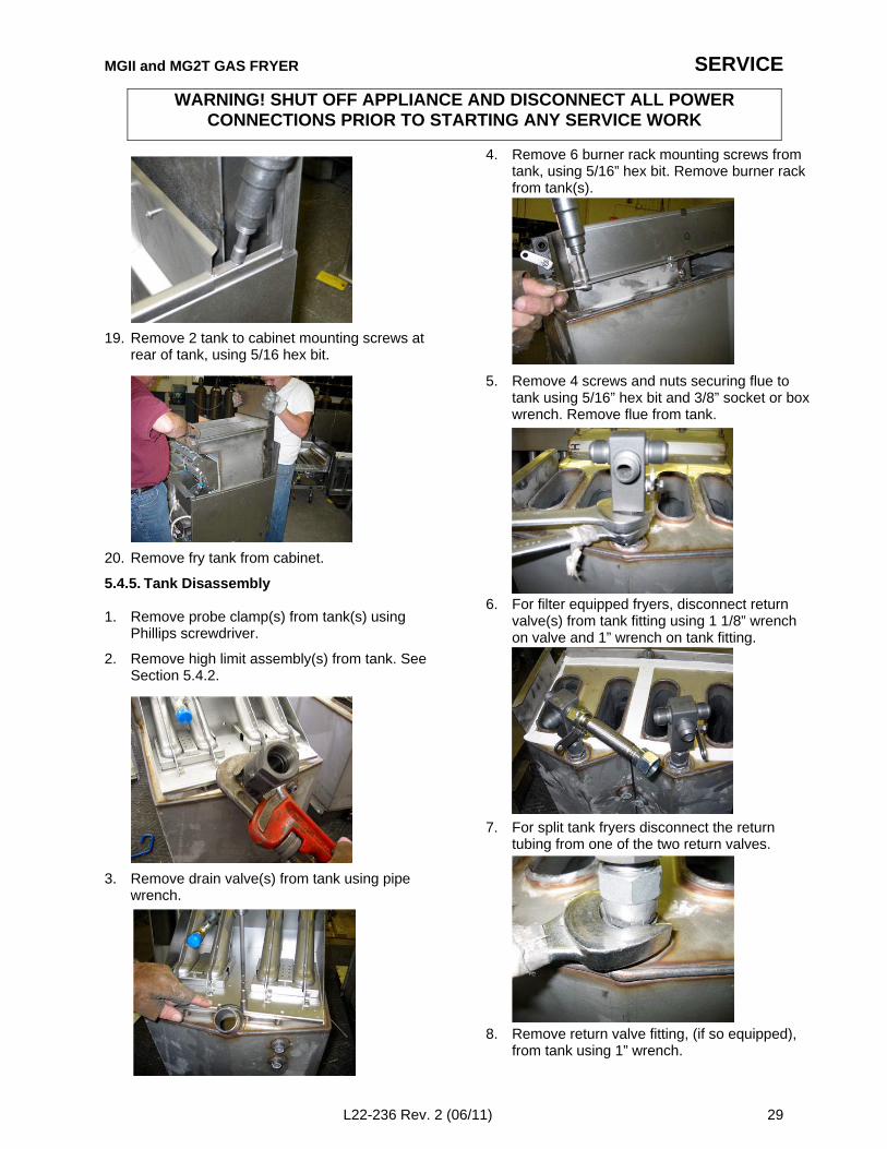
19. Remove 2 tank to cabinet mounting screws atrear of tank, using 5/16 hex bit.
20. Remove fry tank from cabinet.
5.4.5. Tank Disassembly
1. Remove probe clamp(s) from tank(s) usingPhillips screwdriver.
2. Remove high limit assembly(s) from tank. SeeSection 5.4.2.
3. Remove drain valve(s) from tank using pipewrench.
4. Remove 6 burner rack mounting screws fromtank, using 5/16” hex bit. Remove burner rackfrom tank(s).
5. Remove 4 screws and nuts securing flue totank using 5/16” hex bit and 3/8” socket or boxwrench. Remove flue from tank.
6. For filter equipped fryers, disconnect returnvalve(s) from tank fitting using 1 1/8” wrenchon valve and 1” wrench on tank fitting.
7. For split tank fryers disconnect the returntubing from one of the two return valves.
8. Remove return valve fitting, (if so equipped),from tank using 1” wrench.
WARNING! SHUT OFF APPLIANCE AND DISCONNECT ALL POWERCONNECTIONS PRIOR TO STARTING ANY SERVICE WORK
SERVICE
30 L22-236 Rev. 2 (06/11)
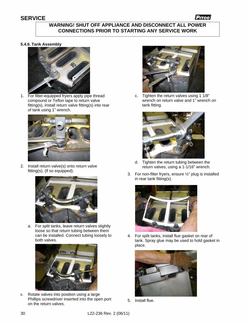
5.4.6. Tank Assembly
1. For filter-equipped fryers apply pipe threadcompound or Teflon tape to return valvefitting(s), Install return valve fitting(s) into rearof tank using 1” wrench.
2. Install return valve(s) onto return valvefitting(s), (if so equipped).
a. For split tanks, leave return valves slightlyloose so that return tubing between themcan be installed. Connect tubing loosely toboth valves.
b. Rotate valves into position using a largePhillips screwdriver inserted into the open porton the return valves.
c. Tighten the return valves using 1 1/8”wrench on return valve and 1” wrench ontank fitting.
d. Tighten the return tubing between thereturn valves, using a 1-1/16” wrench.
3. For non-filter fryers, ensure ½” plug is installedin rear tank fitting(s).
4. For split tanks, install flue gasket on rear oftank. Spray glue may be used to hold gasket inplace.
5. Install flue.
WARNING! SHUT OFF APPLIANCE AND DISCONNECT ALL POWERCONNECTIONS PRIOR TO STARTING ANY SERVICE WORK
MGII and MG2T GAS FRYER SERVICE
L22-236 Rev. 2 (06/11) 31
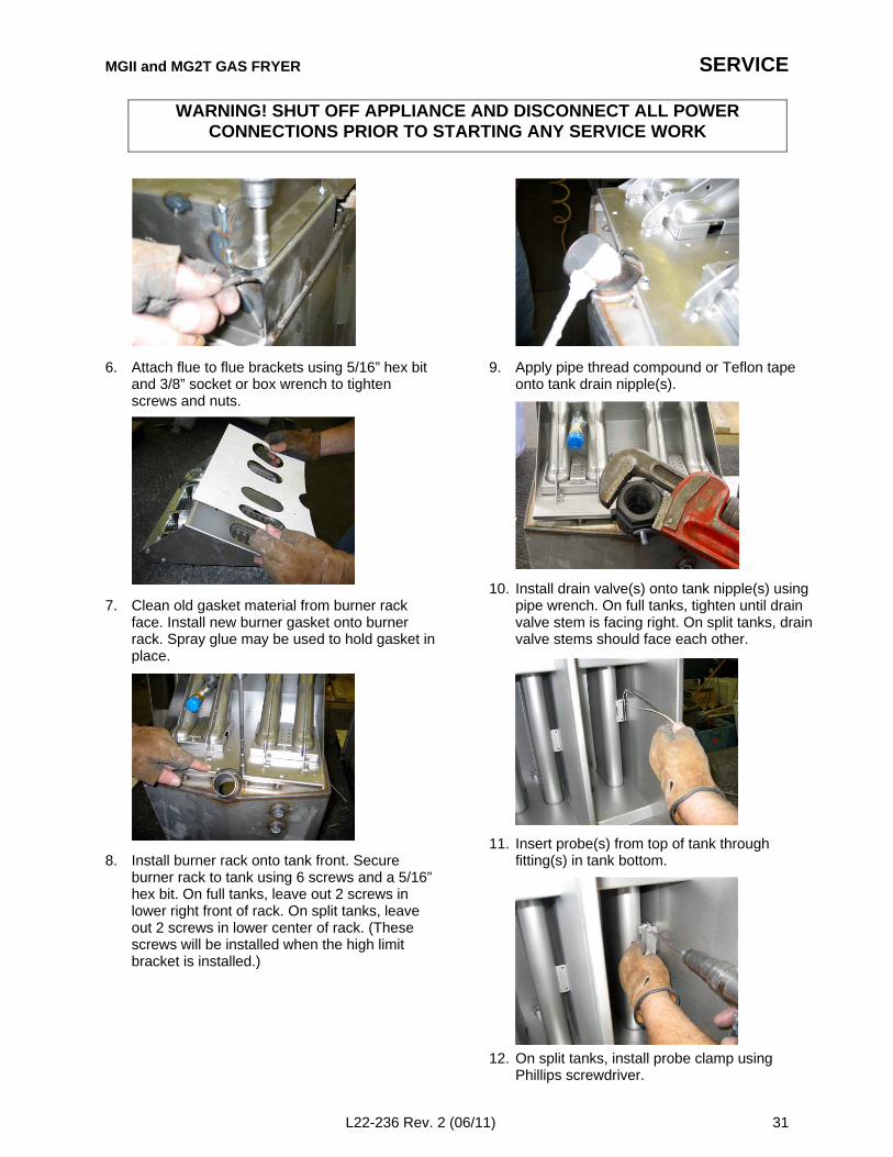
6. Attach flue to flue brackets using 5/16” hex bitand 3/8” socket or box wrench to tightenscrews and nuts.
7. Clean old gasket material from burner rackface. Install new burner gasket onto burnerrack. Spray glue may be used to hold gasket inplace.
8. Install burner rack onto tank front. Secureburner rack to tank using 6 screws and a 5/16”hex bit. On full tanks, leave out 2 screws inlower right front of rack. On split tanks, leaveout 2 screws in lower center of rack. (Thesescrews will be installed when the high limitbracket is installed.)
9. Apply pipe thread compound or Teflon tapeonto tank drain nipple(s).
10. Install drain valve(s) onto tank nipple(s) usingpipe wrench. On full tanks, tighten until drainvalve stem is facing right. On split tanks, drainvalve stems should face each other.
11. Insert probe(s) from top of tank throughfitting(s) in tank bottom.
12. On split tanks, install probe clamp usingPhillips screwdriver.
WARNING! SHUT OFF APPLIANCE AND DISCONNECT ALL POWERCONNECTIONS PRIOR TO STARTING ANY SERVICE WORK
SERVICE
32 L22-236 Rev. 2 (06/11)
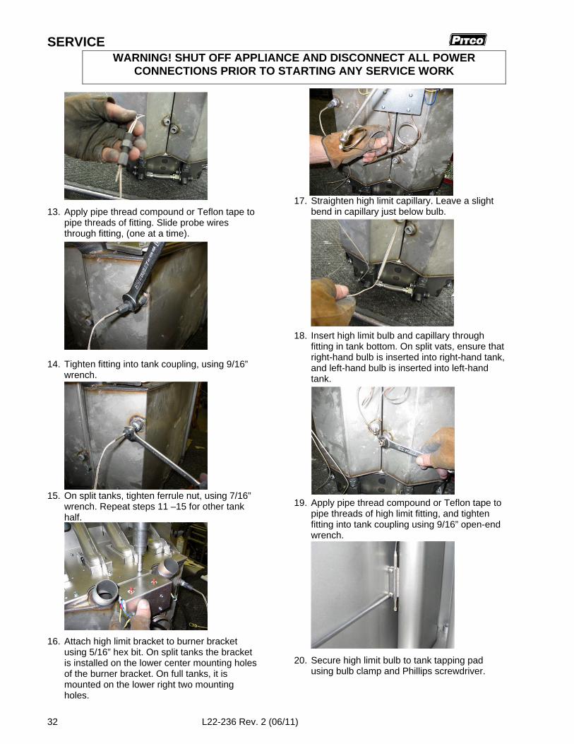
13. Apply pipe thread compound or Teflon tape topipe threads of fitting. Slide probe wiresthrough fitting, (one at a time).
14. Tighten fitting into tank coupling, using 9/16”wrench.
15. On split tanks, tighten ferrule nut, using 7/16”wrench. Repeat steps 11 –15 for other tankhalf.
16. Attach high limit bracket to burner bracketusing 5/16” hex bit. On split tanks the bracketis installed on the lower center mounting holesof the burner bracket. On full tanks, it ismounted on the lower right two mountingholes.
17. Straighten high limit capillary. Leave a slightbend in capillary just below bulb.
18. Insert high limit bulb and capillary throughfitting in tank bottom. On split vats, ensure thatright-hand bulb is inserted into right-hand tank,and left-hand bulb is inserted into left-handtank.
19. Apply pipe thread compound or Teflon tape topipe threads of high limit fitting, and tightenfitting into tank coupling using 9/16” open-endwrench.
20. Secure high limit bulb to tank tapping padusing bulb clamp and Phillips screwdriver.
WARNING! SHUT OFF APPLIANCE AND DISCONNECT ALL POWERCONNECTIONS PRIOR TO STARTING ANY SERVICE WORK
MGII and MG2T GAS FRYER SERVICE
L22-236 Rev. 2 (06/11) 33
21. On full tanks, the slide the probe through theears of the bulb clamp, and then tighten clampto tapping pad with high limit bulb securedbeneath the clamp.
22. On full tanks, tighten the probe ferrule nutusing a 7/16” wrench.
23. Tighten the capillary ferrule nut using a 5/16”:open-end wrench. Do not overtighten theferrule nut, as it will shear capillary tubing. ¼turn beyond hand tight should providesufficient sealing.
24. For split tanks, repeat steps 17 – 20 and 23 forthe other tank half.
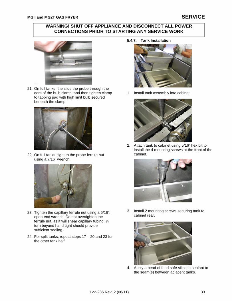
5.4.7. Tank Installation
1. Install tank assembly into cabinet.
2. Attach tank to cabinet using 5/16” hex bit toinstall the 4 mounting screws at the front of thecabinet.
3. Install 2 mounting screws securing tank tocabinet rear.
4. Apply a bead of food safe silicone sealant tothe seam(s) between adjacent tanks.
WARNING! SHUT OFF APPLIANCE AND DISCONNECT ALL POWERCONNECTIONS PRIOR TO STARTING ANY SERVICE WORK

SERVICE
34 L22-236 Rev. 2 (06/11)
5. Install channel strip(s) between adjacent frytanks.
6. Slide splashback in place over rear of cabinetand tank. Install screws securing splashback torear of tank using a flat bladed screwdriver.
7. Install screws securing splashback to cabinetrear using a 5/16” bit.
8. For filter equipped fryers, reconnect returntubing to return valves using 1-1/16” wrench.
9. For filter equipped fryers, install return valvehandle through hole in valve link. Install flatand spring washer, and hold in place withpliers. Install cotter pin through hole in link tosecure handle.
10. Install cabinet rear bottom cover
11. Reinstall top deck, front panel heat shield(s),bottom rail and front panel bezel. See Section5.1.4.
12. For filter equipped fryers, install return valvehandle bracket to burner rack using 5/16” hexbit.
WARNING! SHUT OFF APPLIANCE AND DISCONNECT ALL POWERCONNECTIONS PRIOR TO STARTING ANY SERVICE WORK
MGII and MG2T GAS FRYER SERVICE
L22-236 Rev. 2 (06/11) 35
13. For filter equipped fryers, place return valvehandle rod in slot in bracket, and installretainer using 5/16” hex bit.
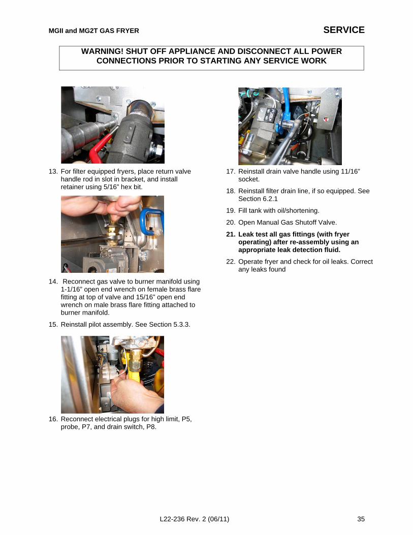
14. Reconnect gas valve to burner manifold using1-1/16” open end wrench on female brass flarefitting at top of valve and 15/16” open endwrench on male brass flare fitting attached toburner manifold.
15. Reinstall pilot assembly. See Section 5.3.3.
16. Reconnect electrical plugs for high limit, P5,probe, P7, and drain switch, P8.
17. Reinstall drain valve handle using 11/16”socket.
18. Reinstall filter drain line, if so equipped. SeeSection 6.2.1
19. Fill tank with oil/shortening.
20. Open Manual Gas Shutoff Valve.
21. Leak test all gas fittings (with fryeroperating) after re-assembly using anappropriate leak detection fluid.
22. Operate fryer and check for oil leaks. Correctany leaks found
WARNING! SHUT OFF APPLIANCE AND DISCONNECT ALL POWERCONNECTIONS PRIOR TO STARTING ANY SERVICE WORK
SERVICE
36 L22-236 Rev. 2 (06/11)
6. Component Replacement – Filter6.1. Pump and Pump Box
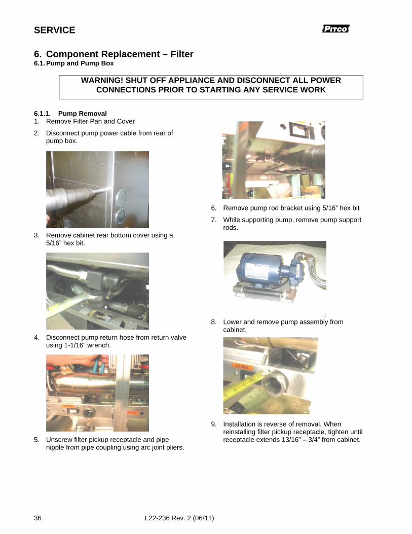
6.1.1. Pump Removal1. Remove Filter Pan and Cover
2. Disconnect pump power cable from rear ofpump box.
3. Remove cabinet rear bottom cover using a5/16” hex bit.
4. Disconnect pump return hose from return valveusing 1-1/16” wrench.
5. Unscrew filter pickup receptacle and pipenipple from pipe coupling using arc joint pliers.
6. Remove pump rod bracket using 5/16” hex bit
7. While supporting pump, remove pump supportrods.
8. Lower and remove pump assembly fromcabinet.
9. Installation is reverse of removal. Whenreinstalling filter pickup receptacle, tighten untilreceptacle extends 13/16” – 3/4” from cabinet.
WARNING! SHUT OFF APPLIANCE AND DISCONNECT ALL POWERCONNECTIONS PRIOR TO STARTING ANY SERVICE WORK
MGII and MG2T GAS FRYER SERVICE
L22-236 Rev. 2 (06/11) 37
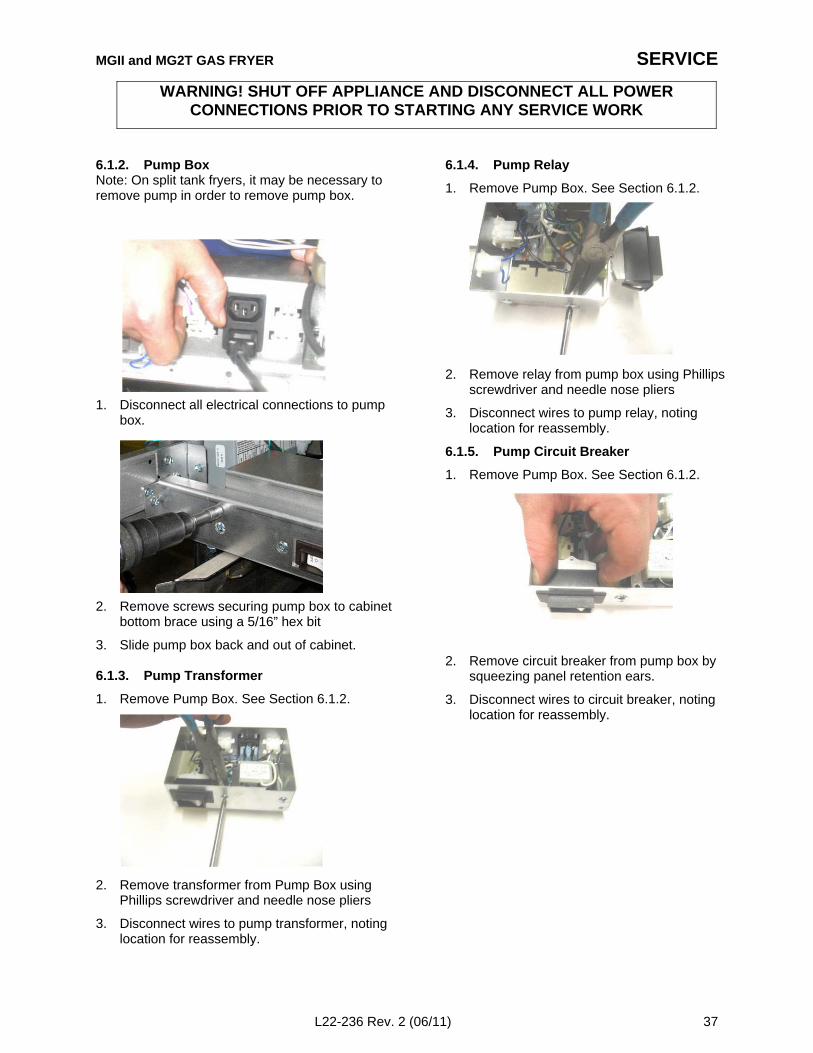
6.1.2. Pump BoxNote: On split tank fryers, it may be necessary toremove pump in order to remove pump box.
1. Disconnect all electrical connections to pumpbox.
2. Remove screws securing pump box to cabinetbottom brace using a 5/16” hex bit
3. Slide pump box back and out of cabinet.
6.1.3. Pump Transformer
1. Remove Pump Box. See Section 6.1.2.
2. Remove transformer from Pump Box usingPhillips screwdriver and needle nose pliers
3. Disconnect wires to pump transformer, notinglocation for reassembly.
6.1.4. Pump Relay
1. Remove Pump Box. See Section 6.1.2.
2. Remove relay from pump box using Phillipsscrewdriver and needle nose pliers
3. Disconnect wires to pump relay, notinglocation for reassembly.
6.1.5. Pump Circuit Breaker
1. Remove Pump Box. See Section 6.1.2.
2. Remove circuit breaker from pump box bysqueezing panel retention ears.
3. Disconnect wires to circuit breaker, notinglocation for reassembly.
WARNING! SHUT OFF APPLIANCE AND DISCONNECT ALL POWERCONNECTIONS PRIOR TO STARTING ANY SERVICE WORK
SERVICE
38 L22-236 Rev. 2 (06/11)
6.2. Drain Line
6.2.1. Drain Line Removal
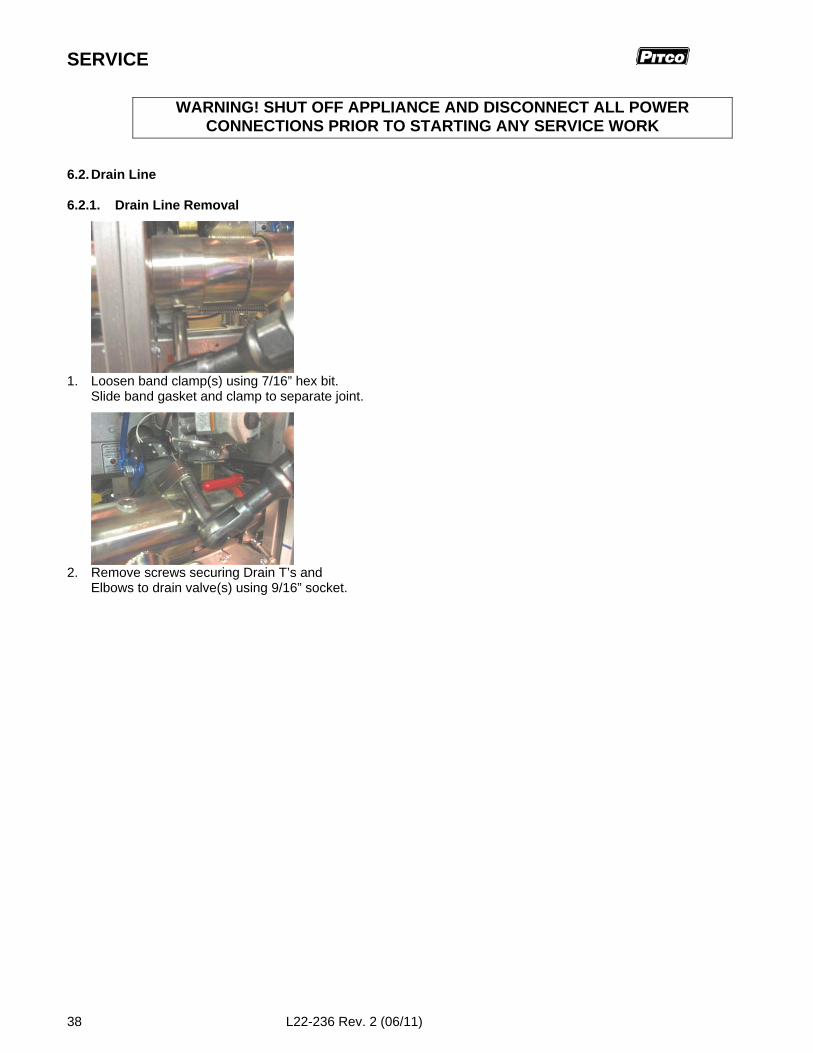
1. Loosen band clamp(s) using 7/16” hex bit.Slide band gasket and clamp to separate joint.
2. Remove screws securing Drain T’s andElbows to drain valve(s) using 9/16” socket.
WARNING! SHUT OFF APPLIANCE AND DISCONNECT ALL POWERCONNECTIONS PRIOR TO STARTING ANY SERVICE WORK
MGII and MG2T GAS FRYER SERVICE
L22-236 Rev. 2 (06/11) 39
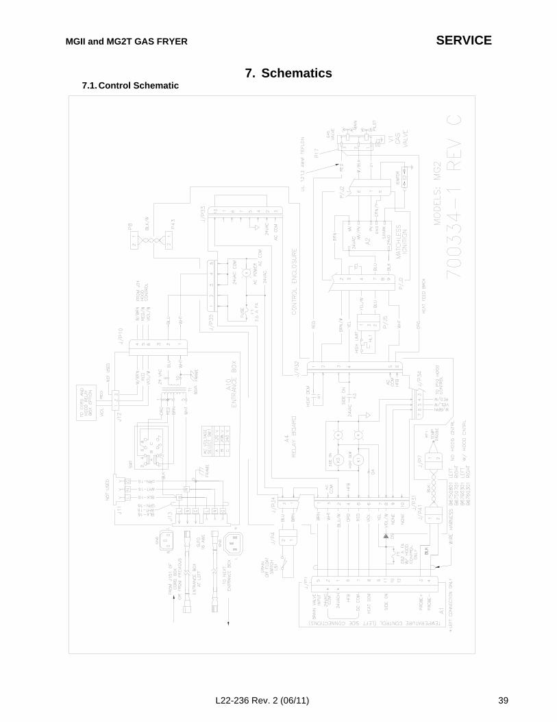
7. Schematics7.1. Control Schematic
SERVICE
40 L22-236 Rev. 2 (06/11)
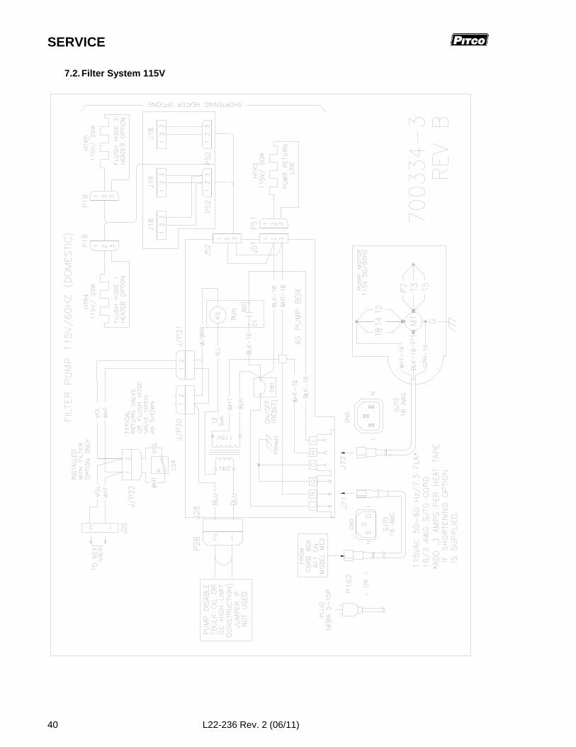
7.2. Filter System 115V
MGII and MG2T GAS FRYER SERVICE
L22-236 Rev. 2 (06/11) 41
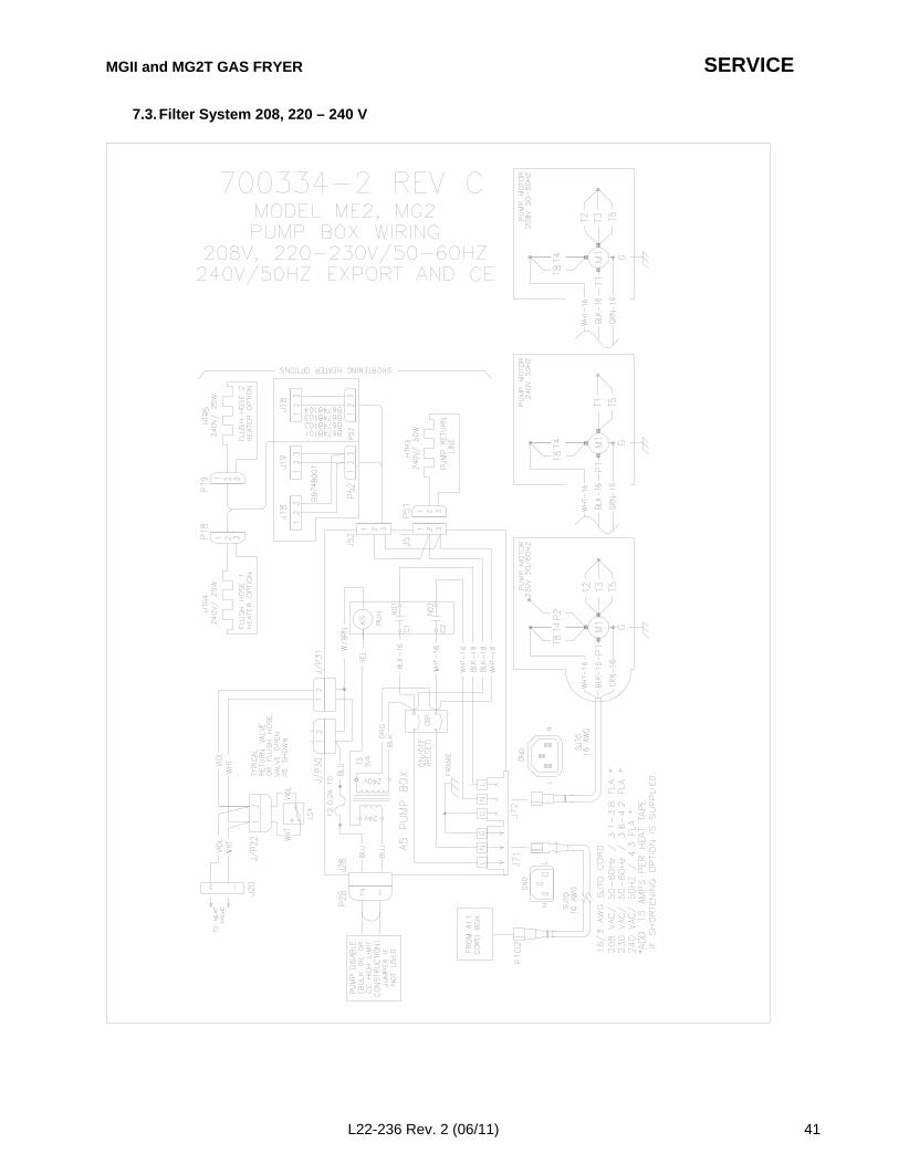
7.3. Filter System 208, 220 – 240 V
SERVICE
42 L22-236 Rev. 2 (06/11)
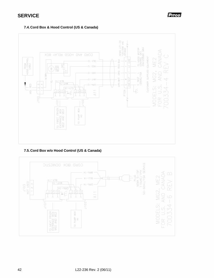
7.4. Cord Box & Hood Control (US & Canada)
7.5. Cord Box w/o Hood Control (US & Canada)

MGII and MG2T GAS FRYER SERVICE
L22-236 Rev. 2 (06/11) 43
7.6. Cord Box (Export & CE)

L22-236 Rev 2 (06/11)
In the event of problems with orquestions about your order, pleasecontact the Pitco Frialator factory at:(603) 225-6684 World WideWebsite Address: www.pitco.com
In the event of problems with or questionsabout your equipment, please contact thePitco Frialator Authorized Service and Partsrepresentative (ASAP) covering your area, orcontact Pitco at the numbers listed to the left.
MAILING ADDRESS – P.O. BOX 501, CONCORD, NH 03302-0501SHIPPING ADDRESS – 10 FERRY ST., CONCORD, NH 03301