Embed Size (px)
Citation preview

COMPANY DOC. No. L290-AH-PLN-10204 REV.
JKC DOC. No. S-0290-1242-C486 11 COMPANY CONTRACT No. 800224 Review Class. 1
JGC JOB No. 0-6037-21 KBR JOB No. F034 CHIYODA JOB No. 11051
SHEET 1 OF 41
REV. DATE ISSUE PURPOSE PREPARED CHECKED APPROVED
7 01-Mar-16 IFC T. Giltrap A. Black S. Mayne
8 29-Sep-16 IFC A. Robertson H. Durrant S. Mayne
9 10-Oct-16 IFC A. Robertson H. Durrant S. Mayne
10 26-Sep-17 IFC T. Elder L. Manal K. Zic
11 14-Oct-17 IFC T.Elder L. Manal K. Zic
FORM EPC-1 5
INPEX Operations Australia Pty Ltd
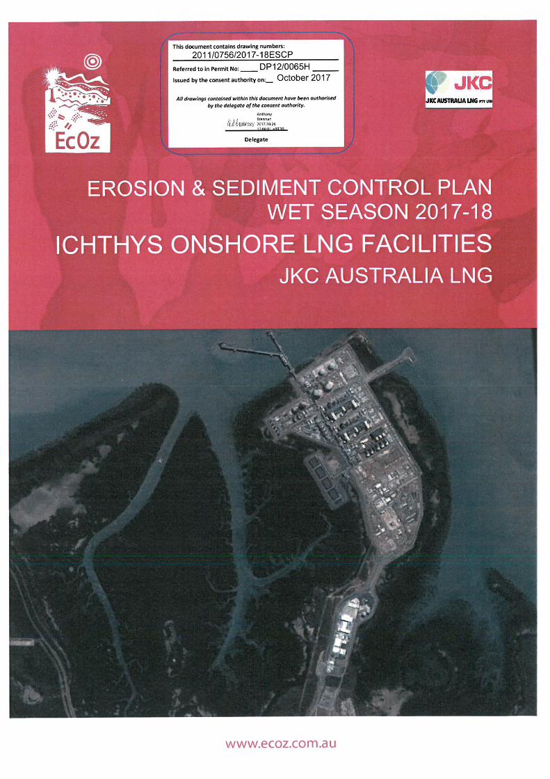
ICHTHYS ONSHORE LNG FACILITIES
EROSION AND SEDIMENT CONTROL PLAN
INDRA14-OCT-2017
Client Issue

EcOz Pty Ltd ABN 81 143 989 0395 Tel: 08 898111005 e-mail: [email protected]
5 website: www.ecoz.com.au
Darwin, Northern TerritoryLevel 3 75 Woods St (cnr Lindsay)GPO Box 381Darwin Northern Territory 0801
Our Ref: 158886Job No: EZ17094Enquiries to: Tim Elder [email protected]
Date: 27 September 2017
Kresho ZicProject Environmental ManagerIchthys ProjectJKC Australia LNG Pty LtdBladin Point, Channel Island Road, NT, 0820
Email: [email protected]
Re: Erosion and Sediment Control Plan – Wet Season 2017-18
Dear Kresho,
I make reference to the document Erosion and Sediment Control Plan Wet Season 2017-18, IchthysOnshore LNG Facilities Rev 2 (Document ID 158292 - the ESCP), submitted to JKC on the 23rd
September 2017. This ESCP was prepared by a Certified Professional in Erosion & SedimentControl (Tim Elder – CPESC #4399), consistent with the intent of the industry guideline ‘BestPractice Erosion and Sediment Control Guidelines’ (IECA 2008).
The ESCP includes an assessment of the erosion and sedimentation risks reflecting the currentstage of project construction, and anticipated activities for the upcoming wet season. The ESCPincludes information, techniques and procedures to enable JKC to implement effective soil and watermanagement strategies in accordance with Project approval requirements.
As a CPESC, I certify the ESCP & associated drawings as fit for purpose for the 2017-18 wetseason.
Upon implementation of ESCP recommendations by Subcontractors and JKC, a further letter ofverification will be issued.
Yours sincerely,
Tim ElderManaging ConsultantEcOz Environmental ConsultantsCPESC #4399
EcOzEnvironmental
Consultants
NorthernAustralian
Consultants
in
Environmentalimpact
assessments
Environmentalmanagementplanning and
systems
Terrestrial andaquatic ecological,
flora & faunastudies
Water qualitymonitoring andassessments
Natural resourcemanagement
planning
Environmental andsocial
offsets
Communityconsultation
Environmentalmonitoring, auditingand investigations
Developmentplanning
GIS mapping andsupport
INDRA14-OCT-2017
Client Issue

1.
EROSION & SEDIMENT CONTROL PLANWET SEASON 2017-18
ICHTHYS ONSHORE LNG FACILITIESJKC AUSTRALIA LNG
INDRA14-OCT-2017
Client Issue

Client: JKC Australia LNG iiDoc Title: Erosion & Sediment Control Plan Wet Season 2017-18. Ichthys Onshore LNG Facilities
DOCUMENT CONTROL RECORD
Job number EZ17094
Document ID 158292
Project manager Tim Elder
Author(s) Tim Elder
CPESCCertification
Tim Elder(CPESC # 4399)
Approved by Ray Hall
Approval date 23 September 2017
Revision Issue date Document history Reviewer
0 7 Sept 2017 Report preparation by author HD1 8 Sept 2017 Draft for Client review Client2 23 Sept 2017 Sent to client -
Recipients are responsible for eliminating all superseded documents in their possession.
EcOz Pty Ltd.ABN: 81 143 989 039Winlow House, 3rd Floor75 Woods StreetDARWIN NT 0800GPO Box 381, Darwin NT 0800
Telephone: +61 8 8981 1100Facsimile: +61 8 8981 1102Email: [email protected]: www.ecoz.com.au
RELIANCE, USES and LIMITATIONSThis report is copyright and is to be used only for its intended purpose by the intended recipient, and is not to be copied or used in anyother way. The report may be relied upon for its intended purpose within the limits of the following disclaimer.
This study, report and analyses have been based on the information available to EcOz Environmental Consultants at the time ofpreparation. EcOz Environmental Consultants accepts responsibility for the report and its conclusions to the extent that the informationwas sufficient and accurate at the time of preparation. EcOz Environmental Consultants does not take responsibility for errors andomissions due to incorrect information or information not available to EcOz Environmental Consultants at the time of preparation of thestudy, report or analyses.
INDRA14-OCT-2017
Client Issue
Client: JKC Australia LNG iiiDoc Title: Erosion & Sediment Control Plan Wet Season 2017-18. Ichthys Onshore LNG Facilities
TABLE OF CONTENTS
1 Introduction ........................................................................................................................................... 5
1.1 Purpose & Scope ........................................................................................................................... 5
2 Site description ..................................................................................................................................... 8
2.1 Existing Environment ..................................................................................................................... 8
2.2 Sensitive Receptors ....................................................................................................................... 8
2.3 Rainfall .......................................................................................................................................... 8
2.4 Topography and Drainage .............................................................................................................. 9
2.5 Soils .............................................................................................................................................. 9
2.6 Progressive stabilisation................................................................................................................. 9
3 Erosion hazard and risk .......................................................................................................................10
3.1 Erosion hazard ..............................................................................................................................10
3.1.1 Rainfall erosivity (R–factor) ....................................................................................................103.1.2 Erodibility (K-factor)................................................................................................................103.1.3 Slope (LS–factor) ...................................................................................................................113.1.4 Cover and management factor (C–factor) ...............................................................................113.1.5 Erosion control practice factor (P–factor) ................................................................................11
3.2 Erosion risk ...................................................................................................................................12
4 Stormwater ..........................................................................................................................................13
4.1 Clean and dirty water ....................................................................................................................13
4.2 Stormwater management ..............................................................................................................13
5 Erosion and sediment control measures ...............................................................................................14
5.3 Erosion Control .............................................................................................................................14
5.4 Sediment control ...........................................................................................................................14
5.4.1 Type 1 controls ......................................................................................................................155.4.2 Type 2 controls ......................................................................................................................155.4.3 Type 3 controls ......................................................................................................................15
6 Specific areas & activities.....................................................................................................................17
7 ESCP management .............................................................................................................................19
7.1 Implementation .............................................................................................................................19
7.2 ESCP updates and amendments ..................................................................................................19
8 References ..........................................................................................................................................21
TablesTable 1. Subcontractor ESCPs and associated work areas ......................................................................... 6Table 2. C-factors for various surface applications .....................................................................................11Table 3. Monthly erosion risk rating ...........................................................................................................12Table 4. Sediment control selection ............................................................................................................16Table 5. Objectives, targets and indicators for erosion and sediment management .....................................19
INDRA14-OCT-2017
Client Issue

Client: JKC Australia LNG ivDoc Title: Erosion & Sediment Control Plan Wet Season 2017-18. Ichthys Onshore LNG Facilities
FiguresFigure 1. Map of project area (Inpex Operations Australia 2017) ................................................................. 7Figure 2. Mean seasonal rainfall for Darwin ................................................................................................. 8
AppendicesAppendix A SOIL LOSS CALCULATIONS
Appendix B ESC SITE DRAWINGS
Appendix C TYPICAL ESC DRAWINGS
AcknowledgementsEcOz acknowledges the work undertaken by CDM Smith in preparation of the JKC 2016-2017 Wet SeasonErosion and Sediment Control Plan (JKC Australia LNG 2016).
INDRA14-OCT-2017
Client Issue
Client: JKC Australia LNG 5Doc Title: Erosion & Sediment Control Plan Wet Season 2017-18. Ichthys Onshore LNG Facilities
1 INTRODUCTION
INPEX Operations Australia Pty Ltd (Company) are developing the Ichthys Field in the Browse Basin Areaoff the Northwest coast of Australia for the purpose of producing LNG and extracting condensate and LPGfor export.
JKC Australia LNG Pty Ltd (Contractor), a company established under the laws of Australia, was awarded acontract by Company, to engineer, procure, construct and commission the Ichthys Onshore LNG FacilitiesProject (the project), located at Bladin Point, Darwin, Northern Territory, Australia. The LNG Plant, in its initialphase, will be capable of producing liquefied natural gas (LNG) from two LNG trains.
Contractor has engaged EcOz Pty Ltd (EcOz) to prepare and certify an Erosion and Sediment Control Plan(ESCP) for the project site for the 2017-18 wet season. This ESCP is certified by Tim Elder (CPESC #4399).
This ESCP provides an updated assessment of erosion risk and associated management recommendationsconsistent with the current stage of construction, while providing continuity and consistency with the2016-17 Erosion and Sediment Control Plan prepared by CDM Smith (JKC Australia LNG 2016a).
1.1 Purpose & Scope
This ESCP has been developed based on the project construction program for the 2017-18 wet season (1October 2017 – 30 April 2018). The project extent is provided in Figure 1, with the ESCP applying to variousconstruction, commissioning and operations areas within the project boundary. The Extractive Minerals Area(EMA) and Area 1888 are addressed under separate ESCPs.
The purpose of this CPESC (Certified Professional in Erosion and Sediment Control) certified ESCP is to:
∂ Meet the regulatory and environmental approval conditions set out in the Environment Protection
Agency (EPA) approved Ichthys Onshore LNG Facilities, Construction EnvironmentalManagement Plan (Inpex Operations Australia 2017) and Development Permit DP12/0065 (theBladin Point site development permit).
∂ Provide an erosion assessment by a CPESC and identify the controls to be implemented toeffectively manage erosion, and subsequent sediment mobilisations, during the 2017/18 wetseason.
∂ Provide ESC recommendations and designs consistent with the International Erosion ControlAssociation (IECA) guidelines Best Practice Erosion and Sediment Control (IECA 2008),
∂ Ensure that ESCP’s provided by Subcontractors are in accordance with IECA guidelines (IECA2008). Subcontractor certified 2017-18 wet season ESCPs reviewed as part of this ESCP aredetailed within Table 1.
∂ Ensure ESCs are consistent across the project, and reflect changes in site conditions asconstruction progresses.
This plan nominates suitable ESCs, consistent with the current construction schedule, which will beimplemented to achieve environmental compliance in readiness for the commencement of the wet season.ESCs shall be progressively reviewed against the construction schedule progress to determine suitability ofcontrols and/or refinement of this plan.
INDRA14-OCT-2017
Client Issue

Client: JKC Australia LNG 6Doc Title: Erosion & Sediment Control Plan Wet Season 2017-18. Ichthys Onshore LNG Facilities
Table 1. Subcontractor ESCPs and associated work areas
Subcontractor Package Work Area(s) CPESC
CivMec Construction & Engineering CCPP E600 Tim ElderEcOz Pty Ltd
Wagners CVL-4 E800 Jacob Tobin CDMSmith, recertified byTim ElderEcOz Pty Ltd
John Holland Territoria Civil CVL-9 Multiple areas across site Holly DurrantCDM Smith
Kentz ELE-1 C300, C400, E600, HR11 Mark PassfieldSEEC
UGL Kentz MEC-1 E600 Andrew MacLeodSEEC recertified byTim ElderEcOz Pty Ltd
Ventia Pty Ltd OPS-1 Multiple areas across site Tim ElderEcOz Pty Ltd
AMJV PSI-1 A100, A200, E600, B800 Andrew McLeodSEEC
Kaefer Integrated Services PSI-2 /SCF-2
Multiple areas across site Tim ElderEcOz Pty Ltd
Cape Australia PSI-3 Multiple areas across site Tim ElderEcOz Pty Ltd
Kawasaki Heavy Industries Ltd TNK-1 C100, C200, C300, E600 Tim ElderEcOz Pty Ltd
Veolia WST-1 Multiple areas across site Tim ElderEcOz Pty Ltd
Note:
Subcontractor package COM-1 (EnerMech) is undertaking commissioning works and erosion risk isconsidered low and controls are incorporated into this ESCP. MED-1 (Falck) and SEC-1 (WilsonSecurity) are service contractors, with any required controls also incorporated into this ESCP. OPS-1 (ESS Larrakia) operates the Manigurr-ma accommodation village, which is now classified as anoperation site with a very low erosion risk. TASK erosion hazard assessments have been completedfor SCF-1 (MAS) and MEC-2 packages by Contractor and reviewed by Tim Elder (CPESC #4399).These packages do not require stand-alone ESCPs.
INDRA14-OCT-2017
Client Issue

Client: JKC Australia LNG 7Doc Title: Erosion & Sediment Control Plan Wet Season 2017-18. Ichthys Onshore LNG Facilities
Figure 1. Map of project area (Inpex Operations Australia 2017)
INDRA14-OCT-2017
Client Issue

Client: JKC Australia LNG 8Doc Title: Erosion & Sediment Control Plan Wet Season 2017-18. Ichthys Onshore LNG Facilities
2 SITE DESCRIPTION
The characteristics of site with potential to be impacted by or influence erosion (and subsequent mobilisationof sediment through ‘dirty’ water runoff from the site) are described below.
2.1 Existing Environment
The project, located at Bladin Point in Darwin Harbour, NT, is bound by Lightning Creek on the westernboundary, by East Arm (part of Darwin Harbour) to the north, and by the mouth of the Elizabeth River on theeastern boundary (Inpex Operations Australia 2017).
2.2 Sensitive Receptors
Sensitive receptors external to the project site include protected heritage sites (NT Heritage Act) locatedsouth / south-east of the site, mangrove communities, Lightning Creek, East Arm Creek, Elizabeth River andDarwin Harbour as a whole.
2.3 Rainfall
Bladin Point is located within a tropical monsoonal bioregion and therefore experiences two distinct seasons.The wet season runs predominantly from October to April and brings high rainfall, with the dry seasonrunning from May to September and bringing drier and cooler conditions. For the purposes of this ESCP, thewet season is defined as October 1 to April 30. Based on Bureau of Meteorology (BOM) mean rainfall datafrom Weather Station 014015 (located at Darwin’s International Airport), the mean annual rainfall is1727.5 mm with rain falling on an average of 112.6 days. Figure 2 outlines the mean monthly rainfallrecorded at Darwin Airport between 1941 and 2012. The annual mean evaporation rate is 2630 mm.
Figure 2. Mean seasonal rainfall for Darwin
0
50
100
150
200
250
300
350
400
450
Rain
fall
(mm
)
Monthly Rainfall Data
INDRA14-OCT-2017
Client Issue

Client: JKC Australia LNG 9Doc Title: Erosion & Sediment Control Plan Wet Season 2017-18. Ichthys Onshore LNG Facilities
2.4 Topography and Drainage
The topography of the project site has been altered through bulk and detailed earthworks, trenching andabove ground construction activities during the initial project stages. Finished earthworks levels are between6.9 and 7.4 m Australian Height Datum (AHD). The slope of the processing site is generally 1 % or less infinal design (excluding active work zones and excavations), draining to a perimeter drainage network (InpexOperations Australia 2016a).
2.5 Soils
The underlying soils associated with the processing plant site predominantly comprise the Hotham soil familyreworked during bulk earthworks (URS 2009). Other soil families include the Bladin, Koolpinyah and to alesser extent the Euro and Rinamatta soil families.
In 2009, URS identified main soil groups along the onshore pipeline including Hydrosols (soil families - Euroand Maand) and Kandasols (soil families – Bladin, Hotham and Koolpinyah).
The Euro soils family is formed on intertidal flats under mangrove vegetation with saline tidal influence. TheMaand soil family is shallow to moderately deep soils formed under supratidal flats mainly void of vegetation.
The URS 2009 report nominated the Bladin, Hotham and Koolpinyah soil families as all being deep earthysoils with well-structured A Horizons. The Koolpinyah soil family is the only family in the area that has asubsoil that is sodic and is considered dispersive and considered to have a high erosion risk (InpexOperations Australia 2016a).
2.6 Progressive stabilisation
Site erosion hazard is being progressively reduced as construction is completed and areas reach thecommissioning and operation phases. For the commencement of the 2017-18 wet season, the drainage andsurface condition of site is characterised by the following:
∂ Completion of permanent surface stabilisation for the following areas:o Condensate tankso Flare pado Jettyo Module offloading facilityo Gas reception areao Onshore gas export pipeline (GEP) corridoro Combined operations complex and plant area
∂ Permanent sealing of access and haul roads including Site Access Road (SAR); SimultaneousOperations (Simops) Road; Construction Roads 1, 4, 6 and 9 (part); Haul Roads 1 (part), 9, 10A and12C.
∂ Permanent concrete U-ditch drainage network installed and functional across > 95 % of site.
∂ Protection of temporary drainage network with lining of channels.
∂ Maintenance of unsealed access and haul road through application of fine crushed rock (FCR),cement stabilisation, crushed rock.
∂ Provision of temporary surface protection within work areas through application of FCR, chip-seal,rock, gypsum, soil stabiliser.
INDRA14-OCT-2017
Client Issue

Client: JKC Australia LNG 10Doc Title: Erosion & Sediment Control Plan Wet Season 2017-18. Ichthys Onshore LNG Facilities
3 EROSION HAZARD AND RISK
3.1 Erosion hazard
Erosion hazard within individual sub-catchments is assessed using the Revised Universal Soil Loss Equation– RUSLE (IECA 2008). This is commonly used to predict the long term, average, annual soil loss from sheetand rill erosion under specified management conditions. This assessment methodology suits the fragmentednature of work areas which make up the project.
The RUSLE is represented by the following equation:
A = R K LS P C
where:
Factor Description Value CommentA computed soil loss (tonnes/ha/yr) variable As calculated per catchment
R rainfall erosivity factor 13738 derived from Darwin HarbourAdvisory Committee Research Group
K soil erodibility factor 0.036 based on information gathered duringEIS process
LS slope length/gradient factor variable Based on catchment characteristics.IECA 2008 – Section E3.3
P erosion control practice factor 1.3 Construction phase conditionSection 3.1.5
C ground cover and managementfactor
variable Based on catchment characteristics.Section 3.1.4
3.1.1 Rainfall erosivity (R–factor)
The rainfall erosivity factor (R-factor) is a measure of the ability of rainfall to cause erosion. It is a product oftwo components: total energy (E) and maximum 30-minute intensity for each storm (Landcom 2004). TheR-factor is an input component in measuring estimated soil loss using the RUSLE calculation. The annualR-factor for the site has been nominated as 13738, derived from the Darwin Harbour Advisory CommitteeResearch Group and agreed upon in initial 2011 ESC meetings with NT Government (Department of NaturalResources, Environment, the Arts and Sport – NRETAS) to accurately represent the rainfall erosivity of theDarwin region (Inpex 2016a).
3.1.2 Erodibility (K-factor)
The K-factor is a numerical representation of the ability of soils to resist the erosive energy of rain (IECA2008). While it is recommended the K-factor be derived from laboratory analysis of the local soils, this ESCPhas been developed using the information gathered during the Project’s EIS phase. A K-factor of 0.036 hasbeen adopted for all work areas, with the exception of the GEP corridor beach valve for which a K-factor of0.04 has been adopted.
INDRA14-OCT-2017
Client Issue

Client: JKC Australia LNG 11Doc Title: Erosion & Sediment Control Plan Wet Season 2017-18. Ichthys Onshore LNG Facilities
3.1.3 Slope (LS–factor)
The nominal slope grades for the processing plant site sub-catchments range from 0.5% to 1% (1%adopted). The slope identified for the GEP corridor beach valve is 2%. Maximum slope length for each sub-catchment has been adopted for soil loss calculations.
3.1.4 Cover and management factor (C–factor)
Ground cover on site comprises a variety of protective finishes including concrete pavements, roofing,bitumen, rock, vegetation, FCR, matting and polymer products, in addition to limited areas of exposed soil.Site haul roads and construction roads within the main construction site, while stabilised with chip-seal,cement and FCR, require ongoing maintenance to minimise sediment generation as a result of wet weatherand heavy traffic. As such, a nominal 20% cover (C-factor of 0.45) has been assumed for these roads. Otherroads which have been permanently sealed (refer Section 2.6) and are well maintained, are assessed asclean water surfaces (C-factor of 0). C-factors for various surface finishes are summarised inTable 2.
Table 2. C-factors for various surface applications
Surface type % cover C-factor
Concrete, bitumen, roofing, 40-80 rock, FCR (no traffic) 100 0
Landscaping 75 - 100 0.04 - 0
Chip-seal (good condition), FCR (no traffic), soil stabiliser,geofabric cover
80 - 100 0.025 - 0
FCR (traffic, well maintained) 40 - 60 0.215 – 0.09
Competent gravel layer, hardstand 70 – 80 0.05 – 0.025
FCR (heavy traffic, minimal maintenance), chip-seal (heavy traffic,degraded)
20 - 25 0.44 – 0.37
Bare soil, erosive surface 0 - 20 1 - 0.44
3.1.5 Erosion control practice factor (P–factor)
The P-factor measures the combined effect of all support practices and management variables. It alsorepresents structural methods for controlling erosion (IECA 2008). The nominated P-factor for all areaswithout permanent stable groundcover is 1.3 (based on the default construction phase condition).
Updated potential soil loss calculations for defined project catchments for the 2017-18 wet season arecontained within Appendix A. Nominated catchments generally reflect collective runoff discharge points forwork areas within the project site (refer Appendix B).
The placement of hardstand surfaces (concrete, stabilised fine crushed rock (FCR), 40-80 rock, pavementetc.) across the project site has the predictable effect of progressively reducing overall soil loss (reducing Cfactor and K-factor). Soil loss is further reduced by the low slope of work areas (0.5 - 1%), which reduces theerosive potential of surface runoff across site.
For all catchments assessed within this ESCP, potential soil loss is Class 1 - very low erosion hazard (i.e.calculated as less than 75 tonnes/ha/yr or with disturbed catchment area of < 0.25 ha – refer Appendix A).
INDRA14-OCT-2017
Client Issue

Client: JKC Australia LNG 12Doc Title: Erosion & Sediment Control Plan Wet Season 2017-18. Ichthys Onshore LNG Facilities
3.2 Erosion risk
Erosion risk refers to the evaluation of the “risk” of soil erosion when consideration is given to both thedegree of erosion and the likelihood of the erosion occurring (IECA 2008). In the absence of a site specificrisk assessment procedure, erosion risk rating is determined from monthly rainfall erosivity (refer Section3.1.1).
Erosion risk ratings range from high to extreme for the top end wet season (Oct – Apr), with dry season riskvery low (May – Sept).
Table 3. Monthly erosion risk rating
Month Jan Feb Mar Apr May Jun Jul Aug Sep Oct Nov Dec
Erosivity 3572 2781 2124 514 0 0 0 0 0 322 906 1775
Rating Extreme Extreme Extreme High V.Low V.Low V.Low V.Low V.Low High High Extreme
INDRA14-OCT-2017
Client Issue

Client: JKC Australia LNG 13Doc Title: Erosion & Sediment Control Plan Wet Season 2017-18. Ichthys Onshore LNG Facilities
4 STORMWATER
4.1 Clean and dirty water
The Project CEMP (Table 6.4.1), defines stormwater as:
“runoff from rain events that has not contacted potentially contaminated areas on Site or has beencollected in a detention basin, excavation, trench, sump or other low points that has not hadopportunity to become contaminated”.
For the purposes of erosion and sediment control, stormwater can further be divided into ‘clean’ and ‘dirty’water as described below:
Clean water: Water that either enters site from an external source and has not been furthercontaminated by sediment within site; or water that has originated from thesite and is of such quality that it does not need to be treated in order toachieve the required water quality standard (IECA 2008).
Dirty water: Water not defined as clean, thereby requiring treatment with appropriatecontrols prior to release from site (IECA 2008).
Site clean water constitutes surface runoff from areas of non-erodible cover, including paving, concrete,completed landscaping, 40-80 rock, geotextile and stabilised hardstand. The appropriate treatment of dirtywater is determined by soil loss characteristics for the specific catchment (refer Section 5.4).
4.2 Stormwater management
Management of site stormwater is by transmission to the permanent drainage network, comprising U-ditchdrains and the perimeter regulating reservoir (which in turn discharges to the receiving environment).
This is achieved by:
∂ Diversion of clean water around active work areas.∂ Direct discharge of clean surface run-off from stable areas.∂ Treatment of dirty water with appropriate sediment controls/flocculants.
Surface runoff intercepted by excavations and trenches following rainfall will continue to be managed throughthe site Water Discharge Procedure (Inpex Operations Australia 2016b).
INDRA14-OCT-2017
Client Issue
Client: JKC Australia LNG 14Doc Title: Erosion & Sediment Control Plan Wet Season 2017-18. Ichthys Onshore LNG Facilities
5 EROSION AND SEDIMENT CONTROLMEASURES
5.1 Erosion & Sediment Control Plans
This ESCP incorporates the following:
∂ A review of the previous wet season ESCP (Inpex Operations Australia 2016a).∂ Erosion hazard assessments for all areas (including commissioning and operation areas).∂ Review of Subcontractor certified ESCPs.
Where ongoing work activities and areas are significantly modified from the anticipated 2017-18 constructionschedule during the course of the wet season, Progressive ESCPs may be required to reflect associatedchanges in site conditions and control requirements. This will be monitored during weekly inspections, withthe requirement for Progressive ESCPs to be determined by a CPESC.
5.2 Drainage Control
Drainage controls include measures for the diversion of clean water around and through the site, and thediversion of site runoff to enable treatment of sediment prior to release offsite.
Clean water drainage across site is primarily provided by concrete U-ditch channels and the regulatingreservoir, with geofabric stabilised channels providing temporary drainage in some areas.
Temporary drainage controls constructed as part of construction activities enable management of stormwaterwithin specific work areas. Controls typically include placement of hardstand material (to alleviate pondingand direct surface runoff to lined channels); and placement of protected (covered) berms to divert runoffaround open pits and excavations.
5.3 Erosion Control
Prevention of erosion is the primary approach for the prevention of adverse impacts associated withsedimentation. Construction activities are to be undertaken so as to reduce the duration of soil exposure toerosive forces (wind and water), either by holding the soil in place or by shielding it. Measures to be usedinclude:
∂ Implementation of appropriate drainage controls (as above).∂ Protection of soil surface through the ongoing placement of FCR, 40-80 rock, concrete surfaces,
pavement and soil binder.∂ Incorporation of gypsum to soil surfaces to improve soil structure and reduce erosion loss (see
Section 5.4.4).∂ Progressive permanent stabilisation of work areas (concrete, 40-80 rock, pavement, landscaping).
5.4 Sediment control
Sediment control measures are classified as being Type 1, Type 2 or Type 3 depending upon their ability totrap suspended sediments (IECA 2008 - Technical Note 4.1).
The design and location of sediment control structures is to be integrated with drainage and erosion controlsacross work areas. The decision on which control to use for a specific work area is based upon factors
INDRA14-OCT-2017
Client Issue

Client: JKC Australia LNG 15Doc Title: Erosion & Sediment Control Plan Wet Season 2017-18. Ichthys Onshore LNG Facilities
including calculated potential soil loss (RUSLE), historical performance, degree of site disturbance, existingand proposed infrastructure, practicality of construction, effectiveness, ease of maintenance and cost.
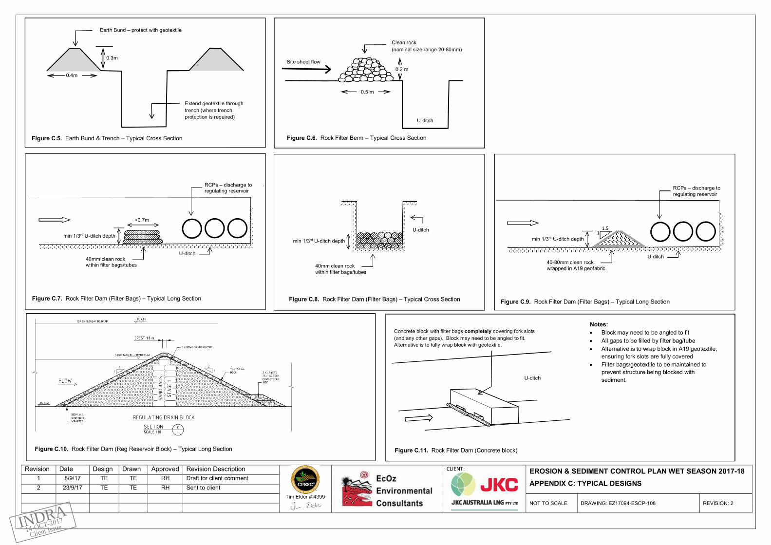
In addition to adopting measures as per IECA Standard Drawings, Subcontractors may adopt variations tostandard drawings (or as per Contractor Site Instruction) where it can be demonstrated that they are equallyas effective and meet the intent of IECA standards. This will be assessed by a CPESC where adopted.Typical designs for sediment controls are provided within Appendix C.
5.4.1 Type 1 controls
Type 1 controls (e.g. sediment basins) are not specifically required for treatment of surface runoff from any ofthe assessed catchments for the 2017-18 wet season (as per soil loss calculations – Appendix A)
5.4.2 Type 2 controls
As with Type 1 controls, soil loss calculations support the determination that Type 2 sediment controls arenot specifically required for the 2017-18 wet season (Appendix A). However, Type 2 controls have beennominated for use in various catchments based on effectiveness and historical performance to provide ahigher level of environmental protection, in addition to utilising existing in-situ controls. These controlsinclude:
Rock Filter Dam (RFD) – U-ditch
RFD’s will be utilised within sections of the U-ditch and regulating reservoir network for treatment ofchannelised runoff from work areas. There are three design variation for the use of RFDs in this application:
∂ RFDs formed by the incorporation of geotextile (eg. A19 bidum®) and a coarse rock filter.
∂ Filter dam formed by assembly of sediment tubes/bags to form a block.
∂ Filter dam formed by concrete block with geotextile filter outlets.
The existing blocked sections of the regulating reservoir (perimeter of site adjacent to C700 – refer AppendixA) may be retained as Type 2 RFD sediment controls for utilisation in dewatering activities, consistent withthe site Water Discharge Procedure (Inpex Operations Australia 2016b).
Rock Filter Dam (RFD) – Mangrove basin
During the 2017-18 wet season, the existing temporary basin adjacent to the Flare Pad (“Mangrove basin”) isto be utilised to actively dispose of stormwater. This basin will be operated as free-draining RFD device.
5.4.3 Type 3 controls
Type 3 sediment controls are the minimum standard of control required for all disturbed catchments for the2017-18 wet season. Type 3 controls to be implemented across site include:
Filter Bag/Tube – Type 2/3
Filter tubes are geotextile bags through which site runoff is directed to enable filtering and treatment ofsediment. They may also be used to construct a Type 2 RFD within U-ditch units (as described in Section5.4.2 above).
Rock berms – Type 3
Rock (20 – 40mm nominal size range) will be placed as a perimeter berm in several areas to filter sheet flowrunoff prior to entering permanent site drainage.
INDRA14-OCT-2017
Client Issue

Client: JKC Australia LNG 16Doc Title: Erosion & Sediment Control Plan Wet Season 2017-18. Ichthys Onshore LNG Facilities
Sediment fence – Type 3
Sediment fence will be used in locations where machine placement of rock berms is not practical (due tospace and access constraints).
Controls may also include a combination of the above (e.g. sediment fence with rock berm)
Table 4. Sediment control selection
Type 1 Type 2 Type 3
Soil Loss (RUSLE) >150 t/ha/yr 75 - 150 t/ha/yr < 75 t/ha/yr
Sediment capture 90% material> 0.045mm
90% material> 0.14mm
90% material> 0.42mm
Examples Sediment BasinRock Filter Dam
Mulch bermFilter sock
Sediment fenceRock berm
(Adapted from IECA, 2008)
5.4.4 Coagulants & Ameliorants
As with previous wet seasons, gypsum (calcium sulfate) may be utilised as a coagulant and soil stabiliserwhere considered necessary (as determined by environmental inspections). Where used, the primaryapplication method will be through spreading across catchment surfaces to reduce erosion loss and promotesettling of fine materials prior to runoff entering the permanent storm water drainage network. Applicationrate is typically 1 tonne/ha, applied at a frequency of every 6 weeks.
Similarly, lime (calcium carbonate) may also be used as a coagulant or correction of low pH water. Citricacid is used to correct elevated pH water where required.
5.5 Water Discharge
In-situ excavation water will be discharged as per Ichthys Onshore LNG Facilities, Water DischargeProcedure (L290-AB-PRC-10265, Rev 6) ((JKC Australia LNG 2016b).
INDRA14-OCT-2017
Client Issue

Client: JKC Australia LNG 17Doc Title: Erosion & Sediment Control Plan Wet Season 2017-18. Ichthys Onshore LNG Facilities
6 SPECIFIC AREAS & ACTIVITIES
6.1 Stockpile Sites
Stockpile sites are to be managed so as not to cause environmental harm as a result of sedimentation.Stockpile sites will be located and constructed consistent with the following principles:
∂ Located > 5m from existing remnant vegetation and hazard areas.
∂ Protected upslope by earth diversion banks to divert run-on water, and downslope by sedimentfence, covered earth bunds, rock checks or similar.
∂ protected to avoid or minimise erosion in accordance with the following IECA guidelines:
o >70% cover if inactive >20 days (October to November) (Table 4.4.4, IECA 2008)
o >70% cover if inactive >10 days (December to March) (Table 4.4.4, IECA 2008).
∂ Excavated material will be relocated to the EMA where practical in preference to stockpiling.
Where stockpile management cannot be completed in accordance with the above strategy, a riskassessment will be completed to determine the level of risk of potential environmental harm occurringdownstream of the stockpile as a result from sediment laden water discharge. This risk assessment will takeinto account existing controls both upstream, water diversion bunds/drains, and downstream watermanagement, including detention basins and water treatment. Where the level of risk of potentialenvironmental harm is low, covering of stockpiles may be acceptable. Stockpile stabilisation techniques mayinclude compaction, soil stabilisers, matting or other slope stabilisation products.
6.2 Stabilised exit points
Subcontractors will be responsible for maintaining access and egress points to specific work areas, ensuringsediment is not tracked outside of these work areas. Where sediment build up occurs on communal haulroads at vehicle exit points, a review of the controls will be undertaken and additional measures may beemployed. Measures to be implemented include:
∂ Rock pads at exit points (Appendix C – Figure C.2).
∂ Exit points constructed of stabilised sand (e.g. batch plant).
∂ FCR and 40-80mm rock stabilised access and exit points.
∂ Progressive stabilisation of access points by paving.
The specific stabilisation method identified will depend upon traffic volume, condition of external road (e.g.paved), potential for sediment tracking from work areas, and access requirements by heavy vehicles (i.e.quad tippers, heavy forklifts etc.). Subcontractors are to ensure exit points are regularly inspected andmaintained in accordance with IECA guidelines.
6.3 Excavation Management
Excavations will be protected to ensure the minimal amount of surface water ingress during rainfall, and alsoto enable intercepted rainfall to reach water quality release criteria as soon as practical. The preparation ofexcavations will be undertaken prior to the commencement of the wet season and include:
INDRA14-OCT-2017
Client Issue

Client: JKC Australia LNG 18Doc Title: Erosion & Sediment Control Plan Wet Season 2017-18. Ichthys Onshore LNG Facilities
∂ Construction and covering of perimeter bunds around excavations.∂ Construction/maintenance of stable ramp access points.∂ Trench floor stabilisation (e.g. stabilised sand, geotextile lining).∂ Incorporation of sumps to facilitate dewatering.
Options for dewatering include:
∂ In-situ treatment and discharge from site.∂ Transfer to storage for treatment and subsequent discharge from site.∂ Re-use within work areas as dust suppression, fill conditioning etc.
The discharge of water from site, in addition to reuse within site, will be consistent with the site WaterDischarge Procedure (Inpex Operations Australia 2016b).
Equipment for dewatering will include pumps, vacuum trucks, and water trucks.
6.4 U – Ditch Installation
Construction of the permanent site drainage (U-ditch) consists of installation of concrete precast drainageunits together with some in-situ construction. Newly completed U-ditch drainage will incorporate sedimentcontrol in the form of rock berm (for filtration of runoff prior to entering U-ditch) or RFD within the U-ditch.Sediment controls will be removed once the catchment is assessed as being adequately stabilised.
INDRA14-OCT-2017
Client Issue
Client: JKC Australia LNG 19Doc Title: Erosion & Sediment Control Plan Wet Season 2017-18. Ichthys Onshore LNG Facilities
7 ESCP MANAGEMENT
7.1 Implementation
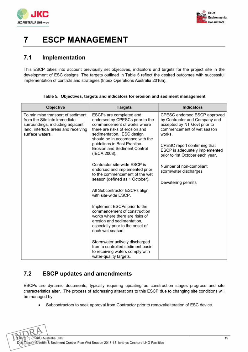
This ESCP takes into account previously set objectives, indicators and targets for the project site in thedevelopment of ESC designs. The targets outlined in Table 5 reflect the desired outcomes with successfulimplementation of controls and strategies (Inpex Operations Australia 2016a).
Table 5. Objectives, targets and indicators for erosion and sediment management
Objective Targets Indicators
To minimise transport of sedimentfrom the Site into immediatesurroundings, including adjacentland, intertidal areas and receivingsurface waters
ESCPs are completed andendorsed by CPESCs prior to thecommencement of works wherethere are risks of erosion andsedimentation. ESC designshould be in accordance with theguidelines in Best PracticeErosion and Sediment Control(IECA 2008).
Contractor site-wide ESCP isendorsed and implemented priorto the commencement of the wetseason (defined as 1 October).
All Subcontractor ESCPs alignwith site-wide ESCP.
Implement ESCPs prior to thecommencement of constructionworks where there are risks oferosion and sedimentation,especially prior to the onset ofeach wet season;
Stormwater actively dischargedfrom a controlled sediment basinto receiving waters comply withwater-quality targets.
CPESC endorsed ESCP approvedby Contractor and Company andaccepted by NT Govt prior tocommencement of wet seasonworks.
CPESC report confirming thatESCP is adequately implementedprior to 1st October each year.
Number of non-compliantstormwater discharges
Dewatering permits
7.2 ESCP updates and amendments
ESCPs are dynamic documents, typically requiring updating as construction stages progress and sitecharacteristics alter. The process of addressing alterations to this ESCP due to changing site conditions willbe managed by:
∂ Subcontractors to seek approval from Contractor prior to removal/alteration of ESC device.
INDRA14-OCT-2017
Client Issue

Client: JKC Australia LNG 20Doc Title: Erosion & Sediment Control Plan Wet Season 2017-18. Ichthys Onshore LNG Facilities
∂ An ESC tracking register to be maintained. The register shall identify proposed device type,design and implementation status. Devices will be monitored throughout the wet season, withany alterations/actions documented. This tracking process will be reviewed monthly.
∂ Updating of this 2017-18 ESCP as necessary during the wet season to reflect significantchanges to controls or site conditions.
This process will be managed by Contractor with assistance as required from Subcontractors and Company.To ensure that the Project site achieves its overall environmental objectives, site inspections will beundertaken as required to ensure installation and maintenance of controls is being carried out adequately.
INDRA14-OCT-2017
Client Issue

Client: JKC Australia LNG 21Doc Title: Erosion & Sediment Control Plan Wet Season 2017-18. Ichthys Onshore LNG Facilities
8 REFERENCES
Inpex Operations Australia Pty Ltd (2017). Ichthys Onshore LNG Facilities, Construction EnvironmentalManagement Plan(L092-AH-PLN-10001). [unpublished]
(IECA) International Erosion Control Association (2008). Best Practice Erosion and Sediment Control, Books1, 2 and 3. International Erosion Control Association (Australasia), Picton NSW.
JKC Australia LNG (2016a). Ichthys Onshore LNG Facilities, Erosion and Sediment Control Plan.[unpublished]
JKC Australia LNG. (2016b) Ichthys Onshore LNG Facilities, Water Discharge Procedure (L290-AB-PRC-10265, Rev 6) [unpublished].
Landcom (2004). Managing Urban Stormwater: Soils and Construction, Volume 1. NSW Government,Sydney.
URS Australia Pty Ltd (2009). Ichthys Gas Field Development Project: onshore topography, geology,geomorphology and soils study. [unpublished].
INDRA14-OCT-2017
Client Issue

Client: JKC Australia LNGDoc Title: Erosion & Sediment Control Plan Wet Season 2017-18. Ichthys Onshore LNG Facilities
APPENDIX A SOIL LOSS CALCULATIONS
INDRA14-OCT-2017
Client Issue
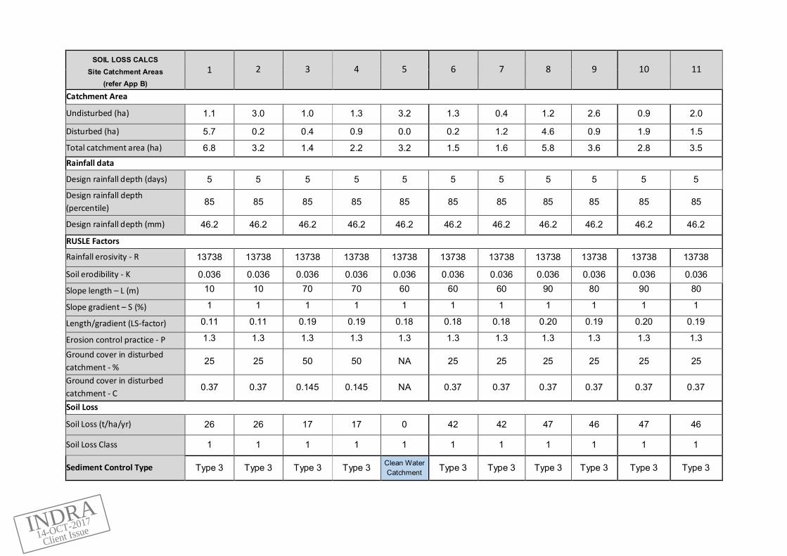
SOIL LOSS CALCSSite Catchment Areas
(refer App B)
1 2 3 4 5 6 7 8 9 10 11
Catchment Area
Undisturbed (ha) 1.1 3.0 1.0 1.3 3.2 1.3 0.4 1.2 2.6 0.9 2.0
Disturbed (ha) 5.7 0.2 0.4 0.9 0.0 0.2 1.2 4.6 0.9 1.9 1.5
Total catchment area (ha) 6.8 3.2 1.4 2.2 3.2 1.5 1.6 5.8 3.6 2.8 3.5Rainfall data
Design rainfall depth (days) 5 5 5 5 5 5 5 5 5 5 5
Design rainfall depth(percentile)
85 85 85 85 85 85 85 85 85 85 85
Design rainfall depth (mm) 46.2 46.2 46.2 46.2 46.2 46.2 46.2 46.2 46.2 46.2 46.2
RUSLE Factors
Rainfall erosivity - R 13738 13738 13738 13738 13738 13738 13738 13738 13738 13738 13738
Soil erodibility - K 0.036 0.036 0.036 0.036 0.036 0.036 0.036 0.036 0.036 0.036 0.036
Slope length – L (m) 10 10 70 70 60 60 60 90 80 90 80
Slope gradient – S (%) 1 1 1 1 1 1 1 1 1 1 1
Length/gradient (LS-factor) 0.11 0.11 0.19 0.19 0.18 0.18 0.18 0.20 0.19 0.20 0.19
Erosion control practice - P 1.3 1.3 1.3 1.3 1.3 1.3 1.3 1.3 1.3 1.3 1.3
Ground cover in disturbedcatchment - %
25 25 50 50 NA 25 25 25 25 25 25
Ground cover in disturbedcatchment - C
0.37 0.37 0.145 0.145 NA 0.37 0.37 0.37 0.37 0.37 0.37
Soil Loss
Soil Loss (t/ha/yr) 26 26 17 17 0 42 42 47 46 47 46
Soil Loss Class 1 1 1 1 1 1 1 1 1 1 1
Sediment Control Type Type 3 Type 3 Type 3 Type 3 Clean WaterCatchment Type 3 Type 3 Type 3 Type 3 Type 3 Type 3
INDRA14-OCT-2017
Client Issue

SOIL LOSS CALCSSite Catchment Areas
(refer App B)12 13 14 15 16 17 18 19 20 21 22
Catchment Area
Undisturbed (ha) 1.9 2.8 3.9 1.7 4.5 4.0 3.7 3.0 4.4 3.6 4.2
Disturbed (ha) 0.2 1.1 0.2 0.0 1.8 0.3 1.6 1.5 0.2 1.6 0.3
Total catchment area (ha) 2.1 3.9 4.1 1.7 6.2 4.4 5.3 4.5 4.6 5.2 4.5Rainfall data
Design rainfall depth (days) 5 5 5 5 5 5 5 5 5 5 5
Design rainfall depth(percentile)
85 85 85 85 85 85 85 85 85 85 85
Design rainfall depth (mm) 46.2 46.2 46.2 46.2 46.2 46.2 46.2 46.2 46.2 46.2 46.2
RUSLE Factors
Rainfall erosivity - R 13738 13738 13738 13738 13738 13738 13738 13738 13738 13738 13738
Soil erodibility - K 0.036 0.036 0.036 0.036 0.036 0.036 0.036 0.036 0.036 0.036 0.036
Slope length – L (m) 80 80 10 50 40 20 100 100 15 100 10
Slope gradient – S (%) 1 1 1 1 1 1 1 1 1 1 1
Length/gradient (LS-factor) 0.19 0.19 0.11 0.17 0.16 0.13 0.20 0.20 0.11 0.20 0.11
Erosion control practice - P 1.3 1.3 1.3 1.3 1.3 1.3 1.3 1.3 1.3 1.3 1.3Ground cover in disturbedcatchment - %
25 25 25 NA 25 25 25 25 25 25 25
Ground cover in disturbedcatchment - C
0.37 0.37 0.37 NA 0.37 0.37 0.37 0.37 0.37 0.37 0.37
Soil Loss
Soil Loss (t/ha/yr) 46 46 26 0 38 31 48 48 26 48 26
Soil Loss Class 1 1 1 1 1 1 1 1 1 1 1
Sediment Control Type Type 3 Type 3 Type 3 Clean WaterCatchment Type 3 Type 3 Type 3 Type 3 Type 3 Type 3 Type 3
INDRA14-OCT-2017
Client Issue

SOIL LOSS CALCSSite Catchment Areas
(refer App B)23 24 25 26 27 28 29 30 31 32 33
Catchment Area
Undisturbed (ha) 1.8 2.0 2.9 0.6 0.6 1.6 5.3 0.9 0.9 5.2 5.5
Disturbed (ha) 0.6 2.9 1.9 2.8 2.8 6.1 6.8 1.4 1.4 1.3 1.4
Total catchment area (ha) 2.4 4.9 4.8 3.4 3.4 7.7 12.1 2.3 2.3 6.5 6.9Rainfall data
Design rainfall depth (days) 5 5 5 5 5 5 5 5 5 5 5
Design rainfall depth(percentile)
85 85 85 85 85 85 85 85 85 85 85
Design rainfall depth (mm) 46.2 46.2 46.2 46.2 46.2 46.2 46.2 46.2 46.2 46.2 46.2
RUSLE Factors
Rainfall erosivity - R 13738 13738 13738 13738 13738 13738 13738 13738 13738 13738 13738
Soil erodibility - K 0.036 0.036 0.036 0.036 0.036 0.036 0.036 0.036 0.036 0.036 0.036
Slope length – L (m) 40 60 100 100 100 100 50 70 70 100 100
Slope gradient – S (%) 1 1 1 1 1 1 1 1 1 1 1
Length/gradient (LS-factor) 0.16 0.18 0.20 0.20 0.20 0.20 0.17 0.19 0.19 0.20 0.20
Erosion control practice - P 1.3 1.3 1.3 1.3 1.3 1.3 1.3 1.3 1.3 1.3 1.3Ground cover in disturbedcatchment - %
25 25 25 25 25 25 25 25 25 25 20
Ground cover in disturbedcatchment - C
0.37 0.37 0.37 0.37 0.37 0.37 0.37 0.37 0.37 0.37 0.44
Soil Loss
Soil Loss (t/ha/yr) 38 42 48 48 48 48 40 44 44 48 58
Soil Loss Class 1 1 1 1 1 1 1 1 1 1 1
Sediment Control Type Type 3 Type 3 Type 3 Type 3 Type 3 Type 3 Type 3 Type 3 Type 3 Type 3 Type 3
INDRA14-OCT-2017
Client Issue

SOIL LOSS CALCSSite Catchment Areas
(refer App B)34 35 36 37 38
Ops39
Security40
Flare Pad41
MOF42
SAR43
GEP
44ExternalReg Res
Catchment Area
Undisturbed (ha) 3.9 2.4 0 0 19 2.4 14 4.8 14.3 21.4 10.8
Disturbed (ha) 6.0 1.9 0.4 2.7 0 0 0 0 0 1.4 0
Total catchment area (ha) 9.8 4.3 0.4 2.7 19.0 2.4 14.0 4.8 14.3 27.0 10.8Rainfall dataDesign rainfall depth (mm) 46.2 46.2 46.2 46.2 46.2 46.2 46.2 46.2 46.2 46.2 46.2
RUSLE FactorsRainfall erosivity - R 13738 13738 13738 13738 13738 13738 13738 13738 13738 13738 13738
Soil erodibility - K 0.036 0.036 0.036 0.036 0.036 0.036 0.036 0.036 0.036 0.04 0.036
Slope length – L (m) 200 20 100 50 100 80 80 40 30 50 10
Slope gradient – S (%) 1 2 1 1 1 1 1 1 1 1 2
Length/gradient (LS-factor) 0.25 0.24 0.20 0.17 0.20 0.19 0.19 0.16 0.15 0.17 0.18
Erosion control practice - P 1.3 1.3 1.3 1.3 1.3 1.3 1.3 1.3 1.3 1.3 1.3Ground cover in disturbedcatchment - %
25 25 25 50 NA NA NA NA NA 20 NA
Ground cover in disturbedcatchment - C 0.37 0.37 0.37 0.145 NA NA NA NA NA 0.44 NA
Soil Loss
Soil Loss (t/ha/yr) 58 57 48 16 0 0 0 0 0 53 0
Soil Loss Class 1 1 1 1 1 1 1 1 1 1 1
Sediment Control Type Type 3 Type 3 Type 3 Type 3 Clean WaterCatchment
Clean WaterCatchment
Clean WaterCatchment
Clean WaterCatchment
Clean WaterCatchment
Type 3(veg buffer)
Clean WaterCatchment
INDRA14-OCT-2017
Client Issue

Client: JKC Australia LNGDoc Title: Erosion & Sediment Control Plan Wet Season 2017-18. Ichthys Onshore LNG Facilities
APPENDIX B ESC SITE DRAWINGS
INDRA14-OCT-2017
Client Issue

Revision Date Design Drawn Approved Revision Description
Tim Elder # 4399
CLIENT: EROSION & SEDIMENT CONTROL PLAN WET SEASON 2017-181 8/9/17 TE TE RH Draft for client comment2 23/9/17 TE TE RH Sent to client
NOT TO SCALE DRAWING: EZ17094-ESCP-100 REVISION: 2
REFER DRAWINGEZ17094-ESCP-101
REFER DRAWINGEZ17094-ESCP-102
REFER DRAWINGEZ17094-ESCP-103
REFER DRAWINGEZ17094-ESCP-104
REFER DRAWINGEZ17094-ESCP-105
REFER DRAWINGEZ17094-ESCP-106
LEGEND
Catchment boundary
Catchment ID
Regulating Reservoir
Clean water drainage (U-ditch/lined channel)
Clean water catchment
Stabilised exit/entry
Earth berm (covered)
Rock filter dam (Type 2/3)
Rock berm (Type 3)
Sediment fence (Type 3)
Filter bag/tube (Type 3)
2
REFER DRAWINGEZ17094-ESCP-107
REFER DRAWINGEZ17094-ESCP-107
REFER DRAWINGEZ17094-ESCP-106
INDRA14-OCT-2017
Client Issue

Revision Date Design Drawn Approved Revision Description
Tim Elder # 4399
CLIENT: EROSION & SEDIMENT CONTROL PLAN WET SEASON 2017-181 8/9/17 TE TE RH Draft for client comment2 23/9/17 TE TE RH Sent to client
NOT TO SCALE DRAWING: EZ17094-ESCP-101 REVISION: 2
1
63
5
7
28
10
4
9
44
44
44
41
TO MOF
INDRA14-OCT-2017
Client Issue

Revision Date Design Drawn Approved Revision Description
Tim Elder # 4399
CLIENT: EROSION & SEDIMENT CONTROL PLAN WET SEASON 2017-181 8/9/17 TE TE RH Draft for client comment2 23/9/17 TE TE RH Sent to client
NOT TO SCALE DRAWING: EZ17094-ESCP-102 REVISION: 2
2
11
12
13
44
44
44
8
Rock berm to be implementedas U-ditch is completed
Block in regulating reservoir to enablediversion of runoff to Mangrove basin
INDRA14-OCT-2017
Client Issue

Revision Date Design Drawn Approved Revision Description
Tim Elder # 4399
CLIENT: EROSION & SEDIMENT CONTROL PLAN WET SEASON 2017-181 8/9/17 TE TE RH Draft for client comment2 23/9/17 TE TE RH Sent to client
NOT TO SCALE DRAWING: EZ17094-ESCP-103 REVISION: 2
14
15
2
1
16
17 18
20
19
21
44
44
TO MANGROVEBASIN
INDRA14-OCT-2017
Client Issue

Revision Date Design Drawn Approved Revision Description
Tim Elder # 4399
CLIENT: EROSION & SEDIMENT CONTROL PLAN WET SEASON 2017-181 8/9/17 TE TE RH Draft for client review2 23/9/17 TE TE RH Sent to client
NOT TO SCALE DRAWING: EZ17094-ESCP-104 REVISION: 2
222
1
26
39
23
24
2728
25
Stabilise exposed surfaces with finecrushed rock/gypsum as required.
Stabilise exposed surfaces with finecrushed rock/gypsum as required.
Stabilise exposed surfaces with finecrushed rock/gypsum as required.
Stabilise exposed surfaces with finecrushed rock (or gypsum) as required.
44
44
TO FLARE PAD
40
Rumble grid
Rumble grid
Rumble grid
TOM
ANGR
OVE
BASI
N
INDRA14-OCT-2017
Client Issue

Revision Date Design Drawn Approved Revision Description
Tim Elder # 4399
CLIENT: EROSION & SEDIMENT CONTROL PLAN WET SEASON 2017-181 8/9/17 TE TE RH Draft for client comment2 23/9/17 TE TE RH Sent to client
NOT TO SCALE DRAWING: EZ17094-ESCP-105 REVISION: 2
28
31
30
29
32
28
1 Stabilise exposed surfaces withfine crushed rock/gypsum.
Stabilise exposed surfaces withfine crushed rock/gypsum.
44
44
39
Requirement for rock berm tobe assessed during wet season.
INDRA14-OCT-2017
Client Issue

Revision Date Design Drawn Approved Revision Description
Tim Elder # 4399
CLIENT: EROSION & SEDIMENT CONTROL PLAN WET SEASON 2017-181 8/9/17 TE TE RH Draft for client comment2 23/9/17 TE TE RH Sent to client
NOT TO SCALE DRAWING: EZ17094-ESCP-106 REVISION: 2
32
33
34
29
35
44
39
42
35
Stabilise exposed surfaces with fine crushedrock/gypsum as required.
Requirement for rock berm to be assessedduring wet season.
Rumble grid
INDRA14-OCT-2017
Client Issue

Revision Date Design Drawn Approved Revision Description
Tim Elder # 4399
CLIENT: EROSION & SEDIMENT CONTROL PLAN WET SEASON 2017-181 8/9/17 TE TE RH Draft for client comment2 23/9/17 TE TE RH Sent to client
NOT TO SCALE DRAWING: EZ17094-ESCP-107 REVISION: 2
36
42
38
3542
35
35
39
43GEP CORRIDOR
OPERATIONS COMPLEX
SAR
SIMOPS RD
SAR
INDRA14-OCT-2017
Client Issue

Client: JKC Australia LNGDoc Title: Erosion & Sediment Control Plan Wet Season 2017-18. Ichthys Onshore LNG Facilities
APPENDIX C TYPICAL ESC DRAWINGS
INDRA14-OCT-2017
Client Issue

Revision Date Design Drawn Approved Revision Description
Tim Elder # 4399
CLIENT: EROSION & SEDIMENT CONTROL PLAN WET SEASON 2017-18APPENDIX C: TYPICAL DESIGNS
1 8/9/17 TE TE RH Draft for client comment2 23/9/17 TE TE RH Sent to client
NOT TO SCALE DRAWING: EZ17094-ESCP-108 REVISION: 2
Figure C.2. Stabilised Crossing
Notes:∂ Design adopted from Catchments & Creeks (Version 2 –
April 2010) Construction Exits – rock pads.∂ Typical design is based on trapping sediment particles
within void space of rock.∂ Remove any sand, soil or sediment that is tracked onto
adjacent roadway following rainfall∂ Add additional 100mm layer(s) of rock when voids become
filled and/or rock pad loses effectiveness. Alternatively,replace or rip rock.
Notes:∂ Design adopted from Catchments & Creeks (Version 2 –
April 2010) Sediment Fence – sediment control technique.∂ Fabric to be at least 700mm in width and minimum unit
weight of 140GSM.∂ All fabrics to contain UV inhibitors and stabilisers to provide
a minimum of 6 mths useable construction life∂ At least 300mm of fabric must be buried in a 200mm trench
or under a continuous 100mm high layer of aggregate.∂ Both ends of fence should be turned up slope to minimise
risk of flow bypassing around the ends of the fence.∂ Wherever possible, construct sediment fence from a single
roll. To join fabric, overlap fabric to next support post.
Figure C.1. Sediment Fence
Figure C.3. Crossover – Typical Long Section
Bund – protect with geotextile(geo to extend down into U-ditch)
1:1 batter (approx.)
>0.3mAccess
CulvertU-ditch U-ditch
Crossing protected with geofabric,secured around culvert
>0.3m
U-ditch
Figure C.4. Crossover – Typical Cross Section
INDRA14-OCT-2017
Client Issue
Revision Date Design Drawn Approved Revision Description
Tim Elder # 4399
CLIENT: EROSION & SEDIMENT CONTROL PLAN WET SEASON 2017-18APPENDIX C: TYPICAL DESIGNS
1 8/9/17 TE TE RH Draft for client comment2 23/9/17 TE TE RH Sent to client
NOT TO SCALE DRAWING: EZ17094-ESCP-108 REVISION: 2
Clean rock(nominal size range 20-80mm)
0.2 mSite sheet flow
0.5 m
Figure C.6. Rock Filter Berm – Typical Cross Section
U-ditch
Earth Bund – protect with geotextile
0.3m
0.4m
Extend geotextile throughtrench (where trenchprotection is required)
Figure C.5. Earth Bund & Trench – Typical Cross Section
40mm clean rockwithin filter bags/tubes
min 1/3rd U-ditch depth
U-ditch
Figure C.8. Rock Filter Dam (Filter Bags) – Typical Cross Section
40mm clean rockwithin filter bags/tubes
min 1/3rd U-ditch depth
U-ditch
RCPs – discharge toregulating reservoir
Figure C.7. Rock Filter Dam (Filter Bags) – Typical Long Section
>0.7m
11.5
40-80mm clean rockwrapped in A19 geofabric
min 1/3rd U-ditch depth
U-ditch
RCPs – discharge toregulating reservoir
Figure C.9. Rock Filter Dam (Filter Bags) – Typical Long Section
Figure C.10. Rock Filter Dam (Reg Reservoir Block) – Typical Long Section
Concrete block with filter bags completely covering fork slots(and any other gaps). Block may need to be angled to fit.Alternative is to fully wrap block with geotextile.
U-ditch
Notes:∂ Block may need to be angled to fit∂ All gaps to be filled by filter bag/tube∂ Alternative is to wrap block in A19 geotextile,
ensuring fork slots are fully covered∂ Filter bags/geotextile to be maintained to
prevent structure being blocked withsediment.
Figure C.11. Rock Filter Dam (Concrete block)
INDRA14-OCT-2017
Client Issue

Client: JKC Australia LNGDoc Title: Erosion & Sediment Control Plan Wet Season 2017-18. Ichthys Onshore LNG FacilitiesINDRA14-OCT-2017
Client Issue


![II. DODATKOWE INFORMACJE I OBJAŚNIENIA DO ...Struk-tura: EUR Struk-tura: GBP Struk-tura: CHF Struk-tura: CZK Struk-[PLN]: [w PLN]: [w PLN]: [w PLN]: [w PLN]: [w PLN]: tura: USD EUR](https://img.pdfslide.net/doc/110x75/60e81638d589a9016c53c25d/ii-dodatkowe-informacje-i-objanienia-do-struk-tura-eur-struk-tura-gbp-struk-tura.jpg)