Embed Size (px)
Citation preview

2014-03 002.001 ENG
Head Office & Factory153, Jeongdong-ro, Seongsan-gu, Changwon-si, Gyeongsangnam-do
Tel +82 55 280 9206, 9299 Fax +82 55 210 9804
www.wiamachine.co.kr
Overseas Sales Team16F, 37, Cheoldobangmulgwan-ro, Uiwang-si, Gyeonggi-do
Tel +82 31 593 8173

L400 SeriesHYUNDAI WIA Heavy Duty CNC Turning Center

The CNC Turning Center Series, developd by Hyundai Wia, a Korean manufacturer of traditional machine tools, on the strength of its accumulated knowhow and state-of-the-art technology, is designed to maximize productivity by taking into account the need for high speed, sturdiness and accuracy.
Technical Leader
12″ 15″ Standard Long 10Station 12Station TurnMill
Spindle Bed Turret
● ● ●
● ● ●
● ● ●
● ● ●
● ● ●
● ● ●
ITEM
L400A
L400MA
L400C
L400LC
L400MC
L400LMC
Heavy-Duty, Large Work Capacity, CNC Turning Center
L400 Series● Sturdiness secured through the adoption of an all axis box guide
● All-in-one type structure with direct link for high accuracy and sturdiness
● Based on double anchor method for high accuracy pretension
● Minimized heat deformation in the main spindle
● Two-Step gear box drives the main spindle across the L400 range. (L400MA : Belt)

01 Basic FeaturesHigh Rigid Bed & Structure for Heavy Duty CNC Turning CenterL400 Series
BOX GuidewayFor the all axis of the L400 series, a guide box was utilized which demonstrates excellent feeding capabilities for medium and large equipment. In particular, as the vibration transferred through the feed shaft during heavy cutting is counteracted, highly accurate product processing is possible.
2 Step Gear Box (L400A/C/LC/MC/LMC)The 2-step gearbox offers powerful low end torque for heavy cuts as well as high speed rotation for improved surface finish.
Ball ScrewEach axis are designed with a large diameter ball-screw, fixed by double anchors on both ends to provide high rigidity and minimize thermal distortion.
04
0302
High precision, High Rigidity All in One StructureThe L400 features a 45° slant bed design which was developed using finite element analysis (FEA) to absorb vibration and minimize thermal growth, ensures a stable platform for powerful, precise cutting capabilities.
01
BMT Turret (MillTurret)Latest generation BMT top plate increases tool performance and rigidity by securing each tool with 4 screws. Overall cutting power and capability has been improved for all applications, including; milling, drilling and tapping.
Ball-screwDeviation(Diameter)
Number of Positioning Repeated (Time)
Deviation (μm)
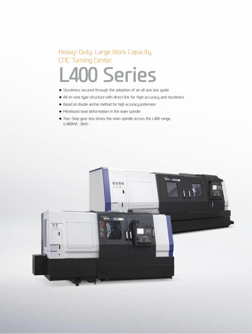
◉ Travel (X/Z) L400A | MA | C : 325/1,205mm, L400MC : 320/1,200mm, L400LC | LMC : 320/2,200mm
PowerfulCuttingCapability&WideCuttingArea04+
05
L4
00 S
ERIE
SC
NC
Tu
rN
iNg
CeN
Ter
HYu
ND
Ai W
iAM
ACH
iNe
TOO
L
Basic Features
01
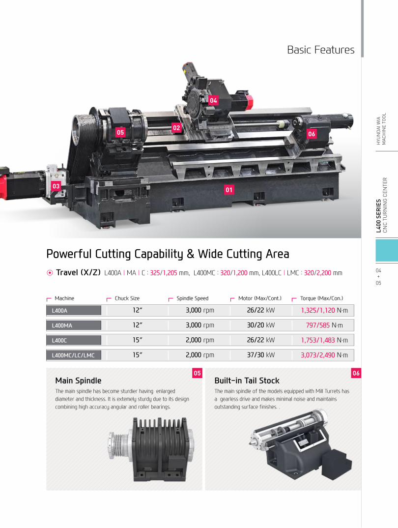
Main SpindleThe main spindle has become sturdier having enlarged diameter and thickness. It is extemely sturdy due to its design combining high accuracy angular and roller bearings.
Built-in Tail StockThe main spindle of the models equipped with Mill Turrets has a gearless drive and makes minimal noise and maintains outstanding surface finishes. .
0605
03
04
05 0602
ChuckSizeMachine SpindleSpeed Motor(Max/Cont.) Torque(Max/Con.)
12″ 3,000rpm 26/22kW 1,325/1,120N.mL400A
12″ 3,000rpm 30/20kW 797/585N.mL400MA
15″ 2,000rpm 26/22kW 1,753/1,483N.mL400C
15″ 2,000rpm 37/30kW 3,073/2,490N.mL400MC/LC/LMC

02 High-Precision SpindleLong Lasting High Accuracy & Excellent PerformanceCNC Turning CenterL400 Series
Main Spindle• The thermally symmetrical headstock has a special heat
insulation board which insulates heat from the base to maintain high accuracy during long hours of continuous operation.
• To accomplish advanced stability even during heavy duty cutting, a combination of P4 level double cylindrical roller bearings and angular bearings are configured in multiple rows.
• An advanced double locking device, separates the spindle bearing and pulley, to prevent the release of spindle bearing pretension during interrupted cutting, heavy duty cutting, chuck cylinder operation, and belt pulley tension.
C-Axis Control"M" type of L400series is attachable rotary tool and C-axis control function is adopted as standard on main spindle, When you select a optional Gearless Spindle (L400MC/LMC), you can process contouring control and various product shapes.
0.001°

Tail StockThe built-in tail stock ensures high accuracy even during heavy, powerful cutting and can be controlled automatically or manually.
❖L400A/MA/C:MT#5Built-InTailStock(Option)
L400A/MA/C
Taper : MT#4Quill Dia. : Ø100Quill Travel : 130 mm
L400LC/MC/LMC
Taper : MT#5 (Built-in)
Quill Dia. : Ø150Quill Travel : 132 mm
06+
07
L4
00 S
ERIE
SC
NC
Tu
rN
iNg
CeN
Ter
HYu
ND
Ai W
iAM
ACH
iNe
TOO
L
Spindle
Power (kW) Torque (N.m) Power (kW) Torque (N.m)
Power (kW) Torque (N.m)
Power (kW) Torque (N.m)
Power (kW) Torque (N.m)
Power (kW) Torque (N.m)
Power (kW) Torque (N.m) Power (kW) Torque (N.m)
Power (kW) Torque (N.m)
Power (kW) Torque (N.m)
Power (kW) Torque (N.m)
Power (kW) Torque (N.m)
Spindle Output/Torque DiagramContinuously variable transmission is possible due to the AC conversion motor utilized. Controlling the spindle to rotate at a certain speed is a standard function.
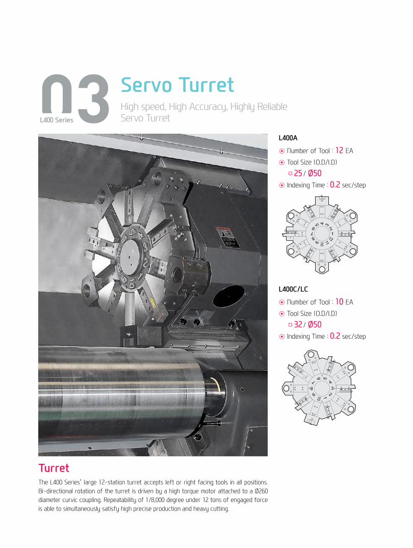
03 Servo TurretHigh speed, High Accuracy, Highly Reliable Servo Turret L400 Series
TurretThe L400 Series’ large 12-station turret accepts left or right facing tools in all positions. Bi-directional rotation of the turret is driven by a high torque motor attached to a Ø260 diameter curvic coupling. Repeatability of 1/8,000 degree under 12 tons of engaged force is able to simultaneously satisfy high precise production and heavy cutting.
◉ Number of Tool : 12EA
◉ Tool Size (O.D/I.D)
□25 / Ø50◉ Indexing Time : 0.2 sec/step
◉ Number of Tool : 10EA
◉ Tool Size (O.D/I.D)
□32 / Ø50◉ Indexing Time : 0.2 sec/step
L400A
L400C/LC
12
1011
21
4
3
8
9
67
5
12
1011
21
4
3
8
9
67
5

Power (kW) Torque (N.m) Power (kW) Torque (N.m)
Power (kW) Torque (N.m)
Power (kW) Torque (N.m)
Power (kW) Torque (N.m)
Power (kW) Torque (N.m)
08+
09
L4
00 S
ERIE
SC
NC
Tu
rN
iNg
CeN
Ter
HYu
ND
Ai W
iAM
ACH
iNe
TOO
L
Turret
Mill Tool HolderMachining capabilities have been increased with the addition of a Straight Milling Head, which can remove material from the side of the workpiece, and an Angular Milling Head, which can perform I.D. operations.
The L400 Series Mill products use BMT75P turrets as a standard as tools can be easily replaced for these turrets.
Both turrets are driven by a high torque servo motor with a 0.2 second indexing time in either direction.
◉ Number of Tool : 12EA
◉ Tool Size (O.D/I.D) : □25 / Ø50◉ Indexing Time : 0.2 sec/step
◉ Number of Tool : 12EA
◉ Tool Size (O.D/I.D) : □32 / Ø63◉ Indexing Time : 0.2 sec/step
L400MA
L400MC/LMC
Angular Milling HeadStraight Milling Head
Mill Turret (BMT)
◉ Output (Max./Cont.) : 7.5 / 5.5 kW
◉ Speed (rpm) : 4,000 r/min
◉ Collet size :Ø26 (ER40)◉ Live Tool Type : BMT75P

04 Machining CapabilityExcellent Performance, High Accuracy CuttingCNC Turning CenterL400 Series

❖ The above result might be different by types of processing circumstance
Machining Variation
Sample Workpiece
L400MA
10+
11
L4
00 S
ERIE
SC
NC
Tu
rN
iNg
CeN
Ter
HYu
ND
Ai W
iAM
ACH
iNe
TOO
L
Machining
Drilling
ToolDia.SpindlespeedCuttingdepthForwardingspeed(Rev.)CuttingspeedChipdischarge
Ø40214 r/min80 mm0.36 mm/rev27 m/min774 cc/min
〈Material〈JIS〉:S45C(Carbon steel〉
End Milling〈Material〈JIS〉:S45C(Carbon steel〉
ToolspeedCuttingspeedForwardingspeed(Min.)Forwardingspeed(Feed)CuttingdepthChipdischarge
1000 r/min63 m/min200 mm/min0.1 mm/f4.0 mm16 cc/min
Tapping〈Material〈JIS〉:S45C(Carbon steel〉
TapsizeToolspeedCuttingspeedForwardingspeed(Min.)Forwardingspeed(Rev.)Cuttingdepth
M20×2.5127r/min8m/min317mm/min2.5mm/rev30mm
Drilling〈Material〈JIS〉:S45C(Carbon steel〉
ToolspeedCuttingspeedForwardingspeed(Min.)Forwardingspeed(Rev.)CuttingdepthChipdischarge
390 r/min27 m/min117mm/min0.3mm/rev40mm44cc/min
OD Cutting〈Material〈JIS〉:S45C(Carbon steel〉
WorkpieceSpindlespeedCuttingdepthForwardingspeed(Rev.)CuttingspeedChipdischarge
Ø276284 r/min8 mm0.45 mm/rev232 m/min835 cc/min
O.D Cutting
Face Milling
Drilling
End Milling
I.D Cutting
O.D Hole Drilling
I.D Threading
Ball-End Milling

Machine Monitoring
Energy SavingIntelligent Machining
Easy Programming
HW-MMS HW
-ESS
HW-DPRO T/TM
User Friendly
HW-TM
HYUNDAI WIA Smart System for CNC Turning Center
User Convenience
HW-eDNC
HW-MCG
HW-PGi F (HYUNDAIWIAProgrammingGuideiforFanucSystem)(StandardwhenapplyingFANUC32i)
Realistic 3D solid animationProgramming simulation
Example of easy programmingEasy programming interactively
without code
Engraving CycleProgramming with only entering text by
controlling C-axis
05 Smart SystemSoftware for Smart Operating and MachiningL400 Series

Faster processing programming and enhanced processing accuracy are possible through HYUNDAI WIA Smart System. It also maximizes productivity through equipment monitoring and environment-friendly software.
HYUNDAI WIA Smart System
HW-TMHYUNDAIWIAToolMonitoring
This is an equipment-monitoring software which checks the overload, attrition and possible damage of equipment by analyzing the spindles and the output load of the feed shaft generated during a processing operation.
HW-DPRO T/TMHYUNDAIWIADialoguePROgramTurn/TurnMill
Using a dialogue method, this software makes it easy to work out a program for a lathe processing operation with complicated configurations. (Can be installed on a PC.)
HW-MMSHYUNDAIWIAMachineMonitoringSystem
This software is for remote control monitoring of equipment status (mobile, PC.) It checks and manages the state of multiple pieces of equipment and the progress of processing on a real time basis.
HW-ESSHYUNDAIWIAEnergySavingSystem
This is an environment-friendly power reduction software reducing the standby power unnecessarily wasted in the equipment waiting for a processing operation.
HW-eDNCHYUNDAIWIAethernetDirectNumericalControl
This software transmits and receives the CNC of processing equipment, the processing program and the NC data on a PC through the internet or serial communications, while managing the processing program of the CNC memory.
HW-MCGHYUNDAIWIAMachineGuidance
NC loading type software offering user-convenience functions like operating equipment, maintenance and monitoring of managing equipment
USB Port (OnlyHYUNDAIWIAFANUCiSeries)Convenience is increased when inputting and outputting program. Because it is now capable of using USB port in addition to current way like CF memory card or LAN
12+
13
L4
00 S
ERIE
SC
NC
Tu
rN
iNg
CeN
Ter
HYu
ND
Ai W
iAM
ACH
iNe
TOO
L

06 User ConvenienceVarious Devices for User Friendly
L400 Series
Steady Rest Auto Q-Setter
Chuck Type Tail Stock
For long parts, such as shafts, the optional steady-rest increases rigidity and minimizes vibration.
When applying programmable hyd. steady rest as an option, machining ability will increase allowing you to adjust the position of steady rest according to the shape of work by using a fixed pin that is connected to the turret.
When machining boring material like pipe which is not able to use tail stock, stable product-machining can be possible when using a chuck type tail stock.
Cutting tools are calibrated quickly and accurately with the addition of a q-setter.
Each tool tip is turned off automatically by program that inputs the position automatically.
Chuck Size : 10″Spindle Speed : 3,000rpm
Quill Dia. : Ø75
L400A L400MA L400C(LC) L400MC(LMC) ● ● ● ● ○ ○ ○ ○ ○ ○ ○ ○ ○ ○ ○ ○ ○ ○ ○ ○ ○ ○ ○ ○ ○ ○ ○ ○ ○ ○ ○ ○ ○ ○ ○ ○ ○ ○ ○ ○ ○ ○ ○ ○ ○ ○ ○ ○ ○ ○ ○ ○ ☆ ☆ ☆ ☆ ○ - - - - - ○ (-) - - ○ - (○) - - - - ○ ○ ○ ○ ○ - - - - ● ● ● ● ☆ ☆ ☆ ☆ ☆ ☆ ☆ ☆ ☆ ☆ ☆ ☆ ○ ○ ○ ○ - - - - ☆ ☆ ☆ ☆ ○ ○ ○ ○ ○ ○ ○ ○ ○ ○ ○ ○ ○ ○ ○ ○ ☆ ☆ ☆ ☆ ○ ○ ○ ○ - - - - ☆ ☆ ☆ ☆ - - - - - - - - ○ ○ ○ ○ ☆ ☆ ☆ ☆ ○ ○ ○ ○ ○ ○ ○ ○ - - - - ☆ ☆ ☆ ☆ ● ● ● ● - - - - ● ● ● ● ☆ ☆ ☆ ☆ ○ ○ ○ ○ ○ ○ ○ ○ ○ ○ ○ ○ ○ ○ ○ ○ ☆ ☆ ☆ ☆ ● ● ● ● ☆ ☆ ☆ ☆ ☆ ☆ ☆ ☆
Call LightCall LightCall Light & BuzzerElectric Cabinet LightRemote MPGSpindle Load meterSpindle Speed meterWorkcounterTotalcounterToolcounter
Multi-Toolcounter
Electric Circuit BreakerAVR(Auto Voltage Regulator)
Transformer
Auto Power OffMeasurementQ-SetterAutomatic Q-SetterWork Close Confirmation Device(Only for Special Chuck)Work Setter
Linear Scale
Coolant Level Sensor (Only for Chip Conveyor)EnvironmentAir ConditionerDehumidifierOil Mist CollectorOil Skimmer (Only for Chip Conveyor)MQL (Minimal Quantity Lubrication)Fixture & AutomationAuto DoorAuto Shutter (Only for Automatic System)Sub Operation PannelBar Feeder InterfaceBar Feeder (FEDEK)Extra M-Code 4eaAutomation Interface
I/O Extension (IN & OUT)
Parts CatcherTurret Work Pusher (For Automation)Hyd. DeviceStandard Hyd. Cylinder
Standard Hyd. Unit
S/WMachine Guidance (HW-MCG : FANUC)Tool Monitoring (HW-TM : FANUC)DNC Software (HW-eDNC : FANUC)Interactive ProgrammingEnergy Saving System (HW-ESS : FANUC)Machine Monitoring System (HW-MMS : FANUC)ETCTool BoxCustomized ColorCAD & CAM
1Color : ■3Color : ■■■3Color : ■■■B
LED TypeLED TypeDigitalDigitalDigital6EA9EA
35kVA40kVA50kVA60kVA
TACOSMC
X AxisZ Axis
High Speed
16Contact32ContactMain SP.
Hollow60bar/13ℓ60bar/20ℓ
Need Munsel No.
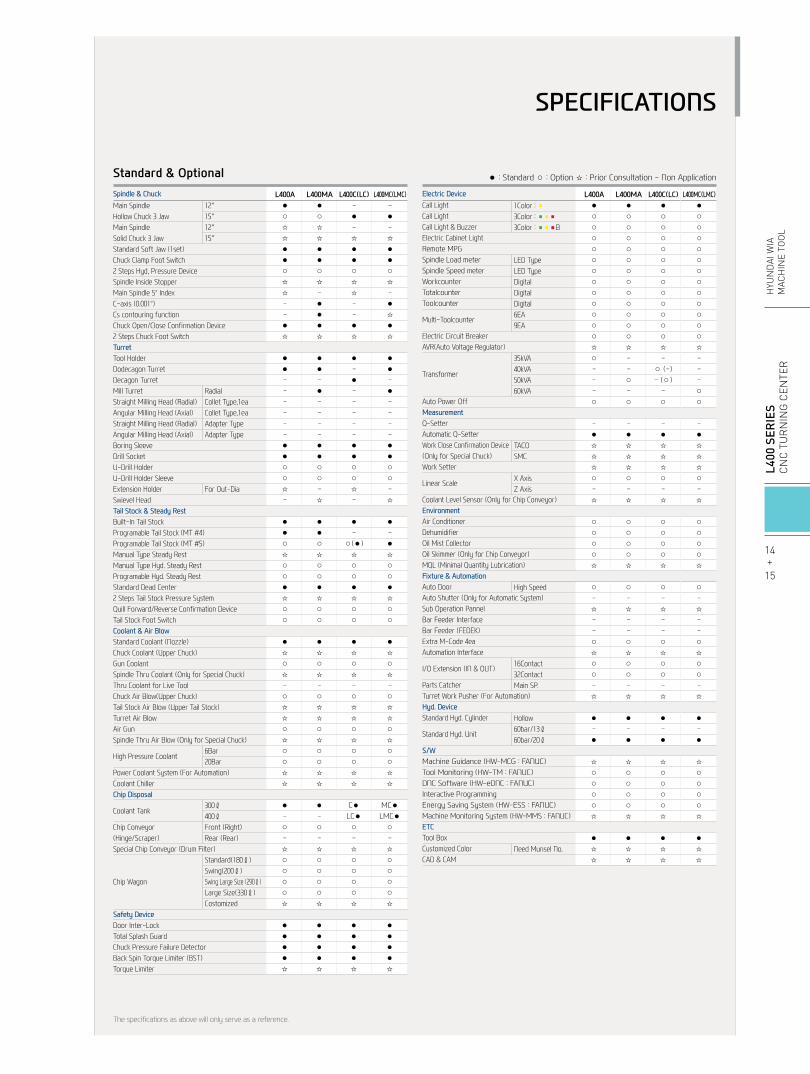
Standard & Optional
Main SpindleHollow Chuck 3 JawMain SpindleSolid Chuck 3 JawStandard Soft Jaw (1set)Chuck Clamp Foot Switch2 Steps Hyd, Pressure DeviceSpindle Inside StopperMain Spindle 5° IndexC-axis (0.001°)Cs contouring functionChuck Open/Close Confirmation Device2 Steps Chuck Foot SwitchTurretTool HolderDodecagon TurretDecagon TurretMill TurretStraight Milling Head (Radial)Angular Milling Head (Axial)Straight Milling Head (Radial)Angular Milling Head (Axial)Boring SleeveDrill SocketU-Drill HolderU-Drill Holder SleeveExtension HolderSwievel HeadTail Stock & Steady RestBuilt-In Tail StockProgramable Tail Stock (MT #4)Programable Tail Stock (MT #5)Manual Type Steady RestManual Type Hyd. Steady RestProgramable Hyd. Steady RestStandard Dead Center2 Steps Tail Stock Pressure SystemQuill Forward/Reverse Confirmation DeviceTail Stock Foot SwitchCoolant & Air BlowStandard Coolant (Nozzle)Chuck Coolant (Upper Chuck)Gun CoolantSpindle Thru Coolant (Only for Special Chuck)Thru Coolant for Live ToolChuck Air Blow(Upper Chuck)Tail Stock Air Blow (Upper Tail Stock)Turret Air BlowAir GunSpindle Thru Air Blow (Only for Special Chuck)
High Pressure Coolant
Power Coolant System (For Automation)Coolant ChillerChip Disposal
Coolant Tank
Chip Conveyor(Hinge/Scraper)Special Chip Conveyor (Drum Filter)
Chip Wagon
Safety DeviceDoor Inter-LockTotal Splash GuardChuck Pressure Failure DetectorBack Spin Torque Limiter (BST)Torque Limiter
12″15″12″15″
RadialCollet Type,1eaCollet Type,1eaAdapter TypeAdapter Type
For Out-Dia
6Bar20Bar
300ℓ400ℓFront (Right)Rear (Rear)
Standard(180ℓ)Swing(200ℓ)Swing Large Size (290ℓ)Large Size(330ℓ)Costomized
Spindle & Chuck Electric Device
● : Standard ○ : Option ☆ : Prior Consultation - Non Application
L400A L400MA L400C(LC) L400MC(LMC) ● ● - - ○ ○ ● ● ☆ ☆ - - ☆ ☆ ☆ ☆ ● ● ● ● ● ● ● ● ○ ○ ○ ○ ☆ ☆ ☆ ☆ ☆ - ☆ - - ● - ● - ● - ☆ ● ● ● ● ☆ ☆ ☆ ☆ ● ● ● ● ● ● - ● - - ● - - ● - ● - - - - - - - - - - - - - - - - ● ● ● ● ● ● ● ● ○ ○ ○ ○ ○ ○ ○ ○ ☆ - ☆ - - ☆ - ☆ ● ● ● ● ● ● - - ○ ○ ○(●) ● ☆ ☆ ☆ ☆ ○ ○ ○ ○ ○ ○ ○ ○ ● ● ● ● ☆ ☆ ☆ ☆ ○ ○ ○ ○ ○ ○ ○ ○ ● ● ● ● ☆ ☆ ☆ ☆ ○ ○ ○ ○ ☆ ☆ ☆ ☆ - - - - ○ ○ ○ ○ ☆ ☆ ☆ ☆ ☆ ☆ ☆ ☆ ○ ○ ○ ○ ☆ ☆ ☆ ☆ ○ ○ ○ ○ ○ ○ ○ ○ ☆ ☆ ☆ ☆ ☆ ☆ ☆ ☆ ● ● C● MC● - - LC● LMC● ○ ○ ○ ○ - - - - ☆ ☆ ☆ ☆ ○ ○ ○ ○ ○ ○ ○ ○ ○ ○ ○ ○ ○ ○ ○ ○ ☆ ☆ ☆ ☆
● ● ● ● ● ● ● ● ● ● ● ● ● ● ● ● ☆ ☆ ☆ ☆
The specifications as above will only serve as a reference.
14+
15
L4
00 S
ERIE
SC
NC
Tu
rN
iNg
CeN
Ter
HYu
ND
Ai W
iAM
ACH
iNe
TOO
L
SPECIFICATIONS

unit : mm(in)External Dimensions
L400A/MA/C/MC (SLUB5 Steady Rest Application)
SPECIFICATIONS
214
(8.4
)
470
(18.
5)35
9(15
.6)
2147
(84.
5)
1040 (40.9)
762 (30)
590(23.2)515(20.3)
2244(88.3)2319(91.3)
822
(32.
3)
400(15.7)
214
(8.4
)
720(28.3)(Auto Door)
(Auto Door Left) (Auto Door Right)
1124
(44.
2)
395(
15.6
)47
0(18
.5)
980 (38.6)
702 (27.6)
525 (20.6)2282 (89.8)
450 (17.7)2207 (86.9)
400(15.7)
792(
31.2
)
2035
(80.
1)21
10 (8
3)
: Expand Type Coolant Tank

unit : mm(in)External Dimensions
L400LC/LMC (SLUB5 Steady Rest Application)
16+
17
L4
00 S
ERIE
SC
NC
Tu
rN
iNg
CeN
Ter
HYu
ND
Ai W
iAM
ACH
iNe
TOO
L
SPECIFICATIONS
214
(8.4
)
470
(18.
5)35
9(15
.6)
2147
(84.
5)
1040 (40.9)
762 (30)
590(23.2)515(20.3)
2244(88.3)2319(91.3)
822
(32.
3)
400(15.7)
214
(8.4
)
720(28.3)(Auto Door)
(Auto Door Left) (Auto Door Right)
1124
(44.
2)
395(
15.6
)47
0(18
.5)
980 (38.6)
702 (27.6)
525 (20.6)2282 (89.8)
450 (17.7)2207 (86.9)
400(15.7)
792(
31.2
)
2035
(80.
1)21
10 (8
3)
: Expand Type Coolant Tank
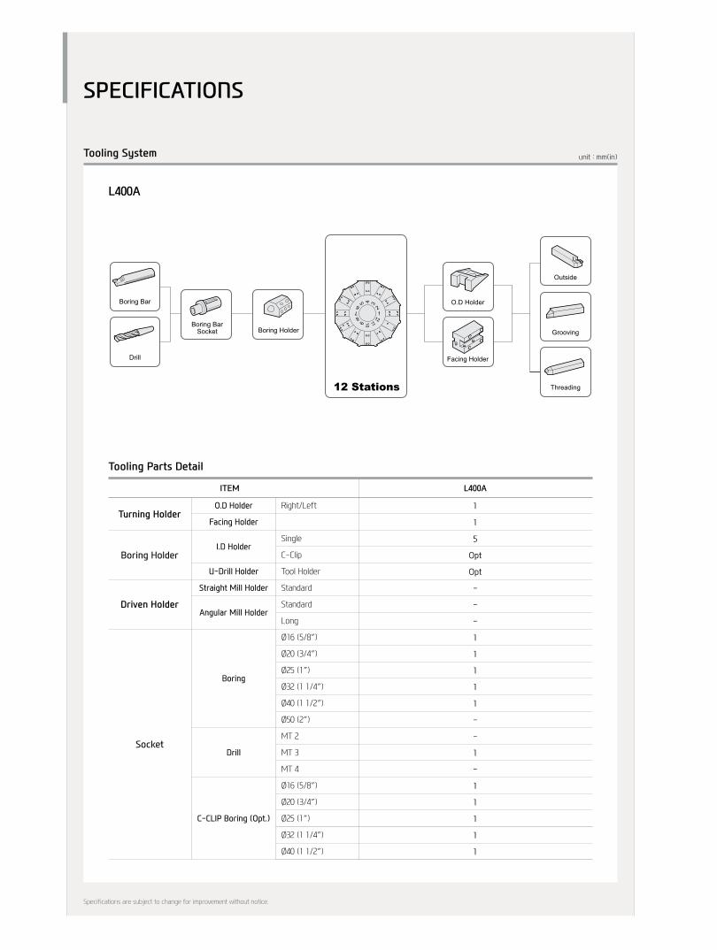
unit : mm(in)Tooling System
SPECIFICATIONS
BMT 75P12 Stations
10 Stations
StraightMill Holder
O.D Holder
Boring Holder
Boring Holder
O.D Holder
Facing Holder
Milling Collet
Outside
Grooving
Threading
Boring BarSocket
Boring Bar
Drill
12 Stations
Boring Holder
O.D Holder
Facing Holder
Outside
Grooving
Threading
Boring BarSocket
Boring Bar
Drill
Tap
End Mill
Center Drill
Drill
Reamer
Facing Holder
O.D Tool
Boring Bar
Drill
U-Drill
AngularMill Holder
Plug
Boring BarSocket
Right/Left
Single
C-Clip
Tool Holder
Standard
Standard
Long
Ø16 (5/8″)
Ø20 (3/4″)
Ø25 (1″)
Ø32 (1 1/4″)
Ø40 (1 1/2″)
Ø50 (2″)
MT 2
MT 3
MT 4
Ø16 (5/8″)
Ø20 (3/4″)
Ø25 (1″)
Ø32 (1 1/4″)
Ø40 (1 1/2″)
O.D Holder
Facing Holder
I.D Holder
U-Drill Holder
Straight Mill Holder
Angular Mill Holder
Boring
Drill
C-CLIP Boring (Opt.)
Turning Holder
Driven Holder
Boring Holder
Socket
ITEM L400A
1
1
5
Opt
Opt
-
-
-
1
1
1
1
1
-
-
1
-
1
1
1
1
1
Tooling Parts Detail
Specifications are subject to change for improvement without notice.
L400A

unit : mm(in)Tooling System
18+
19
L4
00 S
ERIE
SC
NC
Tu
rN
iNg
CeN
Ter
HYu
ND
Ai W
iAM
ACH
iNe
TOO
L
SPECIFICATIONS
BMT 75P12 Stations
10 Stations
StraightMill Holder
O.D Holder
Boring Holder
Boring Holder
O.D Holder
Facing Holder
Milling Collet
Outside
Grooving
Threading
Boring BarSocket
Boring Bar
Drill
12 Stations
Boring Holder
O.D Holder
Facing Holder
Outside
Grooving
Threading
Boring BarSocket
Boring Bar
Drill
Tap
End Mill
Center Drill
Drill
Reamer
Facing Holder
O.D Tool
Boring Bar
Drill
U-Drill
AngularMill Holder
Plug
Boring BarSocket
Right/Left
Single
C-Clip
Tool Holder
Standard
Standard
Long
Ø16 (5/8″)
Ø20 (3/4″)
Ø25 (1″)
Ø32 (1 1/4″)
Ø40 (1 1/2″)
Ø50 (2″)
MT 2
MT 3
MT 4
Ø16 (5/8″)
Ø20 (3/4″)
Ø25 (1″)
Ø32 (1 1/4″)
Ø40 (1 1/2″)
O.D Holder
Facing Holder
I.D Holder
U-Drill Holder
Straight Mill Holder
Angular Mill Holder
Boring
Drill
C-CLIP Boring (Opt.)
Turning Holder
Driven Holder
Boring Holder
Socket
ITEM L400C/LC
1
1
4
Opt
Opt
-
-
-
1
1
1
1
1
-
-
1
-
1
1
1
1
1
Tooling Parts Detail
Specifications are subject to change for improvement without notice.
L400C/LC

unit : mm(in)Tooling System
BMT 75P12 Stations
10 Stations
StraightMill Holder
O.D Holder
Boring Holder
Boring Holder
O.D Holder
Facing Holder
Milling Collet
Outside
Grooving
Threading
Boring BarSocket
Boring Bar
Drill
12 Stations
Boring Holder
O.D Holder
Facing Holder
Outside
Grooving
Threading
Boring BarSocket
Boring Bar
Drill
Tap
End Mill
Center Drill
Drill
Reamer
Facing Holder
O.D Tool
Boring Bar
Drill
U-Drill
AngularMill Holder
Plug
Boring BarSocket
Right/Left
Single
C-Clip
Tool Holder
Standard
Standard
Long
Ø16 (5/8″)
Ø20 (3/4″)
Ø25 (1″)
Ø32 (1 1/4″)
Ø40 (1 1/2″)
Ø50 (2″)
MT 2
MT 3
MT 4
O.D Holder
Facing Holder
I.D Holder
U-Drill Holder
Straight Mill Holder
Angular Mill Holder
Boring
Drill
Turning Holder
Driven Holder
Boring Holder
Socket
ITEM L400MA L400MC L400LMC
2 2 2
2 2 2
4 4 4
- Opt Opt
Opt Opt Opt
1 1 1
1 1 1
- - -
1 - -
1 1 1
1 1 1
1 1 1
1 1 1
- 1 1
Opt - -
1 1 1
Opt Opt Opt
Tooling Parts Detail
Specifications are subject to change for improvement without notice.
L400MA/MC/LMC
SPECIFICATIONS

unit : mm(in)Interference
20+
21
L4
00 S
ERIE
SC
NC
Tu
rN
iNg
CeN
Ter
HYu
ND
Ai W
iAM
ACH
iNe
TOO
L
SPECIFICATIONS
12
1011
21
43
8
9 67
5
170(6.7)40(1.5)
ø63(ø2.5)
113(4.4)
ø63(ø2.5)ø300.2(ø11.8)
210 (8.3)
ø570
(ø22
.4) -
Max. tu
rning
dia.
660 (25.9)325 (12.8)X-Stroke
285(11.2)
35 (1.4)
335 (13.2)
125(4.9)210 (8.3) 40 (1.6)
620 (24.4)
ø272
.6(ø
10.7)
ø260.3(ø10.2)
80(3.1)(MAX:)
80(3.1)
90(3.5)
110(4.3)
47.5(1.8)
45(1.7)
40(1.5)
ø741.7(ø29.2)
ø320(ø12.6)
Ø558(ø 22)
ø577(ø22.7)
615 (24.2)
37 (1.5)60 (2.4)
260 (10.2)
357 (14) 300 (11.8)
260 (10.2) 315 (12.4) 10 (0.4)40 (1.6)
32 (1
.3)
ø 694 (ø 27.3)
ø 38
1 (ø
15)
ø 50
(ø 1.97)
32(1.3)
ø 714 (28.1)
ø 326
(ø12.8)
ø 730(ø28.7)
ø 630
(ø24
.8) - M
ax. tu
rning
dia.
80(3
.1)
32 (1
.3)
105(4.1)
325 (12.8)X-Stroke
615 (24.2)
95 (3.7)355 (14) 295 (11.6) 325 (12.8)
X-Stroke
260 (10.2) 260 (10.2) 320 (12.6) 5 (0.2)
35 (1.4)
25 (1
)
80 (3.1
)
25 (1) ø 610 (ø 24)
ø 50(ø 1.97)
ø 270
(ø 10.6)
ø 714.63(ø 28.1)
ø 582
(ø 22.9)
ø 640 (ø25.2) - Max. turning dia.
60 (2.4)37 (1.5)
ø 305(ø 12)L400A
L400C/LC
L400MA/MC/LMC

unit : mm(in)Interference
SPECIFICATIONS
Straight Milling Head
OD Turning Holder
Boring Bar Holder
OD Turning Holder
Boring Bar Holder
OD Turning Holder
Boring Bar Holder Angular Milling Head
50(2)
2(0.1)
620(
24.4
)62
0(24
.4)
620(
24.4
)62
0(24
.4)
ø304
(12)
[ø38
1(15
)]ø3
04(1
2)[ø
381(
15)]
325(
12.8
)(X-A
XIS
TRAV
EL)
[320
(12.
6)]
325(
12.8
)(X-A
XIS
TRAV
EL)
[320
(12.
6)]
325(
12.8
)(X-A
XIS
TRAV
EL)
[320
(12.
6)]
320(
12.6
)[2
90(1
1.4)
]31
5(12
.4)
300(
11.8
)
40 (1.5
)99
.3(3
.9)
160.
7(6
.3)
10(0
.4)
[310
(12.
2)]
325(
12.8
)(X-A
XIS
TRAV
EL)
[320
(12.
6)]
315(
12.4
)10 (0.4
)30
5(12
)
65 (2.5
)95 (3.7
)
55 (2.1
)
210(
8.3)
[310
(12.
2)]
300(
11.8
)32
0(12
.6)
110
(4.3
)21
0(8
.3)
25 (1)
[295
(11.
6)]
285(
11.2
)33
5 210(
8.3)
90 (3.5
)35 (1.4
)
40 (1.6
)[2
80(1
1)]
[61(2.4)]92.5(3.6)[64(2.5)] 1,205(47.4) (Z-AXIS TRAVEL)
1,205(47.4)2t(0.1) 48(1.9)
113(4.4)
7(0.3) (Z-AXIS TRAVEL)
31.5(1.2)
7(0.3)
5(0.2)
5(0.2)
5(0.2)
5(0.2)
137.5(5.4)
27.7(1.1)
139.3(5.5)1,100(43.3) TAIL STOCK TRAVEL130(5.1) SLEEVE TRAVEL
[2,100(82.7)]
1,100(43.3) TAIL STOCK TRAVEL[2,100(82.7)]
[150(5.9)][150(5.9)]
232.7(9.2)
51(2)59.7(2.3)
51(2)[70(2.7)]
59.7(2.3)
122(4.8)29.5(1.2)
[149(5.8)]
122(4.8)[149(5.8)]
[219(8.6)][177(7)]
130(5.1) SLEEVE TRAVEL[150(5.9)][150(5.9)]
232.7(9.2)[219(8.6)][177(7)]
[161(6.3)][161(6.3)]
139.3(5.5)[161(6.3)][161(6.3)]
139.3(5.5)[161(6.3)][161(6.3)]
110(4.3)
110(4.3)
160(6.3)
[2,200(86.6)]
1,205(47.4) (Z-AXIS TRAVEL)
(Z-AXIS TRAVEL)
[2,200(86.6)]
2(0.1)
2(0.1)
50(2)[61(2.4)] 124(4.8)
[104(4.1)]
110(4.3)
1,205(47.4)[2,200(86.6)]
92(3.6)8(0.3)
[129(5)]
61(2.4)2
(0.1)50(2)
[61(2.4)] 124(4.8)[159(6.2)]
14(0.5)
23.7(0.9)
27.7(1.1)
18.7(0.7)
ø304
(12)
[ø38
1(15
)]
130(5.1) SLEEVE TRAVEL[150(5.9)][150(5.9)]
232.7(9.2)
51(2)59.7(2.3)122(4.8)
57(2.2)
[149(5.8)][219(8.6)][177(7)]
1,100(43.3) TAIL STOCK TRAVEL[2,100(82.7)]
139.3(5.5)[161(6.3)][161(6.3)]
130(5.1) SLEEVE TRAVEL[150(5.9)][150(5.9)]
219.7(8.6)
149(5.8)
70(2.7)0.7
[177(7)]1,100(43.3) TAIL STOCK TRAVEL[2,100(82.7)]
139.3(5.5)[161(6.3)]
130(5.1)[150(5.9)][150(5.9)]
219.7(8.6)
149(5.8)70(2.7)
0.754(2.1) [70(2.7)]
[177(7)]1,100(43.3) TAIL STOCK TRAVEL[2,100(82.7)]
2(0.1)
2(0.1)
110(4.3)
100(3.9)
1,205(47.4) (Z-AXIS TRAVEL)[2,200(86.6)]
50(2)[61(2.4)] 124(4.8)
34(1.3)
[104(4.1)]
1,100(43.3) TAIL STOCK TRAVEL[2,100(82.7)]
51(2)0.5 [70(2.7)]
59.7(2.3)122(4.8)[149(5.8)] 130(5.1) SLEEVE TRAVEL
[150(5.9)][150(5.9)]
232.7(9.2)[219(8.6)][177(7)]
139.3(5.5)[161(6.3)][161(6.3)]
ø304
(12)
[ø38
1(15
)]
325(
12.8
)(X-A
XIS
TRAV
EL)
[320
(12.
6)]
320(
12.6
)5
(0.2
)30
0(11
.8)
210(
8.2)
90 (3.5
)[2
95(1
1.6)
]
325(
12.8
)(X-A
XIS
TRAV
EL)
304(
12)
304(
12)
615(
24.2
)61
5(24
.2)
615(
24.2
)61
5(24
.2)
381(
15)
381(
15)
130(5.1) SLEEVE TRAVEL[150(5.9)]
232.7(9.2)[177(7)]
59.7(2.3)9(0.3)
122(4.8)51(2)
139.3(5.5)
107(4.2)
37.7(1.5)
1,100(43.3) TAIL STOCK TRAVEL
[161(6.3)]
130(5.1) SLEEVE TRAVEL[150(5.9)]
232.7(9.2)[177(7)]
59.7(2.3)
7(0.2)
122(4.8)51(2)
139.3(5.5)
37.7(1.5)
108(4.2)
44.7(1.7)
44.7(1.7)
1,100(43.3) TAIL STOCK TRAVEL
[161(6.3)]
35(1
.4) 5(0.2)
5(0.
2)32
0(12
.6)
295(
11.6
)
73.4
(2.9
)18
6.6
97.3
)
100(3.9)
1,205(47.4)
15(0.6)
2t(0.1) 48(1.9)
120(4.7)
(Z-AXIS TRAVEL) 100(3.9)
100(3.9)
(Z-AXIS TRAVEL)1,205(47.4)61(2.4) [2,200(86.6)]
[137(55.4)] 100(3.9)
100(3.9)
325(
12.8
)(X-A
XIS
TRAV
EL)
295(
11.6
)30 (1.1
)32
0(12
.6)
60(2
.3)
260(
10.2
)
5(0.2)
5(0.2)
150(5.9)
295(
11.6
)30 (1.2
)
325(
12.8
)(X-A
XIS
TRAV
EL)
[320
(12.
6)]
60(2
.3)
260(
10.2
)
150(5.9)
2(0.1)
L400A (■: MT#5)

unit : mm(in)Tooling Travel Range
22+
23
L4
00 S
ERIE
SC
NC
Tu
rN
iNg
CeN
Ter
HYu
ND
Ai W
iAM
ACH
iNe
TOO
L
SPECIFICATIONS
Straight Milling Head
OD Turning Holder
Boring Bar Holder
OD Turning Holder
Boring Bar Holder
OD Turning Holder
Boring Bar Holder Angular Milling Head
50(2)
2(0.1)
620(
24.4
)62
0(24
.4)
620(
24.4
)62
0(24
.4)
ø304
(12)
[ø38
1(15
)]ø3
04(1
2)[ø
381(
15)]
325(
12.8
)(X-A
XIS
TRAV
EL)
[320
(12.
6)]
325(
12.8
)(X-A
XIS
TRAV
EL)
[320
(12.
6)]
325(
12.8
)(X-A
XIS
TRAV
EL)
[320
(12.
6)]
320(
12.6
)[2
90(1
1.4)
]31
5(12
.4)
300(
11.8
)
40 (1.5
)99
.3(3
.9)
160.
7(6
.3)
10(0
.4)
[310
(12.
2)]
325(
12.8
)(X-A
XIS
TRAV
EL)
[320
(12.
6)]
315(
12.4
)10 (0.4
)30
5(12
)
65 (2.5
)95 (3.7
)
55 (2.1
)
210(
8.3)
[310
(12.
2)]
300(
11.8
)32
0(12
.6)
110
(4.3
)21
0(8
.3)
25 (1)
[295
(11.
6)]
285(
11.2
)33
5 210(
8.3)
90 (3.5
)35 (1.4
)
40 (1.6
)[2
80(1
1)]
[61(2.4)]92.5(3.6)[64(2.5)] 1,205(47.4) (Z-AXIS TRAVEL)
1,205(47.4)2t(0.1) 48(1.9)
113(4.4)
7(0.3) (Z-AXIS TRAVEL)
31.5(1.2)
7(0.3)
5(0.2)
5(0.2)
5(0.2)
5(0.2)
137.5(5.4)
27.7(1.1)
139.3(5.5)1,100(43.3) TAIL STOCK TRAVEL130(5.1) SLEEVE TRAVEL
[2,100(82.7)]
1,100(43.3) TAIL STOCK TRAVEL[2,100(82.7)]
[150(5.9)][150(5.9)]
232.7(9.2)
51(2)59.7(2.3)
51(2)[70(2.7)]
59.7(2.3)
122(4.8)29.5(1.2)
[149(5.8)]
122(4.8)[149(5.8)]
[219(8.6)][177(7)]
130(5.1) SLEEVE TRAVEL[150(5.9)][150(5.9)]
232.7(9.2)[219(8.6)][177(7)]
[161(6.3)][161(6.3)]
139.3(5.5)[161(6.3)][161(6.3)]
139.3(5.5)[161(6.3)][161(6.3)]
110(4.3)
110(4.3)
160(6.3)
[2,200(86.6)]
1,205(47.4) (Z-AXIS TRAVEL)
(Z-AXIS TRAVEL)
[2,200(86.6)]
2(0.1)
2(0.1)
50(2)[61(2.4)] 124(4.8)
[104(4.1)]
110(4.3)
1,205(47.4)[2,200(86.6)]
92(3.6)8(0.3)
[129(5)]
61(2.4)2
(0.1)50(2)
[61(2.4)] 124(4.8)[159(6.2)]
14(0.5)
23.7(0.9)
27.7(1.1)
18.7(0.7)
ø304
(12)
[ø38
1(15
)]
130(5.1) SLEEVE TRAVEL[150(5.9)][150(5.9)]
232.7(9.2)
51(2)59.7(2.3)122(4.8)
57(2.2)
[149(5.8)][219(8.6)][177(7)]
1,100(43.3) TAIL STOCK TRAVEL[2,100(82.7)]
139.3(5.5)[161(6.3)][161(6.3)]
130(5.1) SLEEVE TRAVEL[150(5.9)][150(5.9)]
219.7(8.6)
149(5.8)
70(2.7)0.7
[177(7)]1,100(43.3) TAIL STOCK TRAVEL[2,100(82.7)]
139.3(5.5)[161(6.3)]
130(5.1)[150(5.9)][150(5.9)]
219.7(8.6)
149(5.8)70(2.7)
0.754(2.1) [70(2.7)]
[177(7)]1,100(43.3) TAIL STOCK TRAVEL[2,100(82.7)]
2(0.1)
2(0.1)
110(4.3)
100(3.9)
1,205(47.4) (Z-AXIS TRAVEL)[2,200(86.6)]
50(2)[61(2.4)] 124(4.8)
34(1.3)
[104(4.1)]
1,100(43.3) TAIL STOCK TRAVEL[2,100(82.7)]
51(2)0.5 [70(2.7)]
59.7(2.3)122(4.8)[149(5.8)] 130(5.1) SLEEVE TRAVEL
[150(5.9)][150(5.9)]
232.7(9.2)[219(8.6)][177(7)]
139.3(5.5)[161(6.3)][161(6.3)]
ø304
(12)
[ø38
1(15
)]
325(
12.8
)(X-A
XIS
TRAV
EL)
[320
(12.
6)]
320(
12.6
)5
(0.2
)30
0(11
.8)
210(
8.2)
90 (3.5
)[2
95(1
1.6)
]
325(
12.8
)(X-A
XIS
TRAV
EL)
304(
12)
304(
12)
615(
24.2
)61
5(24
.2)
615(
24.2
)61
5(24
.2)
381(
15)
381(
15)
130(5.1) SLEEVE TRAVEL[150(5.9)]
232.7(9.2)[177(7)]
59.7(2.3)9(0.3)
122(4.8)51(2)
139.3(5.5)
107(4.2)
37.7(1.5)
1,100(43.3) TAIL STOCK TRAVEL
[161(6.3)]
130(5.1) SLEEVE TRAVEL[150(5.9)]
232.7(9.2)[177(7)]
59.7(2.3)
7(0.2)
122(4.8)51(2)
139.3(5.5)
37.7(1.5)
108(4.2)
44.7(1.7)
44.7(1.7)
1,100(43.3) TAIL STOCK TRAVEL
[161(6.3)]
35(1
.4) 5(0.2)
5(0.
2)32
0(12
.6)
295(
11.6
)
73.4
(2.9
)18
6.6
97.3
)
100(3.9)
1,205(47.4)
15(0.6)
2t(0.1) 48(1.9)
120(4.7)
(Z-AXIS TRAVEL) 100(3.9)
100(3.9)
(Z-AXIS TRAVEL)1,205(47.4)61(2.4) [2,200(86.6)]
[137(55.4)] 100(3.9)
100(3.9)
325(
12.8
)(X-A
XIS
TRAV
EL)
295(
11.6
)30 (1.1
)32
0(12
.6)
60(2
.3)
260(
10.2
)
5(0.2)
5(0.2)
150(5.9)
295(
11.6
)30 (1.2
)
325(
12.8
)(X-A
XIS
TRAV
EL)
[320
(12.
6)]
60(2
.3)
260(
10.2
)
150(5.9)
2(0.1)
L400C (■: MT#5)L400LC

unit : mm(in)Interference
SPECIFICATIONS
Straight Milling Head
OD Turning Holder
Boring Bar Holder
OD Turning Holder
Boring Bar Holder
OD Turning Holder
Boring Bar Holder Angular Milling Head
50(2)
2(0.1)
620(
24.4
)62
0(24
.4)
620(
24.4
)62
0(24
.4)
ø304
(12)
[ø38
1(15
)]ø3
04(1
2)[ø
381(
15)]
325(
12.8
)(X-A
XIS
TRAV
EL)
[320
(12.
6)]
325(
12.8
)(X-A
XIS
TRAV
EL)
[320
(12.
6)]
325(
12.8
)(X-A
XIS
TRAV
EL)
[320
(12.
6)]
320(
12.6
)[2
90(1
1.4)
]31
5(12
.4)
300(
11.8
)
40 (1.5
)99
.3(3
.9)
160.
7(6
.3)
10(0
.4)
[310
(12.
2)]
325(
12.8
)(X-A
XIS
TRAV
EL)
[320
(12.
6)]
315(
12.4
)10 (0.4
)30
5(12
)
65 (2.5
)95 (3.7
)
55 (2.1
)
210(
8.3)
[310
(12.
2)]
300(
11.8
)32
0(12
.6)
110
(4.3
)21
0(8
.3)
25 (1)
[295
(11.
6)]
285(
11.2
)33
5 210(
8.3)
90 (3.5
)35 (1.4
)
40 (1.6
)[2
80(1
1)]
[61(2.4)]92.5(3.6)[64(2.5)] 1,205(47.4) (Z-AXIS TRAVEL)
1,205(47.4)2t(0.1) 48(1.9)
113(4.4)
7(0.3) (Z-AXIS TRAVEL)
31.5(1.2)
7(0.3)
5(0.2)
5(0.2)
5(0.2)
5(0.2)
137.5(5.4)
27.7(1.1)
139.3(5.5)1,100(43.3) TAIL STOCK TRAVEL130(5.1) SLEEVE TRAVEL
[2,100(82.7)]
1,100(43.3) TAIL STOCK TRAVEL[2,100(82.7)]
[150(5.9)][150(5.9)]
232.7(9.2)
51(2)59.7(2.3)
51(2)[70(2.7)]
59.7(2.3)
122(4.8)29.5(1.2)
[149(5.8)]
122(4.8)[149(5.8)]
[219(8.6)][177(7)]
130(5.1) SLEEVE TRAVEL[150(5.9)][150(5.9)]
232.7(9.2)[219(8.6)][177(7)]
[161(6.3)][161(6.3)]
139.3(5.5)[161(6.3)][161(6.3)]
139.3(5.5)[161(6.3)][161(6.3)]
110(4.3)
110(4.3)
160(6.3)
[2,200(86.6)]
1,205(47.4) (Z-AXIS TRAVEL)
(Z-AXIS TRAVEL)
[2,200(86.6)]
2(0.1)
2(0.1)
50(2)[61(2.4)] 124(4.8)
[104(4.1)]
110(4.3)
1,205(47.4)[2,200(86.6)]
92(3.6)8(0.3)
[129(5)]
61(2.4)2
(0.1)50(2)
[61(2.4)] 124(4.8)[159(6.2)]
14(0.5)
23.7(0.9)
27.7(1.1)
18.7(0.7)
ø304
(12)
[ø38
1(15
)]
130(5.1) SLEEVE TRAVEL[150(5.9)][150(5.9)]
232.7(9.2)
51(2)59.7(2.3)122(4.8)
57(2.2)
[149(5.8)][219(8.6)][177(7)]
1,100(43.3) TAIL STOCK TRAVEL[2,100(82.7)]
139.3(5.5)[161(6.3)][161(6.3)]
130(5.1) SLEEVE TRAVEL[150(5.9)][150(5.9)]
219.7(8.6)
149(5.8)
70(2.7)0.7
[177(7)]1,100(43.3) TAIL STOCK TRAVEL
[2,100(82.7)]
139.3(5.5)[161(6.3)]
130(5.1)[150(5.9)][150(5.9)]
219.7(8.6)
149(5.8)70(2.7)
0.754(2.1) [70(2.7)]
[177(7)]1,100(43.3) TAIL STOCK TRAVEL
[2,100(82.7)]
2(0.1)
2(0.1)
110(4.3)
100(3.9)
1,205(47.4) (Z-AXIS TRAVEL)[2,200(86.6)]
50(2)[61(2.4)] 124(4.8)
34(1.3)
[104(4.1)]
1,100(43.3) TAIL STOCK TRAVEL[2,100(82.7)]
51(2)0.5 [70(2.7)]
59.7(2.3)122(4.8)[149(5.8)] 130(5.1) SLEEVE TRAVEL
[150(5.9)][150(5.9)]
232.7(9.2)[219(8.6)][177(7)]
139.3(5.5)[161(6.3)][161(6.3)]
ø304
(12)
[ø38
1(15
)]
325(
12.8
)(X-A
XIS
TRAV
EL)
[320
(12.
6)]
320(
12.6
)5
(0.2
)30
0(11
.8)
210(
8.2)
90 (3.5
)[2
95(1
1.6)
]
325(
12.8
)(X-A
XIS
TRAV
EL)
304(
12)
304(
12)
615(
24.2
)61
5(24
.2)
615(
24.2
)61
5(24
.2)
381(
15)
381(
15)
130(5.1) SLEEVE TRAVEL[150(5.9)]
232.7(9.2)[177(7)]
59.7(2.3)9(0.3)
122(4.8)51(2)
139.3(5.5)
107(4.2)
37.7(1.5)
1,100(43.3) TAIL STOCK TRAVEL
[161(6.3)]
130(5.1) SLEEVE TRAVEL[150(5.9)]
232.7(9.2)[177(7)]
59.7(2.3)
7(0.2)
122(4.8)51(2)
139.3(5.5)
37.7(1.5)
108(4.2)
44.7(1.7)
44.7(1.7)
1,100(43.3) TAIL STOCK TRAVEL
[161(6.3)]
35(1
.4) 5(0.2)
5(0.
2)32
0(12
.6)
295(
11.6
)
73.4
(2.9
)18
6.6
97.3
)
100(3.9)
1,205(47.4)
15(0.6)
2t(0.1) 48(1.9)
120(4.7)
(Z-AXIS TRAVEL) 100(3.9)
100(3.9)
(Z-AXIS TRAVEL)1,205(47.4)61(2.4) [2,200(86.6)]
[137(55.4)] 100(3.9)
100(3.9)
325(
12.8
)(X-A
XIS
TRAV
EL)
295(
11.6
)30 (1.1
)32
0(12
.6)
60(2
.3)
260(
10.2
)
5(0.2)
5(0.2)
150(5.9)
295(
11.6
)30 (1.2
)
325(
12.8
)(X-A
XIS
TRAV
EL)
[320
(12.
6)]
60(2
.3)
260(
10.2
)
150(5.9)
2(0.1)
L400MA/MC (■: MT#5)L400LMC

unit : mm(in)Tooling Travel Range
24+
25
L4
00 S
ERIE
SC
NC
Tu
rN
iNg
CeN
Ter
HYu
ND
Ai W
iAM
ACH
iNe
TOO
L
SPECIFICATIONS
Straight Milling Head
OD Turning Holder
Boring Bar Holder
OD Turning Holder
Boring Bar Holder
OD Turning Holder
Boring Bar Holder Angular Milling Head
50(2)
2(0.1)
620(
24.4
)62
0(24
.4)
620(
24.4
)62
0(24
.4)
ø304
(12)
[ø38
1(15
)]ø3
04(1
2)[ø
381(
15)]
325(
12.8
)(X-A
XIS
TRAV
EL)
[320
(12.
6)]
325(
12.8
)(X-A
XIS
TRAV
EL)
[320
(12.
6)]
325(
12.8
)(X-A
XIS
TRAV
EL)
[320
(12.
6)]
320(
12.6
)[2
90(1
1.4)
]31
5(12
.4)
300(
11.8
)
40 (1.5
)99
.3(3
.9)
160.
7(6
.3)
10(0
.4)
[310
(12.
2)]
325(
12.8
)(X-A
XIS
TRAV
EL)
[320
(12.
6)]
315(
12.4
)10 (0.4
)30
5(12
)
65 (2.5
)95 (3.7
)
55 (2.1
)
210(
8.3)
[310
(12.
2)]
300(
11.8
)32
0(12
.6)
110
(4.3
)21
0(8
.3)
25 (1)
[295
(11.
6)]
285(
11.2
)33
5 210(
8.3)
90 (3.5
)35 (1.4
)
40 (1.6
)[2
80(1
1)]
[61(2.4)]92.5(3.6)[64(2.5)] 1,205(47.4) (Z-AXIS TRAVEL)
1,205(47.4)2t(0.1) 48(1.9)
113(4.4)
7(0.3) (Z-AXIS TRAVEL)
31.5(1.2)
7(0.3)
5(0.2)
5(0.2)
5(0.2)
5(0.2)
137.5(5.4)
27.7(1.1)
139.3(5.5)1,100(43.3) TAIL STOCK TRAVEL130(5.1) SLEEVE TRAVEL
[2,100(82.7)]
1,100(43.3) TAIL STOCK TRAVEL[2,100(82.7)]
[150(5.9)][150(5.9)]
232.7(9.2)
51(2)59.7(2.3)
51(2)[70(2.7)]
59.7(2.3)
122(4.8)29.5(1.2)
[149(5.8)]
122(4.8)[149(5.8)]
[219(8.6)][177(7)]
130(5.1) SLEEVE TRAVEL[150(5.9)][150(5.9)]
232.7(9.2)[219(8.6)][177(7)]
[161(6.3)][161(6.3)]
139.3(5.5)[161(6.3)][161(6.3)]
139.3(5.5)[161(6.3)][161(6.3)]
110(4.3)
110(4.3)
160(6.3)
[2,200(86.6)]
1,205(47.4) (Z-AXIS TRAVEL)
(Z-AXIS TRAVEL)
[2,200(86.6)]
2(0.1)
2(0.1)
50(2)[61(2.4)] 124(4.8)
[104(4.1)]
110(4.3)
1,205(47.4)[2,200(86.6)]
92(3.6)8(0.3)
[129(5)]
61(2.4)2
(0.1)50(2)
[61(2.4)] 124(4.8)[159(6.2)]
14(0.5)
23.7(0.9)
27.7(1.1)
18.7(0.7)
ø304
(12)
[ø38
1(15
)]
130(5.1) SLEEVE TRAVEL[150(5.9)][150(5.9)]
232.7(9.2)
51(2)59.7(2.3)122(4.8)
57(2.2)
[149(5.8)][219(8.6)][177(7)]
1,100(43.3) TAIL STOCK TRAVEL[2,100(82.7)]
139.3(5.5)[161(6.3)][161(6.3)]
130(5.1) SLEEVE TRAVEL[150(5.9)][150(5.9)]
219.7(8.6)
149(5.8)
70(2.7)0.7
[177(7)]1,100(43.3) TAIL STOCK TRAVEL
[2,100(82.7)]
139.3(5.5)[161(6.3)]
130(5.1)[150(5.9)][150(5.9)]
219.7(8.6)
149(5.8)70(2.7)
0.754(2.1) [70(2.7)]
[177(7)]1,100(43.3) TAIL STOCK TRAVEL
[2,100(82.7)]
2(0.1)
2(0.1)
110(4.3)
100(3.9)
1,205(47.4) (Z-AXIS TRAVEL)[2,200(86.6)]
50(2)[61(2.4)] 124(4.8)
34(1.3)
[104(4.1)]
1,100(43.3) TAIL STOCK TRAVEL[2,100(82.7)]
51(2)0.5 [70(2.7)]
59.7(2.3)122(4.8)[149(5.8)] 130(5.1) SLEEVE TRAVEL
[150(5.9)][150(5.9)]
232.7(9.2)[219(8.6)][177(7)]
139.3(5.5)[161(6.3)][161(6.3)]
ø304
(12)
[ø38
1(15
)]
325(
12.8
)(X-A
XIS
TRAV
EL)
[320
(12.
6)]
320(
12.6
)5
(0.2
)30
0(11
.8)
210(
8.2)
90 (3.5
)[2
95(1
1.6)
]
325(
12.8
)(X-A
XIS
TRAV
EL)
304(
12)
304(
12)
615(
24.2
)61
5(24
.2)
615(
24.2
)61
5(24
.2)
381(
15)
381(
15)
130(5.1) SLEEVE TRAVEL[150(5.9)]
232.7(9.2)[177(7)]
59.7(2.3)9(0.3)
122(4.8)51(2)
139.3(5.5)
107(4.2)
37.7(1.5)
1,100(43.3) TAIL STOCK TRAVEL
[161(6.3)]
130(5.1) SLEEVE TRAVEL[150(5.9)]
232.7(9.2)[177(7)]
59.7(2.3)
7(0.2)
122(4.8)51(2)
139.3(5.5)
37.7(1.5)
108(4.2)
44.7(1.7)
44.7(1.7)
1,100(43.3) TAIL STOCK TRAVEL
[161(6.3)]
35(1
.4) 5(0.2)
5(0.
2)32
0(12
.6)
295(
11.6
)
73.4
(2.9
)18
6.6
97.3
)
100(3.9)
1,205(47.4)
15(0.6)
2t(0.1) 48(1.9)
120(4.7)
(Z-AXIS TRAVEL) 100(3.9)
100(3.9)
(Z-AXIS TRAVEL)1,205(47.4)61(2.4) [2,200(86.6)]
[137(55.4)] 100(3.9)
100(3.9)
325(
12.8
)(X-A
XIS
TRAV
EL)
295(
11.6
)30 (1.1
)32
0(12
.6)
60(2
.3)
260(
10.2
)
5(0.2)
5(0.2)
150(5.9)
295(
11.6
)30 (1.2
)
325(
12.8
)(X-A
XIS
TRAV
EL)
[320
(12.
6)]
60(2
.3)
260(
10.2
)
150(5.9)
2(0.1)
L400MA/MC (■: MT#5)L400LMC

Specifications are subject to change for improvement without notice.
Swing Over the Bed
Swing Over the Carriage
Max. Turning Dia.
Max. Turning Length
Bar Capacity
Chuck Size
Spindle Bore
Spindle Speed (rpm)
Motor (Max/Cont.)
Torque (Max/Cont.)
Spindle Type
Spindle Nose
C-axis Indexing
Travel (X/Z)
Rapid Travel (X/Z)
Slide Type
No. of Tool
Tool Size OD
ID
Indexing Time
Motor (Max/Cont.)
Milling Tool Speed (rpm)
Torque (Max/Cont.)
Collet Size
Type
Taper
Quill Dia.
Quill Travel
Travel
Coolant Tank
Lubricating Tank
Electric Power Supply
Thickness of Power Cable
Voltage
Floor Space (L×W)
Height
Weight
Controller
CAPACITY
FEED
TANkCAPACITY
SPINDLE
TURRET
LIvE TOOL
TAILSTOCk
MACHINE
NC
POWERSUPPLY
mm(in)
mm(in)
mm(in)
mm(in)
mm(in)
mm(in)
mm(in)
r/min
kW(HP)
N.m
-
-
deg
mm(in)
m/min
-
EA
mm(in)
mm(in)
sec/step
kW(HP)
r/min
N.m
mm(in)
-
-
mm(in)
mm(in)
mm(in)
ℓ(gel)
ℓ(gel)
kVA
Sq
V/Hz
mm(in)
mm(in)
kg(lb)
-
ITEM L400A L400MA
Ø780 (30.7″)
Ø535 (21.1″)
Ø640 (25.2″) Ø570 (22.4″)
1,180 (46.5″)
Ø90 (3.5″)
Ø305 (12″)
Ø104 (4.1″)
3,000
26/22 (35/30) 30/20 (40/26.8)
1,325/1,120 797/585
BELT+2STEP GEAR BELT
A2-8
- 0.001°
325/1,205 (12.8″/47.4″)
20/25
BOX GUIDE
12
□25 (1″)
Ø50 (2″)
0.2
- 7.5/5.5 (10/7.5)
- 4,000
- 44.7/35
- Ø26(1″) (ER40)
- BMT75P
MT#4 (Built-in) [MT#5 (Built-in)]
Ø100 (3.9″) [Ø150 (5.9″)]
130 (5.1″) [132 (5.2″)]
1,100 (43.3″)
300 (79.3)
2 (0.5)
29 40
Over 50
220/60 (200/50)
4,202×2,207 (165.4″×86.9″)
2,153 (84.8″)
8,500 (18,739.3)
H/W F i Series [FANUC 32i-A] FANUC 32i-A [H/W F i Series]
Specifications [ ] : Option
SPECIFICATIONS

Specifications are subject to change for improvement without notice.
Swing Over the Bed
Swing Over the Carriage
Max. Turning Dia.
Max. Turning Length
Bar Capacity
Chuck Size
Spindle Bore
Spindle Speed (rpm)
Motor (Max/Cont.)
Torque (Max/Cont.)
Spindle Type
Spindle Nose
C-axis Indexing
Travel (X/Z)
Rapid Travel (X/Z)
Slide Type
No. of Tool
Tool Size OD
ID
Indexing Time
Motor (Max/Cont.)
Milling Tool Speed (rpm)
Torque (Max/Cont.)
Collet Size
Type
Taper
Quill Dia.
Quill Travel
Travel
Coolant Tank
Lubricating Tank
Electric Power Supply
Thickness of Power Cable
Voltage
Floor Space (L×W)
Height
Weight
Controller
CAPACITY
FEED
TANkCAPACITY
SPINDLE
TURRET
LIvE TOOL
TAILSTOCk
MACHINE
NC
POWERSUPPLY
mm(in)
mm(in)
mm(in)
mm(in)
mm(in)
mm(in)
mm(in)
r/min
kW(HP)
N.m
-
-
deg
mm(in)
m/min
-
EA
mm(in)
mm(in)
sec/step
kW(HP)
r/min
N.m
mm(in)
-
-
mm(in)
mm(in)
mm(in)
ℓ(gel)
ℓ(gel)
kVA
Sq
V/Hz
mm(in)
mm(in)
kg(lb)
-
ITEM L400C L400LMCL400MCL400LC
Ø780 (30.7″) Ø725 (28.5″) Ø780 (30.7″) Ø725 (28.5″)
Ø535 (21.1″)
Ø630 (24.8″) Ø560 (22″)
1,170 (46.1″) 2,120 (83.5″) 1,180 (46.5″) 2,100 (82.7″)
Ø117 (4.6″)
Ø381 (15″)
Ø130 (5.1″)
2,000
26/22 (35/30) 37/30 (50/40)
1,753/1,483 3,073/2,490
BELT+2STEP GEAR BELT+2STEP GEAR(GEARLESS)
A2-11
- 0.001°
325/1,205 (12.8″/47.4″) 320/2,200(12.6″/86.6″) 320/1,200(12.6″/47.2″) 320/2,200(12.6″/86.6″)
20/25 20/20 20/25 20/20
BOX GUIDE
10 12
□32 (1.2″)
Ø50 (2″) Ø63 (2.5″)
0.2
- 7.5/5.5 (10/7.5)
- 4,000
- 44.7/35
- Ø26(1″) (ER40)
- BMT75P
MT#4 (Built-in) MT#5 (Built-in)
[MT#5 (Built-in)]
Ø100 (3.9″) Ø150 (5.9″)
[Ø150 (5.9″)]
130 (5.1″) [132 (5.2″)] 132 (5.2″)
1,100 (43.3″) 2,100 (82.7″) 1,100 (43.3″) 2,100 (82.7″)
300 (79.3) 400 (105.7) 300 (79.3) 400 (105.7)
2 (0.5) 4 (1.1) 2 (0.5) 4 (1.1)
33 40 46
Over 50
220/60 (200/50)
4,202×2,207 5,440×2,244 4,202×2,207 5,440×2,244
(165.4″×86.9″) (214.2″×88.3″) (165.4″×86.9″) (214.2″×88.3″)
2,153 2,139 2,153 2,139
8,500 11,000 8,500 11,000
H/W F i Series [FANUC 32i-A] FANUC 32i-A [H/W F i Series]
Specifications [ ] : Option
26+
27
L4
00 S
ERIE
SC
NC
Tu
rN
iNg
CeN
Ter
HYu
ND
Ai W
iAM
ACH
iNe
TOO
L
SPECIFICATIONS

HYUNDAI WIA FANUC i SeriesControl function / Screen display
Control axis number
Simultaneous control axis number
Min. input unit
Min. increment
High speed HRV controlInch/metric conversionInterlockMachinelockEmergency stopStroke check 1Stroke check 2Stroke check 3Follow upSub offBacklash compensationPosition switchFault load detectionHigh resolution transfer control (HRM)LCD / MDIOperation Auto handling (memory)MDI handlingSearch functionProgram re-startPreventive function for mis-handlingBuffer registrationProgram check functionSingle blockFeed functionManual jog feedManual Handle ScaleFeed commandFeed overrideJog overrideRapid transfer overrideOverride releaseTransfer/minute, transfer/rpmProgram input and interpolation functionNano interpolationDwell functionThreading retractVariable lead threadingReturn of first zero pointReturn check of zero pointReturn of second zero pointProgram stop/overTape codeOptional block skipMax. program enter unitProgram numberAbsolute, incremental programmingDecimal number enteringPlain selectionWork coordinate selectionManual absoluteDrawing dimension direct input programmingG code systemProgrammable data inputSub program callCustom macro BCustom macro variable additionMultiple repetitive cyclesMultiple repetitive cycles ⅡLathe fixed cycleManual guide i
Max. 4 axisX, Z axisX, Z, C axis (M type machine)X, Z, Y, C axis (Y type machine)X, Z, B, C axis (MS type machine)2 axis/straight, arc interpolation(Max. 4 axis)X, Z, Y, B axis : 0.001mm (0.0001″)C axis : 0.001 deg.X, Z, Y, B axis : 0.001mm (0.0001″)C axis : 0.001 deg.
G20 / G21Each axis / All axisFull axis
Over-travel
+/- 0~9999 Pulse (Rapid traverse & cutting feed)
Back spin torque limiter (BST)
8.4″ Color LCD
Sequence, Program
Dry run, Program check
Rapid transfer, Jog, Handlex1, x10, x100Direct command for F code feed0~200% (10% units)0~2,000 mm/min [79 ipm]F1, F5, F25 / F50, F100%
Positioning/Straight/Arc (G00/G01/G02/G03)G04, 0~9999.9999 sec
G28, manualG27G30M00, M01 / M02, M30EIA / ISO 1 EA+/- 9999.9999″O+4 digit number
G17, G18, G19G52 to G59“ON” fixedIncluded chamfering / Corner R`AG1010 Steps
#100 to #199, #500 to #999
Interactive program
Sub / Main spindle functionM-Code functionM-Code function lockLock sp. speed commandMain sp. constant controlSpindle speed overrideSpindle position decisionRigid tappingTool function / Tool compensationTool functionTool offset quantityTool offsetTool nose radius compensationConfiguration/wear compensationDirect input of measuring tool compensation BTool life managementData input, output and editing functionInput/output interfaceMemory card input and outputProgram storing capacityProgram registration quantityMemory lockBackground editAdditional expandable editScreen, diagnosis and setting functionSelf diagnosis functionHistoric screenHelp functionOutside messageOperation time/counter displayActual sp. speed, T code displayActual machining feed rate displayHandling monitor screenGraphic screenSpindle/servo setting screenLanguagesLCD screen saveAuto data backupFunction according with machine specificationCs contouring functionStored pitch error compensationPole coordinate commandCylinder interpolationDrill fixed cycleSp. positioning expandableMain sp. synchronization controlTorque controlY axis offsetAngular axis control
OptionHigh speed EthernetOptional block skip3rd & 4th reference point returnG code systemProgram storing capacityPolygon turningHelical interpolationDynamic graphic display8 level data protection functionTool load monitoring functionManual guide i
Figures in inch are converted from metric values.Design and specifications subject to change without notice.
M4 digit number
S + 4 digit number, binary number outputG96, G9750% ~ 150% (10% unit)
T2 + 264 pairs
G40, G41, G42
RS232C
320 KbyteMax. 500 programs
NC program copy, move, change
Alarm and handling screen
Rod meter light
Selection of random 5 EAScreen saver
Turn millTurn millTurn millTurn millTurn millTurn mill, Sub spindleSub spindleSub spindleY type machineY type machine
100 Mbps (Option board is required)9 EA
B / C512 Kbyte
HWTM (embedded Fanuc type)Interactive program (10.4″Color LCD)
CONTROLLER

FANUC 32i-AAxis control / Display unit
Controlled axis
Simultaneous controllable axisLeast input increment
Least command increment
High speed HRV controlInch / Metric conversionInterlockMachine lockEmergency stopStored stroke check 1Stored stroke check 2Stored stroke check 3Follow-upServo-offBacklash compensationPosition switchUnexpected disturbance torque detectionHigh resolution transfer control (HRM)LCD / MDIOperation Automatic operation (memory)MDI operationSearch functionProgram restartWrong operation preventionBuffer registerProgram check functionSingle blockFeed functionsManual jog feedManual handle feedrateFeed commandFeedrate overrideJog overrideRapid traverse overrideOverride cancelFeed per minute / rotationProgram input & interpolation functionsNano interpolationDwellThread retractVariable lead threading1st reference point returnReference point return check2nd reference point returnProgram stop / EndTape codeOptional block skipMaximum programmable dimensionsProgram numberAbsolute and incremental programmingDecimal point inputPlane selectionWork coordinate system selectionManual absoluteDirect drawing dimension programmingG code systemProgrammable data inputSub program callCustom macro BAddition of custom macro common variableMultiple repetitive cyclesMultiple repetitive cycles ⅡCanned cycles for turningManual guide i
Max. 4 axis are availableX, Z axisX, Z, C axis (M type machine)X, Z, Y, C axis (Y type machine)X, Z, B, C axis (MS type machine)2 axis / Linear and circular (Max. 4 axis)X, Z, Y, B axis : 0.001 mm (0.0001”)C axis : 0.001 degX, Z, Y, B axis : 0.001 mm (0.0001”)C axis : 0.001 deg
G20 / G21Each axis / All axisAll axis
Over-travel
+/- 0~9999 pulses(Rapid traverse & cutting feed)
Back-spin torque limiter (BST)
10.4″ Color LCD
Sequence, program
Dry run., program check
Rapid, jog, handlex1, x10, x100F code feedrate direct command0~200 % (10% units)0~2,000 mm/min[79 ipm]F1, F5, F25/F50, F100%
Positioning/Linear/Circular (G00/G01/G02, G03)G04, 0~9999.9999 sec
G28, manualG27G30M00, M01 / M02, M30EIA / ISO 1 ea+/- 9999.9999″O+4 digits
G17, G18, G19G52 to G59“ON” fixedIncluded chamfering / Corner R`AG1010 Step
#100 to #199, #500 to #999
Interactive program
Sub / Main spindle functionM-Code functionM-Code function lockLock sp. speed commandMain sp. constant controlSpindle speed overrideSpindle position decisionRigid tappingTool function / Tool compensationTool functionTool offset pairsTool offsetTool nose radius compensationDirect input of measured toolcompensation value BTool life managementData in/output & editing functionsReader / Puncher interfaceMemory card input/outputPart program storage lengthNumber of registrable programs expansionMemory lockBackground editingExtended part program editionDisplay, diagnosis & setting functionsSelf-diagnosis functionHistory displayHelp functionExternal messageRun hour / Parts count displayDisplay of actual spindle speed and T codeActual cutting feedrate displayOperating monitor screenGraphic displaySpindle / Servo setting screenSelection of 5 optional languageLCD screen saveAutomatic data backupFunctions according to machine specificationCs contouring controlStored pitch error compensationPolar coordinate interpolationCylindrical interpolationCanned cycles for drillingspindle orientation expansionSpindle synchronous controlTorque controlY axis offsetAngular axis control
OptionHigh speed ethernetOptional block skip3rd & 4th reference point returnG code systemPart program storage lengthPolygon turningHelical interpolationDynamic graphic displayProtection of data at 8 levelsTool Monitoring function
Figures in inch are converted from metric values.Design and specifications subject to change without notice.
M4 digits
S4 digits, binary outputG96, G9750% to 150% (10% units)
T2 + 264 pairs
G40, G41, G42
RS232C
256 KbyteMax. 500 programs
Copy, move, change of NC program
Alarm & operation display
Rod meter light
Screen saver
Turn millTurn millTurn millTurn millTurn millTurn mill, Sub spindleSub spindleSub spindleY type machineY type machine
100 Mbps (Option board is required)9 ea
B / C512 Kbyte
HWTM (Built-in Fanuc type)
28+
29
L4
00 S
ERIE
SC
NC
Tu
rN
iNg
CeN
Ter
HYu
ND
Ai W
iAM
ACH
iNe
TOO
L
CONTROLLER

BEIJING OFFICESHENYANG OFFICE
Qingdao OFFICEShandong hyundai wia
Jiangsu HYUNDAI WIA
HYUNDAI WIAMachine Tools Co. LTD
HEADOFFICE
GUANGZHOU OFFICE
WUHAN OFFICECHENGDU OFFICE
HYUNDAI WIA India
HYUNDAI WIA EuropeRaunheim Service Center
■RaunheimServiceCenter ■HYUNDAIWIAEurope ■ChinaBeijingOffice ■ChinaShenyangOffice
■ShandongHYUNDAIWIA■ChinaGuangzhouOffice■HYUNDAIWIAIndia
GLOBAL NETWROk

30+
31
L4
00 S
ERIE
SC
NC
Tu
rN
iNg
CeN
Ter
HYu
ND
Ai W
iAM
ACH
iNe
TOO
L
AMERICA CORP. (Chicago Office)
AMERICA CORP.(L.A Office)
■MachineToolChinaSalesOffice
■JiangsuHYUNDAIWIA
■AmericaCorp.(L.A. office)
■AmericaCorp.(Chicago office)
■HYUNDAIWIAAmericaTechnicalCenter
HYUNDAIWIAAmerica265, Spring Lake Drive, Itasca, IL, 60143L.A.office11125 Knott Ave. STE B/C Cypress, CA 90630
HYUNDAIWIAAmericaTechnicalcenter39205 Country Club Drive Suite C-9, Farmington Hills, MI, 48310HYUNDAIWIAEuropeKaiserleipromenade 5, 63067 Offenbach, GermanyRaunheimServiceCenterFrankfurter Strasse 51, 65479 Raunheim, GermanyHYUNDAIWIAIndia48, Sur.No78-80. Kandamangalam Village, Sengadu Post, Sriperumbudur Taluk, Kancheepuram, Tamil Nadu - 602 105 ChinaBeijingOfficeRoom 908, Hyundai Motor Building, No.38Xiaoyun Road, Chaoyang District, Beijing, China 100027ChinaGuangzhouOfficeRoom 609, No.1 Yingbin Building (Dashi Section) Panyu District Guangzhou Ctiy, Guangdong, China 511431ChinaChengduOfficeRoom 2103, Block A, Times Plaza, No.2 Zongfu Road, Jinjiang District, Chengdu, China 610016 ChinaWuhanOfficeRoom 302, B Tower, Donghe Center, Dongfeng Three Toad, Zhuankou, Wuhan, Hubei, ChinaChinaQingdaoOfficeRoom 1207, Caifu Building, 182-6 Haier Middle Road, Qingdao 266061, ChinaChinaShenyangOfficeRoom 1304, No.53 Beizhan Road, Shenhe District,Shenyang China 110013
ShandongHYUNDAIWIACompany No.188 Shanghai Road, Rizhao City, Shandong Province, ChinaJiangsuHYUNDAIWIACompany No.6, Fenghuang Road, Fenghuang Town,Zhangjiagang City, Jiangsu Province, ChinaHYUNDAIWIAMachineToolsCo.LTD1-3F, Bldg6, No.1535 Hongmei Road, Xuhui District,Shanghai, China, 200233
153, Jeongdong-ro, Seongsan-gu, Changwon, Gyeongnam, Korea
Overseas office
Headquarters
China HYUNDAI WIA Corporation