Embed Size (px)
Citation preview

TM
L500A V2 HighSpeed Labeler
Installation/MaintenanceManual
Publication Version, Revision 1, All rights reserved.© 2011 Shibuya Hoppmann Corporation
13129 Airpark Drive, Suite 120 • Elkwood, Virginia 22718 • USATel: (540) 829-2564 • Fax: (540) 829-1726 • E-mail: [email protected]
Duplication of this manual, in whole or in part, requires written consent of Shibuya Hoppmann Corporation.
Model Name: Model Inventory Number:
Refer all servicing to qualified personnel.
This manual is intended for use by qualifiedmechanic and electricians who install or service
the L500A V2 High Speed Labeler.
Please copy this information from the L500A V2 High Speed Labeler’s serial plate.

L500A V2 High Speed Labeler Manual
2 3
About This Manual Who Should Read This manual is intended for those who need to install and/or operate the
label applicator. The manual is not intended to meet the training needs of persons new to labeling; nor is it intended to meet the needs of person‑nel who wish to completely overhaul the unit. These needs will require assistance of experienced personnel and are outside the scope of this manual.
Note: Please carefully read this entire manual before operating your label ap‑plicator.
Caution Symbols Caution symbols and messages in this manual call attention to and Messages hazardous voltages, moving parts, and other hazardous conditions.
The exclamation point caution symbol denotes possible personal injury and/or damage to the equipment.
The lightning bolt caution symbol denotes possible personal injury and/or damage to the equipment from electrical hazards.
Quick Start
Equipment Improvements & Shibuya Hoppmann Corporation (SHC) continually improves its products, and reserves the right to change DocumentRevisionsNotice ordiscontinuespecificationsanddesignsshowninthismanualwithoutnoticeandwithoutincurringobligation.
SHC has made every effort to verify the information contained in this manual, but reserves the right to correct any error at the time of the manual’s next revision. This manual is subject to change without notice. 02/11

2 3
Quick Start 2 About This Manual 3 Table of Contents 6 TermsandDefinitions
Description and 7 The Label Applicator Specifications 11 ApplicatorSpecifications
Figures/Tables: 8 Figure 1‑1. Label Applicator 9 Figure 1‑2. Side View of L500A V2 Labeler 10 Figure 1‑3. Back View of L500A V2 Labeler 11 Table1‑1.ApplicatorSpecifications
Safety Precautions 13 Warnings and Conditions
Figures: 13 Figure 2‑1. Additional Warning Labels
Applicator Installation 15 Unpacking and Inspection 15 Applicator Positioning 20 Remote Electrical Enclosure/Interface Panel 21 Power Supply
Figures/Tables: 16 Figure 3‑1. Correct/Incorrect Positioning 17 Figure 3‑2. Rotation Adjustment 18 Figure 3‑3. U‑Arm 19 Figure 3‑4. Adjustments for T‑Stand and U‑Arm 20 Figure 3‑5. Interface Panel
Applicator Setup 23 Label Threading 28 Light Tower (Optional) 29 Low Label Sensor (Optional) 30 Rewind Clutch Adjustment 31 Product Sensor 32 Lion LRD 2100 Label Sensor 35 Setting the Labeling System 37 Right‑Hand to Left‑Hand Conversion
Table of ContentsChapterPage
1
2
3
4

L500A V2 High Speed Labeler Manual
4 5
Applicator Setup Figures/Tables: 23 Table4‑1.LabelandWebSpecifications 24 Figure 4‑1. Web Path/Label Threading Path 25 Figure 4‑2. Unwind Assembly/Installing New Labels 26 Figure 4‑3. Lockout Knobs and Nip Rollers 27 Figure 4‑4. Rewind Assembly/Threading 27 Figure 4‑5. Light Tower 28 Figure 4‑6. Low Label Sensor 30 Figure 4‑7. Rewind Clutch Adjustment 31 Figure 4‑8. Product Sensor Setup 32 Figure 4‑9. Sensor Adjustments 34 Figure4‑10.LRD2100RetroreflectiveModeAlignment 35 Figure 4‑11. Labels Through LRD2100 Sensor 38 Figure 4‑12. Wiper Arm Assembly Removal 38 Figure 4‑13. Sliding Out Wiper Arm Assembly 39 Figure 4‑14. Side Cover Removal 39 Figure 4‑15. Back Panels 39 Figure 4‑16. Torque Fork Assembly‑Hex Nut Removal 39 Figure 4‑17. Torque Fork Assembly‑Hex Nut Locations 40 Figure 4‑18. Unwind Assy./Dancer Arm Assy. Removal 40 Figure 4‑19. Retaining Ring, Shim and Shaft 41 Figure 4‑20. Belt Tensioner/Motor Mounting Plate 42 Figure 4‑21. Rewind Flange Removal 42 Figure 4‑22. Rewind Assembly Bearing Plate 43 Figure 4‑23. Side Standoff Location 43 Figure 4‑24. Standoff Locations 44 Figure 4‑25. Rewind Clutch Assembly Installation 44 Figure 4‑26. Drive Belt Threading 45 Figure 4‑27. Dancer Arm Spring (Rear of Labeler) 46 Figure 4‑28. Unwind Flange Shaft Key 46 Figure 4‑29. Dancer Arm Bumpers 47 Figure 4‑30. Reversing Brake Control Arm 47 Figure 4‑31. Removing the Brake Belt 47 Figure 4‑32. Reverse the Control Arm
ChapterPage
4

4 5
Table of Contents
Operator Interface 53 Operator Interface Map 53 Operator Interface Operation 53 Operating Mode 54 Main Screen 55 Parameter Display Screen 56 Operational Modes ‑ Jog 56 Operational Modes ‑ Label Auto‑Teach 58 Operational Modes ‑ Auto‑Center Teach, Auto‑Center & Encoder‑Value Teach 60 Operational Modes ‑ Wipe‑On Mode 61 Operational Modes ‑ Tamp‑On, Blow‑On, Tamp‑Blow 62 Operator Screens 62 Parameter Group Screen 63 Parameter Menu ‑ Wipe 69 Parameter Menu ‑ Tamp 71 Parameter Menu ‑ Blow 73 Parameter Menu ‑ Jog 74 Parameter Menu ‑ Setup 78 Diagnostics 79 Program Number
Figures: 51 Figure 5‑1. Mapping of the Operator Interface 54 Figure 5‑2. Main Screen 55 Figure 5‑3. Parameter Display Screen 57 Figure 5‑4. Label Auto‑Teach 59 Figure 5‑5. Auto‑Center Teach Screen 60 Figure 5‑6. Wipe‑On Mode Screen 61 Figure 5‑7. Tamp‑On Screen 62 Figure 5‑8. Parameter Group Screen 78 Figure 5‑9. Diagnostics Screen
Maintenance 81 Preventive Maintenance and Troubleshooting 81 Controller Maintenance 82 Troubleshooting
Figures: 82 Figure 6‑1. Stepper Drive Motor Fault Display
6
ChapterPage
5

L500A V2 High Speed Labeler Manual
6 7
Terms and Definitions Term Equivalent Terms, Definition or Abbreviation
Blow-On Module Blow Module; Label Blow‑On Applicator Module
Tamp-On Module Tamp Module; Label Tamp‑On Applicator Module
FR Filter Combination Pneumatic Pressure Regulator and Secondary Particle Filter
Peeler Plate Peeler Bar
Product Any medium to which labels are applied (Boxes, Bottles, etc.) Web Webbing, Backing, Label Strip, Label Stock, Label Ribbon, Waste,
Continuous Backing
Flag Before the label is completely removed from the webbing, the part of labelwiththeadhesiveexposed,istheflaggedpartofthelabel
Labeler Applicator
ChapterPage
7 Replacement Parts 85 How to Order Spare Parts 86 L500A V2 Recommended Replacement Parts List
Figures: 88 Figure 7‑1. L500A V2 Labeler ‑ Views with Parts Callouts
Appendix 91 Warranty Figures: 89 Figure 8‑1. Wiring Diagram 90 Figure 8‑2. Wiring Diagram
8

6 7
The Label Applicator Thank you for purchasing a label applicator. The applicator will meet the
needs of the single label, the stand alone applications or the integration into an inline product handling system.
The applicator's patented head design has one of the lowest drive inertias in the industry. This means less wear and more accuracy and repeatabil‑ity.
The following are some of the features of the label applicator:
a Rapidconfigurationandchangeoverofapplicatormodules. a Accommodates a 15" (381mm) supply roll diameter to minimize down
time for reloading. a Labelheadisconvertedfromleft‑handtoright‑handjustifiedwithout
any additional parts. a Gear powered label drive and torque clutch adjustable rewind. a One button auto‑teach for fast, easy, repeatable changeover. a Speed matching of label and product. a Easy access to main components for maintenance and changeover.
The label applicator is offered as a stand‑alone unit or as a module which can be integrated into a product handling system. In either case, the applicator includes a controller, operator LCD interface and product detector.
Description and Specifications1

L500A V2 High Speed Labeler Manual
8 9Figure 1-1. The Label Applicator
IDLERROLLERS
REWINDASSEMBLY
TORQUEFORK
ASSEMBLYIDLERROLLERS (4)
IDLERROLLER
IDLERROLLERSIDLER
ROLLER
IDLERROLLER
IDLERROLLER HMI
TOUCHSCREEN(CONTROL PANEL)
DANCER ARMROLLERS
DANCER ARMASSEMBLY
UNWINDASSEMBLY
DRIVE ROLLER(HIDDEN BYCOVER PLATE)
NIP ROLLERS (2)(HIDDEN BYCOVER PLATE)
LABELSENSOR
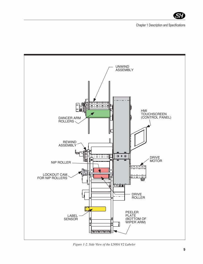
8 9Figure 1-2. Side View of the L500A V2 Labeler
Chapter 1 Description and Specifications
REWINDASSEMBLY
PEELERPLATE(BOTTOM OFWIPER ARM)
HMITOUCHSCREEN(CONTROL PANEL)
UNWINDASSEMBLY
DRIVEROLLER
NIP ROLLER
LOCKOUT CAMFOR NIP ROLLERS
DRIVEMOTOR
LABELSENSOR
DANCER ARMROLLERS
L500A V2 High Speed Labeler Manual
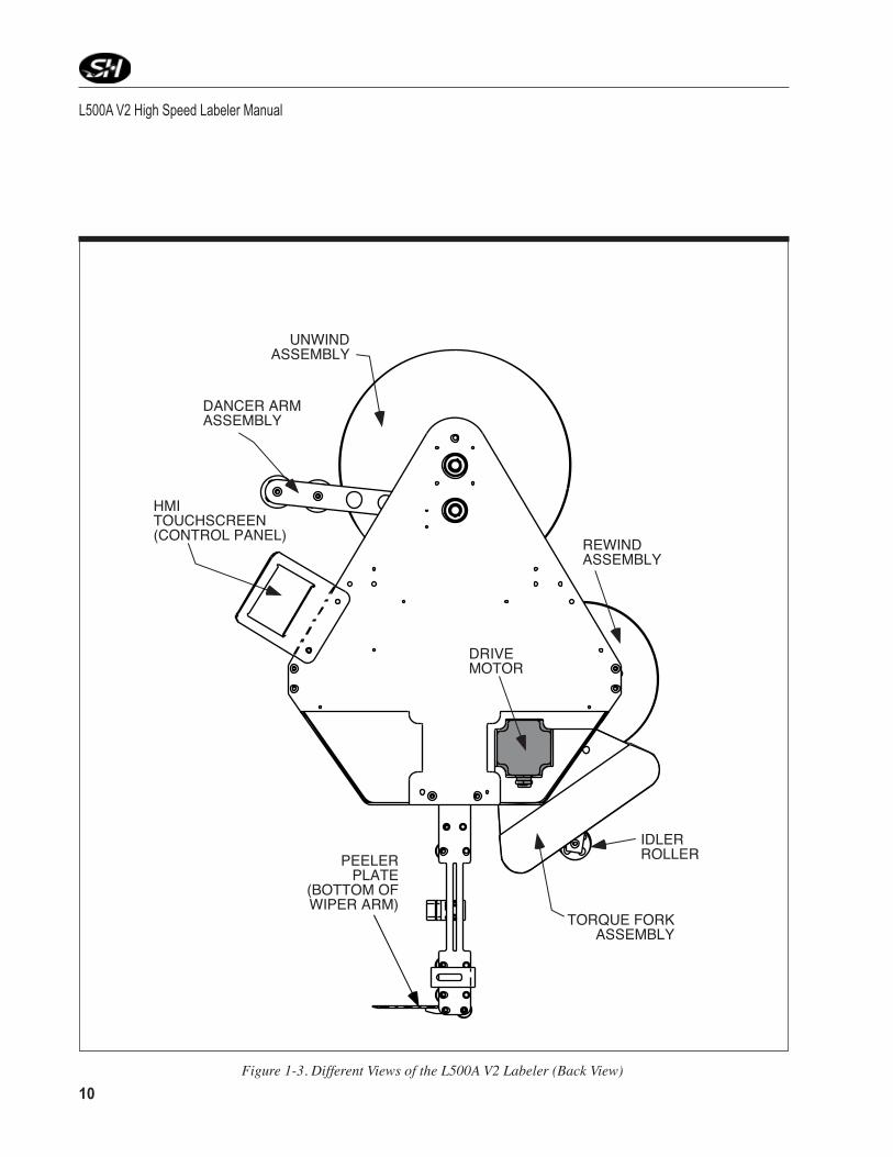
10 11Figure 1-3. Different Views of the L500A V2 Labeler (Back View)
TORQUE FORKASSEMBLY
HMITOUCHSCREEN(CONTROL PANEL)
UNWINDASSEMBLY
IDLERROLLER
DANCER ARMASSEMBLY
DRIVEMOTOR
REWINDASSEMBLY
PEELERPLATE
(BOTTOM OFWIPER ARM)

10 11
Chapter 1 Description and Specifications
Table1-1.ApplicatorSpecifications
Applicator Specifications Themanufacturerordistributormayhavechangedspecificationstomatchyourapplication.PleaserefertoTable1‑1forapplicatorspecifications.
Applicator SpecificationsAccuracy ±0.02" (±0.5mm) depending on the application moduleControls Dual processorProduct Detection Photo sensorLabel Sensor CapacitancePower Requirements 115 VAC, 60 Hz, single phase, 6 AmpShop Air (For Modules Only) 80 psi minimum, 100 psi maximum to the filter/regulatorEnvironment 41-104˚F (5 to 40˚C) operating temperatureRelative Humidity 25-85% relative non-condensing humidityLabel Supply Roll 14" (356mm) outer diameter with 3" (76mm) spool inner diameterOveral Dimensions of Applicator 30.9" wide x 28.5" tall x 18" deep (784.9mm x 723.9mm x 457.2mm)Weight Approximately 150 lbs (68kg)

L500A V2 High Speed Labeler Manual
12 13
Notes

12 13
Warnings and Conditions Turn Off Power! Before servicing, make sure you have turned off the
compressed air and electrical power in a way which prevents accidental reactivation. Padlock and clearly tag the appropriate electrical and pneu‑matic disconnects. Wait at least two (2) minutes after disconnecting the electrical power to discharge the motor start capacitor before performing any electrical servicing with the rear cover removed.
Dress Appropriately! Reduce the risk of injury from moving parts by securing loose sleeves and other clothing. Do not wear loose jewelry or neckties near the machine. Wear safety glasses or other protective eyewear at all times. Never place hands or tools near the tamp, corner wrap, print head, or any other movable parts when the machine is operating.
Install Safety Covers! Make sure the machine remains safe to operate. Be sure all safety covers have been installed before operating this ma‑chine. Safety covers include any covers installed by your direct supplier, as well as the main cover and the print engine cover. Each helps protect the operator from potential pinch points and moving parts.
Avoid Pinch Points! Exposed pinch points include the unwind and take up assemblies, air tamp, and corner wrap modules. Pinch points exposed when the main cover is removed include the dual clutch assemblies.
Avoid Dangerous Conditions! The standard labeler should not be placed in washdown environments. Dry conditions are critical for long life. Normal operator inherently causes static electricity to build up. Avoid explosive or potentially explosive environments.
Safety Precautions
Figure 2-2. Additional Safety Warning Labels - Hand Crush, Finger Cut, Hand in Gears.
2

L500A V2 High Speed Labeler Manual
14 15
Notes

14 15
This chapter covers unpacking, inspection, positioning and power hookups for the label applicator.
Unpacking and Inspection Step 1. Check the Shipping Container. The shipping container protects the ap‑
plicator under most circumstances. Visually inspect the outside of the shipping container. Report any crate or equipment damage to the ship‑ping carrier immediately.
The Applicator can weigh in excess of 150 lbs (68kg).
Step 2. Unpack the Applicator. Remove the top and sides of the shipping crate to expose the Applicator. Remove the packing material. Inventory the container.
Applicator Positioning The standard mounting procedure uses the two mounting holes that are
located on each side of the applicator. The optional U‑arm supports the applicator at those mounting locations. The mounting holes are tapped to M12 x 60.
Positioning of the labeler may vary if an application module was pur-chased with your unit.
Applicator Installation3

L500A V2 High Speed Labeler Manual
16 17
The labeler must be positioned so that labels are applied to the product with the proper orientation. Once the correct orientation is obtained, the labeler is ready to be placed into position. The product and labeling surface should be parallel with each other at point of contact. (Refer to Figure 3‑1.)
Figure 3-1. Correct/Incorrect Positioning
PRODUCT PRODUCT
THE TWOSURFACESSHOULD BEPARALLEL NOT
PARALLEL
CORRECT INCORRECT

16 17
Chapter 3 Applicator Installation
Figure 3-2. Rotation Adjustment
Rotation adjustment of the wiper arm and peeler tip (refer to Figure 3‑2) shouldbemadetolocatetheflagofthelabelasclosetotheproductaspossible. The peeler tip should be located just above the product. A ref‑erenceof0˚(zerodegrees)fromtheproductissuggestedonthewiperarm. Then, rotate the peeler tip as needed.
Note: Theflagofthelabelistheamountoflabelprotrudingpastthepeelertip.
Placing the peeler tip in the path of the product may cause damage to the applicator.
The applicator needs to be mounted in such a way that there is mini-mum vibration and rotation, or else the accuracy of the labeling may be compromised. It is also suggested that fine tuning adjustments be made after mounting.
PRODUCT
PEELERTIP
WIPER ARM
90˚
103˚

L500A V2 High Speed Labeler Manual
18 19
U-Arm & T-Stand If a T‑stand and/or U‑arm is purchased with your unit, refer to Figures 3‑3 and 3‑4 for proper positioning.
To pivot the applicator up or down, loosen the large hex nut which fastens the U‑arm to the T‑stand. This allows the unit to rotate the peeler tip up or down. Tighten the same nut to secure the applicator's position. (Refer to Figure 3‑4.)
The applicator may also be positioned for top, side, or bottom panel labeling. Loosen the two large socket head bolts that fasten the U‑arm to the labeler. Rotate the applicator into a position where the application module is parallel to the surface of the product to be labeled.
Figure 3-3. U-Arm
SOCKET HEAD ADJUSTMENT
SOCKET HEADADJUSTMENT
MOUNTING HOLE
MOUNTINGBOSS

18 19
Chapter 3 Applicator Installation
Figure 3-4. Adjustment for T-Stand and U-Arm
Use the handle at the top of the T‑stand to raise or lower the applicator to the desired height relative to the product. (Refer again to Figure 3‑4.)
To change the horizontal position of the unit, simply unlock the casters on the bottom of the T‑stand and roll the unit to the desired location. Lock the casters down once in position.
MOUNTING BOSS FOROPTIONAL LEVELING FEET
LOCKINGCASTERS
SOCKET HEADBOLTS FOR
TOP OR SIDE-PANEL
LABELINGADJUSTMENTS
HEX NUTFOR PEELER
TIP MOVEMENT
CAMLOCK
HANDLE FORVERTICALMOVEMENT

L500A V2 High Speed Labeler Manual
20
Remote Electrical Enclosure /Interface Panel Connections for the interface panel are found on the remote electrical
enclosure (see to Figure 3‑5.) These connections are easily accessible for quick changeover between modes of operation. The following is an explanation of each device:
Figure 3-5. Interface Panel on Remote Enclosure
ON
OPERATORINTERFACE
ENCODER
LABELSENSOR
PRODUCTSENSOR
LOW LABELSENSOR
OperatOr Interface: Plug in which the Operator Panel is connected. Cycling power is required when connected or disconnected.
encOder: Plug in which an optional encoder is connected. The encoder is used for synchronous mode labeling, which can apply the label at the speed the product is traveling. It is recommended to use an incremental encoder with at least 1024 increments.
LOW LabeL SenSOr: Plug in which the low label sensor is connected. The low label sensor is found behind the unwind assembly wheel.
prOdUct SenSOr: Plug in which the product sensor is connected.
LabeL SenSOr: Plug in which the label sensor is connected. The label sensor is found on the wiper arm assembly.
dIScOnnect SWItcH: Allows the operator to complete disconnect power to the labeler, or connect power. Turn ON to connect power; Turn to OFF to disconnect power.

21
Chapter 3 Applicator Installation
Power Supply Supplying the unit with the correct supply voltage and compressed air
(ifnecessary)permitssafeandefficientoperation.(RefertoTable1‑1forexactspecifications.)
Note: Compressed air is only needed with certain applicator modules.
Verify Main Power The applicator is supplied with a power cord for AC operation. Plug the power cord into an outlet with the proper voltage and ground. Make sure the power cord is securely connected to the labeler and the outlet.
To test the connection, turn the disconnect switch to “ON” (see Figure 3‑5). The HMI display will illuminate after approximately 30 seconds; this will verify the power connection.
Note: It takes a minimum of approximately 30 seconds for system to boot.

L500A V2 High Speed Labeler Manual
22 23
Notes

22 23
Label Style Stripped out form only, with a minimum spacing of 0.125" (3 mm). Remove all die cut waste (skeleton). Label back-ing must have a release agent such as silicon. Label must free peel when pulled around a standard peeler plate with a minimum label gap of 0.125" (3 mm).
Accuracy (A) Linear position of label relative to web or backing must be centered.
(B) Die cutting and edge slitting must be controlled to avoid cutting or nicking of the web backing. Failure to regu-late this will result in web failure and label dispensing problems.
(C) Web must be a minimum of 0.25" (6 mm) wider than label to be dispensed.
Roll Put-Up Maximum O.D. of roll is 14" (356mm) with a core I.D. of 3" (76 mm). Label orientation is based on equipment and product orientation. The labels must be wound to the outside of the roll.
Splices Splices should be avoided as much as possible, but when splices are needed, please use "Angle" style, flush to the edge and on both sides of backing using 1" (25 mm) cellophane splice tape. Replace the label in the spliced area.
Label Tolerance A label tolerance of +0.05" (0.02mm) can be maintained provided that:
(A) Labels are manufactured to the right label specifica-tion with no die cuts into liner.
(B) Lateral position of labels are within 0.0025" (0.06 mm) on the x and y axes.
do not use foil or metal labels with capacitance sensor. they will damage the label sensor.
Label Threading Only use labels that can be stripped out. More information on label and
webspecificationsareavailableinTable4‑1.
Before installing a label roll please read Table 4-1 to insure the selec-tion of proper label stock.
Applicator Setup
Table 4-1. Label & WebSpecifications
Label & Web Specifications
4

L500A V2 High Speed Labeler Manual
24 25
13
5
2 4
6
7
9
1012
8
11
13
1416
1517
18
Refer to Figure 4‑1 to assist in proper label threading. A label threading diagram is supplied on the front of the labeler.
Store label stock in a cool, dry place to avoid heat damage.
Figure 4-1. Web Path (Label Threading Path)

24 25
Chapter 4 Applicator Setup
Procedure Refer to the circled numbers (1 through 18) on the front of the Labeler as shown in Figure 4‑1 to assist you in following this label threading procedure.
Step 1. Remove Outer Flange. With the power off, remove the outer disk from the unwind roller by releasing the handles and lifting the cover up and off the unwind extrusion. If there is any unused spool, remove that from the extrusion.
Step 2. Install Label Core. Install a new spool of labels. Make sure the supply rollispushedtotheinnerunwindflangeoftheassembly.Replacetheouterflangebyaligningthetabswiththegroovesontheextrusion(seeFigure4‑2).Oncetheouterflangeissliddownoverthespoolalongthegrooves,firmlyseattheouterflangedownoverthespool,andpushthetabs into the core of the spool.
Step 3. Start to Thread the Label Stock. Whileholdingtheinnerflange,graband tug the label stock to make sure the roll does not slip. Once secure, loop the label stock under the idler roller (refer to position #1). Then loopthelabelstockoverthefirstdancerarmroller(position#2).Routethe stock to the inside of the idler shaft (position #3) and back up to the outside dancer arm roller at position #4).
Figure 4-2. Unwind Assembly - Installing New Label Spool
UNWINDEXTRUSION
GROOVES
TABS NEW LABELSTOCK SPOOL
UNWINDFLANGE

L500A V2 High Speed Labeler Manual
26 27
Step 4. The Nip Roller. To thread the stock between the drive roller and the nip roller,youmustfirstreleasethetensionontheniprollers.Liftuponthelockout knob on top of the face plate cover (see Figure 4‑3) and rotate them180˚.Moveeachcamoutwarduntilthecams'locksdropbackdown into the slots. This locks the nip rollers away from the drive shaft. Thread the label stock between the nip roller (position #5) and the drive shaft.
Figure 4-3. Lockout Knobs for Nip Rollers
Step 5. Wiper Arm. Threadthelabelstockunderthefirstidlerroller(refertoposition #6), and then through the second roller (position #7). The label then is threaded through the label sensor (position #8) and under the third idler roller (position #9), then around the 4th roller (position #10). The label stock over the end of the label peeler plate (position #11), and back to the last wiper arm idler roller (position #12) at the base of the wiper arm.
DRIVESHAFT
IDLER ROLLERON WIPER ARM
LOCKOUTCAM FOR NIP
ROLLER #2NIP ROLLER#1
LOCKOUTCAM FOR NIPROLLER #1

26 27
Do not use foil or metal labels with capacitance sensor. They will dam-age the label sensor.
Step 6. Second Nip Roller. Thread the label back up towards the drive shaft, feeding the label between the drive shaft and the 2nd nip roller (refer to position #12).
Step 7. Torque Fork Assembly. Pull the labeldownto thefirstTorqueForkAssembly idler roller (refer to position #14), up to the 2nd idler roller (position #15), back down to the third idler roller (position #16), and finally,aroundthelastidlerroller(refertoposition#17).
Step 8. Open the Cam on the Rewind Assembly. Open the cam (refer to Figure 4‑4) on the extrusion shaft of the rewind assembly. Insert a portion of the end of the label into the cam, and rotate the wheel to wrap up excess label stock. The label stock (media) should be riding evenly on the rollers and the tension should be fairly secure, but not too tight.
Chapter 4 Applicator Setup
Figure 4-4. Rewind Assembly - Threading
LIFT UP ON PIN TO MOVE HANDLE
CAM OPENS SLOT IN EXTRUSION, ALLOWING YOU TO INSERT LABEL MEDIA END INTO OPENING HERE
REWIND�WHEEL
U-ARM

L500A V2 High Speed Labeler Manual
28 29
Step 9. Re-engage the Nip Roller Lockout Knobs. Re‑engage the nip roller lockoutknobsbyturningtheknobs180˚, liftingupontheknobsandpulling them center towards the drive shaft (this should be tight, and maintainafirmgripontheknobs).Oncetheniprollersareinplace,pushthe knobs down into the openings on the front cover (see Figure 4‑3).
Step 10. Power Up and Jog the System. Turn the disconnect switch to "ON". On the keypad, use the JOG command to run labels through at high speed to helpthelabelstockfinditsproperlabelpaththroughthelabeler.Oncethe label stock is properly positioned, jog the labeler at low speed to position the label on the peeler plate appropriately.
Step 11. Using Label Teach in the Control Screens. Once the label is correctly situated on the peeler plate, go to the Label Teach screen and press "EN‑TER". This allows the labeler to "learn" the label position. The labeler should dispense three labels off the end of the peeler plate. Refer to Chapter 6, Operator Interface, for further information.
Note: The aforementioned information is also valid if the labeler is still running (power not turned "OFF"), but to obtain label stock to thread, the dancer arm will have to be pulled clockwise. The dancer arm will dispense the necessary label stock to thread through the labeler.

28 29
Low Label Sensor (Optional) The low label sensor is installed as shown in Figure 4‑6 on the back
side of the labeler near the unwind shaft (it is not visible unless the side covers of the labeler are removed). This sensor detects when the label roll is depleted. When the sensor detects the low level of media, it sends a signal and illuminates the amber light on the light tower (refer Figure 4‑5). This sensor is hard wired to terminals in the electrical enclosure (see Appendix for details).
Chapter 4 Applicator Setup
Light Tower (Optional)The optional light tower (refer to Figure 4‑5) can be connected to the labeler to indicate different conditions of the labeler at any given time.
Figure 4-6. Low Label Sensor
Figure 4-5. Light Tower
RED -
AMBER -
GREEN -
INDICATES LABELER ISNOT READY; FAULTED
INDICATES A LOW LABELSITUATION
INDICATES LABELER ISREADY; RUNNING

L500A V2 High Speed Labeler Manual
30 31
Rewind Clutch Adjustment Adjust the rewind assembly so the label stock rewinds smoothly. No
snapping or slack should occur. Adjust the rewind assembly by turning the hex nut on the end of the rewind shaft clockwise or counterclockwise.
To increase feed rate, turn the nut clockwise to apply more friction to the friction washer located on the rewind assembly. To decrease feed rate, turn the nut counterclockwise which applies less friction to the friction washer (see Figure 4‑7.)
Astherewindassemblyfills,therewindingspeedmaybecometooslow.This is due to the increased weight of web waste on the rewind assembly. To prevent a slowdown from occurring, adjust the rewind speed as if the rewind assembly was full. Initially, the rewind assembly may exert substantial tension on the web. This will ease as the rewind assembly fillswithcollectedwebwaste.
Figure 4-7. Rewind Clutch Adjustment
TIGHTEN (CLOCKWISE)
LOOSEN (COUNTER-CLOCKWISE)

30 31
Chapter 4 Applicator Setup
Product Sensor The sensor supplied with the applicator is connected directly to the mod‑
ule interface panel. This allows for quick changeover of sensor style as applications dictate. (Note: This is not used when the labeler is used in Rotary applications.)
The sensor is shipped with a mounting bracket that should be mounted slightly upstream from the applicator.
The alignment and method of mounting is critical to the performance of the sensor (see Figure 4‑8.) Excessive vibration may cause false read‑ings. Anything behind the product that could cause a false sensor reading should be moved or placed as far away as possible.
Figure 4-8. Product Sensor Setup
��
PARAMETER = 0 to detect rising product sensor signal edge
Sensor output signal to +24V if sensor detects a productSensor output signal to 0V (or open output) when sensor is not detecting a product
PARAMETER = 1 to detect falling product sensor signal edge
Sensor output signal to +24V when sensor is not detecting a productSensor output signal to 0V (or open output) when sensor detects a product

L500A V2 High Speed Labeler Manual
32 33
To select between sensing the leading edge or the trailing edge of a product leave the sensor operate switch set to "light operate" at all times. In the PRODUCT SENSOR EDGE screen of the operator interface select (0) (DETECT RISING PRODUCT SENSOR SIGNAL EDGE) to detect the leading edge, or select (1) (DETECT FALLING PRODUCT SENSOR SIGNAL EDGE) to detect the trailing edge. The default setting is (1).
The standard sensor that is shipped with the labeler is set up for "light operate." Refer to Figure 4‑9 for adjustments.
Changing the sensor setting from light operate to dark operate will drastically affect the operation of the applicator and any modules being used.
Once the sensor is mounted and the product is in place, apply power and advance the GAIN control to maximum (clockwise rotation). If thesensoris“seeing”itsreflectedlight,thesensoralignmentredLED
Figure 4-9. Product Sensor Setup
Gain
������������� THIS IS A 15-TURN CLUTCHED POTENTIOMETER.
TURN CLOCKWISE TO INCREASE GAIN; TURN COUNTERCLOCKWISE TO DECREASE GAIN.
�������������� THE RED LED LIGHTS WHEN THE SENSOR SEES ITS
OWN LIGHT SOURCE, AND PULSES AT A RATE PROPORTIONAL TO THE RECEIVED LIGHT SIGNAL.
LIGHT/DARK OPERATE SWITCH: IN LIGHT-OPERATE (FULLY CLOCKWISE) MODE,
THE SENSOR ACTIVATES AN OUTPUT WHEN THE OBJECT IS PRESENT.
IN DARK-OPERATE (FULLY COUNTER-CLOCKWISE)
MODE THE SENSOR ACTIVATES AN OUTPUT WHEN THE OBJECT IS ABSENT.

32 33
Chapter 4 Applicator Setup
should be on. If a red pulse is not observable, reduce the GAIN control (counterclockwise rotation) to obtain a countable pulse rate.
Once you feel comfortable with the set GAIN, test by removing the object
from the sensing position. The red LED indicator should go “off”. If the LEDindicatordoesnotgo“off”,thesensorisreactingtolightreflectedfrom a background surface.
Reduce the GAIN until the indicator goes “off” and check the sensor with the object once again. If the sensor indicator does not come “on”, when the object is placed in position, then the sensor is receiving more light energy from the background than the object. Consider the following alternatives:
• Move the sensor closer to the object and reduce the sensitivity
(GAIN).
• Reducebackgroundreflectivenessbypaintingthebackgroundwithflat,blackpaint,scuffingthebackgroundorcuttingaholeinit.
• Tilt the sensoror thebackgroundso that the sensingbeam isnotperpendicular to the background.
Lion LRD 2100 Label Sensor Overview The Lion LRD 2100C Label Sensor is an electronic, capacitive sensor
used to count labels and/or monitor label registration. The NPN and PNP outputs show whether the sensor sees the leading or trailing edge of the label as it passes through the sensor.
Warnings/Precautions • MakesuresensorbodyisconnecttoGROUND.
• Unusedwiresmustbeinsulatedfromcontactwithotherobjects.
• Allpowermustbeoffwheninstallingthesensor. • Graywire(OutputPolarity,pin5)mustbeconnectedto+Vor
Ground for operation.
L500A V2 High Speed Labeler Manual
34 35
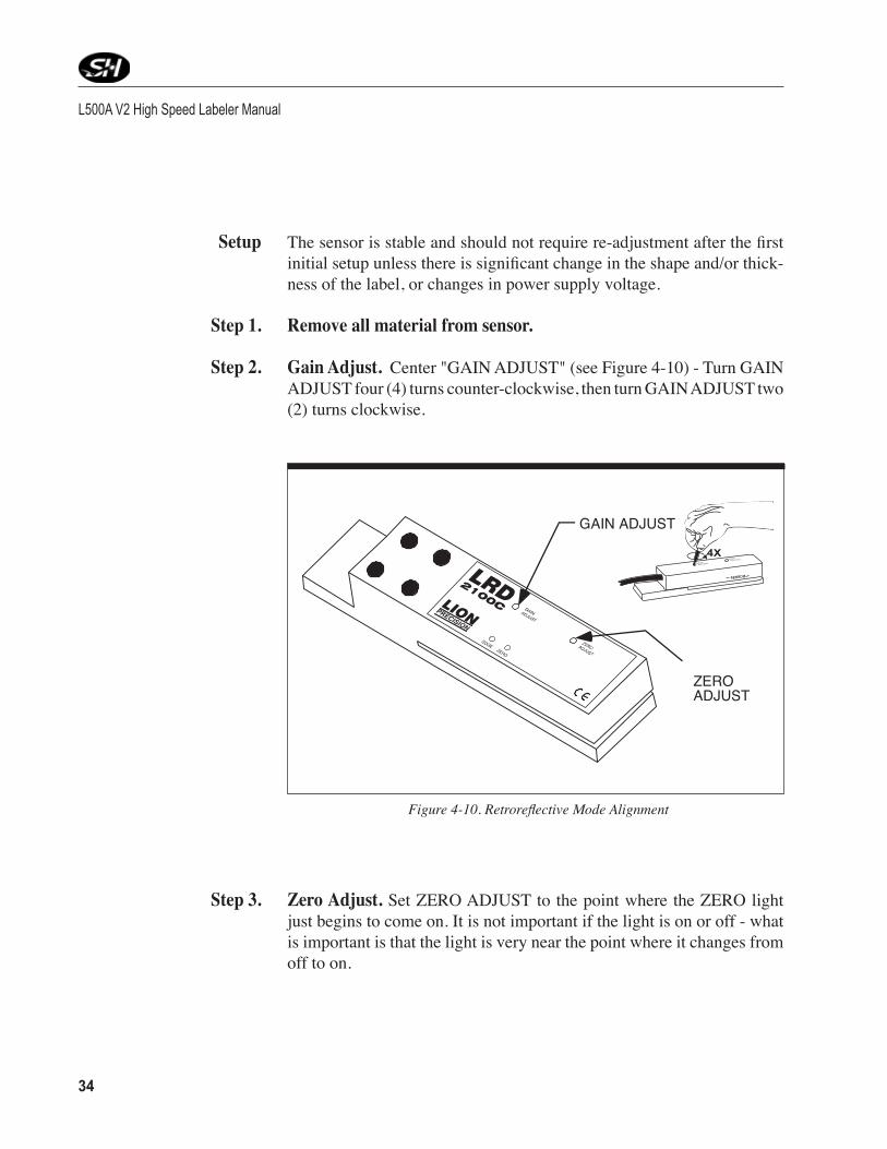
Setup Thesensorisstableandshouldnotrequirere‑adjustmentafterthefirstinitialsetupunlessthereissignificantchangeintheshapeand/orthick‑ness of the label, or changes in power supply voltage.
Step 1. Remove all material from sensor.
Step 2. Gain Adjust. Center "GAIN ADJUST" (see Figure 4‑10) ‑ Turn GAIN ADJUST four (4) turns counter‑clockwise, then turn GAIN ADJUST two (2) turns clockwise.
Figure4-10.RetroreflectiveModeAlignment
G A INA D J U S T
Z E R OA D J U S T
4X
GAIN ADJUST
ZEROADJUST
Step 3. Zero Adjust. Set ZERO ADJUST to the point where the ZERO light just begins to come on. It is not important if the light is on or off ‑ what is important is that the light is very near the point where it changes from off to on.
34 35
Chapter 4 Applicator Setup
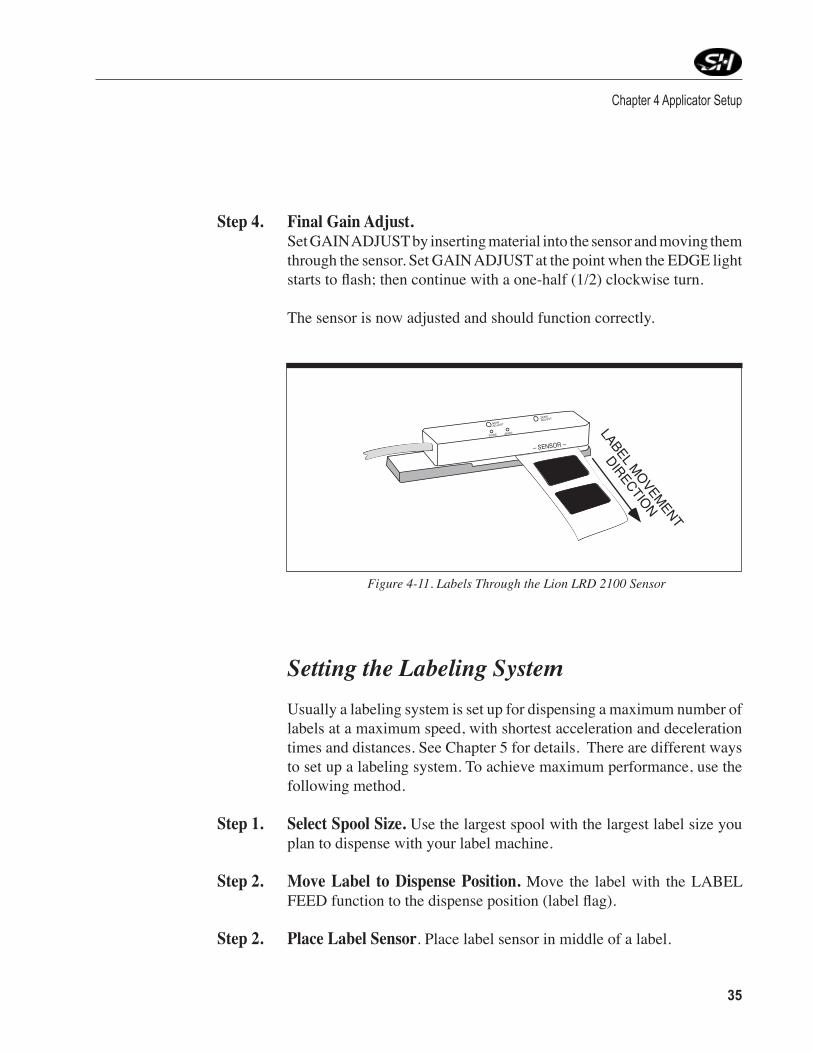
Step 4. Final Gain Adjust. Set GAIN ADJUST by inserting material into the sensor and moving them
through the sensor. Set GAIN ADJUST at the point when the EDGE light startstoflash;thencontinuewithaone‑half(1/2)clockwiseturn.
The sensor is now adjusted and should function correctly.
Figure 4-11. Labels Through the Lion LRD 2100 Sensor
EDGE ZERO
GAINADJUST
ZEROADJUST
– SENSOR –
LABEL MOVEMENT
DIRECTION
Setting the Labeling System Usually a labeling system is set up for dispensing a maximum number of
labels at a maximum speed, with shortest acceleration and deceleration times and distances. See Chapter 5 for details. There are different ways to set up a labeling system. To achieve maximum performance, use the following method.
Step 1. Select Spool Size. Use the largest spool with the largest label size you plan to dispense with your label machine.
Step 2. Move Label to Dispense Position. Move the label with the LABEL FEEDfunctiontothedispenseposition(labelflag).
Step 2. Place Label Sensor. Place label sensor in middle of a label.

L500A V2 High Speed Labeler Manual
36 37
Step 4. Run Auto-Teach Function. Run the AUTO‑TEACH function. If sys‑tem stalls, reduce the ACCELERATION/DECELERATION RAMP and START STOP SPEED until the stalling subsides.
Note: DefaultsettingforACCELERATION/DECELERATIONRAMPandSTARTSTOP SPEED is 50.
Step 5. Set Asynchronous Speed. If you know the maximum labeling speed already, set it as the ASYNCHRONOUS SPEED in the parameters then dispense labels in asynchronous mode. If you do not know the maximum labeling speed, increase the labeling speed (from the Wipe‑On Screen) step‑by‑step,andfindoutatwhichpointthesteppingmotorstalls.Ifthemotor stalls, reduce the maximum speed back to a safe rating.
Note: This value can be adjusted in the Wipe-On Screen - See Chapter 5.
Step 6. Decrease Acceleration/Deceleration Ramp. Continue dispensing labels. Now decrease the ACCELERATION/DECELERATION RAMP, step‑by‑step, starting from the default 50 ms. If the motor stalls, increase the maximum acceleration /deceleration ramp back to a safe rating.
Note: Please consider that a high acceleration rate may stress the web and
create a loose condition.
Step 7. Setup Complete. As a result of the actions 1 to 6, the system is now set up for maximum performance.
Note: Reference all BOLD CAPPED terms in Operator Interface Chapter.

36 37
Chapter 4 Applicator Setup
Right-Hand to Left-Hand Conversion The L500A V2 Applicator can be converted from dispensing labels from
the right, to dispensing labels to the left. The disassembly and reassembly of the applicator requires no additional parts. Attention to detail, a large clean workbench, and the following tools are recommended:
a External Snap Ring Pliers a Metric Allen wrench set a Needle nose pliers a 10mm combination wrench a Slip Joint Adjustable pliers a Rubber mallet a Jewelers Flat Head screwdriver a Loctite "242“ (removable) or equivalent
Overview: This is a shortened list of steps to complete changeover. Use the pro-cedures on the following pages for complete changeover from Right Hand to Left Hand label applications.
a Turn off Labeler (Use Disconnect Switch). a Disconnect External Cables. a Remove Wiper Arm Assembly. a Remove Side Covers. a Remove Torque Fork Assembly. a Remove Wiper Arm Assembly. a Remove Back Panel. a Remove the Rewind Components. a Remove Motor Assembly. aSwitch Motor and Side Standoffs. aReinstall Rewind Components. aReinstall Motor Assembly. aSwitch the Dancer Arm Components. a Reinstall Back Panel. a Reinstall Torque Fork Assembly. a Reinstall Wiper Arm Assembly. a Reinstall Bottom, Top, Side and Motor Covers. a Reconnect External Cables. a Test the Applicator.
L500A V2 High Speed Labeler Manual
38 39
Changeover Procedures Step 1. Turn the power off (using the disconnect switch) and disconnect all of
the remaining external cables from the Remote Electrical Panel. Remove any label media and the label sensor, and place the labeler horizontally on a table where you are able to access the entire labeler.
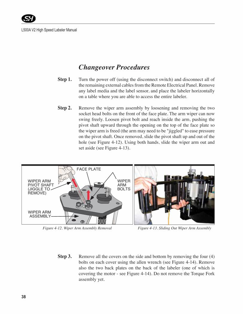
Step 2. Remove the wiper arm assembly by loosening and removing the two socket head bolts on the front of the face plate. The arm wiper can now swing freely. Loosen pivot bolt and reach inside the arm, pushing the pivot shaft upward through the opening on the top of the face plate so the wiper arm is freed (the arm may need to be "jiggled" to ease pressure on the pivot shaft. Once removed, slide the pivot shaft up and out of the hole (see Figure 4‑12). Using both hands, slide the wiper arm out and set aside (see Figure 4‑13).
Step 3. Remove all the covers on the side and bottom by removing the four (4) bolts on each cover using the allen wrench (see Figure 4‑14). Remove also the two back plates on the back of the labeler (one of which is covering the motor ‑ see Figure 4‑14). Do not remove the Torque Fork assembly yet.
Figure 4-12. Wiper Arm Assembly Removal
WIPER ARMPIVOT SHAFT(JIGGLE TOREMOVE)
WIPER ARMASSEMBLY
WIPERARMBOLTS
FACE PLATE
Figure 4-13. Sliding Out Wiper Arm Assembly

38 39
Chapter 4 Applicator Setup
Step 4. Remove the Torque Fork Assembly by loosening and removing the two hex nut screws on the face of the assembly (see Figure 4‑16 and 4‑17). Set the assembly aside.
Figure 4-14. Side Cover Removal
Figure 4-15. Side Cover Removal
DRIVEMOTOR
BACKPLATES
(STAINLESSSTEEL)
Figure 4-17. Torque Fork Assembly Hex Nuts Locations
REWINDASSEMBLYWHEEL
TORQUE FORKASSEMBLY
HEX NUTSCREWS
Figure 4-16. Torque Fork Assembly Hex Nuts
REWINDASSEMBLY
TORQUEFORK
ASSEMBLY REMOVETHESE TWO
(2) HEXNUTS

L500A V2 High Speed Labeler Manual
40 41
Step 5. Turn the labeler to an “upright” or vertical position. At the top of the back panel, remove the retaining (snap) rings from the Unwind Assem‑bly shaft and the Dancer Arm shaft (see Figures 4‑18 and 4‑19). There may or may not be shims associated with the retaining rings. Make sure you bag and tag the retaining rings and the shims - marking their original location.
Step 6. Loosen and remove the seven (7) screws on the back panel and set the back panel aside.
Figure 4-19. Retaining Ring, Shimand Shaft
RETAININGRING
SHIMSHAFT
4-18. Unwind Assembly and Dancer Arm AssemblyShaft Removal
DANCER ARM ASSEMBLY SHAFT (W/RETAINING RING)
UNWIND ASSEMBLY SHAFT
BACK PANEL
Step 7. Relieve the drive belt tension by loosening the tensioner’s jam nut (see Figure 4‑20) and then the tensioner bolt. Loosen, but do not remove, the two (2) socket head cap screws that holds the idler pulley.
Step 8. Support the motor and remove the four socket head cap screws which
attach the motor assembly plate to the four standoffs (see Figure 4‑20).
Step 9. Remove the motor and the mounting plate (with belt tensioner) as a single unit, from the back of the labeler and set aside.

40 41
Chapter 4 Applicator Setup
Step 10. Mark the motor mounting plate opposite the current motor side with a magicmarkertoidentifytheflipsideforreassembly.
Step 11. Remove the four socket head cap screws to release the motor from the
mounting plate.
Step 12. Remove the idler pulley from the mounting plate by removing the two socket head cap screws on the tensioner block.
Step 13. Mountthetensionerblocktotheflip(other)sideofthemotorassemblyplate (where the mark has been made from Step 10). The two mounting holes, the slot, and the notch on the block will line up on the assembly plate. Finger tighten the idler pulley.
Step 14. Reinstall the motor to the motor mounting plate.
Ensure the motor cable is facing towards the outside of the machine (opposite of the previous location).
4-20.BeltTensionerandMotorMountingPlatewithMotor
BELTTENSIONER
BELT TENSIONERSOCKET HEADS
BELTTENSIONER
JAM NUT
DRIVEBELT
SOCKET HEADCAP SCREWS (MOTOR MOUNT PLATE)
SOCKET HEADCAP SCREWS(MOTOR TOMOUNT)
MOTORCABLE

L500A V2 High Speed Labeler Manual
42 43
FRONT PANELOF LABELER
REWINDASSEMBLY
SETSCREW
Step 15. Remove the Rewind Flange (Assembly) from the front of the labeler by removing the screw located on the side of the Rewind Flange (the extrusion ‑ see Figure 4‑21). Note that the screw should be removed as shown in the drawing, in an “upside down” manner, or the screw will not come out of the shaft.
4-21. Rewind Flange Removal 4-22. Rewind Assembly Bearing Plate
EXTERNAL SNAPRING PLIERS
REWINDASSEMBLYBEARINGPLATE
REWINDASSEMBLYCLUTCH
DRIVEBELT
REWIND ASSEMBLYBEARING PLATESTANDOFF
Step 16. On the back of the labeler, remove the retaining ring and any associ‑ated shim from the Rewind Shaft. Remove also the retaining ring and any associated shim from the front of the labeler (see Figure 4‑22). If shims are used, make sure you bag and tag the retaining rings and the shims - marking their original location and that they are used when reinstalling the Rewind Shaft and Rewind Assembly.
Step 17. RemovethetwoflatheadscrewsfromtheRewindBearingPlateontherear of the labeler and set the plate aside.
Step 18. Remove the drive belt and set it aside. Now remove the Rewind Shaft and Clutch Assembly. This assembly will relocate to the other side of the labeler.

42 43
Chapter 4 Applicator Setup
Step 19. Remove the front cover‑to‑back cover side standoffs and switch to the other side of the labeler (see Figure 4‑23). Move the three (3) motor standoffs on the rear of the labeler to the oppo‑site side. Only three of the four standoffs need to be re‑located. The manufacturer has preinstalled the other one (see Figure 4‑24.)
REWIND CLUTCHASSEMBLY
FRONT COVER - TO-BACK COVER SIDE
STANDOFF
4-23. Side Standoff Locations
Step 20. Remove and reinstall the two (2) Rewind Assembly Clutch standoffs to the other side.
4-24. Standoff Relocation from One Side to the Other
REWIND CLUTCHASSEMBLY
REWIND ASSEMBLYBEARING PLATE
STANDOFFS
MOTOR MOUNTSTANDOFFS
(NEW LOCATION)MOTOR MOUNT
STANDOFFS(OLD LOCATION)
L500A V2 High Speed Labeler Manual
44 45
SHIM
REWINDASSEMBLYCLUTCHSTANDOFF
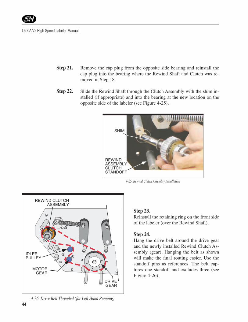
Step 21. Remove the cap plug from the opposite side bearing and reinstall the cap plug into the bearing where the Rewind Shaft and Clutch was re‑moved in Step 18.
Step 22. Slide the Rewind Shaft through the Clutch Assembly with the shim in‑stalled (if appropriate) and into the bearing at the new location on the opposite side of the labeler (see Figure 4‑25).
4-25. Rewind Clutch Assembly Installation
4-26. Drive Belt Threaded (for Left Hand Running)
MOTORGEAR
DRIVEGEAR
REWIND CLUTCHASSEMBLY
IDLERPULLEY
Step 23. Reinstall the retaining ring on the front side of the labeler (over the Rewind Shaft). Step 24. Hang the drive belt around the drive gear and the newly installed Rewind Clutch As‑sembly (gear). Hanging the belt as shown willmake thefinal routing easier.Use thestandoff pins as references. The belt cap‑tures one standoff and excludes three (see Figure 4‑26).

44 45
Step 25. Install the Rewind Clutch Bearing plate onto the end of the Rewind Shaft on the rear of the labeler.
Step 26. Reinstall the retaining ring and shim, if applicable, onto the end of the Rewind Shaft.
Step 27. Reattach the Rewind Flange to the front housing on the labeler (reversal of Step 15).
Step 28. Attach the Motor Assembly on the opposite side of the labeler. The belt path routing is critical and should be considered during this installa‑tion.
Step 29. Route the belt to engage the rewind drive gear, the idler pulley, the mo‑tordrivegear,driverollergear‑inthatorder.Thereisplentyoffingerroom to route the belt properly. Check that the belt runs true ‑ making any adjustments as necessary.
Step 30. Retension the belt and tighten the jam nut. Do not over tighten. The pul‑ley should be halfway or just beyond halfway of the slot’s full travel. A deflectionof1/8”whencheckedhalfwaybetweenthedrivegearandthe rewind gear is acceptable.
Step 31. Recheck that the belt runs true. Manually turn the rewind shaft to test.
Step 32.Unhook the spring between the dancer arm and the unwind shaft while supporting the dancer arm on the front of the labeler (refer to Figure 4‑27).
Chapter 4 Applicator Setup
DANCERARM
SPRING
UNWIND SHAFTBRAKEBELT
Figure 4-27. Dancer Arm Spring on Rear of Labeler

L500A V2 High Speed Labeler Manual
46 47
Step 33. Remove the unwind assembly (front of labeler) by unscrewing the knob until the extrusions comes off the shaft. There is a key on the shaft of the unwindflange‑setitaside(seeFigure4‑28).
Step 34. Remove the socket head cap screw at the dancer arm shaft and remove the dancer arm. The dancer arm’s socket head cap screw was set using (removable) Loctite “242”.
Step 35. Relocate the dancer arm bumper(s) to the other side of the front plate (refer to Figure 4‑29).
Figure 4-28 . Unwind Flange Shaft Key
BRAKE BELTUNWIND FLANGESHAFT - KEY
FRONT OFLABELER
DANCERARM
Figure 4-29. Dancer Arm Bumpers on Front of Labeler
BUMPERS(NEW
LOCATION)
BUMPERS(OLDLOCATION)

46 47
Chapter 4 Applicator Setup
Step 36.On the rear of the labeler, loosen the set screw in the cam at the end of the dancer arm shaft while supporting the control arm. Remove the cam (see Figure 4‑30).
Step 37. Remove the socket head cap screw in the control arm. Slide the control arm off the shaft.
Step 38. Loosen the set screw in the control arm holding the Dancer Arm Spring shaft in place, and pull the shaft out of the con‑trol arm. Flip it over to the other side, and retighten the screw. (See Figure 4‑31 and Figure 4‑32).
Step 39. Reinstall the Dancer Arm Shaft cam, but do not yet tighten.
Figure 4-30. Reversing the Brake Control Arm
BRAKE BELT
CAM - LOOSENSETSCREW ANDREMOVE CAM
CONTROLARM
DANCERARM SHAFT
Figure 4-31. Removing the Brake Belt
LOOSEN SET SCREW TOPULL CONTROL ARM OFFSHAFT
DANCERARM SHAFT
Figure 4-32. Reversing the Control Arm
SWITCH TO OTHER SIDE

L500A V2 High Speed Labeler Manual
48 49
Step 40. Reinstall the dancer arm by positioning it between the two bumpers on the front of the labeler and using the socket head screw. Reattach the spring to the spring arm (reversal of Step 34.)
Step 41. Reinstall the Unwind Wheel Assembly. Make sure you turn the knob until it is fully secured.
Step 42. Reinstall the back panel (including any shims.) Also reinstall the two
small back panels covering the motor and opposite side where the motor was previously located.
Step 43. Reposition the cam toward the micro switch and retighten.
Note: The cam will engage the micro switch using a different contact pointfrompreviousconfiguration.Onaleft-handapplicator,thecamlob is at the 4:00 o’clock position when in contact with the micro switch lever. On a right hand applicator, the cam lob is at the 1:00 o’clock po-sition when in contact with the micro switch lever.
Step 44. Set the Dancer Arm Limits.
Note: To adjust for the maximum adjustment and travel, pull the dancer arm down to the bottom rubber stop; rotate the cam until the electric brake disengages. Release the dancer arm and rotate the cam in the op-posite direction until the brake comes on.
Step 45. Turn the labeler back into a horizontal position to reinstall the Torque Fork Assembly (reversal of Step 4). The Torque Fork Assembly will now be located on the opposite side of the labeler from where it was previously located.
Step 46. Reinstall the Wiper Arm in the opposite direction and sliding the pivot post into the hole at the top of the Wiper Arm. Once the pivot shaft is inplace,reinstallthetwoshoulderboltsfixingtheWiperArminposi‑tion for labeling. The Label Sensor must be reinstalled in the correct (reversed) position (refer to Step 2).
Step 47. Reinstall the top, bottom, side and motor covers.
Step 48. Attach all of external cables.

48 49
Step 49. Turn on the disconnect and power up the labeler. The applicator will take 30 seconds to boot up.
Step 50. The motor direction needs to be changed. Enter the “PARAMETER SETUP” menu and enter the appropriate code to change the “Motor Direction” value. Toggle to the “MOTOR DIRECTION” screen and change the current setting to the appropriate configuration.A settingof “0” is needed for a clockwise (CW) rotation (positive) of the motor shaft (looking on top of the motor ‑ or right‑hand application), and a set‑ting of “1” is needed for a counterclockwise (CCW) rotation (negative) of the motor shaft (looking at the top of the motor shaft ‑ or left‑hand application.)
Chapter 4 Applicator Setup

L500A V2 High Speed Labeler Manual
50 51
Notes

50 51Figure5-1.MappingoftheOperatorInterface
Operator Interface5
HIGH-SPEED
LOW-SPEED
SINGLE STEP
LAB. PITCH
SPEED + / SPEED -
DELAY + / DELAY -
SPEED + / SPEED -
DELAY + / DELAY -
WIPE-ON ASYNCHRONOUS
SYNCHRONOUS
JOG��������� ���������������� ����������������
LABEL-TEACH
AUTO-CENTER AUTO-CENTER TEACH START
AUTO-CENTER OFF
AUTO-CENTER ON
TAMP-ON STOP
BLOW-ON STOP
TAMP-BLOW STOP
START DELAY
STOP DISTANCE
COMPENSATION SPEED
START COMPENSATION
STOP COMPENSATION
ASYNCHRONOUS SPEED
ACCEL./DECEL. RAMP
AUTO CENTER
FREE TIMER
IMPRINTER
RATIO ADJUST����������������������
PARAMETER - WIPE
PARAMETER PASSWORD
START/STOP

L500A V2 High Speed Labeler Manual
52 53Figure5-1(continued).MappingoftheOperatorInterface
TAMP DELAY
TAMP DWELL
VACUUM DELAY
VACUUM OFF DWELL
AIR ASSIST DELAY
AIR ASSIST DWELL
BLOW DELAY
BLOW DWELL
VACUUM DELAY
VACUUM DWELL
AIR ASSIST DELAY
AIR ASSIST DWELL
PARAMETER - BLOW
PARAMETER - TAMP
LOW-SPEED
HIGH-SPEED
ACCEL./DECEL. RAMP
PARAMETER - JOG
GEAR NUMERATOR
GEAR DENOMINATOR
LABEL PITCH
CURRENT REDUCTION
PRODUCT SENSOR EDGE
LABEL SENSOR EDGE
MOTOR DIRECTION
PASSWORD
PRODUCTS TO SKIP
MAX. MISSING LABELS
AUTO WEB ADVANCE
WEB ADVANCE SPEED
TIMER 1
PARAMETER - SETUP
��������� ���������������� ����������������PARAMETER
Continued on From Previous Page
PROGRAM NUMBER SELECTPROGRAM NUMBER
DIAGNOSTICS
TIMER 2
ENCODER/SENSOR DIAGNOSTICS

52 53
Operator Interface Map Thepreviouspagecontainsabriefflowchartoftheprogramlayout.Please
note that all the screens are accessible through the Operator’s Panel.
Note: Turn the labeler off (via the Disconnect Switch) before plugging the remote operator panel into the port. Then turn the power back on to access remote operator panel. Cycle power once remote operator panel is removed from the port.
Operator Interface Operation The following information explains the different parameters found
within the operator panel. These parameters are extremely important in obtaining a reliable labeling operation. The operator should take time to sample various settings and observe how they affect the performance of the labeler.
Operating Mode The two operating modes available are synchronous and asynchronous.
The operator may change between modes by simply selecting the appo‑priate mode in the “WIPE‑ON” screen.
When synchronous mode is chosen, the labeler will dispense labels at the speed determined by the encoder data sent to the controller. This mode is used for high speed, precise labeling or varying conveyor speed applications.
When asynchronous mode is chosen, the labeler will dispense labels at a constant speed determined by the values entered into the operator panel.
Chapter 5 Operator Interface
Additional information on the Controller can be found in the Berger Lahr C229 Single Axis Motion Controller manual (May, 2006).

L500A V2 High Speed Labeler Manual
54 55
The settings the operator enters into the operator panel will affect the labeler differently depending on the mode the operator has chosen.
Main Screen Main Screen Once powering up the applicator, the main screen is accessible after thirty
(30) seconds. Choose the operating function (JOG, LABEL‑TEACH, etc.) in order to set up the parameters for the different operating modes (refer to Figure 5‑2).
Figure5-2.MainScreen
BLS 2020 M188
SCRUP SCRDN ENTER
JOGLABEL-TEACHAUTO-CENTER
Scroll upin mainmenu
Pressenter
selectdesired
modeScrolldown
in menu
Operating Mode(Highlighted iscurrently selected)
Operational Modes:JogLabel-TeachAuto-CenterWipe-OnTamp-OnBlow-OnTamp-BlowParameter

54 55
Chapter 5 Operator Interface
Figure 5-3. Parameter Display Screen/Edit Screen and Function of Buttons on Screen
BLS 2020 M188
START DELAY+00000 [Increm]
PARAMETER - WIPE
SCRUP SCRDN -EXIT ENTER+
Scroll up in menu
Press enter to change
parameter
Parameter Name
Parameter Value
Parameter Group
Parameter Unit
Parameter
Display
Scroll down
in menu
Increase Digit Value
Store Value
and Exit
+ Shift to Left
Decrease Digit
Value
- Shift to
Right
Key Assignment of Parameter Menu: (lets the operator change the values on the parameter screen for that parameter)
Key Assignment of Parameter Display Menu: (shows the established values on the parameter screen for that parameter)
Parameter Display Screen

L500A V2 High Speed Labeler Manual
56 57
Operational Modes - Jog The JOG function is used to manually position the label to the correct
position at the peeler plate. It can also help to adjust the labeler dispens‑ing speed (using a tachometer) while in asynchronous labeling mode. Jog can only be used if you are not in any other Operational Mode (i.e.: Wipe‑On).
To use JOG, enter the JOG screen and select one of the four modes: HIGH SPEED, LOW SPEED, LABEL PITCH or SINGLE STEP. The values for High Speed and Low Speed can be set in the parameter section (Parameter ‑ Jog further in this chapter).
Once the desired speed is set, press the JOG button on the control panel to advance the label web.
The position counter displays the amount of steps that the motor has moved in positive direction after the JOG mode was started. The counter will be reset when the JOG mode is restarted.
Operational Modes - Label Auto-Teach This function is used to determine the length of a label pitch and the stop distances used for the labeling process. It begins when START
is pressed. The speed for the Label‑Teach mode is the low jog speed. Stepping motor controllers determine the position of the motor while the motor is running in relation to the label sensor input signal.
MENU MODE JOG
JOG HIGH SPEED+123
----- -----
HIGH SPEED JOG
Dispenses labels at a speed as set in the Parameter Jog Section.
LOW SPEED JOG
Dispenses labels at a speed as set in the Parameter Jog Section.
LABEL PITCHDispense labels at a speed which ASYNCHRONOUS speed is set to in the parameter screen (simulatesproduct sensor).
SINGLE STEP Dispenses labels one motion step at a time.

56 57
Chapter 5 Operator Interface
There are two ways to enter the label pitch and stop distance for the Label‑Teach operation:
Option 1. Measurelabelpitch(length+gap)andstopdistanceandenterasparam‑eters using the terminal. Note: All values are in motor steps.
Option 2. Place label web with manual function to the dispensing position. Then activate the LABEL_TEACH to start teach in procedure (Note: motor moves with the low jog speed).
While setting up the labeling machine, the JOG operation is required to move the label to the correct position at the peel plate. The LABEL‑TEACH learning movement function is used to determine the manually adjusted operating position for the AUTOMATIC OPERATION.
The LABEL‑TEACH learning movement is started by se‑lection LABEL‑TEACH in the main menu. The function advances the web 3‑4 label lengths with the manual low speed.
With the digital input LABEL_SENS a total of 3 label lengths including the gaps between the labels are measured and the average length of the 3 label lengths is then calculated as a set value (LABEL PITCH) then later used in the actual labeling operations.
Problems with the adjustment of the label sensor or with label web itself can be detected with the learning movement. It is required to move the label sensor further away from the label edge if the sensor is placed just at the label end after a learning movement, because this is a disadvanta‑geous position for the automatic operation.
Only after an error free LABEL‑TEACH learning movement all the measuring results are accepted by the controller and saved as operating parameters permanently to EEPROM.
1. Thelabelpitch(pitch=labellength+gapbetweenlabels) 2. The stop distance after detecting a label end signal.
Figure 5-4. Label Auto-Teach Screen
L500A V2 High Speed Labeler Manual
58 59
Operational Modes - Auto-Center Teach, Auto-Center and Encoder-Value Teach
This function is used to “teach” the product length and is used in combi‑nation with the AUTO‑CENTER function. (Refer to the Parameter‑Setup section later in this chapter for additional information on Auto‑Center parameter). Auto-Center only works in WIPE-ON synchronous dis-pensing mode.
The AUTO CENTER FUNCTION works properly if: a The RATIO ADJUST factor is set to the default value of 100%. The
gear numerator and gear denominator must be set accurately for this. Please refer to the section PARAMETER SETUP.
a The labeling mode is switched to synchronous. a The following steps are followed:
1. Switch controller to WIPE‑ON mode and synchronous dispensing modefirstandmakethatAUTOCENTERfunctionswitchedof.In case the AUTO‑Center icon is displayed switch the AUTO‑CENTERfunctionofffirst.
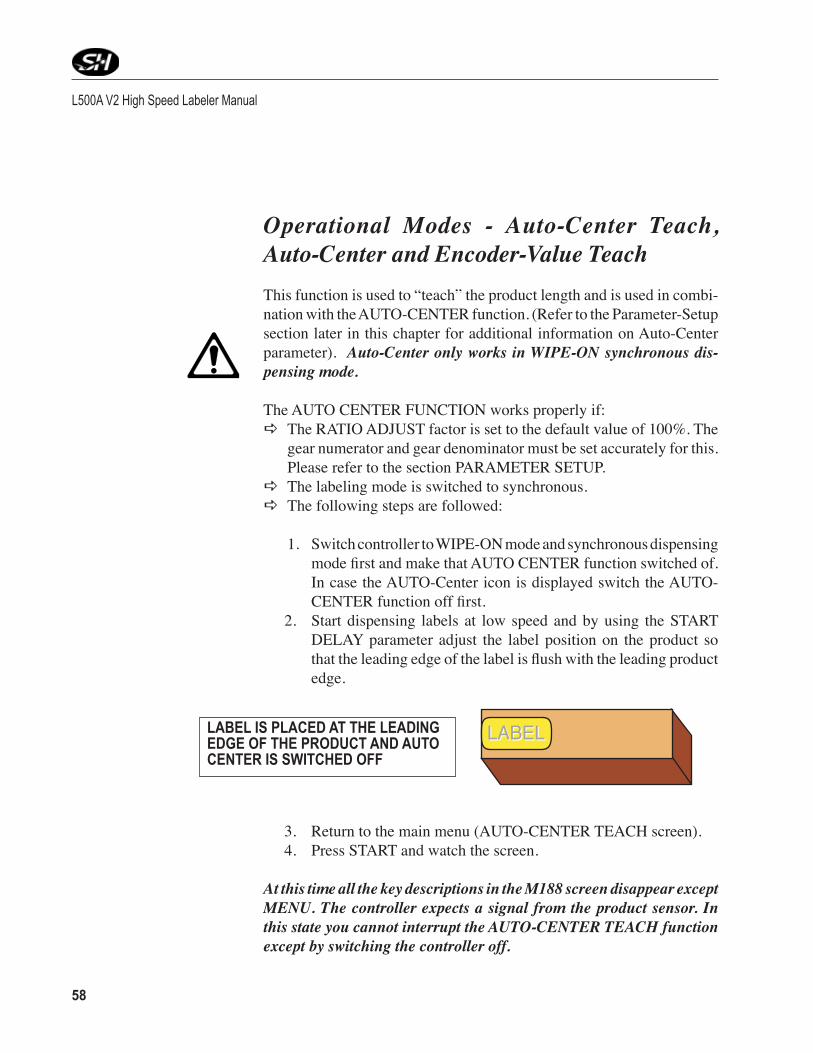
2. Start dispensing labels at low speed and by using the START DELAY parameter adjust the label position on the product so thattheleadingedgeofthelabelisflushwiththeleadingproductedge.
3. Return to the main menu (AUTO‑CENTER TEACH screen). 4. Press START and watch the screen.
At this time all the key descriptions in the M188 screen disappear except MENU. The controller expects a signal from the product sensor. In this state you cannot interrupt the AUTO-CENTER TEACH function except by switching the controller off.
LABEL IS PLACED AT THE LEADING EDGE OF THE PRODUCT AND AUTO CENTER IS SWITCHED OFF
LABELLABEL
58 59
5. Put the product on the conveyor and run it past the product sensor at low speed. The controller measures the length of the product in encoder increments. Product length: Leading product edge to trailing product edge detected by the product sensor.
6. The measured product length is displayed on the screen in incre‑ments. This value shows the encoder value. Enter this value for the Encoder value. If AUTO‑CENTER is not rquired, exit at this point.
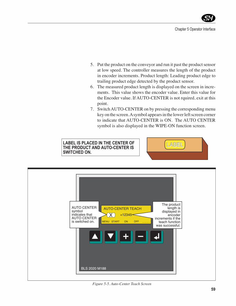
7. Switch AUTO‑CENTER on by pressing the corresponding menu key on the screen. A symbol appears in the lower left screen corner to indicate that AUTO‑CENTER is ON. The AUTO CENTER symbol is also displayed in the WIPE‑ON function screen.
Chapter 5 Operator Interface
Figure 5-5. Auto-Center Teach Screen
BLS 2020 M188
MENU START ON
AUTO-CENTER TEACH
OFF _ _ _ _
+12345X
AUTO CENTER symbol indicates that AUTO CENTER is switched on.
The product length is
displayed in encoder
increments if the teach function
was successful.
LABELLABELLABEL IS PLACED IN THE CENTER OF THE PRODUCT AND AUTO-CENTER IS SWITCHED ON.

L500A V2 High Speed Labeler Manual
60 61Figure5-6.Wipe-OnModeScreen
BLS 2020 M188
MENU MODE <SPEED ADJUST>
- WIPE MODE - 0000- SYNCHRONOUS -
DELAY
+12345X
AUTO CENTERsymbolindicates thatAUTO CENTERis switched on.
PROGRAM NUMBER:Displays selected program #(used for multiple productrecipes)
Interactive readout forthe last value set with
the + / - adjust keys
Returnto MainMenu
SelectDispensing
Mode
Adjust(Up)
Adjust(Down)
ToggleAdjustType
Displays currentlabeling mode
Synchronous orAsynchronous
Operational Modes - Wipe-On Mode The WIPE‑ON mode can run in either synchronous or asynchronous
dispensing mode. Both modes can be used to dispense labels up to a high speed range.
While WIPE‑ON mode is running. The DELAY and the SPEED can be adjusted with the M188 terminal. The ENTER key toggles between SPEED and DELAY adjust. In asynchronous dispensing mode the ASYNCHRO‑NOUSSPEEDisadjustedbyincreasingthespeed+1%or–1%ofthepreviously set value. In synchronous dispensing mode the gear RATIO ADJUSTisalsochanged+1%or–1%ofthepreviouslysetvalue.Allthe values are stored in retain memory and the values can be viewed in the parameter setup menu. The DELAY is adjusted in single encoder increments.
Note: See also important information on the DELAY parameter in sec-tionPARAMETERsetupdescribingtheeffectsoftheDELAYfunctioninthe dispensing modes ASYNCHRONOUS and SYNCHRONOUS.

60 61
Chapter 5 Operator Interface
Figure 5-7. Tamp-On Screen
How the adjust keys work:
a MOMENTARILY Push theadjust+or ‑keymomentarilyadvances theselected
parameter by one increment.
a HOLD Pushandholdtheadjust+or‑keyadvancestheselectedparam‑
eter slowly.
a HOLD 5 seconds Pushandholdtheadjust+or‑keyfor5secondswilladvance
the selected parameter fast.
Note: Itisrecommendedtosetthedelayintheparametermenufirstas close as possible to the desired position. Especially when there is a high encoder line count the change of the label position on the product is minimal for a single encoder increment and it will take a long time to adjust the label position.
Operational Modes: Tamp-On, Blow-On, and Tamp-BlowUsing the main screen, different operating modes can be chosen: Tamp‑On, Blow‑On, Tamp‑Blow or Wipe‑On (previously discussed.)
BLS 2020 M188
MENU MODE
- TAMP ON -
STOP _ _ _ _
OperationalMode
_ _ _ _
+ 0 MISSING LABELS StopsTampMode

L500A V2 High Speed Labeler Manual
62 63
Operator Screens Starting the Labeler When theoperator starts the labeler, thefirst screen is theParameter
Access Screen which requires the operator to enter a password to ac‑cess the other screens to operator the labeler. Use function keys below the message (qp+‑8) to enter the password [default=00000]. Once you have entered the correct password, use the enter key to have the password accepted and move on to the Parameter Group Screen.
Parameter Group Screen The Parameter Group Screens allows the operator to select the group
(parameter) to display or edit. The up/down arrow function buttons (qp) allow the operator to move up and down the list to choose the parameter. The choices are:
a Parameter ‑ Wipe a Parameter ‑ Tamp a Parameter ‑ Blow a Parameter ‑ Jog a Parameter ‑ Setup a Diagnostics a Program Number
BLS 2020 M188
UP DOWN +DIGIT
ENTER PASSWORD+00000
PARAMETER ACCESS
-DIGIT ENTER
Figure 5-8. Parameter Group Screen - Samples
BLS 2020 M188
UP DOWN +DIGIT
ENTER PASSWORD+00000
PARAMETER ACCESS
-DIGIT ENTER

62 63
Chapter 5 Operator Interface
Parameter Menu - Wipe START DELAY The Start Delay parameter is used to adjust position of the label on the
product.
Mode: Asynchronous Value is a time‑delay. Increase value to position label closer to trailing edge of product. Decrease value to position label closer to leading edge of product.
Note: Predicated on product sensor located upstream of peeler plate.
Calculation internal to program is Asynchronous time delay =
Mode: Synchronous The number of encoder pulses the labeler receives, once the product sen‑
sor senses the product, before the label starts to dispense from the peeler tip.
Increase value to position label closer to trailing edge of product. Decrease value to position label closer to leading edge of product.
The value is based on the Encoder setup. Need to calculate encoder resolution (mm/increments) based on setup (see example under Encoder Setup page) and then value input is multiplied by encoder resolution to obtain distance in millimeters.
a Min Value: 0 (Increm); Max Value: 99999 (Increm) a Default setting: 100 a Setting is retained when power is turned off.
The manufacturer of the controller recommends that when no encoder is used and the labeling machine runs only in ASYNCHRONOUS MODE, that both the GEAR NUMERATOR and GEAR DENOMINATOR are set to 1000.
+
START DELAY+00000 [Increm]
PARAMETER - WIPE
-EXIT ENTERSCRUP SCRDN
[START DELAY (increments) • (Gear Numerator/Gear Denominator)]Asynchronous Speed (Hz)

L500A V2 High Speed Labeler Manual
64 65
STOP DISTANCE TheStopDistanceparameterdefines thepositionof the labels at the
peeler plate. It references the position from which each dispensing cycle is started.
The “Label‑Teach” function learns the movement to determine the exact pre‑dispensing position. Refer to Label‑Teach operation further in this chapter.
a Min Value: 0 (steps); Max Value: 99999 (steps) a Default setting: 100 a Setting is retained when power is turned off.
Lead–Initiatestimingontheleadingedgeoftheproduct. Trail–Initiatestimingonthetrailingedgeoftheproduct.
COMPENSATIONSPEED TheCompensationSpeedparameterdefinesthemaximummotorspeed
for the synchronous dispensing operation.
a Min Value: 1 (Hz); Max Value: 99999 (Hz) a Default setting: 10000 The default value should not be changed unless authorized by manu-
facturer.
+
STOP DISTANCE+00000 [Steps]
PARAMETER - WIPE
-EXIT ENTERSCRUP SCRDN
+
COMPENSATION SPEED+10000 [Hz]
PARAMETER - WIPE
-EXIT ENTERSCRUP SCRDN

64 65
Chapter 5 Operator Interface
STARTCOMPENSATION The Start Compensation distance is the offset of the label position at the
maximum synchronous dispensing speed (see above). Without the use of the controller, internal compensation routines the label placement varies with dispensing speeds. At higher speeds, the offset increases.
a Min Value: 0 (increm); Max Value: 99999 (increm) a Default value: 0 If this value requires changing then perform the following steps.
How to set up the Start Compensation:
Step 1. Dispense labels in synchronous labeling mode at low speed (less or equal to 100 Hz). Mark the position of the labels on the product.
Step 2. Dispense labels at the highest labeling speed you want to reach with your
labeling head. Step 3. Measure the offset distance between the two variations in encoder incre‑
ments.
Step 4. Use the highest labeling speed used as the compensation speed and the amount of steps as a positive start compensation distance value. Enter this value into the screen.
Step 5. Thiscompensationneedstobedoneonlyoncesinceitisafixedmachineparameter. If you change anything in the mechanics or the product sensor, the start compensation will need to be set up again.
The start delay distance must be long enough to guarantee that the start compensation works efficiently since the determined increments are subtracted from the delay distance at higher speeds.
Note: Acquire STOPCOMPENSATIONvalue before the STARTCOMPENSA-TION Value.
+
START COMPENSATION +0 [Increm]
PARAMETER - WIPE
-EXIT ENTERSCRUP SCRDN

L500A V2 High Speed Labeler Manual
66 67
STOPCOMPENSATION The Stop Compensation sets up the maximum and minimum labeler
speedandmeasuresthelabelflagchangewithrespecttothepeelertip.This value compensates for the reaction time of the label sensor and the controller input.
a Min Value: 0 (steps); Max Value: 99999 (steps) a Default value: 0
How to set up the Stop Compensation:
Step 1. Feed the labels in ASYNCHRONOUS labeling mode at the lowest re‑quired labeling speed (less than or equal to 100 Hz). Mark the position of the labels at the peeler plate.
Step 2. Dispense labels at the highest labeling speed you want to reach with your label head.
Step 3. Determine the offset distance in motor steps. Knowing the mechanical
parameters and gear factors of the labeling head make it possible to cal‑culate the amount of steps the label is off at high speeds.
Step 4. Use the highest labeling speed as the compensation speed and the amount
of steps as a stop compensation distance value. Enter this value into the screen.
Step 5. Thiscompensationneedstobedoneonlyoncesinceitisafixedmachineparameter. If you change anything in the mechanics or the product sensor, the stop compensation will need to be set up again.
The stop distance must be long enough to guarantee that the stop com-pensation works efficiently. To start, place label sensor in the center or close to the trailing edge of the label.
+
STOP COMPENSATION +0 [Steps]
PARAMETER - WIPE
-EXIT ENTERSCRUP SCRDN

66 67
ACCEL./DECEL. SPEED Acceleration / Deceleration speed is the time the motor takes to obtain
(reach) operating speed.
The smaller value = less time for the motor to reach speed. The larger value = more time to reach maximum speed.
a Min Value: 1 (ms); Max Value: 1000 (ms) a Default value: 50
Larger labels generally require more torque and therefore, a lower rate. A ramp set too high can cause the motor to stall.
Chapter 5 Operator Interface
ASYNCHRONOUS SPEED Asynchronous speed is the speed at which the label dispenses from the
peeler tip. This speed is typically set to the product line speed.
a Min Value: 1 (Hz); Max Value: 20000 (Hz) a Default value: 1000
Note: Screen input is only relevant in the ASYNCHRONOUS mode. It cannot exceed the maximum speed of the labeler.
The asynchronous speed value (Hz) is dependent on the motor resolution setting. See examples below.
+
ASYNCHRONOUS SPEED+1000 [Hz]
PARAMETER - WIPE
-EXIT ENTERSCRUP SCRDN
+
ACCEL./DECEL. RAMP+50 [ms]
PARAMETER - WIPE
-EXIT ENTERSCRUP SCRDN
( )25.4mm1 in( )12 in.
ft( )100ftmin ( )1 min
60 sec ( )STEP.1mm = 5080 Hz
DESIREDDISPENSE
SPEED
ASYNCHRONOUSSPEED VALUE
TO ENTER
CONVERSIONFACTORS
RESOLUTIONOF LABEL
HEAD
MOTOR RESOLUTION 1000:Desired dispense speed is 100 ft/min, calculation is below:
( )25.4mm1 in( )12 in.
ft( )100ftmin ( )1 min
60 sec ( )STEP.05mm = 10160 Hz
DESIRED DISPENSE
SPEED
ASYNCHRONOUS SPEED VALUE
TO ENTER
CONVERSION FACTORS
RESOLUTION OF LABEL
HEAD
MOTOR RESOLUTION 2000: Desired dispense speed is 100 ft/min, calculation is below:

L500A V2 High Speed Labeler Manual
68 69
AUTO CENTER Auto Center enables the “AUTO‑TEACH” function of the system.
Setting: 0 = Auto Teach is NOT enabled. Setting: 1 = Auto Teach IS enabled. a Min Value: 0; Max Value: 1 a Default value: 0
AUTO-CENTER only works in WIPE-ON mode.
FREETIMER Free Timer is started in Wipe‑On mode when a product is detected. The
Free Timer is a parallel timer to the dispensing process and activates the TIMER_T1 output.
The smaller value = less time for the motor to reach speed. The larger value = more time to reach maximum speed.
a Min Value: 1 (ms); Max Value: 1000 (ms) a Default value: 50
Note: See WIPE-ON timing chart for more information.
IMPRINTER The Imprinter timer is started in Wipe‑On mode when the label cycle
is completed. It can be used to trigger peripheral equipment (counters, etc.).
a Min Value: 0 (ms); Max Value: 99999 (ms) a Default value: 0
+
FREE TIMER+0 [ms]
PARAMETER - WIPE
-EXIT ENTERSCRUP SCRDN
+
IMPRINTER+10 [ms]
PARAMETER - WIPE
-EXIT ENTERSCRUP SCRDN
+
AUTO CENTER+0 [ms]
PARAMETER - WIPE
-EXIT ENTERSCRUP SCRDN

68 69
Chapter 5 Operator Interface
RATIO ADJUST The Ratio Adjust is used to override the gear factor set by the gear nu‑
merator and gear denominator (thereby overriding encoder values). It only works in synchronous dispensing mode.
a Min Value: 50 (%); Max Value: 150 (%) a Default value: 100 (This means 100%. To decrease, the value must
be less than 100 - such as 90%, or 80%.)
Parameter Menu - Tamp TAMPDELAY Sets delay between sensing of product and activation of tamp assem‑
bly.
Larger number to position label closer to trailing edge of product. Smaller number to position label closer to leading edge of product.
a Min Value: 0 (ms); Max Value: 99999 (ms) a Default value: 0
TAMPDWELL Sets dwell time for the tamp assembly.
Larger number to extend the time the tamp is extended. Smaller number to reduce the time the tamp is extended.
a Min Value: 0 (ms); Max Value: 99999 (ms) a Default value: 100
+
RATIO ADJUST+100 [%]
PARAMETER - WIPE
-EXIT ENTERSCRUP SCRDN
+
TAMP DELAY+00000 [ms]
PARAMETER - TAMP
-EXIT ENTERSCRUP SCRDN
+
TAMP DWELL+00000 [ms]
PARAMETER - TAMP
-EXIT ENTERSCRUP SCRDN

L500A V2 High Speed Labeler Manual
70 71
VACUUMDELAY The Vacuum Delay is the amount of time once the tamp home sensor
goes "high" that the vacuum turns off.
Larger number to turn the vacuum off later. Smaller number to turn the vacuum off earlier.
a Delay starts when tamp assembly gets to home position. a Min Value: 0 (ms); Max Value: 99999 (ms) a Default value: 0
VACUUMOFFDWELL Sets the amount of time the vacuum stays off as the label is fed onto the
pad.
Larger number to keep the vacuum off for more time. Smaller number to keep the vacuum off for less time.
a If the leading edge of the label does not arrive all the way to the edge of the tamp, increase this setting.
a Min Value: 0 (ms); Max Value: 99999 (ms) a Default value: 100
AIR ASSIST DELAY Used to smooth the transition of the label from the peeler tip to the tamp
pad. See also VACUUM DELAY screen.
Larger number to turn the air assist valve on later. Smaller number to turn the air assist valve on earlier.
a Delays activation of the air assist valve. Delay starts when the tamp assembly is fully retracted (tamp home position).
a Min Value: 0 (ms); Max Value: 99999 (ms) a Default value: 0
+
VACUUM OFF DWELL+00000 [ms]
PARAMETER - TAMP
-EXIT ENTERSCRUP SCRDN
+
AIR ASSIST DELAY+00000 [ms]
PARAMETER - TAMP
-EXIT ENTERSCRUP SCRDN
+
VACUUM DELAY+00000 [ms]
PARAMETER - TAMP
-EXIT ENTERSCRUP SCRDN

70 71
Chapter 5 Operator Interface
AIR ASSIST DWELL Used to help push the label further onto the tamp pad.
Larger number to keep the air assist valve activated for more time. Smaller number to keep the air assist valve activated for less time.
a Sets how long air assist valve stays activated to blow the label up onto the tamp pad.
a Min Value: 0 (ms); Max Value: 99999 (ms) a Default value: 150
Parameter Menu - Blow BLOW DELAY Sets delay between sensing of product and activation of blow assem‑
bly.
Larger number to position label closer to trailing edge of product. Smaller number to position label closer to leading edge of product.
a Min Value: 0 (ms); Max Value: 99999 (ms) a Default value: 0
BLOW DWELL Sets dwell time for the blow assembly.
Larger number to extend the time the blow assembly is activated. Smaller number to reduce the time the blow assembly is activated.
a When a blow assembly is installed, VACUUM DWELL affects how firmly the label is affixed to the product.
a Min Value: 0 (ms); Max Value: 99999 (ms) a Default value: 100
+
AIR ASSIST DWELL+00000 [ms]
PARAMETER - TAMP
-EXIT ENTERSCRUP SCRDN
+
BLOW DELAY+00000 [ms]
PARAMETER - BLOW
-EXIT ENTERSCRUP SCRDN
+
BLOW DWELL+00000 [ms]
PARAMETER - BLOW
-EXIT ENTERSCRUP SCRDN

L500A V2 High Speed Labeler Manual
72 73
VACUUMDELAY Delays activation of the vacuum that pulls the label onto the blow as‑
sembly.
Larger number to turn the vacuum on later. Smaller number to turn the vacuum on earlier.
a Delay starts when blow assembly gets to home position. If the leading edge of the label does not arrive all the way to the edge of the peeler plate, increase this setting.
a Min Value: 0 (ms); Max Value: 99999 (ms) a Default value: 0
VACUUMDWELL Sets how long vacuum stays activated as the blow assembly is applying
the label.
Larger number to keep the vacuum activated for more time. Smaller number to keep the vacuum activated for less time. a Min Value: 0 (ms); Max Value: 99999 (ms) a Default value: 0
AIR ASSIST DELAY Used to smooth the transition of the label from the peeler tip to the blow
assembly. See also VACUUM DELAY screen.
Larger number to turn the air assist valve on later. Smaller number to turn the air assist valve on earlier. a Delays activation of the air assist valve. a Min Value: 0 (ms); Max Value: 99999 (ms) a Default value: 0
+
VACUUM OFF DWELL+00000 [ms]
PARAMETER - TAMP
-EXIT ENTERSCRUP SCRDN
+
AIR ASSIST DELAY+00000 [ms]
PARAMETER - TAMP
-EXIT ENTERSCRUP SCRDN
+
VACUUM DELAY+00000 [ms]
PARAMETER - TAMP
-EXIT ENTERSCRUP SCRDN

72 73
AIR ASSIST DWELL Used to help push the label further onto the blow assembly.
Larger number to keep the air assist valve activated for more time. Smaller number to keep the air assist valve activated for less time.
a Sets how long air assist valve stays activated to blow the label up onto the blow assembly.
a Min Value: 0 (ms); Max Value: 99999 (ms) a Default value: 0
Parameter Menu - Jog LOW SPEED Setsthelowspeedinthejogmode.ItalsodefinesthespeedinLABEL
TEACH mode. a Min Value: 1 (Hz); Max Value: 20000 (Hz) a Default value: 100
HIGH SPEED Sets the high speed in the jog mode.
a Min Value: 1 (Hz); Max Value: 20000 (Hz) a Default value: 1000
ACCEL./DECEL. SPEED Acceleration / Deceleration speed is the time the motor takes to obtain
(reach) jog speed.
The smaller value = less time for the motor to reach speed. The larger value = more time to reach maximum speed.
a Min Value: 1 (ms); Max Value: 1000 (ms) a Default value: 50
Chapter 5 Operator Interface
+
LOW SPEED+100 [Hz]
PARAMETER - JOG
-EXIT ENTERSCRUP SCRDN
+
HIGH SPEED+100 [Hz]
PARAMETER - JOG
-EXIT ENTERSCRUP SCRDN
+
ACCEL./DECEL. RAMP+50 [ms]
PARAMETER - WIPE
-EXIT ENTERSCRUP SCRDN
+
AIR ASSIST DWELL+00000 [ms]
PARAMETER - TAMP
-EXIT ENTERSCRUP SCRDN

L500A V2 High Speed Labeler Manual
74 75
Parameter Menu - Setup GEARNUMERATOR This is the factory default value established from the size of the drive
roller and gearing of the labeler.
a Min Value: 1; Max Value: 99999 a Default value: 1000
This value should not be changed unless authorized by the manufac-turer.
GEARDENOMINATOR This factor defines the rate of “incoming” encoder increments to the
power drive. It is part of the gear ratio between product speed and motor speed.
When using a non‑manufacturer supplied encoder, refer to page 56 of this manual completing steps 1 ‑ 6 (Step 6 equals the denominator value).
Note: Do not use step 7.
To calculate required value for a certain dispense speed, see example below:
UP DOWN +DIGIT
GEAR NUMERATOR+00000 [select]
PARAMETER - SETUP
-DIGIT ENTER
UP DOWN +DIGIT
GEAR DENOMINATOR+00000 [select]
PARAMETER - SETUP
-DIGIT ENTER
DP220
DP80
DP100
DP20
Encoder
Ratios 720/100 = 7.2:1 ratio 80/20 = 4:1 ratio
Total Ratio = 28.8:1
Therefore, 20rpm Turret = 576 rpm Encoder Shaft
Calculation
720mm ø = (720mm)*( ) = 2262mm circumfrence
( )( )226mmRev
Rev5000 Inc.
128.8
14( )( ) = .0039 mm/inc.
ENCODER RESOLUTION ENCODER EVALUATION(QUADRATURE ENCODER)

74 75
LABEL PITCH The label pitch is the sum of the label length and the gap between the
label and the next label. The pitch can be entered as a parameter.
This can also be done using the LABEL‑TEACH programming which will determine the exact pitch length and entering the information auto‑matically.
a Min Value: 1 (steps); Max Value: 99999 (steps) a Default value: 1000
CURRENT REDUCTION This parameter displays the current reduction setting of the power drive.
Factory set is 255. It is recommended that this value not be changed.
a Min Value: 0 (select); Max Value: 255 (select) a Default value: 255 PRODUCT SENSOR EDGE Toggles between Lead and Trail detection on the product sensor.
(1)–Trail (0)–Lead(Default)
Lead–Initiatestimingontheleadingedgeoftheproduct. Trail–Initiatestimingonthetrailingedgeoftheproduct. Note: Settings valid if product sensor is set to light operated mode.
a Min Value: 0 (select); Max Value: 1 (select) a Default value: 0
Chapter 5 Operator Interface
UP DOWN +DIGIT
LABEL PITCH+00000 [steps]
PARAMETER - SETUP
-DIGIT ENTER
+
CURRENT REDUCTION+255 [Select]
PARAMETER - SETUP
-EXIT ENTERSCRUP SCRDN
UP DOWN +DIGIT
PRODUCT SENSOR EDGE+1 [select]
PARAMETER - SETUP
-DIGIT ENTER

L500A V2 High Speed Labeler Manual
76 77
LABEL SENSOR EDGE Toggles between Lead and Trail detection on the label sensor.
(0)–Trail (1)–Lead(Default)
Trail–Detectstrailingedgeofthelabel. Lead–Detectsleadingedgeofthelabel.
a Min Value: 0 (select); Max Value: 1 (select) a Default value: 1
MOTORDIRECTION Allows the motor rotation to switch from clockwise to counterclock‑
wise.
(0)–CWRotation(positive)[Lookingontopofmotorshaft] (1)–CCWRotation(negative)[Lookingontopofmotorshaft]
a Min Value: 0 (select); Max Value: 1 (select) a Default value: 0
PASSWORD Sets the password for the parameter menu access. Allows the operator to
change the password.
a Min Value: 0 (select); Max Value: 99999 (select) a Default value: 0
PRODUCTS TO SKIP Allows the labeler to be programmed to “skip” or pass over a set number
of products that should not be labeled.
a Min Value: 0 (select); Max Value: 99999 (select) a Default value: 0
UP DOWN +DIGIT
LABEL SENSOR EDGE+1 [select]
PARAMETER - SETUP
-DIGIT ENTER
UP DOWN +DIGIT
MOTOR DIRECTION+0 [select]
PARAMETER - SETUP
-DIGIT ENTER
UP DOWN +DIGIT
PASSWORD+00000 [select]
PARAMETER - SETUP
-DIGIT ENTER
+
PRODUCTS TO SKIP+00000 [select]
PARAMETER - SETUP
-EXIT ENTERSCRUP SCRDN

76 77
WEB ADVANCE SPEED Works in conjunction with the AUTO WEB ADVANCE. This parameter
sets the speed at which the web advances when a missing label has been detected.
a Min Value: 0 (Hz); Max Value: 10000 (Hz) a Default value: 2000
Chapter 5 Operator Interface
MAX.MISSINGLABELS Defineshowmanyconsecutivemissinglabels(ontheweb,ormedia)
that can occur before the controller will show a label error situation.
a Min Value: 0 (select); Max Value: 99999 (select) a Default value: 0
AUTO WEB ADVANCE Sets the number of labels from the peeler plate to the sensor (not includ‑
ing the label sensed) so that when a missing label is detected, the web will advance the correct distance quickly and no product is skipped or missing a label.
a Min Value: 0 (select); Max Value: 16 (select) a Default value: 0
+
MAX. MISSING LABELS+00000 [select]
PARAMETER - SETUP
-EXIT ENTERSCRUP SCRDN
+
AUTO WEB ADVANCE+16 [Select]
PARAMETER - SETUP
-EXIT ENTERSCRUP SCRDN
+
WEB ADVANCE SPEED+00000 [Hz]
PARAMETER - SETUP
-EXIT ENTERSCRUP SCRDN
LABELLABEL LABELLABEL LABELLABEL LABELLABEL LABELLABEL
LABEL SENSOR

L500A V2 High Speed Labeler Manual
78 79
TIMER1 This parameter helps to solve the problem of over‑torquing the motor.
Set the value to allow the motor to come to rest before “ramping up” to advance web if there is more than one consecutive missing label.
a Min Value: 0 (ms); Max Value: 10000 (Hz) a Default value: 0
TIMER2-AUXILLARYTIMER This parameter helps to solve the problem of over‑torquing the motor.
Set the value to allow the motor to come to rest before “ramping up” to advance web if there is more than one consecutive missing label.
a Min Value: 0 (ms); Max Value: 10000 (Hz) a Default value: 0
DiagnosticsDIAGNOSTICSThe diagnostics function can be used to check the function of all the sensors in the labeling system (label sensor, product sensor, incremental encoder) in addition to displaying the label cycle count (see Figure 5‑9).
To activate the diagnostics mode, switch to the Parameter menu, then select DIAGNOSTICS and press enter.
Figure 5-9. Diagnostics Screen
BLS 2020 M188
_ _ _ _ _ _ _ _ _ _
L-SENS
EXIT _ _ _ _ __ _ _ _ _
+1234 + 56789
ENCODER/SENSOR DIAGNOSTICSP-SENS
FALSETRUE
Encoder Increment Count
Label Cycle Count
Label Sensor Status
EXIT Diagnostics Screen
Product Sensor Status
+
TIMER 1+0 [ms]
PARAMETER - SETUP
-EXIT ENTERSCRUP SCRDN
+
TIMER 2+0 [ms]
PARAMETER - SETUP
-EXIT ENTERSCRUP SCRDN

78 79
Chapter 5 Operator Interface
Sensor Test In the DIAGNOSTICS screen the condition of the label and product sensor can be monitored. The DIAGNOSTICS screen displays TRUE if 24 VDC is active at the product or label sensor input and FALSE if the input is at 0 VDC level.
Encoder Test The DIAGNOSTICS screen shows the current encoder position in incre‑ments.
If no change of position is recognized while the encoder wheel is turn-ing, the wiring and the encoder output circuit must be checked. See the encoder connection diagram for this. The output circuit must be according the RS422- norm ( = 5V - twisted pair line driver output signal) .
Label Cycle Count The controller counts all labeling cycles and writes the number to a retain
memory location. This information can be helpful to determine the use of the labeling machine (e.g. for warranty or maintenance information). The user cannot reset the label cycle count - only by reloading the labeling software program the counter can be reset.
Program Number PROGRAMNUMBER The C229 controller can store up to 20 different labeling programs. The
program selection is from 0 to 19. You select the program number you want, then set up your parameters for that particular program. The pa‑rameters will be saved even if the unit loses power or is shut down. The only way the programs can be erased is if the software program resets it.
Note:ThisisshownontheWipe-OnModescreen.
PROGRAM NUMBER+00 [select]
PROGRAM NUMBER
+ -EXIT ENTERSCRUP SCRDN

L500A V2 High Speed Labeler Manual
80 81
Notes

80 81
Maintenance & Troubleshooting
Preventive Maintenance The following are guidelines for preventative maintenance on the applica‑
tor. This information can be used for producing a maintenance schedule, which should be performed routinely. Once familiar with the unit, opera‑tors or technicians may add additional items to the list. If there are any service questions, please contact your distributor.
a Examine the drive roller, idler rollers and peeler tip for excessive adhesive buildup or dust collection. Rubbing alcohol may be used to clean problem areas. Do not use compressed air to blow dust from the labeler.
a Examine the nip rollers for excessive adhesive buildup or dust collec‑tion. A mild detergent solution may be used to clean problem areas. Do not use compressed air to blow dust from the labeler.
a Inspect all electrical plugs for secure connections. a Verify that all components and modules are securely fastened. a Inspect the unit for loose screws, guides, or covers and tighten as
necessary. a Gently clean dust from the lens of the product sensor. a Inspect the drive belt for proper tension. Adjust idler if additional
tension is needed.
Controller Maintenance The controller is “maintenance free”, however, it is recommended to
checkthecontrollerchassisonceevery500hourstoguaranteetheairflowthrough the controller. Clean the chassis if necessary.
Disconnect power supply before performing any maintenance.
Controller components are very sensitive to touch. Do not touch the controller PC (printed circuit) board or components of the controller except in an electrostatically protected environment.
6

L500A V2 High Speed Labeler Manual
82 83
LED DISPLAYINDICATES
FAULT
Troubleshooting
Drive Errors Drive errors, or “fatal errors” that stop each action immediately and in‑volve the stepper motor. If a “fatal error” occurs, your current label may not be applied properly.
Stepper driver errors can be: over‑temperatures (of motor or power am‑plifier),shortcircuit(betweentwomotorphasesorbetweenmotorphaseagainst PE), over‑voltage, low‑voltage, rotation monitoring (RM) fault, poweramplifierdeactivation,ormotorcurrentfree.RefertotheLEDstatus display of the stepper motor drive inside the electrical cabinet (see Figure 6‑1).
Figure6-1.StepperDriveMotorFaultDisplay
Labeling Errors Labeling errors can be caused by missing labels on the label web, label paper in the gaps, wrongly adjusted or defective label sensor or an empty supply roll.

82 83
Motor Rotation Positivemotordirectionisdefinedasthedirectiononwhichthelabelweb is moved forward towards the peeler plate.
How to Check the Motor Rotation: Step 1. Make sure adequate jog speeds are set in the parameters. Recommended
are 100 Hz for the slow speed and 1000 Hz for the high speed. Step 2. Press the JOG button to start movement in positive direction. Step 3. Check if the web is moving forward towards the peeler plate. Step 4. Release JOG button to stop web at desired position.
If the motor is rotating in the wrong direction, you will need to follow the steps below to correct:
Solution 1: The hardware solution: If using a 3 phase BERGER LAHR stepping motor system interchange two motor wires (only at shut down system with no mains power connected). For other systems refer to the manual. Some of the drives (e.g. BERGER LAHR 5 phase stepper systems have a direction switch).
Solution 2: The software solution: Change the corresponding parameter with the
terminal. See chapter parameter setup for this.
Chapter 6 Maintenance & Troubleshooting

L500A V2 High Speed Labeler Manual
84 85
Notes

84 85
Replacement Parts
How to Order Spare Parts When ordering spare parts, please reference the serial number at front of
this manual. This information will help expedite your order.
You may order your system's spare parts directly from Shibuya Hopp‑mann by email, phone or FAX at the numbers listed below. Or, contact our Spare Parts Coordinator at our address.
Email: [email protected] Telephone: (540) 829‑2564 Fax: (540) 829‑1726
Shibuya Hoppmann Corporation Attn: Spare Parts Coordinator 13129 Airpark Drive, Suite 120 Elkwood, Virginia 22718 USA
www.shibuyahoppmann.com
7

L500A V2 High Speed Labeler Manual
86 87
L500A V2 Label Head Spares Part Number Description Quantity L030120106 Stepper MotorL020100001 Bearing Ball, 3/8”IDx7/8”ODx9/32”L020800505 Spring Collar, 1”BELTV1UK50 Timing Belt, Kevlar, 1/2”wideL030340102 Brake ArmatureBUMPRUB002 Rubber Bumper TaperedBUSHFB1012 Bearing, FlangeTORQPOLY03 Slip Clutch 2-disc, 5/8” boreBRNGBALL18 Bearing Ball 5/8” boreL020670202 Brake Rotor 24VL030400101 Mirco SwitchL030410501 Sensor, Lion L050601334 Brake Belt, High Speed - 19”L020800509 Spring Collar, 2”80688 Spring, 1/2”OD, 1.75”L, .049”Wire dia.9540K16 Rubber Bumper, 21/32”dia. x 1/2”tL050602008 Inner Unwind FlangeL050602009 Outer Unwind FlangeBRNG000036 Bearing, 3/8”ID x 1-1/8”ODKNOB000039 KnobL050600049 Locking Collar Assy.FAN24VDC01 Fan, 24VDCL030300100 Power Supply 24VDC 2.4APLUG040410 Panel MountRELAIDEC03 Relay, Mini 24VDCLDS180-3913 C229 Stepper ControllerSD326DU25S2 SD3 Stepper Drive, 2.6AL050701115 Belting,Modification,RewindAssy.L050701237 Flange, RewindB462 Bushing, 1/4”ID, 3/8”OD, 1/4”LgFRN375 Handle, Index Plunger

86 87
Chapter 7 Replacement Parts
L500A V2 4" Head Spares (Head #1) Part Number Description L050601331 1” Idler, Peeler Arm, 4” HeadL050400901 Nip Friction Roller, 4”L050490011 Drive Roller, 4”L050601703 Standoff Sleeve, 4”L050601330 2”IdlerRollerModified
L500A V2 4" Head Spares (Head #2 - 4) Part Number Description MH0202826 Peeler Plate, Head 2&3 (Format 1 & 2)MH0202827 Peeler Plate, Head 2&3 (Format 3 & 4)MH0202828 Peeler Plate, Head 4 (Format 1 & 2)MH0202830 Roller Sponge, Head Head 2&3 (Format 1 & 2)MH0202831 Roller Sponge, Head Head 2&3 (Format 3 & 4)MH0202832 Roller Sponge, Head 4 (Format 1 & 2)
L500A V2 6" Head Spares (Head #1) Part Number Description MH0202825 Peeler Plate, Head 1 (Format 1 & 2)MH0202829 Roller Sponge, Head 1 (Format 1 & 2)
L500A V2 6" Head Spares Part Number Description L050601332 1” Idler, Peeler Arm, 6” HeadL050400906 Nip Friction Roller, 6”L050490012 Drive Roller, 6”L050601704 Standoff Sleeve, 6”L050400004 Idler Roller 2”SM380A22800 Ultra Sonic Sensor, Web Brake, 18MM QDSHOCK0001 Shock Absorber, Head CushionSENS312LQD Sensor,Retroreflective

L500A V2 High Speed Labeler Manual
88 89
������������������������
�������������
�����������������������
����������������������������
�����������������������������������
�������������������������
�������������������������������
����������������������
��������������������������
L500A V2 Labeler - Callouts
Figure 7-2. L500A V2 Labeler - Front and Side Views - Callouts
�������������������
���������������
�����������������������������������������������������������������������������������
�������������������������������������������
����������������������������������������
������������������
����������������������
������������������
����������������������������
���������������������������������
�����������������������������������������������
����������������������������
����������������������������������������
�������������������������������
�������������������������������
�������������������������������
�������������������
����������������

88 89
Appendix
Figure 8-1. Wiring Diagram
8
������
���
����� �
���
���
������������������
��������������������
���������������
�������
���
���
�
�������������������������������������������
���
�
�� ��
�
�����������������
�������������������������
���
��
������������
���
����
�����
����������
�����
���
����� �
���
���
���
���
���
���������������������
���������
������������
���
����������������������
��
��
��
���

L500A V2 High Speed Labeler Manual
90 91Figure 8-2. Wiring Diagram
�
�
������ ����
�����������
��
��
�
�
�
�
�
�
�
�
�����������
���
���
�������
���
�
��
��
�
�
����
��
�
�
�������������
����������� ���
���
������
���
���
���
��������������
��
�
�
�
��� �
�� ��� ���
�
�����������
�
�
�
�
�
��
�����������������
����� ��
��
�
�
�
��� ���
�

90 91
Warranty
Shibuya Hoppmann Corporation warrants that each item of its own manufacture delivered hereunder shall, at the time of delivery and for a period of twelve (12) months thereafter, be free from defects in materi‑als or workmanship; and if any such item shall prove to be defective in material or workmanship under normal intended usage and maintenance during the warranty period, upon examination by Shibuya Hoppmann Corporation, then Shibuya Hoppmann Corporation shall repair or replace, at its sole option, such defective item at its own expense; provided, how‑ever, that the owner shall be required to ship such defective item, freight prepaid, to Shibuya Hoppmann Corporation's plant in Elkwood, Virginia. The warranty on components not manufactured by Shibuya Hoppmann Corporation, but a part of the system, is limited to the warranty provided by the original manufacturer of said components to the extent, and only to the extent, that such original manufacturer actually honors such war‑ranty.
ALL WARRANTIES HEREUNDER ARE EXPRESSLY LIMITED TO THE REPAIR OR REPLACEMENT OF DEFECTIVE ITEMS AS SET FORTH HEREIN, AND IN NO EVENT SHALL SHIBUYA HOPP‑MANN CORPORATION BE LIABLE FOR SPECIAL, INCIDENTAL OR CONSEQUENTIAL DAMAGES BY REASON OF ANY BREACH OF WARRANTY OR DEFECT IN MATERIAL OR WORKMANSHIP. SHIBUYA HOPPMANN CORPORATION SHALL NOT BE RESPON‑SIBLE FOR REPAIR OR REPLACEMENT OF ITEMS WHICH HAVE BEEN SUBJECTED TO NEGLECT, ACCIDENT OR IMPROPER USE, OR WHICH HAVE BEEN ALTERED BY OTHER THAN AUTHORIZED SHIBUYA HOPPMANN CORPORATION PERSONNEL.
THIS WARRANTY IS IN LIEU OF OTHER WARRANTIES, EXPRESS OR IMPLIED. ALL IMPLIED WARRANTIES, INCLUDING BUT NOT LIMITED TO THE IMPLIED WARRANTIES OF MERCHANTABIL‑ITY AND FITNESS FOR A PARTICULAR PURPOSE, ARE HEREBY EXCLUDED.
Chapter 8 Appendix

TM
Shibuya Hoppmann offers a wide selection of products:
Ü Product Handling Equipment Ü Aseptic Filling SystemsÜ LabelersÜ Decontamination EquipmentÜ Intermittent Motion Assembly SystemsÜ Complete Integrated Product Lines
Ü Centrifugal FeedersÜ PrefeedersÜ Continuous Motion Assembly TurretsÜ Placement SystemsÜ Fillers and CappersÜ Conveyors
Headquarters Sales Office Manufacturing Office13129 Airpark Drive 1445 Brookville Way 281 Dillard RoadSuite 120 Suite F Madison Heights, VAElkwood, VA 22718 Indianapolis, IN 46239 24572540.829.2564 t 317.322.0754 t 434.929.4746 t800.368.3582 t 800.368.3582 t 800.543.0915 t540.829.1726 f 317.322.0794 f 434.929.4959 f


![OWNER’S MANUAL ENGLISH€¦ · 3 Figure/Figura 7 Figure/Figura 8 Figure/Figura 9 Figure/Figura 10 Figure/Figura 11 Figure/Figura 12 Figure/Figura 13 [1] [1] [3] [2]-20 20 30 40°C-10](https://img.pdfslide.net/doc/110x75/5f06c9797e708231d419bb26/owneras-manual-english-3-figurefigura-7-figurefigura-8-figurefigura-9-figurefigura.jpg)