Embed Size (px)
Citation preview

5/13/2018 L8, 1966 Owners Manual - slidepdf.com
http://slidepdf.com/reader/full/l8-1966-owners-manual 1/28
1
O W N E R 'S M A N U A L
CONTENTS
T HE G RA VEL Y TR ACTO R
GRAVELY ACCESSOR IE S
Dual Whull S
Aliaehmenl Clutch Conlrol _ 5
Governor .__ ._ .. ._____ 5
Elect,ic Starter ._ .. S
Engine Heate, 6
Mull'le. Tone Silencer 6Oil Pre.. ur. Gauge _
["Ien~ion Axle. _
Tire Chains . .__ .Dipstick __ ._.
Gear Reduction Wheels _
Trador Cov., _
P OWER A TTACHMEN TS
AIi.ching 10 Tratlor .._ 7
Safety Clulch . 7
20.(;"lIon Sp'~y"r _ _ 7
Power Take·oll' 8
Sidd" Mower 950·inch Rotary Mower _. . 10
3D-inch Rotary Mower _ _ 12
leaf Mulcher _ ,2,
leaf-Away 12Chain Saw ._______ 13
Circula. Saw 13
3D-inch Reel Mowe. __ . 142,S-inch Gang Units . IS
Rotary Plow 16
Rot~ry Cultivator 17Snowblower . 18
Power Brush __ 19
N ON ·POWE R A TT AC HM EN TS
Cultivato. Tool Holder .____ 20
Scrape. Blade _ 20
48-inch Snowplow 20
Power Barrow 21Utility Scoop __. . 22
Re..- Cult ivator Tool Holder 22St .... ring Sulky __ 2.2
Riding Sulky 22
Disc HOFTOW • .. . 22Hay Rak. _. 2.3
Turn plow.. 23
R.a. Hitch Inst.udiolU 2.3
wwn Roller .. __ .. 24
T._sparta.ion Cart . 24
S-foot S..d.r.Sp ... d". 2"
SOLD BY :
6
6
66
6
6
Gravely Super Tractor, ...
Steering Rider, 4D·inch Rotary Mower
Gravely Custom Tractor,
Rider, 3D-inch Rotary Mower
T
~GRAVELYTRACTOR DIVISION
CORPORATION
DUNBAR , W EST V IRG IN IA , U . S . A .

5/13/2018 L8, 1966 Owners Manual - slidepdf.com
http://slidepdf.com/reader/full/l8-1966-owners-manual 2/28
THANK YOU for your investment in Gravely equipment.
It is an investment. for the Gravel)' will save you work and worry for many years.
You will gain still greater satisfaction from your powerful Gravely if you add
the tools you need for your other jobs. From time to time we suggest rou can ultour four-color catalog or this manual for the many Gravely attachments that will
eliminate grounds upkeep and garden drudgery.
Numerous independent dealers and factory branches di tribute Gravely
equipment. All are ready to give prompt and efficient service, with parts in stock
and personnel trained in factory-service methods.
The Gravely Tractor and attachments are manufactured by Gravely, Tractor
Division, Studebaker Corporation. Our main factory is at Dunbar, 'Vest Virginia.
Your Gravely Tractor and attachments are warranted under termsShO"11
below. To qualify for this Warranty, you must register your equipment by com-
pleting the attached Registration Card and returning it in the attached postage-paid
envelope. For your own protection, please do this right away.
l l t I Iarranty'The Gravely Tractor and arrachmenrs are warranted [0be free from
defective material and workmanship for a period of ninety (90) days from
tbe date of purchase. All defective pans will be replaced without charge, pro-
vided such parts are returned to the Seller. transportation charges prepaid, and
in the Seller's opinion. after inspection, are defective, and have not been damaged
through neglect. accident or misuse.
mlPQRTANT
This wa.rranty is not valid or effective unJess within seven (7) days a.fter delivery of
your equipment you complete the "Warranty Registration Card" and mail it to
~GRAVE yTRACTOR DIVISION
CORPORATION
DUNBAR , W EST V IRG IN IA , U . S . A .

5/13/2018 L8, 1966 Owners Manual - slidepdf.com
http://slidepdf.com/reader/full/l8-1966-owners-manual 3/28
The Gravely TractorThe Gravely Tractor is powered by theair - cooled, four - cycle, one - cylinderGravely Engine, which is rated conserva-tively at 6.6HP at 2600 RPM. The Trac-tor Wheels are driven through an all-gear, automotive - type, Transmission,
while front-mounted power attachmentsare powered by a direct drive.
FUEL
Use a good regular gasoline, not high-test. Fuel Tank capacity is approxi-mately two gallons, but to allow for ex-pansion, do not fill over 1% gallons.
TIRES
Tire size is 4.00x8, 16-inch outside diam-eter. Infla e the Tires io maximum pres-sure of 18 pounds.
REPAIRING FLAT TIRE. Engage bothOperating Levers (See Figure 2) to pre-vent he Tractor from moving. Be surethe Tube is deflated fully by removingits Valve Core.
Then loosen, but do not remove, thethree hex-bead cap screws in the Rim.Raise the Wheel off the ground, and re-move it from the Tractor by removingthe three hex-head cap screws.With the Wheel removed remove the
three remaining bolls to separate theRim and expose the Tube. Repair theTube with any commercial patching kit.
IN TALLING NEW TIRE. Follow theabove procedures, making sure the Tirebeing replaced is deflated fully beforeyou remove its Wheel from the Tractor
LUBRICATION
Filling the Chassis to its five-pint capa-city with motor oil lubricates both theEngine and Transmission. Do not usetransmission oil or grease. We recom-mend these oils:
ummer-SAE 30 or SAE IOW-30.
Winter-32· F. or below) SAE 20Wor SAE lOW-30.
OIL LEVEL. Routinely check the oillevel with the Dipstick, 1 in Figure 1,
before starting. Be sure the Tractor islevel.'
ADDING OIL. Add oil by removingthe Oil Filter Cap, 2 in Figure 1. Stopwhen oil reaches the FULL mark on theDipstick, Note: Allow enough time forthe oil to seek its own level before check-ing to see if the FULL mark has beenreached. This prevents over-filling theChassis.
OIL FILLER AP. Periodically checkthe "breather" type on Filler Cap. Washit in a solvent when needed.
OIL HANGE. During the break-in
period, the first 40 hours of operation,change on every 20 hours. Then changeoil every 60 hours under normal condi-tions, or every 40 hours under verydusty or dirty conditions and during
extended operation. Drain used oil byremoving the Oil Drain Plug, the bottombolt in he left Tractor Axle Housing', 3
in Figure 1. In replacing this Nylon-plugged bolt in the botton bolt hole,be sure the special sealing washer is inplace.
. Oil Drain Plug
is bottom bolt on left Axle Housing. On
current models, Plug marked by plastic
tab,
Figure T
OIL FILTER. For the best results,recommend changing the Oil FLlter eve80 hours, although satlsfactcry resulmay be obtained by changing it eve150 hours, maximum, or once a seasowhichever is shorter.
The Oil Filter, 4 in Figure 1, is dsigned to be unscrewed by hand 11'its Bracket. However, to break the seit may be necessary sometimes to uslight force.
When attaching a new Filter, do novertighten, as this may damage the sea
ote: Do not change the connectionin any way when replacing the Oil Filte
OIL PRES R. A glance at the OPressure Gauge when starting ells ywhether oil pressure is correct.' Ifpressure is not correct, stop the Enginimmediately and call your GraveldeaJer.
AIR CLEANERNext to proper lubrication, care of tAir Cleaner is vital to Engine life-sovital, in fact, that the Gravely Warrantydoes not apply to parts worn or damagebecause of improper Air Cleaner care.
The "Double-Guard" Air Cleaner', 5Figure 1, makes it virtually impossiblto damage the Engine with dirty awhen the Cleaner becomes clogged widirt particles, this blocks the flow of ao the Engine, thereby stopping the E
gine.
However, as the Cleaner becomeclogged, the resulting air loss decreaseEngine power. Thus, to prevent this patially or completely-clogged conditionfollow these cleaning instructions ever
eight hours under normal conditions anevery four under extremeJy dusty
dirty conditions:
1. Remove the wing nut and fwasher, and life the entire Cleaner from
the Tractor.
2. Remove the Upper ShelJ and pleate
Element.
3. Drain the oil from the Lower Sheand remove the Wicle
. Wasb both Shells in a solvent anwipe dry with a cl an cloth.
5. Wash the Wick in a solvent an
PI' ss dry.
6. Wash the Dacron-felt pleated Element in a solvent until it is free of dir
'On o lder Tracrcrs not Dipstlck-eqvipned, ch cklevel by openln!;! the bronze Try-cock Valve (or,some mcdels, the Oil Level Plug), lccated onlheCh."i. 10 the fron' of the righl A,le Hou,ing.ail runS out, the oil level i~ prOP!!!f; if riot, aell until it begins 10 run OUI.
'On Traclo" with Serial Number M-15475 andlow, the Oil Drain Plug ls on the bottom of t
ct.. "'s.~On Tractors wilhou$ an Oil Pressure Gauge, che
oil "r""ure by removing the Oil Filler Cap aobservlnq, with the EI,gine running, whether theis moving in a smooth, steady srreem. Be carefwhen ,emoving 'he Cap, es the oil will spl a s h upwardIf the 0;; i. not nowlng, or nowing . 'u99i,hly, .1the Eng ifle immediat ely and call your Gravely deale
'On Tractors wilh 'he Oil Bath Air Cleaner, painteblack, lnspeet it d.,ly during normal use and hourunder extremely dusty ccndltlcns. During extendindu51rlal use, we recommend :s.crvfdng the Cleaevery four hcurs, or more freqventlv If inspeC'ftshews Ihls i. needed. To •• rvlee, empty th. dioil end dirt particle' foam the Bowl, clean Ihe Bowith •• olvent, end nil 10 the indicaled level wthe •• me 011 a. i. beIng used in Ihe Trectcr ,

5/13/2018 L8, 1966 Owners Manual - slidepdf.com
http://slidepdf.com/reader/full/l8-1966-owners-manual 4/28
Be careful not to rap it against hardobjects, brush itwith a heavy brush, orotherwise handle it in such a way asto rupture it (even a minute punctureis large enough to allow did particlesto by-pass the Element and enter theEngine). Shake he Element vigorously
to remove excess solvent.7. Saturate the Element with same oil
< f . : ; used in the Engine. Allow it to drain15-20 minutes, and then wipe off excess
oil with a soft cloth.8. Place the Lower Shell back on he
Tractor, being sure it fits snugly againstthe Mounting Bracket and gasket. Fillthe Lower Shell with same oil as used inthe Engine, until the Wick: is barely
covered.9. Place the Element in the Lower
Shell and cover with the Upper Shell.Be sure the rubber seals at the top andbottom of the Element are nol damagedand lit snugly in place.
10. Place the flal washer on top of theUpper Shell's rubber grommet. Securethe wing nut. ote: The wing nut has aspecial Nylon insert which serves as anair seal. Be sure the wing nut you usehas this Nylon insert.
TRACTOR
CONTROLS
THROTTLE. The ThrolUe is mountedon the left Tractor Handle. Depress tofeed fuel; raise to decrease fuel.CHOKE. The Choke Control is on the
left Tractor Handle, near the Throttle:Pull to choke; push forward fully fornormal operation.OPERATING LEVERS. The Operating
Levers, one for high and low speeds andone for forward and reverse, are on the
Neutral
O PE RA TI NG L EV ER
Neutral
INSIDE OPERATING LEVER
F.igura 2
'On older Tracto rs, the Choke Lever i. on theCarburetor. To choke, move the lever vertical to.he g.ound; for normal ope.ation, have the Leverhcrlzomal to the g.ound."An Ignition Stop Switch acce . . ory Is available for
olde. Tractors. If you have on older T.acto. no!equipped wi' h Ihe Ignl. ion Slop Switch, •.•op theEngine by doprening the Magneto Stop Button,mounted on the Magneto, 7 in Ffgure 1.
2
right Tractor Handle. See Figure 2 forLever positions.
RANGE SELECTIO LEVER. OnTractors with he optional eight-speedTransmission, the Range Selection Leveris mounted on the right by the FuelTank. Push forward fully for low range;pull rearward fully for high range.
ATTACEIl\I:ENT CL TCa LEVER. TheAttachment Clutch Lever, 6 in Figure 1,puts the power attachment in and out ofgear. Lever positions are shown by theembossed IN and OUT.
ATT Rl\IENT CLUTCH ONTROL.The Attachment Clutch Control, an ac-cessory shown on Page 5, is an exten-sion of the Attachment Clutch Leverthat enables you to operate the powerattachment from your position at theTractor Handles. Pull to engage the at-tachment; push to disengage it.
IGNITION OP BUTTON. To stopthe Engine, simply depress the IgnitionStop Button, located in the rear of theright Tractor Handle."
ATTACH ING TOOLSAll Gravely power attachments are at-tached to the front of the Tractor by fourbolts. See instructions on Page 7.Also, several non-power attachments
are secured to the front of the Tractorin the same way. See instructions start-ing on Page 20.Other non-power attachments are se-
cured to the rear of the Tractor by theGravely Rear Hitch. See instructions onPage 23.
START ING THETRACTORWhether you have he Strap (manual)
Starter or Electric Starter, before start-ing your Tractor check to insure thatthe:
o Opera ing Levers are in neutral;
o Attachment Clutch Lever (or At-tachment Clutch Control) is at the OUTposition;
o Valve on the Sediment Bowl (theglass bowl by the Carburetor) is open;
• Throttle is depressed approximatelyhalf-way;
o Ignition Stop Switch (if you havean older Tractor so equipped) is ON;and,
o An Attaehmen or Attachment BossCover is secured to the front of theTractor by four bolts.
NORl\'lAL TARTING. On Tractorswith the Strap Starter:
1. Turn the Pulley shown in Figure 3coun ter-clcckwise (opposite the directionof the arrow on the Pulley) as far aspossible.
2. Attach the Strap to the Pulley(place the hole in the Strap over the pi.nin the Pulley groove) and wind the Strap
onto the Pulley in the direction of thearrow.
3. Pull the Strap hard and fast. Chokeas required.With the Electric Starter, simply press
the Starter Button with your foot. Chokeas required.Note: In proper working order, the
Engine should start with one or twoattempts (a few more may be necessary
in cold weather). If it doesn't, chethe "Trouble Shooting" section on Pa3 to find and correct the trouble. Dotamper with the Carburetor-this wonly serve to complicate things, for evwith the Carburetor out of adiustmethe Engine will start.COLD WEATHER S ARTING. C
weather starting troubles usually canavoided if you:
o Make sure the proper weight oi
used. Oils heavier than those recomended will stiffen at low temperaturethus making starting more difficult.
" Use fresh gasoline.o Store the Tractor in a heated bui
ing or if this is not possible pre-hethe Engine by any safe method suchthe Gravely Engine Heater accessoryPage 6.
1 I I 1 1 1 1 1 ' 1 I I ' 1 ' I I ~ m l l ' I I I I I 1 I I '1 1 1 m l 1 1 m l i l l m l m 1 m ~ m m l l l ll l l 'l l l ll l l ll l l ll l l ll m l l l m i ~ l I m l l ! l l ll D m l l l lf
CAUTION
Do no. use a blowtorch or open flame, Ch
for oil and ga.oline leaks befo.re pre-healin
the Engine.
i J I I l m l l l m l l l l m J l ~ I m ~ m m l l l ll l l lm l l l ll l l Jl m ' I ' m ~ ~ l I m l l l l ! m l l m l l l l m m l l l ll l ll l l lm l l l ll l l ll m m 1 l I 1 1 1 1
To start the Engine in cold weathchoke fully and depress the Throthalf-way. Pull the Strap hard and fasseveral attempts may be required. R
turn the Choke Control to the runniposition gradually as he Engine warup.
If the Engine floods, move the ChoControl to the running position, deprethe Throttle fully, and continue startiattempts.
Figure 3
TRACTORO'PERAT ION
When starting the Engine have boperating Levers in neutral and thetachment Clutch Lever at the OUT potion (or the Attachment Clutch Contpushed forward fully).
If you have the optional eight-speeTransmission, the Range Selection Leshould be in the position for the ranin which 'he Tractor will be operatinitially.
After starting, decrease Engine sp
to a fast idle.

5/13/2018 L8, 1966 Owners Manual - slidepdf.com
http://slidepdf.com/reader/full/l8-1966-owners-manual 5/28
'NGAGING WHEEL. To put theTractor in motion, first move the InsideOperating Lever into high or low. Thenmove the Outside Operating Lever intoforward or reverse. Use a smooth, evenmotion in shifting the operating levers.Depress the Throttle to the desiredspeed.
Note: With the Inside Operating Leverin high or low and the Outside OperatingLever in neutral, the Tractor will not
move. Both Level's must be engaged be-fore the Tractor will move.
ENGAGING POWER ATTACHMENT.Before attempting to put a power attach-ment in gear, be sure the Tractor isstopped, with both Operating Levers inneutral and the Engine running at idlespeed.
To engage the attachment" move theOutside Operating Lever forward justenough to make the Engine "pull down"slightly. At the same time, move tbe At-tachment Clutch Lever to the IN posi-tion (or pull the Attachment Clutch Con-trol fully to the rear).After the attachment is engaged, in-
crease Engine speed to about half-throt-tle, and move the Inside Operating Leverto high or low. Put the Tractor in rno-tion by moving the Outside OperatingLevel' to forward or reverse,
CAunON
Neve" w,,,k on an cllacnm.enl when il i.run.ning. Always .top the Engine-and be surethe an.ohment is di.ong~ged and ,ftO,pped
completely-befere attempting any adjust-
l Ino:nrJ 'Qr repcdr:s .
• Keep han d., and fins,er. away from the hnand Fan Belt when tho Engine is ru"ni.ng.A'iways "op the' Eng.ine a.,,1 be ,"fO the 'Fan
is not m:ovin'B' when worioti :ng ,j'n thisu"eiL
• Beware of Ihe Muffler, a,s il become, very
hOI when Ihe En.gine is .,,'nning. Allow il ,tocool, with the Engine stopped. before' .,.tem,pling to h.,ndl'e' il. .
I ll ~ ~ r J ~ m l ~ I ~ ~ ~ I J I J ~ ~ m l ~ m ! l ! lm l ~ m m ~ I J I I ~ m l ll li ll ll ll lm l [I ~ ~ ~ ~ ~ ~ l i m l l ll ! I I I J ! I I I [ I [I ~ ~ r J ~ ~ I I I II I ' 1
DIENGAGlNG POWER ATTACH-ME T, If you have the AttachmentClutch Control, the attachment may bedisengaged while the Tractor is in mo-tion simply by pushing the Clutch Con-trol forward fully,If the Tractor has only the Attach-
ment Clutch Lever, stop the Tractor andcut the Engine off. Be sure the attach-ment is not moving before you attemptto move the Lever to the OUT position.
STANDAItD TRANSl\fi ION .. The
Standard Transmission has four speeds-high and low in forward and high andlow in reverse. These speeds controlboth ground speed and attachment RPM,with low gear having approximately 75pet' cent of the speed obtainable in highgear.The Inside Operating Lever may be
shifted between high and low while theTractor is moving (See caution, Page12). The Outside Operating Lever shouldbe shifted between forward and reverseonly when the Tractor is stopped or rnov-ing at a very slow speed.Choice between high and Jow gear will
be governed mainly by actual operatingconditions. Generally, difficult jobs suchas snow blowing, plowing', cultivating.and heavy mowing should be done in
low gear, while easier jobs such as lawnmowing can be done in high gear.
EIGHT-SPEED TRANSl\USSION. Theeight-speed Transrnission features a two-speed axle that can be shifted betweenhigh and low ranges. in each axle rangethe Operating Levers can be shifted be·ween forward and reverse and betweenhigh and low. This gives the Tractorfoul' speeds forward and four reverse.
ShHting the axle between high andlow ranges controls only the Tractor'sground speed. Shifting the Inside Oper-ating Lever between high and low pro-vides a further control over groundspeed, as well as attachment RPM. Withthe axle in low range, Tractor groundspeed is 50 per cent slower than withthe axle in high range.To shiH between axle ranges: Stop the
Tractor (see caution below) and cutEngine speed to an idle. Keep the in·side Operating Lever in high or low,but move the Outside Operating Leverto neutral. Move the Range SelectionLever to high or low range. Move theOutside Operating Lever back and forthslightly, and then engage it in forwardor reverse.
m l , l m l l l ! l m l m J r J r l r j m m l m l m l l l ~ ~ m J m m l l l l l l m l l l ~ m l l l [ l ~ m m I J l m m ; l l I I l m l [ l ~ m ] I J I I I J I ] 1 1 1 1 1 1 1 1 1 1 1
CAUTI.ON
Never ,h'if! Ihe Range Selectiol'! Leve. whileIheTr,acto. i.moving. Always come to a
complete .1'01' before sh'fting.
• Nev . ., ,hift the hngeSaleol;on lever when
.topped on a hi ll, If you mu$I shift whileworking' ,on ,an indine, bafore shifti"II' Slopthe Trac tor . 0 i, poin'. acre.. lhe ,lope rather
than down It,
~ ! r n m m r u l ll ll l! l l m m ~ ~ ~ ~ r m ~ r I I I I H I ! m m J r J ~ ~ ~ m l lm l !I I II I [l r l~ ~ m m r I IJ I I I I I II I II I II I II
Individual jobs will dictate the corn-bination of axle range and gear to beused, In general, low axle range shouldbe used [or plowing, cultivating, snow
blowing, heavy mowing, and other jobswhere a slower ground speed is neededto give the attachment longer to do itsjob. High axle range generally is satis-factory for mowing and other lawn jobs.
BRAIUNG. The Outside OperatingLever may be used as a "brake" whenyou must stop suddenly or wish to stopmomentarily while going down an in-cline, Quickly move the Lever out offorward, pass through neutral, and applypressure at the reverse position-enoughpressure to stop the forward motion ofthe Tractor, but not enough pressure tolock the Lever fully in reverse.
01'ERATING IN REVERSE. Whenoperating the Tractor in reverse, we rec-ommend that you keep your hand on theOutside Operating Lever. Thus, shouldyou fall or get pinned against a wall orfence, you can stop the Tractor imme-diately by moving the Lever to neutral.See "Safety Reverse" on Page 4.
OTHER POINTS. Don't slip the Clutch,If you find the ground speed of the
Tractor too fast for the job,. don't easethe Outside Operating Lever in and outof gear to maintain the required groundspeed, Instead, shift to a lowe.r gear (onthe Standard Transmission to low gear;on the eight-speed Transmission, to lowaxle range). Or if you can't shift anylower, take a smaller bite-one in whichthe attachment can do the job with theTractor fully in gear. Repeated Clutchclipping causes undue wear and thusshould be avoided.
• Keep the bolts and nuts tight. Hava regular time to go over the Tractoand tighten them.
• Don't try to help the Gravely. Rmember, it's much stronger than yoare. But powerful as it is, it still takeorders from you. Just give your Gravelthe "guidance" it needs-and leave thhard work to it.
STOPPING THEENGINETake the attachment out of gear, movthe Operating Levers to neutral, and cEngine speed to an idle. Then depresthe Ignition Stop Button (on the endthe right 'I'ractor Handle). On oldeTractors with the Ignition Slop Switchpull to stop; if not Switch-equipped, d
press the Magneto Stop Button.
TROUBLE-SHOOTINGThe Gravely Engine, like any internacombustion engine, occasionally mafail to start. Following are the morcommon malfunctions and the necessarycorrective measures.
'TIEL TROUBLES. Check to see if th
• Fuel 'I'ank contains fresh fuel.• Fuel Tank Cap venting system
clear.• Fuel Cut-off Valve (on the Sedimen
Bowl) is open. Turn eounter-e'lockwis
to open,• Fuel Jine is clear. Close the Cut-o
Valve, remove the Sediment Bowl, anreopen the Valve. If fuel flows, the linis clear; if not, check the Neoprene Fu
Hose and fittings.• Carburetor is getting fuel. With th
Sediment Bowl and fuel line intact, clothe Cut-off Valve. Drain any fuel rmaining in the Carburetor by removingthe plug from the bottom of the Caburetor. Open the Cut-off Valve. If fudoes not flow out the bottom of the Caburetor', there is an obstruction in. thCarburetor. Call your Gravely dealer
IGNITION TROUBLES. Check to s
if the:• Spark Plug is shorted out bJ' co
tacting a bent or damaged Tractor Hooespecially if the rubber Spark. Plug Cais split, worn through, or missing. Raisthe Hood and attempt to start the Engine
• Spark Plug is fouled or wet. Rmove the Plug and clean or dry it. Rset the gap to .033·inch.
• Prope-r Spark Plug is used. Th
Autolite TT-IO is recommended.• Engine is getting a spark from th
Magneto. Remove the Magneto Cablfrom the Sparlt Plug and crank the Egine by hand, holding the Cable endthe spark can jump to the Cylinder HeadIf there is no spark when the Magnetis heard to click, or a weak spark (lethan 3II6-inch) check the connectionsIf these are all right, the Magnetodefective, Call your Gravely dealer f
service.• Ignition Stop Switch (on olde
Tractors) is ON.• Ignition Stop Button (or Ignitio
Stop Switch, on older Tractors)shorted out. To test, remove the cabfrom the M.agneto Stop Button andtempt to start the Engine.

5/13/2018 L8, 1966 Owners Manual - slidepdf.com
http://slidepdf.com/reader/full/l8-1966-owners-manual 6/28
CARBURETOR AND AIR CLEANERTROUBLE. A flooded Carburetor orclogged Air Cleaner may keep the En-gine from starting, To check, first dis-
connect the Air Cleaner Hose and holdit pointing downward.If fuel drains from the Hose, the prob-
lem is Carburetor flooding (another in-dication is that the Carburetor will bewet). To correct, allow he Hose todrain complet ']y, reconn ct
it0 the
Carburetor, and start the Engine.
Note: Carburetor flooding is morelikely to occur on older Tractors havinga long, curved Air Cleaner Hose. Cur-rent models with a shorter, straighterHose seldom have this difficulty.If fuel does not drain from the Hose,
the problem most likely is a clogged AirCleaner. To check, xamine the Element.[f needed, clean the Air Cleaner and re-connect the Hose to the Carburetor.
1 I II Il l ll l ll ll l ll m ~ m l l: ll ll ll l ,I [I [m [ m l l t I I II m 1 [ ll lm l l m l l l ll ll l ll l ll l~ l li ll m l i l l I 1 1 1 1 1 1 11 1 1 1 1 1 1
CAUTION
Never start or run the Engine with the Air
eleanor Hose disconnected; this introd ucns
dirt and grit into rhe Engine, .coring the
Cylin.dcr qu ickly and making necessary B
major repair jeb.
l ~ l II l ll ll l lm ~ I I ~ I I~ m l O U l l lm ~ ~ m l ll l ll l [[ m O O m u l [ II [ ll I lm ~ l l m 1 1 [ 1 1 1 1 1 1 l 1 l l 1 1 1 [ l lm [ l l l [I [ lml l l [ l [ [ 1 [ 1 1 1 1
OT[IER TRO BLE: ALL .0 RDEALER. The above procedures In al-most all cases will get y?ur tractorstarted, However, if u~ese fall, call yourGravely dealer, who is trained 11 1 fac-tory-approved service procedures andwho has th parts, 1( required, to getyour Gravely working (01- you once
more.
A DJU STM EN 'TS YO U
SHOULD KNOWFollowing are common adjustme.ntswhich most users can perform readily.SPARK PLUG. The. Autolite T~·lO
Sparlc Plug, which gives a me~lumspark should have its gap set to .033-mch.CL' Tell ROD. Thc need for Clutch
Rod adjustment is indicated by slippagewhen the Opera ling Levers are lockedin position. To ~djus.t, lighten the loci,nuts 1 and 2 111 FIgure 4, until theClut~h Rod Springs are compressed ,f\lllyas each Lever is locked into position,The Tractor may "creep" a little on oc-casion even in neutral, but this does notindicate the need for Clutch adjustment.
SAFETY REVERSE. The Outside Op-
eratirig Lever can be adjusted so thatit must be held in reverse, instead ofbeing locked in this position. Whenadjusted this way, the Tractor auto-matically goes into neutral when pres-sure is released from the L Vel'. To per-form this adjustment, run the lock nutson the lower end ot the Outside ClutchRod up to a point where the Lever can-not be locked into reverse; when ad-justed properly, the Lever returns toneutral when pressure is released.
EIGHT· PEED TRAN MIS 10LINKAGE. The Toggle Spring (locatedby the Range Selection Lever) ceca-sionally may require adjustment bytightening the hex nuts on the ToggleRod until the Spring is compressed to15/16-incb.
4
The Clutch Springs, 3 and < 1 in Figure4, occasionally may need to be adj usted,With the Range Selection Lever en-gag d fully in high or low range, movethe hex nuts on the Spring Rod untileach Spring is compressed to 21f~ inches.
ARB RETOR. If absolutely neces-sary to adjust the Carburetor, followthese instructions:
1. Screw the Jet Adjustment Valve (abrass T·valve) in until it is snug. Donot force or screw it tightly.
2. Back the Jet Adjustment Valve off2% turns.'3. Start the Engine and depress the
Throttle half-way, Arter the Enginewarms up, begin screwing the Jet Ad-justment 'Valve in slowly. As
Figure 4
Figure 5
Figure 6
the Engine slows down, stop and ba
the Valve off 1 h turn.
4. Screw the Idle Air Jet AdjustmenValve (a slotted-head screw withspring wound around it) all the waythen back it off l~ turns," StartEngine and allow it to idle. ScrewIdle Air Jet Adjustment Valve in unthe Engine begins to buck, spit, or bafire, Then back the Valve off lJ s tu
If the Engine still runs roughly. backoff another 'A ! turn.Special instructions for Gravely C
buretors are available from the factoPlease give the make and model of yCarburetor when writing for instruction
VAL VE. Adjust the Valves owhen the Engine is cold. RemoveValve Cover Cap, shown in Figure 5,use a 7/16·inch open-end wrench 10just Tappet clearance to .012·inch. Tis a self-Iock lng Tappet."
FAN BE.LT. Fan Belt tension isjusted by moving the Fan Belt Pull(the smaller Pulley at the rear otTractor) up, to increase tension,down, to decrease tension. The Fan Bis in proper adjustment when moderapressure applied at its mid-point wdeflect it approximately %·inch.
Note: Under no circumstance shouyou attempt to adjust the Fan Belt whthe Engine is running.
To adju t, loosen the large thinbelwecn the Fan Belt Pulley and FHousing. If you do not have a wrenthin enough for this, loosen the bthat holds the Fan Pulley to the FPulley Shaft. Slip the Pulley away frthc Fan Iar enough to get a thickwrench onto the large thin nut.
rtcr the nut is loosened, moveFan Belt Pulley up or down as requireT'Ightcn af'Ier proper tension is "cache
TffiUNG. The Magneto should beto fire 30° ahead of lop dead-centerthe compression stroke (which is wh
both Valves are seated). To adjust:1. Loosen the Magneto Coupling B
1 in Figure 6, until the Coupling, 2Figure 6, moves on the Magneto ShExtension, 3 in Figure 6, It maynecessary to tap the Coupling gently.
2. Turn the Engine by hand tobcglrming of the compression strokRcmove the Spark Plug; to observeLor gr ater accuracy, to measure) whthe Piston is at top dead-center,
3. Take up gear backlash. Then hthe Magneto Shaft Extension with vgrip pliers to keep it in proper relatioto the Piston at lop dead-center. Rotathe Magneto Impulse (inoperative) unthe timing marks, a line n the Cpling flange and a dot on the Magne
[ace, are in coincidence.4. Reassemble the Magneto Couplin
inserting a .015-inch (or 1/6 4·inch) feegauge between the fiber block and Cpling flange before tightening. Be suthe timing marks remain in coincidencwhile Lightening the bolt.
'On the caS! iren Carburetor (Pori Numb." 9or 9995-AI. bock tho Jet Adjustmem Volvo effturn'S,
'On the c." iron Cerbvreicr, back the IdleAdlus.lmcnl Valve off one full tern.
"On Tractors wi ,h Manufac'u r;ng Number B·and below, lurn the Engine over by hand So Iheof the cornpreaston stroke (bolh Valves sealed andPiSlon 01 lap dead-center). Rai.e the Spring SleeAdjust so Ihere is .012" clearance between rhe VSlem and Valve Plunger; rhis i. done by helding9/16" Volvc Adiustlng Nul in place end l'ighleno r IOOSocnng the 1 1 2 ' 1 I1Ut. When p roper clea re
i, reached. leek in place with 'he 9/16" nul,

5/13/2018 L8, 1966 Owners Manual - slidepdf.com
http://slidepdf.com/reader/full/l8-1966-owners-manual 7/28
STOR ING THETRACTORAlthough the Gravely has attachmentsfor year-round use, perhaps you do notplan to use it during the winter. If so,it is important that you store your Trac-tor according to the following directions:
TORAGE. Clean the Tractor thor-
oughly with kerosene and a stiff brush.This, and following storage procedures,should be done in a well ventilated roomand away from open flame. Then:1. Drain the Fuel Tank (by removing
the Sediment Bowl, next to the Carbure-tor).
2. Drain the Chassis (see "OilChanges"), flush with kerosine, and re-fill with SAE 30 or SAE IOW-30. Runthe Engine two minutes to distribute heoil, but do not get the Engine hot.
3. Remove the Spark Plug and putI I < ! pint of lhe same oil as used in theTractor in the Cylinder. Turn the En-gine over by hand (by turning he FanBelt Pulley at the rear of the Tractor)
several times. Leave the Piston on topdead-center and replace the spark plug.
4. Store in a dry place, with theWheels jacked up off the floor. If theTractor must be stored outside, we rec-ommend use of the Tractor Cover de-scribed on Page 6.
REMOVING FROM TORAGE. Tu
the Engine over by hand several tim
If the Engine stops suddenly, or tu
too easily) the Valves may be stickin
(See "Valve Adjustment.") Then:
1. Fill the Fuel Tank wi h fresh ga
line.
2. Inflate the Tires 0 20 pounds psure.
3. Change the Oil Filter) if require
4. Start the Tractor in the usual w
Do not be alarmed if there is hea
exhaust when first started; this is mere
excess oil being burned off.
GravelyAccessories
DUAL W HEELSDual Wheels are useful in situationsrequiring extra traction, as in use of the'is-inch Snowplow for bulldozing, haulingheavy loads in the Transportation Cart,and mowing terraces and slopes withGravely mowing attachments. DualWheels allow you 0 mow slopes assteep as 60 per cent. Dual Wheels alwaysshould be used when the Steering Sulkyis used.
To attach:
1. Remove the three hex-head cap
screws that bold the Wheel Rim to theTractor.
2. Attach the Spacer to the insideWheel Rim and Tractor by lnserting thethree long cap screws provided throughthe holes in the Spacer. Tighten thesescrews firmly. Be sure the Spacer reocess with the small indentation fits overthe inside Wheel's Tire Valve.
3. Use the three short cap Screws
which were removed initially to attachthe outside Wheel Rim to the Spacer.No lubrication is required.
ATTA.CHMENTCLUTCH CONTROLThe Attachment Clutch Control mount-ed on the left Traclor Handle, enablesyou to engage and disengage power at-tachments wi hout leaving your position
behind the Tractor. Your Gravely dealercan install it quickly.Pull the Attachment Ciutcn Control
to engage a power attachment: push itto disengage.
ELECTR IC STARTERA touch of your toe and away you go-that's what happens when you have theGravely Electric Stader.The Starter, which uses a standard
automobile or tractor battery (12 volts),gives you year-round ease and conveni-
Acces ory
The following accessories are standard equipment on current- production
Tractors:
Gravely Custom Gravely Super
•••
•••••
••
Dipstick . _... ..._ .Oil Pressure Gauge .... .... _ _._ _ ..__._._.Ignition Stop Button . _. .__Rear Hitch. . _.___._ _._ .. .Attachment Clutch Control _._.. ... ..__ _Electric Starter .._.__._._. ...._.._._Governor ._.._. .____. ....
ence in starting. It is especially usefulin cold weather starting.
Installation instructions are packedwith the Starter. If you prefer, your
Gravely dealer can install it for youquickly and at low cost.
GOVERNORThe Gravely Governor makes operationof the Tractor easier because it feeds theproper amount of fuel to the Engine at
all times automatically. In additionthis convenience, it prolongs Engine lby preventing racing of the Engine aby matchi-ng fuel How to Engine load.It is especially useful in plowing a
mowing - operations in which the loon the Engine varies greatly.
Installation and lubrication instrutions are packed with the GovernoHowever, we recommelld that you ha
your Gra vely dealer install the Gernor, because he has the tachometewhich is required to adjust it properl
G R A V E L Y
ElectriC Starter
Governor

5/13/2018 L8, 1966 Owners Manual - slidepdf.com
http://slidepdf.com/reader/full/l8-1966-owners-manual 8/28
GEAR REDUCTION
WHEELSGear Reduction Wheels reduce theground speed of the Tractor approxi-mately 50 per cent without decreasingthe speed of the attachment.
Cannot be used on tractors eq uipped
with Swiftamatic8 transmlsstcns,
Gear Reduction WheelsTo attach:
1. Remove the Wheel, (allowing pro-cedures outlined under "Extension Ax·les." Do not remove the Bearing Capand Axle. .
2. Put the Pinion Gear onto the Trac-tor Axle, with the Axle Key in place.
3. Pack the inside of the Gear Reduc-tion Wheel with from one to 1~ iz poundsof General Purpose Grease. No addi-tional lubrication is required.
4. Slip the Gear Reduction Wheel overthe Pinion Gear, matching the four holesin the Tractor Axle Housing with thosein the Wheel; the Wheel will go on onlywith its short stub fitting into one of
the half-moon cut-outs on the rim of the'I'ractor Axle Housing.
5. Insert the four bolts and tightensecurely.Gear Reduction Wheels should carry
from 20 to 25 pounds of air. .Height adjustment is made by rernov-
ing the Tractor Axle Housing, rotatingthe Housing, and replacing.
Note: On Tractors with Serial Nurn-ber M·1547G and above, the bottom bolton the left Tractor Axle Housing (leftas you stand at the Handles) is the OilDrain Plug. In replacing, be sure thisNylon-plugged bolt is in the bottom bolthole, and that the special Sealing washeris in place.
DIPSTICKThe Oil Level Dipstick enables you tocheck quickly the oil level in your'Tractor. Your Gravely dealer can installit for you quickly.
EXTENSION AXLESExtension Axles, bymaking the distancebetween Wheels greater, give the 'Tractorgreater stability. In turn, this makeshandling the Tractor on steep slopes
easier and more efficient.On jobs where very steep slopes are
to be mowed (levees and railway ern-
bankments, for example) both the Ex-
8
Extension Axles
tension Axles and Dual Wheels may beused with a special-length Cutter Bar onthe Sickle Mower. Equipped this waythe Tractor can mow anywhere a man
can walk.Note: Extension Axles cannot be used
with Tractors having the optional eigh t-speed transmission.- 'To attach:1. Remove the Hub Cap from the
Wheel and remove the large elastic stopnut which holds the Wheel to the T'rac-tor Axle.
2. Place blocks under the Tractor sothat the Wheels are off the ground ..3. If you have a wheel knocker, screw
it onto the Tractor Axle and tap witha hammer until the Wheel breaks loose.Then remove the Wheel,If you do not have a wheel knocker,
insert a tapered punch or wedge be-tween the 'I'ractcr Axle Housing andWheel Hub and drive it down gradually,wedging the Wheel loose.4. Remove the four cap screws from
the Bearing Cap and remove the Capand oil seal. Remove the Tractor Axleand Bearing.5. Insert the splined end of the Ex-
tension Axle into the Tractor AxleHousing, lining up the splines witb thegears inside the Tractor by twisting theExtension Axle gradually.6. Secure the Extension Axle Housing
to the Tractor Axle Housing by the four
bolts provided. Be sure the nuts areUghtened firmly.7 Replace the Wheel, elastic stop nut,
and Hub Cap.No lubrication is required.
MUFFLE-TONIESILENCER
The Gravely Muffle-Tone Silencer les-sens the high-pitched noises caused byEngine exhaust. Itis useful when work-ing around hospitals, schools, and other
areas where sharp noises are not desired.The Silencer, made of heavy-gauge
steel, is easily attached to the ExhaustManifold.
TRACTOR COVERThe Gravely Tradal' Cover protects yourTractor from weather, fire, and water
damage, as well as from tampering. It
is built to last-made of fir'e-proof, mdew-proof, and water-proof heavy duIt has reinforced grommets, edges, a
cutouts.The Cover fits snugly over the Handl
and reaches to the ground or fioor.
It is recommended for outside storaof the Tractor.
Oil PRESSURE
GAUGEThe Oil Pressure Gauge can be installequickly by yow' Gravely dealer .. It lyou determine at a glance jf your Tracthas the proper oil pressure. Insteadremoving the Oil Filler Cap to chethe oil flow, you check it wi th j ustglance when you have the Oil PressuGauge.
ENGINE HEATERCold weather starting is even easwhen you pre-heat your Gravely withGravely Engine Heater. Just plug itfor easy starts. This economicalacces·sory may be left attached pennanentlyto the Tractol'
TIRE CHAINSTire Chains are useful when using yo
Tr actor for snow removal, especialwhen there isa thin glaze of ice undthe snow. Tire Chains are easily p011 and taken off, and provide the exttraction required.
Tire Chains
5/13/2018 L8, 1966 Owners Manual - slidepdf.com
http://slidepdf.com/reader/full/l8-1966-owners-manual 9/28
Grave y Power AttachmentsATTACHINGTO TRACTOR
The Drive Assembly of each power at,tschment is attached to the front of theTractor by four bolts. When attaching,ighten securely one of the top boltsbefore tightening the other thre . Whendetaching, remove completely both bot-tom bolts and one of the top bolts beforeremoving the other top bolt.When a tacning, be sure the Engine is
stopped and the Attachment ClutchLever (or Attachment Clutch Control)is at the OUT position. The Tractor andattachment should be on level ground,To keep the Tractor from moving, theOperating Levers may be engaged, butboth must be returned to neutral whenthe 'I'ra ctor is started.
SAFETY CLUTCH
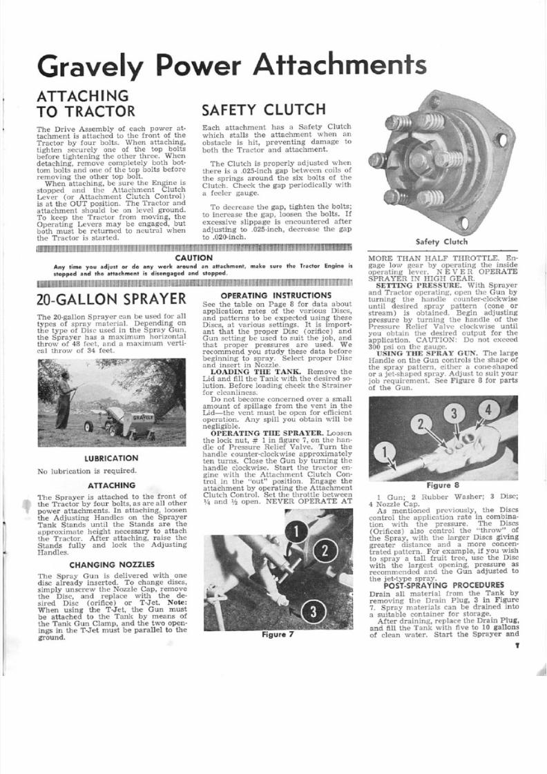
Each attachment has a Safety Clutchwhich stalls the attachment when anobstacle is hit, preventing damage toboth the Tractor and attachment.
The Clutch is properly adjusted whenthere is a .025-inch gap between coils ofthe springs around the six bolts of theClutch. Check he gap periodically wi ha feeler gauge.
To decrease the gap, tighten the bolts;to increase tile gap, loosen the bolts. Ifexcessive slippage is encountered after
adjusting to .025-inch, decrease the gapto .020-inch.
I l li J ~ ~ i j~ ~ m l l[ [ ll lm ~ i j l m l l m ~ ~ i j ij ij ~ m l ll l ll 'l ll m m r l r m ll l l l l m l l m r l l l m m l l l i j ~ i j ~ i j l J l l m l l l l l l l m m m m 1 m m ~ i j m ~ ~ i j m m ~ i j i j ~ ~ ~ l l m ~ ~ i j i j ~ i j ~ O O 1 l l l m m m ~ f f i I I ] l ] l m ~ l i I 1 1 n m m ~ m m l l m J l J f r n n ~ i j ~ ~
CAUTIONAny lime yau adju.1 er do any wark around an .tt,chmenl. make sure the Tr.clar Engine i.
slopped and the attachment is disengaged and slopped.
W ~ I I [ I [ il ll ll l m l l lm ~ ~ ~ m m m l l ll ll l m j W j l m m m l m ~ i j ~ ~ m l l! l m l [ I ~ l l lm l ll l ll ll l ~ ! l ll r l[ 1 [ l l m ~ r n m l ll l m l l [ ][ J i j ~ i jl l ll lm l ll l ll r n U l m l l m m ~ l l l ll ll il l ll ll l ll il l ij ij i jm m l m l l l[ r n i j ~ ~ ~ i ji j ll ll l ll ll m r u m m i ju l l l ll l lm f I J m l l l[ 1 I I 1
20-GA LLON SPRA YERThe 20-gaUon Sprayer can be used for alltypes of spray material. Depending onthe type of Disc used in the Spray Gun,the Sprayer has a maximum horizontalthrow of 48 feet, and a maximum verti-cal throw of 34 feet.
LUBRICATION
No lubrication is required.
ATTACHING
The Sprayer is attached to the front ofthe Tractor by four bolts, as are all otherpower attachments. In attaching, loosen
the Adjusting Handles on the SprayerTank Stands until the Stands are theapproximate height necessary to attachthe Tractor. After attaching, raise theStands fully and lock the AdjustingHandles.
CHANGING NOZZLES
The Spray Gun is delivered with onedisc already inserted. To change discs,simply unscrew the Nozzle Cap, removethe Disc, and replace with the de-sired Disc (orifice) or T-Jet. ote:When using the T-Je, the Gun mustbe attached to the Tank by means ofthe Tank GWl Clamp, and the two open-ings in the T-Jet must be parallel to theground.
O PER AT IN G IN STR UC TIO NS
ee the table on Page 8 for data aboutapplication rates of the various Discs,and patterns to be expected using theseDiscs, at various settings. It is import-ant that the proper Disc (orifice) andGun setting be used to suit the job, andthat proper pressures are used. Werecommend you study these data beforebeginning to spray. Select proper Discand insert in Nozzle.LOADING THE TA K. Remove the
Lid and fill the Tank with the desired so-
lution. Before loading check the Strainerfor cleanliness.Do not become concerned over a small
amount of spillage from the vent in theLid-s-the vent must be open for efficientoperation. Any spill you obtain will benegligible.OPERATING THE PRAYER. Loosen
the lock nut, # 1 in figure 7, on the han-dle of Pressure Relief Valve. Turn thehandle counter-clockwise approximatelyten turns. Close tile Gun by turning thehandle clockwise. Start the tractor en-gine with the Attachment Clutch Con-trol in the "out" position. Engage theattachment by operating the AttachmentClutch Control. Set the throttle between\4 and 1h open. NEVER OPERATE AT
Safety Clutch
MORE THA HALF THROTTLE. Egage low gear by operating the insidoperating lever. N EVE R OPERATESPRA YER IN HIGH GEAR.
ETTING PRE RE_ With Sprayeand Tractor operating, open the Gunturning the handle counter-clockwiseuntil desired spray pattern (conestream) is obtained. Begin adjustingpressure by turning the handle of tPressure Rcliet Valve clockwise unyou obtain the desired output for tapplication. CAUTION: Do not excee300 psi on the gauge.D ING THE PRAY GUN. The larg
Handle on the Gun controls the shapethe spray pattern, either a cone-shapedor a jet-shaped spray. Adjust to suit yojob requirement. See Pigure 8 for par
of the Gun.
1 Gun; 2 Rubber Washer; 3 Dis4 ozzle Cap.
As mentioned previously, the Dis
control the application rate in combination with the pressure. The Dis(Orifices) also control the "throw"the Spray, with the larger Discs givingreater distance and a more concentrated pattern. For example, if you wito spray a tall fruit tree, use the Diwith the largest opening, pressurerecommended and the Gun adjustedthe jet-type spray.
P OST -SPR AY IN G PR OC EDU RESDrain all material from the Tankremoving the Drain Plug, 3 in Figur7. Spray materials can be drained ina suitable container for storage.
After draining, replace the Drain Pluand fill the Tank with five to 10 gallonof clean water. Start the Sprayer an
5/13/2018 L8, 1966 Owners Manual - slidepdf.com
http://slidepdf.com/reader/full/l8-1966-owners-manual 10/28
begin spraying. Using the Gun, you ca n
clean the outside of the Sprayer and byinserting it inside the Tank, you canwash the Tank Interior thoroughly.Continue flushing, refilling if neces-
sary, until the Tank and Gun are clean.Then remove the Drain Plug again,drain, and replace.
Clean the Strainer at this time, by
removing the wing nut, I in Figure 9Then hold the Strainer, 2 in Figure 9,
under a faucet and flush it with cleanwater from the inside out.
DRAIN PUMP If IN
DANGER OF FREEZING
In cold weather-when a freeze is antici-pated-always drain the Tanl" connec-tions, and Pump.To drain the Pump, remove the Drain
Plug from U1e T·Joint, remove the clamp[rom the Pump end of the Pump-to-Tank Hose, and Hold down to drain.(Some Sprayers have the Hose replacedby a pipe and fittings. For these, removethe Drain Plug from the T-Joint at thesame location.) Loosen the lock nu t [romthe Pressure Relief Valve and turn theValve counter-clockwise 5-10 turns,Next, loosen, but do nol remoue, the
figure 9
i ,I I II I II I II I II I II I II I W l l lt I II I II I II I II W I I II I II I II I '1 1 1 I I I I m l lJ I I 1 1 1 1 1 U 1 I I II I II I II I Im l 1 1 1 1 1 1 1 1 1 1 1 1 1 1 1
CAUTION
Sprayin9 ',ompound', u,ually are pcisoncu s
Take the manufa <I<I re . ' , .ecommended, .~faly
pr'o eeelur es "' all limes, bolh in handlin9 .'nd
$pr~yin!l and in' pretectien of bY-Slanders, par-
li cul arly chi l'd r, e,n and animals. Donol allow
children 10 oper a te the Sprayer, "nd keep i't
.,nd aU sprayin9 mate,ials out of their ~"C'''S'.
: ~ ~ ~ ~ ~ m l l ll l ll l ll ~ m l l [I I I I I J m j l ll l ll l m l l l ll l l' I 'l m m m m l I m l m l l l' l il m l ll r j ! m m J ~ l l lm l l ll l ll l 'l l ll l m l [ l l i
CONDENSED SPRAY GUN DATA
(All ratings taken at maximum pressure, 300 psi)
Disc Maximum Stream Throw
Horizontal Vertical GPM
Maximum
Horizontal
Throw
Pump Caps. Loosen the bolts only unthe Cap will come out about lfs-incBoth Caps should be treated this waAfter draining is completed, replace tCaps and all connections and plugs.
HI.NTSFOREASIER
OPERATION
Be sure the apertures in the Discs a
T-Jet are kept clean. Also, be sureStrainer is kept clean. If these becomclogged, the Sprayer will not producespray from the Gun.
• After using a corrosive or abrasivspraying compound, make sure thetire Sprayer is cleaned thoroughly, boinside and out. Doing this will addthe life and satisfactory performancethe Sprayer,
• If a leak in the plumbing developtry to tigh ten sligh tly. If this doesnwork, replace the offending parts. Doovertighten the connections-use mimum pressure to set these securely.Any other malfunction of the Spraye
should be called to the attention of yoGravely dealer, who has the parts, tooand knowledge to serv ice it quickly a
efftcien By.
Angle
of
Spray
GPM
D-.2
D-4
35'
39'
.90
1.80
D-6 48' 34' 4.10 11.0' 33 3_80
T-JET: Gives fan spread of approximately 8-10', yields. 41-1. 64 GPM
depending on pressure (which can be set from 25 psi to recommended
Ll1 axirnum of 300 psi).
POWERT AKE-OFFThe Gravely Power Take-off can be usedto run any equipment which gets itspower from a belt and does not requiremore than 4.8 horsepower.
LUBRICATION
No lubrication is required.
AHACH.ING
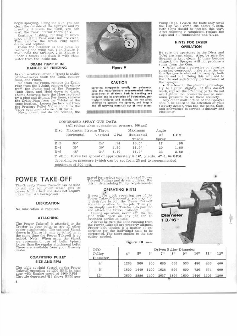
The Power Take-off is attached to theTractor by four bolts, as are all otherpower attachments. The optional Stand,shown in Figure 10,. may be bolted on atthe same time the Power Take-oft is at-tached. Note: W11en using the Stand,we recommend use of bolts 1f4-inchlonger than the regular attachment bolts.These are available from your Gravelydealer.
COMPUTING PULLEY
SIZE AND RPM
The table at right (based on the PowerTake-off operating at 1200 RPM in highgear with Engine speed at 2400 RPM-Throttle depressed ¥.J) shows RPM gen-
8
24'
30'
.94
1.90
10.5'
11.0'
erated for various combinations of PowerTake-off Pulleys and driven pulleys. Usethis in determining Pulley requirements.
OPERATING HINTS,~
If you have a job requiring use of thePower 'I'ake-off Ir-equenfly, you may findit desirable to bolt the Power Take-offStand in position [or the job. Then youcan simply run the Tractor into positionand attach the Power Take-off.
During operation, never rll'n the En-gine wide open on any job for anextended p_eriod of time.
Always be sure the belts running fromthe Power Take-off are properly aligned,Proper belt tension is a matter of ex-perience for the individual task to beperformed. The same applies to the sizepulley needed.
iFigu.re 10 _
17
20
t .D'iameter
13/16 1
'I
ETO Driven Pulley Diameter
Pulley 4" 5" 6" 7" 8" 9" 10" 11" 12
Diameter
4" 1200 960 800 685 600 533 480 436 40
6" 1800 1440 1200 1028 900 800 720 654 60
12" 3600 2880 2400 2057 1800 1600 1440 1309 120
'"

5/13/2018 L8, 1966 Owners Manual - slidepdf.com
http://slidepdf.com/reader/full/l8-1966-owners-manual 11/28
SICKLE MOWERThe Sickle Mower is a rugged, dependa-ble mower that makes the toughest weedand brush cutting easy. Swivel actionallows the Blade to follow the groundcontour to insure a clean cut.Blades longer than the standard 42
inches are available from your Gravelydealer. Blades are provided with three-
inch sections for heavy mowing and two-inch sections for finer mowing.Using the Dual Wheels or Extension
Axles, the Sickle Mower can cut slopesas steep as 60 per cent. See Pages 5 and 6.
LUBRICATIONCheck the Drive Assembly oil level everyfour hours of operation by removing theOil Level Plug, 1 in Figure 11. If oilruns out, the oil level is all right; if not,
oi! must be added.To add oil, remove the Oil Filler Plug,
2 in Figure 11 and pour oil through theOil Filler Hole until oil begins to runout the Oil Level Hole. Replace bothPlugs before mowing.Use SAE 140 in lhe Drive Assembly.To lubricate the Universal Joint, re-
move the Grease Plug, 3 in Figure 11,
and fill about half-full with GeneralPurpose Grease.Because the Universal Joint needs
lubrication only occasionally, you may. pre er this method: with the Mower de-tached from the Tractor, remove theSafety Clutch and tour bol s, 4 in Figure11 which hold the lower column to theUniversal Housing and slip the Housingpartly off. Then apply General PurposeGrease generously to the Universal Joint(coal it all over with one to I'll inches ofGeneral Purpose Grease). Reassembleall parts, making sure you tighten firmlythe large nu which holds the Safety
Clutch.
I
e
ADJUSTMENTS
To insure satisfactory performance,perform the following adjustments asrequired:BOLT. Although the Sickle Mower
is bui.lt and balanced carefully, it is stillsubject to some vibration. Periodicallylighten all nuts and bolts, doing this atmore frequent intervals when doinghe~l\ry cutting. Note: The Gravely
Triple-Purpose Wrench, available fromyour Gravely dealer is required for theActuating Lever ut.CLIP _ The Clips which hold the
Knife to the Guide Bar should be ad-justed frequently to prevent cut matterfrom "bunching" and causing improperfeed-off. When in proper adjustmentthe Clips should allow the Knife to sJid~back and [or h easily (with the pressureof a finger and thumb). The Clipsshould hold the Knife in firm contactwith the Shear Plates, but should notcause binding. To adjust knock theClips down gradually wi h' gentle tapsfrom a light hammer.
WIVEL A TION. To increase swivelaction (allowing the M wer to followthe contour of the ground), loosen the
bolts, 6 in Figure 11. When these bol tsare tightened firmly, the Mower is heldin a rigid position. The bolts should betight enough so the Guide Bar will holdits position until lowered, but looseenough for the Guide Bar to follow thecontour of the ground.G ARD. Always keep the Guards
7 in Figure 11, in alignment by tappingthese with a light hammer until theKnife Sections lie flat on the ShearPlates of the Guards. Keep the GuardBolts lightened securely.
CARE OF THE KNIFE
For best performance, keep the KnifeSections sharp, To remove the Knife forsharpening, remove the Kn iIe BracketScrews, 5 in Figure 11, and slip the
Knife out either side. Grind the Knife
Figure 11
Sickle Mower.....-+
Sections along the same bevel as grouoriginally. When. replacing the Knmake sure the Knife Bracket Screwstightened firmly.Note: It is good practice always
have an extra Knife, already sharpenewhich you can put on the Mower whneeded. This way you can always havesharpened Knife in reserve. The GraveSickle Grinder (see Page 10) can be pchased from your Gravely dealer, or
will sharpen your Knife for a smbarge,
No lubrication is required forKnife while in operation, as juices frweeds and grass will furnish sufficilubrication. However, to prevent ruWIpe the Knife and Guide Bar withthin coat of light oil after operatinWhen the Mower is to be stored forperiod of time, clean it thoroughlyapply General Purpose Grease to allpainted parts.
OPERATING HINTS
Always mow at a normal walking spwith the Tractor in low gear. Excessispeed will exaggerate the Mower vib11On, causing nuts and bolts to beco
loose much faster than normal.• Ii excessive vibration is encountere
check to see if the Wearing Tip (onend of the Actuating Lever) is wornmissing, or if the Bracket is worn badif so, your Gravely deaJer can replathese parts for you,• If cut grass or weeds begin colle
ing on the Mower instead of feeding-properly, check the alignment ofGuards and Knife Sections, as wellsharpness of the Knife Sections...If this does not correct the impr
er feed-off, make sure one end ofMower is not dragging up already-cmaterial. This is the result of taking
small a "bite."" Another cause of improper feed-
is a rusty or gummy Mower. Alwa
keep itclean.• Finally, the improper feed-off m
be caused by improper adjustment of
Safety Clutch. See page 7.
, I I ~ I I IU 1 I I I I m l l li li m l ll li ll il li lm m 1 l l lm l ll ll m l l ll ll ll ll ll l~ 1 I t lw l l l ,m l ll ll l 1 I l lm l ll 1 1
CAUTION
Never altempt to dear the Mowe., or m
any adjustment whatsoever, unless the att
ment is out of gear and stopped, and
Ir -a e+oe Eng ine is .topped.
• Nev,er han dIe the aifachment by an Y cul
surface. Keel' hands away from Kn ife
tiona. Gr.sp the Mower by its Drive Col
and ether non-cutting surfaees to carry
• Try to keep clear of rocks and debris,
th ese will damage the culting surfaces.

5/13/2018 L8, 1966 Owners Manual - slidepdf.com
http://slidepdf.com/reader/full/l8-1966-owners-manual 12/28
SICKLE MOWER (continued)
SKIDS
Skids which £i t under the Guide Bar areavailable from your Gravely dealer. Formost mowing, these Skids are not neces-sary; however, you may want these forcertain jobs, such as mowing pastures inwhich you wish the grass to grow andonly the tall weeds to be cut.
Your Gravely dealer will provide youwith instructions for Install ing the Skidson your Sickle Mower.
SICKLE GRINDER
The Gravely Sickle Grinder is a neces-sity if you do much mowing with theSIckle Mower. The Grinder comesequipped with a three-inch cone cor-rectly beveled to sharpen properly thethree-inch Sickle Knives. Two-inch conesare available for two-inch Knives.
In ordering, specify the size Knives
your Sickle Mower has.Instructions are packed with the Sickle
Grinder.
50 -INCH ROTARY MOWER
LUBRICATION
Check the oil level in the Gear Housingevery four hours of operation, by re-moving the Oil Level Plug, 1 in Figure12. If oil runs out, the oil level is allright; if not, oil must be added.
To add oil, remove the Oil Filler Plugapproximate location shown by 2 i~
Figure 12, and pour oil through the OilFiller Hole. . Stop when oil begins torun out the ail Level Hole. Replace botbplugs before mowing.
Use SAE 140 in the Gear Housing.
Use General Purpose Grease every 10bours in the grease fittings on the CasterBrackets, Caster Wheels, and SwivelCasting 3 in Figure 12.
Use General Purpose Grease every 10hours in the grease fitting on eachSpindle Assembly. Note: The SpindleAssembly grease fitting is vented to makeit impossible to over-lubricate the Spin-dle Assembly. While greasing, if youobserve grease coming out the vent thismeans simply that the Spindle Assem-
bly is loaded to capacity with grease.
10
The 50·Inch Rotary Mower is designed[or fast and efficient mowing of largelawns. It is not designed to mow taJIweeds, undergrowth, and other heavyplant matter. If these are on yourgrounds, we suggest you see yourGravely dealer for a free demonstrationof attachments designed or this type cut-ting, such as the 30-inch Rotary Mower.
CUTTING HEIGHT
ADJUSTMENT
Cutting height adjustment is made atthe Spindle Assemblies on the SpindleShafts.Each of the three Blades can be ad-
justed to cut from one to four inchesCram the ground. At delivery the cut-ting height is set at :P h inches 'from the
ground. To adjust each Blade:
1. Remove the Spindle Cover (cylindrical cover on top of the BGuard) by removing the sheet mescrews which hold it to the Deck.2. Remove the cotter key from
end of the Hight Adjustment Pin, 1
Figure 13. On the center and riBlades (center and right as you staat the Handles) the cotter ltey andare accessible upon removal of the Sdle Covel'S. However, to gain accessthe left Blade cotter key and Pin, reunder the left Belt Guard. An alternamethod is to remove the entire left BGuard (which includes the SpinCover) by unscrewing the mach
screws which hold it to the Deck.3. Insert a screwdriver or sirn ilar
in the large hole at the top of tile SpinShaft. Using the screwdriver, liftslightly on the Shaft and remove the
4. There are six holes in the Sh(exclusive of the large hole in whthe screwdriver was placed) which relate the cutting heigh t. The topmost hsets the cutting height at 1% inches fthe ground, the next at two inches frthe ground, and so on in lfl-inch inments to a maximum cutting height
four inches. Line up the hole cosponding to the desired CUtti11g hei
with the holes in tile Shaft Housingin Figur 13, and insert the Heightjustment Pin into these. The.1 insertcotter key in the end of the Pin.5. Replace the Spindle Covers (and
left Belt Guard, if it has been remove
CUTTING PLANE
ADJUSTMENT
'The Caster Wheels keep the Mowerhorizontal plane parallel to the grouWhen the Caster Wheels are adjusproperly and the three Blades areat the same cutting height, the Mocu smoothly and unlformly throu
out its swath.
During operation, should you nothe Mower cutting closer on one sidits swath than on the other, or ifSkids mark the ground with a narrtrench-like depression, this would icate the Caster Wheels are out of
justment.Adjust the Caster Wheels by the
large washers on the Caster Bracket.raise the Mower, place two, three,four washers at the bottom of
Bracket; conversely, to lower the Mowplace two, three, or all four washersthe top of the Bracket. If one Smarks the lawn, raise the Mower byCaster Wheel nearer it; if both Smark the lawn raise the Mower by b
Caster Wheels.
Figure 13

5/13/2018 L8, 1966 Owners Manual - slidepdf.com
http://slidepdf.com/reader/full/l8-1966-owners-manual 13/28
To rearrange the washer combination,place a block under the Skid nearer theCaster with which you are working.Then remove the bolt which secures theCaster Fork to the Caster Bracket. Re-move the Caster Wheel and Fork andrearrange the washers as desired. Thenreassemble the entire Caster Assembly
BEtTS
The Mower has two Belts: the right Belt(right, as you stand at the Handles),which drives the center and right Blades,and the left Belt, which drl ves the leftBlade. Proper adjustment of the Beltsis vital-if too tight, the Belts will wearexcessively; if too loose, the Belts willslip, causing the Mower to skip over areaswithin its swath. Also, if the Belts arenot in proper adjustment, the Bearingsand Belts will run hotter than normal,
BELT ADJ STl\IENT. The Belts arein proper adjustment when the Moweris delivered. Loosening is seldom re-quired, except when replacing a Belt.However, from time to time you willneed to tighten the Belts; this is indi-cated by the Mower skipping over areas
within its swathThe left Belt is adjusted at the leftSpindle Assembly, access to which isgained by removing the machine screwswhich hold the left Belt Guard to theDeck. The right Belt can be adjusted ateither the ri,ght or center Spindle Assem-blY, access to which is gained by remov-ing the machine screws which hold thecenter and right Belt Guards to the Deck,
We recommend that adjustment of theright Belt be made at the right SpindleAssem bly inifia l l y ; only if a ddi tiori O Il ad-justment is needed should you adjust atthe center Spindle Assembly
To tC: In adjusting the Belts it ispossible to pull a Spindle Assembly farenough from its proper position to causeits Blade to strike the adjacent Bladewhile mowing. When you have adjustedthe Belts, always rotate tile Blades byhand to make sure there is no Blade in -terferen cc and to ins u re there is Su tfi-dent overlap to keep [rom missing areas,especially on turns.
The procedure for tightening eachBelt is the same-the Spindle Assemblyis moved Irom the Main Drive Pulleyas follows (Refer to Figure 14 [or partsidenti.fication) :
l. Loosen the four nuts which holdthe Spindle Assembly and Dust Shieldto the Deck. It is not necessary to holdthe bolts onto which these are screwed,as they are locked to the underside of
the Deck.
Adju sting Nul AAdju stin g Nut B rncket BAdju stm .en t Lock Nu t C
A CB
left
2. Back off the Adjustment Lock Nutseveral turns from the Adjusting NutBracket.
3. Tighten the Adjusting Nut againstthe Adjusting Bracket until proper ten-sion has been applied to the Belt. Whenthe Belt is in proper adjustment, by ap-plying moderate pressure at its mid-point, you should be able to deflect theBelt approximately %"inch.4. Holding the Adjusting Nut firmly
against the Adjusting Nut Bracket,tighten the Adjustment Lock Nut se·curely against the Bracket.5. Tighten firmly the four nuts which
hold the Spindle Assembly and DustShield to the Deck.In loosening a Belt, the Spindle As-
sembly is moved toward the Main DrivePulley as follows (Refer to Figure 14 forparts iden ti.fica tion) :
1. Loosen the four nuts securing theSpindle Assembly and Dust Shield.
2. Back of! the Adjusting Nut severalturns [rom the Adjusting Nut Bracket.3. Back off the Adjustment Lock Nut
from. the Adjusting Nut Bracket untilproper Belt tension is reached,4. Holding the Adjustment Lock Nut
firmly against the Adjusting Nut Brack-et, tighten the Adjusting Nut firmlyagainst the Bracket.
5. Tighten firmly the four bolts secur-ing the Spindle Assembly and DustShield to the DeclcBELT REPLAGEll'IENT. After all pos-
sible Belt adjustment has been made, ii
the Mower continues to skip over areaswithin its swath, replacement of theappropriate Belt is indicated.To replace the right Belt (right, as
you stand at the Handles):1. Following "Belt Adjustment" pro-
cedures, remove the center and rightBelt Guards and move the center andright Spindle Assemblies toward theMain Drive Pulley as far as possible.
F.igul·e 14
2. Remove the right Drive MSupport Sleeve, 1 in Figure 15. Tothis, elevate the Mower sufficientlyenable you to hold the Sleeve Boltthe underside of the Deck. Removenut [rom the Sleeve Bolt, tap thefree of the Mower,and removeSleeve.
3. Slip the Belt from the Main DPulley, Center Spindle Pulley, and r
Spindle Pulley, and remove thefrom the Mower.4. Place the new Belt on the Pulle
Replace the right Drive Mount SuppSleeve.
5. Adjust the Belt. When positionproperly on the Pulleys and ill proadjustment, there should be appromately l/32·inch between the top ofBelt and the top of the Pulley fianges6. Replace the Center and Right
Guards.To replace the left Belt (lett, as
stand at the Handles):1. Remove the left, center, and r
Belt Guards.2. To provide clearance for remov
the left Belt, the right Belt mustloosened enough to slip it from
groove in the Main Drive Pulley.mally, the right Spindle Assemblybe moved far enough forward towthe Main Drive Pulley to make thissible. Do not move the center SpinAssembly unless absolutely necessaDo not remove the right Drive MoSupport Sleeve.
3. Move the left Spindle Assemblyfar forward as possible toward the MDrive Pulley.
4. Remove the left Drive Mountport Sleeve, 2 in Figure 15.5. Slip the Belt from the left Spin
Pulley and Main Drive Pulley, reming it from the Mower.6. Place the new Belt on the Pull
and replace the left Drive Mountport Sleeve.
7. Adjust the Belt. Be sure thereapproximately 1/32-inch clearancetween the top of the Belt and the topthe Pulley !langes.8. Make sure the right Belt has b
replaced on the Main Drive Pulleyis in proper adjustment before replacithe three Belt Guards.
BLADE SHARPEN ING
To sharpen a Blade, remove it fromMower and use the original cutting edas your guide. After sharpening, testproper balance by inserting a scrdriver and holding the screwdriverallel to the ground. If one side ofBlade dips noticeably, that side isheavy and should be ground further.
OPERATION
We recommend that you mow socut grass is discharged (out the leftof the Mower) onto the lawn awhich have not been cut.
m l l~ ~ ~ ~ l l ll ll lm l ll ll ll m l l l ll lm l ll lm I J I IJ I I II I I [ I~ ~ m 1 . 1 1 1 1 1 1 1 1 1 1 1 1 1 1 1 1 , ll ll lm l
CAUTION
'Never pul your hand. or feel under thewhile II", MQwer is rU,,"i·,,!l', or for an int
aher ,he Mow"r has :b~M di.e"9·0ged.sure 0 , 1 1 BI.,d ". h . . ve , topped bd,,,re attempt
any rep li ro ' .ad.iustmenl Ie Ihe Mow~,rIh"t the .nachmenl i, disengaged .,nd
Engi,"" stopped.. -
! 1 : I ! 1 ! ll lm l m l ~ ~ l Il J l jl jI J m l lm l l~ m m l ll ll ll lm m l " l" ' I[ l ll ll m m l l! l ll m m l m m l ll ! ll ll ll [ ll lm l l

5/13/2018 L8, 1966 Owners Manual - slidepdf.com
http://slidepdf.com/reader/full/l8-1966-owners-manual 14/28
ATTACHMENTS US ING 30-INCH ROTARY MOWER DR IVE
V.ERSATILE. The 30·in,~h R Q . •
lary Mower handiles .ough
and smoolh lawns wilh cquQI
ease .... and itsDrive pew-
ers fQ~' ether al' l. <hmenl • .
Figure 16
In addition La the 30-inch Rotary Mowe r ,four other power attachments use theDrive Assembly shown in Figure 16.These are the Leaf Mulcher, Leaf-Away,Chain Saw, and Circular Saw.
LUBRICATION
I ,
Check the Gear Housing oil level everyfour hours of operation by removing theOil Level Plug, I in Figure 16. If oilruns out, the oil level is all right; if nol,oil must be added.
To add oil, remove lhe Oil FiJler Plug,2 in Figure 16, and paul" thrcugh the Oil
Filler Hole until oil begins to run cutthe Oil Level Hole. Replace both Plugsbefore operating.
Use SAE 140 in the Gear Housing.
Use General Purpose Grease oeca-sionally in the grease fittings of theSwivel Casting.
SWIVEL ACTION
A:OJUSTMENIT
Swivel action of the Drive Assembly isregulated by the Swivel Adjustment Boltand Nut, 3 in Figure 16,. Loosening theAdjustment Nut increases swivel action;tightening it decreases swivel action.When using the 30·inch Rotary Mower,
Leaf Mulcher, and Leaf-Away, thereshould be sufficient swivel action toallow the attachment to follow theground contour with its own weight.When using the Chain or Circular Saw,loosen the Adjustment Nut, turn theDrive Assembly to the desired angle,and tighten the Nut firmly.
30-1NCH
ROTARY MOWER
To attach the 30·inch Rotary Mower tothe Model 106 Drive Assembly, detachthe Drive Assembly from the Tractorand turn it upside down so the Oil Filler
Plug is on the bottom.
Next, set the Mower Hood in placewith the Rear Fender (the taller of thetwo Fenders) facing the rear of theDri ve Assembly.
Place a bolt and plain lh·inch washerthrough each ct the six holes in theHood and Gear Housing flange, with the
bolt heads on the under side of the Hood.Place a lock washer and nut on the endof each bolt showing through the GearHousing flange and tighten each nutsecurely,
Place the Cellars and Blade onto theRotor Shaft in any order you wish. (See.,Cu tting Heigh t Adj ustmen t," below.)Be sure the counter-bored sides of theCollars face the Blade. Tighten the nuton the end of the Rolor Shaft securely,Note: The G r a vel y Triple-PurposeWrench, available from you!" Gravelydealer, is required for the nut on theend of the Rotor Shaft. It also must beused for tile Actuating Lever Nut onthe Sickle Mower, and Tine Shaft Nuton the Rotary Cui tivator.
CUTTING HE.IGHi
ADJUSTMENT
Cu lting height is adjusted by the Collarson the Rolor Shaft, The closer the Bladeis to the Gear Housing, the higher thecut, and vice versa. Vary the cornbina-iton of Collars as you desire, alwaysmaking sure the counter-bored sides ofthe Collars face the Blades.
B L ADE SH 'A R P EN :lN G
Use a file Dr grindstone to sharpen theBlade. Try to follow the same bevel as
the originally-sharpened cutting edge,although the precise degree of bevel isnot critical.
F ENDE R AOJUSTM ENT
When mowing short weeds and lawns,the Front Fender (the smaller Fender)must be on front of the Mower Hood,and the Rear Fender (the larger Fen-del') on the rear.
However, when mowing high, heavybrush, or thick, tough grass of consider-able height, better mowing results willbe obtained by removing the Front Fen-del', and replacing it with the optionalChain Guard. See below.
CHAIN GUARD
When the Front Fender is removed, it'must always be replaced with tile op-tional Chain Guard. Attached to theMower by bolts in place of the Front
Chain Guard
Fender, the chains reduce the veof materials that may be thrown ois available from your Gravely de
1 1 1 1 ' l l ll lm l 'l : J I I .I ,I I~ l ll ll m ! ll m J ~ m J I J m 1 , 1 1 1 1 1 1 1 1 1 1 1 1 1 1 1 1 1 1 1 1 1 1 1 1 1 1 1 1 1 11 1 ' l l l l l l l l l l l . l l l l ll l m
CAUTION
Never p~·1 y"ur han 0 ; 1 , or f.ee' en der l '
whihJ the Mower is runni,ngi or , for t!n
.fler th. MQwe, is, s'hul "If. M .~e
Blade, has sl,opped <omp!elaly, w
Engi ne olf and the Mower di:,engaged,
aU'emptin.g ~ny.diu.lm"'nt Or ra;I'air
Mcw,e,r~
.. Never epcrate the Mower un Iess th
'Fe,nde' oropli'onal Chain G~ard is
front of the Mowe,r, and Ihe Rear h
on the feu of the Mower.
• When uein 9' the JO·inchRolary
neve, shift Ihe In side O;per.li ng lever
from high 10 low, .Alw.ys pause mom
in no utrail, giv'ing Ihe Slade " chance
dow"n"t~r.'lIy,lhu, avoiding Ihe sever
ling ~;,c;tion,hom ~, :sudden shi 'Ft ir tto lo
I I ll m m m ~ m l l ll l ll l ll ! II J ! m l l ll l ll l ll m m l m l r l l l m I I J l J r J I J I I I J l m l l I l ll m l l l l ll l ll l .l m l ~ m l l m ! ~ ! m l l ll l ll l
LEAF MU LC HER
Attach the Lea! Mulcher to theRotary Mower as follows:
1. Remove both the Front andFenders. Bolt the Rear Fenderfront of U1e Mower Hood.
2. Attach the Leaf Mulcherreal" of the Mower Hood, in the pnormally occupied by the Rear F
To operate the Leaf Mulcher, pthe same as you would in mowing.
mal walking speed is usually adeto do a good job, although whenare wet or packed down, you mayto go OVer the area twice.
LEAF -AWAYInstructions for assembling anding are packed with the Leaf-Away
Note: The Leaf-Away can beonly with 30·incll Rotary MowersBlades rotate clockwise (Model58-A, 106, and 185).
MUFFLER ADJUSTMENT
Remove the Muffler, insert the all-
Nipple and Elbow, and re-attachMuffler. Direct the Mulfier so thaust will hit the asbestos panelPouch, When lhe Leaf·Away is ning used, the Nipple and Elbow mremoved, and the Muffler placedTractor in the normal manner.
EMPTYING POUCH
To empty the Pouch, simply unsnaPouch from the Chute, unhook ithe Pouch Support, and unzip. Coare easily shaken out.
Note: For use in large areas,as college grounds, we recommendchase of additional Pouches. Sfilled pouches may be taken in a
to where the lea ves are to be burn

5/13/2018 L8, 1966 Owners Manual - slidepdf.com
http://slidepdf.com/reader/full/l8-1966-owners-manual 15/28
OPERATING HINTS
Q Operate the Leaf-Away with the
Tractor in high gear at all times.• Stoppage caused by leaves and de-
bris blocking the Chute is detected bycollapse of the Pouch. To correc , keepthe Blowers operating at high speed andwork the Chute Cleaner Poker with avertical motion into the Chute.
• Although the Leaf-Away will func-tion effectively in most cases with onlyone Mower Blade Blower, we recom-mend use of both Blowers, especiallywhere leaves and debris have a highmoisture content. Also, we r commendyou clean your lawn often enough toprevent leaves from becoming packeddown by heavy rain or SI10W, as leavesin this condition increase th chance ofChute clogging.
CHA IN SAWBefore attaching the Chain Saw to theDrive Assembly, make sure you havethe proper Chain Saw Bracket for your
Drive Assembly. Drive Assembly Mod-els 52 through 58, having a Gear Hous-ing diameter of 2% , inches, require theChain Saw Bracket, Part Number CS-IOI.Drive Assembly Models 58-A and 185,having a Gear Housing diameter of 3 Y 4inches, require the Chain aw Bracket,Part Number CS-IOI-L A ConvertingCollar, Part Number CS-331, may bepurchased from your G ra vely dealer toadapt he Chain Saw Bracket CS-IOl-lfor use with Drive Assembly Models 52through 58.
ATTACHING TO
DRIVE ASSEMBLY
Attach the Chain Saw to the Drive As-sembly as follows:
L Remove the nut and Collars fromthe Rotor Shaft.2. Loosen the Bracket Clamp boll, 1
in Figure 17, until the Bracket, 2 inFigure 17, will slip onto the Gear Hous-ing (it may be necessary to wedge theBracket to make it Ilt). Line the loweredge of the Bracket even with the loweredge of the Housing-not with the fixedCollar. Tighten the Bracket Clamp Bollto lock the Bracket in place.
3 _ Loosen the Swivel Adjustment Bolt(on the Drive Assembly) and rota e theBracket until the Guide Bar, 3 in Figure17, points straight up. Then tigh ten theSwivel Adjustment Bolt.4. Loosen the Clamp Bolts (which
hold the Bracket together) enough toallow the Guide Bar to slide back and
forth easily. Put the Chain on the GuideBar, bringing it through the Bracket.
5 _ Slip the Ih-inch Collar onto theRotor Shaft, with the counter-bored sidetoward the end of the Shaft. Slip theSprocket onto the Shaft and put theChain around the Sprocket. ote: OnDrive Assemblies 58, 58-A, and 185, whenviewed from the end of the shaft, theSprocket revolves counter-clockwise; onthe other Drive Assemblies, the Sprocketrevolves clockwise, Be sure the cuttingteeth move in the same direction as theSprocket,
6 _ Place the lf4-inc11 and 7fs-inch Col-lars on the Shatt, making sure the ccun-ter-bored sides face the Sprocket. Put theflat washer on the Shaft and tighten thenut firmly.
CHAIN ADJUSTMENT
Turn the Chain Adjusting Screw, ap-proximate location on other side ofGuide shown by 4 in Figure 17, clock-wise to increase Chain tension. Whenthe Chain is under proper tension, it willbe slightly loose on the Guide Bar, butnot loose enough to permit it to comeout 0 its slot when grasped firmly andpulled away strongly from the Guide
Bar. Excessive tension will cause theChain to "burn" the Guide Bar.
ANGULAR ADJUSTMENT
To change the position of the Chainaw in relation to the Gear Housing,
loosen the Bracket Clamp Boll and turnthe Sa w to the desired position, tilentighten he Bracket Clamp Boll.
To rotate the Drive Assembly, loosenthe Swivel Adjustment Nut and movethe Drive Assembly to the desired posi-tion; then tighten the Nut,
Figure 17
OPERATING HINTS
Best results can be obtained with theChain Saw if you:
• Always swing the Saw sidewaysinto the tree, Jetting it. "feed' itself nat-urally by applying only light pressureto the Tractor Handles. Never braceyourself against. the Handles to force theSaw into the tree faster than it normallywould feed itself. To do. so will causeexcessive wear of the Chain and GuidBar, resulting in unsatisfactory operationand a major repair bi ll.
• Do not cut trees flush with theground, as this allows dirt to mix with
the lubricating oil, forming an abrasivewhich quickly will wear the Chain andGuide Bar. If you have a large standof timber to cut ftush with the ground,we recommend you fell the tr es a fewinches from the ground with the ChainSaw, and then use the inexpensive Cir-cular Saw to cut o·ff the small stumps.
GAUGING AND
SHARPENING
Proper setting of the Depth Gauges,small projections that control the depthof bite of the Saw, is essential to suc-cessful operation. The Gauges are [Jotset at the factory; these must be set inthe field. A "Gauge-it" tool is furnished
with ach Chain Saw; follow the accomparrying directions to set the DeptGauges properly.
Use the sharpening set, provided wiyour Saw at no charge, to sharpen tChain Saw.
LUBRICATION
The Chain Saw has a separate OilinSystem which is attached to the Tracto
by brackets and clips.Ordinary motor oil-new or used-
may be used in the Oiling System.operate, simply depress the thumb levon the can. Use oil liberally durinoperation.To disconnect, detach the rubber tub
Irnm the copper pipe. The tank acopper pipe may be lefl on the Tractoif desired.
CIRCULAR SAWAttach the 18-inch Circular Saw a tDrive Assembly as follows:
1. Remove the Collars and nut f~)the Rotor Shaft.
2 _ Place the %-inch and Jh-inch Clars onto the Shaft with the counterbored sides facing the end of the Sha
Put the Circular Saw on the Shalt, anthen the J , t , . -inch Collar, with the couter-bored side facing the Saw. Tightetile 11U securely. [ote: Cutting edgor the Saw teeth must face in the diretion of Shaft rotation. See "Attachingto Drive Assembly" under Chain Sainstructions to determine the directionof Sha t rotation,
OPERATING HINTS
Feed the Circular Saw from the sijust as you would feed the Chain Sawby exerting slight pressure on the 'I'ralor Handles. Do not force the Saw;
it "eat" into the tree gradually.• The Circular Saw is most effectiv
for clearing land of saplings, sproutsand other small growth. We do not reommend the Circular Saw for fellinlarge trees; the Chain Saw does this beter and faster .
• Drive the Tractor slowly, swingingthe Saw slightly from side to sideclear a wider path. Experience will dtate when iL is best to stop your forwardmotion and concentrate on a sproutsapling too large to "drive through."
• Be careful not to run the Saw inthe ground or against rocks.
OPTIONAL SAW GUARD
An optional Circular Saw Guard, whicattaches to. the Gear Housing by a splring, is available from your Gravelydealer. When ordering, give the modnumber of your Drive Assembly.
SHARPENING THE SAW
We do not recommend field sharpening.Have this done by someone specializingin circular saw sharpening, or by youGravely dealer.
STORAGE
When the Circular Saw is to be storefor several days or longer, we recommend you coat it heavily with GeneraPurpose Grease.

5/13/2018 L8, 1966 Owners Manual - slidepdf.com
http://slidepdf.com/reader/full/l8-1966-owners-manual 16/28
30-1NCH R E E L M O W E RThe 30·inch Reel Mower gives a smoothand uniform cut every time. For thelarger mowing jobs, 25·inch Gang Unitsmay be attached to beth sides to providea 75-inch swath
WBRICATION
Check the Gear Housing oil level everyfour hours of operation by removing theOil Level Plug, I in Figure 18. If oilruns out, the oil level is all right; if not,oil must be added.
To add oil, remove the Oil Filler Plug,2 in Figure 18, and pour through theOil Filler Hole until oil begins to runout the Oil Level Hole (too much oilwill cause over-heating and consequentgear damage). Replace both Plugs be -
fore resuming mowing
Figure 18
SAE 140 is recommended.Change oil in the Gear Housing O Il
least annually. To drain, remove theentire Strut Casting, 3 in Figure 18; reoplace after the oil has drained. Add oil
as instructed above.
Use General Purpose Grease occasion-ally in the grease fittings on the SwivelCasting, 4 in Figure 18, and as requiredin the grease fittings for the Reel Bear-ings, arrow in Figure 19. It is importantto lubricate properly the Reel Bearings,as the grease forms a water seal aroundeach Bearing, preventing rust. Use Gcn
eral Purpose Grease as required in thegrease fittings on the Roller Bar.
CUTTING HEIGHT
ADJUSTMENT
Turn the Height Adjusting Screw, ;) illFigure 18, clockwise to raise the cuttingheigh t; turn it cou nter-clockw ise to lowerthe cutting height.
REVERSE LAPPING
OF REEL
The Mower has a special reverse whichpermits lapping the Reel against theBed lQ}ife, elimi.nating in some casesgrinding the Reel. The Reel should belapped any time the adjustment of the
1.
Reel against the Bed Knife is changedradically. To lap the Reel:L Loosen the bolt on the front of the
Gear Housing, 6 in Figure 18.2. Slowly roll the Reel back and Iorth
with one hand, pushing the bolt to the
opposite side of the Gear Housing withthe other. This engages the reverse;when fuily engaged, tighten the bolt.3. With the Mower running at normal
speed, carefully use a paint brush toapply a eO-grit lapping compound to theReel. Allow the Reel to lap in reverseun Iiit rna kes good can ta ct with th eBed Knife Bar along ilsentire length.To put the Reel back into forward, use
the above procedure, except push thebolt to the right and lock by tightening.
Figure 19
RESt ADJUSTMENT
The Reel must be adjusted properly forthe Mower to do a good job.To test Reel adjustment, place a sheet0 , paper between the Reel and Bed
Knife Bar and turn the Reel by hand.Perform this test at several points along
the Bar.II the paper is cut cleanly each time,
the Reel is in proper adjustment. If not,the adjustment is too loose and must becorrected by moving the Reel closer tothe Bed Knife Bar. Note: If the Reelcan tacts the Bar (thi swill seldom oc-cur), the adjustment is too tight andmust be corrected by moving the Reel
away from the Bar.
The Reel is adjusted by the Adment Lock Nut, 1 in Figure 20,the Reel Adjusting Bolt, 2 . in FigureTo move the Reel closer to theloosen the Adjustment Lock Nutturn the Reel Adjusting Bolt couclockwise; to move it from the Bar,the Reel Adjusting Bolt clockwise.
Adjustment can be made at eitherof the Reel. If, for example, facingReel you find the paper is not cut cleon the right side, loosen the AdjustmLock Nut on the right side and turnReel Adjusting Bolt counter-clockwiThen loosen the Adjustment Lock011 the left side and turn the leftAdjusting Bolt clockwise slightly.Repeat if necessary. Tighten the Adment Loci, Nuts to hold the adjustm
BELTS
Power is transmitted from theHousing to the Reel by means of a Vat each end of the ReeL
ADJUSTi\1E T. Both Belts arproper adjustment when moderatesure applied to the mid-point ofBelt will deflect it approximatelyinch.
To tighten a Belt, loosen the Beltjusting Nut, 3 in Figure 20, andthe Belt Adjusting Bolt 4 in Figureclockwise. To loosen, tu~·n lhe AdjusBolt counter-clockwise. After properjustment IS reached Llghten the Ading Nut.
If the Adjusting Boll has been tuclockwise as far as possible and thedoes not tighten, the Belt shouldreplaced.
lNTALLATION. To install aBelt, turn the Height Adjusting Suntil it releases the Reel Assembly
the Gear Housing Strut. Raise the Mslightly and swing the Reel towardTractor until the Belts are loose onPulleys. Remove tile old Belt and repwith the new one. With the new Beplace, return the Reel Assembly tonormal position, replace the Heightj L!sting Screw, and ad] ust the Mowthe proper cutting height.
Mal~e sure the newly-installed Bin proper adjustment.

5/13/2018 L8, 1966 Owners Manual - slidepdf.com
http://slidepdf.com/reader/full/l8-1966-owners-manual 17/28
25-1 NCH
G A N G U N I T S
The first step in attaching the 25-inchGang Units to the 30-inch Reel Mower isto attach the Power Take-off to theSwivel Casting (of the Drive Assembly)as shown in Figure 21.
Figure 21
Next, a Belt for each Gang Unit mustbe attached to the Power Take-off as
follows:
1. Remove the Belts from the 30-inchReel Mower, following procedures out-
lined above.
2. Loosen the set screws and removethe Outer Drive Pulley, 1 in Figure 22.
3. Loosen the Bearing Cap Screw, 2in Figure 22, and pull the Outer CrossShaft, 3 in Figure 22, out as far as pos-sible so there is room to insert the InnerWing Drive Pulley and Belt in 0 the
opening, 4 in Figw'e 22.4. Replace the Outer Cross Shaft, en-
gaging it with the Inner Drive Pulleyand tightening the set screw 011 thisPulley. Replace all parts.
ext, attach the Leader, 1 in Figure
23, as follows:
1. Remove the top Tie Rod Bolt, 5 inFigul'e 20, replacing it with the LeaderPivot and Stud, as shown in Figure 23.
2. Attach the Leader Swivel to theLeader Pivot by using the Leader SwivelPin, 2 in Figure 23. On new equipment,the Leader Swivel Pin may not fit easilybecause of paint on the Pin and insidethe holes into which it fits. Use fineemery paper to remove the paint.
Finally, attach the Universal Assem-bly, 1 in Figura 24, as follows:
1. Place the Wing Spider, 2 in 'igure24, in position against the Reel Bearing.Tighten the set screws.
2. Grasp the Locking Ring, 3 in Fig·ure 24 (pulling back against its spring),and place it against the Lower Take-offShaft, lining up the Locking Ring ballswith the holes in the Shaft.
3. Release the Locking Ring to Jockthe Universal Assembly securely in posi-tion against the Power Take-off.
ADJ TMENTS AND LUBRI ATION.With the following exceptions, all ad-
[ustrnents and lubrication of the GangUnits are the same as for the 30·inchReI Mower:
BE.LT . Belt tension is adjusted bythe Belt Adjusting Screw and lock nut,circled in FIgure 21. To increase ten-sion, loosen the Lock Nut and turn theAdjusting Screw clockwise; to decreasetension, turn the Adjusting Screw coun-ter-clockwise, When proper tension isreached (as wi h other Belts, properadjustment is when modera e pressureapplied to the mid-point of the Belt willdefiect it approximately one inch) tightenthe Lock Nut.
LEADR . For best results adjust tLeaders so the Gang Units will run pallel with the 30·inch Reel Mower.
CUTTING HEIGHT. To adjust tcutting height, loosen the lock nut, 3Figure 23 , and turn the Height Adjusing Screw, 4 in Figure 23, clockwiseincrease cutting height) or counter-clock-wise (to lower cutting height). Tightethe lock nut when proper adjustmentreached.
TRANSPORT POSITION. For Ira
porting, Gang Units may be
tached from the Power Toke·off
,wung onlo a rack en lop of
30·inch Reel Mower, as shewn.

5/13/2018 L8, 1966 Owners Manual - slidepdf.com
http://slidepdf.com/reader/full/l8-1966-owners-manual 18/28
TW IN -TOOL POWER GARDEN ING-
ROTARY PLOW AND ROTARY CULTIVATOR
ROTARY PLOWThe Rotary Plow is attached to the Trac-tor by four bolls. Two bolts must beused to attach the Angle AdjustingBracket, upper left in Figure 25.
LUBRICATION
Check the Gear Housing oil level everyeight hours of operation. Gear Housingoil capacity is Ilk pints Use SAE 140.Add oil by removing the Oil Filler
Plug, 1 in Figure 25.To drain ld oil, loosen he Angle Ad-
justment Bolt (which fils in the AngleAdjustment Bracket) and turn the at-tachment upside down. Remove the Oil
Filler Plug.Replace the Oil Filler Plug after new
oil has been put into the Gear Housing-Use an occasional shot of General PUr-
pose Grease in the swivel casting greasefitting, 2 in Figure 25 .
DEPTH OF CUT
ADJUSTMENT
Use the pin or clip, 3 in Figure 25, inthe Hex Shaft for initial cutting depthadjustment. The higher on the Shaft thePin is inserted, the lower the depth of
cut and vice versa. Ordinarily, the Pinis inserted in the topmos hole for plow-ing and in the bottom hole for trans-porting.A final cutting depth adjustment, if
required, is made by sliding the WheelBracket Clamp, I in Figure .26, up ordown in the slotted Wheel Bracket. Thelower the Clamp is et, the low r thedepth of cut.
PLOWING ANGLE
ADJUSTMENT
When plowing for the Ilrst time, set thePlow at the approximate angle to theground as shown in Figure 26. The nutwhich secures the Angle AdjustmentLever must be loosened to do this; besure it is tightened fi rm ly after theproper angle is set.
If there is excessi ve drag to the left(left, as you stand at the Handles) move
16
the Plow in the direc ion of the arrowin Figure 26. If there is excessive dragto the right, move the Plow opposite hedirection of the arrow.
A few trials may be required beforethe Plow is adjusted properly to soil
conditions.
WIDTH OF CUT
ADJUSTMENT
The width of cut is governed by the posi-
lion of the Wheel Bracket in relation
to the Depth Wheel in the Iurrow. The
closer he Whce l Bracket is to the Depth
Wheel in the furrow, the narrower the
cut, and vice versa.
D IR T S HIE LD
The optional (al. no extra cost) Dirt
Shield is attached to the top of the Gear
Housing by removing the bolts, 4 _ in
Figur 25, inserting them through the
Shield, and replacing in the Gear Hous-
ing. You can use the Dirt Shield to
direct the throw of the dirt by bending
it up or down.
Figure 25
OPERATING
INSTRUCTIONS
To plow your land, first run a furdown the center of the land to be plowThen pivot the Tractor at the end offurrow so the Right Depth Wheelthe furrow just made. Continue thisso the dirt is always thrown towardcenter (sec Figure 27).
If you are plowing a large area,
will be able to "pull" the Tractor arocorners without pi voting. However,small areas it is necessary to pivotTractor each time.Pi voting is made easier by 0bserv
the Iollowing: When you are readypivot, bear down on the Handles uthe Tractor is balanced. "Slip"Clutch gently, holding back on the RHandle, allowing the Engine to pivotTractor with little effort on your pPlowing is mucb easier if the G
Housing is kept level with the growhen the Plow is in the furrowplowing. To do this, try 0 obtaindepth adjustment by the holes inHex Shaft, and the horizontal adjustmeby moving the Wheel Bracket lateraIf you have the eigh -speed Transm
sion, we recommend plowing withTractor in low range, which slows grospeed to a virtual crawl without afing attachment RPM. In effect, thisthe Rotary Plow strike the soil twiceoHen per loot tra veled by the TracIf you have the Standard Transmissiowe recommend use of Gravely GReduction Wheels, shown on Page 6use in ough soil. This accessory gthe Standard Transmission virtuallysame ground speed as obtained
the eight-speed Transmission's Jowrange. Your Gravely dealer will beto recommend and demonstrate plowaccessories for you.
OTH ER ROTARY
PLOW USES
In addition to routine plowing, thetary Plow can be used for:DIT KING. Best results are obtai
by using the special long Hex Shwhich is available from your Gravdealer. Use the Adjusting Handleturn the Plow at a fairly large a[rom the vertical, so [be dirt wilthrown from the ditch. Straddle theyou are making wilh the Wh els, Mthe first pass fairly shallow; on succing passes drop the depth of cut loeach lime until the desired depthr ached.
PLANTING TREE AND HRURemove the Depth Wheels and W
Figure 26
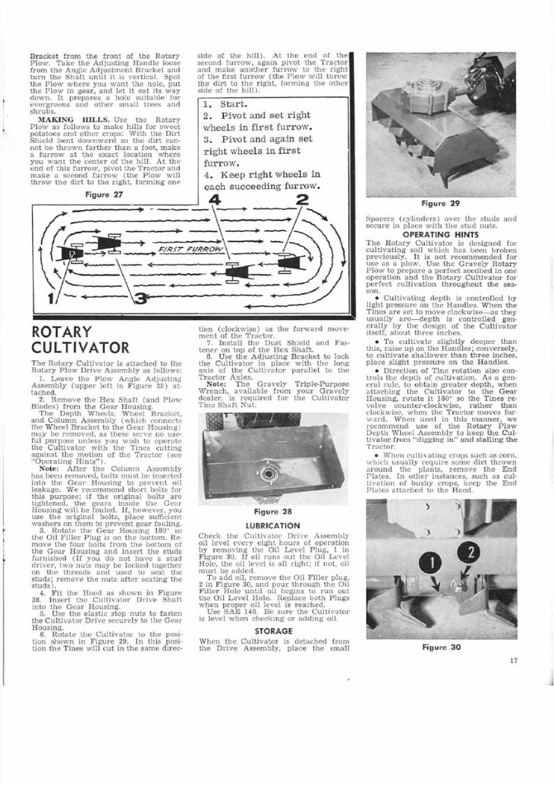
5/13/2018 L8, 1966 Owners Manual - slidepdf.com
http://slidepdf.com/reader/full/l8-1966-owners-manual 19/28
Bracket from the front of the RotaryPlow. Take the Adjusting Handle loose[rom the Angle Adjustment Bracket andturn the Shaft until it is vertical. Spotthe Plow where you want the hole, putthe Plow in gear, and let it eat its waydown. Ii prepares a hole suitable forevergreens and other small trees andshrubs.
MAKING lULLS. Use the Rotary
Plow as follows to make hills for sweetpotatoes and other crops: With the DirtShield bent downward so the dirt can-not be thrown farther than a foot, makea furrow at the exact location whereyou want the center of the hill. At theend of this furrow, pivot the Tractor andmake a second furrow (the Plow willthrow the dirt to the right, forming one
Figure 27
side of the hill). At the end of thesecond furrow, again pivot the Tractorand make another furrow to the rightof the first furrow (the Plow will throwthe dirt to the right, forming the otherside of the hill).
1. Start.
2. Pivot and set right
wheels in first furrow.3. Pivot and again set
right wheels in first
furrow.
4.
ROTARYCULT IVATORThe Rotary Culti va tor is attached to theRotary Plow Drive Assembly as follows:
1. Leave the Plow Angle AdjustingAssembly (upper left in Figure 25) at-
tached.2. Remove the Hex Shaft (and Plow
Blades) from the Gear Housing.The Depth Wheels, Wheel Bracket,
and Column Assembly (which connectsthe Wheel Bracket to the Gear Housing)may be removed, as these serve no use-ful purpose unless you wish to operatethe Cultivator with the Tines cuttingagainst the motion of the Tractor (see"0pera ting Hints").Note: After the Column Assembly
has been removed, bolts must be insertedinto the Gear Housing to prevent oilleakage, We recommend short bolts forthis purpose; if the original bolts aretightened, the gears inside the GearHousing will be fouled. If, however, youuse the origin al bolts, place sufftcren t
washers on them to prevent gear fouling.3. Rotate the Gear Housing 180· so
the Oil Filler Plug is on the bottom. Re-move the four holts from the bottom ofthe Gear Housing and insert the studsfurnished (I[ you do not have a studdriver, two nuts may be locked togetheron the threads and used to seat thestuds, remove the nuts after seating thestuds) .
4. Fit the Hood as shown in Figure28. Insert the Cultivator Drive Shaftinto the Gear Housing.5. Use the elastic stop nuts to fasten
the Culti va l or Dri ve secu rely to the GearHousing.6. Rotate the Cultivator to the posi-
tion shown in Figure 29. In this posi-tion the Tines will cut in the same dlrec-
tion (clockwise) as the forward move-ment of the Tractor.
7. Install the Dust Sh ield and Fas-tener on top of the Hex Shaft.S. Use the Adjusting Bracket to lock
the Cultivator in place with the longaxis of the Cultivator parallel to theTractor Axles.Note: The Gravely Triple-Purpose
Wrench, available from your Gravelydealer, is required for the CultivatorTine Shaft Nut.
:Figure 28
LUBRICATION
Check the Cultivator Drive Assemblyoil level every eight hours of operationby removing the Oil Level Plug, 1 inFigure 30. If oil runs out the Oil LevelHole, the oil level. is all right; if not, oilmust be added. .
To add oil, remove the Oil Filler plug,2 in Figure 30, and pour through tile OilFiller Hole until oil begins 10 run outthe Oil Level Hole. Replace both Plugswhen proper oil level is reached.
Use SAE 140. Be sure the Cultivatoris level when checking or adding oil
STORAGE
When the Cultivator is detached fromthe Drive Assembly, place the small
F.igure 29
Spacers (cylinders) over the studs andsecure in place with the stud nuts ..
OPERATING HINTSThe Rotary Cultivator is designed foculti vating soil which has been brokenpreviously. It is not recommended fouse as a plow. Use the Gravely RotaryPlow to prepare a perfect seedbed in oneoperation and the Rotary Cultivator foperfect cultivation throughout the season.
• Cultivating depth is controlled bylight pressure on the Handles. When theTines are set to move clockwise-c-as theyusually are-depth is controlled generally by the design of the Cultivatoritself, about three inches ..
• To cultivate slightly deeper thanthis, raise up on the Handles; conversely,to cultivate shallower than three inches,place slight pressure on the Handles.
• Direction of Tine rotation also controis ihe depth of cultivation. As a general rule, to obtain greater depth, when
attaching the Cultivator to the GearHousing, rotate it L80· so the Tines revolve counter-clockwise, rather thanclockwise, when the Tractor moves forward. When used in this manner, werecommend use of the Rotary PlowDepth Wheel Assembly to keep the Cultivator from "digging in" and stalling theTractor.
• When cultivating crops such as corn,which usually require some dirt thrownaround the plants, remove the EndPlates. In other instances, such as cultivation of bushy crops, keep the EndPlates attached to the Hood.
)
)
Figure 30
1

5/13/2018 L8, 1966 Owners Manual - slidepdf.com
http://slidepdf.com/reader/full/l8-1966-owners-manual 20/28
S N O W B L O W E R
MA-210, 211LUBRICATION
All major bearings of the MA-210 andMA-211 Snowblower that require Iubri-cant are permanently lubricated, or arelubricated from the tractor transmission.However, the operator should check theoil level in the gear box by removinzthe upper pipe plug. Oil should comeup to the bottom of this hole. If theoil level should ever be low. add wormtype gear lubricant as recommended for
truck worm-gear axles in your area.See Figure 31.
Figure 31
1. Oil Level and Fill Plug.2. Drain Plug.3. Clutch Adjusting Nut.
ATTACHINGThe Snowblower Drive housing mountsto the front of the tractor with four bolts,the same as other Gravely power At-achments. When attaching to the Model
'V Tractor, the chute control crank
18
should be attached to the top sprockethousing shaft of the Snowblower withthe rubber conn CtOT and two (2) clampswhich are provided. See Figure 32.
The crank should then be mounted tothe tractor left-driving handle with thecrank support and crank support clampas shown in Figut'e 33.
Figure 33
ote: If the Snowblower is unevwith the ground alter mountingractor, adjust the air pressure intractor tires.
ADJUSTMENTS
Dr CHARGE CHUTE. To positionDischarge Chute, turn the control craThe Discharge Chute will rotate appr
ima ely 165 degrees from extreme l
through the vertical position, to thetreme right. As the crank is turned,deflector opening is also rotated frthe extreme left position through award position approximately 180 degrto the extreme right position.
DEFLE TOR, To provide accuraplacement of the blown snow nearblower on either side or forward throloosen the large wing nut on theflector and adjust t.he deflector positio
KID . To raise or lower the Snoblower cutting edge, first disengagepower take-oft and stop the tractorgine. Then loosen the skid mountibolts and slide the skids up or downdesired, and tighten the skid mountibolts securely. This adjustment canmade more accurately if the cuttiedge is placed on blocks while thejustment is made.
REEL CLUTCH. The Reel Clutchproperly adjusted at the fac ory. Ishould become necessary 1:0 tightenprotective Iriction clutch in the reeturn off the tractor engine, disengathe power take-off, and block the rotion of the fan. Now tighten the lanut on the left end of the reel sh(as viewed from the rear of the Snoolower ). See Figure 31.The nut should be tightened to 85
95 lb. feet of torque. This would belbs, force at the end of a 12 inch wrencor 72 lbs. at the end of a 15 inch wrencor 60 lbs. at the end of an 18 inwrench, OVer tightening can cause da
age to he Snowblower.CONTROL HAFT CL TOH. The
housing is prevented from rotating bsmall friction clutch on the top sprockhousing shaft, except when the contcrank is turned by the operator. Tresistance of the clutch may be variby adjusting the nut on the top sprockhousing shaft. Adjust the nut so thatis just tight enough to prevent thehousing [rom rotating during operatioof the Snowblower except when thehousing is rotated by the control cran
ACCE~SORIES
A special Accessory Kit is availabwhich includes:DRIFT TTERS. Two Drll,t Cutte
are provided. These mount insidereel housing ends and extend upwato slice through snow up to 30 inchdeep. The Drift Cut ers are flaredassist in turning in deep snows. Nojustment is necessary.
CA TER . Two caster weldments amounting brackets are included. Thebolt to the inner sides of the frame amay be used in place of the skids.
The caster bracket holes are slotteand wee (3) pairs of holes are providein the frame for height adjustment.
OPERATING HINTS
Keep the engine under full load whusing the Snowblower. With the Swiftmatic Transmission, use low axle rang

5/13/2018 L8, 1966 Owners Manual - slidepdf.com
http://slidepdf.com/reader/full/l8-1966-owners-manual 21/28
Figure 33·A
Figure 33·B
If you ha ve standard transmission, youwill have to shift between high and lowin keeping with snow depth and density.For extended operation in hea vy snows,we recommend use of the Gravely gear-reduction wheels,
II the tractor stops suddenly whileoperating the now blower, check thevent in the fuel Lank cap, We recom-
mend use of anti-ice fuel additives, andkeeping the fuel tank as full as possible,
SA FE SNOW REM OVAL
IS NO A CCIDENT
Improper use of snow removal equip'rnent on the part of the operator canresult in injury. To reduce this possi-bility, give complete and undivided attention to the job at hand.Protect yourself and others by follow-
ing these safety tips:1. Stop motor before removing ob
stacles, making adjustments (exceptwith he control crank), or when leavingth operating posi ion.2. Disengage the power take-off and
wait. till the fan stops before adjustingthe Deflector. Nev r direct discharge abystanders, or allow anyone in front omachine-debris may be hidden in thesnow.3. Keep children and pets a safe dis
tance away.'i. Do not allow children to operate
machine, nor allow adults to operate iwi thou t propel' instruction.5. Adjust height to clear gravel o
crushed rock surface.6. Exercise caution to avoid slipping
or falling, especially when operating inreverse.
7. Know the controls and how to stopquickly.
P O W E R B R U S HThe Power Brush is a useful tool forcleaning parking lots, drives, sidewalks,and other areas where power sweepingis necessary. The Brush can be used forsweeping ligh t snows-up to six inch esin depth-clean to the pavement unlessth re is an ice skim on the pavement.
LUBRICATION
Check the Drive Assembly oil levelevery eight hours of operation by re-moving the Oil Filler Plug, 1 in Figure34, and observing whether the gears dip
halfway in the oil.
Add oil, if necessary, through the OilFiller Hole. Use SAE 14.0.
Be sure the Tractor and Brush arelevel when checking or adding oil.
Use General Purpose Grease in thegrease fitting (or grease cup) on the
Drive Assembly (this is close to thepoint where the Drive Assembly is at-tached to the Tractor).
ADJUSTMENTS
To adjust the Chains, simply remove ahalf link when the Chain has been driv-ing long enough io "stretch." This us-ually occurs after several months of use.
To adjust Brush contact, put the Brushin contact wi h he ground by lifting up011 the Brush Can ac Lev r, 2 in Figure
34. Then tum the Brush Tension Adjust-ing Bolts, 3 in Figure 34, until propertension is reached.
Proper Brush tension must be learnedby experience. The Brush, of course,must be placed under sufficient pressureto enable it to sweep clean. Always ad-just Brush tension downward until cor-rect tension is obtained. ote: Toomuch pressure win cause the BrushStrips to wear out prematurely.
Power Brush
REVERSING OR CH ANG ING
BR USH STR IPS
When it appears the Brush Strips haveworn more on one side than on theother, it is time to reverse the Stripsin the Brush Spiders. To do this, loosenthe bolts which hold the Strips in theSpiders and remove the Strips. Thenreverse the Strips (or replace, when necessary, with new Strips obtained fromyour Gravely dealer) and tighten thebolts. Adjust to proper tension followingprocedures outlined above.
TRANSPORTING
TH E BRU SHTo save unnecessary wear on the Brushstrips when going to or from a job, pushdown on the Brush Contact Lever toraise the Brush off the ground.Brush life will be increased greatly by
wetting the Brush Strips before use, andkeeping them wet during prolonged use
Figure 34
1

5/13/2018 L8, 1966 Owners Manual - slidepdf.com
http://slidepdf.com/reader/full/l8-1966-owners-manual 22/28
GravelyNon-Power
Att achmentsCULTIVATORTOOL HOLDERThe Cultivator Tool Holder, shown inFigure 35, can be used to hold a varietyof cultivating tools. The most commonset-ups of cultivating tools in the ToolHolder are shown on the opposite page.
In addition, the Cu Ii v a t or Too IHolderis used to hold the 36-inch ScraperBlade.
ATTACHING TO TRACTOR. TheTool Holder is attached to' the [rant of
the Tractor by four bolts, as are powerattachments. The Attachment ClutchLever (or Attachment Clutch Control)should be at the OUT position.ATTACHING TO. 0. L S TO. TOOL
HQL.DER. The individual cultivatingtool, ! in Figure 35, is attached to aShank, 2 in Figure 35, which in turnis attached to the Tool Holder by aShank Holder, 3 in Figure 35.The Tool Holder comes from the fac-
tory with five Shank Holders. Thesemay be moved to different positions onthe Tool Holder, if desired, although thisis seldom necessary. Additional ShankHolders may be purchased from yourGravely dealer.Cultivating tools are divided into two
classes - those requiring the one-hole
Shank and those requiring the two-holeShank. W~th the exception of the Fur-rowers, Hillers, Shovel Steel, and 'I'urn-
ing Shovel, cultivating tools require theone-hole Shank.To attach a tool to its Shank, simply
bolt it in place with the nuts and boLtsprovided.To attach the Shank to the Tool
Holder, loosen the hexagon-head capscrew in the side of the Shank Holder,slip the Shank into the Shank Holderfrom the bottom, and leek the Shank inplace at the desired position by tighten-ing the cap screw.
CHANGING TOOL. After theShanks have been attached to the ToolHolder, changing cultivating tools reoquires only the unboleing o:f the old tool
hom its Shank and bolting the new toolon. However, if the new tool requires atwo-hole Shank in place of a one-holeShank, the Shank also must be changed.PARALLEL BARS. The Parallel Bars,
.. in Figure 35, can be adjusted in sev-eral ways, depending on the task Usu-ally it is necessary to detach the Barsfrom the Depth Wheels to make thesedifferent set-ups.
ADJ TMENTS. The Depth Wheelsare used to set the depth the culti vatingtools penetrate the ground Facing theDepth ViI"heels, turn the Handwheelsclockwise for deeper cultivation andcounter-clockwise for shallower cultiva-tion.Usually the Depth Wheelsprovide all
the adjustments required. However, if
20
.Figure 35
required, the Shanks can be moved upor down in the Shank Holders for ad-ditional adjustment.
LUBRICATION
No lubrication is required.
OPERATING HINTS
Individual problems and preferencesusually wiI! govern the cultivating depthand how close to the plants you culti-vate. However, these suggestions gener-ally will be helpful:
" Cultivating depth within the pathof the Tool Holder may be adjusted by
the individual Shanks. For example,Shanks may be set for deep cultivationin the center, while barely stirring thedirt next to the plants. This cuts downall. hand-hoeing, and does not damagethe plants when done with care.
I Rows should be planted enoughapart to accommodate the Tradal' andTool Holder. Normal distance betweenrows is 32 to 36 inches. Rows shouldbe planted farther apart for plantswhich spread widely, unless you intendto shield the Tool Holder so plants willnot be damaged.
" The Tool Helder and cultivatingtools are very useful Ior stirring up deeplitter in brooder houses.
• When cultivating very hard or stony
ground, place a 50·pound sandbag on theTool Holder La keep it from bouncing.Use of the sandbag makes no appre-ciable difference in \112 handling of theTractor.
Note: Users sometimes ask us whythe Tool Holder is not made heavyenough so use of the 50-pound sandbagis not necessary. To make the ToolHolder 50 pounds hea vier would requirea price increase of S 18 to $22. We be-lieve users' interests are served betterby recommending this simple and inex-pensi ve way to obtain lhe needed weigh t,when necessary, rather than forcingusers to pay more money unnecessarilyfor the attachment.See Page 22 for Rear Culti vator Tool
Holder.
SCRAPER BLADEThe Scraper Blade, not illustrated,useful for small grading jobs, suchsmoothing seedbeds and removingsnowfalls from walks and driveways.It is attached to the Cultivator
Holder by one-hole Shanks.No lubrication is required.
4 8-IN 'CH SNOWPLOWThe 48-inch Snowplow clears the aage walkway in one pass, the averdriveway in two .. Itmoves snow as
as 18 inches. Key to its efficiency iunique design-instead of pushingsnow, the Snowplow rolls it out .ofway.The Snowplow has many uses in
dition to removing snow .. These arecussed under "Additlonal Uses."
Snowplow

5/13/2018 L8, 1966 Owners Manual - slidepdf.com
http://slidepdf.com/reader/full/l8-1966-owners-manual 23/28
DIU TMENT . The current Snow-pi w has a Swivel Casting (the SwivelCasting is the part which is attached tothe front of the Tractor) which has threeholes in it. The Snowplow can be ad-justed so there is swivel action, allowingthe Blade to follow closer the groundcontour, or it can be set so the Blade isheld rigidly.The older Snowplow does not have
this swivel action feature; its Swivel
Casting has only one hole.Both models can be adjusted to roll
the snow straight ahead or to the len orright.To set the n 'W Snowplow to roll
straight ahead with swivel action, lineup the cent r hole in the Swivel Bracketwith the center hole in the Swivel Cast-ing and insert the T·shaped AdjustingPin. To hold the Blade rigidly in thestraight-ahead position, insert the Pinin the holes on either side of the centerholes.To roll snow to the left wi th swivel
action, line up the left (left, as youstand at the Handles) hole in the SwivelBracket with the center hole in heSwivel Casting and insert he Pin. Tohold the Blade rigidly in the left position,
insert the Pin in the holes immediatelyto the righ t,To roll snow to the right with swivel
action, line up the right (right, as youstand at the Handles) hole in the SwivelBracket with lhe center hole in theSwivel Casting and insert the Pin. Tohold the Blade rigidly in the right posi-lion, insert the Pin in the holes imme-diately to the left.
On the older Snowplow, simply movethe Blade to the desired position, lineup the boles in the Swivel Bracket withthe hole in he Swivel Casting, and in-sert the Pin.
WEARING TRIP. The Wearing Stripon the bottom of the Blade eventuallywill have to be replaced. To replace,simply remove the screws, take off theold Strip, put the new Strip on, andlighten the screws firmly.
KID . Skids, available from yourGra vely dealer, are useful when work-ing on concrete dri ves where one side ishigher than the other (thus forming anedge which would catch the Blade) andon gravel or bluestone drives to keep theBlade high enough to remove the snowwithout removing the gravel or stone.To attach U1e Skids, remove the end
screws from tile Wearing Strip and in-sert the long bolts provided with theSkids. Slip the Sltids onto the bolls fromthe rear of the Blade, with the long sidesdown and parallel to the ground. Fastenthe nuts securely on the bolls.
RECOMM.ENDED ACCE ORIE.
Gravely Tire Chains (see Page 6) arehelpful when removing snow from ice-coated pavements. When using theSnowplow for light bu.lldoz ing, the DualWheels described on Page 5 in manycases may be desirable.
L BRI ATIO . No lubrication is re-quired.
ADDITIONAL SES. The Snowplowis used by many landscapers in combina-tion with the Rotary Plow and RotaryCultivator to prepare lawns for seeding.After plowing, the Snowplow can beused to terrace and grade. Many usersgo over the area to be seeded with theTractor in reverse, so that the Snow-plow follows the Tractor. This makes asmooth, even seedbed properly prepared
COM M ON CU LTIV A TING TOOL SET-U PS
FIVE· TEEL ET· P is the standardjsarrangement, l%-inch wide Steels areused. Figure 35 shows a slight mcdifica-tion of this set-up, in which seven Steelsare used. Steels are available in PI4,l%, and 2Jt; inch widths; standard lengthof the Steels is eight inches.
IX·I J H fULLER 'T-UP uses"'>-right and left Hillers; these can be usedfor closing rows as well as for hilling.Hillers can be used to throw dirt awayfrom or around the plants as desired.A turrcwer, available in 10 or 12-inchdepths, can be used with the Hillers tobring dirt from the center of the rowto the Hillers, which in turn throw dirtaround the plants.
for seeding. In some cases, after seed-ing the Snowplow is used in the samemanner, thus setting the seeds at ap-proximately the right depth for goodgermination.
• Dairy farmers use the Snowplow toclean concrete holding pens. Some eventake the Tractor inside barns to scrapeout manure and litter.
• Poultry fanners find the Snowplowuseful for cleaning the inside of brooderhouses of litter and droppings.
• Owners of motels, parking lots, anddrive-in theatres use the Snowplow in reoverse to level gravel and slag driveways.
• Industrial users employ the Snow-plow in unloading bulky materials (suchas sand and gra vel) from barges. Alterthe clamshell has unloaded most of thematerial, the Tractor and Snowplow canbe lowered into the barge to scrape upthe remaining material into piles largeenough for the clamshell to pick up.
Yi~ EVE, s: TEEL V ET- P uses oDepth Wheel with the Parallel Barsranged to form a V. The Tool Holdefollows the ground contour closely, withe two outside Steels shielding foliagand vine crops to prevent damagethe Tratcor Wheels.
WEEP AND HOE ET·UP usesimproved Sweep in U1e center andright and left Gravely Hoe on the side- < : : : The Sweep comes in 8, 10, 12, an18·inch sizes. Tile Sweep clears the cetel' of weeds and trash, while the Hoeliminate the majority of hand woclose to the plants.
F R.RO'''TERS (not illustrated) canused at the front or real' of the Tractoto layoff rows for planting. Also, manusers find the Furrowers good ools fdigging potatoes. For smaller furrowsseven-inch Shovel Steels are availablethese can be used to layoff small seecrops and for center row cultivation.
POWER BARROWThe Gravely Power Barrow, whichtaches to the Iront of the Tractor, ha
dles heavy loads fast and easily.
Dumping the Power Barrow is simpla matter of raising the Handle, arrowFigure 36. The Hopper is balancedhat dumping call be accomplished easilfrom your posi ion at the rear of thTractor.
The only lubrication required isoccasional shot of General PurposeGrease in he grease fittings on tBarrow Wheel and Caster.
Note: Tractors equipped with tElectric Starter must have the Balterymounted on the side when using tPower Barrow.

5/13/2018 L8, 1966 Owners Manual - slidepdf.com
http://slidepdf.com/reader/full/l8-1966-owners-manual 24/28
Figure 36
UTILITY SCOOPThe Gravely Ut:i.lity Scoop is a durable,efficient tool that performs a wide rangeof materials handling jobs for home,
farm, and industry. Among its majoruses are light landscaping and grading,transporting sand, gravel, and similarmaterials, and removing snow fromwalks, driveways, and parking areas.
Figure 37 Figure 38
Figure 39
LUBRICATION
The only Iubrication required is an oc-casional light application of GeneralPurpose Grease on the Locking Pins(which protrude through the Frame tohold the Scoop in the loading position).
ATTACHING
The Scoop is attached to the front ofthe Tractor by four bolts. When at-taching, it must be inverted fully to theposicion shown in Figure 38.To attach the dumping "Control mecha-
nism, return the Scoop to the loading
position. Extend the Control Linkage,
22
1 in Figure 39, fully, and attach it tothe Locking Pin Rod, 2 in Figure 39,with the key and pin provided. Thenattach the Actuating Lever, as shown inFigure 37, to the Tractor Handle, usingthe clamp, bolts, and nuts provided.
OPERATING INSTRUCTIONS
To load, ease the Scoop into the materialuntil filled sufficiently. Back the Tractoroft', bearing down on the Handles toraise the Scoop.To transport, simply guide the Trac-
tor, keeping slight pressure on the Han-dles to keep the Scoop elevated.To dump, depress the Tractor Handles
enough so the Scoop can be moved di-rectly over the place where dumping isdesired. Keeping the Scoop elevated,push the Actuating Lever forward tounlock the Scoop from the .Frame. Theweight of the load will cause the Scoopto pivot downward, emptying all con-tents.Back the Tractor off, simultaneously
decreasing pressure on the Handles. Thisdrops the Scoop to the ground, lockingit in the loading position.
Note: With the Scoop fully invertedas shown in Figure 38, the Scoop maybe used as a blade to level dumpedmaterials.
REAR CULT IVATORTOOL HOLDERTo secure the Rear Cultivator ToolHolder to the Rear Hitch Frame, firstline up the notches, arrows in Figure40, with the Rear Hitch Frame cross-member to which the Ball Stud is at-tached. Bolt the Tool Holder to theFrame with the nuts and bolts provided.
All cultivating implements designed
[or the Cultivator Tool Holder fit theReal' Cultiva or Tool Holder, and. areattached in the same manner. Cultivat-ing depth adjustment is the same as forthe Cultivator Tool Holder.No lubrication is required.
Figure 40
STEERI NG RI DERThe Gravely Steering Rider (which isshown in the 50-inch Rotary Mowerphoto on Page 10) lets you s eel' theTractor effortlessly and comfortably.You steer as you would your automo-bile-it's that easy.An optional Rider Seat Cushion, made
of soft foam rubber and plastic, may
be purchased from your Gravely dealer.
ote: Dual Wheels should alwbe used on he Tractor with the SteeRider.
ATTA HlNG. The Steering Ridebolted to the Rear Hitch Frame ..
E T ADJU TIVmNT. The Seatbe moved forward or rearward to myour requirements. When delivered,Seat Spring is bolted to the Frathrough the middle two of four hole
the Frame.To move the Seat forward, loosen
nuts and linthe Seat Spring fromFrame. Move both bolts forwardhole, making sure the small pulleythe rearward bolt still forces the Sting Cables to cross over. ReplaceSeat Spring on the bolts, put the washon, and tighten the nuts securely.
To move the Seat rearward, loboth nuts and lift the Seat Springthe Frame. Leaving the bolt which hthe small pulley in place, move the obolt to the rear most hole in the FraReplace the Seat Spring, put the washon the bolts, and lighten the bolts firm
TEERING CARL' ADJU 'l'l\:lEProper adjustment of the Steering Ca
is vital 1'01' satisfactory operation. Wthe Wheels in line with the Frabe sure tension on both Cables issame. Tension is adjusted by theon the end of the threaded portioneach Cable. Check this tension atsonable in ervals,
LUBRI ATIO . The only lubricatirequired is an occasional shot of Geral Purpose Grease in the grease fion each wheel.
RIDERThe Gravely Rider (see Sickle Mophoto on page 9) lets you guide
Tractor easily while you ride comfably.An optional Seat Cushion, made
soft foam rubber and plastic, maypurchased from your Gravely represta tive.ATTACHThTG. The Rear Hitch
Split,Socket Connection are required
EAT ADJ Tl\I[E T. The Sealbe moved forward or rearward toyour requirements. Simply detachSeat Spring from the Frame, movto the desir d posi·tion, and re-attachto the Frame by the provided
and bolts.
L RRI ATIO . The only lubricatirequired is an occasional shot oferal Purpose Grease in the grease fitt
on the Wheels.
DISC HARROWThe Disc Harrow, not illustrated, ismainly for cultivation, as the RoPlow prepares a perfect seedbed wdoes not require harrowing or dragg
'l'TA BING. The Rear HitchSplit-Socke Connection are required.
PITCH ADJU TMENT. Pitch ofDiscs is adjusted by a clamp screw wactuates a rod that controls the aof pitch.
L BRICATION. An occasional shoGeneral Purpose Grease on the Axl
the only lubrication required.

5/13/2018 L8, 1966 Owners Manual - slidepdf.com
http://slidepdf.com/reader/full/l8-1966-owners-manual 25/28
TURN PLOWThe Turn Plow, shown below, is a use"
Iul tool for breaking soil. The RearHitch and Split-Socket Connection are
required.
HAY RAKEThe 48-inch Hay Rake makes quick workof clearing land of cut weeds and heavygrass. It is a usefulattachment for workin conjunction with the Sickle Mower.
A Lever in easy reach of the operatorquickly raises or lowers the Rake.
The Rear Hitch and Roller-Rest Con-nection are required,
Use the method under "SecuringLoaded Attachments," always to attachthe Hay Rake ..
No lubrication is required other thanan occasional application of GeneralPurpose Grease to the Wheels,
Hay R a k e B-+
REAR H ITCH IN STRU CT IO NSNon-power attachments used on the rearof the Tractor are classified according
to the manner each is secured to theRear Hitch:• Attachments bolted to the Rear
Hitch Frame: Rear Cultivator ToolHolder and Steering Rider;
• Attachments using the Split-SocketConnection: Disc Harrow, Turn Plow,
and Rider; and, . .• Attachments using the Roller-Rest
Connection: Hay Rake, Lawn Roller,Transportation Cart, and 5-foot Seeder·
Spreader.When using an attachment on the rear,
if you are not using an attachment onthe front of the Tractor at the same time,the front of the Tractor must be pro-tected by an Attachment Boss Cover andgasket, or the Cultivator Tool Holder(without cultivating tools).The
AttachmentBoss Cover and gas-
ket are secured to the front of the Trac-tor by four bolts, in the same manner aspower attachments are secured.
ATTACH ING REAR HITCH
The Gravely Rear Hitch, shown in Fig-ure 41, is attached as [allows:
1. A llach the Bra ces, 1 in Figure 41,to the Rear Hitch Frame loosely, usingthe bolts, nuts, and lockwashers pro-vided. Be sure the short twist on each
Brace is down.2 _ Remove the second bolt from the
bottom on both Tractor Axle Housings.
Figure 41
Slip the Frame into place, with thecross-member at the extreme end of theFrame on top. Use the two long boltsprovided to secure firmly the Frame tothe Tractor Axle Housings.
3.. Remove the nuts from the FanHousing, slip the Braces all, and replacethe nuts. Note: On Tractors with SerialNumbers less than 80,000, the length ofthe stud on the Brackets which hold theFan Housing to the Tractor may be in-adequate if both the Rear Hitch Bracesand Governor Bracket are mounted. Inthis case, see your Gravely dealer forBrackets of the proper length.
4. Place the large nut on the BallStud,2 in Figure 41, and run it up to theend of the threads. Screw the Ball Studinto the hole in the cross-member on theend of the Frame. Place the second nuton the Ball Stud and lock both nutstightly against the cross-member. Be
sure the Ball Stud hangs under the cross-member and not on top of it.
5. Tighten securely -the nuts whichhold the Braces to the Rear HitchFrame.
ore: The bottom of the Ball Studhas an opening into which will fit al/.!-inch Allen wrench.
LE VE LIN G THE TR AC TO R
Sometimes it is necessary to "level" theTractor when using the Rear Hitch tokeep the Handles from hitting yourknees when turning. To do this, loosenthe lock nuts on the Ball Stud and turnthe B'a11 Stud (with a %-inch Alienwrench) clockwise to raise the Handles(or counter- clockwise to lower the Han-dles).Note: After this adjustment, be sure
lhe lock nuts on the Ball Stud are tighJt-ened securely.If there still is interference, loosen
the rearmost bolts which hold the Han-dies to the Tractor, move the Handlesup (or down) wi thin the slots un til theproper height is reached, and tightenthe bolts securely.
S PL IT-S O CK ET C O N N E C TIO N
The Disc Harrow, Turn Plow, and Rid-ing Sulky require the Split-Socket Con-nection. To secure the Harrow or Riderto the Rear Hitch, first place the Split-Socket around the Ball Stud. Next, in-sert the end of the Split-Socket into thehollow Draw Baron the attachment,lining up the hole in the Draw Bar \viththe hole in the end of ,the SpUt-Socke1:.Insert the Pin through both holes.Be sure the nuts on the Ball Stud are
locked securely against the cross-rnem-
_ Jbel'. These nuts, rather than the threadeportion of the Ball Stud, absorb tthrust. Unless both nuts are tightenesecurely, the threads in the hole in tcross-member may be stripped.
ROL LER ·REST CONNECT ION
The Roller-Rest Connection is used tocure these attachments to the Rear Hitc
Hay Rake, La IVn Roller, TransportationCart, and 5-foot Seeder-Spreader.Assemble the Roller-Rest Connectio
by slipping the RoUer over the smalleslightly-tapered end, and securing itplace with the Retaining Ring.SECURiNG UNLOADED ATTAC
MENT . To secure an unloaded attacment, place the Roller-Rest Connectioso the Ball Stud fits into the openingthe Connection and the Roller reststhe lower cross-member of the HitFrame. While holding the Connectionthis position, bring the hollow Draw Bover the end of the Connection, linethe holes in the Connection with thosethe Draw Bar, and drop the pin in plac
SECURING LOADED ATTACHMENT. To secure a loaded attachmentsecure the Connection to the Draw BBring the Tractor to the attachment, a
tilt the Tractor forward enough to guithe roller end of the Connection inposition on the lower Fra.mecross-mem-bel'. Then lower the Tractor to its nmal position so that the Ball Studinto the opening in the Connection.Level theT'ractor, if required.

5/13/2018 L8, 1966 Owners Manual - slidepdf.com
http://slidepdf.com/reader/full/l8-1966-owners-manual 26/28
LAWN ROLLERThe Lawn Roller makes easy the jobof smoothing out rough places on lawns.It is 32 inches wide, has round edges toprevent lawn damage, and weighs 655pounds when filled to capacity withwater-plenty of weight to press downrough spots, but not too heavy to keepthe powerful Gravely Tractor from mov-
ing it to practically anywhere you needi t .
ATTA BING TO TRA TOR. TheRear Hitch and Roller-Rest Connectionare required.FILLING TIlE ROLLER. Move the
Roller until the Filler Plug (a largebrass plug on the right side of the Rol-ler) is at its highest point. Simply reomove the Plug to fill the Roller; be sureit is replaced after filling. Water gen-erally is used.LUBRICATION. An occasional greas-
ing of the Axles with General PUrposeGrease is he only lubrication required.To lubricate, remove the cotter pin andslip off <the large washer. Make sureboth are replaced.
TRANSPORT A llONCARTThere's always hauling to be done-andwith the Gravely Transportation Cart
you have a rugged, dependable vehiclewhich can handle a I,OOO'pound load.Cart sides are removable, and stakes
can be substituted for hauling bulkyloads, such as hay. Pneumatic Tires arestandard equipment.ATTACHING TO TRA TOR. The
Rear Hitch and Roller-Rem Connectionare required.
DUMPING. The Cart is dumped byreleasing the Latch which holds the Cartto the Frame and til ting the Cart to
the rear.
LUBIUCATION, The only lubricationrequired is an occasional shot of GeneralPurpose Grease in the grease fittings onthe Wheels.
5-FOOT
SEEDER-SPREADERThe 5-foot Seeder-Spreader is a veryuseful a tachment for seeding large lawnareas, as well as for spreading fertilizer.Its 300-pound capacity and extra widthmake it an ideal means ot seeding orfertilizing large areas.
ATTACHING TO TRACTOR. TheRear Hitch and Roller-Rest Connectionare required.
DISTRIB TION ONTROL. To de-erm ine the propel' distribution of seedor fertilizer, refer to the self-explanatoryplate attached to the Hopper. Simply set
Transportation Cart
24
the Port Lever to the indicated opento distribute seed or fertilizer proper
CARE OF HOPPER AS EMBMany materials used in the SeedSpreader, especially certain fertilizeare corrosive. Abrasives also are pent. This means the protective psoon will weal' off the Port Assemand Agitator. To protect these surfacwash the Seeder-Spreader thoroughwith water after using and let itpreferably in the sun, If you do nottend to use it again wi hin a few dpour a small quantity of oil alongPort Openings and work the Port Leback and forth to distribute the oil.
LUBRI ATION. Use General PUrpGrease occasionally in the grease fiton each Wheel.
5-foot Seeder-Spreader
lawn Roller

5/13/2018 L8, 1966 Owners Manual - slidepdf.com
http://slidepdf.com/reader/full/l8-1966-owners-manual 27/28
OWNER1S EQ UIPMENT RECORD
LAW N SW EEPE R
A D D I T I O N A L
A T T A C H M E N T S
F O R Y O U R
G R A V E L Y
Tractor Serial Number
LA WN AE RA TO R
To provide even greater versatility
for you, Gravely has arranged with
other reliable manufacturers to fur-
n ish add itiona I attach ments for the
Gravely Tractor.
These attachments, some of
which are shown here. are care-
fully adapted to Gravely specifica-
tions, and are fully warranted by
their manufacturers.
Your Gravely dealer can obtain
these special-order items for you
quickly,
To keep fully abreast of the full
line of Gravely equipment, may
we send you a copy of our latest
four-color catalog? It's free, so
write now .
. U T IL ITY PUMP
C OM PO ST S HR ED DE R
GENERATOR
S IN G LE -R OW S E ED ER
Description Model Number
___Tractor Manufacturing Number
Identifying Marks Other Than Above
Carburetor Model NumberPurchased From _
Gravely Representative's Telephone Number
Magneto Model Number
EQ UIPMENT LIST
Model Numb.. I Description
5/13/2018 L8, 1966 Owners Manual - slidepdf.com
http://slidepdf.com/reader/full/l8-1966-owners-manual 28/28
Lubrication Check L ist
TRACTOR
RECOMMENDED OILS. Summer: SAE 30 or SAE IOW-30. Win-ter (320 or below) : SAE 20W or SAE IOW-30.
OIL LEVEL. Check oil level do ily before sta rting Eng ine. OnTractors with Dipstick, fill to FULL mark. On Treeters withoutDipstick, fill until oil runs out Oil Level Hole.
01L CHANGES. Change oil every 20 hours during 40 - hourbreak-in period. After break-in, change oil every 60 hour\ undernormal conditions, or every 40 hours under very dusty or di.rtyconditions. Change oil every 40 hours during extended com.mer-cial use.
OIL FILTER. Satisfactory performance is assured by changing
Oil Filter according to directions every 150 hours (maximum), oronce a season, whichever is shorter period. For best results changeOil ,Filter every 80 hours.
DOUBL,E - GUARD AIR CLEANER. Inspect every eight hoursunder normal conditions, every four under very dusty conditions.Clean as required according to directions. Use same oil as in Tractor.
GOVERNOR. Check oil level daily. Fill to level of Oil CheckValve. In summer use same oil as used in Tractor. In winter (32or below) use SAE 10 or SAE 10W-30.
ATTACHMENTS
GEAR HOUSI'NGS. Check oil level of Gear Housings on mowingattachments every four hours. Check oil level of Gear' Housingson other attachments every eight hours. Fill to required levelwith SAE140 on all attachments except Snowblower; fill Snow-blower Gear Housing to required level with worm type gear lubri-cant as recommended for truck worm gear axles.
GREASE FITTINGS. Use General Purpose Grease occasionallyon, all grease fittings as needed .. Once a season minimum.
BE SURE TO MAI'L YOUR WARRANTY
REGISTRATION CARD!
Parts Lists Available on Request
PIH NTE o 1101JN .T£e STATEs OF A ....ERI CA