Embed Size (px)
Citation preview
L8019-TM_LODI Manual_REVE.indd 1 29/09/2015 16:08:44
THE LOCATOR® OVERDENTURE IMPLANT SYSTEM.FOUR DECADES OF ATTACHMENT KNOWLEDGE INCORPORATEDINTO OVERDENTURE IMPLANTS.
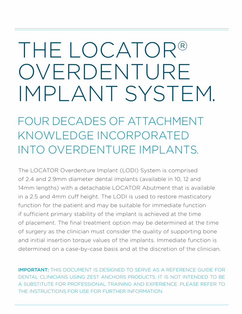
The LOCATOR Overdenture Implant (LODI) System is comprised
of 2.4 and 2.9mm diameter dental implants (available in 10, 12 and
14mm lengths) with a detachable LOCATOR Abutment that is available
in a 2.5 and 4mm cuff height. The LODI is used to restore masticatory
function for the patient and may be suitable for immediate function
if sufficient primary stability of the implant is achieved at the time
of placement. The final treatment option may be determined at the time
of surgery as the clinician must consider the quality of supporting bone
and initial insertion torque values of the implants. Immediate function is
determined on a case-by-case basis and at the discretion of the clinician.
IMPORTANT: THIS DOCUMENT IS DESIGNED TO SERVE AS A REFERENCE GUIDE FOR
DENTAL CLINICIANS USING ZEST ANCHORS PRODUCTS. IT IS NOT INTENDED TO BE
A SUBSTITUTE FOR PROFESSIONAL TRAINING AND EXPERIENCE. PLEASE REFER TO
THE INSTRUCTIONS FOR USE FOR FURTHER INFORMATION.
L8019-TM_LODI Manual_REVE.indd 2 29/09/2015 16:08:44
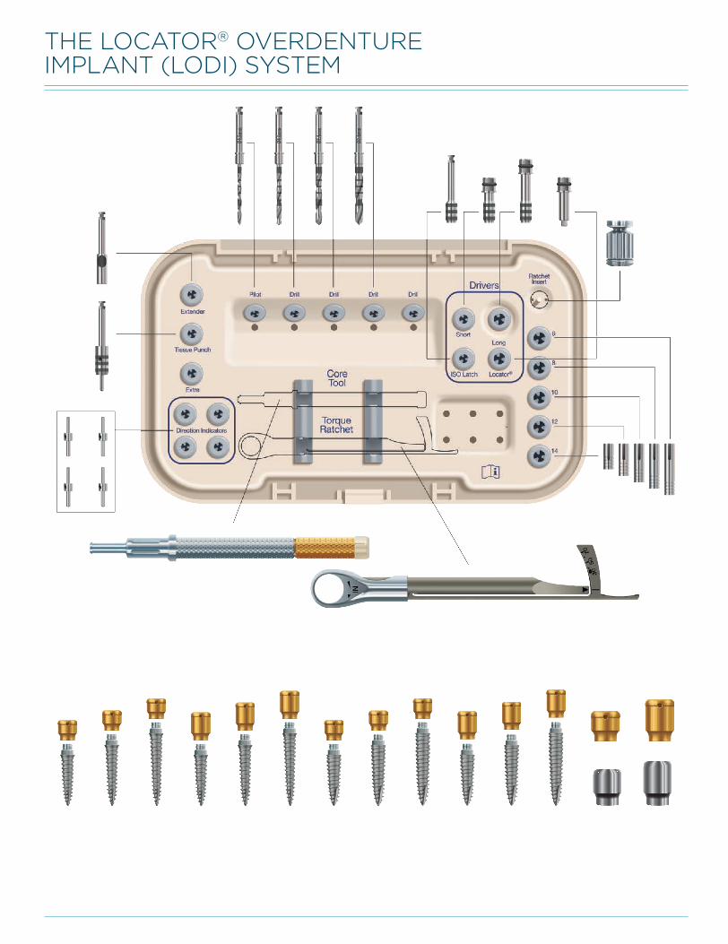
THE LOCATOR® OVERDENTURE IMPLANT (LODI) SYSTEM
L8019-TM_LODI Manual_REVE.indd 3 29/09/2015 16:08:45
L8019-TM_LODI Manual_REVE.indd 1 29/09/2015 16:08:46
1
LOCATOR® OVERDENTURE IMPLANT (LODI) SYSTEM OVERVIEW
6 Drill Laser Depth Markings6 Drill Stops6 Placement of a 2.4mm x 12mm Implant Flapless Surgical Procedure 7 Final Drill Diameter & Depth for Various Bone Types 7 Placement of a 2.9mm x 12mm Implant Flapless Surgical Procedure
15 Direct Technique: Chairside Processing18 Indirect Technique: Laboratory Processing19 Bite Records19 Laboratory Step
20 Denture Try In20 Laboratory Step20 Prosthesis Delivery
25 Inserting and Removing an Overdenture 25 Cleaning an Overdenture25 Additional Notes of Caution
21 Indications21 Contraindications21 Caution21 Storage and Handling21 Delivery21 Single Use Devices21 Sterilization
21 Cleaning Instructions for Instruments & Individually Packaged Replacement Attachments22 Surgical Tray Cleaning Instructions22 Inspection and Maintenance of Cleaned Instruments22 Steam Sterilization Instructions 23 Torque Indicating Ratchet Wrench Cleaning Procedures24 Warnings and Precautions
PRE-OPERATIVE TREATMENT PLANNING
IMPLANT PLACEMENT
LODI HEALING ABUTMENT & LOCATOR ABUTMENT PLACEMENT
IMPORTANT INFORMATION ABOUT THE LODI SYSTEM & SURGICAL INSTRUMENTATION
PROCESSING LOCATOR DENTURE ATTACHMENT HOUSINGS & INSERTS INTO THE DENTURE
OVERDENTURE INSERTION, REMOVAL, & CLEANING GUIDELINES FOR THE CLINICIAN AND PATIENT
ZEST ANCHORS WARRANTY
LODI DIMENSIONS
LOCATOR STANDARD & EXTENDED RANGE INSERTS
LOCATOR 3-IN-1 CORE TOOL
DRILLING DEPTH CONTROL & SEQUENCE EXAMPLES
TABLE OF CONTENTS
3456
10
8
14
EXPLANATION OF SYMBOLS ON OUTER PACKAGING LABELS26
21
15
25
27
L8019-TM_LODI Manual_REVE.indd 2 29/09/2015 16:08:46
2
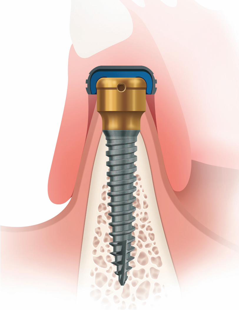
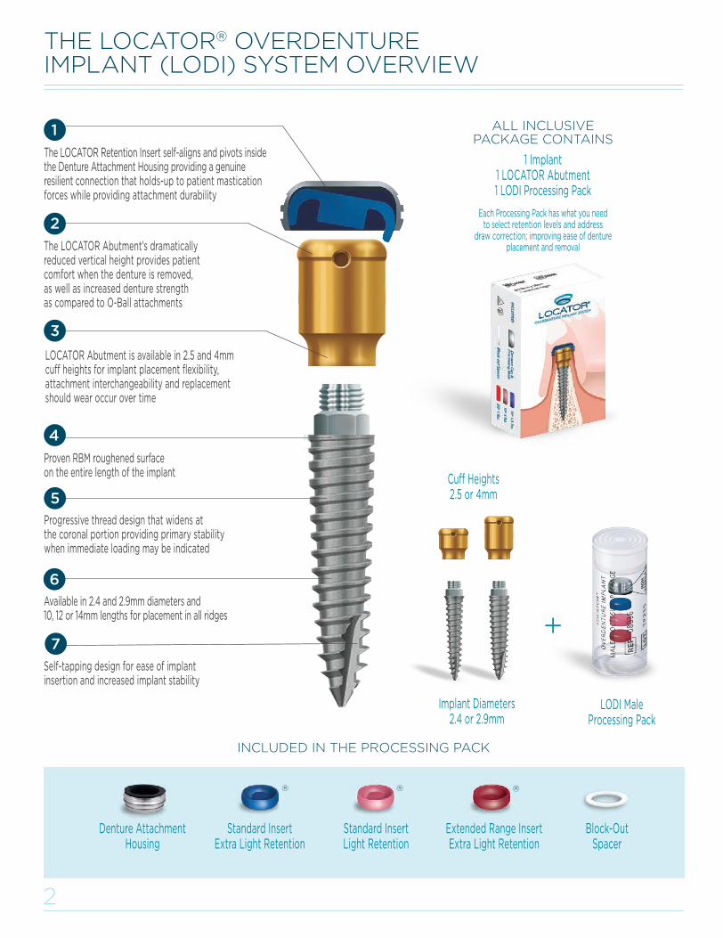
LOCATOR Abutment is available in 2.5 and 4mm cuff heights for implant placement flexibility, attachment interchangeability and replacement should wear occur over time
The LOCATOR Retention Insert self-aligns and pivots inside the Denture Attachment Housing providing a genuine resilient connection that holds-up to patient mastication forces while providing attachment durability
THE LOCATOR® OVERDENTURE IMPLANT (LODI) SYSTEM OVERVIEW
Progressive thread design that widens atthe coronal portion providing primary stability when immediate loading may be indicated
LODI Male Processing Pack
Implant Diameters 2.4 or 2.9mm
Cuff Heights2.5 or 4mm
Denture Attachment Housing
ALL INCLUSIVE PACKAGE CONTAINS
1 Implant1 LOCATOR Abutment1 LODI Processing Pack
Each Processing Pack has what you need to select retention levels and address
draw correction; improving ease of denture placement and removal
INCLUDED IN THE PROCESSING PACK
The LOCATOR Abutment’s dramatically reduced vertical height provides patient comfort when the denture is removed, as well as increased denture strength as compared to O-Ball attachments
Available in 2.4 and 2.9mm diameters and 10, 12 or 14mm lengths for placement in all ridges
Self-tapping design for ease of implant insertion and increased implant stability
Proven RBM roughened surface on the entire length of the implant
Extended Range InsertExtra Light Retention
Standard InsertExtra Light Retention
Block-Out Spacer
Standard InsertLight Retention
L8019-TM_LODI Manual_REVE.indd 3 29/09/2015 16:08:58
3
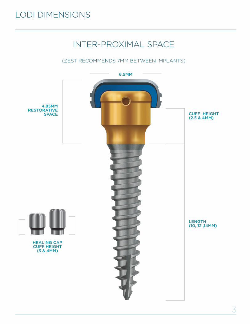
LODI DIMENSIONS
(ZEST RECOMMENDS 7MM BETWEEN IMPLANTS)
6.5MM
4.85MMRESTORATIVE
SPACE CUFF HEIGHT(2.5 & 4MM)
INTER-PROXIMAL SPACE
HEALING CAP CUFF HEIGHT
(3 & 4MM)
LENGTH(10, 12 ,14MM)
INCLUDED IN THE PROCESSING PACK
L8019-TM_LODI Manual_REVE.indd 4 29/09/2015 16:09:00
4
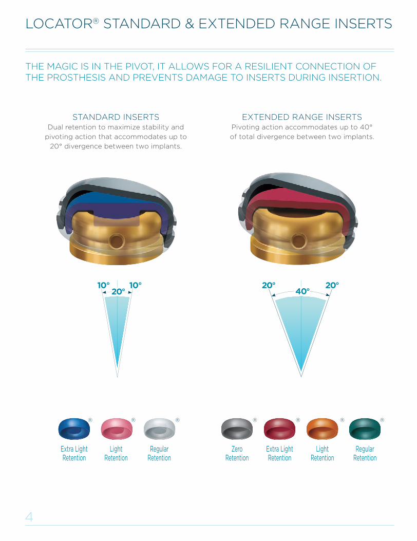
LOCATOR® STANDARD & EXTENDED RANGE INSERTS
STANDARD INSERTSDual retention to maximize stability and
pivoting action that accommodates up to
20° divergence between two implants.
EXTENDED RANGE INSERTSPivoting action accommodates up to 40°
of total divergence between two implants.
Extra Light Retention
LightRetention
Regular Retention
Zero Retention
Extra Light Retention
Light Retention
Regular Retention
THE MAGIC IS IN THE PIVOT, IT ALLOWS FOR A RESILIENT CONNECTION OF THE PROSTHESIS AND PREVENTS DAMAGE TO INSERTS DURING INSERTION.
L8019-TM_LODI Manual_REVE.indd 5 29/09/2015 16:09:00
5
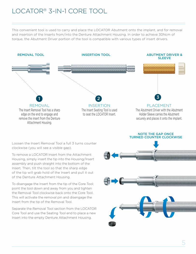
Loosen the Insert Removal Tool a full 3 turns counter
clockwise (you will see a visible gap).
To remove a LOCATOR Insert from the Attachment
Housing, simply insert the tip into the Housing/Insert
assembly and push straight into the bottom of the
Insert. Then, tilt the tool so that the sharp edge
of the tip will grab hold of the Insert and pull it out
of the Denture Attachment Housing.
To disengage the Insert from the tip of the Core Tool;
point the tool down and away from you and tighten
the Removal Tool clockwise back onto the Core Tool.
This will activate the removal pin and disengage the
Insert from the tip of the Removal Tool.
Separate the Removal Tool section from the LOCATOR
Core Tool and use the Seating Tool end to place a new
Insert into the empty Denture Attachment Housing.
LOCATOR® 3-IN-1 CORE TOOL
REMOVALThe Insert Removal Tool has a sharp
edge on the end to engage and remove the insert from the Denture
Attachment Housing.
REMOVAL TOOL INSERTION TOOL ABUTMENT DRIVER & SLEEVE
INSERTIONThe Insert Seating Tool is used to seat the LOCATOR Insert.
PLACEMENTThe Abutment Driver with the Abutment
Holder Sleeve carries the Abutment securely and places it onto the implant.
This convenient tool is used to carry and place the LOCATOR Abutment onto the implant, and for removal
and insertion of the Inserts from/into the Denture Attachment Housing. In order to achieve 30Ncm of
torque, the Abutment Driver portion of the tool is compatible with various types of insert drivers.
NOTE THE GAP ONCE TURNED COUNTER CLOCKWISE
L8019-TM_LODI Manual_REVE.indd 6 29/09/2015 16:09:01
6
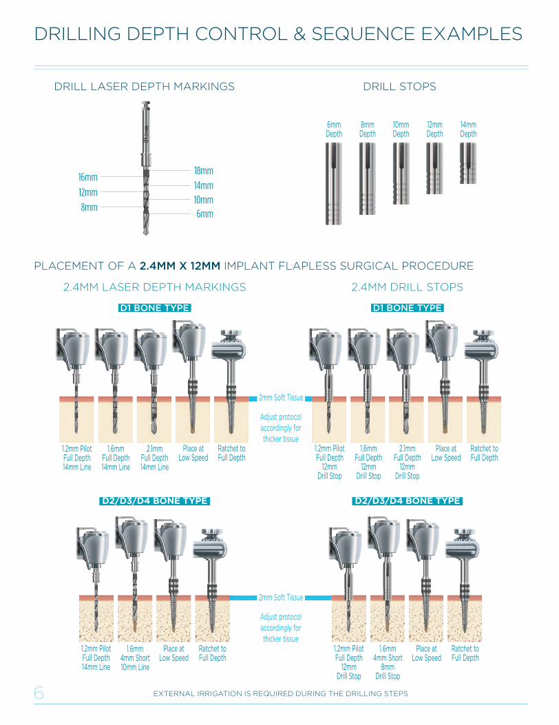
2.4MM LASER DEPTH MARKINGS 2.4MM DRILL STOPS
DRILLING DEPTH CONTROL & SEQUENCE EXAMPLES
EXTERNAL IRRIGATION IS REQUIRED DURING THE DRILLING STEPS
1.2mm Pilot Full Depth 14mm Line
1.2mm Pilot Full Depth
12mm Drill Stop
2.1mmFull Depth
12mmDrill Stop
2.1mmFull Depth 14mm Line
1.6mmFull Depth
12mm Drill Stop
1.6mmFull Depth 14mm Line
Place at Low Speed
Place at Low Speed
Ratchet to Full Depth
Ratchet to Full Depth
1.2mm Pilot Full Depth 14mm Line
Place at Low Speed
1.6mm4mm Short 10mm Line
Ratchet to Full Depth
1.2mm Pilot Full Depth
12mm Drill Stop
Place at Low Speed
1.6mm4mm Short
8mm Drill Stop
Ratchet to Full Depth
2mm Soft Tissue
2mm Soft Tissue
D2/D3/D4 BONE TYPE D2/D3/D4 BONE TYPE
DRILL LASER DEPTH MARKINGS DRILL STOPS
14mmDepth
12mmDepth
10mmDepth
8mmDepth
6mmDepth
PLACEMENT OF A 2.4MM X 12MM IMPLANT FLAPLESS SURGICAL PROCEDURE
Adjust protocolaccordingly forthicker tissue
Adjust protocolaccordingly forthicker tissue
L8019-TM_LODI Manual_REVE.indd 7 29/09/2015 16:09:02

7
DRILLING DEPTH CONTROL & SEQUENCE EXAMPLES(CONTINUED)
EXTERNAL IRRIGATION IS REQUIRED DURING THE DRILLING STEPS
1.2mm Pilot Full Depth 14mm Line
2.4mm Full Depth 14mm Line
1.6mmFull Depth 14mm Line
Place at Low Speed
Ratchet to Full Depth
1.2mm Pilot Full Depth
12mm Drill Stop
2.4mmFull Depth
12mm Drill Stop
1.6mmFull Depth
12mm Drill Stop
Place at Low Speed
Ratchet to Full Depth
1.2mm Pilot Full Depth
12mm Drill Stop
2.1mm4mm Short
8mm Drill Stop
1.6mmFull Depth
12mm Drill Stop
Place at Low Speed
Ratchet to Full Depth
1.2mm Pilot Full Depth 14mm Line
2.1mm 4mm Short 10mm Line
1.6mmFull Depth 14mm Line
Place at Low Speed
Ratchet to Full Depth
2mm Soft Tissue
2mm Soft Tissue
D2/D3/D4 BONE TYPE D2/D3/D4 BONE TYPE
2.9MM LASER DEPTH MARKS 2.9MM DRILL STOPS
Bone type is a general classification. The overall bone quality must be assessed by the clinician through treatment planning and at the time of surgery in order to create the appropriate osteotomy size to achieve the desired insertion torque.
FINAL DRILL DIAMETER & DEPTH FOR VARIOUS BONE TYPES
BONE TYPE2.4MM IMPLANT DIAMETER 2.9MM IMPLANT DIAMETER
FINAL DRILL DIAMETER DRILL DEPTH FINAL DRILL
DIAMETERFINAL DRILL DIAMETER
D1 2.1mm Full Depth 2.4mm Full Depth
D2 / D3 / D4 1.6mmDepth 4mm <
Implant Length2.1mm
Depth 4mm < Implant Length
PLACEMENT OF A 2.9MM X 12MM IMPLANT FLAPLESS SURGICAL PROCEDURE
Adjust protocolaccordingly forthicker tissue
Adjust protocolaccordingly forthicker tissue
L8019-TM_LODI Manual_REVE.indd 8 29/09/2015 16:09:03
8
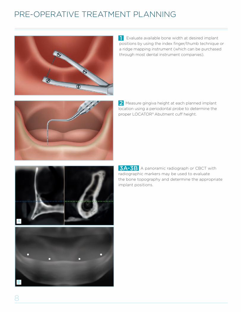
Measure gingiva height at each planned implant
location using a periodontal probe to determine the
proper LOCATOR® Abutment cuff height.
Evaluate available bone width at desired implant
positions by using the index finger/thumb technique or
a ridge mapping instrument (which can be purchased
through most dental instrument companies).
A panoramic radiograph or CBCT with
radiographic markers may be used to evaluate
the bone topography and determine the appropriate
implant positions.
3A-3B
PRE-OPERATIVE TREATMENT PLANNING
B
A
L8019-TM_LODI Manual_REVE.indd 9 29/09/2015 16:09:04
9
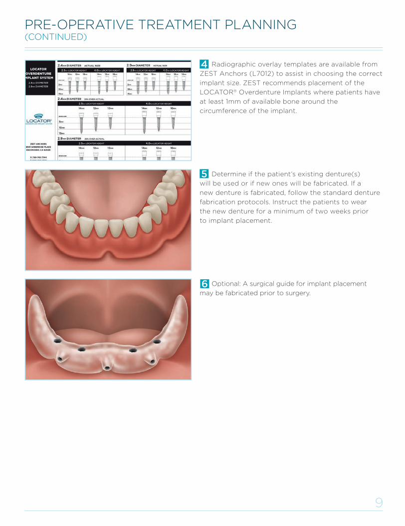
PRE-OPERATIVE TREATMENT PLANNING(CONTINUED)
Radiographic overlay templates are available from
ZEST Anchors (L7012) to assist in choosing the correct
implant size. ZEST recommends placement of the
LOCATOR® Overdenture Implants where patients have
at least 1mm of available bone around the
circumference of the implant.
Determine if the patient’s existing denture(s)
will be used or if new ones will be fabricated. If a
new denture is fabricated, follow the standard denture
fabrication protocols. Instruct the patients to wear
the new denture for a minimum of two weeks prior
to implant placement.
Optional: A surgical guide for implant placement
may be fabricated prior to surgery.
L8019-TM_LODI Manual_REVE.indd 10 29/09/2015 16:09:04
10
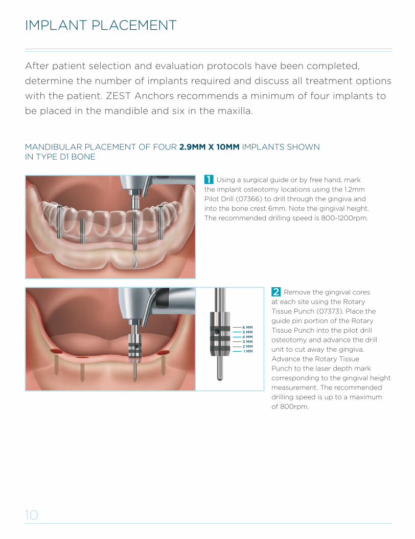
MANDIBULAR PLACEMENT OF FOUR 2.9MM X 10MM IMPLANTS SHOWN IN TYPE D1 BONE
After patient selection and evaluation protocols have been completed,
determine the number of implants required and discuss all treatment options
with the patient. ZEST Anchors recommends a minimum of four implants to
be placed in the mandible and six in the maxilla.
Remove the gingival cores
at each site using the Rotary
Tissue Punch (07373). Place the
guide pin portion of the Rotary
Tissue Punch into the pilot drill
osteotomy and advance the drill
unit to cut away the gingiva.
Advance the Rotary Tissue
Punch to the laser depth mark
corresponding to the gingival height
measurement. The recommended
drilling speed is up to a maximum
of 800rpm.
Using a surgical guide or by free hand, mark
the implant osteotomy locations using the 1.2mm
Pilot Drill (07366) to drill through the gingiva and
into the bone crest 6mm. Note the gingival height.
The recommended drilling speed is 800-1200rpm.
IMPLANT PLACEMENT
FPO 6 MM5 MM4 MM3 MM2 MM1 MM
L8019-TM_LODI Manual_REVE.indd 11 29/09/2015 16:09:05
11
IMPLANT PLACEMENT(CONTINUED)
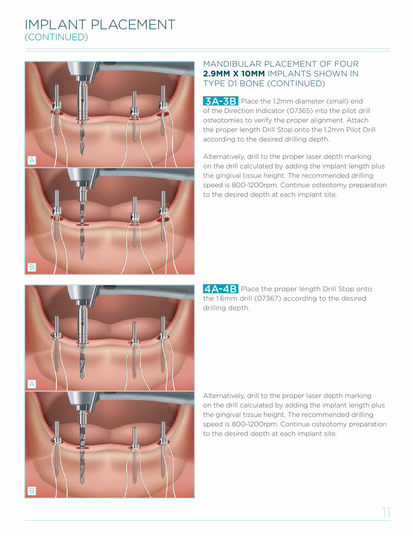
Place the 1.2mm diameter (small) end
of the Direction Indicator (07365) into the pilot drill
osteotomies to verify the proper alignment. Attach
the proper length Drill Stop onto the 1.2mm Pilot Drill
according to the desired drilling depth.
3A-3B
Place the proper length Drill Stop onto
the 1.6mm drill (07367) according to the desired
drilling depth.
4A-4B
MANDIBULAR PLACEMENT OF FOUR 2.9MM X 10MM IMPLANTS SHOWN IN TYPE D1 BONE (CONTINUED)
B
A
B
AAlternatively, drill to the proper laser depth marking
on the drill calculated by adding the implant length plus
the gingival tissue height. The recommended drilling
speed is 800-1200rpm. Continue osteotomy preparation
to the desired depth at each implant site.
Alternatively, drill to the proper laser depth marking
on the drill calculated by adding the implant length plus
the gingival tissue height. The recommended drilling
speed is 800-1200rpm. Continue osteotomy preparation
to the desired depth at each implant site.
MANDIBULAR PLACEMENT OF FOUR 2.9MM X 10MM IMPLANTS SHOWN IN TYPE D1 BONE
L8019-TM_LODI Manual_REVE.indd 12 29/09/2015 16:09:05
12
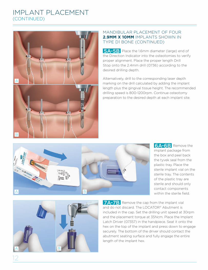
Place the 1.6mm diameter (large) end of
the Direction Indicator into the osteotomies to verify
proper alignment. Place the proper length Drill
Stop onto the 2.4mm drill (0736) according to the
desired drilling depth.
5A-5B
IMPLANT PLACEMENT(CONTINUED)
Remove the cap from the implant vial
and do not discard. The LOCATOR® Abutment is
included in the cap. Set the drilling unit speed at 30rpm
and the placement torque at 35Ncm. Place the Implant
Latch Driver (07357) in the handpiece. Seat it onto the
hex on the top of the implant and press down to engage
securely. The bottom of the driver should contact the
abutment seating surface and fully engage the entire
length of the implant hex.
7A-7B
MANDIBULAR PLACEMENT OF FOUR 2.9MM X 10MM IMPLANTS SHOWN IN TYPE D1 BONE (CONTINUED)
Remove the
implant package from
the box and peel back
the tyvek seal from the
plastic tray. Place the
sterile implant vial on the
sterile tray. The contents
of the plastic tray are
sterile and should only
contact components
within the sterile field.
6A-6B
B
A
BA
Alternatively, drill to the corresponding laser depth
marking on the drill calculated by adding the implant
length plus the gingival tissue height. The recommended
drilling speed is 800-1200rpm. Continue osteotomy
preparation to the desired depth at each implant site.
BA
L8019-TM_LODI Manual_REVE.indd 13 29/09/2015 16:09:06
13
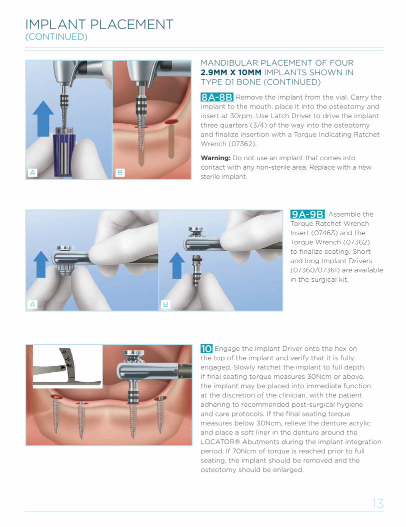
MANDIBULAR PLACEMENT OF FOUR 2.9MM X 10MM IMPLANTS SHOWN IN TYPE D1 BONE (CONTINUED)
Assemble the
Torque Ratchet Wrench
Insert (07463) and the
Torque Wrench (07362)
to finalize seating. Short
and long Implant Drivers
(07360/07361) are available
in the surgical kit.
9A-9B
8A-8B
Engage the Implant Driver onto the hex on
the top of the implant and verify that it is fully
engaged. Slowly ratchet the implant to full depth.
If final seating torque measures 30Ncm or above,
the implant may be placed into immediate function
at the discretion of the clinician, with the patient
adhering to recommended post-surgical hygiene
and care protocols. If the final seating torque
measures below 30Ncm, relieve the denture acrylic
and place a soft liner in the denture around the
LOCATOR® Abutments during the implant integration
period. If 70Ncm of torque is reached prior to full
seating, the implant should be removed and the
osteotomy should be enlarged.
10
Remove the implant from the vial. Carry the
implant to the mouth, place it into the osteotomy and
insert at 30rpm. Use Latch Driver to drive the implant
three quarters (3/4) of the way into the osteotomy
and finalize insertion with a Torque Indicating Ratchet
Wrench (07362).
Warning: Do not use an implant that comes into
contact with any non-sterile area. Replace with a new
sterile implant.
IMPLANT PLACEMENT(CONTINUED)
A
A
B
B
FPO
L8019-TM_LODI Manual_REVE.indd 14 29/09/2015 16:09:07
14
If the implant placement torque was 30Ncm or
greater, follow the steps for processing the LOCATOR
Denture Attachment Housings and Inserts into the
denture. If the implant placement torque was less than
30Ncm, relieve the denture acrylic and place a soft
liner in the denture around the LOCATOR Abutments
during the integration period.
4
LODI HEALING ABUTMENT PLACEMENT
LOCATOR ABUTMENT PLACEMENT
LODI HEALING ABUTMENT & LOCATOR® ABUTMENT PLACEMENT
Thread the LOCATOR Abutment onto
the implant until finger tight. If the implant placement
torque was 30Ncm or greater, the Abutments may
be tightened to the recommended torque level of
30Ncm. If the implant placement torque did not reach
30Ncm, the Abutment should only be hand tightened.
Assemble the LOCATOR Abutment Torque Driver
Insert and the Torque Indicating Ratchet Wrench (07362)
with LOCATOR Torque Wrench Driver (08926) and
torque the attachments to 30Ncm.
Warning: Do not use the LOCATOR Abutment on top of
the implant to further advance the implant into the
osteotomy. If the implant needs to be placed deeper,
remove the Abutment, re-engage the Implant Driver
onto the implant and ratchet to desired depth.
3A-3B
Open the flip cap on the top of the vial
cap and remove the LOCATOR Abutment. Place
the Abutment Holder Sleeve onto the LOCATOR
Abutment Driver and insert into the tri-lobe channel
of the LOCATOR Abutment.
2A-2B
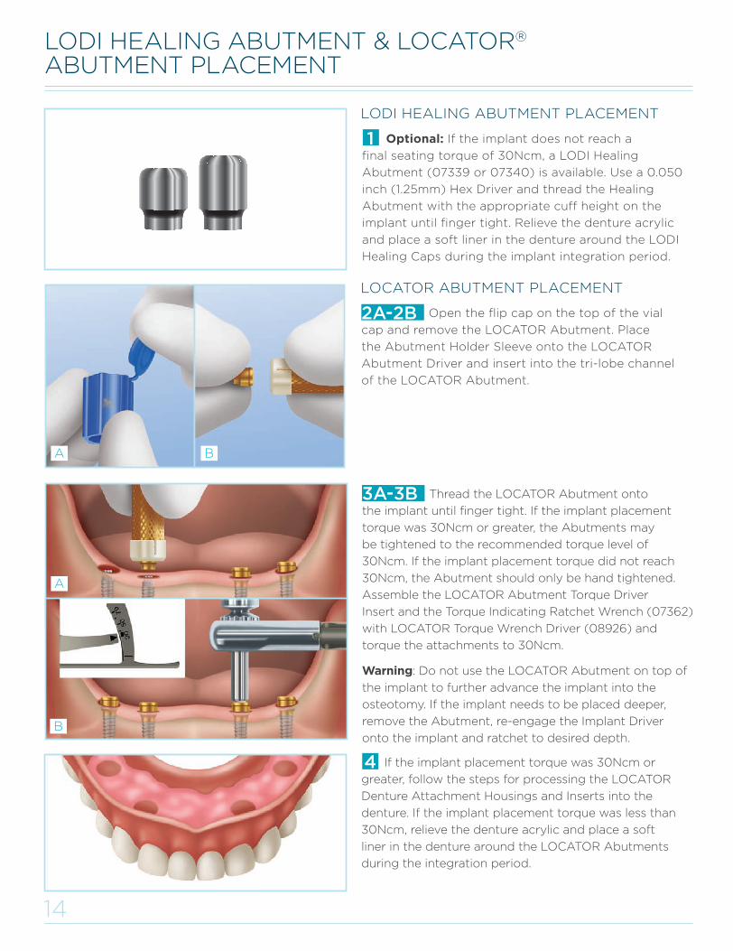
Optional: If the implant does not reach a
final seating torque of 30Ncm, a LODI Healing
Abutment (07339 or 07340) is available. Use a 0.050
inch (1.25mm) Hex Driver and thread the Healing
Abutment with the appropriate cuff height on the
implant until finger tight. Relieve the denture acrylic
and place a soft liner in the denture around the LODI
Healing Caps during the implant integration period.
1
A
A
B
B
L8019-TM_LODI Manual_REVE.indd 15 29/09/2015 16:09:08
15
PROCESSING LOCATOR® DENTURE ATTACHMENT HOUSINGS & INSERTS INTO THE DENTURE
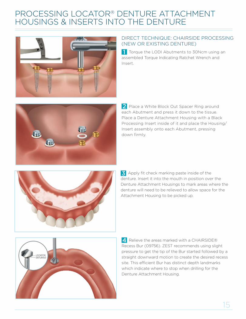
Apply fit check marking paste inside of the
denture. Insert it into the mouth in position over the
Denture Attachment Housings to mark areas where the
denture will need to be relieved to allow space for the
Attachment Housing to be picked up.
Place a White Block Out Spacer Ring around
each Abutment and press it down to the tissue.
Place a Denture Attachment Housing with a Black
Processing Insert inside of it and place the Housing/
Insert assembly onto each Abutment, pressing
down firmly.
Torque the LODI Abutments to 30Ncm using an
assembled Torque Indicating Ratchet Wrench and
Insert.
DIRECT TECHNIQUE: CHAIRSIDE PROCESSING(NEW OR EXISTING DENTURE)
Relieve the areas marked with a CHAIRSIDE®
Recess Bur (09756). ZEST recommends using slight
pressure to get the tip of the Bur started followed by a
straight downward motion to create the desired recess
site. This efficient Bur has distinct depth landmarks
which indicate where to stop when drilling for the
Denture Attachment Housing.
L8019-TM_LODI Manual_REVE.indd 16 29/09/2015 16:09:08
16
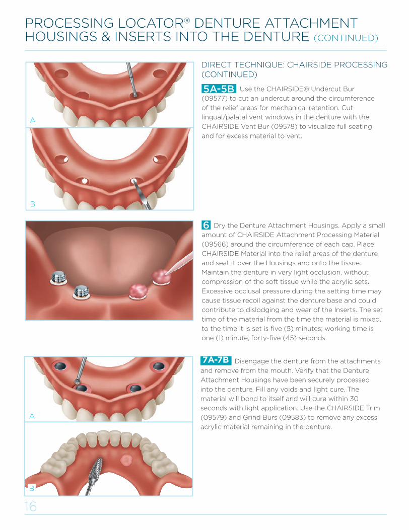
Disengage the denture from the attachments
and remove from the mouth. Verify that the Denture
Attachment Housings have been securely processed
into the denture. Fill any voids and light cure. The
material will bond to itself and will cure within 30
seconds with light application. Use the CHAIRSIDE Trim
(09579) and Grind Burs (09583) to remove any excess
acrylic material remaining in the denture.
7A-7B
A
B
PROCESSING LOCATOR® DENTURE ATTACHMENT HOUSINGS & INSERTS INTO THE DENTURE (CONTINUED)
Dry the Denture Attachment Housings. Apply a small
amount of CHAIRSIDE Attachment Processing Material
(09566) around the circumference of each cap. Place
CHAIRSIDE Material into the relief areas of the denture
and seat it over the Housings and onto the tissue.
Maintain the denture in very light occlusion, without
compression of the soft tissue while the acrylic sets.
Excessive occlusal pressure during the setting time may
cause tissue recoil against the denture base and could
contribute to dislodging and wear of the Inserts. The set
time of the material from the time the material is mixed,
to the time it is set is five (5) minutes; working time is
one (1) minute, forty-five (45) seconds.
Use the CHAIRSIDE® Undercut Bur
(09577) to cut an undercut around the circumference
of the relief areas for mechanical retention. Cut
lingual/palatal vent windows in the denture with the
CHAIRSIDE Vent Bur (09578) to visualize full seating
and for excess material to vent.
DIRECT TECHNIQUE: CHAIRSIDE PROCESSING(CONTINUED)
5A-5B
B
A
L8019-TM_LODI Manual_REVE.indd 17 29/09/2015 16:09:10
17
PROCESSING LOCATOR® DENTURE ATTACHMENT HOUSINGS & INSERTS INTO THE DENTURE (CONTINUED)
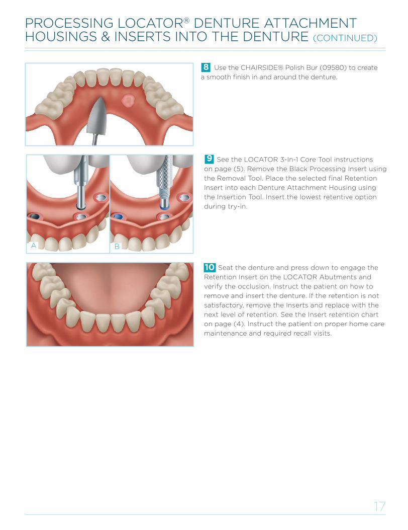
Seat the denture and press down to engage the
Retention Insert on the LOCATOR Abutments and
verify the occlusion. Instruct the patient on how to
remove and insert the denture. If the retention is not
satisfactory, remove the Inserts and replace with the
next level of retention. See the Insert retention chart
on page (4). Instruct the patient on proper home care
maintenance and required recall visits.
FPO
FPO
A B
10
See the LOCATOR 3-In-1 Core Tool instructions
on page (5). Remove the Black Processing Insert using
the Removal Tool. Place the selected final Retention
Insert into each Denture Attachment Housing using
the Insertion Tool. Insert the lowest retentive option
during try-in.
9
Use the CHAIRSIDE® Polish Bur (09580) to create
a smooth finish in and around the denture.
8
L8019-TM_LODI Manual_REVE.indd 18 29/09/2015 16:09:11
18
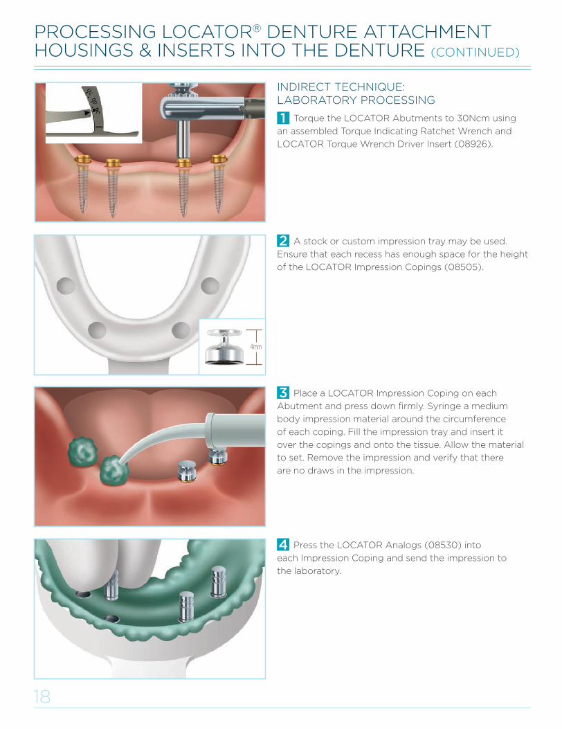
A stock or custom impression tray may be used.
Ensure that each recess has enough space for the height
of the LOCATOR Impression Copings (08505).
4mm
Place a LOCATOR Impression Coping on each
Abutment and press down firmly. Syringe a medium
body impression material around the circumference
of each coping. Fill the impression tray and insert it
over the copings and onto the tissue. Allow the material
to set. Remove the impression and verify that there
are no draws in the impression.
Press the LOCATOR Analogs (08530) into
each Impression Coping and send the impression to
the laboratory.
Torque the LOCATOR Abutments to 30Ncm using
an assembled Torque Indicating Ratchet Wrench and
LOCATOR Torque Wrench Driver Insert (08926).
INDIRECT TECHNIQUE: LABORATORY PROCESSING
FPO
L8019-TM_LODI Manual_REVE.indd 19 29/09/2015 16:09:11
8
19
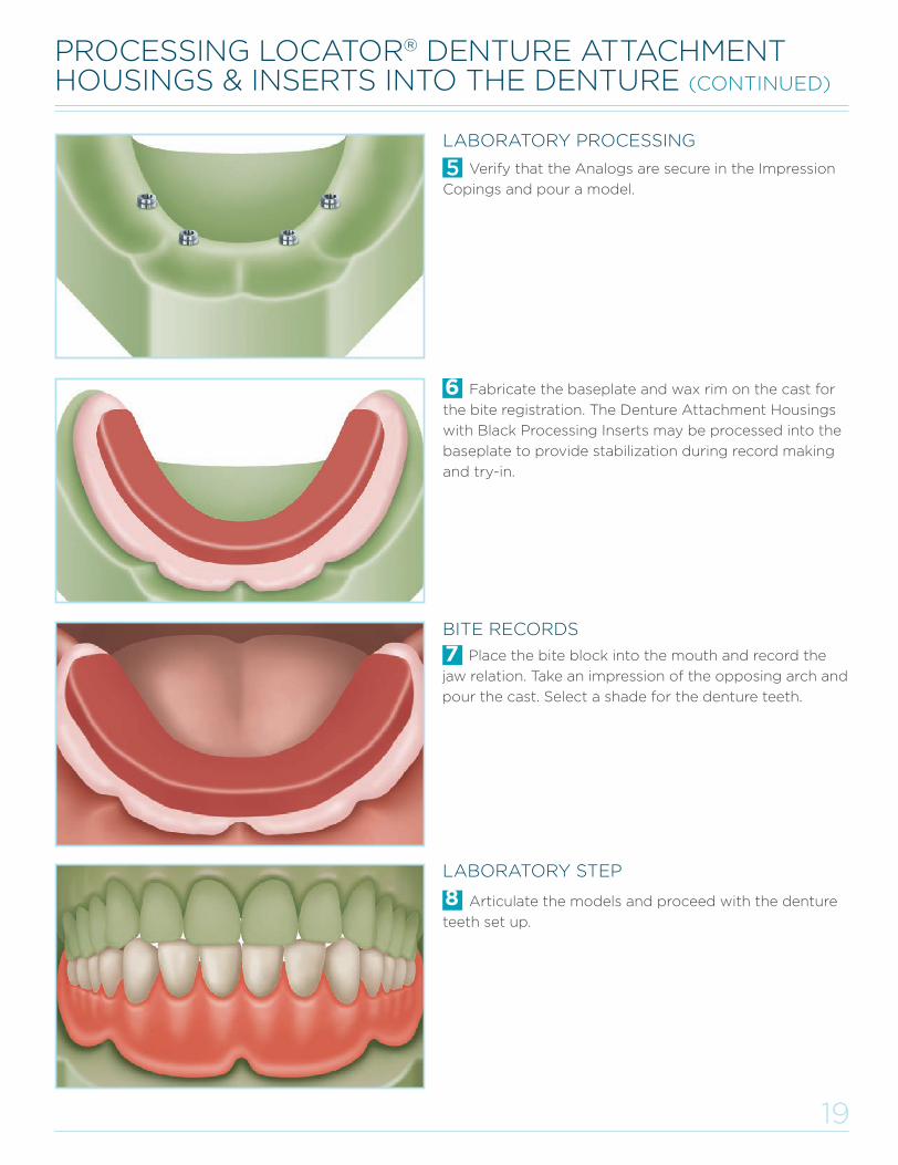
Verify that the Analogs are secure in the Impression
Copings and pour a model.
LABORATORY PROCESSING
BITE RECORDS
Place the bite block into the mouth and record the
jaw relation. Take an impression of the opposing arch and
pour the cast. Select a shade for the denture teeth.
Articulate the models and proceed with the denture
teeth set up.
LABORATORY STEP
Fabricate the baseplate and wax rim on the cast for
the bite registration. The Denture Attachment Housings
with Black Processing Inserts may be processed into the
baseplate to provide stabilization during record making
and try-in.
6
7
L8019-TM_LODI Manual_REVE.indd 20 29/09/2015 16:09:12
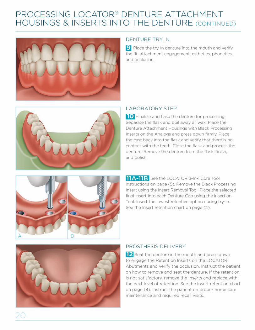
Seat the denture in the mouth and press down
to engage the Retention Inserts on the LOCATOR
Abutments and verify the occlusion. Instruct the patient
on how to remove and seat the denture. If the retention
is not satisfactory, remove the Inserts and replace with
the next level of retention. See the Insert retention chart
on page (4). Instruct the patient on proper home care
maintenance and required recall visits.
Finalize and flask the denture for processing.
Separate the flask and boil away all wax. Place the
Denture Attachment Housings with Black Processing
Inserts on the Analogs and press down firmly. Place
the cast back into the flask and verify that there is no
contact with the teeth. Close the flask and process the
denture. Remove the denture from the flask, finish,
and polish.
Place the try-in denture into the mouth and verify
the fit, attachment engagement, esthetics, phonetics,
and occlusion.
See the LOCATOR 3-In-1 Core Tool
instructions on page (5). Remove the Black Processing
Insert using the Insert Removal Tool. Place the selected
final Insert into each Denture Cap using the Insertion
Tool. Insert the lowest retentive option during try-in.
See the Insert retention chart on page (4).
11A-11B
10
12
9
20
A B
PROSTHESIS DELIVERY
LABORATORY STEP
DENTURE TRY IN
L8019-TM_LODI Manual_REVE.indd 21 29/09/2015 16:09:13
21
INDICATIONSThe LOCATOR® Overdenture Implant System is
designed to retain overdentures or partial dentures
in the mandible or maxilla.
CONTRAINDICATIONSNot appropriate where a totally rigid connection is
required. Use of a single implant with divergence
greater than 20° is not recommended. Dental implants
should not be used in patients with serious medical
problems or in a poor general state of health. Patients
with medical problems such as: uncontrolled bleeding
disorders, drug or alcohol abuse, weakened immune
system, titanium allergy or uncontrollable endocrine
disorders should be carefully evaluated prior to
treatment.
CAUTIONFederal (U.S.A.) law restricts this device to sale by
or on the order of a licensed dentist.
STORAGE AND HANDLINGThe LOCATOR Overdenture Implant System in its
undamaged, original packaging is not subject to
any special considerations for storage or handling
(during transport and storage). Only sterile titanium
or stainless instruments/tools should be used to
handle and deliver the implant to the surgical site.
SINGLE-USE DEVICESThe LOCATOR Overdenture Implant System is a
single-use device.
LOCATOR Overdenture Implant: A previously used
LOCATOR Overdenture Implant could contain patient
contamination build-up. Therefore, the inadvertent
re-use of this device could result in infection leading
to lack of integration (of the implant to the bone).
LOCATOR Retention Inserts: The inadvertent re-
use of LOCATOR Retention Inserts could cause loss
of retention of the overdenture due to wear from
previous use or damage during removal with the
LOCATOR Core Tool.
LOCATOR Abutments: The inadvertent re-use
of LOCATOR Abutments could contain patient
contamination build-up and subsequent wear of the
retention features. This would result in the device to
perform with improper fit and function which would
result in loss of retention of the prosthesis.
STERILIZATIONThe LOCATOR Overdenture Implant is packaged with
the LOCATOR Abutment and together are supplied
STERILE (subjected to radiation (gamma) as a means
of sterilization).
All other restorative components, instruments, and
replacement LOCATOR Abutments (sold separately)
are supplied NON-STERILE.
The nylon Retention Inserts may be sterilized/
disinfected using a liquid chemical sterilant. In order to
ensure that the nylon Inserts are sterilized/disinfected
(all microorganisms including Clostridium sporogenes
and Bacillus subtilis spores are eliminated), the nylon
Retention Inserts must be soaked for a minimum of
3 hours in the liquid sterilant at room temperature.
Note: An FDA approved liquid chemical sterilant for
critical devices that are heat-sensitive and incompatible
with sterilization methods such as steam and gas/
vapor/plasma low temperature processes may be
used following the manufacturer’s directions for the
sterilization (not just high-level disinfection) of the
device.
IMPORTANT INFORMATION ABOUT THE LODI SYSTEM & SURGICAL INSTRUMENTATION
CLEANING INSTRUCTIONS FOR INSTRUMENTS AND INDIVIDUALLY PACKAGED REPLACEMENT ATTACHMENTS
Disassemble any instruments that can be
disassembled according to manufacturers’ instructions.
Soak instruments in enzymatic cleaning solution
(mixed according to manufacturers’ instructions) by
completely submerging them for 20 minutes. Scrub
instruments using a soft-bristled, nylon brush until all
soil has been removed.
Remove the instruments from the enzymatic
cleaning solution and rinse in tap water for a
minimum of 3 minutes. Make sure to thoroughly flush
internal holes/crevices of instruments (such as the
tissue punch, drill extender, implant drivers, and
disassembled core tool and ratchet torque wrench)
that have difficult to reach areas.
Note: Use of a syringe or water jet will improve
flushing of difficult to reach areas.
L8019-TM_LODI Manual_REVE.indd 22 29/09/2015 16:09:13
22
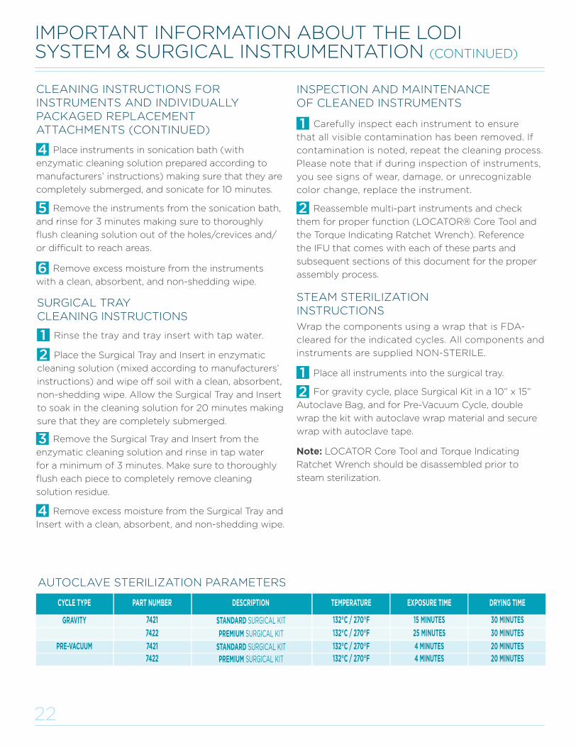
PRE-VACUUM STANDARD SURGICAL KITPREMIUM SURGICAL KIT
74217422
4 MINUTES4 MINUTES
132°C / 270°F132°C / 270°F
20 MINUTES20 MINUTES
STANDARD SURGICAL KITPREMIUM SURGICAL KIT
7421
7422
15 MINUTES
25 MINUTES
132°C / 270°F
132°C / 270°F
30 MINUTES
30 MINUTESGRAVITY
CYCLE TYPE DESCRIPTIONPART NUMBER EXPOSURE TIMETEMPERATURE DRYING TIME
IMPORTANT INFORMATION ABOUT THE LODI SYSTEM & SURGICAL INSTRUMENTATION (CONTINUED)
INSPECTION AND MAINTENANCE OF CLEANED INSTRUMENTS
Carefully inspect each instrument to ensure
that all visible contamination has been removed. If
contamination is noted, repeat the cleaning process.
Please note that if during inspection of instruments,
you see signs of wear, damage, or unrecognizable
color change, replace the instrument.
Reassemble multi-part instruments and check
them for proper function (LOCATOR® Core Tool and
the Torque Indicating Ratchet Wrench). Reference
the IFU that comes with each of these parts and
subsequent sections of this document for the proper
assembly process.
CLEANING INSTRUCTIONS FORINSTRUMENTS AND INDIVIDUALLY PACKAGED REPLACEMENT ATTACHMENTS (CONTINUED)
Place instruments in sonication bath (with
enzymatic cleaning solution prepared according to
manufacturers’ instructions) making sure that they are
completely submerged, and sonicate for 10 minutes.
Remove the Surgical Tray and Insert from the
enzymatic cleaning solution and rinse in tap water
for a minimum of 3 minutes. Make sure to thoroughly
flush each piece to completely remove cleaning
solution residue.
Remove excess moisture from the Surgical Tray and
Insert with a clean, absorbent, and non-shedding wipe.
SURGICAL TRAY CLEANING INSTRUCTIONS
Rinse the tray and tray insert with tap water.
Place the Surgical Tray and Insert in enzymatic
cleaning solution (mixed according to manufacturers’
instructions) and wipe off soil with a clean, absorbent,
non-shedding wipe. Allow the Surgical Tray and Insert
to soak in the cleaning solution for 20 minutes making
sure that they are completely submerged.
Remove the instruments from the sonication bath,
and rinse for 3 minutes making sure to thoroughly
flush cleaning solution out of the holes/crevices and/
or difficult to reach areas.
Remove excess moisture from the instruments
with a clean, absorbent, and non-shedding wipe.
STEAM STERILIZATION INSTRUCTIONS
Wrap the components using a wrap that is FDA-
cleared for the indicated cycles. All components and
instruments are supplied NON-STERILE.
Place all instruments into the surgical tray.
For gravity cycle, place Surgical Kit in a 10” x 15”
Autoclave Bag, and for Pre-Vacuum Cycle, double
wrap the kit with autoclave wrap material and secure
wrap with autoclave tape.
Note: LOCATOR Core Tool and Torque Indicating
Ratchet Wrench should be disassembled prior to
steam sterilization.
AUTOCLAVE STERILIZATION PARAMETERS
L8019-TM_LODI Manual_REVE.indd 23 29/09/2015 16:09:13
23
TORQUE INDICATING RATCHET WRENCH CLEANING PROCEDURES
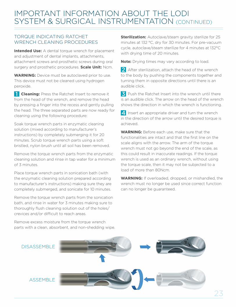
DISASSEMBLE
ASSEMBLE
Cleaning: Press the Ratchet Insert to remove it
from the head of the wrench, and remove the head
by pressing a finger into the recess and gently pulling
the head. The three separated parts are now ready for
cleaning using the following procedure:
Soak torque wrench parts in enzymatic cleaning
solution (mixed according to manufacturer’s
instructions) by completely submerging it for 20
minutes. Scrub torque wrench parts using a soft
bristled, nylon brush until all soil has been removed.
Remove the torque wrench parts from the enzymatic
cleaning solution and rinse in tap water for a minimum
of 3 minutes.
Place torque wrench parts in sonication bath (with
the enzymatic cleaning solution prepared according
to manufacturer’s instructions) making sure they are
completely submerged, and sonicate for 10 minutes.
Remove the torque wrench parts from the sonication
bath, and rinse in water for 3 minutes making sure to
thoroughly flush cleaning solution out of the holes/
crevices and/or difficult to reach areas.
Remove excess moisture from the torque wrench
parts with a clean, absorbent, and non-shedding wipe.
Intended Use: A dental torque wrench for placement
and adjustment of dental implants, attachments,
attachment screws and prosthetic screws during oral
surgery and prosthetic procedures. Scale Unit: Ncm.
WARNING: Device must be autoclaved prior to use.
This device must not be cleaned using hydrogen
peroxide.
Sterilization: Autoclave/steam gravity sterilize for 25
minutes at 132 °C, dry for 30 minutes. For pre-vacuum
cycle, autoclave/steam sterilize for 4 minutes at 132°C
with drying time of 20 minutes.
Note: Drying times may vary according to load.
After sterilization, attach the head of the wrench
to the body by pushing the components together and
turning them in opposite directions until there is an
audible click.
Push the Ratchet Insert into the wrench until there
is an audible click. The arrow on the head of the wrench
shows the direction in which the wrench is functioning.
Insert an appropriate driver and turn the wrench
in the direction of the arrow until the desired torque is
achieved.
WARNING: Before each use, make sure that the
functionalities are intact and that the first line on the
scale aligns with the arrow. The arm of the torque
wrench must not go beyond the end of the scale, as
this could result in inaccurate readings. If the torque
wrench is used as an ordinary wrench, without using
the torque scale, then it may not be subjected to a
load of more than 80Ncm.
WARNING: If overloaded, dropped, or mishandled, the
wrench must no longer be used since correct function
can no longer be guaranteed.
IMPORTANT INFORMATION ABOUT THE LODI SYSTEM & SURGICAL INSTRUMENTATION (CONTINUED)
IMPORTANT INFORMATION ABOUT THE LODI SYSTEM & SURGICAL INSTRUMENTATION (CONTINUED)
L8019-TM_LODI Manual_REVE.indd 24 29/09/2015 16:09:13
24
WARNINGS AND PRECAUTIONSThe LOCATOR® Overdenture Implant System has not
been evaluated for safety and compatibility in the
MR environment. It has not been tested for heating,
migration, or image artifact in the MR environment.
The safety of the LOCATOR Overdenture Implant
System in the MR environment is unknown. Scanning
a patient who has this device may result in patient
injury.
Product (implant/attachment) from damaged
sterilized packaging must not be used on patients.
In the event that the sterilized packaging for the
LOCATOR Overdenture Implant System is damaged,
the damaged packaging (with the product) must be
returned to the manufacturer and a replacement will
be provided (if damage to sterilized packaging is
caused by product shipment).
The drill extender is to be used with surgical
drills only and should not be used in high torque
applications.
Avoid application of excessive bending load on
smaller diameter drills during drilling. Drills will
dull based on many factors including bone density,
handling, autoclave exposure, etc. Replace drills
when wear is noticeable to avoid excessive heat
being transferred to surrounding bone during
osteotomy preparation.
Do not use the LOCATOR Abutment on top of the
implant to further advance the implant into the
osteotomy. If the implant needs to be placed deeper,
remove the Abutment, re-engage the Implant Driver
onto the implant and ratchet to desired depth.
If the LOCATOR Overdenture Implant System is
subjected to inappropriate loading conditions, there
may be a potential risk of metal fatigue or localized
bone failure. The use of other tissue grafting
components or parts that are made from dissimilar
metals should not be used in or near the implant.
Patient evaluation including the determination of
the general health, oral hygiene habits and status,
motivation toward good dental care, and anatomic
acceptability prior to implant surgery is critical.
Thorough evaluation of the patient’s medical status
and health history is mandatory. Panoramic and
periapical radiographs as well as thorough oral
inspection and palpation are recommended to
determine anatomic landmarks, dental pathology,
and adequacy of bone. A cephalogram is suggested
for totally edentulous patients. Any oral condition
that adversely affects natural teeth, if uncorrected,
will have an adverse effect on the implants.
Periodontal disease, abnormal bone conditions,
severe bruxism, cross-bite situations, and extenuating
circumstances (e.g. excessive smoking, medical issues,
etc) that may adversely affect the procedure must
be evaluated and corrected if necessary, or use of the
implant may be contraindicated.
Based on the results of the patient’s pre-surgical
assessment, the clinician should select and order
the appropriate implant (determine correct
implant diameter and length based on bone
type), restorative parts, and tools. Refer to Drilling
Sequence section for further details. The clinician
should also determine if the patient is allergic to any
of the materials that will be used in the procedure as
part of the pre-surgical treatment planning. If during
patient evaluation, insufficient bone width, abnormal
bone defects or contours are detected, then the
placement of the implant may be contraindicated.
Patient motivation is a key factor in achieving
success with any implant. The patient must be
willing to practice the oral hygiene necessary for
implant maintenance. The clinician must provide
the patient with information regarding proper care
and maintenance of the implants. Also, they must
inform the patient that conditions such as excessive
smoking, improper/lack of maintenance may have
adverse effects.
The use of this or any surgical implant product
requires that the clinician be thoroughly familiar
with the product and the method for its use and
application. They must also be familiar with all the
instruments, and surgical procedures required
(as described in this document). The clinician must
also use reasonable judgment in deciding when
and where to use the product.
IMPORTANT INFORMATION ABOUT THE LODI SYSTEM & SURGICAL INSTRUMENTATION (CONTINUED)
L8019-TM_LODI Manual_REVE.indd 25 29/09/2015 16:09:13
25
To reduce wear on LOCATOR® Abutments
it is critical that clinicians and patients perform
routine maintenance on both the LOCATOR
Abutment, the Denture Attachment Housing and the
Retention Insert. It is also important that patients
understand the proper overdenture maintenance that
should be performed at home to guard
against retention loss of the Retention Inserts within
the Denture Attachment Housing.
The following are guidelines to consider.
INSERTING AND REMOVING AN OVERDENTURE To insert the overdenture, the patient should
ensure he/she can feel that it is properly positioned
above the LOCATOR Abutments prior to applying
pressure. The patient should use both hands and
simultaneously press down on each side to firmly
snap the overdenture into place.
The patient should avoid biting the overdenture
into place as this force will result in improper wear of
the LOCATOR Abutment and may affect the longevity
of the prosthesis.
The patient should remove the overdenture by
placing one thumb under the left edge and one finger
under the right edge of the overdenture rim and
pull one side upward and the other side downward,
simultaneously. They may also use their tongue to
aid in removal of the lower overdenture. Once the
overdenture is removed, a thorough cleaning is
recommended.
CLEANING AN OVERDENTURE Maintaining proper hygiene is vital to the success of
an overdenture, helping it last longer and function
properly. Similar to natural teeth, dental plaque will
also form on the surface of an overdenture. If the
plaque is not removed it will continue to accumulate.
It is for this reason that the overdenture should
be taken out for cleaning daily. Patients should
follow these two simple steps daily for cleaning an
overdenture.
Fill a washing basin with warm water to prevent
fracture of the overdenture. Apply detergent onto
a soft bristle toothbrush and thoroughly clean every
surface of the overdenture.
OVERDENTURE INSERTION, REMOVAL, AND CLEANING GUIDELINES FOR THE CLINICIAN AND PATIENT
Before bed each night, remove the overdenture and
immerse in a cup of plain cold water.
ADDITIONAL NOTES OF CAUTION Failure of the patient to follow oral hygiene protocols
and appropriately care for the overdenture may also
result in inflamed tissue around the implant, leading to
the development of peri-implantitis. Throughout time,
peri-implantitis may cause the implant to become
mobile and fail. Please ask patients to consider the
following when caring for their overdentures:
• Avoid using abrasive toothpaste to clean the
overdenture. The coarse particles in the toothpaste may
scratch the surfaces of the overdenture, enhancing the
potential for plaque accumulation.
• Chewing tobacco will get caught in the Retention
Inserts and scratch the Abutments, considerably
reducing the life of the Abutments, retentive features
of the Retention Inserts and ultimately may affect the
dental implants.
• Do not soak the overdenture in bleach or any other
products not designed for use with denture cleaning as
these can harm the retentive feature of the Retention
Insert, which may ultimately cause additional wear on
the Abutment.
• If a denture cleaning solution such as Polident®
and Efferdent® must be used, it is recommended that
the denture be soaked for fifteen minutes or less.
• Brushing the Abutments increases wear; if the
patient brushes their Abutments, they should visit the
dentist for regular inspection and maintenance of the
Abutments, Retention Inserts and Attachment Housings.
• Refrain from picking at the Abutments or Retention
Inserts with toothpicks or other foreign objects.
• Refrain from eating without the overdenture in place
as food will scratch the Abutment or Retention Insert
and may result in failure of the dental implant. Food
trapped in the Abutment’s drive cavity can also result in
improper seating.
• Oral rinse such as Listerine® mouthwash can be used
safely without any poor effect on the Abutments or
Retention Inserts.
• Do not wash the overdenture in the dishwasher.
L8019-TM_LODI Manual_REVE.indd 26 29/09/2015 16:09:13
26
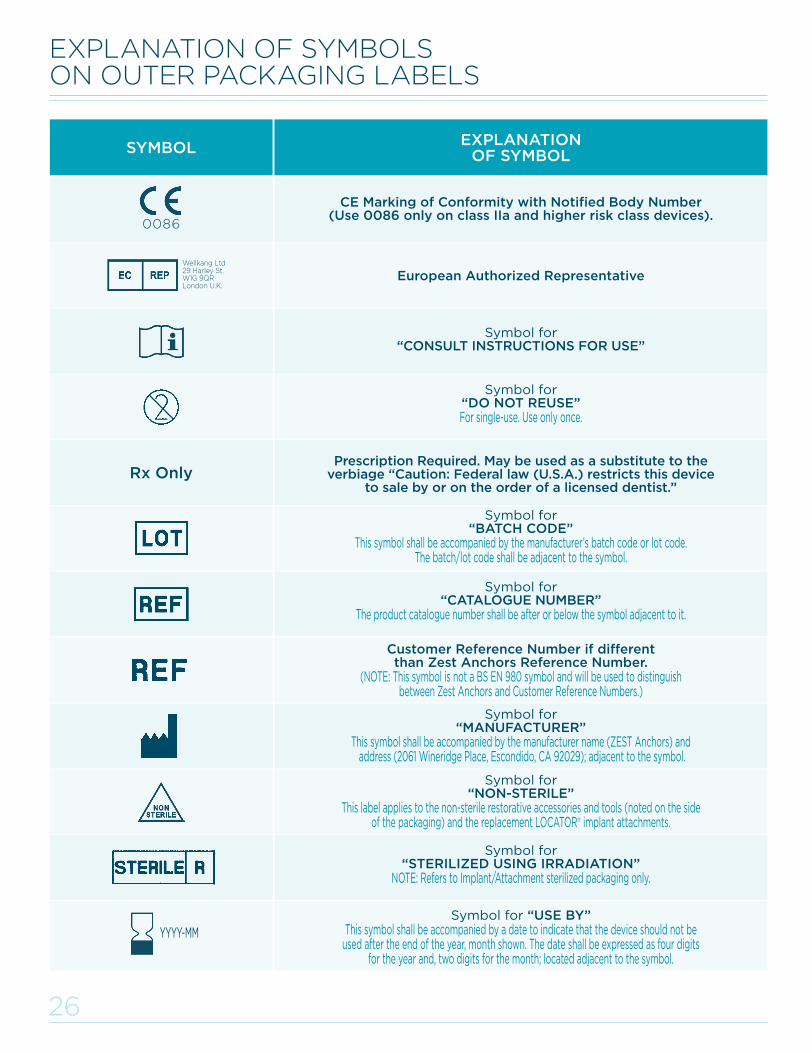
EXPLANATION OF SYMBOLS ON OUTER PACKAGING LABELS
Rx Only
EXPLANATION OF SYMBOLSYMBOL
CE Marking of Conformity with Notified Body Number (Use 0086 only on class IIa and higher risk class devices).
European Authorized Representative
Symbol for“DO NOT REUSE”For single-use. Use only once.
Symbol for “CONSULT INSTRUCTIONS FOR USE”
Prescription Required. May be used as a substitute to the verbiage “Caution: Federal law (U.S.A.) restricts this device
to sale by or on the order of a licensed dentist.”
Symbol for “BATCH CODE”
This symbol shall be accompanied by the manufacturer’s batch code or lot code. The batch/lot code shall be adjacent to the symbol.
Symbol for “CATALOGUE NUMBER”
The product catalogue number shall be after or below the symbol adjacent to it.
Customer Reference Number if different than Zest Anchors Reference Number.
(NOTE: This symbol is not a BS EN 980 symbol and will be used to distinguish between Zest Anchors and Customer Reference Numbers.)
Symbol for “MANUFACTURER”
This symbol shall be accompanied by the manufacturer name (ZEST Anchors) and address (2061 Wineridge Place, Escondido, CA 92029); adjacent to the symbol.
Symbol for “NON-STERILE”
This label applies to the non-sterile restorative accessories and tools (noted on the side of the packaging) and the replacement LOCATOR® implant attachments.
Symbol for “STERILIZED USING IRRADIATION”
NOTE: Refers to Implant/Attachment sterilized packaging only.
Symbol for “USE BY”This symbol shall be accompanied by a date to indicate that the device should not be
used after the end of the year, month shown. The date shall be expressed as four digits for the year and, two digits for the month; located adjacent to the symbol.
0086
YYYY-MM
Wellkang Ltd29 Harley St.W1G 9QRLondon U.K.
L8019-TM_LODI Manual_REVE.indd 27 29/09/2015 16:09:13
27
THE ZEST ANCHORS LLC NARROW DIAMETER IMPLANT (“NDI”) WARRANTY: LOCATOR® OVERDENTURE IMPLANT (“LODI”) AND SATURNO™ NARROW DIAMETER IMPLANT (“SNDI”)
ZEST Anchors LLC (“ZEST”) is committed to providing quality products and dedicated to gathering feedback about its products. ZEST actively collects and reviews the feedback of users of our products in compliance with regulatory reporting requirements and to better help us understand market expectations and validate our products’ performance. The collection method ZEST utilizes for such feedback is the ZEST Product Experience Report (“PER”) form. The PER form is to be completed from information provided by the attending clinician to share their ZEST product experience.
Pursuant to the ZEST NDI WARRANTY, ZEST will replace covered LODI and SNDI products for a $25 processing fee for each such qualifying covered implant that is returned (as such terms are defined below). Upon a request for replacement under the ZEST NDI WARRANTY, ZEST will send a replacement product once ZEST receives the returned product and completed PER form and confirms that the returned product is covered under the ZEST NDI WARRANTY. Upon shipment of the replacement product, ZEST will issue the customer an invoice at $25.
ONLY DIRECT ZEST CUSTOMERS MAY MAKE A WARRANTY CLAIM. In order to make a claim under the ZEST NDI WARRANTY please return the items mentioned below in protective packaging and send these via a shipping method which enables the package to be tracked:
Printed copy of PER form completed from information provided by the attending clinician.
Explanted product(s) in sterile condition (NON-STERILE products will not qualify for replacement)
If a product failure or loss of integration has occurred, please additionally send relevant radiographs (these will not be returned unless specifically requested, please send copies)
Send shipment to: ZEST ANCHORS LLC ATTN: Customer Service (US customers) or Wholesale Distribution (Distributors/OEM Partners) 2061 Wineridge Place Escondido, CA 92029
If using the electronic form, please include the Tracking Number for the returned product package.
Download ZEST NDI Product Experience Report (PDF) AT WWW.ZESTACHORS.COM
ZEST ANCORS (“ZEST”) NARROW DIAMETER IMPLANT (“NDI”) WARRANTY (Valid as of May 1, 2015)
1. Warranty beneficiary and scope: ZEST Anchors LLC hereby warrants to the direct ZEST customer purchasing the NDI from ZEST (“Customer”) that the ZEST LOCATOR Overdenture Implant (“LODI”) and SATURNO Narrow Diameter Implant (“SNDI”), when implanted according to the respective ZEST LODI/SNDI Technique Manual and other written instructions provided by ZEST by a clinician (the “User”), will be free from any loss or lack of integration, fracture or other structural failure for the period of 10 years (“Warranty Period”) from the time of treatment by the User (collectively, the “ZEST NDI WARRANTY”). This warranty only applies to the Customer. Third parties, particularly patients, are not covered by the ZEST NDI WARRANTY and have no rights hereunder. Customers’ sole remedy and ZEST’S sole liability under this ZEST NDI WARRANTY is the replacement of the LODI/SNDI implant by ZEST as set forth herein. The ZEST NDI WARRANTY only covers the replacement of the LODI/SNDI implant and not any associated costs or expenses, including, but not limited to, chair time, laboratory fees and any other associated treatment.
2. ZEST Warranty conditions: In the event that any request for warranty service for an NDI is made by a Customer under the ZEST NDI WARRANTY during the Warranty Period, ZEST will replace such NDI with the same or substantially equivalent product subject to the terms and conditions herein. The replacement product will be sent upon receipt of the returned product and the completed PER form and confirmation that the product is covered
THE ZEST ANCHORS 10 YEAR WARRANTY
under the ZEST NDI WARRANTY. To qualify for coverage under the ZEST NDI WARRANTY, the claim must be made within the applicable Warranty Period by a Customer and all conditions below must be met. Once these requirements are satisfied, ZEST will send the replacement part(s) and charge the ZEST Customer a $25 processing fee per unit. The following REQUIRED conditions must be met and documented in order for coverage of a returned NDI under this ZEST NDI WARRANTY:
1. The LODI/SNDI was used exclusively with all components, connections, attachments and other technology provided by ZEST and not in combination with any other manufacturer’s products or technology;
2. The LODI/SNDI is returned in sterile condition (or disinfected if delivered as such);
3. The LODI/SNDI was implanted by a User and inspected and maintained in full compliance with the respective ZEST LODI/SNDI Technique Manual valid at the time of treatment and all other ZEST written instructions as well as recognized dental procedures, during and after the treatment;
4. The patient had good oral hygiene which was monitored and documented by the User
5. The LODI/SNDI was not subjected to damage caused by misuse, misapplication, accident, trauma or any other damage caused by external factors or the User, the patient or a third party;
6. A completed and signed PER was completed and submitted no later than 10 days after the complaint is made. Customer is responsible to ensure that the PER is completed and submitted from information provided by the applicable User. Details of the incident are imperative to determine whether vigilance reporting is required to regulatory authorities.
3. Limits and limitations: This ZEST NDI WARRANTY is the only guarantee provided by ZEST and shall apply in addition to any warranty rights conferred under any written sales agreement executed by ZEST. The User remains free to claim rights against his supplier. EXCEPT AS SET FORTH HEREIN AND IN A WRITTEN SALES AGREEMENT EXECUTED BY ZEST, ZEST HEREBY DISCLAIMS ANY OTHER WARRANTIES, EXPRESS OR IMPLIED, WITH RESPECT TO LODI/SNDI OR ANY OTHER ZEST PRODUCTS, SERVICES OR INFORMATION, INCLUDING, BUT NOT LIMITED TO, ANY WARRANTY OF FITNESS FOR PURPOSE OR MERCHANTABILITY, OR NON-INFRINGEMENT OF THIRD PARTY RIGHTS, OR ANY WARRANTY BY COURSE OF PERFORMANCE OR OTHERWISE.
ZEST SHALL NOT BE LIABLE TO THE CUSTOMER, THE USER, THE PATIENT, OR ANY THIRD PARTY, FOR LOST EARNINGS OR PROFITS, DIRECT OR INDIRECT DAMAGES AS WELL AS COLLATERAL, INCIDENTAL, PUNITIVE OR CONSEQUENTIAL DAMAGES, DIRECTLY OR INDIRECTLY RELATED TO LODI OR ANY OTHER ZEST PRODUCTS, SERVICES OR INFORMATION.
4. ZEST Warranty territory: This ZEST NDI WARRANTY applies worldwide to LODI/SNDI implants sold by ZEST, a ZEST affiliated company or an official distributor of ZEST on or after the validity date stated above.
5. Modification or termination: ZEST may modify or terminate this ZEST NDI WARRANTY at any time in whole or in part. Changes to, or the termination of the ZEST NDI WARRANTY, will not affect the warranty given for LODI/SNDI installed prior to the date of the change or termination.
LOCATOR OVERDENTURE IMPLANT (LODI) and SATURNO NARROW DIAMETER IMPLANT (SNDI) PRODUCT EXCHANGE POLICY
ZEST Anchors LLC understands that customers may need to adjust inventories of LOCATOR Overdenture Implant (LODI) and SATURNO Narrow Diameter Implant (SNDI) Products in order to achieve the correct mix of sizes to treat their patients. ZEST Anchors LLC will waive normal restocking fees (1:1 or greater) for exchanges during the first six months following the original purchase. Packaging cannot be written on or in any way adulterated. Shipping will still be the responsibility of the customer requesting the exchange.
L8019-TM_LODI Manual_REVE.indd 28 29/09/2015 16:09:13
ZEST ANCHORS2061 WINERIDGE PLACEESCONDIDO, CA 92029USA
TEL: 1.855.868.LODI (5634)FAX: 760.743.7975EMAIL: [email protected]
DISTRIBUTED BY:
©2015 ZEST Anchors LLC. All rights reserved. CHAIRSIDE, Color and Shape of Retention Inserts,LOCATOR and ZEST are registered trademarks and SATURNO is a trademark of ZEST IP Holdings, LLC. Efferdent is a registered trademark of Blacksmith Brands, Inc.Listerine is a registered trademark of Johnson & Johnson. Polident is a registered trademark of Block Drug Company, Inc. L8019-TM REV E 06/2015
0086
VISIT OUR WEBSITE ATWWW.ZESTANCHORS.COMTO PLACE ORDERS ONLINE24 HOURS A DAY 7 DAYS A WEEK.
L8019-TM_LODI Manual_REVE.indd 29 29/09/2015 16:09:14

![FRP - StudiesToday.com Class 7... · History Picture Identification & discription- [10 Marks] Geography- Map ... Lodis Bahlul lodi Sikander Lodi Ibrahim Lodi](https://img.pdfslide.net/doc/110x75/5a9e2ce47f8b9a36788c4f5e/frp-class-7history-picture-identification-discription-10-marks-geography-.jpg)