Embed Size (px)
Citation preview
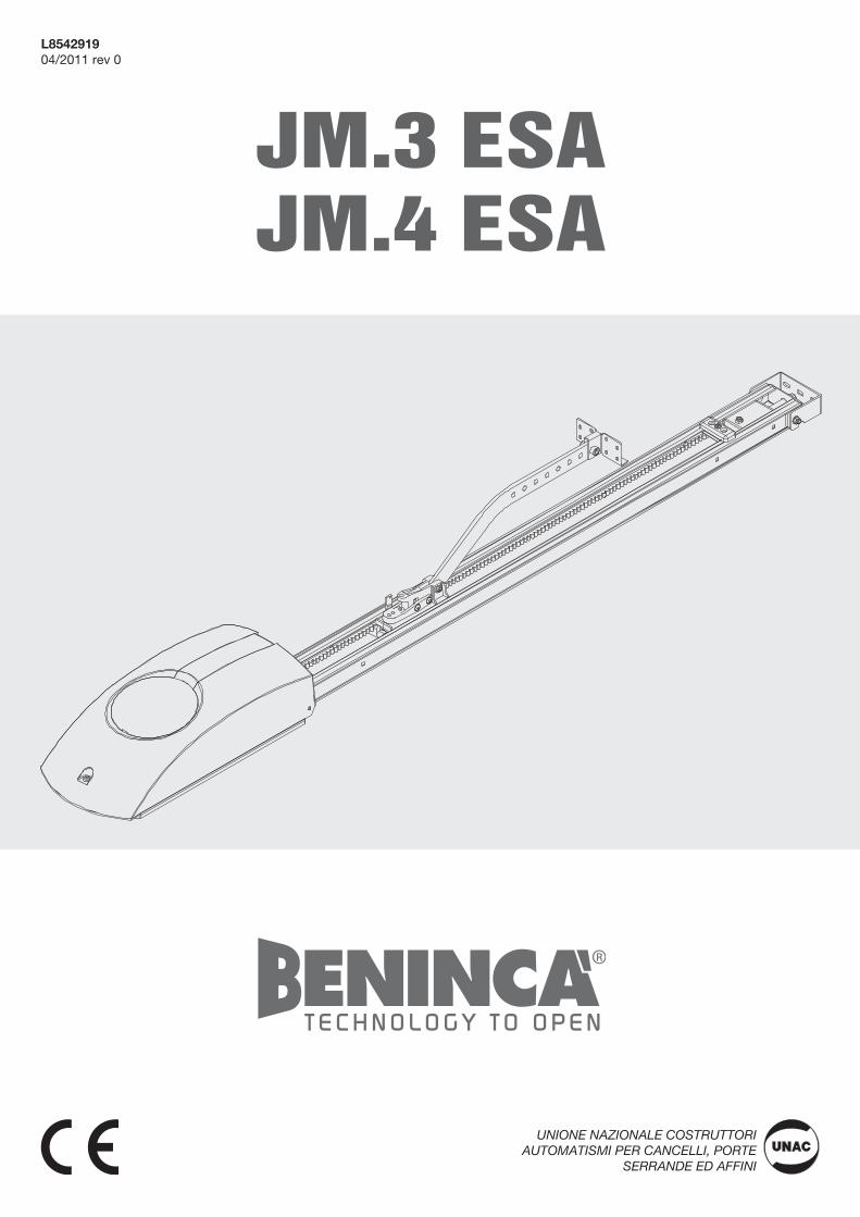
JM.3 ESAJM.4 ESA
L854291904/2011 rev 0
UNIONE NAZIONALE COSTRUTTORIAUTOMATISMI PER CANCELLI, PORTE
SERRANDE ED AFFINI

3
34
202446
PTC3 3024 / PTC4 3024
PTCL4 4024PTC3 2660 / P
TC4 2660
PTCL4 3660
1
2
min
. 40m
m
3
2+2 M6x16
R
D
F
F2+2 M6x16
R2
4+4 M6x16
P
P
R
D
4a
4b
4
5
D
M
M
R
R
S
S
6
7 8S
P
4,8x38
9 10
5
11 12
13a
V
K
13b
V
K
PTC.4 / PTCL.4AU.C25
MD
6
16 17
14
S
A
7
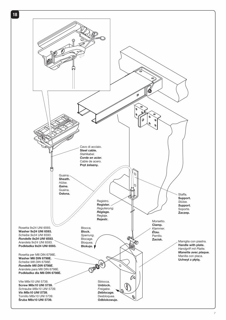
18
Cavo di acciaio.Steel cable.Stahlkabel.Corde en acier.Cable de acero.Pręt żelazny.
Guaina.Sheath.Hülse.Gaine.Guaina.Osłona.
Registro.Register.Regulierung.Réglage.Reglaje.Rejestr.
Staffa.Support.Stütze.Support.Soporte.Zaczep.
Morsetto.Clamp.Klammer.Étau.Perrillo.Zacisk.
Maniglia con piastra.Handle with plate.Handgriff mit Platte.Manette avec plaque.Manilla con placa.Uchwyt z płytą.
Blocca.Block.Sperrung.Blocage.Bloquea.Blokuje.
Sblocca.Unblock.Freigabe.Déblocage.Desbloquea.Odblokowuje.
Rosetta 9x24 UNI 6593.Washer 9x24 UNI 6593.Scheibe 9x24 UNI 6593.Rondelle 9x24 UNI 6593.Arandela 9x24 UNI 6593.Podkładka 9x24 UNI 6593.
Rosetta per M8 DIN 6798E.Washer M8 DIN 6798E.Scheibe M8 DIN 6798E.Rondelle M8 DIN 6798E.Arandela para M8 DIN 6798E.Podkładka dla M8 DIN 6798E.
Vite M8x10 UNI 5739.Screw M8x10 UNI 5739.Schraube M8x10 UNI 5739.Vis M8x10 UNI 5739.Tornillo M8x10 UNI 5739.Śruba M8x10 UNI 5739.
8
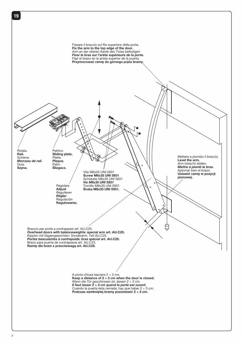
19
Mettere a piombo il braccio.Level the arm.Arm lotrecht stellen.Mettre à plomb le bras.Aplomar bien el brazo.Ustawić ramię w pozycji pionowej.
Braccio per porte a contrappesi art. AU.C25.Overhead doors with balanceweights: special arm art. AU.C25.Kipptor mit Gegengewichten: Sonderarm, Teil AU.C25.Portes basculantes à contrepoids: bras spécial art. AU.C25.Brazo para puerta de contrapesos art. AU.C25.Ramię dla bram z przeciwwagą art. AU.C25.
Rotaia.Rail.Schiene.Morceau de rail.Guía.Szyna.
Pattino.Sliding plate.Platte.Plaque.Patín.Ślizgacz.
RegolareAdjustRegulierenRéglerRegulaciónRegulowanie.
Vite M6x35 UNI 5931Screw M6x35 UNI 5931Schraube M6x35 UNI 5931Vis M6x35 UNI 5931Tornillo M6x35 UNI 5931Śruba M6x35 UNI 5931.
A porta chiusa lasciare 2 ÷ 3 cm.Keep a distance of 2 ÷ 3 cm when the door is closed.Wenn die Tür geschlossen ist, lassen 2 ÷ 3 cm.Il faut lasser 2 ÷ 3 cm quand la porte est ouvert.Cuando la puerta ésta cerrada, hay que haber 2 ÷ 3 cm.Podczas zamkniętej bramy pozostawić 2 ÷ 3 cm.
Fissare il braccio sul filo superiore della porta.Fix the arm to the top edge of the door.Arm an der oberen Kante des Tores befestigenFixer le bras sur l’arête supérieure de la porte.Fijar el brazo en la arista superior de la puerta.Przymocować ramię do górnego prętu bramy.
9
Dichiarazione CE di ConformitàDichiarazione in accordo alle Direttive 2004/108/CE(EMC); 2006/95/CE(LVD)
Fabbricante: Automatismi Benincà SpAIndirizzo: Via Capitello, 45 - 36066 Sandrigo (VI) - ItaliaDichiara che il prodotto: Automazione a traino per porte sezionali modello:JM.3 ESA/JM.4 ESA.è conforme alle condizioni delle seguenti Direttive CE:• DIRETTIVA 2004/108/CE DEL PARLAMENTO EUROPEO E DEL CONSIGLIO del 15 dicembre 2004 concernente il ravvici-namento delle legislazioni degli Stati membri relative alla compatibilità elettromagnetica e che abroga la direttiva 89/336/CEE, secondo le seguenti norme armonizzate: EN 61000-6-2:2005, EN 61000-6-3:2007.• DIRETTIVA 2006/95/CE DEL PARLAMENTO EUROPEO E DEL CONSIGLIO del 12 dicembre 2006 concernente il ravvicinamento delle legislazioni degli Stati membri relative al materiale elettrico destinato ad essere adoperato entro taluni limiti di tensione, secondo le seguenti norme armonizzate: EN 60335-1:2002 + A1:2004 + A11:2004 + A12:2006 + A2:2006 + A13:2008; EN 60335-2-103:2003.• DIRETTIVA 2006/42/CE DEL PARLAMENTO EUROPEO E DEL CONSIGLIO del 17 maggio 2006 relativa alle macchine e che modifica la direttiva 95/16/CE, rispettando i requisiti per le “quasi macchine”, secondo la seguente norma: EN13241-1:2003.• Automatismi Benincà SpA dichiara, inoltre, che la documentazione tecnica pertinente è stata compilata in conformità all’allegato VII B della direttiva 2006/42/CE e che sono stati rispettati i seguenti requisiti essenziali: 1.1.1 - 1.1.2 - 1.1.3 - 1.1.5 - 1.2.1 - 1.2.3 - 1.2.6 - 1.3.1 - 1.3.2 - 1.3.3 - 1.3.4 - 1.3.7 - 1.3.9 - 1.5.1 - 1.5.2 - 1.5.4 - 1.5.5 - 1.5.6 - 1.5.7 - 1.5.8 - 1.5.10 - 1.5.11 - 1.5.13 - 1.6.1 - 1.6.2 - 1.6.4 - 1.7.2 - 1.7.4 - 1.7.4.1 - 1.7.4.2 - 1.7.4.3.• Il produttore si impegna a trasmettere alle autorità nazionali, in risposta ad una motivata richiesta, le informazioni pertinenti sulla “quasi macchina”. L’impegno comprende le modalità di trasmissione e lascia impregiudicati i diritti di proprietà intellettuale del fabbricante della “quasi macchina”.• Si comunica che la “quasi macchina” non deve essere messa in servizio finché la macchina finale in cui deve essere incorporata non è stata dichiarata conforme, se del caso, alle disposizioni della direttiva 2006/42/CE.
• Inoltre il prodotto, limitatamente alle parti applicabili, risulta conforme alle seguenti norme:EN 12445:2002, EN 12453:2002, EN 12978:2003.
Benincà Luigi, Responsabile legale.Sandrigo, 02/11/2010.
E' vietato l'utilizzo del prodotto per scopi o con modalità non previste nel presente manuale. Usi non corretti posso-no essere causa di danni al prodotto e mettere in pericolo persone e cose.
Si declina ogni responsabilità dall'inosservanza della buona tecnica nella costruzione dei cancelli, nonché dalle defor-mazioni che potrebbero verificarsi durante l'uso.
Conservare questo manuale per futuri utilizzi.
L'installazione deve essere effettuata da personale quali-ficato nel pieno rispetto delle normative vigenti.
I materiali dell'imballaggio non devono essere lasciati alla portata dei bambini in quanto fonte di potenziale pericolo. Non disperdere nell'ambiente i materiali di imballo, ma se-parare le varie tipologie (es. cartone, polistirolo) e smaltirle secondo le normative locali.
L’installatore deve fornire tutte le informazioni relative al funzionamento automatico, manuale e di emergenza dell'automazione, e consegnare all’utilizzatore dell’impian-to le istruzioni d’uso.
AVVERTENZE
•Prevedere sulla rete di alimentazione un inter-ruttore/sezionatore onnipolare con distanza d’apertura dei contatti uguale o superiore a 3 mm.
Verificare che a monte dell’impianto elettrico vi sia un interrut-tore differenziale e una protezione di sovracorrente adeguati. Alcune tipologie di installazione richiedono il collegamento dell'anta ad un impianto di messa a terra rispondente alle vigenti norme di sicurezza.Durante gli interventi di installazione, manutenzione e ri-parazione, togliere l’alimentazione prima di accedere alle parti elettriche.
Le descrizioni e le illustrazioni presenti in questo manuale non sono impegnative. Lasciando inalterate le caratte-ristiche essenziali del prodotto il fabbricante si riserva il diritto di apportare qualsiasi modifica di carattere tecnico, costruttivo o commerciale senza impegnarsi ad aggiornare la presente pubblicazione.
10
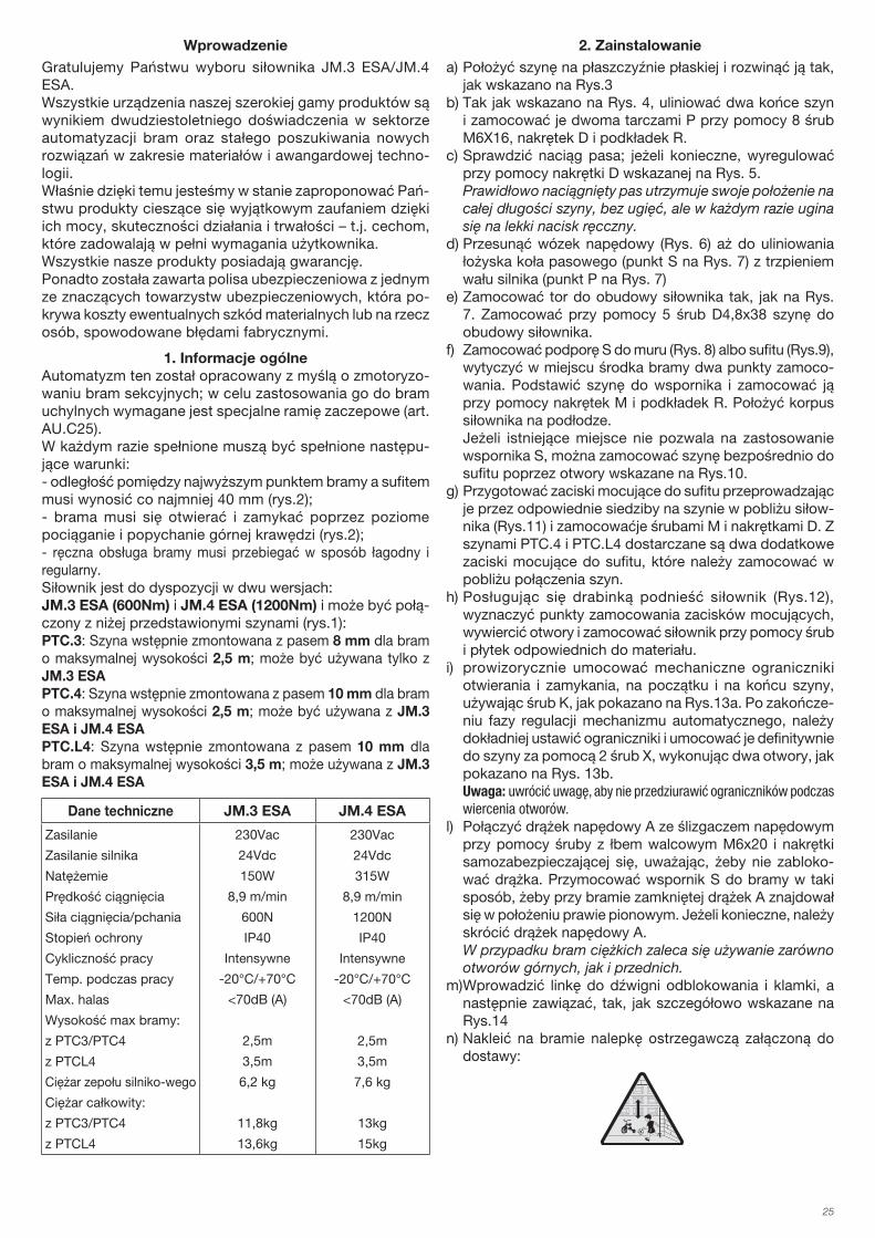
IntroduzioneCi congratuliamo con Voi per aver scelto il motoriduttore JM.3 ESA/JM.4 ESA.Tutti gli articoli della vasta gamma Benincà sono il frutto di una ventennale esperienza nel settore degli automatismi e di una continua ricerca di nuovi materiali e di tecnologie all’avanguardia.Proprio per questo, oggi siamo in grado di offrire dei prodotti estremamente affidabili che, grazie alla loro potenza, effica-cia e durata, soddisfano pienamente le esigenze dell’utente finale.Tutti i nostri prodotti sono coperti da garanzia.Inoltre, una polizza R. C. prodotti stipulata con primaria com-pagnia assicurativa copre eventuali danni a cose o persone causati da difetti di fabbricazione.
1. Notizie generaliL’automatismo è concepito per motorizzare porte sezionali; per essere applicato su porte basculanti necessita di uno speciale braccio di attacco (art. AU.C25).In ogni caso dovranno essere assolte le seguenti condizioni:- la distanza tra il punto più alto della porta ed il soffitto deve
essere almeno 40mm (fig.2);- la porta deve potersi aprire e chiudere tirando e spingendo
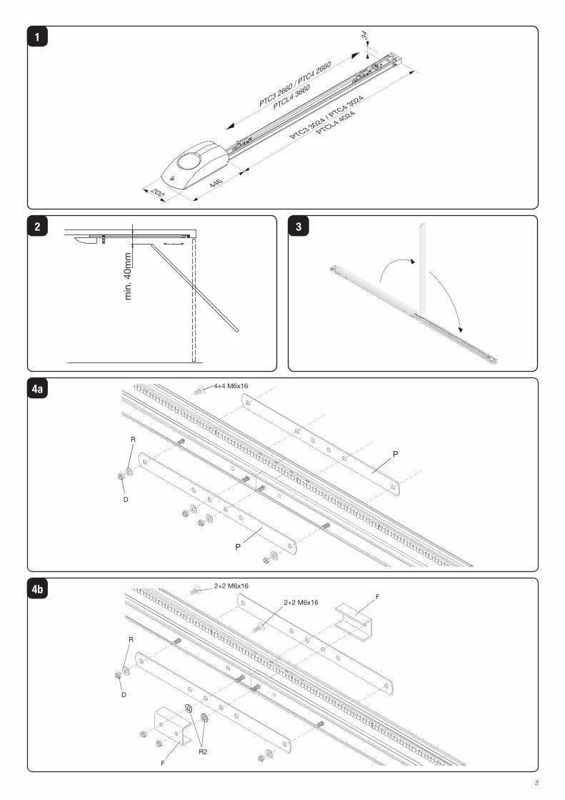
orizzontalmente sul suo bordo superiore (fig.2);- le manovre manuali devono risultare dolci e regolari.Il motoriduttore è disponibile in due versioni: JM.3 ESA (600Nm) e JM.4 ESA (1200Nm) a cui possono essere abbinate le seguenti rotaie (fig.1):PTC.3: Rotaia preassemblata con cinghia da 8mm per por-te con altezza massima di 2,5m utilizzabile solo con JM.3 ESAPTC.4: Rotaia preassemblata con cinghia da 10mm per porte con altezza massima di 2,5m utilizzabile con JM.3 ESA e JM.4 ESAPTC.L4: Rotaia preassemblata con cinghia da 10mm per porte con altezza massima di 3,5m utilizzabile con JM.3 ESA e JM.4 ESA
Dati tecnici JM.3 ESA JM.4 ESA
Alimentazione
Alimentazione motore
Potenza assorbita
Velocità di trazione
Forza trazione/spinta
Grado di protezione
Intermittenza lavoro
Temp. funzionamento
Rumorosità
Altezza max. porta:
con PTC3/PTC4
con PTCL4
Peso gruppo motore
Peso totale:
con PTC3/PTC4
con PTCL4
230Vac
24Vdc
150W
8,9 m/min
600N
IP40
uso intensivo
-20°C/+70°C
<70dB (A)
2,5m
3,5m
6,2 kg
11,8kg
13,6kg
230Vac
24Vdc
315W
8,9 m/min
1200N
IP40
uso intensivo
-20°C/+70°C
<70dB (A)
2,5m
3,5m
7,6 kg
13kg
15kg
2. Installazionea) posare la rotaia su una superficie piana e distenderla come
indicato in Fig.3b) facendo riferimento a Fig. 4, allineare le due estremità
delle rotaie e fissarle con i due piatti P utilizzando le 8 viti M6X16, i dadi D e le rondelle R.
Nel caso di utilizzo della rotaia PTC4/PTCL.4 occorre fissare anche le staffe F evidenziate in Fig.4b, facendo attenzione alla posizione delle rondelle R2 che devono essere interposte tra staffa F e piatto P.
c) verificare il tensionamento della cinghia, se necessario può essere regolata a mezzo del dado D evidenziato in Fig.5.
La cinghia correttamente tensionata mantiene la posizione lungo tutto il binario, senza flessioni, risultando in ogni caso cedevole ad una leggera pressione manuale.
d) muovere il carrello di trascinamento (Fig.6) fino a far col-limare la sede della puleggia (rif. S di Fig. 7) con il perno dell'albero motore (rif. P di Fig. 7)
e) fissare il binario alla base del motoriduttore come da Fig.7. Fissare con le 5 viti D4,8x38 la rotaia alla base del motoriduttore.
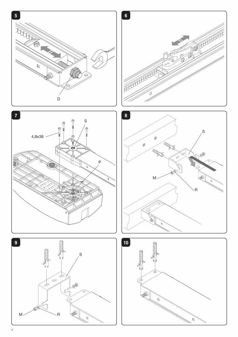
f) fissare la staffa di aggancio S al muro (Fig.8) o al soffitto (Fig.9), tracciando in corrispondenza al centro della porta i due punti di fissaggio. Agganciare la rotaia alla staffa e fissarla con i dadi M e le rondelle R. Posare il corpo motoriduttore a terra.
Se gli spazi non consentono l'uso della staffa S, è possibile fissare il binario direttamente al soffitto utilizzando i fori evidenziati in Fig.10.
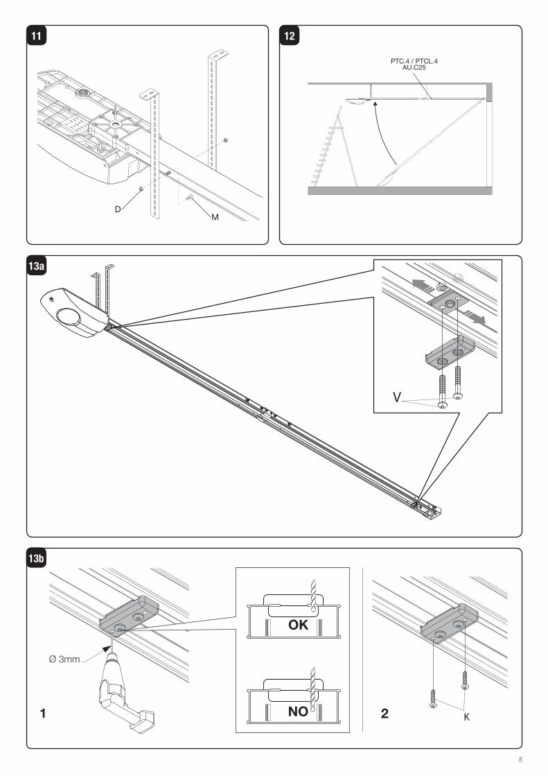
g) predisporre le staffe di attacco al soffitto utilizzando le apposite sedi nella rotaia in prossimità del motoriduttore (Fig.11) e fissandole con le viti M i dadi D. Nelle rotaie PTC.4 e PTC.L4 sono fornite altre due staffe di attacco al soffitto da fissare in prossimità della giunzione tra i binari.
h) utilizzando una scala alzare il motoriduttore (Fig.12), se-gnare i punti di fissaggio delle staffe, forare e fissare il motoriduttore utilizzando viti e tasselli adatti al materiale.
i) fissare provvisoriamente i fermi meccanici di apertura e chiusura, a inizio e fine binario, utilizzando le viti K come evidenziato in Fig.13a. Al termine della fase di messa a punto dell'automazione, i fermi verranno posizionati con maggior precisione e fissati definitivamente al binario per mezzo delle 2 viti X, effettuando due fori come indicato in Fig. 13b.
Nota: prestare attenzione a non trapassare i due fermi nell'effettuare i fori.
l) collegare l’asta di trascinamento A al pattino di trascina-mento mediante la vite a testa cilindrica M6x20 e il dado autobloccante, evitando di bloccare l’asta stessa. Fissare la staffa S alla porta in modo che, a porta chiusa, l’asta A sia in posizione pressoché verticale. Se necessario accorciare l'asta di trascinamento A.
Nel caso di ante pesanti si consiglia di utilizzare sia i fori superiori sia quelli frontali.
m) infilare il cordino nella leva di blocco e nel pomello e an-nodare come indicato nel particolare di Fig.14
n) applicare alla porta l'adesivo di avvertenza fornito in dota-zione:
3. Memorizzazione delle posizioni di apertura e chiusuraIl motoriduttore dispone di una centrale di comando con funzione di memorizzazione delle posizioni di apertura e chiusura. La procedura di memorizzazione è descritta nelle istruzioni fornite con la centrale e richiede il posizionamento dei fermi meccanici di Fig.13.
11
4. Regolazione della velocitàLa regolazione della velocità della porta è gestita dalla cen-trale di comando. Fate riferimento alle specifiche istruzioni.
ATTENZIONE!: La regolazione della velocità della porta influisce sul grado di sicurezza dell'automazione.Rispettare le normative vigenti.
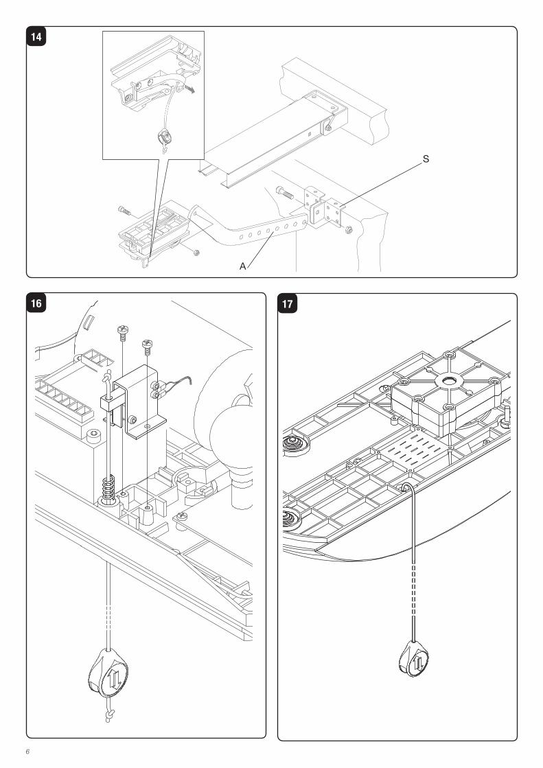
5. Accessori (opzionali)Kit batterie di emergenza JM.CB: consente il funzionamento dell'automazione in assenza di alimentazione di rete.Il kit è composto da: scheda caricabatterie, 2 batterie 12V, staffa di fissaggio, viti e cablaggiLe batterie vanno installate sulla parte superiore della base del motoriduttore come da Fig.16.Per il collegamento delle batterie fate riferimento alle speci-fiche istruzioni.Nota: Una volta installate le batterie sporgono di circa 10mm dal profilo superiore della rotaia.
Comando manuale a filo JM.PP: consente il comando dell'automazione dall'interno della rimessa con comando a filo evitando l'installazione di pulsan-tiere. Il kit è composto da: gruppo microinterruttore, comando a filo con pomello, molla e cablaggi (Fig.16)Per l'installazione fate riferimento alle specifiche istruzioni.La Fig.17 raffigura il cordino in posizione di lavoro.
6. Manovra manuale dall’esternoNelle porte sezionali è possibile sbloccare l’automazione anche dall’esterno utilizzando l’art. JM.SF (Fig.18).a) infilare il cavo i metallo nel pattino di scorrimento come
indicato nel particolare di Fig.18.b) avvitare il registro sulla staffa e infilare la guaina .c) fissare l’altro capo del cavo al dispositivo di sblocco uti-
lizzato. Nella figura è rappresentato a titolo di esempio il collegamento alla maniglia per porte da garage AU.MS .
NOTA: E’ utilizzabile qualsiasi dispositivo di sblocco a filo purché disponga di una corsa di almeno 15mm.Se il dispositivo è in grado di mantenere la leva in posizione di sblocco (es. AU.MS) risulta più pratico tagliare la levetta di aggancio evidenziata nel particolare di Fig. 18. In questo modo riportando la maniglia nelle posizione originale si ripri-stina il funzionamento automatico.
7. Montaggio su porte basculantiBasculante a contrappesi (Fig.19): le basculanti a contrappesi necessitano dell’apposito braccio art. AU.C25. Unici accorgimenti per il montaggio di quest’ultimo sono:• fissare il braccio sul filo superiore della porta• mettere a piombo il braccio stesso.
ATTENZIONELa polizza RC prodotti, che risponde di eventuali danni a cose o persone causati da difetti di fabbricazione, richiede l’utilizzo di accessori originali Benincà.
12
EC Declaration of Conformity Directive 2004/108/EC(EMC); 2006/95/EC (LVD)
Manufacturer: Automatismi Benincà SpA.Address: Via Capitello, 45 - 36066 Sandrigo (VI) – Italy It is hereby stated that the product pulling automatic system for sectional doors model JM.3 ESA/JM.4 ESA.is compliant with provisions set forth in the following EC Directives:- DIRECTIVE 2004/108/EC OF THE EUROPEAN PARLIAMENT AND OF THE COUNCIL of 15 December 2004, on the harmonisa-tion of the laws of Member States relating to electromagnetic compatibility and which cancels Directive 89/336/EEC, according to the following harmonised regulations: EN 61000-6-2:2005, EN 61000-6-3:2007.- DIRECTIVE 2006/95/EC OF THE EUROPEAN PARLIAMENT AND OF THE COUNCIL of 12 December 2006, on the harmonisation of the laws of Member States relating to electrical equipment designed for use with certain voltage limits, according to the following harmonised regulations: EN 60335-1:2002 + A1:2004 + A11:2004 + A12:2006 + A2:2006 + A13:2008; EN 60335-2-103:2003.- DIRECTIVE 2006/42/EC OF THE EUROPEAN PARLIAMENT AND OF THE COUNCIL of 17 May 2006, on machinery, which amends Directive 95/16/EC, and complies with the requisites for the “partly completed machinery (almost machinery)” set forth in the EN13241-1:2003 regulation.• Moreover, Automatismi Benincà SpA declares that the pertaining technical documentation has been drawn up in compliance with Attach-ment VII B of the 2006/42/ EC Directive and that the following requirements have been complied with: 1.1.1 - 1.1.2 - 1.1.3 - 1.1.5 - 1.2.1 - 1.2.3 - 1.2.6 - 1.3.1 - 1.3.2 - 1.3.3 - 1.3.4 - 1.3.7 - 1.3.9 - 1.5.1 - 1.5.2 - 1.5.4 - 1.5.5 - 1.5.6 - 1.5.7 - 1.5.8 - 1.5.10 - 1.5.11 - 1.5.13 - 1.6.1 - 1.6.2 - 1.6.4 - 1.7.2 - 1.7.4 - 1.7.4.1 - 1.7.4.2 - 1.7.4.3.• The manufacturer undertakes that information on the “partly completed machinery” will be sent to domestic authorities. Transmission ways are also included in the undertaking, and the Manufacturer’s intellectual property rights of the “almost machinery” are respected.• It is highlighted that commissioning of the “partly completed machinery” shall not be provided until the final machinery, in which it should be incorporated, is declared compliant, if applicable, with provisions set forth in the Directive 2006/42/EC on Machinery.• Moreover, the product, as applicable, is compliant with the following regulations: EN 12445:2002, EN 12453:2002, EN 12978:2003.
Benincà Luigi, Legal Officer.Sandrigo, 22 November 2010.
The product shall not be used for purposes or in ways other than those for which the product is intended for and as described in this manual. Incorrect uses can damage the product and cause injuries and damages.
The company shall not be deemed responsible for the non-compliance with a good manufacture technique of gates as well as for any deformation, which might occur during use.
Keep this manual for further use.
Qualified personnel, in compliance with regulations in force, shall install the system.
Packaging must be kept out of reach of children, as it can be hazardous. For disposal, packaging must be divided the various types of waste (e.g. carton board, polystyrene) in compliance with regulations in force.
The installer must supply all information on the automatic, manual and emergency operation of the automatic system and supply the end user with instructions for use.
WARNING
•An omnipolar switch/section switch with remote contact opening equal to, or higher than 3mm must be provided on the power supply mains..
Make sure that before wiring an adequate differential switch and an overcurrent protection is provided.
Pursuant to safety regulations in force, some types of in-stallation require that the gate connection be earthed.
During installation, maintenance and repair, cut off power supply before accessing to live parts.
Descriptions and figures in this manual are not binding. While leaving the essential characteristics of the product unchanged, the manufacturer reserves the right to modify the same under the technical, design or commercial point of view without necessarily update this manual.
13
IntroductionThank you for choosing our JM.3 ESA/JM.4 ESA ratiomo-tor.All items in the wide Benincà production range are the result of twenty-years’ experience in the automatism sector and of continuous research for new materials and advanced technologies.We are, therefore, in the position to offer highly reliable products that due to their power, effectiveness and useful life, fully satisfy the final user’s requirements.All our products are covered by warranty.Possible injury to people or accidents caused by defects in construction are covered by a civil liability policy drawn up with one of the major insurance companies.
1. General informationThe system has been studied to motorize sectional doors.To be applied onto balancing doors, a special fitting arm is required (item AU.C25).In any case, following conditions will have to be observed:- the distance between the door highest point and the ceiling
must be at least 40mm (fig. 2).- it has to be possible to open and close the door by pulling
and pushing horizontally its top edge (fig.2).- manual moves must be smooth and regular.The gear motor is available in two versions: JM.3 ESA (600Nm) and JM.4 ESA (1200Nm) to which the following tracks can be matched (fig.1):PTC.3: Pre-assembled track, with 8 mm belt, 2.5m max height, for JM.3 ESA only PTC.4: Pre-assembled track, with 10 mm belt, for doors with 2.5 m max height, for JM.3 ESA and JM.4 ESAPTC.L4: Pre-assembled track, with 10mm belt, for doors with 3.5 m max height, for JM.3 ESA and JM.4 ESA
Technical data JM.3 ESA JM.4 ESA
Feed
Motor feed
Absorbed rating
Drive speed
Drive/thrust force
Degree of protection
Jogging
Operating temp.
Noise level
Max. door height:
with PTC3/PTC4
with PTCL4
Power unit weight
Total weight:
with PTC3/PTC4
with PTCL4
230Vac
24Vdc
150W
8,9 m/min
600N
IP40
Intensive Use
-20°C/+70°C
<70dB (A)
2,5m
3,5m
6,2 kg
11,8kg
13,6kg
230Vac
24Vdc
315W
8,9 m/min
1200N
IP40
Intensive USe
-20°C/+70°C
<70dB (A)
2,5m
3,5m
7,6 kg
13kg
15kg
2. Installation a) Place the track on a flat surface and lay it as shown in
Fig.3b) Referring to Fig. 4, align both ends of the tracks and fit
them with the two plates P, by using the eight M6X16 screws, the nuts D and the washers R.
c) Make sure that the belt is correctly tensioned. If necessary, it can be adjusted through nut D, as shown in Fig.5.
The correctly tensioned belt keeps its position along the entire track, without bending, but still resilient at a slight
pressure by hand.d) Move the drive carrier (Fig.6) until the pulley housing (ref.
S of Fig. 7) touches the motor shaft pin (ref. P of Fig. 7)e) Fix the track to the basis of the gear motor, as per Fig.7.
Fit the track to the basis of the gear motor, with the five D4,8x38 screws.
f) Fit the hooking bracket S to wall (Fig.8) or ceiling (Fig.9). Mark the two fitting points corresponding to the centre of the door. Hook the track to the bracket and fix it by means of nuts M and washers R. Rest the gear motor body on the floor.
If there is not enough space to use the bracket S, the track can be fixed directly to the ceiling through the holes shown in Fig.10.
g) Position the fitting brackets to ceiling by means of the special housings in the track, near the gear motor (Fig.11) and fix them by means of screws M and nuts D. Two fitting brackets for mounting to ceiling are supplied with PTC.4 and PTC.L4 tracks. They must be fitted near the joining point of the tracks.
h) By using a ladder, hoist the gear motor (Fig.12), mark the fitting points of the brackets, drill the holes and fix the gear motor by means of screws and screw anchors suited to the material.
i) temporarily fix the opening and closing mechanical stop-pers, at beginning and end of track, by using the screws K, as highlighted in Fig.13a. At the end of the adjustment phase of the automatic system, the stoppers will be posi-tioned more precisely and firmly fixed to the track between the 2 screws X, while drilling two holes, as indicated in Fig. 13b.
Note: while making the holes, take care not to drill the stoppers as well.
l) Connect the driving rod A to the drive slide by means of the M6x20 cylinder head screws and the self-tapping nut. The rod movement should not be obstructed. Fix the bracket S to the door so that, with closed door, the rod A is in an almost vertical position. Shorten the drive rod A, if required.
In the event of heavy doors, it is recommended to use both upper and front holes.
m) Insert the cord in the release lever and in the knob. Make a knot as indicated in the detail of Fig.14.
n) Apply the warning sticker supplied to the door:
3. How to store the opening and closing positions in memory
The gear motor is equipped with a control unit with a memo-risation function of the opening and closing positions. The memorisation procedure is described in instructions supplied with the control unit and requires the positioning of the me-chanical stoppers, cf. Fig.13.
4. Speed adjustmentThe door speed is controlled by the control unit. Please refer to special instructions.
WARNING!: The adjustment of the door movement speed affects the safety level of the automatic system.Comply with regulations in force.
14
5. Accessories (optional)JM.CB Emergency Battery Kit: It permits the operation of the automatic system in the event of power failure.The kit is composed of: battery charge card, 2 batteries at 12V, fitting bracket, screws and cables.The batteries must be installed on the upper part of the gear motor basis, as per Fig.16.To connect batteries, please refer to specific instructions.Note: Once installed, the batteries protrude from the track upper profile by approx. 10mm.
JM.PP Cord Manual Control: It permits the control of the automatic system from indoor by means of a cord, thus avoiding the installation of a keyboard. The kit is composed of: micro-switch group, cord control with knob, spring and cables (Fig.16)For the installation, please refer to specific instructions.Fig.17 shows the cord in working position.
6. Manual operation from outdoorIn sectional doors, the system can be released also from outdoor by using item JM.SF (Fig.18).A. Insert the metal cable in the slide, as indicated in Figure
18.B. Fit the adjuster on the bracket and insert the sheath.C. Fix the other end of the cable to the release device. The
figure shows an example of connection to the garage door handle AU.MS.
N.B.: Any type of cord release device can be used under the condition that the release stroke is of at least 15 mm.If the device is able to keep the lever in the release position (e.g. AU.MS) it would be easier to cut the hooking lever, as shown in the detail of Fig. 18. In this way, by moving the handle in the original position, the automatic operation is reset.
7. Assembling onto balancing doorsOverhead door with balanceweights (fig.19): these doors
need the special arm art. AU.C25. In order to assemble it make sure that:• the arm is fixed to the top edge of the door.• the arm is levelled.
CAUTIONThe civil liability policy, which covers possible injuries to peo-ple or accidents caused by defects in construction, requires to use original Benincà accessories.

15
EG-KonformitätserklärungErklärung gemäß Richtlinie 2004/108/CE(EMV); 2006/95/CE(LVD)
Hersteller: Automatismi Benincà SpAAdresse: Via Capitello, 45 - 36066 Sandrigo (VI) - ItalienErklärt, dass das Produkt: Automatische Schleppvorrichtung für sektionale Türen:JM.3 ESA/JM.4 ESA.folgenden EG-Richtlinien entspricht:• RICHTLINIE 2004/108/EG DES EUROPÄISCHEN PARLAMENTS UND DES RATES vom 15. Dezember 2004 zur Angleichung der Rechtsvorschriften der Mitgliedstaaten über die elektromagnetische Verträglichkeit und zur Aufhebung der Richtlinie 89/336/EWG, gemäß nachstehenden Normen: EN 61000-6-2:2005, EN 61000-6-3:2007.• RICHTLINIE 2006/95/EG DES EUROPÄISCHEN PARLAMENTS UND DES RATES vom 12. Dezember 2006 zur Angleichung der Rechtsvorschriften der Mitgliedstaaten betreffend elektrische Betriebsmittel zur Verwendung innerhalb bestimmter Spannungsgrenzen, gemäß nachstehenden Normen: EN 60335-1:2002 + A1:2004 + A11:2004 + A12:2006 + A2:2006 + A13:2008; EN 60335-2-103:2003.• RICHTLINIE 2006/42/EG DES EUROPÄISCHEN PARLAMENTS UND DES RATES vom 17. Mai 2006 über Maschinen, zur Auf-hebung der Richtlinie 95/16/EG, gemäß Anforderungen für „unvollständige Maschinen“ und nachstehender Norm: EN13241-1:2003.• Automatismi Benincà SpA erklärt, dass die technischen Unterlagen gemäß Anhang VII Teil B der Richtlinie 2006/42/EG erstellt wurden und dass das Produkt folgenden Anforderungen entspricht: 1.1.1 - 1.1.2 - 1.1.3 - 1.1.5 - 1.2.1 - 1.2.3 - 1.2.6 - 1.3.1 - 1.3.2 - 1.3.3 - 1.3.4 - 1.3.7 - 1.3.9 - 1.5.1 - 1.5.2 - 1.5.4 - 1.5.5 - 1.5.6 - 1.5.7 - 1.5.8 - 1.5.10 - 1.5.11 - 1.5.13 - 1.6.1 - 1.6.2 - 1.6.4 - 1.7.2 - 1.7.4 - 1.7.4.1 - 1.7.4.2 - 1.7.4.3.• Der Hersteller verpflichtet sich die Informationen zu der „unvollständigen Maschine“ einzelstaatlichen Stellen auf begründetes Verlangen zu übermitteln. Durch die Übermittlung bleibt das intellektuelle Eigentum des Herstellers der „unvollständigen Maschine“ unberührt.• Diese „unvollständige Maschine“ darf erst dann in Betrieb genommen werden, wenn gegebenenfalls festgestellt wurde, dass die Maschine, in die die unvollständige Maschine eingebaut werden soll, den Bestimmungen der Maschinenrichtlinie 2006/42/EG entspricht.• Das Produkt entspricht außerdem, falls zutreffend, folgenden Normen:EN 12445:2002, EN 12453:2002, EN 12978:2003.
Benincà Luigi, RechtsvertreterSandrigo, 02/11/2010.
Das Produkt darf nicht für andere Zwecke oder auf andere Weise verwendet werden, als in der vorliegenden Anlei-tung beschrieben. Ein ungeeigneter Gebrauch kann das Produkt beschädigen und eine Gefahr für Personen und Sachen darstellen.
Wir übernehmen keinerlei Haftung für Schäden, die sich aus einer unsachgerechten Montage der Tore und aus daraus folgenden Verformungen ergeben können.
Bewahren Sie dieses Handbuch für Nachschlagzwecke auf.
Die Installation darf nur von qualifizierten Fachleuten laut den geltenden Vorschriften vorgenommen werden.
Das Verpackungsmaterial fern von Kindern halten, da es eine potentielle Gefahr darstellt. Das Verpackungsmaterial nicht ins Freie werfen, sondern je nach Sorte (z.B. Pappe, Polystyrol) und laut den örtlich geltenden Vorschriften entsorgen.
Der Installateur hat dem Benutzer alle Informationen über den automatischen, manuellen Betrieb sowie den Not-Betrieb der Automatik zusammen mit der Bedienungsan-leitung zu liefern.
HINWEISE
•Das Stromnetz muss mit einem allpoligen Schalter bzw. Trennschalter ausgestattet sein, dessen Kon-takte einen Öffnungsabstand gleich oder größer
als 3 aufweisen. Kontrollieren, ob der elektrischen Anlage ein geeigneter Differentialschalter und ein Überspannung-sschutzschalter vorgeschaltet sind.
Einige Installationstypologien verlangen den Anschluss des Flügels an eine Erdungsanlage laut den geltenden Sicherheitsnormen.
Während der Installation, der Wartung und der Reparatur, die Anlage stromlos machen bevor an den elektrischen Teilen gearbeitet wird.
Die in diesem Handbuch enthaltenen Beschreibungen und Abbildungen sind nicht verbindlich. Ausgenommen der Haupteigenschaften des Produkts, behält sich der Hersteller das Recht vor eventuelle technische, konstru-ktive oder kommerzielle Änderungen vorzunehmen ohne dass er vorliegende Veröffentlichung auf den letzten Stand bringen muss.
16
c) Die Riemenspannung prüfen und falls erforderlicht mit Hilfe der Mutter D (in Abb. 5) einstellen.
Wenn der Riemen richtig gespannt ist, ist er entlang der gesamten Schiene stabil; er verläuft gerade, ohne Biegung und lässt sich von Hand leicht eindrücken.
d) Den Zugschlitten bewegen (Abb. 6) bis der Sitz der Scheibe (Ref. S in Abb. 7) an den Stift der Motorwelle (Ref. P in Abb. 7) anschlägt
e) Die Schiene am Boden des Antriebs wie in Abb. 7 befesti-gen. Mit den 5 Schrauben D4,8x38 die Schiene am Boden des Antriebs befestigen.
f) Den Einhängebügel S an die Wand (Abb. 8) oder an die Decke (Abb. 9) befestigen und dazu die zwei Befestigungs-stellen mittig zum Tor markieren. Die Schiene einhängen und mit den Muttern M und den Unterlegscheiben R be-festigen. Den Körper des Antriebs auf den Boden legen.
Falls wegen Platzmangel der Bügel S nicht eingesetzt werden kann, kann die Schiene direkt an die Decke und die in Abb. 10 abgebildeten Löcher befestigt werden.
g) Die Bügel zur Befestigung an die Decke durch die Sitze in der Schiene in der Nähe des Antriebs (Abb. 11) einsetzen und mit den Schrauben M und den Muttern D befestigen. Die Schienen PTC.4 und TC.L4 sind mit weiteren zwei Bügeln versehen, die in der Nähe der Schienenverbin-dungsstellen befestigt werden.
h) Mit Hilfe einer Leiter den Antrieb (Abb. 12) heben und die Befestigungsstellen der Bügel markieren, bohren und den Antrieb mit geeigneten Schrauben und Dübeln befesti-gen.
i) die mechanischen Anschläge zum Öffnen und Schlie-ßen am Anfang und am Ende der Schienen wie in Abb. 13a gezeigt, mit den Schrauben K befestigen. Nach der Feineinstellung der Automatik, die Endanschläge genau-er positioneren und endgültig an die Schiene mit den 2 Schrauben X befestigen. Dazu müssen 2 Löcher, wie in Abb. 13b gezeigt, gebohrt werden.
Bemerkung: Beim Bohren darauf achten, dass die beiden Endan-schläge nicht durchbohrt werden.
l) Den Zugstab A an den Gleitschuh mit der Zylinderkopf-schraube M6x20 und der selbstsichernden Mutter befes-tigen ohne den Stab jedoch zu blockieren. Den Bügel S an das Tor so befestigen, dass bei geschlossenem Tor der Stab A praktisch senkrecht zu stehen kommt. Falls erforderlich, den Zugstab A kürzen.
Bei schweren Toren empfehlen wir sowohl die oberen als auch die frontalen Löcher zu verwenden.
m) Die Schnur durch den Sperrhebel und den Kugelgriff ziehen und wie in Abb. 14 gezeigt, binden.
n) Das mitgelieferte Etikett mit dem Warnhinweis auf das Tor kleben:
3. Speichern der Öffnungs- und SchließpositionenDer Antrieb ist mit einer Steuerungseinheit ausgestattet die die Öffnungs- und die Schließposition speichern kann. Die Speicherungsprozedur ist in der Anleitung beschrieben, die mit der Einheit geliefert wird; gleichzeitig müssen die mecha-nischen Anschläge positioniert werden (siehe Abb. 13).
4. Geschwindigkeit einstellenDie Einstellung der Torgeschwindigkeit wird von der Steu-
EinleitungWir danken Ihnen dafür, daß Sie sich für das JM.3 ESA/JM.4 ESA Steuergehäuse entschieden haben.Alle Produkte der umfangreichen Benincà Produktion sind das Ergebnis der zwanzigjährigen Erfahrungen im Bereich der Automation und der ständigen Erforschung von neuen Materialien und fortgeschrittenen Technologien.Aus diesem Grund sind wir heute in der Lage, zuverlässige Produkte anzubieten, die, dank ihren Stärke, Wirksamkeit und Haltbarkeit, der Anforderungen des Endverbrauchers völlig gerecht werden.Alle Produkte sind durch Garantie gedeckt.Eventuelle Personen- oder Sachschäden, die durch Ferti-gungsfehler verursacht werden können, werden durch eine der wichtigsten Versicherungsgesellschaften gedeckt.
1. Allgemeine InformationDie Automatik bedient über einen Motor sektionale Türen; um an Schwenktüren installiert zu werden, muss ein spezieller Arm angeschlossen werden (art. AU.C25).Jedenfalls müssen folgende Bedingungen erfüllt werden:- Der Abstand zwischen der höchsten Stelle des Tores und
der Decke muß wenigstens 40mm sein (Abb. 2).- das Tor muß zu öffnen und zu schließen sein, indem man
es an seinem Oberrand zieht und schiebt (Abb. 2).- Die Handgriffe müssen sanft und regelmäßig sein.Der Antrieb ist in zwei Ausführungen erhältlich: JM.3 ESA (600Nm) und JM.4 ESA (1200Nm) die mit folgen-den Schienen kombiniert werden können (Abb. 1): PTC 3: vormontierte Schiene mit Riemen zu 8mm für Tore mit einer maximalen Höhe von 2,5m, nur mit JM.3 ESA verwendbarPTC 4: vormontierte Schiene mit Riemen zu 10 mm für Tore mit einer maximalen Höhe von 2,5m, mit JM.3 ESA und JM.4 ESA verwendbarPTC.L4: vormontierte Schiene mit Riemen zu 10mm für Tore mit einer maximalen Höhe von 3,5m, mit JM.3 ESA und JM.4 ESA verwendbar
Technische Daten JM.3 ESA JM.4 ESA
Speisung
Motorspeisung
Leistung
Zuggeschwindigkeit
Zugkraft/Schubkraft
Schutzart
Betriebsintervall
Betriebstemperatur
Geräuschentwicklung
Max. Torhöhe:
mit PTC3/PTC4
mit PTCL4
Gewicht der Motoreinheit
Gesamtgewicht:
mit PTC3/PTC4
mit PTCL4
230Vac
24Vdc
150W
8,9 m/min
600N
IP40
Intensive Nutzung
-20°C/+70°C
<70dB (A)
2,5m
3,5m
6,2 kg
11,8kg
13,6kg
230Vac
24Vdc
315W
8,9 m/min
1200N
IP40
Intensive Nutzung
-20°C/+70°C
<70dB (A)
2,5m
3,5m
7,6 kg
13kg
15kg
2. Installationa) Die Schiene auf eine ebene Fläche wie in Abb. 3 gezeigt,
legenb) Die beiden Schienenenden aufreihen (siehe Abb. 4) und mit
den beiden Scheiben P mit Hilfe von 8 Schrauben M6x16, Muttern D und Unterlegscheiben R befestigen.
17
ereinheit gesteuert. Beziehen Sie sich bitte auf die entspre-chenden Anweisungen.
ACHTUNG! Die Einstellung der Torgeschwindigkeit hat Einfluss auf die Sicherheit der Automatik.Die geltenden Vorschriften beachten!
5. Zubehör (Option)Set Notfallbatterie JM.CB: Ermöglicht den Betrieb der Automatik bei Stromausfall.Das Set besteht aus: Batterieladekarte, 2 Batterien 12V, Befestigungsbügel, Schrauben und Verkabelung.Die Batterien werden am oberen Teil des Antriebs montiert, wie die Abb. 16 zeigt.Für den Anschluss der Batterien beziehen Sie sich bitte auf die entsprechenden Anweisungen. Bemerkung: Wenn die Batterien installiert sind, ragen sie circa 10 mm aus dem oberen Schienenprofil heraus.
Manuelle Drahtsteuerung JM.PP: ermöglicht es die Automatik von innen durch eine Drahtsteu-erung zu steuern ohne eine Tastatur installieren zu müssen. Das Set besteht aus: Mikroschaltereinheit, Drahtsteuerung mit Kugelgriff, Feder und Verkabelung (Abb. 16)Zur Installation beziehen Sie sich bitte auf die entsprechen-den Anweisungen.Die Abbildung 17 zeigt die Schnur in Arbeitsposition.
6. Manuelle Betätigung von außenBei den sektionalen Toren kann die Automatik auch von außen durch den Einsatz des Art. JM.SF (Abb.18) entsichert werden.A Das Metallkabel in den Gleitschuh, wie in Abb. 18 gezeigt,
stecken. B Die Stellschraube am Bügel festschrauben und die Hüslse
einsetzen. C Das andere Kabelende an die verwendete Vorrichtung befes-
tigen. Die Abbildung zeigt als Beispiel den Anschluss an den Türgriff einer Garage AU.MS .
BEMERKUNG: Es kann eine beliebige Entsicherungsvor-richtung mit Draht verwendet werden, vorausgesetzt sie hat einen Hub von mindestens 15 mm. Wenn die Vorrichtung den Hebel in der Entsicherungsposition hält (Bsp. AU.MS) könnte es sinnvoller sein den Einhän-gehebel zu schneiden, wie die Abb. 18 zeigt. So kann der Handgriff in die Ausgangsposition zurückgebracht und der automatische Betrieb wieder hergestellt werden.
7. Montage an SchwenktürenKipptor mit Gegengewichten (Bild 19): Kipptore mit Gegen-gewichten erfordern den Sonderarm Teil. AU.C25.Bei seiner Anbringung ist nur zu beachten:• Arm an der oberen Kante des Tores befestigen,• Arm lotrecht stellen.
BITTE BEACHTENDie Versicherung deckt nur Personen- oder Sachschäden, die durch Fertigungsfehler verursacht werden und gilt nur bei Einsatz von Benincà Original-Ersatzteilen.
18
Déclaration CE de conformitéDéclaration conforme aux Directives 2004/108/CE(EMC); 2006/95/CE(LVD)
Fabricant: Automatismi Benincà SpAAdresse: Via Capitello, 45 - 36066 Sandrigo (VI) - ItalieDéclare que le produit: Automatisme à entraînement pour portes sectionnelles:JM.3 ESA/JM.4 ESA.est conforme aux conditions requises par les Directives CE suivantes:• DIRECTIVE 2004/108/CE DU PARLEMENT EUROPÉEN ET DU CONSEIL du 15 décembre 2004 concernant le rapprochement des législations des États membres relatives à la compatibilité électromagnétique et qui abroge la Directive 89/336/CEE, selon les suivantes normes harmonisées: EN 61000-6-2:2005, EN 61000-6-3:2007.• DIRECTIVE 2006/95/CE DU PARLEMENT EUROPÉEN ET DU CONSEIL du 12 décembre 2006 concernant le rapprochement des législations des États membres relatives au matériel électrique destiné à être employé dans certaines limites de tension ,selon les suivantes normes harmonisées: EN 60335-1:2002 + A1:2004 + A11:2004 + A12:2006 + A2:2006 + A13:2008; EN 60335-2-103:2003.• DIRECTIVE 2006/42/CE DU PARLEMENT EUROPÉEN ET DU CONSEIL du 17 mai 2006 concernant les machines et qui modifie la Directive 95/16/CE, en respectant les conditions requises pour les “quasi-machines”, selon la norme suivante: EN13241-1:2003.• Automatismi Benincà SpA déclare, en outre, que la documentation technique pertinente a été constituée conformément à l’annexe VII B de la Directive 2006/42/CE et que les conditions requises essentielles ci de suite ont été respectées: 1.1.1 - 1.1.2 - 1.1.3 - 1.1.5 - 1.2.1 - 1.2.3 - 1.2.6 - 1.3.1 - 1.3.2 - 1.3.3 - 1.3.4 - 1.3.7 - 1.3.9 - 1.5.1 - 1.5.2 - 1.5.4 - 1.5.5 - 1.5.6 - 1.5.7 - 1.5.8 - 1.5.10 - 1.5.11 - 1.5.13 - 1.6.1 - 1.6.2 - 1.6.4 - 1.7.2 - 1.7.4 - 1.7.4.1 - 1.7.4.2 - 1.7.4.3.• Le fabricant s’engage à transmettre aux autorités nationales, suite à une demande motivée, les informations concernant la “quasi-machine”. Cet engagement comprend les modalités de transmission et reste sans préjudices pour les droits de propriété intellectuelle du fabricant sur la “quasi machine”.• On communique que la “quasi-machine” ne doit pas être mise en service avant que la machine finale, dans laquelle elle doit être incorporée, ait été elle même déclarée conforme, le cas échéant, aux dispositions de la Directive 2006/42/CE.• En outre le produit, exclusivement en ce qui concerne les parties applicables, résulte conforme aux normes suivantes:EN 12445:2002, EN 12453:2002, EN 12978:2003.
Benincà Luigi, Responsable Légal.Sandrigo, 02/11/2010.
Il est interdit d’utiliser ce produit pour l’utilisation du pro-duit ou avec des finalités ou modalités non prévues par le présent manuel. Toute autre utilisation pourrait compro-mettre l’intégrité du produit et présenter un danger pour les personnes ou pour les biens.
Le fabricant décline toute responsabilité en cas d’utilisation impropre ou d’inobservation de la bonne technique dans la construction des portails, ainsi que de toute déformation qui pourrait avoir lieu lors de son utilisation.
Toujours conserver la notice pour toute autre consultation future.
L’installation doit être faite uniquement par un personnel qualifié dans le respect total des normes en vigueur.
Tenir à l’écart des enfants tous les matériaux d’emballage car ils représentent une source potentielle de danger. Ne pas disperser les matériaux d’emballage dans l’environne-ment, mais trier selon les différentes typologies (i.e. carton, polystyrène) et les traiter selon les normes locales.
L’installateur doit fournir toutes les informations relatives au fonctionnement automatique, au déverrouillage d’ur-gence de l’automatisme, et livrer à l’utilisateur les modes d’emploi.
REGLES DE SECURITE’
•Prévoir sur le réseau de l’alimentation un interrupteur / sectionneur omnipolaire avec distance d’ouver-ture des contacts égale ou supérieure à 3 mm..
Vérifier la présence en amont de l’installation électrique d’un interrupteur différentiel et d’une protection de sur-courant adéquats.Certains types d’installation requièrent le branchement du vantail à une installation de mise à terre satisfaisant les normes de sécurité e vigueur.Avant toute intervention, d’installation, réparation et main-tien, couper l’alimentation avant d’accéder aux parties électriques.
Les descriptions et les illustrations présentées dans ce manuel ne sont pas contraignantes. En laissant inaltérées les caractéristiques essentielles du produit, le fabricant se réserve le droit d’apporter toute modification à caractère technique, de construction ou commerciale sans s’engager à revoir la cette publication.
19
IntroductionNous ne pouvons que féliciter d’avoir porté votre choix sur le moto-réducteur JM.3 ESA/JM.4 ESA.Vingt années d’expérience dans le secteur des automatis-mes ainsi que dans le recherche de nouveaux matériaux et technologies de pointe, nous ont permis de développer tous les nombreux articles de la gamme Benincà.Pour ces raisons, nous sommes en mesure de proposer des produits extrémement fiables et qui grâce à leurs puissan-ces, performances et longévité, répondent aux exigences des utilisateurs.Tous nos produits sont garantis.En plus, une police d’assurance responsabilité civile garantie la couverture d’éventuels sinistres à personnes ou objects causés par les défauts de fabrication.
1. Notice généralesL’automatisme est conçu pour motoriser des portes section-nelles; pour pouvoir l’appliquer sur des portes basculantes il nécessite d’un bras de fixation spécial (art. AU.C25).Dans tous les cas, les conditions suivantes devront être prises:- la distance entre le point le plus haut de la porte et le plafond devra être au minimum de 40mm (fig.2)- la porte devra pouvoir être ouverte et fermée en tirant et en poussant horizontalement sur son bord supérieur (fig.2).- les opérations manuelles doivent résulter douces et règu-lières.Le motoréducteur est disponible en deux versions: JM.3 ESA (600Nm) et JM.4 ESA (1200Nm) auxquels on peut associer les rails suivant (fig.1):PTC.3: Rail pré-assemblé avec courroie de 8mm pour portes ayant un auteur maxi de 2,5m utilisable uniquement avec JM.3 ESAPTC.4: Rail pré-assemblé avec courroie de 10mm pour portes ayant un auteur maxi de 2,5m utilisable uniquement avec JM.3 ESA et JM.4 ESAPTC.L4: Rail pré-assemblé avec courroie de 10mm pour portes ayant un auteur maxi de 3,5m utilisable uniquement avec JM.3 ESA et JM.4 ESA
Donnees technique JM.3 ESA JM.4 ESA
Alimentation
Alimentation moteur
Puissance absorbée
Vitesse de traction
Force traction/poussée
Indice de protection
Intermittence travail
Temp. fonctionnement
Bruit
Hauteur max. porte:
avec PTC3/PTC4
avec PTCL4
Poids groupe moteur
Poids totale:
avec PTC3/PTC4
avec PTCL4
230Vac
24Vdc
150W
8,9 m/min
600N
IP40
Usage Intensif
-20°C/+70°C
<70dB (A)
2,5m
3,5m
6,2 kg
11,8kg
13,6kg
230Vac
24Vdc
315W
8,9 m/min
1200N
IP40
Usage Intensif
-20°C/+70°C
<70dB (A)
2,5m
3,5m
7,6 kg
13kg
15kg
2. Installationa) placez le rail sur une surface plate et étendez-le comme
indiqué dans la Fig.3b) en se référant à la Fig. 4, alignez les deux extrémités du
rail et fixez-les avec deux plaques P en utilisant les 8 vis M6X16, les écrous D et les rondelles R.
c) vérifiez la tension de la courroie, si nécessaire elle peut être réglée moyennant l’écrou D mis en évidence dans la Fig.5.
La courroie dont la tension a été correctement ajustée garde sa position tout le long du rail, sans flexions, résultant en tout cas souple à une faible pression manuelle.
d) déplacez le chariot d’entraînement (Fig.6) jusqu’à ce que le siège de la poulie (rif. S di Fig. 7) ne joigne le pivot du vilebrequin (rif. P di Fig. 7)
e) fixez le rail à la base du motoréducteur comme dans la Fig.7. Fixez avec les 5 vis D4, 8x38 le rail à la base du motoréducteur.
f) fixez la bride d’accrochage S au mur (Fig.8) ou au plafond (Fig.9), en traçant en correspondance au centre de la porte les deux points de fixation. Accrochez le rail à la bride et fixez-le avec les écrous M et les rondelles R. Déposez le corps du motoréducteur par terre.
Si les espace empêche l’utilisation de la bride S, on peut fixer le rail directement sur le plafond en utilisant les trous mis en évidence dan la Fig.10.
g) prédisposez les brides d’accrochement au plafond en utilisant les sièges spéciaux dans le rail en proximité du motoréducteur (Fig.11) et fixez-les avec les vis M et les écrous D. Dans les rails PTC.4 et PTC.L4 deux autres brides d’accrochement au plafond sont fournies pour être fixées en proximité de la jonction entre les rails.
h) en utilisant une échelle, soulever le motoréducteur (Fig.12), marquez les points de fixation des brides, trouez et fixez le motoréducteur en utilisant les vis et les chevilles adaptées au matériel.
i) fixer provisoirement les butées mécaniques d’ouverture et de fermeture, au début et à la fin du rail, à l’aide des vis K comme mis en évidence dans la Fig.13a. A’ la fin de la phase de réglage de l’automation, les butés seront placées avec plus de précision et fixées de manière définitive au rail avec les 2 vis X, en perçant deux trous comme indiqué dans la Fig. 13b.
Note: attention à ne pas transpercer les deux butés en phase de perçage.
l) branchez la tige d’entraînement A à la glissière d’entraîne-ment avec la vis à tête cylindrique M6x20 et l’écrou auto-bloquant, en évitant de bloquer la tige même. Fixez la tige S à la porte de manière que, la porte ferme, la tige A soit en position presque verticale. Si nécessaire, raccourcissez la tige d’entraînement A.
En cas de vantaux lourds il est conseillé d’utiliser soit les trous supérieurs soit les trous sur le front.
m) enfilez la cordelette dans le levier de déblocage et dans la poignée, enfin nouez comme indiqué dans le détail de la Fig.14
n) appliquez à la porte l’autocollant d’avertissement en do-tation:
3. Mémorisation des positions d’ouverture et de fermeture
Le motoréducteur dispose d’une centrale de commande avec fonction de mémorisation des positions d’ouverture et de fermeture, La procédure de mémorisation est décrite dans les notices fournies avec la centrale et demande le
20
positionnement des blocages mécaniques de la Fig.13.
4. Calage de la vitesse Le calage de la vitesse de la porte est géré par la centrale de commande. Se référer aux notices spécifiques.
ATTENTION!: Le réglage de la vitesse de la porte pèse sur le degré de sécurité de l’automatisme.Respectez les normes en vigueur.
5. Accessoires (optionnels)Kit batteries de secours JM.CB: permet le fonctionnement de l’automatisme en cas de panne de courant.Le kit se compose de: carte charge-batteries, 2 batteries 12V, bride de fixation, vis et câblagesLes batteries doivent être installées sur la partie supérieure de la base du motoréducteur comme dans Fig.16.Pour brancher les batteries référez-vous aux instructions spécifiques.Note: Une fois installées, les batteries sortent de 10mm en-viron du profil supérieur du rail.
Commande manuelle à fil JM.PP: permet de commander l’automatisme dès l’intérieur du garage avec commande à fil en évitant ainsi l’installation de pupitres. Le kit se compose de: groupe microinterrupteur, commande à fil avec poigné, ressort et câblages (Fig.16)Pour l’installation référez-vous aux instructions spécifi-ques.La Fig.17 représente la cordelette en position de travail.
6. Manœuvre manuelle de l’extérieurDans les portes sectionnelles il est possible de débloquer l’automatisme même de l’extérieur en utilisant l’art. JM.SF (Fig.18).A Insérez le câble métallique dans le chariot entraînement
comme indiqué dans la Figure 18B Vissez la rosette sur la bride et insérez la gaine.C Fixez l’autre bout du câble au dispositif de déblocage
utilisé. La figure illustre à titre d’exemple l’assemblage à la poignée pour portes de garage AU.MS.
NOTA: On peut utiliser n’importe quel dispositif de déblocage à fil, à condition qu’il ait une course d’au moins 15mm.Si le dispositif est à même de maintenir le levier en position de déblocage (ex. AU.MS) il sera plus pratique de couper le levier d’accrochage mis en évidence dans le détail de la Fig. 18. De cette manière en ramenant la poigné dans sa position d’origine on rétablit le fonctionnement automatique.
7. Montages sur les portes basculantesPortes basculantes à contrepoids (fig.19): les portes bas-culantes à contrepoids nécessitent un bras approprié art. AU.C25. Les seuls moyens pour le montage de ce dernier sont:• fixer le bras sur l’arête supérieure de la porte;• mettre à plomb le bras même.
ATTENTIONPour que la police d’assurance R.C. réponde à d’eventuels sinistres causés à choses ou personnes, en cas de défauts de fabrication, il faut que soient utilisés des accessoires Benincà.
21
Declaración CE de conformidadDeclaración conforme a las Directivas 2004/108/CE(EMC); 2006/95/CE(LVD)
Fabricante: Automatismi Benincà SpA.Dirección: Via Capitello, 45 - 36066 Sandrigo (VI) - ItaliaDeclara que el producto:Automatización de arrastre para puertas plegables:JM.3 ESA/JM.4 ESA.es conforme a las condiciones de las siguientes Directivas CE:• DIRECTIVA 2004/108/CE DEL PARLAMENTO EUROPEO Y DEL CONSEJO del 15 de diciembre de 2004 sobre la aproximación de las legislaciones de los Estados miembros con relación a la compatibilidad electromagnética y que abroga la Directiva 89/336(CEE, según las siguientes normas armonizadas: EN 61000-6-2:2005, EN 61000-6-3:2007. • DIRECTIVA 2006/95/CE DEL PARLAMENTO EUROPEO Y DEL CONSEJO del 12 de diciembre de 2006 sobre la aproximación de las legislaciones de los Estados miembros con relación al material eléctrico destinado a ser utilizado dentro de determinados límites de tensión, según las siguientes normas armonizadas: EN 60335-1:2002 + A1:2004 + A11:2004 + A12:2006 + A2:2006 + A13:2008; EN 60335-2-103:2003.• DIRECTIVA 2006/42/CE DEL PARLAMENTO EUROPEO Y DEL CONSEJO del 17 de mayo de 2006 relativa a las máquinas y que modifica la Directiva 95/16/CE, respetando los requisitos para las “cuasi máquinas”, conforme a la norma siguiente: EN13241-1:2003. • Automatismi Benincà SpA declara así mismo que la documentación técnica pertinente ha sido redactada conforme al anexo VII B de la Directiva 2006/42/CE y que se han respetado los siguientes requisitos esenciales: 1.1.1 - 1.1.2 - 1.1.3 - 1.1.5 - 1.2.1 - 1.2.3 - 1.2.6 - 1.3.1 - 1.3.2 - 1.3.3 - 1.3.4 - 1.3.7 - 1.3.9 - 1.5.1 - 1.5.2 - 1.5.4 - 1.5.5 - 1.5.6 - 1.5.7 - 1.5.8 - 1.5.10 - 1.5.11 - 1.5.13 - 1.6.1 - 1.6.2 - 1.6.4 - 1.7.2 - 1.7.4 - 1.7.4.1 - 1.7.4.2 - 1.7.4.3.• El fabricante se compromete a transmitir a las autoridades nacionales, contestando a una solicitud motivada, la información pertinente sobre la “cuasi máquina”. El compromiso incluye las modalidades de transmisión y no afecta a los derechos de propiedad intelectual del fabricante de la “cuasi máquina”.• Se comunica que la “cuasi máquina” no se tiene que poner en servicio hasta que la máquina final, en la cual se tiene que incorporar, ha sido declarada conforme si aplicable, a las disposiciones de la Directiva 2006/42/CE.• Además, el producto, limitadamente a las partes aplicables, resulta ser conforme a las siguientes normas: EN 12445:2002, EN 12453:2002, EN 12978:2003.
Benincà Luigi, Responsable legal.Sandrigo, 02/11/2010.
Está prohibido utilizar el producto para finalidades o con modalidades no previstas en el presente manual. Usos incorrectos pueden causar daños al producto y poner en peligro personas y cosas.
Se rehúsa cualquier responsabilidad en caso de incum-plimiento de la buena técnica en la construcción de las cancelas, así como en cuanto a las deformaciones que pudieran producirse durante el uso.
Guardar este manual para futuras consultas.
La instalación debe ser efectuada por personal cualificado respetando plenamente las normas vigentes.
Los elementos del embalaje no se deben dejar al alcance de los niños ya que son potenciales fuentes de peligro. No tirar al medio ambiente los elementos del embalaje, sino que se deben separar según los varios tipos (por ej. cartón, poliestireno) y evacuarlos de conformidad con las normas locales.
El instalador debe proporcionar todas las informaciones relativas al funcionamiento automático, manual y de emergencia de la automatización y entregar al usuario del equipo las instrucciones de uso.
ADVERTENCIAS
•Prever en la red de alimentación un interruptor/cortacircuitos omnipolar con distancia de aper-tura de los contactos igual o mayor que 3 mm.
Comprobar que entre el aparato y la red eléctrica general haya un interruptor diferencial y una pro-tección contra sobrecorriente adecuados. Algunos tipos de instalación requieren que se conecte la hoja con una instalación de puesta a tierra conforme a las vigentes normas de seguridad.Durante las operaciones de instalación, mantenimiento y reparación, cortar la alimentación antes de acceder a las partes eléctricas.
Las descripciones y las ilustraciones presentadas en este manual no son vinculantes. Sin cambiar las características esenciales del producto, el fabricante se reserva el derecho de aportar cualquier modificación de carácter técnico, constructivo o comercial sin obligación de actualizar la presente publicación.
22
IntroducciónNos congratulamos con vd. por haber elegido el motorre-ductor JM.3 ESA/JM.4 ESA.Todos los artículos de la vasta gama Benincà son el fruto de una veinteañal experiencia en el sector de los automatismos y de una continua búsqueda de nuevos materiales y de tec-nología de vanguardia.Es precisamente por ello el que hoy nos encontramos en situación de ofrecer productos extremadamente fiables que, gracias a su potencia, eficacia y duración, satisfacen plenamente las exigencias del usuario final.Todos nuestros productos están garantizados.Además, una póliza R.C. productos, contratada con una compañía de seguros de primera línea, cubre eventuales daños a cosas o personas causados por defectos de fabri-cación.
1. Noticias generalesEl automatismo está diseñado para motorizar puertas ple-gables; para aplicarlo en puertas basculantes requiere un brazo especial de conexión (art. AU.C25).En cualquier caso deberán tenerse en cuenta las condiciones siguientes:- la distancia entre el punto más alto de la puerta y el techo debe ser de al menos 40mm. (fig.2);- la puerta deberá poder abrir o cerrarse tirando o empujando horizontalmente sobre el borde superior (fig.2);- las maniobras manuales deben resultar suaves y regula-res.El motorreductor está disponible en dos variantes: JM.3 ESA (600Nm) y JM.4 ESA (1200Nm) con los cuales se pueden asociar los siguientes rieles (fig.1):PTC.3: Riel premontado con correa de 8mm para puertas con altura máxima de 2,5m utilizable sólo con JM.3 ESAPTC.4: Riel premontado con correa de 10mm para puertas con altura máxima de 2,5m utilizable con JM.3 ESA y JM.4 ESAPTC.L4: Riel premontado con correa de 10mm para puertas con altura máxima de 3,5m utilizable con JM.3 ESA y JM.4 ESA
Datos técnicos JM.3 ESA JM.4 ESA
Alimentación
Alimentación del motor
Potencia absorbida
Velocidad de tracción
Fuerza tracción/empuje
Grado de protección
Intermitencia de trabajo
Temp. de funcionamiento
Ruido
Altura máx. de puerta:
con PTC3/PTC4
con PTCL4
Peso grupo motor
Peso total:
con PTC3/PTC4
con PTCL4
230Vac
24Vdc
150W
8,9 m/min
600N
IP40
Intensivo
-20°C/+70°C
<70dB (A)
2,5m
3,5m
6,2 kg
11,8kg
13,6kg
230Vac
24Vdc
315W
8,9 m/min
1200N
IP40
Intensivo
-20°C/+70°C
<70dB (A)
2,5m
3,5m
7,6 kg
13kg
15kg
2. Instalacióna) colocar el riel sobre una superficie plana y extenderlo como
indicado en la Fig.3
b) haciendo referencia a la Fig. 4, alinear las dos extremida-des de los rieles y fijarlas con los dos platos P, utilizando los 8 tornillos M6X16, las tuercas D y las arandelas R.
c) comprobar la tensión de la correa, a ser necesario se puede ajustar por medio de la tuerca D destacada en la Fig.5.
La correa correctamente tensada mantiene la posición a lo largo de todo el riel, sin flexiones, aunque en todo caso puede ceder a una ligera presión manual.
d) mover el carro de arrastre (Fig.6) hasta hacer coincidir el alojamiento de la polea (ref. S de la Fig. 7) con el perno del eje motor (ref. P de la Fig. 7)
e) fijar el riel a la base del motorreductor como mostrado en la Fig.7. Fijar con los 5 tornillos D4 8x38 el riel a la base del motorreductor.
f) fijar el soporte de enganche S a la pared (Fig.8) o al te-cho (Fig.9), trazando en correspondencia del centro de la puerta los dos puntos de fijación. Enganchar el riel al estribo y fijarlo con las tuercas M y las arandelas R. Poner el cuerpo del motorreductor en el suelo.
Si los espacios no permiten utilizar el soporte S, es posible fijar el riel directamente al techo utilizando los agujeros destacados en la Fig.10.
g) preparar los estribos de fijación al techo, utilizando los alojamientos previstos en el riel cerca del motorreductor (Fig.11) y fijándolos con los tornillos M y las tuercas D. Con los rieles PTC.4 y PTC.L4 se suministran otros dos estribos de fijación al techo, a fijar cerca de la unión entre los rieles.
h) utilizando una escalera, izar el motorreductor (Fig.12), marcar los puntos de fijación de los estribos, taladrar y fijar el motorreductor utilizando tornillos y tacos idóneos para el material perforado.
i) fijar provisionalmente los topes mecánicos de apertura y cierre, al inicio y al final del riel, utilizando los tornillos K como destacado en la Fig.13a. Al final de la fase de puesta a punto de la automatización, los topes se colocarán con más exactitud y se fijarán definitivamente al riel mediante los 2 tornillos X, realizando dos agujeros como mostrado en la Fig. 13b.
Nota: prestar atención en no traspasar los dos topes al realizar los agujeros.
l) conectar la vara de arrastre A al patín de arrastre utilizando el tornillo de cabeza cilíndrica M6x20 y la tuerca autobloquean-te, evitando que se bloquee la propia vara. Fijar el soporte S a la puerta de manera que, con la puerta cerrada, la vara A esté en posición casi vertical. A ser necesario, acortar la vara de arrastre A.
En el caso de puertas pesadas si aconseja utilizar tanto los agujeros superiores que los frontales.
m) Introducir el cordel en la palanca de bloque y en la em-puñadura y anudar como indicado en el detalle de la Fig.14
n) poner en la puerta el adhesivo de advertencia suministra-do:
3. Memorización de las posiciones de apertura y cierreEl motorreductor tiene una central de mando con función de memorización de las posiciones de apertura y cierre. El procedimiento de memorización se describe en las instruc-ciones suministradas con la central y requiere la colocación
23
de los topes mecánicos de la Fig.13.
4. Regulación de la velocidadLa regulación de la velocidad de la puerta la gestiona la cen-tral de control. Consúltense las instrucciones específicas.
¡ATENCIÓN! El ajuste de la velocidad de la puerta re-percute en el grado de seguridad de la automatización.Respétense las normas vigentes.
5. Accesorios (opcionales)Kit baterías de emergencia JM.CB: permite el funcionamiento de la automatización también faltando la alimentación de red.El kit se compone de: tarjeta cargador-baterías, 2 baterías de 12V, soporte de fijación, tornillos y cableadosLas baterías se instalan en la parte superior de la base del motorreductor como mostrado en la Fig.16.Para el conexionado de las baterías hágase referencia a las instrucciones específicas.Nota: Una vez instaladas las baterías salen aproximadamente 10mm del perfil superior del riel.
Mando manual por cable JM.PP: permite controlar la automatización desde el interior del garaje con un mando por cable, con lo cual se evita la instalación de pulsadores. El kit se compone de: grupo mi-crointerruptor, mando por cable con empuñadura, muelle y cableados (Fig.16)Para la instalación hágase referencia a las instrucciones específicas.La Fig.17 muestra el cordel en posición de trabajo.
6. Maniobra manual desde el exteriorEn las puertas seccionales es posible desbloquear la auto-matización también desde el exterior utilizando el art. JM.SF (Fig.18).A Insertar el cable de metal en el patín de deslizamiento como
indicado en la figura 18B Enroscar el registro sobre el soporte e insertar la vaina.C Fijar la otra extremidad del cable en el dispositivo de des-
bloqueo utilizado. En la figura se muestra, como ejemplo, la conexión a la manija para puertas de garaje AU.MS .
NOTA: se puede utilizar cualquier dispositivo de desblo-queo con cable siempre que disponga de una carrera por lo menos de 15mm.Si el dispositivo logra mantener la palanca en posición de desbloqueo (por ej. AU.MS) resulta más práctico cortar la palanca de enganche destacada en el detalle de la Fig. 18. De esta manera, volviendo a poner la manija en la posición original, se restablece el funcionamiento automático.
7. Montajes en puertas basculantesLas basculantes de contrapesos (fig.19) necesitan el corres-pondiente brazo art. AU.C25. Las únicas particularidades para este último montaje son:• fijar el brazo sobre la arista superior de la puerta.• aplomar bien dicho brazo.
ATENCIONLa póliza RC productos, que responde de eventuales daños a personas o cosas causados por defectos de fabricación, requiere la utilización de accesorios originales Benincà.
24
Deklaracja zgodności CEsporządzona zgodnie z dyrektywami europejskimi 2004/108/WE (EMC) i 2006/95/WE (LVD)
Producent: Automatismi Benincà SpAAdres: Via Capitello, 45 - 36066 Sandrigo (VI) - Włochyoświadcza, że produkt: jest zgodny z wymogami następujących dyrektyw WE:Automatyzm do bram sekcyjnych model:JM.3 ESA/JM.4 ESA• DYREKTYWY 2004/108/WE RADY I PARLAMENTU EUROPEJSKIEGO z dnia 15 grudnia 2004r. w sprawie zbliżania ustawodawstwa państw członkowskich w zakresie kompatybilności elektromagnetycznej i anulującej postanowienia dyrektywy 89/336/EWG, zgodnie z następującymi normami zharmonizowanymi: EN 61000-6-2:2005, EN 61000-6-3:2007.• DYREKTYWY 2006/95/WE RADY I PARLAMENTU EUROPEJSKIEGO z dnia 12 grudnia 2006r. w sprawie zbliżania ustawodawstwa państw członkowskich w zakresie bezpieczeństwa sprzętu elektrycznego o określonych granicach napięcia, zgodnie z następującymi normami zharmonizowanymi: EN 60335-1:2002 + A1:2004 + A11:2004 + A12:2006 + A2:2006 + A13:2008; EN 60335-2-103:2003.• DYREKTYWY 2006/42/WE PARLAMENTU I RADY EUROPEJSKIEJ z dnia 17 maja 2006r. w sprawie maszyn zmieniającej dyrektywę 95/16/WE, z zachowaniem wymogów dotyczących “części maszyn”, wg następującej normy: EN13241-1:2003.• Ponadto, firma Automatismi Benincà SpA oświadcza, że stosowna dokumentacja techniczna została sporządzona na podstawie treści załącznika VII B do dyrektywy 2006/42/WE i że zostały spełnione następujące zasadnicze wymagania: 1.1.1 - 1.1.2 - 1.1.3 - 1.1.5 - 1.2.1 - 1.2.3 - 1.2.6 - 1.3.1 - 1.3.2 - 1.3.3 - 1.3.4 - 1.3.7 - 1.3.9 - 1.5.1 - 1.5.2 - 1.5.4 - 1.5.5 - 1.5.6 - 1.5.7 - 1.5.8 - 1.5.10 - 1.5.11 - 1.5.13 - 1.6.1 - 1.6.2 - 1.6.4 - 1.7.2 - 1.7.4 - 1.7.4.1 - 1.7.4.2 - 1.7.4.3.• Producent zobowiązuje się do przesłania informacji dotyczących “części maszyny” na uzasadniony wniosek krajowego organu władzy. Zobowiązanie dotyczy trybu przesłania informacji i utrzymuje w mocy prawa własności intelektualnej producenta “części maszyny”.• Powiadamia się, że “część maszyny” nie powinna być oddana do eksploatacji do chwili, gdy końcowa maszyna, do której dana część ma być wbudowana nie otrzyma deklaracji zgodności z mającymi zastosowanie wymogami dyrektywy 2006/42/WE.• Ponadto, w odniesieniu do części objętych postanowieniami, produkt spełnia wymagania następujących norm:EN 12445:2002, EN 12453:2002, EN 12978:2003.
Benincà Luigi, Upoważniony przedstawiciel prawny.Sandrigo, 02/11/2010.
Zabrania się używania produktu do celów i w sposób inny niż przewidziane w niniejszym podręczniku. Nieprawidłowe używanie może spowodować uszkodzenie produktu i stanowić zagrożenie dla osób i rzeczy.
Nie bierze się na siebie żadnej odpowiedzialności za nieprzestrzeganie reguł dobrej techniki budowlanej przy realizacji bram, a także w przypadku odkształceń, które mogłyby powstać w trakcie użytkowania.
Przechowywać niniejszy podręcznik do przyszłego użytku.
Instalacja musi być wykonana przez wykwalifikowany personel z zachowaniem wszelkich obowiązujących pr-zepisów prawnych.
Nie można pozostawiać opakowania w miejscach dostęp-nych dla dieci, ponieważ może to być niebezpieczne. Nie pozostawiać opakowania w środowisku, tylko podzielić na poszczególne kategorie odpadów (n.p. karton, polistyrol) i zlikwidować je zgodnie z obowiązującymi przepisami miejscowymi.
Instalator zobowiązany jest do udzielenia wszelkich in-formacji dotyczących działania w trybie automatycznym, ręcznym i w przypadku zaistnienia stanu alarmowego au-tomatyzacji i wręczyć użytkownikowi instalacji instrukcję użytkowania.
OSTRZEŻENIA
•Należy przewidzieć w sieci wyłącznik/odłącznik sek-cyjny wielobiegunowy, gdzie odległość rozwarcia między stykami będzie równa lub większa 3 mm..
Sprawdzić, czy przed instalacją elektryczną jest odpowied-ni wyłącznik dyferencjalny i zabezpieczenie przed przetężeniem.Niektóre typologie instalacji wymagają podłączenia skrzydła do uziemienia zgodnego z obowiązującymi nor-mami bezpieczeństwa.Podczas prac instalacyjnych, konserwacji i naprawy, przed przystąpieniem do prac na częściach elektrycznych należy odciąć zasilanie.
Opisy i ilustracje znajdujące się w niniejszym podręczniku podane są wyłącznie przykładowo. Pozostawiając niez-mienione istotne charakterystyki techniczne produktu, producent zastrzega sobie prawo do wprowadzania każdej zmiany o charakterze technicznym, konstrukcyjnym lub handlowym, bez konieczności modyfikowania niniejszej publikacji.
25
WprowadzenieGratulujemy Państwu wyboru siłownika JM.3 ESA/JM.4 ESA.Wszystkie urządzenia naszej szerokiej gamy produktów są wynikiem dwudziestoletniego doświadczenia w sektorze automatyzacji bram oraz stałego poszukiwania nowych rozwiązań w zakresie materiałów i awangardowej techno-logii.Właśnie dzięki temu jesteśmy w stanie zaproponować Pań-stwu produkty cieszące się wyjątkowym zaufaniem dzięki ich mocy, skuteczności działania i trwałości – t.j. cechom, które zadowalają w pełni wymagania użytkownika.Wszystkie nasze produkty posiadają gwarancję. Ponadto została zawarta polisa ubezpieczeniowa z jednym ze znaczących towarzystw ubezpieczeniowych, która po-krywa koszty ewentualnych szkód materialnych lub na rzecz osób, spowodowane błędami fabrycznymi.
1. Informacje ogólneAutomatyzm ten został opracowany z myślą o zmotoryzo-waniu bram sekcyjnych; w celu zastosowania go do bram uchylnych wymagane jest specjalne ramię zaczepowe (art. AU.C25).W każdym razie spełnione muszą być spełnione następu-jące warunki:- odległość pomiędzy najwyższym punktem bramy a sufitem musi wynosić co najmniej 40 mm (rys.2);- brama musi się otwierać i zamykać poprzez poziome pociąganie i popychanie górnej krawędzi (rys.2); - ręczna obsługa bramy musi przebiegać w sposób łagodny i regularny.Siłownik jest do dyspozycji w dwu wersjach: JM.3 ESA (600Nm) i JM.4 ESA (1200Nm) i może być połą-czony z niżej przedstawionymi szynami (rys.1):PTC.3: Szyna wstępnie zmontowana z pasem 8 mm dla bram o maksymalnej wysokości 2,5 m; może być używana tylko z JM.3 ESAPTC.4: Szyna wstępnie zmontowana z pasem 10 mm dla bram o maksymalnej wysokości 2,5 m; może być używana z JM.3 ESA i JM.4 ESAPTC.L4: Szyna wstępnie zmontowana z pasem 10 mm dla bram o maksymalnej wysokości 3,5 m; może używana z JM.3 ESA i JM.4 ESA
Dane techniczne JM.3 ESA JM.4 ESA
Zasilanie
Zasilanie silnika
Natężemie
Prędkość ciągnięcia
Siła ciągnięcia/pchania
Stopień ochrony
Cykliczność pracy
Temp. podczas pracy
Max. halas
Wysokość max bramy:
z PTC3/PTC4
z PTCL4
Ciężar zepołu silniko-wego
Ciężar całkowity:
z PTC3/PTC4
z PTCL4
230Vac
24Vdc
150W
8,9 m/min
600N
IP40
Intensywne
-20°C/+70°C
<70dB (A)
2,5m
3,5m
6,2 kg
11,8kg
13,6kg
230Vac
24Vdc
315W
8,9 m/min
1200N
IP40
Intensywne
-20°C/+70°C
<70dB (A)
2,5m
3,5m
7,6 kg
13kg
15kg
2. Zainstalowaniea) Położyć szynę na płaszczyźnie płaskiej i rozwinąć ją tak,
jak wskazano na Rys.3b) Tak jak wskazano na Rys. 4, uliniować dwa końce szyn
i zamocować je dwoma tarczami P przy pomocy 8 śrub M6X16, nakrętek D i podkładek R.
c) Sprawdzić naciąg pasa; jeżeli konieczne, wyregulować przy pomocy nakrętki D wskazanej na Rys. 5.
Prawidłowo naciągnięty pas utrzymuje swoje położenie na całej długości szyny, bez ugięć, ale w każdym razie ugina się na lekki nacisk ręcczny.
d) Przesunąć wózek napędowy (Rys. 6) aż do uliniowania łożyska koła pasowego (punkt S na Rys. 7) z trzpieniem wału silnika (punkt P na Rys. 7)
e) Zamocować tor do obudowy siłownika tak, jak na Rys. 7. Zamocować przy pomocy 5 śrub D4,8x38 szynę do obudowy siłownika.
f) Zamocować podporę S do muru (Rys. 8) albo sufitu (Rys.9), wytyczyć w miejscu środka bramy dwa punkty zamoco-wania. Podstawić szynę do wspornika i zamocować ją przy pomocy nakrętek M i podkładek R. Położyć korpus siłownika na podłodze.
Jeżeli istniejące miejsce nie pozwala na zastosowanie wspornika S, można zamocować szynę bezpośrednio do sufitu poprzez otwory wskazane na Rys.10.
g) Przygotować zaciski mocujące do sufitu przeprowadzając je przez odpowiednie siedziby na szynie w pobliżu siłow-nika (Rys.11) i zamocowaćje śrubami M i nakrętkami D. Z szynami PTC.4 i PTC.L4 dostarczane są dwa dodatkowe zaciski mocujące do sufitu, które należy zamocować w pobliżu połączenia szyn.
h) Posługując się drabinką podnieść siłownik (Rys.12), wyznaczyć punkty zamocowania zacisków mocujących, wywiercić otwory i zamocować siłownik przy pomocy śrub i płytek odpowiednich do materiału.
i) prowizorycznie umocować mechaniczne ograniczniki otwierania i zamykania, na początku i na końcu szyny, używając śrub K, jak pokazano na Rys.13a. Po zakończe-niu fazy regulacji mechanizmu automatycznego, należy dokładniej ustawić ograniczniki i umocować je definitywnie do szyny za pomocą 2 śrub X, wykonując dwa otwory, jak pokazano na Rys. 13b.
Uwaga: uwrócić uwagę, aby nie przedziurawić ograniczników podczas wiercenia otworów.
l) Połączyć drążek napędowy A ze ślizgaczem napędowym przy pomocy śruby z łbem walcowym M6x20 i nakrętki samozabezpieczającej się, uważając, żeby nie zabloko-wać drążka. Przymocować wspornik S do bramy w taki sposób, żeby przy bramie zamkniętej drążek A znajdował się w położeniu prawie pionowym. Jeżeli konieczne, należy skrócić drążek napędowy A.
W przypadku bram ciężkich zaleca się używanie zarówno otworów górnych, jak i przednich.
m) Wprowadzić linkę do dźwigni odblokowania i klamki, a następnie zawiązać, tak, jak szczegółowo wskazane na Rys.14
n) Nakleić na bramie nalepkę ostrzegawczą załączoną do dostawy:
26
3. Zapisanie w pamięci położenia otwierania i zamykania
Siłownik wyposażony jest w centralkę sterowania z funkcją zapisywania w pamięci położenia otwierania i zamykania. Procedura zapisywania w pamięci opisana jest w instrukcji dostarczonej wraz z centralką i wymaga ustawienia ogra-niczników mechanicznych tak, jak na Rys.13.
4. Regulacja prędkościRegulacja prędkości bramy jest zarządzania przez centralkę sterowniczą. Skonsultować stosowną instrukcję obsługi.
UWAGA!: regulacja prędkości bramy ma wpływ na sto-pień bezpieczeństwa automatyzacji.Należy przestrzegać obowiązującego prawa.
5. Akcesoria (opcjonalne)Zestaw baterii buforowych JM.CB: pozwala na działanie automatyzacji w przypadku braku za-silania sieciowego. Zestaw składa się z: karty ładowarki baterii, 2 batterii 12V, zacisku mocującego, śrub i okablowania. Baterie należy zainstalować w górnej części podstawy siłow-nika tak, jak na Rys.16.W celu połączenia baterii należy postępować tak, jak wska-zano w odpowiednich instrukcjach. Uwaga: Po zainstalowaniu baterie wystają o około 10 mm od górnej krawędzi szyny.
Sterowanie ręczne JM.PP: pozwala na sterowanie urządzeniem automatyzacji ze środka garażu przy pomocy steru linkowego, co pozwala na unik-nięcie instalowania tablic przyciskowych. Zestaw składa się z: grupy mikrowyłączników, steru linkowego z uchwytem kulistym, sprężyny i okablowania (Rys.16)Instalacja zgodnie z odpowiednią instrukcją.Rys.17 przedstawia linkę w położeniu roboczym.
6. Manewr ręczny z zewnątrzPrzy bramach sekcyjnych możliwe jest odblokowanie urzą-dzenia automatyzacji z zewnątrz, przy pomocy urządzenia JM.SF (Rys.18).A Zaczepić drążek metalowy do ślizgacza przesuwu tak,
jak wskazano na rysunku 18.B Przykręcić do strzemiączka śrubę regulacyjną i założyć
uszczelkę.C Zamocować przeciwną końcówkę drążka do używane-
go urządzenia odblokowania. Na rysunku pokazane jest przykładowo zamocowanie do uchwytu drzwi garażowych AU.MS.
UWAGA! Można używać jakiegokolwiek urządzenia odblokowania linkowego, pod warunkiem że długość biegu wynosi co najmniej 15 mm.Jeżeli urządzenie jest w stanie utrzymać dźwignię w położeniu odblokowania (n.p. AU.MS), w celach praktycznych można odciąć dźwigienkę zakotwiczenia wskazaną szczegółowo na Rys. 18. W ten sposób, po przywróceniu uchwytu kuli-stego do położenia pierwotnego przywracane jest działanie automatyczne.
7. Montowanie do bram wahadłowychWahadłowe z przeciwwagą (rys.19): w przypadku bram wahadłowych z przeciwwagą wymagane jest domontowanie specjalnego ramienia art. AU.C25.Dla zamontowania ramienia należy jedynie:• przymocować ramię do górnego prętu bramy • ustawić ramię w pozycji pionowej
UWAGATowarzystwo ubezpieczeniowe wypłaca odszkodowanie z tytułu ewentualnych szkód poniesionych przez rzeczy lub osoby w wyniku wad produkcyjnych, pod warunkiem stosowania originalnych części Benincà.
27
JM.3 ESAJM.4 ESA
Istruzioni per l’utilizzatoreUser’s handbook
Handbuch für den VerbraucherManuel d’instructions pour l’utilisateur
Manual de instrucciones para el usuarioInstrukcja obsługi dla użytkownika
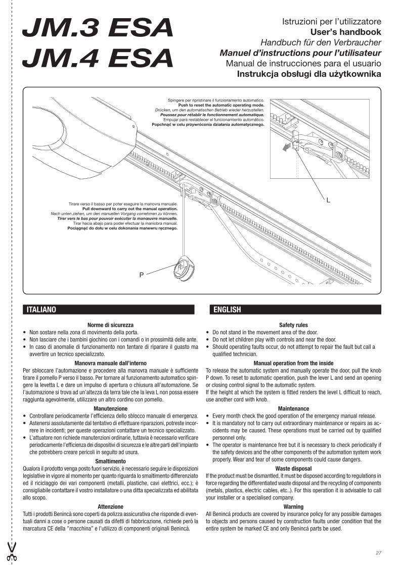
Norme di sicurezza• Non sostare nella zona di movimento della porta.• Non lasciare che i bambini giochino con i comandi o in prossimità delle ante.• In caso di anomalie di funzionamento non tentare di riparare il guasto ma
avvertire un tecnico specializzato.
Manovra manuale dall’internoPer sbloccare l’automazione e procedere alla manovra manuale è sufficiente tirare il pomello P verso il basso. Per tornare al funzionamento automatico spin-gere la levetta L e dare un impulso di apertura o chiusura all’automazione. Se l’automazione si trova ad un’altezza da terra tale che la leva L non possa essere raggiunta agevolmente, utilizzare un altro cordino con pomello.
Manutenzione• Controllare periodicamente l’efficienza dello sblocco manuale di emergenza.• Astenersi assolutamente dal tentativo di effettuare riparazioni, potreste incor-
rere in incidenti; per queste operazioni contattare un tecnico specializzato.• L’attuatore non richiede manutenzioni ordinarie, tuttavia è necessario verificare
periodicamente l’efficienza dei dispositivi di sicurezza e le altre parti dell’impianto che potrebbero creare pericoli in seguito ad usura.
SmaltimentoQualora il prodotto venga posto fuori servizio, è necessario seguire le disposizioni legislative in vigore al momento per quanto riguarda lo smaltimento differenziato ed il riciclaggio dei vari componenti (metalli, plastiche, cavi elettrici, ecc.); è consigliabile contattare il vostro installatore o una ditta specializzata ed abilitata allo scopo.
AttenzioneTutti i prodotti Benincà sono coperti da polizza assicurativa che risponde di even-tuali danni a cose o persone causati da difetti di fabbricazione, richiede però la marcatura CE della ”macchina” e l’utilizzo di componenti originali Benincà.
Safety rules• Do not stand in the movement area of the door.• Do not let children play with controls and near the door.• Should operating faults occur, do not attempt to repair the fault but call a qualified technician.
Manual operation from the insideTo release the automatic system and manually operate the door, pull the knob P down. To reset to automatic operation, push the lever L and send an opening or closing control signal to the automatic system.If the height at which the system is fitted renders the level L difficult to reach, use another cord with knob.
Maintenance• Every month check the good operation of the emergency manual release.• It is mandatory not to carry out extraordinary maintenance or repairs as ac-
cidents may be caused. These operations must be carried out by qualified personnel only.
• The operator is maintenance free but it is necessary to check periodically if the safety devices and the other components of the automation system work properly. Wear and tear of some components could cause dangers.
Waste disposalIf the product must be dismantled, it must be disposed according to regulations in force regarding the differentiated waste disposal and the recycling of components (metals, plastics, electric cables, etc..). For this operation it is advisable to call your installer or a specialised company.
WarningAll Benincá products are covered by insurance policy for any possible damages to objects and persons caused by construction faults under condition that the entire system be marked CE and only Benincá parts be used.
ITALIANO ENGLISH
L
Spingere per ripristinare il funzionamento automatico.Push to reset the automatic operating mode.
Drücken, um den automatischen Betrieb wieder herzustellen.Poussez pour rétablir le fonctionnement automatique.
Empujar para restablecer el funcionamiento automático.Popchnąć w celu przywrócenia działania automatycznego.
Tirare verso il basso per poter eseguire la manovra manuale.Pull downward to carry out the manual operation.
Nach unten ziehen, um den manuellen Vorgang vornehmen zu können.Tirer vers le bas pour pouvoir exécuter la manœuvre manuelle.
Tirar hacia abajo para poder efectuar la maniobra manual.Pociągnąć do dołu w celu dokonania manewru ręcznego.
P
28
Sicherheitsvorschriften• Nicht im Öffnungsbereich verweilen.• Kinder nicht mit den Steuerungen oder in der Nähe des Tores spielen las-
sen.• Bei Funktionsausfällen nicht versuchen, den Schaden selber zu beheben,
sondern den Techniker rufen.
Manuelle Betätigung von InnenUm die Automatik zu entsichern und sie von Hand zu steuern, genügt es den Kugelgriff P nach unten zu ziehen. Um den automatischen Betrieb wieder herzustellen, den Hebel L drücken und den Impuls zum Öffnen oder Schließen geben.Falls die automatische Vorrichtung zu hoch installiert ist und vom Boden nicht leicht erreicht werden kann, eine Schnur mit Kugelgriff verwenden.
Wartung• Monatliche Kontrolle der manuellen Notentriegelung• Es ist absolut untersagt, selbstständig Sonderwartung oder Reparaturen
vorzunehmen, da Unfälle die Folge sein können; wenden Sie sich an den Techniker.
• Der Antrieb braucht keine ordentliche Unterhaltung aber es ist periodisch notwendig die Leistungsfähigkeit der Sicherheitsvorrichtungen und die andere Teile des Anlages zu prüfen. Sie könnten durch Abnutzung Gefaht hervorbringen.
EntsorgungWird das Gerät außer Betrieb gesetzt, müssen die gültigen Gesetzesvorschriften zur differenzierten Entsorgung und Wiederverwendung der Einzelkomponenten, wie Metall, Plastik, Elektrokabel, usw., beachtet werden. Rufen Sie Ihren Instal-lateur oder eine Entsorgungsfirma.
AchtungAlle Produkte BENINCA’ wurden mit einem Versicherungsschein versehen, der alle eventuellen Schäden an Dingen oder Personen abdeckt, die durch Herstellungsdefekte hervorgerufen wurden, vorausgesetzt, das Gerät besitzt die Kennzeichnung EU und es wurden original BENINCA’ Einzelkomponenten verwendet.
Normes de sécurité• Ne pas stationner dans la zone de mouvement de la porte.• Ne laissez pas les enfants jouer avec les commandes ou à proximité de la
porte.• En cas d’anomalies de fonctionnement, n’essayez pas de réparer la panne
mais contactez un technicien spécialisé.
Manœuvre manuelle de l’intérieurPour débloquer l’automatisme et passer à la manœuvre manuelle il suffit de tirer la poigné P vers le bas. Pour revenir au fonctionnement automatique poussez le levier L et donner une impulsion d’ouverture ou de fermeture à l’automatisme.Si l’automatisme se trouve à une hauteur du sol telle que le levier L ne peut pas être atteint facilement, servez-vous d’un autre cordon muni d’un gland.
Maintenance• Contrôler tous les mois le bon état du déverrouillage manuel d’urgence.• Ne tenter aucune réparation ou intervention qui pourrait s’avérer dangereuse.
Contactez impérativement un technicien spécialisé pour ce type d’opéra-tion.
• L’operateur ne demande pas d’entretien particulier mais il faut vérifier périodiquement l’efficacité des dispositifs de sécurité ainsi que les autres points de l’installation qui pourraient créer des risques dû à l’usure.
DémolitionAu cas où le produit serait mis hors service, il est impératif de se conformer aux lois en vigueur pour ce qui concerne l’élimination différenciée et le recyclage des différents composants (métaux, matières plastiques câbles électriques, etc...) contactez votre installateur ou une firme spécialisée autorisée à cet effet.
AttentionTous les produits Benincà sont couverts par une police d’assurance qui répond d’éventuels préjudices corporels ou matériels provoqués à cause de défauts de fabrication, mais qui requiert toutefois le marquage CE de la “machine” et l’utilisation de pièces de rechange d’origine Benincà.
Normas de seguridad• No pararse en la zona de movimiento de la puerta.• No dejar que los niños jueguen con los mando o en proximidad de la puerta.• En caso de anomalías de funcionamiento no intentar reparar la avería sino
que avisar a un técnico espe-cializado.
Maniobra manual desde el interiorPara desbloquear la automatización y proceder a la maniobra manual basta tirar de la empuñadura P hacia abajo. Para volver al funcionamiento automá-tico se debe empujar la palanca L y dar un impulso de apertura o cierre a la automatización.Si la automatización se encuentra a una altura con respecto al suelo tal que no se logre alcanzar fácilmente la palanca L, utilizar otro cordelillo con em-puñadura.
Mantenimiento• Controlar periodicamente la eficiencia del desbloqueo manual de emergencia.• Abstenerse absolutamente de intentar efectuar reparaciones, podrán incurrir en
accidentes; para estas operaciones contactar con un técnico especializado.• El operador no requiere mantenimiento habitual, no obstante es necesario
verificar periódicamente la eficiencia de los dispositivos de seguridad y las otras partes de la instalación que pudiesen crear peligros a causa del desgaste.
Eliminación de aguas suciasCada vez que el producto esté fuera de servicio, es necesario seguir las disposi-ciones legislativas en vigor en ese momento en cuanto concierne a la eliminación de suciedad y al reciclaje de varios componentes (metales, plásticos, cables eléctricos, etc.), es aconsejable contactar con su instalador o con una empresa especializada y habilitada para tal fin.
AtenciónTodos los productos Benincà están cubiertos por una póliza de seguros que responde de eventuales daños a personas o cosas, causados por defectos de fabricación, requiere sin embargo la marca CE de la ”máquina” y la utilización de componentes originales Benincà.
Normy bezpieczeństwa• Nie przestawać w obszarze przemieszczania bramy.• Nie dopuszczać aby dzieci bawiły się sterownikami lub w pobliżu skrzydeł
bramy.• W przypadku niewłaściwego funkcjonowania nie próbować samemu doko-
nywania naprawy, tylko zwrócić się do wykwalifikowanego technika.
Manewr ręczny od wewnątrzW celu odblokowania urządzenia automatycznego w trybie manewru ręcznego wystarczy pociągnąć uchwyt kulisty P do dołu. W celu powrotu do działania automatycznego należy popchnąć dźwignię L i dać impuls automatycznego otwarcia lub zamknięcia. Jeżeli automatyzm znajduje się na takiej wysokości od ziemi, która uniemożliwia dosięgnięcie dźwigienki L, należy użyć drugiej linki (prętu) z gałką.
Konserwacja• Sprawdzać okresowo sprawność działania obsługiwanego ręcznie odbloko-
wującego mechanizmu bezpieczeństwa.• Nie dokonywać samodzielnych napraw, ponieważ grozi to wypadkiem;
zwrócić się do wykwalifikowanego technika.• Siłownik nie wymaga konserwacji, wystarczy okresowo sprawdzić sprawność
działania mechanizmów bezpieczeństwa oraz niektórych elementów instalacji mogących stanowić zagrożenie z racji na ich stan zużycia.
DemolowanieW przypadku gdy produkt nie nadaje się już do użytku konieczne staje się przekazanie go, zgodnie z obowiązującymi w danym momencie normami, do zróżnicowanego demolowania i odzyskiwania niektórych elementów (metale, plastyk, przewody elektryczne itp.); zaleca się skontaktować z instalatorem urządzenia lub firmą specjalistyczną, autoryzowaną do tego rodzaju prac.
UwagaWszystkie produkty Benincà objęte są polisą ubezpieczeniową na pokrycie szkód poniesionych przez rzeczy lub osoby w wyniku wad produkcyjnych, pod warun-kiem że urządzenia posiadają oznakowanie CE i oryginalne części Benincà.
DEUTSCH
FRANÇAIS
ESPAŇOL
POLSKY
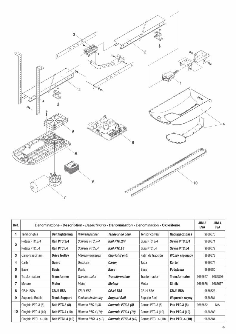
29
4
7
5
9
6
8
10
1
2
2
3
Ref. Denominazione - Description - Bezeichnung - Dénomination - Denominación - OkreślenieJIM 3ESA
JIM 4ESA
1 Tendicinghia Belt tightening Riemenspanner Tendeur de cour. Tensor correa Naciągacz pasa 9686670
2Rotaia PTC.3/4 Rail PTC.3/4 Schiene PTC.3/4 Rail PTC.3/4 Guía PTC.3/4 Szyna PTC.3/4 9686671
Rotaia PTC.L4 Rail PTC.L4 Schiene PTC.L4 Rail PTC.L4 Guía PTC.L4 Szyna PTC.L4 9686672
3 Carro trascinam. Drive trolley Mitnehmerwagen Chariot d'entr. Patín de tracción Wóżek ciągnący 9686673
4 Carter Guard Gehäuse Carter Tapa Karter 9686674
5 Base Basis Basis Base Base Podstawa 9686680
6 Trasformatore Transformer Transformator Transformateur Trasformador Transformator 9686647 9686826
7 Motore Motor Motor Moteur Motor Silnik 9686676 9686677
8 CP.J4 ESA CP.J4 ESA CP.J4 ESA CP.J4 ESA CP.J4 ESA CP.J4 ESA 9686825
9 Supporto Rotaia Track Support Schienenhalterung Support Rail Soporte Riel Wspornik szyny 9686681
10
Cinghia PTC.3 (8) Belt PTC.3 (8) Riemen PTC.3 (8) Courroie PTC.3 (8) Correa PTC.3 (8) Pas PTC.3 (8) 9686682 N/A
Cinghia PTC.4 (10) Belt PTC.4 (10) Riemen PTC.4 (10) Courroie PTC.4 (10) Correa PTC.4 (10) Pas PTC.4 (10) 9686683
Cinghia PTCL.4 (10) Belt PTCL.4 (10) Riemen PTCL.4 (10) Courroie PTCL.4 (10) Correa PTCL.4 (10) Pas PTCL.4 (10) 9686684


AUTOMATISMI BENINCÀ SpA - Via Capitello, 45 - 36066 Sandrigo (VI) - Tel. 0444 751030 r.a. - Fax 0444 759728