Embed Size (px)
Citation preview

L06-1
University of Virginia Physics Department PHYS 2419, Fall 2010
Name ________________________ Date__________ Partners
Lab 6 - ELECTRON
CHARGE-TO-MASS RATIO
OBJECTIVES
• To understand how electric and magnetic fields impact an
electron beam
• To experimentally determine the electron charge-to-mass ratio
OVERVIEW
In this experiment, you will measure e/m, the ratio of the electron’s
charge e to its mass m. Given that it is also possible to perform a
measurement of e alone (the Millikan Oil Drop Experiment), it is
possible to obtain the value of the mass of the electron, a very
small quantity.
If a particle carrying an electric charge q moves with a velocity v
in a magnetic field B that is at a right angle to the direction of
motion, it will experience the magnetic part of the Lorentz force:
F = qv x B (1)
Which, because of the vector product, is always perpendicular to
both the magnetic field and the direction of motion. A constant
force that is always perpendicular to the direction of motion will
cause a particle to move in a circle. We will use this fact to
determine e/m of the electron by measuring the radius of that
circle. To this end we must:
• produce a narrow beam of electrons of known energy,
• produce a uniform magnetic field,
• find a way to measure the radius r of the circular orbit of the
electrons in that magnetic field,
and
• find the relation between that radius and the ratio e/m.
We will discuss these tasks in order.
The Electron Beam
When one heats a piece of metal, say a wire, to 1,000 K or beyond,
electrons will “boil off” from its surface. If one surrounds the wire

L06-2 Lab 6 - Electron Charge-to-Mass Ratio
University of Virginia Physics Department PHYS 2419, Fall 2011
with a positively charged electrode, an anode, the electrons will be
attracted to it and move radially outward as indicated in Figure 1.
On their way to the anode they will acquire a kinetic energy
eVmvEk
==2
21 , (2)
where V is the potential difference, or voltage, between the heated
filament, called the cathode, and the anode.
Figure 1
Most of the electrons will strike the anode. However, if one cuts a
narrow slit into the anode, those electrons that started out toward
the slit will exit through it as a narrow beam with a kinetic energy
Ek.
The Magnetic Field
According to Ampere’s law a wire
carrying a current I is surrounded by
a magnetic field B, as shown in
Figure 2. If the wire is bent into a
circle the field lines from all sides
reinforce each other at the center,
creating an axial field (see Figure 3).
Usually one will not use a single
loop of wire to create a field but a
coil with many turns.
Figure 3 Magnetic field of a wire loop.
Figure 2 Magnetic field of
a straight wire.

Lab 6 - Electron Charge-to-Mass Ratio L06-3
University of Virginia Physics Department PHYS 2419, Fall 2011
If one uses two coaxial coils of radius R that are a distance d apart,
as shown in Figure 4, the field at the center point between the coils
will be nearly homogeneous1. H. von Helmholtz (1821-1894)
realized that there remains a free parameter, namely the coil
separation d, that can still be adjusted. He showed that when
d = R, the result is a particularly homogeneous field in the central
region between the coils.2 Since that time Helmholtz coils have
been used when there is a need for homogeneous magnetic fields.
Figure 4 Magnetic field B of a pair of Helmholtz coils.
One can show that the field in the center of a Helmholtz coil is
given by
,55
8 0 IR
NB
=
µ (3)
where I is the current flowing through both coils, R is their mean
radius, N is the number of turns of wire in each coil, and
µ0 = 4π × 10-7
T·m/A is the permeability constant.
The Electron Orbit
Experiments like the one that you will perform have been used to
measure the mass of charged particles with great precision. In these
experiments the particles move in a circular arc whose beginning and
end are measured very accurately in a near perfect vacuum. For our
simple experiment we cannot go to such lengths and a simple
expedient has been used to make the electron orbit visible. The bulb
surrounding the electron source is filled with helium vapor. When the
electrons collide with the atoms, the atoms emit light so that one can
follow the path of the electron beam. These collisions will diminish
1 The symmetry of the arrangement makes the first derivative of the field with respect to
the axial direction vanish.
2 The second derivative vanishes as well.

L06-4 Lab 6 - Electron Charge-to-Mass Ratio
University of Virginia Physics Department PHYS 2419, Fall 2011
the accuracy of the experiment but it remains adequate for our
purposes.
A particle moving in a circle of radius r must be held there by a
centripetal force
r
mvFc
2
= . (4)
In our case, that centripetal force is provided by the magnetic part
of the Lorentz force, Equation (1), hence
r
mvevB
2
= (5)
This equation contains the velocity v, which we can eliminate by
using Equation (2). Rewriting Equation (2), we find
m
eVv
2= (6)
and hence
2
2 2 2 2 2 2
0
2 125
32
e V R V
m B r N I rµ
= =
(7)
In this equation, V is the voltage between cathode and anode and r
is the mean radius of the circular electron orbit, both of which can
be measured, and B is the magnetic field through which the
electrons pass. We know the magnetic field at the center of the
Helmholtz coil, which can be obtained, using Equation (3), from a
measurement of the current through the coils, the dimension of the
coils and the number of turns. The magnetic field does not change
very much away from the center of the coils.
INVESTIGATION 1: FINDING e/m
For this investigation, you will need the following:
• Helmholtz coil with e/m glass tube
• Bar magnet
• Meter stick
Activity 1-1: The e/m Apparatus
In this activity, you will familiarize yourself with the setup you
will be using.

Lab 6 - Electron Charge-to-Mass Ratio L06-5
University of Virginia Physics Department PHYS 2419, Fall 2011
Figure 5 e/m Apparatus
1. Turn the main power on. The unit will perform a self test
lasting no more than 30 s. Do not do anything with the unit
during the self test. When it is finished, the coil current display
will be stabilized and indicate “000”. The unit is now ready to
use, but note that there is a ten minute warm-up time before
you should take final measurements. You can go ahead and
proceed with the remainder of this procedure.
2. Look in the center of the Helmholtz coils for the glass tube.
The electrons will follow circular orbits inside this evacuated
glass tube. The tube has a tiny bit of helium vapor inside of it.
The energetic electrons collide with and ionize the helium
atoms, causing the gas to glow and making the beam visible.
The glass tube is extremely fragile, so be very careful around it.
3. Locate the grid and anode inside the glass tube. It is the pair of
vertically oriented metal cylinders with a gap between them.
At its top and center is the filament or cathode that will be
heated by a current to emit the electrons.
4. You should now be able to see the filament (wires that are
glowing orange due to being heated).

L06-6 Lab 6 - Electron Charge-to-Mass Ratio
University of Virginia Physics Department PHYS 2419, Fall 2011
Figure 6 Grid and Anode
5. There are three separate electrical circuits: 1) to heat the
filament/cathode (over which you have no control); 2) to apply
a voltage between cathode and anode (denoted as Accelerating
Voltage on the unit); 3) to supply the current (denoted as Coil
Current) for the Helmholtz coils.
6. Measure the diameter of the Helmholtz coils in several places
and take the average. Record the mean radius R below.
Radius R: _______________
7. Measure the mean separation d between the coils. You may
want to average several measurements here also.
Coil separation d: __________________
Verify that d R≈ .
8. The manufacturer states that there are 130 turns in each coil.
9. Calculate the “constant of proportionality” between the current
passing through the Helmholtz coils and the magnetic field
produced. You will need the above parameters to do this.
Look at Equation (3).
BHelmoltz (Tesla) = __________ × I (amps)
Lab 6 - Electron Charge-to-Mass Ratio L06-7
University of Virginia Physics Department PHYS 2419, Fall 2011
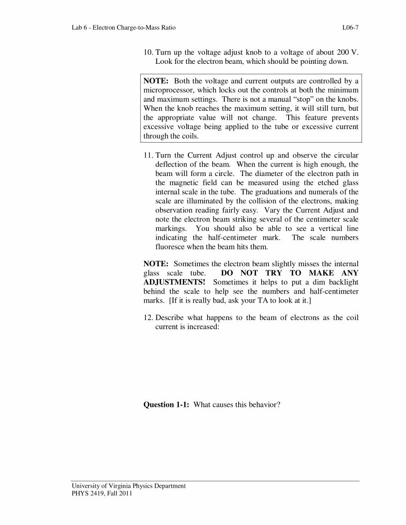
10. Turn up the voltage adjust knob to a voltage of about 200 V.
Look for the electron beam, which should be pointing down.
NOTE: Both the voltage and current outputs are controlled by a
microprocessor, which locks out the controls at both the minimum
and maximum settings. There is not a manual “stop” on the knobs.
When the knob reaches the maximum setting, it will still turn, but
the appropriate value will not change. This feature prevents
excessive voltage being applied to the tube or excessive current
through the coils.
11. Turn the Current Adjust control up and observe the circular
deflection of the beam. When the current is high enough, the
beam will form a circle. The diameter of the electron path in
the magnetic field can be measured using the etched glass
internal scale in the tube. The graduations and numerals of the
scale are illuminated by the collision of the electrons, making
observation reading fairly easy. Vary the Current Adjust and
note the electron beam striking several of the centimeter scale
markings. You should also be able to see a vertical line
indicating the half-centimeter mark. The scale numbers
fluoresce when the beam hits them.
NOTE: Sometimes the electron beam slightly misses the internal
glass scale tube. DO NOT TRY TO MAKE ANY
ADJUSTMENTS! Sometimes it helps to put a dim backlight
behind the scale to help see the numbers and half-centimeter
marks. [If it is really bad, ask your TA to look at it.]
12. Describe what happens to the beam of electrons as the coil
current is increased:
Question 1-1: What causes this behavior?

L06-8 Lab 6 - Electron Charge-to-Mass Ratio
University of Virginia Physics Department PHYS 2419, Fall 2011
13. Set the coil current to 1.7 A. Adjust the accelerating voltage
while looking at the electron beam path..
Question 1-2: What do you observe as the accelerating voltage is
changed while keeping the coil current constant? Explain why this
occurs.
14. While the electron beam is somewhere near the middle of the
glass rod, use the bar magnet to see how it affects the electron
beam.
Question 1-3: Describe what you observe as you move the bar
magnet around. Can you produce a helical path for the electron?
Can you see why you want to keep spurious magnetic fields away
from the electron beam?
Question 1-4: The nominal value for the apparatus you will be
using is 1.3 mT (milliTesla). The Earth’s magnetic field is
approximately 0.1 mT and is pointing into the ground at an angle
of about 58° with respect to the horizontal. Discuss how much
difficulty the Earth’s magnetic field will cause in your experiment.
Lab 6 - Electron Charge-to-Mass Ratio L06-9
University of Virginia Physics Department PHYS 2419, Fall 2011
Question 1-5: If it were possible to arbitrarily orient the
apparatus, in what direction (parallel, anti-parallel, perpendicular,
other) should it be aligned in order to minimize the effects of the
Earth’s magnetic field? Explain your reasoning.
NOTE: We cannot compensate for the Earth’s magnetic field with
this apparatus.
15. Make sure you place the bar magnet at the other end of the
table from your apparatus to minimize any possible effects.
Activity 1-2: Measurement Of Charge-To-Mass Ratio
NOTE: The electrons collide with the gas atoms that were
introduced to make the beam visible. Unavoidably, the electrons
lose some energy in the collisions (that make the beam visible).
In order to minimize this effect, you should concentrate on those
electrons that have the highest energy: those at the outer edge of
the beam (largest radius). Ask your Instructor if you are
uncertain about this.
1. We will make measurements for the electrons moving in
various circular orbits. You will write down the diameter of
the path by reading the illuminated tube. You will need these
in order to determine e/m from Equation (7).
2. Set the anode voltage to 300 V. Change the coil current until
the beam hits the 5 cm mark. This will be the diameter, not
the radius of the orbit.
3. Record the coil current and diameter in Table 1-1. Decrease
the coil current to go through, in turn, each 0.5 cm mark on the
scale. The 0.5 cm marks are a vertical line between the
numbered cm marks. This can proceed quite rapidly by one
person observing the beam while changing the coil current and
another person filling in Table 1-1.
4. Proceed in turn to observe and record data for the other
accelerating voltages in Table 1-1. Sometimes the beam will
L06-10 Lab 6 - Electron Charge-to-Mass Ratio
University of Virginia Physics Department PHYS 2419, Fall 2011
physically not be present for every position listed in Table 1-1.
Leave the table blank when this occurs.
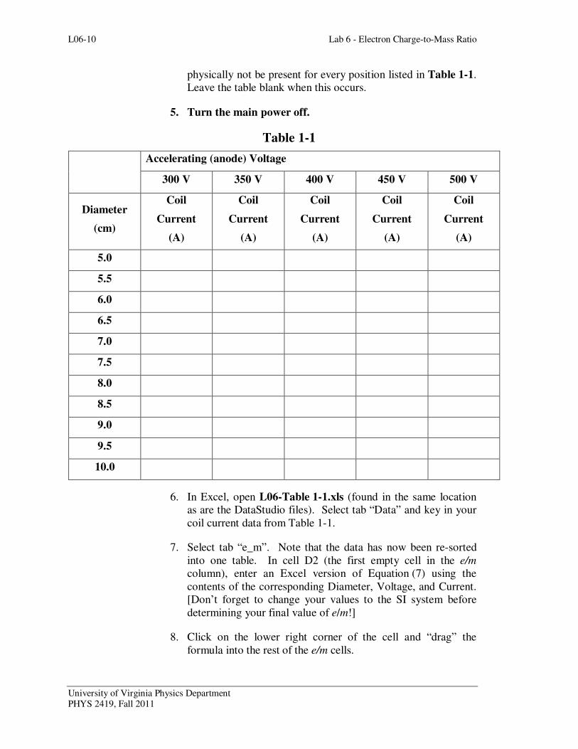
5. Turn the main power off.
Table 1-1
6. In Excel, open L06-Table 1-1.xls (found in the same location
as are the DataStudio files). Select tab “Data” and key in your
coil current data from Table 1-1.
7. Select tab “e_m”. Note that the data has now been re-sorted
into one table. In cell D2 (the first empty cell in the e/m
column), enter an Excel version of Equation (7) using the
contents of the corresponding Diameter, Voltage, and Current.
[Don’t forget to change your values to the SI system before
determining your final value of e/m!]
8. Click on the lower right corner of the cell and “drag” the
formula into the rest of the e/m cells.
Accelerating (anode) Voltage
300 V 350 V 400 V 450 V 500 V
Diameter
(cm)
Coil
Current
(A)
Coil
Current
(A)
Coil
Current
(A)
Coil
Current
(A)
Coil
Current
(A)
5.0
5.5
6.0
6.5
7.0
7.5
8.0
8.5
9.0
9.5
10.0

Lab 6 - Electron Charge-to-Mass Ratio L06-11
University of Virginia Physics Department PHYS 2419, Fall 2011
9. Set up column E to be the difference between your value of e/m
and the accepted one (1.759 x 10¹¹
C/kg).
10. Average all your results in Excel to obtain a mean value for
e/m.
e/m:
11. Find the statistical uncertainty of your average value. [Hint:
Think “standard error of the mean”]
Uncertainty:
12. Compare your value with the accepted value of e/m.
Error: ________%
Question 1-5: Discuss well your result compare with the accepted
value.
13. Print out one data table for your group. You only need one
printout per group.
Activity 1-3: Investigation of Systematic Uncertainty
It is useful in an experiment like this to see if there are systematic
uncertainties that might affect your final results. From
Equation (7) [and a review of Appendix C, of course!] we can see
that the relative uncertainty in our experimental determination of
e/m due to uncertainties in our measured quantities (V, I, R, and r)
is given by:
2 2 2 2 2
2 2 2e m V I R r
e m V I R r
σ σ σ σ σ = + + +
(8)
L06-12 Lab 6 - Electron Charge-to-Mass Ratio
University of Virginia Physics Department PHYS 2419, Fall 2011
Question 1-6: With Equation (8) in mind, discuss possible
sources of uncertainty in your experiment.
1. It may be possible that we may learn something about our
uncertainties if we compare the values of e/m versus our
parameters. Because we have our data in Excel, it is quite easy
to do that.
2. Plot all your values of e/m versus a) accelerating voltage, b)
coil current, and c) orbit radius. Produce trendline fits for your
data.
3. Print out one copy each of these graphs and include them in
your report.
Question 1-6: Look carefully at the three plots you just made and
at your trendlines. Do you see any patterns? Could these possibly
indicate any systematic problems? Discuss these possible
uncertainties and how you might be able to correct for them or
improve the experiment. List any other systematic uncertainties
you can think of and discuss.
PLEASE CLEAN UP YOUR LAB AREA AND MAKE SURE
THAT THE POWER IS OFF!