Embed Size (px)
Citation preview
EECS 473—Advanced Embedded Systems Lab 1: An Introduction to Arduino
Page 1 of 13
Lab 1: An Introduction to Arduino: From Flashing Lights to a Wireless Robot!
During the relatively short and time—consuming first few weeks of class, we will be working to get
you familiar with a number of different platforms and tools. Those include using and developing for the Arduino environment (an easy-to-use and low-end platform), Linux device driver writing, PCB design, and working with multiple embedded platforms at once.
This lab will focus on making a rapid prototype and learning the Arduino environment.
The goal of prototyping is to achieve system functionality identical to the desired
system or as close to it as necessary in key areas to determine system performance and cost prior to committing to a final solution. What this means is that during prototyping we modify the design to get a decent approximation of the real system at (hopefully) a fraction of the cost. This approximation may be a goal in itself, for example for the purposes of evaluating a design. The design modifications (or shifts) performed during prototyping can take on different forms, each leading to a different form of prototyping.1
1. Prelab
1. Read the lab from start to finish. 2. Read http://arduino.cc/en/Guide/Environment 3. Read http://www.arduino.cc/en/Main/ArduinoBoardDuemilanove 4. Get familiar with Arduino, its IDE, and the associated syntax. Then take a look at File>Examples
to get a sense of what has already been done. Answer the following questions:
Q1. In Arduino-speak, what is a shield? Identify at least two shields, where you can get them from and how much they cost.
Q2. What processor family does Arduino primarily use? Name another programming environment that is commonly used to program that family. What are the pros and cons of Arduino compared to that environment?
Q3. In Arduino-speak, what is a “sketch”?
Q4. Look over http://arduino.cc/en/Tutorial/Foundations. Much of it is pretty basic. a. What does pinMode() do and what are the options associated with it? b. How is pin 13 different than most?
Q5. Look at http://arduino.cc/en/Reference/HomePage a. What does delay() do? b. What does analogRead() do?
Q6. What is ZigBee and where is it generally used? What is an XBee?
1 Taken from http://www.signum.com/Signum.htm?p=art02.htm with only minor changes, though the ideas
expressed are pretty standard.
EECS 473—Advanced Embedded Systems Lab 1: An Introduction to Arduino
Page 2 of 13
Q7. Read https://learn.sparkfun.com/tutorials/exploring-xbees-and-xctu/configuring-networks and https://support.metageek.com/hc/en-us/articles/203845040-ZigBee-and-WiFi-Coexistence (you may need to do some other reading to answer theses…) a. Explain what a channel and PAN ID are and how they are different. b. Two XBees need to be on the same channel and have the same PAN in order to
communicate. i. Do two XBees on the same channel but with a different PAN interfere with each other in
any way? ii. What about two XBees with the same PAN but different channels?
c. What is the MY address and destination address? How are they used? d. When might you want to have devices with different addresses but the same channel and
PAN?
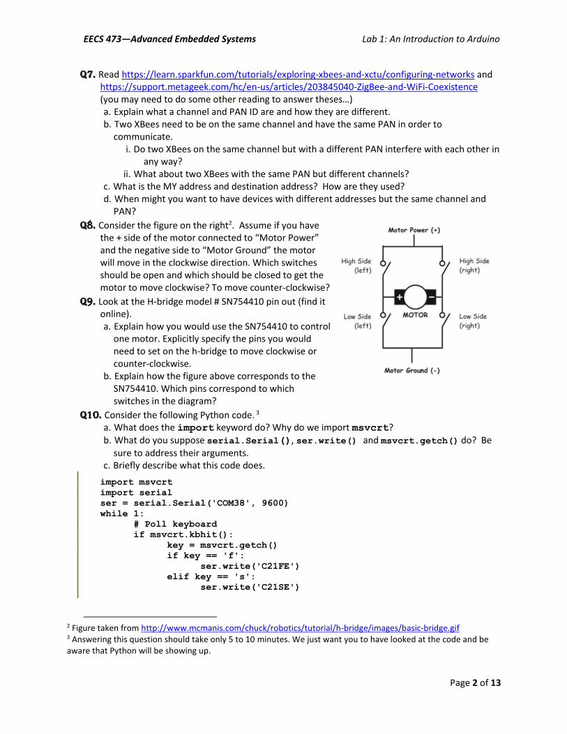
Q8. Consider the figure on the right2. Assume if you have the + side of the motor connected to “Motor Power” and the negative side to “Motor Ground” the motor will move in the clockwise direction. Which switches should be open and which should be closed to get the motor to move clockwise? To move counter-clockwise?
Q9. Look at the H-bridge model # SN754410 pin out (find it online). a. Explain how you would use the SN754410 to control
one motor. Explicitly specify the pins you would need to set on the h-bridge to move clockwise or counter-clockwise.
b. Explain how the figure above corresponds to the SN754410. Which pins correspond to which switches in the diagram?
Q10. Consider the following Python code. 3 a. What does the import keyword do? Why do we import msvcrt?
b. What do you suppose serial.Serial(), ser.write() and msvcrt.getch() do? Be sure to address their arguments.
c. Briefly describe what this code does.
import msvcrt
import serial
ser = serial.Serial('COM38', 9600)
while 1:
# Poll keyboard
if msvcrt.kbhit():
key = msvcrt.getch()
if key == 'f':
ser.write('C21FE')
elif key == 's':
ser.write('C21SE')
2 Figure taken from http://www.mcmanis.com/chuck/robotics/tutorial/h-bridge/images/basic-bridge.gif 3 Answering this question should take only 5 to 10 minutes. We just want you to have looked at the code and be aware that Python will be showing up.
EECS 473—Advanced Embedded Systems Lab 1: An Introduction to Arduino
Page 3 of 13
2. Inlab
The purpose of this lab is to gain a basic familiarity with the Arduino environment. Arduinos are a standard Atmel microcontroller with a really simplified programming environment. You should find that doing basic prototyping is really straightforward in this environment. In fact, Arduinos are really targeted toward non-programmers. This environment is important for you, a professional embedded engineer, to learn for three reasons:
It is a powerful tool for quickly prototyping devices and getting basic interfacing working. There is a massive amount of device support out there and this can be a really useful way to either get a quick-and-dirty device created for someone or just for getting a proof-of-concept created.
It provides some really solid interfaces so that people who don’t understand the hardware can none-the-less use it. This can provide you with something to aspire to in your own designs for hardware interfaces.
When others want to do basic embedded systems work without the needed background to do the job “right”, you can point them to the Arduino environment and perhaps provide a bit of support.
In order to acquire that background, you will start by writing the “hello world” of embedded systems: getting a light blinking. We’ll then move quickly to reading analog input, getting wireless communication working, controlling an H-bridge and getting a wireless vehicle up and running. All in this one lab! You might find https://www.arduino.cc/en/Reference/HomePage useful.
Note: some of these sections are significantly more guided than others. We have tried to find the
right balance of having you searching and reading on your own while providing enough information that you aren’t likely to waste your time in trivialities. So some sections (such as configuring your XBee chips) are very directed (we don’t want you wasting time figuring out their UI), while others more-or-less consist of “just go do it”.
Part 1—Das Blinkenlights4
Let’s get familiar with the Arduino programming environment. Open Arduino by double clicking the “infinity symbol.” This should bring you to a blank “sketch”. We are going to make a simple little sketch for blinking the LED connected to pin 13. Note that we won’t need any includes or defines for this part; you only need to define a setup and loop function. This is because the Arduino IDE transforms your sketch into a valid C++ program by adding the following lines of code:
#include "WProgram.h" // Definitions relevant to Arduino
void main() {
setup();
while(1) {
loop();
}
}
4 See http://en.wikipedia.org/wiki/Blinkenlights if you are curious why this section is so named.
EECS 473—Advanced Embedded Systems Lab 1: An Introduction to Arduino
Page 4 of 13
In setup, use pinMode (which you read about in the prelab) to make pin 13 an output. In loop(),
use digitalWrite() and delay() to cause the LED to blink at 1 Hz with a 50% duty cycle. Note that both setup() and loop() should be declared as “void”.
Now that the code is written, check to see if it compiles. Press the play icon named “Verify.” This
will check for errors and compile your code. After the program compiles successfully, we still need to upload the program to the board. Connect the Arduino via the USB port. Select the correct board (should be fairly obvious) and port (might require you to go to the control panel and look at the device
drivers). Then click the second icon on the upload icon . If you get an error, check to be sure you’ve selected the correct device and port. If you cannot select a different COM port and cannot program your board, you may need to quit Arduino and restart it with the board unplugged. If that does not work please power cycle your computer. You’ve written your first Arduino program!
G1. Have your GSI check that your code is flashing the LED at 1Hz.
Using a breadboard, connect four digital outputs to four LEDs so you can light each of them individually. Include a ~1 KOhm resistor in series with each LED. Also make sure to share the Arduino’s ground with the LED’s. To recap, from a digital pin you will connect a resistor, the resistor will connect to an LED, and the LED will be connected to ground on the Arduino board. Write a quick test sketch to be sure you can individually control each LED. One interesting thing about the Arduino environment is that you do have access to the processor and its low-level interfaces just as if you were coding in C (because you are). Check out http://www.arduino.cc/en/Reference/PortManipulation and use the DDRx and PORTx to change the LEDs all at once.
For the last step of this section, hook up a potentiometer (pot) which we’ve supplied such that the
middle pin of the pot is connected to one of the analog inputs found on the board while the other two pins on the pot are connected to 0V and 5V. Look through the Arduino documentation about how to work with analog inputs and make it so the number of LEDs lit is about proportional to how far the pot is turned (or, if you prefer, the MSBs of the value are displayed on the LEDs). For the analog input you do not need to use the DDRx and PORTx interface.
G2. Have your GSI check that your LEDs are properly controlled by the potentiometer. Show the GSI that you are using DDRx and PORTx to control the LEDs.
Part 2—XBee Wireless
For this part of the lab, you will create a wireless serial link (UART) between the workstation and the Arduino with a pair of Digi XBee radio modules. To start, you need to configure the XBee pair with a unique channel number to avoid interference with your neighbors. To do this, you will set the channel number to your station number (on the workstation face) plus 12 in hex. For example, station 1 would be 13 or “D” in hex, station 10 would be 22 or “16” in hex.
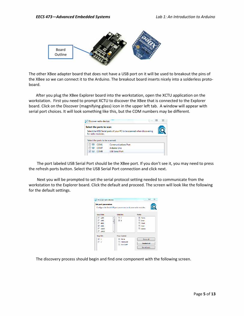
Let’s get started. Insert one of your XBees into an XBee Explorer. This is one of the XBee adapter
boards that has a USB port on it. Be sure to line up pin 1 of the XBee with pin 1 of the XBee Explorer socket or simply follow board outline matching the shape of the XBee chip.
EECS 473—Advanced Embedded Systems Lab 1: An Introduction to Arduino
Page 5 of 13
The other XBee adapter board that does not have a USB port on it will be used to breakout the pins of the XBee so we can connect it to the Arduino. The breakout board inserts nicely into a solderless proto-board.
After you plug the XBee Explorer board into the workstation, open the XCTU application on the
workstation. First you need to prompt XCTU to discover the XBee that is connected to the Explorer board. Click on the Discover (magnifying glass) icon in the upper left tab. A window will appear with serial port choices. It will look something like this, but the COM numbers may be different.
The port labeled USB Serial Port should be the XBee port. If you don’t see it, you may need to press
the refresh ports button. Select the USB Serial Port connection and click next. Next you will be prompted to set the serial protocol setting needed to communicate from the
workstation to the Explorer board. Click the default and proceed. The screen will look like the following for the default settings.
The discovery process should begin and find one component with the following screen.
Board Outline
EECS 473—Advanced Embedded Systems Lab 1: An Introduction to Arduino
Page 6 of 13
Select the component and add it. You should return to the main screen with the component listed in
the left column.
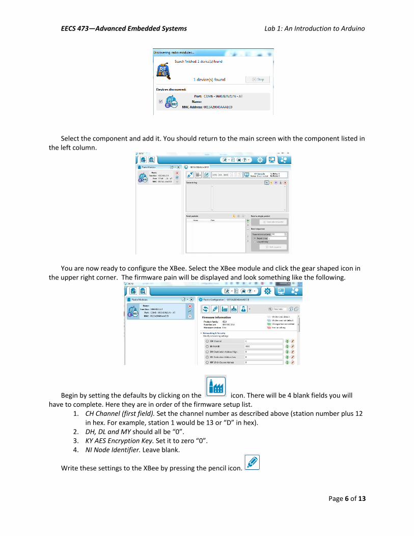
You are now ready to configure the XBee. Select the XBee module and click the gear shaped icon in
the upper right corner. The firmware pain will be displayed and look something like the following.
Begin by setting the defaults by clicking on the icon. There will be 4 blank fields you will have to complete. Here they are in order of the firmware setup list.
1. CH Channel (first field). Set the channel number as described above (station number plus 12 in hex. For example, station 1 would be 13 or “D” in hex).
2. DH, DL and MY should all be “0”. 3. KY AES Encryption Key. Set it to zero “0”. 4. NI Node Identifier. Leave blank.
Write these settings to the XBee by pressing the pencil icon.
EECS 473—Advanced Embedded Systems Lab 1: An Introduction to Arduino
Page 7 of 13
Remove the XBee and place it in the break out board so that you know it is programed. Be sure to match pin 1 of the XBee with pin 1 of the break out board or match the XBee board shape outline.
Put the remaining XBee in the Explorer board and repeat the configuration process (same channel
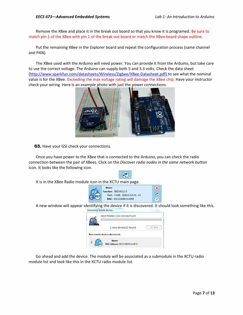
and PAN). The XBee used with the Arduino will need power. You can provide it from the Arduino, but take care
to use the correct voltage. The Arduino can supply both 5 and 3.3 volts. Check the data sheet (http://www.sparkfun.com/datasheets/Wireless/Zigbee/XBee-Datasheet.pdf) to see what the nominal value is for the XBee. Exceeding the max voltage rating will damage the XBee chip. Have your instructor check your wiring. Here is an example photo with just the power connections.
G3. Have your GSI check your connections.
Once you have power to the XBee that is connected to the Arduino, you can check the radio connection between the pair of XBees. Click on the Discover radio nodes in the same network button icon. It looks like the following icon.
It is in the XBee Radio module icon in the XCTU main page.
A new window will appear identifying the device if it is discovered. It should look something like this.
Go ahead and add the device. The module will be associated as a submodule in the XCTU radio
module list and look like this in the XCTU radio module list.
EECS 473—Advanced Embedded Systems Lab 1: An Introduction to Arduino
Page 8 of 13
You can check to see if you are sending serial data by sending a few characters with XCTU. Click on
the Console working mode icon on the main XCTU page. You will have to tell XCTU to connect the
console to the XBee plugged into the workstation. Click on the connect icon. Finally, add a few characters in the packet transmission window (use the plus button). Hit the send packet button and you should see something like this in the XCTU console window.
Verify the serial transmission by observing activity on the XBee serial output pin (see data sheet)
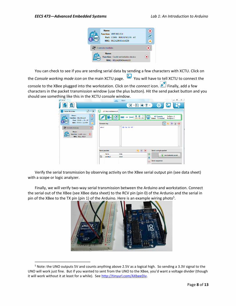
with a scope or logic analyzer. Finally, we will verify two-way serial transmission between the Arduino and workstation. Connect
the serial out of the XBee (see XBee data sheet) to the RCV pin (pin 0) of the Ardunio and the serial in pin of the XBee to the TX pin (pin 1) of the Arduino. Here is an example wiring photo5.
5 Note: the UNO outputs 5V and counts anything above 2.5V as a logical high. So sending a 3.3V signal to the
UNO will work just fine. But if you wanted to sent from the UNO to the XBee, you’d want a voltage divider (though it will work without it at least for a while). See http://tinyurl.com/AXbeeDiv.
EECS 473—Advanced Embedded Systems Lab 1: An Introduction to Arduino
Page 9 of 13
One fun issue is that you can’t program the board while the XBee is plugged into the Arduino. You will need to unplug the XBee’s serial connections (but not power and ground) when you program the
board. Be sure you put them back in the right way each time.
Q1. Why do you suppose the XBee needs to be unplugged each time? Write an Arduino program using the serial functions that echoes each character that is sent with an
“X” and a newline. So if you send “AB” you should get back “AX” and then “BX”. Send data via the XCTU program’s terminal from the XBee modem to your XBee/Arduino setup wirelessly. The XBee/Arduino should generate the response and sent it back over the wireless system.
Part 3—Wireless motor controller
On the lab page there is a “motor.txt” file. Disconnect the XBee serial connections, compile and upload this program, then reconnect the XBee. Go back to the X-CTU program and go to the Terminal Tab. Use the “Send Packets” interface to build and send packets. Look over the code to find a sequence of characters that results in the response “moving forward”. You may want to look at https://www.arduino.cc/en/Reference/Serial.
Q2. Examine the code. a. What sequence of characters results in the response “moving forward”? (There is an
explanation below that will help, but try to understand the code first.) b. Consider the packet xC21BE, where “x” is any arbitrary character. What will be the possible
outputs? Under what circumstance (what value of x) if any will it not be recognized as a legal reverse packet?
c. What pins are used to control which motor?
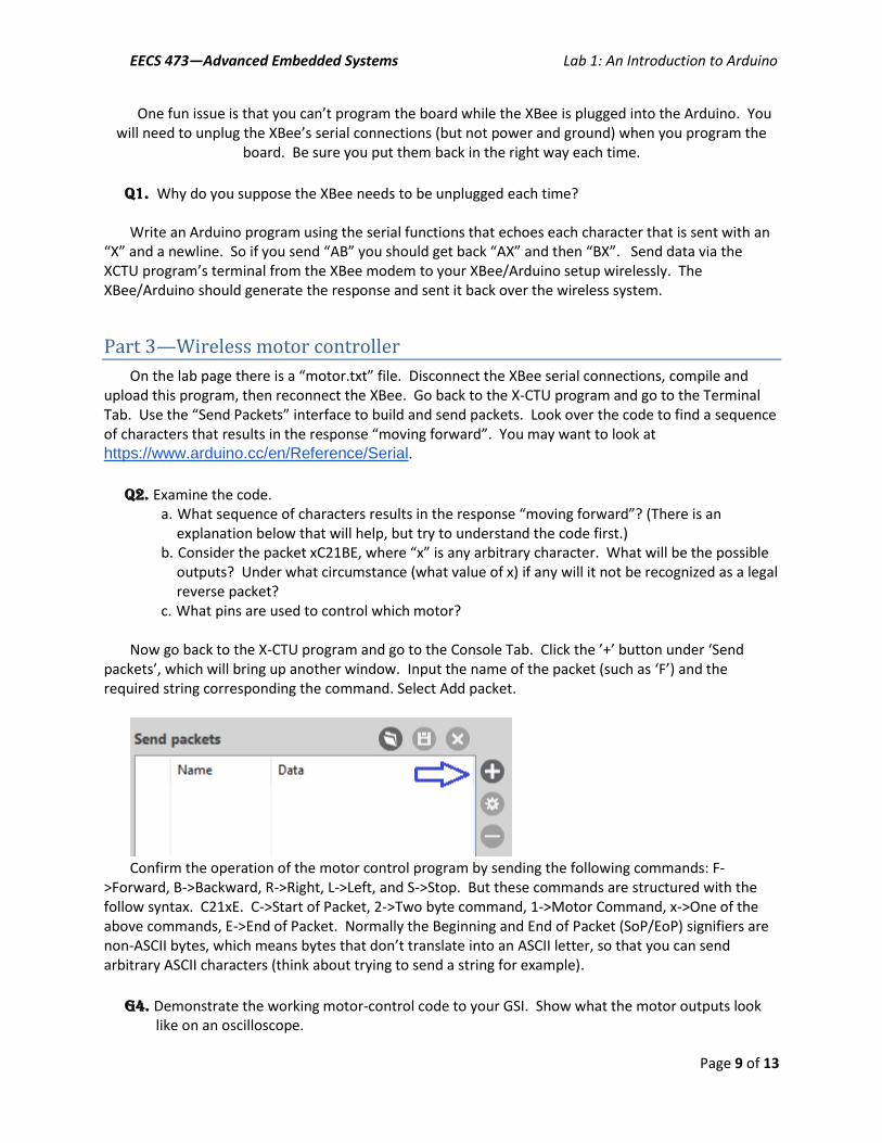
Now go back to the X-CTU program and go to the Console Tab. Click the ’+’ button under ‘Send packets’, which will bring up another window. Input the name of the packet (such as ‘F’) and the required string corresponding the command. Select Add packet.
Confirm the operation of the motor control program by sending the following commands: F-
>Forward, B->Backward, R->Right, L->Left, and S->Stop. But these commands are structured with the follow syntax. C21xE. C->Start of Packet, 2->Two byte command, 1->Motor Command, x->One of the above commands, E->End of Packet. Normally the Beginning and End of Packet (SoP/EoP) signifiers are non-ASCII bytes, which means bytes that don’t translate into an ASCII letter, so that you can send arbitrary ASCII characters (think about trying to send a string for example).
G4. Demonstrate the working motor-control code to your GSI. Show what the motor outputs look like on an oscilloscope.
EECS 473—Advanced Embedded Systems Lab 1: An Introduction to Arduino
Page 10 of 13
Q3. What does the output of pin 5 look like on the scope when it is at “SPEED”? Notice that it is labeled as an analog output in the code and as PWM on the board. Explain both labels.
Part 4—Self-guided H-bridge
In this class there we are often expecting you to be able to figure things out largely on your own. That said, we also want to be sure we don’t destroy our equipment. So we are asking you to wire everything up, but not to power your system until the GSI has looked over your setup.
We want you to use an H-bridge model # SN7544106 to drive a motor so that your wireless control system determines what direction the motor turns (or if it idles). Hook up the 5V output of the Arduino board as Vcc1 and use the power supply as Vcc2 with 6V output current limited to 200mA. Get a DC motor to turn in different directions depending on the signal sent. Modify the code so that the idle output state (where no outputs are enabled) can be reached.
NOTE: That on the banana plug to coaxial adapter the tab indicates the negative terminal.
G5. Demonstrate your working motor (complete with an idle option) to your GSI.
Part 5—Robot building time
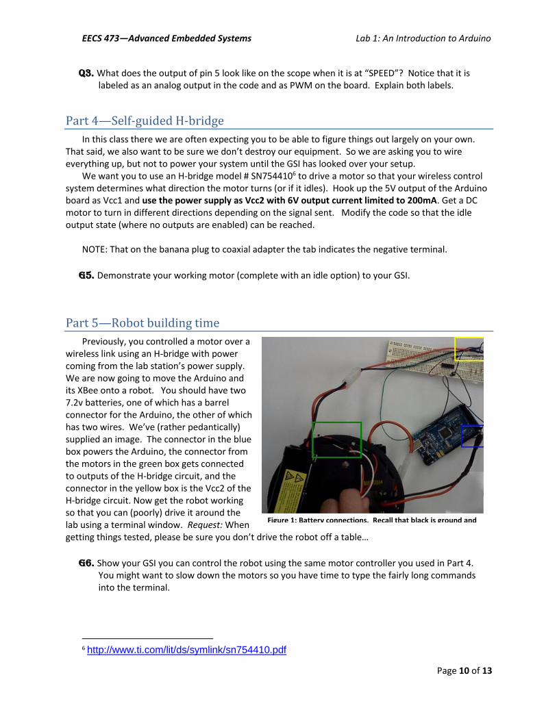
Previously, you controlled a motor over a wireless link using an H-bridge with power coming from the lab station’s power supply. We are now going to move the Arduino and its XBee onto a robot. You should have two 7.2v batteries, one of which has a barrel connector for the Arduino, the other of which has two wires. We’ve (rather pedantically) supplied an image. The connector in the blue box powers the Arduino, the connector from the motors in the green box gets connected to outputs of the H-bridge circuit, and the connector in the yellow box is the Vcc2 of the H-bridge circuit. Now get the robot working so that you can (poorly) drive it around the lab using a terminal window. Request: When getting things tested, please be sure you don’t drive the robot off a table…
G6. Show your GSI you can control the robot using the same motor controller you used in Part 4. You might want to slow down the motors so you have time to type the fairly long commands into the terminal.
6 http://www.ti.com/lit/ds/symlink/sn754410.pdf
Figure 1: Battery connections. Recall that black is ground and red is power.

EECS 473—Advanced Embedded Systems Lab 1: An Introduction to Arduino
Page 11 of 13
Request: when you leave the lab, please start recharging your batteries, especially the ones used to power the robot’s motors. In general we’d all like it if the batteries were generally in a charged state for the next folks in the lab. If you don’t know how to recharge the batteries, just ask.
EECS 473—Advanced Embedded Systems Lab 1: An Introduction to Arduino
Page 12 of 13
Part 6—Python control
import msvcrt
import serial
ser = serial.Serial('COM38', 9600)
while 1:
# Poll keyboard
if msvcrt.kbhit():
key = msvcrt.getch()
if key == 'f':
ser.write('C21FE')
elif key == 's':
ser.write('C21SE')
Now you are going to combine the Python code written above, and your robot. In the next lab, we
will extend this robot control interface substantially, but for now we just want a way to streamline sending commands.
G7. Show your GSI that your python script works and allows for basic control of your robot.
3. Post-lab
This post-lab has a few additional questions that generally require more thought and longer answers than the in-lab questions. Please submit the in-lab and post-lab questions as a single document. Both group members, working together, should do these together and submit just one document.
Wireless issues
Whenever we are working with wireless (radio) communication, sometimes it can be important to be aware of low-level details, including error correction/detection and bandwidth actually used. We may need to understand these things due to bandwidth limitations or concerns about noise. For noise, we are mainly worried about three things:
Our packet seeing interference from an external source and becoming corrupt.
Random (or not so random…) noise that the receiver perceives as a valid packet.
Random noise which happens before or after our packet causing our data to be lost or miscommunicated
Q4. Assume for now that our transmitter is just sending what we tell it to send. So if we send C21FE, only those characters (as ASCII characters) are sent out by the radio. a. Say the sender sends a legal motor control packet for the scheme you used in lab. Could a
single bit-flip (that is one bit of the message changing from a 0 to a 1 or a 1 to a 0) cause a different legal command (other than idle) to occur? If so, provide an example. If not, explain why not.
b. Say a random ASCII character is received right before your data. Rewrite the code so that all “xC21FE” packets will parse the code correctly, no matter the value of “x”. Submit a diff of your code and the original code (using the Linux/Unix “diff” ideally).
Q5. In reality, most communication schemes send a fair bit more data, often including a start delimiter and checksum. Look at the example found at
EECS 473—Advanced Embedded Systems Lab 1: An Introduction to Arduino
Page 13 of 13
https://web.archive.org/web/20140820153750/http://www.digi.com/support/kbase/kbaseresultdetl?id=2206. a. Why do you think there isn’t an End Delimiter? b. Calculate what the checksum would be for the example if the data packet were only 2 bytes:
0x0F and 0x1F. c. If you send 512 bytes one byte at a time, how many bytes (total) would need to be
transmitted? What if you sent all 512 at once? d. If you are streaming a massive amount of data using the same generic frames, what is the %
overhead of the protocol? (Think about what limits packet sizes.)
Arduino
Q6. Do a bit of research and explain the interrupt scheme used by the processor you are using. You may freely use web resources, but please cite your sources clearly. Your answer should include: a. How are different interrupts distinguished? b. How do you disable interrupts? c. How do you clear interrupts? d. Consider the sketch found at http://gonium.net/md/2006/12/20/handling-external-
interrupts-with-arduino/. Explain what is going on in your own words.
Q7. There are many advantages and disadvantages to using Arduino and its development environment. Where do you think you’d use it? Where are you fairly certain you wouldn’t use it?


![Electronics LAB [with Arduino] | DAY 3](https://img.pdfslide.net/doc/110x75/5552db86b4c90532498b4b46/electronics-lab-with-arduino-day-3-5584a0c28872d.jpg)


![Electronics LAB [with Arduino] | DAY 1](https://img.pdfslide.net/doc/110x75/5552db9ab4c90532498b4b51/electronics-lab-with-arduino-day-1-5584a0c27dcb9.jpg)