Embed Size (px)
Citation preview

Lab 12 Heat Engines and the First Law of Thermodynamics L12-1
Name Date Partners
Lab 12 - Heat Engines and the FirstLaw of Thermodynamics
“. . . the quantity of heat produced by the friction of bodies, whether solid orliquid, is always proportional to the quantity of energy expended.”
–James Joule
“The production of motion in a steam engine is always accompanied by a cir-cumstance which we should particularly notice. This circumstance is the passageof caloric from one body where the temperature is . . . elevated to another whereit is lower.”
–S.N.L. Carnot
OBJECTIVES
• To quantify the relationship between the heat energy transferred to a system and thechange in temperature of the system.
• To understand the meaning of specific heat and to measure its value.
• To understand phase changes as processes in which energy is transferred to or from asystem without the temperature changing, and to understand the concept of latent heat.
• To understand the energy balance of a system between heat energy transfer, work done,and changes in internal energy, as described by the first law of thermodynamics.
OVERVIEW
We understand that interactions take place when two substances in thermal contact are at differ-ent temperatures. We call these interactions “heat energy transfer.” There are other ways to raisethe temperature of an object. For example, by rubbing your hands together rapidly, you feel
University of Virginia Physics DepartmentPHYS 2030, Fall 2015
Modified from P. Laws, D. Sokoloff, R. ThorntonSupported by National Science Foundation
and the U.S. Dept. of Education (FIPSE), 1993-2000

L12-2 Lab 12 Heat Engines and the First Law of Thermodynamics
an increased temperature. Also, you probably have seen it is possible to produce a temperatureincrease using an electric heater by supplying electrical energy to it. Observations like thesecaused physicists and engineers in the middle of the nineteenth century to conclude that heat isjust a form of energy, the form that flows when there is a temperature difference between twoobjects.
We want to examine the mathematical relationship between the heat energy transferred to asystem and the temperature change of the system. In Investigation 2 you will look at the amountof heat energy transfer needed to raise the temperature of one unit of mass of water by onedegree, which is called the specific heat of the water.
The common unit of heat energy is the calorie. Mechanical energy is measured in joules, afamiliar unit used in your study of mechanics. The conversion factor between calories andjoules is commonly known as the mechanical equivalent of heat.
The nineteenth-century industrial revolution was based on the invention of heat engines. Heatengines have much in common with the chemical engines that power humans. For instance,both human engines and heat engines extract heat energy at a higher temperature, do work, andthen transfer waste heat energy to lower temperature surroundings. We will begin our studywith heat engines in Investigation 1, because of their great importance in understanding thelaws of thermodynamics. We shall see how we can place absolute limits on the efficiency ofheat engines. The steam engine, which ushered in the industrial revolution, and the internalcombustion engine both depend on cycles in which gases (the working medium of the engine)are alternately expanded and then compressed. The end result of these cycles is that a portionof heat energy transferred to a gas is converted into work. An understanding of the detailedphysics of the expansion and compression of gases has helped engineers to design more efficientengines.
Work is associated with a gas that expands or is compressed in a cylinder with a piston. Thisleads to the idea that the energy stored internally in a system can be increased by either transfer-ring heat energy to it or by doing work on it. The law that keeps track of the internal energy of asystem, the work done by the system, and heat energy transferred to the system is the first law ofthermodynamics. An understanding of this extended conservation of energy law is importantin practical endeavors, such as the design of heat engines.
In this lab we will examine a real heat engine that operates on expansions and compressionsof a gas, and attempt to determine the amount of work that it will produce on the basis ofour understanding of the physics of gas expansion and compression. Finally, we will calculatethe efficiency of this engine and compare it to the maximum possible efficiency for an engineoperating between the same temperatures.
In Investigation 3 you will consider how the transfer of heat energy can change a system in-ternally without changing its temperature. The process you will examine is the change of asubstance from solid to liquid or liquid to gas or vice versa, called a change of phase. You willmeasure the latent heat of vaporization of water–the amount of heat energy transfer required totransform one unit of mass of water from liquid to steam.
INVESTIGATION 1: Heat EnginesInternal combustion engines inside cars and trucks are examples of heat engines that burn agasoline—air mixture in the cylinders. The railroad steam engine, which spanned the Americancontinent in the mid-nineteenth century, is another example of a heat engine. The word “engine”conjures up an image of something that is started up, runs, and provides a continuous flow of
University of Virginia Physics DepartmentPHYS 2030, Fall 2015
Modified from P. Laws, D. Sokoloff, R. ThorntonSupported by National Science Foundation
and the U.S. Dept. of Education (FIPSE), 1993-2000

Lab 12 Heat Engines and the First Law of Thermodynamics L12-3
work. In the case of a car, the work done by the engine accelerates us until we reach a suitablespeed and then helps us maintain that speed by overcoming friction and air resistance.
The basic goal of any heat engine is to convert heat energy into work as efficiently as possible.This is done by taking a working medium–some substance that can expand and thus do workwhen heat energy is transferred to it–and placing it in a system designed to produce work incontinuous, repeated cycles.
An engine that is 100% efficient would have a working medium that transforms all of the heatenergy transferred to it to useful work. Such a process would not violate the first law of thermo-dynamics, since energy would be converted from one form to another, and conserved. However,no heat engine has ever been capable of transforming all of the heat energy transferred to it intouseful work. Some of the heat energy transferred in is always transferred back to the engine’ssurroundings at a lower temperature as waste heat energy. The universal existence of waste heatenergy has led scientists to formulate the second law of thermodynamics. A common statementof the second law is simply that it is impossible to transform all of the heat energy transferredto a system into useful work.
In this investigation you will explore the actual behavior of a simple heat engine. We can use anysubstance that changes its volume when heat energy is transferred to it as the working mediumfor a heat engine. The working medium is capable of transforming a fraction of the heat energytransferred into it to useful work. You will study the compression and expansion of gases usedas working substances in heat engines. As you complete this investigation, we hope you willbegin to understand that there are general principles that govern the operation of heat enginesthat do not depend on the detailed nature of the working medium.
Activity 1-1: Background Work Done by an Expanding Gas
ΔxΔV
A
P
A system we have already met in our study of thermodynamics is a massof gas confined in a syringe with a movable piston. The behavior of a gascompressed and expanding in a syringe is a simulation of what goes on inthe cylinders in a real engine like the internal combustion engine in yourcar, or, in fact, even more like a steam engine.
Prediction 1-1: (review) If a gas expands inside a cylinder with a movablepiston so that the volume changes by an amount ∆V while the pressure is keptconstant at a value p (isobaric process), what is the mathematical expressionto calculate the amount of work done by the gas?Do this before coming to lab.
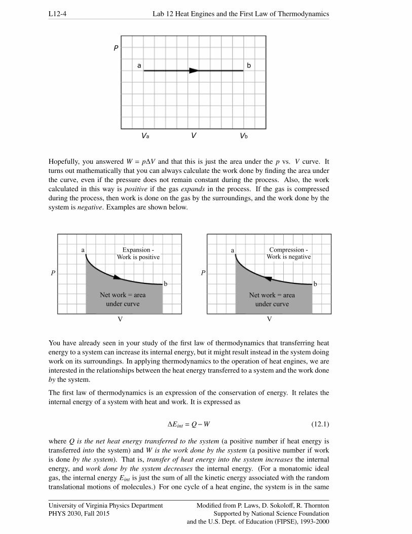
Prediction 1-2: (review) The graph that follows shows an isobaric expansion from avolume Va to a volume Vb represented on a p−V diagram. How can you find the workdone in the expansion from a to b from the graph? Do this before coming to lab.
University of Virginia Physics DepartmentPHYS 2030, Fall 2015
Modified from P. Laws, D. Sokoloff, R. ThorntonSupported by National Science Foundation
and the U.S. Dept. of Education (FIPSE), 1993-2000
L12-4 Lab 12 Heat Engines and the First Law of Thermodynamics
P
VVa Vb
a b
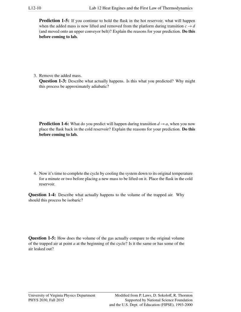
Hopefully, you answered W = p∆V and that this is just the area under the p vs. V curve. Itturns out mathematically that you can always calculate the work done by finding the area underthe curve, even if the pressure does not remain constant during the process. Also, the workcalculated in this way is positive if the gas expands in the process. If the gas is compressedduring the process, then work is done on the gas by the surroundings, and the work done by thesystem is negative. Examples are shown below.
P P
a a
b b
V V
Net work = areaunder curve
Net work = areaunder curve
Expansion -Work is positive
Compression -Work is negative
You have already seen in your study of the first law of thermodynamics that transferring heatenergy to a system can increase its internal energy, but it might result instead in the system doingwork on its surroundings. In applying thermodynamics to the operation of heat engines, we areinterested in the relationships between the heat energy transferred to a system and the work doneby the system.
The first law of thermodynamics is an expression of the conservation of energy. It relates theinternal energy of a system with heat and work. It is expressed as
∆Eint = Q−W (12.1)
where Q is the net heat energy transferred to the system (a positive number if heat energy istransferred into the system) and W is the work done by the system (a positive number if workis done by the system). That is, transfer of heat energy into the system increases the internalenergy, and work done by the system decreases the internal energy. (For a monatomic idealgas, the internal energy Eint is just the sum of all the kinetic energy associated with the randomtranslational motions of molecules.) For one cycle of a heat engine, the system is in the same
University of Virginia Physics DepartmentPHYS 2030, Fall 2015
Modified from P. Laws, D. Sokoloff, R. ThorntonSupported by National Science Foundation
and the U.S. Dept. of Education (FIPSE), 1993-2000

Lab 12 Heat Engines and the First Law of Thermodynamics L12-5
thermodynamic state that it was in at the start. In other words, all its properties, including itsinternal energy, are the same. For one complete cycle of a heat engine, ∆Eint = 0.
QH
QC
W
Heat energytransferredfrom hotreservoir(boiler orhair dryer)
Useful or network done onsurroundings
Waste heat energytransferred fromthe workingmedium to the lower temperaturereservoir orsurroundings
Workingmedium
If QH is the heat energy transferred to the system from thehot reservoir and QC is the heat energy transferred from thesystem to the cooler room air, the net heat energy transferredto the system in the cycle is Q = QH −QC and the first lawof thermodynamics becomes
∆Eint = Q−W = (QH −QC)−W (12.2)
Since ∆Eint = 0 for our complete cycle, we can simplify thisby writing
W = QH −QC (12.3)
This basic fact about heat engines is often discussed in termsof an energy flow diagram such as the one shown on theright. This diagram would work equally well for an old-fashioned steam engine or a simple heat engine we will use.
The figure on the right is a pictorial representation of whatwe have written in words: Our engine has heat energy QH
transferred to it, does heat engine schematic work W, andtransfers some of the original heat energy QC to the lowertemperature surroundings.
Activity 1-2: Background Finding Net Work Done in a Complete p-V Cycle
As we have seen, during parts of a cycle when a gas is expanding it is doing positive work on thesurroundings. When it is being compressed, work is being done on the gas by the surroundings,so the work done comes out negative.
Typically, at the completion of a heat engine cycle, the gas has the same internal energy, tem-perature, pressure, and volume that it started with. It is then ready to start another cycle. Duringvarious phases of the cycle, (12.1) heat energy transferred to the gas from the hot reservoir (e.g.,a boiler) causes the gas to do work on its surroundings as it expands, (12.2) the surroundings dowork on the gas to compress it, and (12.3) the gas transfers waste heat energy to the surroundingsor cold reservoir.
Real heat engines have linkages between a moving piston and the gas or other working medium,which allows the expansion and compression phases of the cycle to run automatically. Thus,some of the work done on the surroundings provides the work needed to compress the gas toreturn it to its starting point. The useful or net work done in an engine cycle must account forthe positive work done during expansion and the negative work done during compression.
Because the work done going from one state to another in one direction is positive and the workdone in the other direction is negative, it can be shown mathematically that the work done arounda closed loop on a p−V diagram, representing a complete cycle of the engine, is the same asthe area enclosed by the trace of the process on the diagram. This is illustrated below for twodifferent imaginary cycles.
University of Virginia Physics DepartmentPHYS 2030, Fall 2015
Modified from P. Laws, D. Sokoloff, R. ThorntonSupported by National Science Foundation
and the U.S. Dept. of Education (FIPSE), 1993-2000

L12-6 Lab 12 Heat Engines and the First Law of Thermodynamics
(a)
P P
(b)
V V
Net work =enclosed area
Net work =enclosed area
Point 1 Point 2
Point 3Point 4
In the next investigation, you will attempt to verify this relationship between useful work andthe area on a p−V diagram for a real engine.
Activity 1-3: Background The Incredible Mass-Lifting Heat Engine
m
y
Doing useful mechanicalwork by lifting a mass mthrough a height y.
O
Your working group has been approached by the Newton AppleCompany about testing a heat engine that lifts apples that varyin mass from 50 to 100 g from a processing conveyor belt to thepacking conveyor belt, which is 5 cm higher. The engine you areto experiment with is a “real” thermal engine that can be takenthrough a four-stage expansion and compression cycle and thatcan do useful mechanical work by lifting small masses from oneheight to another.
We would like you to verify experimentally that the useful me-chanical work done in lifting a mass m through a vertical distancey is equal to the net thermodynamic work done during a cycle asdetermined by finding the enclosed area on a p−V diagram. Es-sentially you are comparing useful mechanical mgy work withthe accounting of work in an engine cycle given by the area en-closed by the cycle.
Although you can prove mathematically that this relationshipholds, the experimental verification will allow you to become fa-
miliar with the operation of a real heat engine. In addition, it will be possible to calculate theheat energy transferred into the heat engine, and compare this to the useful work output.
P
V
a d
cb
Doing thermodynamicwork in a heat engine cycle
To carry out this experiment you will need
• 10 cc low-friction glass syringe with ring stand support
• flask (test tube) with one-hole rubber stopper
• a pressure sensor and a temperature sensor
• 2 – 400mL glass beakers
• several lengths of Tygon tubing
• paper towels
University of Virginia Physics DepartmentPHYS 2030, Fall 2015
Modified from P. Laws, D. Sokoloff, R. ThorntonSupported by National Science Foundation
and the U.S. Dept. of Education (FIPSE), 1993-2000

Lab 12 Heat Engines and the First Law of Thermodynamics L12-7
• ruler
• 50 g mass
• hot water (about 80-90◦C)
• ice water
The cylinder of the incredible mass-lifter engine is a low-friction glass syringe. The flat top ofthe handle of the piston serves as a platform for lifting masses. The flask and pressure sensorcan be connected to the syringe with short lengths of flexible Tygon tubing, and the flask can beplaced alternately in a cold reservoir and a hot reservoir. A schematic diagram of this mass lifterfollows.
Added mass
Syringe scale
Platform
Piston
Flask
Trapped airin syringe
Coldreservoir
Hotreservoir
Pressuresensor
If the temperature of the air trapped inside the cylinder, hose, and flask is increased, then itspressure will increase, causing the platform to rise. Thus, you can increase the volume of thetrapped air by moving the flask from the cold to the hot reservoir. Then when the mass has beenraised through a distance y, it can be removed from the platform. The platform should then risea bit more as the pressure on the cylinder of gas decreases a bit. Finally, the volume of the gaswill decrease when the flask is returned to the cold reservoir. This causes the piston to descendto its original position once again. The various stages of the mass lifter cycle are shown in thediagrams that follow.
University of Virginia Physics DepartmentPHYS 2030, Fall 2015
Modified from P. Laws, D. Sokoloff, R. ThorntonSupported by National Science Foundation
and the U.S. Dept. of Education (FIPSE), 1993-2000

L12-8 Lab 12 Heat Engines and the First Law of Thermodynamics
Point a Point b Point c Point d
Cold Cold Hot Hot
OO O
y y
The lifting and lowering parts of the cycle should be approximately isobaric, since the pressurein the air trapped in the syringe is determined by the weight of the piston (and the mass on top ofthe handle) pushing down on the gas. The other two parts of the cycle, when the mass is addedand removed from the piston handle, should be approximately adiabatic, because, as they occurvery quickly, there is not enough time for an appreciable amount of heat to flow into or out ofthe system.
Before taking data on the pressure, air volume, and height of lift with the heat engine, you shouldset it up and run it through a few cycles to get used to its operation. A good way to start is tofill one container with ice water and the other with hot tap water or preheated water at about80-90 ◦C.
The engine cycle is much easier to describe if you begin with the piston resting above the bottomof the syringe. Thus, we suggest you raise the piston so that the volume of air trapped inthe syringe is about 3-4 mL before inserting the rubber stopper firmly in the flask. Also,air does leak out of the syringe slowly. If a large mass is being lifted, the leakage rate increases,so we suggest that you limit the added mass to 50 g.
IMPORTANT: As you take the engine through its cycle, observe whether the piston ismoving freely in the syringe. If it is sticking, use a paper towel to clean the piston. Youmay need to do this 3 or 4 times to free up the piston. It may be a good idea to do thisas a precaution. If it continues to stick, ask you TA for help.
After observing a few engine cycles, you should be able to describe each of the points a, b, c,and d of a cycle, carefully indicating which of the transitions between points are approximatelyadiabatic and which are isobaric.
You should reflect on your observations by answering the questions in the next activity. You canobserve changes in the volume of the gas directly and you can predict how the pressure exertedon the gas by its surroundings ought to change from point to point by using the definition ofpressure as force per unit area.
University of Virginia Physics DepartmentPHYS 2030, Fall 2015
Modified from P. Laws, D. Sokoloff, R. ThorntonSupported by National Science Foundation
and the U.S. Dept. of Education (FIPSE), 1993-2000

Lab 12 Heat Engines and the First Law of Thermodynamics L12-9
Activity 1-4: Description of the Engine Cycle
Prediction 1-3: With the system closed to the outside air and the flask in the coldreservoir, what should happen to the height of the platform during transition a→ b, as youadd the mass to the platform? Explain the basis of your prediction. Do this before comingto lab.
1. Make sure the piston moves easily in the syringe. Make sure the rubber stopper is firmlyin place in the tube. Make sure that you start with the piston with about 3-4 mL of gas inthe cylinder. Add the mass to the platform.Question 1-1: Describe what happened. Is this what you predicted? Why might thisprocess be approximately adiabatic?
Prediction 1-4: What do you expect to happen during transition b→c, when you placethe flask in the hot reservoir? Do this before coming to lab.
2. Place the flask in the hot reservoir. (This is the engine power stroke!)Question 1-2: Describe what happens. Is this what you predicted? Why should thisprocess be isobaric?
University of Virginia Physics DepartmentPHYS 2030, Fall 2015
Modified from P. Laws, D. Sokoloff, R. ThorntonSupported by National Science Foundation
and the U.S. Dept. of Education (FIPSE), 1993-2000
L12-10 Lab 12 Heat Engines and the First Law of Thermodynamics
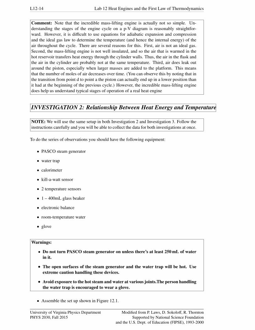
Prediction 1-5: If you continue to hold the flask in the hot reservoir, what will happenwhen the added mass is now lifted and removed from the platform during transition c→ d(and moved onto an upper conveyor belt)? Explain the reasons for your prediction. Do thisbefore coming to lab.
3. Remove the added mass.Question 1-3: Describe what actually happens. Is this what you predicted? Why mightthis process be approximately adiabatic?
Prediction 1-6: What do you predict will happen during transition d→ a, when you nowplace the flask back in the cold reservoir? Explain the reasons for your prediction. Do thisbefore coming to lab.
4. Now it’s time to complete the cycle by cooling the system down to its original temperaturefor a minute or two before placing a new mass to be lifted on it. Place the flask in the coldreservoir.
Question 1-4: Describe what actually happens to the volume of the trapped air. Whyshould this process be isobaric?
Question 1-5: How does the volume of the gas actually compare to the original volumeof the trapped air at point a at the beginning of the cycle? Is it the same or has some of theair leaked out?
University of Virginia Physics DepartmentPHYS 2030, Fall 2015
Modified from P. Laws, D. Sokoloff, R. ThorntonSupported by National Science Foundation
and the U.S. Dept. of Education (FIPSE), 1993-2000

Lab 12 Heat Engines and the First Law of Thermodynamics L12-11
Question 1-6: Theoretically, the pressure of the gas should be the same once you coolthe system back to its original temperature. Why?
To calculate the thermodynamic work done during a cycle of this engine you will need to be ableto plot a p vs. V diagram for the engine based on determinations of the volumes and pressuresof the trapped air in the cylinder, Tygon tubing, and flask at the points a, b, c, and din the cycle.
Activity 1-5: Work Done by the Heat Engine
1. We have estimated the total volume of the tube, tubing, and pressure sensor and enteredthis into Table 12.1.
2. Connect the pressure sensor and temperature sensor to the interface and start up the soft-ware.
3. Open the experiment file called L12.A1-2 Pressure and Temperature. This will set upthe software in prompted event mode so that you can continuously measure pressure anddecide when you want to keep a value. Then you can enter the measured volume.
State of system Volume of air in syringe (cm3)a
b
c
d
a’
Table 12.1: Volume Determination
Now you should be able to take your engine through another cycle and make the measure-ments of volume and pressure of the air needed to determine the p−V diagram for yourheat engine. You should take your data rapidly to minimize air leakage around the piston.
4. Begin with the test tube and temperature sensor in the ice water, and without the mass onthe piston platform of the syringe (state a). A volume of 3-4 ml (cm3) is about right tostart with. Stir the ice water. Start taking data. When the temperature and pressure seemto be fairly stable, keep those data values (press Keep).
5. Read the volume of air in the syringe, enter it in Table 12.1 and enter this value into thecomputer.
6. Quickly place the mass on top of the handle of the syringe (state b).
7. When the temperature and pressure seem to be fairly stable, keep those data values (press Keep again). Again, record the volume of air in the syringe in Table 12.1 and enterthis value into the computer.
University of Virginia Physics DepartmentPHYS 2030, Fall 2015
Modified from P. Laws, D. Sokoloff, R. ThorntonSupported by National Science Foundation
and the U.S. Dept. of Education (FIPSE), 1993-2000

L12-12 Lab 12 Heat Engines and the First Law of Thermodynamics
8. Quickly move the flask and temperature sensor to the hot water reservoir (state c). Whenthe temperature and pressure seem to be fairly stable, keep those data values. Again,record the volume of air in the syringe in Table 12.1 and enter this value into the com-puter.
9. Quickly remove the mass (state d). When the temperature and pressure seem to be fairlystable, keep those data values. Again, record the volume of air in the syringe in Ta-ble 12.1 and enter this value into the computer.
10. Finally, move the flask and temperature sensor back to the ice-water reservoir (state a′).Stir the ice water. When the temperature and pressure seem to be fairly stable, keep thosedata values. Again, record the volume of air in the syringe in the table and enter thisvalue into the computer.
11. Determine the height that the mass was raised during the power stroke (b→ c). This canbe determined by dividing the volume change from b→ c by the piston area. Show yourcalculation and record the height below. The diameter of the piston is 14.66 mm.
Height mass was raised from b→ c : cm
Amount of mass lifted: g
12. Print the graph and the data table.
Question 1-7: You expected that the transitions from b → c and from d → a′ wereisobaric. According to your data, were they? Explain.
Activity 1-6: Calculating the Work Done by the Heat Engine
Recall that the thermodynamic work done by the heat engine is the sum of the work done in eachof the cycle’s segments1:
Wnet =Wa→b+Wb→c+Wc→d +Wd→a′ +Wa′→a (12.4)
You can approximate the work done in each part of the cycle (a→b, b→c, etc.) as being theaverage pressure times the change in volume. For example, for the a→b part of the cycle, thework is given by:
1 Note that we have to “close the loop” by adding the a→ a′ segment.
University of Virginia Physics DepartmentPHYS 2030, Fall 2015
Modified from P. Laws, D. Sokoloff, R. ThorntonSupported by National Science Foundation
and the U.S. Dept. of Education (FIPSE), 1993-2000

Lab 12 Heat Engines and the First Law of Thermodynamics L12-13
Wa→b =
∫ b
apdV ≈ p̄∆V =
( pa+ pb
2
)(Vb−Va) (12.5)
Note the result of such an approximation is to treat the transition between two states as a straightline on the p−V diagram.
Question 1-8: While collecting the data and claculating the work done by the enginewhy do we not have to worry about the volume of the air in the flask and have it added tothe total volume of air?
Prediction 1-7: Using above approximation describe qualitatively how you will find thenet thermodynamic work done by heat engine.
Prediction 1-8: Calculate the net thermodynamic work done by heat engine. You mayfind using the ”Area” tool of the software very helpful.
Wthermodynamic : mJ
Prediction 1-9: Use the equation Wuseful = mgy to calculate the useful mechanical workdone in lifting the mass from one level to the other in joules (J). You determined the heighty for the power stroke in the previous activity. Show your work here.
Wuseful : mJ
Question 1-9: How does the thermodynamic work (cycle) compare to the usefulmechanical work from b→ c (when the apple is raised)? Please use the correct number ofsignificant figures in your comparison (as you have been doing all along, right?)
University of Virginia Physics DepartmentPHYS 2030, Fall 2015
Modified from P. Laws, D. Sokoloff, R. ThorntonSupported by National Science Foundation
and the U.S. Dept. of Education (FIPSE), 1993-2000
L12-14 Lab 12 Heat Engines and the First Law of Thermodynamics
Comment: Note that the incredible mass-lifting engine is actually not so simple. Un-derstanding the stages of the engine cycle on a p-V diagram is reasonably straightfor-ward. However, it is difficult to use equations for adiabatic expansion and compressionand the ideal gas law to determine the temperature (and hence the internal energy) of theair throughout the cycle. There are several reasons for this. First, air is not an ideal gas.Second, the mass-lifting engine is not well insulated, and so the air that is warmed in thehot reservoir transfers heat energy through the cylinder walls. Thus, the air in the flask andthe air in the cylinder are probably not at the same temperature. Third, air does leak outaround the piston, especially when larger masses are added to the platform. This meansthat the number of moles of air decreases over time. (You can observe this by noting that inthe transition from point d to point a the piston can actually end up in a lower position thanit had at the beginning of the previous cycle.) However, the incredible mass-lifting enginedoes help us understand typical stages of operation of a real heat engine
INVESTIGATION 2: Relationship Between Heat Energy and Temperature
NOTE: We will use the same setup in both Investigation 2 and Investigation 3. Follow theinstructions carefully and you will be able to collect the data for both investigations at once.
To do the series of observations you should have the following equipment:
• PASCO steam generator
• water trap
• calorimeter
• kill-a-watt sensor
• 2 temperature sensors
• 1 – 400mL glass beaker
• electronic balance
• room-temperature water
• glove
Warnings:
• Do not turn PASCO steam generator on unless there’s at least 250 mL of waterin it.
• The open surfaces of the steam generator and the water trap will be hot. Useextreme caution handling these devices.
• Avoid exposure to the hot steam and water at various joints.The person handlingthe water trap is encouraged to wear a glove.
• Assemble the set up shown in Figure 12.1.
University of Virginia Physics DepartmentPHYS 2030, Fall 2015
Modified from P. Laws, D. Sokoloff, R. ThorntonSupported by National Science Foundation
and the U.S. Dept. of Education (FIPSE), 1993-2000
Lab 12 Heat Engines and the First Law of Thermodynamics L12-15
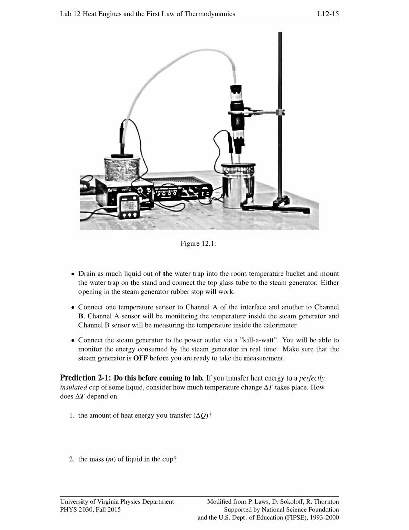
Figure 12.1:
• Drain as much liquid out of the water trap into the room temperature bucket and mountthe water trap on the stand and connect the top glass tube to the steam generator. Eitheropening in the steam generator rubber stop will work.
• Connect one temperature sensor to Channel A of the interface and another to ChannelB. Channel A sensor will be monitoring the temperature inside the steam generator andChannel B sensor will be measuring the temperature inside the calorimeter.
• Connect the steam generator to the power outlet via a ”kill-a-watt”. You will be able tomonitor the energy consumed by the steam generator in real time. Make sure that thesteam generator is OFF before you are ready to take the measurement.
Prediction 2-1: Do this before coming to lab. If you transfer heat energy to a perfectlyinsulated cup of some liquid, consider how much temperature change ∆T takes place. Howdoes ∆T depend on
1. the amount of heat energy you transfer (∆Q)?
2. the mass (m) of liquid in the cup?
University of Virginia Physics DepartmentPHYS 2030, Fall 2015
Modified from P. Laws, D. Sokoloff, R. ThorntonSupported by National Science Foundation
and the U.S. Dept. of Education (FIPSE), 1993-2000

L12-16 Lab 12 Heat Engines and the First Law of Thermodynamics
In this investigation you will conduct a series of observations in which you examine quantita-tively the relationship between ∆T and these other variables.
Activity 2-1: Transferring Different Amounts of Heat Energy to the Same Mass ofWater
1. Open the experiment file called L12.A2-1 Heating and Boiling Water.
2. Weigh the empty beaker and write down its mass:
Mass of the beaker g
3. Weigh the empty calorimeter with the outer cover and the lid and write down its mass:
Total mass of the calorimeter, mcalo g
4. Fill the steam generator with about 500-550 g (mL) or room temperature water. Carefullyweigh the water before putting it in and enter the mass of the water (subtract mass ofcup/beaker) below. Make sure that there is no additional water left in the generator byprevious groups.
Mass of water in the steam generator, m: g
5. Fill the calorimeter cup to 2/3 with room temperature water. The amount of water will beabout 130 g (mL). Measure the amount of water together with the calorimeter and thecover carefully and record it below. Do not fill the calorimeter cup all the way to thetop. Leave at least 1/3 of the height of the cup empty.
Mass of water, calorimeter and the cover before, m1: g
6. Insert temperature sensor A into the steam generator (feed it through the tube in the rubberstop) and sensor B into the calorimeter (calorimeter lid has a small hole for the sensor).
7. Slowly lower the water trap into the calorimeter. Make sure that the lower glass tube issubmerged into the water. Double check all of the connection and confirm that all rubberstops and hoses are fitted firmly.
8. Start the data collection and begin graphing. One graph will show the water temper-ature in the steam generator and another the water temperature in the calorimeter. Forthe first 10 s, leave the steam generator OFF. Dial the heating power knob on the steamgenerator to High and turn it ON.
9. After the temperature in the steam generator starts increasing note the reading of the con-sumed power on the ”kill-a-watt” and write it below. Note that the power will changeslightly as the water heats up but should be stable within 1% in the temperature rangebetween 25 and 50◦C.
Steam generator wattage between 30 and 50◦C, P: W
10. Keep the data on the graph. Do not erase it. We will use all parts of the graphs in the lateranalysis. Continue heating the water up until it boils and the steam is produced. You willclearly see the silicon tubing and the water trap fog up. At this point, if have not already,make sure that the bottom glass tube of the water trap is submerged into the water in thecalorimeter.
University of Virginia Physics DepartmentPHYS 2030, Fall 2015
Modified from P. Laws, D. Sokoloff, R. ThorntonSupported by National Science Foundation
and the U.S. Dept. of Education (FIPSE), 1993-2000

Lab 12 Heat Engines and the First Law of Thermodynamics L12-17
11. After few moments you will see that the the water temperature in the calorimeter increasesquite rapidly from its original value t1. Continue to boil water until the temperature in thecalorimeter reaches about 90-95◦C. Watch it carefully not to exceed the water boilingtemperature. Once the temperature approaches 90-95◦C turn the steam generator OFF,SLOWLY and CAREFULLY pull the water trap (not the temperature probe) from thecalorimeter and CAREFULLY stir the water in the calorimeter by swirling it. You willsee the calorimeter temperature levels off. Record the mixture temperature (t2) for fewseconds and Stop the Capstone. Again measure the amount of water together with thecalorimeter and the cover carefully and record it below.
Mass of water, calorimeter and the cover after, m2: g
12. You now have all the data for this experiment. To make the data analysis in this lab fasterwe have prepared an Excel file L12.Heat Energy and Temperature.xls for you. Openthe file and type all of the data collected so for in it.
Question 2-1: Describe the shape of your graph. What does this say about the relation-ship between the temperature change and the quantity of heat energy transferred to thewater? (Remember that heat was transferred at a constant rate.)
Question 2-2: Suppose you transfer heat energy for the same time to a larger mass ofwater, say 1000 g.
1. How will the temperature change?
2. You heated about 500 g of water with the heater on for 40 s. How long do you think theheater will need to be on to produce the same temperature increase if you heat twice asmuch water (about 1000 g)?
Time: s
Question 2-3: Based on your graphs and data, discuss the following mathematical rela-tionship:
∆Q = cm∆T (12.6)
∆Q is the heat energy transferred to the water, m is the mass of the water, ∆T is the changein temperature, and c is a constant characteristic of the liquid.
University of Virginia Physics DepartmentPHYS 2030, Fall 2015
Modified from P. Laws, D. Sokoloff, R. ThorntonSupported by National Science Foundation
and the U.S. Dept. of Education (FIPSE), 1993-2000
L12-18 Lab 12 Heat Engines and the First Law of Thermodynamics
You have examined the relationship between the amount of heat energy transferred to a systemand the system’s change in temperature. If we had more time and could do more experiments,you would see that the change in temperature is proportional to the amount of heat energytransferred and inversely proportional to the mass of the system. To be more quantitative (e.g.,to be able to predict numerical temperature changes), it is necessary to specify what amount ofheat energy transfer will produce a one degree change in temperature in unit mass of a material.This quantity is known as the specific heat of the material. It is the value c in the equation inQuestion 2-3.
specific heat = c =∆Q
m∆T(12.7)
The standard units for heat energy (J), mass (kg), and temperature (◦C), give us the unit forspecific heat, J/kg·◦C. In the next activity you will calculate the specific heat of water from yourdata.
Activity 2-2: Specific Heat of Water
We can use data that you obtained in the previous Activity to determine the specific heat of water.Let’s re-write Eq. (12.7) slightly. Recall that 1 W = 1 J/s, i.e., the amount of transferred energyis the power consumed by the steam generator (P) multiplied by the time the steam generatorwas on (∆t), so that Q = P∆t
c =∆Q
m∆T=
P
m∆T∆t
=P
m slope(12.8)
since the relation between the water temperature in the steam generator and time is linear thequantity ∆T
∆t is the slope of the T vs. t graph.
On the graph of steam generator water temperature vs. time select a region of constant slope asclose to the room temperature as possible (temperature range of 30 to 50◦C works the best) andfit it with the linear fit to extract the slope.
slope: ◦C/s
Question 2-4: Calculate the heat capacitance of water. Show your calculations below.
cwater: J/g·◦C
Question 2-5: How did your value agree with the accepted value of 4.19 J/g·◦C? Whatare the possible sources of experimental error that might explain any disagreement?
University of Virginia Physics DepartmentPHYS 2030, Fall 2015
Modified from P. Laws, D. Sokoloff, R. ThorntonSupported by National Science Foundation
and the U.S. Dept. of Education (FIPSE), 1993-2000

Lab 12 Heat Engines and the First Law of Thermodynamics L12-19
Question 2-6: How many seconds would it take the heater to raise the temperature of500 g of water by 25◦C? (Use the accepted value for cwater.)
INVESTIGATION 3: Change of Phase from Gas to Liquid
Prediction 3-1: Do this before coming to lab. On the axes that follow, sketch a graph oftemperature vs. time for a cup of water initially at 20◦C that is heated in the following way:
1. Heat energy is transferred at a constant rate until the water reaches its boiling-point tem-perature. (Assume that this happens in the first 6 min.)
2. Heat energy is then transferred at the same constant rate as the water boils for the next4 min.
Time (min)
Tem
pera
ture
(°C
)
20
100
0 2 4 6 8 10
Activity 3-1: Heating Water to Its Boiling Point: A Temperature History
1. We have already performed the experiment in the previous Activity. You will continueexamining the graph of water temperature in the steam generator vs. time.
2. Print the graph if you have not already and indicate with an arrow where the water beganboiling vigorously.
Question 3-1: Does your graph agree with the prediction you made? If not, describe theways in which the observed behavior of boiling water was different from your prediction.
University of Virginia Physics DepartmentPHYS 2030, Fall 2015
Modified from P. Laws, D. Sokoloff, R. ThorntonSupported by National Science Foundation
and the U.S. Dept. of Education (FIPSE), 1993-2000

L12-20 Lab 12 Heat Engines and the First Law of Thermodynamics
Question 3-2: During the time that the temperature remained constant, what do you thinkhappened to the heat energy you were transferring if it wasn’t raising the temperature?
Comment: Most substances can exist in three states–solid, liquid, and gas. As you haveseen, these changes of state or phase changes usually involve a transfer of heat energy. Dur-ing a phase change, the substance can absorb heat energy without changing its temperatureuntil the phase change is complete. The transferred energy increases the internal energy ofthe system.
The amount of heat energy transfer required to transform one kilogram of water at its boilingpoint into steam is called the latent heat of vaporization. (This amount of energy is the same asthe amount transferred away from one kilogram of steam when it condenses.)
Activity 3-2: Latent Heat of Vaporization of Water
Let’s re-examine the experiment in the earlier Activity. We used the steam generator to heat aknown amount of water in the generator with a known amount of energy to examine the relationbetween the energy, temperature change and the mass of the water. Later on we boiled someamount of water out thus converting it into steam. We piped the steam into a calorimeter andmixed it with the water at different temperature. As a result the steam condenses into the waterand the vaporization heat is transferred to the calorimeter water. You saw that the steam warmscold water up to the mixing temperature t2. At the same time the water produced from the steamis cooled down to the mixing temperature t2. If we assume that the steam is produced at 100◦Cwe can write the energy balance equation for our system.
The energy delivered to the system consists of two parts: the vaporization heat ”locked” inthe steam which is released during the phase transition (Q1) and the amount of the heat in thecondensed water which is cooled from the phase transition temperature of 100◦C to the mixturetemperature (Q2).
Q+ = Q1+Q2 = msteam · cv+ cwater ·msteam · (100◦C− t2) (12.9)
where msteam is the mass of the condensed steam, cv is the latent heat of vaporization (conden-sation) of water we are after, and cwater is already familiar heat capacitance of water measuredearlier.
The energy consumed by the the system is the amount of energy to warm the calorimeter waterfrom the room temperature t1 to the mixture temperature t2.
Q− = cwater ·mwater · (t2− t1) (12.10)
where mwater is the amount of water originally in the calorimeter cup.
Equating the delivered and consumed energies in the closed system we can solve for the latentheat of vaporization as follows:
Q+ = Q−
msteam · cv+ cwater ·msteam · (100◦C− t2) = cwater ·mwater · (t2− t1)
University of Virginia Physics DepartmentPHYS 2030, Fall 2015
Modified from P. Laws, D. Sokoloff, R. ThorntonSupported by National Science Foundation
and the U.S. Dept. of Education (FIPSE), 1993-2000
Lab 12 Heat Engines and the First Law of Thermodynamics L12-21
cv =cwater
msteam· {mwater · (t2− t1)−msteam · (100◦C− t2)} (12.11)
1. Using Capstone Smart Tool measure the calorimeter water initial temperature and themixture final temperature from the graph of the calorimeter water temperature vs. time.
t1: ◦C t2: ◦C
2. From the values of the total calorimeter mass before (m1) and after (m2) calculate theamount of steam condensed in the calorimeter.
msteam = m2−m1: g
3. From the value of the mass of the empty calorimeter mcalo and calorimeter filled withwater calculate the initial mass of water in the calorimeter.
mwater = m1−mcalo: g
4. Calculate the latent heat of vaporization of the water using Eq. (12.11). Show your calcu-lations.
Latent heat of vaporization cv: J/g
Question 3-3: Compare your value for the latent heat of vaporization to the acceptedvalue, 2.26 x 10³ J/g. Discuss the limitations in the experimental method you used thatmight account for any differences between these two values.
Question 3-4: In your current set-up can you think of an additional measurement(s) thatmay yield an alternative method of measuring the latent heat of vaporization of water?
Question 3-5: Compare the heat energy needed to convert one kilogram of water tosteam to that needed to convert one kilogram of ice to water (334 J/g). Why do you thinkthat one is much larger than the other?
Please clean up your lab area!University of Virginia Physics DepartmentPHYS 2030, Fall 2015
Modified from P. Laws, D. Sokoloff, R. ThorntonSupported by National Science Foundation
and the U.S. Dept. of Education (FIPSE), 1993-2000