Embed Size (px)
Citation preview

SOFTWARE DEFINED NETWORKING
Lab 6: Introduction to OpenFlow
Document Version: 05-28-2020
Award 1829698 “CyberTraining CIP: Cyberinfrastructure Expertise on High-throughput
Networks for Big Science Data Transfers”

Lab 6: Introduction to OpenFlow
Page 2
Contents Overview ............................................................................................................................. 3
Objectives............................................................................................................................ 3
Lab settings ......................................................................................................................... 3
Lab roadmap ....................................................................................................................... 3
1 Introduction ................................................................................................................ 3
1.1 Data, control and management planes ................................................................ 3
1.2 OpenFlow Overview ............................................................................................. 5
1.3 OpenFlow components ........................................................................................ 6
2 Lab topology................................................................................................................ 7
2.1 Lab settings........................................................................................................... 8
2.2 Loading a topology ............................................................................................... 8
3 Monitoring and administering OpenFlow switches .................................................. 10
4 Capturing OpenFlow packets .................................................................................... 14
4.1 Starting Wireshark .............................................................................................. 14
4.2 Starting ONOS controller .................................................................................... 17
4.3 Capturing PACKET_IN and PACKET_OUT messages ........................................... 20
References ........................................................................................................................ 22
Lab 6: Introduction to OpenFlow
Page 3
Overview This lab is an introduction to OpenFlow, which defines both the communications protocol between the Software Defined Networking (SDN) data plane and the SDN control plane, and part of the behavior of the data plane. In this lab, you will use the ovs-ofctl command line utility to administer OpenFlow switches, such as inserting/deleting flows. The focus in this lab is to understand and inspect the OpenFlow messages exchanged between the control plane and the data plane. Objectives By the end of this lab, the user will:
1. Understand SDN and its components. 2. Understand OpenFlow. 3. Configure OpenFlow switches using ovs-ofctl. 4. Configure ONOS controller 5. Use Wireshark network analyzer to capture OpenFlow packets.
Lab settings The information in Table 1 provides the credentials to access the Client’s virtual machine.
Table 1. Credentials to access Client’s virtual machine.
Device
Account
Password
Client admin password
Lab roadmap This lab is organized as follows:
1. Section 1: Introduction. 2. Section 2: Lab topology. 3. Section 3: Monitoring and administering OpenFlow switches. 4. Section 4: Capturing OpenFlow packets.
1 Introduction 1.1 Data, control and management planes

Lab 6: Introduction to OpenFlow
Page 4
The various switching functions are traditionally segregated into three separate categories. Since each category may be capable of horizontal communication with peer elements in adjacent entities in a topology, and also capable of vertical communication with the other categories, it has become common to represent each of these categories as a layer or plane. Peer communication occurs in the same plane, and cross-category messaging occurs in the third dimension, between planes3. Consider Figure 1. The vast majority of packets handled by the switch are only managed by the data plane. The data plane consists of the various ports that are used for the reception and transmission of packets and a forwarding table with its associated logic. The data plane assumes responsibility for packet buffering, packet scheduling, header modification, and forwarding. If an arriving data packet’s header information is found in the forwarding table, it may be subject to some header field modification and then will be forwarded without any intervention of the other two planes3. Not all packets can be handled in that way, sometimes simply because their information is not yet entered into the table, or because they belong to a control protocol that must be processed by the control plane. The control plane, (see Figure 1), is involved in many activities. Its principal role is to keep current the information in the forwarding table so that the data plane can independently handle as high a percentage of the traffic as possible. The control plane is responsible for processing a number of different control protocols that may affect the forwarding table, depending on the configuration and type of switch. These control protocols are jointly responsible for managing the active topology of the network3. The third plane depicted in Figure 1 is the management plane. Network administrators configure and monitor the switch through this plane, which in turn extracts information from or modifies data in the control and data plane as appropriate. The network administrators use some form of network management system to communicate with management plane in a switch3.

Lab 6: Introduction to OpenFlow
Page 5
Management Plane
Control plane
Data plane
Forwarding TableData in Data out
Unknown packets control packets
Update forwarding table
Policies
ConfigurationStatistics, Status
Simple Network Management Protocol
Figure 1. Roles of the control, data and management planes3.
1.2 OpenFlow Overview
OpenFlow defines both the communication protocol between the SDN data plane and the SDN control plane, as well as part of the behavior of the data plane. It does not describe the behavior of the controller itself. There are other approaches to SDN, but today OpenFlow is the only nonproprietary, general-purpose protocol for programming the forwarding plane of SDN switches3. Consider Figure 2. In a basic component of OpenFlow system, there is always an OpenFlow controller that communicates to one or more OpenFlow switches. The OpenFlow protocol defines the specific messages and message formats exchanged between the controller (control plane) and the device (data plane). The OpenFlow behavior specifies how the device should react in various situations and how it should respond to commands from the controller.

Lab 6: Introduction to OpenFlow
Page 6
s1
c0
s2 s3 s5s4
Figure 2. OpenFlow components.
1.3 OpenFlow components
In a packet switch, the core function is to take packets that arrive on one port and forward them through another port. OpenFlow switches perform this operation using the packet-matching function with the flow table. Thus, once a packet arrives to the switch, the latter will look up in its flow table and check if there is a match. Consequently, the switch will decide which action to take based on the flow table. The action could be:
• Forward the packet out a local port
• Drop the packet
• Pass the packet to the controller.
The basic functions of an OpenFlow switch and its relationship to a controller is depicted in Figure 3. When the data plane doesn’t have a match to the incoming packet, it sends a PACKET_IN message to the controller. The control plane runs routing and switching protocols and other logic to determine what the forwarding tables and logic in the data plane should be. Consequently, when the controller has a data packet to forward out through the switch, it uses the OpenFlow PACKET_OUT message. All the communication between OpenFlow controller and data plane are defined by the OpenFlow protocol.

Lab 6: Introduction to OpenFlow
Page 7
OpenFlow controller
Flow table
PACKET_IN PACKET_OUT
Port 1 Port 2 Port 3 Port 4 Port 5 Port 6
OpenFlow switch
Packet-matchingfunction
OpenFlow Protocol
Figure 3. OpenFlow switch.
2 Lab topology Consider Figure 4. The topology consists of two end-hosts, a switch and a controller. The blue device is an OpenFlow switch and it is directly connected to the controller c0.

Lab 6: Introduction to OpenFlow
Page 8
s1
c0
h1 h2
.1 .2
10.0.0.0/8
h1-eth0 h2-eth0
Figure 4. Lab topology.
2.1 Lab settings
The devices are already configured according to Table 2.
Table 2. Topology information.
Device Interface IIP Address Subnet
h1 h1-eth0 10.0.0.1 /8
h2 h2-eth0 10.0.0.2 /8
c0 n/a 127.0.0.1 /32
2.2 Loading a topology
In this section, the user will open MiniEdit and load the lab topology. MiniEdit provides a Graphical User Interface (GUI) that facilitates the creation and emulation of network topologies in Mininet. This tool has additional capabilities such as: configuring network elements (i.e IP addresses, default gateway), saving the topology, and exporting a layer 2 model. Step 1. A shortcut to Miniedit is located on the machine’s Desktop. Start Miniedit by clicking on Miniedit’s shortcut. When prompted for a password, type password.

Lab 6: Introduction to OpenFlow
Page 9
Figure 5. MiniEdit shortcut.
Step 2. On Miniedit’s menu bar, click on File then open to load the lab’s topology. Open the Lab6.mn topology file stored in the default directory, /home/sdn/SDN_Labs /lab6 and click on Open.
Figure 6. Opening topology.
Lab 6: Introduction to OpenFlow
Page 10
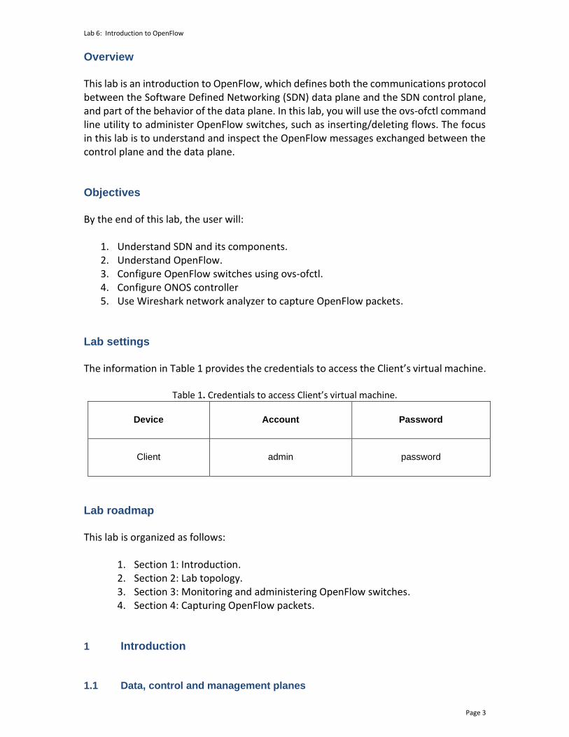
Figure 7. MiniEdit’s topology.
Step 3. Click on the Run button to start the emulation. The emulation will start and the buttons of the MiniEdit panel will gray out, indicating that they are currently disabled.
Figure 8. Starting the emulation.
3 Monitoring and administering OpenFlow switches
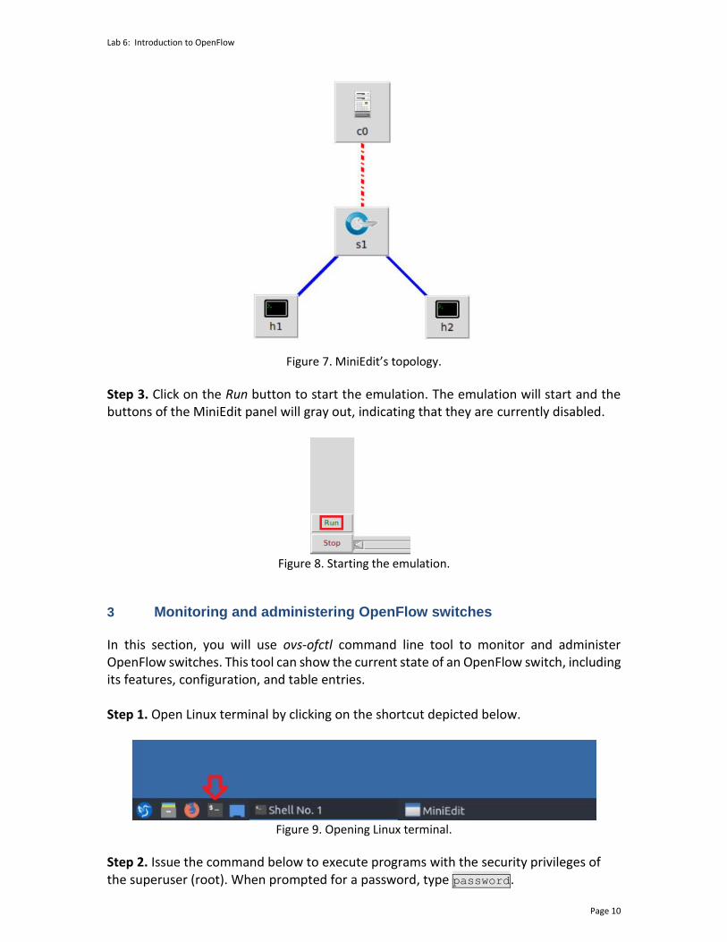
In this section, you will use ovs-ofctl command line tool to monitor and administer OpenFlow switches. This tool can show the current state of an OpenFlow switch, including its features, configuration, and table entries. Step 1. Open Linux terminal by clicking on the shortcut depicted below.
Figure 9. Opening Linux terminal.
Step 2. Issue the command below to execute programs with the security privileges of the superuser (root). When prompted for a password, type password.

Lab 6: Introduction to OpenFlow
Page 11
sudo su
Figure 10. Switching to root mode.
Step 3. Issue the command below to connect to switch s1 and show its information. ovs-ofctl show s1
Figure 11. Showing switch s1 information.
Consider Figure 11. Switch s1 has three interfaces. Each interface displays the Media Access Control (MAC) address (addr) along with other information, such as the current state of the switch.
Step 4. Issue the command below to print the flow entries of switch s1. ovs-ofctl dump-flows s1

Lab 6: Introduction to OpenFlow
Page 12
Figure 12. Showing the flow entries of switch s1.
Consider Figure 12. No output was shown in response to the above command. This is because initially the switch has no flow entries.
Step 5. Hold right-click on host h1 and select Terminal.
Figure 13. Opening host h1 terminal.
Step 6. Run a connectivity test by issuing the command shown below. The ping command is used to verify the connectivity between two ends. It must be followed by the IP address of the destination host, which is 10.0.0.2 (host h2) in this case. To stop the test, press Ctrl+c. ping 10.0.0.2
Figure 14. Pinging host h2 from host h1.
Consider Figure 14. The connectivity test is unsuccessful since switch s1 flow table is empty. Incoming traffic to the switch will not match any rule, and hence no action will be taken. Therefore, switch s1 doesn’t know what to do with incoming traffic, leading to ping failure.

Lab 6: Introduction to OpenFlow
Page 13
Step 7. Open Linux terminal.
Figure 15. Opening Linux terminal.
Step 8. Issue the below command to manually install a flow into switch s1. The inserted flow forwards incoming packets at port 1 (in_port=1) to port 2 (actions=output:2). ovs-ofctl add-flow s1 in_port=1,actions=output:2
Figure 16. Adding a flow entry to switch s1.
Step 9. Issue the below command to manually install a flow into switch s1. The inserted flow forwards incoming packets at port 2 (in_port=2) to port 1 (actions=output:1). ovs-ofctl add-flow s1 in_port=2,actions=output:1
Figure 17. Adding a flow entry to switch s1.
Step 10. Issue the command below to print the flow entries of switch s1.
Figure 18. Showing the flow entries of switch s1.
Step 11. In host h1, run a connectivity test with host h2 by issuing the following command. ping 10.0.0.2

Lab 6: Introduction to OpenFlow
Page 14
Figure 19. Pinging host h2 from host h1.
Step 12. In addition to adding flow entries to the switches using ovs-ofctl, you can also delete entries as well as deleting the whole flow table. Issue the following command on Linux terminal to delete the flow table of switch s1. ping 10.0.0.2
Figure 20. Deleting the flow table of switch s1.
4 Capturing OpenFlow packets In this section, you will start Wireshark, navigate through some of its features, and learn how to monitor network traffic. Additionally, you will enable ONOS controller and capture OpenFlow packets. 4.1 Starting Wireshark
In this section, you will use Wireshark, the defacto network protocol analyzer, to monitor the network and inspect OpenFlow packets that are being transmitted between the controller and the data plane (switch). Step 1. In Linux terminal, issue the following command to launch Wireshark. wireshark &
Lab 6: Introduction to OpenFlow
Page 15
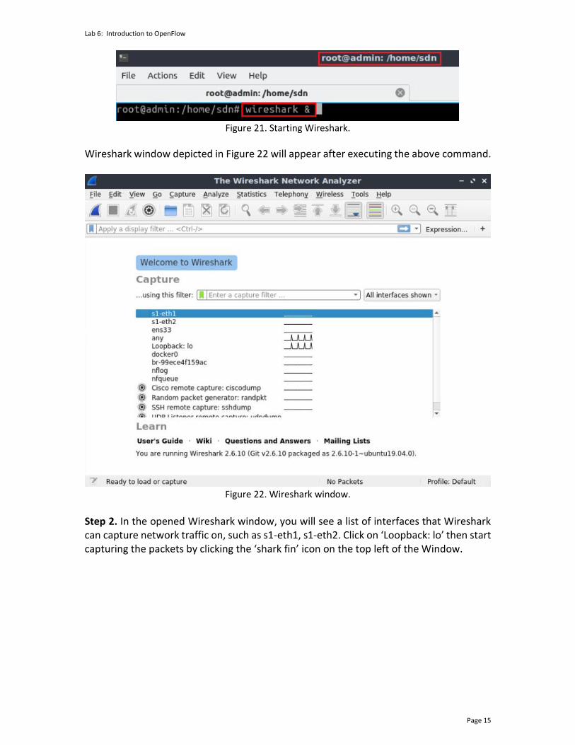
Figure 21. Starting Wireshark.
Wireshark window depicted in Figure 22 will appear after executing the above command.
Figure 22. Wireshark window.
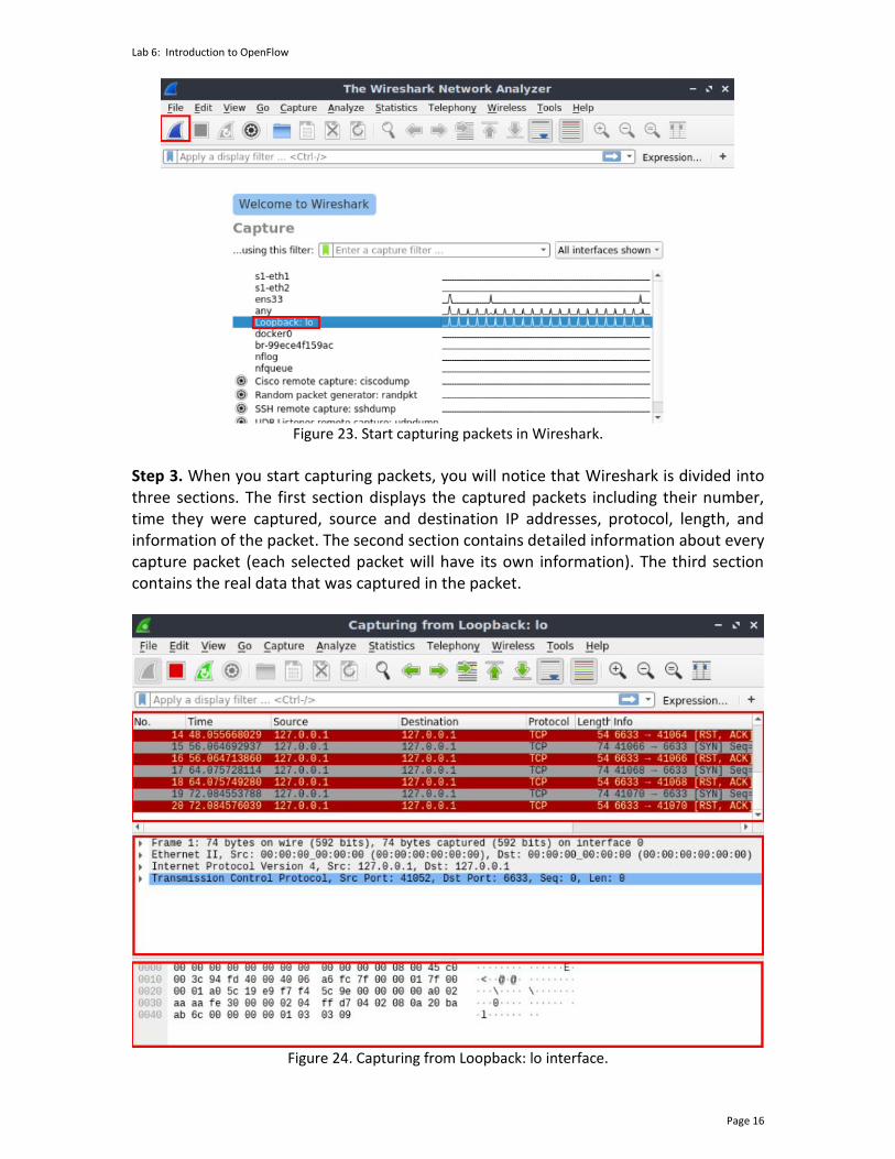
Step 2. In the opened Wireshark window, you will see a list of interfaces that Wireshark can capture network traffic on, such as s1-eth1, s1-eth2. Click on ‘Loopback: lo’ then start capturing the packets by clicking the ‘shark fin’ icon on the top left of the Window.
Lab 6: Introduction to OpenFlow
Page 16
Figure 23. Start capturing packets in Wireshark.
Step 3. When you start capturing packets, you will notice that Wireshark is divided into three sections. The first section displays the captured packets including their number, time they were captured, source and destination IP addresses, protocol, length, and information of the packet. The second section contains detailed information about every capture packet (each selected packet will have its own information). The third section contains the real data that was captured in the packet.
Figure 24. Capturing from Loopback: lo interface.

Lab 6: Introduction to OpenFlow
Page 17
Step 4. Wireshark supports filters, i.e., you can apply filters to display a specific set of capture packets. To show OpenFlow packets only (protocol: OpenFlow), write the following expression in Wireshark filter text box, then hit Enter. openflow_v1
Figure 25. Capturing only OpenFlow packets in Wireshark.
Consider Figure 25. The applied filter in Wireshark displays packets with protocol type OpenFlow only, specifically. No packets appear in the packet capturing section since we haven’t enabled the controller that exchanges OpenFlow packets with the data plane devices. 4.2 Starting ONOS controller
In this section, you will start ONOS controller and activate basic ONOS applications, such as OpenFlow application. The latter triggers the exchange of OpenFlow packets between the data plane (switch s1) and the control plane (c0). Thus, allowing the controller to discover the topology and insert flow entries into switch s1. Using Wireshark, you will capture the exchanged OpenFlow packets and understand their main types. Step 1. In Linux terminal, where Wireshark was launched, issue the following command to exit the superuser mode. exit
Figure 26. Exiting superuser mode.

Lab 6: Introduction to OpenFlow
Page 18
Step 2. Navigate into SDN_Labs/lab6 directory by issuing the following command. This folder contains the script responsible for starting ONOS. The cd command is short for change directory followed by an argument that specifies the destination directory. cd SDN_Labs/lab6
Figure 27. Entering the SDN_Labs/lab6 directory.
Step 3. A script was written to run ONOS and enter its Command Line Interface (CLI). In order to run the script, issue the following command. ./run_onos.sh
Figure 28. Starting ONOS.
Once the script finishes executing and ONOS is ready, you will be able to execute commands on ONOS CLI as shown in the figure below. Note that this script may take a couple of minutes.

Lab 6: Introduction to OpenFlow
Page 19
Figure 29. ONOS CLI.
Step 4. In ONOS terminal, issue the following command to activate the OpenFlow application. This application allows ONOS controller to discover the hosts, devices, and links in the current topology. app activate org.onosproject.openflow
Figure 30. Activating OpenFlow application.
Step 5. After activating the OpenFlow application, you should see a number of OpenFlow messages displayed in Wireshark as shown in the below figure.
Figure 31. Capturing OpenFlow packets using Wireshark.
Lab 6: Introduction to OpenFlow
Page 20
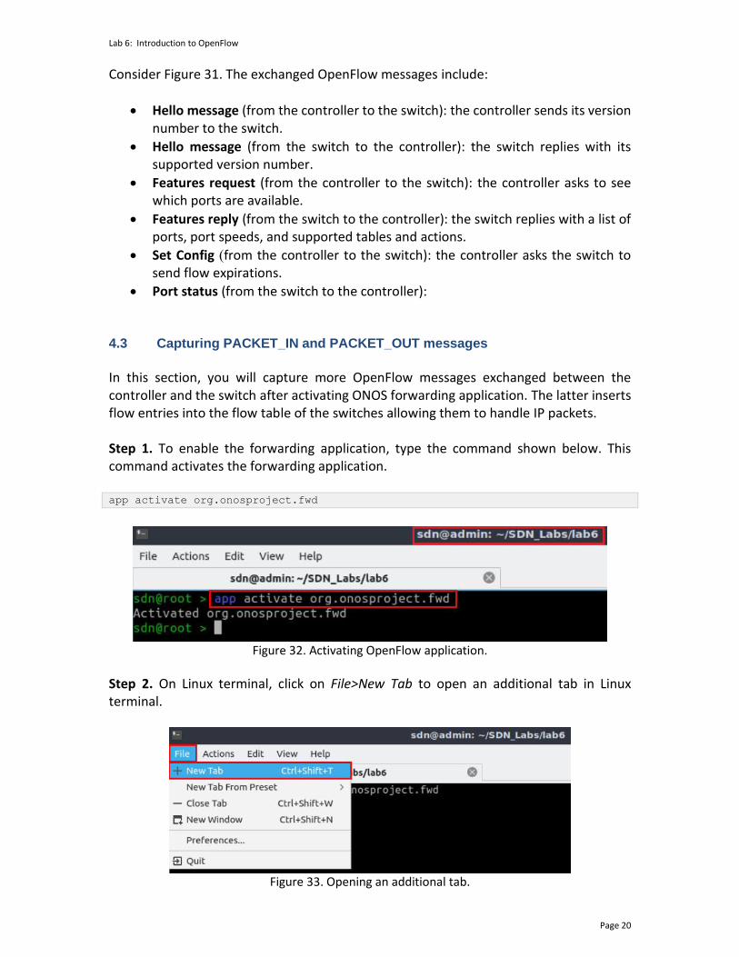
Consider Figure 31. The exchanged OpenFlow messages include:
• Hello message (from the controller to the switch): the controller sends its version number to the switch.
• Hello message (from the switch to the controller): the switch replies with its supported version number.
• Features request (from the controller to the switch): the controller asks to see which ports are available.
• Features reply (from the switch to the controller): the switch replies with a list of ports, port speeds, and supported tables and actions.
• Set Config )from the controller to the switch): the controller asks the switch to send flow expirations.
• Port status (from the switch to the controller): 4.3 Capturing PACKET_IN and PACKET_OUT messages
In this section, you will capture more OpenFlow messages exchanged between the controller and the switch after activating ONOS forwarding application. The latter inserts flow entries into the flow table of the switches allowing them to handle IP packets. Step 1. To enable the forwarding application, type the command shown below. This command activates the forwarding application. app activate org.onosproject.fwd
Figure 32. Activating OpenFlow application.
Step 2. On Linux terminal, click on File>New Tab to open an additional tab in Linux terminal.
Figure 33. Opening an additional tab.

Lab 6: Introduction to OpenFlow
Page 21
Step 3. Issue the command below to execute programs with the security privileges of the superuser (root). When prompted for a password, type password. sudo su
Figure 34. Switching to root mode.
Step 4. Issue the command below to print the flow entries of switch s1. ovs-ofctl dump-flows s1
Figure 35. Showing the flow entries of switch s1.
Consider Figure 35. Instead of manually adding entries in switch s1 flow table, ONOS controller inserted the above rules to discover the topology, as well as to manage incoming IP packets by forwarding them to the controller (ip actions=CONTROLLER:65535). Step 5. In host h1, ping host h2 and observe the captured packets in Wireshark. To do this, write the following command. ping 10.0.0.2
Figure 36. Pinging host h2 from host h1.

Lab 6: Introduction to OpenFlow
Page 22
Step 6. Go to Wireshark window and inspect the exchanged OpenFlow packets.
Figure 37. Capturing OpenFlow packets using Wireshark.
Consider Figure 37. During the pinging process from host h1 to host h2, you will notice a number of OpenFlow packets of the following types:
• PACKET_IN: the switch sends this message to the controller when a packet is received and didn’t match any entry in the switch’s flow table.
• PACKET_OUT: the controller sends a packet out one or more switch ports.
Other OpenFlow packet types include:
• OFPT_STATS_REQUEST: the controller sends this message type to query datapath's current state
• OFPT_STATS_REPLY: the switch responds to the request sent by the controller (OFPT_STATS_REQUEST)
Step 7. Stop capturing packets in Wireshark by clicking the red icon.
Figure 38. Stop Capturing Wireshark packets.
This concludes Lab 6. Stop the emulation and then exit out of MiniEdit and Linux terminal. References
1. Mininet walkthrough, [Online]. Available: http://mininet.org. 2. N. McKeown, T. Anderson, H. Balakrishnan, G. Parulkar, L. Peterson, J. Rexford, S.
Shenker, and J. Turner. "OpenFlow: enabling innovation in campus networks." ACM SIGCOMM Computer Communication Review 38, no. 2 (2008): 69-74.
3. P. Goransson, C. Black, T. Culver. “Software defined networks: a comprehensive approach”. Morgan Kaufmann, 2016.
4. P. Berde, M. Gerola, J. Hart, Y. Higuchi, M. Kobayashi, T. Koide, B. Lantz, "ONOS: towards an open, distributed SDN OS," In Proceedings of the third workshop on Hot topics in software defined networking, pp. 1-6, 2014.

![Introduction to SDN - start [APNIC TRAINING WIKI]€¦ · Introduction to SDN Agenda WSDN01_v1.0. Sessions ... Agenda • Day 1 – Introduction to SDN – Introduction to OpenFlow](https://img.pdfslide.net/doc/110x75/5f0f1e767e708231d442957f/introduction-to-sdn-start-apnic-training-wiki-introduction-to-sdn-agenda-wsdn01v10.jpg)


![OpenFlow Configuration Lab - start [APNIC TRAINING WIKI]](https://img.pdfslide.net/doc/110x75/61e686f20a811624b56dab03/openflow-configuration-lab-start-apnic-training-wiki.jpg)