Embed Size (px)
Citation preview

0
LAB MANNUAL
OF
FLUID MECHANICS (ME- 208E)
DEPTT. OF MECHANICAL ENGINEERING
OM INSTITUTE OF TECHNOLOGY & MANAGEMENT
12km Stone, NH-65, Chandigarh Road Juglan (Hisar) Web Site-www.oitmhisar.com, Email:- [email protected], Ph. No. 01662-264282, Fax-264281,
1
MECHANICAL ENGINEERING DEPARTMENT
LIST OF EXPERIMENTS OF FM
AS PER CURRICULUM
Sr.
No.
EXPERIMENT EXPERIMENT
NO.
PAGE
NO.
1 TO DETERMINE THE METACENTRIC HEIGHT
OF A GIVEN SHIP MODEL.
ME-FM-EX-01 1-3
2 TO STUDY THE MOMENTUM
CHARACTERISTICS OF A GIVEN JET.
ME-FM-EX-02 4-7
3 TO VERIFY THE BERNOULLI’S EQUATION ME-FM-EX-03 8-11
4 TO DETERMINE THE COEFFICIENT OF
DISCHARGE FOR AN ORFICEMETER
ME-FM-EX-04 12-14
5 TO DETERMINE THE COEFFICIENT OF
DISCHARGE FOR A VENTURIMETER
ME-FM-EX-05 15-17
6 TO DETERMINE THE COEFFICIENT OF
DISCHARGE FOR A GIVEN MOUTHPIECE
ME-FM-EX-06 18-20
7 TO DETERMINE THE COEFFICIENT OF
DISCHARGE FOR A GIVEN ORFICE PLATE.
ME-FM-EX-07 21-23
8 TO VERIFY COEFFICIENT OF HEADLOSS IN
SUDDEN CONTRACTION
ME-FM-EX-08 24-26
9 TO CALIBARATE A SHARP-CRESTED
RECTANGULAR WEIR.
ME-FM-EX-09 27-28
10 TO CALIBERATE A V-NOTCH. ME-FM-EX-10 29-31
LIST OF EXPERIMENTS BEYONG CURRICULUM:
11 TO CALIBRATE A TRAPEZOIDAL -NOTCH. ME-FM-EX-11 32-34
12 TO DETERMINE THE COEFFICIENT OF DISCHARGE
FOR DIVERGENT MOUTHPIECE.
ME-FM-EX-12 35-37
2
Experiment No 1:
Objective : To determine the metacentric height of a given ship model.
Equipment Used : A pantoon floating in a tank. Removable strips, graduated arc
with pointer, movable, hangers, set of weight.
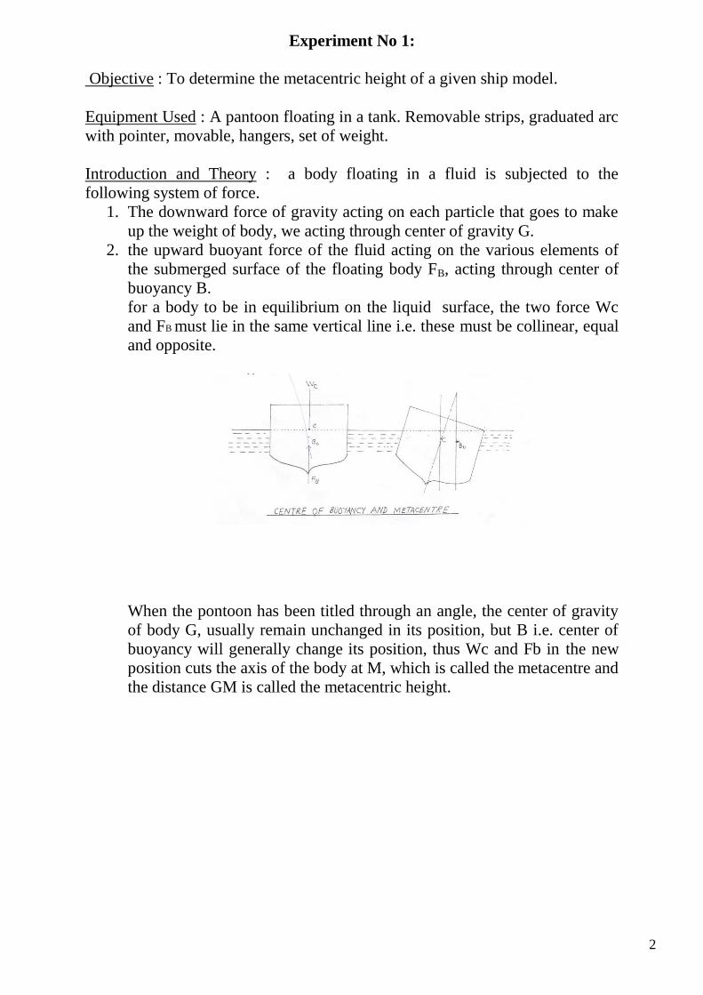
Introduction and Theory : a body floating in a fluid is subjected to the
following system of force.
1. The downward force of gravity acting on each particle that goes to make
up the weight of body, we acting through center of gravity G.
2. the upward buoyant force of the fluid acting on the various elements of
the submerged surface of the floating body FB, acting through center of
buoyancy B.
for a body to be in equilibrium on the liquid surface, the two force Wc
and FB must lie in the same vertical line i.e. these must be collinear, equal
and opposite.
When the pontoon has been titled through an angle, the center of gravity
of body G, usually remain unchanged in its position, but B i.e. center of
buoyancy will generally change its position, thus Wc and Fb in the new
position cuts the axis of the body at M, which is called the metacentre and
the distance GM is called the metacentric height.
3
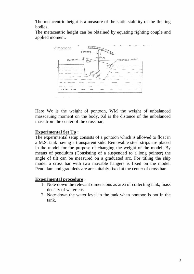
The metacentric height is a measure of the static stability of the floating
bodies.
The metacentric height can be obtained by equating righting couple and
applied moment.
Here Wc is the weight of pontoon, WM the weight of unbalanced
masscauing moment on the body, Xd is the distance of the unbalanced
mass from the center of the cross bar,
Experimental Set Up :
The experimental setup consists of a pontoon which is allowed to float in
a M.S. tank having a transparent side. Removable steel strips are placed
in the model for the purpose of changing the weight of the model. By
means of pendulum (Consisting of a suspended to a long pointer) the
angle of tilt can be measured on a graduated arc. For titling the ship
model a cross bar with two movable hangers is fixed on the model.
Pendulam and graduleds are arc suitably fixed at the center of cross bar.
Experimental procedure :
1. Note down the relevant dimensions as area of collecting tank, mass
density of water etc.
2. Note down the water level in the tank when pontoon is not in the
tank.
4
3. pontoon is allowed to float in the tank. Note down the reading of
water in the tank. Mass of pontoon can be obtained by the help of
Archmidie’s principle.
4. Position of unbalanced mass, weight of unbalanced mass, and the
angle of heel can be noted down. Calculate the Metacentric height
of the pontoon.
5. The procedure is repeated for other position and value of
unbalanced mass. Also the procedure is repeated while changing
the number of strips in the pontoon.
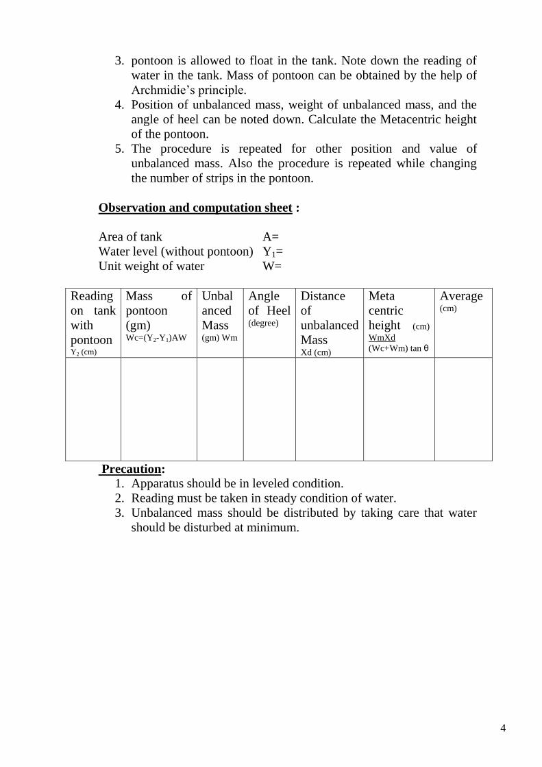
Observation and computation sheet :
Area of tank A=
Water level (without pontoon) Y1=
Unit weight of water W=
Reading
on tank
with
pontoon Y2 (cm)
Mass of
pontoon
(gm) Wc=(Y2-Y1)AW
Unbal
anced
Mass (gm) Wm
Angle
of Heel (degree)
Distance
of
unbalanced
Mass Xd (cm)
Meta
centric
height (cm)
WmXd
(Wc+Wm) tan θ
Average (cm)
Precaution:
1. Apparatus should be in leveled condition.
2. Reading must be taken in steady condition of water.
3. Unbalanced mass should be distributed by taking care that water
should be disturbed at minimum.
5
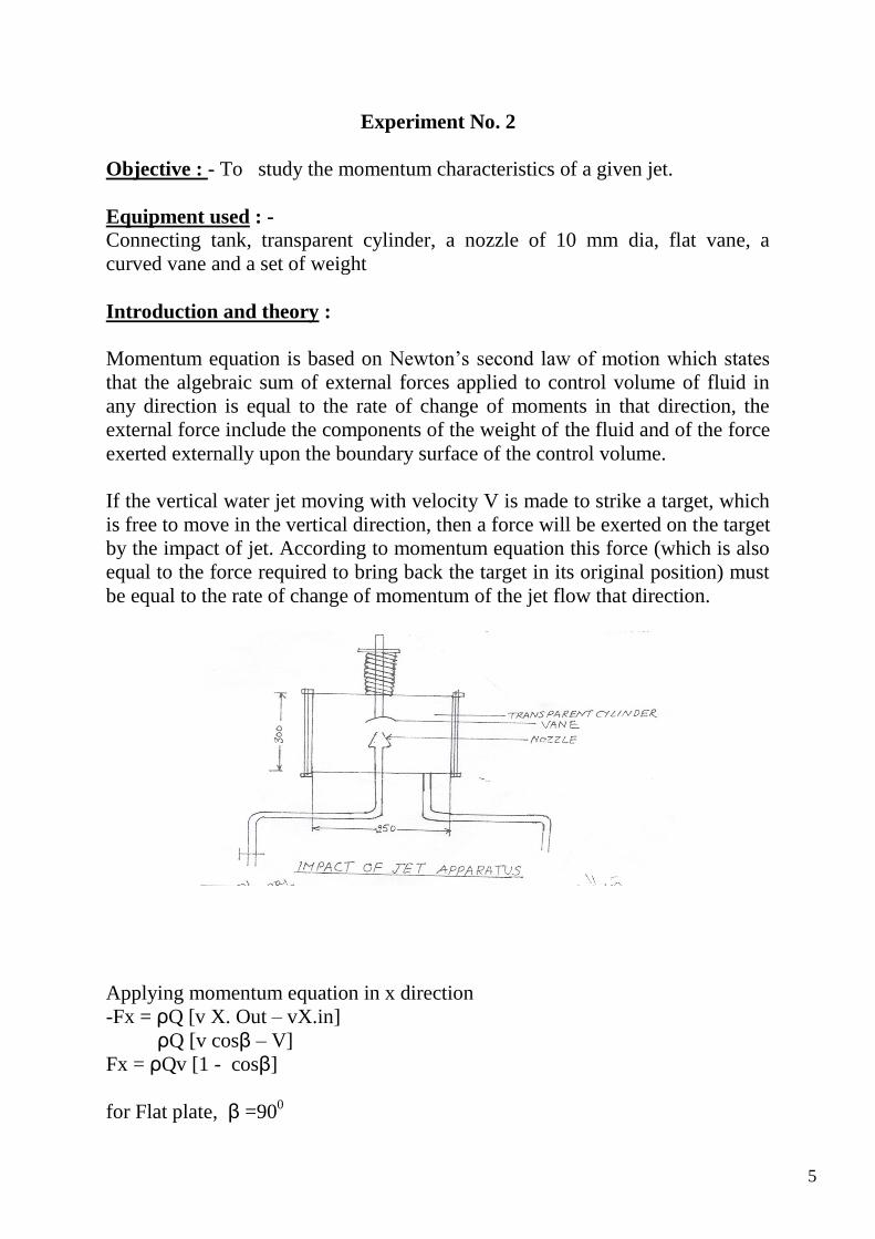
Experiment No. 2
Objective : - To study the momentum characteristics of a given jet.
Equipment used : - Connecting tank, transparent cylinder, a nozzle of 10 mm dia, flat vane, a
curved vane and a set of weight
Introduction and theory :
Momentum equation is based on Newton’s second law of motion which states
that the algebraic sum of external forces applied to control volume of fluid in
any direction is equal to the rate of change of moments in that direction, the
external force include the components of the weight of the fluid and of the force
exerted externally upon the boundary surface of the control volume.
If the vertical water jet moving with velocity V is made to strike a target, which
is free to move in the vertical direction, then a force will be exerted on the target
by the impact of jet. According to momentum equation this force (which is also
equal to the force required to bring back the target in its original position) must
be equal to the rate of change of momentum of the jet flow that direction.
Applying momentum equation in x direction
-Fx = ρQ [v X. Out – vX.in]
ρQ [v cosβ – V]
Fx = ρQv [1 - cosβ]
for Flat plate, β =900
6
Fx= ρQv
For Hemispherical Cup, β =1800
Fx= 2ρ Qv
Here, ρ is the Mass Density, Q The Discharge Through The Nozzle, V the
Velocity at the exit of nozzle (i.e.q/a) and a is the area of cross section of
nozzle.
Fx= ………….
While for curved hemispherical vane the force is
Fx= -------------------
Experimental set up : The experimental set up primarily consist of nozzle through which a water jet
images vertically in such a way it may be conveniently observed through the
transparent cyclinder, it strikes the target vane positioned above it. The force
applied on the vane by jet can be measured by applying weight to counteract the
reaction of the jet. Vanes are interchangeable i.e. Flat or curved vane.
7
Arrangement is made for the movement of the plate under the action of the jet
and also because of the weight placed on the loading pan. A scale for the jet
strikes the vane. A collecting tank is used to find the actual discharge and
velocity through the nozzle.
Experiment procedure : Note down the relevant dimension as area of collection tank, mass density of
water and dia of nozzle.
The flat plate is intalled.
When the jet is not running, not down the position of upper disc.
The water supply is admitted to the nozzle and the flow rate is adjusted to its
maximum value.
As the jet strikes the vane, position of the upper disc is changed. Now place the
weight to bring back the upper disc to original position.
At this position find out the discharge as well as note down weights places on
the upper disc.
The procedure is repeated for each value of flow rate by reducing the water
supply in steps.
The procedure is repeated with the installation if curved vane in the apparatus.
Observation and computation sheet : i. Dia of nozzle (mm) =
Mass density of water p =
Area of collecting tank =
Area of nozzle, a =
8
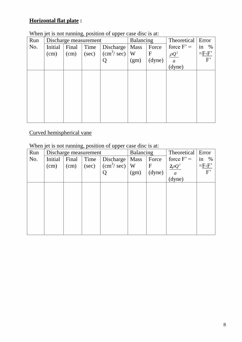
Horizontal flat plate :
When jet is not running, position of upper case disc is at:
Run
No.
Discharge measurement Balancing Theoretical
force F’ =
a
Q 2
(dyne)
Error
in %
=F-F’
F’
Initial
(cm)
Final
(cm)
Time
(sec)
Discharge
(cm3/ sec)
Q
Mass
W
(gm)
Force
F
(dyne)
Curved hemispherical vane
When jet is not running, position of upper case disc is at:
Run
No.
Discharge measurement Balancing Theoretical
force F’ =
a
Q22
(dyne)
Error
in %
=F-F’
F’
Initial
(cm)
Final
(cm)
Time
(sec)
Discharge
(cm3/ sec)
Q
Mass
W
(gm)
Force
F
(dyne)
9
EXPERIMENT NO. 3
Objective: To verify the Bernoulli’s equation.
Equipment used :
Inlet supply tank with overflow arrangement, outlet supply tank with
means of Varyingflow rate, Perspex duct of varying cross-section and a
series of piezometric tubes installed along its length.
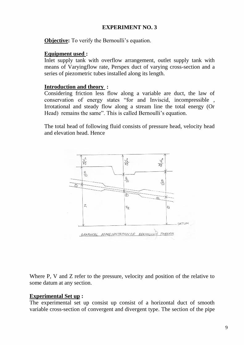
Introduction and theory :
Considering friction less flow along a variable are duct, the law of
conservation of energy states “for and Inviscid, incompressible ,
Irrotational and steady flow along a stream line the total energy (Or
Head) remains the same”. This is called Bernoulli’s equation.
The total head of following fluid consists of pressure head, velocity head
and elevation head. Hence
Where P, V and Z refer to the pressure, velocity and position of the relative to
some datum at any section.
Experimental Set up :
The experimental set up consist up consist of a horizontal duct of smooth
variable cross-section of convergent and divergent type. The section of the pipe
10
is 40 mm at the entrance and the exit and 20 mm at middle. The total length of
duct is 90 cm. The piezometric pressure P at the location of pressure tapings is
measured by means if 11 piezometer tubes installed at an equal distance of 7.5
cm along the length of conduit, the duct is connected with supply tanks at its
entrance and exit end with flow rate. A collection tank is used to find the actual
discharge.
Experimental procedure : 1. Note down the piezometer distance from intel section of the Perspex duct.
2. Note down the cross section area of perspex duct at each of the
piezometer tapping points.
3. The datum head is treated as constant through out the duct.
4. By maintaining suitable amount of steady head or nearby steady head
condition in the supply tanks, three establishes a steady no unifirm flow
in the conduit.
5. The discharge flowing in the conduit is recorded together with the water
levels in each piezometer tubes.
6. This procedure is repeated for other value of discharge.
Observation :
If V is the velocity of flow at a particular section of the duct and Q is the
discharge, then by continuity equation
V= Q
Area of section
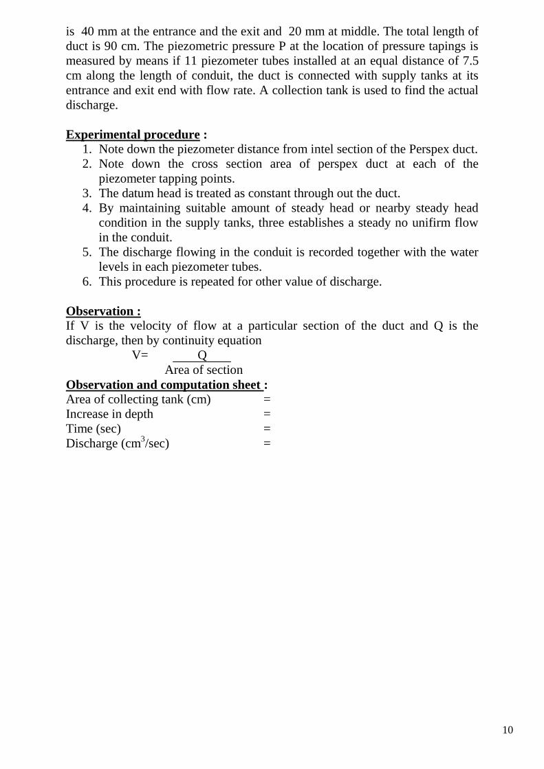
Observation and computation sheet :
Area of collecting tank (cm) =
Increase in depth =
Time (sec) =
Discharge (cm3/sec) =
11
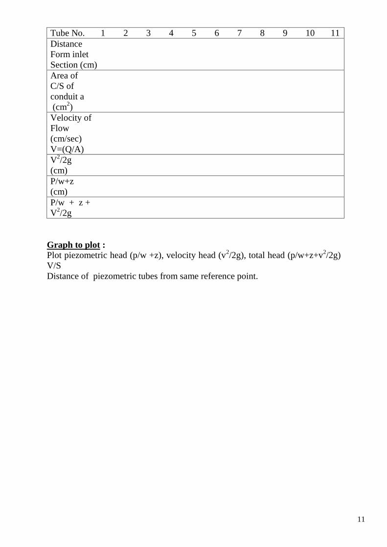
Tube No. 1 2 3 4 5 6 7 8 9 10 11
Distance
Form inlet
Section (cm)
Area of
C/S of
conduit a
(cm2)
Velocity of
Flow
(cm/sec)
V=(Q/A)
V2/2g
(cm)
P/w+z
(cm)
P/w + z +
V2/2g
Graph to plot :
Plot piezometric head (p/w +z), velocity head (v2/2g), total head (p/w+z+v
2/2g)
V/S
Distance of piezometric tubes from same reference point.
12
Comment :
Since the conduit is horizontal, the total energy at any section with reference to
the datum line of the conduit is the sum of p/w and v2/2g (here w is the weight
density of the fluid and g is acceleration due to gravity). One can compare the
value of the total energy at different sections and comment about the constancy
of energy in converging and diverging conduit.
Precautions :
1. Apparatus should be in leveled condition.
2. Reading must be taken in steady or near by steady conditions. And it
should be noted that water level in the inlet supply tank should reach the
overflow condition.
3. There should not be any air bubble in the piezometer and in the perspex
duct.
4. By closing the regulating value, open the control value slightly such that
the water level in the inlet supply tank reaches the overflow conditions.
At this stage check that pressure head in each piezometer tube is equal. If
not adjust the piezometers to bring it equal.
13
Experiment No 4
Objective: To determine the coefficient of discharge for a given orifice meter.
Equipment used :
Orificemeter fitted in a horizontal pipeline with means of varying flow rate, U
tube differential manometer.
Introduction and theory : The Orificemeter are devices used for measurement of rate of flow of fluid
through a pipe. The basis principle, on which Orificemeter work is that by
reducing the cross sectional area of passage, a pressure difference is created and
the measurement of the pressure difference enables the determination of the
discharge through the pipe.
An Orificemeter is a cheaper arrangement for measurement of discharge
through pipes and its installation requires a smaller length as compared with
venturi meter.
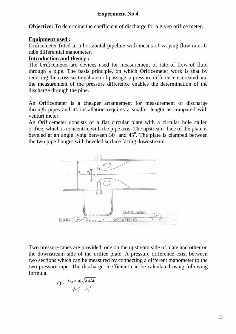
An Orificemeter consists of a flat circular plate with a circular hole called
orifice, which is concentric with the pipe axis. The upstream face of the plate is
beveled at an angle lying between 300 and 45
0. The plate is clamped between
the two pipe flanges with beveled surface facing downstream.
Two pressure tapes are provided, one on the upstream side of plate and other on
the downstream side of the orifice plate. A pressure difference exist between
two sections which can be measured by connecting a different manometer to the
two pressure tape. The discharge coefficient can be calculated using following
formula.
Q = 2
0
2
1
1 2
aa
hgaaC od
14
Where Cd is coefficient of orifice, a0 is cross-sectional area of orifice, a1 is cross
sectional area of pipe, g is the acceleration due to gravity and ∆h is the
difference of head in terms of water.
Experimental setup :
The experimental setup consists of a circuit through which the fluid is circulated
continuously having a Orifice meter of 25 mm dia and having a
d/D=0.6. The Orificemeter has two pressure tapings at upstream and
downstream. A U tube mercury manometer with common manifold is pressure
the pressure difference between two sections. A collecting tank is provided to
find the actual discharge through the circuit.
Experimental procedure: 1. Note down the relevant dimensions as diameter of pipeline, dia of orifice,
area of collecting tank, room temperature etc.
2. Pressure taping of Orificemeter are kept open.
3. The flow rate is adjusted to its maximum value.
4. By maintain suitable amount of steady flow in the pipe circuit, there
establishes a steady no uniform flow in the conduit. Time is allowed to
stabilize the levels in the manometer tube.
5. The discharge flowing in the circuit is recorded together with the water
levels in left and right limbs of manometer tube.
6. The flow rate is reduces in steady by means of flow control value and the
discharge & reading of manometer are recorded.
7. This procedure is repeated by closing the pressure taping of Orificemeter.
Observation and computation sheet:
ORIFIC METER:
Diameter of main pipe line, D =
The ratio d/D = 0.6
Area of cross section of orifice a0 =
Area of cross section of inlet section a1 =
Area of collecting tank
15
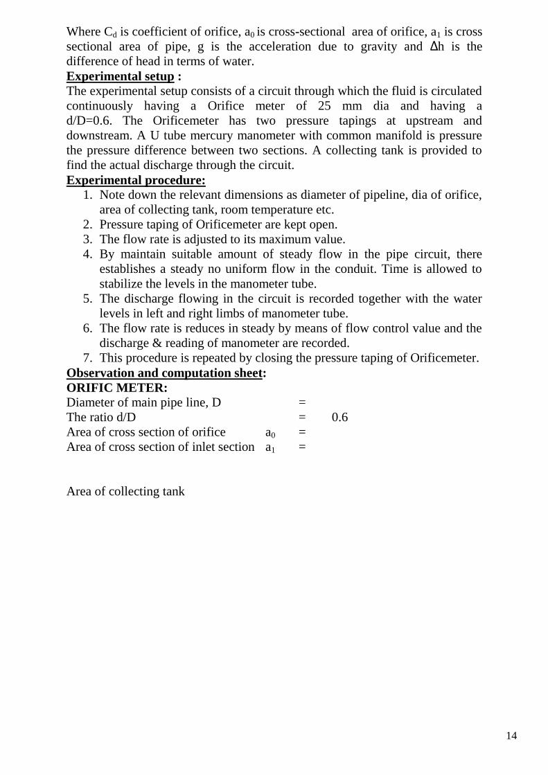
Sr
No.
Discharge Measurement Manometer Reading
Cd=
hgaa
aaQ
210
2
0
2
1
Initial
(cm)
Final
(cm)
Time
(sec)
Discharge
(cm3/ sec)
Q
Rise
in left
h1(cm)
Rise in
right
limb
h2(cm)
∆h in terms
of water
head=12.6x(
h1-h2)
Average Cd =
Graph to plot: plot a graph between Q vs ∆ h.
16
Experiment No 5
Objective : To determine coefficient of discharge for a given venture meter.
Equipment used :
Venturimeter fitted in a horizontal pipe line with means of varying flow rate, U
tube different manometer.
Introduction and theory:
The Venturimeter are devices used for measurement of rate of flow of fluid
through a pipe. The basis principle on which a Venturimeter work is that by
reducing the cross sectional area of flow passage, a pressure difference is
created and the measurement of the pressure difference enables the
determination of the discharge through the pipe.
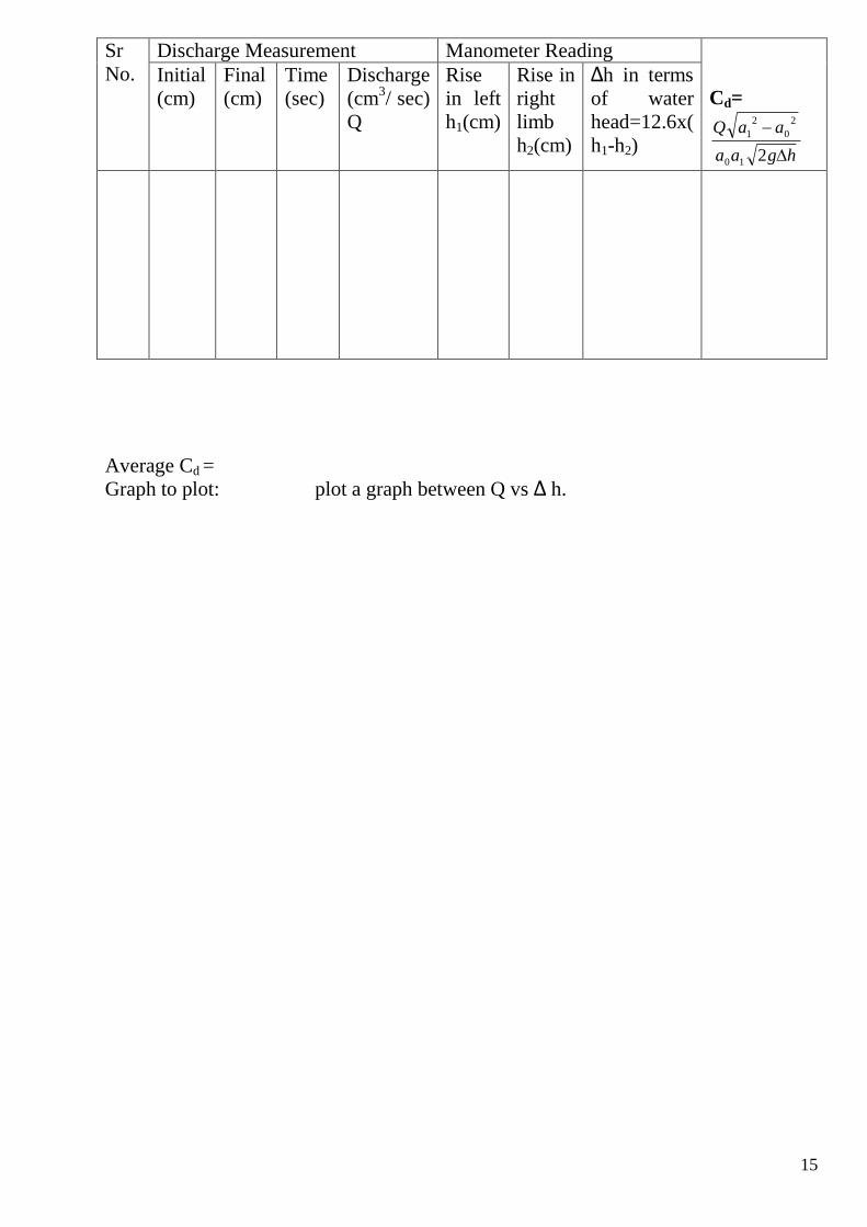
A Venturimeter consists of (1) an inlet section followed by a convergent cone,
(2) a cyclindrical throat and (3) a gradually divergent cone. Since the cross-
sectional area of the inlet section, the velocity of flow at the throat will become
greater than that at th einlet section, according to continuity equation. The
increase in the velocity of flow at the throat result in the decrease in the pressure
at this section. A pressure difference is created between the inlet section and
throat section which can be determined by connecting a different U-tube
manometer between the pressure tape provided at these sections. The
17
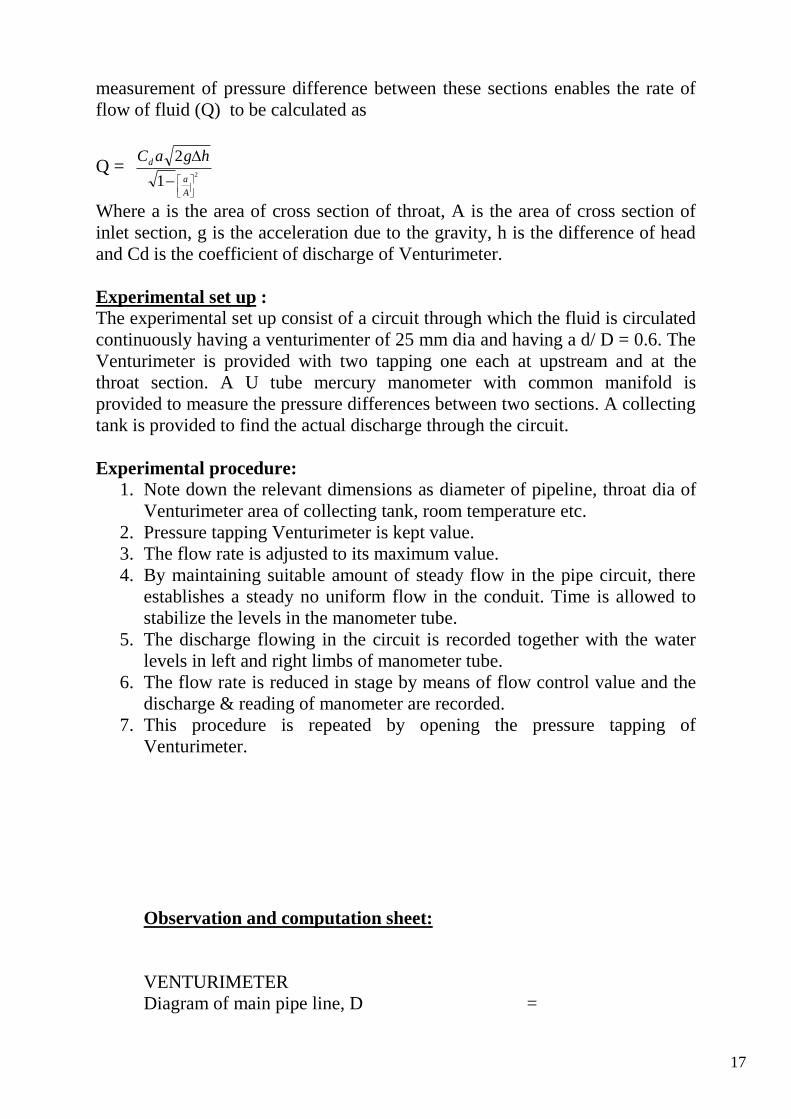
measurement of pressure difference between these sections enables the rate of
flow of fluid (Q) to be calculated as
Q = 2
1
2
A
a
d hgaC
Where a is the area of cross section of throat, A is the area of cross section of
inlet section, g is the acceleration due to the gravity, h is the difference of head
and Cd is the coefficient of discharge of Venturimeter.
Experimental set up :
The experimental set up consist of a circuit through which the fluid is circulated
continuously having a venturimenter of 25 mm dia and having a d/ D = 0.6. The
Venturimeter is provided with two tapping one each at upstream and at the
throat section. A U tube mercury manometer with common manifold is
provided to measure the pressure differences between two sections. A collecting
tank is provided to find the actual discharge through the circuit.
Experimental procedure:
1. Note down the relevant dimensions as diameter of pipeline, throat dia of
Venturimeter area of collecting tank, room temperature etc.
2. Pressure tapping Venturimeter is kept value.
3. The flow rate is adjusted to its maximum value.
4. By maintaining suitable amount of steady flow in the pipe circuit, there
establishes a steady no uniform flow in the conduit. Time is allowed to
stabilize the levels in the manometer tube.
5. The discharge flowing in the circuit is recorded together with the water
levels in left and right limbs of manometer tube.
6. The flow rate is reduced in stage by means of flow control value and the
discharge & reading of manometer are recorded.
7. This procedure is repeated by opening the pressure tapping of
Venturimeter.
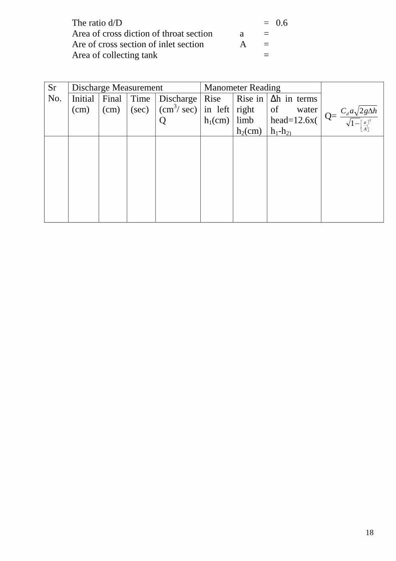
Observation and computation sheet:
VENTURIMETER
Diagram of main pipe line, D =
18
The ratio d/D = 0.6
Area of cross diction of throat section a =
Are of cross section of inlet section A =
Area of collecting tank =
Sr
No.
Discharge Measurement Manometer Reading
Q= 2
1
2
A
a
d hgaC
Initial
(cm)
Final
(cm)
Time
(sec)
Discharge
(cm3/ sec)
Q
Rise
in left
h1(cm)
Rise in
right
limb
h2(cm)
∆h in terms
of water
head=12.6x(
h1-h2)
19
EXPERIMENT NO 6
Objective : To determine the coefficient of discharge for a given mouthpiece.
Equipment Used :-
Supply tank with overflow arrangement and provision of fitting of orifice or
mouth piece installed in the vertical plane of the tank side, scale and sliding
apparatus with hook gauge, a set of mouthpiece.
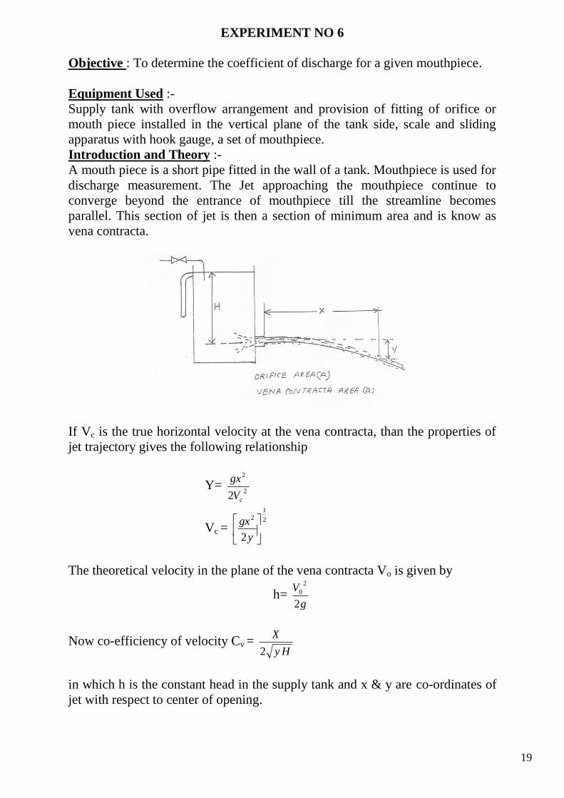
Introduction and Theory :-
A mouth piece is a short pipe fitted in the wall of a tank. Mouthpiece is used for
discharge measurement. The Jet approaching the mouthpiece continue to
converge beyond the entrance of mouthpiece till the streamline becomes
parallel. This section of jet is then a section of minimum area and is know as
vena contracta.
If Vc is the true horizontal velocity at the vena contracta, than the properties of
jet trajectory gives the following relationship
Y= 2
2
2 cV
gx
Vc = 2
12
2
y
gx
The theoretical velocity in the plane of the vena contracta Vo is given by
h= g
V
2
2
0
Now co-efficiency of velocity Cv = Hy
X
2
in which h is the constant head in the supply tank and x & y are co-ordinates of
jet with respect to center of opening.
20
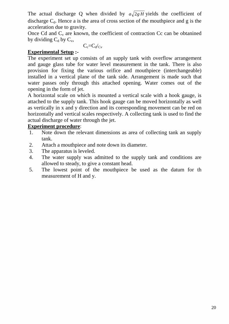
The actual discharge Q when divided by Hga 2 yields the coefficient of
discharge Cd. Hence a is the area of cross section of the mouthpiece and g is the
acceleration due to gravity.
Once Cd and Cv are known, the coefficient of contraction Cc can be obtanined
by dividing Cd by Cv,
Cc=Cd/Cv
Experimental Setup :-
The experiment set up consists of an supply tank with overflow arrangement
and gauge glass tube for water level measurement in the tank. There is also
provision for fixing the various orifice and mouthpiece (interchangeable)
installed in a vertical plane of the tank side. Arrangement is made such that
water passes only through this attached opening. Water comes out of the
opening in the form of jet.
A horizontal scale on which is mounted a vertical scale with a hook gauge, is
attached to the supply tank. This hook gauge can be moved horizontally as well
as vertically in x and y direction and its corresponding movement can be red on
horizontally and vertical scales respectively. A collecting tank is used to find the
actual discharge of water through the jet.
Experiment procedure:
1. Note down the relevant dimensions as area of collecting tank an supply
tank.
2. Attach a mouthpiece and note down its diameter.
3. The apparatus is leveled.
4. The water supply was admitted to the supply tank and conditions are
allowed to steady, to give a constant head.
5. The lowest point of the mouthpiece be used as the datum for th
measurement of H and y.
21
6. The discharge flowing through the jet was recorded together with the
water level in the supply tank.
7. A series of reading of dimensions x an y was taken a long the trajectory
of the jet.
8. The procedure is repeated by means of slow control value.
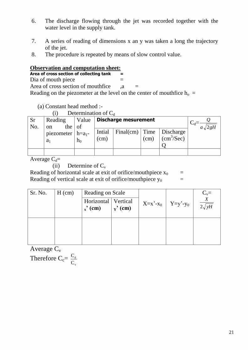
Observation and computation sheet: Area of cross section of collecting tank =
Dia of mouth piece =
Area of cross section of mouthfice ,a =
Reading on the piezometer at the level on the center of mouthfice ho =
(a) Constant head method :-
(i) Determination of Cd
Sr
No.
Reading
on the
piezometer
a1
Value
of
h=a1-
h0
Discharge mesurement Cd=
gHa
Q
2
Intial
(cm)
Final(cm) Time
(cm)
Discharge
(cm3/Sec)
Q
Average Cd=
(ii) Determine of Cv
Reading of horizontal scale at exit of orifice/mouthpiece x0 =
Reading of vertical scale at exit of orifice/mouthpiece y0 =
Sr. No. H (cm) Reading on Scale
X=x’-x0 Y=y’-y0
Cv=
yH
X
2
Horizontal
x’ (cm)
Vertical
Y’ (cm)
Average Cv
Therefore Cc= v
d
C
C
22
EXPERIMENT NO.7
Objective: To determine the coefficients of discharge for a given orifice plate.
Equipment used:
Supply tank with overflow arrangement and provision of fitting of orifice or
mouth piece installed in the vertical plane of the tank side, scale and sliding
apparatus with hook gauge, a set of orifice 15 mm dia.
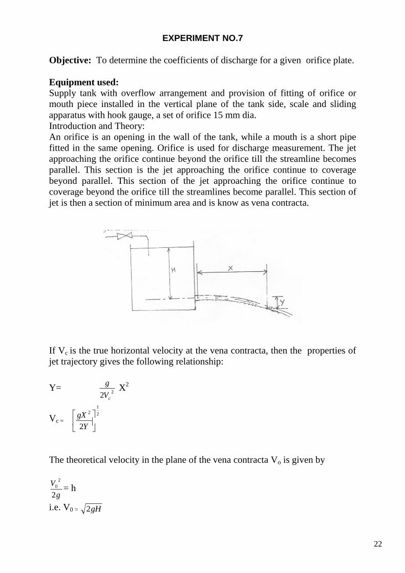
Introduction and Theory:
An orifice is an opening in the wall of the tank, while a mouth is a short pipe
fitted in the same opening. Orifice is used for discharge measurement. The jet
approaching the orifice continue beyond the orifice till the streamline becomes
parallel. This section is the jet approaching the orifice continue to coverage
beyond parallel. This section of the jet approaching the orifice continue to
coverage beyond the orifice till the streamlines become parallel. This section of
jet is then a section of minimum area and is know as vena contracta.
If Vc is the true horizontal velocity at the vena contracta, then the properties of
jet trajectory gives the following relationship:
Y= 2
2 cV
g X
2
Vc =
2
12
2
Y
gX
The theoretical velocity in the plane of the vena contracta Vo is given by
g
V
2
2
0 = h
i.e. V0 = gH2
23
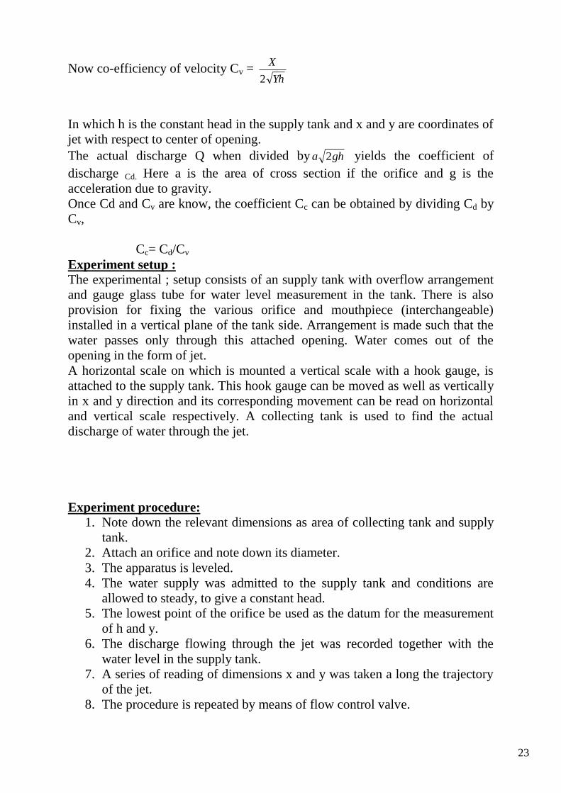
Now co-efficiency of velocity Cv = Yh
X
2
In which h is the constant head in the supply tank and x and y are coordinates of
jet with respect to center of opening.
The actual discharge Q when divided by gha 2 yields the coefficient of
discharge Cd. Here a is the area of cross section if the orifice and g is the
acceleration due to gravity.
Once Cd and Cv are know, the coefficient Cc can be obtained by dividing Cd by
Cv,
Cc= Cd/Cv
Experiment setup :
The experimental ; setup consists of an supply tank with overflow arrangement
and gauge glass tube for water level measurement in the tank. There is also
provision for fixing the various orifice and mouthpiece (interchangeable)
installed in a vertical plane of the tank side. Arrangement is made such that the
water passes only through this attached opening. Water comes out of the
opening in the form of jet.
A horizontal scale on which is mounted a vertical scale with a hook gauge, is
attached to the supply tank. This hook gauge can be moved as well as vertically
in x and y direction and its corresponding movement can be read on horizontal
and vertical scale respectively. A collecting tank is used to find the actual
discharge of water through the jet.
Experiment procedure:
1. Note down the relevant dimensions as area of collecting tank and supply
tank.
2. Attach an orifice and note down its diameter.
3. The apparatus is leveled.
4. The water supply was admitted to the supply tank and conditions are
allowed to steady, to give a constant head.
5. The lowest point of the orifice be used as the datum for the measurement
of h and y.
6. The discharge flowing through the jet was recorded together with the
water level in the supply tank.
7. A series of reading of dimensions x and y was taken a long the trajectory
of the jet.
8. The procedure is repeated by means of flow control valve.
24
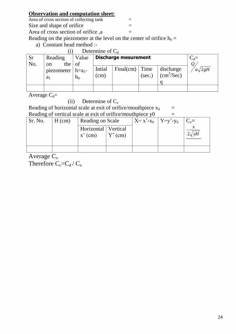
Observation and computation sheet: Area of cross section of collecting tank =
Size and shape of orifice =
Area of cross section of orifice ,a =
Reading on the piezometer at the level on the center of orifice h0 =
a) Constant head method :-
(i) Determine of Cd
Sr
No.
Reading
on the
piezometer
a1
Value
of
h=a1-
h0
Discharge mesurement Cd=
gHa
Q
2
Intial
(cm)
Final(cm) Time
(sec.)
discharge
(cm3/Sec)
q
Average Cd=
(ii) Determine of Cv
Reading of horizontal scale at exit of orifice/mouthpiece x0 =
Reading of vertical scale at exit of orifice/mouthpiece y0 =
Sr. No. H (cm) Reading on Scale X= x’-x0 Y=y’-y0 Cv=
yH
x
2
Horizontal
x’ (cm)
Vertical
Y’ (cm)
Average Cv
Therefore Cc=Cd / Cv
25
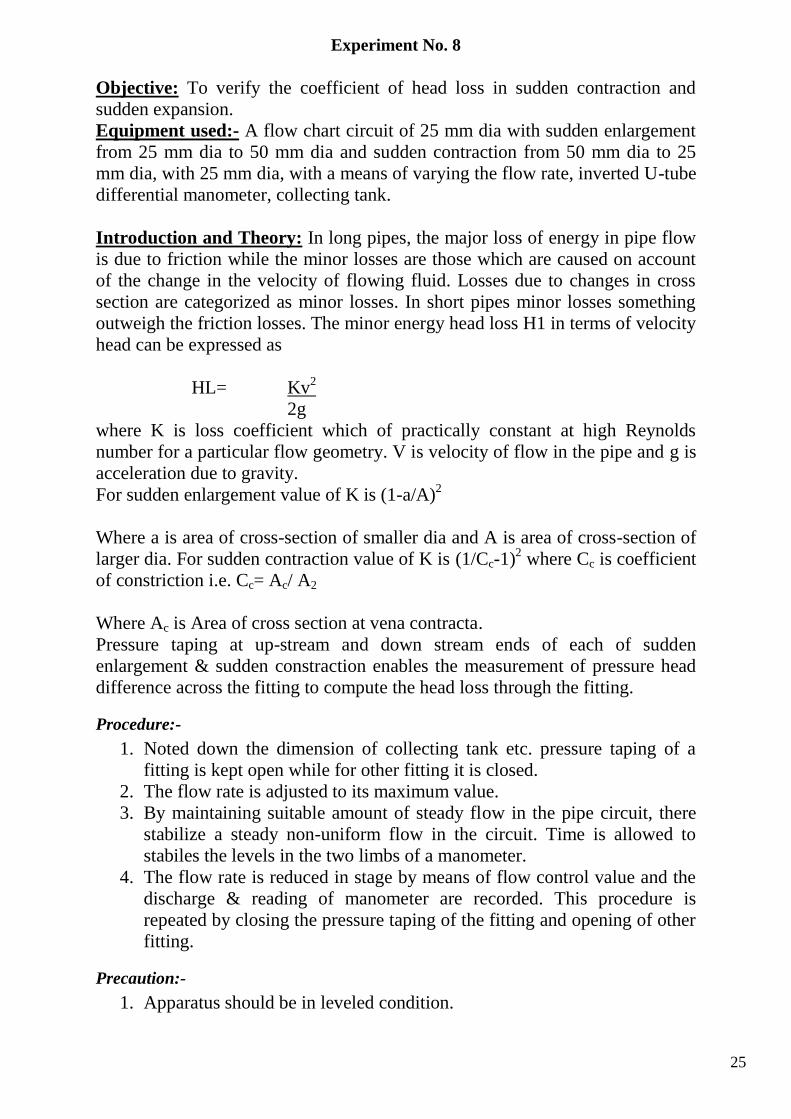
Experiment No. 8
Objective: To verify the coefficient of head loss in sudden contraction and
sudden expansion.
Equipment used:- A flow chart circuit of 25 mm dia with sudden enlargement
from 25 mm dia to 50 mm dia and sudden contraction from 50 mm dia to 25
mm dia, with 25 mm dia, with a means of varying the flow rate, inverted U-tube
differential manometer, collecting tank.
Introduction and Theory: In long pipes, the major loss of energy in pipe flow
is due to friction while the minor losses are those which are caused on account
of the change in the velocity of flowing fluid. Losses due to changes in cross
section are categorized as minor losses. In short pipes minor losses something
outweigh the friction losses. The minor energy head loss H1 in terms of velocity
head can be expressed as
HL= Kv2
2g
where K is loss coefficient which of practically constant at high Reynolds
number for a particular flow geometry. V is velocity of flow in the pipe and g is
acceleration due to gravity.
For sudden enlargement value of K is (1-a/A)2
Where a is area of cross-section of smaller dia and A is area of cross-section of
larger dia. For sudden contraction value of K is (1/Cc-1)2 where Cc is coefficient
of constriction i.e. Cc= Ac/ A2
Where Ac is Area of cross section at vena contracta.
Pressure taping at up-stream and down stream ends of each of sudden
enlargement & sudden constraction enables the measurement of pressure head
difference across the fitting to compute the head loss through the fitting.
Procedure:-
1. Noted down the dimension of collecting tank etc. pressure taping of a
fitting is kept open while for other fitting it is closed.
2. The flow rate is adjusted to its maximum value.
3. By maintaining suitable amount of steady flow in the pipe circuit, there
stabilize a steady non-uniform flow in the circuit. Time is allowed to
stabiles the levels in the two limbs of a manometer.
4. The flow rate is reduced in stage by means of flow control value and the
discharge & reading of manometer are recorded. This procedure is
repeated by closing the pressure taping of the fitting and opening of other
fitting.
Precaution:-
1. Apparatus should be in leveled condition.
26
2. Reading must be taken in steady or near by steady conditions.
3. There should be no initial difference of the water levels in the manometer
limbs was observed to be zero.
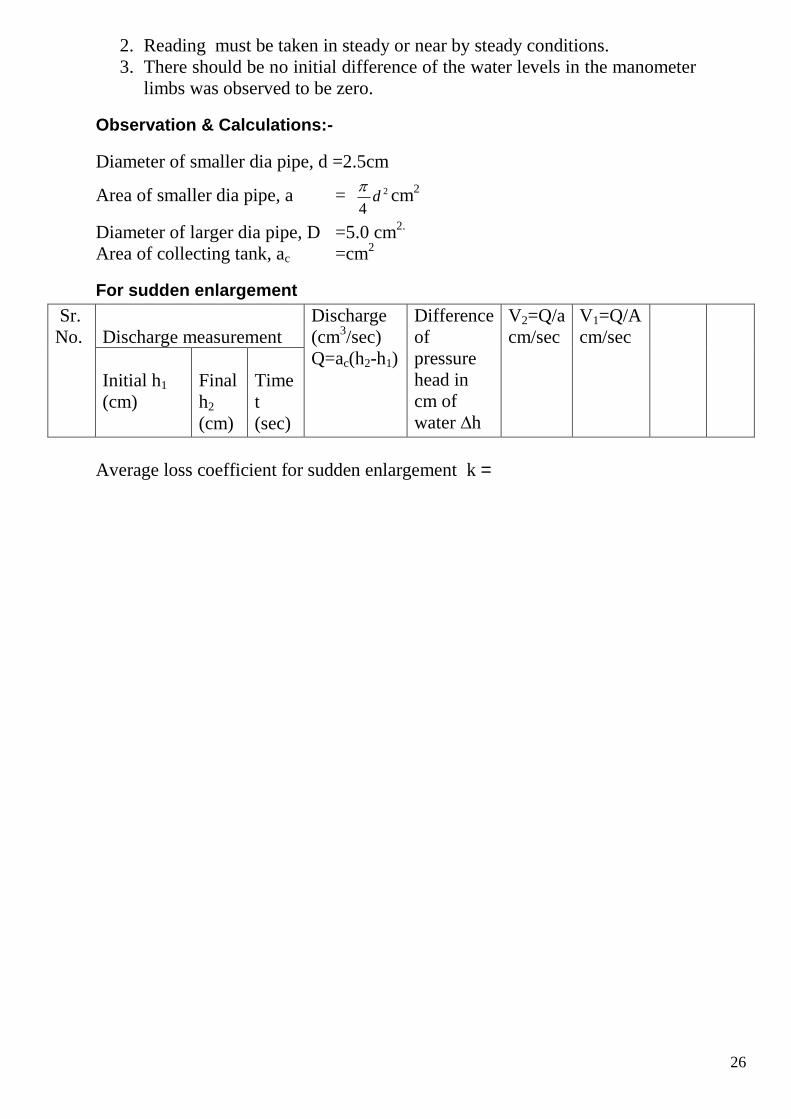
Observation & Calculations:-
Diameter of smaller dia pipe, d =2.5cm
Area of smaller dia pipe, a = 2
4d
cm
2
Diameter of larger dia pipe, D =5.0 cm2.
Area of collecting tank, ac =cm2
For sudden enlargement
Sr.
No.
Discharge measurement
Discharge
(cm3/sec)
Q=ac(h2-h1)
Difference
of
pressure
head in
cm of
water ∆h
V2=Q/a
cm/sec
V1=Q/A
cm/sec
Initial h1
(cm)
Final
h2
(cm)
Time
t
(sec)
Average loss coefficient for sudden enlargement k =
27
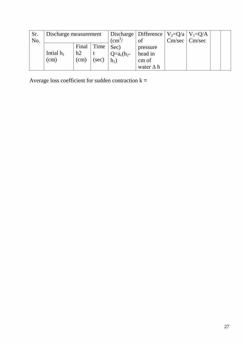
Sr.
No.
Discharge measurement Discharge
(cm3/
Sec)
Q=ac(h2-
h1)
Difference
of
pressure
head in
cm of
water ∆ h
V2=Q/a
Cm/sec
V1=Q/A
Cm/sec
Intial h1
(cm)
Final
h2
(cm)
Time
t
(sec)
Average loss coefficient for sudden contraction k =
28
Experiment No. 9
Objective: To calibrate a sharp created rectangular weir.
Equipment used: A constant steady water supply tank (Notch tank) with baffles wall, pointer
gauge, collecting tank, and models.
Introduction and Theory: Different type of models are available to find discharge in an open channel as
notch, venturimeter weir etc. for calibration of either rectangular notch,
trapezoidal notch some flow is allowed in the flume. Once the flow becomes
steady and uniform discharge coefficients can be for any model.
In general, sharp crested notches are preferred where highly accurate discharge
measurement is required, for example in hydraulic laboratories, industries and
irrigation pilot schemes, which do not carry debris and sediments.
Notches are those overflow structure whose length of crest in the direction of
flow is accurately shaped. There may be rectangular, trapezoidal, V notch etc.
the relationship between discharge and head over the weir can be developed by
making the following assumptions as to the flow behavior.
a. Upstream of the weir, the flow is uniform and the pressure varies with
depth according to the hydrostatic equation P= gh.
b. The free surface remains horizontal as far as the plane of the weir , and all
particles passing over the weir move horizontally.
c. The pressure through out the sheet of liquid which passes over the crest
of the weir, is atmospheric.
d. The effect of viscosity and surface tension are negligible.
e. The velocity in the approach channel is negligible.
A rectangular notch, symmetrically located in a vertical thin plate, which is
placed perpendicular to the side and bottom of a straight channel, is defined as a
rectangular sharp-crested weirs. The discharge coefficient Cd of a rectangular
notch my be determined by applying formula
Q= gCd 23
2BH 2
3
Where Q is the discharge over a rectangular notch, B is the width of notch , H is
the head over the crest of the notch and g is acceleration due to gravity.
Experiment setup:
The experiment setup consist of a tank whose inlet section is provided with –2
nos. of baffles for stream line flow. While at the downstream portion of the
tank one can fix a notch of either rectangular notch, trapezoidal notch or V-
notch. A hook gauge is used to measure the head of water over the model. A
collecting tank is used to find the actual discharge through the notch
29
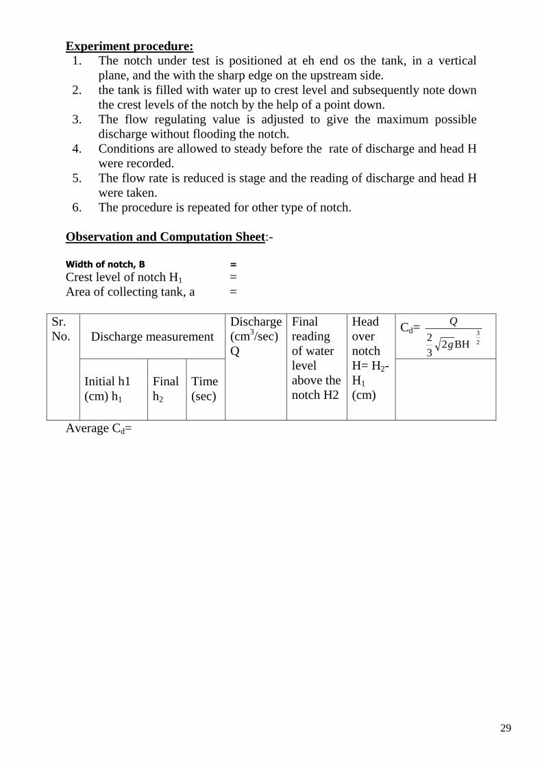
Experiment procedure: 1. The notch under test is positioned at eh end os the tank, in a vertical
plane, and the with the sharp edge on the upstream side.
2. the tank is filled with water up to crest level and subsequently note down
the crest levels of the notch by the help of a point down.
3. The flow regulating value is adjusted to give the maximum possible
discharge without flooding the notch.
4. Conditions are allowed to steady before the rate of discharge and head H
were recorded.
5. The flow rate is reduced is stage and the reading of discharge and head H
were taken.
6. The procedure is repeated for other type of notch.
Observation and Computation Sheet:-
Width of notch, B =
Crest level of notch H1 =
Area of collecting tank, a =
Sr.
No. Discharge measurement
Discharge
(cm3/sec)
Q
Final
reading
of water
level
above the
notch H2
Head
over
notch
H= H2-
H1
(cm)
Cd= 2
3
BH23
2g
Q
Initial h1
(cm) h1
Final
h2
Time
(sec)
Average Cd=
30
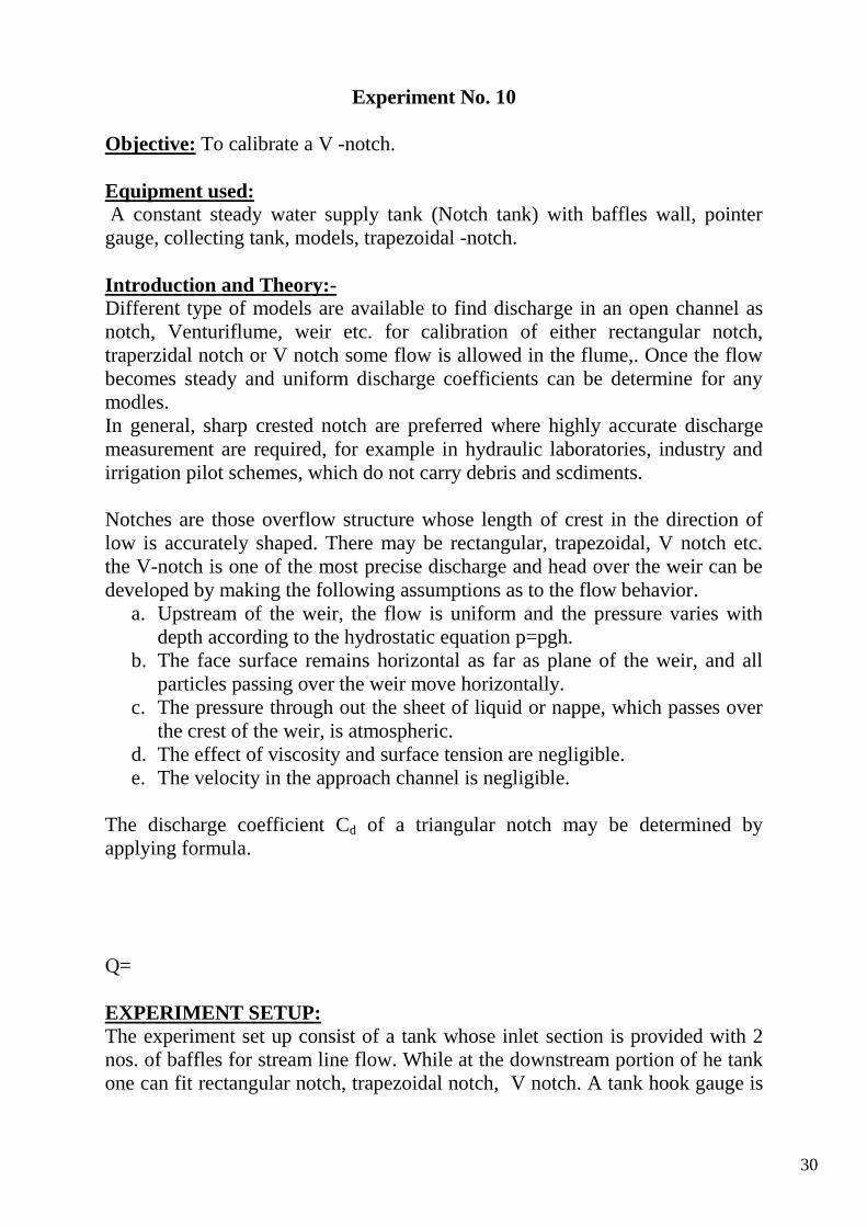
Experiment No. 10
Objective: To calibrate a V -notch.
Equipment used:
A constant steady water supply tank (Notch tank) with baffles wall, pointer
gauge, collecting tank, models, trapezoidal -notch.
Introduction and Theory:- Different type of models are available to find discharge in an open channel as
notch, Venturiflume, weir etc. for calibration of either rectangular notch,
traperzidal notch or V notch some flow is allowed in the flume,. Once the flow
becomes steady and uniform discharge coefficients can be determine for any
modles.
In general, sharp crested notch are preferred where highly accurate discharge
measurement are required, for example in hydraulic laboratories, industry and
irrigation pilot schemes, which do not carry debris and scdiments.
Notches are those overflow structure whose length of crest in the direction of
low is accurately shaped. There may be rectangular, trapezoidal, V notch etc.
the V-notch is one of the most precise discharge and head over the weir can be
developed by making the following assumptions as to the flow behavior.
a. Upstream of the weir, the flow is uniform and the pressure varies with
depth according to the hydrostatic equation p=pgh.
b. The face surface remains horizontal as far as plane of the weir, and all
particles passing over the weir move horizontally.
c. The pressure through out the sheet of liquid or nappe, which passes over
the crest of the weir, is atmospheric.
d. The effect of viscosity and surface tension are negligible.
e. The velocity in the approach channel is negligible.
The discharge coefficient Cd of a triangular notch may be determined by
applying formula.
Q=
EXPERIMENT SETUP:
The experiment set up consist of a tank whose inlet section is provided with 2
nos. of baffles for stream line flow. While at the downstream portion of he tank
one can fit rectangular notch, trapezoidal notch, V notch. A tank hook gauge is
31
used to measure the head of water over the model. A collecting is used to find
the actual discharge through the notch.
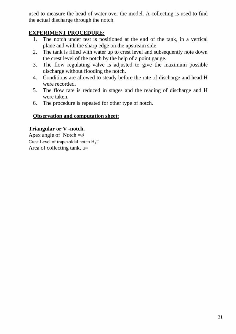
EXPERIMENT PROCEDURE:
1. The notch under test is positioned at the end of the tank, in a vertical
plane and with the sharp edge on the upstream side.
2. The tank is filled with water up to crest level and subsequently note down
the crest level of the notch by the help of a point gauge.
3. The flow regulating valve is adjusted to give the maximum possible
discharge without flooding the notch.
4. Conditions are allowed to steady before the rate of discharge and head H
were recorded.
5. The flow rate is reduced in stages and the reading of discharge and H
were taken.
6. The procedure is repeated for other type of notch.
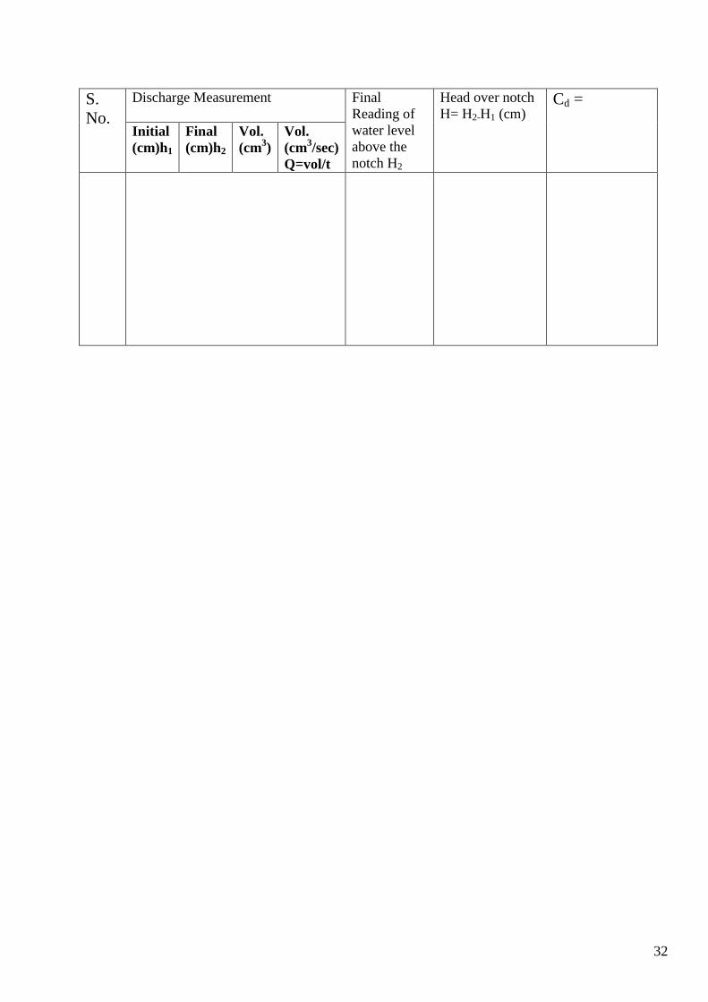
Observation and computation sheet:
Triangular or V -notch.
Apex angle of Notch =
Crest Level of trapezoidal notch H1=
Area of collecting tank, a=
32
S.
No.
Discharge Measurement Final
Reading of
water level
above the
notch H2
Head over notch
H= H2-H1 (cm) Cd =
Initial
(cm)h1
Final
(cm)h2
Vol.
(cm3)
Vol.
(cm3/sec)
Q=vol/t
33
Experiment No. 11
Objective: To calibrate a trapezoidal -notch
Equipment used:
A constant steady water supply tank (Notch tank) with baffles wall, pointer
gauge, collecting tank, models, trapezoidal -notch.
Introduction and Theory:- Different type of models are available to find discharge in an open channel as
notch, Venturiflume, weir etc. for calibration of either rectangular notch,
trapezoidal notch or V notch some flow is allowed in the flume,. Once the flow
becomes steady and uniform discharge coefficients can be determine for any
models.
In general, sharp crested notch are preferred where highly accurate discharge
measurement are required, for example in hydraulic laboratories, industry and
irrigation pilot schemes, which do not carry debris and sediments.
Notches are those overflow structure whose length of crest in the direction of
low is accurately shaped. There may be rectangular, trapezoidal, V notch etc.
the V-notch is one of the most precise discharge and head over the weir can be
developed by making the following assumptions as to the flow behavior.
a. Upstream of the weir, the flow is uniform and the pressure varies with
depth according to the hydrostatic equation p= gh
b. The face surface remains horizontal as far as plane of the weir, and all
particles passing over the weir move horizontally.
c. The pressure through out the sheet of liquid which passes over the crest
of the weir is atmospheric.
d. The effect of viscosity and surface tension are negligible.
e. The velocity in the approach channel is negligible.
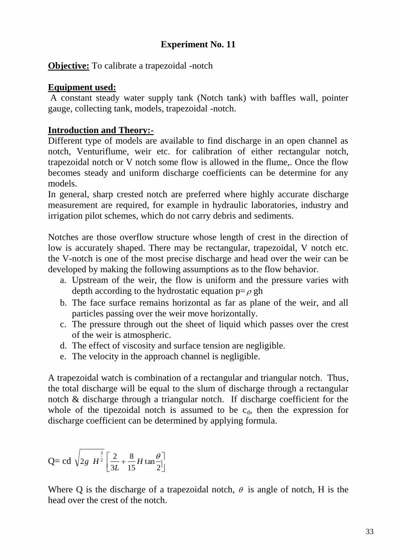
A trapezoidal watch is combination of a rectangular and triangular notch. Thus,
the total discharge will be equal to the slum of discharge through a rectangular
notch & discharge through a triangular notch. If discharge coefficient for the
whole of the tipezoidal notch is assumed to be cd, then the expression for
discharge coefficient can be determined by applying formula.
Q= cd
2tan
15
8
3
22 2
3
HL
Hg
Where Q is the discharge of a trapezoidal notch, is angle of notch, H is the
head over the crest of the notch.
34
EXPERIMENT SETUP:
The experiment set up consist of a tank whose inlet section is provided with 2
nos. of baffles for stream line flow. While at the downstream portion of the tank
one can fit rectangular notch, trapezoidal notch, V notch. A tank hook gauge is
used to measure the head of water over the model. A collecting is used to find
the actual discharge through the notch.
EXPERIMENT PROCEDURE: 1. The notch under test is positioned at the end of the tank, in a vertical
plane and with the sharp edge on the upstream side.
2. The tank is filled with water up to crest level and subsequently note down
the crest level of the notch by the help of a point gauge.
3. The flow regulating valve is adjusted to give the maximum possible
discharge without flooding the notch.
4. Conditions are allowed to steady before the rate of discharge and head H
were recorded.
5. The flow rate is reduced in stages and the reading of discharge and H
were taken.
6. The procedure is repeated for other type of notch.
Observation and computation sheet:
Trapezoidal -notch.
Apex angle of Notch 2
=12.4
Crest Level of trapezoidal notch H1=
Area of collecting tank, a=
L= length of the crest of the notch =10.5
35
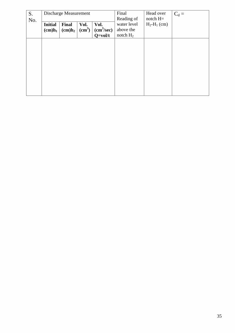
S.
No.
Discharge Measurement Final
Reading of
water level
above the
notch H2
Head over
notch H=
H2-H1 (cm)
Cd =
Initial
(cm)h1
Final
(cm)h2
Vol.
(cm3)
Vol.
(cm3/sec)
Q=vol/t
36
EXPERIMENT NO. 12
Objective: To determine the coefficient of discharge for divergent
mouthpiece.
Equipment Used: Supply tank with overflow arrangement and provision
of fitting of orifice or mouth piece installed in the vertical plane of the
tank., slide, scale and sliding apparatus with hook gauge, a set of
mouthpiece.
INTRODUCTION AND THEORY
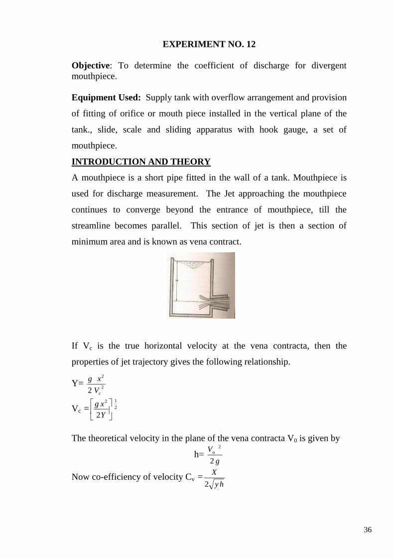
A mouthpiece is a short pipe fitted in the wall of a tank. Mouthpiece is
used for discharge measurement. The Jet approaching the mouthpiece
continues to converge beyond the entrance of mouthpiece, till the
streamline becomes parallel. This section of jet is then a section of
minimum area and is known as vena contract.
If Vc is the true horizontal velocity at the vena contracta, then the
properties of jet trajectory gives the following relationship.
Y= 2
2
2 cV
xg
Vc = 2
12
2
Y
xg
The theoretical velocity in the plane of the vena contracta V0 is given by
h= g
Vo
2
2
Now co-efficiency of velocity Cv =hy
X
2
37
In which h is the constant head in the supply tank and x and y are coordinates of
jet with respect to center of opening.
The actual discharge Q when divided by a gh2 yields the coefficient of
discharge Cd. Here a is the area of cross section if the orifice and g is the
acceleration due to gravity.
Once Cd and Cv are know, the coefficient Cc can be obtained by dividing Cd by
Cv,
Cc=Cd/Cv
Experiment setup :
The experimental setup consists of an supply tank with overflow arrangement
and gauge glass tube for water level measurement in the tank. There is also
provision for fixing the various orifices and mouthpiece (interchangeable)
installed in a vertical plane of the tank side. Arrangement is made such that the
water passes only through this attached opening. Water comes out of the
opening in the form of jet.
A horizontal scale on which is mounted a vertical scale with a hook gauge, is
attached to the supply tank. This hook gauge can be moved as well as vertically
in x and y direction and its corresponding movement can be read on horizontal
and vertical scale respectively. A collecting tank is used to find the actual
discharge of water through the jet.
Experiment procedure: .
1. Note down the relevant dimensions as area of collecting tank an supply
tank.
2. Attach a mouthpiece and note down its diameter.
3. The apparatus is leveled.
4. The water supply was admitted to the supply tank and conditions are
allowed to steady, to give a constant head.
5. The lowest point of the mouthpiece be used as the datum for th
measurement of H and y.
6. The discharge flowing through the jet was recorded together with the
water level in the supply tank.
7. A series of reading of dimensions x and y was taken a long the trajectory
of the jet.
8. The procedure is repeated by means of slow control value.
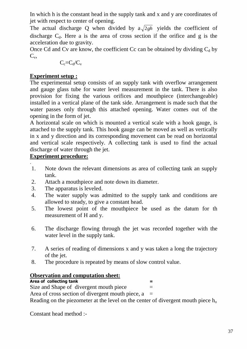
Observation and computation sheet: Area of collecting tank =
Size and Shape of divergent mouth piece =
Area of cross section of divergent mouth piece, a =
Reading on the piezometer at the level on the center of divergent mouth piece ho
Constant head method :-
38
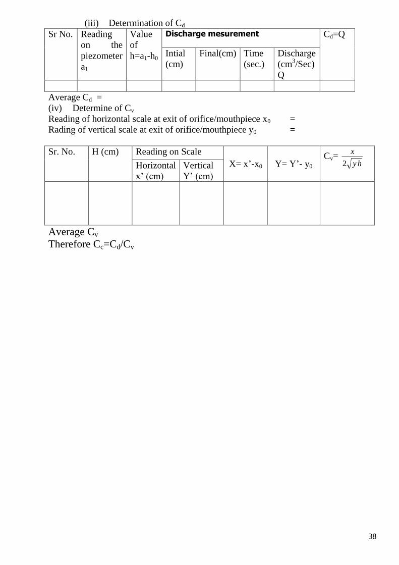
(iii) Determination of Cd
Sr No. Reading
on the
piezometer
a1
Value
of
h=a1-h0
Discharge mesurement Cd=Q
Intial
(cm)
Final(cm) Time
(sec.)
Discharge
(cm3/Sec)
Q
Average Cd =
(iv) Determine of Cv
Reading of horizontal scale at exit of orifice/mouthpiece x0 =
Rading of vertical scale at exit of orifice/mouthpiece y0 =
Sr. No. H (cm) Reading on Scale
X= x’-x0 Y= Y’- y0 Cv=
hy
x
2
Horizontal
x’ (cm)
Vertical
Y’ (cm)
Average Cv
Therefore Cc=Cd/Cv