Embed Size (px)
DESCRIPTION
lab work
Citation preview
Lab Session#5
ExpErimEnt#5 Verification of KVL loop equation
Discussion: Kirchhoff’s Voltage Law states that the total voltage supplied by the voltage source is equal to the sum of all voltage drops across each resistor. Which means that the sum of all voltage drops around a closed loop is equal to zero.
Circuit Diagram for verifying KVL
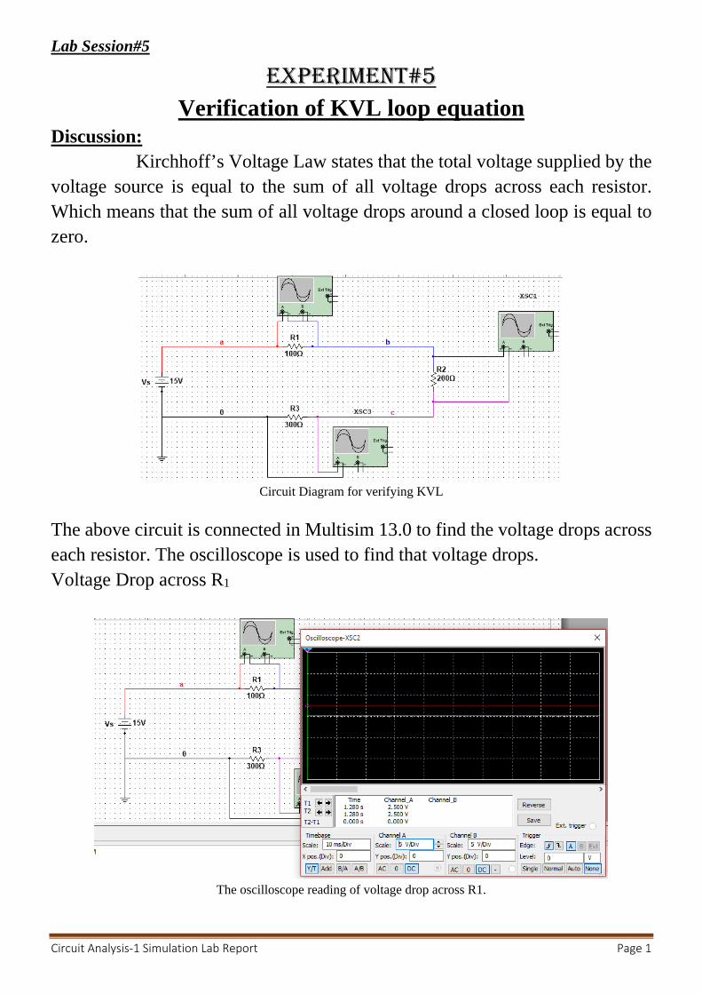
The above circuit is connected in Multisim 13.0 to find the voltage drops across each resistor. The oscilloscope is used to find that voltage drops. Voltage Drop across R1
The oscilloscope reading of voltage drop across R1.
Circuit Analysis-1 Simulation Lab Report Page 1
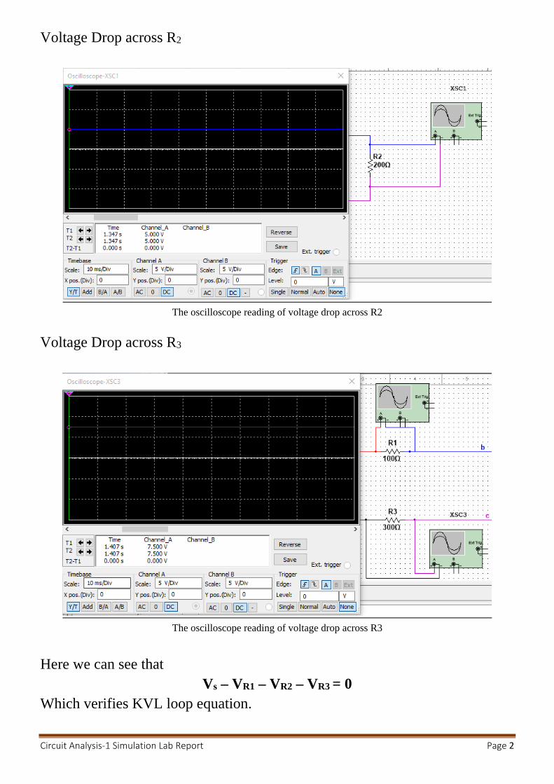
Voltage Drop across R2
The oscilloscope reading of voltage drop across R2
Voltage Drop across R3
The oscilloscope reading of voltage drop across R3
Here we can see that
Vs – VR1 – VR2 – VR3 = 0 Which verifies KVL loop equation. Circuit Analysis-1 Simulation Lab Report Page 2
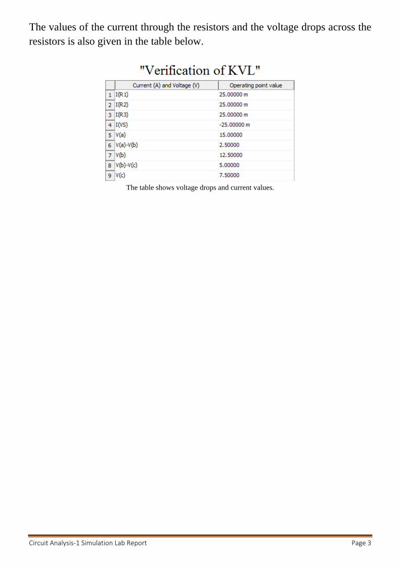
The values of the current through the resistors and the voltage drops across the resistors is also given in the table below.
The table shows voltage drops and current values.
Circuit Analysis-1 Simulation Lab Report Page 3

Circuit Analysis-1 Simulation Lab Report Page 2